an autonomous unmanned aerial vehicle …...1.1.2 remote sensing and agriculture for agriculture...
TRANSCRIPT

AN AUTONOMOUS UNMANNED AERIAL VEHICLE-BASED IMAGERY
SYSTEM DEVELOPMENT AND REMOTE SENSING IMAGES
CLASSIFICATION FOR AGRICULTURAL APPLICATIONS
by
Yiding Han
A thesis submitted in partial fulfillmentof the requirements for the degree
of
MASTER OF SCIENCE
in
Electrical Engineering
Approved:
Dr. HuiFang Dou Dr. YangQuan ChenMajor Professor Committee Member
Dr. Donald Cripps Dr. Byron R. BurnhamCommittee Member Dean of Graduate Studies
UTAH STATE UNIVERSITYLogan, Utah
2009

ii
Copyright c© Yiding Han 2009
All Rights Reserved

iii
Abstract
An Autonomous Unmanned Aerial Vehicle-Based Imagery System Development and
Remote Sensing Images Classification for Agricultural Applications
by
Yiding Han, Master of Science
Utah State University, 2009
Major Professor: Dr. HuiFang DouDepartment: Electrical and Computer Engineering
This work concentrates on the topic of remote sensing using a multispectral imag-
ing system for water management and agriculture applications. The platform, which is a
light-weight inexpensive runway-free unmanned aerial vehicle (UAV), namely, AggieAir, is
presented initially. A major portion of this work focuses on the development of a light-
weight multispectral imager payload for the AggieAir platform, called GhostFoto. The
imager is band-reconfigurable, covering both visual red, green, and blue (RGB) and near
infrared (NIR) spectrum, and interfaced with UAV on-board computer. The development
of the image processing techniques, which are based on the collected multispectral aerial
images, is also presented in this work. One application is to perform fully autonomous river
tracking for applications such as river water management. Simulation based on aerial mul-
tispectral images is done to demonstrate the feasibility of the developed algorithm. Other
effort is made to create a systematic method to generate normalized difference vegetation
index (NDVI) using the airborne imagery. The GhostFoto multispectral imaging system
based on AggieAir architecture is proven to be an innovative and useful tool.
(72 pages)

iv
To my family and friends.
v
Acknowledgments
I would like to thank my advisor, Dr. Dou, for her generous guidance, advice, financial
support, and tremendous help when I am stuck with problems. Without her motivation and
insights this work would have never been complete. Also, I would like to thank Dr. Chen
for giving me this opportunity to join CSOIS and the UAV team, constantly motivating
me, generously supporting me financially in the beginning of my master’s program, and the
extraordinary insights that he has brought to my work. Also, I would like to thank my
committee member, Dr. Cripps, for his comments on my work.
I would like to thank all the CSOIS UAV members, without whom my work would
have been impossible. I would like to thank Haiyang Chao for being a great role model
for me, guiding and helping me in my work, bringing me up to speed initially in the UAV
team, and all the late-night pre-flight tests he participated in. I would like to thank Calvin
Coopmans for helping me to understand Linux and programming Gumstix, creating those
brilliant ideas about AggieAir architecture with me, and all the late-night work he did with
me on different projects. I would like to thank Austin Jensen for inviting me into the UAV
team in the first place, and all the great work he did for us in managing the team, and the
countless flight tests in which he participated. I would like to thank Di Long for building
the airframes and hundreds of backup parts for us, and for participating in the flight tests
for UAV competition. I would like to thank Hu Sheng for building and donating his Tiger
plane for us to participate in the UAV competition. I would also like to thank Chris Hall
and Daniel Morgan for their support and advice. Also, for the other members of the CSOIS,
the help that they gave me on other projects is truly appreciated. I would like to thank
Shayok Mukhopadhyay for the countless late-night work he did with me for the Smartwheel
projects and Sumo robots. He has been such a great friend and helped me enormously with
my English. I would also like to thank Shelley Rounds for helping me in the Mechatronics
lab projects and teaching me the American culture, Varsha Bhambhani for helping me on
the Smartwheel project, and Dr. Yan Li for helping me to understand Fractional Order

vi
Calculus. I would like to thank all the Chinese scholars that visited CSOIS during my
master’s program, for supporting me the whole time and sharing the great Chinese meals
with me. I would also like to thank my friends and roommates who supported me and made
my time at Utah State University enjoyable.
Above all, I would like to thank my family in China, especially my mother, for their
constant selfless support and unwavering belief in me.
Last, but not least, I would like to thank the Utah Water Research Lab for providing
funding for this project.
Yiding Han
vii
Contents
Page
Abstract . . . . . . . . . . . . . . . . . . . . . . . . . . . . . . . . . . . . . . . . . . . . . . . . . . . . . . . iii
Acknowledgments . . . . . . . . . . . . . . . . . . . . . . . . . . . . . . . . . . . . . . . . . . . . . . . v
List of Tables . . . . . . . . . . . . . . . . . . . . . . . . . . . . . . . . . . . . . . . . . . . . . . . . . . . ix
List of Figures . . . . . . . . . . . . . . . . . . . . . . . . . . . . . . . . . . . . . . . . . . . . . . . . . . x
Acronyms . . . . . . . . . . . . . . . . . . . . . . . . . . . . . . . . . . . . . . . . . . . . . . . . . . . . . . xii
1 Introduction . . . . . . . . . . . . . . . . . . . . . . . . . . . . . . . . . . . . . . . . . . . . . . . . . 11.1 Overview . . . . . . . . . . . . . . . . . . . . . . . . . . . . . . . . . . . . . 1
1.1.1 Unmanned Aerial Vehicle . . . . . . . . . . . . . . . . . . . . . . . . 11.1.2 Remote Sensing and Agriculture . . . . . . . . . . . . . . . . . . . . 2
1.2 Motivation . . . . . . . . . . . . . . . . . . . . . . . . . . . . . . . . . . . . 21.3 GhostFoto Multispectral Remote Sensing Platform . . . . . . . . . . . . . . 3
1.3.1 Development Background . . . . . . . . . . . . . . . . . . . . . . . . 31.3.2 Hardware Development for GhostFoto . . . . . . . . . . . . . . . . . 31.3.3 Software Development for GhostFoto . . . . . . . . . . . . . . . . . . 41.3.4 Image Processing . . . . . . . . . . . . . . . . . . . . . . . . . . . . . 5
1.4 Contribution and Organization . . . . . . . . . . . . . . . . . . . . . . . . . 5
2 AggieAir Miniature UAV Architecture . . . . . . . . . . . . . . . . . . . . . . . . . . . 72.1 AggieAir System Overview . . . . . . . . . . . . . . . . . . . . . . . . . . . 9
2.1.1 Airframe . . . . . . . . . . . . . . . . . . . . . . . . . . . . . . . . . 92.1.2 On-Board Electronics . . . . . . . . . . . . . . . . . . . . . . . . . . 102.1.3 Ground Controls . . . . . . . . . . . . . . . . . . . . . . . . . . . . . 12
2.2 Paparazzi . . . . . . . . . . . . . . . . . . . . . . . . . . . . . . . . . . . . . 142.2.1 Paparazzi TWOG Board . . . . . . . . . . . . . . . . . . . . . . . . . 142.2.2 Ground Station . . . . . . . . . . . . . . . . . . . . . . . . . . . . . . 14
2.3 Gumstix On-Board Computer . . . . . . . . . . . . . . . . . . . . . . . . . . 162.3.1 Functionality . . . . . . . . . . . . . . . . . . . . . . . . . . . . . . . 162.3.2 Data Flow . . . . . . . . . . . . . . . . . . . . . . . . . . . . . . . . . 17
2.4 gRAID Image Processing . . . . . . . . . . . . . . . . . . . . . . . . . . . . 19
3 GhostFoto: A Multispectral Remote Sensing Platform . . . . . . . . . . . . . . 213.1 Background and Expectations . . . . . . . . . . . . . . . . . . . . . . . . . . 213.2 GhostFoto Hardware . . . . . . . . . . . . . . . . . . . . . . . . . . . . . . . 22
3.2.1 Cameras . . . . . . . . . . . . . . . . . . . . . . . . . . . . . . . . . . 223.2.2 Near Infrared Camera . . . . . . . . . . . . . . . . . . . . . . . . . . 25
3.3 GhostEye . . . . . . . . . . . . . . . . . . . . . . . . . . . . . . . . . . . . . 26

viii
3.3.1 gPhoto . . . . . . . . . . . . . . . . . . . . . . . . . . . . . . . . . . 273.3.2 Periodic Image Capturing . . . . . . . . . . . . . . . . . . . . . . . . 273.3.3 Calculation of Capture Interval . . . . . . . . . . . . . . . . . . . . . 303.3.4 State Machine . . . . . . . . . . . . . . . . . . . . . . . . . . . . . . 323.3.5 Multithreading Architecture . . . . . . . . . . . . . . . . . . . . . . . 333.3.6 Image Geo-Referencing . . . . . . . . . . . . . . . . . . . . . . . . . 363.3.7 Logging and Debugging . . . . . . . . . . . . . . . . . . . . . . . . . 373.3.8 Implementation in Gumstix . . . . . . . . . . . . . . . . . . . . . . . 373.3.9 Configure GhostEye . . . . . . . . . . . . . . . . . . . . . . . . . . . 37
4 Image Processing . . . . . . . . . . . . . . . . . . . . . . . . . . . . . . . . . . . . . . . . . . . . . 394.1 River Tracking . . . . . . . . . . . . . . . . . . . . . . . . . . . . . . . . . . 39
4.1.1 Motivation . . . . . . . . . . . . . . . . . . . . . . . . . . . . . . . . 394.1.2 Water Area Recognition . . . . . . . . . . . . . . . . . . . . . . . . . 404.1.3 River Tracking Mission . . . . . . . . . . . . . . . . . . . . . . . . . 404.1.4 River Identification . . . . . . . . . . . . . . . . . . . . . . . . . . . . 424.1.5 Way Points Generation . . . . . . . . . . . . . . . . . . . . . . . . . 454.1.6 Results . . . . . . . . . . . . . . . . . . . . . . . . . . . . . . . . . . 47
4.2 Vegetation Recognition . . . . . . . . . . . . . . . . . . . . . . . . . . . . . . 484.2.1 Normalized Difference Vegetation Index . . . . . . . . . . . . . . . . 484.2.2 White Panel Calibration . . . . . . . . . . . . . . . . . . . . . . . . . 50
5 Conclusion . . . . . . . . . . . . . . . . . . . . . . . . . . . . . . . . . . . . . . . . . . . . . . . . . . . 535.1 Contribution . . . . . . . . . . . . . . . . . . . . . . . . . . . . . . . . . . . 535.2 Future Work . . . . . . . . . . . . . . . . . . . . . . . . . . . . . . . . . . . 54
5.2.1 Thermal Infrared Camera . . . . . . . . . . . . . . . . . . . . . . . . 545.2.2 Collaborative Remote Sensing . . . . . . . . . . . . . . . . . . . . . . 555.2.3 Implementation of OpenJAUS . . . . . . . . . . . . . . . . . . . . . 565.2.4 General-Purpose GPU-Based Image Processing . . . . . . . . . . . . 56
References . . . . . . . . . . . . . . . . . . . . . . . . . . . . . . . . . . . . . . . . . . . . . . . . . . . . . . 58

ix
List of Tables
Table Page
3.1 Specifications of PowerShot SX100 IS and SX110 IS. . . . . . . . . . . . . . 24
3.2 Starting transmission wavelength of different NIR filters. . . . . . . . . . . . 26
4.1 Multispectral imager settings for river tracking mission. . . . . . . . . . . . 42
x
List of Figures
Figure Page
2.1 AggieAir system level overview. . . . . . . . . . . . . . . . . . . . . . . . . . 8
2.2 Unicorn airframe. . . . . . . . . . . . . . . . . . . . . . . . . . . . . . . . . . 9
2.3 AggieAir 72 inches UAV layout. . . . . . . . . . . . . . . . . . . . . . . . . . 10
2.4 Electronic devices inside the main bay. . . . . . . . . . . . . . . . . . . . . . 11
2.5 Underneath the aircraft. . . . . . . . . . . . . . . . . . . . . . . . . . . . . . 12
2.6 Paparazzi TWOG board. . . . . . . . . . . . . . . . . . . . . . . . . . . . . 15
2.7 Paparazzi Center. . . . . . . . . . . . . . . . . . . . . . . . . . . . . . . . . . 15
2.8 Paparazzi Ground Control Station (GCS). . . . . . . . . . . . . . . . . . . . 16
2.9 Gumstix Verdex computer-on-module with expansion board. . . . . . . . . 17
2.10 Data flow of AggieAir airborne system. . . . . . . . . . . . . . . . . . . . . . 18
2.11 Aerial imagery mosaic created by gRAID under WorldWind. . . . . . . . . 20
3.1 GhostFinger-DC imager using Pentax Optio E10 camera. . . . . . . . . . . 22
3.2 Canon PowerShot SX100 IS with and without the cover. . . . . . . . . . . . 24
3.3 Canon PowerShot SX100 IS and Canon PowerShot SX110 IS. . . . . . . . . 25
3.4 CCD sensor inside Canon PowerShot SX100 IS, covered by visible light filter. 26
3.5 Software architecture on which GhostEye is based. . . . . . . . . . . . . . . 28
3.6 Imager footprint. . . . . . . . . . . . . . . . . . . . . . . . . . . . . . . . . . 31
3.7 Flowchart of GhostEye control structure. . . . . . . . . . . . . . . . . . . . 32
3.8 Statuses defined in GhostEye state machine. . . . . . . . . . . . . . . . . . . 34
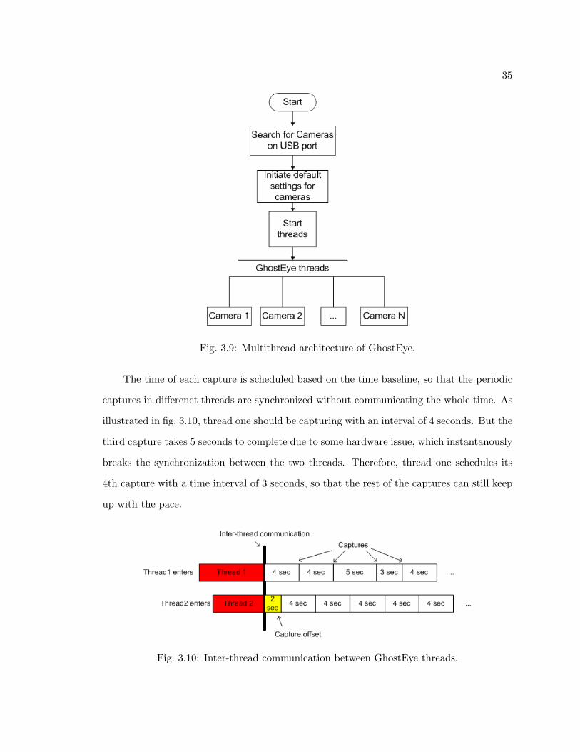
3.9 Multithread architecture of GhostEye. . . . . . . . . . . . . . . . . . . . . . 35
3.10 Inter-thread communication between GhostEye threads. . . . . . . . . . . . 35

xi
3.11 Inter-thread communication to store geo-referencing data. . . . . . . . . . . 36
4.1 NIR and RGB images of a reservoir . . . . . . . . . . . . . . . . . . . . . . 41
4.2 Flight plan of river tracking mission. . . . . . . . . . . . . . . . . . . . . . . 42
4.3 NIR and RGB images of river segment. . . . . . . . . . . . . . . . . . . . . 44
4.4 Histogram of the NIR image. . . . . . . . . . . . . . . . . . . . . . . . . . . 45
4.5 Binary images of the river. . . . . . . . . . . . . . . . . . . . . . . . . . . . . 46
4.6 Dynamic way points generated from the aerial NIR images. . . . . . . . . . 47
4.7 Top view of the dynamic way points. . . . . . . . . . . . . . . . . . . . . . . 48
4.8 NDVI calculation. . . . . . . . . . . . . . . . . . . . . . . . . . . . . . . . . 49
4.9 White panel calibration. . . . . . . . . . . . . . . . . . . . . . . . . . . . . . 50
4.10 NDVI image results. . . . . . . . . . . . . . . . . . . . . . . . . . . . . . . . 52
5.1 Photon 320 uncool TIR camera. . . . . . . . . . . . . . . . . . . . . . . . . . 55
xii
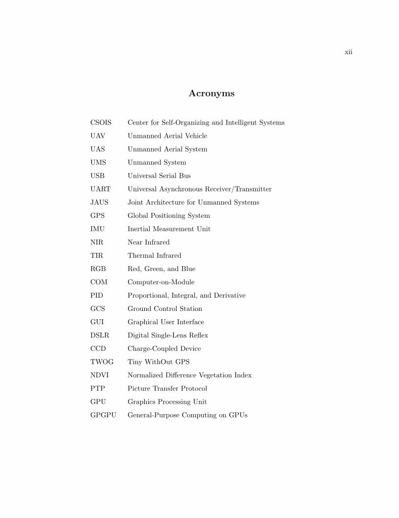
Acronyms
CSOIS Center for Self-Organizing and Intelligent Systems
UAV Unmanned Aerial Vehicle
UAS Unmanned Aerial System
UMS Unmanned System
USB Universal Serial Bus
UART Universal Asynchronous Receiver/Transmitter
JAUS Joint Architecture for Unmanned Systems
GPS Global Positioning System
IMU Inertial Measurement Unit
NIR Near Infrared
TIR Thermal Infrared
RGB Red, Green, and Blue
COM Computer-on-Module
PID Proportional, Integral, and Derivative
GCS Ground Control Station
GUI Graphical User Interface
DSLR Digital Single-Lens Reflex
CCD Charge-Coupled Device
TWOG Tiny WithOut GPS
NDVI Normalized Difference Vegetation Index
PTP Picture Transfer Protocol
GPU Graphics Processing Unit
GPGPU General-Purpose Computing on GPUs

1
Chapter 1
Introduction
1.1 Overview
1.1.1 Unmanned Aerial Vehicle
An unmanned aerial vehicle (UAV) is commonly referred to as a remotely piloted air-
craft, which can either be controlled from a remote location, or fly completely autonomously
according to a pre-planned flight path or real-time navigation system. Ever since its in-
vention, the UAV is mainly used for military purposes [1]. Until recently, a wide vari-
ety of civilian applications have emerged [2], indicating bright market prospects for the
civil/commercial UAVs in the near future.
The UAVs are commonly preferred for missions which are too “dull, dirty, or danger-
ous” [3] for manned aircraft, such as in modern warfare and forest fire fighting [4]. However,
apart from its obvious advantages in risky and hazardous missions, the UAVs also have
many other advantages over manned aircraft, such as higher reliability, lower cost, smaller
dimensions, and better flexibility. With different payloads, UAVs can be tasked for various
applications. Multispectral imagery over a coffee plantation collected by NASA Pathfinder
Plus UAV is used to estimate ripeness status and evaluate harvest readiness [5, 6]. A UAV
from IntelliTech Microsystems, Inc., fitted with five down-looking digital cameras, an up-
looking quantum sensor, is utilized for precision agriculture [7]. Kaaniche et al. [8] presented
a vision algorithm based on a video camera on UAV. The video stream is transmitted to the
ground station for real-time vehicle detection. Also a vision-based road following navigation
system for a UAV is presented [9].

2
1.1.2 Remote Sensing and Agriculture
For agriculture applications, the use of multispectral remote sensing data has gained
increasing interest from researchers all over the world. Pinter et al. [10] has examined the
remote sensing approaches that have been developed for management of water, nutrients,
and pests in agricultural crop. Pinter et al. [10] also addressed the use of thermal infrared
camera which can measure plant temperatures. The thermal infrared camera is able to
remotely assess the water status and predict crop yields. To implement this technology on
UAV platforms, efforts were made by Berni et al. [11] to investigate the use of a thermal
camera and a 6-band multispectral visual camera which is mounted on a helicopter. The
implementation is used to detect water stress and measure the biophysical parameters of
the crops. However, due to the size and weight restraint of small UAVs, usually the smaller
uncooled thermal systems are carried. The issue with the uncooled thermal infrared (TIR)
system is the nonconformity of the images due to temperature change inside the TIR camera.
Wang et al. [12] developed an algorithm called random M-least square to find the optimized
projective transformation parameters between TIR frame. Their results show that the
registered TIR frames are able to create a mosaic and a real-time implementation is possible
in the future.
1.2 Motivation
In the Center of Self-Organizing and Intelligent System (CSOIS) at Utah State Uni-
versity, miniature fixed-wing autonomous UAVs are developed for civil applications such
as water management, irrigation control, vegetation recognition and highway mapping, etc.
The UAV system is named AggieAir. In our previous AggieAir system, the UAVs are
equipped with light-weighted multispectral high-resolution optical imager for aerial images
within reconfigurable bands [13]. Geo-referenced aerial imagery is retrieved with a system
called gRAID [14]. An inexpensive compact inertial measurement unit (IMU) and global
positioning system (GPS) module is integrated in the system to provide geo-referencing
data for the imagery. A man-in-the-loop approach is used to minimized the error from the
IMU and GPS.

3
1.3 GhostFoto Multispectral Remote Sensing Platform
1.3.1 Development Background
A multispectral imager, called the GhostFinger, was developed for our previous UAV
system [15]. The imager system consists of a digital camera and a circuit board which auto-
matically triggers the camera. This system works reliably and captures high quality images,
but it is impossible to communicate with the payload from the ground station. Therefore,
monitoring or controlling the payload during flights was difficult to realize. In addition,
only poor accuracy can be achieved in geo-referencing the airborne imagery. As a result, we
wanted to develop a multispectral imager payload that is able to interface with the on-board
flight microcomputer and the ground control station in order to automatically record the
geo-referencing information for the airborne imagery, as well as providing improved image
quality. In addition, it is designed for multi-purposes and will allow scalable number of
the on-board imagers for both remote sensing and machine vision applications. The novel
imager system is called GhostFoto.
1.3.2 Hardware Development for GhostFoto
GhostFoto multispectral remote sensing platform consists of both hardware and soft-
ware components. The hardware includes a high resolution CCD camera and an on-board
micro computer which controls the cameras through Universal Serial Bus (USB). The cam-
eras can be modified to operate under both visible red, green, and blue (RGB) and near
infrared (NIR) spectrum. A software program, which runs on the on-board micro computer,
is designed to control and configure the cameras in order to capture images autonomously.
The software also records the geo-referencing data with respect to each aerial image.
Canon PowerShot SX100 IS / SX110 IS are the two camera models used in GhostFoto
system. SX110 IS model is the successor of SX100 IS. It is smaller, slightly lighter and able
to capture images with higher resolution. Underneath the cover, the two models feature
the same lens system and fundamentally the same control circuit. Therefore, the effort of
designing software to control the cameras is reusable between these two models.

4
To let the cameras operate under both visible and NIR spectrum, some modification in
the camera’s CCD filter is required. In a normal RGB camera, usually a visible light filter
is placed in front of the CCD array to block NIR spectrum, and only allow visible light to
pass. By replacing this visible light filter with a NIR filter, we can allow only NIR spectrum
to pass and block all the visible spectrum.
A Gumstix Verdex computer-on-module is used as the on-board computer. Verdex
series is based on the Marvell XScale processor, and provided with a Linux operating system
for an OpenEmbedded build environment. The Verdex computer serves as the information
backbone of the UAV on-board system, establishing the data link between sensors and the
auto-piloting system. The sensors include an IMU and a GPS module. IMU is a sensor
which detects the position of an aircraft including pitch, roll, and yaw angles. These sensors
provide not only data which is used to auto-pilot the aircraft, but also critical information
for the orthorectification of aerial images. Therefore, the sensor data is recorded by the
Gumstix computer onto a micro SD card. In addition, the Gumstix computer is also in
charge of controlling and configuring the cameras.
1.3.3 Software Development for GhostFoto
In order to communicate with the cameras from Verdex computer, a Linux-based pro-
gram called the GhostEye was designed. GhostEye is based on libgphoto2, which is an
open source portable digital camera library of C functions for UNIX-like operating sys-
tems, providing supports of various types of digital cameras. With libgphoto2 library func-
tions, GhostEye is able to remotely control and configure multiple Canon PowerShot SX100
IS/SX110 IS cameras simultaneously.
In addition, GhostEye also provides the communication link between the imager pay-
load and the UAV system. Messages can be reported from GhostEye to the ground station
for observation purposes. Meanwhile, messages from the UAV system can trigger the im-
agers. When the UAV climbs up or drops down to a designated altitude, the imagers are
able to be activated or deactivated automatically. Moreover, GhostEye synchronizes image
capturing with the corresponding geo-referencing data. This information is saved in xml

5
format which can be directly imported to gRAID software [16] to orthorectify the image
and map it onto global coordinates.
1.3.4 Image Processing
The different post-processes of the airborne images have been developed aiming for
various application. In the river mapping mission, the imager is used not only to map the
river flow, but can also be used to detect the flow line in real-time and guide the direction of
the UAV. Algorithms are developed based on NIR imagery to detect the river and predict
the river flow, so that dynamic 3D way points are generated. Complete autonomous river
tracking can be realized by implementing the algorithm to generate dynamic way points
which are used by the autopilot system in real-time.
For agricultural applications such as vegetation detection, the Normalized Difference
Vegetation Index (NDVI) is used to detect live green vegetation. The NDVI is widely used
in many applications related to remote sensing, mostly in the agricultural purpose such
as crops ripeness estimation [10, 17], soil moisture estimation [18], and ecological system
study [19], etc. A systematic way of generating high resolution NDVI images is developed
based on GhostFoto multispectral imager and AggieAir UAV system.
1.4 Contribution and Organization
This work concentrates on building the AggieAir architecture and develop the Ghost-
Foto multispectral imager based on the platform. Moreover, the image processing technolo-
gies, which aim at water management and agricultural applications, are developed.
Chapter 2 provides an overview of the AggieAir architecture and a detailed introduction
of every aspects within the architecture, including the airborne system and ground control
system. Chapter 3 deals with the development of GhostFoto multispectral imager system,
providing a detailed explanation of all the functionalities of GhostFoto imager, as well
as the methodology employed to develop such technologies. Chapter 4 focuses on the
image processing technologies develop for different applications based on the AggieAir UAV
platform. The first part of Chapter 4 deals with the river tracking mission developed

6
based on the GhostFoto imagers. The proposed algorithms which are able to identify
the river path and calculate the GPS coordinates of dynamic way points which the UAV
should follow. Simulation results based on multispectral imagery taken from actual flight
test is compared to the real flight trajectory. The second part of Chapter 4 proposes a
systematic way of generating NDVI images based on the multispectral imagery captured by
the GhostFoto imaging system. Chapter 5 gives a conclusion of the contribution presented
in this thesis, and suggests several future works which will lead direction of the AggieAir
UAV development.

7
Chapter 2
AggieAir Miniature UAV Architecture
AggieAir is fundementally an autonoumous aerial vehicle-based remote sensing plat-
form. The system only requires a minimun of two operators to complete the autonomous
flight missions based on pre-planned way points. The plane is launched with a bungee sys-
tem which provides the plane with the initial airspeed enough to takeoff. Then it begins
fully autonomous flight seamlessly after the launching and enters its pre-planned missions.
When the missions are complete, the aircraft is able to autonomously glide to the ground
until it completes the skid landing.
The autopilot unit is called Paparazzi, which is an open source UAV autopilot project.
The flight data required by the autopilot comes from on-board sensors, including a Global
Positioning System (GPS) module and an inertial measurement unit (IMU). The datalink
between the sensors and the autopilot is established by the on-board computer, called
Gumstix, which acts as the information backbone of the airborne system. As a remote
sensing platform, AggieAir features imager payload within reconfigurable bands, including
red, green, and blue (RGB) bands and near infrared (NIR) band. The high resolution
imagers are controlled by Gumstix on-board computer, which both configures the camera’s
settings and controls the shutter to capture images. Airborne imagery is stored either on
the Secure Digital (SD) Card inside the cameras, or in the storage space inside the Gumstix
computer and transmitted down to the ground stations via Wi-Fi communication in real-
time. Other than the autonomous flight capability, AggieAir UAV also has a fail-safe loop
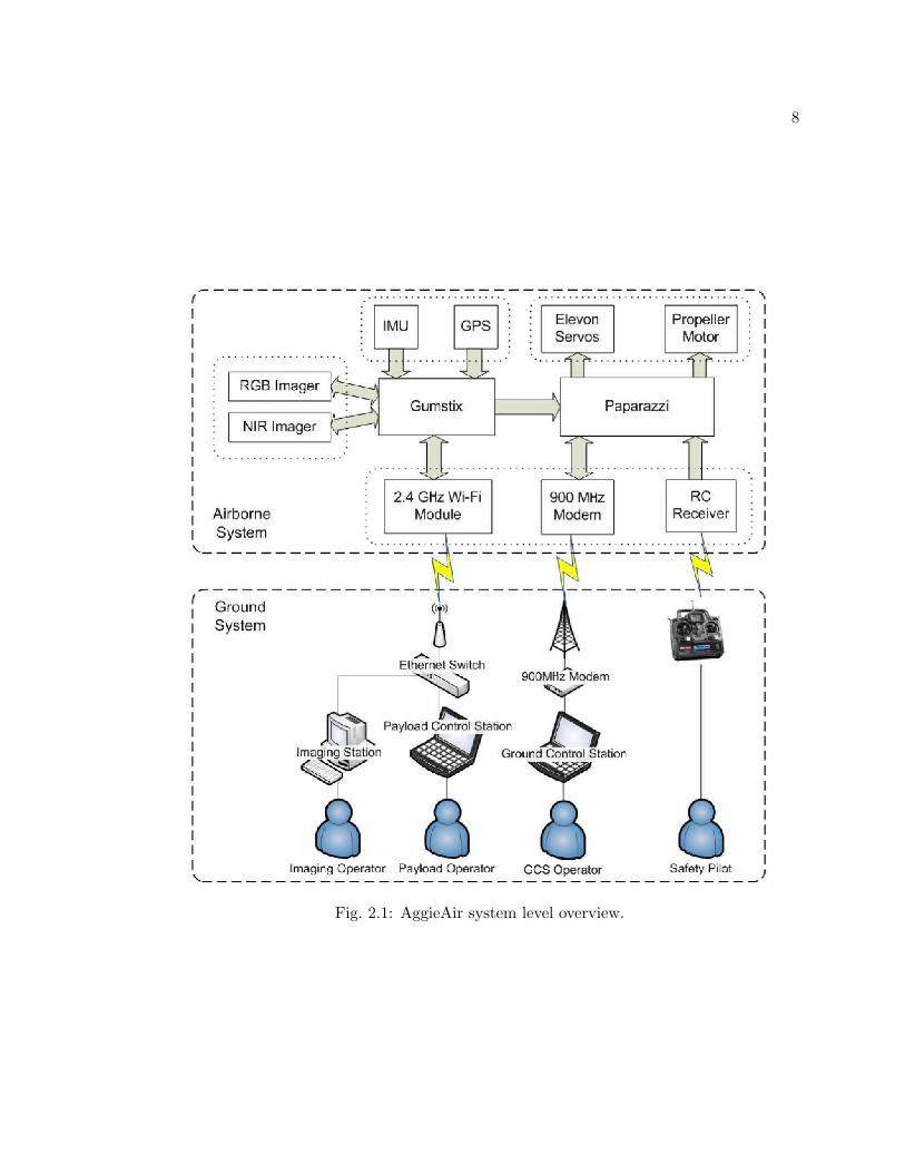
to allow the safety pilot on the ground to take complete control of the aircraft. Figure 2.1
shows a block diagram which helps illustrate the system level overview of the AggieAir
miniature UAV architecture.
8
Fig. 2.1: AggieAir system level overview.

9
2.1 AggieAir System Overview
2.1.1 Airframe
The current AggieAir UAVs are based on Unicorn airframes. This airframe is designed
to have low-speed gliding characteristics, which means it does not tip stall easily even when
it is cruising at low airspeed (< 10m/s). Since the wings are made of resilient foam (EPP),
the body of the aircraft is extremely light. Moreover, upon impact, the foam body is able
to bounce off and absorb the force. Therefore, it is remarkably sturdy and difficult to
break. Apart from the EPP foam body, the airframe is reinforced with embedded carbon
fiber skeleton and thick striping tape skin. Figure 2.2 shows a completed empty Unicorn
airframe.
Modifying or fixing the foam body is easy and low-cost. Most of the body modification
can be done with hot wire foam cutter and utility knives. In serious crash accidents, small
part of the airframe body might be damaged, deformed, or peeled off. These damages can
be easily fixed by gluing new foam pieces and wrapping striping tapes around the injured
spot. However, the Unicorn can be crashed many times without sustaining any noticeable
Fig. 2.2: Unicorn airframe.
10
damage.
2.1.2 On-Board Electronics
The airframe offers different dimensions. Developer can choose among three wingspan
sizes: 48, 60, and 72 inches. The selection of distinct airframes provides flexibility in
building UAVs for specific purposes. The 48-inch for example, has the least weight-bearing
capacity, but the most agile manoeuvrability and the best controllability among the three.
Therefore, it is often utilized in multi-UAV formation flight tests, prototype development,
or crew training. In contrast, the 72-inch airframe carries payload with the most weight,
and is able to cruise with a much more stable posture. The 72-inch is currently the mostly
used airframe in the AggieAir UAV family. It is also the airframe on which the presented
AggieAir architecture is based.
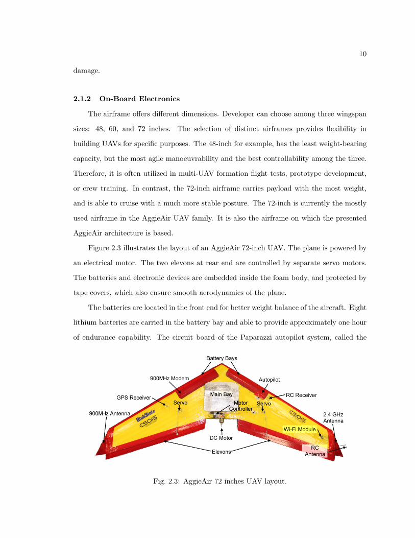
Figure 2.3 illustrates the layout of an AggieAir 72-inch UAV. The plane is powered by
an electrical motor. The two elevons at rear end are controlled by separate servo motors.
The batteries and electronic devices are embedded inside the foam body, and protected by
tape covers, which also ensure smooth aerodynamics of the plane.
The batteries are located in the front end for better weight balance of the aircraft. Eight
lithium batteries are carried in the battery bay and able to provide approximately one hour
of endurance capability. The circuit board of the Paparazzi autopilot system, called the
Fig. 2.3: AggieAir 72 inches UAV layout.

11
TINY board without GPS, or TWOG board, is located in the front of the right wing beside
the batteries. A data modem sits on the other side of the plane on the left wing, providing
the 900 MHz narrow band wireless data link between the on-board autopilot system and the
ground station. Its antenna is placed on the left side of the plane, embedded in the winglet
far away from the other electronics devices to minimize the electromagnetic interference.
Also, a GPS receiver is placed on the left wing. On the right wing, a Wi-Fi module is
seated near the right winglet, connected to the on-board computer through ethernet cable.
A Wi-Fi wide band data link is established with a 2.4 GHz antenna embedded in the right
winglet.
Most of the electronic equipment is protected inside the main bay. As illustrated in
fig. 2.4, the on-board computer, called Gumstix, is located on the left side of the main
bay. A groove is cut beside the Gumstix to allow wind blowing inside the main bay for
cooling purpose. As a result, the vent opening is placed above the groove in order to keep
the Gumstix from water and dusts coming from the environment. An inertial measurement
unit (IMU) is mounted in the middle of the main bay, which is also the center of gravity
of the aircraft. Two imagers are located in the front in parallel positions. In the layout
Fig. 2.4: Electronic devices inside the main bay.

12
illustrated in fig. 2.4, two RGB cameras are mounted. They are tilted with about 20
degrees, facing towards left and right respectively to obtain wider field of view. Underneath
the aircraft, as illustrated in fig. 2.5, viewports are designed to protect the lenses, which
need to reach out of the bottom of the plane to initiate image capturing. The tiled angle
of the cameras can be modified by replacing the viewport with a different one, so that the
same airframe can satisfy the requirements of different applications. A bungee hook is also
installed underneath the aircraft and used during bungee takeoff.
2.1.3 Ground Controls
The ground controls are also essential in the architecture of AggieAir. This concept
might differ from the common knowledge that unmanned vehicles are completely controlled
by themselves without human intervention. But in fact, unmanned vehicles are similar to
manned ones in the sense that human operators are also required, they are just not in the
vehicle, but at a remote location, possibly in front of a computer terminal. This concept
suggests that in an UAV system architecture design, the development of the human ground
control interface is just as important as the airborne systems.
According to fig. 2.1, there are three levels of communication between the ground
control and the UAV. First is the RC communication, which is used by the safety pilot
to manually control the UAV. This is the lowest level of communication, considered as a
Fig. 2.5: Underneath the aircraft.

13
fail-safe approach when the plane’s autonomous system cannot pilot the plane safely. It is
also the first communication link established from the plan to ground control, in order to
trim the airframe in an early stage.
The second level of communication is the data link of the autopilot system. The
autopilot system, known as Paparazzi, is able to create a bi-directional data link with the
ground control station. The downlink, meaning from UAV to the ground, is for transmitting
the flight data, including the flight attitude, GPS information, throttle percentage, battery
status, etc. The operator on the ground is able to use a software with graphical user interface
(GUI), called Ground Control Station (GCS), to monitor all the data in real-time. On the
other hand, data uplink is for transmitting flight commands to the UAV. This involves
changing the way points coordinates, or requesting the UAV to enter a different mission,
etc. However, the second level of communication is still a local communication, which is
based on a 900Mhz wireless connection.
The third level of communication is established upon the 2.4 Ghz Wi-Fi link. The Wi-
Fi module that is used to create this communication is able to hide the wireless details from
the user. Using a network switch which sets up a local ethernet network, every computer
on the ground is able to access to the on-board computer on the UAV. Several operators
on the ground can remotely log onto the on-board computer simultaneously, monitor or
control different aspects of the system, for instance, the resource usage on the on-board
computer including processor and memory usage, or detailed payload status including low-
level system I/O and driver communication, etc. Moreover, the bandwidth of the Wi-Fi link
is tremendous compare to the 900Mhz Paparazzi communication. Airborne images are able
to be transmitted to the ground imaging station and processed in real-time. In addition,
because of the local network, the imagery can be distributed among several computers to
perform image processing simultaneously. And if a Internet router is included in the local
network, the real-time shared aerial images can be accessed remotely from anywhere in the
world.

14
2.2 Paparazzi
2.2.1 Paparazzi TWOG Board
Paparazzi [20] is a free, open-source project, consisting of both hardware and software.
Because of the open-source nature of Paparazzi, developers are supported within a pow-
erful community, sharing their contributions, including software source code, circuit board
schematics, etc. Due to the availability of information, Paparazzi developer are able to
adapt the project for specific applications. Therefore, an exceptionally versatile autopilot
system is developed and still growing with remarkable speed. In CSOIS, developers also
have made considerable contribution to the project. By connecting the Paparazzi TWOG
board with an on-board computer, the sensor data from IMU is linked to the Paparazzi au-
topilot system. Enabling this communication can greatly improve the navigation stability
and control accuracy. Moreover, the accuracy in imagery geo-referencing is considerably
improved compared with the old method in which IR sensors were implemented as the
navigation sensors. In addition to this contribution, CSOIS members also developed the
procedure for fully autonomous takeoff using Paparazzi autopilot.
The main control unit of the autopilot is the Paparazzi TWOG board [21]. The name
TWOG is originated from the initial letters in the phrase “Tiny WithOut Gps,” meaning
the Tiny circuit board without a build-in GPS module. The current v1.00 version TWOG
board features a single Philips LPC2148 MCU, which is based on an ARM7 microcontroller
running at 60 MHz with 512KB of zero wait-state on-chip flash and 40KB SRAM.1 The
TWOG board provides I2C, SPI, UART, USB, eight PWM outputs, and eight analog inputs.
Figure 2.6 shows the front and back side of a TWOG board and illustrates how large it is
compared to a coin.
2.2.2 Ground Station
Free software running on the ground station is provided with a friendly graphical user
interface (GUI). Although the number of available software and functionalities increases140KB is divided as 32KB normal memory and 8KB shared memory with the USB DMA.

15
Fig. 2.6: Paparazzi TWOG board.
almost constantly every once in a while, the most basic packages remain to be the Paparazzi
Center and Ground Control Station (GCS). Paparazzi Center, whose GUI is shown in
fig. 2.7, is used to modify the configuration files for each aircraft, including the airframe,
flight plan, settings, radio, and telemetry. The configuration files are compiled in the
Paparazzi Center, and uploaded to the Paparazzi TWOG board through a USB interface,
or for a simulation, which is run by the simulator inside the Paparazzi Center.
The Ground Control Station (GCS) is the most important tool during flights. GCS
monitors the status and controls the flight of every airborne plane. The communication is
based on the telemetry datalink provided by the 900 MHz antenna. As shown in fig. 2.8, a
2D world map is displayed with the way points of the flight plan, the icon of the plane is also
shown on the map indicating its current location. The execution of way points are defined
as blocks, which can be activated manually or automatically according to the flight plan.
Fig. 2.7: Paparazzi Center.

16
The position of the way points, including latitude longitude and altitude, can be modified
in real-time during flights. GCS also provides parameter tuning of the flight control loops,
meaning the gains for the PID flight controllers can be modified on the run.
2.3 Gumstix On-Board Computer
Gumstix on-board computer is a small yet powerful computer-on-module with a wide
selection of expansion boards which provides extra system I/Os and user interfaces. The
computer-on-module is essentially a computer integrated on a circuit board with very small
footprint. The Verdex / Verdex Pro production line used on AggieAir UAVs has the dimen-
sions of 80mm × 20mm × 6.3mm, featuring a Marvell PXA270 Processor with XScaleTM
running at 600 MHz. The system has 128 MB RAM and a 32 MB ROM, plus an on-board
microSD adapter for extra memory. Figure 2.9 shows a Verdex Pro XL6P computer-on-
module installed with an expansion board, which provides an ethernet connection, a full
speed USB 1.1 port, and three RS232 serial ports.
2.3.1 Functionality
The Gumstix is the backbone of the AggieAir airborne system. It establishes the data
link to send the flight sensor data from IMU and GPS to the Paparazzi autopilot. It also
Fig. 2.8: Paparazzi Ground Control Station (GCS).

17
Fig. 2.9: Gumstix Verdex computer-on-module with expansion board.
controls the payloads and records geo-referencing data and flight logs for airborne imagery.
The Gumstix communicates with IMU, GPS, and Paparazzi TWOG board through serial
ports, and controls the imager payload through a full speed 1.1 USB port. IMU data
packages are updated from the Gumstix to the Paparazzi at 50 Hz. GPS data packages are
slower at 4 Hz due to less frequent updating ratio of the GPS receiver.
As a result, the Gumstix computer bridges the flight sensors and the autopilot, which
means it is able to store and monitor the data flowing through itself. This design enables
a wide range of functionalities for AggieAir UAVs. For instance, by storing the raw flight
data, a flight black box is established. The logged raw data can greatly ease the process
of debugging and failure investigation. Moreover, on-board payloads, regardless of their
specific functionalities, are able to have access to the real-time flight data when interfaced
with the Gumstix computer. As an example, the imager system, including the camera
hardware and the software process within Gumstix, is highly autonomous in the sense that
all of its functionalities are automatically triggered by a software program, which also geo-
references the aerial images with the instantaneous flight sensor information.
2.3.2 Data Flow
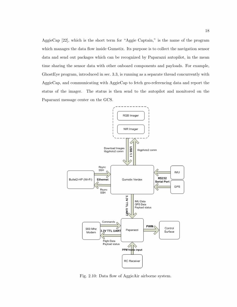
The Gumstix computer runs on an OpenEmbedded Linux operating system. Programs
which runs on the Linux system are designed by CSOIS to enable the data flow within
the Gumstix and hense the entire AggieAir airborne system, as illustrated in fig. 2.10.
18
AggieCap [22], which is the short term for “Aggie Captain,” is the name of the program
which manages the data flow inside Gumstix. Its purpose is to collect the navigation sensor
data and send out packages which can be recognized by Paparazzi autopilot, in the mean
time sharing the sensor data with other onboard components and payloads. For example,
GhostEye program, introduced in sec. 3.3, is running as a separate thread concurrently with
AggieCap, and communicating with AggieCap to fetch geo-referencing data and report the
status of the imager. The status is then send to the autopilot and monitored on the
Paparazzi message center on the GCS.
Fig. 2.10: Data flow of AggieAir airborne system.

19
Another key data flow is also related to the Gumstix computer, and is established
through a broadband 2.4GHz Wi-Fi communication. On the hardware level, the Wi-Fi
communication is based on inexpensive, high-power (800mW), and easily constructed “car-
rier class” Wi-Fi units, manufactured by Ubiquity Wireless [23], known as the Bullet2-HP.
The units are employed on both ends communication link. As a result, on the software level,
the network is similar to an ethernet connection, since Bullet2-HP has hidden the details
of wireless connection from the end user. This Wi-Fi link has a tested effective range of
approximately two miles and is able to achieve up to 1.6 MB/s transfer speeds, depending
on the choice of antennas.
The Wi-Fi link enables a broadband communication compared with the Paparazzi
900MHz datalink. Large amount of data flow is able to be transmitted to, or from, the
ground station directly. For the current system, the Wi-Fi link is used for downloading
real-time airborne imagery and monitoring on-board system status on the ground stations.
2.4 gRAID Image Processing
Once the airborne images are downloaded to the ground stations, a software called
gRAID, which stands for Geospatial Real-time Aerial Image Display, is employed to pro-
cess the imagery by orthorectifying the images with respect to their geo-referencing data
recorded in the UAV on-board system, and overlaying the images onto an actual 3D earth
within NASA’s WorldWind [24] software. Figure 2.11 illustrates the results of the mosaic
of airborne images of a river overlaid on the 3D map in WorldWind.

20
Fig. 2.11: Aerial imagery mosaic created by gRAID under WorldWind.

21
Chapter 3
GhostFoto: A Multispectral Remote Sensing Platform
As a remote sensing platform, it is important to develop a multispectral imager that
is reliable, inexpensive, light-weighted, compatible with the AggieAir architecture, and also
captures images with high resolution. Therefore, GhostFoto multispectral remote sensing
imager is developed for the AggieAir architecture, and is designed to feature the following
functionalities:
• Interfaced with the on-board Gumstix computer,
• Autonomously managed capturing,
• Geo-referencing data logging,
• Monitor-able from ground station,
• Controllable from ground station,
• Support multiple cameras,
• Flexible cameras collocation,
• Full manual control over the cameras.
3.1 Background and Expectations
Prior to the GhostFoto multispectral imager, a GhostFinger-DC system was devel-
oped [15] and used on a Procerus airframe. The old design was based on an additional
hardware interfaced to a Pentax camera to trigger the camera to capture images. The sys-
tem, as illustrated in fig. 3.1, is proved to work reliably for capturing images periodically.
However, geo-referencing of the images appears to be difficult with this system. Since the

22
Fig. 3.1: GhostFinger-DC imager using Pentax Optio E10 camera.
imager is isolated from the flight system, it needs to carry its own GPS module, a pressure
sensor, an SD card, and an inclinometer to record the geo-referencing data for each picture.
Another issue with the camera is that it does not allow users to have fully manual optical
configurations. Although the aperture size and shutter speed can be manually configured,
the white balance setting is still automatically configured by the camera. The different color
behaviors result in a map of nonuniform images.
As a result, a new multispectral imager is required to be developed. It is called Ghost-
Foto. Its most remarkable improvement over the old design is that the GhostFoto imager
is interfaced with the on-board computer, so that it will greatly benefit from the AggieAir
architecture in terms of information sharing. The software which is designed to control the
cameras is based on an open source digital camera library called the libgphoto2, which is
compatible with UNIX-like operating systems. A new type of camera will also be used in
the GhostFoto imaging system, providing complete manual configuration and better optical
lens system.
3.2 GhostFoto Hardware
3.2.1 Cameras
Although a wide variety of commercial off-the-shelf CCD digital cameras exist in today’s

23
market, there are few that satisfy all the requirements offered by the GhostFoto imaging
system. These requirements are listed as following:
• Supported by libgphoto2,
• Enables remote controlled capturing,
• Remote capturing is supported by libgphoto2,
• Allow complete manual control,
• Manual setting configurable by libgphoto2,
• Fast capture rate,
• Preferably zoom-able lens system,
• High resolution CCD array,
• Light-weighted, small dimension, and inexpensive.
PowerShot SX100 IS camera manufactured by Canon falls in one of the best candidates.
Other choices are available, but they are mostly digital single-lens reflex (DSLR) cameras
with outstanding image quality but enormous dimensions. For example, the Nikon D40x
is probably one of the most compact DSLR available in the market, but is still over-sized.
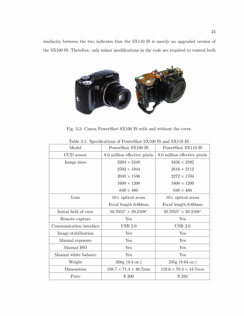
As a result, the PowerShot SX100 IS, shown in fig. 3.2, is chosen1 because of its compact
size and relatively light weight, which is approximately 200 grams after the cover and LCD
panel are disassembled. This weight is light enough for the 48 inches airframe UAV to carry
one imager, and the 72 inches airframe to carry two imagers. Specifications of the camera
are listed in table 3.1 [25].
Canon PowerShot SX110 IS, which is the successor of the SX100 IS, entered market
in the late 2008. The new camera features a nine million effective pixels CCD sensor,
and smaller dimensions. The comparison with its predecessor is demonstrated in fig 3.3.
However, the two models share the same optical lens and a similar electronic system. The1The choice was made in August 2008.
24
similarity between the two indicates that the SX110 IS is merely an upgraded version of
the SX100 IS. Therefore, only minor modifications in the code are required to control both
Fig. 3.2: Canon PowerShot SX100 IS with and without the cover.
Table 3.1: Specifications of PowerShot SX100 IS and SX110 IS.Model PowerShot SX100 IS PowerShot SX110 IS
CCD sensor 8.0 million effective pixels 9.0 million effective pixels
Image sizes 3264× 2448 3456× 2592
2592× 1944 2816× 2112
2048× 1536 2272× 1704
1600× 1200 1600× 1200
640× 480 640× 480
Lens 10× optical zoom 10× optical zoom
Focal length 6-60mm Focal length 6-60mm
Initial field of view 50.7055◦ × 39.2108◦ 50.7055◦ × 39.2108◦
Remote capture Yes Yes
Communication interface USB 2.0 USB 2.0
Image stabilization Yes Yes
Manual exposure Yes Yes
Manual ISO Yes Yes
Manual white balance Yes Yes
Weight 266g (9.4 oz.) 245g (8.64 oz.)
Dimensions 108.7× 71.4× 46.7mm 110.6× 70.4× 44.7mm
Price $ 200 $ 250

25
(a) Front view.
(b) Top view.
Fig. 3.3: Canon PowerShot SX100 IS and Canon PowerShot SX110 IS.
models.
3.2.2 Near Infrared Camera
To meet the needs of multispectral remote sensing, cameras which can detect near in-
frared (NIR) band is required. According to the previous research [15,16], CCD sensors are
sensible to both red green and blue (RGB) bands and NIR band. However, manufactures
usually install a visible light filter in order to prevent the NIR light from causing overex-
posure on the RGB CCD sensors. Hence, by replacing the visible light filter with an NIR
filter, which let pass only NIR band, a normal RGB CCD camera can be modified to an NIR
camera. The CCD sensor and filter in a PowerShot SX100 IS camera is shown in fig. 3.4.
There are several standard filters provided by different manufactures, including Ho-
yaR72 filter (glass), Kodak Wratten 87 filter (Wratten), Lee 87 filter (polyester), and Lee

26
Fig. 3.4: CCD sensor inside Canon PowerShot SX100 IS, covered by visible light filter.
87C filer (polyester). Their starting transmission wavelength are listed in table 3.2. Our
choice is the Lee 87C filter.
3.3 GhostEye
GhostEye is a program designed based on libgphoto2 API to manage the on-board
cameras. It is written for Linux operating system and should be compatible with other
UNIX-like systems. The main functionality of this program is to access one or several cam-
eras, configure their settings, control the periodical capturing, and record geo-referencing
data with respect to every image.
Table 3.2: Starting transmission wavelength of different NIR filters.Filter name Starting transmission wavelength (NM)
Hoyle72 720
Kodak Wratten 87 750
Lee 87 750
Lee 87C 800

27
3.3.1 gPhoto
gPhoto [26] is an open source project to support digital cameras under UNIX-like sys-
tems. As of now more than 1100 cameras [27] are supported by gPhoto. The project consists
of several individual sub-projects, including gphoto2, libgphoto2, and gtkam. libgphoto2,
the core of gPhoto project, is a portable library of APIs that access to the digital cameras.
But for normal users, command lines or graphical front-end interfaces are required to utilize
the libgphoto2 APIs. The command line interface is provided by gphoto2, and the GUI is
provided by gtkam.
In order to manage GhostFoto cameras, a program called GhostEye is designed based
on the libgphoto2 API. When GhostEye project started, the stable version of libgphoto2
was 2.4.2, in which the supports of Canon PowerShot SX100 IS was provided. However,
the support was not 100% complete, so there were a few bugs in the APIs. The solutions
to overcome the issues caused by these bugs will be discussed in sec. 3.3.2.
The later version of libgphoto2 fixed most of the software issues. The 2.4.5 version is
the latest stable version of libgphoto2 that GhostEye is based on. Also the new PowerShot
SX110 IS camera is supported in this version, whereas it was not in the 2.4.2 one.
In fig. 3.5, the architecture of the software is illustrated. GhostEye accesses the
front-end of libgphoto2 API, it also accesses some of the low-level APIs provided by libg-
photo2 port library, which is a subsidiary library under libgphoto2, providing basic operat-
ing system level communication with USB ports, RS232 serial ports, and other ports that
might be used by some digital cameras.
3.3.2 Periodic Image Capturing
In this section, the discussion of the imager system is simplified in the way that only one
camera is connected with a Linux system through the USB port. The system environment
is defined as the following: the 2.4.2 version libgphoto2 is installed on the Linux system;
PowerShot SX100 IS camera is connected and able to be detected by gphoto2; a USB port
number is assigned to this camera by the operating system.

28
Fig. 3.5: Software architecture on which GhostEye is based.
Initially, algorithm 3.1 is used to enable the periodic image capturing. To simplify the
explanation, a pseudo function “ghosteye init camera()” is called to finish the initialization
of the camera, the parameters of the function are omitted here. Similarly, pseudo function
“ghosteye extend lens()” is called afterward to reach out the optical lens in order to enable
capture. A libgphoto2 function which triggers the capture needs to be called inside a loop
for iterative capturing, with certain time interval. The value of the time interval, which is
4 seconds in this case, is set long enough for the camera to finish its operation. The return
value of the libgphoto2 function is checked at every iteration, where the term GP OK, whose
value is defined as 0 in libgphoto2 libraries, indicates no error has occurred.
However, due to the bug issue in the 2.4.2 version libgphoto, algorithm 3.1 does not
work at all. Instead, the function will take two shots, store the first image in the camera
SD card, and return failure for the second shot. As a result, a modified procedure, shown
in algorithm 3.2, is designed to overcome this issue.

29
Algorithm 3.1 Periodic Capture 1ghosteye init camera (...); /* Initialize Canon PowerShot SX100 IS */ghosteye extend lens (...); /* Extend camera lens */...while (retval == GP OK){
retval = gp camera capture (...); /* Calling libgphoto2 function */...sleep (4.0); /* Sleep for 4 seconds */}
Algorithm 3.2 Periodic Capture 2ghosteye init camera (...); /* Initialize Canon PowerShot SX100 IS */ghosteye extend lens (...); /* Extend camera lens */ghosteye retract lens (...); /* Retract camera lens */...ghosteye extend lens (...); /* Extend camera lens again */gp camera capture (...); /* Take a picture, but ignore the false return value */...while (retval == GP OK){
retval = gp camera capture (...); /* Calling libgphoto2 function */...sleep (4.0); /* Sleep for 4 seconds */}

30
The changes made in algorithm 3.2 are mostly in the beginning section before entering
the capturing loop. Although there is hardly any scientific explanation, this method is
proved to work reliably. As shown in the algorithm, the camera lens is being extended two
times after the initialization, and followed by capturing a picture. However, this particular
shot is also counted as an initialization process, for the libgphoto2 function will return
failure with a value of “-10.” Ignoring this error, the following shots by the same libgphoto2
function will work nicely in a periodic way.
A file name issue, however, does exist in algorithm 3.2. The first shot, which appears
to be failure, actually succeeds in taking a picture and storing it in the SD card. A file
name, automatically assigned inside the Canon camera, is given to the first picture, usually
as “IMG0000.JPG.” But due to the false exit of the libgphoto2 function, the counter of
picture number inside libgphoto2 fails to increase. As a result, when the following shots are
taken, the numbers in the correct file names, which are assigned inside the Canon camera,
are always one larger than those in the file names returned by libgphoto2. For example, the
name of the picture taken after the first one should be assigned as “IMG0001.JPG.” But it
is still “IMG0000.JPG” that is reported from libgphoto2. Due to this issue, downloading
the images in real-time is very difficult to be realized with libgphoto2 2.4.2.
This bug is fixed in the releases after libgphoto2 2.4.4 version. Therefore, technically
speaking, algorithm 3.1 can be applied without any issue with libgphoto2 2.4.5. But algo-
rithm 3.2 still gets inherited. The reason is not only for backward compatibility, but also
that this design is quite welcomed by the end-users. Extending and retracting the optical
lens during initialization provides the UAV operators with a visual confirmation, so that
failure of initialization can be identified in an early stage before the UAV is launched.
3.3.3 Calculation of Capture Interval
The time interval between each picture is set accordingly to the demands of certain
flight missions. For example, for a task of ground mapping, aerial images would need to be
stitched together to form a complete ground map. The stitching algorithm requires certain
amount of overlapping between the adjacent images, normally with an area of a minimum

31
of 30% of the whole image. Chao et al. [13] presented eq. (3.1) to calculate the minimum
time interval. Therefore, when the UAV flies at 300 meters above ground with a ground
speed of 15 m/s, the minimum time interval to reach 30% of overlapping is 10.8 seconds.
Equation (3.1) is defined as:
tmin =(1− p%)× Fy
v, (3.1)
where p% is the percentage of overlapping area, Fy is the vertical length of the footprint of
GhostFoto imager, as illustrated in fig. 3.6. v is the speed of the plane. Fy is calculated
from eq. (3.2) defined as:
Fy =h× Py × PN
f, (3.2)
where h is the flight height, Py is the pixel size, and PN is the number of pixels on the
CCD array. f is the focal length of the camera. In case of a PowerShot SX100 IS camera:
Py = 4.31PN
(mm), PN = 2448, f = 6(mm).
The PowerShot SX100 IS RGB cameras can capture image with a maximum speed of 0.4
Fig. 3.6: Imager footprint.

32
picture/second (2.5 seconds capture interval). For NIR cameras a capture interval of three
seconds is achievable due to the less optical flux of the NIR filter. If two RGB cameras are
carried in one flight mission and used to capture images alternately, the maximum capture
speed is then doubled. At this rate, the plane is able to fly as low as 50 meters above the
ground altitude, yet still maintain sufficient overlapping area between the adjacent images.
3.3.4 State Machine
The actual design of GhostEye program is more refined than the algorithms presented
in sec. 3.3.2. A ghosteye object is declared for only one camera during initialization. This
ghosteye object is defined to encapsulate data and structure such as the camera object
defined by libgphoto2, camera settings, and a GhostEye periodic control thread, etc. Instead
of a single while loop, a state machine is designed as the main control architecture. The
flowchart of the architecture is demonstrated in fig. 3.7.
State machine is a device that stores the status of the object and changes its status for a
given input at a given time. A state machine is designed inside the ghosteye object to define
Fig. 3.7: Flowchart of GhostEye control structure.

33
the status of GhostFoto imager. The state machine of GhostEye threads is illustrated in
fig. 3.8. Each state is marked with a different color, correspondingly to the colors in fig. 3.7.
Eight states are defined for the imager, including an “Abnormal” state which is used when
the libgphoto2 function returns with error.
As shown in fig. 3.8, each state can jump to another state only when certain requirments
are met. For example, the initial status of the state machine is “non-initialized.” And then
once the camera is successfully found and set up, the state machine enters “initialized”
status. In this state, GhostFoto imager is in a stand-by status and ready to start capturing
images. Once the start capturing command is committed by the user, the imager will switch
to “enabling capture” status to extend the lens and then enter the periodic capturing loop.
When the camera is in the “ready to capture” status, the state machine is waiting on
a timer for the next scheduled shoot, then it jumps to the “capturing” status to take a
picture and “logging data” status to log the geo-referencing data. During the “ready to
capture” period, the state machine also checks if the user has sent any stop-capture signal.
Once found such signal, the state machine will switch to “disabling capture” status, in
which the camera lens is being retracted, then the “initialized” status to stay in stand-by,
waiting for orders from user to start capturing again. Three of the eight states, “enabling
capture,” “capturing,” and “disabling capture,” involve calling fucntions that interface with
the camera hardware and, therefore, might result in failure. If happens, the state machine
will enter the “abnormal” status, trying to resolve to problem based on the return value of
libgphoto2 functions, or hibernate if the problem is not fixable.
Different values are defined to represent the statuses of the state machine. The envi-
roment is able to read these values in real-time via the APIs provided by GhostEye. Thus
the status of the imager is able to be monitored in the rest of the UAV system.
3.3.5 Multithreading Architecture
Cameras are recognized by GhostEye during program initialization. GhostEye searches
for Canon PowerShot SX100 IS cameras through the USB 1.1 port. Once found, a thread
which controls the camera is created. Therefore, as shown in fig. 3.9, the cameras are

34
Fig. 3.8: Statuses defined in GhostEye state machine.
controlled separately by individual threads under GhostEye.
The multithreading architecture of GhostEye can ensure the flexibility and robustness
of the system. With more than one cameras on board, the multithreading architecture
is able to synchronize the capture very accurately. Also in situations that one camera
malfunctions, the other cameras would not be affected.
Inter-thread communication is established to ensure the accuracy of synchronization
among the GhostEye threads. However, the cost of inter-thread communication is relatively
high, and therefore, not suitable to be called too frequently. Instead, GhostEye only uti-
lizes inter-thread communication in the beginning of all GhostEye threads. As illustrated
in fig. 3.10, two GhostEye threads are synchronized shortly after their entries. The syn-
chronization is time-stamped, and considered as a time baseline (or time 0) to schedule all
the captures.
35
Fig. 3.9: Multithread architecture of GhostEye.
The time of each capture is scheduled based on the time baseline, so that the periodic
captures in differenct threads are synchronized without communicating the whole time. As
illustrated in fig. 3.10, thread one should be capturing with an interval of 4 seconds. But the
third capture takes 5 seconds to complete due to some hardware issue, which instantanously
breaks the synchronization between the two threads. Therefore, thread one schedules its
4th capture with a time interval of 3 seconds, so that the rest of the captures can still keep
up with the pace.
Fig. 3.10: Inter-thread communication between GhostEye threads.

36
Thread two uses a feature called capture offset, which intentionally delays every shot by
two seconds after thread one. As a result, the two cameras are taking pictures alternertively
in a synchoronized pace. The reason of this configuration is due to the bandwidth limit
of the USB 1.1 port on the Gumstix Verdex Pro computer, which greatly constrains the
amount of data transmitted within a short period of time. By spreading the load more
evenly along the temporal space, real-time high resolution images can be downloaded from
the camera to the Gumstix without causing any delay in the image capturing.
3.3.6 Image Geo-Referencing
When images are being captured, geo-referencing data of the images is logged by Ghost-
Eye. The data contains the flight information from the on-board IMU and GPS. The IMU
provides pitch, yaw, and roll angles of the plane, and GPS module offers the geograph-
ical coordinates of the plane such as altitude, longitude, and latitude, etc. The sensor
data is sampled at the time instant when each images is taken, and saved accordingly to
each picture name in an xml file. With this information, every pixel on the image can be
orthorectified and its geographical coordinates can therefore be calculated.
GhostEye provides APIs to fetch the sensor data from the enviorment in real-time. A
data pool which stores the most recently updated sensor data is allocated in GhostEye, for
the control threads to access whenever an image is captured. The structure is illustrated
in fig. 3.11. However, because GhostEye program is running in a separate thread from the
Fig. 3.11: Inter-thread communication to store geo-referencing data.

37
main enviroment thread, inter-thread communication is used to ensure the safety of the
data. But the detail of this operation is completely hidden from the enviroment.
3.3.7 Logging and Debugging
GhostEye is able to log the geo-referencing data in an xml file, which includes the IMU
and GPS sensor data, image file information, camera field of view, etc. gRAID software is
able to read the xml files and import the aerial images accordingly.
Besides the geo-referencing data, GhostEye also has a status log in order to keep the
record of its operations. The log saves the initialization results of cameras, configurations of
the camera, and information about each image capture, including capture time stamp, time
interval between shots, etc. When malfunctioning happens, the log is able to record the
source and type of the error, providing critical information to trace back the cause of the
failure. Moreover, a low level log based on libgphoto2 is established to record the operating
system level USB port communications and camera driver operations.
3.3.8 Implementation in Gumstix
In order that GhostEye software can obtain sensor data and talk with the other parts
of the UAV system, its implementation in Gumstix is based on Gx2 software, which is an
AggieCap program that is designed for MicroStrain Gx2 IMU. The two programs, Gx2 and
GhostEye, are compiled together in one program, namely GhostGx2, which runs under the
OpenEmbedded Linux system on Gumstix. Separate threads are running within GhostGx2,
including the main thread, which is the Gx2 program, and the GhostEye threads. Inter-
process communication is set up between Gx2 and GhostEye to share the flight sensor data
and GhostFoto imagers status. Due to the multithreading structure, GhostGx2 can run
robustly and free of interruption among the threads.
3.3.9 Configure GhostEye
A “GhostEye.ini” file is saved on the Gumstix home folder. It stores the camera
configurations and a few other settings for the GhostFoto imaging system. When the user

38
needs to specify setting for the system, parameters inside this file needs to be changed before
the initialization of the on-board computer system. During initialization process this file is
automatically loaded by the GhostEye and the configurations are set to be constant inside
GhostEye.

39
Chapter 4
Image Processing
4.1 River Tracking
4.1.1 Motivation
This river tracking project is part of a river mapping application, in which AggieAir
UAV is required to capture aerial multispectral images of a river segment.
Due to the high spatial and temporal resolution of the UAV-based imaging system,
current multispectral images of the river segment can be geo-referenced and mapped onto
geographic information systems, then monitored by end users in little time delay. This will
greatly benefit the applications such as river water resource management, river geographical
information collection, and aquatic ecosystem study, etc.
In this section, an approach for autonomously generated real-time dynamic way points
is developed. In most cases, the pre-planned way points that the AggieAir UAVs navigation
system uses are generated from known geographical information, usually satellite images.
However, many rivers alter their flow path seasonally due to drought or flood. But satellite
images of such rivers may not update frequently enough to report this change. This suggests
that if the UAV follows the way points generated from those outdated satellite images, the
UAV airborne images might not completely cover the changed river flow. Therefore, the
navigation system is required to have the ability to follow deviations in the river’s path.
In this case, the UAV’s flight path is controlled based on a real-time close-loop system in
which GhostFoto imaging platform can provide feedback of the river direction, as well as
multispectral imagery of the river.

40
4.1.2 Water Area Recognition
In order to follow the river, an algorithm which can detect the water area is developed.
GhostFoto multispectral imager is able to detect objects within the near infrared (NIR)
spectrum. Due to the absorbtion nature of liquid water to NIR spectrum, the water areas
all appear to be remarkably dark in a NIR image. The multispectral aerial images shown
in fig. 4.1 illustrate this effect.
It is obvious in fig. 4.1(a) that the water area of the image is the darkest part and has
a strong contrast compared to the rest of the picture. Moreover, the shade of cloud has no
effect on the darkness of the water area. Although it darkens the land area, the contrast
against water area is still differentiable. On the other hand, in fig. 4.1(b), the water area
appears greenish, which is very close to the color of vegetation. Moreover, this color may be
different on other water areas, such as deep lake or shallow creek where water can appear
to be darker, bluish or possibly transparent. Furthermore, the cloud shade shown in this
picture illustrates apparent effect on the reservoir’s greenish color. As a conclusion, using
RGB pictures for water area detection is difficult because of its non-unique and inconsistent
appearance. In contrast, NIR images can be considered as a reliable source to distinguish
water areas.
4.1.3 River Tracking Mission
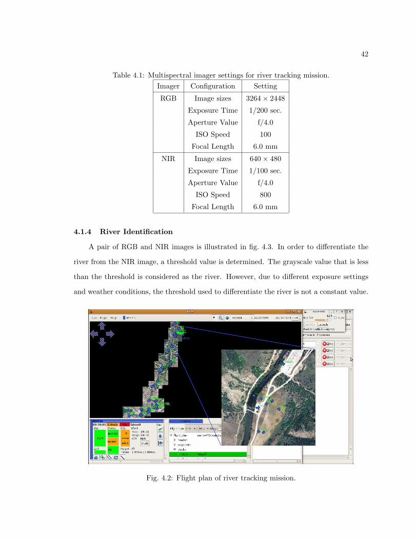
The imagery used in this research was collected during a flight test over Onerda Narrows
in Preston, Idaho. Launch site coordinate was at latitude 42.263800, longitude -111.752220.
The flight went from North to South along the riverflow for 9 miles. Fifty-six pairs of NIR
and RGB images taken in the first 1.2 miles of flight were picked out of the imagery.
In this case, NIR imager is used as the “path finder” due to its ability to highlight the
river area. Meanwhile, the RGB imager captures high resolution pictures of the river, which
is later stitched together in gRAID into a complete map of the river segment. However, it is
not necessary to collect high resolution NIR images, for they need to be processed in order
to detect the riverflow. Therefore, smaller image size, such as 640×480 resolution, actually
speeds up the process but suffers from little accuracy loss. The settings of both cameras

41
(a) NIR
(b) RGB
Fig. 4.1: NIR and RGB images of a reservoir.
are listed in table 4.1. The 9-mile-long flight plan made in Paparazzi GCS is illustrated in
fig. 4.2.
42
Table 4.1: Multispectral imager settings for river tracking mission.Imager Configuration Setting
RGB Image sizes 3264× 2448
Exposure Time 1/200 sec.
Aperture Value f/4.0
ISO Speed 100
Focal Length 6.0 mm
NIR Image sizes 640× 480
Exposure Time 1/100 sec.
Aperture Value f/4.0
ISO Speed 800
Focal Length 6.0 mm
4.1.4 River Identification
A pair of RGB and NIR images is illustrated in fig. 4.3. In order to differentiate the
river from the NIR image, a threshold value is determined. The grayscale value that is less
than the threshold is considered as the river. However, due to different exposure settings
and weather conditions, the threshold used to differentiate the river is not a constant value.
Fig. 4.2: Flight plan of river tracking mission.

43
In order to take account for the variable threshold value in every iamge, a histogram-based
method is used to determine this threshold value. The histogram of an image illustrate the
distribution of colors shown in the image. Usually, objects with uniformed color appear to
be a single crest in the histogram.
As shown in fig. 4.4, the histogram plots the distribution of the grayscale values of
the NIR image illustrated in fig. 4.3(a). It is obvious that the colors are distributed near
two crests, one is near the value of 50, the other is near 140. The crest near 50 is caused
by the river area, where colors are extraordinarily darker than the surroundings. On the
other hand, the 140 crest is caused by the land area, which usually appears to be bright
since the NIR light is not absorbed but mostly reflected by vegetation. Therefore, the
threshold of image is located within the trough between the crests, with a value of about
80. An algorithm is made in Matlab to automatically detect value of the trough between
two crests. Based on this method, a comprehensive way to automatically determine the
threshold value is developed. The algorithm is tested on the 56 sets of NIR images, and
able to achieve 100% successful rate in identifying the water area.
Once the threshold is determined, a binary image can be created from the original
grayscale image, with a simple equation shown as the following:
BW = (N < gt), (4.1)
where BW stands for binary value of 0 or 1. N is the grayscale value of one pixel in the NIR
image. gt stands for the value of the threshold. (.) is defined as the conditional operator,
which equals to 1 if the condition inside it holds true, otherwise it is equal to 0.
Shown in fig. 4.5(a), the binary image of the river is created using eq. (4.1). White
pixels represents water area, and the black ones for undefined object. However, it is obvious
that noise exists in the water area. Also several small objects that are not within the river
path is highlighted to be white. In order to get rid of the noise and obtain a binary image
with only the river path highlighted, some morphological image analysis are needed.
The first step is to fill the holes in the binary image. Holes are defined as a set of

44
(a) NIR
(b) RGB
Fig. 4.3: NIR and RGB images of river segment.
background pixels that cannot be reached by filling in the background from the edge of the
image. In our case, holes are the black pixels which are completely surrounded by white
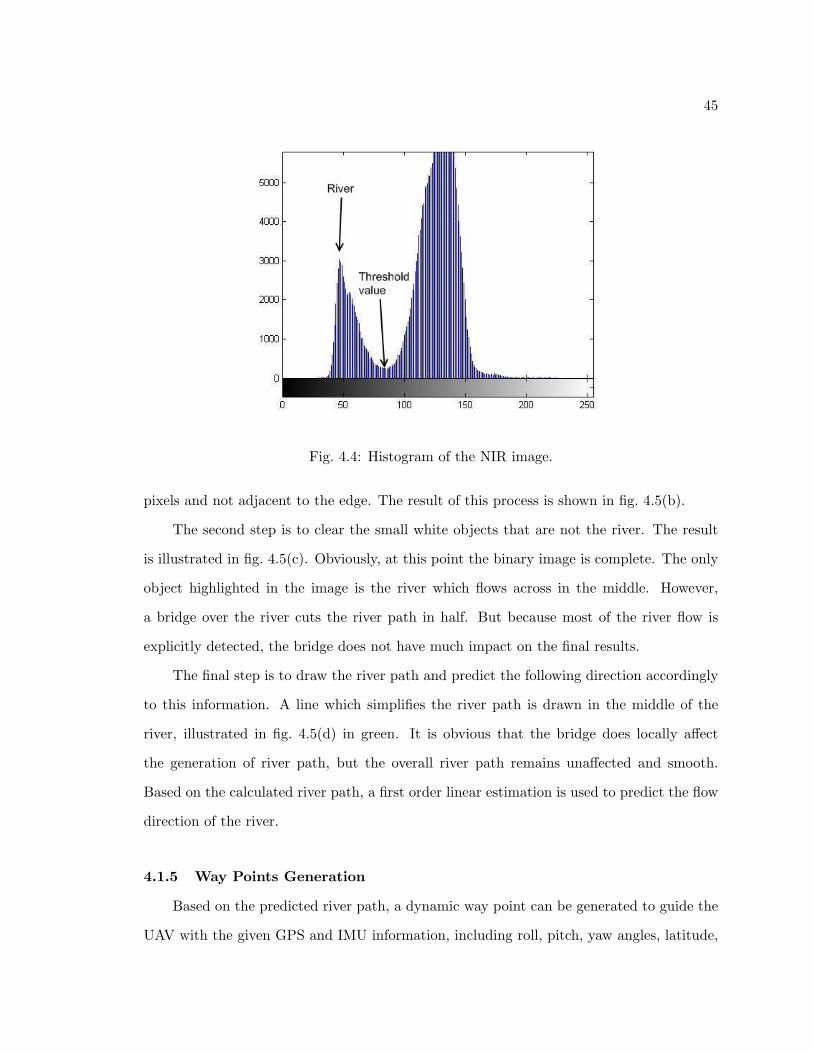
45
Fig. 4.4: Histogram of the NIR image.
pixels and not adjacent to the edge. The result of this process is shown in fig. 4.5(b).
The second step is to clear the small white objects that are not the river. The result
is illustrated in fig. 4.5(c). Obviously, at this point the binary image is complete. The only
object highlighted in the image is the river which flows across in the middle. However,
a bridge over the river cuts the river path in half. But because most of the river flow is
explicitly detected, the bridge does not have much impact on the final results.
The final step is to draw the river path and predict the following direction accordingly
to this information. A line which simplifies the river path is drawn in the middle of the
river, illustrated in fig. 4.5(d) in green. It is obvious that the bridge does locally affect
the generation of river path, but the overall river path remains unaffected and smooth.
Based on the calculated river path, a first order linear estimation is used to predict the flow
direction of the river.
4.1.5 Way Points Generation
Based on the predicted river path, a dynamic way point can be generated to guide the
UAV with the given GPS and IMU information, including roll, pitch, yaw angles, latitude,

46
(a) Original binary image. (b) After fill the holes.
(c) After small objects are cleared. (d) Final river path.
Fig. 4.5: Binary images of the river.
longitude, altitude of the plane, and the altitude of the ground. Also information about the
imager is required, including the field of view angle in x and y axes, focal length, and the
resolution of the image in x and y axes.
First, the predicted way point is calculated using the drawn river path by assuming
that the flow direction of the river is a first order linear function. Therefore, with the given
parameters of the camera, the way points coordinated within the camera coordinates can
be calculate. Second, several rotational matrices are used to rotate the way point from
camera coordinates to the navigation frame under Earth-Centered, Earth-Fixed (ECEF)
coordinates, which is a Cartesian coordinate system. Third, add the Cartesian coordinates

47
within navigation frame to the UAV coordinate and transform it back to WGS-84 spherical
coordinates. Hence, the GPS location of the dynamic way point is generated based on the
NIR image of the river.
4.1.6 Results
The presented river flow detection method is able to successfully predict and locate
the flow direction based on all 56 NIR images. The generated way points are imported to
Google Earth program, where a 3D plot of these way points is illustrated over the 1.2 miles
segment of Onerda river. Also, trajectory of the actual UAV flight is exported from the
UAV flight log and demonstrated in the same plot as a reference. Shown in fig. 4.6, the red
line indicated the dynamic way points, whose projections on the ground are also shown in
red color. The blue curve is the trajectory of the UAV. The top view of the same plot is
shown in fig. 4.7, from which we can observe that the generated dynamic way points match
up with the actual flight trajectory. Moreover, at some points where the UAV trajectory
departs from the river flow, the dynamic way points are however closer to the river, trying
to correct the UAV’s direction.
These simulation results show the effectiveness of presented algorithm. Nevertheless,
Fig. 4.6: Dynamic way points generated from the aerial NIR images.

48
Fig. 4.7: Top view of the dynamic way points.
in order to implement the methodology to a UAV so that it is able to navigate the flight
autonoumously in real-time, several essential problems still remain technologically unsolved:
• On-board real-time processing,
• UAV and ground station communication,
• Fail-safe procedure.
4.2 Vegetation Recognition
4.2.1 Normalized Difference Vegetation Index
The Normalized Difference Vegetation Index (NDVI) is a numerical indicator that was
created to analyze remote sensing measurements, in order to evaluate whether the object
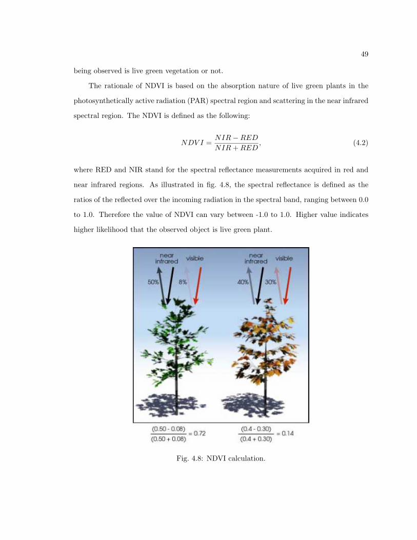
49
being observed is live green vegetation or not.
The rationale of NDVI is based on the absorption nature of live green plants in the
photosynthetically active radiation (PAR) spectral region and scattering in the near infrared
spectral region. The NDVI is defined as the following:
NDV I =NIR−REDNIR+RED
, (4.2)
where RED and NIR stand for the spectral reflectance measurements acquired in red and
near infrared regions. As illustrated in fig. 4.8, the spectral reflectance is defined as the
ratios of the reflected over the incoming radiation in the spectral band, ranging between 0.0
to 1.0. Therefore the value of NDVI can vary between -1.0 to 1.0. Higher value indicates
higher likelihood that the observed object is live green plant.
Fig. 4.8: NDVI calculation.
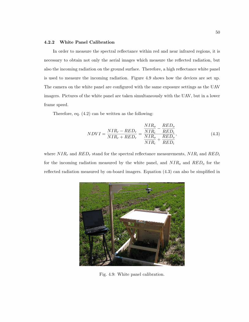
50
4.2.2 White Panel Calibration
In order to measure the spectral reflectance within red and near infrared regions, it is
necessary to obtain not only the aerial images which measure the reflected radiation, but
also the incoming radiation on the ground surface. Therefore, a high reflectance white panel
is used to measure the incoming radiation. Figure 4.9 shows how the devices are set up.
The camera on the white panel are configured with the same exposure settings as the UAV
imagers. Pictures of the white panel are taken simultaneously with the UAV, but in a lower
frame speed.
Therefore, eq. (4.2) can be written as the following:
NDV I =NIRr −REDr
NIRr +REDr=
NIRo
NIRi− REDo
REDi
NIRo
NIRi+REDo
REDi
, (4.3)
where NIRr and REDr stand for the spectral reflectance measurements, NIRi and REDi
for the incoming radiation measured by the white panel, and NIRo and REDo for the
reflected radiation measured by on-board imagers. Equation (4.3) can also be simplified in
Fig. 4.9: White panel calibration.

51
the following form:
NDV I =NIRo ×REDi −REDo ×NIRi
NIRo ×REDi +REDo ×NIRi. (4.4)
Notice that in eq. (4.4), if the values of the incoming radiation of near infrared and red
spectral region hold as a local constant, we can obtain the radio between the two, which is
also a constant. The radio is described as the following:
α =NIRi
REDi, (4.5)
where α is the radio between the incoming radiation of near infrared and red spectrum.
Insert eq. (4.5) to (4.4), we have:
NDV I =NIRo − α×REDo
NIRo + α×REDo. (4.6)
As a result, using eq. (4.6), we can obtain the NDVI value, without knowing the exact
incoming radiance in each pixel of the image. This method is very useful when large objects
create shade in the image (i.e., clouds). However, the assumption is made that this object
does not create or only absorb spectrum in red or near infrared band. The result of a NDVI
image is shown in fig. 4.10. Note that the grayscale color of the NDVI is mapped from its
original value range of [−1.0, 1.0] to integers between [0, 255].
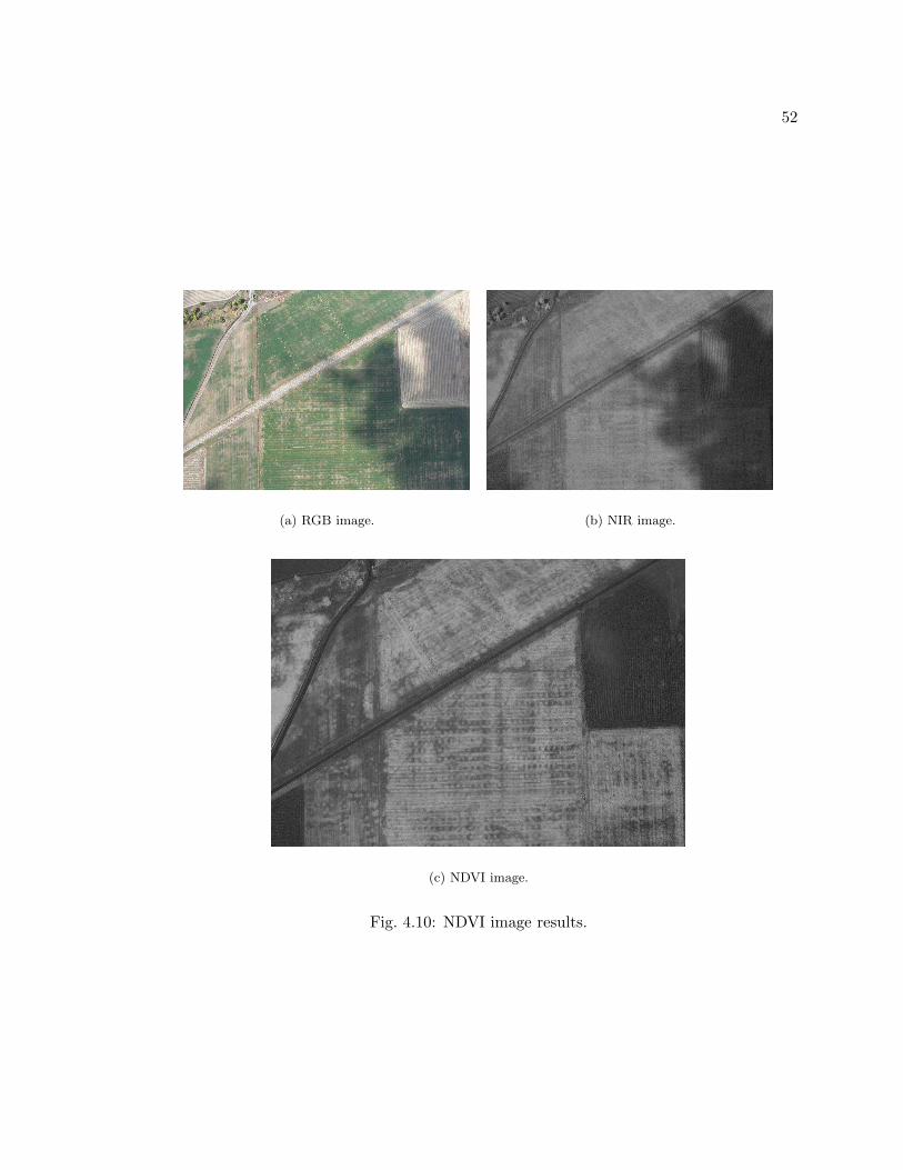
52
(a) RGB image. (b) NIR image.
(c) NDVI image.
Fig. 4.10: NDVI image results.

53
Chapter 5
Conclusion
5.1 Contribution
A multispectral imager based on AggieAir miniature Unmanned Aerial Vehicle is de-
signed and proven to work. Using some post image processing technologies, the multispec-
tral aerial images are utilized in a broad spectrum of applications. Below is a list of the
contributions presented in this thesis:
• AggieAir Architecture
– AggieAir Architecture planning and realization,
– 72 inches airframe flight tests support,
– Gumstix on-board computer implementation;
• GhostFoto multispectral imager
– Canon PowerShot SX100 IS/SX110 IS,
– Near infrared camera modification,
– Periodic capture function,
– State machine,
– Multithread architecture,
– Interthread communication and synchronization,
– Image geo-referencing,
– GhostEye logging function,
– GhostEye user interface,

54
– libgphoto2 implementation in OpenEmbedded Linux,
– GhostEye implementation under OpenEmbedded Linux;
• River tracking algorithm
– Water area detection with NIR image,
– Histogram-based river detection in NIR image,
– River flow estimation,
– Dynamic way point generation,
– River tracking simulation;
• NDVI image generation
– NDVI algorithm,
– White panel calibration,
– High resolution NDVI images.
5.2 Future Work
5.2.1 Thermal Infrared Camera
As addressed in sec. 1.1.2, thermal imaging is important for agricultural applications
[10, 11]. The Photon 320 uncooled TIR camera, shown in fig. 5.1, can be mounted on the
72 inches AggieAir UAV due to its small size and light weight.
However, a few problems still need to be addressed:
• Nonuniform temperature interpretation due to uncooled system,
• Difficulty in mounting the camera system and high fidelity video transmission,
• Difficulty in installing camera protection due to reflection of its own heat.

55
Fig. 5.1: Photon 320 uncool TIR camera.
5.2.2 Collaborative Remote Sensing
Collaborative remote sensing is based on multiple UAVs which are mounted with remote
sensing platforms. It is used in scenarios in which the users need to apply a group of UAVs
simultaneously to optimize the observation of distributed targets. Hence, a UAV group
needs to maintain a certain formation. The applications include remote stereo vision, 3D
geologic map modeling, etc.
The current pre-programmed fight plan can only provide an open-loop method for the
multi-UAV formation control, therefore collaborative remote sensing is not yet feasible in
the current platform. In order to implement the collaborative sensing technology, we need
to enable certain cross-UAV interoperability with which communication among multiple
UAVs can be realized, so that a close-loop multi-UAV formation control system can be
established. In addition, each UAV needs to determine its own position autonomously,
which means certain level of on-board real-time processing is required in such complex
multiple UAV navigation. The decision making could be based on many aspects, such as
ground and aerial targets, enviromental parameters, etc.
The implementation of the decision making system may involve technologies such as
machine vision, sensor fusion, etc. Therefore, the on-board computer systems need to be
powerful enough to handle the real-time signal and image processing computational stress.

56
5.2.3 Implementation of OpenJAUS
Joint Architecture for Unmanned Systems (JAUS) [28] is a comprehensive architecture
specified for Unmanned Systems (UMS) to provide interoperability among all supported
platforms. JAUS was originally developed for US military unmanned system, but it is an
ideal communication architecture for systems such as AggieAir. The critical data such as
aircraft attitudes or payload status can be transmitted among multiple UAVs and ground
control stations.
Coopmans and Han [22] addressed that to ensure interoperability among multiple
UAVs, the future AggieAir system needs to use OpenJAUS [29], which is a free and open-
source implementation of JAUS architecture. The implementation of OpenJAUS on Ag-
gieAir system is able to create a cross-UAV commanding and controlling link, which is
considered to be the first step to enable applications such as collaborative remote sensing
or multi-UAV formation control.
5.2.4 General-Purpose GPU-Based Image Processing
GPU, graphics processing unit, was initially developed to offload the 3D graphics ren-
dering from CPUs. It is designed with fully programmable vertex and pixel processing units
which are used for creating more realistic 3D graphics. Architecturally GPUs are highly
parallel streaming processors optimized for vector operations, coupled with tremendous
memory bandwidth.
The idea of general-purpose computation on GPUs (GPGPU) is to utilize this compu-
tational power for algorithms that require intense computation and are able to be processed
in parallel. Image processing, for example, is a major application that can be shifted from
common CPU computation to GPU and achieve enormous performance gain, normally with
hundreds of times speedup than the sequential CPU implementations.
Therefore, in order to enable on-board real-time image processing on the UAV hard-
ware, an embedded GPU is required. In addition, on the software achitecture, to imple-
ment the image processing algorithms requires embedded GPU libraries or programming

57
models [30], with which programmers can easily access the GPU streaming processor and
implement their image processing algorithms.

58
References
[1] E. Pastor, J. Lopez, and P. Royo, “UAV payload and mission control hardware/softwarearchitecture,” IEEE Aerospace and Electronic Systems Magazine, vol. 22, pp. 3–8, June2007.
[2] H. Chao, Y. Cao, and Y. Chen, “Autopilots for small fixed wing unmanned air vehi-cles: a survey,” in Proceedings of IEEE International Conference on Mechatronics andAutomation, pp. 3144–3149, Aug. 2007.
[3] UAVnet, “European Civil UAV Roadmap,” http://www.uavnet.com/, 2005.
[4] D. Casbeer, R. Beard, T. McLain, S. Li, and R. Mehra, “Forest fire monitoring withmultiple small UAVs,” in Proceedings of 2005 American Control Conference, pp. 3530–3535, June 2005.
[5] L. Johnson, S. Herwitz, B. Lobitz, and S. Dunagan, “Feasibility of monitoring coffeefield ripeness with airborne multispectral imagery,” Applied Engineering in Agriculture,vol. 20, pp. 845–850, June 2004.
[6] S. Herwitz, L. Johnson, S. Dunagan, R. Higgins, D. Sullivan, J. Zheng, B. Lobitz,J. Leung, B. Gallmeyer, M. Aoyagi, R. Slye, and J. Brass, “Imaging from an un-manned aerial vehicle: agricultural surveillance and decision support,” Computers andElectronics in Agriculture, vol. 44, pp. 49–61, May 2004.
[7] E. R. Hunt, C. L. Walthall, and C. S. T. Daughtry, “High-resolution multispectraldigital photography using unmanned airborne vehicles [abstract],” in 20th Biennialworkshop on Areal Photography, Videography, and High Resolution Digital Imagery forResource Assessment, Oct. 2005.
[8] K. Kaaniche, B. Champion, C. Pegard, and P. Vasseur, “A vision algorithm for dy-namic detection of moving vehicles with a UAV,” in Proceedings of IEEE InternationalConference on Robotics and Automation, pp. 1878–1883, Apr. 2005.
[9] E. Frew, T. McGee, Z. Kim, X. Xiao, S. Jackson, M. Morimoto, S. Rathinam, J. Padial,and R. Sengupta, “Vision-based road-following using a small autonomous aircraft,” inProceedings of IEEE Aerospace Conference, pp. 3006–3015, May 2004.
[10] P. J. Pinter, Jr., J. L. Hatfield, J. S. Schepers, E. M. Barnes, M. S. Moran, C. S. Daugh-try, and D. R. Upchurch, “Remote sensing for crop management,” PhotogrammetricEngineering and Remote Sensing, vol. 69, pp. 647–664, June 2003.
[11] J. A. J. Berni, P. J. Zarco-Tejada, L. Suarez, and E. Fereres, “Thermal and narrow-band multispectral remote sensing for vegetation monitoring from an unmanned aerialvehicle,” IEEE Transactions on Geoscience and Remote Sensing, vol. 47, pp. 722–738,Mar. 2009.
59
[12] Y. Wang, A. Camargo, R. Fevig, F. Martel, and R. Schultz, “Image mosaicking fromuncooled thermal IR video captured by a small UAV,” Image Analysis and Interpre-tation, vol. 24-26, pp. 161–164, Mar. 2008.
[13] H. Chao, M. Baumann, A. Jensen, Y. Chen, Y. Cao, W. Ren, and M. McKee,“Band-reconfigurable multi-UAV-based cooperative remote sensing for real-time watermanagement and distributed irrigation control,” in Proceedings of 17th IFAC WorldCongress, pp. 11 744–11 749, July 2008.
[14] A. Jensen, M. Baumann, and Y. Chen, “Low-cost multispectral aerial imaging usingautonomous runway-free small flying wing vehicles,” in IEEE International Geoscienceand Remote Sensing Symposium, pp. 506–509, Oct. 2007.
[15] M. Baumann, “Imager development and image processing for small UAV-based real-time multispectral remote sensing,” Master’s thesis, University of Applied SciencesRavensburg-Weingarten and Utah State University, Logan, 2007.
[16] A. Jensen, “gRAID: A geospatial real-time aerial image display for a low-cost au-tonomous multispectral remote sensing platform (AggieAir),” Master’s thesis, UtahState University, Logan, 2009.
[17] I. Savin, D. Stathakis, T. Negre, and V. Isaev, “Prediction of crop yields with the useof neural networks,” Russian Agricultural Sciences, vol. 33, pp. 11–14, Dec. 2007.
[18] J. O. Adegoke and A. M. Carleton, “Relations between soil moisture and satellitevegetation indices in the U.S. corn belt,” American Meteorological Society, vol. 3, pp.395–405, Apr. 2002.
[19] J. T. Kerr and M. Ostrovsky, “From space to species: ecological applications for remotesensing,” Trends in Ecology and Evolution, vol. 18, pp. 299–305, May 2003.
[20] “Paparazzi the Free Autopilot,” http://paparazzi.enac.fr/wiki/Main Page, 2009.
[21] “Twog v1,” http://paparazzi.enac.fr/wiki/Twog v1, 2008.
[22] C. Coopmans and Y. Han, “AggieAir: An integrated and effective small multi-UAVcommand and data collection architecture,” in Proceedings of ASME 2009 InternationalDesign Engineering Technical Conferences, Sept. 2009.
[23] “BULLET2HP Datasheet,” http://www.ubnt.com/downloads/b2hp datasheet.pdf, 2009.
[24] “NASA World Wind,” http://worldwind.arc.nasa.gov/, 2006.
[25] “Canon PowerShot SX100 IS,” http://www.usa.canon.com/, 2009.
[26] “gPhoto Home,” http://www.gphoto.org/, 2009.
[27] “libgphoto2: supported cameras,” http://www.gphoto.org/proj/libgphoto2/support.php, 2009.

60
[28] “JAUS compliance specification,” http://www.jauswg.org/archive/archive.shtml, 2005.
[29] “OpenJAUS - JAUS Robotics Software Development Kit,”http://www.openjaus.com/, 2008.
[30] “CUDA - Compute Unified Device Architecture,”http://www.nvidia.com/object/cuda home.html#, 2009.