an autonomous mobile manipulator for assembly tasks · an autonomous mobile manipulator for...
TRANSCRIPT
Auton Robot (2010) 28: 131–149DOI 10.1007/s10514-009-9142-y
An autonomous mobile manipulator for assembly tasks
Brad Hamner · Seth Koterba · Jane Shi ·Reid Simmons · Sanjiv Singh
Received: 22 January 2009 / Accepted: 13 August 2009 / Published online: 1 September 2009© Springer Science+Business Media, LLC 2009
Abstract The fundamental difference between autonomousrobotic assembly and traditional hard automation, currentlyutilized in large-scale manufacturing production, lies in thespecific approaches used in locating, acquiring, manipulat-ing, aligning, and assembling parts. An autonomous roboticassembly manipulator offers high flexibility and high ca-pability to deal with the inherent system uncertainties, un-knowns, and exceptions. This paper presents an autonomousmobile manipulator that effectively overcomes inherent sys-tem uncertainties and exceptions by utilizing control strate-gies that employ coordinated control, combine visual andforce servoing, and incorporate sophisticated reactive taskcontrol. The mobile manipulation system has been demon-strated experimentally to achieve high reliability for a “peg-in-hole” type of insertion assembly task that is commonlyencountered in automotive wiring harness assembly.
Keywords Mobile manipulation · Coordinated control ·Constrained motion · Task architecture
B. Hamner (�) · S. Koterba · R. Simmons · S. SinghCarnegie Mellon University, 5000 Forbes Ave., Pittsburgh,PA 15213, USAe-mail: [email protected]
S. Koterbae-mail: [email protected]
R. Simmonse-mail: [email protected]
S. Singhe-mail: [email protected]
J. ShiResearch and Development Center, Manufacturing SystemsResearch Lab., General Motors Company, 30500 Mound Road,Warren, MI 48090, USAe-mail: [email protected]
1 Introduction
Across many domains, there is increasing demand for ro-bots capable of performing complex and dexterous manipu-lation tasks. A prominent example is the need for automatedassembly. From terrestrial applications, such as factory as-sembly lines, to extraterrestrial scenarios, such as automatedassembly of lunar habitats, robotic manipulation is, and willbe, integral. While robotic assets currently perform manytasks, especially in factory settings, these tasks are typi-cally highly structured. In other words, the tasks and robotsare designed such that minimally sophisticated technologycan achieve success. Often, hardware and software are de-signed for a very specific task. Looking ahead, future robotsmay assume a variety of duties, from transporting payloadsacross large workspaces to precise insertion or placementof small components. The tasks will be highly variable andcomplex. With the combination of a dexterous manipulatorand a mobile base, mobile manipulators are well suited tothese complex assembly tasks.
Although mobile manipulators provide the mobility anddexterity to meet the challenges of assembly tasks, sensorsand software play a critical role in achieving successful re-sults. Given any complex scenario, the mobile manipulatormust be able to sense its environment, make decisions basedon the configuration of the environment, and correctly per-form actions informed by those decisions.
In this paper we present work on an advanced mobile ma-nipulator capable of performing assembly tasks in the do-main of automotive manufacturing. First, we describe ourcontroller, which coordinates the motion of the mobile baseand manipulator to achieve desired end-effector poses whilemaintaining high manipulability. Then, we present compet-ing control schemes that use differing combinations of vi-sual servoing and force control, and compare the schemes
132 Auton Robot (2010) 28: 131–149
in their abilities to perform a tight-tolerance “peg-in-hole”type of insertion assembly task. We define a framework forconstraining the end-effector of a manipulator based on po-sition and/or force using a high-frequency, low-level con-troller, and combine this with a sophisticated task-level ex-ecutive. Finally, we demonstrate the capability of the systemwith results from repeated experiments of the insertion taskon an automotive task board. The results show that we canachieve these tight-tolerance assembly tasks with high reli-ability and robustness to error with the robot starting fromvarying, unknown positions.
2 Overview of approach and related work
Our research goal is to perform sophisticated assembly tasksautonomously. To achieve this, we have developed an au-tonomous mobile manipulator that effectively overcomesinherent system uncertainties and exceptions, with a highdegree of performance and reliability, by utilizing controlstrategies that employ coordinated control of the base andmanipulator, combine visual and force servoing, and incor-porate sophisticated reactive task-level control. Coordina-tion of the mobile base and manipulator increases the rangeof the manipulator. The combination of visual and force ser-voing increases the performance of the system beyond thatof a system which uses either method alone. Task-level con-trol provides an architecture for flexible and reliable task ex-ecution. In the following subsections, we discuss these threeaspects of our approach that enable high-performance andreliable mobile manipulation, as well as related approaches.
2.1 Coordinated control of base and manipulator
Task flexibility and robotic mobility are two main advan-tages that mobile manipulators can bring to manufacturingassembly applications. Compared with traditional industrialrobots, it is easier for mobile manipulators to adapt to chang-ing environments and perform a variety of assembly tasks.By placing the manipulator on a mobile base, the robot cantravel between the work area and parts feeder and can followmoving assembly lines.
Early work in mobile manipulation often treated the mo-bile base and the manipulator as two independent robots.Shin et al. demonstrated the limitations of this approach andthe need for coordination. They developed a system that em-ploys decoupled motion of the mobile manipulator (Shin etal. 2003). Decoupled motion describes motion in which thebase remains fixed while the manipulator moves. This al-lows for high tracking accuracy of the end effector, but takeslonger for tasks to be accomplished as tracking must be in-terrupted to allow for repositioning of the base. The planner
used chooses base positions to optimize the arm’s manipu-lability in the direction of the desired trajectory while mini-mizing the number of times the base is required to reposition(Shin et al. 2003).
In the context of coordination of mobile bases and ma-nipulators, many authors have contributed to the literature.The majority of contributions perform coordination in termsof dynamics, i.e. controlling forces and torques rather thanpositions and velocities, a technique that differs from ourkinematic approach. Some of these authors have investi-gated internal control in this dynamic context. For exam-ple, Yamamoto and Yun described a dynamic coordinatedcontroller in which the end-effector is constrained to fol-low a trajectory while the base is controlled to maintain armmanipulability when possible (Yamamoto and Yun 1992).Similarly, Holmberg and Khatib defined a dynamically de-coupled model of control to achieve smooth, precise controlof a mobile base (Holmberg and Khatib 2000). This workseeks to minimize forces on a mobile base, called a poweredcaster vehicle, while producing and maintaining desired co-ordinated motion. Kim et al. present a coordinated controlscheme that uses the null space of an overactuated mobilemanipulator to achieve dynamically stable motion (Kim etal. 2002).
Although it is not explicitly dealt with in our currentexperimental scenario, avoiding obstacles is an importantcapability of mobile manipulators in manufacturing andassembly. A manipulator may have to reach around, orthrough, already-assembled components to achieve its task.Also, in addition to extending the range of the manipulator,the addition of a mobile base adds kinematic redundancy,which allows the robot to avoid obstacles while complet-ing tasks efficiently. Brock and Khatib defined the elasticstrips framework in which a dynamic planner allows themobile manipulator to move through a tunnel of free space(Brock and Khatib 2002). The controller tracks a desiredend-effector path while keeping the manipulator’s joints andthe base away from obstacles. This is achieved by generatingprotective hulls, which are constructed to ensure that neitherthe base nor the arm will collide with any obstacles duringtrajectory following. Without using a planner, a controllerlike the one presented in Sciavicco and Siciliano (2005) canuse the null space of the manipulator’s Jacobian to keep thejoints away from obstacles. Our controller uses this controlscheme, with the exception that we use the null space toachieve a higher manipulability (see Sect. 4).
2.2 Combining visual and force servoing
In the domain of robotic assembly, the critical portion of acontrol task is the physical mating of components. We usevisual servoing and force servoing together in a manner thatimproves the system robustness, without the need for highly
Auton Robot (2010) 28: 131–149 133
accurate visual sensing or precisely known global referencecoordinates. The visual servoing is used to bring the end-effector of the mobile manipulator to a rough alignment in agross area of the assembly location. Hybrid control of poseand force (as detailed in Sect. 5) enables the mobile manip-ulator to overcome the geometric location uncertainty fromvisual servoing to contact the task board and complete thepeg-in-hole assembly at a precise location, with tight toler-ance.
Mason (1979) laid the foundation for the earliest pose/force control work by defining the constraint frame based onnatural constraints (rigid objects in the space) and artificialconstraints (desired positions or forces on the end-effector).Raibert and Craig (1981) defined a hybrid pose/force con-trol scheme based on these descriptions. They run sepa-rate, decoupled pose and force controllers. Each dimen-sion of the constraint frame is controlled by at most oneof the controllers, not both. By decoupling the problem inthis way, they ensure that the force constraints and poseconstraints do not work at odds with one another. The re-sults of the two controllers are summed and then convertedinto commands for the manipulator’s joints via inverse kine-matics. Yoshikawa (1987) built on this formulation, but ex-tended it to incorporate the dynamics of the manipulator.He went on to show that if the dynamic models are cor-rect, it can be proven that both desired pose and force can beachieved. Mills and Goldenberg (1989) also take a dynamicsapproach. However, they linearize the dynamics equationslocally to ease computation. Their method requires an ex-plicit definition of the constraint surface, but the controlleroperates in the task space of the end-effector, rather thanrequiring a separate constraint space, as in the earlier meth-ods.
In more recent work, the domain of assistive robotics pro-vides many of the same challenges as in mobile assembly.A robot working with humans may be tasked to search forand track objects whose locations are not known a priori,and may have to pick up, carry, and place objects (Schaal2007 presents an extensive summary of the challenges ofrobots operating in human environments). Similarly, a robotoperating on a mobile assembly line must be able to acquirea part, locate, track, and approach the piece undergoing as-sembly, and perform the assembly operation. Service robotsalso have the added difficulty of needing to appear friendlyand operate smoothly in environments designed for humanswithout consideration for robots. Industrial robots have nosuch restrictions, but the precision of the pickup and placetasks is higher. Depending on the part being assembled, al-lowable position error may be measured in millimeters, andthe orientation may have to be nearly perfect (to plug in anelectronic component, for example).
In service and industrial robotics, the requirements ofworking in a large area, yet being able to grasp objects, lends
itself to the use of mobile manipulators with many-degree-of-freedom arms. Bischoff developed the humanoid robotHERMES as a flexible, mobile, and dependable platformfor assistive robotics (Bischoff 1997). Petersson et al. de-scribe a system in which a mobile manipulator must detect,approach, and pick up an item from a previously-unknownlocation. An emphasis is placed on integrating sensing, plan-ning, and control to achieve the task at hand (Petersson et al.2002). Dillman et al. also study pickup and placement withmobile manipulators, on command from humans, doing soin human-friendly environments (Dillman et al. 2002).
Force feedback and force control have been used in bothservice and industrial robotics. Peshkin et al. developed theCobot, a collaborative robot for assisting human operatorswith heavy lifting and control of heavy objects in manu-facturing and assembly tasks. They define a virtual surfacealong which to move an assembly. As the operator pushesthe assembly, the machine prevents its motion past the sur-face, instead applying resistive force normal to the surfaceand allowing it to slide along the surface, as if the assemblywere on a smooth rail in the direction of the intended mo-tion (Peshkin et al. 2000). Duchaine and Gosselin use im-pedance control to let a human control a manipulator, wherethe force being applied to the robot by an operator is readas intention for the end-effector to move in a particular di-rection (Duchaine and Gosselin 2007). They implement avelocity controller to achieve the smooth motion necessarywhen working with a human in the loop.
Force feedback may be used to sense objects where othersensors cannot be as precise. Kragic et al. also working inthe domain of service robotics, use tactile sensing to accountfor visual servo inaccuracy (Kragic et al. 2003). During agrasp task, a visual servo moves a gripper hand close to theobject to be grasped. When the hand makes contact with theobject, the robot re-centers the hand about the point of con-tact. This is similar to our scheme, presented below, in whicha visual servo alignment moves the gripper close enoughto begin using force feedback to feel for a target. Edsingerand Kemp use force sensing in multiple ways (Edsingerand Kemp 2006). One way is similar to that of Kragic, inthat force feedback provides assurance that the object to begrasped is indeed being grasped, as well as some informa-tion on the diameter of the object. Force information is alsoused to augment possibly inaccurate visual information. Forinstance, when placing an object, the robot feels to get a pre-cise location for a shelf whose initial position comes fromfiducials detected by a camera. As presented below, we usea similar scheme to find the task board and target hole in ourassembly task after rough alignment using fiducials.
Our implementation of the assembly task requires added,known structure to the environment (ARTag fiducials) to aidin localization. However, this may not be possible in all sit-uations. To extend our work to more scenarios, we expect
134 Auton Robot (2010) 28: 131–149
to use a localization algorithm that makes use of the existingstructure in the environment. For instance, Se et al. have pro-posed a global localization method that uses SIFT featuresto build local maps, which are then merged and integratedwith a global map (Se et al. 2005).
2.3 Reactive task control
In order to be deployed in manufacturing and assembly en-vironments, mobile manipulators must have extremely highperformance and be able to deal with system uncertainty anderrors autonomously. Reliability in task execution is crit-ical, since the environment is rarely exactly the same be-tween runs, and errors are frequent. To achieve complex as-sembly operations reliably, sophisticated, reactive task-levelcontrol is required. The reactive task-level control frame-work decomposes high-level tasks into subtasks. An execu-tive then sequences the subtasks, dispatches them, and mon-itors their execution. The executive can react to contingen-cies, retrying subtasks or removing them from the queue andattempting a different approach, as it deems necessary. Ourapproach uses the executive developed for the Syndicate ar-chitecture (Sellner et al. 2006), which extends the 3T archi-tecture (Bonasso et al. 1997) in that each robotic agent runsan executive that detects errors and exceptions and modifiesan intended schedule of tasks to ensure completion of themain goal.
Effective error detection and recovery is one of severaltechniques that can increase task execution reliability androbustness. Donald (1990) studied the planning aspect of er-ror detection and recovery methods for robotic peg-in-holeassembly. He uses a geometry model to enumerate a varietyof assembly failure conditions of a given peg-in-hole assem-bly task for presumed system uncertainties, and then planseither a single or multi-step motion strategy to deal withthose assembly failures in the task execution. The methodis based on a “push-forwards” algorithm and “failure modeanalysis” to plan a motion region for a trial-and-error moveto improve the assembly robustness. The strength of thetechnique is the comprehensive analysis of system uncer-tainties and their synthesis. The weakness is that it is ex-tremely hard to program a general solution of recovery forall possible failures that have been anticipated at the designstage.
Recently, De Schutter et al. (2007) generalized a taskspecification approach, called constraint-based program-ming, to specify sensor-based manipulation tasks by assign-ing control modes and associated constraints to arbitrarydirections in the six dimensional manipulation space. Asdescribed in Sect. 5, we have adopted a similar approachwith constrained motion primitives and their associated con-straints. The main concept is to specify a general error re-covery for an assembly task by utilizing a set of constraints.
With the knowledge of a single constraint violation, or vi-olations of various constraint combinations, the user canprogram an error recovery decision based on experimen-tal results and observations. Thus, reactive task control canbe realized by implementing recovery procedures for differ-ent failure conditions in the executive layer, as detailed inSect. 6.
3 Application and experimental system
This section details the application scenario that we are tack-ling and the mobile manipulator that we designed, whichwas used for the experiments.
3.1 Application scenario
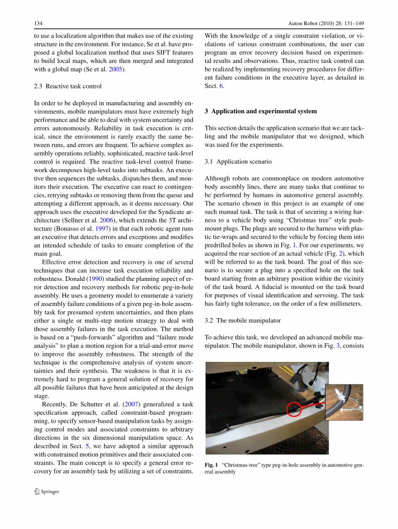
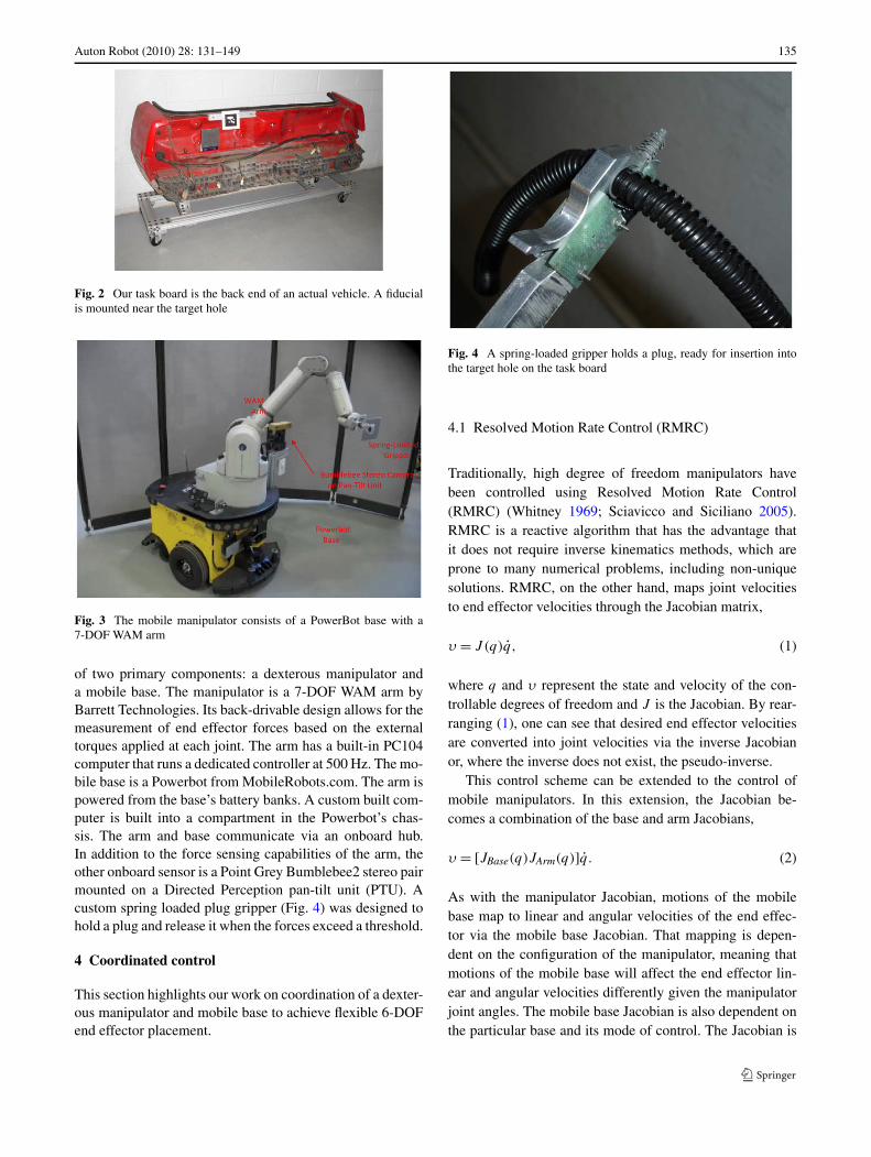
Although robots are commonplace on modern automotivebody assembly lines, there are many tasks that continue tobe performed by humans in automotive general assembly.The scenario chosen in this project is an example of onesuch manual task. The task is that of securing a wiring har-ness to a vehicle body using “Christmas tree” style push-mount plugs. The plugs are secured to the harness with plas-tic tie-wraps and secured to the vehicle by forcing them intopredrilled holes as shown in Fig. 1. For our experiments, weacquired the rear section of an actual vehicle (Fig. 2), whichwill be referred to as the task board. The goal of this sce-nario is to secure a plug into a specified hole on the taskboard starting from an arbitrary position within the vicinityof the task board. A fiducial is mounted on the task boardfor purposes of visual identification and servoing. The taskhas fairly tight tolerance, on the order of a few millimeters.
3.2 The mobile manipulator
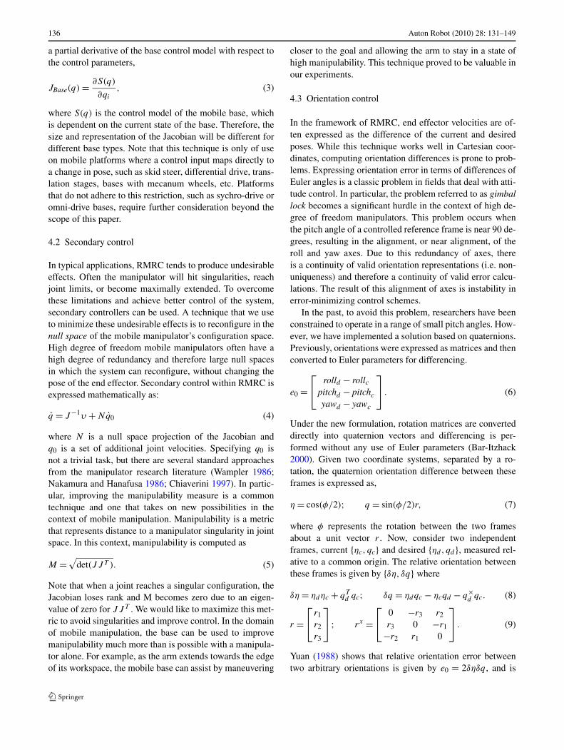
To achieve this task, we developed an advanced mobile ma-nipulator. The mobile manipulator, shown in Fig. 3, consists
Fig. 1 “Christmas-tree” type peg-in-hole assembly in automotive gen-eral assembly
Auton Robot (2010) 28: 131–149 135
Fig. 2 Our task board is the back end of an actual vehicle. A fiducialis mounted near the target hole
Fig. 3 The mobile manipulator consists of a PowerBot base with a7-DOF WAM arm
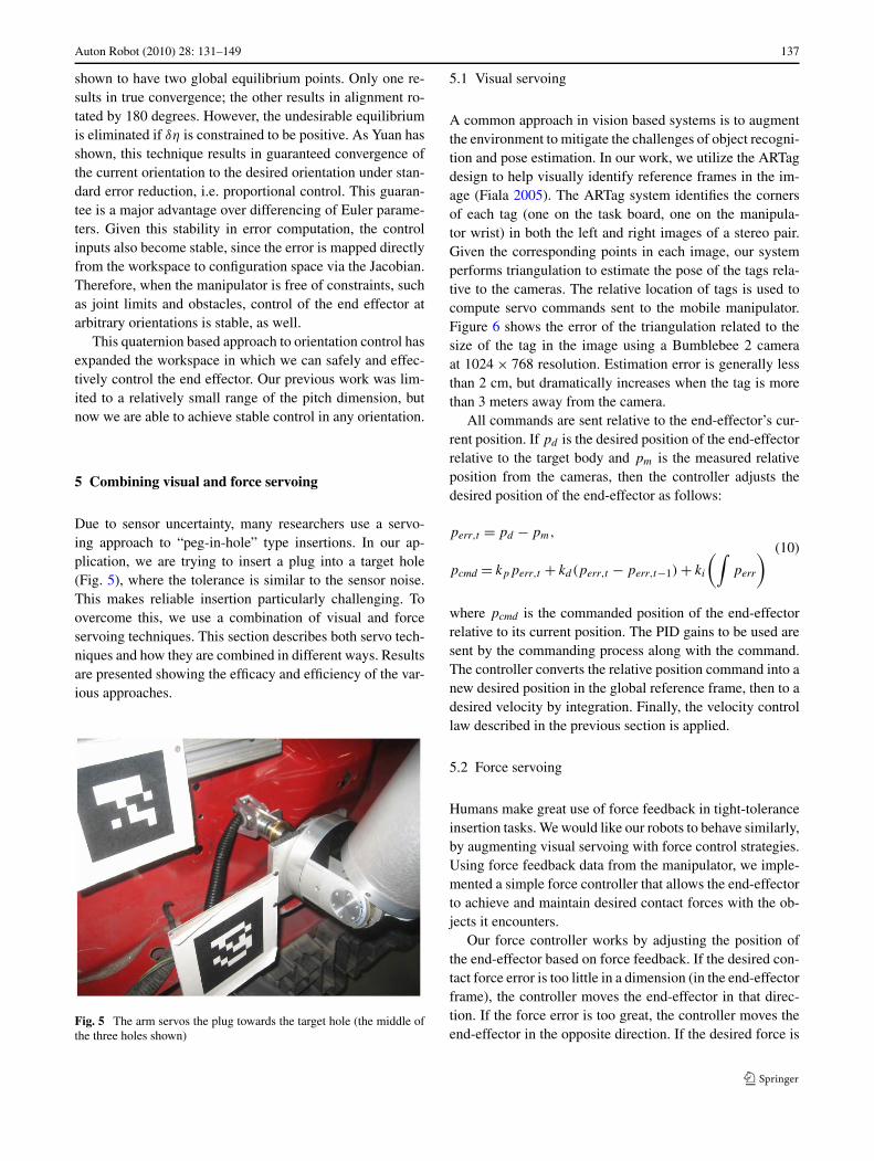
of two primary components: a dexterous manipulator anda mobile base. The manipulator is a 7-DOF WAM arm byBarrett Technologies. Its back-drivable design allows for themeasurement of end effector forces based on the externaltorques applied at each joint. The arm has a built-in PC104computer that runs a dedicated controller at 500 Hz. The mo-bile base is a Powerbot from MobileRobots.com. The arm ispowered from the base’s battery banks. A custom built com-puter is built into a compartment in the Powerbot’s chas-sis. The arm and base communicate via an onboard hub.In addition to the force sensing capabilities of the arm, theother onboard sensor is a Point Grey Bumblebee2 stereo pairmounted on a Directed Perception pan-tilt unit (PTU). Acustom spring loaded plug gripper (Fig. 4) was designed tohold a plug and release it when the forces exceed a threshold.
4 Coordinated control
This section highlights our work on coordination of a dexter-ous manipulator and mobile base to achieve flexible 6-DOFend effector placement.
Fig. 4 A spring-loaded gripper holds a plug, ready for insertion intothe target hole on the task board
4.1 Resolved Motion Rate Control (RMRC)
Traditionally, high degree of freedom manipulators havebeen controlled using Resolved Motion Rate Control(RMRC) (Whitney 1969; Sciavicco and Siciliano 2005).RMRC is a reactive algorithm that has the advantage thatit does not require inverse kinematics methods, which areprone to many numerical problems, including non-uniquesolutions. RMRC, on the other hand, maps joint velocitiesto end effector velocities through the Jacobian matrix,
υ = J (q)q̇, (1)
where q and υ represent the state and velocity of the con-trollable degrees of freedom and J is the Jacobian. By rear-ranging (1), one can see that desired end effector velocitiesare converted into joint velocities via the inverse Jacobianor, where the inverse does not exist, the pseudo-inverse.
This control scheme can be extended to the control ofmobile manipulators. In this extension, the Jacobian be-comes a combination of the base and arm Jacobians,
υ = [JBase(q)JArm(q)]q̇. (2)
As with the manipulator Jacobian, motions of the mobilebase map to linear and angular velocities of the end effec-tor via the mobile base Jacobian. That mapping is depen-dent on the configuration of the manipulator, meaning thatmotions of the mobile base will affect the end effector lin-ear and angular velocities differently given the manipulatorjoint angles. The mobile base Jacobian is also dependent onthe particular base and its mode of control. The Jacobian is
136 Auton Robot (2010) 28: 131–149
a partial derivative of the base control model with respect tothe control parameters,
JBase(q) = ∂S(q)
∂qi
, (3)
where S(q) is the control model of the mobile base, whichis dependent on the current state of the base. Therefore, thesize and representation of the Jacobian will be different fordifferent base types. Note that this technique is only of useon mobile platforms where a control input maps directly toa change in pose, such as skid steer, differential drive, trans-lation stages, bases with mecanum wheels, etc. Platformsthat do not adhere to this restriction, such as sychro-drive oromni-drive bases, require further consideration beyond thescope of this paper.
4.2 Secondary control
In typical applications, RMRC tends to produce undesirableeffects. Often the manipulator will hit singularities, reachjoint limits, or become maximally extended. To overcomethese limitations and achieve better control of the system,secondary controllers can be used. A technique that we useto minimize these undesirable effects is to reconfigure in thenull space of the mobile manipulator’s configuration space.High degree of freedom mobile manipulators often have ahigh degree of redundancy and therefore large null spacesin which the system can reconfigure, without changing thepose of the end effector. Secondary control within RMRC isexpressed mathematically as:
q̇ = J−1υ + Nq̇0 (4)
where N is a null space projection of the Jacobian andq0 is a set of additional joint velocities. Specifying q0 isnot a trivial task, but there are several standard approachesfrom the manipulator research literature (Wampler 1986;Nakamura and Hanafusa 1986; Chiaverini 1997). In partic-ular, improving the manipulability measure is a commontechnique and one that takes on new possibilities in thecontext of mobile manipulation. Manipulability is a metricthat represents distance to a manipulator singularity in jointspace. In this context, manipulability is computed as
M =√
det(JJ T ). (5)
Note that when a joint reaches a singular configuration, theJacobian loses rank and M becomes zero due to an eigen-value of zero for JJ T . We would like to maximize this met-ric to avoid singularities and improve control. In the domainof mobile manipulation, the base can be used to improvemanipulability much more than is possible with a manipula-tor alone. For example, as the arm extends towards the edgeof its workspace, the mobile base can assist by maneuvering
closer to the goal and allowing the arm to stay in a state ofhigh manipulability. This technique proved to be valuable inour experiments.
4.3 Orientation control
In the framework of RMRC, end effector velocities are of-ten expressed as the difference of the current and desiredposes. While this technique works well in Cartesian coor-dinates, computing orientation differences is prone to prob-lems. Expressing orientation error in terms of differences ofEuler angles is a classic problem in fields that deal with atti-tude control. In particular, the problem referred to as gimballock becomes a significant hurdle in the context of high de-gree of freedom manipulators. This problem occurs whenthe pitch angle of a controlled reference frame is near 90 de-grees, resulting in the alignment, or near alignment, of theroll and yaw axes. Due to this redundancy of axes, thereis a continuity of valid orientation representations (i.e. non-uniqueness) and therefore a continuity of valid error calcu-lations. The result of this alignment of axes is instability inerror-minimizing control schemes.
In the past, to avoid this problem, researchers have beenconstrained to operate in a range of small pitch angles. How-ever, we have implemented a solution based on quaternions.Previously, orientations were expressed as matrices and thenconverted to Euler parameters for differencing.
e0 =⎡
⎣rolld − rollc
pitchd − pitchc
yawd − yawc
⎤
⎦ . (6)
Under the new formulation, rotation matrices are converteddirectly into quaternion vectors and differencing is per-formed without any use of Euler parameters (Bar-Itzhack2000). Given two coordinate systems, separated by a ro-tation, the quaternion orientation difference between theseframes is expressed as,
η = cos(φ/2); q = sin(φ/2)r, (7)
where φ represents the rotation between the two framesabout a unit vector r . Now, consider two independentframes, current {ηc, qc} and desired {ηd, qd}, measured rel-ative to a common origin. The relative orientation betweenthese frames is given by {δη, δq} where
δη = ηdηc + qTd qc; δq = ηdqc − ηcqd − q×
d qc. (8)
r =⎡
⎣r1
r2
r3
⎤
⎦ ; rx =⎡
⎣0 −r3 r2
r3 0 −r1
−r2 r1 0
⎤
⎦ . (9)
Yuan (1988) shows that relative orientation error betweentwo arbitrary orientations is given by e0 = 2δηδq , and is
Auton Robot (2010) 28: 131–149 137
shown to have two global equilibrium points. Only one re-sults in true convergence; the other results in alignment ro-tated by 180 degrees. However, the undesirable equilibriumis eliminated if δη is constrained to be positive. As Yuan hasshown, this technique results in guaranteed convergence ofthe current orientation to the desired orientation under stan-dard error reduction, i.e. proportional control. This guaran-tee is a major advantage over differencing of Euler parame-ters. Given this stability in error computation, the controlinputs also become stable, since the error is mapped directlyfrom the workspace to configuration space via the Jacobian.Therefore, when the manipulator is free of constraints, suchas joint limits and obstacles, control of the end effector atarbitrary orientations is stable, as well.
This quaternion based approach to orientation control hasexpanded the workspace in which we can safely and effec-tively control the end effector. Our previous work was lim-ited to a relatively small range of the pitch dimension, butnow we are able to achieve stable control in any orientation.
5 Combining visual and force servoing
Due to sensor uncertainty, many researchers use a servo-ing approach to “peg-in-hole” type insertions. In our ap-plication, we are trying to insert a plug into a target hole(Fig. 5), where the tolerance is similar to the sensor noise.This makes reliable insertion particularly challenging. Toovercome this, we use a combination of visual and forceservoing techniques. This section describes both servo tech-niques and how they are combined in different ways. Resultsare presented showing the efficacy and efficiency of the var-ious approaches.
Fig. 5 The arm servos the plug towards the target hole (the middle ofthe three holes shown)
5.1 Visual servoing
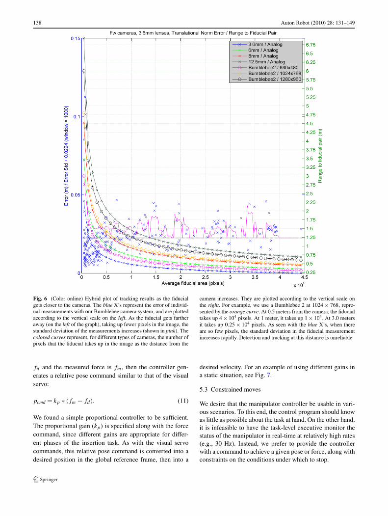
A common approach in vision based systems is to augmentthe environment to mitigate the challenges of object recogni-tion and pose estimation. In our work, we utilize the ARTagdesign to help visually identify reference frames in the im-age (Fiala 2005). The ARTag system identifies the cornersof each tag (one on the task board, one on the manipula-tor wrist) in both the left and right images of a stereo pair.Given the corresponding points in each image, our systemperforms triangulation to estimate the pose of the tags rela-tive to the cameras. The relative location of tags is used tocompute servo commands sent to the mobile manipulator.Figure 6 shows the error of the triangulation related to thesize of the tag in the image using a Bumblebee 2 cameraat 1024 × 768 resolution. Estimation error is generally lessthan 2 cm, but dramatically increases when the tag is morethan 3 meters away from the camera.
All commands are sent relative to the end-effector’s cur-rent position. If pd is the desired position of the end-effectorrelative to the target body and pm is the measured relativeposition from the cameras, then the controller adjusts thedesired position of the end-effector as follows:
perr,t = pd − pm,(10)
pcmd = kpperr,t + kd(perr,t − perr,t−1) + ki
(∫perr
)
where pcmd is the commanded position of the end-effectorrelative to its current position. The PID gains to be used aresent by the commanding process along with the command.The controller converts the relative position command into anew desired position in the global reference frame, then to adesired velocity by integration. Finally, the velocity controllaw described in the previous section is applied.
5.2 Force servoing
Humans make great use of force feedback in tight-toleranceinsertion tasks. We would like our robots to behave similarly,by augmenting visual servoing with force control strategies.Using force feedback data from the manipulator, we imple-mented a simple force controller that allows the end-effectorto achieve and maintain desired contact forces with the ob-jects it encounters.
Our force controller works by adjusting the position ofthe end-effector based on force feedback. If the desired con-tact force error is too little in a dimension (in the end-effectorframe), the controller moves the end-effector in that direc-tion. If the force error is too great, the controller moves theend-effector in the opposite direction. If the desired force is
138 Auton Robot (2010) 28: 131–149
Fig. 6 (Color online) Hybrid plot of tracking results as the fiducialgets closer to the cameras. The blue X’s represent the error of individ-ual measurements with our Bumblebee camera system, and are plottedaccording to the vertical scale on the left. As the fiducial gets fartheraway (on the left of the graph), taking up fewer pixels in the image, thestandard deviation of the measurements increases (shown in pink). Thecolored curves represent, for different types of cameras, the number ofpixels that the fiducial takes up in the image as the distance from the
camera increases. They are plotted according to the vertical scale onthe right. For example, we use a Bumblebee 2 at 1024 × 768, repre-sented by the orange curve. At 0.5 meters from the camera, the fiducialtakes up 4 × 104 pixels. At 1 meter, it takes up 1 × 10⁴. At 3.0 metersit takes up 0.25 × 104 pixels. As seen with the blue X’s, when thereare so few pixels, the standard deviation in the fiducial measurementincreases rapidly. Detection and tracking at this distance is unreliable
fd and the measured force is fm, then the controller gen-erates a relative pose command similar to that of the visualservo:
pcmd = kp ∗ (fm − fd). (11)
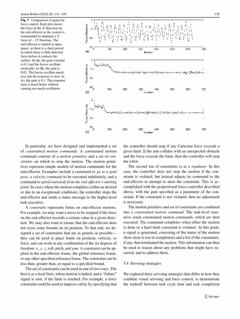
We found a simple proportional controller to be sufficient.The proportional gain (kp) is specified along with the forcecommand, since different gains are appropriate for differ-ent phases of the insertion task. As with the visual servocommands, this relative pose command is converted into adesired position in the global reference frame, then into a
desired velocity. For an example of using different gains ina static situation, see Fig. 7.
5.3 Constrained moves
We desire that the manipulator controller be usable in vari-ous scenarios. To this end, the control program should knowas little as possible about the task at hand. On the other hand,it is infeasible to have the task-level executive monitor thestatus of the manipulator in real-time at relatively high rates(e.g., 30 Hz). Instead, we prefer to provide the controllerwith a command to achieve a given pose or force, along withconstraints on the conditions under which to stop.
Auton Robot (2010) 28: 131–149 139
Fig. 7 Comparison of gains forforce control. Each plot showsthe force in the Z direction onthe end-effector as the system iscommanded to maintain a Z
force of −15 Newtons. Theend-effector is started in openspace, so there is a short periodin which there is little detectedforce before it contacts thesurface. In (a), the gain constantis 0.3 and the forces oscillateerratically. In (b), the gain is0.03. The forces oscillate muchless, but the response is slow. In(c), the gain is 0.1. The responsetime is much better withoutcausing too much oscillation
In particular, we have designed and implemented a setof constrained motion commands. A constrained motioncommand consists of a motion primitive and a set of con-straints on which to stop the motion. The motion primi-tives represent simple models of motion commands for theend-effector. Examples include a command to go to a goalpose, a velocity command to be executed indefinitely, and acommand to spiral outwards from the end-effector’s startingpoint. In cases where the motion completes (either as desiredor due to an exceptional condition), the controller stops theend-effector and sends a status message to the higher-leveltask executive.
A constraint represents limits on end-effector motions.For example, we may want a move to be stopped if the forceon the end-effector exceeds a certain value in a given direc-tion. We may also want to ensure that the end-effector doesnot cross some bounds on its position. To that end, we de-signed a set of constraints that are as generic as possible—they can be used to place limits on position, velocity, orforce, and can work in any combination of the six degrees offreedom: x, y, z, roll, pitch, and yaw. A constraint can be ap-plied in the end-effector frame, the global reference frame,or any other specified reference frame. The constraint can beless than, greater than, or equal to a specified bound.
The set of constraints can be used in one of two ways. Thefirst is as a hard limit, where motion is halted, and a “failure”signal is sent, if the limit is reached. For example, a forceconstraint could be used to improve safety by specifying that
the controller should stop if any Cartesian force exceeds agiven limit. If the arm collides with an unexpected obstacleand the force exceeds the limit, then the controller will stopthe robot.
The second use of constraints is as a regulator. In thiscase, the controller does not stop the motion if the con-straint is violated, but instead adjusts its command to theend-effector to attempt to meet the constraint. This is ac-complished with the proportional force controller describedabove, with the gain specified as a parameter of the con-straint. If the constraint is not violated, then no adjustmentis necessary.
The motion primitive and set of constraints are combinedinto a constrained motion command. The task-level exec-utive sends constrained motion commands, which are thenexecuted. The command completes when either the motionis done or a hard limit constraint is violated. At this point,a signal is generated, consisting of the status of the motion(how close it was to completion) and a list of the constraints,if any, that terminated the motion. This information can thenbe used to reason about any problems that might have oc-curred, and to address them.
5.4 Servoing strategies
We explored three servoing strategies that differ in how theycombine visual servoing and force control, to demonstratethe tradeoff between task cycle time and task completion
140 Auton Robot (2010) 28: 131–149
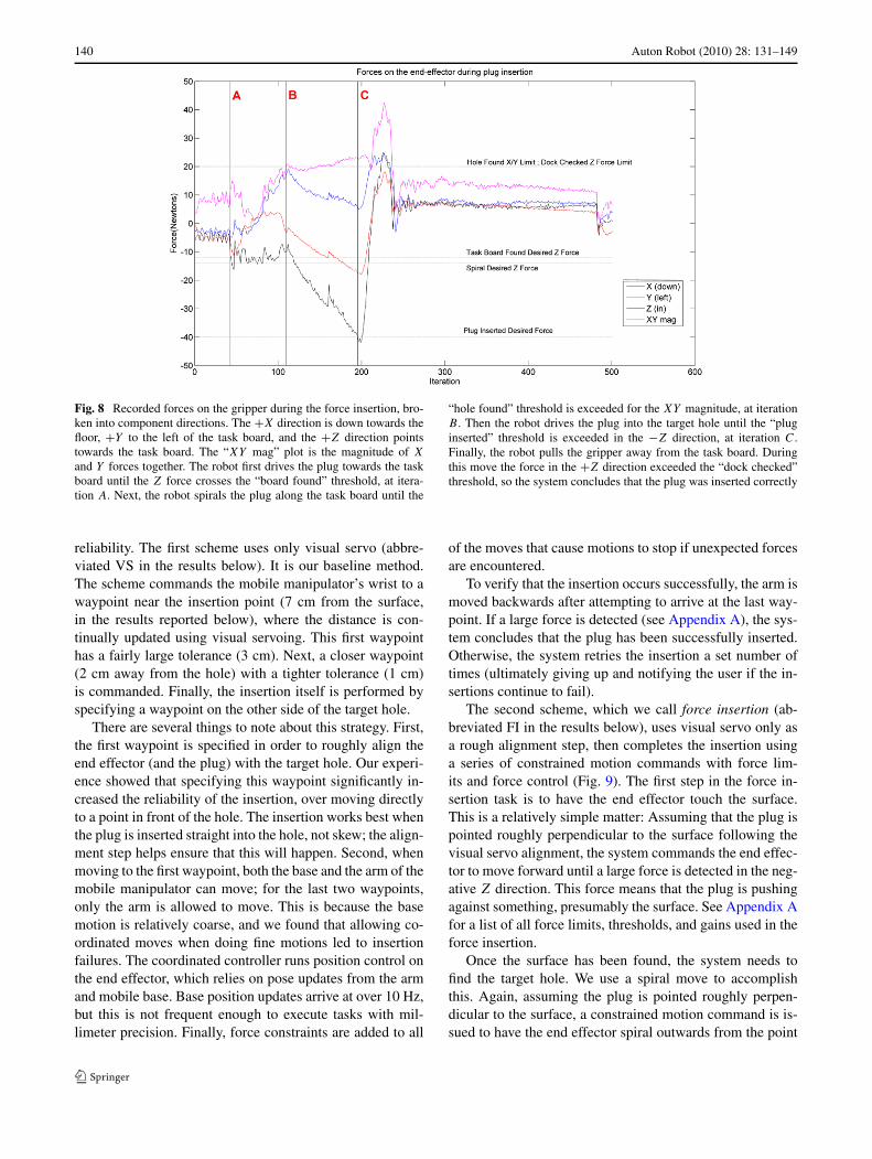
Fig. 8 Recorded forces on the gripper during the force insertion, bro-ken into component directions. The +X direction is down towards thefloor, +Y to the left of the task board, and the +Z direction pointstowards the task board. The “XY mag” plot is the magnitude of X
and Y forces together. The robot first drives the plug towards the taskboard until the Z force crosses the “board found” threshold, at itera-tion A. Next, the robot spirals the plug along the task board until the
“hole found” threshold is exceeded for the XY magnitude, at iterationB . Then the robot drives the plug into the target hole until the “pluginserted” threshold is exceeded in the −Z direction, at iteration C.Finally, the robot pulls the gripper away from the task board. Duringthis move the force in the +Z direction exceeded the “dock checked”threshold, so the system concludes that the plug was inserted correctly
reliability. The first scheme uses only visual servo (abbre-viated VS in the results below). It is our baseline method.The scheme commands the mobile manipulator’s wrist to awaypoint near the insertion point (7 cm from the surface,in the results reported below), where the distance is con-tinually updated using visual servoing. This first waypointhas a fairly large tolerance (3 cm). Next, a closer waypoint(2 cm away from the hole) with a tighter tolerance (1 cm)is commanded. Finally, the insertion itself is performed byspecifying a waypoint on the other side of the target hole.
There are several things to note about this strategy. First,the first waypoint is specified in order to roughly align theend effector (and the plug) with the target hole. Our experi-ence showed that specifying this waypoint significantly in-creased the reliability of the insertion, over moving directlyto a point in front of the hole. The insertion works best whenthe plug is inserted straight into the hole, not skew; the align-ment step helps ensure that this will happen. Second, whenmoving to the first waypoint, both the base and the arm of themobile manipulator can move; for the last two waypoints,only the arm is allowed to move. This is because the basemotion is relatively coarse, and we found that allowing co-ordinated moves when doing fine motions led to insertionfailures. The coordinated controller runs position control onthe end effector, which relies on pose updates from the armand mobile base. Base position updates arrive at over 10 Hz,but this is not frequent enough to execute tasks with mil-limeter precision. Finally, force constraints are added to all
of the moves that cause motions to stop if unexpected forcesare encountered.
To verify that the insertion occurs successfully, the arm ismoved backwards after attempting to arrive at the last way-point. If a large force is detected (see Appendix A), the sys-tem concludes that the plug has been successfully inserted.Otherwise, the system retries the insertion a set number oftimes (ultimately giving up and notifying the user if the in-sertions continue to fail).
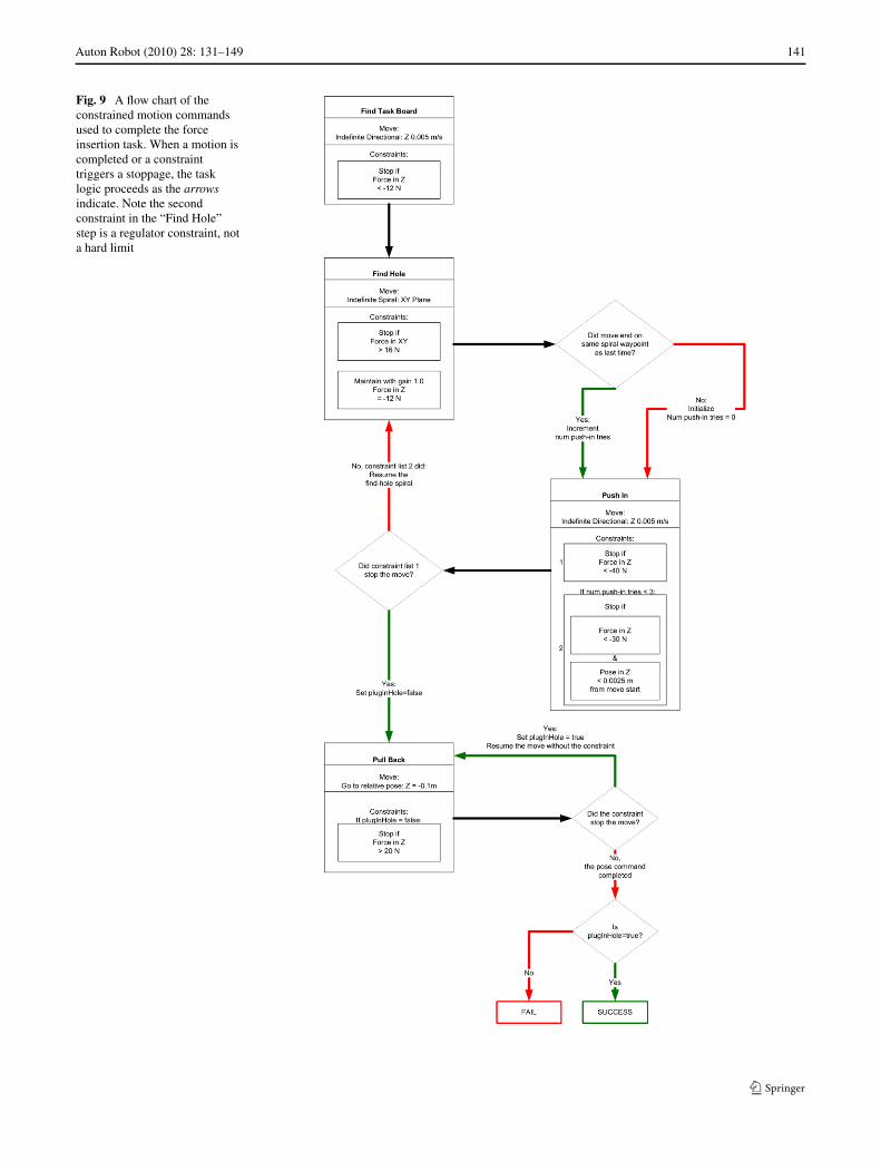
The second scheme, which we call force insertion (ab-breviated FI in the results below), uses visual servo only asa rough alignment step, then completes the insertion usinga series of constrained motion commands with force lim-its and force control (Fig. 9). The first step in the force in-sertion task is to have the end effector touch the surface.This is a relatively simple matter: Assuming that the plug ispointed roughly perpendicular to the surface following thevisual servo alignment, the system commands the end effec-tor to move forward until a large force is detected in the neg-ative Z direction. This force means that the plug is pushingagainst something, presumably the surface. See Appendix Afor a list of all force limits, thresholds, and gains used in theforce insertion.
Once the surface has been found, the system needs tofind the target hole. We use a spiral move to accomplishthis. Again, assuming the plug is pointed roughly perpen-dicular to the surface, a constrained motion command is is-sued to have the end effector spiral outwards from the point
Auton Robot (2010) 28: 131–149 141
Fig. 9 A flow chart of theconstrained motion commandsused to complete the forceinsertion task. When a motion iscompleted or a constrainttriggers a stoppage, the tasklogic proceeds as the arrowsindicate. Note the secondconstraint in the “Find Hole”step is a regulator constraint, nota hard limit
142 Auton Robot (2010) 28: 131–149
it hit the surface. The spiral is controlled in the X (down)-Y (right) plane of the end effector. A regulator constraintis provided to ensure that the plug maintains contact withthe surface by using force control in the Z direction of theend effector. When the plug crosses the target hole, the forcein Z drops because it is no longer pressing against the sur-face, and the force controller pushes the plug slightly intothe hole. With the plug caught in the hole, the spiral is nolonger maintained. A hard limit constraint is provided to en-sure that motion stops when a large force is detected in theplane of the spiral (the X and Y directions).
Once the hole is found, the system uses a constrained mo-tion command in which the end-effector is moved forward,stopping when a very large force is read, meaning the plugis fully inserted. Finally, the end-effector is commanded topull away from the surface. The same check is used as in thevisual servo scheme to check whether the plug was actuallyinserted. Figure 8 shows the forces on the end-effector as theforce insertion progresses.
The third scheme combines visual servo and force inser-tion (abbreviated VS-FI). Again, the scheme starts with avisual servo to the same rough waypoint as in the previoustwo schemes. Then the system attempts to do a visual servoas in the first scheme, with the same limitation on the forceon the end-effector. Once the visual servo has stopped, thesystem starts the force insertion. This scheme also uses theautonomous plug-docked check. The idea of this scheme isthat the visual servo could succeed by itself, so the force in-sertion may not be necessary, but for a small time cost wecould still attempt the force insertion and yield greater suc-cess.
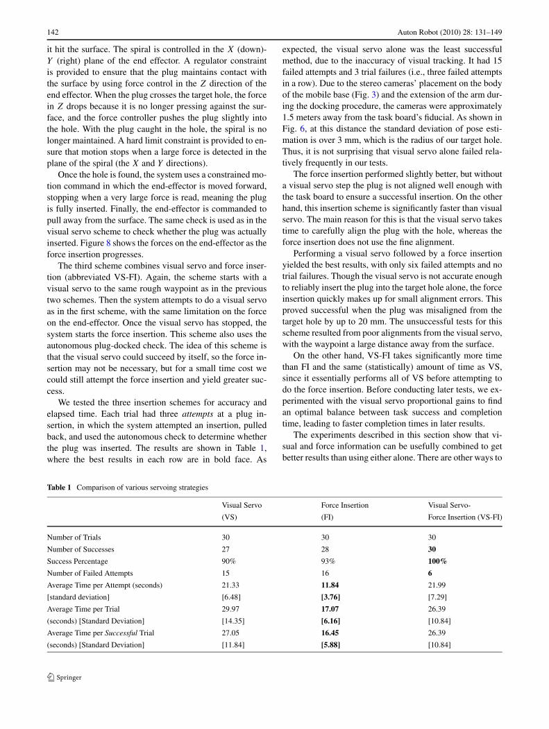
We tested the three insertion schemes for accuracy andelapsed time. Each trial had three attempts at a plug in-sertion, in which the system attempted an insertion, pulledback, and used the autonomous check to determine whetherthe plug was inserted. The results are shown in Table 1,where the best results in each row are in bold face. As
expected, the visual servo alone was the least successfulmethod, due to the inaccuracy of visual tracking. It had 15failed attempts and 3 trial failures (i.e., three failed attemptsin a row). Due to the stereo cameras’ placement on the bodyof the mobile base (Fig. 3) and the extension of the arm dur-ing the docking procedure, the cameras were approximately1.5 meters away from the task board’s fiducial. As shown inFig. 6, at this distance the standard deviation of pose esti-mation is over 3 mm, which is the radius of our target hole.Thus, it is not surprising that visual servo alone failed rela-tively frequently in our tests.
The force insertion performed slightly better, but withouta visual servo step the plug is not aligned well enough withthe task board to ensure a successful insertion. On the otherhand, this insertion scheme is significantly faster than visualservo. The main reason for this is that the visual servo takestime to carefully align the plug with the hole, whereas theforce insertion does not use the fine alignment.
Performing a visual servo followed by a force insertionyielded the best results, with only six failed attempts and notrial failures. Though the visual servo is not accurate enoughto reliably insert the plug into the target hole alone, the forceinsertion quickly makes up for small alignment errors. Thisproved successful when the plug was misaligned from thetarget hole by up to 20 mm. The unsuccessful tests for thisscheme resulted from poor alignments from the visual servo,with the waypoint a large distance away from the surface.
On the other hand, VS-FI takes significantly more timethan FI and the same (statistically) amount of time as VS,since it essentially performs all of VS before attempting todo the force insertion. Before conducting later tests, we ex-perimented with the visual servo proportional gains to findan optimal balance between task success and completiontime, leading to faster completion times in later results.
The experiments described in this section show that vi-sual and force information can be usefully combined to getbetter results than using either alone. There are other ways to
Table 1 Comparison of various servoing strategies
Visual Servo Force Insertion Visual Servo-
(VS) (FI) Force Insertion (VS-FI)
Number of Trials 30 30 30
Number of Successes 27 28 30
Success Percentage 90% 93% 100%
Number of Failed Attempts 15 16 6
Average Time per Attempt (seconds) 21.33 11.84 21.99
[standard deviation] [6.48] [3.76] [7.29]
Average Time per Trial 29.97 17.07 26.39
(seconds) [Standard Deviation] [14.35] [6.16] [10.84]
Average Time per Successful Trial 27.05 16.45 26.39
(seconds) [Standard Deviation] [11.84] [5.88] [10.84]
Auton Robot (2010) 28: 131–149 143
combine visual and force feedback, though. For example, acontrol scheme could simultaneously use visual informationto servo left/right and up/down with respect to the target holewhile using force information to maintain contact with thetask board and insert the plug. It is our intention to explorealternate combinations in future work.
6 Task-level control
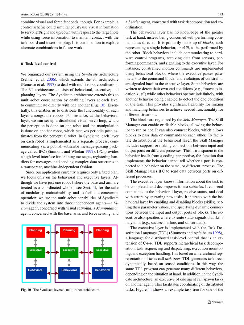
We organized our system using the Syndicate architecture(Sellner et al. 2006), which extends the 3T architecture(Bonasso et al. 1997) to deal with multi-robot coordination.The 3T architecture consists of behavioral, executive, andplanning layers. The Syndicate architecture extends this tomulti-robot coordination by enabling layers at each levelto communicate directly with one another (Fig. 10). Essen-tially, this enables us to distribute the functionality of eachlayer amongst the robots. For instance, at the behaviorallayer, we can set up a distributed visual servo loop, wherethe perception is done on one robot and the manipulationis done on another robot, which receives periodic pose es-timates from the perceptual robot. In Syndicate, each layeron each robot is implemented as a separate process, com-municating via a publish-subscribe message-passing pack-age called IPC (Simmons and Whelan 1997). IPC providesa high-level interface for defining messages, registering han-dlers for messages, and sending complex data structures ina transparent, machine-independent fashion.
Since our application currently requires only a fixed plan,we focus only on the behavioral and executive layers. Al-though we have just one robot (where the base and arm aretreated as a coordinated whole—see Sect. 4), for the sakeof modularity, maintainability, and to facilitate concurrentoperation, we use the multi-robot capabilities of Syndicateto divide the system into three independent agents—a Vi-sion agent, concerned with visual servoing, a Manipulationagent, concerned with the base, arm, and force sensing, and
Fig. 10 The Syndicate layered, multi-robot architecture
a Leader agent, concerned with task decomposition and co-ordination.
The behavioral layer has no knowledge of the greatertask at hand, instead being concerned with performing com-mands as directed. It is primarily made up of blocks, eachrepresenting a single behavior, or skill, to be performed bythe robot. Block behaviors include communicating to hard-ware control programs, receiving data from sensors, per-forming commands, and signaling to the executive layer. Forinstance, constrained motion commands are implementedusing behavioral blocks, where the executive passes para-meters to the command block, and violations of constraintsare signaled back to the executive layer. Some behaviors arewritten to detect their own end conditions (e.g., “move to lo-cation x, y”) while other behaviors operate indefinitely, withanother behavior being enabled to detect the end conditionof the task. This provides significant flexibility for mixingand matching behaviors to achieve needed functionality fordifferent situations.
The blocks are organized by the Skill Manager. The SkillManager can enable or disable blocks, allowing the behav-ior to run or not. It can also connect blocks, which allowsblocks to pass data or commands to each other. To facili-tate distribution at the behavioral layer, the Skill Managerincludes support for making connections between input andoutput ports on different processes. This is transparent to thebehavior itself: from a coding perspective, the function thatimplements the behavior cannot tell whether a port is con-nected to a behavior on the same, or different, process. TheSkill Manager uses IPC to send data between ports on dif-ferent processes.
The executive layer knows information about the task tobe completed, and decomposes it into subtasks. It can sendcommands to the behavioral layer, receive status, and dealwith errors by spawning new tasks. It interacts with the be-havioral layer by enabling and disabling blocks (skills), set-ting their parameter values, and specifying dynamic connec-tions between the input and output ports of blocks. The ex-ecutive also specifies where to route status signals that skillsmay emit (e.g., success, failure, and sensor data).
The executive layer is implemented with the Task De-scription Language (TDL) (Simmons and Apfelbaum 1998),a language for distributed task-level control that is an ex-tension of C++. TDL supports hierarchical task decompo-sition, task sequencing and dispatching, execution monitor-ing, and exception handling. It is based on a hierarchical rep-resentation of tasks call task trees. TDL generates task treesdynamically, based on sensed conditions. In this way, thesame TDL program can generate many different behaviors,depending on the situation at hand. In addition, in the Syndi-cate architecture, an executive of one agent can spawn taskson another agent. This facilitates coordinating of distributedtasks. Figure 11 shows an example task tree for one of the
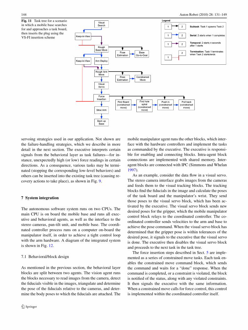
144 Auton Robot (2010) 28: 131–149
Fig. 11 Task tree for a scenarioin which a mobile base searchesfor and approaches a task board,then inserts the plug using theVS-FI insertion scheme
servoing strategies used in our application. Not shown arethe failure-handling strategies, which we describe in moredetail in the next section. The executive interprets certainsignals from the behavioral layer as task failures—for in-stance, unexpectedly high (or low) force readings in certaindirections. As a consequence, various tasks may be termi-nated (stopping the corresponding low-level behaviors) andothers can be inserted into the existing task tree (causing re-covery actions to take place), as shown in Fig. 9.
7 System integration
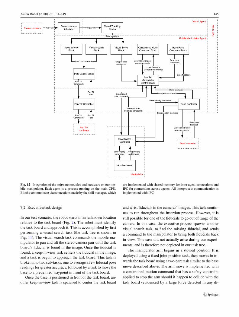
The autonomous software system runs on two CPUs. Themain CPU is on board the mobile base and runs all exec-utive and behavioral agents, as well as the interface to thestereo cameras, pan-tilt unit, and mobile base. The coordi-nated controller process runs on a computer on-board themanipulator itself, in order to achieve a tight control loopwith the arm hardware. A diagram of the integrated systemis shown in Fig. 12.
7.1 Behavioral/block design
As mentioned in the previous section, the behavioral layerblocks are split between two agents. The vision agent runsthe blocks necessary to read images from the camera, detectthe fiducials visible in the images, triangulate and determinethe pose of the fiducials relative to the cameras, and deter-mine the body poses to which the fiducials are attached. The
mobile manipulator agent runs the other blocks, which inter-face with the hardware controllers and implement the tasksas commanded by the executive. The executive is responsi-ble for enabling and connecting blocks. Intra-agent blockconnections are implemented with shared memory. Inter-agent blocks are connected with IPC (Simmons and Whelan1997).
As an example, consider the data flow in a visual servo.The stereo camera interface grabs images from the camerasand feeds them to the visual tracking blocks. The trackingblocks find the fiducials in the image and calculate the posesof the task board and the manipulator’s wrist. They sendthose poses to the visual servo block, which has been ac-tivated by the executive. The visual servo block sends newdesired poses for the gripper, which the mobile manipulatorcontrol block relays to the coordinated controller. The co-ordinated controller sends velocities to the arm and base toachieve the pose command. When the visual servo block hasdetermined that the gripper pose is within tolerances of thedesired pose, it signals to the executive that the visual servois done. The executive then disables the visual servo blockand proceeds to the next task in the task tree.
The force insertion steps described in Sect. 5 are imple-mented as a series of constrained move tasks. Each task en-ables the constrained move command block, which sendsthe command and waits for a “done” response. When thecommand is completed, or a constraint is violated, the blockis notified of the status, along with any violated constraints.It then signals the executive with the same information.When a constrained move calls for force control, this controlis implemented within the coordinated controller itself.
Auton Robot (2010) 28: 131–149 145
Fig. 12 Integration of the software modules and hardware on our mo-bile manipulator. Each agent is a process running on the main CPU.Blocks communicate via connections made by the skill manager, which
are implemented with shared memory for intra-agent connections andIPC for connections across agents. All interprocess communication isimplemented with IPC
7.2 Executive/task design
In our test scenario, the robot starts in an unknown locationrelative to the task board (Fig. 2). The robot must identifythe task board and approach it. This is accomplished by firstperforming a visual search task (the task tree is shown inFig. 11). The visual search task commands the mobile ma-nipulator to pan and tilt the stereo camera pair until the taskboard’s fiducial is found in the image. Once the fiducial isfound, a keep-in-view task centers the fiducial in the image,and a task is begun to approach the task board. This task isbroken into two sub-tasks: one to average a few fiducial posereadings for greater accuracy, followed by a task to move thebase to a predefined waypoint in front of the task board.
Once the base is positioned in front of the task board, an-other keep-in-view task is spawned to center the task board
and wrist fiducials in the cameras’ images. This task contin-ues to run throughout the insertion process. However, it isstill possible for one of the fiducials to go out of range of thecamera. In this case, the executive process spawns anothervisual search task, to find the missing fiducial, and sendsa command to the manipulator to bring both fiducials backin view. This case did not actually arise during our experi-ments, and is therefore not depicted in our task tree.
The manipulator arm begins in a stowed position. It isdeployed using a fixed joint position task, then moves in to-wards the task board using a two-part task similar to the basemove described above. The arm move is implemented witha constrained motion command that has a safety constraintapplied to stop the arm should it happen to collide with thetask board (evidenced by a large force detected in any di-
146 Auton Robot (2010) 28: 131–149
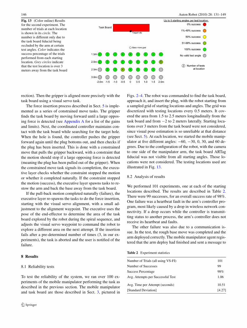
Fig. 13 (Color online) Resultsfor the second experiment. Thenumber of trials at each locationis shown in its circle. Thenumber is different only due tothe task board fiducial beingoccluded by the arm at certaintest angles. Color indicates thesuccess percentage of the trialsperformed from each startinglocation. Grey circles indicatethat the test location is over 3meters away from the task board
rection). Then the gripper is aligned more precisely with thetask board using a visual servo task.
The force insertion process described in Sect. 5 is imple-mented as a series of constrained move tasks. The gripperfinds the task board by moving forward until a large oppos-ing force is detected (see Appendix A for a list of the gainsand limits). Next, the coordinated controller maintains con-tact with the task board while searching for the target hole.When the hole is found, the controller pushes the gripperforward again until the plug bottoms out, and then checks ifthe plug has been inserted. This is done with a constrainedmove that pulls the gripper backward, with a constraint thatthe motion should stop if a large opposing force is detected(meaning the plug has been pulled out of the gripper). Whenthe constrained move task signals its completion, the execu-tive layer checks whether the constraint stopped the motionor whether it completed naturally. If the constraint stoppedthe motion (success), the executive layer spawns tasks to re-stow the arm and back the base away from the task board.
If the pull-back motion completed naturally (failure), theexecutive layer re-spawns the tasks to do the force insertion,starting with the visual servo alignment, with a small ad-justment to the alignment waypoint. The executive uses thepose of the end-effector to determine the area of the taskboard explored by the robot during the spiral sequence, andadjusts the visual servo waypoint to command the robot toexplore a different area on the next attempt. If the insertionfails after a pre-determined number of times (3, in our ex-periments), the task is aborted and the user is notified of thefailure.
8 Results
8.1 Reliability tests
To test the reliability of the system, we ran over 100 ex-periments of the mobile manipulator performing the task asdescribed in the previous section. The mobile manipulatorand task board are those described in Sect. 3, pictured in
Figs. 2–4. The robot was commanded to find the task board,approach it, and insert the plug, with the robot starting froma sampled grid of starting locations and angles. The grid wasdiscretized with testing locations every 0.5 meters. It cov-ered the area from 1.5 to 2.5 meters longitudinally from thetask board and from −2 to 2 meters laterally. Starting loca-tions over 3 meters from the task board were not considered,since visual pose estimation is so unreliable at that distance(see Sect. 5). At each location, we started the mobile manip-ulator at five different angles: −60, −30, 0, 30, and 60 de-grees. Due to the configuration of the robot, with the camerato one side of the manipulator arm, the task board ARTagfiducial was not visible from all starting angles. Those lo-cations were not considered. The testing locations used areillustrated in Fig. 13.
8.2 Analysis of results
We performed 101 experiments, one at each of the startinglocations described. The results are described in Table 2.There were 99 successes, for an overall success rate of 98%.One failure was a heartbeat fault in the arm’s controller pro-gram, most likely caused by a drop in wireless network con-nectivity. If a drop occurs while the controller is transmit-ting status to another process, the arm’s controller does notreceive its heartbeat and faults.
The other failure was also due to a communication is-sue. In the test, the rough base move was completed and thearm deployed correctly. The mobile manipulator agent regis-tered that the arm deploy had finished and sent a message to
Table 2 Experiment statistics
Number of Trials (all using VS-FI) 101
Number of Successes 99
Success Percentage 98%
Avg. Attempts per Successful Test 1.06
Avg. Time per Attempt (seconds) 10.51
[Standard Deviation] [4.27]
Auton Robot (2010) 28: 131–149 147
the leader agent. However, the leader agent never receivedthe message. We have never previously seen this error inany of our experience with using the three-layer architectureand the IPC communication system, and do not even knowwhether to attribute it to a hardware or software issue.
During the 101 experiments, there were four instancesof a missed attempt, in which a force reading triggered thelow-level controller to complete its motion despite the plugnot being inserted correctly. In each case, the system recov-ered with a completed insertion on the next attempt, whichdemonstrates the flexibility of the task control system. Theexecutive layer detected the failed insertion attempt, ad-justed the waypoints to search for the target hole in a slightlydifferent location, and re-spawned the tasks to attempt theinsertion again. In each case the second insertion attemptwas successful. Note that the time reported starts when therough base move has finished and the arm is deployed. Notealso that the average time is twice as fast as in the earliertests (Table 1), which is mainly due to finding visual servoproportional gains that strike an optimal balance betweentask success and completion time.
9 Conclusions
Robotic assembly requires a system with high flexibility andthe capability to deal with inherent uncertainties and excep-tions. A robust mobile manipulation system is one of many
new and promising technologies that could address thesechallenges. In this paper, we have presented an autonomousmobile manipulator that can effectively overcome uncer-tainties and exceptions by using three key technologies—coordinated base and manipulator control, combined visualand force servoing, and error recovery through flexible task-level control. In particular, with constrained motion primi-tives that can detect constraint violation conditions, reactivetask control can be used to significantly increase overall sys-tem robustness. This mobile manipulation system has beendemonstrated experimentally to achieve high system robust-ness and reliability for a “peg-in-a-hole” task that is com-monly encountered in automotive wiring harness assembly.
In the future, we intend to extend our work to deal witha moving target—that is, having the task board move, as ifon an assembly line, and having the mobile manipulator fol-low the task board and doing the insertion on the move. Weanticipate that, while details of the task approach will differfrom the static case, the technologies reported in this paperwill be able to handle this, and similar, more complex sce-narios in the realm of autonomous assembly.
If, and when, a robust, reliable and capable autonomousrobotic assembly system is achieved, the approach for ro-botic assembly will be fundamentally advanced, resulting ina much more reactive, adaptable, and intelligent system thatrequires minimal human intervention and removes the re-quirement of precisely known and rigid structure from themanufacturing and assembly environments.
Appendix A: Gains and thresholds used in the docking experiments
Gain/Threshold Value Dimension Method of Determining
Visual Servo Proportional Gain 0.7 XYZ relative towaypoint
Trial and error to maximize success andtime of completion
Visual Servo Waypoint DistanceTolerance
3 cm total (XYZ) XYZ relative towaypoint
Trial and error to maximize success andtime of completion
Visual Servo Waypoint AngularTolerance
5 degrees in eachdirection
Roll, Pitch, Yaw relativeto waypoint
Trial and error to maximize success andtime of completion
Touch Board Force Threshold −12 Newtons Z relative to gripper Analyzed data of experiments drivinggripper towards task board
Maintain Contact with Board ForceTarget
−14 Newtons Z relative to gripper Trial and error to maintain contact withtask board
Maintain Contact with BoardProportional Gain
0.0015meters/Newtons
Z relative to gripper Trial and error to maintain contact
Find Hole Force Threshold +20 Newtons XY relative to gripper Data analysis of experiments sliding plugalong task board freely vs. catching targethole
Stop Inserting Plug Force Threshold −40 Newtons Z relative to gripper Data analysis of experiments pushingplug in until fully inserted
Plug Inserted Check Force Threshold +20 Newtons Z relative to gripper Data analysis of experiments pulling backuninserted plug vs. inserted plug
148 Auton Robot (2010) 28: 131–149
References
Bar-Itzhack, Y. (2000). New method for extracting the quaternion froma rotation matrix. AIAA Journal of Guidance, Control, and Dy-namics, 23(6), 1085–1087.
Bischoff, R. (1997). HERMES—a humanoid manipulator for servicetasks. In Proceedings of the international conference on field andservice robotics, Canberra, December, 1997.
Bonasso, R. P., Firby, R. J., Gat, E., Kortenkamp, D., Miller, D. P., &Slack, M. G. (1997). Experiences with an architecture for intel-ligent, reactive agents. Journal of Experimental and TheoreticalArtificial Intelligence, 9(1).
Brock, O., & Khatib, O. (2002). Elastic strips: a framework for motiongeneration in human environments. The International Journal ofRobotics Research, 21(12), 1031–1052.
Chiaverini, S. (1997). Singularity-robust task-priority redundancy res-olution for real-time kinematic control of robot manipulators.IEEE Transactions on Robotics and Automation, 13, 398–410.
De Schutter, J., De Laet, T., Rutgeerts, J., Decré, W., Smits, R., Aer-beliën, E., Claes, K., & Bruyninckx, H. (2007). Constraint-basedtask specification and estimation for sensor-based robot systemsin the presence of geometric uncertainty. International Journal ofRobotics Research, 26(5), 433–455.
Dillman, R., Ehrenmann, M., Steinhaus, P., Rogalla, O., & Zollner, R.(2002). Human friendly programming of humanoid robots—theGerman collaborative research center. In Proceedings of the IEEEinternational workshop of robot and human interactive communi-cation.
Donald, B. R. (1990). Planning multi-step error detection and recoverystrategies. The International Journal of Robotics Research, 892–897.
Duchaine, V., & Gosselin, C. (2007). General model of human-robotcooperation using a novel velocity based variable impedance con-trol. In Proceedings of the second joint EuroHaptics conferenceand symposium on haptic interfaces for virtual environment andteleoperator systems.
Edsinger, A., & Kemp, C. (2006). Manipulation in human environ-ments. In Proceedings of the IEEE/RSJ international conferenceon humanoid robotics.
Fiala, M. (2005). ARTag, a fiducial marker system using digital tech-niques. IEEE Computer Vision and Pattern Recognition, 2, 590–596.
Holmberg, R., & Khatib, O. (2000). Development and control of aholonomic mobile robot for mobile manipulation tasks. The In-ternational Journal of Robotics Research, 19(11), 1066–1074.
Kim, J., Chung, W. K., Youm, Y., & Lee, B. H. (2002). Real-time ZMPcompensation method using null motion for mobile manipulators.In Proceedings of the IEEE international conference on roboticsand automation, Washington DC.
Kragic, D., Crinier, S., Brunn, D., & Christensen, H. I. (2003). Vi-sion and tactile sensing for real world tasks. In Proceedings ofthe IEEE international conference on robotics and automation,Taipei, Taiwan.
Mason, M. (1979). Compliance and force control for computercontrolled manipulators. MIT Artificial Intelligence LaboratoryMemo 515, April 1979.
Mills, J., & Goldenberg, A. (1989). Force and position control of ma-nipulators during constrained motion tasks. IEEE Transactions onRobotics and Automation, 5(1), 30–46.
Nakamura, Y., & Hanafusa, H. (1986). Inverse kinematic solutionswith singularity robustness for robot manipulator control. Journalof Dynamic Systems, Measurement, and Control, 108, 163–171.
Peshkin, M. A., Colgate, J. E., Akella, P., & Wannasuphoprasit, W.(2000). Cobots in materials handling, In M. Cutkosky, R. Howe,K. Salisbury & M. Srinivasan (Eds.), Human and Machine Hap-tics. Cambridge: MIT Press.
Petersson, L., Jensfelt, P., Tell, D., Strandberg, M., Kragic, D., & Chris-tensen, H. I. (2002). Systems integration for real-world manipu-lation tasks. In Proceedings of the IEEE international conferenceon robots and automation.
Raibert, M. H., & Craig, J. J. (1981). Hybrid position/force control ofmanipulators. Transactions of ASME, Journal DSMC, 103, 126–133.
Sciavicco, L., & Siciliano, B. (2005). Modeling and control of robotmanipulators (2nd ed.). London: Springer.
Schaal, S. (2007). The New Robotics—towards human-centered ma-chines. HFSP Journal, 1(2), 115–126.
Se, S., Lowe, D., & Little, J. (2005). Vision-based global localizationand mapping for mobile robots. IEEE Transactions on Robotics,21(3), 364–375.
Sellner, B., Heger, F. W., Hiatt, L. M., Simmons, R., & Singh, S.(2006). Coordinated multi-agent teams and sliding autonomy forlarge-scale assembly. Proceedings of the IEEE, Special Issue onMulti-Agent Systems, 94(7), 1425–1444.
Shin, D., Hamner, B., Singh, S., & Hwangbo, M. (2003). Motion plan-ning for a mobile manipulator with imprecise locomotion. In Pro-ceedings of IEEE/RSJ international conference on intelligent ro-bots and systems (pp. 847–853).
Simmons, R., & Whelan, G. (1997). Visualization tools for validat-ing software of autonomous spacecraft. In Proceedings of interna-tional symposium on artificial intelligence, robotics and automa-tion in space, Tokyo, Japan, July 1997.
Simmons, R., & Apfelbaum, D. (1998). A task description language forrobot control. In Proceedings of conference on intelligent roboticsand systems, Vancouver, Canada, October 1998.
Wampler, C. W. (1986). Manipulator inverse kinematic solutions basedon vector formulations and damped least-squares methods. IEEETransactions on Systems, Man, and Cybernetics, SMC-16, 93–101.
Whitney, D. E. (1969). Resolved motion rate control of manipulatorsand human prostheses. IEEE Transactions on Man-Machine Sys-tem, MMS-IO, 47–53.
Yamamoto, Y., & Yun, X. (1992). Coordinating locomotion and manip-ulation of a mobile manipulator. In Proceedings of the 31st IEEEconference on decision and control (Vol. 3, pp. 2643–2648), Tuc-son, AZ, USA.
Yoshikawa, T. (1987). Dynamic hybrid position/force control of robotmanipulators—description of hand constraints and calculation ofjoint driving force. IEEE Journal of Robotics and Automation,RA-3(5), 386–392.
Yuan, J. S. (1988). Closed-loop manipulator control using quaternionfeedback. IEEE Journal of Robotics and Automation, 4(4), 434–440.
Brad Hamner received a B.S. inmathematics from Carnegie Mel-lon University in 2002 and an M.S.in robotics from Carnegie MellonUniversity in 2006. He currentlyworks in the Robotics Institute onautonomous ground and air vehi-cles.
Auton Robot (2010) 28: 131–149 149
Seth Koterba has worked with andstudied robotics at Carnegie Mel-lon University since 2003. His cur-rent research focuses primarily onmobile manipulation, in particular,coordinated control of high degreeof freedom manipulators and mo-bile bases. A central element of hisresearch is on understanding howto utilize the redundant degrees offreedom in high DOF systems tobeneficially reconfigure without im-pacting end effector placement.
Jane Shi is a staff researcher at theManufacturing Systems ResearchLab, General Motor R&D Centerof Warren, Michigan. Her currentresearch focuses on addressing thefundamental challenges in achiev-ing a robust, intelligent, and capa-ble autonomous mobile robotic sys-tem for automotive assembly tasks.Dr. Shi is a recipient of the GM BossKettering Innovation Award (2006)and the GM R&D Charles L. Mc-Cuen Special Achievement Award(2006) and is a member of the IEEEand Robotics and Automation (RA)Society.
Reid Simmons is a Research Pro-fessor in the School of ComputerScience at Carnegie Mellon Uni-versity. He earned his B.A. degreein 1979 in Computer Science fromSUNY at Buffalo, and his M.S. andPh.D. degrees from MIT in 1983and 1988, respectively, in the fieldof Artificial Intelligence. His the-sis work focused on the combina-tion of associational and causal rea-soning for planning and interpreta-tion tasks. The research analyzedthe relationships between differentaspects of expertise and developed
a domain-independent theory of debugging faulty plans. Since com-ing to Carnegie Mellon in 1988, Dr. Simmons’ research has focusedon developing self-reliant robots that can autonomously operate overextended periods of time in unknown, unstructured environments. Thiswork involves issues of robot control architectures that combine delib-erative and reactive control,probabilistic planning and reasoning, mon-itoring and fault detection, and robust indoor and outdoor navigation.More recently, Dr. Simmons has focused on the areas of coordinationof multiple heterogeneous robots, robotic assembly, and human-robotsocial interaction. Over the years, he has been involved in the develop-ment of over a dozen autonomous robots.
Sanjiv Singh received a Ph.D. in ro-botics from Carnegie Mellon Uni-versity in 1995, an M.S. in robot-ics from Carnegie Mellon in 1992,and an M.S. in electrical engineer-ing from Lehigh University in 1985.He is currently an Associate Re-search Professor at the Robotics In-stitute at Carnegie Mellon and aneditor of the Journal of Field Robot-ics.