an apropos kinematic framework for the numerical modeling...
TRANSCRIPT

Computers and Structures 117 (2013) 48–57
Contents lists available at SciVerse ScienceDirect
Computers and Structures
journal homepage: www.elsevier .com/locate/compstruc
An apropos kinematic framework for the numerical modeling of frictionstir welding
0045-7949/$ - see front matter � 2012 Elsevier Ltd. All rights reserved.http://dx.doi.org/10.1016/j.compstruc.2012.12.006
⇑ Corresponding author. Tel.: +34 93 401 6529; fax: +34 93 401 6517.E-mail addresses: [email protected] (N. Dialami), [email protected]
(M. Chiumenti), [email protected] (M. Cervera), [email protected](C.A. de Saracibar).
Narges Dialami ⇑, Michele Chiumenti, Miguel Cervera, Carlos Agelet de SaracibarInternational Center for Numerical Methods in Engineering (CIMNE), Technical University of Catalonia, Module C1, North Campus, C/ Gran Capitán s/n, 08034 Barcelona, Spain
a r t i c l e i n f o
Article history:Received 1 August 2012Accepted 4 December 2012
Keywords:Friction stir weldingApropos kinematic frameworkParticle tracingVisco-plasticityFrictionStabilized finite element method
a b s t r a c t
This paper describes features of a fully coupled thermo-mechanical model for Friction Stir Welding (FSW)simulation. An apropos kinematic setting for different zones of the computational domain is introducedand an efficient coupling strategy is proposed. Heat generation via viscous dissipation as well as frictionalheating is considered.
The results of the simulation using the proposed model are compared with the experimental evidence.The effect of slip and stick condition on non-circular pin shapes is analyzed. Simulation of material stir-ring is also carried out via particle tracing, providing insight of the material flow pattern in the vicinity ofthe pin.
� 2012 Elsevier Ltd. All rights reserved.
1. Introduction are produced. All these benefits render FSW appropriate for differ-
1.1. The industrial process
FSW is a solid state joining technology in which no gross melt-ing of the welded material takes place. It is a relatively new tech-nique (developed by The Welding Institute (TWI), in Cambridge,UK, in 1991) widely used over the past decades for joining alumi-num alloys. Recently, FSW has been applied to the joining of a widevariety of other metals and alloys such as magnesium, titanium,steel and others. This process offers a number of advantages overconventional joining processes (such as e.g. fusion welding). Themain advantages include: (a) absence of the need for expensiveconsumables; (b) ease of automation of the machinery involved;(c) low distortion of the work-piece; and (d) good mechanicalproperties of the resultant joint [1]. Additionally being a solid statetechnique, it avoids all the problems associated to the cooling fromthe liquid phase. Issues such as porosity, solute redistribution,solidification cracking and liquation cracking are not encounteredduring FSW. In general, FSW is found to produce a low concentra-tion of defects and is very tolerant to variations in process param-eters and materials. Furthermore, since welding occurs by thedeformation of material at temperatures below the melting tem-perature, many problems commonly associated with joining of dis-similar aluminum alloys can be avoided, thus high-quality welds
ent industrial applications where metallurgical characteristicsshould be retained, such as in aeronautic, naval and automotiveindustry.
In FSW, a pin rotating at a constant speed is inserted into thewelding line between two pieces of sheet or plate material (whichare butted together) generating heat. This heat is produced by thefriction between the pin shoulder and the work-pieces and by themechanical mixing (stirring) in the solid state. The plasticizedmaterial is stirred by the pin and the heated material is forced toflow around the pin to its backside. There the material is consoli-dated to create a weld as the pin advances. As the temperaturecools down, a solid continuous joint between the two platesemerges. Fig. 1 shows the process schematically: The work-piecesjoined by the weld are located on either the retreating or advanc-ing side of the weld. The retreating side is the one where the pinrotating direction is opposite to the pin travel direction and paral-lel to the metal flow direction. In contrast, the advancing side is theone where the pin rotation direction is the same as the pin traveldirection and opposite to the metal flow direction.
The numerical simulation is an important tool for understand-ing the mechanisms of the FSW process. It enables obtaining bothqualitative and quantitative insights of the welding characteristicswithout performing costly experiments. Flexibility of the numeri-cal methods (in particular FEM) in treating complex geometriesand boundary conditions defines an important advantage of thesemethods against their analytical counterparts.
The FSW simulation typically involves studies of the transienttemperature and its dependence on the rotation and advancingspeed, residual stresses in the work-piece, etc. This simulation is

Fig. 1. Friction stir welding schematic [2].
N. Dialami et al. / Computers and Structures 117 (2013) 48–57 49
not an easy task since it involves the interaction of thermal,mechanical and metallurgical phenomena. Up to now severalresearchers have carried out computational modeling of FSW. Inthe majority of the works, FSW process is studied at a global level.Simulation carried out at global level investigates the effect ofmoving heat source on the entire structure to be welded while localphenomena such as material flow are excluded. In a global ap-proach, the generated heat is considered an input parameter. Indifferent global studies various heat source types ranging frompoint sources to the distributed ones are considered. These studiestypically analyze the effect of welding process on the structuralbehavior in terms of distortions, residual stresses or weaknessalong the welding line, among others.
Askari et al. [3] use the CTH finite volume hydrocode coupled toan advection–diffusion solver for the energy balance equation. Par-ticular attention is given to the residual stresses in FSW joints in[4–6]. Giorgi et al. [5] study the effect of different shoulder geom-etries on the longitudinal stress distribution. Additionally, Dattomaet al. [6] investigate the influence of shoulder geometry on heatgeneration during the welding process. Chen and Kovacevic [7]use the commercial FEM software ANSYS for a Lagrangian finiteelement model of aluminum alloy AA-6061-T6. The welding pinis modeled as a heat source. This simple model severely limitsthe accuracy in the predicted stress and force, as the strain ratedependence is not included in the material model. However, theauthors are able to investigate the effect of the heat moving sourceon the work-piece material.
Since the temperature is crucial for the FSW simulation, theheat source needs to be well-modeled. This consideration obligesto study the process at the local level where the simulation is con-centrated on the stirring zone. For this type of simulation, the heatpower is assumed to be generated either by the visco-plastic dissi-pation or by the friction at the contact interface. At this level themajority of the process phenomena can be analyzed: the relation-ship between rotation and advancing speed, the contact mecha-nisms, the effect of pin shape, the material flow within the heataffected zone (HAZ), the size of the HAZ and the correspondingconsequences on the microstructure evolution, etc.
Among the local level studies, Cho et al. [8] use an Eulerian ap-proach including thermo-mechanical models without consideringthe transient temperature in simulation. The strain hardeningand texture evolution in the friction stir welds of stainless steelis studied in this paper. A Lagrangian approach with intensive re-meshing is employed in [9] while similar approaches are appliedin [10,11] which are not numerically efficient. Nandan et al.[12,13] employ a control volume approach for discretization ofthe FSW domain. The material is considered as 3D visco-plastic
flow to show the nature of mass transportation in FSW. Assidiet al. [14] and Guerdoux [16] use an ALE formulation implementedinto the commercial software with a splitting approach (oneLagrangian step followed by an advection phase), remapping tech-niques and an adaptive re-meshing scheme based on error estima-tion. Buffa et al. [15] predict the residual stresses in a 3D FE modelfor the FSW simulation of butt joints through a single block ap-proach. The model is able to predict the residual stresses by consid-ering only thermal actions.
Despite the wide range of FSW application in industry and re-lated extensive research, many aspects of the process and of theensuing mechanical properties are still not well-understood andrequire further studies. These include material mixing in the vicin-ity of the pin, influence of the pin shape and non-linear materialbehavior. The effort aimed at understanding the FSW process, suchas computational modeling and simulation, is limited mainly be-cause of the complexity of this thermo-mechanical process (e.g.material flow, temperature rise, large plastic deformation, contactand friction). Most of the existing models have limitations in eitherthe representation of the non-circular pin geometries, or the non-linear material behavior, or application of the boundary conditions,or involve costly re-meshing procedure.
In this work we strive to develop a numerical tool for studyingFSW at local level. The objective, however, is not to compromise onthe computational efficiency and to develop a robust and efficientapproach. One of the main objectives of the present work is toestablish an apropos kinematic framework for the FSW simulationwith arbitrary pin shapes together with an accurate definition ofthe boundary conditions. This framework allows to avoid reme-shing and remapping of the state variables. Section 2 is explainingthe division of the geometry into sub-domains and introduces anappropriate kinematic framework for each one of them. Couplingbetween each domain is detailed including the friction contact.As the heat due to plastic dissipation in FSW is usually large andcannot be neglected, mechanical and thermal equations becomecoupled thus necessitating a fully coupled thermo-mechanicalmodel. Section 3 is devoted to the presentation of the coupled gov-erning equations together with a rigid visco-plastic model suitablefor the simulation of high deformation rate in FSW. Section 4 is de-voted to particle tracing method applied for the visualization ofmaterial stirring around the pin. Section 5 is validating the workby simulation of some benchmarks and comparing them withexperimental evidence.
2. Apropos kinematic framework
In modeling FSW, the choice of kinematic frameworks for differ-ent domain zones (regions) crucially impacts the computationalefficiency and the solution quality. For defining the suitable frame-works several observations must be made:
� The extent of the material deformation varies in differentregions of the analysis domain.� Pins used in practice are not necessarily circular.� Boundary conditions must be applied conveniently.� Re-definition of the integration domain and re-meshing is pref-
erably to be avoided.
Considering these, the domain of the analysis is divided intothree parts which are the Pin, the Plates and the heat affected zone(HAZ), associating a specific kinematic framework to each one ofthem.
Pin: The pin (Fig. 2a) undergoes exclusively a rigid-body rota-tion at a constant speed and its deformation is not considered in

Fig. 2. Kinematic zones (a) Pin (b) HAZ (c) Plate.
50 N. Dialami et al. / Computers and Structures 117 (2013) 48–57
the analysis. Thus, a Lagrangian framework is a natural choice forthe description of the pin’s movement.
HAZ: HAZ is a part of work-piece close to the pin where most ofthe material deformation takes place. The extent of the deforma-tion in the vicinity of the pin is such, that it cannot be efficientlyhandled with a classical updated Lagrangian scheme, since itwould lead to the mesh degradation and therefore necessity of acontinuous re-meshing. At the same time, use of an Eulerian for-mulation would not be straight-forward for any pin shapes otherthan circular1. In the case of non-circular pins, additional techniquesfor tracking the moving boundary would be necessary as well asredefinition of the integration domain at every time step.
The ALE formulation allows overcoming the above mentionedproblems provided a feasible mesh-moving strategy.
Usually, using an ALE framework requires the treatment of theconvective terms and the calculation of the mesh velocity follow-ing a splitting approach (see, for instance [14,16]). There, the useof remeshing and remapping of state and internal variables areunavoidable.
In this work, HAZ is modeled as a circular region around the pin,as the flow there is predominantly rotational2 (Fig. 2b). The keyidea consists in using the so-called mesh sliding, which in our casemeans rotating the HAZ mesh rigidly at each time step accordingto the pin movement, decoupling the material motion from the mo-tion of the mesh. Consequently, the integration domain moves insuch a way that the inner boundary of the HAZ is connected to thecontour surface of the pin. Thus the ALE mesh velocity must be de-fined as:
v̂ ¼ x� R ð2:1Þ
where R is the distance between the given point and the center ofrotation and x is the angular velocity. With this choice of meshvelocity, the re-meshing in HAZ is avoided as the mesh does not un-dergo any deformations. Note that the material and the mesh mo-tions are decoupled. Therefore, the convective term must beincluded in the governing equations, the convective velocity beingequal to the difference between mesh and material velocity.
Plate: The area lying outside the HAZ is characterized by thematerial flow predominantly in the welding direction (Fig. 2c). Asin this area the domain neither changes its shape nor containsmoving boundaries, the Eulerian framework can be used. The use
1 The pin geometry influences the extent of mixing and thus the quality of theresulting weld.
2 The domain must be chosen large enough to contain the whole deformation zone.
of fixed mesh facilitates the application of boundary conditionson the inflow and outflow.
Coupling ALE and Eulerian part: Coupling of the ALE (HAZ)and the Eulerian (welding plate) parts at the interface requires aspecial treatment as the mesh is fixed on one side (Eulerian) andmoves on the other side (ALE). The coupling can be performedusing a node-to-node link approach. The nodes lying at the interfaceare duplicated. At every mesh movement step the correspondencebetween the nodes belonging to the two parts (the plate and theHAZ) is established. For a given node of the ALE part the corre-sponding node of the Eulerian one is found3 and a link betweenthe two nodes is created (Fig. 3). Afterwards, the boundary condi-tions and the properties of the plate nodes are copied to the corre-sponding HAZ nodes within the link. The time step must bechosen such that the two meshes (ALE and Eulerian) coincide atthe interface. This means that the ALE mesh slides precisely fromone Eulerian interface node to another at each time step. This re-quires having a coincident structured mesh at the mentionedinterface.
The strategy proposed in this work is very advantageous fromthe point of view of computational efficiency, as it avoids reme-shing and remapping of the variables. In this strategy, only the con-nection between the moving and the fixed parts changes at eachtime step; therefore, the moving mesh does not deform but slides.
Coupling ALE and Lagrangian part: Coupling of the ALE (HAZ)and the Lagrangian (pin) parts at the interface requires a specialattention too. While the mesh velocity in both cases is equal, thematerial velocities, the pressure and the temperature are different.
The contact between the pin and the HAZ material is generallycharacterized by slipping or nearly sticking condition. The corre-sponding boundary conditions applied at the pin/HAZ interfaceprescribe the material velocity field at the interface. The cases con-sidered are modeled as follows:
� Full sticking: The local material velocity matching that of thepin everywhere at the interface.� Slipping: The rotational speed of the material being an arbitrary
constant fraction of the pin rotation speed.� Stick/slip: Contact may be partially slipping and partially stick-
ing, and if local melting occurs, there may be oscillating stick–slip behavior.
In this work, the frictional heating due to the contact interactionbetween pin/HAZ is defined by the Norton friction law [16]. Tan-gential (shear) component tT of the traction vector at the contactinterface is defined as
tT ¼ aðTÞkDvTkquT ð2:2Þ
where a(T) is the (temperature dependent) material consistencyand 0 6 q 6 1 is the strain rate sensitivity. uT is the tangential unitvector, uT ¼ DvT
kDvT kand DvT is the tangential component of the slip
velocity.
3. Problem statement
In this section the coupled thermo-mechanical FSW model isintroduced. The governing equations are formulated within thekinematic framework introduced in the previous section.
3.1. Mechanical model
For the FSW simulation, several assumptions are considered.First, the flow of the material around the pin is characterized by
3 This can be done by a nearest neighbor search.

Fig. 3. Coupling Ale and Eulerian parts.
N. Dialami et al. / Computers and Structures 117 (2013) 48–57 51
very low values of Reynolds number (Re� 1), typically around10�4, due to the very high viscosity of the material. For thesevalues of Reynolds number, inertial effects and convection can beneglected. Thus a quasi-static analysis can be performed. Addition-ally, the flow can be considered incompressible as the volumetricchanges including thermal deformation are found to be negligible.
Taking the above considerations into account and splitting thestress tensor r into the volumetric and deviatoric parts,
r ¼ p1þ s ð3:1Þ
the mechanical problem (momentum and mass conservation) canbe written as:
r � sþrpþ f ¼ 0 ð3:2Þ
4 Around 90% of the plastic dissipation is converted into heat [26].
r � v ¼ 0 ð3:3Þ
where v and p are the velocity and the pressure. f and s are the bodyforce and the stress deviator, respectively.
In FSW, the temperature gradient and the strain rate are veryhigh in the vicinity of the pin requiring the use of rate-dependentconstitutive models [17]. Several of these models are suitable forthe simulation of FSW process. In the present work, the materialbehavior is modeled as rigid visco-plastic. In rigid visco-plasticmodels the constitutive equation is fully deviatoric. The relationbetween the stress deviator and the strain rate ( _e) can be written as
s ¼ 2�l _e ð3:4Þ
where the deformation rate ( _e ¼ rsv) is the symmetric part of thevelocity gradient and �l is the effective viscosity coefficient of thematerial.
Based on the Norton–Hoff constitutive model, introduced origi-nally by Norton [18] and extended by Hoff [19], the effective vis-cosity is expressed as
�l ¼ lðffiffiffi3p
_�eÞm�1 ð3:5Þ
where m and l are the rate sensitivity and viscosity parametersrespectively, both temperature dependent. _�e is the equivalent strainrate defined as
_�e ¼ffiffiffiffiffiffiffiffi2=3
pk _ek ¼
ffiffiffiffiffiffiffiffi2=3
pð _e : _eÞ1=2 ð3:6Þ
In the present work the mechanical problem is solved using stabi-lized mixed linear v/p finite element formulation due to its goodperformance, especially for industrial simulations when triangu-lar/tetrahedral meshes must be used for the domain discretization.The details on this formulation in the solid mechanics context canbe found in [20–23].
3.2. Thermal model
The thermal problem is governed by the energy balance equa-tion, which in ALE framework obtains the following form
qCp@T@tþ qCpv� � rT ¼ �r � qþ _D ð3:7Þ
where v� ¼ v � v̂ is the convective velocity arising from the differ-ence between material velocity v and mesh velocity v̂ . q, Cp and Tare the density, specific heat and the temperature, respectively.The last term _D is the dissipation rate per unit of volume due toplastic deformation. The conductive heat flux q is defined accordingto the isotropic conduction law of Fourier as
q ¼ �krT ð3:8Þ
where k is the thermal conductivity.The dissipation rate _D depends on the plastic strain rate and the
deviatoric stresses. Hence thermal and mechanical models becomecoupled [24,25]. Therefore, the plastic dissipation _D is defined asproduct of the deviatoric part of stress and strain rate:
_D ¼ cs : _e ð3:9Þ
where c is the plastic power fraction4.Thermal contact: Thermal exchange by conduction between
the work-piece and the pin takes place at the contact surface inter-face. This is expressed by the following equation:
�krT � n ¼ hcondðT � TpinÞ ð3:10Þ
where hcond is the conduction coefficient, n is the unit vector normalto the surface, T is temperature of the work-piece and Tpin is the pintemperature in contact with the work-piece.
At the free surfaces, convection and radiation heat fluxesresponsible for heat loss to the environment must be considered.The thermal exchange with the environment due to convectioncan be computed using Newton’s law:
�krT � n ¼ hconvðT � TenvÞ ð3:11Þ
where hconv is the convection heat transfer coefficient and Tenv is thesurrounding environment temperature.
The radiation heat flux is governed by the Stefan–Boltzmannlaw, which is a function of the surface temperature, T and Tenv:
�krT � n ¼ r0e T4 � T4env
� �ð3:12Þ
where r0 is the Stefan–Boltzmann constant and e is the emissivityfactor.

Fig. 4. Particle distribution.
Fig. 5. Particle movement at each sub-step.
52 N. Dialami et al. / Computers and Structures 117 (2013) 48–57
The thermal problem is solved using a linear stabilized finiteelement formulation in space and Backward Euler time integrationscheme in time.
4. Tracers
In the FSW process, the plastic deformation is extremely highin the vicinity of the pin. Thus, the material stirring/mixing isencountered in that area. The extent of material mixing playsa critical role for the weld quality and the joint-strength. To pro-duce a high quality and defect-free weld, it is essential to get aninsight of the material deformation path due to mixing. How-ever, it is difficult to observe this path directly in the solid-state.Several experimental and numerical techniques for predictingthe material flow can be applied. Experimentally, the motion ofthe stirred material is usually tracked using the Marker InsertTechnique (MIT). The markers are embedded into the path ofrotating pin5 and their final position after welding is detectedby metallographic means.
In the numerical simulation, to visualize the trajectories ofmaterial particles due to stirring, a particle tracing technique canbe used. Particle tracing is a method generally used to simulatethe motion of large number of particles and track their trajectories.Therefore, it can be naturally applied to the simulation of the mate-rial flow around the pin in FSW. A set of nodes (not forming part ofthe computational mesh) is introduced in the area to be analyzed(Fig. 4). These nodes represent the material particles to be trackedand are called tracers.
The trajectories of the tracers are computed from the velocityfield obtained at the end of each time step (purely Post-Processingstep) as
DðXðtÞÞDt
¼ VðXðtÞ; tÞ ð4:1Þ
with initial conditions X ¼ X0; t ¼ t0, where X(t) is the position ofthe tracer at time t and V(X(t), t) is the velocity of the tracer in theposition X(t) and time t.
The ordinary differential Eq. (4.1) must be solved for each indi-vidual particle. Its solution (a sequence of particle’s positionsðXðt0Þ;Xðt1Þ; . . .Þ) defines the trajectories of the stirred material. Itcan be solved by any conventional time integration methods (e.g.Forward Euler and Backward Euler).
In this work a sub-stepping method is used as it is found to givesuperior results without leading to a computational overhead.According to the sub-stepping method, the particle position ofthe time step n + 1 is computed in k sub-steps (Fig. 5) as:
5 In practice, they are placed at different position at the center line.
Xnþ1 ¼ Xn þR tnþ1
tnVnþ1dt ffi Xn þ
Xk
i¼1
V inþ1dti
Dt ¼Xk
i¼1
dti
8>>>>><>>>>>:
ð4:2Þ
where Dt is the time step, dti is the ith sub-step.As the velocity is known only at the mesh nodes, the velocity of
the particles must be found via interpolation of the nodal values ofthe corresponding element. At each sub-step a spatial search algo-rithm must be performed in order to find the elements containingthe particles. Once the element containing a given particle is found,corresponding values of the shape functions are computed to ob-tain the sub-step velocity V i
nþ1 as
V inþ1 ¼
X3
j¼1
ðv inþ1Þ
jNjðXinþ1Þ ð4:3Þ
where NjðXinþ1Þ is the shape function at the particle position.
The nodal velocities v inþ1 at sub-steps are unknown and thus
need to be approximated from nodal velocities at time n andn + 1 as well as the nodal displacements 6
v inþ1ðtÞ ¼ ð1� stÞvn þ stvnþ1
xinþ1ðtÞ ¼ ð1� stÞxn þ stxnþ1
st ¼ ðt�tnÞðtnþ1�tnÞ tn < t < tnþ1
8>><>>:
ð4:4Þ
5. Numerical simulations
In this section three examples are chosen in order to show:
� The validity of the method by comparing the result of a 3D sim-ulation with the experimental results.
6 As the ALE approach is chosen for the area close to the pin, the nodal positionsary between sub-steps and needs to be updated.
v
Table 1Materials and constitutive laws.
Parts Material Constitutive model
Work-piece Al6061 Norton–HoffPin Steel RigidBack-plate Al6061-T6 Rigid
Fig. 6. Geometry information of the pin.
N. Dialami et al. / Computers and Structures 117 (2013) 48–57 53
�T-he suitability of the proposed kinematic framework for the simula-tion of noncircular pins under slip and stick condition� The performance of the proposed particle tracing method by
comparison with experimental evidence.
5.1. 3D FSW with circular pin
This example is a 3D simulation of FSW process. Geometry data,process parameters and material properties used in the simulationare taken from [14,27] and served for comparing their experimen-tal results with the numerical ones obtained in this work.
A cylindrical pin is considered in the analysis. The pin (Fig. 6) is8 mm in diameter and its depth inside of the plate is 6.35 mm. Thepin shoulder is 25.4 mm in diameter with a shoulder concavity an-
Fig. 7. Norton–Hoff material properties [14].
gle of 8� and the height of the pin is 90 mm. The work-pieces have300 mm length in the welding direction 150 mm width in thetransversal direction and a thickness of 9.53 mm. Back-plate hasthe same 300 mm length, 150 mm width as work-piece but a thick-ness of 25 mm.
The welding speed and rotational velocity of the pin areVs = 3.39 mm/s and Vr = 650 RPM, respectively. The rotationalvelocity is prescribed as a constant tangential velocity at thepin volume. In the simulation, convection-radiation heat transferto the ambience, heat conduction between the pin and the work-piece, work-piece and back-plate are taken into account. Heatgeneration through plastic dissipation and friction is considered.In the simulation, the initial and environmental temperatures are20 �C.
The material used for the back-plate located underneath thework-piece is Al 6061-T6. The pin and the work-piece are madeof steel and Al 6061, respectively. A Norton–Hoff constitutive lawis used for the work-piece (Fig. 7) while pin and the back-plateare simulated as thermo rigid materials (Table 1). Thermal materialproperties for work-piece, back-plate and pin are presented inTable 2.
The geometry is discretized with a mesh consisting of 59630linear tetrahedral elements and 11157 nodal points (Fig. 8). Fig. 9shows a magnified view of the mesh discretization for the pinand the work-piece.
The temperature contour field at the end of the simulation isshown in Fig. 10. The heat near the pin can only dissipate through-out the work-piece which leads to a continuous increase of tem-perature farther away from the pin. In reality, heat also goes intothe backing plate. More in detail, Fig. 11 shows a cross section ofthe pin, work-piece and the back plate. The temperature field iscompared with the one obtained from [14] at time 60 s. Very hightemperature in the thickness direction of the work-piece under thepin shoulder is observed. Note that because of the strain rate con-centration and sharp temperature gradient in the vicinity of the pinand shoulder, a refined mesh must be used in this area.
The results obtained exhibits asymmetry of the temperatureprofiles around the pin because of the rotational and linear motionof the pin and asymmetry of heat generation around the pinsurface.
Fig. 12 compare the experimental results reported by Guerdoux[27] and the numerical results obtained in the current work. Thetemperature is indicated for 3 different parts of the tool whichare the pin, the shoulder and the root. It can be seen that thenumerical results are in a very good agreement with the experi-mental ones.
Table 2Thermal properties.
Parts q (kg/m3) Cp (J/kg�C) k (W/m�C) e
Work-piece 2700 896 180 0.05Pin 7850 460 24.3 0.88Back-plate 2800 1230 250 0.05

Fig. 8. Finite element mesh.
Fig. 9. Finite element mesh in detail for pin and work-piece.
Fig. 10. Temperature contour field at the end of simulation.
54 N. Dialami et al. / Computers and Structures 117 (2013) 48–57
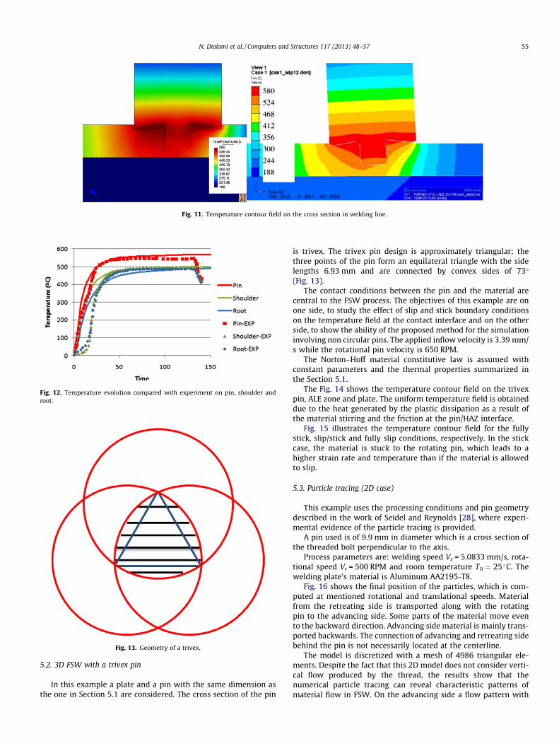
Fig. 11. Temperature contour field on the cross section in welding line.
Fig. 12. Temperature evolution compared with experiment on pin, shoulder androot.
Fig. 13. Geometry of a trivex.
N. Dialami et al. / Computers and Structures 117 (2013) 48–57 55
5.2. 3D FSW with a trivex pin
In this example a plate and a pin with the same dimension asthe one in Section 5.1 are considered. The cross section of the pin
is trivex. The trivex pin design is approximately triangular; thethree points of the pin form an equilateral triangle with the sidelengths 6.93 mm and are connected by convex sides of 73�(Fig. 13).
The contact conditions between the pin and the material arecentral to the FSW process. The objectives of this example are onone side, to study the effect of slip and stick boundary conditionson the temperature field at the contact interface and on the otherside, to show the ability of the proposed method for the simulationinvolving non circular pins. The applied inflow velocity is 3.39 mm/s while the rotational pin velocity is 650 RPM.
The Norton–Hoff material constitutive law is assumed withconstant parameters and the thermal properties summarized inthe Section 5.1.
The Fig. 14 shows the temperature contour field on the trivexpin, ALE zone and plate. The uniform temperature field is obtaineddue to the heat generated by the plastic dissipation as a result ofthe material stirring and the friction at the pin/HAZ interface.
Fig. 15 illustrates the temperature contour field for the fullystick, slip/stick and fully slip conditions, respectively. In the stickcase, the material is stuck to the rotating pin, which leads to ahigher strain rate and temperature than if the material is allowedto slip.
5.3. Particle tracing (2D case)
This example uses the processing conditions and pin geometrydescribed in the work of Seidel and Reynolds [28], where experi-mental evidence of the particle tracing is provided.
A pin used is of 9.9 mm in diameter which is a cross section ofthe threaded bolt perpendicular to the axis.
Process parameters are: welding speed Vs = 5.0833 mm/s, rota-tional speed Vr = 500 RPM and room temperature T0 ¼ 25 C. Thewelding plate’s material is Aluminum AA2195-T8.
Fig. 16 shows the final position of the particles, which is com-puted at mentioned rotational and translational speeds. Materialfrom the retreating side is transported along with the rotatingpin to the advancing side. Some parts of the material move evento the backward direction. Advancing side material is mainly trans-ported backwards. The connection of advancing and retreating sidebehind the pin is not necessarily located at the centerline.
The model is discretized with a mesh of 4986 triangular ele-ments. Despite the fact that this 2D model does not consider verti-cal flow produced by the thread, the results show that thenumerical particle tracing can reveal characteristic patterns ofmaterial flow in FSW. On the advancing side a flow pattern with

Fig. 14. Temperature field from left to right on trivex pin, ALE zone and plate.
Fig. 15. Temperature contour field from left to right with fully stick, stick/slip and fully slip condition.
Fig. 16. Tracer visualization, simulation (left) experiment (right).
56 N. Dialami et al. / Computers and Structures 117 (2013) 48–57
sawing shape is seen, which qualitatively correlates with the exper-imental data. This result is encouraging and prompted us to con-struct a three dimensional model.
6. Summary and conclusions
In the current paper, a thermo-mechanical model for FSW sim-ulation is proposed. Thermal analysis is assumed to be transient

N. Dialami et al. / Computers and Structures 117 (2013) 48–57 57
while a quasi-static approximation is used for the mechanicalproblem.
The apropos kinematic framework based on the combination ofALE, Eulerian and Lagrangian descriptions proposed in this workfor different parts of the computational domain is found to beadvantageous. It allows treating arbitrary pin geometries and con-veniently applying the boundary conditions. A mesh moving strat-egy chosen for the ALE part of the domain facilitates coupling withthe rest of the sub-domains (Lagrangian and Eulerian ones).
A Norton–Hoff rigid thermo-visco-plastic constitutive equationis used to characterize the material. The thermal contact and heatconvection-radiation through the boundaries are considered. Heatgenerated by plastic dissipation and friction is taken into account.The effect of slip and stick boundary conditions is studied.
The material stirring is simulated by means of particle tracingmethod. The trends observed are consistent with the results ofexperiments, showing motion of markers inserted into the weld.
In spite of the inherent complexities of the friction stir weldingmodeling (including constitutive and transient heat equations, var-ious boundary conditions, etc.), the obtained numerical results pro-vide some confidence that the method proposed here is apromising numerical tool for simulating FSW. This paper demon-strates the capability of the proposed numerical model to effi-ciently simulate different types of material flows that areencountered in FSW, and accurately compute the resulting ther-mo-mechanical fields.
References
[1] Packer SM, Nelson TW, Sorensen CD. Tool and equipment requirements forfriction stir welding ferrous and other high melting temperature alloys. In: Thethird international symposium on friction stir welding, Kobe, Japan; 2001.
[2] Dong P, Lu F, Hong J, Cao Z. Analysis of weld formation process in friction stirwelding. In: The second international symposium on friction stir welding,Gothenburg, Sweden; 2000.
[3] Askari A, Silling S, London B, Mahoney M. Modeling and analysis of friction stirwelding processes. In: The fourth international symposium on friction stirwelding, GKSS workshop, Park City, Utah, USA; 2003.
[4] Prime MB, Gnäupel-Herold T, Baumann JA, Lederich RJ, Bowden DM, SebringRJ. Residual stress measurement in a thick, dissimilar aluminum alloy frictionstir weld. Acta Mater 2006;54:4013–21.
[5] De Giorgi M, Scialpi A, Panella F, De Filippis L. Effect of shoulder geometry onresidual stress and fatigue properties of AA6082 FSW joints. J Mech Sci Technol2009;23:26–35.
[6] Dattoma V, De Giorgi M, Nobile R. On the residual stress field in the aluminumalloy FSW joints. Strain 2009;45:380–6.
[7] Chen C, Kovacevic R. Thermomechanical modeling and force analysis of frictionstir welding by the finite element method. Proc Inst Mech Eng Part C J MechEng Sci 2004;218:509–19.
[8] Cho J, Boyce D, Dawson P. Modeling strain hardening and texture evolution infriction stir welding of stainless steel. Mater Sci Eng 2005;A398:146–63.
[9] Chenot JL, Massoni E. Finite element modeling and control of new metalforming processes. J Mach Tools Manuf 2006;46:1194–200.
[10] Buffa G, Hu J, Shivpuri R, Fratini L. Design of the friction stir welding tool usingthe continuum based FEM model. Mater Sci Eng 2006;A419:381–8.
[11] Buffa G, Hu J, Shivpuri R, Fratini L. A continuum based fem model for frictionstir welding-model development. Mater Sci Eng 2006;A419:389–96.
[12] Nandan R, Roy GG, Lienert TJ, DebRoy T. Numerical modeling of 3D plastic flowand heat transfer during friction stir welding of stainless steel. Sci TechnolWeld Joining 2006;11:526–37.
[13] Nandan R, Roy GG, Lienert TJ, DebRoy T. Three-dimensional heat andmaterial flow during friction stir welding of mild steel. Acta Mater2007;55:883–95.
[14] Assidi M, Fourment L, Guerdoux S, Nelson T. Friction model for friction stirwelding process simulation: calibrations from welding experiments. Int JMach Tools Manuf 2010;50(2):143–55.
[15] Buffa G, Ducato A, Fratini L. Numerical procedure for residual stressesprediction in friction stir welding. Finite Elem Anal Des 2011;47:470–6.
[16] Guerdoux S, Fourment L. A 3D numerical simulation of different phases offriction stir welding. Model Simul Mater Sci Eng 2009;17:075001.
[17] Ulysse P. Three-dimensional modeling of the friction stir welding process. Int JMach Tools Manuf 2002;42:1549–57.
[18] Norton FH. The creep of steel at high temperature. New York, USA: Mc GrawHill; 1929.
[19] Hoff HJ. Approximate analysis of structures in presence of moderately largecreep deformation quart. Appl Math 1954;12:49–55.
[20] Agelet de Saracibar C, Chiumenti M, Valverde Q, Cervera M. On the orthogonalsubgrid scale pressure stabilization of finite deformation J2 plasticity. ComputMeth Appl Mech Eng 2006;195:1224–51.
[21] Chiumenti M, Valverde Q, Agelet de Saracibar C, Cervera M. A stabilizedformulation for elasticity using linear displacement and pressureinterpolations. Comput Meth Appl Mech Eng 2002;191:5253–64.
[22] Chiumenti M, Valverde Q, Agelet de Saracibar C, Cervera M. A stabilizedformulation for incompressible plasticity using linear triangles and tetrahedra.Int J Plast 2004;20:1487–504.
[23] Cervera M, Chiumenti M, Valverde Q, Agelet de Saracibar C. Mixed linear/linearsimplicial elements for incompressible elasticity and plasticity. Comput MethAppl Mech Eng 2003;192:5249–63.
[24] Agelet de Saracibar C, Cervera C, Chiumenti M. On the formulation of coupledthermoplastic problems with phase-change. Int J Plast 1999;15:1–34.
[25] Cervera C, Agelet de Saracibar C, Chiumenti M. Thermo-mechanical analysisof industrial solidification processes. Int J Numer Meth Eng 1999;46:1575–91.
[26] Johnson W, Kudo HK. The mechanics of extrusion. Manchester,UK: Manchester University Press; 1962.
[27] Guerdoux S. Numerical simulation of the friction stir weldingprocess. ParisTech; 2007.
[28] Seidel TU, Reynolds AP. Visualization of the material flow in AA2195 frictionstir welds using a marker insert technique. Metall Mater Trans 2001;A32:2879–84.