an approach to map sequential applications onto multi-processor
TRANSCRIPT

An Approach to Map Sequential Applicationsonto Multi-Processor Platforms
Giso Dal (0752975)
August 29, 2010
1
Contents
1 Introduction 3
2 Background 32.1 Kahn Process Networks . . . . . . . . . . . . . . . . . . . . . . 42.2 Polyhedrons . . . . . . . . . . . . . . . . . . . . . . . . . . . . 42.3 Tool Flow . . . . . . . . . . . . . . . . . . . . . . . . . . . . . 8
3 Implementation 113.1 Goals . . . . . . . . . . . . . . . . . . . . . . . . . . . . . . . . 113.2 Updated Tool Flow . . . . . . . . . . . . . . . . . . . . . . . . 12
3.2.1 Overview . . . . . . . . . . . . . . . . . . . . . . . . . 123.3 Process Network Transformations . . . . . . . . . . . . . . . . 19
3.3.1 Plane Cut . . . . . . . . . . . . . . . . . . . . . . . . . 233.3.2 Modulo Unfolding . . . . . . . . . . . . . . . . . . . . . 253.3.3 Merge . . . . . . . . . . . . . . . . . . . . . . . . . . . 28
3.4 Assumptions . . . . . . . . . . . . . . . . . . . . . . . . . . . . 303.5 Unimplemented . . . . . . . . . . . . . . . . . . . . . . . . . . 313.6 Implementation Problems . . . . . . . . . . . . . . . . . . . . 333.7 Usage . . . . . . . . . . . . . . . . . . . . . . . . . . . . . . . 343.8 Partition File . . . . . . . . . . . . . . . . . . . . . . . . . . . 34
4 Experiments 36
5 Conclusion 38
2

Abstract
Sequentially specified applications are not optimized to run on multi-processor platforms. Kahn Process Networks can be used to representa sequential application and with it, we are able to compute a mappingonto a multi-processor platform. A Kahn Process Network is a graphrepresentation in which the nodes represent the function calls (or pro-cesses) of the sequential application, and the edges are unboundedFIFO channels. Respecting the dependencies which are analyzed bythe PN compiler, process partitioning transformations can be appliedto optimize the network for a given platform. Three different transfor-mations have been implemented and will be discussed, namely planecut, modulo unfolding and merge.
1 Introduction
The partitioning process of sequential components is both time-consumingand difficult. The Kahn Process Network model of computation is used as arepresentation of sequential nested-loop programs: each node in the networkcorresponds to a function call statement in the sequential application. Com-pilers produce the control code for the synchronization of the partitioned pro-cesses, ensuring correct execution. In Section 2 some background is discussedwhich is be needed to understand the transformations. The implementationuses other tools, like PN[4] and CLooG[2]. In Section 3 the implementationis discussed, giving an overview of the tool flow using the tools and a de-tailed description of the inner workings of the transformation software. Also,three different transformation techniques are explained by example in thissection. The transformation software has been tested, of which the resultsare discussed in Section 4.
2 Background
Before the implementation of the partitioning software is discussed, someknowledge is needed to understand how it works. Kahn Process Networks areexplained and polyhedrons which describe iteration domains. Afterwards, theinitial tool flow is given, along with a short description of each component.
3

2.1 Kahn Process Networks
Kahn Process Networks[3] is a distributed model of computation for sequen-tial processes which communicate through unbounded FIFO channels deter-ministically. The network is not dependent on computation or communica-tion delays, making it useful for modeling embedded systems. In our case, thenodes represent the function calls. An example of a Kahn Process Networkis given in Figure 1.
Figure 1: A Kahn process network of three processes without feedback com-munication. Edges A, B and C are communication channels. One of theprocesses is named process P.
2.2 Polyhedrons
A subset of sequentially specified applications can be represented by thePolyhedral model. We use this model to create a mapping to multi-processorplatforms. Each function call in a sequential application has a domain. Thisdomain can be translated into a polylib matrix consisting of integers, whichwe will refer to as a polyhedron. The syntax of a row in a polyhedron isconsistent and can be viewed as follows, when using n iterators I and mparameters P : ≥ / = I1 I.. In−1 In P1 P.. Pm−1 Pm constant
.. a .. b c d .. e f g
.. .. .. .. .. .. .. .. .. ..
4

Where a-g ∈ Z. The first and last column always represent the same. Thefirst column contains either the number 1 which stands for ≥ or the number0 which stands for =. After the first column, the iterators that are used inthe program are enumerated. After the iterators, the parameters are enu-merated which make the domain of a function call variable. The last col-umn is a constant integer. The meaning of each row can be derived whentaking the addition of every column. The above polyhedron translates toa ·I1 + .. + b ·In−1 + c ·In + d ·P1 + .. + e ·Pm−1 + f cdotPm + g >= 0,given that the first column contains 1. With this in mind we can create theneeded functions that represent the domain of a function call. Take for ex-ample the following C-style code:
void f u n c t i o n c a l l ( ) ;
int i ;for ( i = 0 ; i < 100 ; i = i + 1){
f u n c t i o n c a l l ( ) ;}
When we look at the function function call(), we can see that it is repeated100 times, due to the for loop and its iterator i. The domain D of this state-ment can be written as {0 ≤ i ∧ i ≤ 99}. This can be translated intoa polyhedron of two rows when we split our domain in to two inequalitieswhich cover the entire domain. These inequalities are {0 ≤ i} and {i ≤ 99}.One row must represent the lower bound of iterator i and the other row mustrepresent the upper bound of iterator i. ≥ / = i constant
1 1 01 −1 99
We will now compute the meaning of each row by taking the addition ofevery column. The first row is translated into
1 · i + 0 ≥ 0
≡ i ≥ 0
5
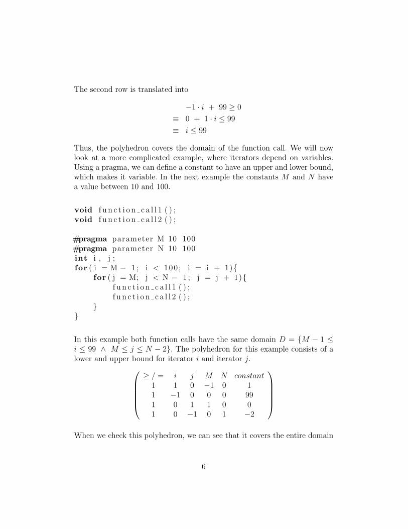
The second row is translated into
−1 · i + 99 ≥ 0
≡ 0 + 1 · i ≤ 99
≡ i ≤ 99
Thus, the polyhedron covers the domain of the function call. We will nowlook at a more complicated example, where iterators depend on variables.Using a pragma, we can define a constant to have an upper and lower bound,which makes it variable. In the next example the constants M and N havea value between 10 and 100.
void f u n c t i o n c a l l 1 ( ) ;void f u n c t i o n c a l l 2 ( ) ;
#pragma parameter M 10 100#pragma parameter N 10 100int i , j ;for ( i = M − 1 ; i < 100 ; i = i + 1){
for ( j = M; j < N − 1 ; j = j + 1){f u n c t i o n c a l l 1 ( ) ;f u n c t i o n c a l l 2 ( ) ;
}}
In this example both function calls have the same domain D = {M − 1 ≤i ≤ 99 ∧ M ≤ j ≤ N − 2}. The polyhedron for this example consists of alower and upper bound for iterator i and iterator j.
≥ / = i j M N constant1 1 0 −1 0 11 −1 0 0 0 991 0 1 1 0 01 0 −1 0 1 −2
When we check this polyhedron, we can see that it covers the entire domain
6
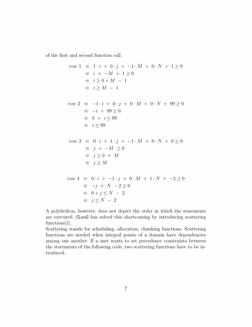
of the first and second function call.
row 1 ≡ 1 · i + 0 · j + −1 ·M + 0 ·N + 1 ≥ 0
≡ i + −M + 1 ≥ 0
≡ i ≥ 0 +M − 1
≡ i ≥M − 1
row 2 ≡ −1 · i + 0 · j + 0 ·M + 0 ·N + 99 ≥ 0
≡ −i + 99 ≥ 0
≡ 0 + i ≤ 99
≡ i ≤ 99
row 3 ≡ 0 · i + 1 · j + −1 ·M + 0 ·N + 0 ≥ 0
≡ j + −M ≥ 0
≡ j ≥ 0 + M
≡ j ≥M
row 4 ≡ 0 · i + −1 · j + 0 ·M + 1 ·N + −2 ≥ 0
≡ −j + N − 2 ≥ 0
≡ 0 + j ≤ N − 2
≡ j ≤ N − 2
A polyhedron, however, does not depict the order in which the statementsare executed. CLooG has solved this shortcoming by introducing scatteringfunctions[1].Scattering stands for scheduling, allocation, chunking functions. Scatteringfunctions are needed when integral points of a domain have dependenciesamong one another. If a user wants to set precedence constraints betweenthe statements of the following code, two scattering functions have to be in-troduced.
7

void f u n c t i o n c a l l 1 ( int x ) ;void f u n c t i o n c a l l 2 ( int x ) ;
int i ;for ( i = 1 ; i <= N; i ++){
f u n c t i o n c a l l 1 ( i ) ;}for ( i = 1 ; i <= N; i ++){
f u n c t i o n s c a l l 2 ( i ) ;}
The scatting functions which depict the order of the function calls in theexample above, are the following:
T_function_call1(i) = (1),
T_function_call2(i) = (2);
This scattering means that each integral point of the domain of function call1()is scanned at logical date 1 while each integral point of the domain of func-tion call2() is scanned at logical date 2. As a result, all instances of func-tion call1() are executed before the instances of function call2().The user can define any order of the function evaluations. The scatteringfunctions are defined for every domain and can be multi-dimensional. Whenwe look at the more complicated example code, that was given for whichpolyhedrons where created, the scattering functions are given by:
T_function_call1(i,j) = (0,i,0,j,0),
T_function_call2(i,j) = (0,i,0,j,1);
We will however not concern ourselves with scattering functions, becausethese handle dependencies that will be analyzed by one of the tools that isused when performing transformations on sequential applications.
2.3 Tool Flow
The process partitioning software uses other tools. The initial tool flow isgiven in Figure 2, after which the tools that have been used will be discussed.
8

Figure 2: Initial tool flow
C2PDG
C2PDG takes as input a sequential program written in C. Only a subset of Cis supported. There are a couple of restrictions, which will now be listed.
• Only function calls are valid statements
• Function calls have no return value
– All functions are declared void, outputs are handled by functionarguments
– Function arguments which are declared as pointers to a type, areoutputs
– Function arguments which are not declared as pointers to a type,are inputs
9

The tool then takes this C input file and generates a Polyhedral DependenceGraph or PDG, without the dependency information. A PDG is a KahnProcess Network in which every node represents a function call from the inputfile. The data structure which represents the PDG includes the line numberof each function call and their domain, which is a polyhedron. Also, a prefixis generated that indicates the position of each function call in relation toother function calls. With the prefix we can also reproduce if, for instance, thefunction call is located in an if statement within a for loop. The generatedPDG is then written as a YAML formatted output file.
PN
The PN[4] compiler takes the output of C2PDG and adds the data dependencyinformation to the PDG. It takes the YAML file and stores the informationin a data structure similar to the data structure C2PDG uses. The dependen-cies are analyzed and inserted into the data structure. Afterwards, the nowcomplete PDG is also outputted as a YAML file. Optionally, the output filegenerated by PN can be passed to DOTTY, which creates a visual representa-tion of the PDG. The ESPAM tool can be used to map the PDG to a givenplatform.
CLooG
CLooG[2] stands for Chunky Loop Generator. Although not present in thetool flow presented, CLooG is used in the tool chain. We do not look at theextended tool chain, as it is not important for the the implementation of thepartitioning software. C2PDG generates polyhedra for the iteration domainsof C code. CLooG does the opposite. It takes the polyhedra and generatesfor loops, if statements and function calls, i.e. C code. We need this func-tionality when implementing the partitioning software. CLooG is speciallydesigned to avoid control overhead and to produce very efficient code.
10

3 Implementation
The implementation of the process partitioning software uses other tools,which are written in the programming language C. Therefore, the partition-ing software is also written in C. For convenience, the process partitioningsoftware is referred to as handle from now on. In this section the tool flowand each tool used will be discussed. Also, each implemented transformationwill be explained. Afterwards, we discuss the assumptions that have beenmade and possible improvements that can be made.
3.1 Goals
The initial goal was to make an implementation to automatically createa mapping of sequential applications onto multi-processor platforms usingKahn Process Networks. A list of steps describes all the tasks that need tobe performed.
1. sequential application ⇒ PDG
2. loop until all partition combinations have been generated
(a) partition PDG
(b) evaluate partitioned PDG
(c) remember best evaluated partitioning
3. best evaluated partitioning ⇒ partitioned application
Unfortunately, this proved to be too time consuming to implement, withthe given time constraints. What handle has been programmed to do, is topartition sequential software by manual input and generate the partitionedsequential application, which results in the following tasks.
1. sequential application ⇒ PDG
2. analyze manually written transformation input
3. perform transformation on PDG
4. generate partitioned sequential application
11

3.2 Updated Tool Flow
This section discusses the updated tool flow. First, a flow chart is given.Afterwards, each component is discussed individually (except for the compo-nents of the original tool flow).
Figure 3: Tool Flow with partitioning software
3.2.1 Overview
The input C File is passed to C2PDG, which creates a YAML formatted outputfile with the information of the PDG, without the dependency information.PN parses the file generated by C2PDG, and transfers the information into aPDG data structure. Without having analyzed the dependencies, the PDGis passed to Handle. Handle parses the manually written Partition File anduses it to apply transformations on the PDG, when there are plane cutsor modulo unfoldings among the transformations. The optionally partitionedPDG is passed back to PN for dependency analysis. The now complete PDG is
12

passed back to Handle. Before writing the output file, merge transformationsare handled by creating a mapping for the CLooG tool. This will be discussedlater. C2PDG creates polyhedrons for every function call. These polyhedronsneed to be changed back to valid C code. This is what CLooG does. Handlepasses the polyhedrons of the PDG to CLooG with the CLooG File, whichthen generates for and if statements accordingly. CLooG however, does nothave the actual function calls. It only knows the number of the functioncall. Handle takes the generated code and the numbers of the function callsthat CLooG wants to print. It then opens the input C File and looks upthe function call with the line number that is specified in the PDG, whichis then printed instead of the number of the function call. This alone doesnot generate a valid C file, so all lines of the input C File before the mainfunction are copied to the output C File accompanied by the declarations ofall variables used by the program.
CLooG
CLooG takes an input file. The CLooG File consists of three main parts. Acontext section, a statement section and a section for the scattering func-tions. When the symbol # occurs, the right hand side is a comment. Thecontext section contains the programming language and all parameters thatare used. Also, an option is given to enter the parameter names manually. Forfuture purposes, we will use the following example throughout the remainedof this article.
13

void f u n c t i o n c a l l 1 ( int ∗x , int y ) ;void f u n c t i o n c a l l 2 ( int ∗x , int y ) ;void f u n c t i o n c a l l 3 ( int ∗x , int y ) ;
int i , j , z ;for ( i = 0 ; i < 10 ; i = i + 1){
for ( j = 0 ; j < 10 ; j = j + 1){f u n c t i o n c a l l 1 (&z , z ) ;f u n c t i o n c a l l 2 (&z , z ) ;f u n c t i o n c a l l 3 (&z , z ) ;
}}
In our case, no parameters are used, creating the following block.
# ------------ CONTEXT ---------------
C # programing language
# context polyhedron:
1 2 # 1 row, 2 columns
1 0 # 0 >= 0, always true
0 # do not set parameter names manually
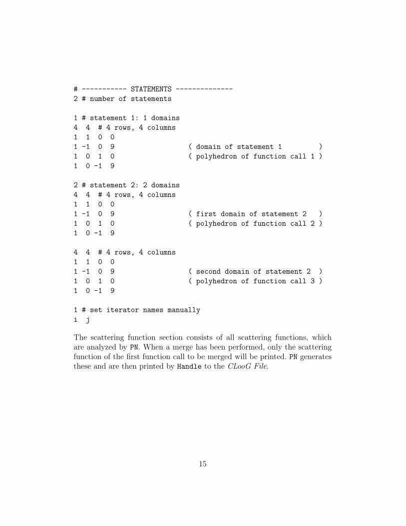
The statement section consists of all the function call polyhedrons. It is thefirst time the number of domains per statement pops up. This option is usedfor the merge transformation. When merging nodes, the polyhedrons will beprinted as domains of one statement. For instance, when we merge the secondand third function call of our example code, the CLooG File will contain thefollowing.
14
# ----------- STATEMENTS --------------
2 # number of statements
1 # statement 1: 1 domains
4 4 # 4 rows, 4 columns
1 1 0 0
1 -1 0 9 ( domain of statement 1 )
1 0 1 0 ( polyhedron of function call 1 )
1 0 -1 9
2 # statement 2: 2 domains
4 4 # 4 rows, 4 columns
1 1 0 0
1 -1 0 9 ( first domain of statement 2 )
1 0 1 0 ( polyhedron of function call 2 )
1 0 -1 9
4 4 # 4 rows, 4 columns
1 1 0 0
1 -1 0 9 ( second domain of statement 2 )
1 0 1 0 ( polyhedron of function call 3 )
1 0 -1 9
1 # set iterator names manually
i j
The scattering function section consists of all scattering functions, whichare analyzed by PN. When a merge has been performed, only the scatteringfunction of the first function call to be merged will be printed. PN generatesthese and are then printed by Handle to the CLooG File.
15

# -------------- SCATTERING -------------
2 # number of functions
# statement 1
2 6 # 2 rows, 6 column
0 1 0 -1 0 0
0 0 1 0 -1 0
# statement 2
2 6 # 2 rows, 6 columns
0 1 0 -1 0 0
0 0 1 0 -1 0
0 # do not set scattering names manually
CLooG generates for every statement for loops and if statements accordingly,with this input file. For more information on CLooG input files, please visitthere website[1].
Handle
Handle is called two times. Once before dependency analysis of PN, handlingthe plane cut and modulo unfolding, and once after, for the merge transfor-mations. When performing a plane cut or modulo unfolding, the PDG mustbe updated. The node we want to partition is multiplied by the partitionfactor, which is explained in Section 3.3. Polyhedrons are updated accord-ingly. Because the actual number of function calls does not increase, but thenumber of nodes in the PDG do, a mapping needs to be created from thenodes in the PDG to the actual function calls. This mapping is then lateron used to print the correct function call to the output C File. The nodenumbering starts from 0 and the function calls starts from 1. For instance, ifwe have three function calls, Table 1 contains the original mapping. When weapply a transformation like a plane cut with factor 2 on node 1, the resultingmapping table is displayed in Table 2.
16

Node Function Call
0 11 22 3
Table 1: Original Mapping
Node Function Call
0 11 22 23 3
Table 2: Updated Mapping
For the plane cut, the prefix needs to updated as well. A prefix is defined forevery function call and tells us about the structure of the program and morespecifically, where a function call takes place. For instance, from the prefixof a function call we can derive that a given function call is situated as thesecond function call in the body of an if statement within the body of a forloop, and so on. A prefix is a series of numbers where three rules apply whencreating one.
1. When a function call is encountered:
(a) 1 is appended if there is no function call counter
(b) else, 2 is added to the previous count
2. When a for loop is encountered:
(a) 1 is appended if the preceding number is −1 or if there are nonumbers
(b) −1 is appended
3. When a if statement is encountered:
(a) 1 is appended if the preceding number is −1 (for loop indicator)in all prefixes with the same domain
17

To give an example, prefixes are generated for the running example and thefollowing code, on which a plane cut transformation has been performed. Theplane cut transformation will be explained in the next section.
void f u n c t i o n c a l l 1 ( int ∗x , int y ) ;void f u n c t i o n c a l l 2 ( int ∗x , int y ) ;void f u n c t i o n c a l l 3 ( int ∗x , int y ) ;
int i , j , z ;for ( i = 0 ; i < 10 ; i ++){
f u n c t i o n c a l l 1 (&z , z ) ; // node 0
i f ( i >= 0 && i <= 4)f u n c t i o n c a l l 2 (&z , z ) ; // node 1
i f ( i >= 5 && i <= 9)f u n c t i o n c a l l 2 (&z , z ) ; // node 2
f u n c t i o n c a l l 3 (&z , z ) // node 3}
• Prefix of running example
– node 0: [1, -1, 1]
– node 1: [1, -1, 3]
– node 2: [1, -1, 5]
– node 3: [1, -1, 7]
• Prefix of partitioned example
– node 0: [1, -1, 1, 1]
– node 1: [1, -1, 1, 3, 1]
– node 2: [1, -1, 1, 5, 1]
– node 3: [1, -1, 1, 7]
18
3.3 Process Network Transformations
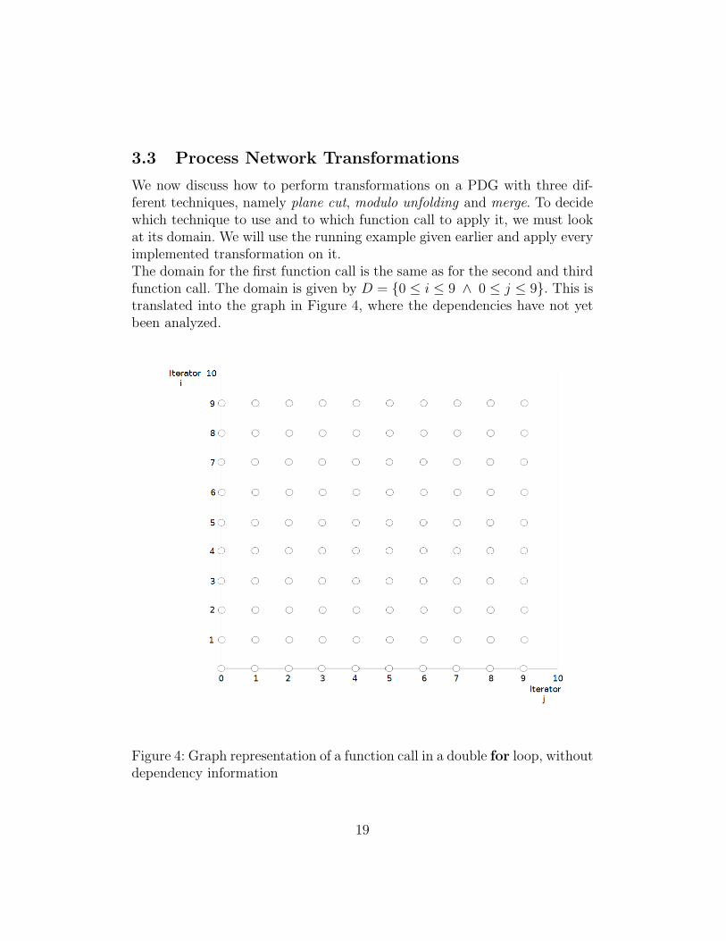
We now discuss how to perform transformations on a PDG with three dif-ferent techniques, namely plane cut, modulo unfolding and merge. To decidewhich technique to use and to which function call to apply it, we must lookat its domain. We will use the running example given earlier and apply everyimplemented transformation on it.The domain for the first function call is the same as for the second and thirdfunction call. The domain is given by D = {0 ≤ i ≤ 9 ∧ 0 ≤ j ≤ 9}. This istranslated into the graph in Figure 4, where the dependencies have not yetbeen analyzed.
Figure 4: Graph representation of a function call in a double for loop, withoutdependency information
19

Every point in the graph in Figure 4 represents one iteration of the func-tion call. When assuming there are no dependencies between the functioncalls, the domain can be partitioned in any way we see fit. Every partitioningcreated can be executed concurrently. If we need to map the sequential ap-plication onto a multi-processor platform which has two processors, we candivide the domain in two equal halves and run them concurrently withoutcommunication between the two processors. When we look at the PDG rep-resentation in Figure 5 of the given code, we want to create concurrent nodes.
Figure 5: Kahn Process Network of example code
If a program does not contain concurrent elements, we assume it executesentirely on one processor. When having two processors, this is not optimal.One processor does all the work, while the other is idle. If we partition thesecond function call, we create the PDG in Figure 6, which now containsnodes (function calls) that can be executed concurrently. As a result, onepartition can be executed on one processor, while the other partition can beexecuted on the other processor, optimizing workload distribution.
20

Figure 6: Partitioned Kahn Process Network of example code
When we analyze the dependencies, we have to be smart about partition-ing the domain. The goal is to create partitions that are as independent aspossible to ensure minimal communication between processors when havingmapped the sequential application. Figure 7 holds the same domain withdependencies information.
21
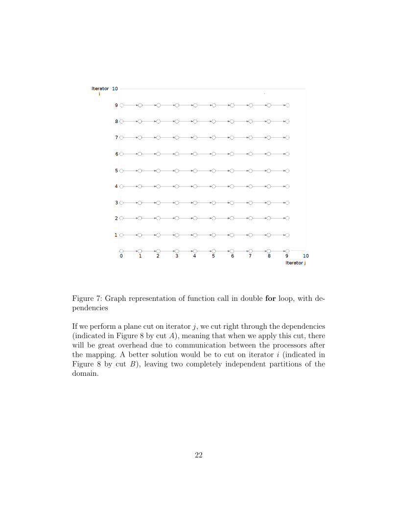
Figure 7: Graph representation of function call in double for loop, with de-pendencies
If we perform a plane cut on iterator j, we cut right through the dependencies(indicated in Figure 8 by cut A), meaning that when we apply this cut, therewill be great overhead due to communication between the processors afterthe mapping. A better solution would be to cut on iterator i (indicated inFigure 8 by cut B), leaving two completely independent partitions of thedomain.
22

Figure 8: Cut on iterator i and iterator j
3.3.1 Plane Cut
We apply a plane cut on the second function call of the given example code.By applying a transformation to the polyhedron of that function call, theoutput code we want to obtain is the following:
23

void f u n c t i o n c a l l 1 ( int ∗x , int y ) ;void f u n c t i o n c a l l 2 ( int ∗x , int y ) ;void f u n c t i o n c a l l 3 ( int ∗x , int y ) ;
int i , j , z ;for ( i = 0 ; i < 10 ; i = i + 1){
for ( j = 0 ; j < 10 ; j = j + 1){f u n c t i o n c a l l 1 (&z , z ) ;
i f ( i >= 0 && i <= 4)f u n c t i o n c a l l 2 (&z , z ) ;
i f ( i >= 5 && i <= 9)f u n c t i o n c a l l 2 (&z , z ) ;
f u n c t i o n c a l l 3 (&z , z ) ;}
}
We need to add a new node to the PDG, just like Figure 6. Afterwards, thepolyhedrons of the added nodes and the polyhedron of the node we applythe transformation to, need to be changed accordingly. We start of with thepolyhedron of the second function call (this is the same polyhedron as thepolyhedrons of the other function calls).
≥ / = i j constant1 1 0 01 −1 0 91 0 1 01 0 −1 9
The domain of iterator i of the function call is D = {0 ≤ i ≤ 9}. Handle isimplemented in a way that you have to give a factor with which you wantto divide the domain. The domain is then divided in equal partitions. Whenapplying a plane cut with factor two on iterator i (for instance, if you have twoprocessors), we have to split its domain in two equal parts. Two polyhedronshave to be created, with the domain D of iterator i given by D = D1 ∪D2
and D1 ∩ D2 = ∅, where D1 = {0 ≤ i ≤ 4} and D2 = {5 ≤ i ≤ 9}. The
24

polyhedron with domain D1 would be:≥ / = i j constant
1 1 0 01 −1 0 41 0 1 01 0 −1 9
The polyhedron with domain D2 would be:
≥ / = i j constant1 1 0 51 −1 0 91 0 1 01 0 −1 9
3.3.2 Modulo Unfolding
Again we use the second function call to partition. A modulo unfolding par-titions the PDG, similar to a plane cut. The resulting PDG is given in Figure6. The resulting code is shown below.
void f u n c t i o n c a l l 1 ( int ∗x , int y ) ;void f u n c t i o n c a l l 2 ( int ∗x , int y ) ;void f u n c t i o n c a l l 3 ( int ∗x , int y ) ;
int i , j , z ;for ( i = 0 ; i < 10 ; i = i + 1){
for ( j = 0 ; j < 10 ; j = j + 1){f u n c t i o n c a l l 1 (&z , z ) ;i f ( i % 2 == 0)
f u n c t i o n c a l l 2 (&z , z ) ;i f ( i % 2 == 1)
f u n c t i o n c a l l 2 (&z , z ) ;f u n c t i o n c a l l 3 (&z , z ) ;
}}
25

As the name suggests, modulo if statements are inserted according to thepartition factor, which in our case is two. The polyhedrons that need tobe created are not as obvious as the ones for a plane cut. An extra iteratorneeds to be added, which is used to express the modulo operator. The originalpolyhedron of the second function call is the following.
≥ / = i j constant1 1 0 01 −1 0 91 0 1 01 0 −1 9
When adding another iterator m to the polyhedron, a column needs to addedin the right place. The description of m can be found in Section 3.4. Alsoa row needs to be added specifying the domain of this extra iterator, whichincludes an indication for the iterator we partition, creating the followingpolyhedron.
≥ / = i j m constant0 −1 0 2 x1 1 0 0 y1 −1 0 0 z1 0 1 0 01 0 −1 0 9
The value in the column of the first row is the factor with which we partitionthe domain of the function call. Only the constants x, y and z need adjusting.The constants follow a pattern for each polyhedron representing a modulo ifstatement, which is represented by the following function.
int x , y , z ;modulo po lyhedron constants ( int n , int f a c t o r ){
x = n − 1 ;y = y − ( f a c t o r − n ) ;z = z − (n − 1 ) ;
}
Where factor is the partition factor and n represents the nth polyhedron
26
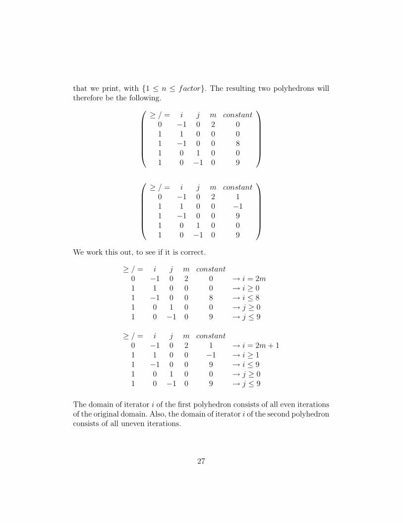
that we print, with {1 ≤ n ≤ factor}. The resulting two polyhedrons willtherefore be the following.
≥ / = i j m constant0 −1 0 2 01 1 0 0 01 −1 0 0 81 0 1 0 01 0 −1 0 9
≥ / = i j m constant
0 −1 0 2 11 1 0 0 −11 −1 0 0 91 0 1 0 01 0 −1 0 9
We work this out, to see if it is correct.
≥ / = i j m constant0 −1 0 2 0 → i = 2m1 1 0 0 0 → i ≥ 01 −1 0 0 8 → i ≤ 81 0 1 0 0 → j ≥ 01 0 −1 0 9 → j ≤ 9
≥ / = i j m constant0 −1 0 2 1 → i = 2m+ 11 1 0 0 −1 → i ≥ 11 −1 0 0 9 → i ≤ 91 0 1 0 0 → j ≥ 01 0 −1 0 9 → j ≤ 9
The domain of iterator i of the first polyhedron consists of all even iterationsof the original domain. Also, the domain of iterator i of the second polyhedronconsists of all uneven iterations.
27

3.3.3 Merge
To merge function calls, one has to take the dependencies into account. Whenwe look at the Figure 5 we can see that the function calls are executedin a predefined order due to dependencies. We cannot for instance executefunction call3() before function call2(), as the semantics of the applicationwill change. The merge transformations that can be preformed are denotedby the set S = {{1, 2}, {2, 3}, {1, 2, 3}}, where the numbers represent thefunction calls, respectively. When two or more nodes are merged, only onescattering function is needed to define the order of execution. The scatteringfunction of the first function call is used as scattering function for the mergedfunction calls.Merge has to be handled differently than a plane cut or modulo unfolding.The dependencies need to be known. While in the other cases, they neednot. When performing a merge transformation we do not make changes tothe PDG but change what we write to the CLooG File. For this to work, amapping is needed from the statements that are printed to the CLooG File tothe nodes in the PDG. We start again with the original mapping (Table 3).When we apply the merge transformation to the second and third functioncall, we can see in Table 4 that statement two has two domains, which wecovered earlier.
28

Statement Node
1 02 13 2
Table 3: Original Mapping
Statement Node
1 02 1,2
Table 4: Updated Mapping
The transformation is also passed to the mapping for the function calls. Whenfunction calls are merged, a new function is created. This new function willobviously be declared before the main function. The function names andarguments used by both functions are combined to do so. Within this newlydefined function, the function calls that are merged are called upon in theorder they occurred in the input C File. All function arguments are enu-merated, followed by a unique number. Suppose we take the following twofunction calls:
f u n c t i o n c a l l 2 (&x , x ) ;f u n c t i o n c a l l 3 (&x , y ) ;
When we merge these function calls and fill in the function call arguments,we can see that the previous function calls do no equal the following functioncalls.
void f u n c t i o n c a l l 2 f u n c t i o n c a l l 3 ( int ∗x 1 , int x 2 ,int ∗x 3 , int y 4 ){
f u n c t i o n c a l l 2 (&x 1 , x 2 ) ;f u n c t i o n c a l l 3 (&x 3 , y 4 ) ;
}
29

Whenever we encounter a function call argument which equals another, weuse the first definition of that argument. When outputs are involved, someadditional statements need to be added, i.e. the value of the output argu-ments also need to be equal to the first definition of that argument. Thiscreates the following function, which equals the function calls we began with.
void f u n c t i o n c a l l 2 f u n c t i o n c a l l 3 ( int ∗x 1 , int x 2 ,int ∗x 3 , int y 4 ){
f u n c t i o n c a l l 2 (&x 1 , x 1 ) ;f u n c t i o n c a l l 3 (&x 1 , y 4 ) ;∗x 3 = ∗x 1 ;
}
This approach also works with array arguments.
3.4 Assumptions
All assumptions that have been made during the implementation processhave been listed below.
• input C File
– There is only one statement per line
– Each for loop has an integer iterator and only one iterator
– All functions are declared void
– All functions are declared within the same file as the main func-tion
– All function calls are located in the scope of a for loop
– All variables used are accessible throughout the scope of the mainfunction
– Function arguments are of the following format:
[const] type [*] variable_name
(All items between brackets are optional)
30

– The opening bracket of a for loop is located on the same line andany closing bracket is the only character of its line
• Handle
– The size of the domain of the iterator we want to apply the trans-formation to, must must be divisible by the partition factor(When trying to manually apply the transformations, the outputof the resulting program is incorrect when this assumption is vio-lated)
• Partition File
– All line numbers obey a natural order
– All transformations are disjoint, i.e. only one transformation canbe applied per function call.
3.5 Unimplemented
Due to time constraints the transformation process is not performed auto-matically. A manual component is still present. This was discussed in Section3.1. Another thing that is not implemented is the use of parameters. Eachtransformation uses constants to calculate the resulting polyhedra, which cannot be done when using parameters, because they are variable. The domainof an iterator needs to be defined by these variables. Some calculations areneeded for this. We look at how polyhedrons turn out when using parametersand apply a plane cut transformation. We will use the following code.
#pragma parameter M 10 100#pragma parameter N 10 100void f u n c t i o n c a l l ( ) ;
int i ;for ( i = M + 10 ; i <= N − 10 ; i = i + 1){
f u n c t i o n c a l l ( ) ;}
31
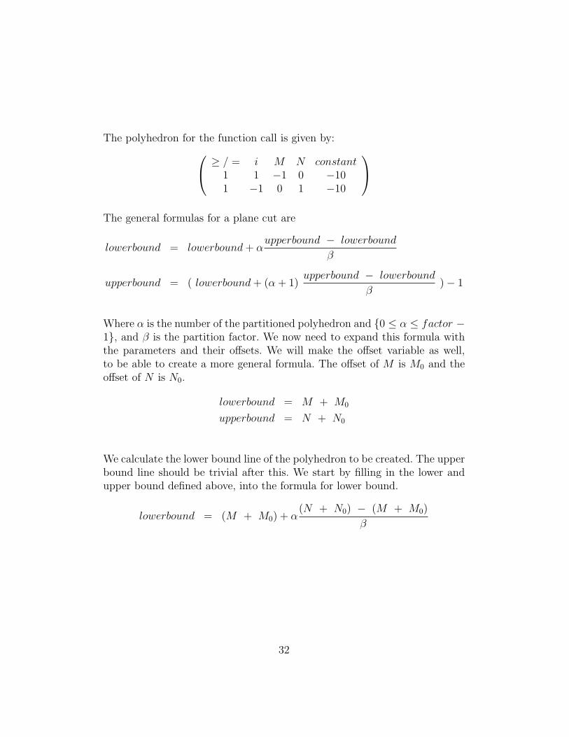
The polyhedron for the function call is given by: ≥ / = i M N constant1 1 −1 0 −101 −1 0 1 −10
The general formulas for a plane cut are
lowerbound = lowerbound+ αupperbound − lowerbound
β
upperbound = ( lowerbound+ (α + 1)upperbound − lowerbound
β)− 1
Where α is the number of the partitioned polyhedron and {0 ≤ α ≤ factor −1}, and β is the partition factor. We now need to expand this formula withthe parameters and their offsets. We will make the offset variable as well,to be able to create a more general formula. The offset of M is M0 and theoffset of N is N0.
lowerbound = M + M0
upperbound = N + N0
We calculate the lower bound line of the polyhedron to be created. The upperbound line should be trivial after this. We start by filling in the lower andupper bound defined above, into the formula for lower bound.
lowerbound = (M + M0) + α(N + N0) − (M + M0)
β
32
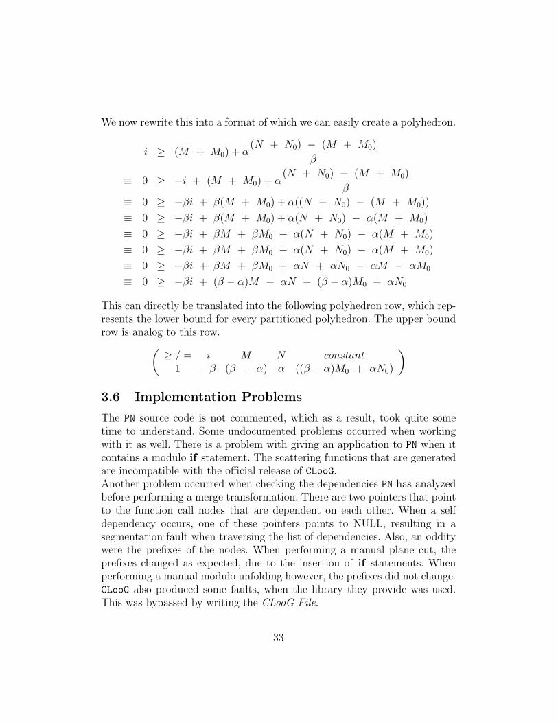
We now rewrite this into a format of which we can easily create a polyhedron.
i ≥ (M + M0) + α(N + N0) − (M + M0)
β
≡ 0 ≥ −i + (M + M0) + α(N + N0) − (M + M0)
β
≡ 0 ≥ −βi + β(M + M0) + α((N + N0) − (M + M0))
≡ 0 ≥ −βi + β(M + M0) + α(N + N0) − α(M + M0)
≡ 0 ≥ −βi + βM + βM0 + α(N + N0) − α(M + M0)
≡ 0 ≥ −βi + βM + βM0 + α(N + N0) − α(M + M0)
≡ 0 ≥ −βi + βM + βM0 + αN + αN0 − αM − αM0
≡ 0 ≥ −βi + (β − α)M + αN + (β − α)M0 + αN0
This can directly be translated into the following polyhedron row, which rep-resents the lower bound for every partitioned polyhedron. The upper boundrow is analog to this row.(
≥ / = i M N constant1 −β (β − α) α ((β − α)M0 + αN0)
)
3.6 Implementation Problems
The PN source code is not commented, which as a result, took quite sometime to understand. Some undocumented problems occurred when workingwith it as well. There is a problem with giving an application to PN when itcontains a modulo if statement. The scattering functions that are generatedare incompatible with the official release of CLooG.Another problem occurred when checking the dependencies PN has analyzedbefore performing a merge transformation. There are two pointers that pointto the function call nodes that are dependent on each other. When a selfdependency occurs, one of these pointers points to NULL, resulting in asegmentation fault when traversing the list of dependencies. Also, an odditywere the prefixes of the nodes. When performing a manual plane cut, theprefixes changed as expected, due to the insertion of if statements. Whenperforming a manual modulo unfolding however, the prefixes did not change.CLooG also produced some faults, when the library they provide was used.This was bypassed by writing the CLooG File.
33

3.7 Usage
The partitioning process can be invoked by calling PN:
./c2pdg FILE.c
./pn -i FILE.yaml -o FILE_pn.yaml
Where FILE is the name of the input file. Input and output files of Handleare:
FILE.part ( input : file containing manually written
transformations )
FILE_out.c ( output: generated C file )
FILE.cloog ( output: file meant for CLooG. Contains
function call polyhedrons and
scattering functions )
3.8 Partition File
The manually written Partition File will be parsed by Handle. Therefore, thefile has a predefined syntax beginning with the number of transformations.No comments in this file are tolerated, though to explain the file, all characteron the right hand side of the # symbol are comments. The syntax for planecutting and modulo unfolding is given by the following.
[plane | modulo]
[line number of function call]
[partition factor]
[iterator of transformation]
The line numbers of the function calls in our running example are 8, 9 and10. The line numbering of a file starts from 1. To indicate on which iteratorto apply the transformation on, we start counting from 1, which is a repre-sentation of the iterator of the outer most for loop. For every following forloop, the count goes up by 1. The file containing the plane cut transformationof the second function call on the first iterator would be the following file.
1 # 1 transformation
plane # transformation type
9 # line of function call
2 # partition factor
1 # iterator of transformation
34

A merge is different, because it does not need a partition factor or iteratornumber to preform a transformation. The syntax is denoted by the following.
[merge]
[line number 1] [..] [line number n]
Where n is the nth node to merge. The line numbers are written on one row,separated by a space character. If we were to merge the first and secondfunction call, the Partition File would look like the following.
1 # 1 transformation
merge # transformation type
8 9 # lines of function calls
Multiple transformations are also supported. A merge of the first two functioncalls and a modulo unfolding on the third function call would look like thefollowing.
2 # 2 partitions
merge # partition type
8 9 # lines of function calls
plane # partition type
10 # line of function call
2 # partition factor
1 # iterator of transformation
There is a limitation to what can be passed to Handle. The line numbers usedin the Partition File must obey a natural order and all transformations mustbe disjoint, meaning no more than one transformation can be performed oneach function call.
35

4 Experiments
Some experiments have been done with an application called sobel. Sobelis an image edge detecting application. It computes an approximation of thegradient of the image intensity function.The experiments have been done on a four core machine (the SILVER serverat the LIACS faculty of Leiden University). Results are shown in Table 5.The Time columns contain the results of the application called Time, whichin our case has as argument the PN application. Table 5 also includes thenumber of rows of the code, which refer to the number of rows of the outputfile within the main function. As a reference, the input program contains29 rows, not including variable declarations nor empty rows. Regarding thetransformations, one transformation has been done at a time with differentpartition factors (indicated by the number on the right hand side of thetransformation type).
36

Transformation Time Lines
None 0:00.56 14Plane (2) 0:00.71 24Plane (4) 0:00.82 36Plane (10) 0:02.85 47Plane (50) 0:09.27 166Modulo (2) 0:00.77 26Modulo (4) 0:00.96 36Modulo (10) 0:02.29 66Modulo (50) 0:24.33 266
Merge (2) 0:05.09 16 + 4Merge (3) 0:06.36 15 + 5
Table 5: Experiment results of the usage of the PN application
We see that the more partitions we create, the more time it takes. This istrivial. Regarding the plane cut and modulo unfolding, the more partitionswe need to create, the more nodes need to be added to the PDG and poly-hedrons need to be generated. There is however a difference between thesecuts: the time. This can be explained by two things. The first being the cal-culation for the modulo output polyhedron. It takes more calculations thanthe polyhedron created for a plane cut. Second, CLooG generates more linesfor a modulo unfolding than it does for a plane cut. Writing output causeshuge delay, hence the modulo unfolding takes more time.In comparison, merge takes longer than a low partition factor of a plane cutor modulo unfolding. This is due to dependency evaluations. The graph rep-resenting the dependencies needs to be fully analyzed for every two nodes tobe merged. There is a logic when we look at the line numbers of the mergetransformation. When two function calls merge, it will become one functioncall. This newly created function call needs to be declared, taking up the rowin which the actual function is declared, followed by the function calls thathave been merged, in its body.
37
5 Conclusion
We have discussed a compile-time mapping technique using Kahn ProcessNetworks. The techniques used in this article are a step forward for theparallelisation of sequential applications. It is up to the user which transfor-mation to use, to what degree to use it and to which instruction. By usingevaluation metrics, this process can be automated.
References[1] Defining a scanning order: Scattering functions, August 2010.
http://bastoul.net/cloog/manual.php.
[2] Cedric Bastoul. Code generation in the polyhedral model is easier than you think. In PACT’13IEEE International Conference on Parallel Architecture and Compilation Techniques, pages 7–16,Juan-les-Pins, France, September 2004.
[3] Gilles Kahn. The semantic of a simple language for parallel programmming. 1974.
[4] Hristo Nikolov Sven Verdoolaege and Todor Stefanov. pn: A tool for improved derivation of processnetworks. 2007.
38