amplivox model 260 diagnostic audiometer operating manual · amplivox model 260 diagnostic...
TRANSCRIPT
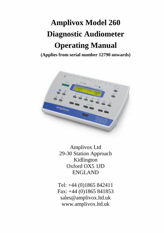
Amplivox Model 260
Diagnostic Audiometer
Operating Manual (Applies from serial number 12790 onwards)
Amplivox Ltd
29-30 Station Approach
Kidlington
Oxford OX5 1JD
ENGLAND
Tel: +44 (0)1865 842411
Fax: +44 (0)1865 841853
www.amplivox.ltd.uk

Contents 1 Introduction 3 1.1 Intended applications 3 1.2 Unpacking 3 1.3 Warranty card (UK customers only) 3 1.4 Standard contents 3 1.5 Optional accessories 4 2 Important Safety Instructions 4 2.1 Precautions 4 2.3 Mains supply operation 5 2.4 Audiometer connections 6 2.5 Data transfer to a printer 6 2.6 Data transfer to a computer 7 2.7 Line in/out connection (audio) 7 3 Using the Audiometer 7 3.1 Switching the audiometer on and off 7 3.2 Testing the patient response switch 8 3.3 Audiometer display 8 3.4 Audiometer controls 8 3.5 Threshold Retention Function 13 3.6 Saving audiograms in internal memory 13 3.7 Loading audiograms from internal memory 14 3.8 Printing audiograms 14 3.9 Data transfer to a NOAH database 14 4 Suggested Sequence of Operation and Test Procedure 15 5 Specification 17 5.1 Output data 17 5.2 Maximum hearing levels provided at each frequency 18 5.3 Physical Data 18 5.4 Equipment classification 18 6 Symbols 19 7 Technical Information 20 8 Routine Maintenance 21 8.1 Audiometer maintenance 21 8.2 Transducer maintenance 21 8.3 Mains adapter maintenance 23 9 Instrument Storage and Transportation 23 10 Calibration and Repair of the Instrument 23 11 Guarantee 24 12 Ordering Consumables and Accessories 25 Appendix 1 - Speech Audiometry 27 Appendix 2 - Free Field Calibration Procedure 33 Appendix 3 - EMC Guidance & Manufacturer’s Declaration 39 Appendix 4 - Use with Non-medical Electrical Equipment 45

Page 2 OM023-4 Amplivox 260 Operating Manual
OM023-4 Amplivox 260 Operating Manual Page 3
1 Introduction Thank you for purchasing an Amplivox audiometer. The Amplivox Model 260 is a diagnostic audiometer that will give many years of reliable service if treated with care. 1.1 Intended applications The Amplivox Model 260 diagnostic audiometer is designed for use by audiologists, general practitioners, hearing aid dispensers and child health professionals. Capable of undertaking both air and bone conduction tests with or without masking, the audiometer has many additional features such as the facility to support speech audiometry from live or recorded sources, the option to select free-field equivalent output from the headphones in speech mode and clinical audiometry tests. 1.2 Unpacking Open the shipping carton and carefully remove all the equipment. Check against the delivery note that all the accessories ordered have been included with your audiometer. If anything is missing, please contact Amplivox Customer Support (+44 1865 842411; [email protected]). If you have purchased from a distributor you should contact them directly. Please retain the shipping carton and packing materials as the audiometer will need calibrating on an annual basis and should be returned to Amplivox in its original shipping carton. 1.3 Warranty card (UK customers only) Please complete the enclosed warranty registration card and return it to Amplivox Ltd to register your purchase. This will help us to deal with your enquires, and we will also be able to send you details of updates to your product and of new products and services. 1.4 Standard contents Amplivox Model 260 Audiometer Audiometric headset Bone conductor headset Patient response switch Mains adaptor, see 2.3 Audiogram cards Operating manual Calibration certificate Carrying case
Page 4 OM023-4 Amplivox 260 Operating Manual
1.5 Optional accessories Masking earpiece Additional audiogram cards Microphone and monitor headset Insert earphones Printers NOAH Audilink Interface Printer cables Data cable for NOAH Audiocups (noise reducing earphone enclosures) 2 Important Safety Instructions
The Amplivox Model 260 instrument must be used only by practitioners qualified to perform audiometric tests. It is intended for use as a screening and diagnostic tool.
2.1 Precautions READ THIS OPERATING MANUAL BEFORE ATTEMPTING TO USE THE INSTRUMENT To comply with the standards IEC 60601-1 for safety and IEC 60601-1-2 for EMC the audiometer is designed to be used only with the medically-approved mains adapter supplied, which is specified as part of the equipment. Do not use any other type of mains adapter with this instrument. Refer to Section 12 for the stock number of the adapter. The audiometer is for indoor use only and should be used only as described in this manual. The transducers supplied with the audiometer are specifically calibrated with it; if these transducers are changed calibration will be required. Do not immerse the unit in any fluids. See section 8 of this manual for the proper cleaning procedure for the instrument and its accessories and the function of single-use parts. Do not use the instrument in an oxygen-rich environment or in the presence of a flammable anaesthetic mixture or other flammable agents. Do not drop or otherwise impact this instrument. If the instrument is dropped or damaged, return it to the manufacturer for repair and/or calibration. Do not use the instrument if any damage is suspected.
OM023-4 Amplivox 260 Operating Manual Page 5
The instrument must be stored and used within the specified temperature, pressure and humidity ranges (see Sections 7 and 9). Do not attempt to open, modify or service the instrument. Return the instrument to the manufacturer or distributor for all repair and servicing requirements. Opening the instrument will void the warranty. 2.2 Electromagnetic compatibility (EMC) considerations Medical electrical equipment needs special precautions regarding EMC and needs to be installed and put into service according to the EMC information in Appendix 3. This provides guidance on the electromagnetic environment in which to operate the instrument. Portable and mobile radio-frequency (RF) communications equipment can affect medical electrical equipment. The instrument should not be used adjacent to or stacked with other equipment; if this is necessary the instrument should be observed to verify normal operation. 2.3 Mains supply operation The audiometer is designed for continuous operation and is powered by a mains adapter which is supplied, and specified as part of the equipment. If a replacement is required, please contact your Amplivox distributor. All other connections must be made before connecting the output lead from the adapter into the POWER input socket on the back of the audiometer. Switch on the mains supply - the indicator on the adapter and the POWER indicator on the audiometer will both illuminate green, showing that the instrument is ready for use. The output from mains adapter is fitted with electronic circuit protection. In case of overload the adapter will shut down and the indicator will be extinguished. When the fault is cleared the adapter will operate as normal. The input to the mains adapter is protected with a non-replaceable fuse. If this fails the adapter will not operate. The mains adapter is the mains disconnect device and therefore the audiometer should be positioned such that easy access to the mains adapter is possible.
Page 6 OM023-4 Amplivox 260 Operating Manual
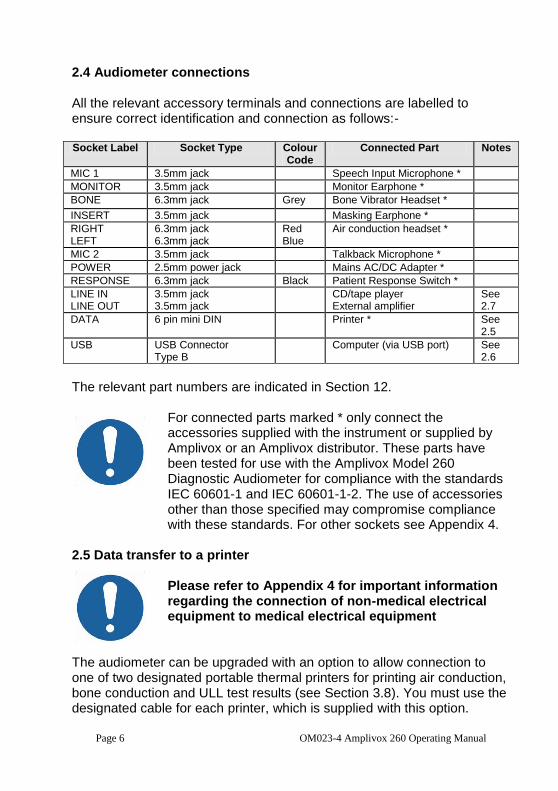
2.4 Audiometer connections All the relevant accessory terminals and connections are labelled to ensure correct identification and connection as follows:- Socket Label Socket Type Colour
Code Connected Part Notes
MIC 1 3.5mm jack Speech Input Microphone *
MONITOR 3.5mm jack Monitor Earphone *
BONE 6.3mm jack Grey Bone Vibrator Headset *
INSERT 3.5mm jack Masking Earphone *
RIGHT LEFT
6.3mm jack 6.3mm jack
Red Blue
Air conduction headset *
MIC 2 3.5mm jack Talkback Microphone *
POWER 2.5mm power jack Mains AC/DC Adapter *
RESPONSE 6.3mm jack Black Patient Response Switch *
LINE IN LINE OUT
3.5mm jack 3.5mm jack
CD/tape player External amplifier
See 2.7
DATA 6 pin mini DIN Printer * See 2.5
USB USB Connector Type B
Computer (via USB port) See 2.6
The relevant part numbers are indicated in Section 12.
For connected parts marked * only connect the accessories supplied with the instrument or supplied by Amplivox or an Amplivox distributor. These parts have been tested for use with the Amplivox Model 260 Diagnostic Audiometer for compliance with the standards IEC 60601-1 and IEC 60601-1-2. The use of accessories other than those specified may compromise compliance with these standards. For other sockets see Appendix 4.
2.5 Data transfer to a printer
Please refer to Appendix 4 for important information regarding the connection of non-medical electrical equipment to medical electrical equipment
The audiometer can be upgraded with an option to allow connection to one of two designated portable thermal printers for printing air conduction, bone conduction and ULL test results (see Section 3.8). You must use the designated cable for each printer, which is supplied with this option.
OM023-4 Amplivox 260 Operating Manual Page 7
Upon receipt of the printer it must be initially charged for a minimum of 15 hours prior to use. 2.6 Data transfer to a computer
Please refer to Appendix 4 for important information regarding the connection of non-medical electrical equipment to medical electrical equipment
The audiometer can be upgraded with an option to allow connection to a computer with the NOAH application for the transfer of air conduction, bone conduction, speech and ULL test results (see Section 3.9). You must use the designated cable which is supplied with this option.
2.7 Line in/out connection (audio)
Please refer to Appendix 4 for important information regarding the connection of non-medical electrical equipment to medical electrical equipment
The Amplivox Model 260 has audio line in/out connections for CD or tape player input (e.g. for recorded speech testing) and amplifier output. Important Note: Line out connections are switched on only when FREFIELD is selected. The following connections apply to both LINE IN and LINE OUT.
Main Body Segment Mid segment End segment
Ground Right Channel Left Channel
For more information on live and recorded speech refer to Appendix 1.
3 Using the Audiometer 3.1 Switching the audiometer on and off Press the ON/OFF key located at the left of the front panel. No warm-up time is required. The display will briefly show the model and the type of headphone currently in use.
Page 8 OM023-4 Amplivox 260 Operating Manual
If a secondary headphone has been enabled (e.g. E-5A) it will then be necessary to select the required headphone as follows:
Either - press YES to confirm the current headphone selection
Or - press NO to toggle to the other option and then YES to confirm the selection
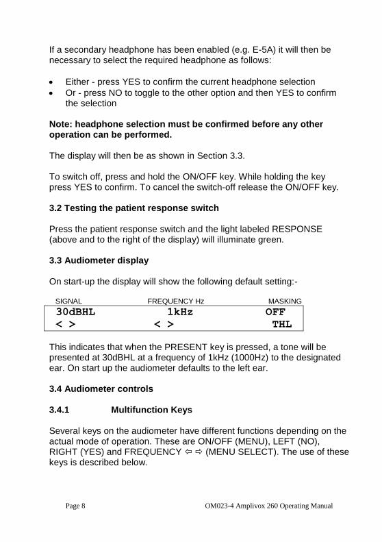
Note: headphone selection must be confirmed before any other operation can be performed. The display will then be as shown in Section 3.3. To switch off, press and hold the ON/OFF key. While holding the key press YES to confirm. To cancel the switch-off release the ON/OFF key. 3.2 Testing the patient response switch Press the patient response switch and the light labeled RESPONSE (above and to the right of the display) will illuminate green. 3.3 Audiometer display On start-up the display will show the following default setting:- SIGNAL FREQUENCY Hz MASKING
30dBHL 1kHz OFF
< > < > THL
This indicates that when the PRESENT key is pressed, a tone will be presented at 30dBHL at a frequency of 1kHz (1000Hz) to the designated ear. On start up the audiometer defaults to the left ear. 3.4 Audiometer controls 3.4.1 Multifunction Keys Several keys on the audiometer have different functions depending on the actual mode of operation. These are ON/OFF (MENU), LEFT (NO), RIGHT (YES) and FREQUENCY (MENU SELECT). The use of these keys is described below.
OM023-4 Amplivox 260 Operating Manual Page 9
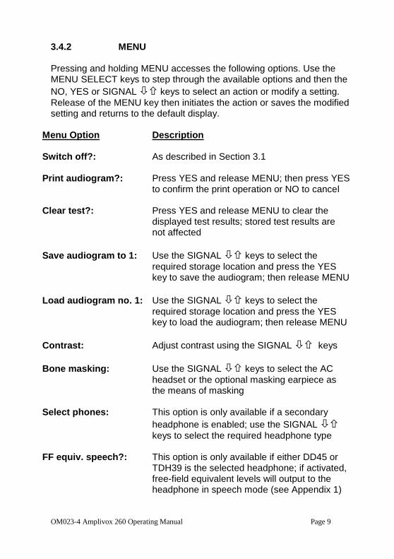
3.4.2 MENU Pressing and holding MENU accesses the following options. Use the MENU SELECT keys to step through the available options and then the
NO, YES or SIGNAL keys to select an action or modify a setting.
Release of the MENU key then initiates the action or saves the modified setting and returns to the default display.
Menu Option Description Switch off?: As described in Section 3.1 Print audiogram?: Press YES and release MENU; then press YES
to confirm the print operation or NO to cancel
Clear test?: Press YES and release MENU to clear the displayed test results; stored test results are not affected
Save audiogram to 1: Use the SIGNAL keys to select the
required storage location and press the YES key to save the audiogram; then release MENU
Load audiogram no. 1: Use the SIGNAL keys to select the
required storage location and press the YES key to load the audiogram; then release MENU
Contrast: Adjust contrast using the SIGNAL keys
Bone masking: Use the SIGNAL keys to select the AC
headset or the optional masking earpiece as the means of masking
Select phones: This option is only available if a secondary
headphone is enabled; use the SIGNAL
keys to select the required headphone type
FF equiv. speech?: This option is only available if either DD45 or TDH39 is the selected headphone; if activated, free-field equivalent levels will output to the headphone in speech mode (see Appendix 1)
Page 10 OM023-4 Amplivox 260 Operating Manual
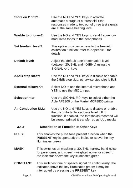
Store on 2 of 3?: Use the NO and YES keys to activate automatic storage of a threshold if the responses made to two out of three test signals are at the same hearing level
Warble to phones?: Use the NO and YES keys to send frequency-
modulated tones to the headphones
Set freefield level?: This option provides access to the freefield calibration function; refer to Appendix 2 for details
Default level: Adjust the default tone presentation level
(between 20dBHL and 40dBHL) using the
SIGNAL keys
2.5dB step size?: Use the NO and YES keys to disable or enable
the 2.5dB step size; otherwise step size is 5dB
External talkover?: Select NO to use the internal microphone and YES to use the MIC 1 input
Select printer: Use the SIGNAL keys to select either the
Able AP1300 or the Martel MCP8830 printer Air Conduction ULL: Use the NO and YES keys to disable or enable
the uncomfortable loudness level (ULL) function; if enabled, the thresholds recorded will be stored, printed & transferred as ULL results
3.4.3 Description of Function of Other Keys
PULSE This enables the pulse tone present function when the PRESENT key is operated; the indicator above the key illuminates green
MASK This switches on masking at 30dBHL; narrow band noise
for pure tones, and speech-weighted noise for speech; the indicator above the key illuminates green
CONSTANT This switches tone or speech signal on continuously; the
indicator above the key illuminates green; it may be interrupted by pressing the PRESENT key
OM023-4 Amplivox 260 Operating Manual Page 11
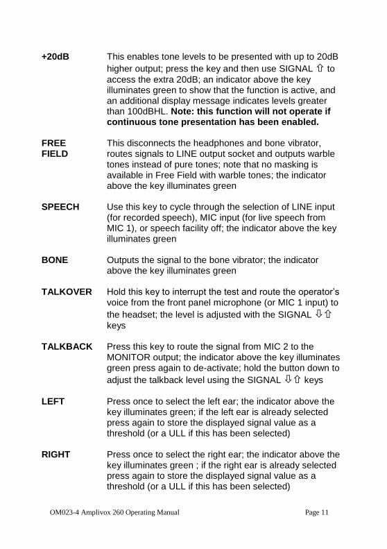
+20dB This enables tone levels to be presented with up to 20dB
higher output; press the key and then use SIGNAL to
access the extra 20dB; an indicator above the key illuminates green to show that the function is active, and an additional display message indicates levels greater than 100dBHL. Note: this function will not operate if continuous tone presentation has been enabled.
FREE This disconnects the headphones and bone vibrator, FIELD routes signals to LINE output socket and outputs warble
tones instead of pure tones; note that no masking is available in Free Field with warble tones; the indicator above the key illuminates green
SPEECH Use this key to cycle through the selection of LINE input
(for recorded speech), MIC input (for live speech from MIC 1), or speech facility off; the indicator above the key illuminates green
BONE Outputs the signal to the bone vibrator; the indicator
above the key illuminates green TALKOVER Hold this key to interrupt the test and route the operator’s
voice from the front panel microphone (or MIC 1 input) to
the headset; the level is adjusted with the SIGNAL
keys TALKBACK Press this key to route the signal from MIC 2 to the
MONITOR output; the indicator above the key illuminates green press again to de-activate; hold the button down to
adjust the talkback level using the SIGNAL keys
LEFT Press once to select the left ear; the indicator above the key illuminates green; if the left ear is already selected press again to store the displayed signal value as a threshold (or a ULL if this has been selected)
RIGHT Press once to select the right ear; the indicator above the
key illuminates green ; if the right ear is already selected press again to store the displayed signal value as a threshold (or a ULL if this has been selected)
Page 12 OM023-4 Amplivox 260 Operating Manual
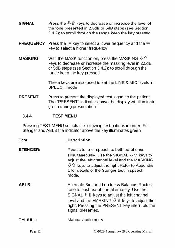
SIGNAL Press the keys to decrease or increase the level of
the tone presented in 2.5dB or 5dB steps (see Section 3.4.2); to scroll through the range keep the key pressed
FREQUENCY Press the key to select a lower frequency and the
key to select a higher frequency
MASKING With the MASK function on, press the MASKING
keys to decrease or increase the masking level in 2.5dB or 5dB steps (see Section 3.4.2); to scroll through the range keep the key pressed
These keys are also used to set the LINE & MIC levels in
SPEECH mode
PRESENT Press to present the displayed test signal to the patient. The “PRESENT” indicator above the display will illuminate green during presentation
3.4.4 TEST MENU Pressing TEST MENU selects the following test options in order. For Stenger and ABLB the indicator above the key illuminates green.
Test Description
STENGER: Routes tone or speech to both earphones
simultaneously. Use the SIGNAL keys to
adjust the left channel level and the MASKING
keys to adjust the right Refer to Appendix
1 for details of the Stenger test in speech mode.
ABLB: Alternate Binaural Loudness Balance: Routes
tone to each earphone alternately. Use the
SIGNAL keys to adjust the left channel
level and the MASKING keys to adjust the
right. Pressing the PRESENT key interrupts the signal presented.
THL/ULL: Manual audiometry
OM023-4 Amplivox 260 Operating Manual Page 13
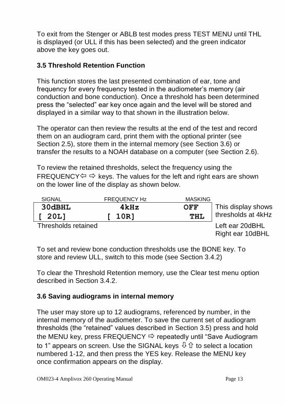
To exit from the Stenger or ABLB test modes press TEST MENU until THL is displayed (or ULL if this has been selected) and the green indicator above the key goes out. 3.5 Threshold Retention Function This function stores the last presented combination of ear, tone and frequency for every frequency tested in the audiometer’s memory (air conduction and bone conduction). Once a threshold has been determined press the “selected” ear key once again and the level will be stored and displayed in a similar way to that shown in the illustration below. The operator can then review the results at the end of the test and record them on an audiogram card, print them with the optional printer (see Section 2.5), store them in the internal memory (see Section 3.6) or transfer the results to a NOAH database on a computer (see Section 2.6). To review the retained thresholds, select the frequency using the
FREQUENCY keys. The values for the left and right ears are shown
on the lower line of the display as shown below. SIGNAL FREQUENCY Hz MASKING
30dBHL 4kHz OFF
[ 20L] [ 10R] THL
This display shows thresholds at 4kHz
Thresholds retained Left ear 20dBHL Right ear 10dBHL
To set and review bone conduction thresholds use the BONE key. To store and review ULL, switch to this mode (see Section 3.4.2) To clear the Threshold Retention memory, use the Clear test menu option described in Section 3.4.2. 3.6 Saving audiograms in internal memory The user may store up to 12 audiograms, referenced by number, in the internal memory of the audiometer. To save the current set of audiogram thresholds (the “retained” values described in Section 3.5) press and hold
the MENU key, press FREQUENCY repeatedly until “Save Audiogram
to 1” appears on screen. Use the SIGNAL keys to select a location
numbered 1-12, and then press the YES key. Release the MENU key once confirmation appears on the display.
Page 14 OM023-4 Amplivox 260 Operating Manual
Note that the Save process will overwrite any records that exist in the selected memory location. 3.7 Loading audiograms from internal memory Press and hold the MENU key, press FREQUENCY repeatedly until
“Load Audiogram no. 1” appears on screen. Use the SIGNAL keys to
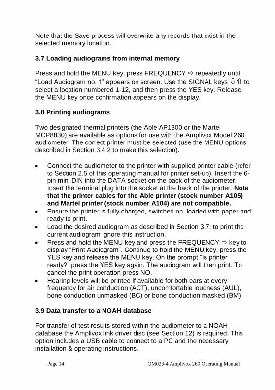
select a location numbered 1-12, and then press the YES key. Release the MENU key once confirmation appears on the display. 3.8 Printing audiograms Two designated thermal printers (the Able AP1300 or the Martel MCP8830) are available as options for use with the Amplivox Model 260 audiometer. The correct printer must be selected (use the MENU options described in Section 3.4.2 to make this selection).
Connect the audiometer to the printer with supplied printer cable (refer to Section 2.5 of this operating manual for printer set-up). Insert the 6-pin mini DIN into the DATA socket on the back of the audiometer. Insert the terminal plug into the socket at the back of the printer. Note that the printer cables for the Able printer (stock number A105) and Martel printer (stock number A104) are not compatible.
Ensure the printer is fully charged, switched on, loaded with paper and ready to print.
Load the desired audiogram as described in Section 3.7; to print the current audiogram ignore this instruction.
Press and hold the MENU key and press the FREQUENCY key to display “Print Audiogram”. Continue to hold the MENU key, press the YES key and release the MENU key. On the prompt “Is printer ready?” press the YES key again. The audiogram will then print. To cancel the print operation press NO.
Hearing levels will be printed if available for both ears at every frequency for air conduction (ACT), uncomfortable loudness (AUL), bone conduction unmasked (BC) or bone conduction masked (BM)
3.9 Data transfer to a NOAH database For transfer of test results stored within the audiometer to a NOAH database the Amplivox link driver disc (see Section 12) is required. This option includes a USB cable to connect to a PC and the necessary installation & operating instructions.
OM023-4 Amplivox 260 Operating Manual Page 15
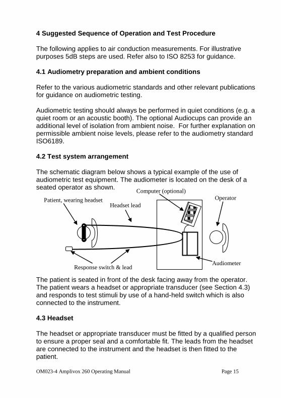
4 Suggested Sequence of Operation and Test Procedure The following applies to air conduction measurements. For illustrative purposes 5dB steps are used. Refer also to ISO 8253 for guidance. 4.1 Audiometry preparation and ambient conditions Refer to the various audiometric standards and other relevant publications for guidance on audiometric testing. Audiometric testing should always be performed in quiet conditions (e.g. a quiet room or an acoustic booth). The optional Audiocups can provide an additional level of isolation from ambient noise. For further explanation on permissible ambient noise levels, please refer to the audiometry standard ISO6189. 4.2 Test system arrangement The schematic diagram below shows a typical example of the use of audiometric test equipment. The audiometer is located on the desk of a seated operator as shown.
The patient is seated in front of the desk facing away from the operator. The patient wears a headset or appropriate transducer (see Section 4.3) and responds to test stimuli by use of a hand-held switch which is also connected to the instrument. 4.3 Headset The headset or appropriate transducer must be fitted by a qualified person to ensure a proper seal and a comfortable fit. The leads from the headset are connected to the instrument and the headset is then fitted to the patient.
Operator
Audiometer
Computer (optional)
Patient, wearing headset
Headset lead
Response switch & lead
Page 16 OM023-4 Amplivox 260 Operating Manual
4.4 Patient instructions
The patient should be given the following instructions using the TALKOVER function:
“As soon as you hear the tone, press the response switch. When you no longer hear the tone release the response switch”
4.5 Pre-test (1) Switch the audiometer on (2) Perform a listening check (3) Decide whether to use the Threshold Retention Function, the Store on
2 of 3 option, or an audiogram card to record the thresholds (4) Prepare the test environment & patient (see Sections 4.1 to 4.4) (5) Select the better hearing ear (according to the patient) by pressing
either the LEFT or RIGHT key 4.6 Test (6) Present the first test tone at 30dB at 1kHz (7) If the patient responds, reduce the signal level in 10dB steps until they
no longer respond; then increase the signal level in 5dB steps until the patient responds
(8) If the patient fails to hear the first tone, increase the signal level in 5dB steps until they do respond and then continue with step 10
(9) Repeat the test by reducing the signal level in 10dB steps until the patient no longer responds; then increase the signal level in 5dB steps until they do respond and note this level
(10) If Store on 2 of 3 is selected, go to step 13 (11) Repeat step 10 until the patient responds three out of a maximum of
five times at the same signal level, indicating the patient’s hearing threshold level for that frequency; mark the threshold on an audiogram card or press the “selected” ear key once to activate the Threshold Retention Function which then displays the threshold on screen
(12) If Store on 2 of 3 is selected, repeat step 10 until the patient has responded 2 out of a maximum of 3 times at the same signal level; this will automatically display the threshold on the screen
(13) Proceed to the next test frequency and repeat steps 7 to 13 (14) Repeat steps 7 to 14 for the other ear
OM023-4 Amplivox 260 Operating Manual Page 17
4.7 Post-test (15) Use the Threshold Retention Function to review the results (See 3.5) (16) If required do one or more of the following: Record the results on an audiogram card, or Save the results to the internal memory (Section 3.6), or Print the results (Section 3.8), or Transfer the results to a computer (Section 3.9) To clear the Threshold Retention memory, use the Clear test menu option described in Section 3.4.2. 5 Specification 5.1 Output data Outputs: Left earphone, Right earphone, Bone (L&R)
Insert masking and Freefield Frequency range (Hz): Air: 125-8KHz Bone: 250Hz-8KHz Frequency accuracy: <1% Distortion: <2% Output level range (AC): -10dBHL to 120dBHL maximum Output level range (BC): -10dBHL to 70dBHL maximum Output level range (FF): Up to 90dB Insert masking output: 90dBHL max (250-4KHz) Output level accuracy: Within 3dB Output level step size: 2.5 or 5dB Output transducer (AC): DD45 earphones (supplied) E-5A insert earphones (option) Output transducer (BC): B-71 bone vibrator (supplied) Tone present: Single, pulsed, warble or continuous Masking: Narrowband (tone) or speech-weighted Clinical tests: Stenger & ABLB (Fowler) Communication: Integral talk over and talk back facility Recorded speech: Tape or CD input Live speech: 1 x microphone input Monitoring indicator: VU - (to IEC 60268-17; ANSI S3.6:2004) NOAH interface: Transfer of AC, BC & ULL test results
Page 18 OM023-4 Amplivox 260 Operating Manual
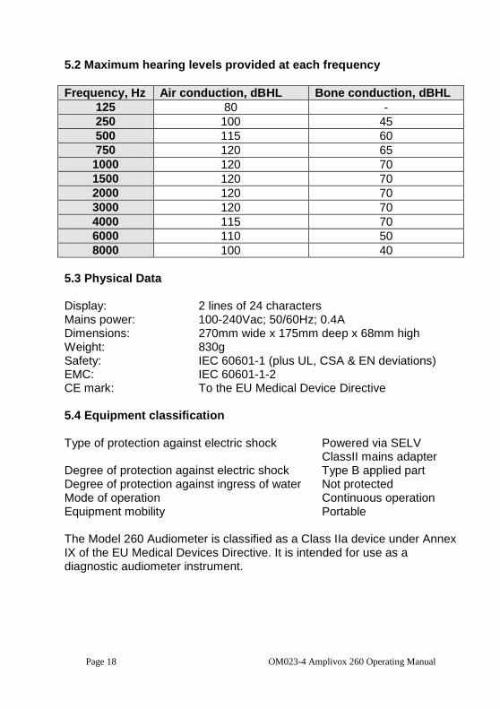
5.2 Maximum hearing levels provided at each frequency
Frequency, Hz Air conduction, dBHL Bone conduction, dBHL
125 80 -
250 100 45
500 115 60
750 120 65
1000 120 70
1500 120 70
2000 120 70
3000 120 70
4000 115 70
6000 110 50
8000 100 40
5.3 Physical Data Display: 2 lines of 24 characters Mains power: 100-240Vac; 50/60Hz; 0.4A Dimensions: 270mm wide x 175mm deep x 68mm high Weight: 830g Safety: IEC 60601-1 (plus UL, CSA & EN deviations) EMC: IEC 60601-1-2 CE mark: To the EU Medical Device Directive 5.4 Equipment classification Type of protection against electric shock Powered via SELV
ClassII mains adapter Degree of protection against electric shock Type B applied part Degree of protection against ingress of water Not protected Mode of operation Continuous operation Equipment mobility Portable The Model 260 Audiometer is classified as a Class IIa device under Annex IX of the EU Medical Devices Directive. It is intended for use as a diagnostic audiometer instrument.
OM023-4 Amplivox 260 Operating Manual Page 19
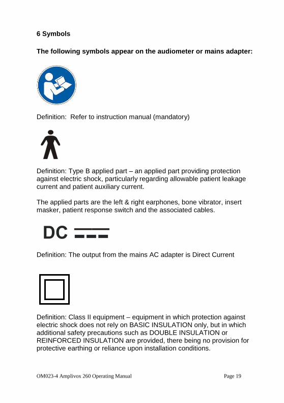
6 Symbols
The following symbols appear on the audiometer or mains adapter:
Definition: Refer to instruction manual (mandatory)
Definition: Type B applied part – an applied part providing protection against electric shock, particularly regarding allowable patient leakage current and patient auxiliary current. The applied parts are the left & right earphones, bone vibrator, insert masker, patient response switch and the associated cables.
Definition: The output from the mains AC adapter is Direct Current Definition: Class II equipment – equipment in which protection against electric shock does not rely on BASIC INSULATION only, but in which additional safety precautions such as DOUBLE INSULATION or REINFORCED INSULATION are provided, there being no provision for protective earthing or reliance upon installation conditions.
Page 20 OM023-4 Amplivox 260 Operating Manual
7 Technical Information Audiometer Audiometer type: Type 2 (IEC 60645-1:2001)
Type B-E (IEC 60645-2:1993) Type 3BE (ANSI S3.6:2004)
Frequency Modulation Carrier frequencies: 125Hz to 8kHz as per pure tones Modulation waveform: Sinusoidal Rising and falling symmetry: Symmetrical on linear frequency scale Modulating frequency: 15.625Hz Frequency deviation: +/-10% Speech Channel Frequency response: +/-3dB, 100Hz to 10kHz at output
terminals (e.g. headphone or line out) Voltage requirement at 0dB input level setting to zero meter: 1.20Vrms at 1kHz Output level: 90dBSPL at 1kHz for attenuator setting of
70dBHL with level meter at 0dB Masking Sounds Masking sounds available: Narrow bands at test frequencies and
Speech weighted noise Narrow-band noise bandwidth: Meets IEC 60645-1; ANSI S3.6 Speech noise bandwidth: Meets IEC 60645-2; ANSI S3.6 Reference levels: Refer to ISO 389-4 Insert Masking Earpiece Calibration method: With 2cc coupler compliant with IEC 126 Transducers Types and reference levels: DD45: ISO 389-1, Table 2
E-5A: ISO 389-2, Table 1 B-71: ISO 389-3, Table 1
Static headband force: Headphones: 4.5N Bone vibrator: 5.4N Bone vibrator calibrated: For mastoid placement &
unoccluded test ear Sound attenuation characteristics: ISO8253-1, Table 3 Airborne sound from bone vibrator: See Br. J. Audiol. 1980, P73-75
OM023-4 Amplivox 260 Operating Manual Page 21
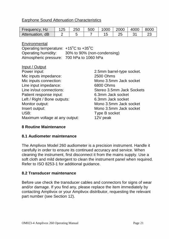
Earphone Sound Attenuation Characteristics
Frequency, Hz 125 250 500 1000 2000 4000 8000
Attenuation, dB 2 5 7 15 25 31 23
Environmental Operating temperature: +15
oC to +35
oC
Operating humidity: 30% to 90% (non-condensing) Atmospheric pressure: 700 hPa to 1060 hPa Input / Output Power input: 2.5mm barrel-type socket. Mic inputs impedance: 2500 Ohms Mic inputs connection: Mono 3.5mm Jack socket Line input impedance: 6800 Ohms Line in/out connections: Stereo 3.5mm Jack Sockets Patient response input: 6.3mm Jack socket Left / Right / Bone outputs: 6.3mm Jack socket Monitor output: Mono 3.5mm Jack socket Insert output: Mono 3.5mm Jack socket USB: Type B socket Maximum voltage at any output: 12V peak 8 Routine Maintenance 8.1 Audiometer maintenance The Amplivox Model 260 audiometer is a precision instrument. Handle it carefully in order to ensure its continued accuracy and service. When cleaning the instrument, first disconnect it from the mains supply. Use a soft cloth and mild detergent to clean the instrument panel when required. Refer to ISO 8253-1 for additional guidance. 8.2 Transducer maintenance Before use check the transducer cables and connectors for signs of wear and/or damage. If you find any, please replace the item immediately by contacting Amplivox or your Amplivox distributor, requesting the relevant part number (see Section 12).
Page 22 OM023-4 Amplivox 260 Operating Manual
Handle the audiometric headset, bone vibrator headset and other accessories with care. For parts that are in direct contact with the patient it is recommended that replacement parts are used or the parts are subjected to a standard disinfecting procedure between patients. This includes physically cleaning and use of a recognised disinfectant. The specific manufacturer's instructions should be followed for use of this disinfecting agent to provide an appropriate level of cleanliness.
During the cleaning process do not allow moisture to enter the earphone, insert masker, monitor or microphone grills etc. For specific accessories refer to the sections below.
Earphones Clean the ear cushions (including those on the Audiocups, if used) with a recognised disinfectant, e.g. a “Mediswab”. Insert Masker Never insert or in any way use the insert masker without using a new, clean and fault-free test tip. This part is for single use only - that is, each test tip is intended to be used once only for a single ear for a single patient. Do not reuse test tips as this will pose the risk of ear-to-ear or patient-to-patient cross-infection. Insert Earphones The disposable foam eartips supplied with the optional EarTone5A insert transducers are for single use only - that is, each eartip is intended to be used once only for a single ear for a single patient. Do not reuse eartips as this will pose the risk of ear-to-ear or patient-to-patient cross-infection. Further guidance is provided below:
Ensure that the black tubing protruding the foam eartip is not applied to the patient; this must be attached to the sound tube of the insert transducer
Roll the foam eartip into the smallest possible diameter
Insert the eartip into the ear canal of the patient
OM023-4 Amplivox 260 Operating Manual Page 23
Hold the eartip until it has expanded and a seal is achieved
After testing the patient the foam eartip including the black tubing must be detached from the sound tube
The insert transducer should be examined prior to attaching a new foam eartip
8.3 Mains adapter maintenance Before use, check the mains AC adapter for signs of wear and/or damage. If you find any replace the adapter immediately by contacting Amplivox or your Amplivox distributor. Refer to Section 12 for approved part numbers
DO NOT USE ANY OTHER TYPE OF MAINS ADAPTER WITH THIS INSTRUMENT. See Section 2.3.
9 Instrument Storage and Transportation This instrument can be stored or transported with the following environmental parameters: Temperature: -20
oC to +70
oC
Humidity: 10% to 90% (non-condensing) Atmospheric Pressure: 500 hPa to 1060 hPa 10 Calibration and Repair of the Instrument Amplivox recommend that this audiometer should be calibrated on an annual basis. Please contact Amplivox or the designated distributor for
details of calibration services. Refer to ISO 8253-1 for additional guidance.
The instrument should be returned to the manufacturer for service & repair. There are no user-serviceable parts within it.
When packing the instrument for shipping, please use the original shipping carton and packing materials. Please also ensure that the headset leads are not wrapped around the headband of the headset.
Page 24 OM023-4 Amplivox 260 Operating Manual
11 Guarantee All Amplivox instruments are guaranteed against faulty materials and manufacture. The instrument will be repaired free of charge for a period of one year from the date of despatch if returned, carriage paid, to the Amplivox service department. Return carriage is free of charge for customers in the UK and chargeable for overseas customers. Important Note: The following exceptions apply: Earphones, bone vibrator and other transducers may go out of calibration due to rough handling or impact (dropping). The life of the leads is also dependent upon conditions of use. These parts are only guaranteed against faulty materials or manufacture.
OM023-4 Amplivox 260 Operating Manual Page 25
12 Ordering Consumables and Accessories To order consumables, additional accessories and to replace detachable parts that have been damaged, please contact Amplivox for current prices and delivery charges. The items available are listed below: Stock No. Description A022 Audiocups (noise reducing earphone enclosures) AC1042 Audiocup ear cushion AC1047 Audiocup headband AC1048 Audiocup headband cover A023 Headband (standard headphone) A026 Earphone cushion A032 Earphones DD45 * A030 Headset lead A080 Bone vibrator B71 * A025 Bone vibrator headband A029 Bone vibrator lead C15 Masking earpiece * C13 Masking earpiece ear tip C12 Masking earpiece ear hanger C14 Masking earpiece lead A200 Insert earphones * B129 Carrying case A091-7 Approved mains adapter (within EU) A085 Patient response switch A051 Audiogram cards (pack of 50) A051 Audiogram cards (pack of 50) MAN260 Amplivox Model 260 operating manual (OM023) C17 Microphone and monitor headset NOAH01 Amplivox NOAH Audilink Interface (includes USB cable) F07 USB Cable, 1.8m A109 Free field cable (connects to Line Out) A091 Printer Martel MCP8830 PT01 Printer Able AP1300
Page 26 OM023-4 Amplivox 260 Operating Manual
A104 6 pin printer cable for audiometer to Martel MCP8830 A105 6 pin printer cable for audiometer to Able AP1300 C01 Thermal Printer paper for Martel MCP8830 C0103 Thermal Printer paper for Able AP1300
Accessories marked * require calibration with the specific audiometer to be used. Do not attempt to use these accessories until the audiometer has been calibrated to match their characteristics.
Shipping documentation will reference the stock number quoted above, and images of the parts alongside the relevant stock number are available on the Amplivox/Amplivox website (www.amplivox.ltd.uk). The required fitting instructions are supplied with each part.
OM023-4 Amplivox 260 Operating Manual Page 27
Appendix 1 - Speech Audiometry The Amplivox Model 260 audiometer may be used in the following speech modes of operation. However users should be aware that there is a growing body of professional opinion that Live Voice speech audiometry is generally not recommended. For recorded speech audiometry, only material with a stated relationship with the calibration signal should be used. Use the SPEECH key to switches between MIC1 (live) or LINE (recorded) inputs. Headphone and Free Field Testing Note that the line outputs from the instrument (used for free-field testing) are only active when FREEFIELD is selected.
If headphone testing is being performed, it is recommended that any attached amplifier should be switched off
If Free Field testing is being performed, this option must always be selected on the audiometer; this disconnects headphones, bone vibrator and masking insert outputs, and ensures that the correct calibrated output levels are achieved
If free-field equivalent output is required from the headphones in Speech mode this option should be selected (see Section 3.4.2)
Operator Monitoring Where an acoustic booth/room is used, a patient microphone is connected to the MIC2 input, while the operator headset/earpiece is connected to the MONITOR output. The operator listening levels may be adjusted as follows:
The level of the speech signal is controlled by the FREQUENCY keys, giving 2dB steps
The level of the patient's responses is controlled by using the SIGNAL
keys while pressing and holding TALKBACK; press the
TALKBACK key to toggle talkback on and off Test Modes in Speech Audiometry Initially in speech mode either ear may be selected, with the output level
controlled by the SIGNAL keys in 2.5dB or 5dB steps. Pressing
TEST MENU routes the speech to both ears (Stenger test with speech),
with the left output level controlled by the SIGNAL keys and the right
output level controlled by the MASKING keys. Pressing TEST MENU
again returns to the original speech mode.
Page 28 OM023-4 Amplivox 260 Operating Manual
A1.1 Live Voice Speech Audiometry to Headphones A1.1.1 Set Up: a) Connect a microphone to the MIC1 input on the audiometer b) Press SPEECH repeatedly to ensure that ‘MIC’ is displayed in capitals
at the bottom left of the display (indicating that the external microphone is selected)
c) The microphone is initially routed to the left earphone. To select the right earphone press RIGHT
d) The input signal level is adjusted in 1dB steps by use of the MASKING
keys
e) Input signal adjustment should be made to adjust for the operator’s voice to peak at the 0dB point on the LEVEL dB bar graph; the earphone output will then be 89dBSPL for a SIGNAL setting of 70 dBHL and 1kHz puretone into an IEC 318 ear simulator
f) The output level is controlled by the SIGNAL keys in 2.5dB or
5dB steps (depending on settings - see Section 3.4.2) g) Sound from MIC1 is continually routed to the patient - to interrupt this,
press and hold the PRESENT key; if a constant presentation to the patient is not desired, press the CONSTANT key (the LED will extinguish) and use the PRESENT key while presenting the test material
A1.1.2 Procedure: The operator may now read the required word list to the subject and record the responses; the patient may respond either by (a) repeating the spoken material or (b) writing the words. If the response is spoken, the operator should use the TALKBACK key to hear this response (see operator monitoring above).
A1.2 Live Voice Speech Audiometry with Contralateral Masking A1.2.1 Set Up - as described in A1.1.1 then: a) Select MASK b) INT is now displayed indicating that internal masking is selected
(Note: External masking is not available when MIC is selected) c) Speech-weighted masking is now routed to the opposite earphone to
that selected
OM023-4 Amplivox 260 Operating Manual Page 29
d) The MASKING keys change the masking level in 2.5dB or 5dB
steps (depending on settings - see Section 3.4.2) e) If required, readjustment of the input signal level can be accessed by
pressing the MASK key to temporarily deselect the masking function; proceed as in A1.1.1d) and when adjustment has been completed press the MASK key to activate the masking noise
A1.2.2 Procedure: As described in A1.1.2 but adjusting the masking level as required using
the MASKING keys.
A1.3 Recorded Speech Audiometry to Headphones A1.3.1 Set Up: a) Connect a CD, tape player, or other sound source to the LINE IN jack
socket; refer to Section 2.7 of this operating manual b) Press SPEECH repeatedly to ensure that ‘LINE’ is displayed in
capitals at the bottom left of the display (indicating that the input from LINE IN is selected)
c) The line input is initially routed to the left earphone. To select the right earphone press RIGHT
d) The input signal level is adjusted in 1dB steps by use of the MASKING
keys
e) Play the 1kHz calibration tone on the recorded material and adjust the input signal such that the LEVEL dB bar graph reads 0dB; the headphone output measured in an IEC 318 ear simulator will now be 89dBSPL for a setting of 70 dBHL
h) The output level is controlled by the SIGNAL keys in 2.5dB or
5dB steps (depending on settings - see Section 3.4.2) i) Sound from LINE IN is continually routed to the patient - to interrupt
this, press and hold the PRESENT key; if a constant presentation to the patient is not desired, press the CONSTANT key (the LED will extinguish) and use the PRESENT key while presenting the test material
A1.3.2 Procedure: As described in A1.1.2 except that the operator plays the recorded material to the subject.
Page 30 OM023-4 Amplivox 260 Operating Manual
A1.4 Recorded Speech Audiometry to Headphones with Contralateral Masking
A1.4.1 Set Up - as described in A1.3.1 then: a) Select MASK b) Switch between INT (internal) and EXT (external) masking source by
pressing the MASK key until the required option is displayed in capitals; INT will be speech-weighted noise and EXT will be the competing noise from the signal source
c) The masking noise is now routed to the opposite earphone to that selected
d) The MASKING keys changes the masking level in 2.5dB or 5dB
steps (depending on settings - see Section 3.4.2) e) If required, readjustment of the input signal level can be accessed by
pressing the MASK key to temporarily deselect the masking function; proceed as in A1.1.1d) and when adjustment has been completed press the MASK key to activate the appropriate masking noise
A1.4.2 Procedure: As described in A1.3.2 but adjusting the masking level as required using
the MASKING keys.
IMPORTANT NOTES – FREE FIELD MODES
For the following Free Field modes of operation it is essential for the Free
Field calibration procedure described in Appendix 2 of this operating manual to have been performed. This aspect may also be subject to local
requirements or legislation. A1.5 Free Field Live Voice Speech Audiometry A1.5.1 Set Up: a) Connect an external amplifier/speaker to the LINE OUT jack socket;
refer to Section 2.7 of this operating manual b) Connect a microphone to the MIC1 input on the audiometer c) Press SPEECH repeatedly to ensure that ‘MIC’ is displayed in capitals
at the bottom left of the display (indicating that the external microphone is selected)
d) Press the FREEFIELD key
OM023-4 Amplivox 260 Operating Manual Page 31
e) The external microphone is now routed to the external amplifier and speaker; use LEFT and RIGHT to select the required amplifier channel
f) Continue from Section A1.1.1d) to Section A1.1.1g) above A1.5.2 Procedure: As described in A1.1.2. A1.6 Free Field Recorded Speech Audiometry A1.6.1 Set Up: a) Connect an external amplifier/speaker to the LINE OUT jack socket,
and a CD, tape player, or other sound source to the LINE IN jack socket; refer to Section 2.7 of this operating manual
b) Press SPEECH repeatedly to ensure that ‘LINE’ is displayed in capitals at the bottom left of the display (indicating that the input from LINE IN is selected)
c) Press the FREE FIELD key d) The line input is now routed to the external amplifier and speaker; use
LEFT and RIGHT to select the required amplifier channel e) Play the 1kHz calibration tone on the recorded material and follow the
calibration procedure in Appendix 2 f) The input signal level is adjusted in 1dB steps by use of the MASKING
keys
g) Adjust the input signal such that the LEVEL dB bar graph reads 0dB A1.6.2 Procedure: As described in A1.3.2 A1.7 Free Field Recorded Speech Audiometry With Competing
Noise (Audiometer-Generated) A1.7.1 Set Up: - as described in A1.6.1 then: a) Press the MASK key b) Ensure that INT is displayed in capitals indicating that the audiometer-
generated noise is selected; if necessary press the MASK key until INT is displayed in capitals
c) Speech-weighted noise is routed to the competing LINE OUT channel
Page 32 OM023-4 Amplivox 260 Operating Manual
d) The level of competing noise is adjusted using the MASKING
keys in 2.5dB or 5dB steps (depending on settings - see Section 3.4.2)
A1.7.2 Procedure: As described in A1.3.2 but adjusting the competing noise level as required. A1.8 Free Field Recorded Speech Audiometry With Competing
Noise (Recorded) A1.8.1 Set Up: as described in A1.7.1 except: a) Ensure that EXT is displayed in capitals indicating that competing
noise from the signal source is selected; if necessary press the MASK key until EXT is displayed in capitals
b) Competing noise from the signal source is routed to the competing LINE OUT channel
c) Use the SIGNAL keys to adjust the signal channel and the
MASKING keys to adjust the noise channel
A1.8.2 Procedure: As described in A1.3.2 but adjusting the competing noise level as required.
OM023-4 Amplivox 260 Operating Manual Page 33
Appendix 2 - Free Field Calibration Procedure A2.1 Assurance of Calibration The following is a brief description of the equipment and procedures to be used with the Amplivox Model 260 audiometer as a means of performing free-field calibration. However it must be emphasised that it is the responsibility of the equipment operator to ensure that correct free-field calibration has been achieved, and it is recommended that the standards for free-field & speech testing & calibration (e.g. ISO 8253-3 & ISO 389-7) and other appropriate reference works are consulted. It is assumed that the room, speakers and listening position have been set up in conformance with the relevant standards and that the required calibration equipment, operating procedures and trained technical staff are available to perform this operation. Once calibrated, items should not be moved, removed, or added to the room without re-calibration. A2.2 External Amplifier and Loudspeaker The following external equipment is specified for use of the Amplivox Model 260 audiometer in free-field modes of operation:
Amplifier: Interacoustics AP70
Loudspeaker: Interacoustics ALS7 A2.3 Calibration Overview The following calibration should be performed before any free-field tests are performed, and repeated if any changes to equipment positions or settings are made, or if there are other changes to the room (e.g. furniture moved). Place the speaker(s) in the desired position(s), at least 1.5 meters from the subject’s listening position. Refer to the specification for the test to be performed for correct loudspeaker and subject alignment(s). For calibration, the measuring microphone of a sound level meter (SLM) is placed at the reference point (the point that the subject’s head will be located). The procedures outlined below cover calibration for both speech and warble tone modes of audiometry. If both modes are to be use then
Page 34 OM023-4 Amplivox 260 Operating Manual
speech calibration must be carried out first. If only warble mode is to be used then only the warble part of the calibration procedure may be carried out. However, if speech mode is required later (and a speech calibration is performed) this will invalidate any previous warble calibration which would then need to be repeated. If warble tones are to be used as a means of equalising the frequency response in the speech calibration (see Section A2.4.1.1) then this will invalidate any previous warble calibration which would then need to be repeated when warble tone testing is required. A2.4 Free-field Speech Calibration This is carried out in two stages:
1) the speech channel, which contains two elements:
an optional equalisation phase
a level-setting phase
2) the competing noise channel, which may be omitted if competing noise is not required
A2.4.1 Calibrating the Speech Channel A2.4.1.1 Equalisation (Optional) To perform equalisation, connect an external speech source to the audiometer (e.g. CD or tape player). From the default (switch-on) condition of the audiometer select SPEECH and FREEFIELD and then play the test signal from the speech recording. This should either be:
pink noise used with a third-octave spectrum analyser and the SLM
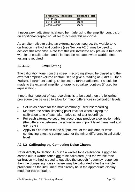
third-octave noise bands used with the SLM Use the SIGNAL control to set the output to 70dBHL, and adjust the external amplifier to give a reading of 90dBSPL as measured by the SLM at the reference point. The response should then be checked to be within the following limits (IEC 60645-2:1993 Section 10.1):
OM023-4 Amplivox 260 Operating Manual Page 35
Frequency Range (Hz) Tolerance (dB)
125 to 250 +0/-10
250 to 4000 +3/-3
4000 to 6300 +5/-5
If necessary, adjustments should be made using the amplifier controls or an additional graphic equalizer to achieve this response. As an alternative to using an external speech source, the warble-tone calibration method and controls (see Section A2.5) may be used to achieve this response. Note that this will invalidate any previous free-field warble tone calibration, and this must be repeated when warble tone testing is required. A2.4.1.2 Level Setting The calibration tone from the speech recording should be played and the external amplifier volume control used to give a reading of 90dBSPL for a 70dBHL instrument setting. Once set, no further adjustment should be made to the external amplifier or graphic equalizer controls (if used for equalisation). If more than one set of test recordings is to be used then the following procedure can be used to allow for minor differences in calibration levels:
Set up as above for the most commonly used test recording
Measure the actual listening point level for when playing the calibration tone of each alternative set of test recordings
For each alternative set of test recordings produce a correction table (the difference between the actual listening point level measured and 90dBSPL)
Apply this correction to the output level of the audiometer while conducting a test to compensate for the minor difference in calibration level
A2.4.2 Calibrating the Competing Noise Channel Refer directly to Section A2.5.2 if a warble tone calibration is not to be carried out. If warble tones are to be calibrated (or if the warble tone calibration method is used to equalise the speech frequency response) then the competing noise channel may be calibrated after the warble procedure as the instrument will already be in the appropriate display mode for this operation.
Page 36 OM023-4 Amplivox 260 Operating Manual
A2.5 Free-field Warble Tones Calibration A2.5.1 Entering Free Field Calibration Mode
Press and hold the MENU key and then use the MENU SELECT keys to move through the menu items and access ‘Set freefield level?’
Press the YES key, release the MENU key and you are now presented with the freefield calibration screen for Warble tones
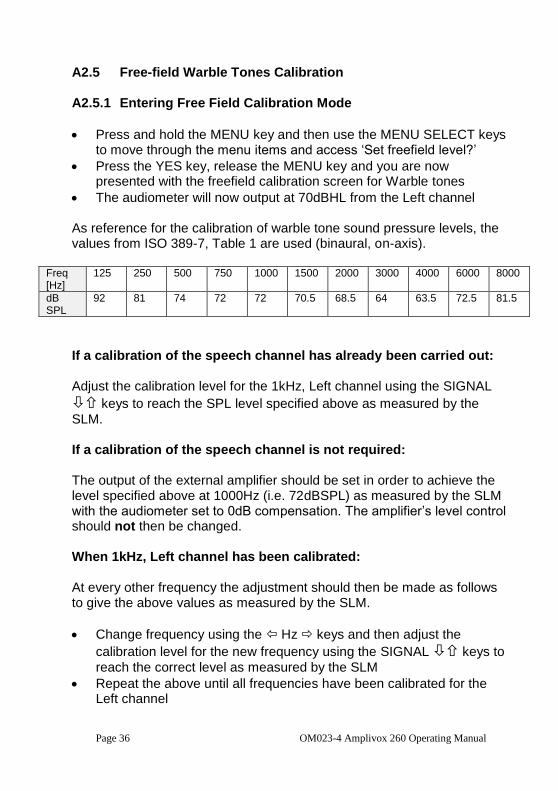
The audiometer will now output at 70dBHL from the Left channel As reference for the calibration of warble tone sound pressure levels, the values from ISO 389-7, Table 1 are used (binaural, on-axis).
Freq [Hz]
125 250 500 750 1000 1500 2000 3000 4000 6000 8000
dB SPL
92 81 74 72 72 70.5 68.5 64 63.5 72.5 81.5
If a calibration of the speech channel has already been carried out: Adjust the calibration level for the 1kHz, Left channel using the SIGNAL
keys to reach the SPL level specified above as measured by the
SLM. If a calibration of the speech channel is not required: The output of the external amplifier should be set in order to achieve the level specified above at 1000Hz (i.e. 72dBSPL) as measured by the SLM with the audiometer set to 0dB compensation. The amplifier’s level control should not then be changed. When 1kHz, Left channel has been calibrated: At every other frequency the adjustment should then be made as follows to give the above values as measured by the SLM.
Change frequency using the Hz keys and then adjust the
calibration level for the new frequency using the SIGNAL keys to
reach the correct level as measured by the SLM
Repeat the above until all frequencies have been calibrated for the Left channel
OM023-4 Amplivox 260 Operating Manual Page 37
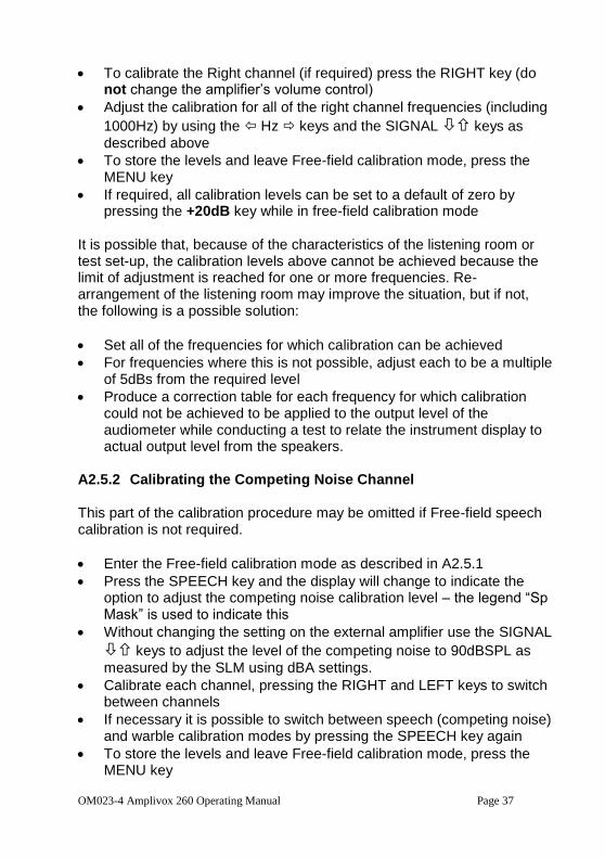
To calibrate the Right channel (if required) press the RIGHT key (do not change the amplifier’s volume control)
Adjust the calibration for all of the right channel frequencies (including
1000Hz) by using the Hz keys and the SIGNAL keys as
described above
To store the levels and leave Free-field calibration mode, press the MENU key
If required, all calibration levels can be set to a default of zero by pressing the +20dB key while in free-field calibration mode
It is possible that, because of the characteristics of the listening room or test set-up, the calibration levels above cannot be achieved because the limit of adjustment is reached for one or more frequencies. Re-arrangement of the listening room may improve the situation, but if not, the following is a possible solution:
Set all of the frequencies for which calibration can be achieved
For frequencies where this is not possible, adjust each to be a multiple of 5dBs from the required level
Produce a correction table for each frequency for which calibration could not be achieved to be applied to the output level of the audiometer while conducting a test to relate the instrument display to actual output level from the speakers.
A2.5.2 Calibrating the Competing Noise Channel This part of the calibration procedure may be omitted if Free-field speech calibration is not required.
Enter the Free-field calibration mode as described in A2.5.1
Press the SPEECH key and the display will change to indicate the option to adjust the competing noise calibration level – the legend “Sp Mask” is used to indicate this
Without changing the setting on the external amplifier use the SIGNAL
keys to adjust the level of the competing noise to 90dBSPL as
measured by the SLM using dBA settings.
Calibrate each channel, pressing the RIGHT and LEFT keys to switch between channels
If necessary it is possible to switch between speech (competing noise) and warble calibration modes by pressing the SPEECH key again
To store the levels and leave Free-field calibration mode, press the MENU key
Page 38 OM023-4 Amplivox 260 Operating Manual
A2.6 Free-field Live Speech Calibration Note: as stated in Appendix 1 of this operating manual, users should be aware that there is a growing body of professional opinion that Live Voice speech audiometry is generally not recommended. Exceptional skill and concentration are required to achieve accurate and consistent levels.
Connect a microphone to the MIC1 input on the audiometer
Press SPEECH repeatedly to ensure that ‘MIC’ is displayed in capitals at the bottom left of the display (indicating that the external microphone is selected)
The input signal is adjusted in 1dB steps with the MASKING keys
Input signal adjustment should be made to adjust for the operator’s voice to peak at the 0dB point on the LEVEL dB bar graph
If recorded speech has been calibrated no further action is necessary
If recorded speech has not been calibrated, the volume control of the amplifier should be adjusted so that the SLM reads 90dBSPL at the listening point with a 70dBHL setting on the instrument; note that this is an approximate setting only, as it is not possible to produce a true calibration signal in live speech
OM023-4 Amplivox 260 Operating Manual Page 39
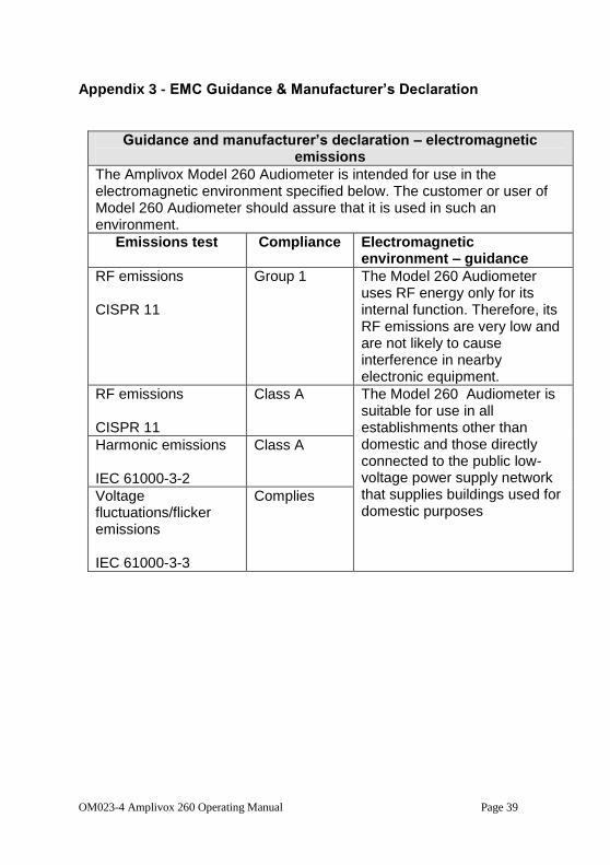
Appendix 3 - EMC Guidance & Manufacturer’s Declaration
Guidance and manufacturer’s declaration – electromagnetic emissions
The Amplivox Model 260 Audiometer is intended for use in the electromagnetic environment specified below. The customer or user of Model 260 Audiometer should assure that it is used in such an environment.
Emissions test Compliance Electromagnetic environment – guidance
RF emissions CISPR 11
Group 1 The Model 260 Audiometer uses RF energy only for its internal function. Therefore, its RF emissions are very low and are not likely to cause interference in nearby electronic equipment.
RF emissions CISPR 11
Class A The Model 260 Audiometer is suitable for use in all establishments other than domestic and those directly connected to the public low-voltage power supply network that supplies buildings used for domestic purposes
Harmonic emissions IEC 61000-3-2
Class A
Voltage fluctuations/flicker emissions IEC 61000-3-3
Complies
Page 40 OM023-4 Amplivox 260 Operating Manual
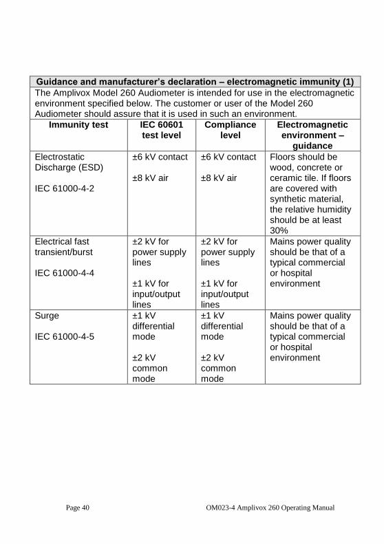
Guidance and manufacturer’s declaration – electromagnetic immunity (1)
The Amplivox Model 260 Audiometer is intended for use in the electromagnetic environment specified below. The customer or user of the Model 260 Audiometer should assure that it is used in such an environment.
Immunity test IEC 60601 test level
Compliance level
Electromagnetic environment –
guidance
Electrostatic Discharge (ESD) IEC 61000-4-2
±6 kV contact ±8 kV air
±6 kV contact ±8 kV air
Floors should be wood, concrete or ceramic tile. If floors are covered with synthetic material, the relative humidity should be at least 30%
Electrical fast transient/burst IEC 61000-4-4
±2 kV for power supply lines ±1 kV for input/output lines
±2 kV for power supply lines ±1 kV for input/output lines
Mains power quality should be that of a typical commercial or hospital environment
Surge IEC 61000-4-5
±1 kV differential mode ±2 kV common mode
±1 kV differential mode ±2 kV common mode
Mains power quality should be that of a typical commercial or hospital environment
OM023-4 Amplivox 260 Operating Manual Page 41
Immunity test IEC 60601 test level
Compliance level
Electromagnetic environment –
guidance
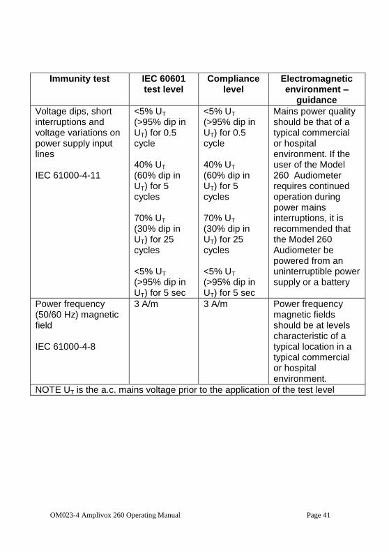
Voltage dips, short interruptions and voltage variations on power supply input lines IEC 61000-4-11
<5% UT (>95% dip in UT) for 0.5 cycle 40% UT (60% dip in UT) for 5 cycles 70% UT (30% dip in UT) for 25 cycles <5% UT (>95% dip in UT) for 5 sec
<5% UT (>95% dip in UT) for 0.5 cycle 40% UT (60% dip in UT) for 5 cycles 70% UT (30% dip in UT) for 25 cycles <5% UT (>95% dip in UT) for 5 sec
Mains power quality should be that of a typical commercial or hospital environment. If the user of the Model 260 Audiometer requires continued operation during power mains interruptions, it is recommended that the Model 260 Audiometer be powered from an uninterruptible power supply or a battery
Power frequency (50/60 Hz) magnetic field IEC 61000-4-8
3 A/m 3 A/m Power frequency magnetic fields should be at levels characteristic of a typical location in a typical commercial or hospital environment.
NOTE UT is the a.c. mains voltage prior to the application of the test level
Page 42 OM023-4 Amplivox 260 Operating Manual
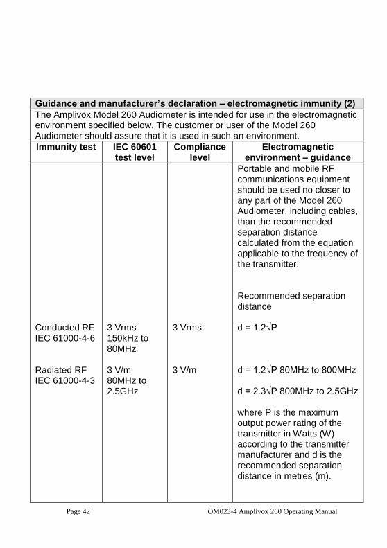
Guidance and manufacturer’s declaration – electromagnetic immunity (2)
The Amplivox Model 260 Audiometer is intended for use in the electromagnetic environment specified below. The customer or user of the Model 260 Audiometer should assure that it is used in such an environment.
Immunity test IEC 60601 test level
Compliance level
Electromagnetic environment – guidance
Conducted RF IEC 61000-4-6 Radiated RF IEC 61000-4-3
3 Vrms 150kHz to 80MHz 3 V/m 80MHz to 2.5GHz
3 Vrms 3 V/m
Portable and mobile RF communications equipment should be used no closer to any part of the Model 260 Audiometer, including cables, than the recommended separation distance calculated from the equation applicable to the frequency of the transmitter. Recommended separation distance d = 1.2√P d = 1.2√P 80MHz to 800MHz d = 2.3√P 800MHz to 2.5GHz where P is the maximum output power rating of the transmitter in Watts (W) according to the transmitter manufacturer and d is the recommended separation distance in metres (m).
OM023-4 Amplivox 260 Operating Manual Page 43
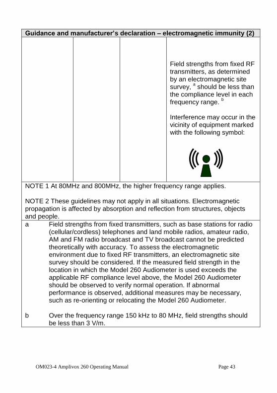
Guidance and manufacturer’s declaration – electromagnetic immunity (2)
Field strengths from fixed RF transmitters, as determined by an electromagnetic site survey,
a should be less than
the compliance level in each frequency range.
b
Interference may occur in the vicinity of equipment marked with the following symbol:
NOTE 1 At 80MHz and 800MHz, the higher frequency range applies. NOTE 2 These guidelines may not apply in all situations. Electromagnetic propagation is affected by absorption and reflection from structures, objects and people.
a Field strengths from fixed transmitters, such as base stations for radio (cellular/cordless) telephones and land mobile radios, amateur radio, AM and FM radio broadcast and TV broadcast cannot be predicted theoretically with accuracy. To assess the electromagnetic environment due to fixed RF transmitters, an electromagnetic site survey should be considered. If the measured field strength in the location in which the Model 260 Audiometer is used exceeds the applicable RF compliance level above, the Model 260 Audiometer should be observed to verify normal operation. If abnormal performance is observed, additional measures may be necessary, such as re-orienting or relocating the Model 260 Audiometer.
b Over the frequency range 150 kHz to 80 MHz, field strengths should
be less than 3 V/m.
Page 44 OM023-4 Amplivox 260 Operating Manual
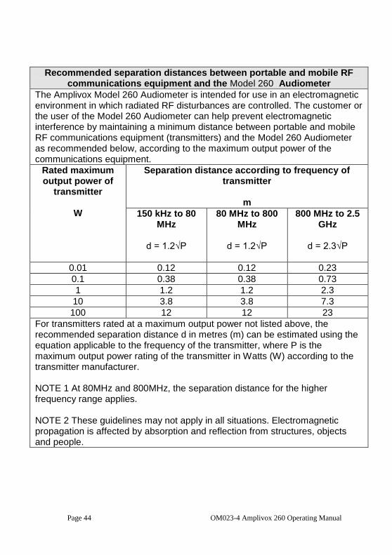
Recommended separation distances between portable and mobile RF communications equipment and the Model 260 Audiometer
The Amplivox Model 260 Audiometer is intended for use in an electromagnetic environment in which radiated RF disturbances are controlled. The customer or the user of the Model 260 Audiometer can help prevent electromagnetic interference by maintaining a minimum distance between portable and mobile RF communications equipment (transmitters) and the Model 260 Audiometer as recommended below, according to the maximum output power of the communications equipment.
Rated maximum output power of
transmitter
W
Separation distance according to frequency of transmitter
m
150 kHz to 80 MHz
d = 1.2√P
80 MHz to 800 MHz
d = 1.2√P
800 MHz to 2.5 GHz
d = 2.3√P
0.01 0.12 0.12 0.23
0.1 0.38 0.38 0.73
1 1.2 1.2 2.3
10 3.8 3.8 7.3
100 12 12 23
For transmitters rated at a maximum output power not listed above, the recommended separation distance d in metres (m) can be estimated using the equation applicable to the frequency of the transmitter, where P is the maximum output power rating of the transmitter in Watts (W) according to the transmitter manufacturer. NOTE 1 At 80MHz and 800MHz, the separation distance for the higher frequency range applies. NOTE 2 These guidelines may not apply in all situations. Electromagnetic propagation is affected by absorption and reflection from structures, objects and people.
OM023-4 Amplivox 260 Operating Manual Page 45
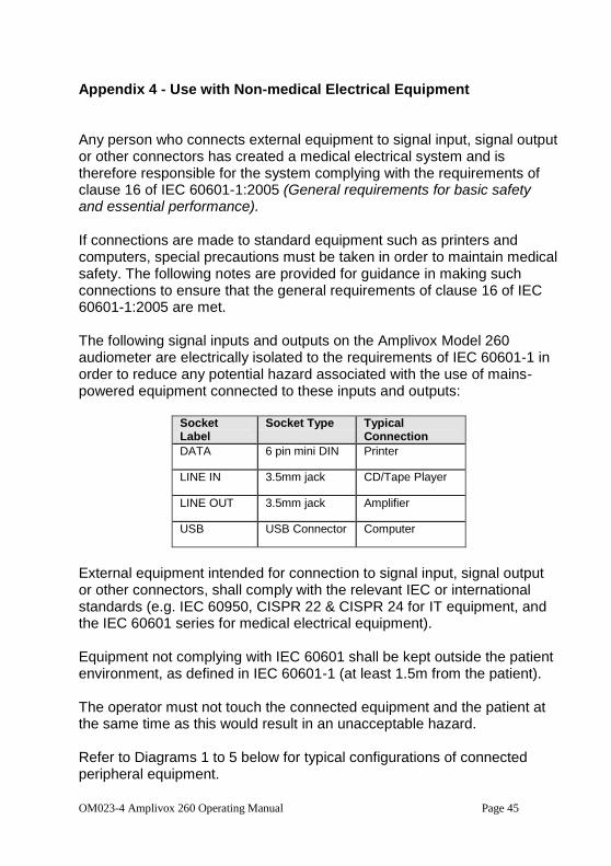
Appendix 4 - Use with Non-medical Electrical Equipment Any person who connects external equipment to signal input, signal output or other connectors has created a medical electrical system and is therefore responsible for the system complying with the requirements of clause 16 of IEC 60601-1:2005 (General requirements for basic safety and essential performance). If connections are made to standard equipment such as printers and computers, special precautions must be taken in order to maintain medical safety. The following notes are provided for guidance in making such connections to ensure that the general requirements of clause 16 of IEC 60601-1:2005 are met. The following signal inputs and outputs on the Amplivox Model 260 audiometer are electrically isolated to the requirements of IEC 60601-1 in order to reduce any potential hazard associated with the use of mains-powered equipment connected to these inputs and outputs:
Socket Label
Socket Type Typical Connection
DATA 6 pin mini DIN Printer
LINE IN 3.5mm jack CD/Tape Player
LINE OUT 3.5mm jack Amplifier
USB USB Connector Computer
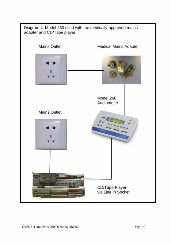
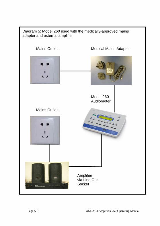
External equipment intended for connection to signal input, signal output or other connectors, shall comply with the relevant IEC or international standards (e.g. IEC 60950, CISPR 22 & CISPR 24 for IT equipment, and the IEC 60601 series for medical electrical equipment). Equipment not complying with IEC 60601 shall be kept outside the patient environment, as defined in IEC 60601-1 (at least 1.5m from the patient). The operator must not touch the connected equipment and the patient at the same time as this would result in an unacceptable hazard. Refer to Diagrams 1 to 5 below for typical configurations of connected peripheral equipment.
Page 46 OM023-4 Amplivox 260 Operating Manual
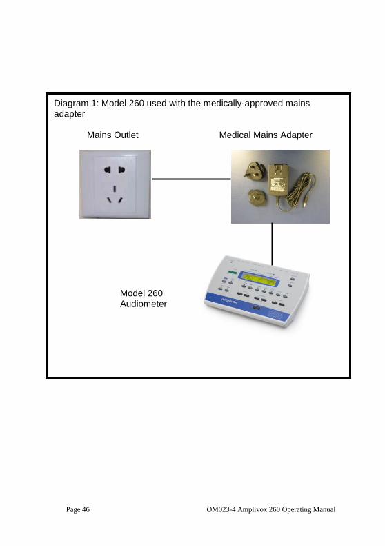
Diagram 1: Model 260 used with the medically-approved mains adapter Mains Outlet Medical Mains Adapter Model 260 Audiometer
OM023-4 Amplivox 260 Operating Manual Page 47
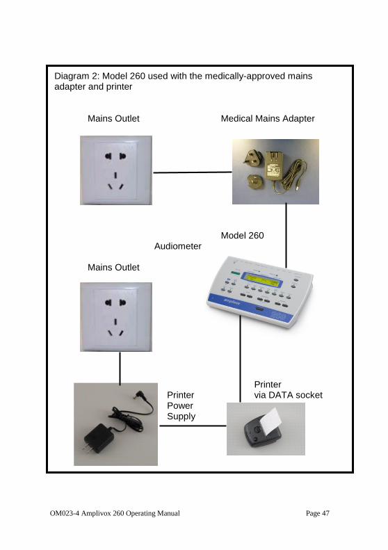
Diagram 2: Model 260 used with the medically-approved mains adapter and printer Mains Outlet Medical Mains Adapter
Model 260 Audiometer
Mains Outlet Printer
Printer via DATA socket Power Supply
Page 48 OM023-4 Amplivox 260 Operating Manual
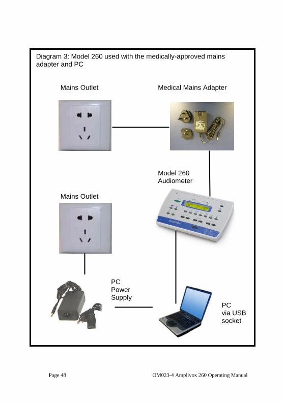
Diagram 3: Model 260 used with the medically-approved mains adapter and PC Mains Outlet Medical Mains Adapter
Model 260 Audiometer
Mains Outlet
PC Power Supply
PC via USB socket
OM023-4 Amplivox 260 Operating Manual Page 49
Diagram 4: Model 260 used with the medically-approved mains adapter and CD/Tape player Mains Outlet Medical Mains Adapter
Model 260 Audiometer
Mains Outlet
CD/Tape Player via Line In Socket
Page 50 OM023-4 Amplivox 260 Operating Manual
Diagram 5: Model 260 used with the medically-approved mains adapter and external amplifier Mains Outlet Medical Mains Adapter
Model 260 Audiometer
Mains Outlet
Amplifier via Line Out Socket