amcon lensometer user’s manual manual.pdf · 1-800-255-6161• fax 1-800-397-0013 amcon...
TRANSCRIPT

1-800-255-6161• Fax 1-800-397-0013www.amconlabs.com
AMCON LENSOMETER
USER’S MANUALEQ-6001

CONTENTS
Description and Usage............................................................................................................................................ 2
Main Technical Index............................................................................................................................................. 2
Principle of Operation............................................................................................................................................ 2
Functions of Major Components .......................................................................................................................... 3
Eyepiece ............................................................................................................................................................ 3
Eyepiece Reticule and Marker Reticule......................................................................................................... 3
Reading Division Board................................................................................................................................... 4
Prism Compensation Device ........................................................................................................................... 4
Lens Pressing Unit ........................................................................................................................................... 5
Lens Pushing Unit ............................................................................................................................................ 5
Printing Unit..................................................................................................................................................... 5
Objective Lens Bearing Seat ........................................................................................................................... 6
Diopter Measuring Handwheels ..................................................................................................................... 6
Astigmatism Axis Measuring Handwheel...................................................................................................... 6
Illuminating Bulb Chamber............................................................................................................................ 7
Instrument’s Inclination Regulating Handle................................................................................................. 7
Operation Instruction ............................................................................................................................................ 7
Preparation before Measurement................................................................................................................... 7
Points of Attention in Operation..................................................................................................................... 8
Placement of Lens ............................................................................................................................................ 8
Measurement of Spherical Lens ..................................................................................................................... 8
Measurement of Sphero-Cylindrical lens ...................................................................................................... 8
Measurement of Prism Lens ........................................................................................................................... 9
Demarcation of Lens...................................................................................................................................... 10
Maintenance of Instrument ................................................................................................................................. 10
Common Trouble Shooting ................................................................................................................................. 10

2
DESCRIPTION AND USAGE The lensometer is used to measure the power of the spherical lens, power of the cylindrical lens, cylindrical lens axis, prism diopter, prism basal angle, and contact lens diopter power.
MAIN TECHNICAL INDEX
Range of Diopter Measurement 0 to +/-25D Minimum Scale Value 0.125D at 0 to +/-5D 0.25D at +/-5D to +/-25D Astigmatism Axis of Cylindrical Lens 0 to 180º Minimum Scale Value 1º Prism Diopter 0 to 20Δ Minimum Scale Value 1Δ Prism Base Angle 0 to 180º Minimum Scale Value 1º Regulation of Ocular Visibility +/-5D Size of Lens 16mm to 80mm Overall Dimensions of Device 108.25 in X 51.25 in X 179 in Weight 12.5 lbs. Lighting Lamp 220V / 110V 15W
PRINCIPLE OF OPERATION
This instrument consists of two coaxial optical systems. Light from the (1) light source passes through (2) color filter to lighten (3) marker reticule. Through (4) measuring objective lens and (7) objective lens, the (3) marker reticule forms its image on (8) eyepiece through (12) front lens and (14) back lens. At this time, the eye is able to clearly observe the images of (3) reticule, (8) eyepiece, and (10) reading reticule.
During the operation, place lens at position of (5) diaphragm, turn and axially move (3) marker reticule so that it is imaged clearly. Then the scale interval shown on the (10) reading division board is just the diopter numerical value.

Fig. 1 – Diagram of Optical Principle
(1)Light Source (2)Color Filter (3)Marker Reticule (4)Measuring Objective Lens (5)Diaphragm (6)Prism
Compensation Device (7)Objective Lens (8)Eyepiece Reticule (9)Eyepiece (10)Reading Division Board (11)Reflect Lens (12)Front Lens (13)Right Angle Prism (14)Back Lens
FUNCTIONS OF MAJOR COMPONENTS
Eyepiece (Fig. 2) The eyepiece is equipped with a spiral focusing unit whose range of focusing is +/-5D so as to suit various refractive errors.
Fig. 2
Eyepiece Reticule and Marker Reticule (Fig. 3 & Fig. 4) Reticule in the field of view of eyepiece is shown as Fig. 3. The reticule is divided with measuring scale and dividing disc of prism degree. Integer degree of prism is directly read on the measuring scale and decimal one estimated according to the degree on the measuring scale. The dividing disc is ruled with an interval of 5º. The marker reticule is shown as Fig. 4. Three long green lines are in the horizontal position.
3

Reading Division Board (Fig. 5) In (9) eyepiece’s field of vision, the reading window is in the lower part of (8) eyepiece reticule. The range of reading (8) eyepiece reticule is +/-25D. The graduations between 0 and +/-5D are at an interval of 0.125D. Those between +/-5D and +/-25D are at an interval of 0.25D.
Prism Compensation Device (Fig. 6) The (6) prism compensation device is needed when measuring a lens diopter value above 5Δ. There are two lines of graduation on the prism compensation device. The upper line measures the angle from 0º to 180º at 5º intervals. The lower line measures prism diopters in the range from 0 to 15Δ in each direction at 1Δ intervals.
Fig. 6
4

Lens Pressing Unit (Fig. 7) Three plastic pressing feet with springs are used to so that the surface of the lens can be pressed without the lens surface being damaged. To operate, lift the lens pressing bracket so that the lens pressing unit lowers to press the lens. After use, raise the lens pressing unit.
Fig. 7
Lens Pushing Unit (Fig. 8) The unit is used to fix the position of the lens to be measured. During operation, turn the lens pushing handle backward to push the lens pushing board forward. After use, turn the lens pushing handle forward to withdraw the lens pushing board. During measurement, first press the lens with the lens pressing unit and slightly move the lens so that it aims right at the center. Then fix it with the lens pushing unit.
Fig. 8
Printing Unit (Fig. 9) The unit has three identical point making pens connected in line. The pen in the middle is used to set the center of the lens, and the connected line of printing points made by these three pens are used to demarcate the angle of axis astigmatism and base angle of the prism lens. When printing is needed, turn the holder of point-making pens and apply ink to the front end (small convex) of three pens. This makes it convenient to print the ink on the lens swiftly.
Fig. 9
5

Objective Lens Bearing Seat (Fig. 10) This while nylon part securely supports the surface of any shaped lens without damaging the lens surface. The objective lens is shown below. There are three lock screws.
Fig. 10
Diopter Measuring Handwheels (Fig. 11) The diopter measuring handwheels are located on either side of the lensometer. They can be rotated smoothly and steadily to adjust the focus until the observer can clearly see the indication of the lens diopter through the reading window.
Fig. 11
Astigmatism Axis Measuring Handwheel (Fig. 12) This handwheel is used to measure and fix the axis of the cylindrical lens and the base angle of the prism lens.
Fig. 12
6
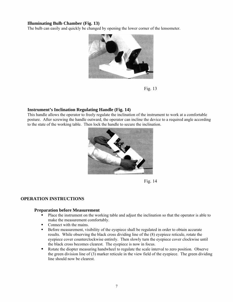
Illuminating Bulb Chamber (Fig. 13) The bulb can easily and quickly be changed by opening the lower corner of the lensometer.
Fig. 13
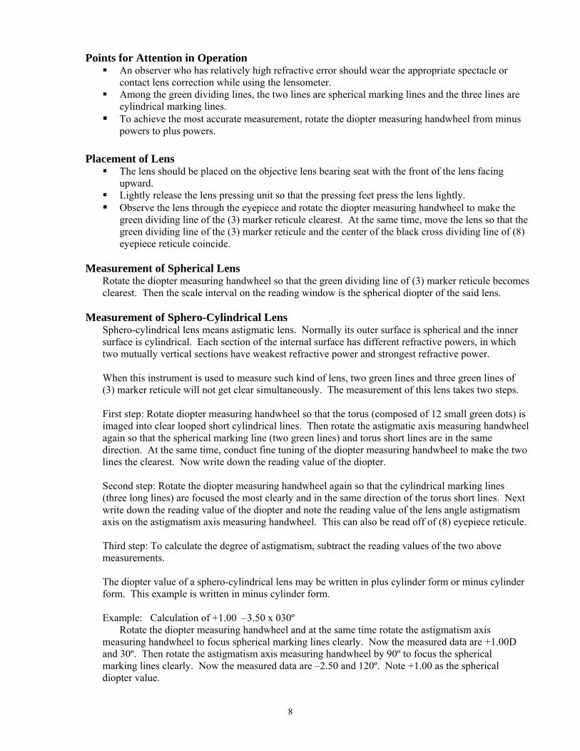
Instrument’s Inclination Regulating Handle (Fig. 14) This handle allows the operator to freely regulate the inclination of the instrument to work at a comfortable posture. After screwing the handle outward, the operator can incline the device to a required angle according to the state of the working table. Then lock the handle to secure the inclination.
Fig. 14
OPERATION INSTRUCTIONS
Preparation before Measurement Place the instrument on the working table and adjust the inclination so that the operator is able to
make the measurement comfortably. Connect with the mains. Before measurement, visibility of the eyepiece shall be regulated in order to obtain accurate
results. While observing the black cross dividing line of the (8) eyepiece reticule, rotate the eyepiece cover counterclockwise entirely. Then slowly turn the eyepiece cover clockwise until the black cross becomes clearest. The eyepiece is now in focus.
Rotate the diopter measuring handwheel to regulate the scale interval to zero position. Observe the green division line of (3) marker reticule in the view field of the eyepiece. The green dividing line should now be clearest.
7
8
Points for Attention in Operation An observer who has relatively high refractive error should wear the appropriate spectacle or
contact lens correction while using the lensometer. Among the green dividing lines, the two lines are spherical marking lines and the three lines are
cylindrical marking lines. To achieve the most accurate measurement, rotate the diopter measuring handwheel from minus
powers to plus powers. Placement of Lens
The lens should be placed on the objective lens bearing seat with the front of the lens facing upward.
Lightly release the lens pressing unit so that the pressing feet press the lens lightly. Observe the lens through the eyepiece and rotate the diopter measuring handwheel to make the
green dividing line of the (3) marker reticule clearest. At the same time, move the lens so that the green dividing line of the (3) marker reticule and the center of the black cross dividing line of (8) eyepiece reticule coincide.
Measurement of Spherical Lens
Rotate the diopter measuring handwheel so that the green dividing line of (3) marker reticule becomes clearest. Then the scale interval on the reading window is the spherical diopter of the said lens.
Measurement of Sphero-Cylindrical Lens
Sphero-cylindrical lens means astigmatic lens. Normally its outer surface is spherical and the inner surface is cylindrical. Each section of the internal surface has different refractive powers, in which two mutually vertical sections have weakest refractive power and strongest refractive power. When this instrument is used to measure such kind of lens, two green lines and three green lines of (3) marker reticule will not get clear simultaneously. The measurement of this lens takes two steps. First step: Rotate diopter measuring handwheel so that the torus (composed of 12 small green dots) is imaged into clear looped short cylindrical lines. Then rotate the astigmatic axis measuring handwheel again so that the spherical marking line (two green lines) and torus short lines are in the same direction. At the same time, conduct fine tuning of the diopter measuring handwheel to make the two lines the clearest. Now write down the reading value of the diopter. Second step: Rotate the diopter measuring handwheel again so that the cylindrical marking lines (three long lines) are focused the most clearly and in the same direction of the torus short lines. Next write down the reading value of the diopter and note the reading value of the lens angle astigmatism axis on the astigmatism axis measuring handwheel. This can also be read off of (8) eyepiece reticule. Third step: To calculate the degree of astigmatism, subtract the reading values of the two above measurements. The diopter value of a sphero-cylindrical lens may be written in plus cylinder form or minus cylinder form. This example is written in minus cylinder form. Example: Calculation of +1.00 –3.50 x 030º Rotate the diopter measuring handwheel and at the same time rotate the astigmatism axis measuring handwheel to focus spherical marking lines clearly. Now the measured data are +1.00D and 30º. Then rotate the astigmatism axis measuring handwheel by 90º to focus the spherical marking lines clearly. Now the measured data are –2.50 and 120º. Note +1.00 as the spherical diopter value.

Now rotate the diopter measuring handwheel and at the same time rotate the astigmatism axis measuring handwheel to focus spherical marking lines clearly once more. Now the reading in the window is +1.00, which is the same as the first reading. Then rotate the diopter measuring handwheel to focus the cylindrical marking lines clearly. At this time, the reading on the window is –2.50D, which is the same as the second reading. The astigmatism is –3.50D, because (-2.50D)-(+1.00D)= -3.50D. The axis direction is read directly off of the astigmatism axis measuring handwheel, which is 30º, as shown in Fig. 15 & Fig. 16.
Fig. 15 Image at +1.00D Fig. 16 Image at –2.50D
The final power measured is+1.00 -3.50 x 030º, which can be converted to –2.50 +3.50 x 120º.
Calculation of Prismatic Lens To measure a prismatic lens below 5Δ, place the prismatic lens on the objective lens bearing seat
and aim its optical center at the center of the optical axis. Rotate the diopter measuring handwheel to focus the lines of the (3) marker reticule clearly. The marking lines can be seen to deviate from the center of (8) eyepiece reticule. The deviating direction is the base direction of the prism lens. Rotate the astigmatism axis measuring handwheel so that the middle one of the three green marking lines passes through the center of the (8) eyepiece reticule. The value of the base angle of the prismatic lens can be read off according to the astigmatism axis measuring handwheel. The prism diopters can be estimated according to the reading on the (8) eyepiece reticule as shown in Fig. 17.
To measure a prismatic lens higher than 5Δ, the prism compensation device will be used. Rotate the diopter measuring handwheel and turn the angle to adjust the division line on (3) marker reticule to the proper position. Then sum the readings from the (8) eyepiece reticule and the prism compensation device equals the prism diopter of the lens. The base angle can be read from the prism compensation device.
9

10
Demarcation of Lens For demarcation of a spherical lens, rotate the diopter measuring handwheel to focus the lines of
the (3) marker reticule clearly. Lightly move the lens to find the right optical center. Make three-point printing marks with the printer.
For demarcation of the axis of a sphero-cylindrical lens, rotate the astigmatism axis measuring handwheel to the required angle. Then rotate the diopter measuring handwheel while turning the lens to focus the cylindrical marking lines clearly. Lightly move the lens to find the right optical center. Make three-point printing marks with the printer.
For demarcation prismatic lens base, rotate the astigmatism axis measuring handwheel to the required angle. Then rotate the diopter measuring handwheel to focus the lines of the (3) marker reticule clearly. Lightly turn the prism lens so that the middle of the three green marking lines passes through the center of the (8) eyepiece reticule. Make printing point marks by the use of the printer.
MAINTENANCE Do not dismantle the lensometer, as the accuracy will be compromised. Store the lensometer in a dry, cool, indoor place in order to assure precise working condition. Prevent the instrument from severe vibration or impact in order to avoid damage or loosening parts. When changing the bulb, make sure the bulb is cool before touching. Always keep the instrument clean. Do not touch the surfaces of the optical parts. Dust shall be cleaned
with an absorbent cotton-tipped applicator dipped with a mixture of ethanol and ether. After each use, clean the instrument and cover it with a dust shield.
COMMON TROUBLE SHOOTING Problem Reason Solution
Bulb will not light up.
Mains are not connected.
Connect with the mains.
Cannot see eyepiece reticule when
adjusting the eyepiece readings.
Observer has too much
uncorrected refractive error.
Wear a refractive correction when using the lensometer.
Green marking image cannot be
seen.
Bulb cannot be lighted or
Dust shield is still on.
Connect with mains or Take off dust shield.
Green marking image cannot be seen clearly.
Dust accumulates on optical lens.
Clean it using cotton
dipped in cleaning solution.
Deviation of the center
of the green marking image.
Lock screws are loose.
Remove objective lens shield,
regulate three screws, lock them.
Translocation of the printing unit.
Loosening of limit
screw or loosening of connecting screws.
Regulate limit screw & lock
or regulate connecting screws & lock.