amca publication 511-10 (rev. 2016 · asia amca sdn bhd no. 7, jalan silc 1/6, kawasan...
TRANSCRIPT
AIR MOVEMENT AND CONTROLASSOCIATION INTERNATIONAL, INC.
30 West University DriveArlington Heights, IL 60004-1893 U.S.A.
E-Mail : [email protected] Web: www.amca.orgTel: (847) 394-0150 Fax: (847) 253-0088
The Air Movement and Control Association International Inc. is a not-for-profit international association of the world’s manufacturers of related air system equipment, primarily but not limited to fans, louvers, dampers, air curtains, airflow measurement stations, acoustic attenuators and other air system components for the industrial, commercial and residential markets.
The International Authority on Air System Components
AIR MOVEMENT AND CONTROLASSOCIATION INTERNATIONAL, INC.
AMCA Publication 511-10
(Rev. 2016)Certified Ratings Program Product Rating Manual for
Air Control Devices

AMCA Publication 511-10 (Rev. 2016)
Certified Ratings Program Product Rating Manual for Air Control Devices
Air Movement and Control Association International 30 West University Drive Arlington Heights, Illinois
60004
AMCA Publications Authority AMCA Publication 511-10 (Rev. 2016) was adopted by the membership of the Air Movement and
Control Association International Inc. on March 24, 2016. The 2016 revision includes changes to the backdraft damper leakage section will allow
manufacturers to show compliance with the new 2015 IECC and ASHRAE 90.1 - 2013 leakage requirements for non-motorized dampers. The proposal increases the number of samples required to be leakage tested from one to three.
Copyright © 2007 by Air Movement and Control Association International Inc.
All rights reserved. Reproduction or translation of any part of this work beyond that permitted by Sections 107 and 108 of the United States Copyright Act without the permission of the copyright owner is unlawful. Requests for permission or further information should be addressed to the executive director, Air Movement and Control Association International Inc. at 30 West University Drive, Arlington Heights, IL 60004-1893 U.S.A.
Objections Air Movement and Control Association International Inc. will consider and take action upon all
written complaints regarding its standards, certification programs, or interpretations thereof. For information on procedures for submitting and handling complaints, write to:
Air Movement and Control Association International 30 West University Drive Arlington Heights, IL 60004-1893 U.S.A.
European AMCA Avenue des Arts, numéro 46 à Bruxelles (1000 Bruxelles)
Asia AMCA Sdn Bhd No. 7, Jalan SiLC 1/6, Kawasan Perindustrian SiLC Nusajaya, Mukim Jelutong, 79200 Nusajaya, Johor Malaysia
Disclaimer AMCA uses its best efforts to produce publications for the benefit of the industry and the public in
light of available information and accepted industry practices. However, AMCA does not guarantee, certify or assure the safety or performance of any products, components or systems tested, designed, installed or operated in accordance with AMCA publications or that any tests conducted under its publications will be non-hazardous or free from risk.

Review Committee Marty Gissel Greenheck Fan Company Committee Chair Mike Steele The Airolite Company, LLC Jacob Carr American Warming and Ventilation Jeff Blake Construction Specialties Bin Ngo Daniel Mechanic Eric Gohring Mestek Inc. Michael J. Bulzomi Nailor Industries Inc. Matt Remington Pottorff Randal Geedey Pottorff Dan Huber Ruskin Manufacturing Co. Dane Carey TAMCO Dampers Jason Haley Ventex Inc. Tim Orris AMCA International

Contents
AMCA Publications ............................................................................................................................................................... 2
Review Committee ................................................................................................................................................................ 3
1. Purpose .............................................................................................................................................................................. 8
2. Scope .................................................................................................................................................................................. 8
3. Definitions and Symbols .................................................................................................................................................. 8
3.1 Definitions ....................................................................................................................................................................................... 8
3.2 Symbols ........................................................................................................................................................................................... 9
4. Data Submittal Requirements .......................................................................................................................................... 9
5. Required Catalog Statements ........................................................................................................................................ 10
5.1 Licensed product statement ............................................................................................................................................................ 10
5.2 Licensed performance statement .................................................................................................................................................... 10
5.3 Appurtenances statement ............................................................................................................................................................... 10
6. General Guidelines for Air Control Products ............................................................................................................... 10
6.1 Manufacturer’s responsibility ........................................................................................................................................................ 10
6.2 AMCA staff responsibility ............................................................................................................................................................. 10
6.3 Rating development ....................................................................................................................................................................... 11
6.4 Aerodynamically similar products ................................................................................................................................................. 11
6.5 Nameplated products ..................................................................................................................................................................... 11
7. Check Test Tolerances and Required Tests ................................................................................................................ 11
7.1 Licensee’s duty .............................................................................................................................................................................. 11
7.2 Tolerances ...................................................................................................................................................................................... 11
7.3 Required tests ................................................................................................................................................................................. 12
8. Louver | Air Performance Rating Requirements .......................................................................................................... 12
8.1 Testing requirements ...................................................................................................................................................................... 12
8.2 Calculated performance ................................................................................................................................................................. 12
8.3 Published ratings ............................................................................................................................................................................ 13
9. Louver | Wind Driven Rain Rating Requirements ........................................................................................................ 13
9.1 Testing requirements ...................................................................................................................................................................... 13
9.2 Calculated performance ................................................................................................................................................................. 14
9.3 Published ratings ............................................................................................................................................................................ 14
10. Louver | Wind Driven Sand Rating Requirements ..................................................................................................... 15
10.1 Testing requirements .................................................................................................................................................................... 15
10.2 Calculated performance ............................................................................................................................................................... 15
10.3 Published ratings .......................................................................................................................................................................... 15
11. Louver | Water Penetration Rating Requirements ..................................................................................................... 16
11.1 Testing requirements .................................................................................................................................................................... 16
11.2 Calculated performance ............................................................................................................................................................... 16
11.3 Published ratings .......................................................................................................................................................................... 17
12. Acoustical Louver | Sound Performance Rating Requirements .............................................................................. 18
12.1 Testing requirements .................................................................................................................................................................... 18
12.2 Calculated performance ............................................................................................................................................................... 18
12.3 Published ratings .......................................................................................................................................................................... 19
13. Adjustable Louver | Air Leakage Rating Requirements ............................................................................................ 19
13.1 Testing requirements .................................................................................................................................................................... 19
13.2 Calculated performance ............................................................................................................................................................... 19
13.3 Published ratings .......................................................................................................................................................................... 19
14. Damper | Air Performance Rating Requirements ...................................................................................................... 20
14.1 Testing requirements .................................................................................................................................................................... 20
14.2 Calculated performance ............................................................................................................................................................... 21
14.3 Published ratings .......................................................................................................................................................................... 21
15. Volume Control Damper | Air Leakage Rating Requirements .................................................................................. 21
15.1 Testing requirements .................................................................................................................................................................... 22
15.2 Calculated performance ............................................................................................................................................................... 22
15.3 Published ratings .......................................................................................................................................................................... 22
16. Ultra-Low-Leakage Damper | Air Leakage Rating Requirements ............................................................................ 24
16.1 Testing requirements .................................................................................................................................................................... 24
16.2 Calculated performance ............................................................................................................................................................... 24
16.3 Published ratings .......................................................................................................................................................................... 24
17. Bubble-Tight Damper | Air Leakage Rating Requirements ....................................................................................... 25
17.1 Testing requirements .................................................................................................................................................................... 25
17.2 Calculated performance ............................................................................................................................................................... 25
17.3 Published ratings .......................................................................................................................................................................... 26
18. UL-Classified Damper | Air Leakage Rating Requirements ...................................................................................... 26
18.1 Testing requirements .................................................................................................................................................................... 26
18.2 Calculated performance ............................................................................................................................................................... 27
18.3 Published ratings .......................................................................................................................................................................... 27
19. Backdraft Damper | Air Leakage Rating Requirements ............................................................................................ 27
19.1 Testing requirements .................................................................................................................................................................... 27
19.2 Calculated performance ............................................................................................................................................................... 28
19.3 Published ratings .......................................................................................................................................................................... 28
20. Gravity Ventilator (Excluding Louver Penthouses) | Air Performance Rating Requirements .............................. 28
20.1 Testing requirements .................................................................................................................................................................... 29
20.2 Calculated performance ............................................................................................................................................................... 29
20.3 Published ratings .......................................................................................................................................................................... 29
21. Round Spiral Duct | Air Leakage Rating Requirements ............................................................................................ 31
21.1 Testing requirements .................................................................................................................................................................... 31
21.2 Calculated performance ............................................................................................................................................................... 31
21.3 Published ratings .......................................................................................................................................................................... 31
22. Louver/Damper | Energy Efficiency Rating Requirements ....................................................................................... 31
22.1 Testing requirements .................................................................................................................................................................... 31
22.2 Calculated performance ............................................................................................................................................................... 32
22.3 Published ratings .......................................................................................................................................................................... 32
23. Transverse Duct Connectors | Air Leakage Rating Requirements .......................................................................... 32
23.1 Testing requirements .................................................................................................................................................................... 32
23.2 Calculated performance ............................................................................................................................................................... 34
23.3 Published ratings .......................................................................................................................................................................... 34
Annex A Electronic Catalogs (Normative) ...................................................................................................................... 35
A.1 Introduction ................................................................................................................................................................................... 35
A.2 Scope ............................................................................................................................................................................................. 35
A.3 Definitions ..................................................................................................................................................................................... 35
A.4 Statements ..................................................................................................................................................................................... 35
A.5 Certification of electronic performance data ................................................................................................................................. 36
A.6 Version numbers ........................................................................................................................................................................... 37
A.7 Certified performance identification ............................................................................................................................................. 37
A.8 AMCA directory listings ............................................................................................................................................................... 37
Annex B Measurements (Normative) .............................................................................................................................. 37
B.1 Calculating louver free area .......................................................................................................................................................... 38
B.2 Calculating damper area ................................................................................................................................................................ 39
Annex C Developing Air Control Product Catalogs (Informative) ................................................................................ 39
C.1 Louver Air Performance Test Report and Catalog Example ......................................................................................................... 41
C.2 Louver Wind-Driven Rain Test Report and Catalog Example ...................................................................................................... 43
C.3 Louver Water Penetration Test Report and Catalog Example ....................................................................................................... 46
C.4 Louver Sound Performance Test Report and Catalog Example .................................................................................................... 48
C.5 Adjustable Louver Leakage Performance Test Report and Catalog Example ............................................................................... 50
C.6 Damper Air Performance Test Report and Catalog Example ........................................................................................................ 52
C.7 Volume Control Damper Leakage Performance Test Report and Catalog Example .................................................................... 54
C.8 Ultra-Low-Leakage Damper Leakage Test Report and Catalog Example .................................................................................... 57
C.9 Bubble-Tight Damper Leakage Performance Test Report and Catalog Example ......................................................................... 59
C.10 Backdraft Damper Leakage Performance Test Report and Catalog Example ............................................................................. 61
C.11 Gravity Ventilator Air Performance Test Report and Catalog Example ..................................................................................... 63
C.12 Spiral Duct Leakage Performance Test Report and Catalog Example ........................................................................................ 65
C.13 Flat Oval Spiral Duct Leakage Performance Test Report and Catalog Example ........................................................................ 67

1. Purpose AMCA Publication 511 dictates proper presentation of data and other required technical procedures for certification of air control devices under the AMCA Certified Ratings Program. This manual shall be used in conjunction with the current edition of AMCA Publication 11. 2. Scope The products within the scope of this program are air control devices for use in general ventilation and air conditioning systems. This program shall apply only to complete cataloged series of sizes. It shall not apply to individual sizes in a series, or part of a series of sizes, or to special units on which catalog ratings are not published. The AMCA Certified Ratings seal shall be used only in connection with the specifically licensed device. The AMCA Seal shall be used only on complete units. The application of the AMCA seal to individual component parts, such as blades, frames, etc., is not permitted. 3. Definitions and Symbols 3.1 Definitions All definitions found in AMCA Publication 11, as well as the definitions in this section, apply to this program. 3.1.1 Appurtenance Appurtenance is any item in the air stream or on the inlet or discharge of the air control device that may affect the performance of the air control device. An appurtenance shall be considered a part of the air control device if it is in place when the device is tested for performance rating and the effect of the appurtenance is included in the cataloged performance rating. 3.1.2 AMCA Certified Ratings Program The Certified Ratings Program is a program for certifying a product’s performance ratings, as defined in this document. 3.1.3 Performance rating(s) Performance ratings are data generated from actual tested products used to derive the certified and published information. 3.1.4 Shall and should The word shall indicates a mandatory requirement; the word should indicates an advisory statement. 3.1.5 Aerodynamically similar Louver and damper designs are considered to be aerodynamically similar if the profiles of the components in the air stream are geometrically similar. The blades shall be in relative position to the frame and the center-to-center dimensions shall be the same. Frame, blade stops and blade profiles may have slight variances due to manufacturing methods. Blades must have the same streamline shape in that their leading and trailing edges shall be dimensionally equal. The overall angle or curvature of the blade must be the same. Slight deviations in material thickness shall not reduce the overall free area by more than 5% for dampers and 2.5% for louvers. Blade seals shall have the same profile, be of the same durometer and be secured to the blade in the same manner. In addition to the requirements described above, louver or damper models claiming aerodynamic similarity for the purpose of certifying leakage performance or energy efficiency performance shall meet the following criteria:
The frames and blades shall have a modulus of elasticity (E) greater than or equal to the originally licensed model.
The blade action (i.e., whether the damper is parallel or opposed blade) shall be the same as the originally licensed model.
The method used for interconnecting the damper or louver blades (i.e., the linkage) shall be the same as the originally licensed model.
The jamb seal shall be the same as the originally licensed model.
The blade axle bearing assemblies shall be the same as the originally licensed model.
3.1.6 Volume control damper A volume control damper is a device which, when mounted to a duct or opening, is used to vary the volume of air through the duct or opening. It can be operated manually or mechanically and may have one or more blades. For the purposes of this document, dampers meeting the definition of a backdraft damper or a UL-classified damper shall not be considered a volume control damper. Ultra-low-leakage dampers and bubble-tight dampers may be tested as volume control dampers. 3.1.7 Backdraft damper A backdraft damper is a damper that, when mounted in a duct or opening, permits airflow in one direction and prevents airflow in the opposite direction. 3.1.8 UL-Classified damper For the purpose of this document, a UL-classified damper is a device which is classified to Underwriters Laboratories category code EMME (Dampers for Fire Barriers and Smoke Applications) as a smoke damper, combination fire and smoke damper, or corridor damper. 3.1.9 Ultra-low-leakage damper This is a device that leaks 35.2 L/s/m2 (6.93 cfm/ft2) or less at a static pressure differential of 3.0 kPa (12 in. wg). Leakage performance of ultra-low-leakage dampers may be certified at any static pressure differential 3.0 kPa (12 in. wg.) or greater as long as the leakage does not exceed 2 × (Ps)0.5. 3.1.10 Bubble-tight damper A bubble-tight damper is a device whose leakage performance at the tested pressure meets the requirements of the bubble test as described in ANSI/AMCA Standard 500-D. 3.2 Symbols
Symbol Description
ΔPs Pressure drop or pressure differential
4. Data Submittal Requirements AMCA staff shall accept test data obtained in only the AMCA laboratory or an AMCA-accredited laboratory. Test data shall conform to the test standard used. For each air control device and certification type covered by this program, a separate section of testing and rating requirements is included. The specific procedures and test data necessary for preparing performance ratings are defined in Sections 8 through 23. The following data shall be submitted with all CRP-5 application forms: Results of the test(s), corrected to standard air density, where applicable Photograph of each test setup Performance curve(s) of the test results, with test points identified Dimensional drawings For all louvers, one additional drawing as shown in Annex B, along with the methodology that the manufacturer uses to determine the ‘A’ and ‘B’ spaces for all louver sizes that are in the product line. For louvers tested with a drain pan, one additional drawing showing the height and setback dimensions of the drain pan
For gravity ventilators, one additional drawing as shown in Section 20 5. Required Catalog Statements 5.1 Licensed product statement The following statement shall be printed prominently and immediately adjacent to the reproduction of the AMCA Certified Ratings seal: “[Licensee’s name] certifies that the [product designation] shown hereon [or herein] is licensed to bear the AMCA seal. The ratings shown are based on tests and procedures performed in accordance with AMCA Publication 511 and comply with the requirements of the AMCA Certified Ratings Program.” 5.2 Licensed performance statement When performance ratings are licensed to use the AMCA Certified Ratings seal, the following additional statement shall be printed prominently and immediately adjacent to the performance ratings: “The AMCA Certified Ratings seal applies to [certification type] ratings.” Where [certification type] is one of the following:
Air Performance
Water Penetration and Air Performance
Water Penetration, Wind-Driven Rain, and Air Performance
Wind-Driven Rain and Air Performance
Water Penetration, Air Performance, and Sound
Sound and Air Performance
Energy Efficiency and Air Performance
Air Leakage
Air Leakage and Energy Efficiency
Air Leakage and Air Performance
Air Leakage, Air Performance, and Energy Efficiency
Efficiency
5.3 Appurtenances statement Where published ratings include the effect of an appurtenance, the following statement shall be placed adjacent to the ratings: “Ratings include the effect of [insert appurtenance here].” 6. General Guidelines for Air Control Products 6.1 Manufacturer’s responsibility It is incumbent on manufacturers to develop catalog performance ratings of the licensed products so that the product provided to their customers performs within the tolerances allowed by the Certified Ratings Program. This section provides general guidelines on the process of developing air performance ratings from tests, and Sections 8 through 23 define specific requirements for each type of product. 6.2 AMCA staff responsibility
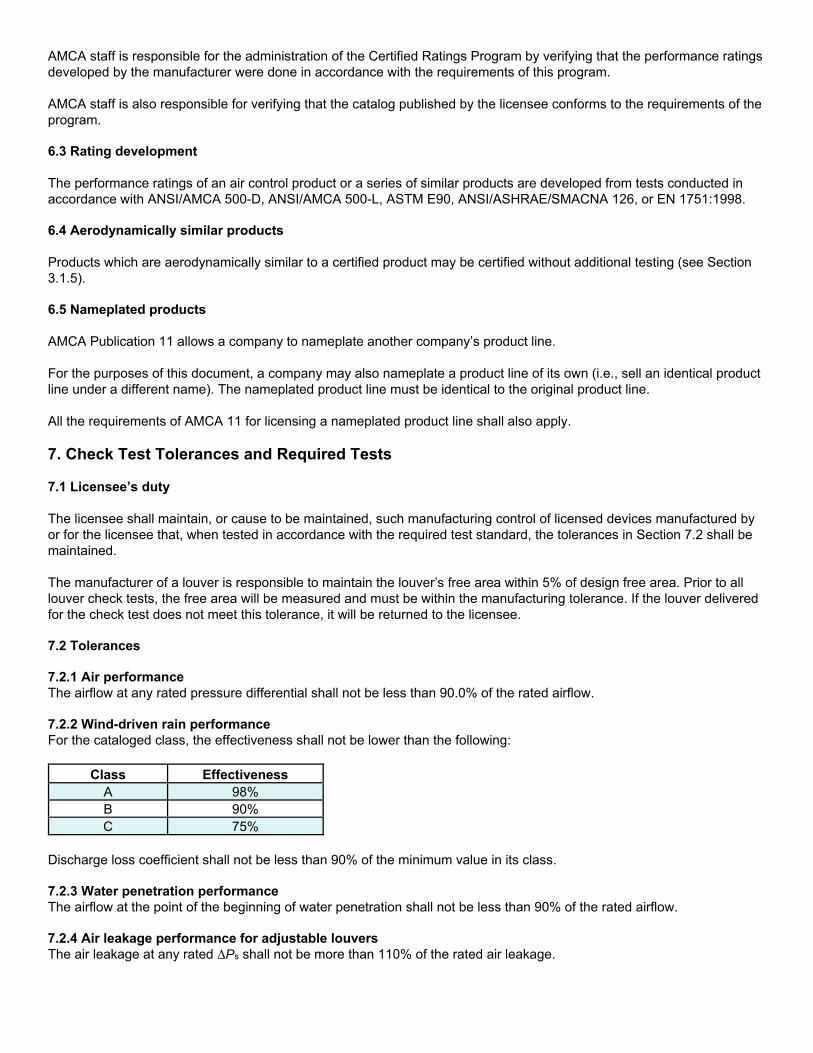
AMCA staff is responsible for the administration of the Certified Ratings Program by verifying that the performance ratings developed by the manufacturer were done in accordance with the requirements of this program. AMCA staff is also responsible for verifying that the catalog published by the licensee conforms to the requirements of the program. 6.3 Rating development The performance ratings of an air control product or a series of similar products are developed from tests conducted in accordance with ANSI/AMCA 500-D, ANSI/AMCA 500-L, ASTM E90, ANSI/ASHRAE/SMACNA 126, or EN 1751:1998. 6.4 Aerodynamically similar products Products which are aerodynamically similar to a certified product may be certified without additional testing (see Section 3.1.5). 6.5 Nameplated products AMCA Publication 11 allows a company to nameplate another company’s product line. For the purposes of this document, a company may also nameplate a product line of its own (i.e., sell an identical product line under a different name). The nameplated product line must be identical to the original product line. All the requirements of AMCA 11 for licensing a nameplated product line shall also apply. 7. Check Test Tolerances and Required Tests 7.1 Licensee’s duty The licensee shall maintain, or cause to be maintained, such manufacturing control of licensed devices manufactured by or for the licensee that, when tested in accordance with the required test standard, the tolerances in Section 7.2 shall be maintained. The manufacturer of a louver is responsible to maintain the louver’s free area within 5% of design free area. Prior to all louver check tests, the free area will be measured and must be within the manufacturing tolerance. If the louver delivered for the check test does not meet this tolerance, it will be returned to the licensee. 7.2 Tolerances 7.2.1 Air performance The airflow at any rated pressure differential shall not be less than 90.0% of the rated airflow. 7.2.2 Wind-driven rain performance For the cataloged class, the effectiveness shall not be lower than the following:
Class Effectiveness A 98% B 90% C 75%
Discharge loss coefficient shall not be less than 90% of the minimum value in its class. 7.2.3 Water penetration performance The airflow at the point of the beginning of water penetration shall not be less than 90% of the rated airflow. 7.2.4 Air leakage performance for adjustable louvers The air leakage at any rated ΔPs shall not be more than 110% of the rated air leakage.
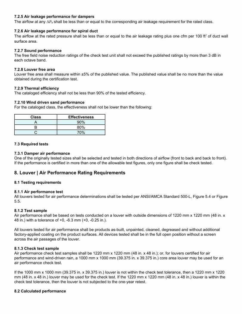
7.2.5 Air leakage performance for dampers The airflow at any ΔPs shall be less than or equal to the corresponding air leakage requirement for the rated class. 7.2.6 Air leakage performance for spiral duct The airflow at the rated pressure shall be less than or equal to the air leakage rating plus one cfm per 100 ft2 of duct wall surface area. 7.2.7 Sound performance The free field noise reduction ratings of the check test unit shall not exceed the published ratings by more than 3 dB in each octave band. 7.2.8 Louver free area Louver free area shall measure within ±5% of the published value. The published value shall be no more than the value obtained during the certification test. 7.2.9 Thermal efficiency The cataloged efficiency shall not be less than 90% of the tested efficiency. 7.2.10 Wind driven sand performance For the cataloged class, the effectiveness shall not be lower than the following:
Class Effectiveness A 90% B 80% C 70%
7.3 Required tests 7.3.1 Damper air performance One of the originally tested sizes shall be selected and tested in both directions of airflow (front to back and back to front). If the performance is certified in more than one of the allowable test figures, only one figure shall be check tested. 8. Louver | Air Performance Rating Requirements 8.1 Testing requirements 8.1.1 Air performance test All louvers tested for air performance determinations shall be tested per ANSI/AMCA Standard 500-L, Figure 5.4 or Figure 5.5. 8.1.2 Test sample Air performance shall be based on tests conducted on a louver with outside dimensions of 1220 mm x 1220 mm (48 in. x 48 in.) with a tolerance of +0, -6.3 mm (+0, -0.25 in.). All louvers tested for air performance shall be products as-built, unpainted, cleaned, degreased and without additional factory-applied coating on the product surfaces. All devices tested shall be in the full open position without a screen across the air passages of the louver. 8.1.3 Check test sample Air performance check test samples shall be 1220 mm x 1220 mm (48 in. x 48 in.); or, for louvers certified for air performance and wind-driven rain, a 1000 mm x 1000 mm (39.375 in. x 39.375 in.) core area louver may be used for an air performance check test. If the 1000 mm x 1000 mm (39.375 in. x 39.375 in.) louver is not within the check test tolerance, then a 1220 mm x 1220 mm (48 in. x 48 in.) louver may be used for the check test. If the 1220 mm x 1220 mm (48 in. x 48 in.) louver is within the check test tolerance, then the louver is not subjected to the one-year retest. 8.2 Calculated performance
8.2.1 Proportionality Air performance of any size louver may be calculated from tests of one size for the same design type using free area velocity versus ΔPs within the limits of extrapolation of test data specified in Section 8.3.3. 8.2.2 Blade spacing variations Where the design blade spacing varies in size, the manufacturer shall submit test data from tests of both the smallest and greatest blade spacing to show that all test data will fall within the specified tolerances. 8.2.3 Extrapolation Extrapolation from test data is permissible. 8.3 Published ratings 8.3.1 Required data Published ratings of air performance shall include the following:
Maximum ΔPs for a specified free area velocity
Data corrected to standard air density
AMCA figure or figures to which air performance is tested
Test sample size
8.3.2 Rounding of data Pressure drop information presented in SI units shall be rounded to the nearest pascal (e.g., 5 Pa, not 5.1 Pa) when testing results in pressure drop values of 1 Pa or greater. Published data may be rounded to one digit after the decimal point (e.g., 0.8 Pa, not 0.83 Pa) when testing results in pressure drop values less than 1 Pa. Pressure drop information presented in I-P units shall be rounded to a maximum of two digits after the decimal point (e.g., 0.02 in. wg, not 0.025 in. wg) when testing results in pressure drop values of 0.01 in. wg or greater. Published data may be rounded to three digits after the decimal point (e.g., 0.003 in. wg, not 0.0032 in. wg) when testing results in pressure drop values less than 0.01 in. wg, provided that the test equipment is accurate and calibrated to read three decimal places. 8.3.3 Extrapolation The portion of the air performance curve obtained by extrapolation shall be charted with a broken line and must be a smooth continuation of the adjacent portion of the curve. The air performance shall not be extrapolated more than 50% above the maximum tested static pressure or 50% below the minimum tested static pressure. 8.3.4 Mode tested The published ratings shall indicate the mode tested (intake or exhaust), or test data shall be provided to AMCA that indicates that the data published is worst case. 8.3.5 Free area Published ratings shall include a table of louver free area for the product line. The maximum increment between sizes shall be 305 mm (12 in.). 8.3.6 Drain pan statement If an optional drain pan is used when testing a louver, see Section 5.3. 9. Louver | Wind Driven Rain Rating Requirements 9.1 Testing requirements 9.1.1 Wind driven rain test All testing shall be performed in accordance with ANSI/AMCA Standard 500-L, Figure 5.11.
9.1.2 Test sample Wind driven rain performance shall be based on tests conducted on a louver that has one of the following:
A core area of 1000 mm x 1000 mm (39.375 in. x 39.375 in.) with a tolerance of ±3 mm (±1/8 in.) with an extended frame
Extended frame outside dimensions of 1213 mm x 1213 mm (47.75 in. x 47.75 in.) with a tolerance of +5, -0 mm (+0.19, -0 in.)
Outside dimensions of 1213 mm x 1213 mm (47.75 in. x 47.75 in.) with a tolerance of +5, -0 mm (+0.19, -0 in.)
9.2 Calculated performance 9.2.1 Penetration class The penetration class shall be determined by the effectiveness in accordance with ANSI/AMCA Standard 500-L (see Table 2). 9.2.2 Discharge loss coefficient The discharge loss coefficient, given in Table 1, shall be determined in accordance with ANSI/AMCA Standard 500-L. 9.3 Published ratings 9.3.1 Wind driven rain performance
Published ratings of wind-driven rain performance of louvers shall be a statement of their ability to reject simulated rain. Published ratings shall include the following:
Wind velocity
Rainfall rate
Core velocity
Effectiveness
Penetration class (see Table 2)
Discharge loss coefficient class (see Table 1)
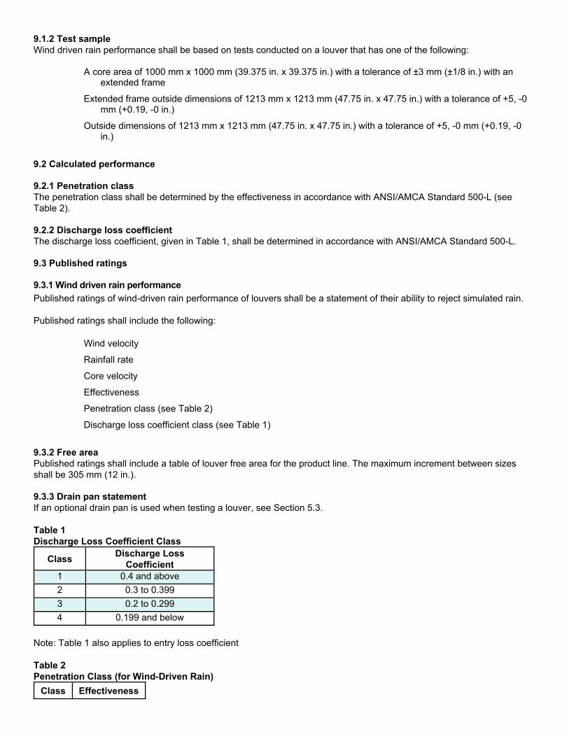
9.3.2 Free area Published ratings shall include a table of louver free area for the product line. The maximum increment between sizes shall be 305 mm (12 in.). 9.3.3 Drain pan statement If an optional drain pan is used when testing a louver, see Section 5.3. Table 1 Discharge Loss Coefficient Class
Class Discharge Loss
Coefficient 1 0.4 and above
2 0.3 to 0.399
3 0.2 to 0.299
4 0.199 and below
Note: Table 1 also applies to entry loss coefficient Table 2 Penetration Class (for Wind-Driven Rain)
Class Effectiveness
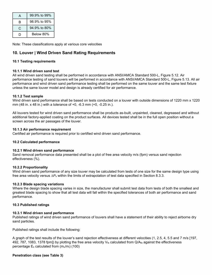
A 99.9% to 99%
B 98.9% to 95%
C 94.9% to 80%
D Below 80%
Note: These classifications apply at various core velocities 10. Louver | Wind Driven Sand Rating Requirements 10.1 Testing requirements 10.1.1 Wind driven sand test All wind driven sand testing shall be performed in accordance with ANSI/AMCA Standard 500-L, Figure 5.12. Air performance testing of sand louvers will be performed in accordance with ANSI/AMCA Standard 500-L, Figure 5.13. All air performance and wind driven sand performance testing shall be performed on the same louver and the same test fixture unless the same louver model and design is already certified for air performance. 10.1.2 Test sample Wind driven sand performance shall be based on tests conducted on a louver with outside dimensions of 1220 mm x 1220 mm (48 in. x 48 in.) with a tolerance of +0, -6.3 mm (+0, -0.25 in.). All louvers tested for wind driven sand performance shall be products as-built, unpainted, cleaned, degreased and without additional factory-applied coating on the product surfaces. All devices tested shall be in the full open position without a screen across the air passages of the louver. 10.1.3 Air performance requirement Certified air performance is required prior to certified wind driven sand performance. 10.2 Calculated performance 10.2.1 Wind driven sand performance Sand removal performance data presented shall be a plot of free area velocity m/s (fpm) versus sand rejection effectiveness (%). 10.2.2 Proportionality Wind driven sand performance of any size louver may be calculated from tests of one size for the same design type using free area velocity versus ΔPs within the limits of extrapolation of test data specified in Section 8.3.3. 10.2.3 Blade spacing variations Where the design blade spacing varies in size, the manufacturer shall submit test data from tests of both the smallest and greatest blade spacing to show that all test data will fall within the specified tolerances of both air performance and sand performance. 10.3 Published ratings 10.3.1 Wind driven sand performance Published ratings of wind driven sand performance of louvers shall have a statement of their ability to reject airborne dry sand particles. Published ratings shall include the following: A graph of the test results of the louver’s sand rejection effectiveness at different velocities (1, 2.5, 4, 5.5 and 7 m/s [197, 492, 787, 1083, 1378 fpm]) by plotting the free area velocity Vfa calculated from Q/Afa against the effectiveness percentage Es calculated from (mu/mi) (100) Penetration class (see Table 3)
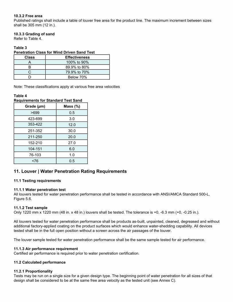
10.3.2 Free area Published ratings shall include a table of louver free area for the product line. The maximum increment between sizes shall be 305 mm (12 in.). 10.3.3 Grading of sand Refer to Table 4. Table 3 Penetration Class for Wind Driven Sand Test
Class Effectiveness A 100% to 90% B 89.9% to 80% C 79.9% to 70% D Below 70%
Note: These classifications apply at various free area velocities Table 4 Requirements for Standard Test Sand
Grade (µm) Mass (%)
>699 0.5
423-699 3.0
353-422 12.0
251-352 30.0
211-250 20.0
152-210 27.0
104-151 6.0
76-103 1.0
<76 0.5
11. Louver | Water Penetration Rating Requirements 11.1 Testing requirements 11.1.1 Water penetration test All louvers tested for water penetration performance shall be tested in accordance with ANSI/AMCA Standard 500-L, Figure 5.6. 11.1.2 Test sample Only 1220 mm x 1220 mm (48 in. x 48 in.) louvers shall be tested. The tolerance is +0, -6.3 mm (+0, -0.25 in.). All louvers tested for water penetration performance shall be products as-built, unpainted, cleaned, degreased and without additional factory-applied coating on the product surfaces which would enhance water-shedding capability. All devices tested shall be in the full open position without a screen across the air passages of the louver. The louver sample tested for water penetration performance shall be the same sample tested for air performance. 11.1.3 Air performance requirement Certified air performance is required prior to water penetration certification. 11.2 Calculated performance 11.2.1 Proportionality Tests may be run on a single size for a given design type. The beginning point of water penetration for all sizes of that design shall be considered to be at the same free area velocity as the tested unit (see Annex C).
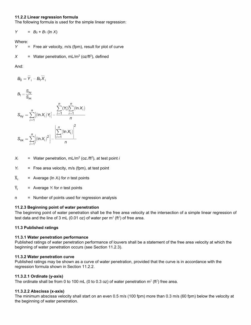
11.2.2 Linear regression formula The following formula is used for the simple linear regression: Y = B0 + B1 (ln X) Where: Y = Free air velocity, m/s (fpm), result for plot of curve X = Water penetration, mL/m2 (oz/ft2), defined And:
Xi = Water penetration, mL/m2 (oz./ft2), at test point i Yi = Free area velocity, m/s (fpm), at test point X = Average (ln Xi) for n test points Y = Average Yi for n test points n = Number of points used for regression analysis 11.2.3 Beginning point of water penetration The beginning point of water penetration shall be the free area velocity at the intersection of a simple linear regression of test data and the line of 3 mL (0.01 oz) of water per m2 (ft2) of free area. 11.3 Published ratings 11.3.1 Water penetration performance Published ratings of water penetration performance of louvers shall be a statement of the free area velocity at which the beginning of water penetration occurs (see Section 11.2.3). 11.3.2 Water penetration curve Published ratings may be shown as a curve of water penetration, provided that the curve is in accordance with the regression formula shown in Section 11.2.2. 11.3.2.1 Ordinate (y-axis) The ordinate shall be from 0 to 100 mL (0 to 0.3 oz) of water penetration m2 (ft2) free area. 11.3.2.2 Abscissa (x-axis) The minimum abscissa velocity shall start on an even 0.5 m/s (100 fpm) more than 0.3 m/s (60 fpm) below the velocity at the beginning of water penetration.

The maximum abscissa velocity shall be up to 0.5 m/s (100 fpm) past the 100 mL (0.3 oz) of water per m2 (ft2) of free area with a maximum velocity of 6.5 m/s (1300 fpm) (see Annex C). 11.3.2.3 Marking the beginning point of water penetration curve The starting coordinate of the water penetration curve shall be marked and/or labeled as the beginning point of water penetration. 11.3.3 Louver information The louver test size and test duration shall be included on published results of each catalog series. 11.3.4 Mullions The following special conditions apply for drainable blade louvers that are separated by an architectural or recessed mullion:
1. If the mullion contains provisions to drain water from the blades and head members away from the airstream, and if louver has been tested for water penetration, the use of the AMCA Certified Rating seal on this design is authorized when louver section falls within the catalog data.
2. If the mullion does not contain provisions to drain water from the blades and head members, the use of AMCA Certified Rating seal is not authorized.
11.3.5 Free area Published ratings shall include a table of louver free area for the product line. The maximum increment between sizes shall be 305 mm (12 in). 11.3.6 Drain pan statement If an optional drain pan is used when testing a louver, see Section 5.3. 11.3.7 Air performance ratings Air performance ratings shall be published in accordance with Section 8. 11.3.8 Mullion exclusion The performance of drainable blade louvers supplied with mullions that do not have provisions to drain water from the blades or head shall not be certified. 12. Acoustical Louver | Sound Performance Rating Requirements 12.1 Testing requirements 12.1.1 Sound performance test All transmission loss acoustical testing shall be in accordance with ASTM E90. 12.1.2 Test sample Test data shall be submitted for a 1220 mm x 1220 mm (48 in. x 48 in.) louver. The tolerance is +0, -6.3 mm (+0, -0.25 in.). 12.1.3 Air performance requirement
Certified air performance is required prior to sound performance certification. 12.2 Calculated performance 12.2.1 Free Field Noise Reduction Free field noise reduction shall be determined by adding 6 dB to the transmission loss (dB). 12.2.2 Proportionality Air performance of any size louver may be calculated from tests of one size for the same design type using free area velocity versus ΔPs within the limits of extrapolation of test data specified in Section 8.2.1.

12.2.3 Blade spacing variations Where the design blade spacing varies in size, the manufacturer shall submit test data from tests of both the smallest and greatest blade spacing to show that all test data will fall within the specified tolerances for both air performance and sound performance ratings. 12.3 Published ratings 12.3.1 Sound performance Acoustical ratings shall be stated as free field noise reduction (dB) in the 2nd through 7th octave bands. 12.3.2 Free area Published ratings shall include a table of louver free area for the product line. The maximum increment between sizes shall be 305 mm (12 in.). 12.3.3 Air performance ratings Air performance ratings shall be published in accordance with Section 8. 13. Adjustable Louver | Air Leakage Rating Requirements 13.1 Testing requirements 13.1.1 Air leakage test All testing for air leakage through closed adjustable louvers shall be per ANSI/AMCA Standard 500-L, Figure 5.4 or Figure 5.5. 13.1.2 Test samples Test data shall be submitted for the following sizes:
Minimum width x maximum height
Maximum width x minimum height
Maximum width x maximum height
13.1.3 Number of tests A minimum of two tests shall be conducted on each sample. The adjustable louver shall be cycled to full open and back to full closed between each test. 13.2 Calculated performance 13.2.1 Air leakage Air leakage performance of any size louver shall be calculated from tests of no less than three sizes (single panel design) of the same design. Data presented shall be a plot of L/s/m2 (cfm/ft2) of face area versus ΔPs that reflects the largest value of L/s/m2 (cfm/ft2) air leakage of the louvers tested at each value of ΔPs. 13.2.2 Blade spacing variations Where the design blade spacing varies, the manufacturer shall submit data from tests of both the smallest and greatest blade spacing to show that all test data will fall within the specified tolerances. 13.2.3 Extrapolation Extrapolation above the maximum or below the minimum test ΔPs shall not be permitted. 13.3 Published ratings 13.3.1 Air leakage performance Published ratings of air leakage performance shall be presented in either tabular form, graphical form or both as a statement of the maximum tested air leakage at the following:

A specified differential pressure
Standard air density
AMCA figure or figures to which air leakage performance is tested
13.3.2 Torque statement The following statement shall be included: “Data are based on the maximum torque of [#] N•m/m2 (in.-lb/ft2) applied to the louver during the test.” [Any number ending with a decimal greater than 0.02 shall be rounded to the next higher number, e.g., 6.12 N•m/m2 = 6.1 N•m/m2 and 6.13 N•m/m2 = 6.2 N•m/m2 (5.12 in.-lb/ft2 = 5.1 in.-lb/ft2 and 5.13 in. lb/ft2 = 5.2 in.*lb/ft2)] 13.3.3 Opening torque A table showing the opening torque may be included on the same page if it is labeled as “opening torque.” 13.3.4 Mode tested The rating shall indicate the mode tested (intake or exhaust) or test data will be provided to AMCA that indicates that the data published is worst case. 13.3.5 Operational statement Published data shall state the following: “Air leakage is based on operation between 10 °C - 40 °C (50 °F - 104 °F)” 14. Damper | Air Performance Rating Requirements 14.1 Testing requirements 14.1.1 Pressure drop test All testing for pressure drop determinations of single-blade, multi-blade or curtain dampers (excluding backdraft dampers) in the full open position shall be per ANSI/AMCA Standard 500-D, per at least one of Figures 5.1, 5.2, 5.3, 5.4, or 5.5. Testing shall be conducted in both directions of airflow (front to back and back to front). Vertically mounted backdraft dampers shall be mounted per Figure 5.4 or 5.5 so that the airflow assists opening of the dampers. Horizontally mounted backdraft dampers shall be tested per Test Figure 5.7A, 5.7B, 5.7E or 5.7F and such that the airflow assists in opening. 14.1.2 Test samples 14.1.2.1 Rectangular (Excluding backdraft dampers) Test data shall be submitted for the following sizes:
305 mm x 305 mm (12 in. x 12 in.)
610 mm x 610 mm (24 in. x 24 in.)
914 mm x 914 mm (36 in. x 36 in.)
305 mm x 1220 mm (12 in. x 48 in.)
1220 mm x 305 mm (48 in. x 12 in.)
The tolerance is +0, -6.3 mm (+0, -0.25 in.). If the maximum single section size is less than that shown above, a multi-section damper shall be tested if offered by the manufacturer. If any of the sizes listed above are not offered by the manufacturer, those sizes are not required to be tested or listed. A minimum of one of the sizes listed above must be tested for a product line to be eligible for certification. 14.1.2.2 Round (excluding backdraft dampers) Test data shall be submitted for the following sizes (diameters):
305 mm (12 in.)
610 mm (24 in.)
914 mm (36 in.)
If the smallest damper is larger than 305 mm (12 in.) or the largest damper is smaller than 914 mm (36 in.), three sizes shall be tested:
Largest
Smallest
Midway between the largest and smallest
14.1.2.3 Rectangular (backdraft dampers only) A 610 mm x 610 mm (24 in. x 24 in.) damper shall be tested. If the largest size damper produced is smaller than 610 mm x 610 mm (24 in. x 24 in.), the largest cataloged size shall be tested. The tolerance is +0, -6.3 mm (+0, -0.25 in.). 14.1.2.4 Round (backdraft dampers only) A 610 mm (24 in.) diameter damper shall be tested. If the largest size damper produced is smaller than 610 mm (24 in.), the largest cataloged size shall be tested. 14.2 Calculated performance 14.2.1 Extrapolation 14.2.1.1 Below test pressure Extrapolation below the minimum test static pressure drop shall be permitted, excluding backdraft dampers. 14.2.1.2 Above test pressure Extrapolation above the maximum test static pressure drop shall not be permitted. 14.2.1.3 Sizes Extrapolation outside of test sizes shall not be permitted. 14.3 Published ratings 14.3.1 Air performance Published ratings of air performance shall be a statement of the maximum static pressure drop for a specified airflow rate and at standard air density and the AMCA figure or figures tested for all required sizes. Except for backdraft dampers, the published performance for each size shall be from the worse performing of the two airflows. Ratings shall be published in tabular form, graphical form or both. 14.3.2 Rounding of data Pressure drop information presented in SI units shall be rounded to the nearest pascal (e.g., 5 Pa, not 5.1) when testing results in pressure drop values of 1 Pa or greater. Published data may be rounded to one digit after the decimal point (e.g., 0.8 Pa, not 0.83 Pa) when testing results in pressure drop values less than 1 Pa. Pressure drop information presented in I-P units shall be rounded to a maximum of two digits after the decimal point (e.g., 0.02 in. wg, not 0.025 in. wg) when testing results in pressure drop values of 0.01 in. wg or greater. Published data may be rounded to three digits after the decimal point (e.g., 0.003 in. wg, not 0.0032 in. wg) when testing results in pressure drop values less that 0.01 in. wg, provided that the test equipment is accurate and calibrated to read three decimal places. 14.3.3 Extrapolation The portion of the air performance curve obtained by extrapolation shall be charted with a broken line and must be a smooth continuation of the adjacent portion of the curve. The air performance shall not be extrapolated below 50% of the minimum tested static pressure. 15. Volume Control Damper | Air Leakage Rating Requirements
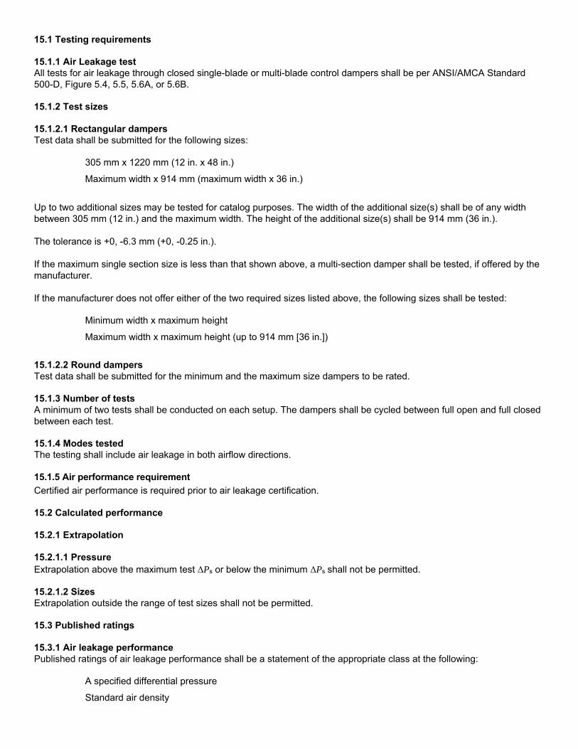
15.1 Testing requirements 15.1.1 Air Leakage test All tests for air leakage through closed single-blade or multi-blade control dampers shall be per ANSI/AMCA Standard 500-D, Figure 5.4, 5.5, 5.6A, or 5.6B. 15.1.2 Test sizes 15.1.2.1 Rectangular dampers Test data shall be submitted for the following sizes:
305 mm x 1220 mm (12 in. x 48 in.)
Maximum width x 914 mm (maximum width x 36 in.)
Up to two additional sizes may be tested for catalog purposes. The width of the additional size(s) shall be of any width between 305 mm (12 in.) and the maximum width. The height of the additional size(s) shall be 914 mm (36 in.). The tolerance is +0, -6.3 mm (+0, -0.25 in.). If the maximum single section size is less than that shown above, a multi-section damper shall be tested, if offered by the manufacturer. If the manufacturer does not offer either of the two required sizes listed above, the following sizes shall be tested:
Minimum width x maximum height
Maximum width x maximum height (up to 914 mm [36 in.])
15.1.2.2 Round dampers Test data shall be submitted for the minimum and the maximum size dampers to be rated. 15.1.3 Number of tests A minimum of two tests shall be conducted on each setup. The dampers shall be cycled between full open and full closed between each test. 15.1.4 Modes tested The testing shall include air leakage in both airflow directions. 15.1.5 Air performance requirement
Certified air performance is required prior to air leakage certification. 15.2 Calculated performance 15.2.1 Extrapolation 15.2.1.1 Pressure Extrapolation above the maximum test ΔPs or below the minimum ΔPs shall not be permitted. 15.2.1.2 Sizes Extrapolation outside the range of test sizes shall not be permitted. 15.3 Published ratings 15.3.1 Air leakage performance Published ratings of air leakage performance shall be a statement of the appropriate class at the following:
A specified differential pressure
Standard air density
AMCA figure or figures to which air leakage performance is tested
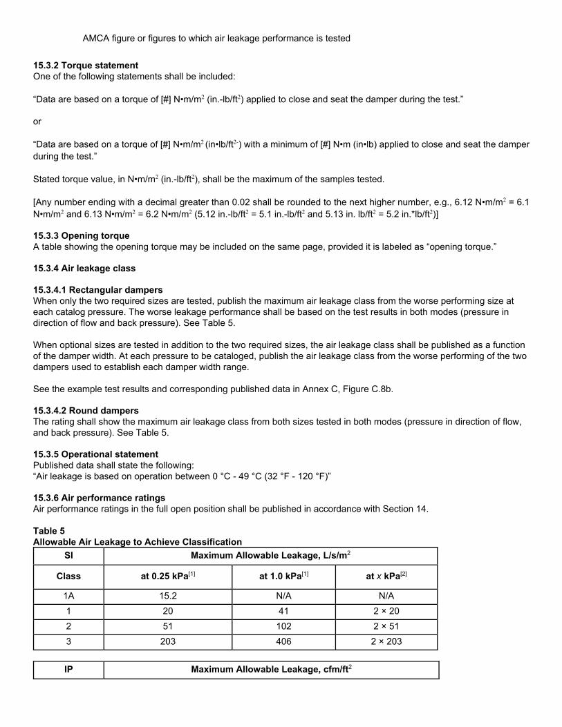
15.3.2 Torque statement One of the following statements shall be included: “Data are based on a torque of [#] N•m/m2 (in.-lb/ft2) applied to close and seat the damper during the test.” or “Data are based on a torque of [#] N•m/m2 (in•lb/ft2-) with a minimum of [#] N•m (in•lb) applied to close and seat the damper during the test.” Stated torque value, in N•m/m2 (in.-lb/ft2), shall be the maximum of the samples tested. [Any number ending with a decimal greater than 0.02 shall be rounded to the next higher number, e.g., 6.12 N•m/m2 = 6.1 N•m/m2 and 6.13 N•m/m2 = 6.2 N•m/m2 (5.12 in.-lb/ft2 = 5.1 in.-lb/ft2 and 5.13 in. lb/ft2 = 5.2 in.*lb/ft2)] 15.3.3 Opening torque A table showing the opening torque may be included on the same page, provided it is labeled as “opening torque.” 15.3.4 Air leakage class 15.3.4.1 Rectangular dampers When only the two required sizes are tested, publish the maximum air leakage class from the worse performing size at each catalog pressure. The worse leakage performance shall be based on the test results in both modes (pressure in direction of flow and back pressure). See Table 5. When optional sizes are tested in addition to the two required sizes, the air leakage class shall be published as a function of the damper width. At each pressure to be cataloged, publish the air leakage class from the worse performing of the two dampers used to establish each damper width range. See the example test results and corresponding published data in Annex C, Figure C.8b. 15.3.4.2 Round dampers The rating shall show the maximum air leakage class from both sizes tested in both modes (pressure in direction of flow, and back pressure). See Table 5. 15.3.5 Operational statement Published data shall state the following: “Air leakage is based on operation between 0 °C - 49 °C (32 °F - 120 °F)” 15.3.6 Air performance ratings Air performance ratings in the full open position shall be published in accordance with Section 14. Table 5 Allowable Air Leakage to Achieve Classification
SI Maximum Allowable Leakage, L/s/m2
Class at 0.25 kPa[1] at 1.0 kPa[1] at x kPa[2]
1A 15.2 N/A N/A
1 20 41 2 × 20
2 51 102 2 × 51
3 203 406 2 × 203
IP Maximum Allowable Leakage, cfm/ft2

Class at 1 in. wg[1] at 4 in. wg[1] at x in. wg[2]
1A 3 N/A N/A
1 4 8 × 4
2 10 20 × 10
3 40 80 × 40
Notes: [1] Required pressures; shall be cataloged [2] Any other pressure may be cataloged using these formulas 16. Ultra-Low-Leakage Damper | Air Leakage Rating Requirements 16.1 Testing requirements An ultra-low-leakage damper is defined as a device that leaks 35.2 L/s/m2 (6.93 cfm/ft2) or less at a static pressure differential of 3.0 kPa (12 in. wg). Leakage performance of ultra-low-leakage dampers may be certified at any static pressure differential 3.0 kPa (12 in. wg.) or greater as long as the leakage does not exceed 2 × (ΔPs)0.5. 16.1.1 Air leakage test All tests for air leakage through closed single-blade or multi-blade control dampers shall be per ANSI/AMCA 500-D, Figure 5.4, 5.5, 5.6A or 5.6B. 16.1.2 Test sizes 16.1.2.1 Rectangular test sizes Test data shall be submitted for the following sizes:
Minimum width x maximum height
Maximum width x minimum height
Maximum width x maximum height
16.1.2.2 Round test sizes Test data shall be submitted for the minimum and the maximum size dampers to be rated. 16.1.3 Number of tests A minimum of two tests shall be conducted on each setup. The dampers shall be cycled between full open and full closed between each test. 16.1.4 Modes tested The testing shall include air leakage in both airflow directions. 16.2 Calculated performance 16.2.1 Extrapolation 16.2.1.1 Pressure Extrapolation above the maximum test ΔPs or below the minimum ΔPs shall not be permitted. 16.2.1.2 Sizes Extrapolation outside the range of test sizes shall not be permitted. 16.3 Published ratings
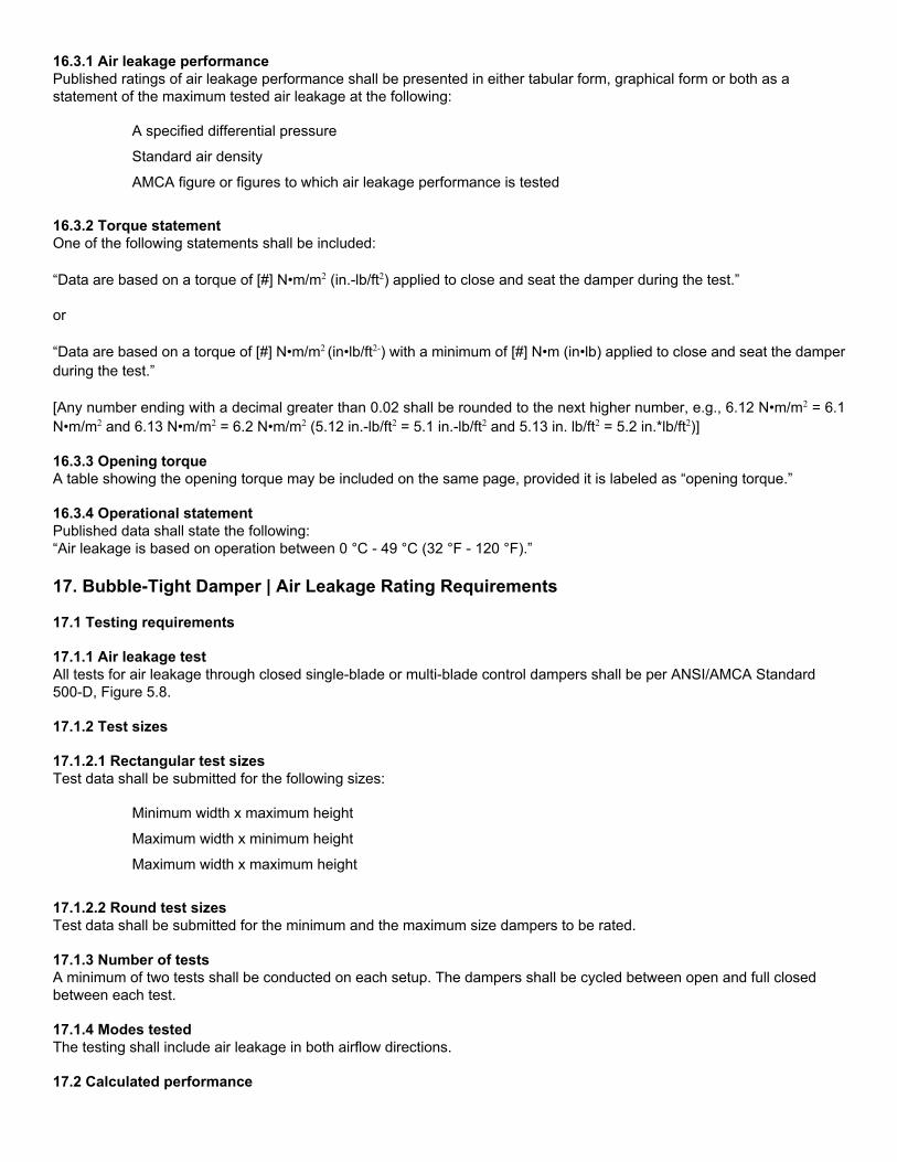
16.3.1 Air leakage performance Published ratings of air leakage performance shall be presented in either tabular form, graphical form or both as a statement of the maximum tested air leakage at the following:
A specified differential pressure
Standard air density
AMCA figure or figures to which air leakage performance is tested
16.3.2 Torque statement One of the following statements shall be included: “Data are based on a torque of [#] N•m/m2 (in.-lb/ft2) applied to close and seat the damper during the test.” or “Data are based on a torque of [#] N•m/m2 (in•lb/ft2-) with a minimum of [#] N•m (in•lb) applied to close and seat the damper during the test.” [Any number ending with a decimal greater than 0.02 shall be rounded to the next higher number, e.g., 6.12 N•m/m2 = 6.1 N•m/m2 and 6.13 N•m/m2 = 6.2 N•m/m2 (5.12 in.-lb/ft2 = 5.1 in.-lb/ft2 and 5.13 in. lb/ft2 = 5.2 in.*lb/ft2)] 16.3.3 Opening torque A table showing the opening torque may be included on the same page, provided it is labeled as “opening torque.” 16.3.4 Operational statement Published data shall state the following: “Air leakage is based on operation between 0 °C - 49 °C (32 °F - 120 °F).” 17. Bubble-Tight Damper | Air Leakage Rating Requirements 17.1 Testing requirements 17.1.1 Air leakage test All tests for air leakage through closed single-blade or multi-blade control dampers shall be per ANSI/AMCA Standard 500-D, Figure 5.8. 17.1.2 Test sizes 17.1.2.1 Rectangular test sizes Test data shall be submitted for the following sizes:
Minimum width x maximum height
Maximum width x minimum height
Maximum width x maximum height
17.1.2.2 Round test sizes Test data shall be submitted for the minimum and the maximum size dampers to be rated. 17.1.3 Number of tests A minimum of two tests shall be conducted on each setup. The dampers shall be cycled between open and full closed between each test. 17.1.4 Modes tested The testing shall include air leakage in both airflow directions. 17.2 Calculated performance

17.2.1 Extrapolation 17.2.1.1 Pressure Extrapolation above the maximum test ΔPs or below the minimum ΔPs shall not be permitted. 17.2.1.2 Sizes Extrapolation outside the range of test sizes shall not be permitted. 17.3 Published ratings 17.3.1 Air leakage performance Published ratings of air leakage performance for bubble-tight dampers shall be presented as the following statement: “Dampers are bubble-tight up to [x] Pa ([x] in. wg) differential pressure.” 17.3.2 Torque table and statement A table stating the damper size and required torque in N•m (in.-lb) and N•m/m2 (in.-lb/ft2) shall be included. The following statement shall be included with the table: “Data are based on the following torque required to close and seat the damper during the test.” 17.3.3 Opening torque A table showing the opening torque may be included. This optional table shall be labeled “opening torque.” 17.3.4 Operational statement Published data shall state the following: “Air leakage is based on operation between 0 °C - 49 °C (32 °F - 120 °F).” 18. UL-Classified Damper | Air Leakage Rating Requirements 18.1 Testing requirements 18.1.1 Test sample Damper shall be a UL-classified damper as defined in Section 3.1.8. 18.1.2 Air leakage test 18.1.2.1 Cycling before air leakage test Before the air leakage test, the damper shall be cycled open and closed. During this cycle, the UL test velocity corresponding to the highest velocity to which the damper is UL classified shall be applied across the open damper. The UL test ΔPs corresponding to the highest pressure to which the damper is UL classified to shall be applied across the closed damper. 18.1.2.2 Test figure All testing for air leakage shall be per ANSI/AMCA Standard 500-D, Figure 5.4, Figure 5.5 or Figure 5.9 at ambient temperatures. 18.1.2.3 Closing method The air leakage test shall be conducted with the appropriate springs, actuators or other closing devices, normally supplied with the UL-classified damper, applying the closing torque or force. 18.1.2.4 Modes tested The testing shall include air leakage in both airflow directions. 18.1.3 Check test sizes 18.1.3.1 Rectangular test sizes One of the following sizes shall be tested:
Minimum width x maximum height
Maximum width x minimum height
Maximum width x maximum height
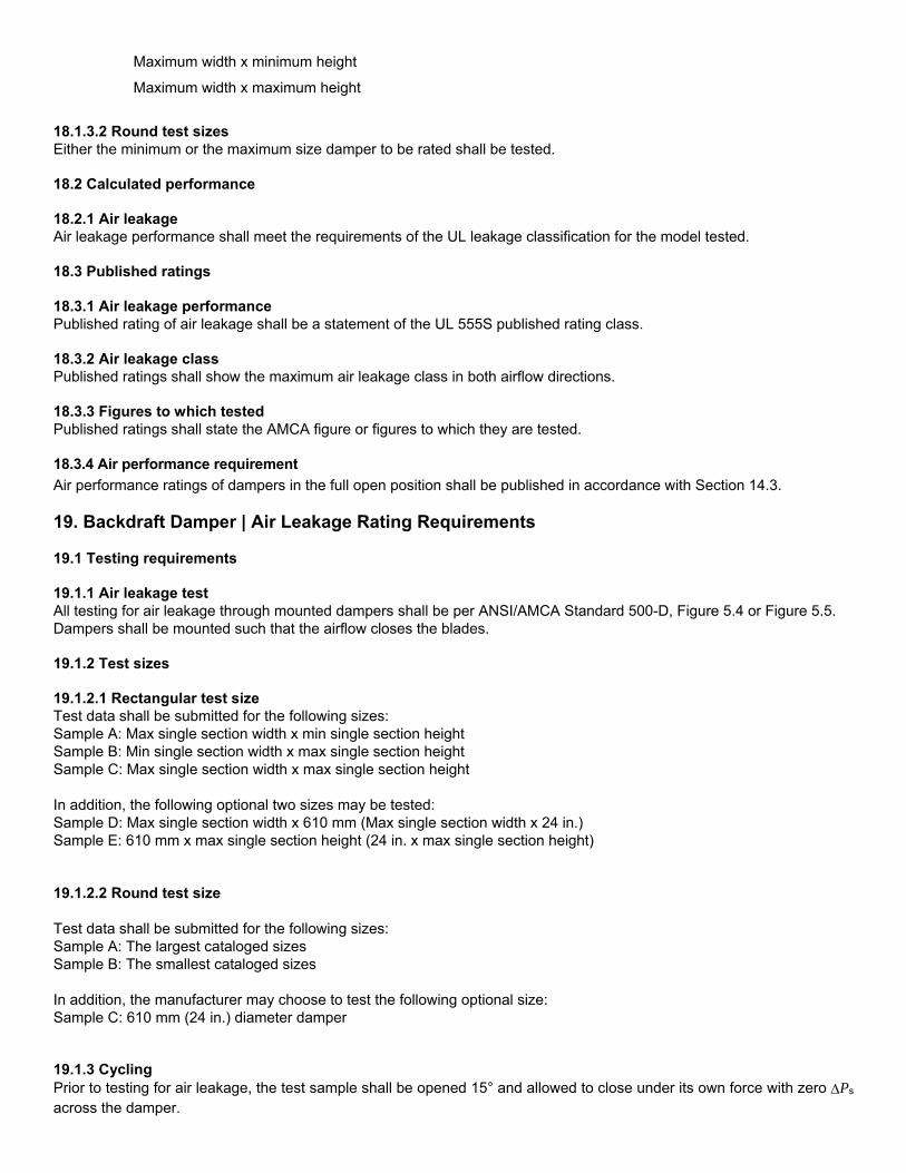
18.1.3.2 Round test sizes Either the minimum or the maximum size damper to be rated shall be tested. 18.2 Calculated performance 18.2.1 Air leakage Air leakage performance shall meet the requirements of the UL leakage classification for the model tested. 18.3 Published ratings 18.3.1 Air leakage performance Published rating of air leakage shall be a statement of the UL 555S published rating class. 18.3.2 Air leakage class Published ratings shall show the maximum air leakage class in both airflow directions. 18.3.3 Figures to which tested Published ratings shall state the AMCA figure or figures to which they are tested. 18.3.4 Air performance requirement
Air performance ratings of dampers in the full open position shall be published in accordance with Section 14.3. 19. Backdraft Damper | Air Leakage Rating Requirements 19.1 Testing requirements 19.1.1 Air leakage test All testing for air leakage through mounted dampers shall be per ANSI/AMCA Standard 500-D, Figure 5.4 or Figure 5.5. Dampers shall be mounted such that the airflow closes the blades. 19.1.2 Test sizes 19.1.2.1 Rectangular test size Test data shall be submitted for the following sizes: Sample A: Max single section width x min single section height Sample B: Min single section width x max single section height Sample C: Max single section width x max single section height In addition, the following optional two sizes may be tested: Sample D: Max single section width x 610 mm (Max single section width x 24 in.) Sample E: 610 mm x max single section height (24 in. x max single section height) 19.1.2.2 Round test size Test data shall be submitted for the following sizes: Sample A: The largest cataloged sizes Sample B: The smallest cataloged sizes In addition, the manufacturer may choose to test the following optional size: Sample C: 610 mm (24 in.) diameter damper 19.1.3 Cycling Prior to testing for air leakage, the test sample shall be opened 15° and allowed to close under its own force with zero Ps across the damper.

19.1.4 Test pressure The testing shall be conducted from the lowest rated differential pressure up to the highest. 19.1.5 Number of tests Two tests shall be conducted on each sample. Each test shall be conducted over a range of pressures consisting of at least five points. Between each test, the damper shall be opened 15° and allowed to close under its own force with zero ΔPs across the damper. If a motor is used, the damper shall be cycled from its full open to its full closed position between tests. 19.2 Calculated performance 19.2.1 Air leakage Air leakage performance at each ΔPs shall be the maximum L/s/m2 (cfm/ft2) of two tests conducted. 19.2.2 Extrapolation 19.2.2.1 Pressure Extrapolation above the maximum test ΔPs or below the minimum ΔPs shall not be permitted. 19.2.2.2 Test size Extrapolation outside the test size shall not be permitted. 19.3 Published ratings 19.3.1 Air leakage performance Published ratings of air leakage performance shall be presented as a statement of the maximum tested air leakage at the following: • A specified differential pressure • Standard air density • AMCA figure or figures to which air leakage performance is tested If only the required sizes from section 19.1.2 were tested a single L /s*m2 (cfm/ft^2) value shall be published at each differential pressure. The L /s*m2 (cfm/ft^2) value shall be the maximum of the tested sizes. If the optional size(s) from section 19.1.2 were tested a second L /s*m2 (cfm/ft^2) value may be published at each differential pressure. The first published L /s*m2 (cfm/ft^2) value shall be the maximum tested value from samples C, D and E (or A and C for round dampers). The second published L /s*m2 (cfm/ft^2) value shall be the maximum test value from samples A and B (or sample B for round dampers). 19.3.2 Test setup Published data shall show the test figure and airflow direction used during testing. 19.3.3 Operational statement Published data shall state: “Air leakage is based on operation between 0 °C - 49 °C (32 °F - 120 °F).” 19.3.4 Air performance requirement
To publish air leakage ratings, air performance ratings of the test sample defined in Section 19.1.2 only shall be tested and published in accordance with Section 14. 20. Gravity Ventilator (Excluding Louver Penthouses) | Air Performance Rating Requirements
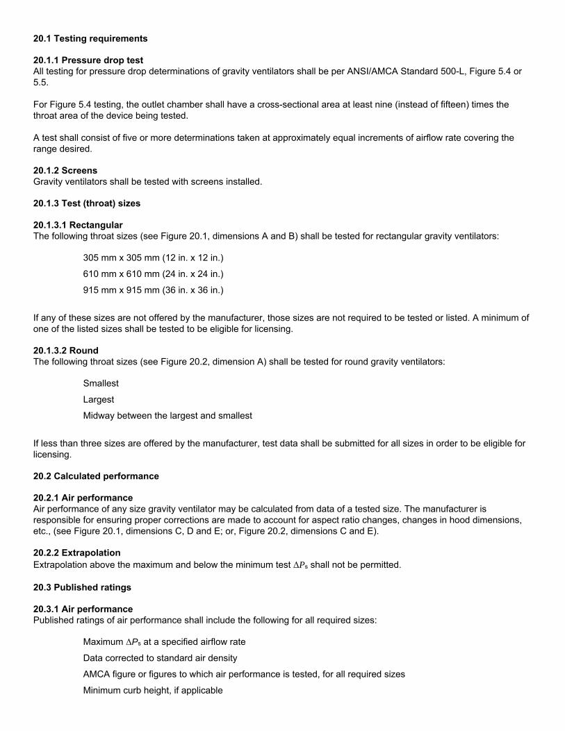
20.1 Testing requirements 20.1.1 Pressure drop test All testing for pressure drop determinations of gravity ventilators shall be per ANSI/AMCA Standard 500-L, Figure 5.4 or 5.5. For Figure 5.4 testing, the outlet chamber shall have a cross-sectional area at least nine (instead of fifteen) times the throat area of the device being tested. A test shall consist of five or more determinations taken at approximately equal increments of airflow rate covering the range desired. 20.1.2 Screens Gravity ventilators shall be tested with screens installed. 20.1.3 Test (throat) sizes 20.1.3.1 Rectangular The following throat sizes (see Figure 20.1, dimensions A and B) shall be tested for rectangular gravity ventilators:
305 mm x 305 mm (12 in. x 12 in.)
610 mm x 610 mm (24 in. x 24 in.)
915 mm x 915 mm (36 in. x 36 in.)
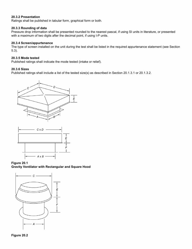
If any of these sizes are not offered by the manufacturer, those sizes are not required to be tested or listed. A minimum of one of the listed sizes shall be tested to be eligible for licensing. 20.1.3.2 Round The following throat sizes (see Figure 20.2, dimension A) shall be tested for round gravity ventilators:
Smallest
Largest
Midway between the largest and smallest
If less than three sizes are offered by the manufacturer, test data shall be submitted for all sizes in order to be eligible for licensing. 20.2 Calculated performance 20.2.1 Air performance Air performance of any size gravity ventilator may be calculated from data of a tested size. The manufacturer is responsible for ensuring proper corrections are made to account for aspect ratio changes, changes in hood dimensions, etc., (see Figure 20.1, dimensions C, D and E; or, Figure 20.2, dimensions C and E). 20.2.2 Extrapolation Extrapolation above the maximum and below the minimum test ΔPs shall not be permitted. 20.3 Published ratings 20.3.1 Air performance Published ratings of air performance shall include the following for all required sizes:
Maximum ΔPs at a specified airflow rate
Data corrected to standard air density
AMCA figure or figures to which air performance is tested, for all required sizes
Minimum curb height, if applicable
20.3.2 Presentation Ratings shall be published in tabular form, graphical form or both. 20.3.3 Rounding of data Pressure drop information shall be presented rounded to the nearest pascal, if using SI units in literature, or presented with a maximum of two digits after the decimal point, if using I-P units. 20.3.4 Screen/appurtenance The type of screen installed on the unit during the test shall be listed in the required appurtenance statement (see Section 5.3). 20.3.5 Mode tested Published ratings shall indicate the mode tested (intake or relief). 20.3.6 Sizes Published ratings shall include a list of the tested size(s) as described in Section 20.1.3.1 or 20.1.3.2.
Figure 20.1 Gravity Ventilator with Rectangular and Square Hood
Figure 20.2

Gravity Ventilator with Round Hood 21. Round Spiral Duct | Air Leakage Rating Requirements 21.1 Testing requirements 21.1.1 Air leakage test All spiral duct air leakage testing shall be conducted in accordance with ANSI/ASHRAE/SMACNA Standard 126-2008, Section 7. 21.1.2 Bubble test A bubble test shall be conducted in accordance with ANSI/AMCA Standard 500-D prior to the air leakage test to ensure there is no endcap leakage. 21.1.3 Test pressure Testing shall be performed at 1.5 times the normal maximum design pressure of 2.5 kPa (10 in. wg). 21.1.4 Test sample The test sample shall be a 600 mm (24 in.) diameter by 3000 mm (120 in.) long section of spiral duct. The ends shall be capped and sealed by the manufacturer and one endcap shall also contain two DN10 (3/8 in.) pipe size barb fittings. Testing shall include ducts of the following gauges: 28, 26, 24, 22, 20, 18, 16, 14. If the manufacturer does not produce all of the required gauges, testing shall include all gauges that a manufacturer produces. 21.2 Calculated performance 21.2.1 Data correction Air leakage performance shall be corrected from actual conditions to standard conditions using the equations shown in ANSI/ASHRAE/SMACNA Standard 126-2008, Section 7.4. 21.2.2 Data conversion The calculated air leakage performance in m3/hr (cfm) shall be converted to m3/hr per 9.29 m2 (cfm per 100 ft2) of duct wall surface. 21.3 Published ratings 21.3.1 Air leakage performance Published rating of air leakage performance shall be a statement of the maximum tested air leakage flow rate for each gauge at 3.75 kPa (15 in. wg) ΔPs in m3/hr per 9.29 m2 (cfm per 100 ft2) of duct wall surface area at standard air density. 21.3.2 Test sample information Published data shall include the following test sample information:
Length
Gauge
Diameter
21.3.3 Certified gauges All gauges of spiral duct published in a catalog shall be certified. 22. Louver/Damper | Energy Efficiency Rating Requirements 22.1 Testing requirements
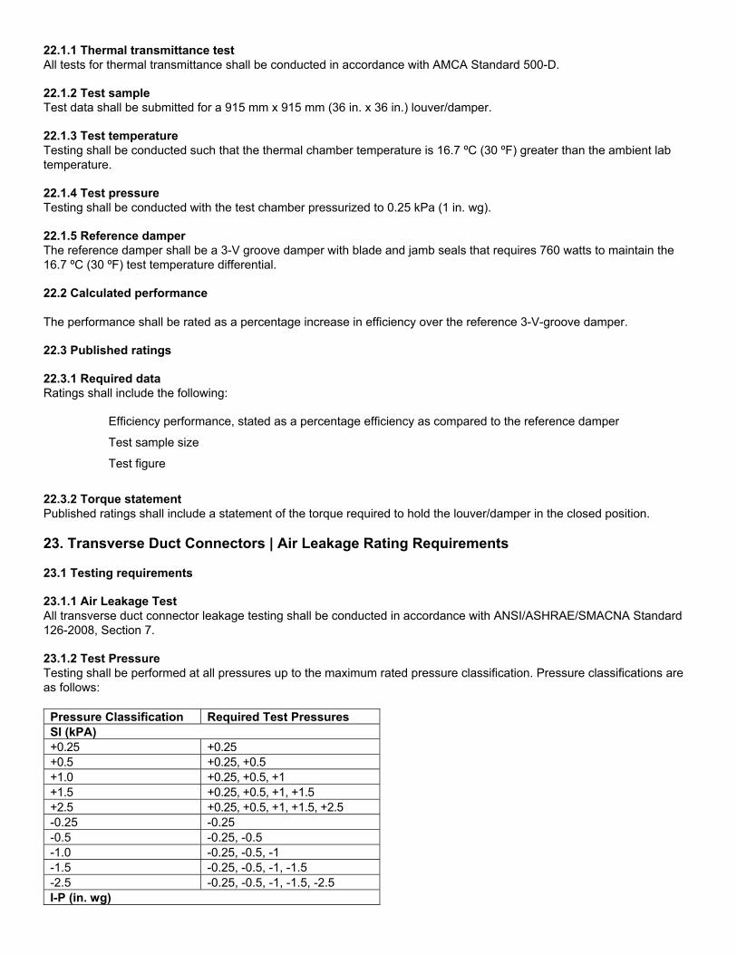
22.1.1 Thermal transmittance test All tests for thermal transmittance shall be conducted in accordance with AMCA Standard 500-D. 22.1.2 Test sample Test data shall be submitted for a 915 mm x 915 mm (36 in. x 36 in.) louver/damper. 22.1.3 Test temperature Testing shall be conducted such that the thermal chamber temperature is 16.7 ºC (30 ºF) greater than the ambient lab temperature. 22.1.4 Test pressure Testing shall be conducted with the test chamber pressurized to 0.25 kPa (1 in. wg). 22.1.5 Reference damper The reference damper shall be a 3-V groove damper with blade and jamb seals that requires 760 watts to maintain the 16.7 ºC (30 ºF) test temperature differential. 22.2 Calculated performance The performance shall be rated as a percentage increase in efficiency over the reference 3-V-groove damper. 22.3 Published ratings 22.3.1 Required data Ratings shall include the following:
Efficiency performance, stated as a percentage efficiency as compared to the reference damper
Test sample size
Test figure
22.3.2 Torque statement Published ratings shall include a statement of the torque required to hold the louver/damper in the closed position. 23. Transverse Duct Connectors | Air Leakage Rating Requirements 23.1 Testing requirements 23.1.1 Air Leakage Test All transverse duct connector leakage testing shall be conducted in accordance with ANSI/ASHRAE/SMACNA Standard 126-2008, Section 7. 23.1.2 Test Pressure Testing shall be performed at all pressures up to the maximum rated pressure classification. Pressure classifications are as follows:
Pressure Classification Required Test Pressures SI (kPA) +0.25 +0.25 +0.5 +0.25, +0.5 +1.0 +0.25, +0.5, +1 +1.5 +0.25, +0.5, +1, +1.5 +2.5 +0.25, +0.5, +1, +1.5, +2.5 -0.25 -0.25 -0.5 -0.25, -0.5 -1.0 -0.25, -0.5, -1 -1.5 -0.25, -0.5, -1, -1.5 -2.5 -0.25, -0.5, -1, -1.5, -2.5 I-P (in. wg)
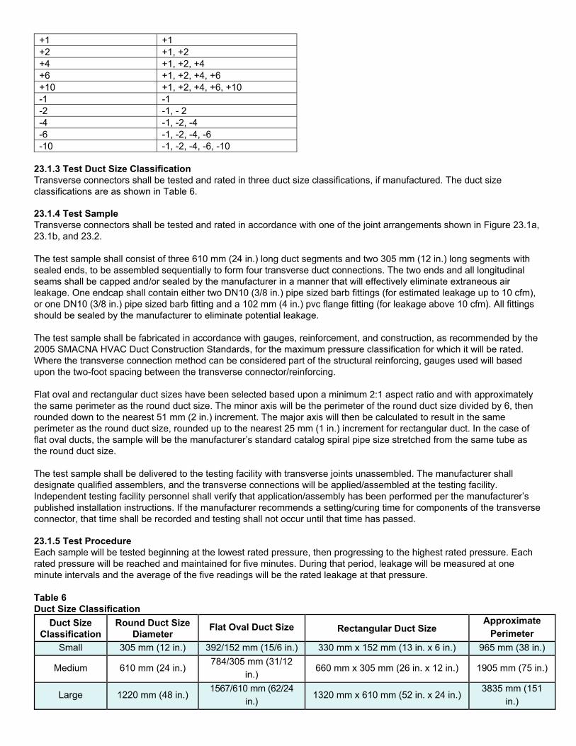
+1 +1 +2 +1, +2 +4 +1, +2, +4 +6 +1, +2, +4, +6 +10 +1, +2, +4, +6, +10 -1 -1 -2 -1, - 2 -4 -1, -2, -4 -6 -1, -2, -4, -6 -10 -1, -2, -4, -6, -10
23.1.3 Test Duct Size Classification Transverse connectors shall be tested and rated in three duct size classifications, if manufactured. The duct size classifications are as shown in Table 6. 23.1.4 Test Sample Transverse connectors shall be tested and rated in accordance with one of the joint arrangements shown in Figure 23.1a, 23.1b, and 23.2. The test sample shall consist of three 610 mm (24 in.) long duct segments and two 305 mm (12 in.) long segments with sealed ends, to be assembled sequentially to form four transverse duct connections. The two ends and all longitudinal seams shall be capped and/or sealed by the manufacturer in a manner that will effectively eliminate extraneous air leakage. One endcap shall contain either two DN10 (3/8 in.) pipe sized barb fittings (for estimated leakage up to 10 cfm), or one DN10 (3/8 in.) pipe sized barb fitting and a 102 mm (4 in.) pvc flange fitting (for leakage above 10 cfm). All fittings should be sealed by the manufacturer to eliminate potential leakage. The test sample shall be fabricated in accordance with gauges, reinforcement, and construction, as recommended by the 2005 SMACNA HVAC Duct Construction Standards, for the maximum pressure classification for which it will be rated. Where the transverse connection method can be considered part of the structural reinforcing, gauges used will based upon the two-foot spacing between the transverse connector/reinforcing. Flat oval and rectangular duct sizes have been selected based upon a minimum 2:1 aspect ratio and with approximately the same perimeter as the round duct size. The minor axis will be the perimeter of the round duct size divided by 6, then rounded down to the nearest 51 mm (2 in.) increment. The major axis will then be calculated to result in the same perimeter as the round duct size, rounded up to the nearest 25 mm (1 in.) increment for rectangular duct. In the case of flat oval ducts, the sample will be the manufacturer’s standard catalog spiral pipe size stretched from the same tube as the round duct size. The test sample shall be delivered to the testing facility with transverse joints unassembled. The manufacturer shall designate qualified assemblers, and the transverse connections will be applied/assembled at the testing facility. Independent testing facility personnel shall verify that application/assembly has been performed per the manufacturer’s published installation instructions. If the manufacturer recommends a setting/curing time for components of the transverse connector, that time shall be recorded and testing shall not occur until that time has passed. 23.1.5 Test Procedure Each sample will be tested beginning at the lowest rated pressure, then progressing to the highest rated pressure. Each rated pressure will be reached and maintained for five minutes. During that period, leakage will be measured at one minute intervals and the average of the five readings will be the rated leakage at that pressure. Table 6 Duct Size Classification
Duct Size Classification
Round Duct Size Diameter
Flat Oval Duct Size Rectangular Duct Size Approximate
Perimeter
Small 305 mm (12 in.) 392/152 mm (15/6 in.) 330 mm x 152 mm (13 in. x 6 in.) 965 mm (38 in.)
Medium 610 mm (24 in.) 784/305 mm (31/12
in.) 660 mm x 305 mm (26 in. x 12 in.) 1905 mm (75 in.)
Large 1220 mm (48 in.) 1567/610 mm (62/24
in.) 1320 mm x 610 mm (52 in. x 24 in.)
3835 mm (151 in.)
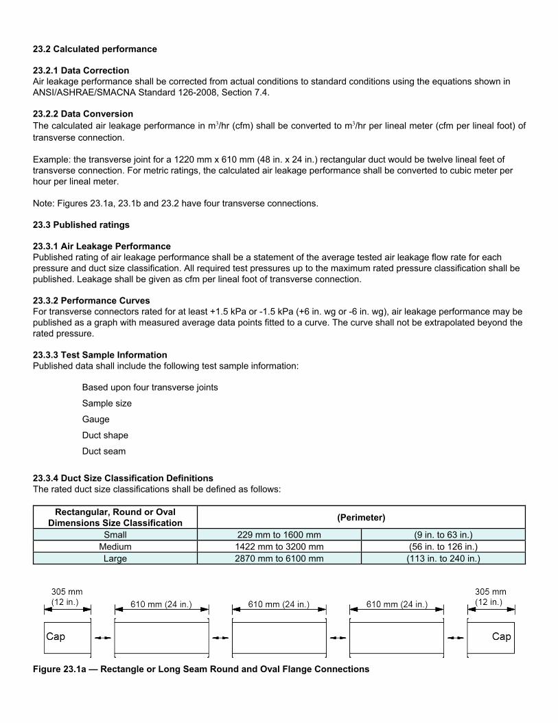
23.2 Calculated performance 23.2.1 Data Correction Air leakage performance shall be corrected from actual conditions to standard conditions using the equations shown in ANSI/ASHRAE/SMACNA Standard 126-2008, Section 7.4. 23.2.2 Data Conversion The calculated air leakage performance in m3/hr (cfm) shall be converted to m3/hr per lineal meter (cfm per lineal foot) of transverse connection. Example: the transverse joint for a 1220 mm x 610 mm (48 in. x 24 in.) rectangular duct would be twelve lineal feet of transverse connection. For metric ratings, the calculated air leakage performance shall be converted to cubic meter per hour per lineal meter. Note: Figures 23.1a, 23.1b and 23.2 have four transverse connections. 23.3 Published ratings 23.3.1 Air Leakage Performance Published rating of air leakage performance shall be a statement of the average tested air leakage flow rate for each pressure and duct size classification. All required test pressures up to the maximum rated pressure classification shall be published. Leakage shall be given as cfm per lineal foot of transverse connection. 23.3.2 Performance Curves For transverse connectors rated for at least +1.5 kPa or -1.5 kPa (+6 in. wg or -6 in. wg), air leakage performance may be published as a graph with measured average data points fitted to a curve. The curve shall not be extrapolated beyond the rated pressure. 23.3.3 Test Sample Information Published data shall include the following test sample information:
Based upon four transverse joints
Sample size
Gauge
Duct shape
Duct seam
23.3.4 Duct Size Classification Definitions The rated duct size classifications shall be defined as follows:
Rectangular, Round or Oval Dimensions Size Classification
(Perimeter)
Small 229 mm to 1600 mm (9 in. to 63 in.) Medium 1422 mm to 3200 mm (56 in. to 126 in.) Large 2870 mm to 6100 mm (113 in. to 240 in.)
Figure 23.1a — Rectangle or Long Seam Round and Oval Flange Connections
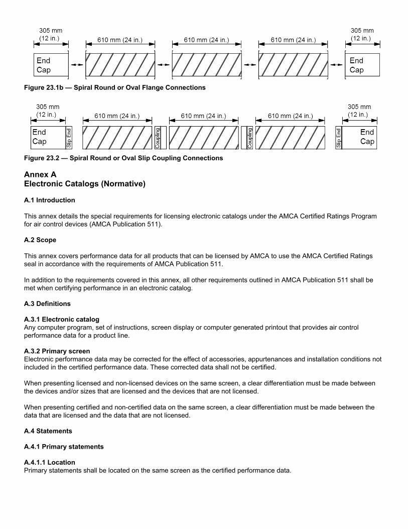
Figure 23.1b — Spiral Round or Oval Flange Connections
Figure 23.2 — Spiral Round or Oval Slip Coupling Connections Annex A Electronic Catalogs (Normative) A.1 Introduction This annex details the special requirements for licensing electronic catalogs under the AMCA Certified Ratings Program for air control devices (AMCA Publication 511). A.2 Scope This annex covers performance data for all products that can be licensed by AMCA to use the AMCA Certified Ratings seal in accordance with the requirements of AMCA Publication 511. In addition to the requirements covered in this annex, all other requirements outlined in AMCA Publication 511 shall be met when certifying performance in an electronic catalog. A.3 Definitions A.3.1 Electronic catalog Any computer program, set of instructions, screen display or computer generated printout that provides air control performance data for a product line. A.3.2 Primary screen Electronic performance data may be corrected for the effect of accessories, appurtenances and installation conditions not included in the certified performance data. These corrected data shall not be certified. When presenting licensed and non-licensed devices on the same screen, a clear differentiation must be made between the devices and/or sizes that are licensed and the devices that are not licensed. When presenting certified and non-certified data on the same screen, a clear differentiation must be made between the data that are licensed and the data that are not licensed. A.4 Statements A.4.1 Primary statements A.4.1.1 Location Primary statements shall be located on the same screen as the certified performance data.
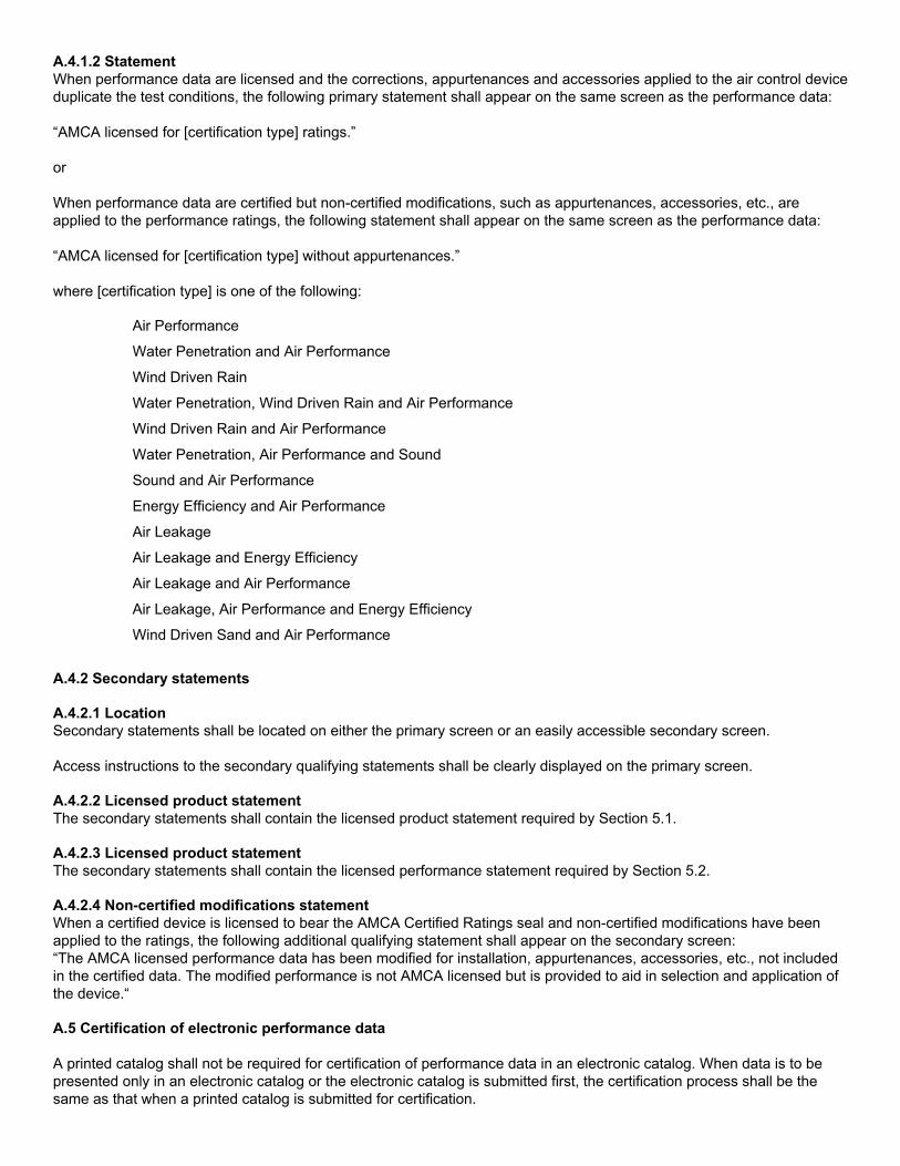
A.4.1.2 Statement When performance data are licensed and the corrections, appurtenances and accessories applied to the air control device duplicate the test conditions, the following primary statement shall appear on the same screen as the performance data: “AMCA licensed for [certification type] ratings.” or When performance data are certified but non-certified modifications, such as appurtenances, accessories, etc., are applied to the performance ratings, the following statement shall appear on the same screen as the performance data: “AMCA licensed for [certification type] without appurtenances.” where [certification type] is one of the following:
Air Performance
Water Penetration and Air Performance
Wind Driven Rain
Water Penetration, Wind Driven Rain and Air Performance
Wind Driven Rain and Air Performance
Water Penetration, Air Performance and Sound
Sound and Air Performance
Energy Efficiency and Air Performance
Air Leakage
Air Leakage and Energy Efficiency
Air Leakage and Air Performance
Air Leakage, Air Performance and Energy Efficiency
Wind Driven Sand and Air Performance
A.4.2 Secondary statements A.4.2.1 Location Secondary statements shall be located on either the primary screen or an easily accessible secondary screen. Access instructions to the secondary qualifying statements shall be clearly displayed on the primary screen. A.4.2.2 Licensed product statement The secondary statements shall contain the licensed product statement required by Section 5.1. A.4.2.3 Licensed product statement The secondary statements shall contain the licensed performance statement required by Section 5.2. A.4.2.4 Non-certified modifications statement When a certified device is licensed to bear the AMCA Certified Ratings seal and non-certified modifications have been applied to the ratings, the following additional qualifying statement shall appear on the secondary screen: “The AMCA licensed performance data has been modified for installation, appurtenances, accessories, etc., not included in the certified data. The modified performance is not AMCA licensed but is provided to aid in selection and application of the device.“ A.5 Certification of electronic performance data A printed catalog shall not be required for certification of performance data in an electronic catalog. When data is to be presented only in an electronic catalog or the electronic catalog is submitted first, the certification process shall be the same as that when a printed catalog is submitted for certification.

When a previously certified printed catalog exists, it shall be considered primary. A.6 Version numbers All electronic catalogs which contain certified data shall include a unique version number and date. Both the version number and date shall be visible on the distribution medium and the first screen of the electronic catalog. The date shall be in the following notation: e.g.,“January 20XX.” In the event that the certification status of any product within an electronic catalog changes, a new version of the electronic catalog shall be produced with an identifiable change in the version number. A.7 Certified performance identification Electronic catalogs shall provide a product directory which includes all products contained within the electronic catalog. Each product in the directory shall be clearly identified as either AMCA licensed or not AMCA licensed. Instructions for accessing the AMCA product directory shall be included in an easily identifiable manner. A.8 AMCA directory listings Electronic catalogs containing certified data shall be listed in the AMCA Directory of Licensed Products. Annex B Measurements (Normative)
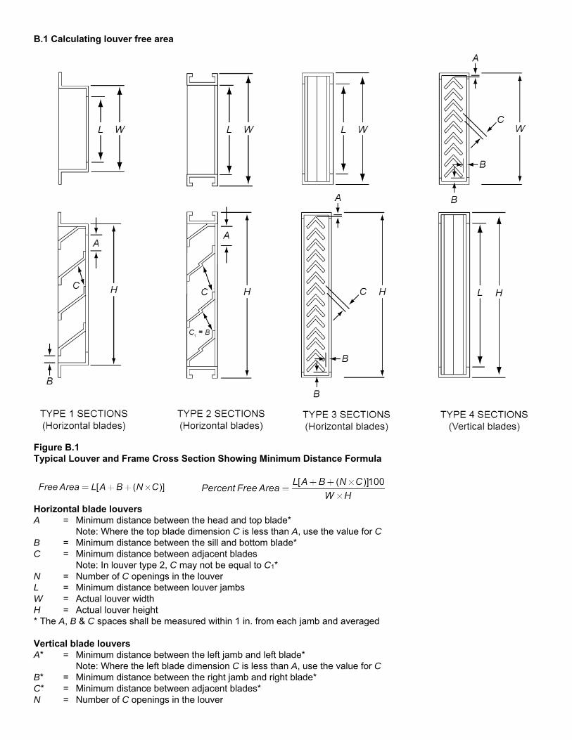
B.1 Calculating louver free area
Figure B.1 Typical Louver and Frame Cross Section Showing Minimum Distance Formula
Horizontal blade louvers A = Minimum distance between the head and top blade* Note: Where the top blade dimension C is less than A, use the value for C B = Minimum distance between the sill and bottom blade* C = Minimum distance between adjacent blades Note: In louver type 2, C may not be equal to C1* N = Number of C openings in the louver L = Minimum distance between louver jambs W = Actual louver width H = Actual louver height * The A, B & C spaces shall be measured within 1 in. from each jamb and averaged Vertical blade louvers A* = Minimum distance between the left jamb and left blade* Note: Where the left blade dimension C is less than A, use the value for C B* = Minimum distance between the right jamb and right blade* C* = Minimum distance between adjacent blades* N = Number of C openings in the louver
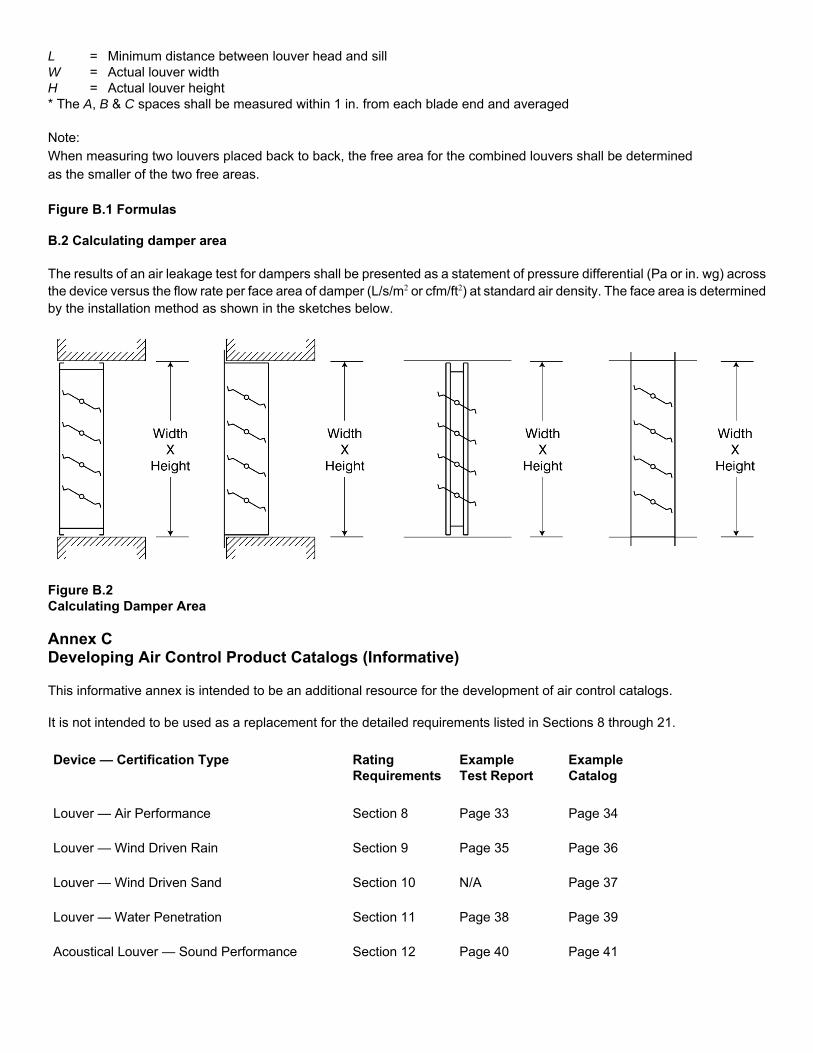
L = Minimum distance between louver head and sill W = Actual louver width H = Actual louver height * The A, B & C spaces shall be measured within 1 in. from each blade end and averaged Note: When measuring two louvers placed back to back, the free area for the combined louvers shall be determined as the smaller of the two free areas.
Figure B.1 Formulas B.2 Calculating damper area The results of an air leakage test for dampers shall be presented as a statement of pressure differential (Pa or in. wg) across the device versus the flow rate per face area of damper (L/s/m2 or cfm/ft2) at standard air density. The face area is determined by the installation method as shown in the sketches below.
Figure B.2 Calculating Damper Area Annex C Developing Air Control Product Catalogs (Informative) This informative annex is intended to be an additional resource for the development of air control catalogs. It is not intended to be used as a replacement for the detailed requirements listed in Sections 8 through 21.
Device — Certification Type Rating Requirements
Example Test Report
Example Catalog
Louver — Air Performance Section 8 Page 33 Page 34
Louver — Wind Driven Rain Section 9 Page 35 Page 36
Louver — Wind Driven Sand Section 10 N/A Page 37
Louver — Water Penetration Section 11 Page 38 Page 39
Acoustical Louver — Sound Performance Section 12 Page 40 Page 41
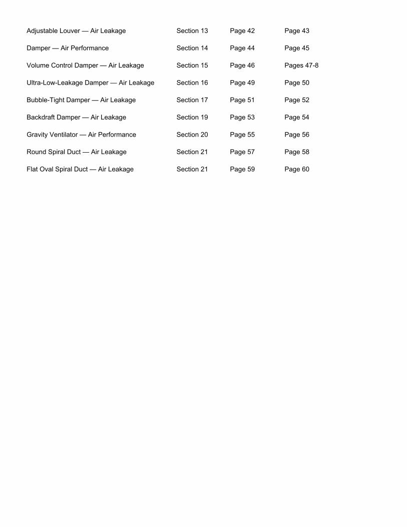
Adjustable Louver — Air Leakage Section 13 Page 42 Page 43
Damper — Air Performance Section 14 Page 44 Page 45
Volume Control Damper — Air Leakage Section 15 Page 46 Pages 47-8
Ultra-Low-Leakage Damper — Air Leakage Section 16 Page 49 Page 50
Bubble-Tight Damper — Air Leakage Section 17 Page 51 Page 52
Backdraft Damper — Air Leakage Section 19 Page 53 Page 54
Gravity Ventilator — Air Performance Section 20 Page 55 Page 56
Round Spiral Duct — Air Leakage Section 21 Page 57 Page 58
Flat Oval Spiral Duct — Air Leakage Section 21 Page 59 Page 60
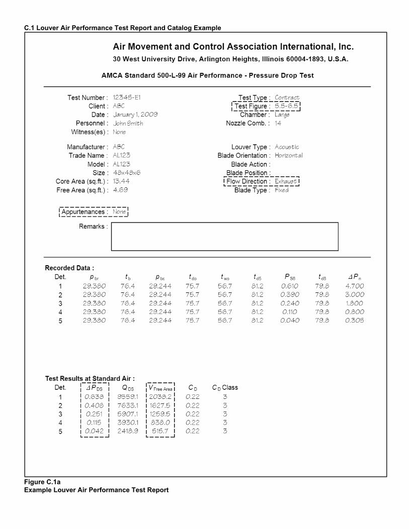
C.1 Louver Air Performance Test Report and Catalog Example
Figure C.1a Example Louver Air Performance Test Report
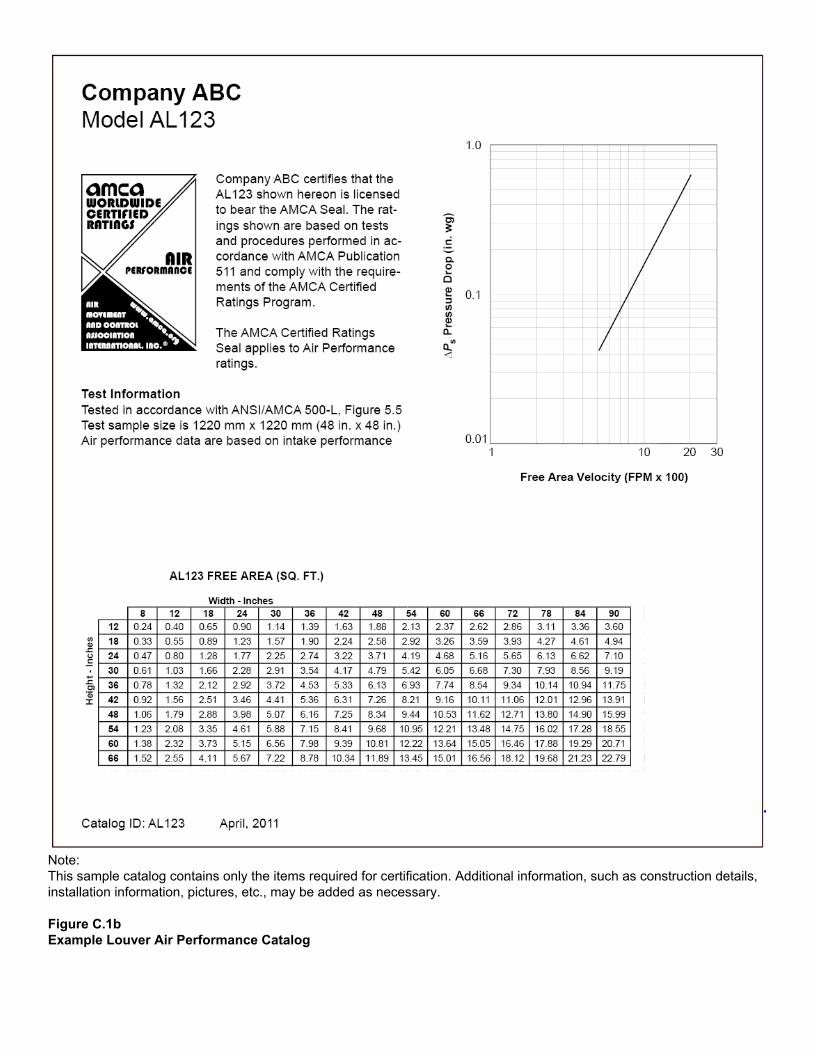
Note: This sample catalog contains only the items required for certification. Additional information, such as construction details, installation information, pictures, etc., may be added as necessary. Figure C.1b Example Louver Air Performance Catalog
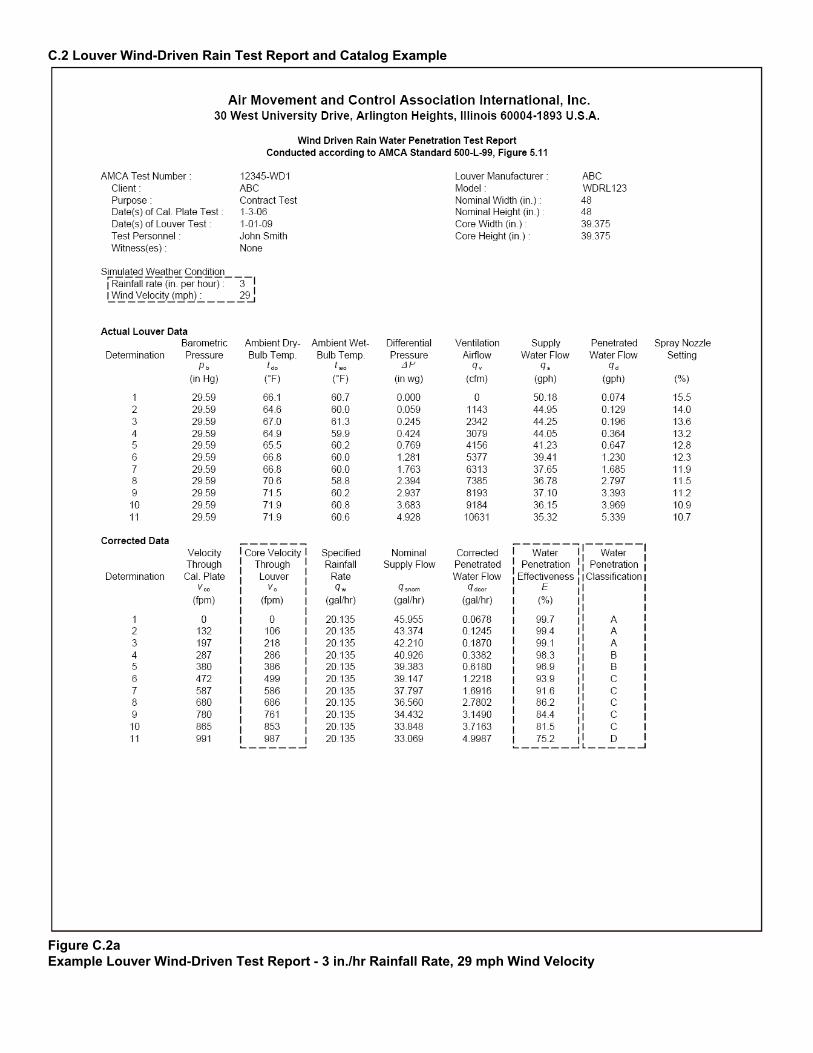
C.2 Louver Wind-Driven Rain Test Report and Catalog Example
Figure C.2a Example Louver Wind-Driven Test Report - 3 in./hr Rainfall Rate, 29 mph Wind Velocity
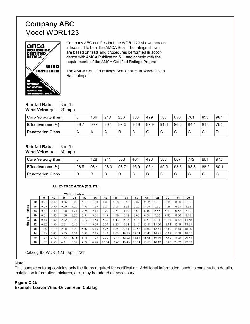
Note: This sample catalog contains only the items required for certification. Additional information, such as construction details, installation information, pictures, etc., may be added as necessary. Figure C.2b Example Louver Wind-Driven Rain Catalog
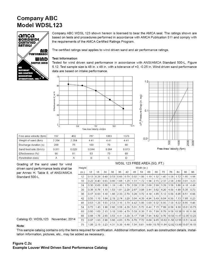
Figure C.2c Example Louver Wind Driven Sand Performance Catalog
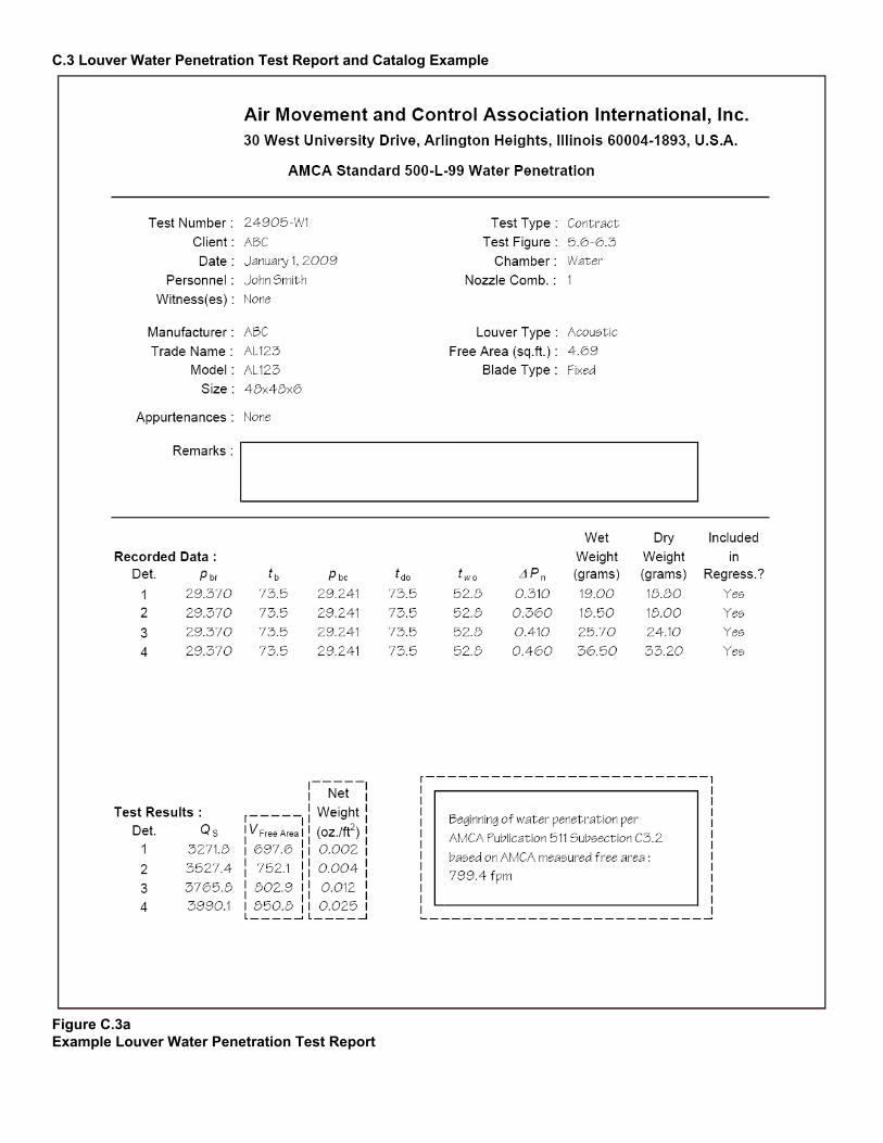
C.3 Louver Water Penetration Test Report and Catalog Example
Figure C.3a Example Louver Water Penetration Test Report

Note: This sample catalog contains only the items required for certification. Additional information, such as construction details, installation information, pictures, etc., may be added as necessary. Figure C.3b Example Louver Water Penetration Catalog
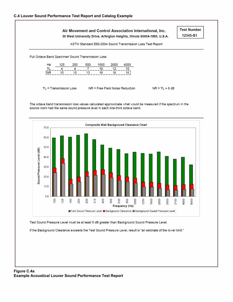
C.4 Louver Sound Performance Test Report and Catalog Example
Figure C.4a Example Acoustical Louver Sound Performance Test Report
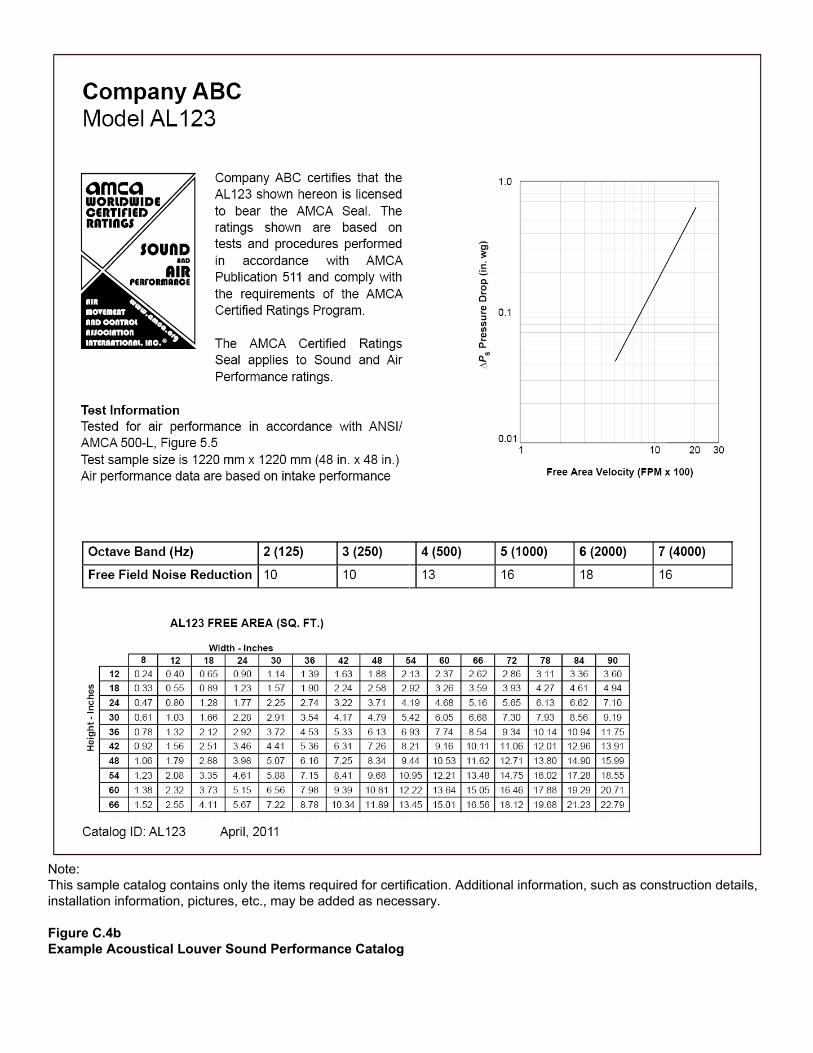
Note: This sample catalog contains only the items required for certification. Additional information, such as construction details, installation information, pictures, etc., may be added as necessary. Figure C.4b Example Acoustical Louver Sound Performance Catalog
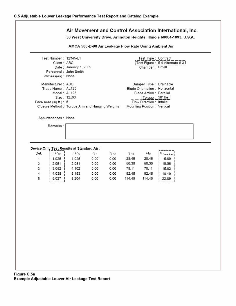
C.5 Adjustable Louver Leakage Performance Test Report and Catalog Example
Figure C.5a Example Adjustable Louver Air Leakage Test Report
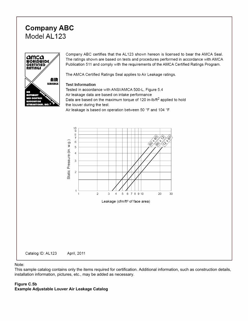
Note: This sample catalog contains only the items required for certification. Additional information, such as construction details, installation information, pictures, etc., may be added as necessary. Figure C.5b Example Adjustable Louver Air Leakage Catalog
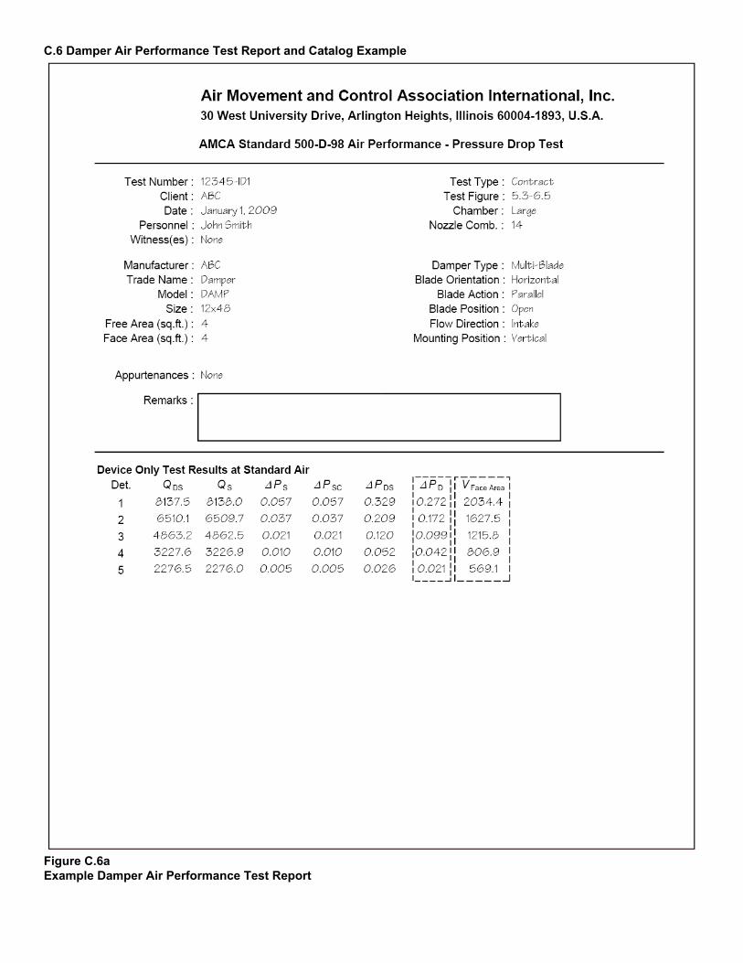
C.6 Damper Air Performance Test Report and Catalog Example
Figure C.6a Example Damper Air Performance Test Report
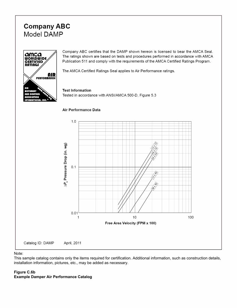
Note: This sample catalog contains only the items required for certification. Additional information, such as construction details, installation information, pictures, etc., may be added as necessary. Figure C.6b Example Damper Air Performance Catalog
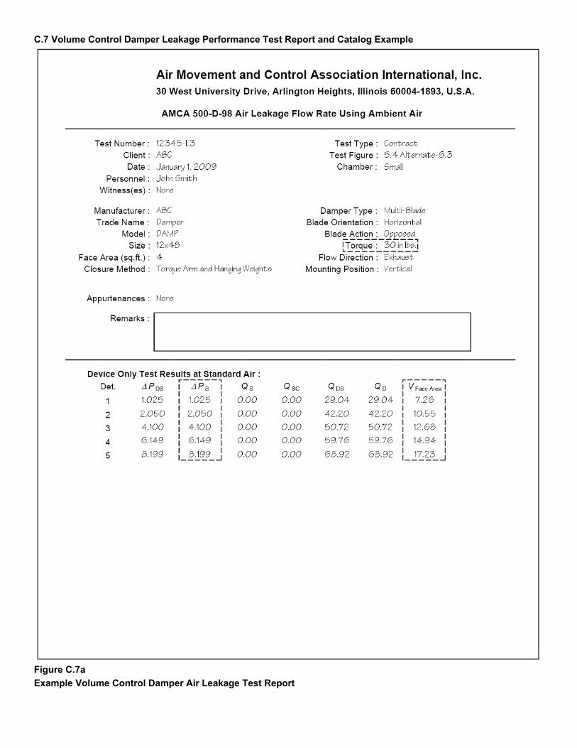
C.7 Volume Control Damper Leakage Performance Test Report and Catalog Example
Figure C.7a
Example Volume Control Damper Air Leakage Test Report

Example 1 The company certifying the leakage performance only conducted tests on the two required sizes. The maximum single section width of this model is 60 in. Because only the two required sizes were tested, the catalog data does not have to distinguish the leakage performance at different widths.
Leakage Class Test Results Width x Height 1 in. wg 4 in. wg 6 in. wg 8 in. wg
12 x 48 in. 1 1 1 1
60 x 36 in. 1A 1 2 2
Example Catalog Table
Leakage Class 1 in. wg 4 in. wg 6 in. wg 8 in. wg
1 1 2 2 Example 2 The same company certifies the same damper as in Example 1. This time they test one optional size, 16 in. x 36 in., along with the two required sizes. This allows them to catalog leakage class 1A performance at 1 in. wg on dampers 16 in. and wider. Leakage Class Test Results
Width x Height 1 in. wg 4 in. wg 6 in. wg 8 in. wg
12 x 48 in. 1 1 1 1
16 x 36 in. 1A 1 1 1
60 x 36 in. 1A 1 2 2
Example Catalog Table Leakage Class
Damper Width 1 in. wg 4 in. wg 6 in. wg 8 in. wg Less than 16 in. 1 1 1 1 16 to 60 in. 1A 1 2 2
Example 3 The same company again certifies the same damper as in Example 1. This time they test two optional sizes, 16 in. x 36 in. and a 48 in. x 36 in., along with the two required sizes. This not only allows them to catalog leakage class 1A performance at 1 in. wg on dampers 16 in. and wider, but also allows them to catalog class 1 performance at up to 8 in. wg on dampers all the way up to 48 in. wide. Leakage Class Test Results
Width x Height 1 in. wg 4 in. wg 6 in. wg 8 in. wg
12 x 48 in. 1 1 1 1
16 x 36 in. 1A 1 1 1
48 x 36 in. 1A 1 1 1
60 x 36 in. 1A 1 2 2
Example Catalog Table Leakage Class
Damper Width 1 in. wg 4 in. wg 6 in. wg 8 in. wg Less than 16 in. 1 1 1 1 16 to 60 in. 1A 1 1 1 48.01 to 60 in. 1A 1 2 2
Figure C.7b Example Volume Control Damper Air Leakage Test Results and Corresponding Published Data
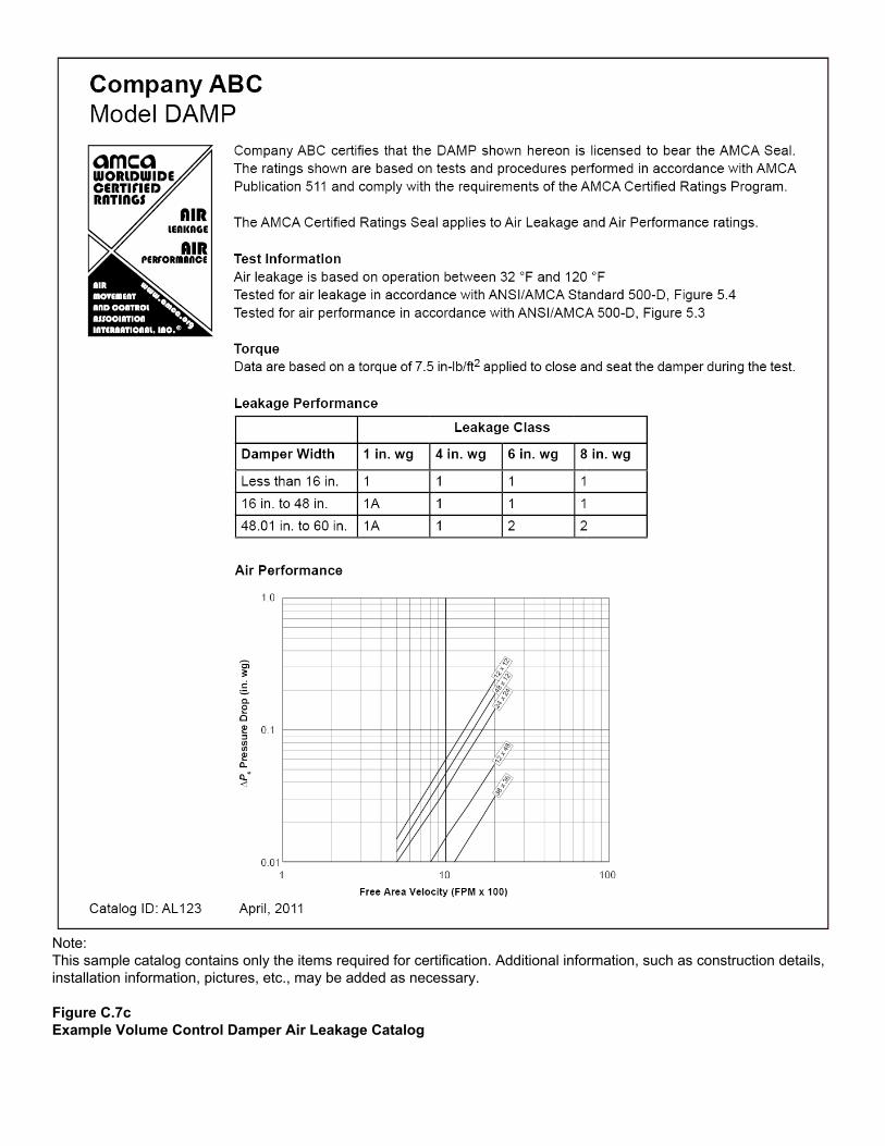
Note: This sample catalog contains only the items required for certification. Additional information, such as construction details, installation information, pictures, etc., may be added as necessary. Figure C.7c Example Volume Control Damper Air Leakage Catalog

C.8 Ultra-Low-Leakage Damper Leakage Test Report and Catalog Example
Figure C.8a Example Ultra-Low-Leakage Damper Air Leakage Test Report

Note: This sample catalog contains only the items required for certification. Additional information, such as construction details, installation information, pictures, etc., may be added as necessary. Figure C.8b Example Ultra-Low-Leakage Damper Air Leakage Catalog
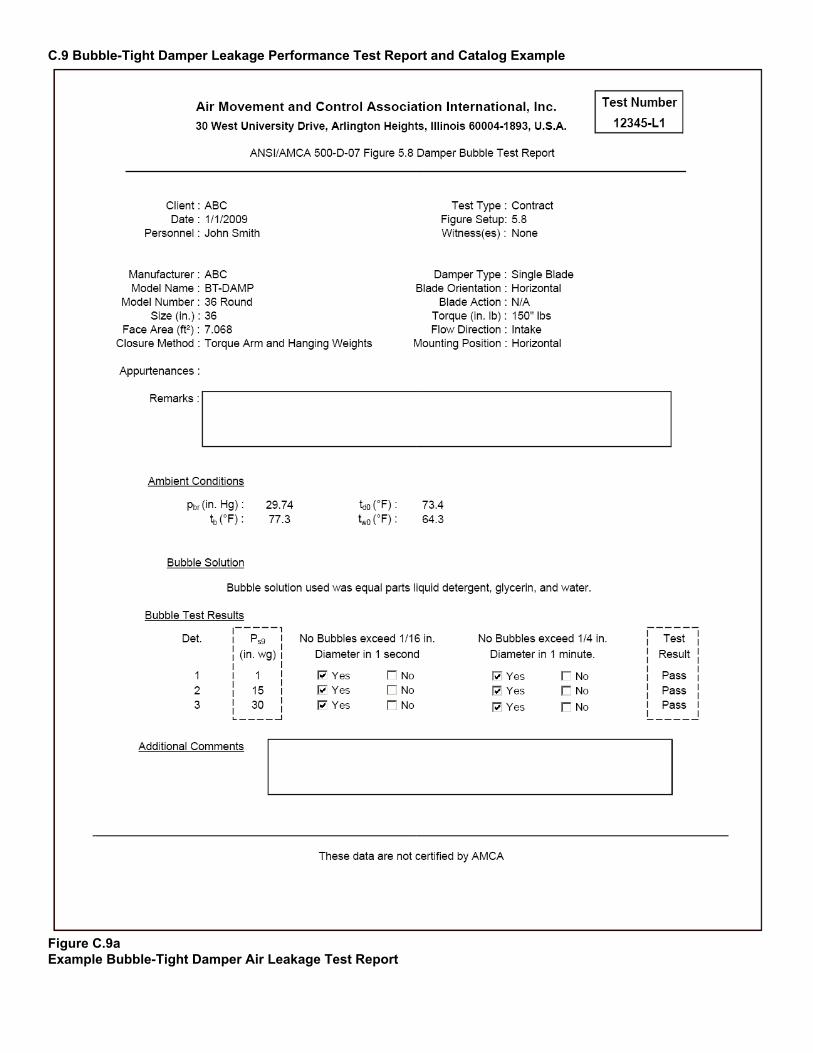
C.9 Bubble-Tight Damper Leakage Performance Test Report and Catalog Example
Figure C.9a Example Bubble-Tight Damper Air Leakage Test Report
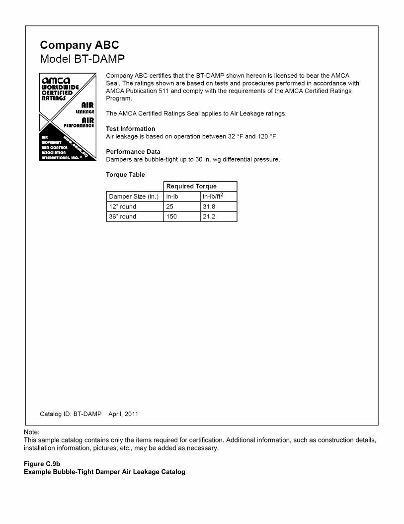
Note: This sample catalog contains only the items required for certification. Additional information, such as construction details, installation information, pictures, etc., may be added as necessary. Figure C.9b Example Bubble-Tight Damper Air Leakage Catalog

C.10 Backdraft Damper Leakage Performance Test Report and Catalog Example
Figure C.10a Example Backdraft Damper Air Leakage Test Report
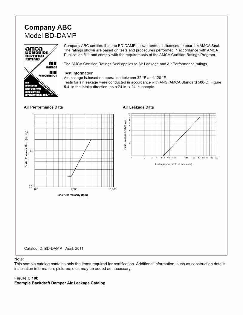
Note: This sample catalog contains only the items required for certification. Additional information, such as construction details, installation information, pictures, etc., may be added as necessary. Figure C.10b Example Backdraft Damper Air Leakage Catalog

C.11 Gravity Ventilator Air Performance Test Report and Catalog Example
Figure C.11a Example Gravity Ventilator Air Performance Test Report
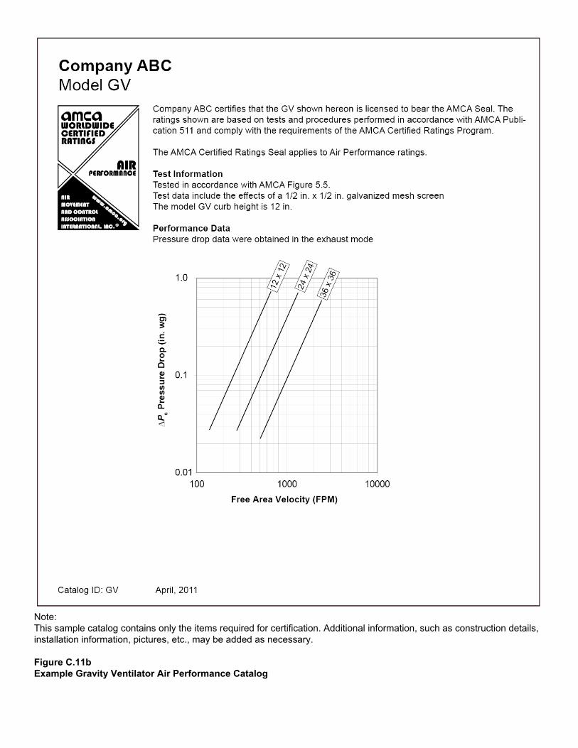
Note: This sample catalog contains only the items required for certification. Additional information, such as construction details, installation information, pictures, etc., may be added as necessary. Figure C.11b Example Gravity Ventilator Air Performance Catalog

C.12 Spiral Duct Leakage Performance Test Report and Catalog Example
Figure C.12a Example Spiral Duct Air Leakage Performance Test Report
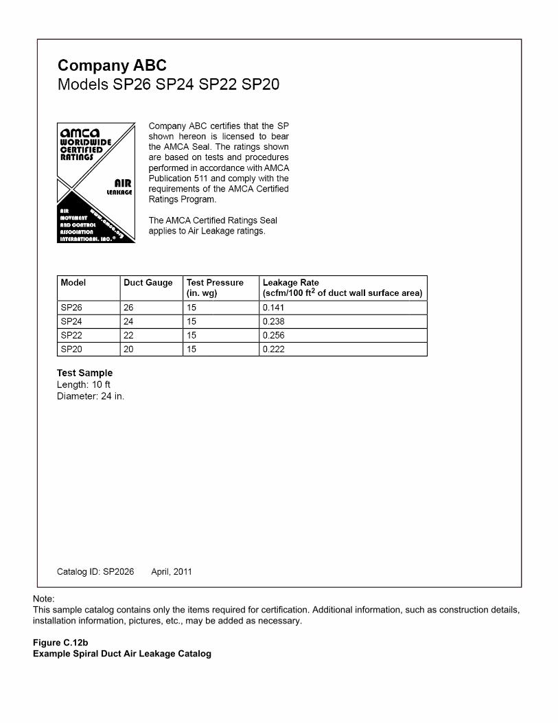
Note: This sample catalog contains only the items required for certification. Additional information, such as construction details, installation information, pictures, etc., may be added as necessary. Figure C.12b Example Spiral Duct Air Leakage Catalog

C.13 Flat Oval Spiral Duct Leakage Performance Test Report and Catalog Example
Figure C.13a
Example Flat Oval Spiral Duct Air Leakage Performance Test Report Note: This sample catalog contains only the items required for certification. Additional information, such as construction details, installation information, pictures, etc., may be added as necessary.
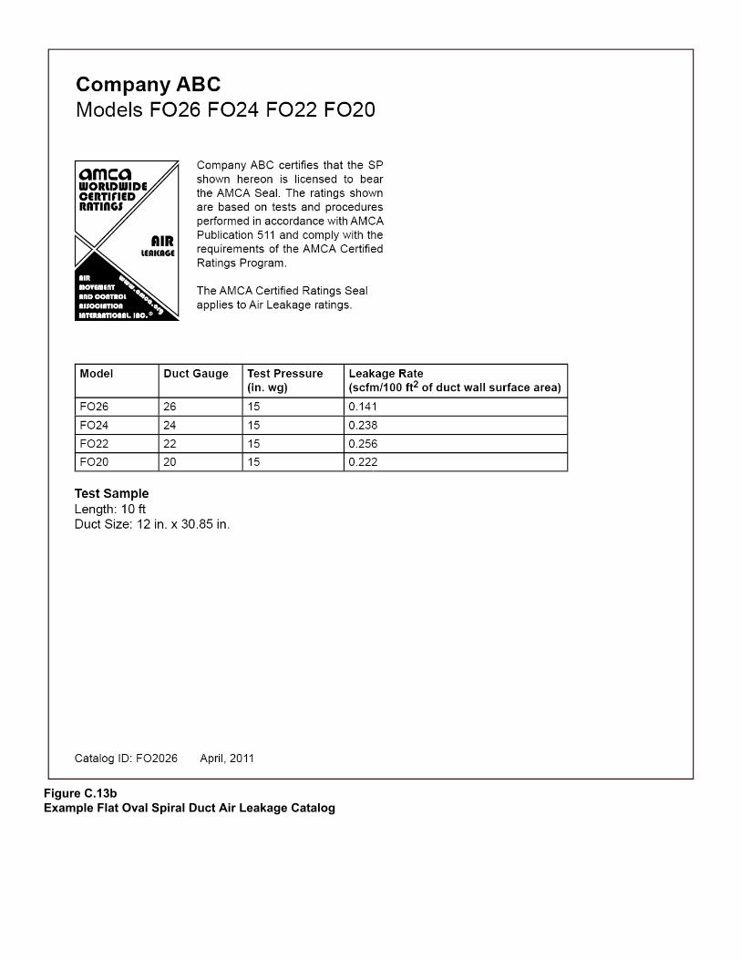
Figure C.13b Example Flat Oval Spiral Duct Air Leakage Catalog


The Air Movement and Control Association International Inc. is a not-for-profit association of the world’s manufacturers of air system equipment, such as fans, louvers, dampers, air curtains, airflow measurement stations, acoustic attenuators and other air system components for the industrial and commercial markets.
30 West University DriveArlington Heights, IL 60004-1893 U.S.
www.amca.org ■ +1 (847) 394-0150 ■ [email protected]
amca international