alsipercha system€¦ · alsipercha system assembly and safety manual v5 edición: 02/2015 code:...
TRANSCRIPT
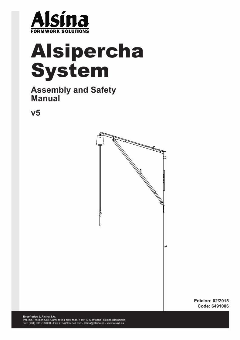
Alsipercha SystemAssembly and Safety Manualv5
Edición: 02/2015Code: 6491006
Encofrados J. Alsina S.A.Pol. Ind. Pla d’en Coll, Camí de la Font Freda, 1 08110 Montcada i Reixac (Barcelona)Tel.: (+34) 935 753 000 - Fax: (+34) 935 647 059 - [email protected] - www.alsina.es

12
3
4
2 I Ed.: 04/2014
Alsipercha
Alsipercha (Alsina Fall Arrest System)
Safety system designed to prevent falls from a height during the formwork boarding process.
Alsipercha
A safety system, especially useful for PERIMETERS. The system ensures completely safe conditions while installing: boards, safety handrails, gallows-type safety nets, formwork risers and all activities involved in formwork assembly where there is risk of falling from a height.Easy to assemble and use, does not require outside installers.
Features of the system
- Allows the operator to work safely covering an area of 125 m2 and moving within a radius of 6.5 m around the column.
- Inverted “L” shaped metal structure measuring 2.5 m long and 4.3 m high (3.5 m when attached to the column).
- Metal structure weighing 80 Kg, made of high quality steel (elastic limit 42 - 46 Kg/mm2; breaking strength 61 - 76 Kg/mm2).
- Retractable device measuring 2.5 m maximum length.- Sunk-in cone-shaped steel tube measuring 85 cm long.- To be moved by crane.- With a wide range of accessories for use in any building site situation,
ensuring safety at all times.- A system designed for column heights up to 8 m (this requires use of
the hook accessory).
Info The system and its components must be used by competent, qualified personnel.
Info The system and its accessories must be inspected by competent, qualified personnel:
- Before first use and subsequent use. - After the system is activated by a fall. - At regular intervals (at least once a year). The inspection
records may be called for. Certain individual components may require inspection at shorter intervals.
- Never use the equipment if wear, rust or unauthorized repair attempts are detected in any part of the system.
- Do not use the system for any use other than that which it was designed for.
- Use approved harnesses only. - Do not use or fasten any components or accessories that
have not been supplied by the manufacturer. - The user must assess the risk involved before using the
system
Info The illustrations in this assembly and safety manual are guidelines and, at any event, they may not reflect all the possible assembly formats.
Limitations of the system
- The structure on which the system is mounted must be capable of bearing the weights indicated.
- The maximum working radius when the worker is anchored to the system with the safety harness is 6.5 m. Do not attempt to extend this working radius with ropes or other such methods.
System components
Alsipercha is CE certified in accordance with the DIN EN 795 standard (Notified Body 0299)
LEGEND1. System body2. Retractable
device with protector
3. Hook4. Sling

(1)
(2)
Ed.: 04/2014 I 3
AlsiperchaAlsipercha
HARNESS EXTENSION W/CLASP S.ADescription: Component joining the operator to the retractable device with 1.5 m maximum length.
code dimensions (m) weight (kg)84423 0.31
ALSIPERCHA BODyDescription: Inverted “L” shaped unit, anchored in the column with a working radius of 6.5 m that allows access to a surface area of 125 m2.
code dimensions (m) weight (kg)84411 80
HOOK S.A.Description: Component used to bring the Alsipercha fall arrest system closer to the worker when changing the anchorage.
code dimensions (cm) weight (kg)83418 9 X 4 2
SLINGDescription: An essential component used to move the assembly with a crane, to take it to the column, or remove it once the work is complete.
code dimensions (m) weight (kg)84414 0.62
CyLINDRICAL LEVELLER S.A.Description: Component that is introduced into the cast-in tube, in order to ensure its verticality and prevent the Housing Tube S.A. from rising under the pressure of the concrete.
code dimensions (m) weight (kg)83416 3.96
HOUSING TUBE S.A.Description: Component that is sunk into the concrete column and houses the Alsipercha fall arrest system.
code dimensions (m) weight (kg)84410 2.71
RETRACTABLE DEVICE W/PROTECTOR S.A.Description: Retractable component that locks on a sudden acceleration. It also has the Red Clamp, which is a clip placed in such a way that the strap of the retractable device stays hanging at a length of 1 m, so that it stays within reach of the workers.
code dimensions (m) weight (kg)84412 (1) 1.59984420 (2) 0.1
HARNESS S.A.Description: Device anchoring the operator to the Alsipercha fall arrest system.
code dimensions (m) weight (kg)84415 1
Component Description

2
3
1 5
6
4
4 I Ed.: 04/2014
Alsipercha
LEGEND1. Hook (accessory for changing the anchor point)2. Alsipercha Body (the main body that turns through 360º and allows
the operator to work freely)3. Pivot (used to anchor the hook)4. Sling (used to move the assembly with a crane)5. Retractable device (with protective hood)6. Red clamp (to adjust the length of the retractable device)
Assembly process Step 1/4_System components
1.- Immediately after pouring the concrete columns, place the conical tube in the center of the latter, protruding 5 cm. This tube will later accommodate the Alispercha column.
Detail of the placement of the Fall Arrest System in the conical tube
2.- Use the leveller to make sure that the tube is vertical and does not rise up. The column is strengthened by the cast-in tube.
Technical details for arranging the conical tube.
Conical tube tolerances.
(*) This tolerance will vary depending on the column section. If using the Alsipercha system in columns with a section smaller than 30 cm, cracks may appear in the concrete. In this case, consult the structure client.
Step 2/4_System assembly
1.- Open out the Alsipercha Body.
1) TolerAnCe In dIverSIon, wITh reSpeCT
To The CenTre of The Column
2) TolerAnCe In verTICAl dIverSIon
2.-UsethepintofixtheAlsiperchaBody.
30 cm
Ø 76,1 mm
30 cm
15 cm
430 c
m
80 cm
5 cm(*)
Leveller detail.

21
Ed.: 04/2014 I 5
Alsipercha
3.- Install the sling and the hooded retractable device.
Sling Retractable device with hood
Detail of sling installation:To move the Alsipercha to its location on the column,
and to remove it once hazardous operations have been completed.
Precautions:
warning Precautions: - Use the slings supplied by Alsina. - Do not allow loads to rest on the sling if they could damage it. - Protect the sling against adverse weather conditions. - Each sling should be examined before use. Remove the
sling if it presents cuts, especially at the edges. - Place the sling in its correct position (bight angles no
greater than 120º and stable load).
Detail of the installation of the retractable device and protective hood. It is important to close the clasp properly.
Check:
Info Before using the retractable device, check: - That the strap winds and unwinds completely without
difficulty. - That the locking function works correctly, by jerking the
strap. - That the entire assembly is in perfect condition, with no
cuts or loose threads. - That the metal parts are not rusted and the snap hooks
work and close correctly.
When not in use, keep it clean and store in a dry place.
LEGEND1.- Clamp2.- Carabiner
Place the Retractable Red Clamp S.A. at 1 m from the lower snap hook so that it is within the reach of the operator once the Alsipercha Body has been placed in the tube housing in the column.
Step 3/4_Installing and using the Alsipercha
1.- Use a crane to place the Alsipercha Body in the column tube.
2.- 36 hours after pouring the column concrete, the Alsipercha can be used to: install boards, handrails, risers,...
When all the boards, handrails, netting for perimeter and openings have been put in place and the perimeter boards have been nailed and watered (dry climate), the Alsipercha Body can be removed.
Now we can start the panelling process from one end of the floor, working in an assured position with a radius of 6.5 m., which is equivalent to about 125 m2.
1 m

1 2
6 I Ed.: 04/2014
Alsipercha
System limitations: - The maximum number of users in each system will only be
1 (one). The system's resistance capacity is based on the weight of the person using it and the lightweight tools that may be carried, and this weight must not exceed 100 Kg in total.
- The structure where the system is assembled must be sufficiently resistant.
- The maximum action radius, once the system is anchored, is 6.5m. Do not try to widen this radius by lengthening the retractable system to which it is tied
Precaution - ONLy use slings supplied by Alsina. - Do not keep weight hanging from the sling, as this may damage it. - Protect the sling from inclement weather conditions. - Each sling must be checked before being used. Reject it if it
has any cuts, particularly if the cuts are at the ends. - Place the sling in its correct position of use and the load
stable.
Step 4/4_repositioning the Alsipercha
Example of onsite layout
LEGEND Columns with a conical tube 1.-Starting the boarding
of the floor2.- Direction of progress during boarding process
Body - 2.5 mWorking radius - 6.5 mDistance between columns - 8.5 m
To facilitate use of the Alsipercha, we recommend prior planning of the working area where it is going to be used.Thanks to advanced CAD systems, we can know where to place the Alsiperchas and how many are needed to optimize their use within the working radius.
Info A set of approximately 6 Alsipercha units are sufficient for complete formwork of a floor measuring approximately 500 m2.
8,5 m max.
2,5 m
6,5 m
The Alsipercha allows the worker to change anchorings before unhooking from the first Alsipercha Body, so safety is maintained at all times.
Use the hook to do this if the next Alsipercha is positioned so that the worker cannot reach to anchor themselves.

1
7
89
10
11
2
3
4
5
6
Ed.: 04/2014 I 7
Alsipercha
working with the Alsipercha System
First, locate the embedded tubes in the columns where the Fall Arrest System is going to be accommodated and then begin the boarding process from that point.
Position after Fall
LEGEND1. Alsipercha2. Housing tube3. Column4. Formwork5. Struts6. Ground
7. Anchor point8. Protective hood9. Retractable device10. Harness extension11. Operator
Info Rescue of operator after a fall: It is important that when operators work with the Alsipercha Fall Prevention System, they are not alone. In this way, in the event of a fall, the other operator can rescue the other, hopefully within a few minutes, in order to prevent injury due to loss of blood circulation in the legs. The rescuing operator, anchored to a safety point uses a hook to carry the trapped operator to the panelling area, in order to be able to stand up.
0.4 m Retractable position
0.3 m (Retractable device extension) Braking distance
1.5 m Distance to the centre of gravity of the support bases
Safety Height> 1 m
Then begin the boarding process from one end of the surface and work safely with a radius of 6.5 m, which equals approximately 125 m2.
3,5 m

8 I Ed.: 04/2014
Alsipercha
Table of minimum concrete strengths
Shown below are the time periods for use (the time between pouring column concrete and when the Alsipercha can be used) depending on ambient temperature and column cross-section.
The results shown below are from tests performed with Alsipercha in columns measuring 30 x 30 cm2, 25 x 25 cm2 and 15 x 40 cm2.
AMBIENT TEMPERATURE
Type of concrete
Column section (cm2)
Min. compression
value (Mpa)*1
Indirect tensilevalue (Mpa)*1 5ºC 10ºC 15ºC ≥20ºC
Any type of structural concrete (HA-25 or superior)
30 x 30 (or superior) *2 3.27 0.37 28 h 23 h 19 h 15 h
Time periods
for use in hours
25 x 25 *3 4.72 0.52 30 h 24 h 20 h 16 h
15 x 40 *3 5.70 0.62 32 h 26 h 21 h 17 h
(*1) When using the system for the first time.(*2) For sections of 30x30 cm2 or greater, the system allows for a maximum deviation in the position of the housing tube of 5 cm from the center of the column.(*3) For sections of 25x25 cm2 and 15x40 cm2, the system allows for a maximum deviation in the position of the housing tube of 1 cm from the center of the column. Based on the tolerances allowed by the Spanish EHE Standard for deviation in column cross-sectional dimensions.
Info Study performed by the Universidad Politécnica de Valencia.
Ed.: 04/2014 I 9
Alsipercha
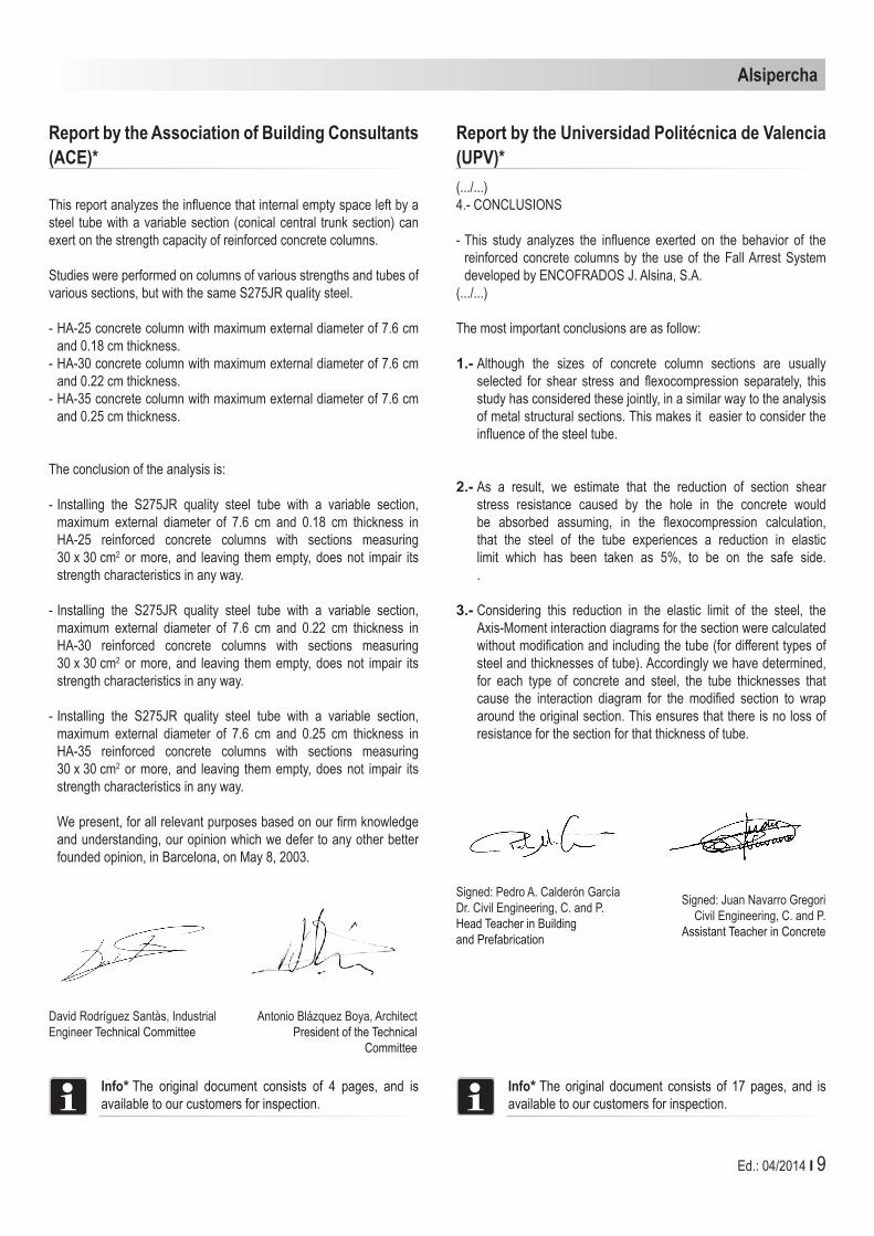
report by the Universidad Politécnica de valencia (UPv)*(.../...)4.- CONCLUSIONS
- This study analyzes the influence exerted on the behavior of the reinforced concrete columns by the use of the Fall Arrest System developed by ENCOFRADOS J. Alsina, S.A.
(.../...)
The most important conclusions are as follow:
1.- Although the sizes of concrete column sections are usually selected for shear stress and flexocompression separately, this study has considered these jointly, in a similar way to the analysis of metal structural sections. This makes it easier to consider the influence of the steel tube.
2.- As a result, we estimate that the reduction of section shear stress resistance caused by the hole in the concrete would be absorbed assuming, in the flexocompression calculation, that the steel of the tube experiences a reduction in elastic limit which has been taken as 5%, to be on the safe side. .
3.- Considering this reduction in the elastic limit of the steel, the Axis-Moment interaction diagrams for the section were calculated without modification and including the tube (for different types of steel and thicknesses of tube). Accordingly we have determined, for each type of concrete and steel, the tube thicknesses that cause the interaction diagram for the modified section to wrap around the original section. This ensures that there is no loss of resistance for the section for that thickness of tube.
report by the Association of Building Consultants (ACE)*
This report analyzes the influence that internal empty space left by a steel tube with a variable section (conical central trunk section) can exert on the strength capacity of reinforced concrete columns.
Studies were performed on columns of various strengths and tubes of various sections, but with the same S275JR quality steel.
- HA-25 concrete column with maximum external diameter of 7.6 cm and 0.18 cm thickness.
- HA-30 concrete column with maximum external diameter of 7.6 cm and 0.22 cm thickness.
- HA-35 concrete column with maximum external diameter of 7.6 cm and 0.25 cm thickness.
The conclusion of the analysis is:
- Installing the S275JR quality steel tube with a variable section, maximum external diameter of 7.6 cm and 0.18 cm thickness in HA-25 reinforced concrete columns with sections measuring 30 x 30 cm2 or more, and leaving them empty, does not impair its strength characteristics in any way.
- Installing the S275JR quality steel tube with a variable section, maximum external diameter of 7.6 cm and 0.22 cm thickness in HA-30 reinforced concrete columns with sections measuring 30 x 30 cm2 or more, and leaving them empty, does not impair its strength characteristics in any way.
- Installing the S275JR quality steel tube with a variable section, maximum external diameter of 7.6 cm and 0.25 cm thickness in HA-35 reinforced concrete columns with sections measuring 30 x 30 cm2 or more, and leaving them empty, does not impair its strength characteristics in any way.
We present, for all relevant purposes based on our firm knowledge and understanding, our opinion which we defer to any other better founded opinion, in Barcelona, on May 8, 2003.
Info* The original document consists of 4 pages, and is available to our customers for inspection.
David Rodríguez Santàs, Industrial Engineer Technical Committee
Antonio Blázquez Boya, Architect President of the Technical
Committee
Signed: Pedro A. Calderón GarcíaDr. Civil Engineering, C. and P.Head Teacher in Buildingand Prefabrication
Signed: Juan Navarro GregoriCivil Engineering, C. and P.
Assistant Teacher in Concrete
Info* The original document consists of 17 pages, and is available to our customers for inspection.

10 I Ed.: 04/2014
Alsipercha
Alsipercha Body review Procedure . - 84411
Control guidelines ProcedurePlace the Alsipercha system on two trestles
and open it up to:
- Check that the bolts, pins, and nuts of the various extensions are in good condition and that they can move freely.
- Check that the extensions are neither askew nor misshapen (maximum tolerance in both directions is 5 mm). Pay special attention to ensuring that the diagonal tube with spring is straight.
- Clean the concrete and particularly some areas between the two lugs, as this is the area where various hanger accessories are housed. If these are closed, open them with a hammer, until the beam can enter.
- Inspect the welds, especially on the ring to which the hood is attached.
If problems are identified with any of the above, contact the Alsina Service Department.
warning - never remove the Alsipercha Body’s diagonal tube. It contains a shock absorber. handling the tube may be dangerous. If any problem is observed in this diagonal, contact the Alsina Commercial Technician.
S.A. hook review Procedure - 83418
Control guidelines Procedure
- Check that the hook is neither askew nor misshapen.
If the deformation is minor, it can be fixed provided that the tube structure is not misshapen.
- Clean the concrete.- Check that there are no fractures.
Appendix 1: Conditions of use on site
Below are the guidelines for reviewing each component of the Alsina Alsipercha Fall Arrest System. Reviews should be performed regularly, once per year at the very least.
As explained in Alsina's Alsipercha Assembly and Safety Manual, this review does not replace the visual inspection that the user should perform each time he or she uses the Fall Arrest System.
retractable review Procedure - 84412
Control guidelines Procedure
Check that the belt winds automatically and unwinds normally along its whole length.
If it does not work, put the product to one side as it is faulty.
Check that the blocking function is operative, by pulling the belt sharply.
If it does not work, put the product to one side as it is faulty.
That the textile is in perfect condition, without tears or loose ends.
If it does not work, put the product to one side as it is faulty
That the metallic parts are not oxidised and that the karabiners work and block correctly.
That the system includes the red peg Otherwise, attach a new one.
It is important to check that the continuous energy absorber protected by the plastic and the fibres forming it, have not broken.
Otherwise the product will have to be put to one side because it has been dropped, and consequently it is faulty
Check that the hood assembly with eyebolts is in good condition. If any hoods are broken, misshapen, cracked, or missing a part, they must be removed. Pay close attention to how the hood's two upper eyebolts are attached. They should be welded or joined with a safety pin
Otherwise reject
Info To carry out the checks indicated below, it is not
necessary to remove the retractable from the protective red hood.

Ed.: 04/2014 I 11
Alsipercha
S.A. Cylindrical Leveller review Procedure - 83416
Control guidelines Procedure- Check that the leveller is in its original
condition. Verify that it enters and exits a housing tube that is in good condition.
- Check that there is no washer. Verify the level. Check that the leveller is not broken.
If problems are identified with any of the above, contact the Alsina Service
Department.
Textile Components review procedure: S.A. Sling - 84414, S.A. harness - 84415, Alargo harness with S.A. Jacket - 84421
Control guidelines Procedure- Check that all textile elements are present.
Check that there are no tears (especially along the edges) or loose threads.
- The textile material must be kept in a clean, dry place.
Otherwise reject

(1)
(2)
12 I Ed.: 04/2014
Alsipercha
Assembly process for the column gripper sleeve
Characteristics and advantages
- Patented product made in steel, proving to be a much more lightweight accessory, easy and quick to assemble, and which only needs a hammer for attachment.
- Designed and manufactured according to the DIN EN 795 anchor devices standard.
- It can be attached to steel columns (Sections with IPE, IPN, HEB type wings, etc.) with sections from 15 to 45 cm.
- Only two sellable codes which, once assembled, are inseparable (Integrated Safety)
- Can be assembled by competent works personnel
Component Description
HOOK S.A.Description: Component used to bring the Alsipercha fall arrest system closer to the worker when changing the anchorage.
code dimensions (cm) weight (kg)83418 140 x 2850 2
ALSIPERCHA BODyDescription: Inverted “L” shaped unit, anchored in the column with a working radius of 6.5 m that allows access to a surface area of 125 m2.
code dimensions (m) weight (kg)84411 2500 x 4300 80
S.A.V-METAL COLUMN GRIPPER SLEEVEDescription: Accessory Alsipercha element.
code dimensions (mm) weight (kg)83426 154 Ø65 1,24
S.A. V-METAL COLUMN GRIPPERDescription: Accessory Alsipercha element, for scaffolding (attaching) fall arrest system to metal columns with wings (IPE, IPN, HEB... section type, etc.)
code dimensions (mm) weight (kg)83424 755 x 55 6,27
HARNESS S.A.Description: Device anchoring the operator to the Alsipercha fall arrest system.
code dimensions (m) weight (kg)84415 1
RETRACTABLE DEVICE 10MDescription: Retractable component that locks on a sudden acceleration.
code dimensions (m) weight (kg)8441205 10 7
RETRACTABLE DEVICE W/PROTECTOR S.A.Description: Retractable component that locks on a sudden acceleration. It also has the Red Clamp, which is a clip placed in such a way that the strap of the retractable device stays hanging at a length of 1 m, so that it stays within reach of the workers.
code dimensions (m) weight (kg)84412 (1) 2,5 1,59984420 (2) 0,1
SLINGDescription: An essential component used to move the assembly with a crane, to take it to the column, or remove it once the work is complete.
code dimensions (m) weight (kg)84414 0.62

1
2
34
Ed.: 04/2014 I 13
Alsipercha
Assembly process
- For every Alsipercha sent to site, 2 S.A. V-METAL COLUMN GRIPPER units (code 83424) and 1 x S.A. V-METAL COLUMN GRIPPER SLEEVE unit (code 83426) will be sent.
- The S.A. V-METAL COLUMN GRIPPER SLEEVE will be assembled in one of the S.A. V-METAL COLUMN GRIPPERS, passing the nipple of the sleeve through the grooves of the GRIPPER plate (this solution is called the “labyrinth”, and once the SLEEVE is assembled in the GRIPPER it prevents them from separating from one another).
1 m
LEGEND1. Alsipercha2. S.A. Metal Column Gripper3. Metal column4. Rotation angle
- At the head of the metal column, we attach the S.A.V-METAL COLUMN GRIPPER, without SLEEVE, and 1 m below, we position the S.A.V-METAL COLUMN GRIPPER and the SLEEVE. Attach both GRIPPERS using a hammer, hitting the end nut hard (up to 50 Nm).
- Now the Alsipercha can be positioned, passing it through the housings in both grippers, until it abuts against the SLEEVE. Once the Alsipercha is connected, using the harness, the operator has a rotation angle of 280º approximately

14 I Ed.: 04/2014
Alsipercha
Alsipercha TripodAlsipercha Tripod assembly procedure
The ALSIPERCHA TRIPOD, together with Alsipercha, is a solution that allows operators to safely load/unload trucks from a trailer.
The ALSIPERCHA TRIPOD is folded up when it is delivered onsite. Once it has been placed in its work position, it is assembled according to the following steps:
2500 mm
2344 mm
2260 mm
1356 mm
2712 mm
3 x 2010kN
2000
mm
5500
mm
2500 mm
2344 mm
2260 mm
1356 mm
2712 mm
3 x 20
10kN
3000
mm
6500
mm
Component Description
ALSIPERCHA BODyDescription: Inverted “L” shaped unit.
code dimensions (m) weight (kg)84411 80
HOOK S.A.Description: Component used to bring the Alsipercha fall arrest system closer to the worker when changing the anchorage.
code dimensions (cm) weight (kg)83418 140 x 2850 2
SLINGDescription: An essential component used to move the assembly with a crane, to take it to the column, or remove it once the work is complete.
code dimensions (m) weight (kg)84414 0,62
RETRACTABLE DEVICE 10MDescription: Retractable component that locks on a sudden acceleration.
Código Dimensiones (m) Peso (kg)8441205 10 7
HARNESS S.A.Description: Device anchoring the operator to the Alsipercha fall arrest system.
code dimensions (m) weight (kg)84415 1
TRIPOD S.A.Description: Element that supports and stabilizes the Alsipercha.
code dimensions (m) weight (kg)84475 2 9084478 3 98
FH FISCHER ANCHORS Ø18 M12X138.Description:
code dimensions (m) weight (kg)83479 18 x 80 x 25 S 0,01

Ed.: 04/2014 I 15
Alsipercha
FH FISCHER ANCHORS Ø18 M12X138.Description:
code dimensions (m) weight (kg)83479 18 x 80 x 25 S 0,01
Step 1To open the tripod feet, release the connecting PINS.
Step 2Once the pin has been released, the first foot will open.
Step 3Secure it in the open position by placing the pin in the R position.
Alsipercha tripod mounting procedure
Info It is very important to mount the ALSIPERCHA TRIPOD on sufficiently compact and resistant terrain so that the anchor device provides sufficient safety guarantees. There are various terrain / slab / footing options:
option of anchoring to concrete/slab footing- Create a concrete footing that has the following characteristics as a
minimum: HA25 concrete or higher (minimum resistance of concrete for use = 10 MPa, if fresh concrete is used), measurements of 300 x 300 cm and thickness of 25 cm, as well as a scrap metal covering. In this case, the anchor will consist of placing 3 “M12 FISCHER FH 18X80/25 S HIGH RESISTANCE ANCHORS” (or equivalent).
3000 mm
250 mm
40 mm
3000 mm
option of anchoring to steel plate- Place the tripod on a steel plate that has the following characteristics
as a minimum: measurements of 300 x 300 cm and 4 cm thickness, with three M18 previously-bored threaded holes through which the anchors will pass (in this case it will be an 8.8 quality M18x50 DIN933 galvanised screw with an M18 DIN 125-A washer).

16 I Ed.: 04/2014
Alsipercha
Step 4ALSINA TRIPOD with one foot open.
Step 5Turn the TRIPOD 180 degrees, open the second foot, and place it upright. Use an anchoring element to secure the tripod to a high, fixed point so the structure does not overturn. Proceed to open the third foot.
Step 6ALSINA TRIPOD in the working position.
Step 7On the HA25 concrete sole plate, drill with an 18 mm - diameter bit to a depth of 140 mm.
Step 8The M12 FISCHER FH 18X80/25 S HIGH RESISTANCE ANCHOR is fitted.

70
100
8060
6050
Ed.: 04/2014 I 17
Alsipercha
Procedure for use on site
General Information
There are 5.5 or 6.5 metres from the anchor point to the floor, depending on the type of tripod chosen, meaning that the operator can work above the truck load in complete safety. The diameter of the circular surface occupied by the tripod base is 2.7 m
Safety information
The Alsipercha is only for the operations indicated in this document, to prevent them from falling when loading on or unloading from delivery vehicle platforms.
Other spare parts that are not supplied with the system must not be used.
Check all the parts of the Alsina unloading system components before installing. Never use the equipment if it is damaged or rusty, as this may affect its safety.
If anyone falls when using the Alsipercha system, the retractable system must be withdrawn from service and inspected by an appropriate person. If you have any queries, please contact Alsina.
Step 9With a dynamometric wrench, torque to 80 Nm. Repeat for all three anchors. Finally, using the crane, place the Alsipercha on top of the ALSIPERCHA TRIPOD.
2712 mm

100 mm
3000 mm 3000 mm
2400
mm
1
2
43
18 I Ed.: 04/2014
Alsipercha
Final assembly
Trucks that are 6 m long
To unload the 6-metre platform of a truck, only one Alsipercha system will need to be used. When parking the truck, the rear box/platform must be situated according to the distances shown in the following illustration:
LEGEND1. Alsipercha unloading system2. Alsipercha System3. 10 m retractable element4. Operator
Any operator unloading a truck with a 6 m platform, must use:
• suitable footwear• a reflective jacket and a helmet with chin protection• a safety harness• 0.3 m additional extension rope for subsequent anchoring
Once the operator has the PPE correct (Personal Protection Equipment), he can hang the additional 0.3 m rope on his harness by rolling it up and attach the other end of the fall arrest device to the retractable element with a snap hook.
The fall-stop device must include a retractable 10 m inertia reel.
The operator must be connected to the system before accessing the platform.
3000 mm 3000 mm
100 mm
2400
mm

100 mm
3100 mm
2400
mm
1
1
24
3100 mm6000 mm
4800 mm
2
3
3
Ed.: 04/2014 I 19
Alsipercha
Trucks that are 12 m long
As the image below shows, when a 12-metre truck is loaded and unloaded, two Alsipercha systems must be used simultaneously.
When parking the truck, the rear box/platform must be situated according to the distances shown in the illustration below.
The operator must be attached to two Alsipercha systems. This will help him control the movement on the 12 m long platform in the event of a fall.
If it should be necessary to access the outer corners of the platform, it is best to move the truck to ensure that the operator is within a range of 3.5 m from the structure.
LEGEND1. Alsipercha unloading system2. Alsipercha System3. 10 m retractable element4. Operator
Any operator unloading a truck with 12 m platform, must use:
• suitable footwear• a reflective jacket and a helmet with chin protection• a safety harness• 0.3 m additional extension rope for subsequent anchoring
Once the operator has the correct PPE (Personal Protection Equipment) he can hang the additional 0.3 m rope on his harness by rolling it up and attach the other end of the fall arrest device to the retractable element with a snap hook.
The fall arrest device is comprised of a retractable inertia reel of 10 m, to allow the operator to move freely to the ends of the truck.
The operator must be connected to the two systems before accessing the platform.
3100 mm 6000 mm 3100 mm
2400
mm
100 mm
4800 mm

20 I Ed.: 03/2014
Alsipercha
Alsipercha CoUTErwEIGhT SoLUTIonIntroduction
The MF Counterweight solution, together with the ALSIPERCHA fall prevention system, has been designed to allow the loading and unloading of equipment from the top of a flatbed delivery truck/trailer in a safe manner
Tested in compliance with the DIN EN: 795 standard, the MF Counterweight solution can be used on a site or in a loading yard and can be moved to alternative locations as the needs arise. The MF Counterweight solution incorporates an ALSIPERCHA unit, which can be separated and folded up for ease of transport between locations.
ALSIPERCHA BODyDescription: Inverted “L” shaped unit, anchored in the column with a working radius of 6.5 m that allows access to a surface area of 125 m2.
code dimensions (m) weight (kg)84411 80
HOOK S.A.Description: Component used to bring the Alsipercha fall arrest system closer to the worker when changing the anchorage.
code dimensions (cm) weight (kg)83418 9 x 4 2
SLINGDescription: An essential component used to move the assembly with a crane, to take it to the column, or remove it once the work is complete.
code dimensions (m) weight (kg)84414 0,62
RETRACTABLE DEVICE 10MDescription: Retractable component that locks on a sudden acceleration.
code dimensions (m) weight (kg)8441205 10 7
HARNESS S.A.Description: Device anchoring the operator to the Alsipercha fall arrest system.
code dimensions (m) weight (kg)84415 1
2UPN 1,22M MF GIRDERDescripcion:
code dimensions (m) weight (kg)
3490122 1,22 30,763490497 4,97 124,7
Component Description

Ed.: 03/2014 I 21
Alsipercha
M 20 DIN985 NUT
code dimensions (m) weight (kg)630000167 0,05
ALSIPERCHA MF AXIS
code dimensions (m) weight (kg)84044 35,4
PULLPROP 1,50-2,25 MF
code dimensions (m) weight (kg)34603 22,5
D/20X130 MF NUT
code dimensions (m) weight (kg)33701 0,32
PASADOR (R) SAFETy 4/74MM MF
code dimensions (m) weight (kg)33700 0,14
ALSIP. MF TRUCK WHEEL BASE
code dimensions (m) weight (kg)83034 90
ALSIPERCHA MF AXIS SUPPORT
code dimensions (m) weight (kg)83039 4
ALSIPERCHA MF STRENGTHENER
code dimensions (m) weight (kg)83038 2
DIN931 8.8 ZN SCREW
code dimensions (m) weight (kg)33729 20 x 100 0,483046 20 x 120 0,35

22 I Ed.: 03/2014
Alsipercha
Assembly instructionsStep 1On a flat surface, must be placed the 2UPN 4,97M MF GIRDER (Code 3490497). Then, the ALSIPERCHA MF AXIS (Code 83039) has to be installed over the girder, by using the 6th and 7th hole from the more spaced series of holes of the beam.
Step 2The shortest beams 2UPN 1,22M MF GIRDER (Code 3490122) needs to be placed perpendicular to the 2UPN 4,97M MF GIRDER (Code 3490497), by using the ALSIPERCHA MF STRENGTHENER (Code 83038). The beams joint must be done by using the M20X100 DIN931 8.8 ZN SCREW (Code 33729) with the M 20 DIN985 NUT (Code 630000167), as follows:
Step 3The ALSIPERCHA MF AXIS (Code 84044) must be connected to the ALSIPERCHA MF AXIS SUPPORT (Code 83039), by using the M 20X120 DIN931 8.8 ZN SCREW (Code 83046), and the M 20 DIN985 NUT (Code 630000167), as follows:

Ed.: 03/2014 I 23
Alsipercha
Step 6Finally, the ALSIPERCHA FALL PREVENTION SySTEM (Code 84411) has to be installed inside the ALSIPERCHA MF AXIS (Code 84044), to adopt its final configuration.
Step 5The ALSIP. MF TRUCK WHEEL BASE (Code 83034) has to be put over the 2UPN 4,97M MF GIRDER (Code 3490497) at a distance between 0,85m and 1,00m from the ALSIPERCHA MF AXIS (Code 84044). The distance between the TRUCK WHEEL BASES (Code 83034), will depend on the distance between the axis trucks.
Step 4The PULLPROP 1,50-2,25 MF (Code 34603), has to be joined to the ALSIPERCHA MF AXIS (Code 84044), and to the two kind of GIRDERS (Codes 3490122 and 3490497), by using the D/20X130 MF NUT (Code 33701) and the PASADOR (R) SAFETy 4/74MM MF (Code 33700), as follows:
Info The union between the PULLPROP 1,50-2,25 MF (Code 34603), and the GIRDERS (Codes 3490122 and 3490497) can be done by using any of its exterior holes.
24 I Ed.: 4/2014
Maintenance and safety
Maintenance, use and safety
Alsina performance criteria with regard to Technical requirements, Safety and Accident Prevention at the worksite
Background After more than 60 years in the Spanish market, the Alsina Group has become one of the largest companies in the formwork sector, with a construction market share of more than 20%. From its foundation, company priorities have been safety at the worksite, quality in the widest sense and productivity. The primary aim of the company is to industrialize concrete structure formwork.
Alsina dedicates a large part of its technical resources to working towards continuous improvement of products and processes, in order to add new solutions at both the functional and safety levels and make available a state-of-the-art and innovative range of products. More than 50 patents in Spain, in addition to several recent international patents, bear witness to the company’s commitment in this area.
r+D+I
Both the Technical Department and the R+D Department use advanced computer equipment to simulate real situations when performing product related calculations. This allows us to develop a large number of new high quality and innovative products; the company also works closely with Universities, Laboratories and Engineering Companies.
In general we govern ourselves in relation to safety and technical requirements based on European regulations. Our products are certified on the basis of Spanish and European Community standards by recognised institutions. The most significant of these, among others, are: Intemac, Indus, Itec, ACE, LGAI, Bureau Veritas, etc.
Training and Standards
Above all, the purpose of this Assembly and Safety Manual is to assist whoever works with our products. This is why we make it available to our customer before the start of formwork assembly work. If you do not have a copy or require more copies, do not hesitate to contact Alsina directly or the Technical Salesperson responsible for your project.
This Manual has been prepared with the intention of supporting the theoretical-practical training given at the beginning of the construction work. Figures and diagrams are included to promote maximum understanding on the part of the workers who will be involved in the use and maintenance of the equipment.
../..Alsina supplies the formwork material and is responsible for the delivery of the equipment in good working condition, in compliance with the criteria set out in our quality manual. Given that Alsina does not perform the assembly or manage the construction work, the user bears responsibility for the use and maintenance of the equipment.
In addition to the recommendations contained in this manual, the safety and health standards in force for the construction sector in force in each geographical area.

Maintenance, use and safety
Ed.: 04/2014 I 25
Conditions of use
The system has been designed and created for the specific uses and applications described in this manual. Therefore, we take no responsibility for the use of the equipment in situations other than those considered in this manual.
At the time of assembly, the material must always be checked by a competent person, who must ensure that it is fit for use. To this end, each system has specific control guidelines defined for its main components. These guidelines can be found in the Annex (Annex 1) at the end of this section. In accordance with these criteria, when a part that is not fit for use is identified, it must be rejected.
Set out below are the main considerations to be taken into account during the installation, recovery and system maintenance phases.
Installing the components of the system
1. All the components are sufficiently strong and stable to support the loads and stresses described in this manual. It is essential to install all the components included in the system, with all the accessories assembled and correctly attached and especially to verify that the panels are correctly positioned and supported.
2. Alsina disclaims all responsibility if the system components are substituted with other, similar components supplied by another company.
3. In extreme weather conditions (very dry and hot) it is necessary to wet the panels. The Alsina system allows the panels to be nailed to the dropheads incorporating wood which is almost essential in the perimeters, in areas near interior openings, column filling, in the event of strong winds, in angled formwork and generally wherever there is a risk of the panel moving for any other reason.
4. To guarantee proper support, the panel placed between two aligned dropheads should rest on both simultaneously, so boards cut to size can be placed in between. Actually, due to the size combination of the panel and the dropheads, when one panel rests on both dropheads, the sequence of panels which follows will also be supported correctly.
Otherwise nail the panels or use an intervening drophead.
5. Ensure that the connections are effected properly. The nails, when necessary, should not be nailed to the same row of wood, but staggered, making sure than they are neither loose nor protrude from the wood. Special care should be taken with column joints.
6. Do not leave any panels or pieces of wood loose, nor loose or unstable components. Storage components and working tools must be placed or stored in such a way as to avoid risk of collapse, falling or turning over.
7. The beams must have all their props present even if their pivots coincide with the support girders; the latter must be level and as for the dropheads, verify that they are all correctly placed and the pins are closed.
8. The worksite technician must decide whether it is appropriate to brace all or only part of the post-shores, depending on the structural component being formworked, and legislation and practice in the community or country.
9. During the entire assembly process, the beams must always be supported by a minimum of one line of support girders, except at the starting point where there will be two.
10. In the subsequent placement of the various components, try to provide maximum stability (using tripods, X-crosses, ...) It is important to brace the first line of support girders to the columns.
11. During the positioning of panels, handrails, perimeter nets,... and whenever there is risk of falling from a height, in order to prevent accidents and ensure safety, we recommend the use of the fall prevention system designed by Alsina, the deployment of safety nets under the floor slabs attached to the post-shores with hook fasteners (in such case, follow the manufacturer’s and/or installer’s instructions for the assembly of the nets) (see Annex 3), a lifeline between columns, etc.
The risk of fall from a height must be assessed by a competent person who should take into consideration the experience of the formworkers, the project conditions, current legislation, etc. He should to consider the option of assembly from below or equivalent protection if regarded as necessary.

Maintenance, use and safety
26 I Ed.: 04/2014
12. All openings located on the inside of the formworking surface must be properly protected by handrails or nets, mesh or other equivalent protection, taken collectively, to prevent accidents.
The entire perimeter of first the horizontal formwork and then the floor structure, must have handrails installed, in addition to the collective perimeter protection system consisting of gallows-type nets, or cantilever type (also known as tray or canopy), or other collectively equivalent protection. The handrails must be at 90 cm from floor level, and have mid-height protection and baseboards, the latter to prevent objects from falling.
workers must use the individual protection measures required for each phase: helmet, gloves and boots.
13. When workers have to move on partial floor formwork, place toeboards over the flooring blocks to prevent them from breaking.
14. For floor structure heights over 4.9 m, we do not recommend counter scaffolding with post-shores, as this has resulted in a large number of accidents and requires extremely precise assembly by specialized personnel under the supervision of expert, competent technicians. Alsina disclaims all responsibility should a solution of this type be attempted.
15. In cases where a post-shore might be perforated, we recommend that these rest on boards, rather than resting directly on the previous floor structure. If the post-shores for the floor structure of the bottom floor are supported on the ground, they should never do so directly, but rather on panels that distribute the load. It is important that the post-shores at the edges of the floor structure are properly supported.
16. To prevent the post-shores from falling on persons and/or materials during hoisting, loading or unloading operations, we recommend using trays or transportation containers and always following the manufacturer’s instructions. An alternative is to hoist the post-shores using slings, distribution beams, balance beams, etc in packs strapped at both ends to stabilize the set and prevent it from moving horizontally.
recovering the components of the system
1. Recovery requires careful study and cordoning off of areas, to avoid unexpected fall of materials. Underneath each of these areas only those workers required for the operation must be present.
2. The components to be recovered must be loosened gradually so that, if deformations are discovered, they can be braced immediately.
3. During the 1st stage of formwork stripping, do not remove any post-shores from the beams that are still providing support.
4. In general, no post-shores are to be removed before 3 days have passed from the time concrete is poured, and always after the concrete has had time to set and acquire a minimum strength of 40%.
5. It is not advisable to deposit heavy loads on areas where concrete has been recently poured and formwork recently stripped such as; deposit of materials, machinery or lifting equipment, allowing movement of personnel on such surfaces if this runs the risk of becoming too great and cause dynamic stresses that may result in accidents.
6. The complete stripping of formwork relating to the 2nd phase must be carried out 28 days after pouring the concrete or when the concrete is safe enough, free of excessive deformation and has achieved the necessary strength to bear the stresses to which it will be subjected.
7. After each position and before the next assembly, clean the grout from all the beams and panels and remove all the nails from the panels. Never do this while the beams are mounted, to avoid dangerous situations.
../..
Info While performing formwork stripping of the "with supports" system (rebracing) the special conditions included in Annex 2 must also be taken into account.
Maintenance, use and safety
Ed.: 04/2014 I 27
Maintenance conditions
A pre-established expiry date can not be set for formwork, but improper use of equipment that could damage it must be avoided. When the material fails to satisfy the requirements established in Annex 1, it must be replaced, since its state of preservation will then be below the minimum requirement.
The users are responsible for maintenance of all items of equipment, whether rented or the customer's property, for reuse or alternatively to reject them.
It is advisable to remove all nails and apply a concrete release agent immediately after formwork stripping and before the next position to prolong the working life of panels.
Metal components must be cleaned of concrete remains with a scraper, never striking them with a hammer. Also avoid use of nails in such way as might damage the material. In the interests of this, wooden strips have been inserted in the dropheads.
Encofrados J. Alsina, S.A. (Spain)Servicio de encofrados Alisan, S.A. (Spain)Moldajes Alsina, Ltda. (Chile)Alsina Forms Co., Inc. (USA)Soluções de Cofragem Alisply, Lda (Portugal)Casseforme Alsina s.p.a. (Italy)Encofrados Alsina del Uruguay, S.A. (Uruguay)Cofralsi, S.A.R.L. (Morocco)Alsina Polska Sp. z o.o. (Poland)Cofraje Alsina Romania, SRL (Romania)Encofrados Alsina del Perú S.A.C. (Peru)Encofrados Alsina de Panamá, S.A. (Panama)<<GROUP ALSINA>>