alphonso energy | credence robotics
TRANSCRIPT

Alphonso Energy | Credence Robotics
1 © Material of CREDENCEROBOTICS LLP | Centralized Smart Energy Saver Systems
Alphonso Energy | Credence Robotics
2 © Material of CREDENCEROBOTICS LLP | Centralized Smart Energy Saver Systems
TABLE OF CONTENTS
Abstract ................................................................................................................................................................. 3
Introduction .......................................................................................................................................................... 3
The Fundamentals ............................................................................................................................................... 4
The Problem Statement ...................................................................................................................................... 4
Existing Solutions ................................................................................................................................................. 8
Problems with existing solutions: ........................................................................................................................... 9
Our Solution ....................................................................................................................................................... 10
Harmonic Suppression: ........................................................................................................................................... 10
Voltage Optimization: ............................................................................................................................................... 12
PF correction: ............................................................................................................................................................. 12
Benefits ............................................................................................................................................................... 13
Enhanced Device Life Safety: ................................................................................................................................. 13
Increased System Capacity: .................................................................................................................................... 13
Greater Reliability:..................................................................................................................................................... 13
Reduced Energy and Operating Costs: ................................................................................................................ 13
Energy Analytics: ....................................................................................................................................................... 14
Case Studies ....................................................................................................................................................... 14
L’Azurde, Saudi Arabia: ............................................................................................................................................ 14
Intel, JLL L3, Bangalore: ............................................................................................................................................ 14
Sony Electronics, Malaysia: ..................................................................................................................................... 15
Conclusion .......................................................................................................................................................... 15

Alphonso Energy | Credence Robotics
3 © Material of CREDENCEROBOTICS LLP | Centralized Smart Energy Saver Systems
ABSTRACT
This paper is intended to give an overview of Centralized Smart Energy Savers and is
aimed at those who have some electronics/electrical background but little or no
knowledge of harmonics. The basics of harmonics are explained briefly emphasizing
thee SMPS loads. Common types of harmonic sources present in industry are
addressed. The potential ill-effects due to harmonics are detailed. The methods of
reducing harmonics and energy consumption are discussed along with case studies.
INTRODUCTION
Power system harmonics is an area that is receiving a great deal of attention recently.
This is primarily due to the fact that non-linear (or harmonic producing) loads are
comprising an ever-increasing portion of the total load for a typical industrial plant.
The increase in proportion of non-linear load has prompted more stringent
recommendations in IEEE Std. 519 and stricter limits imposed by utilities. Incidence
of harmonic related problems is low, but awareness of harmonic issues can help to
increase plant power system reliability.
A typical Manufacturing Plant or any Commercial Building will have thousands of
switched-mode power supplies (SMPS) on-line, 24 hours a day, 7 days a week, 365
days a year. There’s the SMPS for the computers, the power supply for Lighting
systems, HVAC, Variable Frequency Drives, Inverters, DC Converters, etc. All of them
produces Harmonic Currents.
Alphonso Energy | Credence Robotics
4 © Material of CREDENCEROBOTICS LLP | Centralized Smart Energy Saver Systems
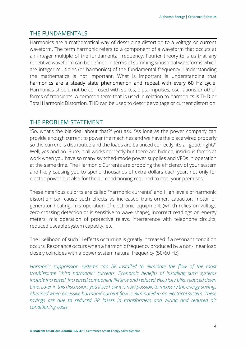
THE FUNDAMENTALS
Harmonics are a mathematical way of describing distortion to a voltage or current
waveform. The term harmonic refers to a component of a waveform that occurs at
an integer multiple of the fundamental frequency. Fourier theory tells us that any
repetitive waveform can be defined in terms of summing sinusoidal waveforms which
are integer multiples (or harmonics) of the fundamental frequency. Understanding
the mathematics is not important. What is important is understanding that
harmonics are a steady state phenomenon and repeat with every 60 Hz cycle.
Harmonics should not be confused with spikes, dips, impulses, oscillations or other
forms of transients. A common term that is used in relation to harmonics is THD or
Total Harmonic Distortion. THD can be used to describe voltage or current distortion.
THE PROBLEM STATEMENT
“So, what’s the big deal about that?” you ask. “As long as the power company can
provide enough current to power the machines and we have the place wired properly
so the current is distributed and the loads are balanced correctly, it’s all good, right?”
Well, yes and no. Sure, it all works correctly but there are hidden, insidious forces at
work when you have so many switched-mode power supplies and VFDs in operation
at the same time. The Harmonic Currents are dropping the efficiency of your system
and likely causing you to spend thousands of extra dollars each year, not only for
electric power but also for the air-conditioning required to cool your premises.
These nefarious culprits are called “harmonic currents” and High levels of harmonic
distortion can cause such effects as increased transformer, capacitor, motor or
generator heating, mis operation of electronic equipment (which relies on voltage
zero crossing detection or is sensitive to wave shape), incorrect readings on energy
meters, mis operation of protective relays, interference with telephone circuits,
reduced useable system capacity, etc.
The likelihood of such ill effects occurring is greatly increased if a resonant condition
occurs. Resonance occurs when a harmonic frequency produced by a non-linear load
closely coincides with a power system natural frequency (50/60 Hz).
Harmonic suppression systems can be installed to eliminate the flow of the most
troublesome "third harmonic" currents. Economic benefits of installing such systems
include increased, Increased component lifetime and reduced electricity bills, reduced down
time. Later in this discussion, you’ll see how it is now possible to measure the energy savings
obtained when excessive harmonic current flow is eliminated in an electrical system. These
savings are due to reduced I²R losses in transformers and wiring and reduced air
conditioning costs.

Alphonso Energy | Credence Robotics
5 © Material of CREDENCEROBOTICS LLP | Centralized Smart Energy Saver Systems
Harmonic Current: Harmonic currents are a direct result of the way in which a switched-mode power
supply (SMPS) draws current from the system. The input circuit of an SMPS is a bridge
rectifier that changes the 110/240-volt AC input to DC. A capacitor smoothens this
DC to eliminate voltage ripples and the resultant DC bus has a voltage of about 170
volts when the AC rms input is 120 volts. Although the AC voltage is a sine wave, the
rectifier draws its current in spikes as shown in Figure 1. These spikes require that the
AC supply system provide harmonic currents, primarily 3rd, 5th and 7th. These
harmonic currents do not provide power to the SMPS, but they do take up
distribution system capacity.
Figure 1. Here's our first problem: Although the AC voltage is a Sine wave, the Rectifier circuits in power supply systems
and other circuitries draw its current in Spikes
The principal harmonic current is the 3rd (150/180 Hz) and the amplitude of this
current can be equal to or even greater than that of the fundamental current.

Alphonso Energy | Credence Robotics
6 © Material of CREDENCEROBOTICS LLP | Centralized Smart Energy Saver Systems
Harmonic Current Flow in 3 Phase Systems: When SMPS loads are connected as shown in Figure 2, each phase wire carries both
the 60Hz fundamental current that supplies power to the SMPS and the harmonic
currents that are there because of the way the SMPS draws its current. While most
of the harmonic currents cancel in the neutral wire, just as the 60Hz currents do, the
3rd harmonic current and other currents divisible by three are additive in the neutral
wire.
Thus, if the 3rd harmonic current were 100 amps in each phase, the 3rd harmonic
current returned to the X0 transformer connection by the common neutral wire
would be 300 amps.
Figure 2 3 Phase system with Phase-Neutral Computer Loads.
This fact has implications for system design, since the entire electrical system must
meet the national electrical code specifications for wire and conduit size. If it is
expected that SMPS loads will cause high neutral currents, wires must be sized for
the anticipated load. Instead of downsizing neutral wires, once common practice for
a system supporting only linear loads, now neutral wires must be oversized or
doubled. Larger conduit must be installed to handle more or larger wires. (Although
the code permits downsized neutrals if the system is not powering non-linear loads,
language in NEC 310.15(B)(4)(b, c)(2002) requires neutral conductors to be
considered current-carrying conductors when nonlinear (SMPS) loads are present. It
should be noted that there is no code requirement for double neutrals, only that the
neutrals be properly sized for the expected current.)

Alphonso Energy | Credence Robotics
7 © Material of CREDENCEROBOTICS LLP | Centralized Smart Energy Saver Systems
Problems Caused By 3rd Harmonic Currents: The effect of current distortion on distribution systems can be serious, primarily due
to the increased current flowing throughout the system. Following are some of the
problems that must be considered:
1. All distribution systems are rms current limited. For instance, a 150 kVA
208/120 wye transformer is rated for 416 rms amps per phase. The more
harmonic current flowing, the less fundamental current can be supplied. Since
the harmonic current does not deliver any power, its presence uses up system
capacity and reduces the number of loads that can be powered. Either the
system must be de-rated or a larger system, that can only be partially utilized,
must be installed.
2. Harmonic currents flowing through the system wiring cause increased I²R heat
losses. This heating can increase the temperature of wires and switchgear to
the point that erratic operation or even fires can occur.
3. Balanced 3rd harmonic currents cannot flow out of a delta primary. Therefore,
they circulate in the primary of the transformer where they are dissipated as
heat, Figure. 2. The current circulating in the transformer delta primary winding
contributes to the load on the winding, but does not flow through the primary
circuit breaker protection. Thus, the transformer primary winding can be
overloaded and the breaker that is expected to protect the transformer will
not do so.
4. Heat dissipated by transformers, switchgear, and wiring represents wasted
energy. Energy losses, brought about by harmonic current flow, can result in
significant increases in operating costs.

Alphonso Energy | Credence Robotics
8 © Material of CREDENCEROBOTICS LLP | Centralized Smart Energy Saver Systems
EXISTING SOLUTIONS
Traditional methods used to mitigate the effects of harmonic currents involve
“accommodation” of the currents after they are in the system.
1. Overbuild the system to handle the extra current. Double-sized neutral wires,
oversized switchgear, and transformers de-rated to less than their full capacity
are examples of system overbuilding.
2. Install a k-Rated Transformer. To reduce the chance of transformer failure due
to overheating, special transformers, known as “k-rated,” have been designed
to handle high harmonic loading, including 3rd harmonic currents circulating
in the delta primary. The k-rated transformer will survive overheating when
subjected to high harmonic loading, but the harmonic currents are still present in
the system.
3. Install a zig-zag reactor, the zig-zag reactor contains special windings
connected so as to present a low impedance to 3rd harmonic currents and a
high impedance to 60 Hz currents. When a zig-zag reactor is connected
between the phases and neutral of a 3-phase system, the 3rd harmonic
currents are diverted through the device. These currents no longer flow, from
the point where the zigzag is connected in the system, upstream to the
transformer. However, the phase and neutral wires from the zig-zag toward the
loads still carry all the harmonic currents including the 3rd, and double neutral
wires are recommended.
4. Install a zig-zag transformer. A “zig-zag” transformer can be used to replace
the standard transformer in a system. This device has the special windings of
the zigzag reactor built into the transformer secondary so that the 3rd
harmonic currents are cancelled in the secondary and do not circulate in the
primary winding. Again, the phase and neutral wires from the transformer to the
loads still carry all the harmonic currents and double neutral wires are
recommended

Alphonso Energy | Credence Robotics
9 © Material of CREDENCEROBOTICS LLP | Centralized Smart Energy Saver Systems
Problems with existing solutions:
While accommodation methods enable the electrical system to survive harmonic
currents, they have a number of shortcomings.
1. Useful system capacity is not changed. Harmonic currents still flow throughout
the system wiring and rms current is not decreased.
2. Heating of wires and switchgear is not reduced. Although the temperature of
transformers may be reduced, harmonic currents still flow throughout the
system wiring.
3. Energy losses due to I²R heating are not reduced. Since the harmonic currents
still flow throughout the system wiring, energy is still wasted. In fact, studies
have shown that the installation of certain accommodation methods may
actually increase energy losses. The typical impedance of zig-zag transformers
and k-rated transformers is lower than that of a standard transformer.
Likewise, an oversized transformer typically shows a lower impedance than a
smaller transformer. Since transformer impedance is lower, harmonic current
flow throughout the system is actually increased.

Alphonso Energy | Credence Robotics
10 © Material of CREDENCEROBOTICS LLP | Centralized Smart Energy Saver Systems
OUR SOLUTION
The Centralized Smart Energy Savers works on the principle of Harmonic
Suppression (Referred to as HSS), uses Voltage optimization techniques and PF
Correction units to not just get rid of harmonic problems. But also, to reduce energy
consumption, to increase power quality and to reduce electricity bills. On a whole,
saving energy and enhancing the equipment life.
Harmonic Suppression:
Harmonic suppression in Centralized Smart Energy Saver Systems use a unique
approach to mitigate harmonic currents in the distribution system. Their applications
are built on principle of “Prevention is better than Cure”
The Centralized Smart Energy Saver Systems are designed to prevent the flow of
harmonic currents in the distribution system, rather than treating or accommodating
the currents after they are there. The Centralized Smart Energy Saver Systems
consists of a parallel resistive/inductive/capacitive (RLC) network tuned to the 3rd
harmonic, or 180 Hz for a 60 Hz fundamental frequency.

Alphonso Energy | Credence Robotics
11 © Material of CREDENCEROBOTICS LLP | Centralized Smart Energy Saver Systems
The electrical characteristics of this type of circuit are such that it has a very high
resistance to the flow of 3rd harmonic current and a very low resistance to the flow
of the fundamental 60Hz current. Application of the HSS is shown in Figure 3.
Figure 3 Phase system with Phase - Neutral loads and HSS
The Centralized Smart Energy Saver Systems is connected between the neutral wire
and the 3 Hot Wires. All current that flows through the phase wires to the load must
return through the neutral. If 3rd harmonic current cannot flow in the neutral, due to
the high impedance of the Centralized Smart Energy Saver Systems, then no 3rd
harmonic current can flow in the phase wires.
The damaging 3rd harmonic current is blocked throughout the entire distribution
system from the transformer out to the furthest load. There is no 3rd harmonic
current circulating in the delta transformer primary because there is no 3rd harmonic
current available to circulate. The transformer is now fully protected by the primary
circuit breaker against overloading.
Phase wires have more capacity available to carry useful load and double neutrals
are not necessary. The neutral, for code purposes, need no longer be considered a
current carrying
conductor. Overheating of transformers, switchgear, and wiring is eliminated,
increasing the lifetime of all system components.

Alphonso Energy | Credence Robotics
12 © Material of CREDENCEROBOTICS LLP | Centralized Smart Energy Saver Systems
Voltage Optimization:
The Centralized Smart Energy Saver Systems uses special transformers to perform
Voltage Optimization, which is a proven energy-saving technique of reducing and
cleaning the electricity voltage supplied to a site, in order to:
• Reduce power losses by eliminating excessive consumption.
• Improve power quality in order to reduce wear and extend the life of electronic
equipment.
When additional measures are taken such as balancing phase voltages, and filtering
harmonics and transients from the supply, the process is known as Voltage Power
Optimization, or VPO.
When coupled with other smart grid power management technology and Analytics
Software, Voltage Power Optimization gives the end-user the ability to manage and
optimize their supply in order to immediately correct power quality problems from
the grid, and does so with great efficiency.
In the UK and Europe, the use of Voltage Power Optimization over the last five years has
achieved average energy savings of around 13%. This effectiveness has contributed to
making voltage optimization one of the fastest-growing energy saving techniques on the
world market.
Many major businesses (such as Tata Consultancy Services, Kirloskar, Tata Motors,
GE Healthcare, Motorola, Infosys, Ikea, etc.), and Public Sector organizations (such as
Amman Municipality In Jordan, BESCOM in Bangalore, Etc.) use Centralized Smart
Energy Saver Systems as a direct energy conservation measure.
PF correction:
The Centralized Smart Energy Saver Systems are integrated with power factor
correction circuits. It is a technique of increasing the power factor of a power supply.
Switching power supplies without power factor correction draw current in short
(Figure 1), high-magnitude pulses. These pulses can be smoothed out by using active
or passive techniques. This reduces the input RMS current and apparent input power,
thereby increasing the Power Quality.
Power factor correction tries to push the power factor of the electrical system such
as the power supply towards 1, and even though it doesn’t reach this it gets to as
close as 0.99 which is acceptable for most applications. With power factor equal to 1
or as close as possible, there are lower losses and all power generated is utilized
efficiently.

Alphonso Energy | Credence Robotics
13 © Material of CREDENCEROBOTICS LLP | Centralized Smart Energy Saver Systems
• The technical benefits: Improved efficiency and reduction in power demand,
hence a reduction in the load on the switching gear and cables, reduced costs
to the consumer and support for more load.
• Commercial benefits: There are reduced system losses and less capital cost
for the generating company. In addition, there are saving on electricity costs,
since there are no charges for the excess reactive power.
• Environmental benefits: Reduced Co₂ Emissions.
BENEFITS
Enhanced Device Life Safety:
3rd harmonic currents flowing in the system can overload transformers, switchgear,
and wiring. With neutral currents greater than the phase currents, facilities, and
particularly older facilities, are at risk from overheated wiring leading to fires.
Transformers with high 3rd harmonic currents circulating in the primary, and
unprotected against overloading, can fail or catch fire.
By eliminating 3rd harmonic currents from the transformer to the furthest outlet, the
Centralized Smart Energy Saver Systems eliminates the risk of overcurrent caused
fires.
Increased System Capacity:
All electrical distribution systems are rms current limited. Harmonic currents carried
by transformers, switchgear, and wiring use up system capacity that could be used
to carry 60Hz currents that do work. By eliminating 3rd harmonic currents throughout
the entire distribution system, the Centralized Smart Energy Saver Systems provides
the facility with more useful capacity without requiring that the electrical system be
upsized.
Greater Reliability:
The major cause of failure for transformers and switchgear is overheating. Random
breaker tripping due to harmonic heating is well known. The elimination of 3rd
harmonic currents reduces heat in all parts of the distribution system, thereby
reducing the likelihood that system components will fail or trip off due to excessive
temperatures.
The elimination of high neutral currents lowers neutral - ground voltages and reduces
the possible data errors.
Reduced Energy and Operating Costs:
Excessive heat in electrical distribution systems means wasted energy. The heat is
due to I²R losses in all system components, and appears directly in energy bills as
increased kW hour charges. Installation of the Centralized Smart Energy Saving
Systems reduces I²R Losses and the voltage optimization allows the system to deliver
Alphonso Energy | Credence Robotics
14 © Material of CREDENCEROBOTICS LLP | Centralized Smart Energy Saver Systems
optimum voltage required for the loads, reducing the kWh. Saving energy between
7% to 30% based upon the load and leads to a direct reduction in energy costs.
Energy Analytics:
Energy analytics is the process of gathering electrical data with the help of software
in order to assist energy suppliers and users to analyze, supervise, and optimize
energy related KPIs like production costs, consumption, production distribution, and
many others. By using an energy saver dashboard, one can thus improve profit
margins as well as manipulate and understand large-scale trends in the industry.
CASE STUDIES
Three case studies are outlined below. In each study, neutral 3rd harmonic currents
were almost totally eliminated and useful load capacity was increased. It was
estimated that energy savings due to the Centralized Smart Energy Saver Systems
would result in complete payback of the purchase cost in 11 to 26 months.
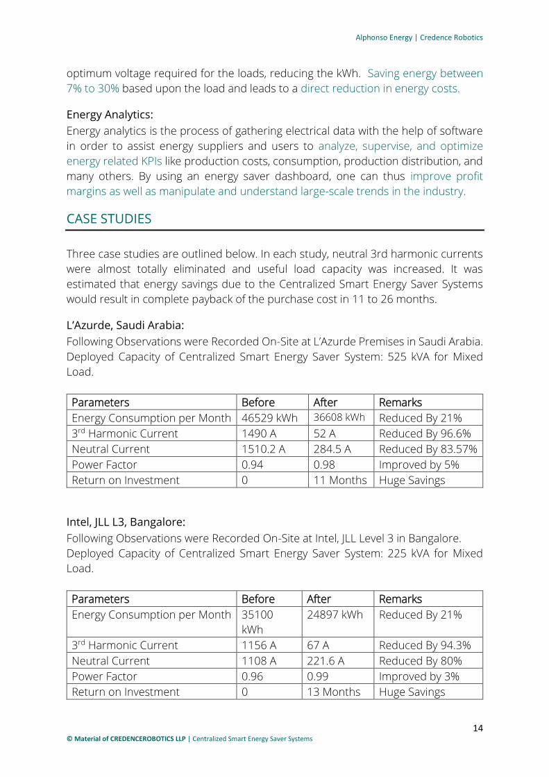
L’Azurde, Saudi Arabia:
Following Observations were Recorded On-Site at L’Azurde Premises in Saudi Arabia.
Deployed Capacity of Centralized Smart Energy Saver System: 525 kVA for Mixed
Load.
Parameters Before After Remarks
Energy Consumption per Month 46529 kWh 36608 kWh Reduced By 21%
3rd Harmonic Current 1490 A 52 A Reduced By 96.6%
Neutral Current 1510.2 A 284.5 A Reduced By 83.57%
Power Factor 0.94 0.98 Improved by 5%
Return on Investment 0 11 Months Huge Savings
Intel, JLL L3, Bangalore:
Following Observations were Recorded On-Site at Intel, JLL Level 3 in Bangalore.
Deployed Capacity of Centralized Smart Energy Saver System: 225 kVA for Mixed
Load.
Parameters Before After Remarks
Energy Consumption per Month 35100
kWh
24897 kWh Reduced By 21%
3rd Harmonic Current 1156 A 67 A Reduced By 94.3%
Neutral Current 1108 A 221.6 A Reduced By 80%
Power Factor 0.96 0.99 Improved by 3%
Return on Investment 0 13 Months Huge Savings

Alphonso Energy | Credence Robotics
15 © Material of CREDENCEROBOTICS LLP | Centralized Smart Energy Saver Systems
Sony Electronics, Malaysia:
Following Observations were Recorded On-Site at Sony Electronics, in Malaysia.
Deployed Capacity of Centralized Smart Energy Saver System: 225 kVA for Mixed
Load.
Parameters Before After Remarks
Energy Consumption per Month 1145 kWh 868 kWh Reduced By 24.1%
Power Factor 0.94 0.99 Improved by 5%
Return on Investment 0 16 Months Huge Savings
CONCLUSION
The Centralized Smart Energy Saver System is a well-established technology. As the
case studies show, it has been embraced by a wide variety of users, including major
Automobile Manufacturers, Showrooms, Shopping Complex, Electronics
Manufacturers, Pharmacy Industries, Hospitals, Hotels, Resorts, IT Industries and
Other Engineering Manufacturers.
In short, any group that uses non-linear Loads can benefit from this technology. The
capacity and energy savings are well documented and life safety and reliability issues
also are addressed. The bottom line is that the installation of a Centralized Smart
Energy Saver Systems can pay for itself, by energy savings, in one to three years.
For Further Information, Contact:
Credence Robotics, #34/4A, 2nd Floor, Vinayaka Arcade, Dr Vishnuvardhana Road,
Near RNSIT, RR Nagar, Bengaluru, Karnataka State 560098, India.
Email Us at: [email protected]
Call Us at: +91 6360705635 | +91 9148854243