alpha particle radioactivity measurements
TRANSCRIPT
Ionizing Radiation Division 43030C, 43040C, 43050C IRD-P-02
RADIATION DETECTORS CALIBRATION
Version Date Author Approval Pages Filename
4.00 2/8/2010 LEK/MU LRK 1 of 18 Procedure02v400
Alpha Particle Radioactivity Measurements
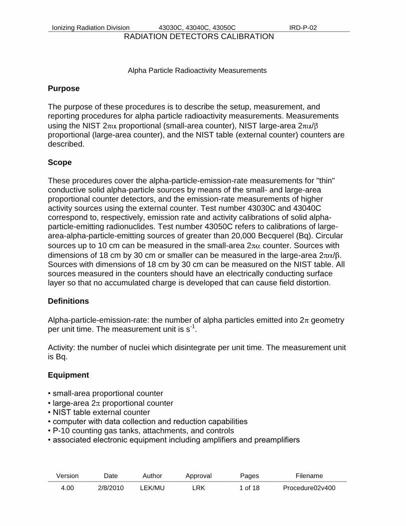
Purpose The purpose of these procedures is to describe the setup, measurement, and reporting procedures for alpha particle radioactivity measurements. Measurements
using the NIST 2 proportional (small-area counter), NIST large-area 2 / proportional (large-area counter), and the NIST table (external counter) counters are described. Scope These procedures cover the alpha-particle-emission-rate measurements for "thin" conductive solid alpha-particle sources by means of the small- and large-area proportional counter detectors, and the emission-rate measurements of higher activity sources using the external counter. Test number 43030C and 43040C correspond to, respectively, emission rate and activity calibrations of solid alpha-particle-emitting radionuclides. Test number 43050C refers to calibrations of large-area-alpha-particle-emitting sources of greater than 20,000 Becquerel (Bq). Circular
sources up to 10 cm can be measured in the small-area 2 counter. Sources with
dimensions of 18 cm by 30 cm or smaller can be measured in the large-area 2 / . Sources with dimensions of 18 cm by 30 cm can be measured on the NIST table. All sources measured in the counters should have an electrically conducting surface layer so that no accumulated charge is developed that can cause field distortion. Definitions
Alpha-particle-emission-rate: the number of alpha particles emitted into 2 geometry per unit time. The measurement unit is s-1. Activity: the number of nuclei which disintegrate per unit time. The measurement unit is Bq. Equipment • small-area proportional counter
• large-area 2 proportional counter • NIST table external counter • computer with data collection and reduction capabilities • P-10 counting gas tanks, attachments, and controls • associated electronic equipment including amplifiers and preamplifiers

Ionizing Radiation Division 43030C, 43040C, 43050C IRD-P-02
RADIATION DETECTORS CALIBRATION
Version Date Author Approval Pages Filename
4.00 2/8/2010 LEK/MU LRK 2 of 18 Procedure02v400
Equipment Quality Control The functioning of the instrumentation is checked by comparing the measurement results for a standard, corrected for decay and background, with previous results for the same standard. The measurements on the standards are recorded in the small-area excel spreadsheet file “CheckSA” and large-area spreadsheet file “CheckLA” found in the “Excel Files” folder in the current “old data C folder” accessed on the desktop of the Physical Scientist conducting the calibrations. Validation of software Validation of processing software is performed by manual calculation of experimental results and comparison of this value to that obtained from the program. This is performed upon the initial version and subsequent to any changes in the program. Results of validations are recorded in the current alpha-test binder. This software is stored and used on only one computer exclusively for these procedures and by authorized personnel only. Health and Safety Precautions Radiation Safety Radiation safety training and assessment services are provided by the NIST Health Physics Office. Rooms containing radioactive sources are kept locked at all times and are accessible only to designated members of the Radioactivity Group. Sources are handled by operators using gloves. Radioactivity danger signs are posted in the relevant areas. Basic radiation monitoring and smear counting are handled in accordance with standard Health Physics procedures. Electrical Safety All high voltages are encased in protective boxes and cannot be touched without opening these boxes with screwdrivers. Procedures Preliminary • Customer contact - give specifications for physical dimensions and activity limits, emphasize that source container must protect active area from contact with anything within the container. Provide customer with NIST shipping address, indicating Health Physics room B131 to ensure that Health Physics receives the package. • NIST paperwork and acceptance procedure- submit completed NIST 364, “Proposal to Acquire a Radiation Source,” for approval before arrival of materials,
Ionizing Radiation Division 43030C, 43040C, 43050C IRD-P-02
RADIATION DETECTORS CALIBRATION
Version Date Author Approval Pages Filename
4.00 2/8/2010 LEK/MU LRK 3 of 18 Procedure02v400
notify the Special Nuclear Inventory personnel of the arrival and departure of all plutonium and uranium. Upon receipt from Health Physics • Review 364 to determine if any contamination was found on source and packaging materials during Health Physics check-in. • Inspection for damage - if damage such as broken seals, has occurred, the customer will be notified before proceeding with the calibration. • Record identification information on the log sheet. • Test check measurements - perform measurement of a calibrated alpha-standard to make sure the system is operating correctly. The current standard is plutonium-238 source identification 4906B-81. • Test folders - request test folder from OPMS (Object Profile Manager service) on receipt of material to be calibrated. Note dates of all steps completed including material received and returned on the log sheet. General Operational Procedures The measurements are taken in the following order: standard reference source, submitted source(s), background. The counting times are adjusted so that 106 counts from the source are collected. The functioning of the instrument is checked by comparing the measurement results for the standard, corrected for decay and background, with previous results. The data is reduced as described in the following sections and certificates are prepared and submitted to the customer. The computer calculations, to be described in the next section, are cross-checked by manual calculations. For customer calibration, prepare calibration report and obtain required signatures. Make copies for alpha test record binder and test folder before sending original to the customer. Calibration results are stored both in binders and in computer; the binder storage and computer access are both securely maintained by the calibration staff. The dates that the calibration is performed and submitted to the customer is recorded in the test folder system (ISSC) with other information pertinent to the calibration. Step-by Step Calibration Procedures Procedures for calibrations using three instruments are described: (1) small-area counter, (2) large-area counter, and (3) external counter. At the completion of measurements and calculations, results are entered into a spreadsheet. Results for sources that have been calibrated in the past are compared to previous measurements, taking into account decay, the difference should be less than 2% or further investigation is necessary. Results for sources that have not been previously calibrated are compared to manufacturers certified values, or customer provided values.

Ionizing Radiation Division 43030C, 43040C, 43050C IRD-P-02
RADIATION DETECTORS CALIBRATION
Version Date Author Approval Pages Filename
4.00 2/8/2010 LEK/MU LRK 4 of 18 Procedure02v400
General Set-up for Proportional Counters
Ensure cables between the amplifier and multi-channel-analyzer (MCA) are attached as marked on wall mounted connection panels and that a 50Ω attenuator is connected between the amplifier and the pre-amplifier.
Introduce source into the counter as described below.
Turn on the high voltage and other electronics including oscilloscope located above computer.
Flush P-10 gas through the system until the pulses recorded on an oscilloscope reach a maximum value, approximately 15 minutes, at maximum bubble rate.
(1) Small-Area 2 Proportional Counter (all computer files mentioned are located in the SA folder) Introduction of Source
Turn on the yellow air-pressure valve to the right of NIM BIN.
Raise top of counter by pulling red handle up slowly.
Place source in the center of the counter, handling the source with gloves to prevent possible contamination.
Lower top of counter by pulling handle down slowly.
Turn off air-pressure valve.
Open main valve on the top of the P-10 tank.
Using black knob on the regulator turn on P-10 gas flow as described in general set-up.
Turn on high voltage (1200 volts) at the start of the flushing.
When system is completely flushed, reduce bubble rate flow to approximately 1.5 bubbles per minute.
Use the following settings for the Ortec 572 amplifier –coarse gain of 50 and fine gain of 0.750.
Data Collection
The output of the amplifier is input to the MCA card in the computer which uses a MAESTRO program services.
Initiate job control.
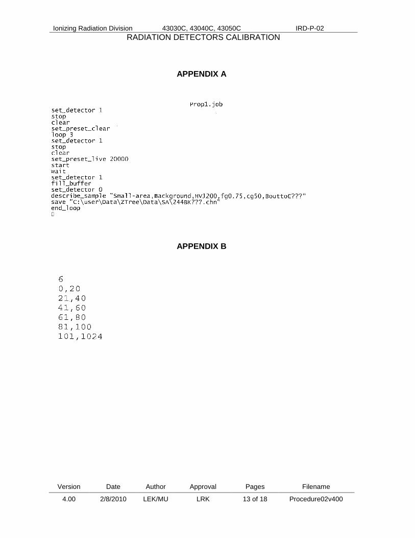
Open file named: prop1.job (see Appendix A for example). - open MAESTRO, go to services, chose job control - chose prop1.job found in the SA folder
(C:\User\Data\ZTree\Data\SA\)
Edit file to establish set-up parameters including:

Ionizing Radiation Division 43030C, 43040C, 43050C IRD-P-02
RADIATION DETECTORS CALIBRATION
Version Date Author Approval Pages Filename
4.00 2/8/2010 LEK/MU LRK 5 of 18 Procedure02v400
- number of sets of measurements (spectra) referred to as loops - elapsed live times for each measurement - counter and sample description - file name, limited to 5 digits - save and exit
Collect spectral data (click OPEN).
Print copies of representative spectra for each source and background to be placed in the alpha-test record binder. Additional copies of standard and background spectra are placed in the small-area maintenance binder.
These images are generated using WinPlots, part of the MAESTRO program. - go to the my computer icon and double click the spectra found in the SA folder
To Change Source
Turn off High Voltage.
Turn off gas flow with black knob.
Turn on air-pressure valve.
Raise top of counter by pulling handle up slowly.
Remove source carefully.
Place next source in center of counter.
Lower counter top slowly.
Turn off air-pressure valve.
Turn on gas with black knob.
Continue as above in introduction of source.
This procedure is repeated without the presence of a source to measure the system background.
To Shut Down
Turn off electronics (high voltage and NIM BIN).
Turn off gas (close black knob, and main valve at the top of bottle).
Take smears of counter and immediate area. Evaluate.
Detector must be open to smear base plate surface.
Close detector.
Make sure air-pressure valve is off. Data Reduction
When data collection is complete, spectra are examined to determine what regions should be set for extrapolation.
Open file called SPECTINC using ZTree (desktop icon), by highlighting file found in SA folder and pressing e, for edit. Change to indicate number of regions as well as the start and finish channels for regions determined above.

Ionizing Radiation Division 43030C, 43040C, 43050C IRD-P-02
RADIATION DETECTORS CALIBRATION
Version Date Author Approval Pages Filename
4.00 2/8/2010 LEK/MU LRK 6 of 18 Procedure02v400
Typically there are 6 regions with channel integrals from 0-20, 21-40, 41-60, 61-80, 81-100,101-1024 (see Appendix B).
Set-up spectra file. File name starts with SA, the next 3 or 4 letters represent the customer name (ex. SANIST).
Highlight file and open by pressing e.
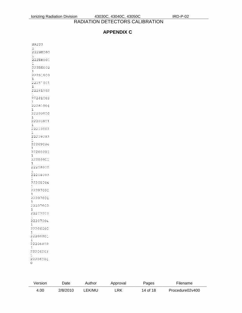
First line indicates name for data file, SA followed by 3 digit day (001-365) of the year (see Appendix C).
The spectra file names are listed. First 3 letters represent the day (001-365) of the year. The next 2 indicate the source being measured, use BK for background. The last three indicate the spectra number as prop1.job assigns them.
Make necessary changes and save.
Run program called NLEVCON.EXE, which executes the data reduction and produces results in counts for each integral region specified above for each spectra.
Open file by pressing x, for execute. - prompt will appear: C:User\Data\ZTree\Data\SA>NLEVCON.EXE - type: < followed by the file name specified above, press enter
Run the data called NLEVEL.EXE which performs the extrapolation automatically.
Open file by pressing x. - press enter, the program will ask a series of questions - the file name requested is the SA, followed by the three number digit
representing the day of the year (ex. SA365, for December 31) - name the set-up file is sf365, and the print file is pf365, replacing 365 by
the number for the actual day
Print out files SA365 and pf365 created and saved by NLEVEL.EXE program in the SA folder.
Conduct extrapolation and calculations by hand using the data found in pf365 and compare to the results produced in SA365.
Record results for the standard in the SA check spreadsheet and check difference from last measurement and from original emission rate the change should be no more than 0.5%.
(2) Large-Area 2 Proportional Counter (all computer files mentioned are located in the LA folder, file names present in the examples in appendices begin with “LA” rather than “SA”) Introduction of Source
Open 5 red clamps holding upper and lower plates together.
Lower base-plate with switch on right side in down position.

Ionizing Radiation Division 43030C, 43040C, 43050C IRD-P-02
RADIATION DETECTORS CALIBRATION
Version Date Author Approval Pages Filename
4.00 2/8/2010 LEK/MU LRK 7 of 18 Procedure02v400
Place source in the center of the counter, handling the source with gloves to prevent possible contamination.
Raise base-plate with switch in up position, close clamps.
Open main valve on the top of the P-10 tank.
Using black knob on the regulator turn on P-10 gas flow as described in general set-up.
Turn on high voltage (750 volts).
When system is completely flushed, reduce flow to approximately 1.5 bubbles per minute on the bubbler.
Use the following settings for the Ortec 575A Dual Amplifier –coarse gain of 2.0 and fine gain of 6.40.
Data Collection
The output of the amplifier is input to the MCA card in the computer which uses a MAESTRO program services.
Initiate job control.
Open file named: prop1.job (see Appendix A for example). - open MAESTRO, go to services, chose job control - chose prop1.job found in the LA folder
(C:\User\Data\ZTree\Data\LA\)
Edit file to establish set-up parameters including: - number of sets of measurements (spectra) referred to as loops
- elapsed live times for each measurement - counter and sample description - file name, limited to 5 digits - save and exit
Collect spectral data (click OPEN).
Print copies of representative spectra for each source and background to be placed in the alpha-test record binder. Additional copies of standard and background spectra are placed in the large-area maintenance binder.
These images are generated using WinPlots, part of the MAESTRO program. - go to the my computer icon and double click the spectra found in the LA folder
To Change Source
Turn off high voltage.
Turn off gas flow at black knob.
Lower base-plate.
Remove source carefully.
Place next source in center of counter.
Raise base-plate.
Clamp counter top slowly.

Ionizing Radiation Division 43030C, 43040C, 43050C IRD-P-02
RADIATION DETECTORS CALIBRATION
Version Date Author Approval Pages Filename
4.00 2/8/2010 LEK/MU LRK 8 of 18 Procedure02v400
Turn on gas with black knob.
Continue as above in introduction of source.
This procedure is repeated without the presence of a source to measure the system background.
To Shut Down
Turn off electronics (high voltage and NIM BIN).
Turn off gas (close black knob and main valve at top of bottle).
Take smears of counter and immediate area. Evaluate.
Detector must be open to smear base plate surface.
Close detector. Data Reduction
When data collection is complete, spectra are examined to determine what regions should be set for extrapolation.
Open file called SPECTINC using ZTree (desktop icon), by highlighting file found in LA folder and pressing e, for edit. Change to indicate number of regions as well as the start and finish channels for regions determined above.
Typically there are 6 regions with channel integrals from 0-20, 21-40, 41-60, 61-80, 81-100,101-1024 (see Appendix B).
Set-up spectra file. File name starts with LA, the next 3 or 4 letters represent the customer name (ex. LANIST).
Highlight file and open by pressing e.
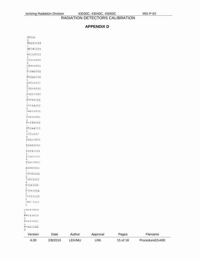
First line indicates name for data file, LA followed by 3 digit day (001-365) of the year (see Appendix C).
The spectra file names are listed. First 3 letters represent the day. The next 2 indicate the source being measured, use BK for background. The last three indicate the spectra number as prop1.job assigns them.
Make necessary changes and save.
Run program called NLEVCON.EXE, which executes the data reduction and produces results in counts for each integral region specified above for each spectra.
Open file by pressing x, for execute. - prompt will appear: C:User\Data\ZTree\Data\LA>NLEVCON.EXE - type: < followed by the file name specified above, press enter
Run the data called NLEVEL.EXE which performs the extrapolation automatically.
Open file by pressing x. - press enter, the program will ask a series of questions
Ionizing Radiation Division 43030C, 43040C, 43050C IRD-P-02
RADIATION DETECTORS CALIBRATION
Version Date Author Approval Pages Filename
4.00 2/8/2010 LEK/MU LRK 9 of 18 Procedure02v400
- the file name requested is the LA, followed by the three number digit representing the day of the year (ex. LA365, for December 31)
- name the set-up file is sf365, and the print file is pf365, replacing 365 by the number for the actual day.
Print out files LA365 and pf365 created and saved by NLEVEL.EXE program in the LA folder.
Conduct extrapolation and calculations by hand using the data found in pf365 and compare to the results produced in LA365.
Record results for the standard in the LA check spreadsheet and check difference from last measurement and from original emission rate the change should be no more than 0.5%.
(3) NIST table, External Counter (all computer files mentioned are located in the NT folder, file names present in the examples in appendices begin with “NT” rather than “SA”) General Set-up and Introduction of Source
Ensure cables between the amplifier and MCA are attached as marked on wall mounted connection panels and that a 50Ω attenuator is connected between the amplifier and the pre-amplifier.
Remove disks protecting the mylar cover mounted over detector.
Place source on table in first position, marked on table, active side down.
Turn on electronics. Data Collection
The output of the amplifier is input to the MCA card in the computer which uses a MAESTRO program services.
Initiate job control.
Open file named: prop1.job (see Appendix A for example).
Edit file to establish set-up parameters including: - number of sets of measurements(spectra) referred to as loops
- elapsed live times for each measurement - counter and sample description - file name, limited to 5 digits, positions should be indicated - save and exit
Collect spectral data (click OPEN).
Print copies of representative spectra for each source (positions 1-5) and background to be placed in the alpha-test record binder. Additional copies of background spectra are placed in the NIST table maintenance binder.
These images are generated using WinPlots which is part of MAESTRO.

Ionizing Radiation Division 43030C, 43040C, 43050C IRD-P-02
RADIATION DETECTORS CALIBRATION
Version Date Author Approval Pages Filename
4.00 2/8/2010 LEK/MU LRK 10 of 18 Procedure02v400
- go to the my computer icon and double click the spectra found in the SA folder
Move source to next position and repeat the data collection process for all 5 positions.
To Change Source
Data is collected for a high level source and a lower level source whose emission rate has been determined by gas proportional counting.
Remove and secure source, place next source on table in first position.
Repeat data collection instructions for each position.
This procedure is repeated without the presence of a source to measure the system background.
To Shut Down
Turn off electronics (NIM BIN).
Take smears of table (do not smear mylar cover) and immediate area. Evaluate.
Replace protective disk over mylar cover. Data Reduction
When data collection is complete, spectra are examined to determine what regions should be set for extrapolation. Open file called SPECTINC, by pressing e, for edit. Change content to indicate number of regions as well as the start and finish channels for regions determined above.
Typically there are 4 regions with channel integrals from 0-60, 61-120, 121-180, 181-1024 (see Appendix B).
Set-up spectra file. File name starts with NT, the next 3 or 4 letters represent the customer name (ex. NTNIST).
Highlight file and open by pressing e.
First line indicates name for data file, NT followed by 3 digit day (001-365) of the year (ex. NT365 for December 31).
The spectra file names are listed. First 2 digits represent position, the next 3 indicate the source being measured, BK and numerical day is used for background, the last three indicate the spectra number as prop1.job assigns them. Make necessary changes and save.
Run program called NLEVCON.EXE, which executes the data reduction and produces results in counts for each integral region specified above for each spectra.
Open file by pressing x, for execute. - prompt will appear: C:User\Data\ZTree\Data\NT>NLEVCON.EXE - type: < followed by the file name specified above, press enter
Ionizing Radiation Division 43030C, 43040C, 43050C IRD-P-02
RADIATION DETECTORS CALIBRATION
Version Date Author Approval Pages Filename
4.00 2/8/2010 LEK/MU LRK 11 of 18 Procedure02v400
Run the program called NLEVEL.EXE which performs the extrapolation automatically.
Open file by pressing x. - press enter, the program will ask a series of questions - the file name requested is the NT, followed by the three digit day of the
year - name the set-up file sf365, and the print file is pf365, replacing 365 by the
number for the actual day.
Print out files NT365 and pf365 saved by program in the NT folder.
Results produced in NT365 are used to determine the ratio of one source to the other and multiplied by the known emission-rate of the lower activity source, to determine the emission-rate of the higher level source.
The data file pf365 is printed and included for informational purposes only. Determination of Uncertainties The basis for the determination of uncertainties associated with alpha-particle calibrations is: Guidelines for Evaluating and Expressing the Uncertainty of NIST Measurement Results by Barry N. Taylor and C. E. Kuyatt, NIST Technical Note 1297, September 1994. Uncertainty components are given below. All uncertainties are type B except for counting statistics and background, which are type A. Significant Uncertainties Counting statistics - this value was obtained from the standard deviation of replicate measurements Background – based on statistical estimate Live-time – obtained by measurements with sources of varying and known activities Extrapolation to zero keV – estimated from largest possible variability in assumed extrapolation functionality Self-absorption and scattering from source and support - estimated from customer stated source thickness and inaccuracies in back-scattering factors The following uncertainties are recognized but are not significant Counter geometry - the values were obtained from estimated mechanical accuracies measurements made on the systems

Ionizing Radiation Division 43030C, 43040C, 43050C IRD-P-02
RADIATION DETECTORS CALIBRATION
Version Date Author Approval Pages Filename
4.00 2/8/2010 LEK/MU LRK 12 of 18 Procedure02v400
Extension and non-uniformity of the sources- this was derived from known limitations in the accuracies of measurements because of source size Scattering in/on detector – estimated from known parameters Transmission through detector (no count) – based on comparisons with standards using other direct measurement methods References 1. The Standardization of Alpha-Particle Sources, L.L. Lucas. Proceedings of the ASTM Conference of Effluent and Environmental Surveillance, July 9-14, 1978, Johnson, Vermont, in ASTM Spec. Tech. Publ. 698, pp. 342-354 (1980). 2. Guidelines for Evaluating and Expressing the Uncertainty of NIST Measurement Results, Barry N. Taylor and Chris Kuyatt. NIST Technical Note 1297, September 1994. 3. Alpha-Particle Calibrations, J. M. Robin Hutchinson. N.B.S. Special Publication 250-5, U.S. Government Printing Office, Washington D.C. 20402-9325 (1987). Records Customer log sheet includes customer name and contact information, date received, kind of source, source number and identification including RS number and test folder number, date calibrated, date returned to customer, copies of the purchase order, shipping documentation, and 364 forms. Alpha test record book includes hard copy of the data, data reduction and related calculations, calibration results, customer calibration spreadsheets, copy of certificate, and the above described log sheet. Computer records include unsigned copies of certificates, spreadsheets used to check standards and customer calibration sources. Filing and Retention All paper copies of customer files are stored in the test folder for that service; test folders are stored in a file cabinet maintained by the calibration staff. All customer-related electronic files are stored either on password-protected calibration-staff desktops or in the “High Dose” folder on the shared network drive. The IRD Quality Manager shall maintain the original and past versions of this IRD Procedure. See Guide IRD-G-01 for additional policies on Procedure maintenance.
Ionizing Radiation Division 43030C, 43040C, 43050C IRD-P-02
RADIATION DETECTORS CALIBRATION
Version Date Author Approval Pages Filename
4.00 2/8/2010 LEK/MU LRK 13 of 18 Procedure02v400
APPENDIX A
APPENDIX B
Ionizing Radiation Division 43030C, 43040C, 43050C IRD-P-02
RADIATION DETECTORS CALIBRATION
Version Date Author Approval Pages Filename
4.00 2/8/2010 LEK/MU LRK 14 of 18 Procedure02v400
APPENDIX C
Ionizing Radiation Division 43030C, 43040C, 43050C IRD-P-02
RADIATION DETECTORS CALIBRATION
Version Date Author Approval Pages Filename
4.00 2/8/2010 LEK/MU LRK 15 of 18 Procedure02v400
APPENDIX D

Ionizing Radiation Division 43030C, 43040C, 43050C IRD-P-02
RADIATION DETECTORS CALIBRATION
Version Date Author Approval Pages Filename
4.00 2/8/2010 LEK/MU LRK 16 of 18 Procedure02v400
APPENDIX E
Table of Uncertainties
Factor
Type A
Uncertainty
(1 ) percent
Type B
Uncertainty
(1 ) percent
Counting statistics
0.1
Background
0.1
Live time
0.1
Extrapolation
0.7
Combined Uncertainties 0.14 0.7 Added In Quadrature Total Combined Uncertainty 1.4 (2 times the sum of the quadratic sum of the two combined uncertainties)

Ionizing Radiation Division 43030C, 43040C, 43050C IRD-P-02
RADIATION DETECTORS CALIBRATION
Version Date Author Approval Pages Filename
4.00 2/8/2010 LEK/MU LRK 17 of 18 Procedure02v400
APPENDIX F

Ionizing Radiation Division 43030C, 43040C, 43050C IRD-P-02
RADIATION DETECTORS CALIBRATION
Version Date Author Approval Pages Filename
4.00 2/8/2010 LEK/MU LRK 18 of 18 Procedure02v400