allgemeine informationen general information
TRANSCRIPT

1-A Hydromot Axialkolbeneinheiten | Axial piston units
SchluckvolumenDisplacement 14 / 18 21 / 28 46 / 50 / 64
Radiale BelastungRadial load Fq max
N[lbf ]
600[135]
1200[270]
3000[675]
Axiale BelastungAxial load F ax max
N[lbf ]
400[90]
950[213]
1500[337]
General information
Product descriptionC series is a family of variable displacement axial piston pumps for use in closed circuits. The displacement is infini-tely variable by means of a tilting swash plate; the oil flow can be reversed over the neutral point. Various controls are available: manual, servo control lever operated, electric etc. Each pump is provided with a charge pump that makes up for internal leakage, maintains a positive pressure in the main circuit and provides oil to the control system. All pumps have maximum pressure relief valves and can be supplied single or tandem version. Different through drive options are availa-ble for auxiliary pump mounting as well as a wide range of options: by-pass valve, pressure filter and others.
Technical features
Drive shaft radial and axial loadsThe drive shaft can stand both radial and axial loads. The maximum permissible loads in the following table are calcu-lated in such a way as to guarantee a service life of at least 80% of the service life of bearings to which no load is applied.
Allgemeine Informationen
ProduktbeschreibungDie Serie C gehört zu der Familie der Axialkolbenpumpen mit variablem Schluckvolumen zum Einsatz in geschlosse-nen Kreisläufen. Das Schluckvolumen wird dabei stufen-los über das Verstellen der Schrägscheibe erreicht. Durch Verdrehen über die Neutralstellung kann der Ölstrom auch umgekehrt werden. Verschiedene Bedienungen sind erhältlich: Manuell, Servomechanisch, Elektrisch, usw. Jede Pumpe hat eine Speisepumpe, die für die interne Leckage verantwortlich ist, für den positiven Druck im Hauptkreis sorgt und die Steuerung mit Öl versorgt. Alle Pumpen sind mit einem Druckbegrenzungsventil ausgestattet und sind als Einzel- sowie Tandempumpen erhältlich. Verschie-denste Ausführungen für den Durchtrieb sind ebenso erhältlich wie eine große Palette von weiteren Optionen (Bypass-Ventil, Druckfilter, usw.).
Technische Eigenschaften
Radiale und axiale Belastungen auf die AntriebswelleDie Antriebswelle wiedersteht sowohl radialen als auch axialen Belastungen. Die maximal zulässigen Belastungen in der folgenden Tabelle wurden so berechnet, dass die Lebensdauer der Lager 80% der Lebensdauer unbelasteter Lager entspricht.
InstallationC series pumps can be installed in every position or direction. For further details contact us.
FluidsUse fluids on mineral oil basis and anticorrosive, antioxidant and wear preventing addition agents (HLP or HM). Viscosity range at operating temperature must be of 15 ÷ 60 mm²/s. For short periods and upon cold start, a max. viscosity of 800 mm²/s is allowed. Viscosities less than 10 mm²/s are not allo-wed. A viscosity range of 10 ÷ 15 mm²/s is allowed for extreme operating conditions and for short periods only.
Operating temperatureThe operating temperature of the oil must be within -25 ºC ÷ 80 ºC [-13 ºF ÷ 176 ºF]. The running of the axial piston unit with oil temperature higher than 80 ºC [176 °F] or lower than - 25 ºC [-13 °F] is not allowed.
MontagePumpen der Serie C können in jede Position und Richtung eingebaut werden. Für weitere Informationen sprechen Sie uns bitte an.
FördermediumVerwenden Sie nur Flüssigkeiten auf Mineralölbasis (HLP oder HM). Die Viskosität muss bei Betriebstemperatur 15 - 60 mm²/s liegen. Für kurze Zeit und bei Kaltstart darf die Viskosität maximal 800 mm²/s sein. Viskosität kleiner 10 mm²/s sind nicht gestattet. Viskosität 10 - 15 mm²/s sind nur bei extremen Einsatzbedingungen und nur für kurze Zeit erlaubt.
BetriebstemperaturDie Betriebstemperatur des Öls muss zwischen -25 °C und 80 °C [-13 °F ÷ 176 °F] liegen. Der Betrieb der Axialkolben-einheit mit einer Öltemperatur außerhalb dieses Bereiches ist nicht gestattet.
1-A Hydromot Axialkolbeneinheiten | Axial piston units
FiltrationIn order to ensure a correct functioning of the unit, the max. permissible contamination level in the circuit is 20/18/15 according to ISO 4406:1999.
Suction pressureThe minimum pressure on the auxiliary pump suction must be of 0.8 bar [11.6 absolute PSI]. On cold starting and for short-term a pressure of 0.5 bar [7.25 PSI] is allowed. In no case inlet pressure can be lower.
Case drain pressureMaximum case drain pressure is 2 bar [29 PSI]. On cold star-ting and for short-term a pressure of 6 bar [86 PSI] is allowed. A higher pressure can damage the main shaft seal or reduce its life.
SealsStandard seals used on our pumps are NBR. In case of use spe-cial fluids please contact us.
Displacement limitingThe pump is equipped with the displacement mechanical limiting device. Displacement limitation is obtained by means of two setting screws which limit the control piston stroke.
Installation and commissioning notes
General rulesThese installation and commissioning specifications are intended for use with C1, C2 and C3 axial piston pumps for closed circuit. Adherence to these recommendations has a decisive effect on the service life of the units with standard internal elements, used with common hydraulic fluids. Care-fully read this rules before installing and commissioning the application. For ports reference see the product catalogue. A standard requirement is that the pump casing must be com-pletely filled with already filtered hydraulic oil before com-missioning or re-commissioning the pump. The casing must remain also filled when operating.
Commissioning or re-commissioning the unit without filling the pump or with too little fluid in it will result in damage or in immediate destruction of the rotating group.
In the following text, we will differentiate between instal-lation position (pump to tank) and installation orientation (pump shaft vertical, horizontal etc.).
The ideal filling orientation is specified after. Only in this posi-tion can complete filling be ensured. On commissioning or re-commissioning, this position should be maintained.
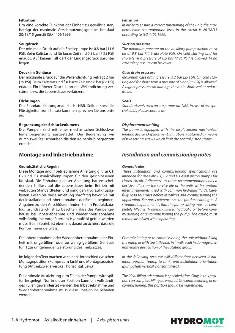
FiltrationUm eine korrekte Funktion der Einheit zu gewährleisten, beträgt der maximale Verschmutzungsgrad im Kreislauf 20/18/15 gemäß ISO 4406:1999.
SaugdruckDer minimale Druck auf die Speisepumpe ist 0,8 bar [11.6 PSI]. Beim Kaltstart und für kurze Zeit sind 0,5 bar [7.25 PSI] erlaubt. Auf keinen Fall darf der Eingangsdruck darunter liegen.
Druck im GehäuseDer maximale Druck auf die Wellendichtung beträgt 2 bar [29 PSI]. Beim Kaltstart und für kurze Zeit sind 6 bar [86 PSI] erlaubt. Ein höherer Druck kann die Wellendichtung zer-stören bzw. die Lebensdauer verkürzen.
DichtungenDas Standarddichtungsmaterial ist NBR. Sollten spezielle Flüssigkeiten zum Einsatz kommen sprechen Sie uns bitte an.
Begrenzung des SchluckvolumensDie Pumpen sind mit einer mechanischen Schluckvo-lumenbegrenzung ausgestattet. Die Begrenzung wir durch zwei Stellschrauben die den Kolbenhub begrenzen erreicht.
Montage und Inbetriebnahme
Grundsätzliche RegelnDiese Montage und Inbetriebnahme Anleitung gilt für C1, C2 und C3 Axialkolbenpumpen für den geschlossenen Kreislauf. Die Einhaltung dieser Anleitung hat entschei-denden Einfluss auf die Lebensdauer beim Betrieb mit verbauten Standardteilen und gängigen Hydraulikflüssig-keiten. Lesen Sie diese Anleitung sorgfältig bevor Sie mit der Installation und Inbetriebnahme der Einheit beginnen. Angaben zu den Anschlüssen finden Sie im Produktkata-log. Grundsätzlich ist zu beachten, dass das Pumpenge-häuse bei Inbetriebnahme und Wiederinbetriebnahme vollständig mit vorgefiltertem Hydrauliköl gefüllt werden muss. Beim Betrieb ist ebenfalls darauf zu achten, dass die Pumpe immer gefüllt ist.
Die Inbetriebnahme oder Wiederinbetriebnahme der Ein-heit mit ungefülltem oder zu wenig gefülltem Gehäuse führt zur umgehenden Zerstörung des Triebsatzes.
Im folgenden Text machen wir einen Unterschied zwischen Montageposition (Pumpe zum Tank) und Montageausrich-tung (Antriebswelle vertikal, horizontal, usw.)
Die optimale Ausrichtung zum Füllen der Pumpe wird spä-ter festgelegt. Nur in dieser Position kann ein vollständi-ges Füllen gewährleistet werden. Bei Inbetriebnahme und Wiederinbetriebnahme muss diese Position beibehalten werden.

1-A Hydromot Axialkolbeneinheiten | Axial piston units
Installation positionThe following installation positions are possible:1. Pump above the tank (above the minimum oil level). Pos-
sible but not recommended.2. Pump alongside the tank (below minimum oil level) or
where the upper point on the unit housing is levelled with the minimum oil level.
3. Pump below the tank (below the minimum oil level).
MontagepositionDie folgenden Montagepositionen sind möglich:1. Pumpe über dem Tank (über dem niedrigsten Ölstand).
Möglich aber nicht empfohlen.2. Pumpe neben dem Tank (unter dem niedrigsten
Ölstand) oder wenn die höchste Stelle der Pumpe sich mit dem niedrigsten Ölstand auf einer Höhe befindet.
3. Pumpe unter dem Tank (unter dem niedrigsten Ölstand).
Dimensioning linesThe minimum absolute pressure in suction line should never be below 0.8 bar. To achieve this, the fluid velocity in the suc-tion line must be kept as low as possible. Moreover, the pres-sure and drain lines should also be dimensioned in such a way to keep the pressure drop across them limited.
Recommended ranges for the fluid velocity in relation to the service are shown in the table below.
The lower the fluid velocity is kept, the more efficient and safe the operation of the pump will be.
Dimensionierung der LeitungenDer Druck in der Saugleitung sollte niemals unter 0,8 bar absolut fallen. Um dies zu erreichen, muss die Strömungs-geschwindigkeit in der Saugleitung so gering wie mög-lich gehalten werden. Darüber hinaus sollten Druck- und Leckageleitungen so dimensioniert sein, dass der Druck-abfall über dieser Grenze bleibt.
Die empfohlenen Strömungsgeschwindigkeiten in Bezug auf die Leitungsart können Sie der Tabelle unten entnehmen.
Je niedriger die Strömungsgeschwindigkeit ist, desto effi-zienter und sicherer ist der Betrieb der Pumpe.
Leitungsart Strömungsgeschwindigkeit
Saugleitung 0,6 - 1,2 m/sec
Leckageleitung 1,5 - 4,0 m/sec
Druckleitung 2,0 - 5,5 m/sec
Line type Fluid velocity
Suction line 0.6 ÷ 1.2 m/sec
Drain line 1.5 ÷ 4.0 m/sec
Pressure line 2.0 ÷ 5.5 m/sec
1-A Hydromot Axialkolbeneinheiten | Axial piston units
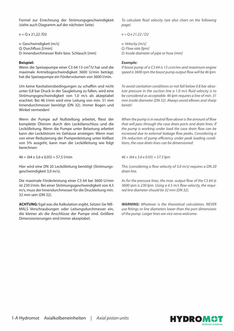
To calculate fluid velocity (see also chart on the following page)
v = Q x 21.22 / D2
v: Velocity [m/s]Q: Flow rate [lpm]D: Inside diameter of pipe or hose [mm]
Example:If boost pump of a C3 64 is 13 ccm/rev and maximum engine speed is 3600 rpm the boost pump output flow will be 46 lpm.
To avoid cavitation conditions or not fall below 0.8 bar abso-lute pressure in the suction line a 1.0 m/s fluid velocity is to be considered as acceptable. 46 lpm requires a line of min. 31 mm inside diameter (DN 32). Always avoid elbows and sharp bends!
When the pump is in neutral flow above is the amount of flow that will pass through the case drain ports and drain lines. If the pump is working under load the case drain flow can be increased due to external leakage flow peaks. Considering a 5% reduction of pump efficiency under peak loading condi-tions, the case drain lines can be dimensioned:
46 + (64 x 3.6 x 0.05) = 57.5 lpm
This (considering a flow velocity of 3.0 m/s) requires a DN 20 drain line.
As for the pressure lines, the max. output flow of the C3 64 @ 3600 rpm is 230 lpm. Using a 4.5 m/s flow velocity, the requi-red line diameter should be 32 mm (DN 32).
WARNING: Whatever is the theoretical calculation, NEVER use fittings or line diameters lower than the port dimensions of the pump. Larger lines are vice versa welcome.
Formel zur Errechnung der Strömungsgeschwindigkeit (siehe auch Diagramm auf der nächsten Seite)
v = Q x 21,22 /D2
v: Geschwindigkeit [m/s]Q: Durchfluss [l/min]D: Innendurchmesser Rohr bzw. Schlauch [mm]
Beispiel:Wenn die Speisepumpe einer C3 64 13 cm³/U hat und die maximale Antriebsgeschwindigkeit 3600 U/min beträgt, hat die Speisepumpe ein Fördervolumen von 3600 l/min.
Um keine Kavitationsbedingungen zu schaffen und nicht unter 0,8 bar Druck in der Saugleitung zu fallen, wird eine Strömungsgeschwindigkeit von 1,0 m/s als akzeptabel erachtet. Bei 46 l/min wird eine Leitung von min. 31 mm Innendurchmesser benötigt (DN 32). Immer Bogen und Winkel vermeiden!
Wenn die Pumpe auf Nullstellung arbeitet, fliest der komplette Ölstrom durch den Leckölanschluss und die Leckölleitung. Wenn die Pumpe unter Belastung arbeitet kann der Leckölstrom im Gehäuse ansteigen. Wenn man von einer Reduzierung der Pumpenleistung unter Volllast von 5% ausgeht, kann man die Leckölleitung wie folgt berechnen:
46 + (64 x 3,6 x 0,05) = 57,5 l/min
Hier wird eine DN 20 Leckölleitung benötigt (Strömungs-geschwindigkeit 3,0 m/s).
Die maximale Förderleistung einer C3 64 bei 3600 U/min ist 230 l/min. Bei einer Strömungsgeschwindigkeit von 4,5 m/s, muss der Innendurchmesser für die Druckleitung min. 32 mm sein (DN 32).
ACHTUNG: Egal was die Kalkulation ergibt, Setzen Sie NIE-MALS Verschraubungen oder Leitungsdurchmesser ein, die kleiner als die Anschlüsse der Pumpe sind. Größere Dimensionierungen sind immer akzeptabel.

1-A Hydromot Axialkolbeneinheiten | Axial piston units
Dur
chflu
ss [l
/min
]Fl
ow [l
pm]
Inne
ndur
chm
esse
r [m
m]
Insi
de d
iam
eter
[mm
]
Strö
mun
gsge
schw
indi
gkei
t [m
/s]
Flow
vel
ocity
[m/s
] Bere
ich
Saug
leitu
ngRa
nge
suct
ion
line
Bere
ich
Dru
ckle
itung
Rang
e pr
essu
re li
ne
To determine the inside diameter of the required line, draw a straight connection on the outer scales between Flow (Q) and Flow velocity (v).
The point of intersection on the center scale corresponds to the inside diameter (D) of the required line.
If the point of intersection is between two nominal sizes, you have to choose the next bigger size.
Flow resistances are not considered.
Der Innendurchmesser der zu bestimmenden Leitung wird ermittelt, indem auf den beiden äußeren Skalen eine gradlinige Verbindung zwischen, Volumenstrom (Q) und Strömungsgeschwindigkeit (v) gezogen wird.
Der Schnittpunkt auf der mittleren Skala (D) entspricht dem Innendurchmesser (DN) der Leitung.
Liegt der Schnittpunkt zwischen zwei Nennweiten, so ist immer die nächst höhere Größe zu wählen.
Durchflusswiderstände sind nicht berücksichtigt.

1-A Hydromot Axialkolbeneinheiten | Axial piston units
First starting / re-startingBefore starting any procedure, it is strictly required that all pipes and hoses in the circuit are pre-flushed and the reservoir filled completely with pre-filtered oil (preferable filter rating for both operations is 4 µm absolute).After the installation is complete and the pump body has been filled (see filling procedure) proceed as follows:
WARNING: Do not operate the control during start-up procedure
1. Connect a 0-600 bar pressure gauge on both “GA“ and “GB“ ports (available only for 50 and 64 displacement).
2. Connect a 0-60 bar pressure gauge on port “P“ port.
3. Check that the suction line and the suction filter are com-pletely filled with oil. If not, fill them and bleed air from suction line. Failing to check can result in pump failure.
4. Start and immediately after, stop the motor or the engine, in such way that the pump only turns for a few turns. Repeat this operation until the pressure gauge on “P“ port reads at least 20÷23 bar.
5. Start the motor or the engine and check that the rea-ding on pressure gauge on port “P“ keeps constant at the required value: For C1, C2 and C3 22÷23 bar (Standard value. Can change in some cases)
6. Stop the engine and proceed with the closed loop flushing (see closed loop flushing procedure).
7. Check for hoses and fitting leaks and perform the machine test under load.
MaintenanceFirst oil change has to be made after approx. 500 hours of ope-ration. Filter element has to be replaced after 50 hours for the first time for preliminary circuit cleaning. Next replacement has to be done every 500 hours. Subsequently change oil every 2000 hours. Such intervals should be reduced when the filter clogging indicator shows that the cartridge is clogged or when the system works in heavily polluted environment.
Inbetriebnahme / WiederinbetriebnahmeVor dem Starten ist unbedingt darauf zu achten, dass alle Rohre und Schläuche im Kreislauf vorgespült und der Tank komplett mit vorgefiltertem Öl gefüllt ist (Filterfeinheit für beide Arbeiten: Vorzugsweise 4 µm absolut).Nachdem die Installation komplett erfolgt ist und das Pum-pengehäuse gefüllt ist (siehe Füllprozedur), die Pumpe wie folgt starten:
ACHTUNG: Während der Inbetriebnahme nicht den Reg-ler der Pumpe betätigen!
1. An beiden Anschlüssen „GA“ und „GB“ (nur für Schluck-volumen 50 und 64 erhältlich) ein Manometer 0-600 bar anschließen.
2. Am Anschluss „P“ ein Manometer 0-60 bar anschlie-ßen.
3. Überprüfen ob die Saugleitung und der Saugfilter komplett mit Öl gefüllt sind. Wenn nicht, dann füllen und die Saugleitung entlüften. Wenn sich Luft in der Saugleitung befindet kann dies zu einem Schaden führen.
4. Direkt nach dem Start den Motor bzw. die Maschine wieder stoppen, die Pumpe darf immer nur wenige Umdrehungen laufen. Diese Vorgehensweise wieder-holen bis das Manometer 20-23 bar anzeigt.
5. Den Motor bzw. die Maschine starten und darauf ach-ten, dass das Manometer am Anschluss „P“ konstant den empfohlen Wert anzeigt: Bei C1, C2 und C3 sind dies 22-23 bar (Standardwert. Kann in manchen Fäl-len abweichen.
6. Den Motor bzw. die Maschine stoppen und mit dem Spülen des geschlossenen Kreislaufes fortfahren (siehe auch Spülen des geschlossenen Kreislaufs).
7. Alle Leitungen und Verschraubungen auf Dichtheit prüfen und die Pumpe unter Belastung testen.
WartungDer erste Ölwechsel sollte nach ca. 500 Betriebsstunden erfolgen. Der Filterelementwechsel sollte zum ersten Mal nach 50 Stunden erfolgen, da dann die Reinigung des Sys-tems abgeschlossen ist. Der Filter sollte danach alle 500 Stunden gewechselt werden; das Öl alle 2000 Stunden. Die Intervalle sollten verkürzt werden, wenn die Verschmut-zungsanzeige des Filters eine Verschmutzung anzeigt oder wenn das System in einer stark verschmutzten Umgebung arbeitet.

1-A Hydromot Axialkolbeneinheiten | Axial piston units
Closed loop flushing procedureAfter the first starting is completed, the closed loop flushing must be done. This procedure applies to brand new machines, after a major maintenance work or when the pressure lines between pump and motor have been changed or disconnec-ted. This procedure is mandatory to remove any presence of contaminant in hoses, pipes and fittings. Both pump and motor will work even if flushing procedure is not performed but the service life of both could be seriously reduce.
To flush the closed loop it must be used an in-line filter with suitable pressure and flow rate rating. The filter must be pre-ferably 4 µm absolute - 10 µm absolute can be used as an alternative.
If the filter has only one possible flow direction, the pump con-trol must be operated to achieve the correct flow direction.
The in-line filter can be mounted at two different positions:
1. Connecting the pressure lines of the motor to the filter.
2. Connecting the filter on the return line before the oil goes back to the pump and by passing the motor by the means of an additional hose (preferable solution).
The flushing can be stopped, when the oil contamination level in the closed loop is at least 18/16/13 or lower according ISO 4406.
WARNING: When two or more motors are connected in par-allel layout to the pump, it is necessary to ensure the correct flushing of each of the circuit sections connecting the motors.
When the flushing is completed, the in-line filter and the even-tual auxiliary hoses must be removed to configure the circuit to the design layout.
After the circuit has been restored to the design layout, the machine can be tested under load and the eventual pressure adjustments and final tests can be done.
Spülen des geschlossenen KreislaufesNachdem die Inbetriebnahme erfolgt ist muss nun der geschlossene Kreislauf gespült werden. Diese Prozedur betrifft neue Maschinen, nach großen Instandhaltungsar-beiten oder wenn Druckleitungen zwischen Pumpe und Motor getauscht oder entfernt wurden. Diese Prozedur muss zwingend durchgeführt werden um etwaige Verun-reinigungen in Schläuchen, Rohren und Verschraubungen zu entfernen. Pumpe und Motor arbeiten auch dann, wenn diese Arbeiten nicht durchgeführt werden. Die Lebens-dauer der Komponenten wird dadurch jedoch verkürzt.
Zum Spülen des Kreislaufes muss ein passender (Druck-bereich und Durchfluss) Leitungsfilter verwendet werden. Bevorzugte Filterfeinheit 4 µm (alternativ 10 µm) absolut.
Wenn der Filter nur eine mögliche Durchflussrichtung besitzt, muss der Pumpenregler betätigt werden um den korrekt Fluss durch den Filter zu gewährleisten.
Der Leitungsfilter kann an zwei verschiedenen Positionen verbaut werden:
1. Den Filter in die Druckleitung des Motors einbauen.
2. Den Filter in die Rücklaufleitung einbauen. Bevor das Öl zurück zur Pumpe geht einen zusätzlichen Schlauch einbauen (bevorzugte Stelle).
Das Spülen kann beendet werden, wenn eine Ölreinheits-klasse von mindestens 18/16/13 oder niedriger gemäß ISO 4406 erreicht ist.
ACHTUNG: Wenn zwei oder mehr Motoren im Parallelbe-trieb arbeiten ist darauf zu achten, dass jede einzelne Sek-tion korrekt gespült wird.
Wenn das Spülen abgeschlossen ist, muss der Filter und eventuelle zusätzliche Schläuche wieder aus dem Kreislauf entfernt werden.
Nachdem das System auf seinen ursprünglichen Zustand zurück gebaut wurde, kann nun die Maschine unter Belastung getestet werden und eventuelle Druck- und Abschlusstest durchgeführt werden.

4-A Hydromot Axialkolbeneinheiten | Axial piston units
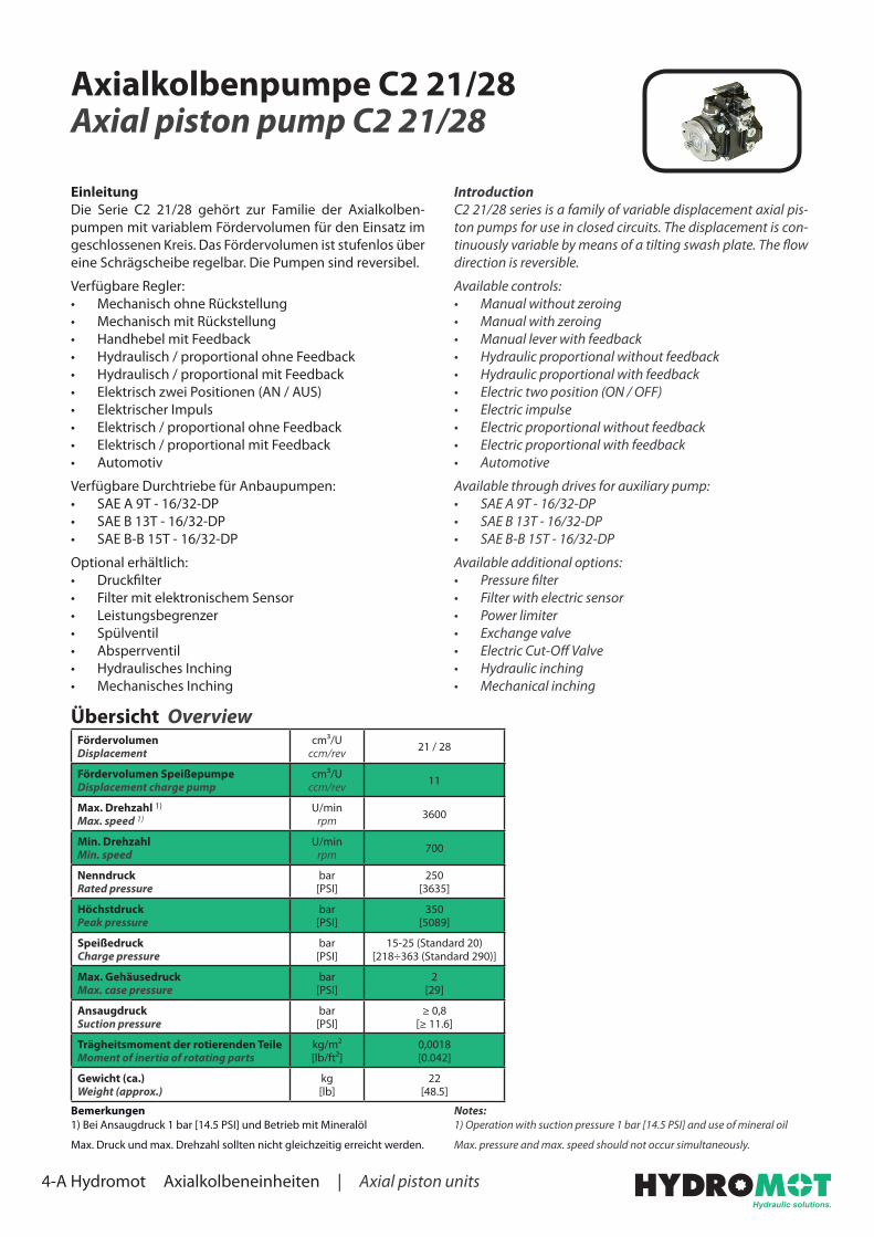
Axialkolbenpumpe C2 21/28Axial piston pump C2 21/28
IntroductionC2 21/28 series is a family of variable displacement axial pis-ton pumps for use in closed circuits. The displacement is con-tinuously variable by means of a tilting swash plate. The flow direction is reversible.
Available controls:• Manual without zeroing• Manual with zeroing• Manual lever with feedback• Hydraulic proportional without feedback• Hydraulic proportional with feedback• Electric two position (ON / OFF)• Electric impulse• Electric proportional without feedback• Electric proportional with feedback• Automotive
Available through drives for auxiliary pump:• SAE A 9T - 16/32-DP• SAE B 13T - 16/32-DP• SAE B-B 15T - 16/32-DP
Available additional options:• Pressure filter• Filter with electric sensor• Power limiter• Exchange valve• Electric Cut-Off Valve• Hydraulic inching• Mechanical inching
EinleitungDie Serie C2 21/28 gehört zur Familie der Axialkolben-pumpen mit variablem Fördervolumen für den Einsatz im geschlossenen Kreis. Das Fördervolumen ist stufenlos über eine Schrägscheibe regelbar. Die Pumpen sind reversibel.
Verfügbare Regler:• Mechanisch ohne Rückstellung• Mechanisch mit Rückstellung• Handhebel mit Feedback• Hydraulisch / proportional ohne Feedback • Hydraulisch / proportional mit Feedback• Elektrisch zwei Positionen (AN / AUS)• Elektrischer Impuls• Elektrisch / proportional ohne Feedback • Elektrisch / proportional mit Feedback• Automotiv
Verfügbare Durchtriebe für Anbaupumpen:• SAE A 9T - 16/32-DP• SAE B 13T - 16/32-DP• SAE B-B 15T - 16/32-DP
Optional erhältlich:• Druckfilter• Filter mit elektronischem Sensor• Leistungsbegrenzer• Spülventil• Absperrventil• Hydraulisches Inching• Mechanisches Inching
Übersicht OverviewFördervolumenDisplacement
cm³/Uccm/rev 21 / 28
Fördervolumen SpeißepumpeDisplacement charge pump
cm³/Uccm/rev 11
Max. Drehzahl 1)
Max. speed 1)U/min
rpm 3600
Min. DrehzahlMin. speed
U/minrpm 700
NenndruckRated pressure
bar[PSI]
250[3635]
HöchstdruckPeak pressure
bar[PSI]
350[5089]
SpeißedruckCharge pressure
bar[PSI]
15-25 (Standard 20)[218÷363 (Standard 290)]
Max. GehäusedruckMax. case pressure
bar[PSI]
2[29]
AnsaugdruckSuction pressure
bar[PSI]
≥ 0,8[≥ 11.6]
Trägheitsmoment der rotierenden TeileMoment of inertia of rotating parts
kg/m²[lb/ft²]
0,0018[0.042]
Gewicht (ca.)Weight (approx.)
kg[lb]
22[48.5]
Notes:1) Operation with suction pressure 1 bar [14.5 PSI] and use of mineral oil
Max. pressure and max. speed should not occur simultaneously.
Bemerkungen1) Bei Ansaugdruck 1 bar [14.5 PSI] und Betrieb mit Mineralöl
Max. Druck und max. Drehzahl sollten nicht gleichzeitig erreicht werden.
4-A Hydromot Axialkolbeneinheiten | Axial piston units
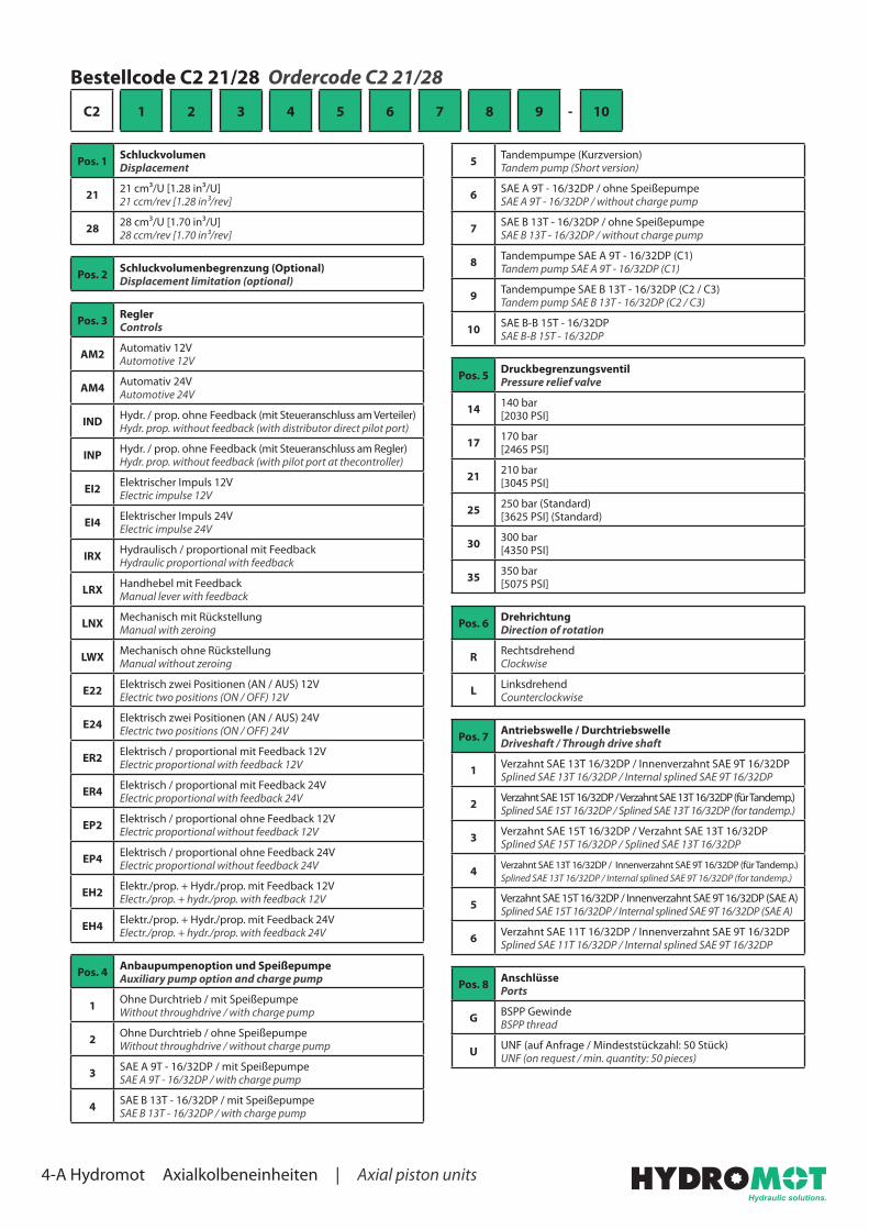
Bestellcode C2 21/28 Ordercode C2 21/28
C2 1 2 3 4 5 6 7 8 9 - 10
Pos. 1 SchluckvolumenDisplacement
21 21 cm³/U [1.28 in³/U]21 ccm/rev [1.28 in³/rev]
28 28 cm³/U [1.70 in³/U]28 ccm/rev [1.70 in³/rev]
Pos. 2 Schluckvolumenbegrenzung (Optional)Displacement limitation (optional)
Pos. 3 ReglerControls
AM2 Automativ 12VAutomotive 12V
AM4 Automativ 24VAutomotive 24V
IND Hydr. / prop. ohne Feedback (mit Steueranschluss am Verteiler)Hydr. prop. without feedback (with distributor direct pilot port)
INP Hydr. / prop. ohne Feedback (mit Steueranschluss am Regler)Hydr. prop. without feedback (with pilot port at thecontroller)
EI2 Elektrischer Impuls 12VElectric impulse 12V
EI4 Elektrischer Impuls 24VElectric impulse 24V
IRX Hydraulisch / proportional mit FeedbackHydraulic proportional with feedback
LRX Handhebel mit FeedbackManual lever with feedback
LNX Mechanisch mit RückstellungManual with zeroing
LWX Mechanisch ohne RückstellungManual without zeroing
E22 Elektrisch zwei Positionen (AN / AUS) 12VElectric two positions (ON / OFF) 12V
E24 Elektrisch zwei Positionen (AN / AUS) 24VElectric two positions (ON / OFF) 24V
ER2 Elektrisch / proportional mit Feedback 12VElectric proportional with feedback 12V
ER4 Elektrisch / proportional mit Feedback 24VElectric proportional with feedback 24V
EP2 Elektrisch / proportional ohne Feedback 12VElectric proportional without feedback 12V
EP4 Elektrisch / proportional ohne Feedback 24VElectric proportional without feedback 24V
EH2 Elektr./prop. + Hydr./prop. mit Feedback 12VElectr./prop. + hydr./prop. with feedback 12V
EH4 Elektr./prop. + Hydr./prop. mit Feedback 24VElectr./prop. + hydr./prop. with feedback 24V
Pos. 4 Anbaupumpenoption und SpeißepumpeAuxiliary pump option and charge pump
1 Ohne Durchtrieb / mit SpeißepumpeWithout throughdrive / with charge pump
2 Ohne Durchtrieb / ohne SpeißepumpeWithout throughdrive / without charge pump
3 SAE A 9T - 16/32DP / mit SpeißepumpeSAE A 9T - 16/32DP / with charge pump
4 SAE B 13T - 16/32DP / mit SpeißepumpeSAE B 13T - 16/32DP / with charge pump
5 Tandempumpe (Kurzversion)Tandem pump (Short version)
6 SAE A 9T - 16/32DP / ohne SpeißepumpeSAE A 9T - 16/32DP / without charge pump
7 SAE B 13T - 16/32DP / ohne SpeißepumpeSAE B 13T - 16/32DP / without charge pump
8 Tandempumpe SAE A 9T - 16/32DP (C1)Tandem pump SAE A 9T - 16/32DP (C1)
9 Tandempumpe SAE B 13T - 16/32DP (C2 / C3)Tandem pump SAE B 13T - 16/32DP (C2 / C3)
10 SAE B-B 15T - 16/32DPSAE B-B 15T - 16/32DP
Pos. 5 DruckbegrenzungsventilPressure relief valve
14 140 bar[2030 PSI]
17 170 bar[2465 PSI]
21 210 bar[3045 PSI]
25 250 bar (Standard)[3625 PSI] (Standard)
30 300 bar[4350 PSI]
35 350 bar[5075 PSI]
Pos. 6 DrehrichtungDirection of rotation
R RechtsdrehendClockwise
L LinksdrehendCounterclockwise
Pos. 7 Antriebswelle / DurchtriebswelleDriveshaft / Through drive shaft
1 Verzahnt SAE 13T 16/32DP / Innenverzahnt SAE 9T 16/32DPSplined SAE 13T 16/32DP / Internal splined SAE 9T 16/32DP
2 Verzahnt SAE 15T 16/32DP / Verzahnt SAE 13T 16/32DP (für Tandemp.)Splined SAE 15T 16/32DP / Splined SAE 13T 16/32DP (for tandemp.)
3 Verzahnt SAE 15T 16/32DP / Verzahnt SAE 13T 16/32DPSplined SAE 15T 16/32DP / Splined SAE 13T 16/32DP
4 Verzahnt SAE 13T 16/32DP / Innenverzahnt SAE 9T 16/32DP (für Tandemp.)Splined SAE 13T 16/32DP / Internal splined SAE 9T 16/32DP (for tandemp.)
5 Verzahnt SAE 15T 16/32DP / Innenverzahnt SAE 9T 16/32DP (SAE A)Splined SAE 15T 16/32DP / Internal splined SAE 9T 16/32DP (SAE A)
6 Verzahnt SAE 11T 16/32DP / Innenverzahnt SAE 9T 16/32DPSplined SAE 11T 16/32DP / Internal splined SAE 9T 16/32DP
Pos. 8 AnschlüssePorts
G BSPP GewindeBSPP thread
U UNF (auf Anfrage / Mindeststückzahl: 50 Stück)UNF (on request / min. quantity: 50 pieces)

4-A Hydromot Axialkolbeneinheiten | Axial piston units
Pos. 9 Zusätzliche Optionen 1Additional options 1
00 Ohne OptionenWithout options
AC C. T. Verteilung (Schrägscheiben Motor)C. T. distribution (motor swash plate)
BP BypassBypass
FI FilterFilter
FE Filter mit elektrischem SensorFilter with electric sensor
FR Filter extern montiertRemote mounted filter
01 LeistungsbegrenzerPower limiter
P1 Absperrventil elektrisch 12VElectric Cut-Off valve 12V
P2 Absperrventil elektrisch 24VElectric Cut-Off valve 24V
VS SpülventilFlushing valve
II Hydraulisches InchingHydraulic inching
IM Mechanisches InchingMechanical inching
Pos. 10 Zusätzliche Optionen 2Additional options 2
Entfällt wenn nicht benötigt / sonst siehe Pos. 9Omit if not required / otherwise see pos. 9
4-A Hydromot Axialkolbeneinheiten | Axial piston units
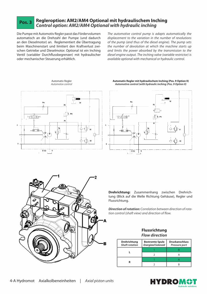
Pos. 3 Regleroption: AM2/AM4 Optional mit hydraulischem InchingControl option: AM2/AM4 Optional with hydraulic inching
The automotive control pump is adapts automatically the displacement to the variation in the number of revolutions of the pump (and thus of the diesel engine). The pump sets the number of devolution at which the machine starts up and limits the power absorbed by the transmission to the diesel engine output. The inching valve (variable restrictor) is available optional with mechanical or hydraulic control.
Die Pumpe mit Automotiv Regler passt das Fördervolumen automatisch an die Drehzahl der Pumpe (und dadurch an den Dieselmotor) an. Reglementiert die Übertragung beim Maschinenstart und limitiert den Kraftverlust zwi-schen Getriebe und Dieselmotor. Optional ist ein Inching Ventil (variabler Durchflussbegrenzer) mit hydraulischer oder mechanischer Steuerung erhältlich.
DrehrichtungShaft rotation
Bestromte SpuleEnergized Solenoid
DruckanschlussPressure port
L1 B
2 A
R1 A
2 B
Flussrichtung Flow direction
Automativ ReglerAutomotov control
Automativ Regler mit hydraulischem Inching (Pos. 9 Option II)Automotive control (with hydraulic inching (Pos. 9 Option II)
Drehrichtung: Zusammenhang zwischen Drehrich-tung (Blick auf die Welle Richtung Gehäuse), Regler und Flussrichtung.
Direction of rotation: Correlation between direction of rota-tion control (shaft view) and direction of flow.

4-A Hydromot Axialkolbeneinheiten | Axial piston units
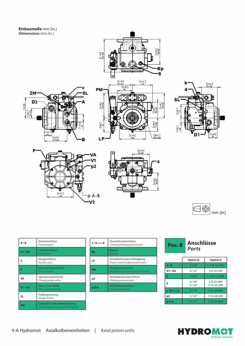
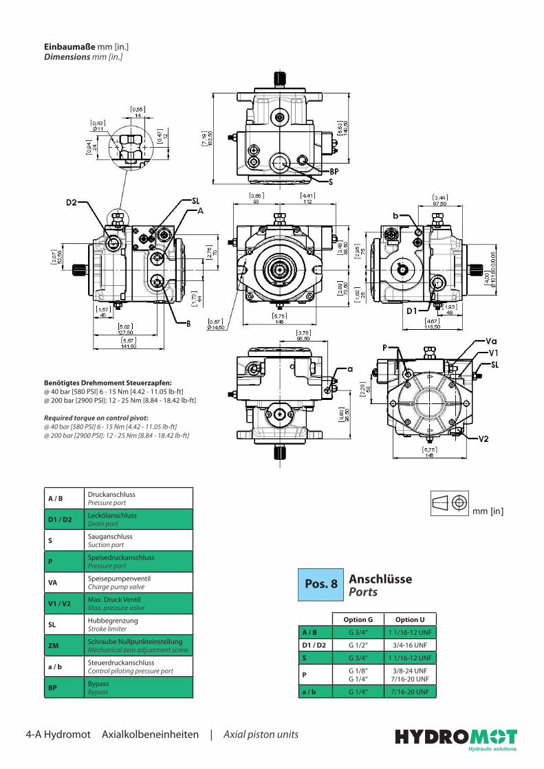
Einbaumaße mm [in.]Dimensions mm [in.]
A / B DruckanschlussPressure port
D1 / D2 LeckölanschlussDrain port
S SauganschlussSuction port
P SpeisedruckanschlussPressure port
VA SpeisepumpenventilCharge pump valve
V1 / V2 Max. Druck VentilMax. pressure valve
SL HubbegrenzungStroke limiter
ZM Schraube NullpunkteinstellungMechanical zero adjustment screw
Pos. 8 Anschlüsse Ports
Option G Option U
A / B G 3/4“ 1 1/16-12 UNF
D1 / D2 G 1/2“ 3/4-16 UNF
S G 3/4“ 1 1/16-12 UNF
P G 1/8“G 1/4“
3/8-24 UNF7/16-20 UNF
a / b / c / d G 1/4“ 7/16-20 UNF
PI G 1/8“ 3/8-24 UNF
p2 G 1/4“ 7/16-20 UNF
p A-B G 1/4“ 7/16-20 UNF
a / b / c / d SteuerdruckanschlussControl piloting pressure port
Bp BypassBypass
PI Inching EingangInching in
LP Einstellschraube KraftreglungPower control adjustment screw
PM Regulierung AnlaufMachine start-up regulation screw
P1R Einstellschraube Min. SteuerdruckControl piloting pressure port
p2 VorsteuerdruckanschlussPiloting pressure port
p A-B HochdruckanschlussHigh pressure port
mm [in]
4-A Hydromot Axialkolbeneinheiten | Axial piston units
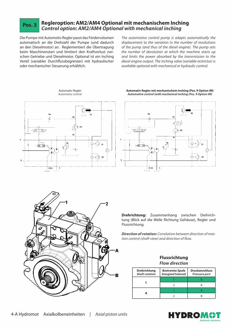
Pos. 3 Regleroption: AM2/AM4 Optional mit mechanischem InchingControl option: AM2/AM4 Optional with mechanical inching
The automotive control pump is adapts automatically the displacement to the variation in the number of revolutions of the pump (and thus of the diesel engine). The pump sets the number of devolution at which the machine starts up and limits the power absorbed by the transmission to the diesel engine output. The inching valve (variable restrictor) is available optional with mechanical or hydraulic control.
Die Pumpe mit Automotiv Regler passt das Fördervolumen automatisch an die Drehzahl der Pumpe (und dadurch an den Dieselmotor) an. Reglementiert die Übertragung beim Maschinenstart und limitiert den Kraftverlust zwi-schen Getriebe und Dieselmotor. Optional ist ein Inching Ventil (variabler Durchflussbegrenzer) mit hydraulischer oder mechanischer Steuerung erhältlich.
DrehrichtungShaft rotation
Bestromte SpuleEnergized Solenoid
DruckanschlussPressure port
L1 B
2 A
R1 A
2 B
Flussrichtung Flow direction
Automativ ReglerAutomotov control
Automativ Regler mit mechanischem Inching (Pos. 9 Option IM)Automotive control (with mechanical inching (Pos. 9 Option IM)
Drehrichtung: Zusammenhang zwischen Drehrich-tung (Blick auf die Welle Richtung Gehäuse), Regler und Flussrichtung.
Direction of rotation: Correlation between direction of rota-tion control (shaft view) and direction of flow.
4-A Hydromot Axialkolbeneinheiten | Axial piston units
Einbaumaße mm [in.]Dimensions mm [in.]
A / B DruckanschlussPressure port
D1 / D2 LeckölanschlussDrain port
S SauganschlussSuction port
P SpeisedruckanschlussPressure port
VA SpeisepumpenventilCharge pump valve
V1 / V2 Max. Druck VentilMax. pressure valve
SL HubbegrenzungStroke limiter
ZM Schraube NullpunkteinstellungMechanical zero adjustment screw
Pos. 8 Anschlüsse Ports
Option G Option U
A / B G 3/4“ 1 1/16-12 UNF
D1 / D2 G 1/2“ 3/4-16 UNF
S G 3/4“ 1 1/16-12 UNF
P G 1/8“G 1/4“
3/8-24 UNF7/16-20 UNF
a / b / c / d G 1/4“ 7/16-20 UNF
p2 G 1/4“ 7/16-20 UNF
p A-B G 1/4“ 7/16-20 UNF
a / b / c / d SteuerdruckanschlussControl piloting pressure port
Bp BypassBypass
LP Einstellschraube KraftreglungPower control adjustment screw
PM Regulierung AnlaufMachine start-up regulation screw
p2 VorsteuerdruckanschlussPiloting pressure port
p A-B HochdruckanschlussHigh pressure port
mm [in]

4-A Hydromot Axialkolbeneinheiten | Axial piston units
Pos. 3 Regleroption: IND Control option: IND
The pump displacement is proportional to the pilot pressure on “a“ or “b“ piloting ports, which also affect flow direction. Feeding pressure to the control joystick can be provided by charge pressure from P port. The pilot pressure must then be controlled by joystick or by a pressure reducing valve (not supplied).
Das Fördervolumen der Pumpe ist proportional zum Steu-erdruck an den Steueranschlüssen „a“ oder „b“, die auch die Flussrichtung bestimmen. Der Speisedruck zum Joy-stick kann vom Anschluss P entnommen werden. Dann muss der Steuerdruck durch den Joystick selbst oder durch ein Druckminderventil (wird nicht mitgeliefert) geregelt werden.
18 [261]
16 [232]14 [203]
12 [174]10 [145]
8 [116]6 [87]
4 [58]2 [29]
0 [0]-2 [-29]
-4 [-58]-6 [-87]
-8 [-116]-10 [-145]
-12 [-174]-14 [-203]-16 [-232]
-18 [-261]
Dru
ck P
ress
ure
bar [
PSI]
Vg/Vg max%
-100 -50 0 50 100
Pilot pressure: 4÷16 bar [58÷232 PSI] at ports a and bStart of control: 4 bar [58 PSI]End of control: 16 bar [232 PSI] max. displacementMax. pressure: 30 bar [435 PSI]
Steuerdruck: 4-16 bar [58-232 PSI] am Anschluss a + bReglerstart: 4 bar [58 PSI]Regleranschlag: 16 bar [232 PSI] max. FördervolumenMax. Druck: 30 bar [435 PSI]
DrehrichtungShaft rotation
SteueranschlussPilot port
DruckanschlussPressure port
Ra A
b B
La B
b A
Flussrichtung Flow direction
Drehrichtung: Zusammenhang zwischen Drehrich-tung (Blick auf die Welle Richtung Gehäuse), Regler und Flussrichtung.
Direction of rotation: Correlation between direction of rota-tion control (shaft view) and direction of flow.

4-A Hydromot Axialkolbeneinheiten | Axial piston units
Einbaumaße mm [in.]Dimensions mm [in.]
mm [in]
Pos. 8 Anschlüsse Ports
Option G Option U
A / B G 3/4“ 1 1/16-12 UNF
D1 / D2 G 1/2“ 3/4-16 UNF
S G 3/4“ 1 1/16-12 UNF
P G 1/8“G 1/4“
3/8-24 UNF7/16-20 UNF
a / b G 1/4“ 7/16-20 UNF
A / B DruckanschlussPressure port
D1 / D2 LeckölanschlussDrain port
S SauganschlussSuction port
P SpeisedruckanschlussPressure port
VA SpeisepumpenventilCharge pump valve
V1 / V2 Max. Druck VentilMax. pressure valve
SL HubbegrenzungStroke limiter
ZM Schraube NullpunkteinstellungMechanical zero adjustment screw
a / b SteuerdruckanschlussControl piloting pressure port
BP BypassBypass
4-A Hydromot Axialkolbeneinheiten | Axial piston units
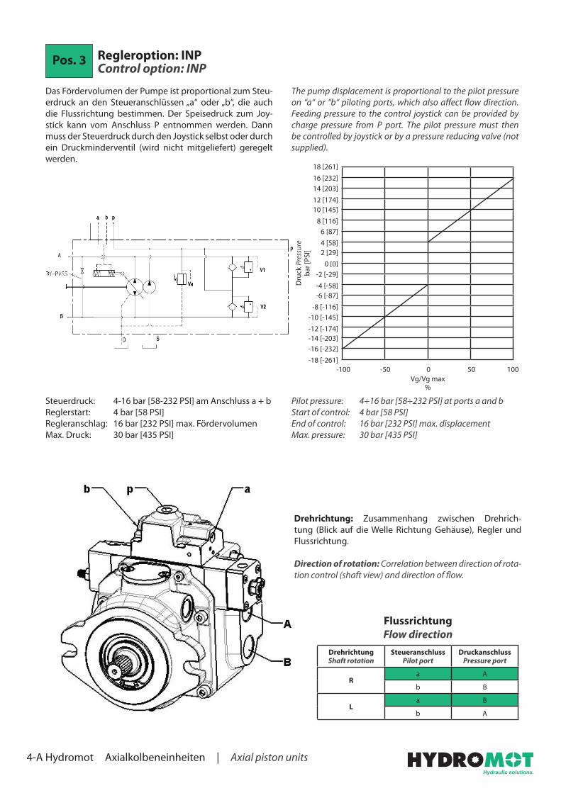
Pos. 3 Regleroption: INP Control option: INP
The pump displacement is proportional to the pilot pressure on “a“ or “b“ piloting ports, which also affect flow direction. Feeding pressure to the control joystick can be provided by charge pressure from P port. The pilot pressure must then be controlled by joystick or by a pressure reducing valve (not supplied).
Das Fördervolumen der Pumpe ist proportional zum Steu-erdruck an den Steueranschlüssen „a“ oder „b“, die auch die Flussrichtung bestimmen. Der Speisedruck zum Joy-stick kann vom Anschluss P entnommen werden. Dann muss der Steuerdruck durch den Joystick selbst oder durch ein Druckminderventil (wird nicht mitgeliefert) geregelt werden.
18 [261]
16 [232]14 [203]
12 [174]10 [145]
8 [116]6 [87]
4 [58]2 [29]
0 [0]-2 [-29]
-4 [-58]-6 [-87]
-8 [-116]-10 [-145]
-12 [-174]-14 [-203]-16 [-232]
-18 [-261]
Dru
ck P
ress
ure
bar [
PSI]
Vg/Vg max%
-100 -50 0 50 100
Pilot pressure: 4÷16 bar [58÷232 PSI] at ports a and bStart of control: 4 bar [58 PSI]End of control: 16 bar [232 PSI] max. displacementMax. pressure: 30 bar [435 PSI]
Steuerdruck: 4-16 bar [58-232 PSI] am Anschluss a + bReglerstart: 4 bar [58 PSI]Regleranschlag: 16 bar [232 PSI] max. FördervolumenMax. Druck: 30 bar [435 PSI]
DrehrichtungShaft rotation
SteueranschlussPilot port
DruckanschlussPressure port
Ra A
b B
La B
b A
Flussrichtung Flow direction
Drehrichtung: Zusammenhang zwischen Drehrich-tung (Blick auf die Welle Richtung Gehäuse), Regler und Flussrichtung.
Direction of rotation: Correlation between direction of rota-tion control (shaft view) and direction of flow.

4-A Hydromot Axialkolbeneinheiten | Axial piston units
Einbaumaße mm [in.]Dimensions mm [in.]
mm [in]
Pos. 8 Anschlüsse Ports
Option G Option U
A / B G 3/4“ 1 1/16-12 UNF
D1 / D2 G 1/2“ 3/4-16 UNF
S G 3/4“ 1 1/16-12 UNF
P G 1/8“G 1/4“
3/8-24 UNF7/16-20 UNF
a / b G 1/4“ 7/16-20 UNF
p1 G 1/4“ 7/16-20 UNF
A / B DruckanschlussPressure port
D1 / D2 LeckölanschlussDrain port
S SauganschlussSuction port
P SpeisedruckanschlussPressure port
VA SpeisepumpenventilCharge pump valve
V1 / V2 Max. Druck VentilMax. pressure valve
SL HubbegrenzungStroke limiter
ZM Schraube NullpunkteinstellungMechanical zero adjustment screw
a / b SteuerdruckanschlussControl piloting pressure port
BP BypassBypass
p1 SpeisedruckanschlussPressure port

4-A Hydromot Axialkolbeneinheiten | Axial piston units
Pos. 3 Regleroption: EI2/EI4 Control option: EI2/EI4
Impulse control where the the displacement of the pump depends on the number of inputs of current to one of the two proportional solenoids. The servocontrol is without zeroing spring, therefore the piston of the servocontrol stays in the position until a new input of current is fed to the solenoids.Flow direction depends on which solenoid is energized. Stan-dard solenoids are ON/OFF 24V DC max. current 1A or 12V DC max. current 2A.
Impulssteuerung bei der das Fördervolumen der Pumpe davon abhängt wie stark eine der beiden Magnetspulen bestromt wird. Bei diesem Regler verbleibt der Kolben in seiner Stellung, bis eine der beiden Magnetspulen einen neuen elektrischen Impuls bekommt.Die Drehrichtung hängt davon ab welche Magnetspule bestromt wird. Standard Magnetspulen sind 24V DC (max. 1A) oder 12V DC (max. 2A).
DrehrichtungShaft rotation
Bestromte SpuleEnergized Solenoid
DruckanschlussPressure port
L1 B
2 A
R1 A
2 A
Flussrichtung Flow direction
Drehrichtung: Zusammenhang zwischen Drehrich-tung (Blick auf die Welle Richtung Gehäuse), Regler und Flussrichtung.
Direction of rotation: Correlation between direction of rota-tion control (shaft view) and direction of flow.

4-A Hydromot Axialkolbeneinheiten | Axial piston units
Einbaumaße mm [in.]Dimensions mm [in.]
mm [in]A / B Druckanschluss
Pressure port
D1 / D2 LeckölanschlussDrain port
S SauganschlussSuction port
P SpeisedruckanschlussPressure port
VA SpeisepumpenventilCharge pump valve
V1 / V2 Max. Druck VentilMax. pressure valve
SL HubbegrenzungStroke limiter
ZM Schraube NullpunkteinstellungMechanical zero adjustment screw
a / b SteuerdruckanschlussControl piloting pressure port
p1 DruckanschlussPressure port
BP BypassBypass
Pos. 8 Anschlüsse Ports
Option G Option U
A / B G 3/4“ 1 1/16-12 UNF
D1 / D2 G 1/2“ 3/4-16 UNF
S G 3/4“ 1 1/16-12 UNF
P G 1/8“G 1/4“
3/8-24 UNF7/16-20 UNF
a / b G 1/4“ 7/16-20 UNF
p1 G 1/4“ 7/16-20 UNF

4-A Hydromot Axialkolbeneinheiten | Axial piston units
Pos. 3 Regleroption: IRX Control option: IRX
The pump displacement is proportional to the pilot pressure on “a“ or “b“ piloting ports, which also affect flow direction. Piloting can be provided by charge pressure from port “P“. The piloting pressure will then have to be controlled by a joystick or by a pressure reducing valve (not supplied).
Das Fördervolumen der Pumpe ist proportional zum Steu-erdruck an den Steueranschlüssen „a“ oder „b“, die auch die Flussrichtung bestimmen. Der Speisedruck kann vom Anschluss P entnommen werden. Dann muss der Steuer-druck durch den Joystick selbst oder durch ein Druckmin-derventil (wird nicht mitgeliefert) geregelt werden.
16 [232]14 [203]
12 [174]10 [145]
8 [116]6 [87]
4 [58]2 [29]
0 [0]-2 [-29]
-4 [-58]-6 [-87]
-8 [-116]-10 [-145]
-12 [-174]-14 [-203]-16 [-232]
Dru
ck P
ress
ure
bar [
PSI]
Vg/Vg max%
-100 -50 0 50 100
Pilot pressure: 6÷16 bar [87÷232 PSI] at ports a and bStart of control: 6 bar [87 PSI]End of control: 16 bar [232 PSI] max. displacementMax. pressure: 30 bar [435 PSI]
Steuerdruck: 6-16 bar [87-232 PSI] am Anschluss a + bReglerstart: 6 bar [87 PSI]Regleranschlag: 16 bar [232 PSI] max. FördervolumenMax. Druck: 30 bar [435 PSI]
DrehrichtungShaft rotation
SteuerdruckPiloting pressure
DruckanschlussPressure port
La B
b A
Ra A
b B
Flussrichtung Flow direction
Drehrichtung: Zusammenhang zwischen Drehrich-tung (Blick auf die Welle Richtung Gehäuse), Regler und Flussrichtung.
Direction of rotation: Correlation between direction of rota-tion control (shaft view) and direction of flow.

4-A Hydromot Axialkolbeneinheiten | Axial piston units
Einbaumaße mm [in.]Dimensions mm [in.]
mm [in]
Pos. 8 Anschlüsse Ports
Option G Option U
A / B G 3/4“ 1 1/16-12 UNF
D1 / D2 G 1/2“ 3/4-16 UNF
S G 3/4“ 1 1/16-12 UNF
P G 1/8“G 1/4“
3/8-24 UNF7/16-20 UNF
a / b G 1/4“ 7/16-20 UNF
c / d G 1/8“ 3/8-24 UNF
A / B DruckanschlussPressure port
D1 / D2 LeckölanschlussDrain port
S SauganschlussSuction port
P SpeisedruckanschlussPressure port
VA SpeisepumpenventilCharge pump valve
V1 / V2 Max. Druck VentilMax. pressure valve
SL HubbegrenzungStroke limiter
ZM Schraube NullpunkteinstellungMechanical zero adjustment screw
a / b / c / d SteuerdruckanschlussControl piloting pressure port
BP BypassBypass

4-A Hydromot Axialkolbeneinheiten | Axial piston units
Pos. 3 Regleroption: LRX Control option: LRX
The displacement of the pump is directly proportional to the angle of the lever. The diagram below shows the relation bet-ween angle and displacement.
Das Fördervolumen der Pumpe verhält sich proportional zum Winkel des Hebels. Das Diagramm unten zeigt das Verhältnis zwischen Winkel und Fördervolumen.
DrehrichtungShaft rotation
DrehrichtungControl rotation
DruckanschlussPressure port
L1 A
2 B
R1 B
2 A
Flussrichtung Flow direction
30
20
10
0
-10
-20
-30
Win
kel A
ngle
[°
]
Vg/Vg max%
-100 -50 0 50 100
Drehrichtung: Zusammenhang zwischen Drehrich-tung (Blick auf die Welle Richtung Gehäuse), Regler und Flussrichtung.
Direction of rotation: Correlation between direction of rota-tion control (shaft view) and direction of flow.

4-A Hydromot Axialkolbeneinheiten | Axial piston units
Einbaumaße mm [in.]Dimensions mm [in.]
mm [in]
Pos. 8 Anschlüsse Ports
Option G Option U
A / B G 3/4“ 1 1/16-12 UNF
D1 / D2 G 1/2“ 3/4-16 UNF
S G 3/4“ 1 1/16-12 UNF
P G 1/8“G 1/4“
3/8-24 UNF7/16-20 UNF
a / b G 1/4“ 7/16-20 UNF
A / B DruckanschlussPressure port
D1 / D2 LeckölanschlussDrain port
S SauganschlussSuction port
P SpeisedruckanschlussPressure port
VA SpeisepumpenventilCharge pump valve
V1 / V2 Max. Druck VentilMax. pressure valve
SL HubbegrenzungStroke limiter
ZM Schraube NullpunkteinstellungMechanical zero adjustment screw
a / b SteuerdruckanschlussControl piloting pressure port
BP BypassBypass
Benötigtes Drehmoment Hebel:0,6 - 1,2 Nm [.44 - .88 lb-ft]Max. Drehmoment Hebel:3 Nm [2.21 lb-ft]
Required torque on control lever:0.6÷1.2 Nm [.44÷.88 lb-ft]Max. permissible torque on control lever:3 Nm [2.21 lb-ft]

4-A Hydromot Axialkolbeneinheiten | Axial piston units
Pos. 3 Regleroption: LNX Control option: LNX
The displacement variation of the pump is achieved rotating the control pivot. The control pivot is built in the swash plate of the pump. The return to zero is guaranteed by an internal spring. Control lever is available as accessories.
Das Fördervolumenband der Pumpe wird durch drehen des Steuerzapfens erreicht. Der Steuerzapfen ist in der Schräg-scheibe der Pumpe verbaut. Der Nullpunkt wird durch eine interne Feder erreicht. Ein Hebel ist als Zubehör erhältlich.
DrehrichtungShaft rotation
DrehrichtungControl rotation
DruckanschlussPressure port
L1 B
2 A
R1 A
2 B
Flussrichtung Flow direction
20
10
0
-10
-20
Win
kel A
ngle
[°
]
Vg/Vg max%
-100 -50 0 50 100
Drehrichtung: Zusammenhang zwischen Drehrich-tung (Blick auf die Welle Richtung Gehäuse), Regler und Flussrichtung.
Direction of rotation: Correlation between direction of rota-tion control (shaft view) and direction of flow.

4-A Hydromot Axialkolbeneinheiten | Axial piston units
Einbaumaße mm [in.]Dimensions mm [in.]
mm [in]
Pos. 8 Anschlüsse Ports
Option G Option U
A / B G 3/4“ 1 1/16-12 UNF
D1 / D2 G 1/2“ 3/4-16 UNF
S G 3/4“ 1 1/16-12 UNF
P G 1/8“G 1/4“
3/8-24 UNF7/16-20 UNF
a / b G 1/4“ 7/16-20 UNF
A / B DruckanschlussPressure port
D1 / D2 LeckölanschlussDrain port
S SauganschlussSuction port
P SpeisedruckanschlussPressure port
VA SpeisepumpenventilCharge pump valve
V1 / V2 Max. Druck VentilMax. pressure valve
SL HubbegrenzungStroke limiter
ZM Schraube NullpunkteinstellungMechanical zero adjustment screw
a / b SteuerdruckanschlussControl piloting pressure port
BP BypassBypass
Benötigtes Drehmoment Steuerzapfen:@ 40 bar [580 PSI] 6 - 15 Nm [4.42 - 11.05 lb-ft]@ 200 bar [2900 PSI]: 12 - 25 Nm [8.84 - 18.42 lb-ft]
Required torque on control pivot:@ 40 bar [580 PSI] 6 - 15 Nm [4.42 - 11.05 lb-ft]@ 200 bar [2900 PSI]: 12 - 25 Nm [8.84 - 18.42 lb-ft]

4-A Hydromot Axialkolbeneinheiten | Axial piston units
Pos. 3 Regleroption: LWX Control option: LWX
The displacement variation of the pump is achieved rotating the control pivot. The control pivot is built in the swash plate of the pump. Control lever is available as accessories.
Das Fördervolumenband der Pumpe wird durch drehen des Steuerzapfens erreicht. Der Steuerzapfen ist in der Schrägscheibe der Pumpe verbaut. Ein Hebel ist als Zube-hör erhältlich.
DrehrichtungShaft rotation
DrehrichtungControl rotation
DruckanschlussPressure port
L1 B
2 A
R1 A
2 B
Flussrichtung Flow direction
20
10
0
-10
-20
Win
kel A
ngle
[°
]
Vg/Vg max%
-100 -50 0 50 100
Drehrichtung: Zusammenhang zwischen Drehrich-tung (Blick auf die Welle Richtung Gehäuse), Regler und Flussrichtung.
Direction of rotation: Correlation between direction of rota-tion control (shaft view) and direction of flow.
4-A Hydromot Axialkolbeneinheiten | Axial piston units
Einbaumaße mm [in.]Dimensions mm [in.]
mm [in]
Pos. 8 Anschlüsse Ports
Option G Option U
A / B G 3/4“ 1 1/16-12 UNF
D1 / D2 G 1/2“ 3/4-16 UNF
S G 3/4“ 1 1/16-12 UNF
P G 1/8“G 1/4“
3/8-24 UNF7/16-20 UNF
a / b G 1/4“ 7/16-20 UNF
A / B DruckanschlussPressure port
D1 / D2 LeckölanschlussDrain port
S SauganschlussSuction port
P SpeisedruckanschlussPressure port
VA SpeisepumpenventilCharge pump valve
V1 / V2 Max. Druck VentilMax. pressure valve
SL HubbegrenzungStroke limiter
ZM Schraube NullpunkteinstellungMechanical zero adjustment screw
a / b SteuerdruckanschlussControl piloting pressure port
BP BypassBypass
Benötigtes Drehmoment Steuerzapfen:@ 40 bar [580 PSI] 6 - 15 Nm [4.42 - 11.05 lb-ft]@ 200 bar [2900 PSI]: 12 - 25 Nm [8.84 - 18.42 lb-ft]
Required torque on control pivot:@ 40 bar [580 PSI] 6 - 15 Nm [4.42 - 11.05 lb-ft]@ 200 bar [2900 PSI]: 12 - 25 Nm [8.84 - 18.42 lb-ft]
4-A Hydromot Axialkolbeneinheiten | Axial piston units
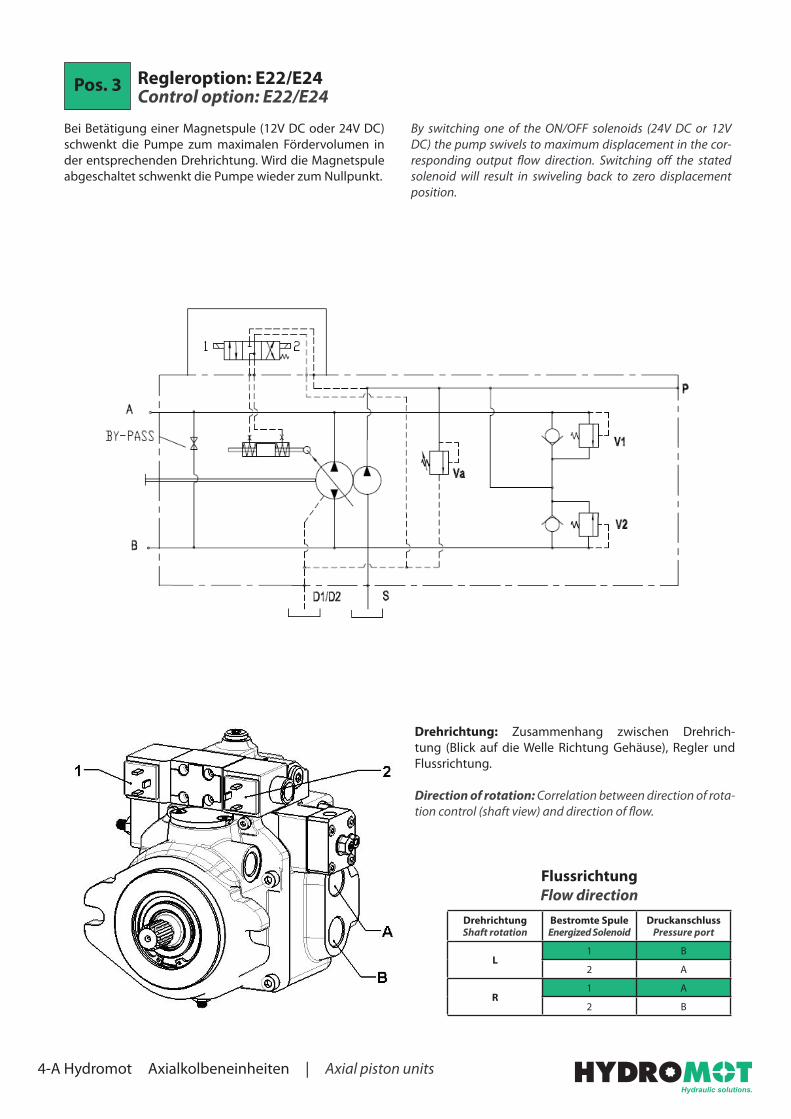
Pos. 3 Regleroption: E22/E24 Control option: E22/E24
By switching one of the ON/OFF solenoids (24V DC or 12V DC) the pump swivels to maximum displacement in the cor-responding output flow direction. Switching off the stated solenoid will result in swiveling back to zero displacement position.
Bei Betätigung einer Magnetspule (12V DC oder 24V DC)schwenkt die Pumpe zum maximalen Fördervolumen in der entsprechenden Drehrichtung. Wird die Magnetspule abgeschaltet schwenkt die Pumpe wieder zum Nullpunkt.
DrehrichtungShaft rotation
Bestromte SpuleEnergized Solenoid
DruckanschlussPressure port
L1 B
2 A
R1 A
2 B
Flussrichtung Flow direction
Drehrichtung: Zusammenhang zwischen Drehrich-tung (Blick auf die Welle Richtung Gehäuse), Regler und Flussrichtung.
Direction of rotation: Correlation between direction of rota-tion control (shaft view) and direction of flow.

4-A Hydromot Axialkolbeneinheiten | Axial piston units
Einbaumaße mm [in.]Dimensions mm [in.]
mm [in]A / B Druckanschluss
Pressure port
D1 / D2 LeckölanschlussDrain port
S SauganschlussSuction port
P SpeisedruckanschlussPressure port
VA SpeisepumpenventilCharge pump valve
V1 / V2 Max. Druck VentilMax. pressure valve
SL HubbegrenzungStroke limiter
ZM Schraube NullpunkteinstellungMechanical zero adjustment screw
a / b SteuerdruckanschlussControl piloting pressure port
p1 DruckanschlussPressure port
BP BypassBypass
Pos. 8 Anschlüsse Ports
Option G Option U
A / B G 3/4“ 1 1/16-12 UNF
D1 / D2 G 1/2“ 3/4-16 UNF
S G 3/4“ 1 1/16-12 UNF
P G 1/8“G 1/4“
3/8-24 UNF7/16-20 UNF
a / b G 1/4“ 7/16-20 UNF
p1 G 1/4“ 7/16-20 UNF

4-A Hydromot Axialkolbeneinheiten | Axial piston units
Pos. 3 Regleroption: ER2/ER4 Control option: ER2/ER4
The pump displacement is directly proportional to the input current of one of the two proportional solenoids. Flow direc-tion depends on which solenoid is energized. Standard sole-noids are ON/OFF 24V DC (min. 210 mA / max. 800 mA) or 12V DC (min. 470 mA / max. 1500 mA).
Das Fördervolumen der Pumpe ist proportional zur Strom-stärke mit der eine der beiden Magnetspulen bestromt wird. Die Drehrichtung ist davon abhängig welche Spule betätigt wird. Standard Magnetspulen sind 24V DC (min. 210 mA / max. 800 mA) oder 12V DC (min. 470 mA / max. 1500 mA).
1600
14001200
1000800
600400
2000
-200-400
-600-800
-1000-1200-1400
-1600
Stro
mst
ärke
Cur
rent
[mA
]
Vg/Vg max%
-100 -50 0 50 100
DrehrichtungShaft rotation
SteuerdruckPiloting pressure
DruckanschlussPressure port
L1 B
2 A
R1 A
2 B
Flussrichtung Flow direction
12V
12V
24V
24V
Drehrichtung: Zusammenhang zwischen Drehrich-tung (Blick auf die Welle Richtung Gehäuse), Regler und Flussrichtung.
Direction of rotation: Correlation between direction of rota-tion control (shaft view) and direction of flow.

4-A Hydromot Axialkolbeneinheiten | Axial piston units
Einbaumaße mm [in.]Dimensions mm [in.]
mm [in]
Pos. 8 Anschlüsse Ports
Option G Option U
A / B G 3/4“ 1 1/16-12 UNF
D1 / D2 G 1/2“ 3/4-16 UNF
S G 3/4“ 1 1/16-12 UNF
P G 1/8“G 1/4“
3/8-24 UNF7/16-20 UNF
a / b G 1/4“ 7/16-20 UNF
A / B DruckanschlussPressure port
D1 / D2 LeckölanschlussDrain port
S SauganschlussSuction port
P SpeisedruckanschlussPressure port
VA SpeisepumpenventilCharge pump valve
V1 / V2 Max. Druck VentilMax. pressure valve
SL HubbegrenzungStroke limiter
ZM Schraube NullpunkteinstellungMechanical zero adjustment screw
a / b SteuerdruckanschlussControl piloting pressure port
BP BypassBypass

4-A Hydromot Axialkolbeneinheiten | Axial piston units
Pos. 3 Regleroption: EP2/EP4 Control option: EP2/EP4
The pump displacement is directly proportional to the input current of one of the two proportional solenoids. Flow is also influenced by working pressure. With a given input signal (piloting current) the pump can slightly vary the displacement and the flow when working pressure increases. The input cur-rent of the two proportional solenoids must be controlled by an external amplifier card. Flow direction depends on which solenoid is energized. Standard solenoids are proportional 24V DC or 12V DC (use connector DT04-2P). For emergency operation it‘s possible to control solenoids by bypassing the amplifier.
Das Fördervolumen der Pumpe ist proportional zur Strom-stärke mit der eine der beiden Magnetspulen bestromt wird. Die Fördermenge wird auch durch den Arbeitsdruck beeinflusst. Durch ein Eingangssignal (Steuerstrom) kann die Pumpe stufenlos das Fördervolumen und die För-dermenge variieren wenn der Arbeitsdruck steigt. Der Eingangsstrom des Proportionalventils muss durch eine externe Verstärkerkarte kontrolliert werden. Die Drehrich-tung ist davon abhängig welche Spule betätigt wird. Stan-dard Proportionalmagnetspulen sind 24V DC (Verbinder DT04-2P verwenden) oder 12V DC. Für den Notfallbetrieb ist es möglich die Spulen durch Überbrücken des Verstär-kers zu steuern.
1600
14001200
1000800
600400
2000
-200-400
-600-800
-1000-1200-1400
-1600
Stro
mst
ärke
Cur
rent
[mA
]
Vg/Vg max%
-100 -50 0 50 100
DrehrichtungShaft rotation
SteuerdruckPiloting pressure
DruckanschlussPressure port
L1 A
2 B
R1 B
2 A
Flussrichtung Flow direction
Drehrichtung: Zusammenhang zwischen Drehrich-tung (Blick auf die Welle Richtung Gehäuse), Regler und Flussrichtung.
Direction of rotation: Correlation between direction of rota-tion control (shaft view) and direction of flow.

4-A Hydromot Axialkolbeneinheiten | Axial piston units
Einbaumaße mm [in.]Dimensions mm [in.]
mm [in]A / B Druckanschluss
Pressure port
D1 / D2 LeckölanschlussDrain port
S SauganschlussSuction port
P SpeisedruckanschlussPressure port
VA SpeisepumpenventilCharge pump valve
V1 / V2 Max. Druck VentilMax. pressure valve
SL HubbegrenzungStroke limiter
ZM Schraube NullpunkteinstellungMechanical zero adjustment screw
a / b SteuerdruckanschlussControl piloting pressure port
p1 DruckanschlussPressure port
BP BypassBypass
Pos. 8 Anschlüsse Ports
Option G Option U
A / B G 3/4“ 1 1/16-12 UNF
D1 / D2 G 1/2“ 3/4-16 UNF
S G 3/4“ 1 1/16-12 UNF
P G 1/8“G 1/4“
3/8-24 UNF7/16-20 UNF
a / b G 1/4“ 7/16-20 UNF
p1 G 1/4“ 7/16-20 UNF
4-A Hydromot Axialkolbeneinheiten | Axial piston units
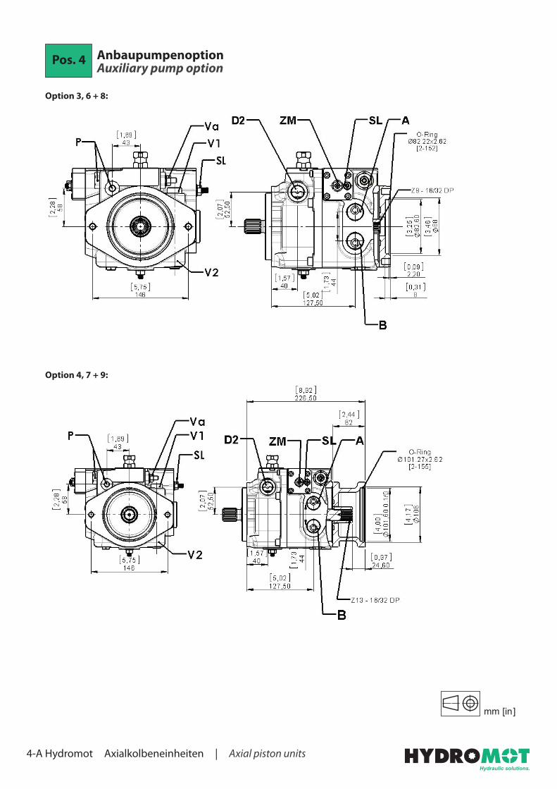
Pos. 4 Anbaupumpenoption Auxiliary pump option
Option 3, 6 + 8:
Option 4, 7 + 9:
mm [in]

4-A Hydromot Axialkolbeneinheiten | Axial piston units
Option 10:
mm [in]
Pos. 7 Antriebswelle / Durchtriebswelle Driveshaft / Through drive shaft
Antriebswelle Driveshaft
Option 1 + 4: Option 2, 3 + 5: Option 6:
mm [in]

4-A Hydromot Axialkolbeneinheiten | Axial piston units
Durchtriebswelle Through drive shaft
Option 4: Option 5: Option 3:
Pos. 9 Zusätzliche Optionen Additional optionsPos. 10+
Option BP: Bypass
The bypass valve is a tap inside the pump which allows, if necessary, a connection between pressure line A and B.
Das Bypass Ventil ist eine Verschlussschraube im Inneren der Pumpe, die wenn nötig, eine Verbindung zwischen den Druckleitungen A und B schafft.
mm [in]

4-A Hydromot Axialkolbeneinheiten | Axial piston units
Option FI: Filter
In order to guarantee an optimum stability of the fluid conta-mination conditions the pump could be equipped with a filter positioned on the delivery outlet of the booster pump. Only the flow necessary to reintegrate the lost oil due to drainage will pass through this filter. The excess flow, which is drained by the booster pump valve, is not filtered. In this way a longer filter life would be realised.
Um ein optimales Level der Ölreinheit zu gewährleisten, kann die Pumpe mit einem Filter ausgestattet werden. Der Filter wird am Ausgang der Speisepumpe positioniert. Nur das benötigte Öl um den Kreislauf wieder zu füllen passiert diesen Filter. Das überschüssige Öl, das vom Ventil der Spei-sepumpe abgespritzt wird, wird nicht gefiltert. Dadurch wird eine längere Lebensdauer des Filters realisiert.
Einbaumaße mm [in.]Dimensions mm [in.]
mm [in]

4-A Hydromot Axialkolbeneinheiten | Axial piston units
Option FE: Filter mit elektrischem SensorOption FE: Filter with electric sensor
Upon request it‘s possible to add an electrical filter clogging sensor (Connector DIN 43650A) to the filter.
Es ist möglich den Filter zusätzlich mit einer elektrischen Verschmutzungsanzeige zu erhalten (Stecker DIN 43650A).
no
ncSpannung
VoltageMax. ohmsche Belastung
Max. resistive loadMax. induktive Belastung
Max. inductive load
125 - 250V AC 1 A 1 A
30V DC 2 A 2 A
50V DC 0,5 A 0,5 A
75V DC 0,25 A 0,25 A
125V DC 0,2 A 0,03 A
Einbaumaße mm [in.]Dimensions mm [in.]
mm [in]

4-A Hydromot Axialkolbeneinheiten | Axial piston units
Option P1 + P2: Absperrventil elektrisch 12V (P1) oder 24V (P2)Option P1 + P2: Electric Cut-Off valve 12V (P1) or 24V (P2)
The electric Cut-Off valve brings the displacement of the pump to zero when power supply of the ON/OFF solenoid is cut-off.Feed voltage is 12V DC or 24V DC. Cut-Off valve isn‘t available for Tandempump - Short version.
Wenn die Spannung der Magnetspule abgeschaltet wird schwenkt die Pumpe in Nullstellung und fördert nicht mehr.Spannungsversorgung ist 12V DC oder 24V DC. Das Absperrventil ist nicht für Doppelpumpen - Kurzversion erhältlich.
Einbaumaße mm [in.]Dimensions mm [in.]
mm [in]

4-A Hydromot Axialkolbeneinheiten | Axial piston units
Option VS: SpülventilOption VS: Flushing valve
The flushing valve allows an oil cooling action. This is recom-mended when operating at high speed and power.
Das Spülventil kühlt das Öl. Dies wird nötig wenn die Pumpe bei hohen Drehzahlen und Kräften betrieben wird.
Einbaumaße mm [in.]Dimensions mm [in.]
mm [in]
4-A Hydromot Axialkolbeneinheiten | Axial piston units
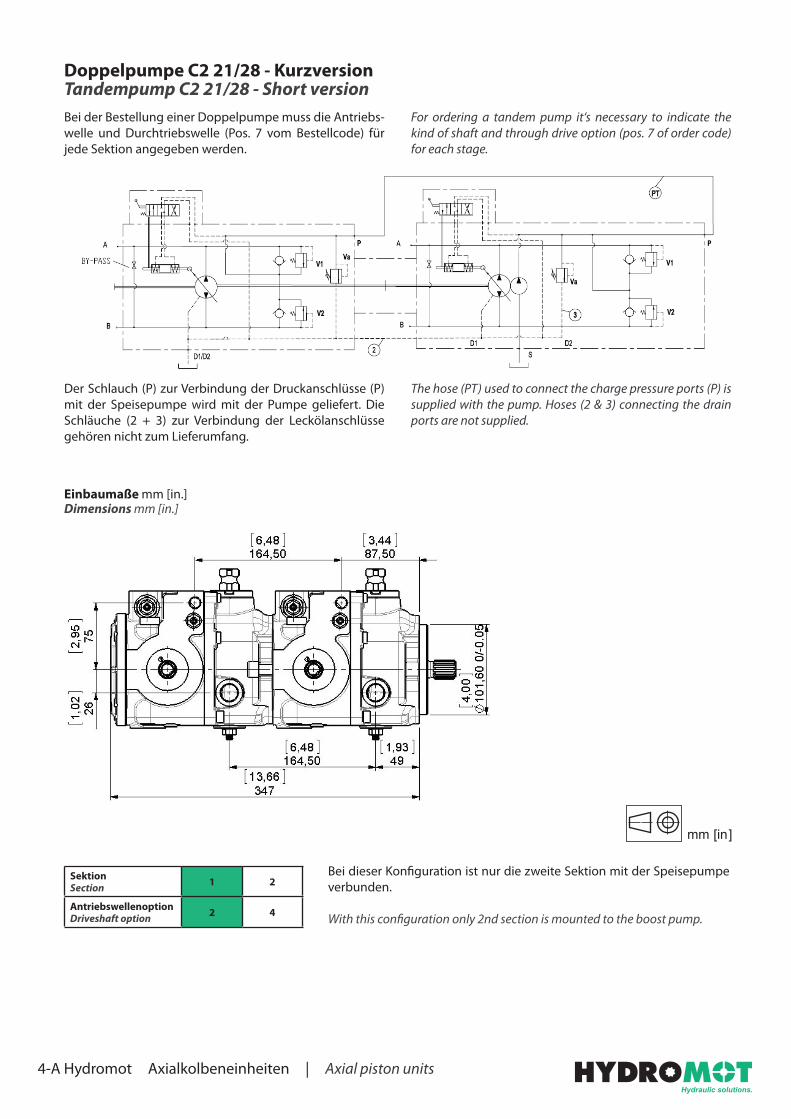
Doppelpumpe C2 21/28 - Kurzversion Tandempump C2 21/28 - Short version
For ordering a tandem pump it‘s necessary to indicate the kind of shaft and through drive option (pos. 7 of order code) for each stage.
Bei der Bestellung einer Doppelpumpe muss die Antriebs-welle und Durchtriebswelle (Pos. 7 vom Bestellcode) für jede Sektion angegeben werden.
The hose (PT) used to connect the charge pressure ports (P) is supplied with the pump. Hoses (2 & 3) connecting the drain ports are not supplied.
Der Schlauch (P) zur Verbindung der Druckanschlüsse (P) mit der Speisepumpe wird mit der Pumpe geliefert. Die Schläuche (2 + 3) zur Verbindung der Leckölanschlüsse gehören nicht zum Lieferumfang.
SektionSection 1 2
AntriebswellenoptionDriveshaft option 2 4
Einbaumaße mm [in.]Dimensions mm [in.]
mm [in]
Bei dieser Konfiguration ist nur die zweite Sektion mit der Speisepumpe verbunden.
With this configuration only 2nd section is mounted to the boost pump.

4-A Hydromot Axialkolbeneinheiten | Axial piston units
Doppelpumpe C2 21/28 - Langversion Tandempump C2 21/28 - Long version
SektionSection 1 2
AntriebswellenoptionDriveshaft option 3 1
Doppelpumpe C2 21/28 + C2 21/28 SAE-B - Einbaumaße mm [in.]Tandempump C2 21/28 + C2 21/28 SAE B - Dimensions mm [in.]
mm [in]
Bei dieser Konfiguration sind beide Sektionen mit der Speisepumpe verbunden.
With this configuration both sections are mounted to the boost pump.
SektionSection 1 2
AntriebswellenoptionDriveshaft option 1 1 oder or 2
mm [in]
Bei dieser Konfiguration sind beide Sektionen mit der Speisepumpe verbunden.
With this configuration both sections are mounted to the boost pump.
Doppelpumpe C2 21/28 + C1 14/18 - Einbaumaße mm [in.]Tandempump C2 21/28 + C1 14/18 - Dimensions mm [in.]