allen-bradley - plccenter.cn · publication 1771-6.5.120 — march 1998 this manual shows you how...
TRANSCRIPT

User ManualTemperature Control Module
(Cat. No. 1771-TCM Series C)(Cat. No. 1771-TCMR Series A)
Allen-Bradley

Because of the variety of uses for the products described in thispublication, those responsible for the application and use of this controlequipment must satisfy themselves that all necessary steps have beentaken to assure that each application and use meets all performance andsafety requirements, including any applicable laws, regulations, codesand standards.
The illustrations, charts, sample programs and layout examples shown inthis guide are intended solely for purposes of example. Since there aremany variables and requirements associated with any particularinstallation, Allen-Bradley does not assume responsibility or liability (toinclude intellectual property liability) for actual use based upon theexamples shown in this publication.
Allen-Bradley publication SGI-1.1, Safety Guidelines for theApplication, Installation, and Maintenance of Solid-State Control(available from your local Allen-Bradley office), describes someimportant differences between solid-state equipment andelectromechanical devices that should be taken into consideration whenapplying products such as those described in this publication.
Reproduction of the contents of this copyrighted publication, in whole orin part, without written permission of Allen-Bradley Company, Inc., isprohibited.
Throughout this manual we use notes to make you aware of safetyconsiderations:
!ATTENTION: Identifies information about practices orcircumstances that can lead to personal injury or death,property damage or economic loss.
Attention statements help you to:
• identify a hazard
• avoid the hazard
• recognize the consequences
Important: Identifies information that is critical for successfulapplication and understanding of the product.
PLC, PLC-2, PLC-3, PLC-5 are registered trademarks of Allen-Bradley Company, Inc.
PanelView, Pro-Set, ControlView and RSView are trademarks of Rockwell Automation, Inc.
Important User Information

Publication 1771-6.5.120 — March 1998
This manual now covers two temperature control modules that arenearly identical, except for the type of temperature sensor:
• 1771-TCM (firmware revision 3.3) for thermocouples
• 1771-TCMR (new release) for resistance type sensors
We made these changes to this manual:
• Added a lowpass filter to the temperature input– enabled (1) disabled (0) by Configuration Block word 2, bit 13– time constant (0–9.9 sec) stored in Configuration word 25
• To accelerate reaching the initial setpoint, added an auto-tunestartup aggressiveness parameter stored in Configuration word 14.
• Added a setpoint ramp-hold bit for use when ramping to a setpoint. – enabled (1) holds the setpoint at the current value– disabled (0) restores ramping to the selected setpointEnabled in the Dynamic block for each loop.
• Added a selectable display mode that displays temperature in 1o
increments and creates a 1o deadband at the setpoint.
Enabled in the Dynamic block for all loops or none.
• Added a status bit to indicate the direction of ramping for each loop.Indicated in the System Status block for each loop.
• Changed the initialization rung of the communication program:– to clear the TPO bits (for block and single transfer)– to write valid Configuration and Auto-tune Blocks to the module– to avoid clearing the gains block on first scan
We improved module performance with these firmware adjustments:
• After auto-tune, errors are reported as warnings rather than faults.
• The anti-repeat windup (integral action) is faster and more active.
• When downloading an auto-tune or gains block to the modulecontrolling in automatic mode, the integral sum is scaled by theratio of old-to-new gains to minimize the bump.
• The Heat PID gains generated by auto-tune have been moderatedfor more stable control.
• Heat/Cool now uses split-range control with the same I term for bothto provide smoother transitions between heating and cooling.
Important: If replacing an earlier module in heat/cool mode, youmust auto tune the module to establish valid PID values.
Modules Covered by this Manual
Summary of Changesfor 1771-TCM FirmwareRevision 3.3

SOC–ii
Publication 1771-6.5.120 — March 1998
Important: Either module now includes configuration software withaccompanying manual (publication 1771-6.4.5) and a communicationladder program. They simplify the procedures to configure and programthe module. We describe the communication program in appendix C.
Important: The communication program and configuration softwareare also available from the Internet. Access them from our website: www.ab.com/plclogic/prodinfo/io/I_O/tcmsw/index.html
You must have INTERCHANGE software to use the configurationsoftware. You must have a programming software to download thecommunication program to your PLC processor.
Standardized Terminology (throughout manual)
Our terminology is generally consistent with customer usage, butinconsistent with ISA/IEEE. This table should clarify some definitions.
Existing A-B Term: ISA/IEEE Term: Meaning:
Control Variable (V or CV)Controller Output (CO)
Manipulated Variable (M)what the controller applies to thecontrol system
Process Variable (PV) Controlled Variable (C)in a control loop, that which is directlymeasured or controlled
n/a Process Variable (PV)any variable of the process, includingthe manipulated variable and thecontrolled variable
Proportional Gain (Kp) Controller Gain (Kc)Overall gain for the loop withdependent PID action (affectsintegral and derivative terms as well)
We also changed the term “system” status to “module” statusbecause that is what the module returns to the processor.
This module can use any of these resistance-type sensors:
• 100 ohm platinum (USA)
• 100 ohm platinum (Euro)
• 120 ohm nickel
• 10 ohm copper
Input connections to the module are routed through the 1771-RTP4remote termination panel. Installation, programming, powerrequirements, and module specifications are otherwise identical to the 1771-TCM module.
About the 1771-TCMR Module

Publication 1771-6.5.120 — March 1998
This manual shows you how to use your Temperature Control Modulein an Allen-Bradley PLC system for barrel temperature control andother injection molding or extrusion-related temperature controlapplications. The modules covered in this manual are:
• cat. no. 1771-TCM, Series C or Series B with firmware release 3.3
• cat. no. 1771-TCMR, Series A, for resistance-type sensors
This manual helps you install, program, calibrate, and troubleshootyour TCM or TCMR module. TemperatureControl configurationsoftware is included with either module. For information on usingTemperatureControl configuration software, see manual 1771-6.4.5.
You must be able to program and operate Allen-Bradley programmablecontrollers to make efficient use of these modules. In particular, youmust know how to program block-transfers. If not, refer to applicablePLC programming manuals before attempting to write programs.
In this manual, we refer to the:
• temperature control module as the “module”Where there are differences, we designate TCM or TCMR
• programmable controller, as the “PLC processor” or the “processor”
• thermocouple as a “TC”
• resistance–type sensor as a resistance temperature device “RTD”
• time-proportioned output as “TPO”
• tuning-assisted process as “TAP”
• proportional-integral-derivative terms as “PID” terms
For a list of publications with information on Allen-Bradleyprogrammable controller products, consult publication index SD499.
If you are going to use: Refer to:
TemperatureControl Configuration Software
• Temperature Control Module Programming Manual(publication 1771-6.4.5)
Pro-Set 700 Software• Pro-Set 700 Reference Manual (publication 6500-6.4.3)• Pro-Set 700 User Manual (publication 6500-6.5.18)• Pro-Set 700 Systems Job-Setting Guide (publication 6500-6.9.3)
PanelView, RSView or other man-machine interface
• PanelBuilder 900 Configuration Software (publication 2711-815)• other publications that accompanied the product
Audience
Terminology
Related Publications

Using This ManualP–2
Publication 1771-6.5.120 — March 1998
Notes:

Table of Contents i
Overview of TCM and TCMR Temperature Control Modules Chapter 1
Module Features 1–1. . . . . . . . . . . . . . . . . . . . . . . . . . . . . . . . . . . . Temperature Control in a PLC System 1–2. . . . . . . . . . . . . . . . . . . . . How the Module Communicates with the PLC Processor 1–3. . . . . . . Restriction of Use in a Remote I/O Chassis 1–4. . . . . . . . . . . . . . . . .
Use of Data Table 1–5. . . . . . . . . . . . . . . . . . . . . . . . . . . . . . . . Processor Compatibility 1–5. . . . . . . . . . . . . . . . . . . . . . . . . . . .
Compatible Replacement for Series B TCM Modules 1–5. . . . . . . . . . Standard Terminology 1–6. . . . . . . . . . . . . . . . . . . . . . . . . . . . . . . .
Installing the Module Chapter 2Compliance with European Union Directives 2–1. . . . . . . . . . . . . . . .
EMC Directive 2–1. . . . . . . . . . . . . . . . . . . . . . . . . . . . . . . . . . Low Voltage Directive 2–2. . . . . . . . . . . . . . . . . . . . . . . . . . . . .
Protecting from Electrostatic Damage 2–2. . . . . . . . . . . . . . . . . . . . . 1. Calculating Backplane Current Load 2–2. . . . . . . . . . . . . . . . . . . . 2. Determining I/O Chassis Addressing Mode 2–2. . . . . . . . . . . . . . . 3. Determining Module Location in the I/O Chassis 2–3. . . . . . . . . . . . 4. Keying the I/O Chassis Slot for the Module 2–3. . . . . . . . . . . . . . . . 5. Planning for Sufficient Depth of I/O Enclosure 2–4. . . . . . . . . . . . . . 6. Installing the Remote Termination Panel 2–4. . . . . . . . . . . . . . . . . . 7. Installing the Cables 2–5. . . . . . . . . . . . . . . . . . . . . . . . . . . . . . . . 8. Connecting Inputs to the Remote Termination Panel 2–6. . . . . . . . .
Thermocouple (TC) Connections 2–7. . . . . . . . . . . . . . . . . . . . . Resistance-bulb (RTD) Connections 2–7. . . . . . . . . . . . . . . . . . .
9. Grounding the Shields 2–7. . . . . . . . . . . . . . . . . . . . . . . . . . . . . . 10. Observing Installion Precautions 2–8. . . . . . . . . . . . . . . . . . . . . . 11. Interpreting Indicator Lights 2–8. . . . . . . . . . . . . . . . . . . . . . . . . .
Module Communication Chapter 3I/O Image 3–1. . . . . . . . . . . . . . . . . . . . . . . . . . . . . . . . . . . . . . . . . Single-Transfer Programming 3–1. . . . . . . . . . . . . . . . . . . . . . . . . . .
Control Bits 3–2. . . . . . . . . . . . . . . . . . . . . . . . . . . . . . . . . . . . . TPO Bits 3–3. . . . . . . . . . . . . . . . . . . . . . . . . . . . . . . . . . . . . . Controlling Heating Elements Only 3–4. . . . . . . . . . . . . . . . . . . . Controlling Heating and Cooling Elements 3–5. . . . . . . . . . . . . . .
Communication Sequence 3–7. . . . . . . . . . . . . . . . . . . . . . . . . . . . . Block-Transfer Programming 3–9. . . . . . . . . . . . . . . . . . . . . . . . . . .
Block-Transfer Write 3–10. . . . . . . . . . . . . . . . . . . . . . . . . . . . . Block-Transfer Read 3–11. . . . . . . . . . . . . . . . . . . . . . . . . . . . .
Module Update Period 3–11. . . . . . . . . . . . . . . . . . . . . . . . . . . . . . .

ii Table of Contents
Configuring the Module Chapter 4Block Identification 4–1. . . . . . . . . . . . . . . . . . . . . . . . . . . . . . . . . . . Open-Circuit Detection 4–1. . . . . . . . . . . . . . . . . . . . . . . . . . . . . . . . Barrel/Non-Barrel Control 4–2. . . . . . . . . . . . . . . . . . . . . . . . . . . . . .
Switch to Barrel Control? 4–2. . . . . . . . . . . . . . . . . . . . . . . . . . . Inner/Outer Zone 4–3. . . . . . . . . . . . . . . . . . . . . . . . . . . . . . . . . . . . Thermal Integrity Loss Detection (formerly called thermal runaway) 4–3Alarms 4–4. . . . . . . . . . . . . . . . . . . . . . . . . . . . . . . . . . . . . . . . . . . Alarm Dead Band 4–4. . . . . . . . . . . . . . . . . . . . . . . . . . . . . . . . . . . Loop Operational Mode 4–5. . . . . . . . . . . . . . . . . . . . . . . . . . . . . . . Inferred Decimal Point 4–5. . . . . . . . . . . . . . . . . . . . . . . . . . . . . . . . Configuration Block 4–6. . . . . . . . . . . . . . . . . . . . . . . . . . . . . . . . . .
Saving/Restoring Auto-Tuning Parameters Chapter 5
Sequence of Block-Transfers 5–1. . . . . . . . . . . . . . . . . . . . . . . . . . . Block Identification 5–1. . . . . . . . . . . . . . . . . . . . . . . . . . . . . . . . . . . Inferred Decimal Point 5–1. . . . . . . . . . . . . . . . . . . . . . . . . . . . . . . . Auto-Tune Block 5–2. . . . . . . . . . . . . . . . . . . . . . . . . . . . . . . . . . . .
Setting Proportional-Integral-Derivative Gains Chapter 6
Sequence of Block-Transfers 6–1. . . . . . . . . . . . . . . . . . . . . . . . . . . Fine-Tuning the Loops 6–2. . . . . . . . . . . . . . . . . . . . . . . . . . . . . . . . The PID Equation 6–2. . . . . . . . . . . . . . . . . . . . . . . . . . . . . . . . . . . Block Identification 6–3. . . . . . . . . . . . . . . . . . . . . . . . . . . . . . . . . . . Inferred Decimal Point 6–3. . . . . . . . . . . . . . . . . . . . . . . . . . . . . . . . Gains Block 6–3. . . . . . . . . . . . . . . . . . . . . . . . . . . . . . . . . . . . . . . .
Operating the Module (Dynamic Block) Chapter 7
Sequence of Block-Transfers 7–1. . . . . . . . . . . . . . . . . . . . . . . . . . . Block Identification 7–1. . . . . . . . . . . . . . . . . . . . . . . . . . . . . . . . . . . Control Mode Selection 7–1. . . . . . . . . . . . . . . . . . . . . . . . . . . . . . . Inferred Decimal Point 7–2. . . . . . . . . . . . . . . . . . . . . . . . . . . . . . . . Dynamic Block 7–2. . . . . . . . . . . . . . . . . . . . . . . . . . . . . . . . . . . . .
Monitoring Status Data Chapter 8Sequence of Block-Transfers 8–1. . . . . . . . . . . . . . . . . . . . . . . . . . . Block Identification 8–1. . . . . . . . . . . . . . . . . . . . . . . . . . . . . . . . . . . Implied Decimal Point 8–1. . . . . . . . . . . . . . . . . . . . . . . . . . . . . . . . Module Status Block 8–1. . . . . . . . . . . . . . . . . . . . . . . . . . . . . . . . . Alarms Returned in the Module Status Block 8–2. . . . . . . . . . . . . . . .

Table of Contents iii
Calibrating the Module Chapter 9Tools and Equipment 9–1. . . . . . . . . . . . . . . . . . . . . . . . . . . . . . . . . When to Calibrate 9–1. . . . . . . . . . . . . . . . . . . . . . . . . . . . . . . . . . . Indicator Operation During Calibration 9–1. . . . . . . . . . . . . . . . . . . . . Preparing to Calibrate 9–1. . . . . . . . . . . . . . . . . . . . . . . . . . . . . . . . Calibration Write Block 9–2. . . . . . . . . . . . . . . . . . . . . . . . . . . . . . . . Calibration Read Block 9–2. . . . . . . . . . . . . . . . . . . . . . . . . . . . . . . . Calibration Procedure 9–3. . . . . . . . . . . . . . . . . . . . . . . . . . . . . . . .
Troubleshooting Chapter 10Diagnostics Reported through the Indicators 10–1. . . . . . . . . . . . . . . . Troubleshooting with Indicators 10–1. . . . . . . . . . . . . . . . . . . . . . . . . . Locating Errors with the Status Block 10–2. . . . . . . . . . . . . . . . . . . . . .
Pointer for Errors in the Configuration and Gains Blocks 10–2. . . . . Pointer for Dynamic-Block Errors and Auto-Tuning Alarms 10–3. .
Specifications Appendix A
Default Parameter Values Appendix B
Example Ladder Program Appendix CThe Ladder Program C–1. . . . . . . . . . . . . . . . . . . . . . . . . . . . . . . . . Program File C–1. . . . . . . . . . . . . . . . . . . . . . . . . . . . . . . . . . . . . . . Data-Table Files C–1. . . . . . . . . . . . . . . . . . . . . . . . . . . . . . . . . . . .
Data-Table Files O and I C–2. . . . . . . . . . . . . . . . . . . . . . . . . . . Data-Table File 7 (N) Integer C–3. . . . . . . . . . . . . . . . . . . . . . . . Data-Table File 9 (BT) Block Transfer C–3. . . . . . . . . . . . . . . . . .
Data-Table Interface Layout C–3. . . . . . . . . . . . . . . . . . . . . . . . . . . . Communication Control Bits C–4. . . . . . . . . . . . . . . . . . . . . . . . . Single-Transferred TPO Bits C–4. . . . . . . . . . . . . . . . . . . . . . . . Block-Transferred TPO Bits C–5. . . . . . . . . . . . . . . . . . . . . . . . . Temperature Monitor Words C–6. . . . . . . . . . . . . . . . . . . . . . . . . Loop Output Words C–6. . . . . . . . . . . . . . . . . . . . . . . . . . . . . . . Current Setpoint Words C–6. . . . . . . . . . . . . . . . . . . . . . . . . . . .
Establish the Module Interface for Your Application C–7. . . . . . . . . . . . Configure the Control Loops C–7. . . . . . . . . . . . . . . . . . . . . . . . . . . . Start Up and Auto-Tune Loops Set for Barrel Control C–8. . . . . . . . . . Basic Operation of the Communication Program C–8. . . . . . . . . . . . . Rung 2:0 Initialization C–10. . . . . . . . . . . . . . . . . . . . . . . . . . . . . . . . . Rung 2:1 and 2:2 250ms Time Base for Automatic Block-Transfer C–11. Rung 2:3 Manual Block-Transfer Request, Identification, and Control C–12Rung 2:4 Loop Configuration/Gain Data Download Control Support C–14Rung 2:5 Automatic Dynamic-Block-Transfer Writes C–14. . . . . . . . . . Rung 2:6 Manual-Request Block- Transfer Write Control C–15. . . . . . . Rung 2:7 Block-Transfer Read Control C–15. . . . . . . . . . . . . . . . . . . . Rung 2:8 Block-Transfer Read Data Distribution C–16. . . . . . . . . . . . . Rungs 2:9 thru 2:13 Single-Transfer TPO Interface C–16. . . . . . . . . . .

iv Table of Contents
Auto-tuning Appendix DAuto-tuning the Loops D–1. . . . . . . . . . . . . . . . . . . . . . . . . . . . . . . . Module Function D–2. . . . . . . . . . . . . . . . . . . . . . . . . . . . . . . . . . . .
Using Pro-Set 700 Software Appendix EConfiguring and Setting Up Loops E–1. . . . . . . . . . . . . . . . . . . . . . . . Loop Start-Up and Tuning E–4. . . . . . . . . . . . . . . . . . . . . . . . . . . . . . Considerations for Pro-Set 700 Release 2.0 Software E–6. . . . . . . . . .

Publication 1771-6.5.120 — March 1998
This chapter gives you information on:
• module features
• temperature control in a PLC system
• how the module communicates with the PLC processor
• restriction of use in an I/O chassis
• compatible replacement of a series B TCM module
• standard terminology
TCM or TCMR modules provide:
• 8 independent heat/cool temperature control loops
• auto-tuning of PID loops (one loop or any combination of loopscan be auto-tuned while other loops are running) and a uniquestart-up algorithm
• for TCM modules, an isolated TC input (types B, E, J, K, R, S, T)or (+100mV) for each PID loop
• for TCMR modules, a 100 ohm platinum, 120 ohm nickel, or 10ohm copper resistance-type (RTD) sensor for each PID loop
• 16-bit analog-to-digital converter resolution (0.1° resolution)
• heat signal (PID loop output) to the data table as a numeric %value for each temperature loop
• cool signal (PID loop output) to the data table as a numeric %value for each temperature loop
• a heat signal (for each PID loop) to the data table as a TPO bit
• a cool signal (for each PID loop) to the data table as a TPO bit
• temperature values in °C or °F• self-calibration (external reference required)
• user-selectable high and low alarms with dead band for hysteresis
• input open-circuit detection
Module Features

1–2 Overview of TCM and TCMR Temperature Control Modules
Publication 1771-6.5.120 — March 1998
The TCM and TCMR modules are intelligent I/O modules that providea maximum of 8 PID loops for temperature control. Either module has8 analog inputs: the TCM module is designed for thermocouple (TC)inputs, the TCMR module is designed for resistance type device(RTD) inputs. The module performs the PID algorithm and tuning-assisted-process (TAP) algorithm for each loop. The output of eachloop is sent from the module to the PLC data table. Your applicationladder logic must access the loop output in the data table and send it toan output module to close the loop.
TCM or TCMR Module
PLC Data Table Output ModuleAnalog (numeric) or Digital (TPO)
Heater
TC or RTD
Process to be
ControlledLoop Logic
output
Loop Logic
Loop Logic
Loop Logic
Loop Logic
Loop Logic
Loop Logic
Loop Logic
output
output output
input 1
2
3
4
5
6
7
8
The output of each loop is sent from the module to the PLC data tableas both an analog (numeric) value and as the duty cycle of a bit that iscycled at a regular period. We call this duty-cycle bit a time-proportioned output (TPO) bit.
Your ladder logic can monitor the analog (numeric) value and send itto an analog output module to generate the output signal to an analogtemperature control actuator. Or, your ladder logic can send the TPOsignal to a digital output module to generate the TPO output signal toan on/off temperature control actuator.
X
Y
On
Off
Duty Cycle = —XY
TPO Bit
X = On TimeY = TPO Period
Temperature Control in aPLC System

1–3Overview of TCM and TCMR Temperature Control Modules
Publication 1771-6.5.120 — March 1998
TCM and TCMR modules communicate with the PLC processor byboth block-transfer and single-transfer. Your application ladder logicmust include block-transfer write instructions to send the followingdata blocks to the module:
• a configuration block for each (8 max) PID loop (chapter 4)
• auto-tune block (chapter 5)
• gains block (chapter 6)
• dynamic block (chapter 7)
• calibration block (not required for normal operation)(chapter 9)
Your ladder logic must include block-transfer read instructions to getthe following data blocks from the module:
• auto-tune block (chapter 5)
• gains block (chapter 6)
• system status (chapter 8)
• calibration block (not required for normal operation)(chapter 9)
Unless the module is located in an I/O chassis (with a 1771-ASB I/Oadapter) on a universal remote I/O link providing heat/cool control,you can use the high-speed TPO signals by including instructions inthe ladder logic for examining an input image byte which is single-transferred from the module. This byte contains the output of eachloop as the duty cycle of a TPO bit that is cycled at a regular period.Each bit corresponds to one of the 8 PID loops.
Configuration Block for Loop 225 words
Configuration Block for Loop 125 words
Configuration Block for Loop 325 words
Configuration Block for Loop 425 words
Configuration Block for Loop 525 words
Configuration Block for Loop 625 words
Configuration Block for Loop 725 words
Configuration Block for Loop 825 words
Gains Block57 words
System Status Block64 words
Calibration Write Block20 words
Auto-Tune Block57 words
TCM or TCMR ModuleInput Byte
Block-Transfer
Block-Transfer
Block-Transfer
Block-Transfer
Block-Transfer
Block-Transfer
Block-Transfer
Block-Transfer
Block-Transfer
Block-Transfer
Block-Transfer
Block-Transfer
Calibration Read Block14 words
Block-Transfer
Output Byte
Dynamic Block34 words
Block-Transfer
Single-Transfer
Single-TransferPLC Data Table
How the ModuleCommunicates with thePLC Processor

1–4 Overview of TCM and TCMR Temperature Control Modules
Publication 1771-6.5.120 — March 1998
TCM and TCMR modules provide TPO signals thru both the block-transfer and single-transfer of I/O data. Single-transfer of TPO signalsprovide a faster output update to the temperature control actuator.
When a very fast cut-off is required in an operation controlling bothheat and cooling, place the module in a local chassis and use thesingle-transferred TPO signal. For heat-only or cool-only operation,the effective period for updating the single-transferred TPO bits isapproximately 10ms. If you alternately examine heat and cool TPObits, the effective period for updating the single-transferred TPO bits isapproximately 20ms.
However, do not use single-transferred TPO signals to control bothheating and cooling elements if the module is in an I/O chassis (with a1771-ASB adapter) on a universal remote I/O link. If multiplexedbetween heat and cool, this single-transfer TPO signal may beunreliable if the module is in an I/O chassis on a universal remote I/Olink. Therefore, this module can be used in a chassis on a remote I/Olink only in heat-only applications, cool-only applications, orapplications that don’t call for high-speed cut-off of the TPO signal.
!ATTENTION: The module can be used in an I/Ochassis (with 1771-ASB adapter) on a universal remoteI/O link only in applications that do NOT call for high-speed cut-off of TPO heat and cool signals. The moduleprovides TPO signals thru the block-transfer and single-transfer of I/O data. Single transfer provides fasterupdates of outputs to temperature control actuators.However, do not use single-transferred TPO signals tocontrol both heat and cool actuators if the module is in anI/O chassis (with 1771-ASB adapter) on a universalremote I/O link because under these conditions TPOsignals may be unreliable.
When using the module for heating/cooling in an I/O chassis on aremote I/O link, use the block-transferred TPO bits. These bits areupdated fast enough for most temperature control applications. Themodule’s period for updating the heat and cool bits it makes availablethru block-transfer is approximately 100ms.
Restriction of Use in aRemote I/O Chassis

1–5Overview of TCM and TCMR Temperature Control Modules
Publication 1771-6.5.120 — March 1998
Use of Data Table
Communication between module and processor is bi-directional. Themodule uses a byte in the output image table and a byte in the inputimage table for addressing block transfers. It also requires an area inthe data table to store the block-transfer read and write data. Theprocessor also single-transfers output data thru a second byte in theoutput image table to the module and single-transfers input data fromthe module thru a second byte in the input image table. These modulesuse 16 bits of I/O image table and require 1/2-slot or restricted 1-slotaddressing. Data table use and address restrictions are as follows:
Use of Data Table Compatibility
Catalog Number InputIm
OutputIm
Read-oc
Write-oc
Type of Addressingt o N mImageBits
ImageBits
BlockWords
BlockWords 1/2-slot 1-slot 2-slot
1771-TCM or -TCMR 16 16 192 342 max Yes R No
Yes = Compatible without restriction R = Restricted compatibility; it cannot be in the same even/odd pair of slots with a 32-bit moduleNo = Not compatible
You can place the module in any I/O slot of the I/O chassis. However,do not put the module into the same even/odd module-slot pair as a32-bit-density module unless you are using 1/2-slot addressing.
Processor Compatibility
If using TemperatureControl configuration software, you must use aPLC-5 processor. If not using configuration software, the module iscompatible with PLC-3 , PLC-5 , and PLC-5/250 processors. Themodule is not compatible with PLC-2 processors because theseprocessors cannot process integer values in natural binary format.
The TCM series C module is a compatible replacement for a series Bmodule. The only differences between them are:
• series C TCM module draws more backplane current from thepower supply (see chapter 2 and in appendix A)
• if the series C TCM module has a CE mark, it is approved forinstallation within the European Union and EEA regions. Theseries B module does not have the CE mark.
• series C TCM module (and series B updated to firmware release 3.3)expects two additional words in the configuration block to configurethe non-barrel auto-tune disturbance size.
Compatible Replacementfor Series B TCM Modules

1–6 Overview of TCM and TCMR Temperature Control Modules
Publication 1771-6.5.120 — March 1998
The avoid the confusion of referring to the same parameter with twodifferent terms (when comparing this manual with the ConfigurationSoftware manual, publication 1771-6.4.5) we have changed severalterms in this manual to comply with standard ISA/IEEE terminology:
Terms previously usedin this manual:
ISA/IEEE Terms nowused in this manual:
Meaning:
Control Variable (V or CV)Controller Output (CO)
Manipulated Variablewhat the controller applies to thecontrol system
Process Variable (PV) Controlled Variable (C)in a control loop, that which is directlymeasured or controlled
n/a Process Variable (PV)any variable of the process, includingthe manipulated variable and thecontrolled variable
Proportional Gain (Kp) Controller Gain (Kc)Overall gain for the loop withdependent PID action (affectsintegral and derivative terms as well)
Standard Terminology

Publication 1771-6.5.120 — March 1998
This chapter gives you information on:
• compliance with European Union directives
• protecting from electrostatic damage
It also gives you these installation steps:
1. calculating backplane current load
2. determining I/O chassis addressing mode
3. choosing module location in the I/O chassis
4. keying the I/O chassis slot for the module
5. planning for sufficient depth of I/O enclosure
6. installing the remote terminalion panel
7. installing the cables
8. connecting inputs to the remote termination panel
9. grounding the shields
10.observing installation precautions
11.interpreting indicator lights
If this product has the CE mark it is approved for installation withinthe European Union and EEA regions. It has been designed andtested to meet the following directives.
EMC Directive
This product is tested to meet Council Directive 89/336/EECElectromagnetic Compatibility (EMC) and the following standards,in whole or in part, documented in a technical construction file:
• EN 50081-2EMC – Generic Emission Standard, Part 2 – Industrial Environment
• EN 50082-2EMC – Generic Immunity Standard, Part 2 – Industrial Environment
This product is intended for use in an industrial environment.
Compliance with EuropeanUnion Directives

2–2 Installing the Module
Publication 1771-6.5.120 — March 1998
Low Voltage Directive
This product is tested to meet Council Directive 73/23/EECLow Voltage, by applying the safety requirements of EN 61131–2Programmable Controllers, Part 2 – Equipment Requirements and Tests.
For specific information required by EN 61131-2, see the appropriatesections in this publication, as well as these Allen-Bradley publications:
• Industrial Automation Wiring and Grounding Guidelines ForNoise Immunity, publication 1770-4.1
• Automation Systems Catalog
Electrostatic discharge can damage semiconductor devices inside thismodule if you touch backplane connector pins. Observing the following:
!ATTENTION: Electrostatic discharge can degradeperformance or cause permanent damage. Handle themodule as stated below.
• Wear an approved wrist-strap grounding device.
• Handle the module from the front, away from the backplane con-nector. Do not touch backplane connector pins.
• Keep the module in its static-shield box when not in use.
The module receives its power through the 1771 I/O chassis backplanefrom the chassis power supply. The maximum current loads are:
For This Module: The Max Load Current Is:
1771-TCM, series C steady state = 1.1A, surge = 1.5A
1771-TCMR steady state = 1.2A, surge = 1.5A
Add this load to the loads of all other modules in the I/O chassis. Thetotal load must not exceed the load specification for either the chassisbackplane or backplane power supply . For the 1771-P7 and -PS7power supplies, use the surge current rating. For other power supplies,use the steady state rating.
Because either module has a 16-I/O-bit density, you cannot use it inan I/O chassis set for 2-slot addressing. The module is compatiblewith either 1-slot or -slot addressing.
Protecting fromElectrostatic Damage
1. Calculating BackplaneCurrent Load
2. Determining I/O ChassisAddressing Mode

2–3Installing the Module
Publication 1771-6.5.120 — March 1998
The extreme left slot of an I/O chassis is not an I/O module slot; it isreserved for a processor or I/O adapter module.
• If you are using -slot addressing, you can place your moduleinto any I/O module slot of the I/O chassis.
• If you are using 1-slot addressing, do not place either module intothe same even/odd module-slot pair as a 32-bit-density module.The 32-bit module uses 2 bytes in the input image table and 2bytes in the output image table.
• Thermocouples provide very low-level analog signals. To mini-mize electrical noise interference, group analog and low-voltagedc digital modules away from ac modules or high voltage dc digi-tal modules.
• If your application requires high-speed cut-off of heat and coolTPO signal, do not install either module in an I/O chassis (with a1771-ASB I/O adapter) on a universal remote I/O link.
Use the plastic keying clips shipped with each I/O chassis, for keyingthe I/O slot to accept only this type of module.
!ATTENTION: Observe the following precautionswhen inserting or removing keying clips:
• insert or remove keying clips with your fingers• make sure that keying placement is correctIncorrect keying or the use of a tool can result indamage to the backplane connector and possiblesystem faults.
I/O modules are slotted in two places on the rear edge of the circuitboard. The position of the keys on the backplane connector mustcorrespond to these slots to allow insertion of the module. Place keyclips between these numbers labeled on the upper backplane connector.
UpperConnector
11022-I
ATTENTION: Insert or remove keying bands with your fingers.
I/O chassis
Keying Clips
Keying Positions
Between 26 and 28Between 32 and 34
You can change the position of these keys if subsequent system designand rewiring makes insertion of a different type of module necessary.
3. Determining ModuleLocation in the I/O Chassis
4. Keying the I/O ChassisSlot for the Module

2–4 Installing the Module
Publication 1771-6.5.120 — March 1998
Cable connectors extend beyond the front of the module. Your I/Oenclosure must provide room for a total of 215 mm (8.5 inches) fromthe backplane panel to the front of the cable connector installed onthe module.
The remote termination panel provides for input connections to themodule. You select the correct panel according to the type of input:
For this type of input: With this module: Use this panel:
thermocouple 1771-TCM 1771-RPT1*
resistance bulb 1771-TCMR 1771-RTP4
* contains cold-junction temperature compensation
Mount the panel in a location that provides a constant temperatureclose to ambient. Place the panel sufficiently close to the module sothe distance is within the length of the interconnect cable you choose.
• length of 1771-NC6 cable is 6 feet (1.8m)
• length of 1771-NC15 cable is 15 feet (4.6m)
To input devices
1771-RTP1 or -RPT4
1771-TCM or -TCMRModule
1771-NC6 or-NC15 Cables
The panels are designed for mounting on standard DIN 1 or DIN 3mounting rails. Mounting dimension are shown in the figure.
59 mm(2.3”)
135 mm(5.3”)
75 mm(3.0”)
1771-RTP1 or 1771-RTP4
J1J2J3J4
J8J7J6J5
AB
5. Planning for SufficientDepth of I/O Enclosure
6. Installing the RemoteTermination Panel

2–5Installing the Module
Publication 1771-6.5.120 — March 1998
Connect the 1771-NC6 or -NC15 cable to the module as shown:
1. Slide the locking bar up.
2. Insert the cable connector into the mating connector on module.
3. Lower the locking bar over the mating pins to lock the connector.
1. Raise locking bar. 2. Insert connector. 3. Lower locking bar to lock.
Locking bar
CableConnector
ModuleConnector
110234A
Connect the other end of each cable to the remote termination panel.
Important: You need two cables per module. Connect cable A fromthe top connecter to the right-hand connector on the panel. Connectcable B from the bottom connector on the left-hand connector on thepanel. Use thumb screws to lock the connectors to the panel.
RTP End of1771-NC cable
Module End of1771-NC cable
RTP1 or RPT4
DINRail
Connections for loops 5, 6, 7, 8,and cold-junction compensation
Connections for loops1, 2, 3, 4
Important: For thermocouple inputs: if using only 4 loops, use cable B(loops 5-8) because you must provide for cold-junction compensation.
7. Installing the Cables

2–6 Installing the Module
Publication 1771-6.5.120 — March 1998
The panel has a set of 4 screw terminals for each temperature controlloop input. With thermocouples, one terminal per loop is not used.
Cable Loop Terminal Label
Connect to: Cable Loop Terminal Label
Connect to:
I1 +Input 1 (+) I5 Input 5 (+)
1R1 –Return 1 (–)
5R5 Return 5 (–)
1S1 Shield 1 *
5S5 Shield 5 *
A O1 RTD single lead** B O5 RTD single lead**I2 Input 2 (+) I6 Input 6 (+)
2R2 Return 2 (–)
6R6 Return 6 (–)
2S2 Shield 2 *
6S6 Shield 6 *
O2 RTD single lead** O6 RTD single lead**I3 Input 3 (+) I7 Input 7 (+)R3 Return 3 (–)
7R7 Return 7 (–)
3S3 Shield 3 *
7S7 Shield 7 *
O3 RTD single lead** O7 RTD single lead**I4 Input 4 (+) I8 Input 8 (+)R4 Return 4 (–)
8R8 Return 8 (–)
4S4 Shield 4 *
8S8 Shield 8 *
O4 RTD single lead** O8 RTD single lead*** Ground each shield at one end, and only one end of the cable.** Not used for Thermocouples.
We show the terminal labels:
Remote TerminationPanel (RTP)
Loop 2
input
not used
shield
return
Loop 1
Label TC usage RTD usageIR
O
S shield
single lead
redundant leadredundant lead
To connect input wiring (22-12 AWG) to the panel:
1. Strip 9 mm (3/8 inch) of insulation from the wire.
2. Insert the wire into the open connector slot.
3. Tighten the screw to clamp the wire.
8. Connecting Inputs tothe Remote TerminationPanel

2–7Installing the Module
Publication 1771-6.5.120 — March 1998
Thermocouple (TC) Connections
W2 W3 R8 I8 R7 I7 R6 I6 R5 I5
CR CL S8 O8 S7 O7 S6 O6 S5 O5
SH
W1
R4 I4 R3 I3 R2 I2 R1 I1
S4 O4 S3 O3 S2 O2 S1 O1
S1 thru S8 are connectedinternally to SH.
Loop 8 Loop 1Loop 2Loop 3Loop 4Loop 5Loop 6Loop 7
Resistance-type Device (RTD) Connections
W2 W3 R8 I8 R7 I7 R6 I6 R5 I5
CR CL S8 O8 S7 O7 S6 O6 S5 O5
SH
W1
R4 I4 R3 I3 R2 I2 R1 I1
S4 O4 S3 O3 S2 O2 S1 O1
S1 thru S8 are connectedinternally to SH.
Loop 8 Loop 1Loop 2Loop 3Loop 4Loop 5Loop 6Loop 7
Refer to appendix D for additional information on input connections.
When using shielded cable or shielded thermocouple extension wire,ground the shield at only one end of the cable. We recommend thatyou connect the shield drain wire to the “S” connection on the panelfor each loop. All shield connections are connected together inside thepanel. You can ground the entire panel by connecting a single wirefrom the “SH” connection to the nearest ground bus.
If you do not want to ground a particular shield at the panel, you canremove the jumper for that particular channel. This will allow theshield to float at the panel end. To remove a jumper, you must cut itout, as close to the circuit board as possible at both ends. Once youremove a jumper it cannot be replaced. Jumpers are labeled J1-J8,corresponding to channels 1-8 respectively.
J1J2J3J4
J8J7J6J5
AB
Jumpers for channels 1 thru 4
Jumpers for channels 5 thru 8
9. Grounding the Shields

2–8 Installing the Module
Publication 1771-6.5.120 — March 1998
When installing the module in an I/O chassis:
1. Turn off power to the I/O chassis:
!ATTENTION: Remove power from the 1771 I/Ochassis backplane and disconnect the cable from themodule before removing or installing an I/O module.Failure to remove power from the backplane could causeinjury or equipment damage due to possible unexpectedoperation.Failure to remove power from the backplane could causemodule damage, degradation of performance, or injury.
2. Place the module in the plastic tracks on the top and bottom of theslot that guides the module into position.
3. Do not force the module into its backplane connector. Apply firm even pressure on the module to seat it properly.
4. Snap the chassis latch over the top of the module to secure it.
The front panel of the analog module contains two bi-colorindicators: a red/green RUN/FLT (run/fault) indicator and ared/green CAL/COM (calibrate/communication) indicator.
RUN/FLT
CAL/COM
10528-I
Calibrate/communication indicator. This indicator will flash greenwhen doing block-transfers. It will flash red during calibration.
Run/fault indicator. This indicator will flash green until the firstvalid loop configuration has been received. If no fault is found,it turns green. If a fault is found initially or occurs later, therun/fault indicator turns red.
At power-up, the module performs an initial self check. If/when foundOK, the module starts the run/fault indicator to flash green. It willcontinue to flash green until the first valid loop configuration has beenreceived. If/when the module detects a fault, this indicator turns red.
Possible causes of module faults and corrective action are discussedin Chapter 10, “Troubleshooting.”
10. Observing Installion Precautions
11. Interpreting Indicator Lights
Publication 1771-6.5.120 — March 1998
In this chapter, we describe:
• I/O image
• single-transfer programming
• communication sequence
• block-transfer programming
• module update period
Appendix C describes the communication program we provide on diskettefor you to use as a basis for your application program. If you use it, thissection can help you understand how it works. If you develop your ownapplication program and use the single-transferred TPO bits, it is crucialthat you understand the concepts explained here. The same TPO bits aremade available with block-transfer. However, the period for updating theTPO outputs can be much shorter by using the single-transferred bits.
Important: The communication program and configuration softwareare available to you from the Internet. Access them from our website: www.ab.com/plclogic/prodinfo/io/I_O/tcmsw/index.html(INTERCHANGE and programming softwares required to use them)
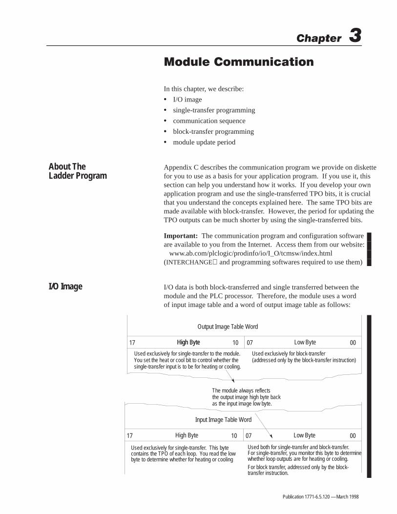
I/O data is both block-transferred and single transferred between themodule and the PLC processor. Therefore, the module uses a wordof input image table and a word of output image table as follows:
Output Image Table Word
Input Image Table Word
High Byte Low Byte
High Byte Low Byte 000710
17
High Byte
000710
17
Used exclusively for single-transfer to the module. You set the heat or cool bit to control whether thesingle-transfer input is to be for heating or cooling.
Used exclusively for block-transfer (addressed only by the block-transfer instruction)
Used both for single-transfer and block-transfer. For single-transfer, you monitor this byte to determinewhether loop outputs are for heating or cooling.For block transfer, addressed only by the block-transfer instruction.
Used exclusively for single-transfer. This bytecontains the TPO of each loop. You read the lowbyte to determine whether for heating or cooling
The module always reflects the output image high byte backas the input image low byte.
About The Ladder Program
I/O Image

3–2 Module Communication
Publication 1771-6.5.120 — March 1998
!ATTENTION: If the module is located in an I/Ochassis (with a 1771-ASB I/O adapter) on a universalremote I/O link, you can not make use of its single-transferred I/O data to control both heating and coolingelements because the single-transfer TPO signal may beunreliable. However, if the module is located in a localI/O chassis (processor-resident or extended local) or inan I/O chassis (with a 1771-ACN I/O adapter) on aControlNet link or is used for heat-only control, youcan make use of single-transferred I/O data.
Single-transfer of I/O data occurs automatically in each I/O scan. Thatis, a single unit of I/O data can be exchanged between each I/O moduleand its corresponding address in the I/O image table. The size of the unitof I/O data available for transfer to/from each I/O module is determinedby the I/O addressing mode you selected for the I/O chassis. The moduleuses 16 bits of input image and 16 bits of output image. Therefore, theI/O chassis must be set for either 1-slot or -slot addressing.
Control Bits
The meaning of the control bits in the high byte of the output imageword and the low byte of the input image word are as follows.
17 16 15 14 13 12 11 10
1 0 01 = OK
1 = Heat1 = Cool
High byte of output image wordLow byte of input image word
00
07 06 05 04 03 02 01 00
0 = Watchdog time-out
The ladder logic must:
1. Set bits of the high byte of the output image word to tell themodule whether to send TPO bits (outputs) for heating or coolingfor the 8 loops.
2. Monitor the low byte of the input image word to determinewhether the module has sent outputs for heating or cooling.
3. Based on step 2, move TPO bits from the high byte of the inputimage word to the output image byte of other output modulescontrolling heating or cooling.
Single-TransferProgramming

3–3Module Communication
Publication 1771-6.5.120 — March 1998
Your ladder logic must set this bit patterninto the high byte of output image word.
17 16 15 14 13 12 11 10
0 1100010
The module copies this bit pattern intothe low byte of input image word unlessa block-transfer is in processs or awatchdog time-out is detected,
07 06 05 04 03 02 01 00
The bit pattern that appears in the low bytedetermines whether the high byte TPO bitsare for heating or cooling.
0 1100010
0 1010010
0 1010010
Output image word
Input image word
Bit pattern for cool control
Bit pattern for heat control
15 14 13 12 11 10 09 08
07 06 05 04 03 02 01 00
Bit pattern for cool control
Bit pattern for heat controlTPO bits for 8 temperature control loops.Function of heating or cooling is deter-mined by the bit pattern in the low byte.
High byte Low byte
Low byteHigh byte
Important: In reading the low byte of the input image word, if theladder logic detects bits 7, 6, and 0 to be off (watchdog time-out) itmust turn off all heat and cool outputs. At that point you must:
• cycle power (off then on) to the module
• reconfigure the module
If the watchdog timer bit stays off, replace the module.
TPO Bits
The loop designations of the heat/cool TPO bits in the high byte ofthe input image word are as follows.
17 16 15 14 13 12 11 10
Loop 1Loop 2
Loop 3
Heat/cool TPO bits inhigh byte of input image word
Loop 4Loop 5
Loop 6
Loop 8Loop 7

3–4 Module Communication
Publication 1771-6.5.120 — March 1998
Controlling Heating Elements Only
In single-transfer heating applications, the ladder logic must write toand read from the module’s I/O image table words as follows:
Write the decimal value 35 (binary 00100011) to the high byteof the output image word.
Read the low byte of the input image word.
If the low byte has the value 3510, move the value from thehigh byte of the input image word to the output image byte ofthe output module driving the heating elements.
If bit 0 (watchdog timer) of the low byte of the input image wordis off, zero the output image byte of the output module drivingthe heating elements.If bit 0 (watchdog timer) of the low byte of the input image wordis on and the low byte of the input image word does not havethe value 3510, do not write to the output image byte of theoutputs driving the heating elements.
High byte of module’soutput word
Low byte of module’sinput word
High byte of module’sinput word
Heating-element outputs(separate output module)
Heating-element outputs(separate output module)
3510?
3510
000000002
The following shows ladder logic to handle data single-transferredto/from the module in an application where the TPO of each loop isused only for heating.
BTDBIT FIELD DISTRIBSource
Source bitDest
I:00135
8O:002
Dest bitLength
008
BTDBIT FIELD DISTRIBSource
Source bitDest
35
0O:001
Dest bitLength
998488
MEQMASKED EQUALSource
Mask
I:00135
00FF
Compare 35
I:001
7
BTDBIT FIELD DISTRIBSource
Source bitDest
0
0O:002
Dest bitLength
008
This rung examines the low byte of themodule’s input image word to see if it isequal to 3510. If true, it copies the highbyte of the module’s input image word tothe output image byte of an outputmodule driving the heating elements.
This rung unconditionally writes the value3510 to the high byte of the module’s inputimage word.
If the module’s watchdog timer bit is off,this rung zeros the output image byte ofthe outputs driving the heating elements.
Since this instruction is designed primarilyfor use with integer source and destinationwords, the source bit and destination bitmust be designated in decimal. In thesecases you would enter 810 to designate bit108 of the I/O image word
I:001
6
I:001
0
In this example:
• the module and another output module driving the heating ele-ments are in the same I/O chassis with the PLC-5 processor
• the chassis is set for 1-slot addressing
• the module is in slot 1 (I/O group 1)
• the module driving the heating elements is in slot 2 (I/O group 2)

3–5Module Communication
Publication 1771-6.5.120 — March 1998
Controlling Heating and Cooling Elements
In single-transfer applications for heating and cooling, ladder logicmust write to and read from the module’s I/O image table words asfollows:
Write the decimal value 35 (binary 00100011) to the high byteof the output image word.
Read the low byte of the input image word.
If the low byte of the input image word has the value 3510, movethe value from the high byte of the input image word to theoutput image byte of the outputs driving the heating elements.
If bit 0 (watchdog timer) of the low byte of the input image wordis off, zero both of the output image bytes of outputs drivingheating and cooling elements.
If bit 0 (watchdog timer) of the low byte of the input image wordis on and the low byte of the input image word does not havethe value 3510 or 3710, do not write to the output image byte ofthe outputs driving the heating elements.
High byte of module’soutput word
Low byte of module’s input word
High byte of module’sinput word
Heating-element outputs(separate output module)
Heating-element outputs(separate output module)
3510?
3510
000000002
Write the decimal value 37 (binary 00100101) to the high byteof the output image word.
Read the low byte of the input image word.
If the low byte of the input image word has the value 3710, movethe value from the high byte of the input image word to theoutput image byte of the outputs driving the cooling elements.
High byte of module’soutput word
Low byte of module’sinput word
High byte of module’sinput word
Cooling-element outputs(separate output module)
3710?
3710
Cooling-element outputs(separate output module)
000000002
Write the decimal value 35 (binary 00100011) to the high byteof the output image word.
High byte of module’soutput word3510
Loop back to step 2.
Step 2
Step 3
Step 4
Step 5
Step 6
Step 7
Step 8
Step 9
Step 10
Step 1
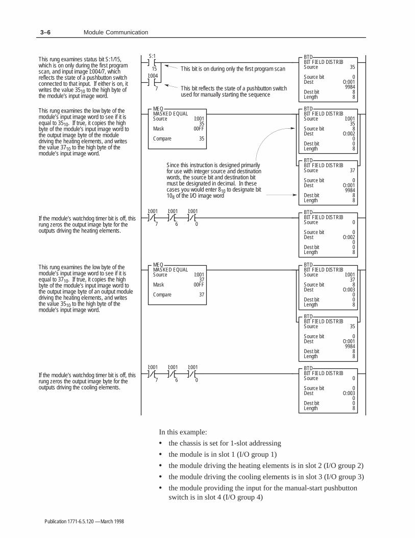
The key to this logic is the switching between reading heat bits andreading cool bits from the same input image byte. The followingfigure shows an example of PLC-5 ladder logic to handle datasingle-transferred to/from the module in an application where theTPO of each loop is used for both heating and cooling.
The module, the output modules driving the heating and coolingelements, and the input module providing the input for the manual-start pushbutton switch are in the same I/O chassis with the PLC-5processor.
3–6 Module Communication
Publication 1771-6.5.120 — March 1998
BTDBIT FIELD DISTRIBSource
Source bitDest
I:00135
8O:002
Dest bitLength
008
BTDBIT FIELD DISTRIBSource
Source bitDest
37
0O:001
Dest bitLength
998488
MEQMASKED EQUALSource
Mask
I:00135
00FF
Compare 35
BTDBIT FIELD DISTRIBSource
Source bitDest
0
0O:002
Dest bitLength
008
This rung examines the low byte of themodule’s input image word to see if it isequal to 3510. If true, it copies the highbyte of the module’s input image word tothe output image byte of the moduledriving the heating elements, and writesthe value 3710 to the high byte of themodule’s input image word.
If the module’s watchdog timer bit is off, thisrung zeros the output image byte for theoutputs driving the heating elements.
BTDBIT FIELD DISTRIBSource
Source bitDest
I:00137
8O:003
Dest bitLength
008
BTDBIT FIELD DISTRIBSource
Source bitDest
35
0O:001
Dest bitLength
998488
MEQMASKED EQUALSource
Mask
I:00137
00FF
Compare 37
BTDBIT FIELD DISTRIBSource
Source bitDest
0
0O:003
Dest bitLength
008
This rung examines the low byte of themodule’s input image word to see if it isequal to 3710. If true, it copies the highbyte of the module’s input image word tothe output image byte of an output moduledriving the heating elements, and writesthe value 3510 to the high byte of themodule’s input image word.
If the module’s watchdog timer bit is off, thisrung zeros the output image byte for theoutputs driving the cooling elements.
Since this instruction is designed primarilyfor use with integer source and destinationwords, the source bit and destination bitmust be designated in decimal. In thesecases you would enter 810 to designate bit108 of the I/O image word
S:1
15
BTDBIT FIELD DISTRIBSource
Source bitDest
35
0O:001
Dest bitLength
998488
I:004
7
This rung examines status bit S:1/15,which is on only during the first programscan, and input image I:004/7, whichreflects the state of a pushbutton switchconnected to that input. If either is on, itwrites the value 3510 to the high byte ofthe module’s input image word.
This bit is on during only the first program scan
This bit reflects the state of a pushbutton switchused for manually starting the sequence
I:001
7
I:001
6
I:001
0
I:001
7
I:001
6
I:001
0
In this example:
• the chassis is set for 1-slot addressing
• the module is in slot 1 (I/O group 1)
• the module driving the heating elements is in slot 2 (I/O group 2)
• the module driving the cooling elements is in slot 3 (I/O group 3)
• the module providing the input for the manual-start pushbuttonswitch is in slot 4 (I/O group 4)

3–7Module Communication
Publication 1771-6.5.120 — March 1998
The module can be configured for different types of applications andset for different modes of operation. Ladder logic for your applicationmust provide the proper sequence of block-transfer and single-transfercommunication with the module to provide desired control. Here weexplain the operation of the communication program (appendix C) thataccompanied the module. We suggest that you use it as the foundationof your application program.
Communication from start-up (without auto-tuning):
1. Download the configuration block.With each loop configuration block configured for your application,set download request bits (N7:0/00-07). Set them all at once (forall active loops) with your programming terminal or with ladderlogic that you write. (Prior to sending it the configuration block,the module will function in monitor mode, but with the defaultconfiguration listed in appendix B).
2. Download the gains block.With loop gains configured for your application, set the downloadrequest bit (N7:0/10) to establish PID gains.
3. Read status blocks.The communication program (appendix C) reads loop temperaturedata from the module at regular timed intervals.
4. If desired, change module operation.If you want to change module operation, modify the dynamicblock to command the changes. It is downloaded at regular timedintervals (just as the status block is returned at regular intervals.)
5. If using single-transfer, your ladder logic must write (map) thesingle-transferred TPO bits in word N7:9 to the output imagetable addresses of modules controlling your heat/cool outputs.This may occur whenever the low byte of the input imageindicates heat/cool TPO bits are available in the high byte (whenthe module is not processing block transfers).
Write configurationblock
Start
Write gains block
Read status block
Change mode, set point
etc. ?
Write dynamic block
Yes
No
Communication Sequence

3–8 Module Communication
Publication 1771-6.5.120 — March 1998
Communication from start-up (with auto-tuning):
Important: So as NOT to clear the gains block on first scan, you maywant to modify the initialization logic (rung 2) of the communicationprogram (appendix C) that accompanied the module. Look for themove (MOV) instruction having a source of 511 and a destination ofN7:0. Change the source of 511 to 255 to omit the gains block fromthe initialization download (refer to page C-10).
1. Download the configuration block.With each loop configuration block configured for your applicationincluding the selected loop auto-tuning response (word 2 bits 8, 9),set configuration block download request bits (N7:0/00-07) to sendloop configurations to the module.
2. Start auto-tuning.Set the dynamic block for running the module with loop auto-tuningbits On and with the module’s auto-tuning bit On (word 33, bit 1 = 1).The communication program (appendix C) downloads the dynamicblock periodically..
3. Reset the auto-tuning bit.Reset the module’s auto-tuning bit (word 33, bit 1 = 0) in thedynamic block. It is downloaded automatically.
4. Read status blocks.The communication program (appendix C) reads module status todetermine when auto-tuning is complete for each loop.When a loop’s auto-tuning is complete:
• set N7:0/09 to read the loop’s auto-tune block and store thevalues measured during auto-tuning.
• set N7:0/11 to read the loop’s gain block and store the newPID gains derived from auto-tuning
5. If you want to fine-tune PID gains, adjust them in the gains block.Then set the gains download request bit (N7:0/10) to send thePID gains block to the module.
6. If you want to change module operation, set desired commandbits in the dynamic block. It is downloaded automatically.
7. If using single-transfer, your ladder logic must write (map) thesingle-transferred TPO bits in word N7:9 to the output imagetable addresses of modules controlling your heat/cool outputs.This may occur whenever the low byte of the input imageindicates heat/cool TPO bits are available in the high byte (whenthe module is not processing block transfers).
Write configurationblock
Start
Change mode, set point
etc. ?
Yes
Write dynamic blockto start A-T
Write dynamic block toreset to 0 invoke A-T bit
Read status block
A-Tcomplete
?
Read A-T block
Read gains block
Read status block
Write dynamic block
No
Yes
No
Fine-tune gains
?
Write gains block
No
Yes

3–9Module Communication
Publication 1771-6.5.120 — March 1998
Re-start after power loss after auto-tuning:(because the module’s memory is volatile, after a power loss, themodule configuration and tuning values must be restored)
1. Write (block-transfer) the configuration block for each loop to themodule to ensure the correct loop configuration.
2. Write (block-transfer) the auto-tuning block to the module. Thiswill trigger the module to use these values to calculate the PIDparameters and provide the start-up algorithm.
3. If you don’t want to use the gains derived from the auto-tuningparameters, change the gains in the gains block and write(block-transfer) the gains block to the module.
4. Read (block-transfer) the system status block from the module tomonitor the loops.
5. Write (block-transfer) the dynamic block to the module to controlthe loops.
If the module is located in an I/O chassis (with a 1771-ACN I/Oadapter) on a ControlNet link, use unscheduled transfers to transfer theblocks of data (refer to publication 1785-6.5.14). Unless the module islocated in an I/O chassis (with a 1771-ACN I/O adapter) on aControlNet link, you must use block- transfer instructions to transferthe blocks of data. To generate a block- transfer to the module, yourladder logic must execute a block- transfer write instruction. Togenerate a block-transfer from the module, your ladder logic mustexecute a block-transfer read instruction.
Enter the rack number and group number based on the module’sphysical location as with any other block-transfer module. The moduleentry specifies the byte (0 or 1) of the I/O image word. Although themodule uses a full word of I/O image space, the low byte of themodule’s I/O image word is used for block-transfer. Therefore, in theblock-transfer instruction, you must address the module as module 0.
BTRBLOCK TRANSFER READRackGroupModuleControl block
0
Data FileLengthContinuous
Always enter module 0
The communication program (appendix C) or your ladder logic (if notusing appendix C) will need to execute the block-transfer writeinstruction whenever necessary to transfer the specific write blocks tothe module. The logic will need to execute the block-transfer read
Write configurationblock
Re-start
Change mode, set point
etc. ?
Write A-T block
Read status block
Write dynamic block
No
Yes
Fine-tune gains
?
Write gains block
No
Yes
Block-TransferProgramming
3–10 Module Communication
Publication 1771-6.5.120 — March 1998
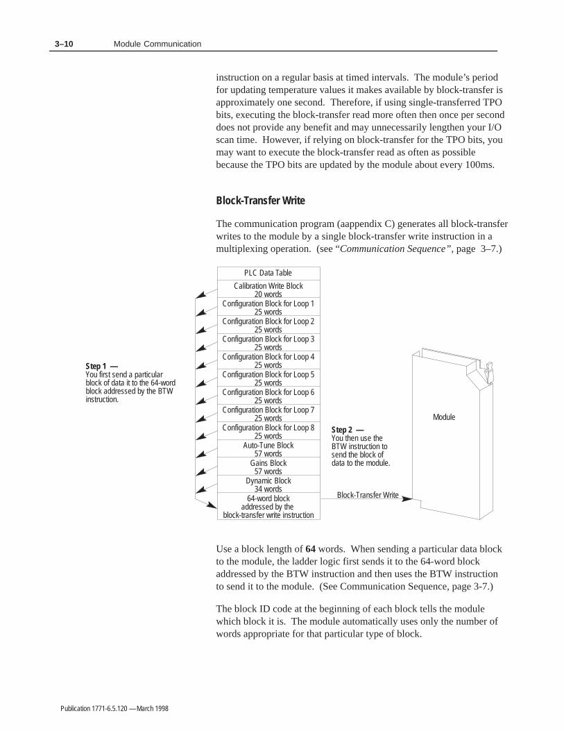
instruction on a regular basis at timed intervals. The module’s periodfor updating temperature values it makes available by block-transfer isapproximately one second. Therefore, if using single-transferred TPObits, executing the block-transfer read more often then once per seconddoes not provide any benefit and may unnecessarily lengthen your I/Oscan time. However, if relying on block-transfer for the TPO bits, youmay want to execute the block-transfer read as often as possiblebecause the TPO bits are updated by the module about every 100ms.
Block-Transfer Write
The communication program (aappendix C) generates all block-transferwrites to the module by a single block-transfer write instruction in amultiplexing operation. (see “Communication Sequence”, page 3–7.)
Configuration Block for Loop 225 words
Configuration Block for Loop 125 words
Configuration Block for Loop 325 words
Configuration Block for Loop 425 words
Configuration Block for Loop 525 words
Configuration Block for Loop 625 words
Configuration Block for Loop 725 words
Configuration Block for Loop 825 words
Gains Block57 words
Calibration Write Block20 words
64-word blockaddressed by the
block-transfer write instruction
Auto-Tune Block57 words
Module
PLC Data Table
Block-Transfer Write
Step 1 — You first send a particularblock of data it to the 64-wordblock addressed by the BTWinstruction.
Step 2 — You then use theBTW instruction tosend the block ofdata to the module.
Dynamic Block34 words
Use a block length of 64 words. When sending a particular data blockto the module, the ladder logic first sends it to the 64-word blockaddressed by the BTW instruction and then uses the BTW instructionto send it to the module. (See Communication Sequence, page 3-7.)
The block ID code at the beginning of each block tells the modulewhich block it is. The module automatically uses only the number ofwords appropriate for that particular type of block.

3–11Module Communication
Publication 1771-6.5.120 — March 1998
Block-Transfer Read
All block-transfer reads from the module are generated by a singleblock-transfer read instruction. Use a block length of 64 words. Whena data block is received in the 64-word block addressed by the block-transfer read instruction, the ladder logic first reads the block ID code,and then based on the ID, sends the data block to the appropriateaddress for that particular type of block
Auto-Tune Block57 words
Status Block64 words
64-word blockaddressed by the
block-transfer read instruction
Gains Block57 words
Module
PLC Data Table
Block-Transfer Read
Step 2 — The logic reads the block ID in the64-word block addressed by the BTRinstruction, and based on the ID,sends the block to the appropriateaddress for that particular type ofdata block.
Step 1 — The BTR instructionbrings the data blockfrom the module.
Calibration Block14 words
In the dynamic block (word 33, bits 0 & 6), you specify whether themodule should send back a gains block, auto-tune block, or statusblock in subsequent block-transfer reads.
The module updates TPO data for single-transfer on a shorter timeperiod than it updates data for block-transfer.
• The module’s period for updating the heat only and cool only TPObits it makes available thru single-transfer is approximately 10ms. If you alternately examine heating and cooling TPO bits, the effectiveperiod for updating heat and cool TPO bits is approximately 20ms.
• The module’s period for updating the heat and cool TPO bits itmakes available thru block-transfer is approximately 100ms.
• The module’s period for updating the temperature values it makesavailable thru block-transfer is 1 second.
• The module’s period for updating the outputs it makes availablethru block-transfer for heating is set by the heat TPO period youenter in the configuration block (word 11).
• The module’s period for updating the outputs it makes availablethru block-transfer for cooling is set by the cool TPO period youenter in the configuration block (word 13).
System Status Block
ModulePLC Data Table
Block-Transfer Read *
PIDAlgorithm
Input Byte Update every 10ms
Update every 10ms
Update every second
TPO Bits
TPO Bits
Temperature ValuesSystem Status Block
Single-Transfer *
* The time required for single-transfer and block-transfer depend on the specific PLC system configuration.
Module Update Period

3–12 Module Communication
Publication 1771-6.5.120 — March 1998
Notes:

Publication 1771-6.5.120 — March 1998
This chapter shows you how to independently configure each of theeight temperature control loops. This includes:
• block identification
• open-circuit detection
• barrel/non-barrel control
• inner/outer zone
• thermal integrity loss detection
• alarms
• alarm dead band
• loop operational mode
• inferred decimal point
• the configuration block
The first word of each block contains a block identification code thatyou use to tell the module that it is a configuration block and thatyou use to tell the module which loop the block is to configure.
If a loop input circuit becomes open (a wire breaks or vibrates loose)the loop can not measure the temperature. In automatic mode, thelack of temperature feedback would make it impossible to control thetemperature. To guard against such a lack of temperature control,the module provides open-circuit detection.
With bits 1 and 2 of word 1 of the configuration block, you select amode to which the loop is to switch when an open input circuit isdetected in automatic mode. The selections are:
• disable the PID loop by forcing M to zero
• set the output (M) to the open-circuit forced value (set in word 8)
• set the loop to the manual mode (force M to manual output value)
Note: For consistency and to comply with ISA/IEE terminology, we have changed terminology in this manual as follows:
Previous terminology: Changed to: Meaning:
CV (control variable) M (manipulated variable) loop output
PV (process variable) C (controlled variable) loop input
Block Identification
Open-Circuit Detection

4–2 Configuring the Module
Publication 1771-6.5.120 — March 1998
With bit 12 of word 2, you select between barrel and non-barrelcontrol. Barrel control can be used for either heat-only or heat/coolapplications. Non-barrel control can be use for either heat-only, coolonly, or heat/cool applications.
Barrel control is for multiple-zone applications in which there isthermal conduction between the zones. Injection molding andextruding are good examples of this because there are multiple heaterbands (zones) mounted on one thermal conductor (the metal barrel).The barrel conducts heat between the different zones. If you selectbarrel control, with bit 11 of word 2, must also select between innerand outer zone. If you select barrel control, word 24 does not apply.A barrel loop is auto-tuned as the temperature rises from ambient toa fixed set-point during startup.
Non-barrel control is for independent loops with no thermalconduction between the zones. If you select non-barrel control, theinner/outer zone selection of bit 11 of word 2 does not apply. If youselect non-barrel control, the loop is auto-tuned as it reacts to theset-point disturbance you enter in word 24.
Switch to Barrel Control?
For some applications, even though the loops are independent with nothermal conductivity between zones, barrel control may provide betterperformance than non-barrel control. If a loop has any of thesecharacteristics, you may want to try switching it to barrel control.
• time constant is greater than 100.0 seconds(You can read the time constant for each loop in the auto-tune block.)
• loop has a problem overshooting the set point
• loop output is saturating (M at 100%) for a significant duration
If you switch a loop to barrel control for one of these reasons, select it to be an outer zone.
!ATTENTION: If you switch a loop betweennon-barrel control and barrel control, you mustauto-tune the loop again before operating it. If you failto auto-tune the loop after making such a switch, theauto-tuning values will be wrong for the applicationand the gains will be greatly distorted.
Barrel/Non-Barrel Control

4–3Configuring the Module
Publication 1771-6.5.120 — March 1998
If you make the selection for barrel temperature control, you alsohave a selection for whether it is an inner zone or an outer zone. Anouter zone is a zone at either end of the barrel. An inner zone is anyzone other than at the very end of the barrel (between two otherzones). The PID gain calculation algorithm for an inner zone isslightly different from that for an outer zone to account for an innerzone being more affected by adjacent zones. The inner zones aretreated as more of an integrating process than are outer zones.
ÍÍ
ÍÍ
ÍÍ
ÍÍ
ÍÍ
ÍÍ
ÍÍ
ÍÍ
Í
Í
ÍÍ
ÍÍ
ÍÍ
ÍÍ
HnH1 H2 H3
Nozzle Zone 1 Zone 2 Zone 3
Ts Tn T1 T2 T3 TfT = temperature measurement point (thermocouple)H = heater band (element)
Typical plastic injection barrel with multiple temperaturezones
Ram(Screw)
OuterZone
OuterZone
InnerZone
InnerZone
The loss of thermal integrity is detected when the loop output (M) isat 100% while the temperature rate of change measured by themodule is below the minimum expected rate. Detecting the loss ofthermal integrity requires an assumption of a minimum rate of changein the temperature input value (C) when the output (M) is at 100%.An example of a loss of thermal integrity could be because thecontactor for a heating band fails open; or the sensor is not in properposition to measure the true temperature.
The values you enter into words 21 and 22 establish a minimum rateof change (°/min) in the temperature input (C) that you will allowwhen the output (M) is at 100%. The temperature change value youenter in word 21 divided by the period value you enter in word 22 isthe thermal integrity rate. With bits 4 and 5 of word 1 of theconfiguration block, you select a mode for switching the output (M) toa forced value when the rate of change of the temperature input (C)does not reach the minimum for thermal integrity. The selections are:
• disable the PID loop by forcing M to zero
• set output (M) to the thermal runaway forced value (set in word 9)
• set the output (M) to the manual-mode value by setting the loopinto manual mode
Once a thermal integrity is detected, to clear this condition, you mustdisable the affected loop and then re-enable it (bits 7 and 8 of word 1).
Inner/Outer Zone
Thermal Integrity LossDetection (formerly calledthermal runaway)

4–4 Configuring the Module
Publication 1771-6.5.120 — March 1998
In the configuration block you select values for the followingtemperature-level alarms:
• low temperature alarm (word 16)
• high temperature alarm (word 17)
• low deviation alarm (deviation from the set point)(word 18)
• high deviation alarm (deviation from the set point)(word 19)
Low TemperatureAlarm Value
Low DeviationAlarm Value
SetPoint
High TemperatureAlarm Value
High DeviationAlarm Value
0°Time
Tem
pera
ture
Once the temperature alarm bits are on, they are kept on until thetemperature drops below the high alarm by the alarm dead-bandvalue or rise above the low alarm by this value. You specify thetemperature alarm dead band in word 20. It applies to the C value atthe high and low temperature alarms and deviation alarm values.The dead band provides a hysteresis effect.
• Low Alarm With Dead Band — When the temperature fallsbelow the user-defined low alarm value, the low alarm bit isturned on. When the temperature rises above the level of the lowalarm value but still below the level of the dead-band value, thelow alarm bit remains on. Only when the temperature rises abovethe dead-band level will the alarm bit be turned off.
• High Alarm With Dead Band — When the temperature risesabove the user-defined high alarm value, the high alarm bit isturned on. When the temperature falls below the level of the highalarm value but still above the level of the dead-band value, thehigh alarm bit remains on. Only when the temperature falls be-low the dead-band level will the alarm bit be turned off.
High Alarm Level
Low Alarm Level
TimeTimealarm on
Important: The temperature passes thru the dead band before the alarm is turned on or offto provide stability to alarm indicators. Dead bands apply to C and deviation alarms.
without dead band with dead band
alarm off
dead band
dead band
Tem
pera
ture
(C value)
Alarms
Alarm Dead Band

4–5Configuring the Module
Publication 1771-6.5.120 — March 1998
In the configuration block (bits 7 and 8 of word 1) you selectbetween disabling the loop, only monitoring the loop, or a controlmode for the loop. If in the configuration block you select controlmode, in the dynamic block you can select between:
• disabling loop control (monitor only)
• enabling manual control mode
• enabling automatic PID control mode
Configuration Block Selections
Disable the Loop
Monitor the Loop
Control the Loop
Dynamic Block Selections
Disable Loop Control
Enable Loop Control
Automatic Mode
Loop Operation
Hold M=0, and no temperature or alarms.
Hold M=0, but monitor temperatureand provide temperature and alarmsin the status block.
The manual output value in the configu-ration block is used as the M value.
The PID algorithm generates the M value.
Manual Mode
For words 3 thru 19, you enter a 16-bit signed integer value.However, as you enter the value you must be aware of an inferreddecimal point.
• For these values in words 3 and 6 thru 13, the inferred decimalpoint is 2 places from the right (causing the resolution to be 0.01).For example, if in word 6 you enter the value 4999, the moduleinfers the value to be 49.99.
• For the temperature values in words 15 thru 20, the inferreddecimal point is 1 place from the right (causing the resolution to be 0.1). For example, if in word 16 you enter a value of 4999, themodule infers the value to be 499.9. Also, for each of these values,the range is dependant upon the type of thermocouple used. Therange for each type of thermocouple is specified in appendix A.
Loop Operational Mode
Inferred Decimal Point

4–6 Configuring the Module
Publication 1771-6.5.120 — March 1998
The following table describes the 25-word configuration block. The IDcode in word 0 identifies the loop. Default values are shown in italics.
Word Bits Description
0 0–15 Block Identification Codebit 15 . . . . . . . . . . . bit 0• loop 1 = 1000 1000 0000 0001 (880116)(–3071910)• loop 2 = 1000 1000 0000 0010 (880216)(–3071810)• loop 3 = 1000 1000 0000 0011 (880316)(–3071710)• loop 4 = 1000 1000 0000 0100 (880416)(–3071610)• loop 5 = 1000 1000 0000 0101 (880516)(–3071510)• loop 6 = 1000 1000 0000 0110 (880616)(–3071410)• loop 7 =1000 1000 0000 0111 (880716)(–3071310)• loop 8 = 1000 1000 0000 1000 (880816)(–3071210)
1 0 Always = 0.
1–2 Open-Circuit Detection Configuration (for 2-wire sensors*) — When an open input circuit is detected (if auto mode hadbeen selected in the dynamic block), the operating mode is switched to:bit 2 bit 1 selection• 0 0 = Disable PID loop (M = 0)• 0 1 = Set output to open-circuit forced M value (set in word 8).• 1 0 = Set output to manual-mode M value.• 1 1 Do not use this selection. It will freeze the output at the current M value. However, the M value will have
already moved to beyond a satisfactory value before the open circuit is detected.
* For a 3-wire RTD, the software is designed to detect an open-sensor condition.)
3 Always = 0.
4–5 Thermal Integrity Loss Configuration — When a loss of thermal integrity is detected, the operating mode is set as:bit 5 bit 4 selection• 0 0 = Disable PID loop (M = 0)• 0 1 = Set output to thermal-integrity-loss forced M value (set in word 9).• 1 0 = Set output to manual-mode M value.• 1 1 is not used (illegal value).
6 Always = 0.
7–8 Loop Operational Modebit 8 bit 7 selection• 0 0 = Monitor input to indicate temperature and alarms, but no control of M value (M value held at 0).• 0 1 = Control mode (disable, manual, or automatic PID control of loop as directed in the dynamic block).• 1 0 = Disable loop (M=0, and no temperature value or alarms).• 1 1 is not used (illegal value).
9–11 Always = 000.
12–15 Thermocouple Type for TCM Modulebit 15 . . 12 selection• 0 0 0 0 = mV• 0 0 0 1 = B• 0 0 1 0 = E
(ignored by TCMR module) bit 15 . . 12 selection• 0 0 1 1 = J• 0 1 0 0 = K• 0 1 0 1 = R
bit 15 . . 12 selection
• 0 1 1 0 = S
• 0 1 1 1 = T
Configuration Block

4–7Configuring the Module
Publication 1771-6.5.120 — March 1998
Word DescriptionBits
2 0 Always = 0.
1 Control Action• 0 = Control action is — E = SP–C (Reverse acting)• 1 = Control action is — E = C–SP (Direct acting)
2–3 Always = 00.
4 Set Point Ramping Enable — Selects whether to use a fixed set-point ramp rate (set in word 3) for the current set point toreach the selected set point.• 0 = Disable set-point ramping.• 1 = Enable set-point ramping.
5–6 Always = 00.
7 Alarm Enable• 0 = Suppress all alarms.• 1 = Report all alarm conditions.
8–9 Desired System Response — At the completion of auto-tuning, the module calculates the PID gains based on the systemparameters it has just measured and this selection for the desired system response.bit 9 bit 8 selection• 0 0 = Slow (reach the set point slowly).• 0 1 = Medium (reach the set point faster without overshooting).• 1 0 = Fast (overshoot the set point).• 1 1 = Very fast.
10 Always = 0.
11 Zone Select — Applies only if barrel control is selected.• 0 = Inner zone.• 1 = Outer zone.
12 Barrel/Non-barrel Control• 0 = Barrel control.• 1 = Non-barrel control.
13 Input Filter Enable — Used with word 25.• 0 = Disable the input filter.• 1 = Enable the input filter.
14–15 Always = 000.
3 0–15 Set-Point Ramp Rate — If enabled by bit 4 of word 2, the rate (degrees/minute) at which the current set point is increased ordecreased to reach the selected set-point. (0.00 thru 99.99°/min)
4 0–15 Always = 0.
5 0–15 Always = 0.
6 0–15 High M Limit — The maximum M percentage allowable. (–100.00 thru +100.00) (If >0, heating is inferred.)
7 0–15 Low M Limit — The minimum M percentage allowable. (–100.00 thru +100.00) (If <0, cooling is inferred.) (default = 0.00)
8 0–15 Forced M Value on Open Circuit — The percentage value forced into the M when an open input circuit is detected. (–100.00 thru +100.00) (default = 0.00)
9 0–15 Forced M Value on Thermal Integrity Loss — The percentage value forced into the M when thermal integrity loss isdetected. (–100.00 thru +100.00) (default = 0.00)
10 0–15 Heat Minimum On Time — Minimum time in seconds that the heat bit is on during the TPO period. If the calculated time isless than this minimum, the heat bit will remain off. This value must be less than 5% of the heat TPO period. (0.00 thru 100.00)

4–8 Configuring the Module
Publication 1771-6.5.120 — March 1998
Word DescriptionBits
11 0–15 Heat TPO Period — The period in seconds at which the heat TPO bit is cycled and the M is updated. This value must be lessthan the system lag time. (0.00 thru 100.00s accepted but truncated to 0 thru 100s) (default = 5s)
12 0–15 Cool Minimum On Time — Minimum time in seconds that the cool bit is on during the TPO period. If the calculated time isless than this minimum, the cool bit will remain off. This value must be less than 5% of the cool TPO period. (0.00 thru 100.00)
13 0–15 Cool TPO Period — The period in seconds at which the cool TPO bit is cycled and the M is updated. This value must be lessthan the system lag time. (0.00 thru 100.00s accepted but truncated to 0 thru 100s) (default = 5s)
14 0–15 Auto-Tune Startup Aggressiveness — The lower the value, the longer the time to reach initial setpoint with less overshoot.The higher the value, the faster you reach initial setpoint but with greater overshoot. Optimum is an aggressiveness value thatreaches initial setpoint fast with tolerable overshoot. Has no affect after reaching initial setpoint (0-100 unit-less) default = 0.Important: For Heat/Cool operation only, the default value is 25.
15 0–15 C Alarm Rate — If the rate of temperature increase is greater than this value, the C rate alarm bit is turned on. A value of 0.0disables the C rate alarm. (–3276.8 thru 3276.7°/s)
16 0–15 Low Temperature Alarm Value — A C value at the low end of the sensor limit, but still above the minimum C value (–3276.8 thru 3276.7)
17 0–15 High Temperature Alarm Value — A C value at the high end of the sensor limit, but still below the max C value (–3276.8 thru 3276.7)
18 0–15 Low Deviation Alarm Value — A value that specifies the greatest deviation below the set point that the process can tolerate.(–3276.8 thru 3276.7)
19 0–15 High Deviation Alarm Value — A value that specifies the greatest deviation above the set point that the process can tolerate.(–3276.8 thru 3276.7°)
20 0–15 Temperature Alarm Dead Band — Once the temperature alarm bits are on, they are kept on until the temperature dropsbelow the high alarm by this value or rise above the low alarm by this value. The dead-band value applies to the high and lowtemperature and deviation alarm values. (0.0 thru 10.0°)
21 0–15 Thermal Integrity Temperature Change Value — This temperature-change value divided by the period is the thermalintegrity rate. (0 thru 100°) (default = 5°)
22 0–15 Thermal Integrity Period in Minutes — The temperature-change value divided by this period is the thermal integrity rate.(0 thru 100 min) (default = 20 min)
23 RTD Type for TCMR Module — (ignored by TCM module)
0-7 Offset for Cu RTD (–0.99 to +0.99 in units of 0.01 ohm) – Offset = resistance of RTD – 10.00.For example, if the Cu RTD is 9.74 ohms (at 25o C), the offset would be 9.74 – 10.00 = –0.26.
8–10 RTD Selection bit 10-9-8 selection• 0 0 0 = ohms• 0 0 1 = 100 ohm Pt (Euro)• 0 1 0 = 100 ohm Pt (USA)• 0 1 1 = 10 ohm Cu• 1 0 0 = 120 Ni
11–15 Reserved
24 0–15 Non-Barrel Auto-Tune Disturbance Size — The size of disturbance used to auto-tune if non-barrel is selected. For auto-tuning cool-only zones. Ignored for barrel zones. Entering 0.00 selects 100%. (0.00 thru 100.00%)
25 0-15 Time Constant for the Input Filter — The time constant in seconds that controls filtering of the temperature input.The larger the value, the more it will affect the response. Adjust the value just high enough to minimize spurious alarms. A value of zero disables the filter. (0.0 thru 9.9)
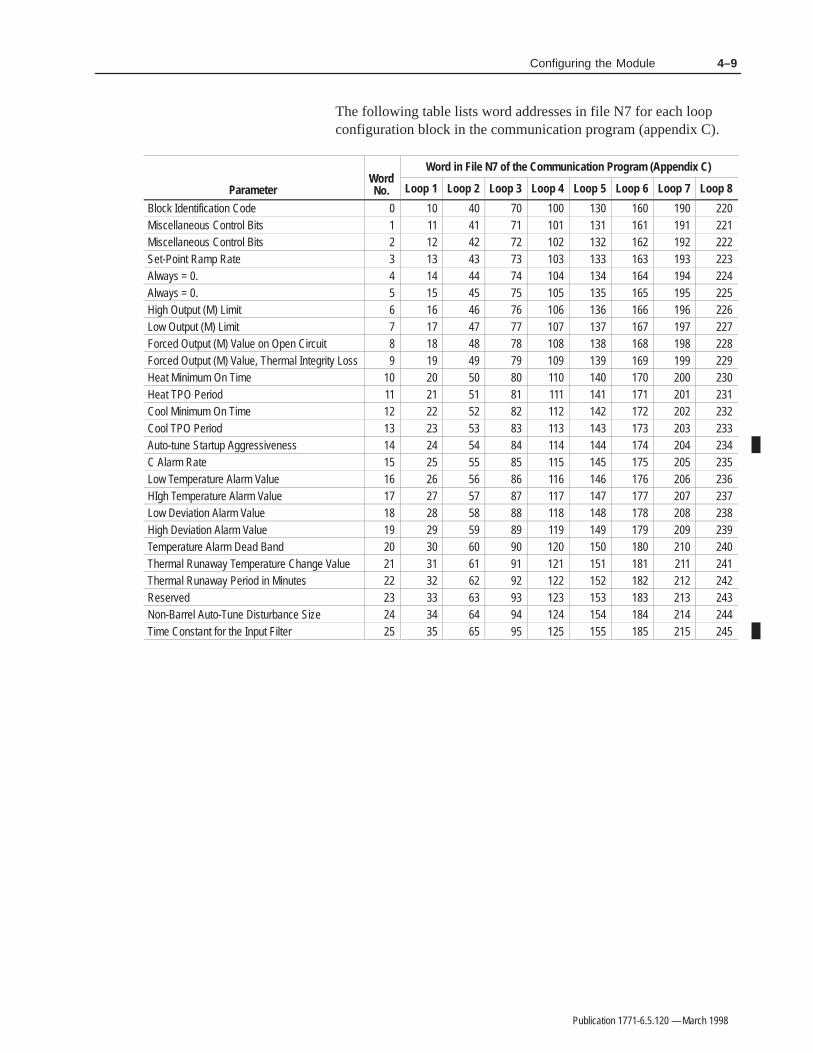
4–9Configuring the Module
Publication 1771-6.5.120 — March 1998
The following table lists word addresses in file N7 for each loopconfiguration block in the communication program (appendix C).
Wo dWord in File N7 of the Communication Program (Appendix C)
ParameterWordNo. Loop 1 Loop 2 Loop 3 Loop 4 Loop 5 Loop 6 Loop 7 Loop 8
Block Identification Code 0 10 40 70 100 130 160 190 220Miscellaneous Control Bits 1 11 41 71 101 131 161 191 221Miscellaneous Control Bits 2 12 42 72 102 132 162 192 222Set-Point Ramp Rate 3 13 43 73 103 133 163 193 223Always = 0. 4 14 44 74 104 134 164 194 224Always = 0. 5 15 45 75 105 135 165 195 225High Output (M) Limit 6 16 46 76 106 136 166 196 226Low Output (M) Limit 7 17 47 77 107 137 167 197 227Forced Output (M) Value on Open Circuit 8 18 48 78 108 138 168 198 228Forced Output (M) Value, Thermal Integrity Loss 9 19 49 79 109 139 169 199 229Heat Minimum On Time 10 20 50 80 110 140 170 200 230Heat TPO Period 11 21 51 81 111 141 171 201 231Cool Minimum On Time 12 22 52 82 112 142 172 202 232Cool TPO Period 13 23 53 83 113 143 173 203 233Auto-tune Startup Aggressiveness 14 24 54 84 114 144 174 204 234C Alarm Rate 15 25 55 85 115 145 175 205 235Low Temperature Alarm Value 16 26 56 86 116 146 176 206 236HIgh Temperature Alarm Value 17 27 57 87 117 147 177 207 237Low Deviation Alarm Value 18 28 58 88 118 148 178 208 238High Deviation Alarm Value 19 29 59 89 119 149 179 209 239Temperature Alarm Dead Band 20 30 60 90 120 150 180 210 240Thermal Runaway Temperature Change Value 21 31 61 91 121 151 181 211 241Thermal Runaway Period in Minutes 22 32 62 92 122 152 182 212 242Reserved 23 33 63 93 123 153 183 213 243Non-Barrel Auto-Tune Disturbance Size 24 34 64 94 124 154 184 214 244Time Constant for the Input Filter 25 35 65 95 125 155 185 215 245

4–10 Configuring the Module
Publication 1771-6.5.120 — March 1998
Notes:

Publication 1771-6.5.120 — March 1998
This chapter shows you how auto-tuning parameters are saved byreading the auto-tune block from the module; and restored by writingthe auto-tune block to the module.
This includes:
• sequence of block-transfers
• block identification
• inferred decimal point
• the auto-tune block
Important: Auto-tuning parameters are not PID gains, but are measuredprocess dynamics that the module uses to calculate PID gains (chapter 6).
Once auto-tuning is complete, ladder logic must read (block-transfer)the auto-tune block from the module to store it in PLC processormemory. The module’s memory is volatile. Whenever power to themodule is interrupted, unless you execute auto-tuning again, you mustagain send the auto-tuning block to the module. Writing the auto-tuneblock to the module establishes the start-up algorithm and the valuesthe module uses to calculate PID gains. However, you can override thegains calculated from auto-tuning by sending the gains block anytimeafter the auto-tune block.
In the dynamic block (bits 0 and 6 of word 33) you select which block(auto-tune, gains, or status) the module should send in response to ablock-transfer read instruction.
The first word of each auto-tuning block contains a block ID code(1000 1000 0000 1011, 880B16, or –3070910) that you use to tell themodule that it is an auto-tuning block.
Values are expressed as 16-bit integers with inferred decimal point.
• For each gain, the inferred decimal point is 2 places from the right(causing the resolution to be 0.01). For example, if in word 1 youenter the value 4999, the module infers the value to be 49.99.
• For each time constant, the inferred decimal point is 1 place fromthe right (causing the resolution to be 0.1). For example, if in word2 you enter the value 4999, the module infers the value to be 499.9.
• For each dead time, the inferred decimal point is 1 place from theright (causing the resolution to be 0.1). For example, if in word 3you enter the value 4999, the module infers the value to be 499.9.
Sequence ofBlock-Transfers
Block Identification
Inferred Decimal Point

5–2 Saving/Restoring Auto-Tuning Parameters
Publication 1771-6.5.120 — March 1998
The auto-tune block contains 57 words. We include correspondingword addresses in file N7 of the communication program (appendix C).These values are measured process dynamics that the module uses tocalculate PID gains. Descriptions are for barrel and non-barrel loops.
Program Addr: Word: Bits: Description for Barrel Loops: Description for Non-Barrel Loops:
420 0 0–15 Block Identification Code — 1000 1000 00001011 (880B16) (–3070910)
Block Identification Code — 1000 1000 00001011 (880B16) (–3070910)
421 1 0–15 Loop-1 Heat Slope (0.00 thru 327.67°/%/s) Loop-1 Heat Process Gain (0.00 thru 327.67°/%)422 2 0–15 Loop-1 Heat Time Constant (0.0 thru 3276.7s) Loop-1 Heat Time Constant (0.0 thru 3276.7s)423 3 0–15 Loop-1 Heat Dead Time (0.0 thru 3276.7s) Loop-1 Heat Dead Time (0.0 thru 3276.7s)424 4 0–15 Loop-1 Cool Slope (0.00 thru 327.67°/%/s) Loop-1 Cool Process Gain (0.00 thru 327.67°/%)425 5 0–15 Loop-1 Cool Time Constant (0.0 thru 3276.7s) Loop-1 Cool Time Constant (0.0 thru 3276.7s)526 6 0–15 Loop-1 Cool Dead Time (0.0 thru 3276.7s) Loop-1 Cool Dead Time (0.0 thru 3276.7s)427 7 0–15 Reserved Reserved428 8 0–15 Loop-2 Heat Slope (0.00 thru 327.67°/&/s) Loop-2 Heat Process Gain (0.00 thru 327.67°/%)429 9 0–15 Loop-2 Heat Time Constant (0.0 thru 3276.7s) Loop-2 Heat Time Constant (0.0 thru 3276.7s)430 10 0–15 Loop-2 Heat Dead Time (0.0 thru 3276.7s) Loop-2 Heat Dead Time (0.0 thru 3276.7s)431 11 0–15 Loop-2 Cool Slope (0.00 thru 327.67°/%/s) Loop-2 Cool Process Gain (0.00 thru 327.67°/%)432 12 0–15 Loop-2 Cool Time Constant (0.0 thru 3276.7s) Loop-2 Cool Time Constant (0.0 thru 3276.7s)433 13 0–15 Loop-2 Cool Dead Time (0.0 thru 3276.7s) Loop-2 Cool Dead Time (0.0 thru 3276.7s)434 14 0–15 Reserved Reserved435 15 0–15 Loop-3 Heat Slope (0.00 thru 327.67°/%/s) Loop-3 Heat Process Gain (0.00 thru 327.67°/%)436 16 0–15 Loop-3 Heat Time Constant (0.0 thru 3276.7s) Loop-3 Heat Time Constant (0.0 thru 3276.7s)437 17 0–15 Loop-3 Heat Dead Time (0.0 thru 3276.7s) Loop-3 Heat Dead Time (0.0 thru 3276.7s)438 18 0–15 Loop-3 Cool Slope (0.00 thru 327.67°/%/s) Loop-3 Cool Process Gain (0.00 thru 327.67°/%)438 19 0–15 Loop-3 Cool Time Constant (0.0 thru 3276.7s) Loop-3 Cool Time Constant (0.0 thru 3276.7s)440 20 0–15 Loop-3 Cool Dead Time (0.0 thru 3276.7s) Loop-3 Cool Dead Time (0.0 thru 3276.7s)441 21 0–15 Reserved Reserved442 22 0–15 Loop-4 Heat Slope (0.00 thru 327.67°/%/s) Loop-4 Heat Process Gain (0.00 thru 327.67°/%)443 23 0–15 Loop-4 Heat Time Constant (0.0 thru 3276.7s) Loop-4 Heat Time Constant (0.0 thru 3276.7s)444 24 0–15 Loop-4 Heat Dead Time (0.0 thru 3276.7s) Loop-4 Heat Dead Time (0.0 thru 3276.7s)445 25 0–15 Loop-4 Cool Slope (0.00 thru 327.67°/%/s) Loop-4 Cool Process Gain (0.00 thru 327.67°/%)446 26 0–15 Loop-4 Cool Time Constant (0.0 thru 3276.7s) Loop-4 Cool Time Constant (0.0 thru 3276.7s)447 27 0–15 Loop-4 Cool Dead Time (0.0 thru 3276.7s) Loop-4 Cool Dead Time (0.0 thru 3276.7s)448 28 0–15 Reserved Reserved449 29 0–15 Loop-5 Heat Slope (0.00 thru 327.67°/%/s) Loop-5 Heat Process Gain (0.00 thru 327.67°/%)450 30 0–15 Loop-5 Heat Time Constant (0.0 thru 3276.7s) Loop-5 Heat Time Constant (0.0 thru 3276.7s)451 31 0–15 Loop-5 Heat Dead Time (0.0 thru 3276.7s) Loop-5 Heat Dead Time (0.0 thru 3276.7s)452 32 0–15 Loop-5 Cool Slope (0.00 thru 327.67°/%/s) Loop-5 Cool Process Gain (0.00 thru 327.67°/%)453 33 0–15 Loop-5 Cool Time Constant (0.0 thru 3276.7s) Loop-5 Cool Time Constant (0.0 thru 3276.7s)454 34 0–15 Loop-5 Cool Dead Time (0.0 thru 3276.7s) Loop-5 Cool Dead Time (0.0 thru 3276.7s)455 35 0–15 Reserved Reserved456 36 0–15 Loop-6 Heat Slope (0.00 thru 327.67°/%/s) Loop-6 Heat Process Gain (0.00 thru 327.67°/%)457 37 0–15 Loop-6 Heat Time Constant (0.0 thru 3276.7s) Loop-6 Heat Time Constant (0.0 thru 3276.7s)458 38 0–15 Loop-6 Heat Dead Time (0.0 thru 3276.7s) Loop-6 Heat Dead Time (0.0 thru 3276.7s)459 39 0–15 Loop-6 Cool Slope (0.00 thru 327.67°/%/s) Loop-6 Cool Process Gain (0.00 thru 327.67°/%)460 40 0–15 Loop-6 Cool Time Constant (0.0 thru 3276.7s) Loop-6 Cool Time Constant (0.0 thru 3276.7s)461 41 0–15 Loop-6 Cool Dead Time (0.0 thru 3276.7s) Loop-6 Cool Dead Time (0.0 thru 3276.7s)462 42 0–15 Reserved Reserved
Auto-Tune Block
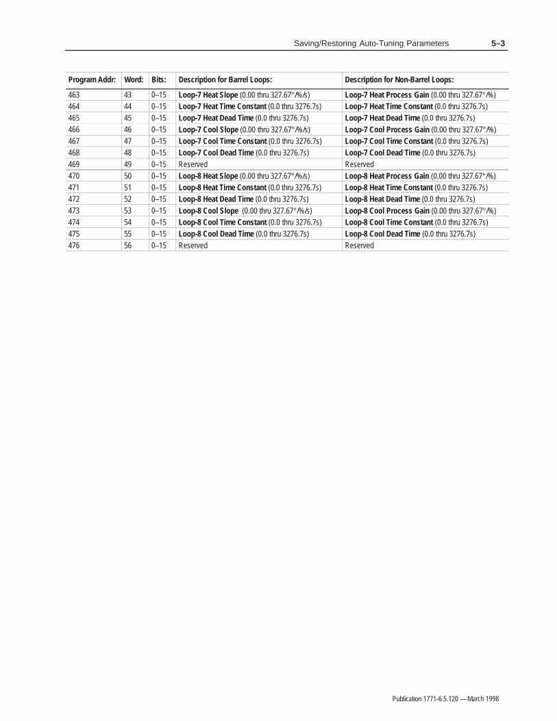
5–3Saving/Restoring Auto-Tuning Parameters
Publication 1771-6.5.120 — March 1998
Program Addr: Description for Non-Barrel Loops:Description for Barrel Loops:Bits:Word:
463 43 0–15 Loop-7 Heat Slope (0.00 thru 327.67°/%/s) Loop-7 Heat Process Gain (0.00 thru 327.67°/%)464 44 0–15 Loop-7 Heat Time Constant (0.0 thru 3276.7s) Loop-7 Heat Time Constant (0.0 thru 3276.7s)465 45 0–15 Loop-7 Heat Dead Time (0.0 thru 3276.7s) Loop-7 Heat Dead Time (0.0 thru 3276.7s)466 46 0–15 Loop-7 Cool Slope (0.00 thru 327.67°/%/s) Loop-7 Cool Process Gain (0.00 thru 327.67°/%)467 47 0–15 Loop-7 Cool Time Constant (0.0 thru 3276.7s) Loop-7 Cool Time Constant (0.0 thru 3276.7s)468 48 0–15 Loop-7 Cool Dead Time (0.0 thru 3276.7s) Loop-7 Cool Dead Time (0.0 thru 3276.7s)469 49 0–15 Reserved Reserved470 50 0–15 Loop-8 Heat Slope (0.00 thru 327.67°/%/s) Loop-8 Heat Process Gain (0.00 thru 327.67°/%)471 51 0–15 Loop-8 Heat Time Constant (0.0 thru 3276.7s) Loop-8 Heat Time Constant (0.0 thru 3276.7s)472 52 0–15 Loop-8 Heat Dead Time (0.0 thru 3276.7s) Loop-8 Heat Dead Time (0.0 thru 3276.7s)473 53 0–15 Loop-8 Cool Slope (0.00 thru 327.67°/%/s) Loop-8 Cool Process Gain (0.00 thru 327.67°/%)474 54 0–15 Loop-8 Cool Time Constant (0.0 thru 3276.7s) Loop-8 Cool Time Constant (0.0 thru 3276.7s)475 55 0–15 Loop-8 Cool Dead Time (0.0 thru 3276.7s) Loop-8 Cool Dead Time (0.0 thru 3276.7s)476 56 0–15 Reserved Reserved

5–4 Saving/Restoring Auto-Tuning Parameters
Publication 1771-6.5.120 — March 1998
Notes:

Publication 1771-6.5.120 — March 1998
This chapter shows you how to independently set the gains for eachof the eight PID loops. This includes:
• sequence of block-transfers
• auto-tuning the loops
• fine tuning the loops
• block identification
• inferred decimal point
• the gains block
Any time you cause successful auto-tuning of a loop, write anauto-tune block to the module, or write a gains block to the module,the module computes and stores a new set of PID gains.
At start-up, ladder logic must either write (block-transfer) the PIDgains block to the module or perform auto-tuning. If you selectauto-tuning, the module computes PID gains for each auto-tuned loop.Gains that you sent to the module previous to auto-tuning will besuperseded by PID gains derived from auto-tuning. Subsequent PIDgains blocks, read from the module, will contain the gains derivedfrom auto-tuning.
If the auto-tuning of a loop is not successful (as indicated in the statusblock) the loop gains you had sent before auto-tuning will be retainedand used by the module.
Once auto-tuning is complete, ladder logic must read (block-transfer)the gains block from the module to store it in PLC processor memory.When you want the module to switch from sending the block it hasbeen sending, you must send a dynamic block to establish themodule’s return of either an auto-tune, gains, or status block inresponse to block-transfer reads (selected by dynamic block word 33,bits 0 & 6).
The module’s memory is volatile. Whenever power to the module isinterrupted, you must re-establish PID gains: sending the auto-tuneblock establishes the start-up algorithm and the values the module usesto re-calculate PID gains which it does. However, you can override theauto-tune PID gains by sending the gains block after sending theauto-tune block.
Sequence ofBlock-Transfers
Auto-tuning causes the module tomeasure the process dynamics
and calculate PID gains.
Reading the gains block fromthe module copies the gainsgenerated by auto-tuning into
the PLC data table.
Writing the gains block to themodule overwrites any PIDgains that had been in the
module.
Auto-tuning or writing theauto-tune block to the modulecauses the module to calculate
PID gains and overwrite anyPID gains that had been in the
module.

6–2 Setting Proportional-Integral-Derivative Gains
Publication 1771-6.5.120 — March 1998
During auto-tuning, the module computes and stores PID gains. Youmay want to fine-tune the loops by manually adjusting PID gains.First adjust controller gain. It has the greatest impact. Then adjustintegral gain. The derivative gain should be the last adjustment forfine-tuning a loop.
If the loop over-shoots the setpoint either at start-up or at a change of setpoint, dampen the loop response as follows (in order of effectiveness):
1. decrease controller gain
2. decrease integral gain
3. increase derivative gain
If the loop is slow in reaching setpoint either at start-up or at achange of setpoint, improve the loop response as follows:
1. increase controller gain
2. increase integral gain
3. decrease derivative gain
The module provides dependant PID control action which can berepresented by the equation:
Where:M = Manipulated variableKc = Controller gain (no units)E = Error (SP–C or C–SP)Ki = Integral gain (repeats/second)Kd = Derivative gain (seconds)t = Time
The module performs PID control by computing the solution to anapproximation of the PID equation as follows:
Where:
Note: For consistency and to comply with ISA/IEE terminology, we have changed terminology in this manual as follows:
Previous terminology: Changed to: Meaning:
CV (control variable) M (manipulated variable) loop output
Kp (proportional gain) Kc (controller gain) module’s algorithm gain
Fine-Tuning the Loops
Set Point
Set Point
The PID Equation

6–3Setting Proportional-Integral-Derivative Gains
Publication 1771-6.5.120 — March 1998
The first word of each gains block contains a block ID code(1000 1000 0000 1001, 880916, or –3071110) that tells the modulethat it is a gains block.
For each gain value, you enter a 16-bit integer value. However, asyou enter each gain value, be aware of an inferred decimal point.
• For each proportional gain, the inferred decimal point is 3 placesfrom the right (causing the resolution to be 0.001). For example, ifyou enter the value 14999, the module infers the value to be 14.999.
• For each integral gain, the inferred decimal point is 4 places fromthe right (causing the resolution to be 0.0001). For example, if youenter the value 14999, the module infers the value to be 1.4999.
• For each derivative gain, the inferred decimal point is 1 place fromthe right (causing the resolution to be 0.1). For example, if youenter the value 14999, the module infers the value to be 1499.9.
The gains block contains 57 words. We included corresponding wordaddresses in file N7 of the communication program (appendix C).Default values are shown in italics.
Program Addr: Word: Bits: Description:
250 0 0–15 Block Identification Code — 1000 1000 0000 1001 (880916) (–3071110)251 1 0–15 Loop-1 Heat Proportional Gain — (0.000 thru 32.767)252 2 0–15 Loop-1 Heat Integral Gain — (0.0000 thru 3.2767 repeats/s)253 3 0–15 Loop-1 Heat Derivative Gain — (0.0 thru 3276.7s)254 4 0–15 Loop-1 Cool Proportional Gain — (0.000 thru 32.767)255 5 0–15 Loop-1 Cool Integral Gain — (0.0000 thru 3.2767 repeats/s)256 6 0–15 Loop-1 Cool Derivative Gain — (0.0 thru 3276.7s)257 7 0–15 Reserved258 8 0–15 Loop-2 Heat Proportional Gain — (0.000 thru 32.767)259 9 0–15 Loop-2 Heat Integral Gain — (0.0000 thru 3.2767 repeats/s)260 10 0–15 Loop-2 Heat Derivative Gain — (0.0 thru 3276.7s)261 11 0–15 Loop-2 Cool Proportional Gain — (0.000 thru 32.767)262 12 0–15 Loop-2 Cool Integral Gain — (0.0000 thru 3.2767 repeats/s)263 13 0–15 Loop-2 Cool Derivative Gain — (0.0 thru 3276.7s)264 14 0–15 Reserved265 15 0–15 Loop-3 Heat Proportional Gain — (0.000 thru 32.767)266 16 0–15 Loop-3 Heat Integral Gain — (0.0000 thru 3.2767 repeats/s)267 27 0–15 Loop-3 Heat Derivative Gain — (0.0 thru 3276.7s)268 18 0–15 Loop-3 Cool Proportional Gain — (0.000 thru 32.767)269 19 0–15 Loop-3 Cool Integral Gain — (0.0000 thru 3.2767 repeats/s)270 20 0–15 Loop-3 Cool Derivative Gain — (0.0 thru 3276.7s)271 21 0–15 Reserved
Block Identification
Inferred Decimal Point
Gains Block

6–4 Setting Proportional-Integral-Derivative Gains
Publication 1771-6.5.120 — March 1998
Program Addr: Description:Bits:Word:
272 22 0–15 Loop-4 Heat Proportional Gain — (0.000 thru 32.767)273 23 0–15 Loop-4 Heat Integral Gain — (0.0000 thru 3.2767 repeats/s)274 24 0–15 Loop-4 Heat Derivative Gain — (0.0 thru 3276.7s)275 25 0–15 Loop-4 Cool Proportional Gain — (0.000 thru 32.767)276 26 0–15 Loop-4 Cool Integral Gain — (0.0000 thru 3.2767 repeats/s)277 27 0–15 Loop-4 Cool Derivative Gain — (0.0 thru 3276.7s)278 28 0–15 Reserved279 29 0–15 Loop-5 Heat Proportional Gain — (0.000 thru 32.767)280 30 0–15 Loop-5 Heat Integral Gain — (0.0000 thru 3.2767 repeats/s)281 31 0–15 Loop-5 Heat Derivative Gain — (0.0 thru 3276.7s)282 32 0–15 Loop-5 Cool Proportional Gain — (0.000 thru 32.767)283 33 0–15 Loop-5 Cool Integral Gain — (0.0000 thru 3.2767 repeats/s)384 34 0–15 Loop-5 Cool Derivative Gain — (0.0 thru 3276.7s)285 35 0–15 Reserved286 36 0–15 Loop-6 Heat Proportional Gain — (0.000 thru 32.767)287 37 0–15 Loop-6 Heat Integral Gain — (0.0000 thru 3.2767 repeats/s)288 38 0–15 Loop-6 Heat Derivative Gain — (0.0 thru 3276.7s)289 39 0–15 Loop-6 Cool Proportional Gain — (0.000 thru 32.767)290 40 0–15 Loop-6 Cool Integral Gain — (0.0000 thru 3.2767 repeats/s)291 41 0–15 Loop-6 Cool Derivative Gain — (0.0 thru 3276.7s)292 42 0–15 Reserved293 43 0–15 Loop-7 Heat Proportional Gain — (0.000 thru 32.767)294 44 0–15 Loop-7 Heat Integral Gain — (0.0000 thru 3.2767 repeats/s)295 45 0–15 Loop-7 Heat Derivative Gain — (0.0 thru 3276.7s)296 46 0–15 Loop-7 Cool Proportional Gain — (0.000 thru 32.767)297 47 0–15 Loop-7 Cool Integral Gain — (0.000 thru 3.2767 repeats/s)298 48 0–15 Loop-7 Cool Derivative Gain — (0.0 thru 3276.7s)299 49 0–15 Reserved300 50 0–15 Loop-8 Heat Proportional Gain — (0.000 thru 32.767)301 51 0–15 Loop-8 Heat Integral Gain — (0.0000 thru 3.2767 repeats/s)302 52 0–15 Loop-8 Heat Derivative Gain — (0.0 thru 3276.7s)303 53 0–15 Loop-8 Cool Proportional Gain — (0.000 thru 32.767)304 54 0–15 Loop-8 Cool Integral Gain — (0.0000 thru 3.2767 repeats/s)305 55 0–15 Loop-8 Cool Derivative Gain — (0.0 thru 3276.7s)306 56 0–15 Reserved

Publication 1771-6.5.120 — March 1998
This chapter shows how to modify the dynamic block to control loopoperation. This includes.
• sequence of block-transfers
• block identification
• control mode selection
• inferred decimal point
• the dynamic block
At start-up, ladder logic must write (block-transfer) the dynamic block tothe module to establish its control mode. After that, ladder logic mustsend a dynamic block any time you want to change its control mode.
The dynamic block also lets you control the module’s response to theexecution of a block-transfer read instruction. The module can send agains block, an auto-tune block, or a status block in response to ablock-transfer read. Whenever you want the module to switch fromsending the block it has been sending, ladder logic must send a reviseddynamic block to change the module’s response to block-transfer reads(selected by dynamic block word 33, bits 0 and 6).
The first word of each dynamic block contains a block identificationcode (1000 1000 0000 1010, 880A16, or –3071010) that tells themodule that it is a dynamic block.
In loop configuration blocks, you select between disable, monitoronly, or control mode. If you select control mode, then you canselect between the following with the dynamic block:
• disable loop control (monitor only)
• enable manual control mode
• enable automatic PID control mode
Configuration Block Selections
Disable the Loop
Monitor the Loop
Control the Loop
Dynamic Block Selections
Disable Loop Control
Enable Loop Control
Automatic Mode
Loop Operation
Hold M=0, and no temperature or alarms.
Hold M=0, but monitor temperature andprovide temperature and alarms in thestatus block.
The manual output value in the configura-tion block is used as the M value.
The PID algorithm generates the M value.
Manual Mode
Sequence ofBlock-Transfers
Block Identification
Control Mode Selection

7–2 Operating the Module (Dynamic Block)
Publication 1771-6.5.120 — March 1998
For the manual output (M), the run temperature set-point, and thestandby temperature set-point, you enter a 16-bit signed integer value.As you enter the value, be aware of an inferred decimal point.
• For manual output value (M) , the inferred decimal point is 2 placesfrom the right (causing the resolution to be 0.01). For example, if inword 4 you enter the value 4999, the module infers a value of 49.99.
• For the run temperature set-point, and the standby temperature set-point, the inferred decimal point is 1 place from the right (causingthe resolution to be 0.1). For example, if in word 3 you enter thevalue 4999, the module infers a value of 499.9.
The dynamic block contains 34 words. We provide corresponding wordaddresses in file N7 of the communication program (appendix C).Default values are shown in italics.
Program Addr. Word Bits Description
310 0 0–15 Block Identification Code — 1000 1000 0000 1010 (880A16) (–3071010)
311 1 0 Loop-1 Control Enable• 0 = Disable loop-1 control (M=0, but allow monitor if monitor or control mode is selected in config block).• 1 = Enable loop-1 control if control mode is selected (bits 7–8, word 1, config block).
1 Loop-1 Auto/Manual Control Mode Select (if enabled by bit 0)• 0 = Set loop-1 to manual mode — the manual output value (from word 4) is used as the M value.• 1 = Set loop-1 to automatic mode — the PID algorithm generates the M value.
2 Loop-1 Set-Point Select• 0 = Select the standby-temperature set-point value from word 2.• 1 = Select the run-temperature set-point value from word 3.
3 Loop-1 Auto-Tuning Enable• 0 = Disable auto-tuning for loop 1.• 1 = Enable auto-tuning for loop 1 to be invoked by an off-to-on transition of bit 1 of word 33.
4 Always = 0.
5 Loop-1 PID Integral Term Reset Enable• 0 = Accumulate PID integral term.• 1 = Reset PID integral term on the 0-to-1 transition, and then immediately resume accumulation after reset.
6 Setpoint Ramp-Hold Enable• 0 = Disable the hold. (ramping is enabled by Configuration block word 2, bit 4)• 1 = Hold the setpoint at the current value.
7-15 Not used.
312 2 0–15 Loop-1 Standby Temperature Set-point Value — Used when bit 2 of word 1 is off (0 thru 3276.7).
313 3 0–15 Loop-1 Run Temperature Set-point Value — Used when bit 2 of word 1 is on (0 thru 3276.7).
314 4 0–15 Loop-1 Manual Output Value (M) — Used when bit 1 of word 1 is off (–100.00 thru +100.00).
Inferred Decimal Point
Dynamic Block

7–3Operating the Module (Dynamic Block)
Publication 1771-6.5.120 — March 1998
Program Addr. DescriptionBitsWord
315 5 0 Loop-2 Control Enable• 0 = Disable loop-2 control (M=0, but allow monitor if monitor or control mode is selected in config block).• 1 = Enable loop-2 control if control mode is selected (bits 7–8, word 1, config block).
1 Loop-2 Auto/Manual Control Mode Select (if enabled by bit 0)• 0 = Set loop 2 to manual mode — the manual output value (from word 8) is used as the M value.• 1 = Set loop 2 to automatic mode — the PID algorithm generates the M value.
2 Loop-2 Set-Point Select• 0 = Select the standby-temperature set-point value from word 6.• 1 = Select the run-temperature set-point value from word 7.
3 Loop-2 Auto-Tuning Enable• 0 = Disable auto-tuning for loop 2.• 1 = Enable auto-tuning for loop 2 to be invoked by an off-to-on transition of bit 1 of word 33.
4 Always = 0.
5 Loop-2 PID Integral Term Reset Enable• 0 = Accumulate PID integral term.• 1 = Reset PID integral term on the 0-to-1 transition, and then immediately resume accumulation after reset.
6 Setpoint Ramp-Hold Enable• 0 = Disable the hold. (ramping is enabled by Configuration block word 2, bit 4)• 1 = Hold the setpoint at the current value.
7–15 Always = 0.
316 6 0–15 Loop-2 Standby Temperature Set-point Value — Used when bit 2 of word 5 is off (0 thru 3276.7).
317 7 0–15 Loop-2 Run Temperature Set-point Value — Used when bit 2 of word 5 is on (0 thru 3276.7).
318 8 0–15 Loop-2 Manual Output Value (M) — Used when bit 1 of word 5 is off (–100.00 thru +100.00).
319 9 0 Loop-3 Control Enable• 0 = Disable loop-3 control (M=0, but allow monitor if monitor or control mode is selected in config block).• 1 = Enable loop-3 control if control mode is selected (bits 7–8, word 1, config block).
1 Loop-3 Auto/Manual Control Mode Select (if enabled by bit 0)• 0 = Set loop 3 to manual mode — the manual output value (from word 12) is used as the M value.• 1 = Set loop 3 to automatic mode — the PID algorithm generates the M value.
2 Loop-3 Set-Point Select• 0 = Select the standby-temperature set-point value from word 10.• 1 = Select the run-temperature set-point value from word 11.
3 Loop-3 Auto-Tuning Enable• 0 = Disable auto-tuning for loop 3.• 1 = Enable auto-tuning for loop 3 to be invoked by an off-to-on transition of bit 1 of word 33.
4 Always = 0.
5 Loop-3 PID Integral Term Reset Enable• 0 = Accumulate PID integral term.• 1 = Reset PID integral term on the 0-to-1 transition, and then immediately resume accumulation after reset.
6 Setpoint Ramp-Hold Enable• 0 = Disable the hold. (ramping is enabled by Configuration block word 2, bit 4)• 1 = Hold the setpoint at the current value.
7–15 Always = 0.
320 10 0–15 Loop-3 Standby Temperature Set-point Value — Used when bit 2 of word 9 is off (0 thru 3276.7).
321 11 0–15 Loop-3 Run Temperature Set-point Value — Used when bit 2 of word 9 is on (0 thru 3276.7).
322 12 0–15 Loop-3 Manual Output Value (M) — Used when bit 1 of word 9 is off (–100.00 thru +100.00).

7–4 Operating the Module (Dynamic Block)
Publication 1771-6.5.120 — March 1998
Program Addr. DescriptionBitsWord
323 13 0 Loop-4 Control Enable• 0 = Disable loop-4 control (M=0, but allow monitor if monitor or control mode is selected in config block).• 1 = Enable loop-4 control if control mode is selected (bits 7–8, word 1, config block).
1 Loop-4 Auto/Manual Control Mode Select (if enabled by bit 0)• 0 = Set loop 4 to manual mode — the manual output value (from word 16) is used as the M value.• 1 = Set loop 4 to automatic mode — the PID algorithm generates the M value.
2 Loop-4 Set-Point Select• 0 = Select the standby-temperature set-point value from word 14.• 1 = Select the run-temperature set-point value from word 15.
3 Loop-4 Auto-Tuning Enable• 0 = Disable auto-tuning for loop 4.• 1 = Enable auto-tuning for loop 4 to be invoked by an off-to-on transition of bit 1 of word 33.
4 Always = 0.
5 Loop-4 PID Integral Term Reset Enable• 0 = Accumulate PID integral term.• 1 = Reset the PID integral term on the 0-to-1 transition, and then immediately resume accumulation after
reset.
6 Setpoint Ramp-Hold Enable• 0 = Disable the hold. (ramping is enabled by Configuration block word 2, bit 4)• 1 = Hold the setpoint at the current value.
7–15 Always = 0.
324 14 0–15 Loop-4 Standby Temperature Set-point Value — Used when bit 2 of word 13 is off (0 thru 3276.7).
425 15 0–15 Loop-4 Run Temperature Set-point Value — Used when bit 2 of word 13 is on (0 thru 3276.7).
326 16 0–15 Loop-4 Manual Output Value (M) — Used when bit 1 of word 13 is off (–100.00 thru +100.00).
327 17 0 Loop-5 Control Enable• 0 = Disable loop-5 control (M=0, but allow monitor if monitor or control mode is selected in config block).• 1 = Enable loop-5 control if control mode is selected (bits 7–8, word 1, config block).
1 Loop-5 Auto/Manual Control Mode Select (if enabled by bit 0)• 0 = Set loop 5 to manual mode — the manual output value (from word 20) is used as the M value.• 1 = Set loop 5 to automatic mode — the PID algorithm generates the M value.
2 Loop-5 Set-Point Select• 0 = Select the standby-temperature set-point value from word 18.• 1 = Select the run-temperature set-point value from word 19.
3 Loop-5 Auto-Tuning Enable• 0 = Disable auto-tuning for loop 5.• 1 = Enable auto-tuning for loop 5 to be invoked by an off-to-on transition of bit 1 of word 33.
4 Always = 0.
5 Loop -5 PID Integral Term Reset Enable• 0 = Accumulate PID integral term.• 1 = Reset PID integral term on the 0-to-1 transition, and then immediately resume accumulation after reset.
6 Setpoint Ramp-Hold Enable• 0 = Disable the hold. (ramping is enabled by Configuration block word 2, bit 4)• 1 = Hold the setpoint at the current value.
7–15 Always = 0.
328 18 0–15 Loop-5 Standby Temperature Set-point Value — Used when bit 2 of word 17 is off (0 thru 3276.7).
329 19 0–15 Loop-5 Run Temperature Set-point Value — Used when bit 2 of word 17 is on (0 thru 3276.7).
330 20 0–15 Loop-5 Manual Output Value (M) — Used when bit 1 of word 17 is off (–100.00 thru +100.00).

7–5Operating the Module (Dynamic Block)
Publication 1771-6.5.120 — March 1998
Program Addr. DescriptionBitsWord
331 21 0 Loop-6 Control Enable• 0 = Disable loop-6 control (M=0, but allow monitor if monitor or control mode is selected in config block).• 1 = Enable loop-6 control if control mode is selected (bits 7–8, word 1, config block).
1 Loop-6 Auto/Manual Control Mode Select (if enabled by bit 0)• 0 = Set loop 6 to manual mode — the manual output value (from word 24) is used as the M value.• 1 = Set loop 6 to automatic mode — the PID algorithm generates the M value.
2 Loop-6 Set-Point Select• 0 = Select the standby-temperature set-point value from word 22.• 1 = Select the run-temperature set-point value from word 23.
3 Loop-6 Auto-Tuning Enable• 0 = Disable auto-tuning for loop 6.• 1 = Enable auto-tuning for loop 6 to be invoked by an off-to-on transition of bit 1 of word 33.
4 Always = 0.
5 Loop 6 PID Integral Term Reset Enable• 0 = Accumulate PID integral term.• 1 = Reset PID integral term on the 0-to-1 transition, and then immediately resume accumulation after reset.
6 Setpoint Ramp-Hold Enable• 0 = Disable the hold. (ramping is enabled by Configuration block word 2, bit 4)• 1 = Hold the setpoint at the current value.
7–15 Always = 0.
332 22 0–15 Loop-6 Standby Temperature Set-point Value — Used when bit 2 of word 21 is off (0 thru 3276.7).
333 23 0–15 Loop-6 Run Temperature Set-point Value — Used when bit 2 of word 21 is on (0 thru 3276.7).
334 24 0–15 Loop-6 Manual Output Value (M) — Used when bit 1 of word 21 is off (–100.00 thru +100.00).
335 25 0 Loop-7 Control Enable• 0 = Disable loop-7 control (M=0, but allow monitor if monitor or control mode is selected in config block).• 1 = Enable loop-7 control if control mode is selected (bits 7–8, word 1, config block).
1 Loop-7 Auto/Manual Control Mode Select (if enabled by bit 0)• 0 = Set loop 7 to manual mode — the manual output value (from word 28) is used as the M value.• 1 = Set loop 7 is to automatic mode — the PID algorithm generates the M value.
2 Loop-7 Set-Point Select• 0 = Select the standby-temperature set-point value from word 26.• 1 = Select the run-temperature set-point value from word 27.
3 Loop-7 Auto-Tuning Enable• 0 = Disable auto-tuning for loop 7.• 1 = Enable auto-tuning for loop 7 to be invoked by an off-to-on transition of bit 1 of word 33.
4 Always = 0.
5 Loop-7 PID Integral Term Reset Enable• 0 = Accumulate PID integral term.• 1 = Reset PID integral term on the 0-to-1 transition, and then immediately resume accumulation after reset.
6 Setpoint Ramp-Hold Enable• 0 = Disable the hold. (ramping is enabled by Configuration block word 2, bit 4)• 1 = Hold the setpoint at the current value.
7–15 Always = 0.
336 26 0–15 Loop-7 Standby Temperature Set-point Value — Used when bit 2 of word 25 is off (0 thru 3276.7).
337 27 0–15 Loop-7 Run Temperature Set-point Value — Used when bit 2 of word 25 is on (0 thru 3276.7).
338 28 0–15 Loop-7 Manual Output Value (M) — Used when bit 1 of word 25 is off (–100.00 thru +100.00).

7–6 Operating the Module (Dynamic Block)
Publication 1771-6.5.120 — March 1998
Program Addr: Word Bits Description
339 29 0 Loop-8 Control Enable• 0 = Disable loop-8 control (M=0, but allow monitor if monitor or control mode is selected in config block).• 1 = Enable loop-8 control if control mode is selected (bits 7–8, word 1, config block).
1 Loop-8 Auto/Manual Control Mode Select (if enabled by bit 0)• 0 = Set loop 8 to manual mode — the manual output value (from word 32) is used as the M value.• 1 = Set loop 8 is to automatic mode — the PID algorithm generates the M value.
2 Loop-8 Set-Point Select• 0 = Select the standby-temperature set-point value from word 30.• 1 = Select the run-temperature set-point value from word 31.
3 Loop-8 Auto-Tuning Enable• 0 = Disable auto-tuning for loop 8.• 1 = Enable auto-tuning for loop 8 to be invoked by an off-to-on transition of bit 1 of word 33.
4 Always = 0.
5 Loop-8 PID Integral Term Reset Enable• 0 = Accumulate PID integral term.• 1 = Reset tPID integral term on the 0-to-1 transition, and then immediately resume accumulation after reset.
6 Setpoint Ramp-Hold Enable• 0 = Disable the hold. (ramping is enabled by Configuration block word 2, bit 4)• 1 = Hold the setpoint at the current value.
7–15 Always = 0.
340 30 0–15 Loop-8 Standby Temperature Set-point Value — Used when bit 2 of word 29 is off (0 thru 3276.7).
341 31 0–15 Loop-8 Run Temperature Set-point Value — Used when bit 2 of word 29 is on (0 thru 3276.7).
342 32 0–15 Loop-8 Manual Output Value (M) — Used when bit 1 of word 29 is off (–100.00 thru +100.00).
343 33 0, 6 Read-Block Selectbit 6 bit 0 selection• 0 0 = Block-transfer read will return the status block.• 0 1 = Block-transfer read will return the gains block.• 1 0 = Block-transfer read will return the auto-tuning block.• 1 1 Do not use (illegal value).
1 Invoke Auto-Tuning• 0-to-1 transition invokes auto-tuning of all loops with auto-tuning enable bit turned on.
2 Always = 0.
3 Cold-Junction Alarm Enable• 0 = Disable alarm for cold-junction temperature over and under limits.• 1 = Enable alarm for cold-junction temperature over the upper limit (70C) or under the lower limit (0C).
4 Celsius/Fahrenheit Select — For all temperature values.• 0 = Celsius• 1 = Fahrenheit
5 Abort Auto-Tuning• 0 = Do not abort auto-tuning.• 1 = Abort auto-tuning.
6 See bit 0 above for the combination of bits 0 and 6
7 Always = 0
8 Integer Display Mode Enable — Temperature display mode that displays temperature in 1.0o increments, and creates a 1o deadband at the setpoint.• 0 = Mode disabled.• 1 = Mode enabled.
343 33 9–15 Always = 0

Publication 1771-6.5.120 — March 1998
This chapter shows how to monitor module status. This includes:
• sequence of block-transfers
• block identification
• inferred decimal point
• the module status block
At start-up, ladder logic must write (block-transfer) the dynamicblock to the module to establish its control mode. After that, ladderlogic must send a dynamic block to change its control mode.
With the dynamic block, ladder logic also controls the module’s responseto a block-transfer read instruction: the module can return a gains block,an auto-tune block, or a module status block. Whenever you want themodule to switch from sending the block it has been sending, you modifythe dynamic block (word 33, bits 0 and 6) to request the change.
The first word of each system status block contains a block ID code(1000 1000 1111 1111, 88FF16, or –3046510) that ladder logic uses toidentify the block as module status.
For M, PID error, and temperature, you read a 16-bit signed integervalue. As you read the value, be aware of an implied decimal point.
• For M, the implied decimal point is 2 places from the right (caus-ing the resolution to be 0.01%). For example, if in word 34 youread the value 4999, the module implies a value of 49.99.
• For PID errors and temperature values (words 26-33 and 42-58),the implied decimal point is 1 place from the right (causing theresolution to be 0.1). For example, if in word 26 you read thevalue 4999, the module implies a value of 4.999.
The module status block contains 64 words. We include correspondingword addresses in file N7 of the communication program (appendix C).
Sequence ofBlock-Transfers
Block Identification
Implied Decimal Point
Module Status Block

8–2 Monitoring Status Data
Publication 1771-6.5.120 — March 1998
The module status block returns error and alarm bits.
If using TemperatureControl configuration software that came withthe module, alarms (when detected) can be displayed on the alarmscreen of an operator interface terminal. You may also write ladderlogic that examines alarm and error bits and activates appropriateresponses. These bits (starting at N7:350) are returned in threedifferent ways:
• in 1st word of 3-word loop status groupings(in word 1, 4, 7, 10, 13, 16, 19, and 22 for loop 1-8, respectively)
• in 2nd and 3rd words of 3-word loop status groupings, pointing to lookup code or to a word number containing an error
• in words 59-61 (N7:409-411)
in 1st word of 3-word loop status groupings
This alarm: Indicated by:* Indicates for the loop: And can be detected: And is reset when:
TC break N7:35x/02 break in TC input anytime except when loop is disabled loop is restored
calibration fault N7:35x/04 running uncalibrated anytime by calibration
C Rate N7:35x/09 change in C > C rate alarm when loop & C rate alarm are enabled loop or alarm is disabled
thermal integrity N7:35x/10 max M but C increasing too slow when loop PID is enabled loop disabled or in manual
high M limit N7:35x/11 M @ M max anytime except when loop is disabled M < M max
low M limit N7:35x/12 M @ M min anytime except when loop is disabled M > M min
TC overrange N7:35x/14 C > TC upper range limit anytime C < TC upper range limit
TC underrange N7:35x/15 C < TC lower range limit anytime C > TC lower range limit
* where x is word 1, 4, 7, 10, 13, 16, 19, 22 for loop 1-8, respectively in the status block starting at N7:350
in 2nd and 3rd words of 3-word loop status groupings, point to errors – you made when entering data – the module detected during auto-tuning
This error/alarm: Indicated by: Points to: And is reset when:
gains block error N7:35x/8-15* word location of a bad parameter in gains block module accepts block with valid parameter
config block error N7:35x/0-7* word location of a bad parameter in config block module accepts block with valid parameter
auto-tune alarm N7:35y/8-15** lookup code 65-72 (chapter 10) auto-tunning successfully completed
dynamic block error N7:35y/0–7** word location of a bad parameter in dynamic block module accepts block with valid parameter
* where x = word 2, 5, 8, 11, 14, 17, 20, 23 for loop 1-8, respectively ** where y = word 3, 6, 9, 12, 15, 18, 21, 24 for loop 1-8, respectively
in block words 59-61 (N7:409-411)
This alarm: Set by: Indicates: And can be detected when: And is reset when:
high cold junction N7:409/1*** cold junction temp > 70oC alarm is enabled cold junction temp 70oC
low cold junction N7:409/0*** cold junction temp < 0oC alarm is enabled cold junction temp 0oC
high temperature N7:410/8-15* C high temp limit alarm and loop PID enabled Chigh temp limit – deadband
low temperature N7:410/0-7** C low temp limit alarm and loop PID enabled Clow temp limit + deadband
high deviation N7:411/8-15* SP–C –high deviation value alarm and loop PID enabled SP–C –high deviation + deadband
low deviation N7:411/0–7** SP–C +low deviation value alarm and loop PID enabled SP–C +low deviation – deadband
*** for the module **bit 0-7 for loop 1-8, respectively * bit 8–15 for loop 1-8, respectively
Alarms Returned in theModule Status Block

8–3Monitoring Status Data
Publication 1771-6.5.120 — March 1998
ProgramAddr: Word: Bits: Description:350 0 0–15 Block Identification Code — 1000 1000 1111 1111 (88FF16) (–3046510)351 1 0 Loop-1 Control Enabled
0 = Loop 1 control is disabled.1 = Loop 1 control is enabled.
1 Loop-1 Auto/Manual Mode Selected — (controlled by bit 1 of word 1 of the dynamic block)0 = Loop 1 is in the manual mode — manual output value (word 4, dynamic block) is used as M value.1 = Loop 1 is in the automatic mode — PID algorithm generates the M value.
2 Loop-1 Open Circuit0 = Loop-1 thermocouple circuit is closed (connection OK).1 = Loop-1 thermocouple circuit is open (connection broken).
3 Loop-1 Configuration Block Parameters Valid0 = Power has been interrupted since valid config block parameters for loop 1 were block-transferred.1 = Valid configuration block parameters for loop 1 have been block-transferred after last loss of power.
4 Loop-1 Calibration Fault0 = Loop-1 calibration is OK.1 = Loop-1 has bad calibration data and is running uncalibrated.
5 Loop-1 Set-Point Selection — (controlled by bit 2 of word 1 of the dynamic block)0 = The standby-temperature set-point value from word 2 of the dynamic block is selected.1 = The run-temperature set-point value from word 3 of the dynamic block is selected.
6 Loop-1 Parameter Value Error0 = Loop-1 parameter values OK.1 = Loop-1 parameter value error.
7 Loop-1 Auto-Tuning Complete0 = Loop-1 auto-tuning is not complete.1 = Loop-1 auto-tuning is complete.
8 Loop-1 Setpoint Ramp Direction (used with bit 13)0 = Loop-1 ramp direction is down.1 = Loop-1 ramp direction is up.
9 Loop-1 C Rate Alarm0 = Loop-1 rate of temperature increase is below or equal to the alarm value.1 = Loop-1 rate of temperature increase is above alarm value from word 15 of configuration block.
10 Loop-1 Thermal Integrity — (set in words 21 and 22 of the configuration block)0 = Loop-1 response meets the thermal integrity rate.1 = Loop-1 has lost thermal integrity and the M value has been forced.
11 Loop-1 High M Limit — (set in word 6 of the configuration block)0 = Loop-1 M value is below the high M limit.1 = Loop-1 M value is at the high M limit.
12 Loop-1 Low M Limit — (set in word 7 of the configuration block)0 = Loop-1 M value is above the low M limit.1 = Loop-1 M value is at the low M limit.
13 Loop-1 Set-Point Ramping — (selected in bit 4 of word 2 of the configuration block)0 = Loop-1 set point is not ramping.1 = Loop-1 set-point is ramping at the rate entered in word 3 of the configuration block.
14 Loop-1 Input High TC Range Alarm — (based on TC type set in bits 12–15 of word 1 of configuration block)0 = Loop-1 C input is below the high TC-range alarm value.1 = Loop-1 C input is at or above the high TC-range alarm value.
15 Loop-1 Input Low TC-Range Alarm — (based on TC type set in bits 12–15 of word 1 of configuration block)0 = Loop-1 C input is above the low TC-range alarm value.1 = Loop-1 C input is at or below the low TC-range alarm value.
352 2 0–15 Loop-1 Configuration and Gains Block Error Pointers — Indicates words containing data-entry errors(out-of-range value or incompatible bit selection). (See chapter 10 for locating errors.)
0 = No error detected in configuration or gains block for the loop.2-23 = configuration-block error pointer to by lower pair of digits (yy): error in word yy–12-57 = gains-block error pointed to by upper pair of digits (xx): error in word xx–1
353 3 0–15 Loop-1 Dynamic Block and Auto-Tuning Pointers — Indicates Dynamic block words containing data-entryerrors (out-of-range value or incompatible bit selection) or auto-tuning alarms detected by module (chapter 10).
0 = No error detected in dynamic block or in auto-tuning for the loop.2-34 = dynamic-block error pointed to by lower pair of digits (yy): error in word yy–165-72 = auto-tuning alarm code in upper pair of digits: see lookup table, chapter 10.

8–4 Monitoring Status Data
Publication 1771-6.5.120 — March 1998
ProgramAddr: Word: Bits: Description:354 4 0 Loop-2 Control Enabled
0 = Loop 2 control is disabled.1 = Loop 2 control is enabled.
1 Loop-2 Auto/Manual Mode Selected — (controlled by bit 1 of word 5 of the dynamic block)0 = Loop 2 is in the manual mode — manual output value (word 8, dynamic block) is used as M value.1 = Loop 2 is in the automatic mode — PID algorithm generates the M value.
2 Loop-1 Open Circuit0 = Loop-2 thermocouple circuit is closed (connection OK).1 = Loop-2 thermocouple circuit is open (connection broken).
3 Loop-1 Configuration Block Parameters Valid0 = Power has been interrupted since valid config block parameters for loop 2 were block-transferred.1 = Valid configuration block parameters for loop 2 have been block-transferred after last loss of power.
4 Loop-2 Calibration Fault0 = Loop-2 calibration is OK.1 = Loop-2 has bad calibration data and is running uncalibrated.
5 Loop-2 Set-Point Selection — (controlled by bit 2 of word 5 of the dynamic block)0 = The standby-temperature set-point value from word 6 of the dynamic block is selected.1 = The run-temperature set-point value from word 7 of the dynamic block is selected.
6 Loop-2 Parameter Value Error0 = Loop-2 parameter values OK.1 = Loop-2 parameter value error.
7 Loop-2 Auto-Tuning Complete0 = Loop-2 auto-tuning is not complete.1 = Loop-2 auto-tuning is complete.
8 Loop-2 Setpoint Ramp Direction (used with bit 13)0 = Loop-2 ramp direction is down.1 = Loop-2 ramp direction is up.
9 Loop-2 C Rate Alarm0 = Loop-2 rate of temperature increase is below or equal to the alarm value.1 = Loop-2 rate of temperature increase is above alarm value from word 15 of configuration block.
10 Loop-2 Thermal Integrity — (set in words 21 and 22 of the configuration block)0 = Loop-2 response meets the thermal integrity rate.1 = Loop-2 has lost thermal integrity and the M value has been forced.
11 Loop-2 High M Limit — (set in word 6 of the configuration block)0 = Loop-2 M value is below the high M limit.1 = Loop-2 M value is at the high M limit.
12 Loop-2 Low M Limit — (set in word 7 of the configuration block)0 = Loop-2 M value is above the low M limit.1 = Loop-2 M value is at the low M limit.
13 Loop-2 Set-Point Ramping — (selected in bit 4 of word 2 of the configuration block)0 = Loop-2 set point is not ramping.1 = Loop-2 set-point is ramping at the rate entered in word 3 of the configuration block.
14 Loop-2 Input High TC Range Alarm — (based on TC type set in bits 12–15 of word 1 of configuration block)0 = Loop-2 C input is below the high TC-range alarm value.1 = Loop-2 C input is at or above the high TC-range alarm value.
15 Loop-2 Input Low TC-Range Alarm — (based on TC type set in bits 12–15 of word 1 of configuration block)0 = Loop-2 C input is above the low TC-range alarm value.1 = Loop-2 C input is at or below the low TC-range alarm value.
355 5 0–15 Loop-2 Configuration and Gains Block Error Pointers — Indicates words containing data-entry errors(out-of-range value or incompatible bit selection). (See chapter 10 for locating errors.)
0 = No error detected in configuration or gains block for the loop.2-23 = configuration-block error pointer to by lower pair of digits (yy): error in word yy–12-57 = gains-block error pointed to by upper pair of digits (xx): error in word xx–1
356 6 0–15 Loop-2 Dynamic Block and Auto-Tuning Pointers — Indicates Dynamic block words containing data-entryerrors (out-of-range value or incompatible bit selection) or auto-tuning alarms detected by module (chapter 10).
0 = No error detected in dynamic block or in auto-tuning for the loop.2-34 = dynamic-block error pointed to by lower pair of digits (yy): error in word yy–165-72 = auto-tuning alarm code in upper pair of digits: see lookup table, chapter 10.

8–5Monitoring Status Data
Publication 1771-6.5.120 — March 1998
ProgramAddr: Description:Bits:Word:357 7 0 Loop-3 Control Enabled
0 = Loop 3 control is disabled.1 = Loop 3 control is enabled.
1 Loop-3 Auto/Manual Mode Select — (controlled by bit 1 of word 9 of the dynamic block)0 = Loop 3 is in the manual mode — manual output value (word 12, dynamic block) is used as the M value.1 = Loop 3 is in the automatic mode — the PID algorithm generates the M value.
2 Loop-3 Open Circuit0 = Loop-3 thermocouple circuit is closed (connection OK).1 = Loop-3 thermocouple circuit is open (connection broken).
3 Loop-3 Configuration Block Parameters Valid0 = Power has been interrupted since valid config block parameters for loop 3 have been block-transferred.1 = Valid configuration block parameters for loop 3 have been block-transferred since last loss of power .
4 Loop-3 Calibration Fault0 = Loop-3 calibration is OK.1 = Loop-3 has bad calibration data and is running uncalibrated.
5 Loop-3 Set-Point Selection — (controlled by bit 2 of word 9 of the dynamic block)0 = The standby-temperature set-point value from word 10 of the dynamic block is selected.1 = The run-temperature set-point value from word 11 of the dynamic block is selected.
6 Loop-3 Parameter Value Error0 = Loop-3 parameter values OK.1 = Loop-3 parameter value error.
7 Loop-3 Auto-Tuning Complete0 = Loop-3 auto-tuning is not complete.1 = Loop-3 auto-tuning is complete.
8 Loop-3 Setpoint Ramp Direction (used with bit 13)0 = Loop-3 ramp direction is down.1 = Loop-3 ramp direction is up.
9 Loop-3 M Rate Alarm0 = Loop-3 rate of temperature increase is below or equal to the alarm value.1 = Loop-3 rate of temperature increase is above the alarm value from word 15 of the configuration block.
10 Loop-3 Thermal Integrity — (set in words 21 and 22 of the configuration block)0 = Loop-3 response meets the thermal integrity rate.1 = Loop-3 has lost thermal integrity and the M value has been forced.
11 Loop-3 High M Limit — (set in word 6 of the configuration block)0 = Loop-3 M value is below the high M limit.1 = Loop-3 M value is at the high M limit.
12 Loop-3 Low M Limit — (set in word 7 of the configuration block)0 = Loop-3 M value is above the low M limit.1 = Loop-3 M value is at the low M limit.
13 Loop-3 Set-Point Ramping — (selected in bit 4 of word 2 of the configuration block)0 = Loop-3 set point is not ramping.1 = Loop-3 set point is ramping at the rate entered in word 3 of the configuration block.
14 Loop-3 Input High TC Range Alarm — (based on TC type set in bits 12–15 of word 1 of configuration block)0 = Loop-3 C input is below the high TC-range alarm value.1 = Loop-3 C input is at or above the high TC-range alarm value.
15 Loop-3 Input Low TC-Range Alarm — (based on thermocouple type set in bits 12–15 of word 1 of theconfiguration block)
0 = Loop-3 C input is above the low TC-range alarm value.1 = Loop-3 C input is at or below the low TC-range alarm value.
358 8 0–15 Loop-3 Configuration and Gains Block Error Pointers — Indicates words containing data-entry errors(out-of-range value or incompatible bit selection). (See chapter 10 for locating errors.)
0 = No error detected in configuration or gains block for the loop.2-23 = configuration-block error pointer to by lower pair of digits (yy): error in word yy–12-57 = gains-block error pointed to by upper pair of digits (xx): error in word xx–1
359 9 0–15 Loop-3 Dynamic Block and Auto-Tuning Pointers — Indicates Dynamic block words containing data-entryerrors (out-of-range value or incompatible bit selection) or auto-tuning alarms detected by module (chapter 10).
0 = No error detected in dynamic block or in auto-tuning for the loop.2-34 = dynamic-block error pointed to by lower pair of digits (yy): error in word yy–165-72 = auto-tuning alarm code in upper pair of digits: see lookup table, chapter 10.

8–6 Monitoring Status Data
Publication 1771-6.5.120 — March 1998
ProgramAddr: Word: Bits: Description:360 10 0 Loop-4 Control Enabled
0 = Loop 4 control is disabled.1 = Loop 4 control is enabled.
1 Loop-4 Auto/Manual Mode Selected — (controlled by bit 1 of word 13 of the dynamic block)0 = Loop 4 is in the manual mode — manual output value (word 16, dynamic block) is used as M value.1 = Loop 4 is in the automatic mode — PID algorithm generates the M value.
2 Loop-44 Open Circuit0 = Loop-4 thermocouple circuit is closed (connection OK).1 = Loop-4 thermocouple circuit is open (connection broken).
3 Loop-4 Configuration Block Parameters Valid0 = Power has been interrupted since valid config block parameters for loop 4 were block-transferred.1 = Valid configuration block parameters for loop 4 have been block-transferred after last loss of power.
4 Loop-4 Calibration Fault0 = Loop-4 calibration is OK.1 = Loop-4 has bad calibration data and is running uncalibrated.
5 Loop-4 Set-Point Selection — (controlled by bit 2 of word 13 of the dynamic block)0 = The standby-temperature set-point value from word14 of the dynamic block is selected.1 = The run-temperature set-point value from word 15 of the dynamic block is selected.
6 Loop-44 Parameter Value Error0 = Loop-4 parameter values OK.1 = Loop-4 parameter value error.
7 Loop-4 Auto-Tuning Complete0 = Loop-4 auto-tuning is not complete.1 = Loop-4 auto-tuning is complete.
8 Loop-4 Setpoint Ramp Direction (used with bit 13)0 = Loop-4 ramp direction is down.1 = Loop-4 ramp direction is up.
9 Loop-4 C Rate Alarm0 = Loop-4 rate of temperature increase is below or equal to the alarm value.1 = Loop-4 rate of temperature increase is above alarm value from word 15 of configuration block.
10 Loop-4 Thermal Integrity — (set in words 21 and 22 of the configuration block)0 = Loop-4 response meets the thermal integrity rate.1 = Loop-4 has lost thermal integrity and the M value has been forced.
11 Loop-4 High M Limit — (set in word 6 of the configuration block)0 = Loop-4 M value is below the high M limit.1 = Loop-4 M value is at the high M limit.
12 Loop-4 Low M Limit — (set in word 7 of the configuration block)0 = Loop-4 M value is above the low M limit.1 = Loop-4 M value is at the low M limit.
13 Loop-4 Set-Point Ramping — (selected in bit 4 of word 2 of the configuration block)0 = Loop-4 set point is not ramping.1 = Loop-4 set-point is ramping at the rate entered in word 3 of the configuration block.
14 Loop-4 Input High TC Range Alarm — (based on TC type set in bits 12–15 of word 1 of configuration block)0 = Loop-4 C input is below the high TC-range alarm value.1 = Loop-4 C input is at or above the high TC-range alarm value.
15 Loop-4 Input Low TC-Range Alarm — (based on TC type set in bits 12–15 of word 1 of configuration block)0 = Loop-4 C input is above the low TC-range alarm value.1 = Loop-4 C input is at or below the low TC-range alarm value.
361 11 0–15 Loop-4 Configuration and Gains Block Error Pointers — Indicates words containing data-entry errors(out-of-range value or incompatible bit selection). (See chapter 10 for locating errors.)
0 = No error detected in configuration or gains block for the loop.2-23 = configuration-block error pointer to by lower pair of digits (yy): error in word yy–12-57 = gains-block error pointed to by upper pair of digits (xx): error in word xx–1
362 12 0–15 Loop-4 Dynamic Block and Auto-Tuning Pointers — Indicates Dynamic block words containing data-entryerrors (out-of-range value or incompatible bit selection) or auto-tuning alarms detected by module (chapter 10).
0 = No error detected in dynamic block or in auto-tuning for the loop.2-34 = dynamic-block error pointed to by lower pair of digits (yy): error in word yy–165-72 = auto-tuning alarm code in upper pair of digits: see lookup table, chapter 10.

8–7Monitoring Status Data
Publication 1771-6.5.120 — March 1998
ProgramAddr: Word: Bits: Description:363 13 0 Loop-5 Control Enabled
0 = Loop 5 control is disabled.1 = Loop 5 control is enabled.
1 Loop-5 Auto/Manual Mode Selected — (controlled by bit 1 of word 17 of the dynamic block)0 = Loop 5 is in the manual mode — manual output value (word 20, dynamic block) is used as M value.1 = Loop 5 is in the automatic mode — PID algorithm generates the M value.
2 Loop-5 Open Circuit0 = Loop-5 thermocouple circuit is closed (connection OK).1 = Loop-5 thermocouple circuit is open (connection broken).
3 Loop-5 Configuration Block Parameters Valid0 = Power has been interrupted since valid config block parameters for loop 5 were block-transferred.1 = Valid configuration block parameters for loop 5 have been block-transferred after last loss of power.
4 Loop-5 Calibration Fault0 = Loop-5 calibration is OK.1 = Loop-5 has bad calibration data and is running uncalibrated.
5 Loop-5 Set-Point Selection — (controlled by bit 2 of word 1 of the dynamic block)0 = The standby-temperature set-point value from word 2 of the dynamic block is selected.1 = The run-temperature set-point value from word 3 of the dynamic block is selected.
6 Loop-5 Parameter Value Error0 = Loop-5 parameter values OK.1 = Loop-5 parameter value error.
7 Loop-5 Auto-Tuning Complete0 = Loop-5 auto-tuning is not complete.1 = Loop-5 auto-tuning is complete.
8 Loop-5 Setpoint Ramp Direction (used with bit 13)0 = Loop-5 ramp direction is down.1 = Loop-5 ramp direction is up.
9 Loop-5 C Rate Alarm0 = Loop-5 rate of temperature increase is below or equal to the alarm value.1 = Loop-55 rate of temperature increase is above alarm value from word 15 of configuration block.
10 Loop-5 Thermal Integrity — (set in words 21 and 22 of the configuration block)0 = Loop-5 response meets the thermal integrity rate.1 = Loop-5 has lost thermal integrity and the M value has been forced.
11 Loop-5 High M Limit — (set in word 6 of the configuration block)0 = Loop-5 M value is below the high M limit.1 = Loop-5 M value is at the high M limit.
12 Loop-5 Low M Limit — (set in word 7 of the configuration block)0 = Loop-5 M value is above the low M limit.1 = Loop-5 M value is at the low M limit.
13 Loop-5 Set-Point Ramping — (selected in bit 4 of word 2 of the configuration block)0 = Loop-5 set point is not ramping.1 = Loop-5 set-point is ramping at the rate entered in word 3 of the configuration block.
14 Loop-5 Input High TC Range Alarm — (based on TC type set in bits 12–15 of word 1 of configuration block)0 = Loop-5 C input is below the high TC-range alarm value.1 = Loop-5 C input is at or above the high TC-range alarm value.
15 Loop-5 Input Low TC-Range Alarm — (based on TC type set in bits 12–15 of word 1 of configuration block)0 = Loop-5 C input is above the low TC-range alarm value.1 = Loop-5 C input is at or below the low TC-range alarm value.
364 14 0–15 Loop-5 Configuration and Gains Block Error Pointers — Indicates words containing data-entry errors(out-of-range value or incompatible bit selection). (See chapter 10 for locating errors.)
0 = No error detected in configuration or gains block for the loop.2-23 = configuration-block error pointer to by lower pair of digits (yy): error in word yy–12-57 = gains-block error pointed to by upper pair of digits (xx): error in word xx–1
365 15 0–15 Loop-5 Dynamic Block and Auto-Tuning Pointers — Indicates Dynamic block words containing data-entryerrors (out-of-range value or incompatible bit selection) or auto-tuning alarms detected by module (chapter 10).
0 = No error detected in dynamic block or in auto-tuning for the loop.2-34 = dynamic-block error pointed to by lower pair of digits (yy): error in word yy–165-72 = auto-tuning alarm code in upper pair of digits: see lookup table, chapter 10.

8–8 Monitoring Status Data
Publication 1771-6.5.120 — March 1998
ProgramAddr: Word: Bits: Description:366 16 0 Loop-6 Control Enabled
0 = Loop 6 control is disabled.1 = Loop 6 control is enabled.
1 Loop-6 Auto/Manual Mode Selected — (controlled by bit 1 of word 21 of the dynamic block)0 = Loop 6 is in the manual mode — manual output value (word 24, dynamic block) is used as M value.1 = Loop 6 is in the automatic mode — PID algorithm generates the M value.
2 Loop-6 Open Circuit0 = Loop-6 thermocouple circuit is closed (connection OK).1 = Loop-6 thermocouple circuit is open (connection broken).
3 Loop-6 Configuration Block Parameters Valid0 = Power has been interrupted since valid config block parameters for loop 16 were block-transferred.1 = Valid configuration block parameters for loop 6 have been block-transferred after last loss of power.
4 Loop-6 Calibration Fault0 = Loop-6 calibration is OK.1 = Loop-6 has bad calibration data and is running uncalibrated.
5 Loop-6 Set-Point Selection — (controlled by bit 2 of word 21 of the dynamic block)0 = The standby-temperature set-point value from word 22 of the dynamic block is selected.1 = The run-temperature set-point value from word 23 of the dynamic block is selected.
6 Loop-6 Parameter Value Error0 = Loop-6 parameter values OK.1 = Loop-6 parameter value error.
7 Loop-6 Auto-Tuning Complete0 = Loop-6 auto-tuning is not complete.1 = Loop-6 auto-tuning is complete.
8 Loop-6 Setpoint Ramp Direction (used with bit 13)0 = Loop-6 ramp direction is down.1 = Loop-6 ramp direction is up.
9 Loop-6 C Rate Alarm0 = Loop-6 rate of temperature increase is below or equal to the alarm value.1 = Loop-6 rate of temperature increase is above alarm value from word 15 of configuration block.
10 Loop-6 Thermal Integrity — (set in words 21 and 22 of the configuration block)0 = Loop-6 response meets the thermal integrity rate.1 = Loop-6 has lost thermal integrity and the M value has been forced.
11 Loop-6 High M Limit — (set in word 6 of the configuration block)0 = Loop-6 M value is below the high M limit.1 = Loop-6 M value is at the high M limit.
12 Loop-6 Low M Limit — (set in word 7 of the configuration block)0 = Loop-6 M value is above the low M limit.1 = Loop-6 M value is at the low M limit.
13 Loop-6 Set-Point Ramping — (selected in bit 4 of word 2 of the configuration block)0 = Loop-6 set point is not ramping.1 = Loop-6 set-point is ramping at the rate entered in word 3 of the configuration block.
14 Loop-6 Input High TC Range Alarm — (based on TC type set in bits 12–15 of word 1 of configuration block)0 = Loop-6 C input is below the high TC-range alarm value.1 = Loop-6 C input is at or above the high TC-range alarm value.
15 Loop-6 Input Low TC-Range Alarm — (based on TC type set in bits 12–15 of word 1 of configuration block)0 = Loop-6 C input is above the low TC-range alarm value.1 = Loop-6 C input is at or below the low TC-range alarm value.
367 17 0–15 Loop-6 Configuration and Gains Block Error Pointers — Indicates words containing data-entry errors(out-of-range value or incompatible bit selection). (See chapter 10 for locating errors.)
0 = No error detected in configuration or gains block for the loop.2-23 = configuration-block error pointer to by lower pair of digits (yy): error in word yy–12-57 = gains-block error pointed to by upper pair of digits (xx): error in word xx–1
368 18 0–15 Loop-6 Dynamic Block and Auto-Tuning Pointers — Indicates Dynamic block words containing data-entryerrors (out-of-range value or incompatible bit selection) or auto-tuning alarms detected by module (chapter 10).
0 = No error detected in dynamic block or in auto-tuning for the loop.2-34 = dynamic-block error pointed to by lower pair of digits (yy): error in word yy–165-72 = auto-tuning alarm code in upper pair of digits: see lookup table, chapter 10.

8–9Monitoring Status Data
Publication 1771-6.5.120 — March 1998
ProgramAddr: Word: Bits: Description:369 19 0 Loop-7 Control Enabled
0 = Loop 7 control is disabled.1 = Loop 7 control is enabled.
1 Loop-7 Auto/Manual Mode Selected — (controlled by bit 1 of word 25 of the dynamic block)0 = Loop 7 is in the manual mode — manual output value (word 28, dynamic block) is used as M value.1 = Loop 7 is in the automatic mode — PID algorithm generates the M value.
2 Loop-7 Open Circuit0 = Loop-7 thermocouple circuit is closed (connection OK).1 = Loop-7 thermocouple circuit is open (connection broken).
3 Loop-7 Configuration Block Parameters Valid0 = Power has been interrupted since valid config block parameters for loop 7 were block-transferred.1 = Valid configuration block parameters for loop 7 have been block-transferred after last loss of power.
4 Loop-7 Calibration Fault0 = Loop-7 calibration is OK.1 = Loop-7 has bad calibration data and is running uncalibrated.
5 Loop-7 Set-Point Selection — (controlled by bit 2 of word 25 of the dynamic block)0 = The standby-temperature set-point value from word 26 of the dynamic block is selected.1 = The run-temperature set-point value from word 27 of the dynamic block is selected.
6 Loop-7 Parameter Value Error0 = Loop-7 parameter values OK.1 = Loop-7 parameter value error.
7 Loop-7 Auto-Tuning Complete0 = Loop-7 auto-tuning is not complete.1 = Loop-7 auto-tuning is complete.
8 Loop-7 Setpoint Ramp Direction (used with bit 13)0 = Loop-7 ramp direction is down.1 = Loop-7 ramp direction is up.
9 Loop-7 C Rate Alarm0 = Loop-7 rate of temperature increase is below or equal to the alarm value.1 = Loop-7 rate of temperature increase is above alarm value from word 15 of configuration block.
10 Loop-7 Thermal Integrity — (set in words 21 and 22 of the configuration block)0 = Loop-7 response meets the thermal integrity rate.1 = Loop-7 has lost thermal integrity and the M value has been forced.
11 Loop-7 High M Limit — (set in word 6 of the configuration block)0 = Loop-7 M value is below the high M limit.1 = Loop-7 M value is at the high M limit.
12 Loop-7 Low M Limit — (set in word 7 of the configuration block)0 = Loop-7 M value is above the low M limit.1 = Loop-7 M value is at the low M limit.
13 Loop-7 Set-Point Ramping — (selected in bit 4 of word 2 of the configuration block)0 = Loop-7 set point is not ramping.1 = Loop-7 set-point is ramping at the rate entered in word 3 of the configuration block.
14 Loop-7 Input High TC Range Alarm — (based on TC type set in bits 12–15 of word 1 of configuration block)0 = Loop-7 C input is below the high TC-range alarm value.1 = Loop-7 C input is at or above the high TC-range alarm value.
15 Loop-7 Input Low TC-Range Alarm — (based on TC type set in bits 12–15 of word 1 of configuration block)0 = Loop-7 C input is above the low TC-range alarm value.1 = Loop-7 C input is at or below the low TC-range alarm value.
370 20 0–15 Loop-7 Configuration and Gains Block Error Pointers — Indicates words containing data-entry errors(out-of-range value or incompatible bit selection). (See chapter 10 for locating errors.)
0 = No error detected in configuration or gains block for the loop.2-23 = configuration-block error pointer to by lower pair of digits (yy): error in word yy–12-57 = gains-block error pointed to by upper pair of digits (xx): error in word xx–1
371 21 0–15 Loop-7 Dynamic Block and Auto-Tuning Pointers — Indicates Dynamic block words containing data-entryerrors (out-of-range value or incompatible bit selection) or auto-tuning alarms detected by module (chapter 10).
0 = No error detected in dynamic block or in auto-tuning for the loop.2-34 = dynamic-block error pointed to by lower pair of digits (yy): error in word yy–165-72 = auto-tuning alarm code in upper pair of digits: see lookup table, chapter 10.

8–10 Monitoring Status Data
Publication 1771-6.5.120 — March 1998
ProgramAddr: Word: Bits: Description:372 22 0 Loop-8 Control Enabled
0 = Loop 8 control is disabled.1 = Loop 8 control is enabled.
1 Loop-8 Auto/Manual Mode Selected — (controlled by bit 1 of word 29 of the dynamic block)0 = Loop 8 is in the manual mode — manual output value (word 32, dynamic block) is used as M value.1 = Loop 8 is in the automatic mode — PID algorithm generates the M value.
2 Loop-8 Open Circuit0 = Loop-8 thermocouple circuit is closed (connection OK).1 = Loop-88 thermocouple circuit is open (connection broken).
3 Loop-8 Configuration Block Parameters Valid0 = Power has been interrupted since valid config block parameters for loop 8 were block-transferred.1 = Valid configuration block parameters for loop 8 have been block-transferred after last loss of power.
4 Loop-8 Calibration Fault0 = Loop-8 calibration is OK.1 = Loop-8 has bad calibration data and is running uncalibrated.
5 Loop-8 Set-Point Selection — (controlled by bit 2 of word 29 of the dynamic block)0 = The standby-temperature set-point value from word 30 of the dynamic block is selected.1 = The run-temperature set-point value from word 31 of the dynamic block is selected.
6 Loop-8 Parameter Value Error0 = Loop-8 parameter values OK.1 = Loop-8 parameter value error.
7 Loop-8 Auto-Tuning Complete0 = Loop-8 auto-tuning is not complete.1 = Loop-8 auto-tuning is complete.
8 Loop-8 Setpoint Ramp Direction (used with bit 13)0 = Loop-8 ramp direction is down.1 = Loop-8 ramp direction is up.
9 Loop-8 C Rate Alarm0 = Loop-8 rate of temperature increase is below or equal to the alarm value.1 = Loop-8 rate of temperature increase is above alarm value from word 15 of configuration block.
10 Loop-8 Thermal Integrity — (set in words 21 and 22 of the configuration block)0 = Loop-8 response meets the thermal integrity rate.1 = Loop-8 has lost thermal integrity and the M value has been forced.
11 Loop-8 High M Limit — (set in word 6 of the configuration block)0 = Loop-8 M value is below the high M limit.1 = Loop-8 M value is at the high M limit.
12 Loop-8 Low M Limit — (set in word 7 of the configuration block)0 = Loop-8 M value is above the low M limit.1 = Loop-8 M value is at the low M limit.
13 Loop-8 Set-Point Ramping — (selected in bit 4 of word 2 of the configuration block)0 = Loop-8 set point is not ramping.1 = Loop-8 set-point is ramping at the rate entered in word 3 of the configuration block.
14 Loop-8 Input High TC Range Alarm — (based on TC type set in bits 12–15 of word 1 of configuration block)0 = Loop-8 C input is below the high TC-range alarm value.1 = Loop-8 C input is at or above the high TC-range alarm value.
15 Loop-8 Input Low TC-Range Alarm — (based on TC type set in bits 12–15 of word 1 of configuration block)0 = Loop-8 C input is above the low TC-range alarm value.1 = Loop-8 C input is at or below the low TC-range alarm value.
373 23 0–15 Loop-8 Configuration and Gains Block Error Pointers — Indicates words containing data-entry errors(out-of-range value or incompatible bit selection). (See chapter 10 for locating errors.)
0 = No error detected in configuration or gains block for the loop.2-23 = configuration-block error pointer to by lower pair of digits (yy): error in word yy–12-57 = gains-block error pointed to by upper pair of digits (xx): error in word xx–1
374 24 0–15 Loop-8 Dynamic Block and Auto-Tuning Pointers — Indicates Dynamic block words containing data-entryerrors (out-of-range value or incompatible bit selection) or auto-tuning alarms detected by module (chapter 10).
0 = No error detected in dynamic block or in auto-tuning for the loop.2-34 = dynamic-block error pointed to by lower pair of digits (yy): error in word yy–165-72 = auto-tuning alarm code in upper pair of digits: see lookup table, chapter 10.

8–11Monitoring Status Data
Publication 1771-6.5.120 — March 1998
ProgramAddr: Description:Bits:Word: 375 25 0 Loop-1 Heat TPO Bit 375 25
1 Loop-2 Heat TPO Bit2 Loop-3 Heat TPO Bit3 Loop-4 Heat TPO Bit4 Loop-5 Heat TPO Bit5 Loop-6 Heat TPO Bit6 Loop-7 Heat TPO Bit7 Loop-8 Heat TPO Bit8 Loop-1 Cool TPO Bit9 Loop-2 Cool TPO Bit10 Loop-3 Cool TPO Bit11 Loop-4 Cool TPO Bit12 Loop-5 Cool TPO Bit13 Loop-6 Cool TPO Bit14 Loop-7 Cool TPO Bit15 Loop-8 Cool TPO Bit
376 26 0–15 Loop-1 Temperature — (–3276.7 thru +3276.7, but restricted by thermocouple type and C/F selection)377 27 0–15 Loop-2 Temperature — (–3276.7 thru +3276.7, but restricted by thermocouple type and C/F selection)378 28 0–15 Loop-3 Temperature — (–3276.7 thru +3276.7, but restricted by thermocouple type and C/F selection)379 29 0–15 Loop-4 Temperature — (–3276.7 thru +3276.7, but restricted by thermocouple type and C/F selection)380 30 0–15 Loop-5 Temperature — (–3276.7 thru +3276.7, but restricted by thermocouple type and C/F selection)381 31 0–15 Loop-6 Temperature — (–3276.7 thru +3276.7, but restricted by thermocouple type and C/F selection)382 32 0–15 Loop-7 Temperature — (–3276.7 thru +3276.7, but restricted by thermocouple type and C/F selection)383 33 0–15 Loop-8 Temperature — (–3276.7 thru +3276.7, but restricted by thermocouple type and C/F selection)384 34 0–15 Loop-1 M Value — (–100.00% thru +100.00%)385 35 0–15 Loop-2 M Value — (–100.00% thru +100.00%)386 36 0–15 Loop-3 M Value — (–100.00% thru +100.00%)387 37 0–15 Loop-4 M Value — (–100.00% thru +100.00%)388 38 0–15 Loop-5 M Value — (–100.00% thru +100.00%)389 39 0–15 Loop-6 M Value — (–100.00% thru +100.00%)390 40 0–15 Loop-7 M Value — (–100.00% thru +100.00%)391 41 0–15 Loop-8 M Value — (–100.00% thru +100.00%)392 42 0–15 Loop-1 Current Set-Point Value — (this value reflects ramping if ramping is selected) — (0 thru 3276.7°)393 43 0–15 Loop-2 Current Set-Point Value — (this value reflects ramping if ramping is selected) — (0 thru 3276.7°)394 44 0–15 Loop-3 Current Set-Point Value — (this value reflects ramping if ramping is selected) — (0 thru 3276.7°)395 45 0–15 Loop-4 Current Set-Point Value — (this value reflects ramping if ramping is selected) — (0 thru 3276.7°)396 46 0–15 Loop-5 Current Set-Point Value — (this value reflects ramping if ramping is selected) — (0 thru 3276.7°)397 47 0–15 Loop-6 Current Set-Point Value — (this value reflects ramping if ramping is selected) — (0 thru 3276.7°)398 48 0–15 Loop-7 Current Set-Point Value — (this value reflects ramping if ramping is selected) — (0 thru 3276.7°)399 49 0–15 Loop-8 Current Set-Point Value — (this value reflects ramping if ramping is selected) — (0 thru 3276.7°)400 50 0–15 Loop-1 PID Error Value — (–3276.7 thru +3276.7°)401 51 0–15 Loop-2 PID Error Value — (–3276.7 thru +3276.7°)402 52 0–15 Loop-3 PID Error Value — (–3276.7 thru +3276.7°)403 53 0–15 Loop-4 PID Error Value — (–3276.7 thru +3276.7°)404 54 0–15 Loop-5 PID Error Value — (–3276.7 thru +3276.7°)405 55 0–15 Loop-6 PID Error Value — (–3276.7 thru +3276.7°)406 56 0–15 Loop-7 PID Error Value — (–3276.7 thru +3276.7°)407 57 0–15 Loop-8 PID Error Value — (–3276.7 thru +3276.7°)

8–12 Monitoring Status Data
Publication 1771-6.5.120 — March 1998
ProgramAddr: Word: Bits: Description:408 58 0–15 Cold-Junction-Compensation Temperature — (0C thru +70.0C)(–32.0 thru +158.0°F)409 59 0 Cold-Junction-Compensation Temperature Low Alarm
0 = Cold-junction-compensation temperature is 0°C (32.0°F) or above.1 = Cold-junction-compensation temperature is below 0C (32.0°F).
1 Cold-Junction-Compensation Temperature High Alarm0 = Cold-junction-compensation temperature is 70°C (158.0°F) or below.1 = Cold-junction-compensation temperature is above 70°C (158.0°F).
2 Auto-Tuning in Progress — (controlled by bit 1 of word 33 of the dynamic block)0 = Auto-tuning not in progress1 = Auto-tuning in progress
3–15 Reserved.410 60 0 Loop-1 Input Low Temperature Alarm — (set in word 16 of the configuration block)
0 = Loop-1 C input is above the low temperature alarm value.1 = Loop-1 C input is at or below the low temperature alarm value.
1 Loop-2 Input Low Temperature Alarm — (set in word 16 of the configuration block)0 = Loop-2 C input is above the low temperature alarm value.1 = Loop-2 C input is at or below the low temperature alarm value.
2 Loop-3 Input Low Temperature Alarm — (set in word 16 of the configuration block)0 = Loop-3 C input is above the low temperature alarm value.1 = Loop-3 C input is at or below the low temperature alarm value.
3 Loop-4 Input Low Temperature Alarm — (set in word 16 of the configuration block)0 = Loop-4 C input is above the low temperature alarm value.1 = Loop-4 C input is at or below the low temperature alarm value.
4 Loop-5 Input Low Temperature Alarm — (set in word 16 of the configuration block)0 = Loop-5 C input is above the low temperature alarm value.1 = Loop-5 C input is at or below the low temperature alarm value.
5 Loop-6 Input Low Temperature Alarm — (set in word 16 of the configuration block)0 = Loop-6 C input is above the low temperature alarm value.1 = Loop-6 C input is at or below the low temperature alarm value.
6 Loop-7 Input Low Temperature Alarm — (set in word 16 of the configuration block)0 = Loop-7 C input is above the low temperature alarm value.1 = Loop-7 C input is at or below the low temperature alarm value.
7 Loop-8 Input Low Temperature Alarm — (set in word 16 of the configuration block)0 = Loop-8 C input is above the low temperature alarm value.1 = Loop-8 C input is at or below the low temperature alarm value.
410 60 8 Loop-1 Input High Temperature Alarm — (set in word 17 of the configuration block)0 = Loop-1 C input is below the high temperature alarm value.1 = Loop-1 C input is at or above the high temperature alarm value.
9 Loop-2 Input High Temperature Alarm — (set in word 17 of the configuration block)0 = Loop-2 C input is below the high temperature alarm value.1 = Loop-2 C input is at or above the high temperature alarm value.
10 Loop-3 Input High Temperature Alarm — (set in word 17 of the configuration block)0 = Loop-3 C input is below the high temperature alarm value.1 = Loop-3 C input is at or above the high temperature alarm value.
11 Loop-4 Input High Temperature Alarm — (set in word 17 of the configuration block)0 = Loop-4 C input is below the high temperature alarm value.1 = Loop-4 C input is at or above the high temperature alarm value.
12 Loop-5 Input High Temperature Alarm — (set in word 17 of the configuration block)0 = Loop-4 C input is below the high temperature alarm value.1 = Loop-4 C input is at or above the high temperature alarm value.
13 Loop-6 Input High Temperature Alarm — (set in word 17 of the configuration block)0 = Loop-5 C input is below the high temperature alarm value.1 = Loop-5 C input is at or above the high temperature alarm value.
14 Loop-7 Input High Temperature Alarm — (set in word 17 of the configuration block)0 = Loop-6 C input is below the high temperature alarm value.1 = Loop-6 C input is at or above the high temperature alarm value.
15 Loop-8 Input High Temperature Alarm — (set in word 17 of the configuration block)0 = Loop-7 C input is below the high temperature alarm value.1 = Loop-7 C input is at or above the high temperature alarm value.

8–13Monitoring Status Data
Publication 1771-6.5.120 — March 1998
ProgramAddr: Description:Bits:Word:411 61 0 Loop-1 Low Deviation Alarm — (set in word 18 of the configuration block)
0 = Loop-1 C input is above the low deviation alarm value.1 = Loop-1 C input is at or below the low deviation alarm value.
1 Loop-2 Low Deviation Alarm — (set in word 18 of the configuration block)0 = Loop-2 C input is above the low deviation alarm value.1 = Loop-2 C input is at or below the low deviation alarm value.
2 Loop-3 Low Deviation Alarm — (set in word 18 of the configuration block)0 = Loop-3 C input is above the low deviation alarm value.1 = Loop-3 C input is at or below the low deviation alarm value.
3 Loop-4 Low Deviation Alarm — (set in word 18 of the configuration block)0 = Loop-4 C input is above the low deviation alarm value.1 = Loop-4 C input is at or below the low deviation alarm value.
4 Loop-5 Low Deviation Alarm — (set in word 18 of the configuration block)0 = Loop-5 C input is above the low deviation alarm value.1 = Loop-5 C input is at or below the low deviation alarm value.
5 Loop-6 Low Deviation Alarm — (set in word 18 of the configuration block)0 = Loop-6 C input is above the low deviation alarm value.1 = Loop-6 C input is at or below the low deviation alarm value.
6 Loop-7 Low Deviation Alarm — (set in word 18 of the configuration block)0 = Loop-7 C input is above the low deviation alarm value.1 = Loop-7 C input is at or below the low deviation alarm value.
7 Loop-8 Low Deviation Alarm — (set in word 18 of the configuration block)0 = Loop-8 C input is above the low deviation alarm value.1 = Loop-8 C input is at or below the low deviation alarm value.
8 Loop-1 High Deviation Alarm — (set in word 19 of the configuration block)0 = Loop-1 C input is below the high deviation alarm value.1 = Loop-1 C input is at or above the high deviation alarm value.
9 Loop-2 High Deviation Alarm — (set in word 19 of the configuration block)0 = Loop-2 C input is below the high deviation alarm value.1 = Loop-2 C input is at or above the high deviation alarm value.
10 Loop-3 High Deviation Alarm — (set in word 19 of the configuration block)0 = Loop-3 C input is below the high deviation alarm value.1 = Loop-3 C input is at or above the high deviation alarm value.
11 Loop-4 High Deviation Alarm — (set in word 19 of the configuration block)0 = Loop-4 C input is below the high deviation alarm value.1 = Loop-4 C input is at or above the high deviation alarm value.
12 Loop-5 High Deviation Alarm — (set in word 19 of the configuration block)0 = Loop-5 C input is below the high deviation alarm value.1 = Loop-5 C input is at or above the high deviation alarm value.
13 Loop-6 High Deviation Alarm — (set in word 19 of the configuration block)0 = Loop-6 C input is below the high deviation alarm value.1 = Loop-6 C input is at or above the high deviation alarm value.
14 Loop-7 High Deviation Alarm — (set in word 19 of the configuration block)0 = Loop-7 C input is below the high deviation alarm value.1 = Loop-7 C input is at or above the high deviation alarm value.
15 Loop-8 High Deviation Alarm — (set in word 19 of the configuration block)0 = Loop-8 C input is below the high deviation alarm value.1 = Loop-8 C input is at or above the high deviation alarm value.

8–14 Monitoring Status Data
Publication 1771-6.5.120 — March 1998
ProgramAddr: Description:Bits:Word:412 62 0 Loop-1 Auto-Tuning successful
0 = Auto-tuning was not successful for loop-11 = Auto-tuning was successful in determining PID gains for loop-1.
1 Loop-2 Auto-Tuning successful0 = Auto-tuning was not successful for loop-21 = Auto-tuning was successful in determining PID gains for loop-2.
2 Loop-3 Auto-Tuning successful0 = Auto-tuning was not successful for loop-31 = Auto-tuning was successful in determining PID gains for loop-3.
3 Loop-4 Auto-Tuning successful0 = Auto-tuning was not successful for loop-41 = Auto-tuning was successful in determining PID gains for loop-4.
4 Loop-5 Auto-Tuning successful0 = Auto-tuning was not successful for loop-51 = Auto-tuning was successful in determining PID gains for loop-5.
5 Loop-6 Auto-Tuning successful0 = Auto-tuning was not successful for loop-61 = Auto-tuning was successful in determining PID gains for loop-6.
6 Loop-7 Auto-Tuning successful0 = Auto-tuning was not successful for loop-71 = Auto-tuning was successful in determining PID gains for loop-7.
7 Loop-8 Auto-Tuning successful0 = Auto-tuning was not successful for loop-81 = Auto-tuning was successful in determining PID gains for loop-8.
8–15 Reserved.413 63 0–7 Firmware Revision — In ASCII. (1 thru 9)413 63
8–15 Firmware Series — In ASCII. (3)

Publication 1771-6.5.120 — March 1998
In this chapter, for calibrating your module, we describe:
• tools and equipment
• when to calibrate
• calibration methods
• indicator operation during calibration
• preparing to calibrate
• write calibration block
• read calibration block
• calibration procedure
In order to calibrate your temperature control module you will needthe following tools and equipment:
Tool or Equipment Description
Precision Voltage Source 0–10V, 1V resolution
Precision Multimeter 10V, 1V resolution
Industrial Terminal and Interconnect Cable
Programming terminal for PLC processors
The module is shipped factory calibrated. We recommend yourecalibrate it after 6 months, then yearly.
During calibration, the RUN/FLT indicator will turn to green; theCAL/COM indicator will turn to flashing red. The indicators willremain with these indications throughout the calibration procedure.
During calibration, the module must communicate with the PLCprocessor and an industrial terminal (or compatible personal computer).Before calibrating the module, enter ladder logic into processormemory so that it can transfer calibration data to and from the module.
Tools and Equipment
When to Calibrate
Indicator Operation DuringCalibration
Preparing to Calibrate

9–2 Calibrating the Module
Publication 1771-6.5.120 — March 1998
The calibration write block contains 20 words as shown.
Word Bits Description
0 0–15 Block Identification Code — 1100 1100 0000 0000 (CC0016) (–3072010)1 0 Calibration High/Low
• 0 = Low• 1 = High
1 Calibration Clock — 0-to-1 transition triggers calibration functions2–15 Always = 0
2 0–7 Input Calibration Mask — Bits 0-7 respectively correspond to loops 1-8 respectively.28–15 Always = 0
3-19 0–15 Always = 0
The calibration read block contains 14 words.
Word Bits Description
0 0–15 Block Identification Code — 1100 0000 0000 0000 (C00016) (–1638410)1 0 Bad Calibration Procedure
• 0 = OK• 1 = Wrong calibration procedure was attempted with the calibration write block.
1 Calibration Hardware Failure• 0 = OK• 1 = Calibration cannot take place due to hardware failure.
2 Calibration Reference Out of Range• 0 = OK• 1 = Incorrect reference signal was used during calibration.
3–15 Reserved2 0 Loop-1 Input Calibration Done2
1 Loop-2 Input Calibration Done2 Loop-3 Input Calibration Done3 Loop-4 Input Calibration Done4 Loop-5 Input Calibration Done5 Loop-6 Input Calibration Done6 Loop-7 Input Calibration Done7 Loop-8 Input Calibration Done8–15 Reserved
3 0–15 Reserved4 0 Loop-1 Input Calibration Bad4
1 Loop-2 Input Calibration Bad2 Loop-3 Input Calibration Bad3 Loop-4 Input Calibration Bad4 Loop-5 Input Calibration Bad5 Loop-6 Input Calibration Bad6 Loop-7 Input Calibration Bad7 Loop-8 Input Calibration Bad8–15 Reserved
5-12 0–15 Reserved
Calibration Write Block
Calibration Read Block

9–3Calibrating the Module
Publication 1771-6.5.120 — March 1998
You can calibrate any number of loop input channels, in any order.First, set up a calibration write block as we presented above.
Important: Warm up the module for 30 minutes before calibrating.
1. In the input calibration mask (word 2) of the calibration write block,turn on one bit (0-7) corresponding to the loop you want to calibrate.
2. Apply the low reference signal (for TCM) or resistance (for TCMR)to the input (on the RTP panel) of each loop being calibrated.
TCM Input (mV) Low Ref. High Ref. TCMR Input () Low Ref. High Ref.
between I(+) & R(–) 0.000mV 100.000mV between O & RI 1.000 649.0
3. In the calibration write block
A. turn off the calibration high/low bit (word 1, bit 0)
B. turn on the calibration clock bit (word 1, bit 1)
4. Send (block-transfer write) the calibration write block to the module.
5. In the calibration write block
A. turn off the calibration high/low bit (word 1, bit 0)
B. turn off the calibration clock bit (word 1, bit 1)
6. Send (block-transfer write) the calibration write block to the module.
7. Apply the high reference (see table at step 2) to the input of eachloop being calibrated.
8. In the calibration write block
A. turn on the calibration high/low bit (word 1, bit 0)
B. turn on the calibration clock bit (word 1, bit 1)
9. Send (block-transfer write) the calibration write block to the module.
10.In the calibration write block
A. turn on the calibration high/low bit (word 1, bit 0)
B. turn off the calibration clock bit (word 1, bit 1)
11.Send (block-transfer write) the calibration write block to the module.
12.Request (block-transfer read) the calibration read block from themodule. It tells you that either the calibration procedure wassuccessful or where the module may have detected an error.
If this bit: Is: And: Is: Then:
input-calibration-bad(one of loop bits 00-07 in word 4)
Off corresponding input-calibration-done bit (same bit in word 2)
On Calibration of that loopis complete. Go to text.
bad-calibration-procedure (bit 00 in word 1)
On anytime during the procedure – An error occurred. Repeat the procedure.
calibration-hardware-fault(bit 01 in word 1)
On anytime during the procedure – Module is faulty.It cannot be calibrated.
calibration reference out-of-range(bit 02 in word 1)
On input did not calibrate because a reference signal was out of range
Repeat the procedure.Check equipment.
Calibration Procedure

9–4 Calibrating the Module
Publication 1771-6.5.120 — March 1998
Notes:

Publication 1771-6.5.120 — March 1998
We describe how to troubleshoot by observing diagnostic indicatorsand interpreting error codes reported in the system status block.
At power-up, the module turns the RUN/FLT (run/fault) indicator tored, then checks for:
• correct RAM operation
• EPROM operation
• EEPROM operation
After passing initial diagnostics, the module flashes the run/faultindicator green. The indicator will continue to flash green until itreceives a valid loop configuration. Then, it remains green (notflashing) during normal operation. It will turn red if it detects a faultcondition. If the run/fault indicator is red, block-transfers will stop.
The lower CAL/COM (calibrate/communication) indicator flashesgreen when the module is communicating with the processor. Thespeed of the flashing is dependent upon system speed.
Indicator When Green When Red
Run/Faultflashes during initial power-up continuous — first valid loop configuration successfully completed
a fault is detected
Calibrate/Communication
flashes during communication between thePLC processor and the module
flashes duringcalibration
We show indications, probable causes, and recommended actions tocorrect common faults which may occur.
Indication Probable Cause Recommended Action
oth in icator ar FFNo power to module Check/recycle power to I/O chassis.
Both indicators are OFFPossible short on the module or LED driver failure. Replace module.Microprocessor, oscillator or EPROM failure Replace module.
N/F T r in icator NIf at power–up, indicates RAM or EPROM failure. Replace module.
RUN/FLT red indicator ONIf during operation, indicates possiblemicroprocessor or backplane interface failure.
Replace module.
RUN/FLT indicator is flashing green Power–up diagnostics successfully completed. Normal operation.RUN/FLT indicator is continuous green Initial loop configuration successfully completed Normal operation.CAL/COM indicator is green Normal operation None requiredCAL/COM indicator is green andRUN/FLT indicator is green but module data is wrong (for example,with cable off, input channel datavalues are at minimum scale values)
Internal fuse may be bad Replace module
Diagnostics Reportedthrough the Indicators
Troubleshooting with Indicators
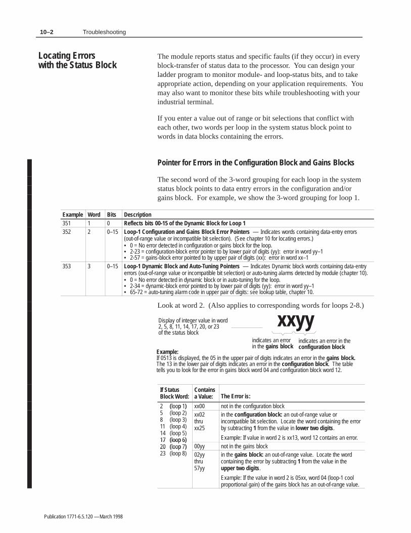
10–2 Troubleshooting
Publication 1771-6.5.120 — March 1998
The module reports status and specific faults (if they occur) in everyblock-transfer of status data to the processor. You can design yourladder program to monitor module- and loop-status bits, and to takeappropriate action, depending on your application requirements. Youmay also want to monitor these bits while troubleshooting with yourindustrial terminal.
If you enter a value out of range or bit selections that conflict witheach other, two words per loop in the system status block point towords in data blocks containing the errors.
Pointer for Errors in the Configuration Block and Gains Blocks
The second word of the 3-word grouping for each loop in the systemstatus block points to data entry errors in the configuration and/orgains block. For example, we show the 3-word grouping for loop 1.
Example Word Bits Description351 1 0 Reflects bits 00-15 of the Dynamic Block for Loop 1352 2 0–15 Loop-1 Configuration and Gains Block Error Pointers — Indicates words containing data-entry errors
(out-of-range value or incompatible bit selection). (See chapter 10 for locating errors.)• 0 = No error detected in configuration or gains block for the loop.• 2-23 = configuration-block error pointer to by lower pair of digits (yy): error in word yy–1• 2-57 = gains-block error pointed to by upper pair of digits (xx): error in word xx–1
353 3 0–15 Loop-1 Dynamic Block and Auto-Tuning Pointers — Indicates Dynamic block words containing data-entryerrors (out-of-range value or incompatible bit selection) or auto-tuning alarms detected by module (chapter 10).• 0 = No error detected in dynamic block or in auto-tuning for the loop.• 2-34 = dynamic-block error pointed to by lower pair of digits (yy): error in word yy–1• 65-72 = auto-tuning alarm code in upper pair of digits: see lookup table, chapter 10.
Look at word 2. (Also applies to corresponding words for loops 2-8.)
Display of integer value in word 2, 5, 8, 11, 14, 17, 20, or 23 of the status block
indicates an error in the gains block
indicates an error in theconfiguration block
Example: If 0513 is displayed, the 05 in the upper pair of digits indicates an error in the gains block.The 13 in the lower pair of digits indicates an error in the configuration block. The tabletells you to look for the error in gains block word 04 and configuration block word 12.
xxyy
If Status Block Word:
Containsa Value: The Error is:
2 (loop 1)5 loo 2
xx00 not in the configuration block2 (loop 1)5 (loop 2)8 (loop 3)11 (loop 4)14 (loop 5)17 (loop 6)
xx02 thru xx25
in the configuration block: an out-of-range value orincompatible bit selection. Locate the word containing the errorby subtracting 1 from the value in lower two digits.
Example: If value in word 2 is xx13, word 12 contains an error.17 (loop 6)20 (loop 7)2 loo 8
00yy not in the gains block20 (loop 7)23 (loop 8) 02yy
thru 57yy
in the gains block: an out-of-range value. Locate the wordcontaining the error by subtracting 1 from the value in theupper two digits.
Example: If the value in word 2 is 05xx, word 04 (loop-1 coolproportional gain) of the gains block has an out-of-range value.
Locating Errors with the Status Block

10–3Troubleshooting
Publication 1771-6.5.120 — March 1998
Pointer for Dynamic-Block Errors and Auto-Tuning Alarms
Look at word 3. (Also applies to corresponding words for loops 2-8.)
The third word of the 3-word grouping for each loop in the systemstatus block points to your data entry errors in the dynamic-blockand/or auto-tuning alarms detected by the module.
Display of integer value in word 3, 6, 9, 12, 15, 18, 21, or 24 of the status block
indicates an alarm in theauto-tuning process
indicates an error in thedynamic block
Example: If 6724 is displayed, the 67 in the upper pair of digits indicates an alarm in auto-tuning,and the 24 in the lower pair of digits indicates a data entry error in the dynamic block.The table tells you the meaning of auto-tuning alarm code 67, and to look for a dataentry error in dynamic block word 23.
xxyy
If Status Block Word:
Containsa Value: The Error is:
3 (loop 1)6 loo 2
xx00 not in the dynamic block3 (loop 1)6 (loop 2)9 (loop 3)12 (loop 4)15 (loop 5)18 (loop 6)
xx02 thru xx34
in the dynamic block: an out-of-range value or incompatible bitselection. Locate the word containing the error by subtracting 1from the value in the lower two digits.
Example: If value in word 3 is xx24, word 23 contains an error.18 (loop 6)21 (loop 7)2 loo 8
00yy not in auto-tuning the loop.21 (loop 7)24 (loop 8) Use the following table for module-detected auto-tuning alarms:2 loo 8
65yy Auto-tuning terminated because of thermal runaway.66yy Auto-tuning terminated because of thermocouple break.67yy Heat auto-tuning is inhibited because of the starting conditions.68yy Cool auto-tuning is inhibited because of the starting conditions.69yy Set point will be reached before auto-tuning is complete.70yy Too much noise causing time constant to be 0.71yy Very small gain.72yy Set point exceeded before auto-tuning completed.

10–4 Troubleshooting
Publication 1771-6.5.120 — March 1998
Notes:

Publication 1771-6.5.120 — March 1998
Number of PID Loops 8 individually isolatedI/O Chassis Location any single I/O module slotA/D Resolution 16 bits or 15 bits plus sign bitInput Filtering 6-pole low-pass hardware filterCalibration Interval 6 months, then yearly
Isolation Voltage
Designed to withstand 1000V dc continuous between inputchannels and between input and backplane connections.Modules are 100% tested at 1200V dc for 1 secondbetween input channels and backplane connections.
Backplane Current Load• steady-state maximum• surge at power turn-on
1771-TCM 1771-TCMR• 1.1A (1.0A for series B) 1.2A• 1.5A (1.0A for series B) 1.5A
Environmental Conditions• Operating Temperature• Rate of Change
• Storage Temperature• Relative Humidity
• 0 to 60oC (32 to 140oF)• Ambient changes greater than 0.5oC/minute may
degrade performance during periods of change.• –40 to 85oC (–40 to 185oF)• 5 to 95% (without condensation)
Connecting Cable(s) 1771-NC6 = 1.8m (6 ft)1771-NC15 = 4.6m (15 ft)
Keying Between 26 and 28 Between 32 and 34
Weight 0.8 kg (1.8 lb)Agency Certification(when product orpackaging is marked)
• CSA Class I, Division 2 Hazardous• UL listed• CE marked for all applicable directives (series C only)
Default Display Resolution 0.1°C (0.1°F)Temperature Scale °C (°F)Input Impedance > 10 MΩOpen Input Detection upscaleTime to Detect Open Input 5s (maximum)Input OvervoltageProtection 140V ac rms continuous
Normal Mode Rejection(50/60Hz) 50dB / 60dB (minimum)
Common Mode Rejection(60Hz) 150dB (typical)
Input Bandwidth 9HzUpdate Time (8 loops) 1sTPO Update Time(block-transfer) 100ms (typical) — 500ms (maximum)
TPO Update Time forheat/cool (single-transfer) 20ms (maximum)
TPO Update Time for heatonly (single-transfer) 10ms (maximum)
Settling Time to within0.1% Full Scale 125ms (maximum)
Non-linearity 0.02% of full range (maximum)
General Specifications

SpecificationsA–2
Publication 1771-6.5.120 — March 1998
Temperature Specifications (1771-TCM)Input Range
ctMillivolt: ±105mVInput Range
(selectable) Thermocouple (TC)Type B: 300 to 1800oC (572 to 3272oF)Type E: –270 to 1000oC (–454 to 1832oF)Type J: –210 to 1200oC (–346 to 2192oF)Type K: –270 to 1372oC (–454 to 2502oF)Type R: –50 to 1768oC (–58 to 3214oF)Type S: –50 to 1768oC (–58 to 3214oF)Type T: –270 to 400oC (–454 to 752oF)
Maximum Input Resolution 3.3µV/bit @ 15 bits with sign bitType E, J, K, T 0.1°C (0.2°F)
Type B, R, S: 0.3oC (0.6oF)
Thermocouple Linearization IPTS-68 standard, NBS MN-125
Cold Junction Compensation 0 to 70°C ±0.25°C
Open TC Leakage Current < 10 nA (maximum)
Offset Drift (maximum) ±0.50µV/°C
Gain Drift (maximum) ±35ppm/°C
Accuracy with Calibration (includes non-linearity, gain, offset)
0.01% of full range @ 25°C (typical)0.05% of full range @ 25°C (maximum)
Calibration Values 0.000 / 100.000mV
Underrange Threshold –103.0mV
Overrange Threshold +103.0mV
Rate Alarm Value Minimum (0.04% FSR)Maximum (50% FSR)
0.08mV / 0.9°C (1.6°F) per second100mV / 1050°C (1890°F) per second
Scaling Points → Default Scaling Values
–100/+100mV → –100.00/+100.00–300/+1800°C → –300.0/1800.0–508/+3272°F → –508.0/3272.0
Maximum resolution is obtained by rescaling input data to counts. These resolutions apply to the commonly used ranges for these thermocouples. See graphs.
Temperature Specifications (1771-TCMR)Input Range (selectable)
Resistance Type (RTD)100 ohm platinum (Euro) –200 to +870oC (–328 to +1598oF100 ohm platinum (USA) –200 to +630oC (–328 to +1166oF120 ohm Nickel –80 to +320oC (–112 to + 608oF10 ohm copper –200 to + 260oC (–328 to +500oF
Maximum Input Resolution 10mΩ/bit@16 bits unipolar100ΩPt & 120ΩNi 0.03oC(0.06oF)10Ω Cu 0.3oC (0.5oF)
RTD excitation current 1mA (typical)
Offset Drift (maximum) ±25m/°C
Gain Drift (maximum) ±50ppm/°C
Accuracy with Calibration (includes non-linearity, gain, offset)
0.025% of full range @ 25°C (typical)0.05% of full range @ 25°C (maximum)
Calibration Values 1.00 / 649.0
Underrange Threshold 0.9
Overrange Threshold 650

Specifications A–3
Publication 1771-6.5.120 — March 1998
Rate Alarm Value Minimum (0.04% FSR)Maximum (50% FSR)
0.26 / 0.44°C (0.8°F) per second325 / 550°C (990°F) per second
Scaling Points → Default Scaling Values
+1/650 → 10/6500–200/900°C → –2000/9000–328/1652°F → –3280/16520
Res
olut
ion
( C
/bit)
0.00
0.05
0.10
0.15
0.20
0.25
0.30
0.35
0.40
0.45
0.50
0.55
0.60
–200 0 200 400 600 800 1000 1200 1400 1600 18000.00
0.05
0.10
0.15
0.20
0.25
0.30
0.35
0.40
0.45
0.50
0.55
0.60
–200 0 200 400 600 800 1000 1200 1400 1600 18000.00
0.05
0.10
0.15
0.20
0.25
0.30
0.35
0.40
0.45
0.50
0.55
0.60
–200 0 200 400 600 800 1000 1200 1400 1600 18000.00
0.05
0.10
0.15
0.20
0.25
0.30
0.35
0.40
0.45
0.50
0.55
0.60
–200 0 200 400 600 800 1000 1200 1400 1600 1800
Temperature (°C)
0.0
0.1
0.2
0.3
0.4
0.5
0.6
0.7
0.8
–328 32 392 752 1112 1472 1832 2192 2552 2912 32720.0
0.1
0.2
0.3
0.4
0.5
0.6
0.7
0.8
–328 32 392 752 1112 1472 1832 2192 2552 2912 32720.0
0.1
0.2
0.3
0.4
0.5
0.6
0.7
0.8
–328 32 392 752 1112 1472 1832 2192 2552 2912 32720.0
0.1
0.2
0.3
0.4
0.5
0.6
0.7
0.8
–328 32 392 752 1112 1472 1832 2192 2552 2912 32720.0
0.1
0.2
0.3
0.4
0.5
0.6
0.7
0.8
–328 32 392 752 1112 1472 1832 2192 2552 2912 3272
Temperature (°F)
Res
olut
ion
( F/
bit)
°
°
JB S TKR E
Thermocouple
Thermocouple Characteristics

SpecificationsA–4
Publication 1771-6.5.120 — March 1998
Notes:

Publication 1771-6.5.120 — March 1998
This appendix lists the module’s power-up default parameters stored inthe module before any communication occurrs (prior to downloadingconfiguration, gains, or dynamic blocks.) You may want to test themodule in the default configuration before you configure it for yourapplication. In default configuration, you can only monitor loops byreading the status block.
For the Configuration Block
Parameter: Default Value: (bit = 0)
TC Break Detection Configuration Disable PID loop (M = 0)Thermal Runaway Configuration Disable PID loop (M = 0)Loop Operational Mode Monitor modeThermocouple Type JControl Action E = SP–COutput Ramping Disable rampingAlarm Enable Suppress all alarmsAuto-Tuning System Response MediumZone Select Inner zoneBarrel/Non-barrel Control Barrel controlInput Filter Enable Disable FilterSetpoint Ramp Rate 0.00o/minHigh Output Limit 100.00%Low Output Limit 0.00%Forced Output Value on TC Break 0.00%Forced Output Value on Thermal Runaway 0.00%Heat Minimum On Time 0.00sHeat TPO Period 5sCool Minimum On Time 0.00sCool TPO Period 5sAuto-tune Startup Aggressiveness 0Input Temperature Alarm Rate DisabledLow temperature Alarm Value 0.0°High Temperature Alarm Value 3276.7°Low Deviation Alarm Value 3276.7°High Deviation Alarm Value 3276.7°Temperature Alarm Dead Band 0.0°Thermal Runaway Temperature Change Value 5°Thermal Runaway Period 20 minutesRTD Type 000 ohmsNon-barrel Auto-tune Disturbance Size 0.00Time Constant for Input Filter 0.0

Default Parameter ValuesB–2
Publication 1771-6.5.120 — March 1998
For the Gains Block
Parameter: Default Value:
Proportional Gain 0.00Integral Gain 0.0000Derivative Gain 0.0
For the Dynamic Block
Parameter: Default Value: (bit = 0)
Loop Enable/Disable DisabledLoop Auto/Manual Mode Select ManualLoop Auto-tune Enable/disable DisableLoop Setpoint Ramp-hold Enable/Disable DisableRead-block Select Returns System StatusCold-junction Alarm Enable DisableCelsius/Fahrenheit Select Fahrenheit (Bit = 1)Integer Display Mode Enable Disable

Publication 1771-6.5.120 — March 1998
This program is on disk with TemperatureControl configurationsoftware that came with the module. Use it to test the module or as amodel to develop your own application program. It has two versions:
For processor-module communcation: Use this file:
in a local system or on a remote I/O link with 1771-ASB I/O adapter TCMRIO.AF5on ControlNet link with 1771-ACN I/O adapter TCMNET.AF5
Important: If using Pro-Set 700 software, do not use this program.Pro-Set 700 software includes its own for interfacing with the module.
This program is also available from the Allen-Bradley SupportPlusbulletin board by calling (216) 646-6728. Look for TCMRIO.ZIP orTCMNET.ZIP located in the PLC-5 section of the control-processorfile area under 6200 Arch Files. You can download this archive fileby copying it and, if necessary, renaming it.
This program is assigned to program file 2. This file was selectedbecause it is the default main control program (MCP), which willassure that it is executed every program scan. If you place thisprogram in another program file, you must ensure its execution iswithin the time base required.
If you have an existing application program, you can add this to it.Take special care to assign data table addresses correctly to ensurethere is no conflict between your program and what you add. If youinstall multiple temperature control modules in your PLC system, youwill need to assign a separate integer file for each of them. Only onemodule can use file N7. You will have to make the correspondingaddress changes for each additional module.
This program uses the following data table files.
File: Used For: Minimum File Size
O:00 Output file Fixed by PLC typeI:00 Input file Fixed by PLC typeS2:0 Status file Fixed at 129 wordsT4:0 Timer file 1 timer structureN7:0 Integer file 613 integer wordsBT9:0, BT9:1 Block-transfer control files 2 BT control structures
O:00
O:277
N7:0
N7:613
I:00
I:277
S2:0
S2:128
T4:0 BT9:0BT9:1
The Ladder Program
Program File
Data-Table Files

Communication ProgramC–2
Publication 1771-6.5.120 — March 1998
Data-Table Files O and I
The module has the capability of both single-transferring and block-transferring control data to/from the PLC data table. This exampleshows the use of both block-transferred and single-transferred TPOsignals. Typically there is no need to use the single-transferred TPOsignals (in the I/O image files) unless your application requires veryprecise turn-on/turn-off times (typically 10ms). Most applicationscan easily be controlled by the block-transferred TPO signals (typically 100ms). In this example, the module is in I/O group 1 of I/O rack 0and digital output modules for TPO signals are in I/O groups 2 and 3.
File Word Description
O 0O1 TCM or TCMR module2 Digital output module to control heating elements3 Digital output module to control cooling elements
I 0I1 TCM or TCMR module
The addressing in this example is based on 1-slot addressing with thefollowing hardware configuration.
PLC
-5 P
roce
ssor
1771
-TC
M o
r -TC
MR
1771
-OA
1771
-OA
RTP1orRTP4
I/O Rack 0 I/O Module Slot 0 54321 76
1-Slot Addressing
ÍÍÍÍ
ÍÍ
Í
Í
ÍÍÍÍ
ÍÍ
ÍÍÍÍ
ÍÍ
Í
Í
Í
Í
ÍÍÍÍ
ÍÍ
Dig
ital o
utpu
ts to
hea
ting
elem
ents
Dig
ital o
utpu
ts to
coo
ling
valv
es
Inputs from temperaturesensors
HnH1 H2 H3
Nozzle Zone 1 Zone 2 Zone 3
Ts Tn T1 T2 T3 Tf
T = temperature measurement point H = heater band (element)
Typical plastic injection barrelwith multiple temperature zones
Ram(Screw)

Communication Program C–3
Publication 1771-6.5.120 — March 1998
Data-Table File 7 (N) Integer
To simplify the interface, we established a 615 word integer file (N7)exclusively for the module. All information concerning that moduleis contained in this file. The specific data layout is as follows:
File Word Description
N7 0 Communication control word (initiates block-transfer of configuration,auto-tune, or gains values when you set a specific bit) (See page C–4)
1 BT ID bits2 BT check mask3 Cycle sequence number4 Loop offset value5 Data-table file offset6 reserved7 reserved8 reserved9 TPO bits — single-transferred10 – 39 Loop-1 configuration data40 – 69 Loop-2 configuration data70 – 99 Loop-3 configuration data100 – 129 Loop-4 configuration data130 – 159 Loop-5 configuration data160 – 189 Loop-6 configuration data190 – 219 Loop-7 configuration data220 – 249 Loop-8 configuration data250 – 309 Gains block310 – 349 Dynamic block350 – 419 Status block420 – 479 Auto-tune block480 – 549 Scratch-pad area addressed by the block-transfer write instruction550 – 613 Scratch-pad area addressed by the block-transfer read instruction
Data-Table File 9 (BT) Block Transfer
This file contains the block-transfer control structures forcommunication with the module. The block-transfer write controlstructure is BT9:0. The block-transfer read control structure is BT:9:1.
This program uses a data-table layout which has been organized toprovide a convenient interface for these bits and words:
• communication control bits
• single-transferred TPO bits
• block-transferred TPO bits
• temperature monitor words
• loop output words
• current setpoint words
Data-Table InterfaceLayout

Communication ProgramC–4
Publication 1771-6.5.120 — March 1998
Communication Control Bits
By one-shot latching any one of bits 0-11 of N7:0, you initiate acorresponding block-transfer. Bits 14 and 15, which are usedinternal to the program, can be monitored.
!ATTENTION: Communication control bits 8-11 forrequesting a gains block read or write, and an auto-tuneblock read or write have been changed since theoriginal version of this program. Check your version.
File Word Bit Description
N7 0 0 Loop-1 configuration block write to moduleN7 01 Loop-2 configuration block write to module2 Loop-3 configuration block write to module3 Loop-4 configuration block write to module4 Loop-5 configuration block write to module5 Loop-6 configuration block write to module6 Loop-7 configuration block write to module7 Loop-8 configuration block write to module8 Auto-tune block write to module9 Auto-tune block read from module10 Gains block write to module11 Gains block read from module12 reserved13 reserved14 Manual download requested. No BT in progress (monitor only)15 Block-transfer to/from module in progress (monitor only)
0123456789101112131415
Loop
1
Loop
2
Loop
3
Loop
4
Loop
5
Loop
6
Loop
7
Loop
8
Write configuration block
Write gains blockRead gains block
Write auto-tune blockRead auto-tune block
WordN7:0
Initiate a block-transfer with oneof these 12 communicationcontrol bits
Do not control thesetwo bits with your ladderlogic outside of thisexample program
Single-Transferred TPO Bits
Output control (TPO) bit values are single-transferred from the moduleto the input image table in TPO form. You can use these bits to controldigital outputs driving heating and cooling elements. For heat-only orcool-only operation, the effective period for the module updating theheat or cool TPO bits is approximately 10ms. However, if you useboth heating and cooling, the effective period for updating the TPObits is about 20ms. If you use the TPO signals block-transferred fromthe module, you do not need to read these bits.

Communication Program C–5
Publication 1771-6.5.120 — March 1998
File Word Bit Description
N7 9 0 Loop-1 Heat TPO Bit — Single-TransferredN7 9
1 Loop-2 Heat TPO Bit — Single-Transferred
2 Loop-3 Heat TPO Bit — Single-Transferred
3 Loop-4 Heat TPO Bit — Single-Transferred
4 Loop-5 Heat TPO Bit — Single-Transferred
5 Loop-6 Heat TPO Bit — Single-Transferred
6 Loop-7 Heat TPO Bit — Single-Transferred
7 Loop-8 Heat TPO Bit — Single-Transferred
8 Loop-1 Cool TPO Bit — Single-Transferred
9 Loop-2 Cool TPO Bit — Single-Transferred
10 Loop-3 Cool TPO Bit — Single-Transferred
11 Loop-4 Cool TPO Bit — Single-Transferred
12 Loop-5 Cool TPO Bit — Single-Transferred
13 Loop-6 Cool TPO Bit — Single-Transferred
14 Loop-7 Cool TPO Bit — Single-Transferred
15 Loop-8 Cool TPO Bit — Single-Transferred
Block-Transferred TPO Bits
Output control (TPO) bit values are block-transferred from the modulein TPO form. You can use these bits to control digital outputs drivingheating and cooling elements. The module’s period for updating theheat and cool TPO bits it makes available by block-transfer is about100ms. If you use TPO signals single-transferred to the input imagetable, you do not need to read these bits.
File Word Bit Description
N7 375 0 Loop-1 Heat TPO Bit — Block-TransferredN7 3751 Loop-2 Heat TPO Bit — Block-Transferred2 Loop-3 Heat TPO Bit — Block-Transferred3 Loop-4 Heat TPO Bit — Block-Transferred4 Loop-5 Heat TPO Bit — Block-Transferred5 Loop-6 Heat TPO Bit — Block-Transferred6 Loop-7 Heat TPO Bit — Block-Transferred7 Loop-8 Heat TPO Bit — Block-Transferred8 Loop-1 Cool TPO Bit — Block-Transferred9 Loop-2 Cool TPO Bit — Block-Transferred10 Loop-3 Cool TPO Bit — Block-Transferred11 Loop-4 Cool TPO Bit — Block-Transferred12 Loop-5 Cool TPO Bit — Block-Transferred13 Loop-6 Cool TPO Bit — Block-Transferred14 Loop-7 Cool TPO Bit — Block-Transferred15 Loop-8 Cool TPO Bit — Block-Transferred

Communication ProgramC–6
Publication 1771-6.5.120 — March 1998
Temperature Monitor Words
These words contain the input temperature value for each loop. Thesevalues are in °C or °F as you select in the module configuration.
File Word Bit Description
N7 376 0–15 Loop-1 input temperature in degreesN7377 0–15 Loop-2 input temperature in degrees378 0–15 Loop-3 input temperature in degrees379 0–15 Loop-4 input temperature in degrees380 0–15 Loop-5 input temperature in degrees381 0–15 Loop-6 input temperature in degrees382 0–15 Loop-7 input temperature in degrees383 0–15 Loop-8 input temperature in degrees
Loop Output Words
These output control words contain the loop output (as % of output)block-transferred from the module in numeric-value form. You canuse these words to control analog outputs driving heating and coolingelements or you can monitor them from your man-machine interface.
File Word Bit Description
N7 384 0–15 Loop-1 output in % (heat/cool –100.00% thru +100.00%)N7
385 0–15 Loop-2 output in % (heat/cool –100.00% thru +100.00%)
386 0–15 Loop-3 output in % (heat/cool –100.00% thru +100.00%)
387 0–15 Loop-4 output in % (heat/cool –100.00% thru +100.00%)
388 0–15 Loop-5 output in % (heat/cool –100.00% thru +100.00%)
389 0–15 Loop-6 output in % (heat/cool –100.00% thru +100.00%)
390 0–15 Loop-7 output in % (heat/cool –100.00% thru +100.00%)
391 0–15 Loop-8 output in % (heat/cool –100.00% thru +100.00%)
Current Setpoint Words
These words contain the current setpoint values block-transferred fromthe module. This value reflects ramping if ramping is selected andvalidates the actual setpoint to which the loop is being controlled.
File Word Bit Description
N7 392 0–15 Loop-1 current setpoint value — (0 thru +999.9°)N7393 0–15 Loop-2 current setpoint value — (0 thru +999.9°)394 0–15 Loop-3 current setpoint value — (0 thru +999.9°)395 0–15 Loop-4 current setpoint value — (0 thru +999.9°)396 0–15 Loop-5 current setpoint value — (0 thru +999.9°)397 0–15 Loop-6 current setpoint value — (0 thru +999.9°)398 0–15 Loop-7 current setpoint value — (0 thru +999.9°)399 0–15 Loop-8 current setpoint value — (0 thru +999.9°)

Communication Program C–7
Publication 1771-6.5.120 — March 1998
This ladder logic is written for a PLC configuration of:
• 1-slot addressing
• the module in I/O slot 1
• 1771-OA module for controlling heating elements in I/O slot 2
• 1771-OA module for controlling cooling elements in I/O slot 3
• pushbutton switch for manually re-starting the single-transfersequence is connected to input I:004/7.
If your configuration is different, change the addresses as follows:
• In the block-transfer write instructions on rungs 5 and 6, enter therack, group, and module slot to identify the module’s location address.
• In the block-transfer read instruction on rung 7, enter the rack,group, and module slot to identify the module’s location address.
• On rungs 9-13, replace each O:001 address to reflect the locationof the module.
• On rung 9, change the I:004/07 address to reflect the location ofthe connection to the pushbutton switch for manually starting thesingle-transfer sequence.
!ATTENTION: This program does not provide aninterlock for TPO outputs. If your application requiresthese outputs to be held off for some reason separatefrom the module, or in the case of the module losingcommunication, add your own logic to provide theappropriate output signal for your application.
To configure the module for your application, manipulate the datatable values as follows:
1. Set the bits in data-table words N7:10 thru N7:249 to configureeach loop as required for your application (see page C-3 andchapter 4 for details).
2. You can also enter PID gains/constants in words N7:250 thruN7:309 (see chapter 6). However, if you are going to useauto-tuning, you don’t need to enter anything there.
3. Set the bits (0-7) in the communication control word N7:0 toinitiate a block-transfer write to the module. This loads theconfiguration values for each loop. If the module looses power,you will have to reload configuration values into the module.
You can monitor and set values in these data table files with anyonline programming or MMI (such as PanelView or a PC withControlView software) that can access PLC data tables.
Establish the ModuleInterface for YourApplication
Configure the ControlLoops

Communication ProgramC–8
Publication 1771-6.5.120 — March 1998
Once the loops that are to be used are configured, you can start upand auto-tune the loops with the following procedure. The specificexample addresses given are for loop 1 for this example program.
1. Set the loop operational mode to control mode for the loop(s):configuration block, word 1, bits 7–8 (N7:11/7, N7:11/8)
2. Set manual output value for the loop(s) to current steady-state output: dynamic block, word 4 (N7:314)
3. Set the loop(s) to manual control mode:dynamic block, word 1, bit 1 (N7:311/1)
4. Enable loop control for the loop(s):dynamic block, word 1, bit 0 (N7:311/0)
5. Enter the run-temperature set-point value:dynamic block, word 1 (N7:313)
6. Select the run-temperature set point:dynamic block, word 1, bit 2 (N7:311/2)
7. Select to enable auto-tuning:dynamic block, word 1, bit 3 (N7:311/3). This begins the auto-tuning and start-up cycle.
8. Turn on the invoke-auto-tuning bit:dynamic block, word 43, bit 1 (N7:343/1). This starts the auto-tuning and start-up cycle.
9. Once auto-tuning has begun, set the loop to automatic control mode:dynamic block, word 1, bit 1 (N7:311/1). This will then return theloop to auto control once the auto-tune and start-up are complete.
Important: Auto-tuning has been optimized for tuning multipleloops for plastic injection molding and extruder barrels.The concept is to start-up a process from ambient andtune the loops as the system is starting up.
The communication program was developed to assist you in applyingthe module. This program provides the basic logic to:
• communicate with the module
• load loop configuration data when requested
• provide an interactive interface for the dynamic information
• provide continuous monitoring of the module status data
• load or read PID parameter data when requested
Start Up and Auto-TuneLoops Set for BarrelControl
Basic Operation of theCommunication Program

Communication Program C–9
Publication 1771-6.5.120 — March 1998
1771
-OA
Mod
ule
Cool TPODataTable
Block-Transfer Write
Block-Transfer Read
Mod
ule
1771
-OA
Mod
ule
Heat TPO
MMI6200Software
To accomplish this, communication with the module is established by:
• continuously requesting block-transfers at 250ms intervals in thefollowing sequence:
1. write dynamic block which provides a control interface withthe module (selecting to read the status block)
2. read status block which provides data such as loop andmodule status, and M and C values
This will update all run-time information to and from the modulein one module (loop) update period of 500ms. However, if youhave a requirement to continually monitor the gains block, thenyou could have the dynamic block alternate between requesting astatus block and requesting a gains block. In this case, you couldonly read the status block once every second.
• writing a loop configuration block and reading or writing thegains block or auto-tune block to/from the module on demand asa priority request in place of the dynamic block.
To request this block transfer: Set this bit:
write loop configuration appropriate bit in communication control word (N7:0).Bits 0-7 correspond to loops 1-8 configuration blocks.
read gains block N7:0/11
write gains block N7:0/10
read auto-tune N7:0/9
write auto-tune N7:0/8
Multiple simultaneous requests are allowed. To configure all loops,write 00FF16 to N7:0 (set bits 0-7). The requests are servicedsequentially with priority over dynamic-block writes.
When a block-transfer write is completed as requested, the correspondingrequest is cleared by the program. When a request for a block-transferwrite results in an error or no response, the request is re-queued. Thisre-queuing will continue until that request is successfully serviced.Re-queuing does not impede other requests.

Communication ProgramC–10
Publication 1771-6.5.120 — March 1998
This rung ensures that the program is reset and ready to run. When thePLC processor is powered up, bit S:1/15 is turned on for only the firstprogram scan. This bit being on is used to reset initialization values.
• Word N7:2, the loop check mask, is set to 1.
• Word N7:3, the cycle sequence number, is set to 1.
• Word N7:4, the loop offset value is set to 0.
• The proper block ID is put into the first word of each block(words N7:10, N7:40, N7:70, N7:130, N7:160, N7:190, N7:220,N7:250, and N7:310).
Rung 2:0/ // // /| S:1 +MOV–––––––––––––––+ |+––] [––––––––––––––––––––––––––––––––––––––––––––––––––++MOVE ++–+| 15 ||Source 1|| || || || || ||Destination N7:2|| || || 1|| || |+––––––––––––––––––+| || | N7:3| || +––––––––––––––––(L)–+ || | 0| || |+CLR–––––––––––––––+| || ++CLEAR ++ || ||Destination N7:4|| || || 0|| || |+––––––––––––––––––+| || |+MOV–––––––––––––––+| || ++MOVE ++ || ||Source –30719|| || || || |/ // // /
/ // // /| ||Source –30714|| || || || || ||Destination N7:160|| || || –30714|| || |+––––––––––––––––––+| || |+MOV–––––––––––––––+| || ++MOVE ++ || ||Source –30713|| || || || || ||Destination N7:190|| || || –30713|| || |+––––––––––––––––––+| || |+MOV–––––––––––––––+| || ++MOVE ++ || ||Source –30712|| || || || || ||Destination N7:220|| || || –30712|| || |+––––––––––––––––––+| || |+MOV–––––––––––––––+| || ++MOVE ++ || ||Source –30711|| || || || || ||Destination N7:250|| || || –30711|| || |+––––––––––––––––––+| || |+MOV–––––––––––––––+| || ++MOVE ++ || ||Source –30710|| || || || || ||Destination N7:310|| || || –30710|| || |+––––––––––––––––––+| |/ // /
Rung 2:0 Initialization

Communication Program C–11
Publication 1771-6.5.120 — March 1998
| | N7:0 | || +–––––––––––––––(U)––+ || | 15 | || | N7:343| || +–––––––––––––––(U)––+ || | 0 | || | N7:343| || +–––––––––––––––(U)––+ || | 6 | || |+MOV–––––––––––––––+| || ++MOVE ++ || ||Source 0|| || || || || ||Destination N7:9|| || || || || |+––––––––––––––––––+| || |+MOV–––––––––––––––+| || ++MOVE ++ || ||Source 0|| || || || || ||Destination N7:375|| || || || || |+––––––––––––––––––+| || Important : If not using TemperatureControl |+MOV–––––––––––––––+| || Connfig Software included with the module, ++MOVE ++ || you may want to delete this instruction or >> ||Source 511 || || change Source from 511 to 255 so as NOT to, || || || clear the gains block on first scan. ||Destination N7:0|| || || || || |+––––––––––––––––––+| |
If there are no manual downloads (loop configuration or tuning data)required, the program automatically sequences thru a pair of presettransfers of data blocks.
1. Write the dynamic block to the module.
2. Read the status block (loop I/O signals, alarms) from the module.
The sequence number, which dictates which block-transfer toexecute, is toggled every 250ms thru the exclusive or instruction.
Rung 2:1| T4:0 +TON–––––––––––––––+ |+––]/[–––––––––––––––––––––––––––––––––––––––––––––––––––––––––––––––––––––––+TIMER ON DELAY +–(EN)–+| DN |Timer T4:0| || |Time base 0.01+–(DN) || |Preset 25| || |Accum 3| || +––––––––––––––––––+ |Rung 2:2| T4:0 +XOR–––––––––––––––––––––––––+ |+––] [––––––––––––––––––––––––––––––––––––––––––––––––––––––––––––––––––+BITWISE EXCLUSIVE OR +–+| DN |Source A N7:3| || | 0| || |Source B 0000000000000001| || | | || |Destination N7:3| || | 0| || +––––––––––––––––––––––––––––+ |
Rung 2:1 and 2:2 250ms Time Base forAutomatic Block-Transfer

Communication ProgramC–12
Publication 1771-6.5.120 — March 1998
Before responding to the automatic block-transfers, a check is made todetermine whether a block-transfer has been manually requested (N7:0,bits 1 thru 11) by an NEQ instruction (N7:0 0). If a bit has beenturned on, then this rung will filter the request to ensure that only bits1-11 have been turned on, then begin the process of establishing whichbit has been turned on so that only the corresponding block of data istransferred to/from the module.
This rung (together with rung 2:4) detects a loop (1-8) configurationrequest, and then calculates the data-table file offset.
A bit-wise AND is used to determine which loop has its manual requestbit set. A bit in word N7:1 gets turned on only if the corresponding bitin N7:0 and the corresponding bit in N7:2 are turned on.
If N7:0 > 0, the bits in N7:2 are turned on one at a time, starting at bit 0 and proceeding to bit 11, until a match is found; then all are zeroed. (Bycounting the number of tests, the loop number is determined for transferringa configuration block.) By using a bit-wise AND (N7:0/x AND N7:2/y) thecorresponding bit is set in word N7:1. When N7:1 > 0, testing is stopped.
If the value at N7:1 is less than 256, (meaning a configuration blockrequest — bits 0-7) the following offset calculation is performed toestablish the starting word for the loop’s configuration file.
1. Calculate the data set number (30 words/loop): N7:4 X 30 = N7:5
2. Add 10 to the data set number: N7:5 + 10 = N7:5
3. This result points to the word in file N7 that is the start ofconfiguration data for the loop. N7:5 is used as an indirectaddress in the copy instruction.
Downloading the PID gains block or auto-tune block occurs when bit10 is On (for PID gains block at N7:250) or bit 8 is On (for auto-tuneblock at N7:420). The block is copied into the block-transfer writescratchpad area starting at N7:480 for download to the module.
Rung 2:3 Manual Block-TransferRequest, Identification, andControl

Communication Program C–13
Publication 1771-6.5.120 — March 1998
Rung 2:3| +NEQ–––––––––––+ +EQU–––––––––––+ BT9:0 +AND–––––––––––––––––––––––––+ |+–+NOT EQUAL +–+EQUAL +––]/[–++BITWISE AND +–––––––––––––––––––––––––––––+–+| |Source A N7:0| |Source A N7:1| EN||Source A N7:0| | || | 0| | 0| || 0| | || |Source B 0| |Source B 0| ||Source B 1100111111111111| | || | | | | || | | || +––––––––––––––+ +––––––––––––––+ ||Destination N7:0| | || || 0| | || |+––––––––––––––––––––––––––––+ | || |+NEQ–––––––––––––––+ N7:0 | || ++NOT EQUAL +––(U)––––––––––––––––––––––––––––––––––+ || ||Source A N7:420| 8 | || || –30709| | || ||Source B –30709| | || || | | || |+––––––––––––––––––+ | || |+AND–––––––––––––––+ | || ++BITWISE AND +–––––––––––––––––––––––––––––––––––––––+ || ||Source A N7:0| | || || 0| | || ||Source B N7:2| | || || 2| | || ||Destination N7:1| | || || 0| | || |+––––––––––––––––––+ | || |+NEQ–––––––––––+ +LES–––––––––––+ +MUL–––––––––––––––+ | || ++NOT EQUAL +++LESS THAN +++MULTIPLY +–––+++ || ||Source A N7:1|||Source A N7:1|||Source A N7:4| ||| || || 0||| 0||| 1| ||| || ||Source B 0|||Source B 256|||Source B 30| ||| || || ||| ||| | ||| || |+––––––––––––––+|+––––––––––––––+||Destination N7:5| ||| || | | || 11| ||| || | | |+––––––––––––––––––+ ||| || | | |+ADD–––––––––––––––+ ||| || | | ++ADD +–––+|| || | | ||Source A N7:5| ||| || | | || 11| ||| || | | ||Source B 10| ||| || | | || | ||| || | | ||Destination N7:5| ||| || | | || 11| ||| || | | |+––––––––––––––––––+ ||| || | | |+COP––––––––––––––––––+||| || | | ++COPY FILE ++|| || | | |Source #N7[N7:5]| || || | | |Destination #N7:480| || || | | | Length 26 | || || | | +–––––––––––––––––––––+ || || | | N7:1 +COP––––––––––––––––––+ || || | +–] [–––––––––––––+COPY FILE +–+| || | | 10 |Source #N7:250| || || | | |Destination #N7:480| || || | | |Length 57| || || | | +–––––––––––––––––––––+ || || | | N7:1 N7:1 || || | +–] [–––+–––––––––––––(U)–––+–––––––––––––+| || | | 11 | 11 | || || | | | N7:343 N7:0 | || || | | +–––]/[–––+–––(U)–––+ || || | | 6 | 11 | || || | | | N7:343| || || | | +–––(L)–––+ || || | | 0 || || | | N7:1 +COP––––––––––––––––––+ || || | +–] [–––––––––––––+COPY FILE +–+| || | | 8 |Source #N7:420| || || | | |Destination #N7:480| || || | | |Length 56| || || | | +–––––––––––––––––––––+ || || | | N7:1 N7:1 || || | +–] [–––+–––––––––––––(U)–––+–––––––––––––+| || | 9 | 9 | | || | | N7:343 N7:0 | | || | +–––]/[–––+–––(U)–––+ | || | 0 | 9 | | || | | N7:343| | || | +–––(L)–––+ | || | N7:0 6 | || +–( )–––––––––––––––––––––––––––––––––––––––––––––––––––––––+ || 14 |

Communication ProgramC–14
Publication 1771-6.5.120 — March 1998
This rung is used in connection with rung 2:3 to increment the loopcheck mask. When rung 2:3 is actively testing for a loop, it turns onbit N7:0/14. This enables the logic on rung 4 that:
• by multiplying the value in the loop check mask (N7:2) by 2,shifts the single bit that is on in the loop check mask to the nexthigher bit position, starting at the 20 bit (bit 0) and shifting eachscan time until reaching the 29 bit (bit 9)
• by incrementing the value in N7:4 by 1 each time this logic isexecuted, accumulates the total number of iterations, to establishthe loop offset value
• when the BT check mask has been shifted up to bit 9, meaning allpossible loops have been scanned, resets the loop offset value (N7:4)to 0 and resets the loop check mask (N7:2) to 1 (bit 0 turned on)
Rung 2:4| N7:0 +MUL–––––––––––––––+ |+–] [–––––––––––––––––––––––––––––––––––––––––––––––––––––+––––––––––––––––––––––+MULTIPLY ++–+| 14 | |Source A N7:2|| || | | 2|| || | |Source B 2|| || | | || || | |Destination N7:2|| || | | 2|| || | +––––––––––––––––––+| || | +ADD–––––––––––––––+| || +––––––––––––––––––––––+ADD ++ || | |Source A N7:4|| || | | 1|| || | |Source B 1|| || | | || || | |Destination N7:4|| || | | 1|| || | +––––––––––––––––––+| || | N7:2 +MOV–––––––––––––––+ | || +–] [––––––––––––––––++MOVE +++ || | 12 ||Source 1||| || | || ||| || | ||Destination N7:2||| || | || 2||| || | |+––––––––––––––––––+|| || | |+MOV–––––––––––––––+|| || | ++MOVE ++| || | |Source 0| | || | | | | || | |Destination N7:4| | || | | 1| | || | +––––––––––––––––––+ | || | N7:0| || +––––––––––––––––––––––––––––––––––––––(U)–+ || 14 |
If no block-transfer writes are in progress (BT9:0/EN), the communicationsequence timer has timed out, and no manual configuration downloadrequest has been made, then the dynamic block is written to the module.The copy instruction causes the current data for the dynamic block to beloaded into the scratch-pad area for block-transfer writes. The block-transfer write instruction causes the current data in the scratch-pad area tobe written to the module.
Rung 2:4 Loop Configuration/Gain DataDownload Control Support
Rung 2:5 AutomaticDynamic-Block-Transfer Writes

Communication Program C–15
Publication 1771-6.5.120 — March 1998
Rung 2:5| BT9:0 T4:0 N7:3 +MEQ–––––––––––––––+ +COP––––––––––––––––––––+ |+––]/[–––] [–––]/[––+MASKED EQUAL +––––––––––––––––––––––––––––––+–––––+COPY FILE ++–+| EN DN 0 |Source N7:0| | |Source #N7:310|| || | 0| | |Destination #N7:480|| || |Mask F5FF| | |Length 34|| || | | | +–––––––––––––––––––––––+| || |Compare 0| |+BTW––––––––––––––––––––+ | || | | ++BLOCK TRANSFER WRITE +–(EN)+ || +––––––––––––––––––+ |Rack 00| || |Group 1+–(DN) || |Module 0| || |Control block BT9:0+–(ER) || |Data file N7:480| || |Length 0| || |Continuous N| || +–––––––––––––––––––––––+ |
If a manual request has been made, and the loop number has been established(and data loaded into the block-transfer write scratch-pad area in rung 2:3)the block-transfer write instruction is executed. This instruction is used togenerate all blocks transfers to the module (configuration, dynamic, andgains). Once the block-transfer write has been completed, the manual looprequest bit is cleared (XOR) and the loop identity bits (N7:1) are cleared.Upon detection of a block-transfer error or no response, this rung also clearsthe loop identity bits; however, since the manual request bit is not cleared,the logic is enabled to retry that request again until the bit is cleared.
Rung 2:6| +NEQ–––––––––––––––+ BT9:0 N7:0 +BTW––––––––––––––––––––+ |+–+NOT EQUAL +–––––––––––––––––––––––––––––––––––+–]/[–––]/[–++BLOCK TRANSFER WRITE +–(EN)++–+| |Source A N7:1| | EN 15||Rack 00| || || | 0| | ||Group 1+–(DN)|| || |Source B 0| | ||Module 0| || || | | | ||Control block BT9:0+–(ER)|| || +––––––––––––––––––+ | ||Data file N7:480| || || | ||Length 0| || || | ||Continuous N| || || | |+–––––––––––––––––––––––+ || || | | N7:0|| || | +––––––––––––––––––––––––––(L)–+| || | 15 | || | BT9:0 N7:0 | || ++–] [–++–––––––––––––––––––––––––––(U)–+–––+ || | ER|| 15| || |BT9:0||BT9:0 +XOR––––––––––––––––––––+| || +–] [–++–] [––+BITWISE EXCLUSIVE OR ++ || | NR|| DN |Source A N7:0|| || |BT9:0|| | 0|| || +–] [–+| |Source B N7:1|| || DN | | 0|| || | |Destination N7:0|| || | | 0|| || | +–––––––––––––––––––––––+| || | +CLR–––––––––––––––+| || +–––––––––––+CLEAR ++ || |Destination N7:1| || | 0| || +––––––––––––––––––+ |
If no block-transfer reads are in process (BT9:1/EN) and the sequencetimer has timed out, the current sequence number (N7:3) is checked to seewhether it is equal to 1. If true, a block-transfer read is executed that loadsthe data into the block-transfer read scratch-pad area (N7:550 thruN7:613). This instruction is for all blocks transferred from the module(status, gains, and auto-tuning).
Rung 2:6Manual-Request Block-Transfer Write Control
Rung 2:7Block-Transfer Read Control

Communication ProgramC–16
Publication 1771-6.5.120 — March 1998
Rung 2:7| T4:0 BT9:1 N7:3 +BTR––––––––––––––––––––+ |+––] [–––]/[–––] [––––––––––––––––––––––––––––––––––––––––––––––––––––––+BLOCK TRANSFER READ +–(EN)–+| DN EN 0 |Rack 00| || |Group 1+–(DN) || |Module 0| || |Control block BT9:1+–(ER) || |Data file N7:550| || |Length 0| || |Continuous N| || +–––––––––––––––––––––––+ |
When the block-transfer read done bit (BT9:1) is on, the first word ofthe block-transfer read scratch-pad area is compared to the block IDcodes. The data is then copied to the appropriate block area based onthe block ID code detected.
• If the value is –30465, data returned is status, including TPO signals.
• If the value is –30711, data is the PID gains.
• If the value is –30709, data is the system ID data from auto-tuning.
Rung 2:8| BT9:1 +EQU–––––––––––––––+ +COP––––––––––––––––––––+ |+––] [–––––––––––––––––––––––––––––––––––––––––––––––++EQUAL +––+COPY FILE ++–+| DN ||Source A N7:550| |Source #N7:550|| || || –30465| |Destination #N7:350|| || ||Source B –30465| |Length 64|| || || | +–––––––––––––––––––––––+| || |+––––––––––––––––––+ | || |+EQU–––––––––––––––+ +COP––––––––––––––––––––+ | || ++EQUAL +++COPY FILE +++ || ||Source A N7:550|||Source #N7:550||| || || –30465|||Destination #N7:250||| || ||Source B –30711|||Length 57||| || || ||+–––––––––––––––––––––––+|| || |+––––––––––––––––––+| N7:343|| || | +––––––––––––––––––––(U)––+| || | 0 | || |+EQU–––––––––––––––+ +COP––––––––––––––––––––+ | || ++EQUAL +++COPY FILE +++ || |Source A N7:550|||Source #N7:550|| || | –30465|||Destination #N7:420|| || |Source B –30709|||Length 56|| || | ||+–––––––––––––––––––––––+| || +––––––––––––––––––+| N7:343| || +––––––––––––––––––––(U)––+ || 6 |
These rungs provide the logic for using TPO signals single-transferredfrom the module. Do not use these single-transferred TPO signals if themodule is in a remote I/O chassis. The logic of these rungs is explained indetail in chapter 3. However, there is a difference in addressing betweenthe rungs shown in chapter 3 and the rungs shown here. In chapter 3, heatTPO bits are written to an output module at O:002, and cool TPO bits arewritten to an output module at O:003. Here, heat TPO bits are written tothe low byte of N7:9, and cool TPO bits are written to the high byte ofN7:9. With this arrangement, in your application logic you can use eitherblock-transferred or single-transferred TPO bits to control outputs at anyaddress you want to use. In your output control logic, you should alsoprovide an interlock logic to hold these outputs in a safe state wheneverappropriate for your application
Rung 2:8Block-Transfer ReadData Distribution
Rungs 2:9 thru 2:13Single-Transfer TPO Interface

Communication Program C–17
Publication 1771-6.5.120 — March 1998
Rung 2:9| S:1 +BTD–––––––––––––––+ |+–+–] [–+–––––––––––––––––––––––––––––––––––––––––––––––––––––––––––––––––––––––––+BIT FIELD DISTRIB +–+| | 15| |Source 35| || |I:004| | | || +–] [–+ |Source bit 0| || 07 |Destination O:001| || | 8960| || |Destination bit 8| || |Length 8| || +––––––––––––––––––+ |Rung 2:10| +MEQ–––––––––––––––+ +BTD–––––––––––––––+ |+–+MASKED EQUAL +––––––––––––––––––––––––––––––––––––––––––––––––––––––––––++BIT FIELD DISTRIB ++–+| |Source I:001| ||Source I:001|| || | 0| || 0|| || |Mask 00FF| ||Source bit 8|| || | | ||Destination N7:9|| || |Compare 35| || 0|| || | | ||Destination bit 0|| || +––––––––––––––––––+ ||Length 8|| || |+––––––––––––––––––+| || |+BTD–––––––––––––––+| || ++BIT FIELD DISTRIB ++ || |Source 37| || | | || |Source bit 0| || |Destination O:001| || | 8960| || |Destination bit 8| || |Length 8| || +––––––––––––––––––+ |Rung 2:11| I:001 I:001 I:001 +BTD–––––––––––––––+ |+––]/[–––]/[–––]/[––––––––––––––––––––––––––––––––––––––––––––––––––––––––––––––––+BIT FIELD DISTRIB +–+| 07 06 00 |Source 0| || | | || |Source bit 0| || |Destination N7:9| || | 0| || |Destination bit 0| || |Length 8| || +––––––––––––––––––+ |Rung 2:12| +MEQ–––––––––––––––+ +BTD–––––––––––––––+ |+–+MASKED EQUAL +––––––––––––––––––––––––––––––––––––––––––––––––––––––––––++BIT FIELD DISTRIB ++–+| |Source I:001| ||Source I:001|| || | 0| || 0|| || |Mask 00FF| ||Source bit 8|| || | | ||Destination N7:9|| || |Compare 37| || 0|| || | | ||Destination bit 8|| || +––––––––––––––––––+ ||Length 8|| || |+––––––––––––––––––+| || |+BTD–––––––––––––––+| || ++BIT FIELD DISTRIB ++ || |Source 35| || | | || |Source bit 0| || |Destination O:001| || | 8960| || |Destination bit 8| || |Length 8| || +––––––––––––––––––+ |Rung 2:13| I:001 I:001 I:001 +BTD–––––––––––––––+ |+––]/[–––]/[–––]/[––––––––––––––––––––––––––––––––––––––––––––––––––––––––––––––––+BIT FIELD DISTRIB +–+| 07 06 00 |Source 0| || | | || |Source bit 0| || |Destination N7:9| || | 0| || |Destination bit 8| || |Length 8| || +––––––––––––––––––+ |Rung 2:14| |+––––––––––––––––––––––––––––––––––––––––––––––––––––––––[END OF FILE]–––––––––––––––––––––––––––––––––+| |

Communication ProgramC–18
Publication 1771-6.5.120 — March 1998
Notes:

Publication 1771-6.5.120 — March 1998
You select auto-tuning from the dynamic block. For each loop, youmust turn on the “auto-tuning enable” bit to enable auto-tuning forthat corresponding loop. To trigger the start of auto-tuning, youmust also cause a 0-to-1 transition of the “invoke auto-tuning” bit(bit 1 of word 33) that applies to all loops.
During auto-tuning, the module measures the system parameters which itthen makes available in the auto-tune block (chapter 5). At the end ofauto-tuning, the module calculates PID gains based on the measuredsystem parameters and the system response (slow, medium, or fast) youhad selected with bits 8 and 9 in word 2 of the configuration block(chapter 4). When auto-tuning is complete, the PID gains calculatedfrom auto-tuning are available in the gains block returned by the module.
Whenever you write the auto-tune block back to the module, it re-calculates the PID gains based on the measured system parameters inthe auto-tune block and the system response (slow, medium, or fast) youhad selected in the latest configuration block. If you had changed thesystem response selection in the configuration block since then, the PIDgains calculated would be different from those calculated originally.
System response selection(slow, medium, or fast)
System parameters
Configuration Block
Auto-Tune BlockAuto-tuningCalculations
Gains Block
PID gains
Important: Auto-tune the heat-only loops separately from heat/cool loops.
Important: Do not start auto-tuning for a barrel-zone loop unless itstemperature input (C) is stable. If not stable, auto-tuningmay not provide suitable gains for the application.
Important: If the temperature input (C) is within 50°F of the run setpoint for a barrel-zone loop, auto-tuning will not start.
Important: The auto-tuning algorithm will not work well if thesystem lag time is less than the TPO period. In that case,the auto-tuning will calculate large gain values, whichwill probably cause C to overshoot the set point.
Note: We have changed terminology in this manual as follows:
Previous terminology: Changed to: Meaning:
CV (control variable) M (manipulated variable) loop output
PV (process variable) C (controlled variable) loop input
Auto-Tuning the Loops

Auto-tuningD–2
Publication 1771-6.5.120 — March 1998
For barrel control , the best results are achieved when you select auto-tuning enable for all loops associated with the barrel; then generate a0-to-1 transition for the “invoke auto-tuning” bit. The modulecoordinates and manages all selected loops thru start-up, auto-tuning,and into run. The module leaves the loop in the selected mode.
For non-barrel, the module does not coordinate multiple loops duringauto-tuning, each loop is started up and auto-tuned independently.After reaching the desired temperature (C) by manual or automaticcontrol mode, select auto-tuning enable for the loop; then generate a0-to-1 transition for the “invoke auto-tuning” bit. The module leavesthe loop in the selected mode.
For the listing of the auto-tune block, refer to chapter 5.
We show a simplified view of module functions:
Cool value, 0 – 100%
Output controlduring A-T
SPR
SPS
Manual
RampRate
C
T1
T2
Ramp
+–A/D
H⁄⁄L
H⁄⁄L
PID T3
TAP
PIDGains
- Cold start-up- Non-barrel A-T- Barrel A-T
C E M
Heat TPO
Cool TPO
T1 — transfer between run SP and standby SP.T2 — transfer between not ramping and ramping the SP.T3 — transfer between PID output, manual output, and
the output disturbance for non-barrel A-T from TAP.SPR — run set point from the dynamic block.SPS — standby set point from the dynamic block.Ramp Rate — from the configuration block.C — temperature input (controlled variable) from TC or RTDM — PID loop output (manipulated variable)Manual — manual output value from the dynamic block.H⁄⁄L — High/low alarm.A-T — auto-tuneTAP — tuning assisted process
SplitRange
Heat value, 0 – 100%
During auto-tuning, the TAP function controls the output. In manualmode, the manual value you set in the dynamic block controls theoutput. In automatic mode, the PID function controls the output.
Module Function

Publication 1771-6.5.120 — March 1998
The 1771-TCM is compatible with Pro-Set 700 software release 2.0 orhigher. The 1771-TCMR is not supported by Pro-Set 700 software.
Use the 1771-TCM to control barrel and other injection moldingtemperatures in a Pro-Set 700 system or individually without Pro-Set.For more information, refer to user manual (publication 6500-6.5.18).Here we give you information on using Pro-Set 700 software for:
• loop configuration and setup
• loop startup and tuning
• special considerations needed for Pro-Set 700 release 2.0
You can configure the module and set up the temperature loops withthe Pro-Set 700 temperature control screens as follows.
1. At the main screen, from the icon bar, select the process(temperature-group-#1) screen by pressing:
(Loops 1–8) or (Loops 9–16).
Barrel Temperature
2. At this screen, enter temperature configuration values for each loop.In this field: Select or enter:Run Setpoint The run set-point valueStandby Setpt The standby set-point valueMan. Output SP The fixed output value for manual mode
ATTENTION: This output can overheat and damage zoneOn or Off
AllLoops
Off
AllLoops
OnTo turn all your loops on /off, press or
Set to On each loop you intend to use.
Auto or Manual Manual modeRun or Standby Run (use the run set point) or standby (use the standby set point)High Alarm The high temperature alarm valueHigh Dev Alarm The high deviation alarm valueLow Dev Alarm The low deviation alarm valueLow Alarm The low temperature alarm value
Configuring and SettingUp Loops

Using Pro-Set 700 SoftwareE–2
Publication 1771-6.5.120 — March 1998
3. To download your edits, press:
4. Go to the first setup screen by pressing: Set-up
5. At this screen, enter these temperature setup values for each loop.
In this field: Select or enter:
Operation Mode ControlLoop Setpoint Monitor data in this read-only field.High CV Limit The maximum output percentage allowable.Low CV Limit The minimum output percentage allowable.Loop PID Error Monitor data in this read-only field.Heat Prop Gain Heat proportional gain.Heat Intg Gain Heat integral gain.Heat Derv Gain Heat derivative gain.Cool Prop Gain Cool proportional gain.Cool Intg Gain Cool integral gain.Cool Derv Gain Cool derivative gain.
If you do NOT enter gains, follow auto-tuning procedure in the nextsection, Loop Start-up and Tuning, step 8. (Also refer to appendix D.)
6. To download your edits, press:
7. Go to the second setup screen by pressing: SecondSetup

Using Pro-Set 700 Software E–3
Publication 1771-6.5.120 — March 1998
8. At this screen, enter these temperature setup values for each loop.
In this field: Select or enter:
T/C type The type of thermocouple used in your machine (typically type J)Alarming Enable or Disable alarms (default is to disable alarms).Alarm Deadband The dead-band value for C alarms (typically 1–2 degrees).Rate Alarm SP The input (PV) rate alarm value (default is 0.0 for disabled).PID Action Forward (E = SP – PV) or Reverse (E = PV – SP).Tuning Assist Enable for each loop that you want to tune later.Stpt Ramping Enable — if your equipment is sensitive to rapid temperature
changes; otherwise, disable.Spt Ramp Rate A set-point ramp rate — if you enable set-point ramping.Tuning-AssistGains
The level of PID gains (low, medium, or high) that you want to becalculated as a result of the auto-tuning.
Zone Inner zone or outer zone.
9. To download your edits, press:
10.Go to the third setup screen by pressing: ThirdSetup
11.At this screen, enter these temperature setup values for each loop.
In this field: Select or enter:
On T/C Break Select the output action to be taken when the module detects abreak in a connection to the corresponding thermocouple:• Zero output (set to 0)• Set output (set to the TC-break forced output value)• Manual output (set to the manual-mode output value)
T/C Break Set CV The forced output value to be used upon detecting a TC breakOn Tml Runaway Select the output action to be taken upon detection of thermal
runaway in the corresponding loop:• Zero output (set to 0)• Set output (set to the thermal-runaway forced output value)• Manual output (set to the manual-mode output value)
RunAway Set CV The forced output value upon detecting thermal runawayRunAway DeltaT The thermal runaway temperature change valueRunAway Period The thermal runaway periodHeat Max Time The heat TPO periodHeat Min Time The heat minimum on time during the TPO periodCool Max Time The cool TPO periodCool Min Time The cool minimum on time during the TPO periodHeat TP Output The address of the heat TPO (word/bit)Cool TP Output The address of the cool TPO (word/bit)

Using Pro-Set 700 SoftwareE–4
Publication 1771-6.5.120 — March 1998
12.To download your edits, press:
Important: Several of the advanced control features such as identificationof the zone type (inner/outer) or selection of a non-barrel loopcan not be set with these screens. to set these selections, youwould have to set the proper bits in the data-table blocks asdescribed in chapter 4 of the user manual.
Although you can select individual loops for auto-tuning, when tuningbarrel temperature zones, you will get better results if all zones (loops)are tuned together; this lets the module compensate for cross-zone heatflow. After the loops have been configured, you can start up and tunethe module with Pro-Set 700 temperature control screens as follows.
1. At the main Pro-Set screen, from the icon bar, select the process
(temperature-group-#1) screen by pressing (Loops 1–8) or
(Loops 9–16).
Barrel Temperature
2. At this screen, enter temperature configuration values for each loop.
In this field: Select or enter:
Run Setpoint The run set-point valueMan. Output SP Set to 0On or Off Set to On each loop you intend to start upAuto or Manual Manual modeRun or Standby Run
3. To download your edits, press:
4. Go to the second setup screen by pressing: SecondSet-up
Loop Start-Up and Tuning

Using Pro-Set 700 Software E–5
Publication 1771-6.5.120 — March 1998
5. At this screen, enter these temperature setup values for each loop.
In this field: Select or enter:
Tuning Assist Enable for each loop that you want to tune.
You do not have to auto-tune the loops at every start up. Thesystem parameter values derived from previous auto-tuning arestored in the PLC data table for use after subsequent start-ups.
6. To download your edits, press:
7. Go to the tuning assist screen by pressing: TuningAssist
8. To provide auto-tuning, at the tuning-assist screen:
A. When ready, press TuningAssistStart
B. If necessary, you can stop the action by pressing TuningAssist
Stop
C. Once auto-tuning is started: – Return to the Temperature Group #1 screen. – Set each loop for Auto mode (step 2).

Using Pro-Set 700 SoftwareE–6
Publication 1771-6.5.120 — March 1998
When auto-tuning is complete and new PID values are calculated, onthe tuning assist screen, done and success are indicated by checkmarks () in their respective fields. If a problem prevents themodule from completing the task, only done is indicated. Whendone is indicated, the module puts the loops under PID control.
If you are using Pro-Set 700 release 2.0 software, in addition to thepreceding procedures, include the following steps:
1. At the first setup screen, leave the feedforward gain at 0.00 (Temperature Group #1 – First Setup, paga E-2)
2. At the third setup screen, select the cooling method as none.(Temperature Group #1 – Third Setup, page E-3)
3. Once auto-tuning is complete and successful, copy the calculatedPID parameters into the active column before downloading. Ifyou fail to do this, you will cause the PID parameters in themodule to be overwritten.
Considerations for Pro-Set700 Release 2.0 Software

I–1
Publication 1771-6.5.120 March 1998
A
A/D resolution, A–1
addressing mode of I/O chassis, 2–2
alarmdead band, 4–4hysteresis, 4–4
audience, P–1
auto-tuning, 3–8, D–1
auto-tuning block, 5–2
B
backplane current load, 2–2
barrel/non–barrel, 4–2
block IDauto-tuning block, 5–1configuration block, 4–1dynamic block, 7–1gains block, 6–3status block, 8–1
block-transfer, 1–3, 3–9
block-transfer write, 3–10
block-transfer read, 3–10
block-transfer sequece, 5–1, 6–1, 7–1,8–1
C
cables, 2–5
calibrating, 9–1
calibrationperiod, 9–1preperation, 9–1procedure, 9–3read block, 9–2tools, 9–1write block, 9–2
CE mark, 2–1
communication, data transfer, 1–3
communication sequence, 3–7
compatibilityprocessor, 1–5remote I/O chassis restriction, 1–4, 3–2remote I/O link restriction, 1–4use of data table, 1–5
compliance directive, European Union 2–1
configuration block, 4–6
configuring loops, E–1
configuring the module, 4–1
connecting wiring, 2–6
control bits, 3–2
Alarms, 4–4
control mode selection, 4–5, 4–6, 7–1
cooling elements, 3–5
D
data table use, 1–5
dead band, 4–4
default configuration, B–1, D–1
diagnostic indicators, 2–8, 9–1, 10–1
dynamic block, 7–2
E
electrostatic damage, 2–2
enclosure depth, 2–4
equation for PID, 6–2
error codes, 8–3, 8–4, 8–5, 8–6, 8–7,8–8, 8–9, 8–10, 10–2
F
features, 1–1
fine-tuning, 6–2
function diagram, D–2
G
gains block, 6–3
grounding, 2–7
grounding shields, 2–7
H
heating elements, 3–4, 3–5
hysteresis, 4–4
I, J
I/O chassis addressing mode, 2–2
I/O image, 1–5, 3–1
implied decimal point, status block, 8–1
indicators, 2–8, 9–1, 10–1CAL/COM, 10–1operation during calibration, 9–1RUN/FLT, 10–1

I–2
Publication 1771-6.5.120 March 1998
inferred decimal pointauto-tuning block, 5–1configuration block, 4–5dynamic block, 7–2gains block, 6–3
inner/outer zone, 4–3
installation, of module, 2–8
K
keying, 2–3
L
LEDs, 2-8
location for the module, 2–3
loop start-up and tuning, E–4
loops, configuring, E–1
M, N
module configuration, 4–1
module installation, 2–8
module location, 2–3
module update period, 3–11
monitoring status data, 8–1
O
open–circuit detection, 4–1, 4–6
operating the module, 7–1
out-of-range value, 8–3, 8–4, 8–5, 8–6,8–7, 8–8, 8–9, 8–10, 10–2
out-of-range values, 10–2
outer/inner zone, 4–3
P, Q
PID equation, 6–2
PID loops, 1–2, 1–3
power requirements, 2–2
programmingblock-transfer, 3–9single-transfer, 3–1
Pro-Set 700 software, E–1
R
related publications, P–1
remote I/O chassis restriction, 1–4, 3–2
remote termination panel, 2–4
resolution, A–1
restriction, remote I/O chassis, 1–4, 3–2
S
saving auto-tuning parameter values, 5–1
sequence of block-transfers, 5–1, 6–1,7–1, 8–1
sequence of communication, 3–7
setting gains, 6–1
single-transfer, 1–3, 3–1
software, Pro-Set 700, E–1
specifications, A–1
start-up and tuning, E–4
status block, 8–1
system status block, 8–1
T
TC break detection, 4–1, 4–6
temperature specifications, A–2
thermal integrity loss detection, 4–3, 4–6
thermal runaway, 4–3, 4–6
thermocouple connection, 2–6
TPO, P–1, 1–2, 3–1, 3–7, 3–8
TPO bits, 3–3
troubleshooting, 10–1indicators, 10–1status block, 10–2
tuning, auto-tuning, E–4
U
update period, 3–11
V
vocabulary, P–1
W, X, Y, Z
wiring, 2-6, 2-7

I–3
Publication 1771-6.5.120 March 1998

Publication 1771-6.5.120 March 1998
Allen-Bradley, a Rockwell Automation Business, has been helping its customers improveproductivity and quality for more than 90 years. We design, manufacture and support a broadrange of automation products worldwide. They include logic processors, power and motioncontrol devices, operator interfaces, sensors and a variety of software. Rockwell is one of theworld’s leading technology companies.
Worldwide representation.
Argentina • Australia • Austria • Bahrain • Belgium • Brazil • Bulgaria • Canada • Chile • China, PRC • Colombia • Costa Rica • Croatia • Cyprus • Czech Republic •Denmark • Ecuador • Egypt • El Salvador • Finland • France • Germany • Greece • Guatemala • Honduras • Hong Kong • Hungary • Iceland • India • Indonesia • Ireland • Israel • Italy • Jamaica • Japan • Jordan • Korea • Kuwait • Lebanon • Malaysia • Mexico • Netherlands • New Zealand • Norway • Pakistan • Peru •Philippines • Poland • Portugal • Puerto Rico • Qatar • Romania • Russia–CIS • Saudi Arabia • Singapore • Slovakia • Slovenia • South Africa, Republic • Spain •Sweden • Switzerland • Taiwan • Thailand • Turkey • United Arab Emirates • United Kingdom • United States • Uruguay • Venezuela • Yugoslavia
Allen-Bradley Headquarters, 1201 South Second Street, Milwaukee, WI 53204 USA, Tel: (1) 414 382-2000 Fax: (1) 414 382-4444
Publication 1771-6.5.120 March 1998Supersedes Publications 1771-6.5.120 — April 1996 and 1771-6.5.120-RN1 – December 1996
PN 955131-89Copyright 1998 Allen-Bradley Company, Inc. Printed in USA