alice commissioning part ii : injector yuri saveliev seminar on 14-15/07/2008 gun to booster booster...
TRANSCRIPT

ALICE CommissioningPart II : InjectorYuri Saveliev
Seminar on 14-15/07/2008
• Gun to Booster• Booster to FCUP-01• The rest of the Injector

GUN – to - BOOSTERsetting

Gun to Booster
BOO
STER
GU
N
SOL-01
H&V-01
H&V-06BPM-01
BUNCHERYAG-01
SOL-02
H&V-02 BPM-02SlitVertical
Aims:1. Setting Voltage, bunch charge, PRF,
Train Length2. Setting correct beam size: ~7-9mm FWHM
at YAG-013. Centre the beam at the entrance to booster with beam ~parallel to axis4. Buncher coarse setting - set zero-crossing phase (but we will not know yet if it is bunching or debunching phase) - set prescribed buncher RF power (but keep buncher OFF if the phase is not known)
Notes: a) we can and should use BPMs in the Injector !!!b) because of limited number of diagnostics, we must rely on gun beamline settings determined earlier during gun commissioning and the model (e.g. a new SOL-01 scan at nominal Q is required).

Setting SOL-01 and SOL-02
0
5
10
15
20
300 320 340 360 380 400
SQRT (XY)FWHM (Astra)
SQ
RT
(X
Y),
mm
B1, G
SOL-01 scanBeam size (FWHM) on YAG "A"Q = 54pC (#712)
•SOL-01 scan at “commissioning” Q (=80pC ?)note: the position of the waist is OK but notabsolute values
•Model: B1=330G (I=3.88A)on YAG-01: FWHM expected ~7-9mm (@ 80pC)
• “rule-of-thumb” : Find B1 at which the beam size onYAG -01 is minimal and subtract ~10%
Actual SOL-02 setting is very much open question• model: B2=220G (I=2.6A)• waist position is not a good model/reality match • SOL-02 optimisation is a subject for an injector fine tuning
0
1
2
3
4
5
6
7
200 220 240 260 280 300 320
SQRT (XY)FWHM (Astra)
SQ
RT
(X
Y),
mm
B2, G
SOL-02 scanBeam size (FWHM) on YAG "B"Q = 54pC (#712) B1 = -348G

Steering
1) Steer the beam to the centre of the BPM-01 use HVCOR-01 only (HVCOR-06 still set to zero)
2) Steer the beam to the centre of the YAG-01 using HVCOR-06 only 3) Steer the beam to the centre of BPM-02 (HVCOR-02 only)
4) Steer the beam to the centre of the SOL-02 (HVCOR-06 only)vary SOL-02 & observe no beam motion on BPM-02
5) Re-center the beam on BPM-02 using HVCOR-02 only
HVCOR-01 HVCOR-06 HVCOR-02Buncher
YAG-01BPM-01 BPM-02
SOL-01 SOL-02
Check steering & beam size at buncher position• vary buncher phase / gradient and observe no motion on YAG-01 and BPM-02• increase TrainLength to ~50-100us and vary SOL-01, HVCOR-01, HVCOR-06
and watch for pressure rise

If T=350keV, and ΔT=10keV,we may expect Δφ~10o that should be noticeable
L
buncher BPM
head
headt
EE
PROCEDURE: Setting zero-crossing phase in buncher
Beam acquires (or looses) energy if not at zero-crossing
• Compare BPM and reference 1.3GHz signals• Set phase such that BPM signal phase do not move with buncher RF ON or OFF
NOTE: we would not know (yet) if the phase is zero or 180o Hence leave it for later to set with the use of booster.
E ~ 60keV

Gun Beamline Setting : Summary
• Set the “commissioning” Q not straightforward (no current sensor in sight !!!) use QE scan results for estimates :
• SOL-01 scanrequired to set SOL-01 correctly for a given Q
• Cross -calibrate BPM-01 and YAG-01 (skip if Lifetime low)
• Set SOL-01 and SOL-02
• Steer the beam to the entrance of the booster
• Set the buncher zero-crossing phase but bunching or de-bunching ? – not known yet
LaserAttQEpCQ (%)50)(
BOO
STER
GU
N
SOL-01
H&V-01
H&V-06BPM-01
BUNCHERYAG-01
SOL-02
H&V-02 BPM-02

Booster – to – FCUP01

ERLP diagnostics: Booster to Linac
LINAC
BOO
STER
Q-01
YAG-02 Q-02
BPM-03
H&V-03 Q-03
Q-04
YAG-03
DIP-01
Q-05
DIP-02
YAG-??
FCUP-01
BPM-04H&V-04
Q-06Q-07
Q-08Q-09
DIP-3
Q-10
YAG-04
Q-11 BPM-05H&V-05
Q-12
OTR-01BPM-01H&V-01
DIP-03
Twiss parametersEmittance
Slit here
Energy spread/spectrumAbsolute energy Buncher gradient / phase setting
Bunch charge
Setting achromaticcondition (Q01-Q05)
Twiss parametersEnergy spread
Setting achromaticcondition (Q10, Q12)

Q-01 Q-03Q-02 Q-04
YAG-02 YAG-03

ERLP Linac

Coarse cresting of the booster cavities
Based on the fact that the beam loading will affect the LLRF signalsExample: 10pC, 8MeV PRF ~ 6.5kW
Principle: the cavity is crested if RF power demand is maximal reflected power is minimal
Exact procedure to be developed by the RF group
Alternative Coarse cresting of the booster cavities
t
/2
At =0 and the beam shoulddisappear from the screen or the BPM downstream of the booster.The correct phase is in the middle between the two.
(A bit dodgy because of phase slippage etc, but worth trying)

Fine cresting of the booster cavities
Q-01
YAG-02 Q-02
BPM-03
H&V-03 Q-03
Q-04
YAG-03
DIP-01
Q-05
DIP-02
YAG-05
FCUP-01
BPM-04H&V-04
Q-06 With the use of “DIP-01 / YAG-05” energy spectrometer
When the cavity is near on crest :
Δx is a minimal change in the beam image horizontal position that can be detected.
Assuming D~1m and Δx~0.5mm,the cavities could be crested with the accuracy of Δφ=±2°.
We need either a V-slit in YAG-03 or minimise at YAG-05 : ED Exx
Principle: vary cavity phases ; set those providing MAX beam energyalso, the image width should be minimal on YAG-05 (MIN energy spread)
Note: that is how ASTRA interprets “crest”
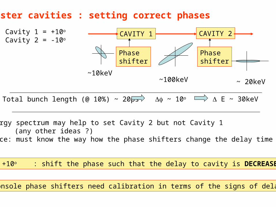
Booster cavities : setting correct phases
Cavity 1 = +10o
Cavity 2 = -10oCAVITY 1
Phaseshifter
CAVITY 2
Phaseshifter
~10keV~100keV ~ 20keV
Total bunch length (@ 10%) ~ 20ps ~ 10o E ~ 30keV
To set +10o : shift the phase such that the delay to cavity is DECREASED by 100
Energy spectrum may help to set Cavity 2 but not Cavity 1(any other ideas ?)
Hence: must know the way how the phase shifters change the delay time
Console phase shifters need calibration in terms of the signs of delays !!!

Setting beam on axis of the booster
Use RF focusing properties in the linac: beam centroid steers if not on axis of the cavity.
BPM-02
Q-01
YAG-02
H&V-03
Principle:
vary Cavity 1 and Cavity2 phases by +/- 30o
and observe no beam motion on YAG or BPM
(focusing / defocusing only !)
This method may not be that effective for Cavity 2 because f ~ 3
How ?
•vary HVCOR-02 and observe beam motion while varying phases•note x at a given - getting smaller ?•repeat until you get fed up with this
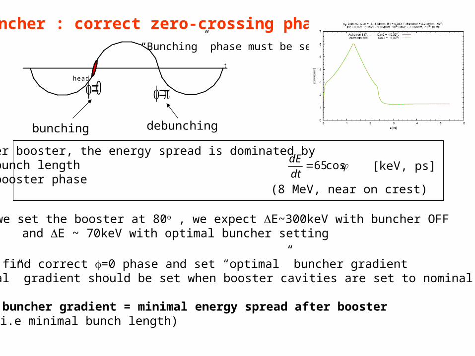
Buncher : correct zero-crossing phase
t
head
bunching debunching
After booster, the energy spread is dominated by a) bunch lengthb) booster phase
“Bunching” phase must be set.
cos65dt
dE[keV, ps]
(8 MeV, near on crest)
If we set the booster at 80o , we expect E~300keV with buncher OFFand E ~ 70keV with optimal buncher setting
Easy to find correct =0 phase and set “optimal” buncher gradient (“optimal” gradient should be set when booster cavities are set to nominal phases
Optimal buncher gradient = minimal energy spread after booster (i.e minimal bunch length)
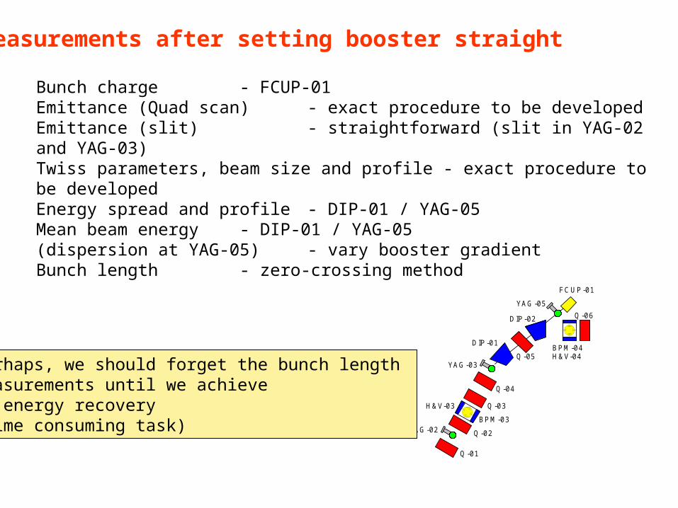
Bunch charge - FCUP-01Emittance (Quad scan) - exact procedure to be developedEmittance (slit) - straightforward (slit in YAG-02 and YAG-03)Twiss parameters, beam size and profile - exact procedure to be developedEnergy spread and profile - DIP-01 / YAG-05Mean beam energy - DIP-01 / YAG-05(dispersion at YAG-05) - vary booster gradientBunch length - zero-crossing method
Measurements after setting booster straight
Q-01
YAG-02 Q-02
BPM-03
H&V-03 Q-03
Q-04
YAG-03
DIP-01
Q-05
DIP-02
YAG-05
FCUP-01
BPM-04H&V-04
Q-06
Perhaps, we should forget the bunch length measurements until we achieve an energy recovery (time consuming task)

On beam energy measurements: effect of offsets and angles
Our E-measurement layout is quite similar to that at (old) TTF Manual
Q-01
YAG-02 Q-02
BPM-03
H&V-03 Q-03
Q-04
YAG-03
DIP-01
Q-05
DIP-02
YAG-05
FCUP-01
BPM-04H&V-04
Q-06
X1X2
X1 X2 dE/E
0 5mm 0.7%-5mm 5mm 1.2%5mm 5mm 0.2%
Perhaps, even without trying too hard, we can get better than 0.5% accuracy inenergy measurements
The same applies to DIP-01 (ARC1) ….
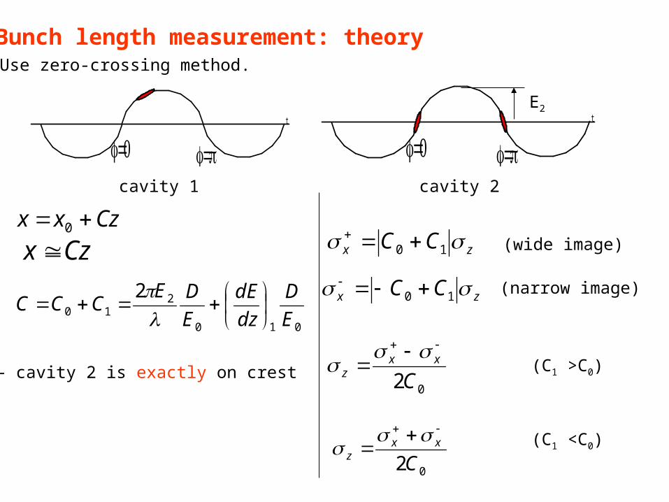
Bunch length measurement: theory Use zero-crossing method.
Czxx 0
t
t
cavity 1 cavity 2
Czx
010
210
2
E
D
dz
dE
E
DECCC
E2
zx CC 10
zx CC 10
(wide image)
(narrow image)
02Cxx
z
02Cxx
z
(C1 >C0)
(C1 <C0)
E2 – cavity 2 is exactly on crest

Bunch length measurement
With existing design (i.e. model) – not trivial
Assume (from the model):After Cavity 1: 4z =7mm; E0 =4.0MeV; D=1m; (dE/dz)1 =25MeV/m; 4E = 160keV
Assume also quite modest E2 = 1.0MeV
C1 = 6.0 4x = 41mm (!!)C0 = 6.8 4x = 46mm (!!)x (wide image) =90mm (!!!!!!)x (narrow image) =5mm
YAG-05 : 30mm diameter
Reduction in Dx to ~0.25m needed (adjust quad Q-05)
New Injector design is expected to produce much lower total energy spread after the booster – hence we’ll be fine !

Injector setup : Summary
Booster-to-FCUP-01
•Thread the beam through booster (coarse)•Crest both cavities (coarse)
- using LLRF signals- use lower Q (10-20pC) initially
Optimise SOL-02 setting beam size and divergence (YAG-02)emittance
•Set the beam on axis of the booster•Thread the beam to FCUP-01 (coarse)•Set correct Q and buncher zero-crossing phase and gradient•Crest booster cavities (fine) and set correct phases•Check electron energy and adjust cavities gradients if needed
re-adjustment of everything starting with SOL-01 may be needed•Set Q-01 to Q-04•Measure baseline beam parameters
emittance, energy spread, but not bunch length at the moment•Calibrate BPM-01 and BPM-02 against Q (procedure to develop by RF group)
Q-01
YAG-02 Q-02
BPM-03
H&V-03 Q-03
Q-04
YAG-03
DIP-01
Q-05
DIP-02
YAG-05
FCUP-01
BPM-04H&V-04
Q-06


The restof
the Injector

Q-01 Linac


Dispersion cancellation (Injector, DIP-01 / DIP-02)
YAG-03
DIP-01
Q-05
DIP-02
YAG-05
FCUP-01
BPM-04H&V-04
Q-06Q-07
Q-08
ARC 2
ST4
Principle: vary booster gradient by 1-3% observe no beam motion on BPM-04if it moves – adjust Q-05
ensure beam centring in Q-05 (it is needed to ensure accuracy but …)
Note: Dx=0.01m x~0.3mm at E/E=3%
Q-01
YAG-02 Q-02
BPM-03
H&V-03 Q-03
Q-04
YAG-03
DIP-01
Q-05
DIP-02
YAG-05
FCUP-01
BPM-04H&V-04
Q-06

FCUP-01
Q-06Q-07
Q-08Q-09
DIP-3
Q-10
YAG-04
Q-11 BPM-05H&V-05
Q-12
ST1
ARC 2
ST4
OTR-01Q-01 Q-02 Q-03 Q-04 Q-05
Dispersion cancellation (Injector, dog-leg)

Main points on setting the injector dog-leg
Make dispersion Dx = 0 at Q-11if Q-10 and Q-12 are identical and symmetric and of correct setting, this should be achieved automatically
If the beam is at an angle when emerging from DIP-03:this does not affect the quads settings
If the beam is offset after DIP-03:quads should be adjusted slightly, e.g. offset = 2mm ~0.3% in quads field adjustment
Setting the ERLP injector dog-leg needs a bit more elaborate procedure

Q-10 Q-11 Q-12BPM-05
BPM-01(ST1)
E0
E
Q-10: too strong
Setting Q-10 (to get Dx=0 at Q-11) and Q-12 (to cancel dispersion)
•Centre the beam at Q-11 (if not done, the beam will move even if D = 0)•Change the booster gradient by 1-3% and fix it there•Wobble Q-11 and observe BPM-05 and BPM-01 (ST1)
if beam moves – adjust Q-10 and try again
now set Q-12 in a regular way …
•Vary booster gradient 1-3% and observe BPM-01 (ST1)adjust Q-12 until beam does not move on BPM-01

Useful formulae: quads related
E
dE
f
xLxQ
0
E
dEDx xD
g
dg
f
xLxg
0
dr
dBg
klf
1
x0
L
fdx
Example: centring in quads
l=0.15m; k=8m-2; 35MeV; L=5m; dg/g=0.1
if dx=0.1mm (screen or BPM resolution) then:
minimal x0 to catch = 0.2mm

Injector: measurements
• Twiss parameters, beam size and profile at the entrance to linacexpected ~3-5m and ~0beam size ~ 3-5mm FWHM and round
Skip other measurements until energy recovery is achieved
•Emittance measurement at the entrance to linac•Energy spread and profile at the entrance to linac •Check R56 in the Injector line
use time-of-arrival detection system on BPM-01 (ST1)
Note : OTR-01 (ST1) has a hole of 15mm diameter at the centrehence you need to steer the beam off-centre to be able to see it !!

The rest of the Injector : Summary
•Set DIP-01 and DIP-2 (dispersion suppression)
•Thread beam through dog-leg section (coarse)
•Set dog-leg section (fine); dispersion suppression
•Match the beam to main linacperhaps beam size and position only
•Beam measurements probably, need none at the energy recovery stage
YAG-03
DIP-01
Q-05
DIP-02
YAG-05
FCUP-01
BPM-04H&V-04
Q-06Q-07
Q-08
ARC 2
ST4
FCUP-01
Q-06Q-07
Q-08Q-09
DIP-3
Q-10
YAG-04
Q-11 BPM-05H&V-05
Q-12
INJECTOR ST1
ARC 2
ST4
OTR-01Q-01 Q-02 Q-03 Q-04 Q-05