alcotec aluminum technical guide
TRANSCRIPT
AlcoTec AluminumTechnical Guide
1
Contents
AlcoTec Aluminum Wire & Equipment Technical Guide
Table of Contents
Environmental Health and Safety ......................................................................................................................................... 3
Technical Services
Heat Treatable & Non-Heat Treatable Base & Fillers ............................................................................................................. 6
Filler Alloys: Chemical Composition Limits & Physical Properties ......................................................................................... 7
Conversion Factors ............................................................................................................................................................ 7
Welded Joint Strength ......................................................................................................................................................... 8
Typical Tensile Properties - Groove Welds ............................................................................................................................ 9
Weld Profiles ...................................................................................................................................................................... 10
Weld Control Characteristics ............................................................................................................................................. 11
Parameter Changes & Current Density............................................................................................................................... 11
Backing Bars ..................................................................................................................................................................... 12
Bend Testing Aluminum ..................................................................................................................................................... 13
Atmospheric Conditions Affect Weld Quality ...................................................................................................................... 14
Feedability ......................................................................................................................................................................... 15
Excessive Face Reinforcement .......................................................................................................................................... 16
Dilution .............................................................................................................................................................................. 17
Aluminum Alloys ................................................................................................................................................................ 18
Heat-Treatable and Non Heat-Treatable Alloys & the Heat Affected Zone (HAZ) ................................................................. 19
Considerations When Repairing Aluminum Structures ....................................................................................................... 20
Shielding Gas for Arc Welding Aluminum ........................................................................................................................... 21
Easy Weld Quality Tests ..................................................................................................................................................... 22
Weld Cracking ................................................................................................................................................................... 24
Performance Improvement - Increasing Wire Diameter ...................................................................................................... 26
Filler Alloy for Welding 6061-T6 .......................................................................................................................................... 27
The Affect of Texture on Anodizing ..................................................................................................................................... 28
Recommended Welding Parameters ................................................................................................................................. 29
Aluminum Filler Alloy Chart ................................................................................................................................................ 30
Education
Welder Certification and Qualification ................................................................................................................................. 34
AlcoTec School of Aluminum Welding Technology ............................................................................................................. 35
AlcoTec School of Aluminum Welding Technology Course Outline ..................................................................................... 36
Classroom ......................................................................................................................................................................... 36
Laboratory ......................................................................................................................................................................... 36

“We take the concerns of our customers to heart.” – Todd Peters, Operations Manager, AlcoTec Wire Corporation
Our mission: To provide our customers with the most cost-effective solutions for their welding and cutting applications. Through technological leadership, the most reliable products and deliveries, and continuous improvement of our processes, we will delight our customers, employees, shareholders, and community. Our values: Integrity, Progress, Quality, Leadership, and Teamwork.
Environmental Health and Safety
At AlcoTec, we put a heavy emphasis on environmental health and safety, and are constantly looking for ways to improve our operations. Our facilities and products meet or exceed all applicable governmental requirements and standards. We educate and encourage our employees to comply with EHS policies.
AlcoTec is a subsidiary of ESAB Group, Inc., - the first global company to achieve both ISO 14001 (1999) and OHSAS 18001 (2006) certifications. Furthermore, we are proud to be ISO 9001 certified.
The AlcoTec® advantage.
At AlcoTec®, aluminum welding isn’t just part of our business, it’s our only business.
Since 1984, AlcoTec aluminum wire has been world renowned for quality, consistency,
and performance.
And premium aluminum wire is just the start of what we offer. Our goal is to help
you work smarter, faster, and better. With continuous innovation, we maximize your
productivity while minimizing your costs by:
Providing service and support that goes the extra mile to keep you up and running
Helping you take your aluminum welding skills to the next level through expert training
Becoming the ultimate partner you can trust for years to come
At AlcoTec, integrity is just as important to us as the quality of our product.
We strive to treat everyone with the utmost respect. We measure our
success by the number of long-term customers who trust us and
value what we bring to the table. And we appreciate it when
our customers say how much they like working with us.
We invite you to get to know AlcoTec’s products,
equipment, and technical services.
Technical Services
5
Technical Services
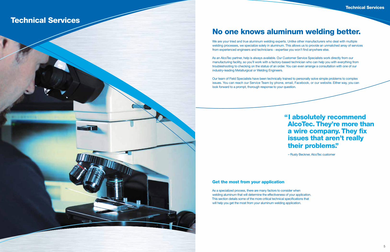
No one knows aluminum welding better. We are your tried and true aluminum welding experts. Unlike other manufacturers who deal with multiple welding processes, we specialize solely in aluminum. This allows us to provide an unmatched array of services from experienced engineers and technicians - expertise you won’t find anywhere else.
As an AlcoTec partner, help is always available. Our Customer Service Specialists work directly from our manufacturing facility, so you’ll work with a factory-based technician who can help you with everything from troubleshooting to checking on the status of an order. You can even arrange a consultation with one of our industry-leading Metallurgical or Welding Engineers.
Our team of Field Specialists have been technically trained to personally solve simple problems to complex issues. You can reach our Service Team by phone, email, Facebook, or our website. Either way, you can look forward to a prompt, thorough response to your question.
“I absolutely recommend AlcoTec. They’re more than a wire company. They fix issues that aren’t really their problems.” – Rusty Beckner, AlcoTec customer
Get the most from your application As a specialized process, there are many factors to consider when welding aluminum that will determine the effectiveness of your application. This section details some of the more critical technical specifications that will help you get the most from your aluminum welding application.

6 7
Technical Services Technical Services
Filler Alloys: Chemical Composition Limits & Physical Properties
AlloySilicon
Si
Iron
Fe
Copper
Cu
Manganese
Mn
Magnesium
Mg
Chromium
Cr
Zinc
Z
Titanium
Ti
Others (1) Aluminum
Al (min)
Approximate Melting Range,
°F
Density
lbs/in3
Post (4)Anodize
Color TintEach Total
1100 Si + Fe = 0.95 0.05-0.20 0.05 — — 0.10 — 0.05 0.15 99.00 1190-1215 .098 Golden
1188 0.06 0.06 0.005 0.01 0.01 — 0.03 0.01 0.01 — 99.88 1215-1220 .0975 Clear
1199 0.006 0.006 0.006 0.002 0.006 — 0.006 0.002 0.002 — 99.99 1220 .0975 Clear
1350 0.10 0.40 0.05 0.01 — 0.01 0.05 — 0.03 0.10 99.50 1195-1215 .0975 Clear
206.0 0.10 0.15 4.2-5.0 0.20-0.50 0.15-0.35 — 0.10 0.15-0.30 0.05 (2) 0.15 Rmnd 1060-1200 .101 Golden
2319 0.20 0.30 5.8-6.8 0.20-0.40 0.02 — 0.10 0.10-0.20 0.05 (3) 0.15 Rmnd 1010-1190 .100 Golden
357.0 6.5-7.5 0.15 0.05 0.03 0.45-0.6 — 0.05 0.20 0.05 0.15 Rmnd 1040-1140 .098 Gray
4008 6.5-7.5 0.09 0.05 0.05 0.30-0.45 — 0.05 0.04-0.15 0.05 0.15 Rmnd 1035-1135 .097 Gray
4009 4.5-5.5 0.20 1.0-1.5 0.10 0.45-0.6 — 0.10 0.20 0.05 0.15 Rmnd 1015-1150 .098 Gray
4010 6.5-7.5 0.20 0.20 0.10 0.30-0.45 — 0.10 0.20 0.05 0.15 Rmnd 1035-1135 .097 Gray
4043 4.5-6.0 0.8 0.30 0.05 0.05 — 0.10 0.20 0.05 0.15 Rmnd 1065-1170 .097 Gray
4047 11.0-13.0 0.8 0.30 0.15 0.10 — 0.20 — 0.05 0.15 Rmnd 1070-1080 .096 Gray-Black
4145 9.3-10.7 0.8 3.3-4.7 0.15 0.15 0.15 0.20 — 0.05 0.15 Rmnd 970-1085 .099 Gray-Black
4643 3.6-4.6 0.8 0.10 0.05 0.10-0.30 — 0.10 0.15 0.05 0.15 Rmnd 1065-1175 .097 Gray
5183 0.40 0.40 0.10 0.50-1.0 4.3-5.2 0.05-0.25 0.25 0.15 0.05 0.15 Rmnd 1075-1180 .096 White
5356 0.25 0.40 0.10 0.05-0.20 4.5-5.5 0.05-0.20 0.10 0.06-0.20 0.05 0.15 Rmnd 1060-1175 .096 White
5554 0.25 0.40 0.10 0.50-1.0 2.4-3.0 0.05-0.20 0.25 0.05-0.20 0.05 0.15 Rmnd 1115-1195 .097 White
5556 0.25 0.40 0.10 0.50-1.0 4.7-5.5 0.05-0.20 0.25 0.05-0.20 0.05 0.15 Rmnd 1065-1175 .096 White
5654 Si + Fe = 0.45 0.05 0.01 3.1-3.9 0.15-0.35 0.20 0.05-0.15 0.05 0.15 Rmnd 1100-1190 .096 White
5087 0.25 0.40 0.05 0.7-1.1 4.5-5.2 0.05-0.25 0.25 0.15 0.05 (5) 0.15 Rmnd 1054-1180 .096 White
5754 0.40 0.40 0.10 0.50 2.6-3.6 0.30 0.20 0.15 0.15 (6) 0.15 Rmnd 1095-1195 .097 White
(1) Berylium shall not exceed 0.0003% (4) Use filler alloy chart for color matching (2) Nickel shall not exceed 0.05% (5) 0.10-0.20 Zr (3) Vanadium shall be 0.05-0.15% and Zirconium shall be 0.10-0.25% (6) 0.10-0.6 Mn + Cr
Conversion Factors
Fraction Decimal mm ft/lb. m/kgApproximate Wire Gauge
— .030 0.8 1215 816 20.5
— .035 0.9 900 605 19
— .040 1.0 704 473 18
3/64 .047 1.2 520 349 17
1/16 .062 1.6 290 195 14
— .071 1.8 220 150 13
— .079 2.0 172 115 12
3/32 .093 2.4 130 87 11
1/8 .125 3.2 70 47 8
5/32 .156 4.0 45 30 6.5
3/16 .187 4.7 31 21 4.5
1/4 .250 6.3 20 13 2
Convert From Convert To Multiply By
inches millimeters 25.4
millimeters inches .03937
square inches square millimeters 645.2
square millimeters square inches .001552
fluid ounces millimeters 29.57
millimeters fluid ounces .03381
ounces grams 28.35
grams ounces .03527
pounds kilograms .4536
kilograms pounds 2.205
Newtons/mm pounds/inch 145.04
pounds/inch Newtons/mm .006895
Heat Treatable & Non-Heat Treatable Base & Fillers
Aluminum Alloy Designation Tree
The Aluminum Association uses a four digit numbering system for designating wrought aluminum and wrought aluminum alloys. The image above shows the wrought alloy groups as well as a few examples of common products from each group. The significance of each number is described below.
1st Digit – Identifies the major alloying element.
2nd Digit – Identifies the rendition of an alloy. For example, 5356 is the 3rd rendition of the original base alloy 5056.
3rd and 4th Digits:
In the 1XXX group, the last two digits indicate the minimum aluminum percentage. For example, alloy 1188 has a minimum purity of 99.88% aluminum. Alloy 1350 has a minimum purity of 99.50% aluminum.
In the 2XXX – 8XXX groups, the last two digits serve merely as counters. For example, 3004 was the next manganese alloyed chemistry after 3003.
8 9
Technical Services Technical Services
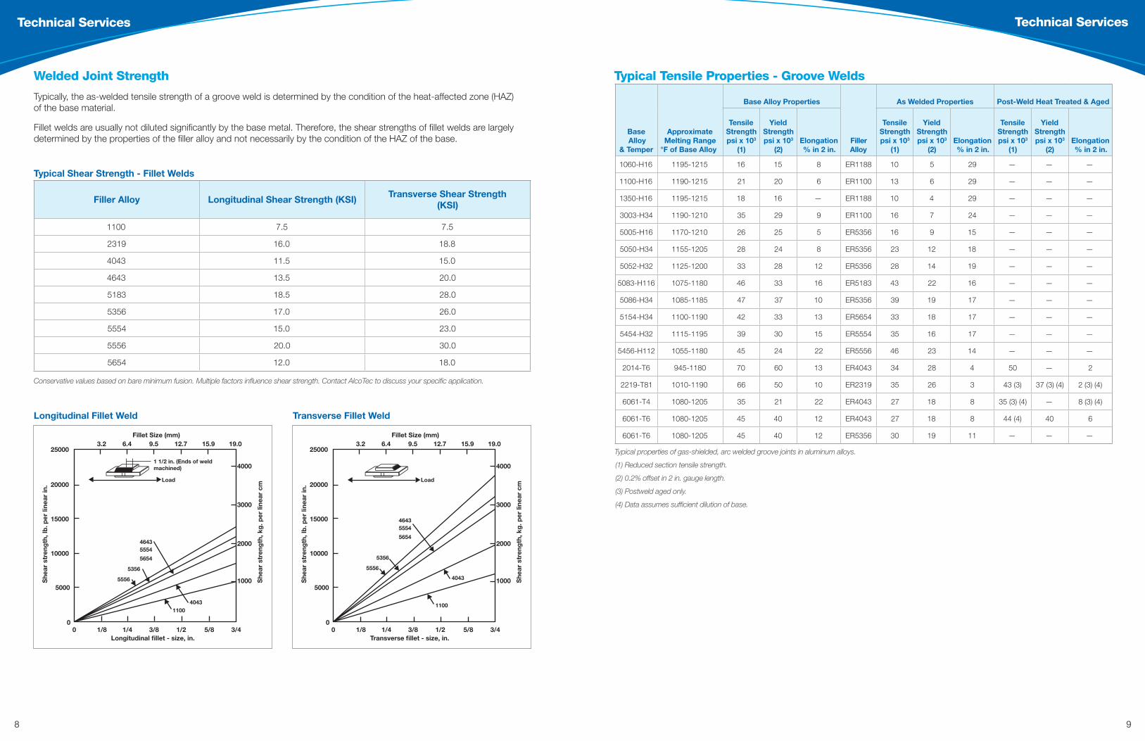
Typical properties of gas-shielded, arc welded groove joints in aluminum alloys.
(1) Reduced section tensile strength.
(2) 0.2% offset in 2 in. gauge length.
(3) Postweld aged only.
(4) Data assumes sufficient dilution of base.
Typical Tensile Properties - Groove Welds
Base Alloy
& Temper
Approximate Melting Range
°F of Base Alloy
Base Alloy Properties
Filler Alloy
As Welded Properties Post-Weld Heat Treated & Aged
Tensile Strength psi x 103
(1)
Yield Strength psi x 103
(2)Elongation % in 2 in.
Tensile Strength psi x 103
(1)
Yield Strength psi x 103
(2)Elongation % in 2 in.
Tensile Strength psi x 103
(1)
Yield Strength psi x 103
(2)Elongation % in 2 in.
1060-H16 1195-1215 16 15 8 ER1188 10 5 29 — — —
1100-H16 1190-1215 21 20 6 ER1100 13 6 29 — — —
1350-H16 1195-1215 18 16 — ER1188 10 4 29 — — —
3003-H34 1190-1210 35 29 9 ER1100 16 7 24 — — —
5005-H16 1170-1210 26 25 5 ER5356 16 9 15 — — —
5050-H34 1155-1205 28 24 8 ER5356 23 12 18 — — —
5052-H32 1125-1200 33 28 12 ER5356 28 14 19 — — —
5083-H116 1075-1180 46 33 16 ER5183 43 22 16 — — —
5086-H34 1085-1185 47 37 10 ER5356 39 19 17 — — —
5154-H34 1100-1190 42 33 13 ER5654 33 18 17 — — —
5454-H32 1115-1195 39 30 15 ER5554 35 16 17 — — —
5456-H112 1055-1180 45 24 22 ER5556 46 23 14 — — —
2014-T6 945-1180 70 60 13 ER4043 34 28 4 50 — 2
2219-T81 1010-1190 66 50 10 ER2319 35 26 3 43 (3) 37 (3) (4) 2 (3) (4)
6061-T4 1080-1205 35 21 22 ER4043 27 18 8 35 (3) (4) — 8 (3) (4)
6061-T6 1080-1205 45 40 12 ER4043 27 18 8 44 (4) 40 6
6061-T6 1080-1205 45 40 12 ER5356 30 19 11 — — —
Typical Shear Strength - Fillet Welds
Filler Alloy Longitudinal Shear Strength (KSI)Transverse Shear Strength
(KSI)
1100 7.5 7.5
2319 16.0 18.8
4043 11.5 15.0
4643 13.5 20.0
5183 18.5 28.0
5356 17.0 26.0
5554 15.0 23.0
5556 20.0 30.0
5654 12.0 18.0
Conservative values based on bare minimum fusion. Multiple factors influence shear strength. Contact AlcoTec to discuss your specific application.
Welded Joint Strength
Typically, the as-welded tensile strength of a groove weld is determined by the condition of the heat-affected zone (HAZ) of the base material.
Fillet welds are usually not diluted significantly by the base metal. Therefore, the shear strengths of fillet welds are largely determined by the properties of the filler alloy and not necessarily by the condition of the HAZ of the base.
Longitudinal Fillet Weld Transverse Fillet Weld
250003.2
1/80
0Longitudinal fillet - size, in.
Load
46435554
5654
5356
40431100
5556
1 1/2 in. (Ends of weldmachined)
Fillet Size (mm)
1/4 3/8 1/2 5/8 3/4
6.4 9.5 12.7 15.9 19.0
20000
15000
10000
5000
4000
3000
2000
1000She
ar s
tren
gth
, lb
. per
line
ar in
.
She
ar s
tren
gth
, kg
. per
line
ar c
m
�
�
�
��
�
�
250003.2
1/80
0Transverse fillet - size, in.
Load
46435554
5654
5356
4043
1100
5556
Fillet Size (mm)
1/4 3/8 1/2 5/8 3/4
6.4 9.5 12.7 15.9 19.0
20000
15000
10000
5000
4000
3000
2000
1000She
ar s
tren
gth
, lb
. per
line
ar in
.
She
ar s
tren
gth
, kg
. per
line
ar c
m
�
�
��
�
�
�

10 11
Technical Services Technical Services
Weld Control Characteristics
Parameter Changes & Current Density
Recommendations
Root Pass Shorter Arc
Finish Pass Longer Arc
5XXX AlloysShorter Arc
Lower Arc Voltage Higher Amperage
4XXX AlloysLonger Arc
Higher Arc Voltage Lower Amperage
Increasing arc voltage reduces arc energy concentration
Increasing arc voltage decreases:
Wire to work piece gap
Energy distribution width
.047 in. wire diameter = (.0235 in.)2 x π = .0017 in.2 section
Arc Length (Voltage)
Pen
etra
tio
n (A
mp
erag
e)
Low
Short
Hig
h
Long
20V x 150A = 3 kW 23V x 131A = 3 kW
88 kJ/in2 sec 77 kJ/in2 sec
0.32” 0.43”
Weld Profiles
Weld Profile Troubleshooting Guide
Problem Example (Groove Weld) Example (Fillet Weld) Possible Solution
Excessive Convexity/ Reinforcement
Reduced fatigue strength
Increase arc length Increase torch angle Increase travel speed
Insufficient Leg Length Reduced mechanical
propertiesN/A
Change torch angle Change torch position1
Insufficient Throat/Underfill Reduced mechanical
properties
Reduce cooling rate Increase electrode feed rate
Decrease travel speed Decrease arc length
Undercut Reduced mechanical
properties
Change torch position to compensate for:
Dissimilar section sizes Dissimilar thermal conductivity
Out-of-position welds
Overlap Severe reduction in fatigue strength
Increase voltage Decrease wire speed Increase travel speed
Incomplete Penetration/Lack of Fusion
Reduced weld strength and increased sensitivity
to crack propagation
Increase amperage Decrease arc length
Decrease torch forehand angle Increase travel speed
(1) For example, the thermal conductivity of 5083 is 32% less than that of 6061 because of the higher magnesium content. This requires more heat input into the 6061 alloy.
Base Thickness T ≤ 3/8
3/8 < T ≤ 3/4 T > 3/4
Max Reinforcement 3/32 1/8
3/16
Width of Weld Face ≤ 5/16
>5/16 to <1 ≥1
Max Convexity 1/16 1/8
3/16
Acceptable Weld Profile Criteria per AWS D1.2
12 13
Technical Services Technical Services
Bend Testing Aluminum
Thickness of Specimen Bend Mandrel Diameter Materials
3/8 t
1-1/2 4t
M21 and M22
1/8 t (<1/8)
2-1/16 16-1/2t
M23* or F23 Welds
3/8 t
2-1/2 6-2/3t
M25 and Annealed M23*
*Note: Temper condition can also have an influence on the testing criteria.
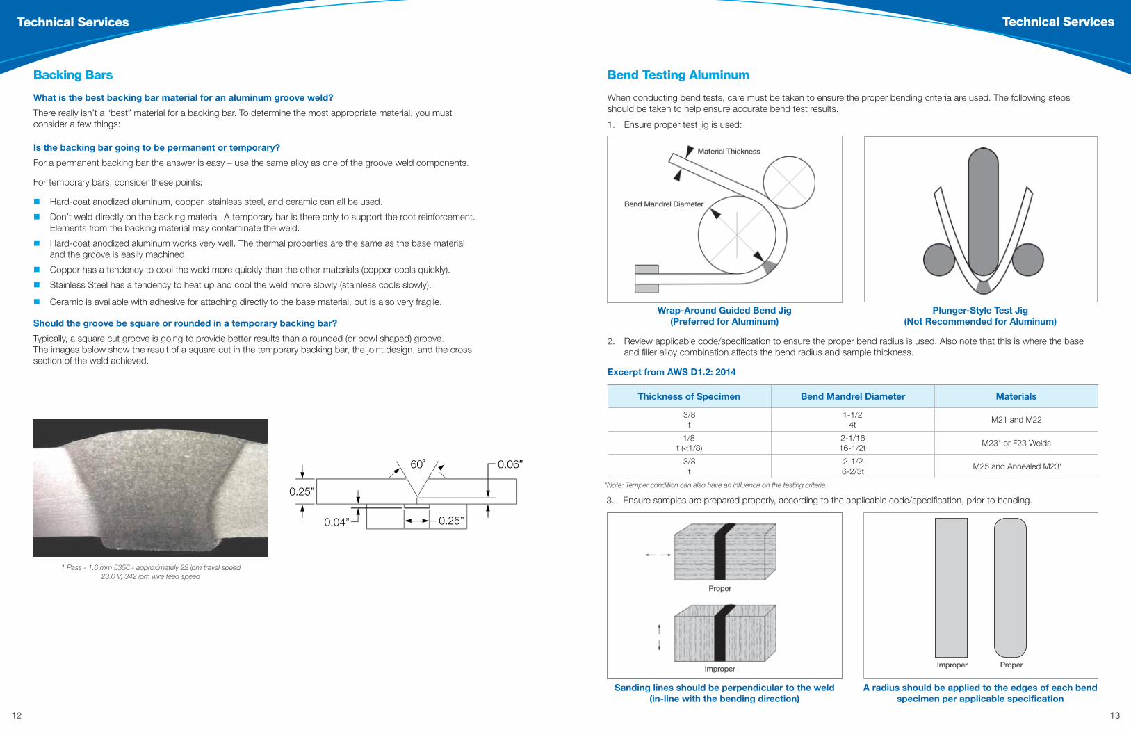
When conducting bend tests, care must be taken to ensure the proper bending criteria are used. The following steps should be taken to help ensure accurate bend test results.
1. Ensure proper test jig is used:
Wrap-Around Guided Bend Jig (Preferred for Aluminum)
Sanding lines should be perpendicular to the weld (in-line with the bending direction)
Plunger-Style Test Jig (Not Recommended for Aluminum)
A radius should be applied to the edges of each bend specimen per applicable specification
2. Review applicable code/specification to ensure the proper bend radius is used. Also note that this is where the base and filler alloy combination affects the bend radius and sample thickness.
Excerpt from AWS D1.2: 2014
3. Ensure samples are prepared properly, according to the applicable code/specification, prior to bending.
Proper
Material Thickness
Bend Mandrel Diameter
ImproperImproper Proper
Backing Bars
0.25”
0.25”
60˚
0.04”
0.06”
� �
�
�
�
�
� �
��
1 Pass - 1.6 mm 5356 - approximately 22 ipm travel speed 23.0 V; 342 ipm wire feed speed
What is the best backing bar material for an aluminum groove weld?
There really isn’t a “best” material for a backing bar. To determine the most appropriate material, you must consider a few things:
Is the backing bar going to be permanent or temporary?
For a permanent backing bar the answer is easy – use the same alloy as one of the groove weld components.
For temporary bars, consider these points:
Hard-coat anodized aluminum, copper, stainless steel, and ceramic can all be used.
Don’t weld directly on the backing material. A temporary bar is there only to support the root reinforcement. Elements from the backing material may contaminate the weld.
Hard-coat anodized aluminum works very well. The thermal properties are the same as the base material and the groove is easily machined.
Copper has a tendency to cool the weld more quickly than the other materials (copper cools quickly).
Stainless Steel has a tendency to heat up and cool the weld more slowly (stainless cools slowly).
Ceramic is available with adhesive for attaching directly to the base material, but is also very fragile.
Should the groove be square or rounded in a temporary backing bar?
Typically, a square cut groove is going to provide better results than a rounded (or bowl shaped) groove. The images below show the result of a square cut in the temporary backing bar, the joint design, and the cross section of the weld achieved.
14 15
Technical Services Technical Services
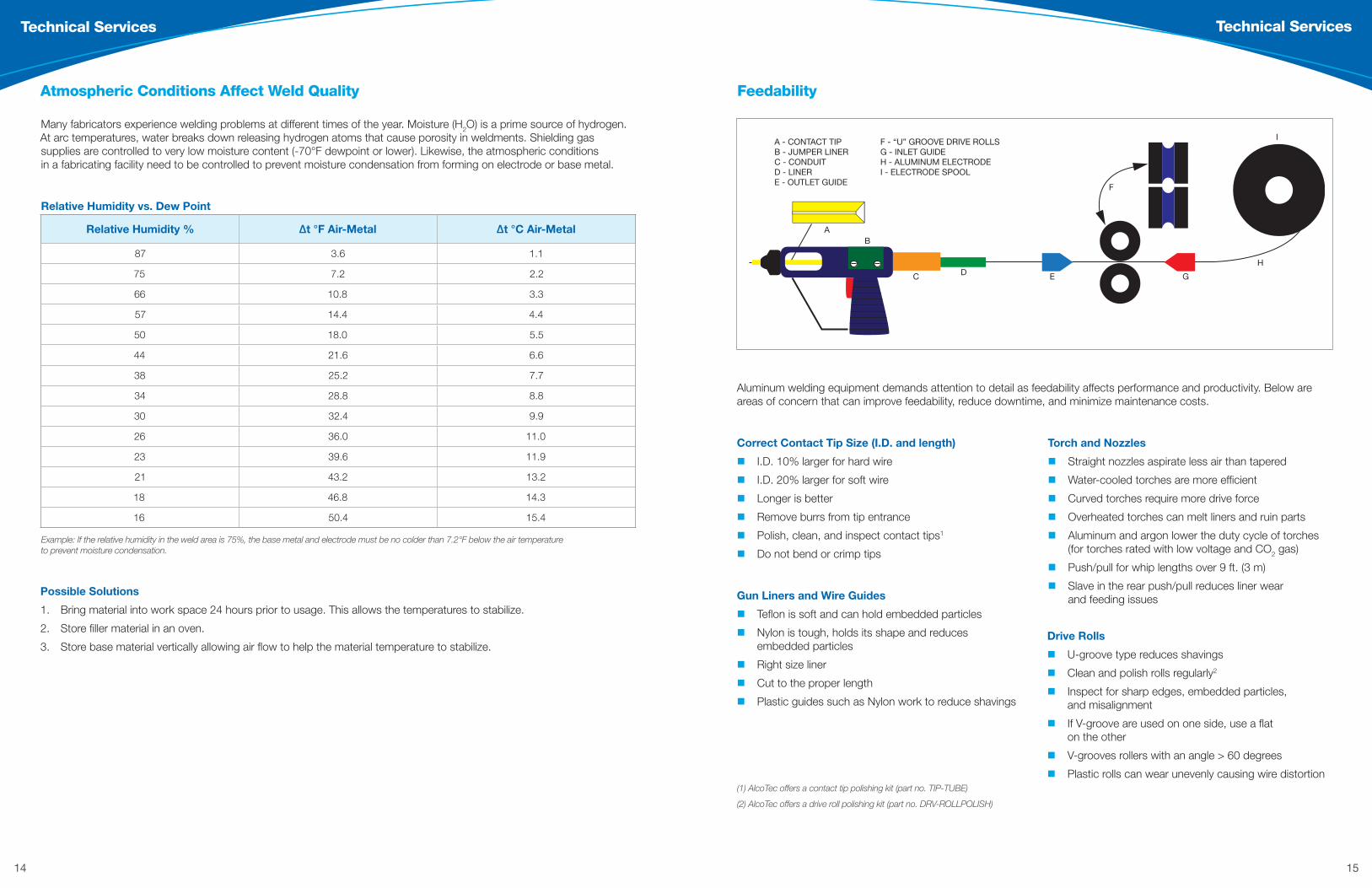
Feedability
AB
C D E G
F
H
IA - CONTACT TIPB - JUMPER LINERC - CONDUITD - LINERE - OUTLET GUIDE
F - “U” GROOVE DRIVE ROLLSG - INLET GUIDEH - ALUMINUM ELECTRODEI - ELECTRODE SPOOL
Aluminum welding equipment demands attention to detail as feedability affects performance and productivity. Below are areas of concern that can improve feedability, reduce downtime, and minimize maintenance costs.
Correct Contact Tip Size (I.D. and length)
I.D. 10% larger for hard wire
I.D. 20% larger for soft wire
Longer is better
Remove burrs from tip entrance
Polish, clean, and inspect contact tips1
Do not bend or crimp tips
Drive Rolls
U-groove type reduces shavings
Clean and polish rolls regularly2
Inspect for sharp edges, embedded particles, and misalignment
If V-groove are used on one side, use a flat on the other
V-grooves rollers with an angle > 60 degrees
Plastic rolls can wear unevenly causing wire distortion
Gun Liners and Wire Guides
Teflon is soft and can hold embedded particles
Nylon is tough, holds its shape and reduces embedded particles
Right size liner
Cut to the proper length
Plastic guides such as Nylon work to reduce shavings
Torch and Nozzles
Straight nozzles aspirate less air than tapered
Water-cooled torches are more efficient
Curved torches require more drive force
Overheated torches can melt liners and ruin parts
Aluminum and argon lower the duty cycle of torches (for torches rated with low voltage and CO2 gas)
Push/pull for whip lengths over 9 ft. (3 m)
Slave in the rear push/pull reduces liner wear and feeding issues
(1) AlcoTec offers a contact tip polishing kit (part no. TIP-TUBE)
(2) AlcoTec offers a drive roll polishing kit (part no. DRV-ROLLPOLISH)
Possible Solutions
1. Bring material into work space 24 hours prior to usage. This allows the temperatures to stabilize.
2. Store filler material in an oven.
3. Store base material vertically allowing air flow to help the material temperature to stabilize.
Example: If the relative humidity in the weld area is 75%, the base metal and electrode must be no colder than 7.2°F below the air temperature to prevent moisture condensation.
Relative Humidity vs. Dew Point
Relative Humidity % ∆t °F Air-Metal ∆t °C Air-Metal
87 3.6 1.1
75 7.2 2.2
66 10.8 3.3
57 14.4 4.4
50 18.0 5.5
44 21.6 6.6
38 25.2 7.7
34 28.8 8.8
30 32.4 9.9
26 36.0 11.0
23 39.6 11.9
21 43.2 13.2
18 46.8 14.3
16 50.4 15.4
Many fabricators experience welding problems at different times of the year. Moisture (H2O) is a prime source of hydrogen. At arc temperatures, water breaks down releasing hydrogen atoms that cause porosity in weldments. Shielding gas supplies are controlled to very low moisture content (-70°F dewpoint or lower). Likewise, the atmospheric conditions in a fabricating facility need to be controlled to prevent moisture condensation from forming on electrode or base metal.
Atmospheric Conditions Affect Weld Quality
16 17
Technical Services Technical Services
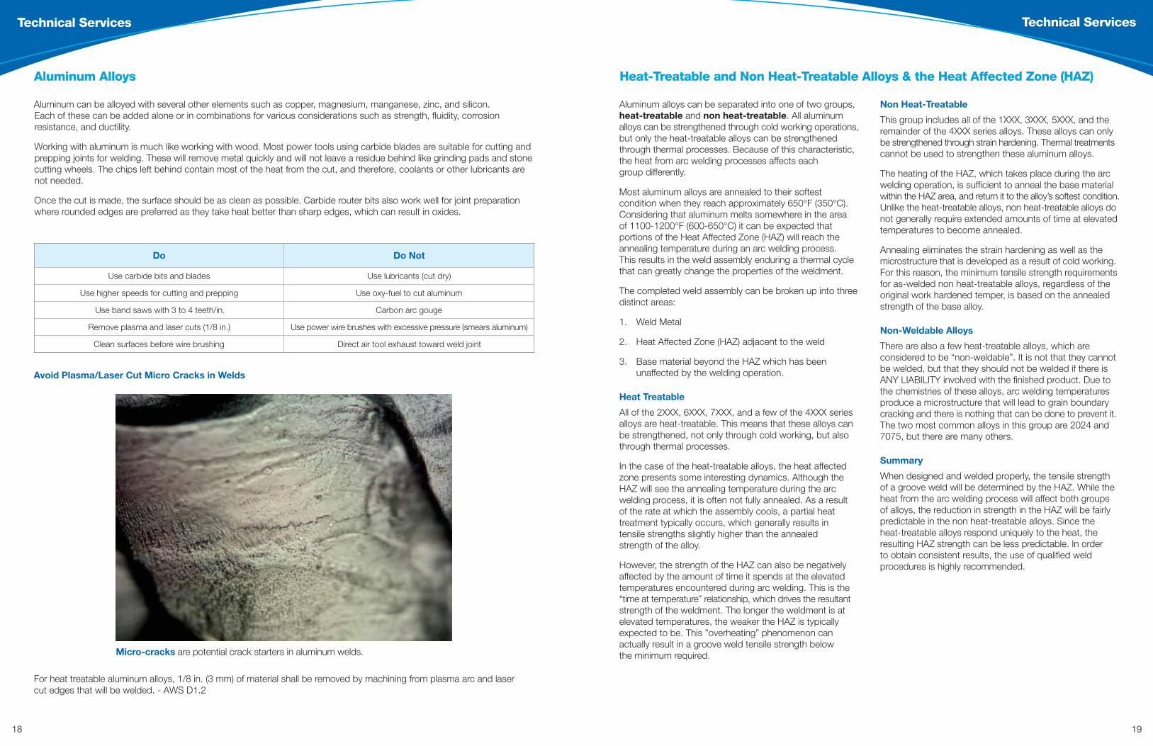
Dilution
Dilution Ratios of Joints
Weld Composition: Dilution Effect
A weld essentially becomes a new alloy made up of the base and filler alloys. Dilution is the amount of base alloy that mixes with the filler alloy to create the new weld alloy. There are multiple factors that affect the amount of base dilution into the weld puddle. Although the welding parameters can change the dilution ratio, the easiest way to actually control it is by modifying the joint design (see images below).
Depending on the alloys involved, simply changing the joint design may be enough to change the tensile strength of an as-welded groove assembly. The image below shows the theoretical difference in dilution ratios by modifying the joint design from a square butt to a single V-groove. The amount of base metal that is diluting the filler alloy is reduced in the single V, making the overall magnesium content of the new weld alloy significantly higher.
Depending on the other variables involved, this may be all that is needed to go from just missing the minimum tensile strength to achieving it regularly (and with room to spare). Another benefit of reducing the amount of base metal dilution is that the probability of stress cracking is typically reduced.
80% Filler Metal 20% Base Metal
60% Filler Metal 40% Base Metal
20% Filler Metal 80% Base Metal
1.7% Mg
3.2% Mg
60% Filler Metal 40% Base Metal
20% Filler Metal 80% Base Metal
Base Plate 6061
Filler Metal 5356
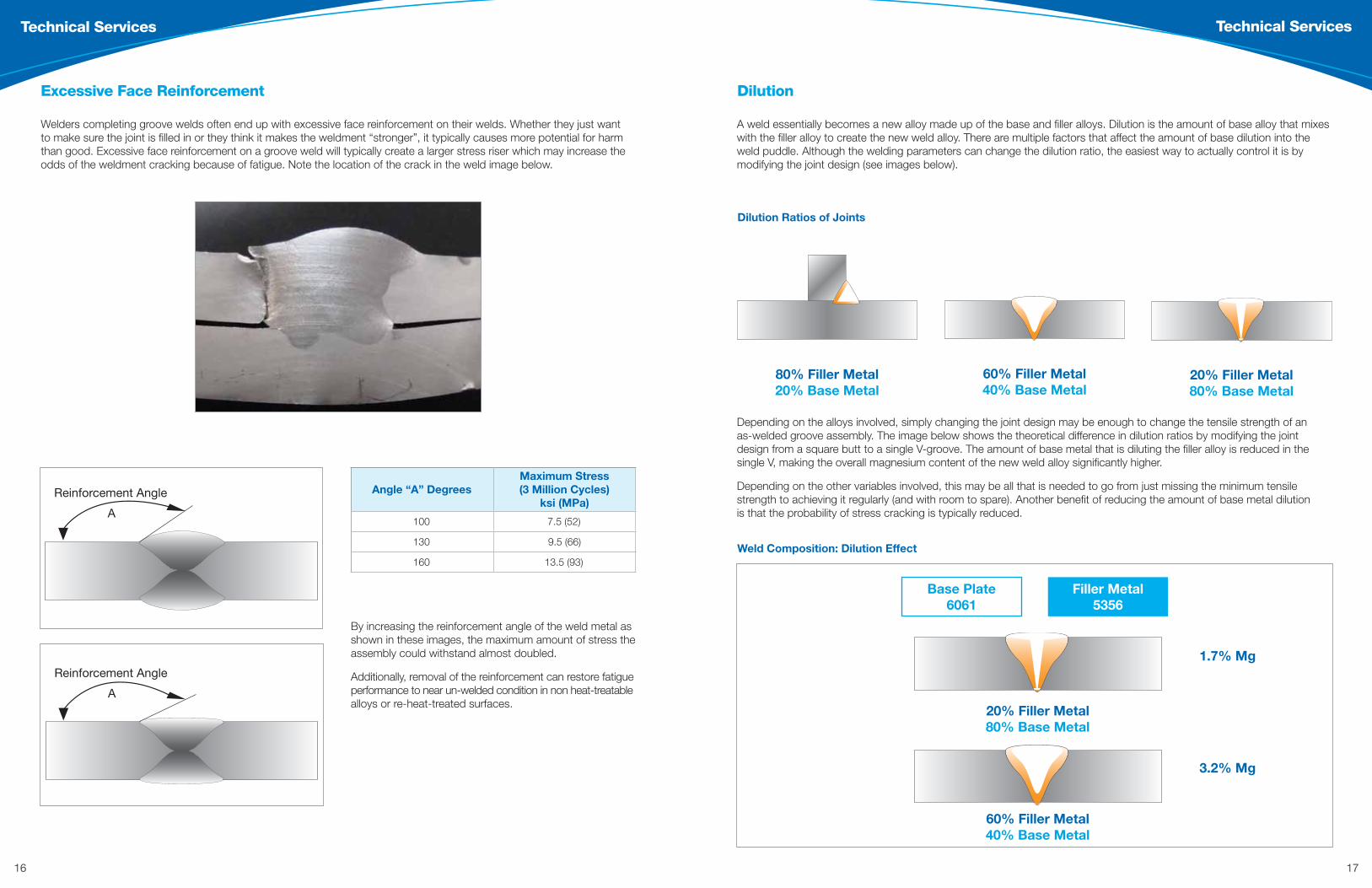
Angle “A” DegreesMaximum Stress (3 Million Cycles)
ksi (MPa)
100 7.5 (52)
130 9.5 (66)
160 13.5 (93)
Welders completing groove welds often end up with excessive face reinforcement on their welds. Whether they just want to make sure the joint is filled in or they think it makes the weldment “stronger”, it typically causes more potential for harm than good. Excessive face reinforcement on a groove weld will typically create a larger stress riser which may increase the odds of the weldment cracking because of fatigue. Note the location of the crack in the weld image below.
Excessive Face Reinforcement
Reinforcement Angle
A
Reinforcement Angle
A
By increasing the reinforcement angle of the weld metal as shown in these images, the maximum amount of stress the assembly could withstand almost doubled.
Additionally, removal of the reinforcement can restore fatigue performance to near un-welded condition in non heat-treatable alloys or re-heat-treated surfaces.
18 19
Technical Services Technical Services
Heat-Treatable and Non Heat-Treatable Alloys & the Heat Affected Zone (HAZ)
Aluminum alloys can be separated into one of two groups, heat-treatable and non heat-treatable. All aluminum alloys can be strengthened through cold working operations, but only the heat-treatable alloys can be strengthened through thermal processes. Because of this characteristic, the heat from arc welding processes affects each group differently.
Most aluminum alloys are annealed to their softest condition when they reach approximately 650°F (350°C). Considering that aluminum melts somewhere in the area of 1100-1200°F (600-650°C) it can be expected that portions of the Heat Affected Zone (HAZ) will reach the annealing temperature during an arc welding process. This results in the weld assembly enduring a thermal cycle that can greatly change the properties of the weldment.
The completed weld assembly can be broken up into three distinct areas:
1. Weld Metal
2. Heat Affected Zone (HAZ) adjacent to the weld
3. Base material beyond the HAZ which has been unaffected by the welding operation.
Heat Treatable
All of the 2XXX, 6XXX, 7XXX, and a few of the 4XXX series alloys are heat-treatable. This means that these alloys can be strengthened, not only through cold working, but also through thermal processes.
In the case of the heat-treatable alloys, the heat affected zone presents some interesting dynamics. Although the HAZ will see the annealing temperature during the arc welding process, it is often not fully annealed. As a result of the rate at which the assembly cools, a partial heat treatment typically occurs, which generally results in tensile strengths slightly higher than the annealed strength of the alloy.
However, the strength of the HAZ can also be negatively affected by the amount of time it spends at the elevated temperatures encountered during arc welding. This is the “time at temperature” relationship, which drives the resultant strength of the weldment. The longer the weldment is at elevated temperatures, the weaker the HAZ is typically expected to be. This ”overheating” phenomenon can actually result in a groove weld tensile strength below the minimum required.
Non Heat-Treatable
This group includes all of the 1XXX, 3XXX, 5XXX, and the remainder of the 4XXX series alloys. These alloys can only be strengthened through strain hardening. Thermal treatments cannot be used to strengthen these aluminum alloys.
The heating of the HAZ, which takes place during the arc welding operation, is sufficient to anneal the base material within the HAZ area, and return it to the alloy’s softest condition. Unlike the heat-treatable alloys, non heat-treatable alloys do not generally require extended amounts of time at elevated temperatures to become annealed.
Annealing eliminates the strain hardening as well as the microstructure that is developed as a result of cold working. For this reason, the minimum tensile strength requirements for as-welded non heat-treatable alloys, regardless of the original work hardened temper, is based on the annealed strength of the base alloy.
Non-Weldable Alloys
There are also a few heat-treatable alloys, which are considered to be “non-weldable”. It is not that they cannot be welded, but that they should not be welded if there is ANY LIABILITY involved with the finished product. Due to the chemistries of these alloys, arc welding temperatures produce a microstructure that will lead to grain boundary cracking and there is nothing that can be done to prevent it. The two most common alloys in this group are 2024 and 7075, but there are many others.
Summary
When designed and welded properly, the tensile strength of a groove weld will be determined by the HAZ. While the heat from the arc welding process will affect both groups of alloys, the reduction in strength in the HAZ will be fairly predictable in the non heat-treatable alloys. Since the heat-treatable alloys respond uniquely to the heat, the resulting HAZ strength can be less predictable. In order to obtain consistent results, the use of qualified weld procedures is highly recommended.
Do Do Not
Use carbide bits and blades Use lubricants (cut dry)
Use higher speeds for cutting and prepping Use oxy-fuel to cut aluminum
Use band saws with 3 to 4 teeth/in. Carbon arc gouge
Remove plasma and laser cuts (1/8 in.) Use power wire brushes with excessive pressure (smears aluminum)
Clean surfaces before wire brushing Direct air tool exhaust toward weld joint
Aluminum can be alloyed with several other elements such as copper, magnesium, manganese, zinc, and silicon. Each of these can be added alone or in combinations for various considerations such as strength, fluidity, corrosion resistance, and ductility.
Working with aluminum is much like working with wood. Most power tools using carbide blades are suitable for cutting and prepping joints for welding. These will remove metal quickly and will not leave a residue behind like grinding pads and stone cutting wheels. The chips left behind contain most of the heat from the cut, and therefore, coolants or other lubricants are not needed.
Once the cut is made, the surface should be as clean as possible. Carbide router bits also work well for joint preparation where rounded edges are preferred as they take heat better than sharp edges, which can result in oxides.
Aluminum Alloys
Avoid Plasma/Laser Cut Micro Cracks in Welds
For heat treatable aluminum alloys, 1/8 in. (3 mm) of material shall be removed by machining from plasma arc and laser cut edges that will be welded. - AWS D1.2
Micro-cracks are potential crack starters in aluminum welds.

20 21
Technical Services Technical Services
Shielding Gas Functions
Provides a plasma for commutation of current
Protects the weld pool from reaction with air environment
Provides cleaning action, which partially removes the aluminum oxide from the base material (DCEP)
Properties of Shielding Gases
Argon Helium
Advantages
Good arc initiation and stability Higher arc voltage
More effective shielding Broad weld root width
Lower costReduced porosity
Good cleaning
Disadvantages
Narrow weld root width
Poor cleaning
Poor arc initiation and stability
Higher cost
Higher flow rates required
Shielding Gas for Arc Welding Aluminum
Argon Helium
Identification of the Base Alloy
Probably the most important, and usually the first step in the repair operation, is identifying the aluminum base alloy being repaired. If the base alloy type is unknown, one could contact the original manufacturer of the component to establish the aluminum base material type. If the base material type is not available through a reliable source, it is impossible to select a suitable welding procedure.
There are many different types of aluminum alloys, some have very good weldability and others have extremely poor weldability. Unfortunately, if the base material type is not known, or unavailable, chemical analysis is the only one reliable way of establishing the exact type of aluminum alloy. A small sample of the base material must be sent to a reliable aluminum-testing laboratory, and a chemical analysis must be performed. Generally, the chemistry can then be evaluated and a determination as to the most suitable filler alloy and the welding procedure can be made.
Cleaning and Material Preparation Prior to Welding
It is very important to clean the repair area completely prior to performing the weld repair. This is typically achieved using a degreasing solvent to remove hydrocarbons followed by stainless steel brushing to remove the aluminum oxide. More aggressive filing, or chemical cleaning, may be required for some applications.
In situations where it is necessary to remove existing weld or base material in order to conduct the repair, you need to consider the methods available to perform this operation as well as their effect on the finished weld. If you need to remove a crack in the surface of a weld prior to re-welding, you must use a method that will not contaminate the base material to be welded. Care should be taken when using grinding discs as some have been found to contaminate the base material by depositing particles into the surface of the aluminum. Routing and chipping with carbide tools is often found to be a successful method of material removal.
Base Material Strength Reduction After Welding
There may be considerations relating to the effect of the heating of the base material during the repair welding process. Aluminum alloys are divided into two groups:
1. Heat-treatable
2. Non heat-treatable
Typically, the non heat-treatable alloys are used in a strain-hardened condition and the heat-treatable alloys are usually used in one heat-treated form or another. During the welding process, the heat introduced to the aluminum base will generally reduce the strength of the base material in the heat-affected zone (HAZ).
Considerations When Repairing Aluminum Structures
The amount of reduction in strength and the size of the area affected is dependent on the original condition of the base material prior to welding and the temperature and time at temperature of the base material during welding. The as-welded strength, as opposed to the original base material strength, may need to be considered after welding.
Repairing High Performance Aluminum Alloys
Another consideration associated with the repair of a small group of aluminum structures is the temptation to repair high performance, typically high replacement priced components, made from specialty aluminum alloys.
These materials are often found on aircraft, hand gliders, sporting equipment, and other types of high performance, safety-critical equipment, and are not usually welded on the original component. There are a small number of high-performance aluminum alloys that are generally recognized as being un-weldable.
Summary
There are many considerations associated with the successful repair of aluminum alloys. Most important is to understand the many different aluminum alloys and that they all require indvidual consideration. The majority of the base materials used for general structural applications can be readily repaired using the correct welding procedure. The majority of welded aluminum structures are designed to be used in the as-welded condition and, therefore, with the correct consideration, repair work of previously welded components can be conducted satisfactorily.
Cracked repair weld due to improperly preparing the repair area.

22 23
Technical Services Technical Services
Easy Weld Quality Tests
Use a saw to notch each side of a sample taken from a groove weld assembly, as shown.
Clamp one end in a vice and strike the other end with a hammer to break the sample.
An easy way to examine the cross-sectional profile of a weld is to perform a “poor-man’s etch”. This can be done on fillet and groove welds. It involves cutting the weldment to expose the cross section and polishing it as smoothly as possible. Then warm up the sample (warm to the touch is sufficient) and spray the face to be etched with Easy Off® oven cleaner. The chemical in this cleaner (sodium hydroxide) will etch the surface after about 20-30 seconds. Rinse the sample, dry it (compressed air cans work nicely), and then dust it with a clear lacquer.
Complete Fusion Lack of Fusion
Groove Welds
Since groove welds cannot simply be folded over, a nick-break procedure can be done to examine the internal weld structure.
Porosity
Sound weld metal
Lack of fusion/void
Lack of fusion and porosity can be considered the two most common discontinuities in aluminum welds. If you’re making changes to your process to reduce these items, you’ll want to be able to check your weld quality right away. Below are a few methods you can use for quick weld quality checks.
Easy Weld Quality Tests
Fillet Welds
You can easily check fillet welds for both lack of fusion and porosity using the fillet fold over test. Weld one side only of a tee joint and then fold the weldment over as shown here. If the weld breaks, examine the internal structure of the weld metal (examples are shown below).
Fold over test
Porosity will show up as very shiny, spherical inclusions.
Lack of fusion is evident when the sharp edge of the vertical component can still be seen under the weld metal.
When complete fusion is achieved, the edge of the vertical component will be melted away by the weld metal.

24 25
Technical Services Technical Services
Weld Cracking
Image 3A Image 3B
Different alloying elements affect the melting temperatures and ranges of aluminum. Alloys with a larger liquid to solid range will have a greater tendency to hot crack. The graph shows where each chemistry’s peak of crack sensitivity will be based on the percentage of the major alloying element.
Crater cracks may occur as a result of stress and/or chemistry. Crater cracks that are caused by stress typically occur when the weld termination point (crater) has a smaller cross section than the rest of the weld and simply cannot withstand the forces applied during the solidification process (see Images 3A and 3B).
Because of their chemistry, some base materials are more susceptible to hot cracking than others. Welds made on these alloys need to be “flooded” with enough of the filler alloy to change the chemistry and move it away from the crack sensitive range. Since the crater is typically smaller in cross-section, there is often not enough filler alloy added to change the weld pool chemistry and it becomes prone to hot cracking, even though the remainder of the weld is not.
Since weld cracks can be the result of stress, chemistry, or a combination, determining the root cause can be difficult. For assistance in troubleshooting weld cracking concerns, please contact AlcoTec Technical Services at 1-800-228-0750.
Common Causes and Cures
There are two types of cracks that can occur in aluminum welds: stress cracks and hot cracks.
Weld Cracking
Stress cracks occur when the weld is simply unable to withstand the forces applied to it. This can be due to a poor joint design that is welded as designed, a weld that is just not strong enough for the application (not designed properly) or an improper weld. Images 1A and 1B show fillet weld examples. Image 1A shows the profile of an acceptable weld. Image 1B shows an excessively concave weld that failed through the effective throat (refer to Image 2). If the weld is inadequate for any of the above mentioned reasons, it is very possible it will not withstand service conditions.
Hot cracks are a result of the chemistry. It can be the chemistry of the base alloy, the filler alloy or the combination making the weld itself. The graph that follows shows the hot cracking sensitivity for some of the most common aluminum alloy groups; Silicon (4XXX), Copper (2XXX), Magnesium (5XXX), and Magnesium-Silicide (6XXX).
Image 1A Image 1B
Image 2
26 27
Technical Services Technical Services
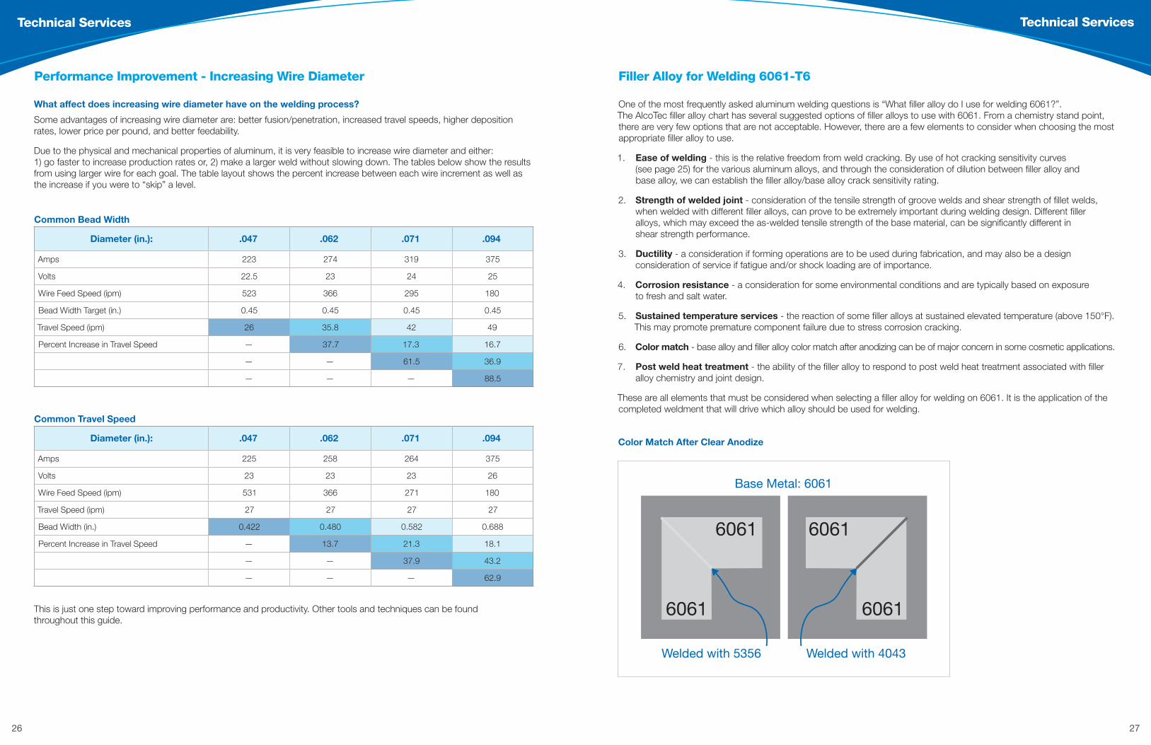
One of the most frequently asked aluminum welding questions is “What filler alloy do I use for welding 6061?”. The AlcoTec filler alloy chart has several suggested options of filler alloys to use with 6061. From a chemistry stand point, there are very few options that are not acceptable. However, there are a few elements to consider when choosing the most appropriate filler alloy to use.
1. Ease of welding - this is the relative freedom from weld cracking. By use of hot cracking sensitivity curves (see page 25) for the various aluminum alloys, and through the consideration of dilution between filler alloy and base alloy, we can establish the filler alloy/base alloy crack sensitivity rating.
2. Strength of welded joint - consideration of the tensile strength of groove welds and shear strength of fillet welds, when welded with different filler alloys, can prove to be extremely important during welding design. Different filler alloys, which may exceed the as-welded tensile strength of the base material, can be significantly different in shear strength performance.
3. Ductility - a consideration if forming operations are to be used during fabrication, and may also be a design consideration of service if fatigue and/or shock loading are of importance.
4. Corrosion resistance - a consideration for some environmental conditions and are typically based on exposure to fresh and salt water.
5. Sustained temperature services - the reaction of some filler alloys at sustained elevated temperature (above 150°F). This may promote premature component failure due to stress corrosion cracking.
6. Color match - base alloy and filler alloy color match after anodizing can be of major concern in some cosmetic applications.
7. Post weld heat treatment - the ability of the filler alloy to respond to post weld heat treatment associated with filler alloy chemistry and joint design.
These are all elements that must be considered when selecting a filler alloy for welding on 6061. It is the application of the completed weldment that will drive which alloy should be used for welding.
Filler Alloy for Welding 6061-T6
Color Match After Clear Anodize
6061 6061
60616061
Welded with 4043
Base Metal: 6061
Welded with 5356
� �
Performance Improvement - Increasing Wire Diameter
What affect does increasing wire diameter have on the welding process?
Some advantages of increasing wire diameter are: better fusion/penetration, increased travel speeds, higher deposition rates, lower price per pound, and better feedability.
Due to the physical and mechanical properties of aluminum, it is very feasible to increase wire diameter and either: 1) go faster to increase production rates or, 2) make a larger weld without slowing down. The tables below show the results from using larger wire for each goal. The table layout shows the percent increase between each wire increment as well as the increase if you were to “skip” a level.
Common Bead Width
Diameter (in.): .047 .062 .071 .094
Amps 223 274 319 375
Volts 22.5 23 24 25
Wire Feed Speed (ipm) 523 366 295 180
Bead Width Target (in.) 0.45 0.45 0.45 0.45
Travel Speed (ipm) 26 35.8 42 49
Percent Increase in Travel Speed — 37.7 17.3 16.7
— — 61.5 36.9
— — — 88.5
Common Travel Speed
Diameter (in.): .047 .062 .071 .094
Amps 225 258 264 375
Volts 23 23 23 26
Wire Feed Speed (ipm) 531 366 271 180
Travel Speed (ipm) 27 27 27 27
Bead Width (in.) 0.422 0.480 0.582 0.688
Percent Increase in Travel Speed — 13.7 21.3 18.1
— — 37.9 43.2
— — — 62.9
This is just one step toward improving performance and productivity. Other tools and techniques can be found throughout this guide.
28 29
Technical Services Technical Services
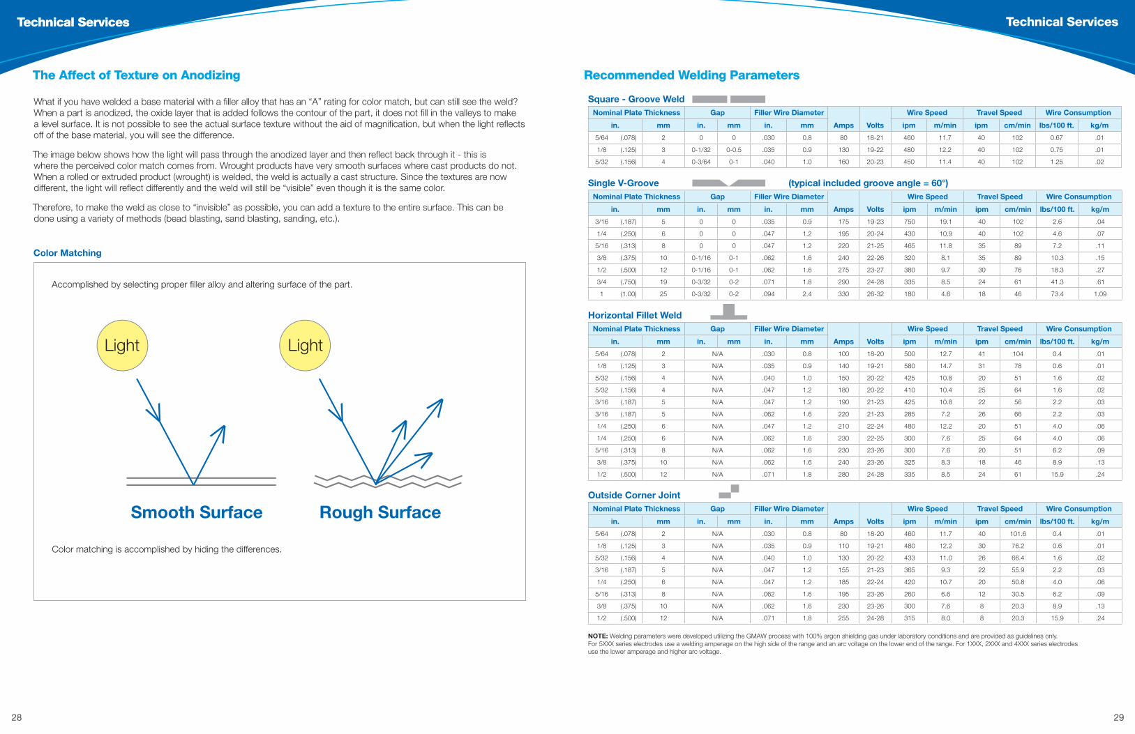
Recommended Welding Parameters
FIND US facebook.com/alcotecwire
AlcoTec Wire Corporation / alcotec.com / 1.800.228.0750
2750 Aero Park Drive, Traverse City, MI 49686-9263
ALC
-100
37 0
4/14
Recommended Welding Parameters
Square - Groove WeldNominal Plate Thickness Gap Filler Wire Diameter
Amps Volts
Wire Speed Travel Speed Wire Consumption
in. mm in. mm in. mm ipm m/min ipm cm/min lbs/100 ft. kg/m
5/64 (.078) 2 0 0 .030 0.8 80 18-21 460 11.7 40 102 0.67 .01
1/8 (.125) 3 0-1/32 0-0.5 .035 0.9 130 19-22 480 12.2 40 102 0.75 .01
5/32 (.156) 4 0-3/64 0-1 .040 1.0 160 20-23 450 11.4 40 102 1.25 .02
Single V-Groove (typical included groove angle = 60°)Nominal Plate Thickness Gap Filler Wire Diameter
Amps Volts
Wire Speed Travel Speed Wire Consumption
in. mm in. mm in. mm ipm m/min ipm cm/min lbs/100 ft. kg/m
3/16 (.187) 5 0 0 .035 0.9 175 19-23 750 19.1 40 102 2.6 .04
1/4 (.250) 6 0 0 .047 1.2 195 20-24 430 10.9 40 102 4.6 .07
5/16 (.313) 8 0 0 .047 1.2 220 21-25 465 11.8 35 89 7.2 .11
3/8 (.375) 10 0-1/16 0-1 .062 1.6 240 22-26 320 8.1 35 89 10.3 .15
1/2 (.500) 12 0-1/16 0-1 .062 1.6 275 23-27 380 9.7 30 76 18.3 .27
3/4 (.750) 19 0-3/32 0-2 .071 1.8 290 24-28 335 8.5 24 61 41.3 .61
1 (1.00) 25 0-3/32 0-2 .094 2.4 330 26-32 180 4.6 18 46 73.4 1.09
Horizontal Fillet WeldNominal Plate Thickness Gap Filler Wire Diameter
Amps Volts
Wire Speed Travel Speed Wire Consumption
in. mm in. mm in. mm ipm m/min ipm cm/min lbs/100 ft. kg/m
5/64 (.078) 2 N/A .030 0.8 100 18-20 500 12.7 41 104 0.4 .01
1/8 (.125) 3 N/A .035 0.9 140 19-21 580 14.7 31 78 0.6 .01
5/32 (.156) 4 N/A .040 1.0 150 20-22 425 10.8 20 51 1.6 .02
5/32 (.156) 4 N/A .047 1.2 180 20-22 410 10.4 25 64 1.6 .02
3/16 (.187) 5 N/A .047 1.2 190 21-23 425 10.8 22 56 2.2 .03
3/16 (.187) 5 N/A .062 1.6 220 21-23 285 7.2 26 66 2.2 .03
1/4 (.250) 6 N/A .047 1.2 210 22-24 480 12.2 20 51 4.0 .06
1/4 (.250) 6 N/A .062 1.6 230 22-25 300 7.6 25 64 4.0 .06
5/16 (.313) 8 N/A .062 1.6 230 23-26 300 7.6 20 51 6.2 .09
3/8 (.375) 10 N/A .062 1.6 240 23-26 325 8.3 18 46 8.9 .13
1/2 (.500) 12 N/A .071 1.8 280 24-28 335 8.5 24 61 15.9 .24
Outside Corner JointNominal Plate Thickness Gap Filler Wire Diameter
Amps Volts
Wire Speed Travel Speed Wire Consumption
in. mm in. mm in. mm ipm m/min ipm cm/min lbs/100 ft. kg/m
5/64 (.078) 2 N/A .030 0.8 80 18-20 460 11.7 40 101.6 0.4 .01
1/8 (.125) 3 N/A .035 0.9 110 19-21 480 12.2 30 76.2 0.6 .01
5/32 (.156) 4 N/A .040 1.0 130 20-22 433 11.0 26 66.4 1.6 .02
3/16 (.187) 5 N/A .047 1.2 155 21-23 365 9.3 22 55.9 2.2 .03
1/4 (.250) 6 N/A .047 1.2 185 22-24 420 10.7 20 50.8 4.0 .06
5/16 (.313) 8 N/A .062 1.6 195 23-26 260 6.6 12 30.5 6.2 .09
3/8 (.375) 10 N/A .062 1.6 230 23-26 300 7.6 8 20.3 8.9 .13
1/2 (.500) 12 N/A .071 1.8 255 24-28 315 8.0 8 20.3 15.9 .24
NOTE: Welding parameters were developed utilizing the GMAW process with 100% argon shielding gas under laboratory conditions and are provided as guidelines only. For 5XXX series electrodes use a welding amperage on the high side of the range and an arc voltage on the lower end of the range. For 1XXX, 2XXX and 4XXX series electrodes use the lower amperage and higher arc voltage.
What if you have welded a base material with a filler alloy that has an “A” rating for color match, but can still see the weld? When a part is anodized, the oxide layer that is added follows the contour of the part, it does not fill in the valleys to make a level surface. It is not possible to see the actual surface texture without the aid of magnification, but when the light reflects off of the base material, you will see the difference.
The image below shows how the light will pass through the anodized layer and then reflect back through it - this is where the perceived color match comes from. Wrought products have very smooth surfaces where cast products do not. When a rolled or extruded product (wrought) is welded, the weld is actually a cast structure. Since the textures are now different, the light will reflect differently and the weld will still be “visible” even though it is the same color.
Therefore, to make the weld as close to “invisible” as possible, you can add a texture to the entire surface. This can be done using a variety of methods (bead blasting, sand blasting, sanding, etc.).
The Affect of Texture on Anodizing
Color Matching
Technical Services
Accomplished by selecting proper filler alloy and altering surface of the part.
Color matching is accomplished by hiding the differences.
Aluminum Filler Alloy ChartBase Alloys Filler Alloys1060 10701080 1350
110020142036
2219 3003 300450055050
505250835456
50865056
511.0 512.0513.0 514.05154 5254
5454
6005 60606063 61016151 6351
6951
60616070
7005 70217039 7046710.0 711.0
413.0 443.0444.0 356.0
A356.0 A357.0359.0
319.0 333.0354.0 355.0
C355.0 380.0
Characteristics W S D C T M W S D C T M W S D C T M W S D C T M W S D C T M W S D C T M W S D C T M W S D C T M W S D C T M W S D C T M W S D C T M W S D C T M W S D C T M W S D C T M W S D C T M W S D C T M W S D C T M
319.0 333.0 354.0355.0 C355.0 380.0
2319* B A A A A B A A A A 2319*4043/4047* A C B A A A C B A A C D C D A C D C D A A C B A A A C B A A A C B A A A C B A A A C B A A A C B A A A C B A A A B A A A C B A A C 4043/4047*
4009* B B A A A B B A A A B C B C A B C B C A B B A B A B B A B A B B A B A B B A B A B B A B A B B A B A B B A B A B B A B A B B A A A A B B A A A A 4009*4145* A A B A A A A B A A A B C B A A B C B A A A B B A A A B B A A A B B A A A B B A A A B B A A A B A A B A A B B A B 4145*5554 A A A A A A A A A A A A A A B A A A A B A A A A B A A A A 5554
413.0 443.0 444.0 356.0 A356.0 A357.0
359.0
4043/4047* B B A A A B B A A A B B A A A B B A A A B B A A A A A A A A A A A A A A A A A A B B A A A B B A A A B B A A A A B A A A B 4043/4047*4145* A A B B A A A B B A A A B A A A A B A A A A B B A A A B B A A A B B A A A B B A A A B B A B 4145*4008* A A A A A A 4008*5554 5554
7005 70217039 7046710.0 711.0
4043/4047* A C C A A A C C A A B B A A A B B A A A A C C A A A D C B A A D C B A B D C B A A D C B A B D C B A 4043/4047*4145* A A B A A A A B A A 4145*5183 B A B A A B A B A A B A B A A B A B A A B A B A A A A B A A A A B A A A A B A A A A B A A A A B A A A A B A A A A B A A A A B A A 51835356 B B A A A B B A A A B B A A A B B A A A B B A A A A B A A A A B A A A A B A A A A B A A A A B A A A A B A A A A B A A A A B A A A 53565554 C C A A A A C C A A A A B C A A A A B C A A A B C A A A A B C A A A A B C A A A A B C A A A A 5554
5556 B A B A A B A B A A B A B A A B A B A A B A B A A A A B A A A A B A A A A B A A A A B A A A A B A A A A B A A A A B A A A A B A A 5556
5654 C C A A B C C A A A B C A A A B C A A A B C A A A B C A A A B C A A A B C A A A 5654
60616070
4043/4047* A E C A A A E C A A B B A A A B B A A A A E C A A A C A A A D C A A A D C A A A D C A A A C C A A 4043/4047*
4145* A D D B A A D D B A A A B A A A A B A A A D D B A A D D B A 4145*4643* A D C A A A C C A A 4643*5183 B A B A B A B A B A B A B A B A B A B A B A B A A A B A A A A B A A A A B B B A A B B B B A B B A B A B B B 51835356 B B A A B B A A B B A A B B A A B B A A B B A A A B A A A A B A A A A B A B A A B A B A B B A B A B B A B A 53565554 B C A B A B C A B A B C A B A B C A B A B C A B A B C A B A B C A B A B C A B A B C A A B B C A A A B C C A B B A C B A B B B 55545556 B A B A B A B A B A B A B A B A B A B A B A B A A A B A A A A B A A A A B B B A A B B B B A B B A B A B B B 5556
5654 C C A B A C C A B A B C A B A B C A B A B C A A A B C A A A C C A B B C B A B B 5654
6005 60606063 6101 6151 6351
6951
4043/4047* A E C A A A E C A A B B A A A B B A A A A E C A A A C A A A D C A A A D C A A A D C A A 4043/4047*4145* A D D B A A D D B A A A B A A A A B A A A D D B A A D D B A 4145*4643* A D C A A 4643*5183 B A B A B A B A B A B A B A B A B A B A B A B A A A B A A A A B A A B A B B A B A B B A B A B B A 51835356 B B A A B B A A B B A A B B A A B B A A B B A A A B A A A A B A A A B B A B A B B A B A B B A B A 53565554 B C A B A B C A B A B C A B A B C A B A B C A B A B C A B A B C A B A B C A B A C C A A A C C A A A A C C A B B A 55545556 B A B A B A B A B A B A B A B A B A B A B A B A A A B A A A A B A A B A B B A B A B B A B A B B A 55565654 C C A B A C C A B A B C A B A B C A B A C C A A B C C A B B C C A B B 5654
5454
5183 A A B B A A A B B A A A B B A A A B B A A A B B A A A B B A A A B B A A A B B A A A B B A A A B B A 51835356 A B A B A A B A B A A B A B A A B A B A A B A B A A B A B A A B A B A A B A B A A B A B A A B A B A 53565554 B C A A A A B C A A A A B C A A A A B C A A A A B C A A A A C C A A A A C C A A A C C A A A B C A A A B C A A A A 55545556 A A B B A A A B B A A A B B A A A B B A A A B B A A A B B A A A B B A A A B B A A A B B A A A B B A 55565654 B C A B A B C A B A B C A B A B C A B A B C A B A 5654
511.0 512.0 513.0 514.0
5154 5254
5183 A A B B A A A B B A A A B B A A A B B A A A B B A A A B B B A A B A A A A B A A A A B B B 51835356 A B A B A A B A B A A B A B A A B A B A A B A B A A B A B A A B A A A A B A A A A B A B A 53565554 B C A A A B C A A A B C A A A B C A A A B C A A A C C A A B B C A A A B C A A A B C A A B 55545556 A A B B A A A B B A A A B B A A A B B A A A B B A A A B B B A A B A A A A B A A A A B B A 55565654 B C A A B B C A A B B C A A B B C A A B B C A A B B C A A A B C A A B B C A A B B C A A A 5654
5086 5056
51835356555455565654
A A B A A A A B A A A A B A A A A B A A A A B A A A A B A A A A B A A A A B A A 5183A B A A A A B A A A A B A A A A B A A A A B A A A A B A A A A B A A A A B A A A 5356
C C A A A 5554A A B A A A A B A A A A B A A A A B A A A A B A A A A B A A A A B A A A A B A A 5556
B C A A B 5654
5083 5456
5183 A A B A A A A B A A A A B A A A A B A A A A B A A A A B A A A (3) B A A 51835356 A B A A A A B A A A A B A A A A B A A A A B A A A A B A A A A A A A 53565554 C C A A A 55545556 A A B A A A A B A A A A B A A A A B A A A A B A A A A B A A A A B A A 55565654 B C A A B 5654
5052
4043/4047* A C C A A A C C A A A C C A A A C C A A A C C A A A D C B A 4043/4047*5183 B A B A B A B A B A B A B A B A B A B A A A B C B 51835356 B B A A B B A A B B A A B B A A B B A A A B A C A 53565554 C C A A A B 55545556 B A B A B A B A B A B A B A B A B A B A A A B C B 55565654 B C A B A 5654
5005 5050
1100 C E A A A A C E A A A A C A A A A B A A A A 11004043/4047* A D D A A A D D A A A D D A A A C C A A A C D A A 4043/4047*
4145* B C E B A B C E B A B C E B A 4145*5183 C A C B C A C B C A C C B B A B A B A C B 51835356 C B B B C B B B C B B C B B B A A B B B B 53565556 C A C B C A C B C A C C B B A B A B A C B 5556
3004
1100 D E A A A A D E A A A A D A A A A 11004043/4047* A D D A A A D D A A A D D A A A D D A A 4043/4047*
4145* B C E B A B C E B A B C E B A 4145*5183 C A C B C A C B C A C B B A C C A 51835356 C B B B C B B B C B B B B B B C A 53565554 C C A B A A 55545556 C A C B C A C B C A C B B A C C A 5556
3003
1100 C C A A A A C C A A A A C A A A A 1100
4043/4047* B B B A A B B B A A B B A A A B B A A A B B B A A 4043/4047*
4145* A A C B A A A C B A A A B A A A A B A A A A C B A 4145*
22192319* B A A A A A A A A A A A 2319*
4043/4047* B B A A A B B A A A B C B C A C B C A 4043/4047*4145* A A B A A A A B A A A B C B A B C B A 4145*
2014 20362319* C A A A A A 2319*
4043/4047* B B A A A B B A A A B C B C A 4043/4047*4145* A A B A A A A B A A A B C B A 4145*
11001100 B B A A A A B B A A A A 1100
4043/4047* A A B A A A A B A A 4043/4047*
1060 10701080 1350
1100 B B A A A B 1100
1188 C C A A A A 11884043/4047* A A B A A 4043/4047*
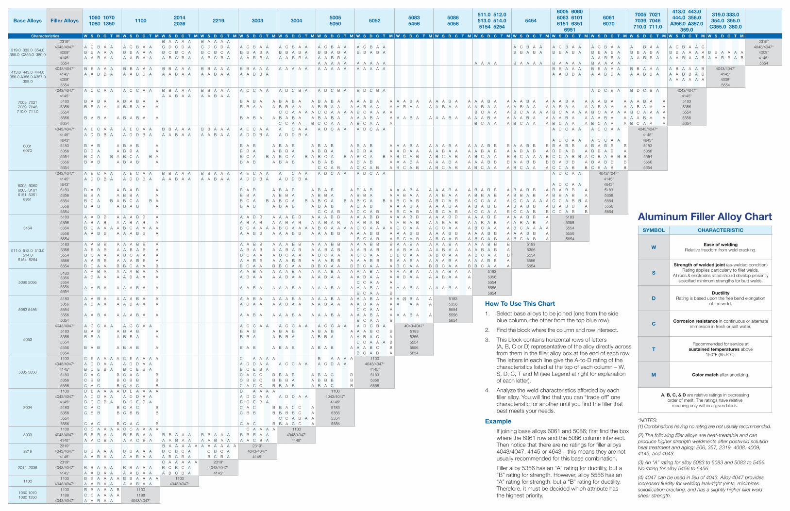
SYMBOL CHARACTERISTIC
W Ease of welding Relative freedom from weld cracking.
S
Strength of welded joint (as-welded condition)Rating applies particularly to fillet welds.
All rods & electrodes rated should develop presently specified minimum strengths for butt welds.
DDuctility
Rating is based upon the free bend elongation of the weld.
C Corrosion resistance in continuous or alternate immersion in fresh or salt water.
TRecommended for service at
sustained temperatures above150°F (65.5°C).
M Color match after anodizing.
A, B, C, & D are relative ratings in decreasingorder of merit. The ratings have relative
meaning only within a given block.
Aluminum Filler Alloy Chart
How To Use This Chart
1. Select base alloys to be joined (one from the side blue column, the other from the top blue row).
2. Find the block where the column and row intersect.
3. This block contains horizontal rows of letters (A, B, C or D) representative of the alloy directly across from them in the filler alloy box at the end of each row. The letters in each line give the A-to-D rating of the characteristics listed at the top of each column – W, S, D, C, T and M (see Legend at right for explanation of each letter).
4. Analyze the weld characteristics afforded by each filler alloy. You will find that you can “trade off” one characteristic for another until you find the filler that best meets your needs.
Example
If joining base alloys 6061 and 5086; first find the box where the 6061 row and the 5086 column intersect. Then notice that there are no ratings for filler alloys 4043/4047, 4145 or 4643 – this means they are not usually recommended for this base combination.
Filler alloy 5356 has an “A” rating for ductility, but a “B” rating for strength. However, alloy 5556 has an “A” rating for strength, but a “B” rating for ductility. Therefore, it must be decided which attribute has the highest priority.
*NOTES: (1) Combinations having no rating are not usually recommended.
(2) The following filler alloys are heat-treatable and can produce higher strength weldments after postweld solution heat treatment and aging: 206, 357, 2319, 4008, 4009, 4145, and 4643.
(3) An “A” rating for alloy 5083 to 5083 and 5083 to 5456. No rating for alloy 5456 to 5456.
(4) 4047 can be used in lieu of 4043. Alloy 4047 provides increased fluidity for welding leak-tight joints, minimizes solidification cracking, and has a slightly higher fillet weld shear strength. A
LC-1
0016
C 0
3/15

33
Education
School for aluminum welding. Aluminum welding is a specialized process. Whether you are transitioning from welding other materials, or you are a seasoned veteran, it is always important to understand the latest technologies and best practices. That is why we have developed a range of services to help improve your welding and your bottom line that are available at the AlcoTec facility – or we’ll come to you.
AlcoTec Weld School: Aluminum Welding Technology Theory & Practice – an international program that provides a hands-on approach to welding aluminum alloys
Welder Qualification Program
Welder training
On-site tailored consulting – assisting in the methodology and process of your application
Weld procedure development via tailored support or Welding Procedure Specifications (WPS)
Training and certification AlcoTec’s Weld School program is designed to incorporate both the theoretical and practical, hands-on approach to the welding of aluminum alloys. The classroom instruction includes an understanding of the theory and general characteristics of the various aluminum alloys and tempers.
Register online at alcotec.com/weldschool.
“AlcoTec has a very good quality product. They stand behind it.” – Joseph Maino, AlcoTec customer
Education
34 35
Education Education
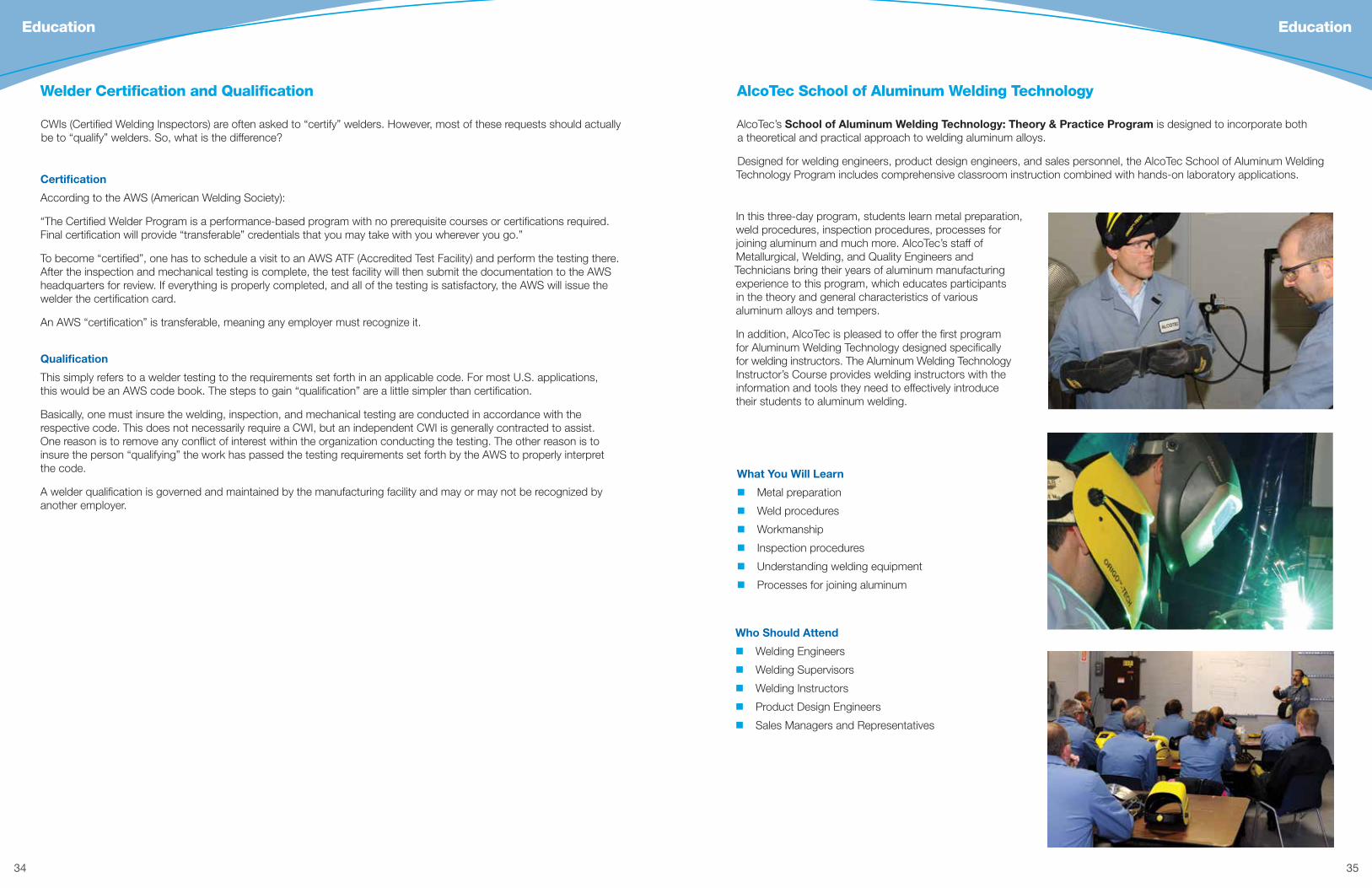
AlcoTec’s School of Aluminum Welding Technology: Theory & Practice Program is designed to incorporate both a theoretical and practical approach to welding aluminum alloys.
Designed for welding engineers, product design engineers, and sales personnel, the AlcoTec School of Aluminum Welding Technology Program includes comprehensive classroom instruction combined with hands-on laboratory applications.
AlcoTec School of Aluminum Welding Technology
What You Will Learn
Metal preparation
Weld procedures
Workmanship
Inspection procedures
Understanding welding equipment
Processes for joining aluminum
Who Should Attend
Welding Engineers
Welding Supervisors
Welding Instructors
Product Design Engineers
Sales Managers and Representatives
In this three-day program, students learn metal preparation, weld procedures, inspection procedures, processes for joining aluminum and much more. AlcoTec’s staff of Metallurgical, Welding, and Quality Engineers and Technicians bring their years of aluminum manufacturing experience to this program, which educates participants in the theory and general characteristics of various aluminum alloys and tempers.
In addition, AlcoTec is pleased to offer the first program for Aluminum Welding Technology designed specifically for welding instructors. The Aluminum Welding Technology Instructor’s Course provides welding instructors with the information and tools they need to effectively introduce their students to aluminum welding.
CWIs (Certified Welding Inspectors) are often asked to “certify” welders. However, most of these requests should actually be to “qualify” welders. So, what is the difference?
Welder Certification and Qualification
Qualification
This simply refers to a welder testing to the requirements set forth in an applicable code. For most U.S. applications, this would be an AWS code book. The steps to gain “qualification” are a little simpler than certification.
Basically, one must insure the welding, inspection, and mechanical testing are conducted in accordance with the respective code. This does not necessarily require a CWI, but an independent CWI is generally contracted to assist. One reason is to remove any conflict of interest within the organization conducting the testing. The other reason is to insure the person “qualifying” the work has passed the testing requirements set forth by the AWS to properly interpret the code.
A welder qualification is governed and maintained by the manufacturing facility and may or may not be recognized by another employer.
Certification
According to the AWS (American Welding Society):
“The Certified Welder Program is a performance-based program with no prerequisite courses or certifications required. Final certification will provide “transferable” credentials that you may take with you wherever you go.”
To become “certified”, one has to schedule a visit to an AWS ATF (Accredited Test Facility) and perform the testing there. After the inspection and mechanical testing is complete, the test facility will then submit the documentation to the AWS headquarters for review. If everything is properly completed, and all of the testing is satisfactory, the AWS will issue the welder the certification card.
An AWS “certification” is transferable, meaning any employer must recognize it.
alcotec.com | 1.800.228.0750A member of the ESAB Group, Inc.
Your aluminum partner.To learn more about what AlcoTec can do for you, call 1.800.228.0750 or visit alcotec.com.
AlcoTec Wire Corporation2750 Aero Park DriveTraverse City, MI 49686-9263
facebook.com/alcotecwire
ALC
-100
29C
05
/15
36
Education
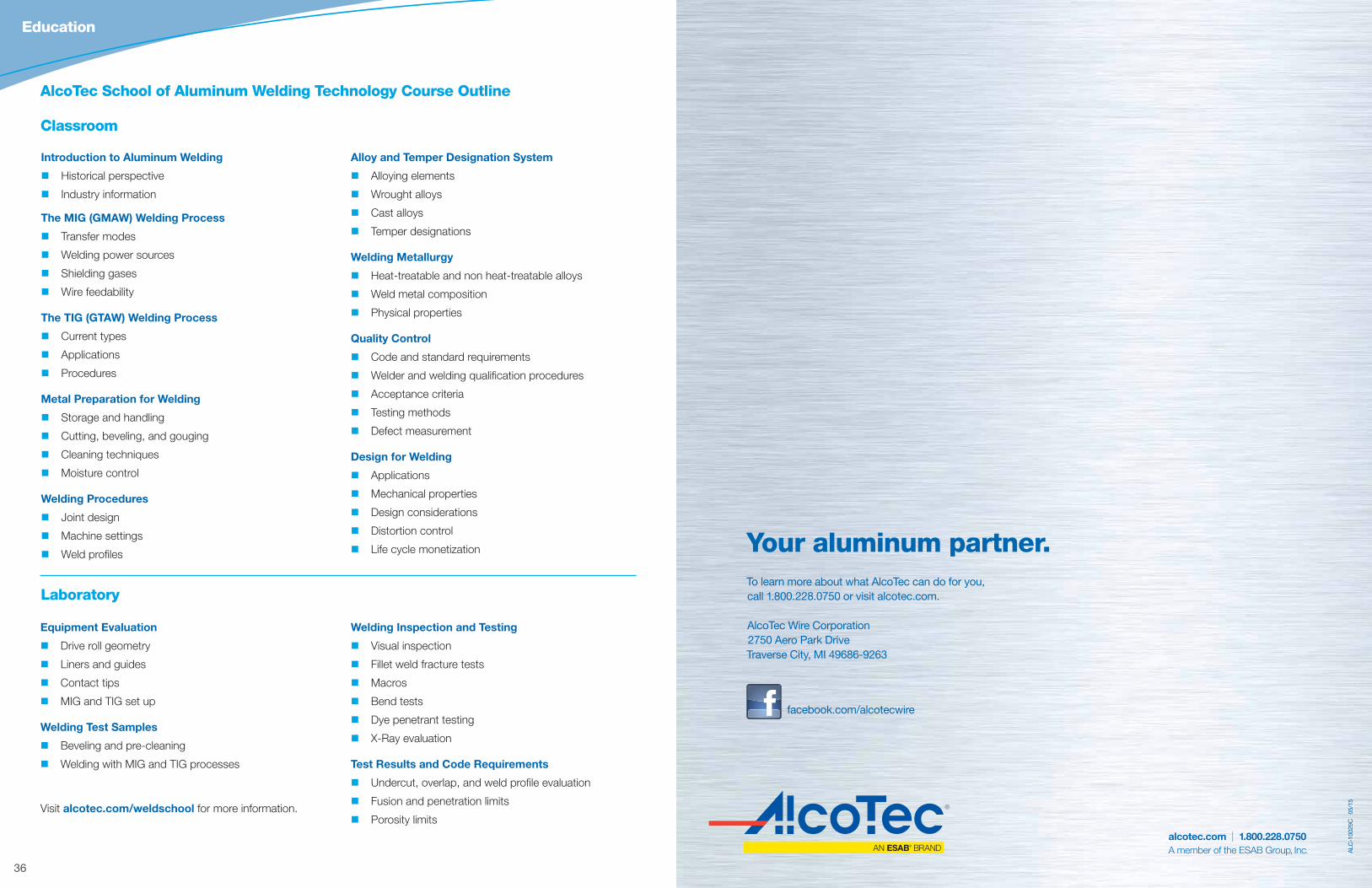
Classroom
Laboratory
AlcoTec School of Aluminum Welding Technology Course Outline
Introduction to Aluminum Welding
Historical perspective
Industry information
The MIG (GMAW) Welding Process
Transfer modes
Welding power sources
Shielding gases
Wire feedability
The TIG (GTAW) Welding Process
Current types
Applications
Procedures
Metal Preparation for Welding
Storage and handling
Cutting, beveling, and gouging
Cleaning techniques
Moisture control
Welding Procedures
Joint design
Machine settings
Weld profiles
Alloy and Temper Designation System
Alloying elements
Wrought alloys
Cast alloys
Temper designations
Welding Metallurgy
Heat-treatable and non heat-treatable alloys
Weld metal composition
Physical properties
Quality Control
Code and standard requirements
Welder and welding qualification procedures
Acceptance criteria
Testing methods
Defect measurement
Design for Welding
Applications
Mechanical properties
Design considerations
Distortion control
Life cycle monetization
Equipment Evaluation
Drive roll geometry
Liners and guides
Contact tips
MIG and TIG set up
Welding Test Samples
Beveling and pre-cleaning
Welding with MIG and TIG processes
Welding Inspection and Testing
Visual inspection
Fillet weld fracture tests
Macros
Bend tests
Dye penetrant testing
X-Ray evaluation
Test Results and Code Requirements
Undercut, overlap, and weld profile evaluation
Fusion and penetration limits
Porosity limitsVisit alcotec.com/weldschool for more information.