truckin’ with aluminum - milwaukee area technical college · truckin’ with aluminum aluminum...
TRANSCRIPT

Truckin’ with AluminumAluminum Welding from A to Z
Zane MichaelChris Anderson

Outline
Aluminum Welding vs. Steel◦ Process differences
Aluminum Welding Process Features◦ Starting and Stopping
◦ Dual Pulse for Cosmetics
Wire Feeding: Push or Pull?◦ Anderson – case for push
◦ Zane – case for pull
Aluminum Trailer Production◦ Equipment considerations for larger structures
Robot Reach vs. More Robots
Wire delivery for mobile robots
Sensor selection

Aluminum vs. Steel - Basics
High Thermal Conductivity◦ Makes it difficult to get puddle to fuse at start(cold lap)◦ Heat travels along joint and “preheats” weld
Weld bead can widen if nothing else is changed
Low Melting Point◦ Once mat’l is heated it melts quickly◦ AL puddle is very fluid and can run quickly (esp. 4043)
Little color change between solid/liquid aluminum◦ Without red to orange color change in steel, it can be
difficult to judge how much heat is in AL part.
Fast Solidification Rate◦ Can often travel faster than steel◦ Rapid freezing of puddle leaves depression in crater

Aluminum Process Considerations
Arc Starting – Need to “burn in” at start◦ Hot Starting – Travel short distance with “Hot” settings
Steel uses dwell at start to build puddle, this will promote cold lap with AL
◦ Lift Starting – retracting wire with pull guns
Dual Pulse – Alternating Heat Settings at 2-5 Hz◦ Can produce GTAW like cosmetics with GMAW◦ Can balance Heat Input in long welds producing uniform bead width◦ May be power source or robot based; best when it includes a change in wire
feed speed to get high/low current settings
Arc Ending – Need more time to fill puddle◦ Will be at least 1 second and often more for larger welds◦ Two stage crater is advantageous for fill 1 and fill 2◦ Back stepping crater can help move depression from end of weld◦ Controlled burnback to minimize the ball (key to good start)
Travel Angle◦ 10-15 deg push angle promotes flat bead, reduces smut (steel=5-10 deg)◦ Faster freeze allows faster travel speeds

Arc Starting
High Thermal Conductivity◦ Makes it difficult to
get puddle to fuse at start(cold lap)
◦ Heat travels to thicker member and causes puddle to favor one side
Lack of fusion at toe of weld
Puddle favors upper leg

Arc Starting
Arc Starting – Need to “burn in” at start◦ Hot Starting – Travel
short distance with “Hot” settings
Steel uses dwell at start to build puddle, this will promote cold lap with AL
◦ Slope current– can gradually reduce heat (if supported)
Current
Motion
5-15 mm

Arc Starting
◦ Parameters can be balanced to minimize size of the start
Lift Starting –retracting wire with pull guns◦ Used to create more
stable arc start

Dual Pulse – TIG like cosmetics
Dual Pulse – Alternating Heat Settings at 2-5 Hz◦ Can produce GTAW like cosmetics with GMAW
◦ Can balance Heat Input in long welds producing uniform bead width
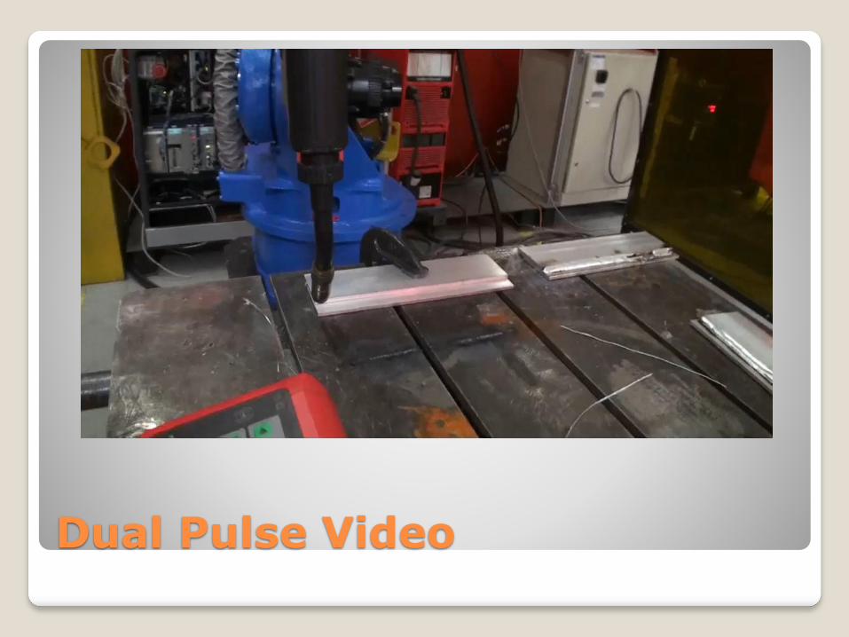
Dual Pulse Video

Frequency controls spacing
F = 2 Hz
F = 5 HzF = OFF

Power source or Robot based
Ref.

Sealed welds on tanks
Why did trucking customer reject welds?

Arc Ending – Fill the puddle
Arc Ending – Need more time to fill puddle◦ Will be at least 1 second
and often more for larger welds
◦ Two stage crater is advantageous for fill 1 and fill 2
◦ Back stepping crater can help move depression from end of weld
◦ Controlled burnback to minimize the ball (key to good start)

Arc End – Crater Fill
Single Step Crater Two Step Crater
Fill and slight depression
Fill1 and fill 2
Current< 100 Amps

Arc End
Arc End – Back Step Crater◦ Use heat of weld to
fuse end (dwell)
◦ Reverse direction a few mm and fill depression
◦ Reduces stress riser of crater
Current
Motion
5-15 mm
< 100 Amps
< weld current (Fill 1)
Dwell at End
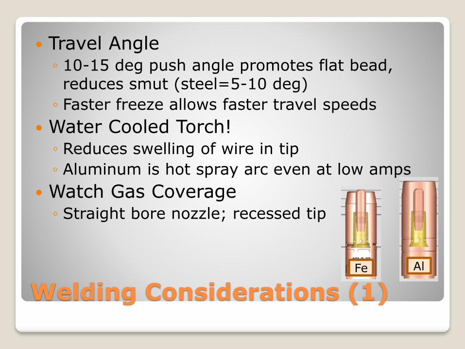
Welding Considerations (1)
Travel Angle◦ 10-15 deg push angle promotes flat bead, reduces smut (steel=5-10 deg)
◦ Faster freeze allows faster travel speeds
Water Cooled Torch!◦ Reduces swelling of wire in tip
◦ Aluminum is hot spray arc even at low amps
Watch Gas Coverage◦ Straight bore nozzle; recessed tip
Fe Al

Welding Considerations (2)
Clean Material◦ Oil and excessive oxide will result in soot and porosity
◦ Clean with Stainless Steel brushes
Use SS tooling details with Al, does not melt together
U shaped drive rolls for Al
Teflon or plastic consumables◦ Avoid sharp edges and breaks in feed
Brass jump liner at tip –helps w/heat
Reduce breaks in feed
system
Welding Considerations - Sensors
Touch Sensing◦ Possible with Aluminum, but softer wire may limit
search speeds due to bending
◦ Don’t use wire brake! Pull gun can keep wire in constant position
Through Arc Tracking◦ Not possible with current signal only
◦ Some manufacturers working on hybrid signals
Laser Sensors◦ Generally, most reliable sensor on Aluminum
◦ Need to evaluate surface condition and reflectivity
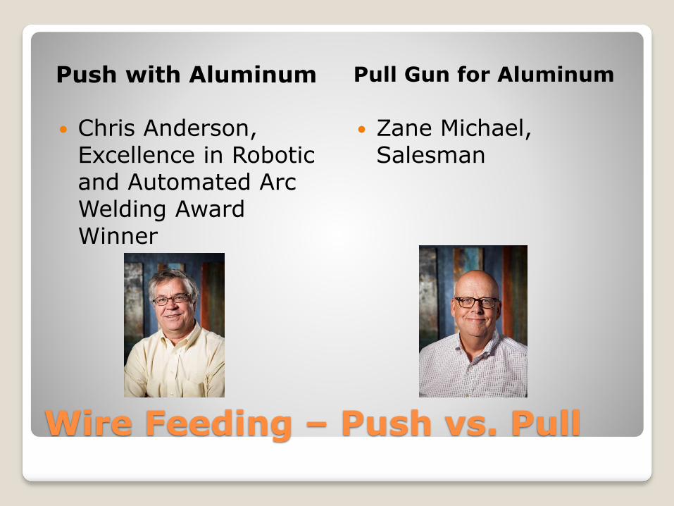
Wire Feeding – Push vs. Pull
Push with Aluminum Pull Gun for Aluminum
Chris Anderson, Excellence in Robotic and Automated Arc Welding Award Winner
Zane Michael, Salesman

GMT 800 Radiator Support
Push Only Experience
Largest robotic aluminum welding installation at a single site in North America
◦ More than 120 welding robots
◦ 35,000 parts/week with 90+ welds/part
◦ 3,000,000 arc starts per week with push-only feed system
◦ More than eight years of production
Push Only Feed w/WC torch
Feeder on upper arm
◦ Limit feed distance
Motorized bulk dereelers
Power Source with positive starting
◦ 2,000 arc start test in 1990’s

Push Feeding for aluminum
Introduction of Thru-Arm robots has shortened feed distance and reduced torch cable bends and flexing

Push Only Video
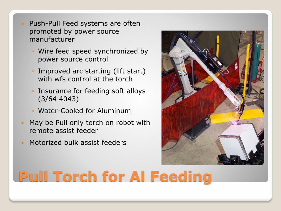
Pull Torch for Al Feeding
Push-Pull Feed systems are often promoted by power source manufacturer
◦ Wire feed speed synchronized by power source control
◦ Improved arc starting (lift start) with wfs control at the torch
◦ Insurance for feeding soft alloys (3/64 4043)
◦ Water-Cooled for Aluminum
May be Pull only torch on robot with remote assist feeder
Motorized bulk assist feeders

Push Pull Video

Push-Pull req’d for thin mat’l
Push-Pull can provide specialty capability for thin mat’l

Push-Pull for Thru-Arm Robots
Fronius Robacta Lincoln SA Aluminum
Best of Both Worlds

Key Factors for Truck Welding
Larger size parts to weld◦ Long reach robots; push pull consideration
◦ Multiple Robots; cover longer rail assemblies
◦ Robots on tracks; wire drum on carriage
Sensors; touch sensing or laser sensors.. NOT through arc
Examples of some layouts for Trailer Mfg.

Long Reach Robots for Trailers

Combine Sub-Ass’y, Final Ass’y

Bulk Trailer System
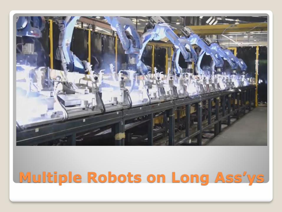
Multiple Robots on Long Ass’ys

Flat Bed Trailer snip-it

Bulk Wire Feed for Al
Pull Torch for Feed Assist Feeder for Bulk

Robot on Track = Tow Wire Drum
Trailer System 1 Trailer System 2

Laser Sensors for Aluminum
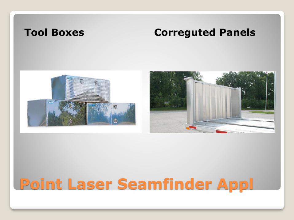
Point Laser Seamfinder Appl
Tool Boxes Correguted Panels
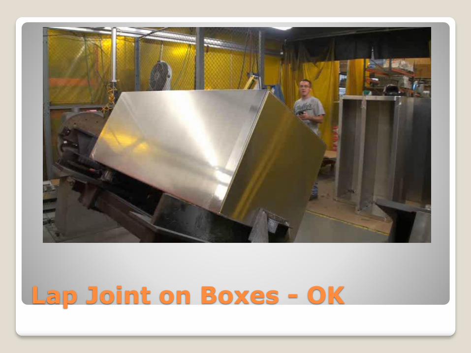
Lap Joint on Boxes - OK

Al Sheet Panel – Too Reflective