aircraft - very heavy lift at very low cost
TRANSCRIPT
Aircraft - Very Heavy Lift at Very Low Cost
Stephen Funck
This is a span loader for standard shipping containers. The design goal is the lowest cost per ton / mile. Low
wing loading allows for low flight speed, low power, low fuel per pound per mile, low altitude, non pressurized,
low construction cost. Existing configurations are unable to have the necessary
thick wing and great wing surface.
It is a tandem wing joined to an airfoil cargo carrier.This configuration and operation have no antecedents.
2
Containers and wing load
• Containers are measured in Twenty-foot Equivalent Units (TEU) 20 ft × 8 ft usually 8.5 ft high, average load 30,000 lb.
• The dimension for a one TEU wing is a 20 ft wingspan. Thickness at 10% of chord, results in a chord of 100 ft for 2,000 sq ft.
• That gives a wing load 15 lb / sq ft. The maximum airport wingspan, 80 meters, 260 ft, holds 13 TEU, 390,000 lb load.
• This value suggests there is potential for a very heavy lift aircraft with low wing load.
3
Potential
The initial target routes are third world with much higher rates than given below.
First world truck rates are near $.40 ton / mile. The ConcordLift™ 78 TEU version, at that rate, earns $275,000 in 8 hour, providing faster delivery at lower cost.
First world train rates are around $.10 ton / mile for unit trains. The ConcordLift™ 78 TEU version, at that rate, earns $70,000 in 8 hours, providing for many routes lower cost per TEU.
There are hundreds of millions of people in central Asia, Africa, Indonesia, the Philippines and elsewhere that have no access to low cost speedy transportation.
4
Potential
The initial target is high value or poorly served transportation markets, not highly competitive routes.
However:
2010 index cost (2TEU) across the Atlantic including port charges, fuel and all surcharges: East bound was $1810, and West bound $2520. The total time is over a week.
The ConcordLift™ 78 TEU version, at those rates, can earn $70,590 to $98,280 per trip. Making 5+ trips a week earns over $525,000 a week in a highly competitive market.
Five ConcordLift™ can deliver 3900 TEU in the same time as one container ship.
5
Potential
In 2010 there were 26 million TEU, with over 5 million in transit. Long distance is by slow ship or very expensive airfreight.
There should be a market in between.
Moving one percent would require 1000 ConcordLift™ aircraft.
• One runway, one 78 TEU ConcordLift™ every 5 minutes, 936 TEU per hour, 22,264 TEU per day. • The entire port of New York in 2010 handled 14,694 a day.• Ro-Ro ships can require one month's new car production to fill. • ConcordLift ™ can fly in ground effect and fly into continental interiors.
6
Unreachable
The standard configuration is unworkable because of the great length from nose to tail surfaces when the cord is 100 ft. A way must be found to shorten that distance.
A cord of 100 ft creates a strong venturi, low pressure, beneath the wing near the ground. A way must be found to minimize that so the aircraft can take off and land safely.
A cord of 100 ft and a span of 260 ft has a terrible aspect ratio, very high drag.
The obvious problems suggest the great potential is unreachable.
7
A Thought ExperimentConcordLift™ is a configurationThese are not engineering designs
In order to explain and illustrate, airfoils and other design features are shown. They were selected for convenience not because they are best.
The design issues are complex and quickly move into unknown areas. Considerable effort is needed to determine the actual potential of this configuration.
The first generation aircraft should be greatly improved in later generations.
8
Configuration and Benefits
ConcordLift ™ is a tandem wing aircraft without fuselage, with a cargo carrier airfoil pod.
The Tandem wings, auxiliary wings, are connected to the cargo pod by the vertical fins. They provide the lift needed for take off and enhance stability.
When the trailing edge of the pod is closest to the ground, the force of the venturi pulls it even closer. This makes flaps and ailerons problematical. The same occurs when one wingtip is closer to the ground.
9
Configuration and Benefits
The cargo airfoil must have the shortest distance between wing and ground at the center of lift. The goal is to obtain maximum lift and at the same time the least negative pressure between wing and ground.
Rotation, angle of attack, of the airfoil cargo pod is restricted and cannot develop adequate lift.
Flare is limited for landing.
10
Configuration and Benefits
The centers of lift of the tandem, auxiliary wings, balances on the center of lift of the cargo airfoil.
The illustrations for convenience show the centers of lift equally distant fore and aft of the cargo airfoil center of lift. The rear fins look out of place, too far forward.
The requirement is that the combined centers of lift match the combined centers of load.
11
The Cargo Carrier A very large, thick, spanloader cargo pod airfoil.
It cannot have flaps but can have leading edge slots and spoilers. Span up to 260 ft, the 80 meter box for large aircraft. A slow speed airfoil, thickness 10% of cord. If an inverted airfoil, the angle of attack is over 5° on the ground. At 150 ft chord, a 260 ft span can carry 20 53’ trailer bodies or 52 20’ containers in four rows from wing tip to wing tip. There have been many specialty airfoils proposed but never used. Some may be useful in this application.
12
The Cargo Carrier The center of the load, mid point of the channels, has to be at the
center of the lift. Each end of the container channel has a door, for fast loading
time. Between the container channels are trusses from wingtip to
wingtip. They are the wing spars. Those trusses combined with trusses above and below the container channels comprise a very strong wing box.
The shape of the airfoil is formed by a space frame. The carrier pod has great size and minimal weight.
13
Drag from boundary layer air The cargo carrier has very high boundary layer drag. There are a number of suggested ways for drag reduction that
have not been utilized in the past. They may be useful in this application.
Illustrated is a historic concept that claims a 30 to 70 % reduction.
It has been impractical to implement. Draw boundary layer inside the wing through perforations. The
interior is a plenum exhausted by fanjets.
14
Tandem Wings - Auxiliary Wings adjustable incidence
They are mounted on vertical fins fore and aft above the cargo wing. The fins carry tension, lift, from the tandem wings to the cargo wing.
Since they are fixed to fins at both ends, they have a suspension to absorb the turbulence cantilevered wings absorb by flexing.
They have pivots so the angle of attack can be changed. They provide rotation and flare, extra lift, needed at take
off and landing and have flaps and slots.
15
Wing Extensions
The main cargo pod might only be 100 ft wide, 5 TEU. Two 80 ft wings make a total 260 ft wingspan.
If 260 ft wide, extensions could fold like those for use on an aircraft carrier. The total flying width could be 700 ft with 220 ft extensions.
The total lift of the ConcordLift™ is not determined by the deep cord cargo wing portion alone.
Wings work together in harmony - “Concord” to accomplish what otherwise cannot be done.
16
Yaw, roll and pitch
At altitude, the ConcordLift ™ will turn and bank in the normal manner.
In ground effect, yaw is controlled by variation of engine power, spoilers automatically compensate for the increased lift of the outside wing, so turns can be with the wings level.
Pitch control for the cargo wing is provided by auxiliary wings.
17
Engines
Since prop wash over the top of the wing increases lift, many small engines might be an advantage.
On takeoff and landing, with the auxiliary wings set for maximum lift, the vector for drag will move higher. It may be necessary to mount some engines high on the fins so the thrust vector matches the drag vector.
Flights may last several days. Heavy, fuel efficient engines, could make for less total weight.
18
Landing gear
The force of the venturi beneath the cargo wing could be minimized with very long gear legs.
The following may be a better solution.
In addition to the normal main gear, have a set of “stabilizing gear”. The closer the cargo wing is to the ground the greater is the danger of instability.
The following is a “guess” at what might be sufficient. The “guess” is 10 ft is too short for safe landing.
19
Operation for landing and take off First contact with the ground is made by very large
diameter wheels on very long legs. The illustrations show a 30 ft height with 10 ft wheels.
Those stabilizing wheels carry a portion of the total load, the rest is carried by the lift, while the legs are controlled to descend to the main gear.
At take off, ConcordLift ™ lifts off from the main gear while the stabilizing gear, still in contact with the runway, carry a portion of the load.
The gear length is powered for the best AOA for take off and to level the aircraft for loading and unloading.
20
Operation for landing and take off ConcordLift™ has two separate take off speeds. The first is when it has enough lift to unload the weight on
the main gear. The aircraft begins to lift off while the rest of the weight is still carried on the stabilizing gear. As the distance between the ground and cargo wing increases, the force of the venturi in between is reduced.
The second is when the aircraft has developed enough lift to carry the total weight.
The heavy load is distributed over the total runway surface.
21
Operation for landing and take off
This complex two stage landing gear and process may appear unnecessary.
This aircraft changes altitude very slowly. It will spend a long time near the ground. Local instabilities will have time to develop great force between wing and surface.
An automated landing system is intended to make the proper counter actions.
At times local conditions will be less than ideal. The aircraft must always land and take off safely.
22
Operation for landing and take off
The main gear retracts into the cargo wing in front and in back of the cargo channels.
The stabilizing gear may be too large to retract inside the wing. It could retract into fairings under the wing.
Those fairings could have enough internal volume to serve as floats for ocean ditching.
Illustrations, documentation and animation of the take off procedure can be seen at www.concordlift.com.
23
Crew, Flight deck
Long distance flights will take several days. Several ConcordLift™ flying together could provide relief
for each other. Ground effect instabilities are self propagating and self
reinforcing. They require immediate management by automatic flight controls.
The base design should be able to fly and land without computerized flight control in smooth air over flat surface.
24
Crew, Flight deck
Automatic flight management control is intended to manage the multiple flight control surfaces in normal flight.
Automated landing and take off is also intended and is current state of the art for aircraft.
Storms move faster than ships and overtake ocean shipping. ConcordLift™ is faster than storms. Weather forecasting should prevent ConcordLift™ from being flown into dangerous weather.
25
Join for a better Aspect Ratio
The AR of a single ConcordLift ™ is poor. The very large wingtips of the cargo wing could enable
them to join together. A spanloader has no maximum wingspan.
Six ConcordLift ™ could have a combined AR of 10. Aircraft could take off separately, join up, cross the ocean,
and go to separate destinations.

26
Join for a better Aspect Ratio
The wingtip, 15 ft high, 150 ft long, or more is robust. It is able to make connection at the slow flying speed.
There are conceptual designs for this. Many different mechanisms could be designed. The small wing extensions of 30 ft cord and 3 ft thickness
might be tricky to join because of the small dimensions but the wind loads would also be less.
27
Manufacture
The main wing could be a space frame for great strength and flexibility with light weight at low cost.
Twenty 13 ft frames could be assembled into a 260 ft wide aircraft in 40 hours.
Wide and narrow cargo main wings could be made on the same assembly tool.
The only “new” items are the stabilizing gear and controls. They are well within current abilities.
Construction could be done with 1940’s technology.
28
So give me a picture already!
The ConcordLift ™ is a configuration that can be actualized in many ways. The following illustrate a few of them and some selected features.
In order to explain and illustrate an inverted airfoil and other design features are shown. The illustrations are by an artist.
Little has been attempted in aeronautical engineering. The design issues are complex and quickly move into unknown areas.
29
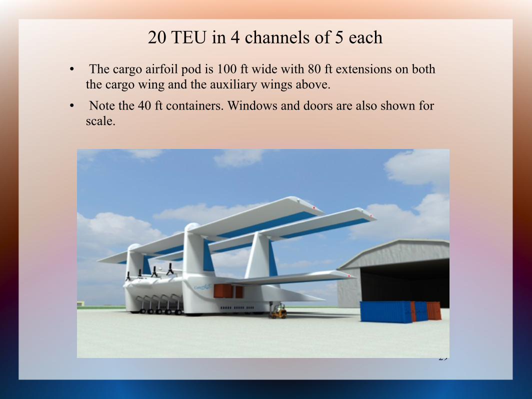
20 TEU in 4 channels of 5 each The cargo airfoil pod is 100 ft wide with 80 ft extensions on both
the cargo wing and the auxiliary wings above. Note the 40 ft containers. Windows and doors are also shown for
scale.
30
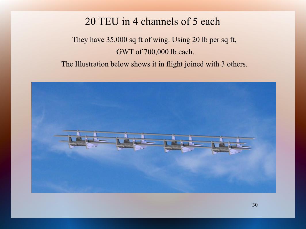
20 TEU in 4 channels of 5 eachThey have 35,000 sq ft of wing. Using 20 lb per sq ft,
GWT of 700,000 lb each. The Illustration below shows it in flight joined with 3 others.
31
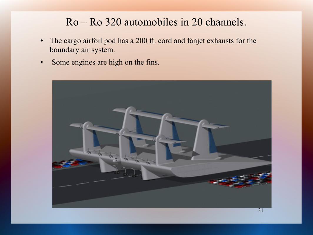
Ro – Ro 320 automobiles in 20 channels. The cargo airfoil pod has a 200 ft. cord and fanjet exhausts for the
boundary air system. Some engines are high on the fins.
32
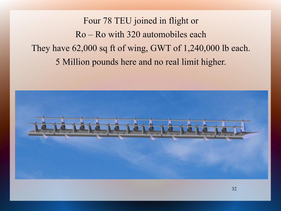
Four 78 TEU joined in flight orRo – Ro with 320 automobiles each
They have 62,000 sq ft of wing, GWT of 1,240,000 lb each. 5 Million pounds here and no real limit higher.
33
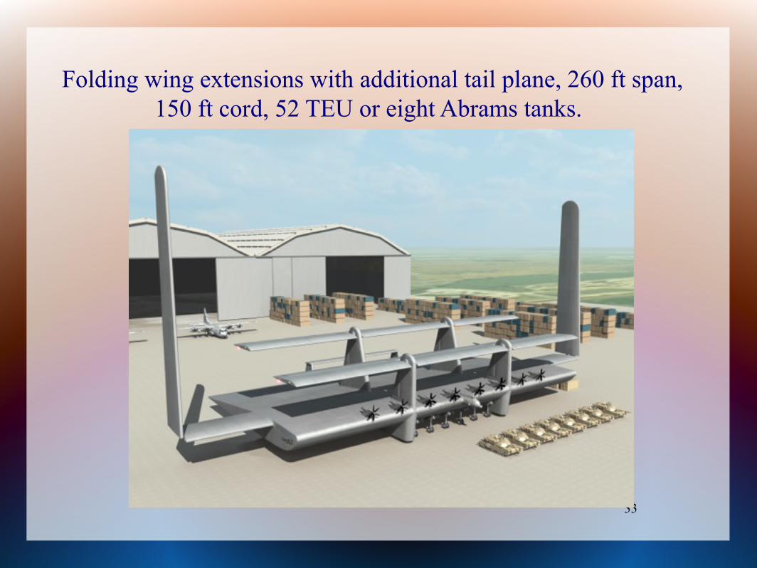
Folding wing extensions with additional tail plane, 260 ft span, 150 ft cord, 52 TEU or eight Abrams tanks.
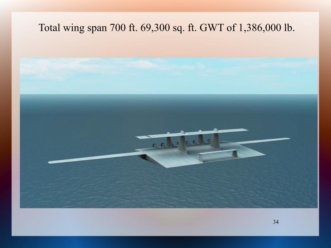
34
Total wing span 700 ft. 69,300 sq. ft. GWT of 1,386,000 lb.
35
Operational Use ConcordLift™ will fly slower and below commercial jet
traffic. It could remain in ground effect across the oceans and climb above coastal ranges to interior airports.
The initial concept is designed to fit on current large airport runways when there is no other traffic.
It is expected specialized container air ports will be built, similar to the specialized sea ports.
ConcordLift™ will reduce transportation cost providing good profits to the carrier.
It should sell at a good profit.
36
Other Developments
There are design concepts for ground handling tug. For use as an ocean patrol craft, there is a kind of “ships
boat” to provide the ability to place and retrieve personnel from the surface.
The three wings working together can be swept back and mated with a fuselage. They could provide high speed, high altitude, very high capacity, passenger service.
The concept for 1400 passengers is designed to make a complete turn around in a half hour.
37
Reason for name
There are no papers, or prior art, to reference that would increase understanding.
The essential features are: very deep cord wing, with auxiliary wings for control and the lift needed for take off and landing.
The name for this configuration is “ConcordLift™”, because the wings work in concord – harmony.
The name is specified in Patent Application #12/653,489.