air purification unit - apu -...
TRANSCRIPT
AIR PURIFICATION UNIT - APU
CARROLL MANUFACTURING INTERNATIONAL®
23 Vreeland Road, Florham Park, New Jersey 07932 • Phones (973) 966-6000, (800) 444-9696Fax (973) 966-0315 • Email: [email protected] • Website: www.carrollmi.com
GREASE, SMOKE, AND ODOR ABATEMENTFOR COMMERCIAL COOKING APPLICATIONS
— INSTALLATION & TECHNICAL MANUAL —
File # MH26289
1200 Fewster Drive, Mississauga, Ontario, Canada L4W 1A1 · Phone (905) 731-1050 Fax (905) 731-8547 · Email: [email protected] · Website: www.carrollmi.com
To Installing Contractors and End Users:
This Manual is for your guidance in the installation, maintenance, andtrouble-shooting of our EnvironAir APU Units. It is important that youbecome familiar with the Manual’s contents, and that you keep it in a cleanand safe place for future reference.
The equipment represented by this Manual is of the highest quality, and isof state-of-the-art design. Proper continued maintenance, however, isnecessary for continued effective performance.
If you have any questions about the goods represented by this Manual, orof our other Carroll lines of Foodservice Industry equipment, we would bepleased to hear from you.
Sincerely,
Carroll Manufacturing International®
23 Vreeland Road, Florham Park, New Jersey 07932Phone (973) 966-6000 Fax (973) 966-0315 Toll Free (800) 444-9696
Exhaust Systems • Utility Distribution Systems • Fire Protection • Heat Reclaim Units
1200 Fewster Drive, Mississauga, Ontario, Canada L4W 1A1 Phone (905) 731-1050 Fax (905) 731-8547
Exhaust Systems · Fire Protection · Heat Reclaim Units

- TABLE OF CONTENTS -
Page
General Unit Description and Operation . . . . . . . . . . . . . . . . . . . . . . . . . . . .1-5
Odor Spray Section . . . . . . . . . . . . . . . . . . . . . . . . . . . . . . . . . . . . . . . . . . . .6-9
Odor Abatement Process . . . . . . . . . . . . . . . . . . . . . . . . . . . . . . . . . . . . . .6
Control Cabinet Assembly . . . . . . . . . . . . . . . . . . . . . . . . . . . . . . . . . . . . . .7
Timers and Nozzle Assembly . . . . . . . . . . . . . . . . . . . . . . . . . . . . . . . . . .8-9
Odor Media Control Section . . . . . . . . . . . . . . . . . . . . . . . . . . . . . . . . . . . .9-11
Material Safety Data Sheets . . . . . . . . . . . . . . . . . . . . . . . . . . . . . . . . . . .12-17
Installation & Start-up . . . . . . . . . . . . . . . . . . . . . . . . . . . . . . . . . . . . . . . .18-19
EnvironAir Start Up Report (Operator Copy) . . . . . . . . . . . . . . . . . . . . . .20-21
Maintenance Instructions & Schedule . . . . . . . . . . . . . . . . . . . . . . . . . . .22-24
Trouble-Shooting . . . . . . . . . . . . . . . . . . . . . . . . . . . . . . . . . . . . . . . . . . . .25-27
Assembly Details & Parts Lists . . . . . . . . . . . . . . . . . . . . . . . . . . . . . . . . .28-31
Standard Wiring Diagrams . . . . . . . . . . . . . . . . . . . . . . . . . . . . . . . . . . . .32-35
EnvironAir Start-Up Report (Carroll Manufacturing Int’l. Copy) . . . . . . . .36-37
Warranty Statement . . . . . . . . . . . . . . . . . . . . . . . . . . . . . . . . . . . . . . . . . . . .38
Through our on-going program of product development, Carroll Manufacturing International® reservesthe right to alter the goods and the specification of the goods represented within this Manual
25-26
27-30
31-32
33-34
35
1
4567 3 2 1
ODORSPRAYCABINET
CHANNEL BASE
AIRFLOW
9
SOUNDPROOFING INSULATIONOPTIONAL
4867 3 2 1
CHANNEL BASE
AIRFLOW
9
SOUNDPROOFING INSULATIONOPTIONAL
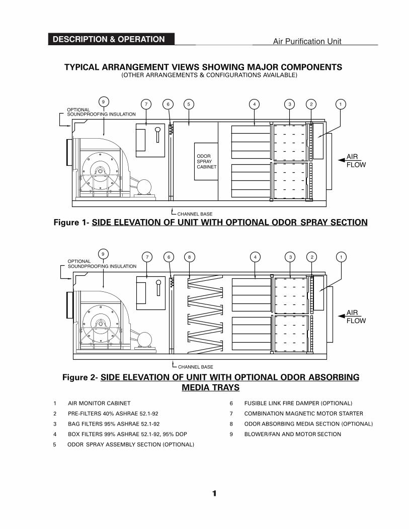
TYPICAL ARRANGEMENT VIEWS SHOWING MAJOR COMPONENTS (OTHER ARRANGEMENTS & CONFIGURA TIONS AV AILABLE)
Figure 1- SIDE ELEV A TION OF UNIT WITH OPTIONAL ODOR SPRAY SECTION
Figure 2- SIDE ELEV A TION OF UNIT WITH OPTIONAL ODOR ABSORBING
MEDIA TRA YS
1 A IR MONITOR CABINET
2 PRE-FILTERS 40% ASHRAE 52.1-92
3 BAG FILTERS 95% ASHRAE 52.1-92
4 BOX FILTERS 99% ASHRAE 52.1-92, 95% DOP
5 ODOR SPRAY ASSEMBLY SECTION (OPTIONAL)
6 FUSIBLE LINK FIRE DAMPER (OPTIONAL)
7 COMBINATION MAGNETIC MOTOR STARTER
8 ODOR ABSORBING MEDIA SECTION (OPTIONAL)
9 BLOWER/FAN AND MOTOR SECTION
1
DESCRIPTION & OPERATION Air Purification Unit

2
PRODUCT DESCRIPTION CODESCarroll EnvironAir APU’s are identified by a series of letters and numbers which designates features.
SERIAL DESIGNATION: 1.________ 2.________ 3.________ 4.________ 5.________ 6.________ Explanation of Codes:
1. Filter Section
APU..................The Basic Filter section which includes: Pre-Filter, Bag Filter, Box Filter, Fire Stat, Air Monitor Cabinet,Status Panel, and Filter Enclosure Cabinet/Housing with Fire Damper.
NAPU............... Includes all of the components of the APU model but the Fire Damper is omitted.2. Unit Size
APU Model CFM Range APU Model CFM Range APU Model CFM RangeNumber Number Number
01 500-1100 08 6100-8000 18 16100-1800002 1100-2000 09 8100-9000 20 18100-2000003 2100-3000 10 9100-10000 24 20100-2400004 3100-4000 12 10100-12000 28 24100-2800005 4100-5000 14 12100-14000 32 28100-3200006 5100-6000 15 14100-15000 36 32100-36000
16 15100-16000 40 36100-400003. Odor Abatement Option
OS ......................Odor spray with indoor style cabinet.HS ......................Heated/Insulated odor spray outdoor style cabinet.OT ......................Odor media trays filled with alumnia spheres impregnated with potassium permanganate or
activated carbon.4. Exhaust Fan Section
The “Standard” Fan Section includes a non-insulated (“FIN”) Indoor Fan Enclosure Cabinet, and Exhaust Fan (consists ofblower & motor), and a Combination Magnetic Motor Starter housed in a TYPE 1 General Purpose Indoor Cabinet.
FIN......................“Standard” Indoor Fan Section w/ No Sound Insulation Package and a Combination Magnetic MotorStarter housed in a TYPE 1 General Purpose Indoor Cabinet.
FIS ......................Optional Indoor Fan Section w/ Sound Insulation Package and a Combination Magnetic MotorStarter housed in a TYPE 1 General Purpose Indoor Cabinet.
FON....................Optional Outdoor Fan Section w/ No Sound Insulation Package and a Combination Magnetic MotorStarter housed in a TYPE 3R Raintight Outdoor Cabinet.
FOS ....................Optional Outdoor Fan Section w/ Sound Insulation Package and a Combination Magnetic MotorStarter housed in a TYPE 3R Raintight Outdoor Cabinet.
5. APU Status PanelACW ..................Is used in conjunction with a separately controlling fan circuit, and consists of the following: S/S
Cabinet, “Fan On” Light, “Low Air” Light, “Filter Out” Light, “Fire” Light, “Normal” Light, “Nil-Air”Light, “Reset” Momentary Push Button, “Control Bypass” Light, “Replace Pre-Filter” Light, “ReplaceBox-Filter” Light, “Replace Bag-Filter” Light, Relays, Timers, Control Transformer, and TerminalBlocks.
ACD....................Is used as a stand alone on/off fan control panel. This unit consists of the same parts as the ACWexcept the “Fan On” light is replaced with a “Fan On/Off” illuminated maintained Push Buttonswitch.
6. Hand-Off-Auto“H.O.A.” ............The H.O.A. is a manual selector control, built into the Magnetic Motor Starter Panel to turn the
exhaust fan on or off, by-passing the APU monitoring controls.
EXAMPLE: A (APU–10–OS–FIS–ACW-HOA) is a Carroll EnvironAir APU sized for 10,000 CFM nominal, with an indoor styleliquid odor spray section, a sound insulated indoor fan package, and a control panel for use with a separately controlling fancircuit, and a hand-off-auto option.
DESCRIPTION & OPERATION Air Purification Unit
Exhaust OutletEXHAUST INLET AND OUTLET MAY BE VERTICALLY UP,
AS SHOWN, OR HORIZONTALLY STRAIGHT THROUGH
OR HORIZONTALLY FROM THE LEFT OR RIGHT SIDE.
Exhaust Inlet
APU UNIT SHOWN IS WITH OPTIONAL
LIQUID ODOR SPRAY AND BLOWER SECTIONS.
Air MonitorCabinet
Filter Section
Odor Spray Cabinet Magnetic Motor
Starter Panel Blower/FanSection
ACW .......................... Is used in when the Fan Start signal is initiated from a remote mounted control panel such as a hood wash panel and consists of the following: S/S Cabinet, "Power On Lamp, “Fan On” Lamp, Replace Pre-Filter” Lamp, “Replace Bag-Filter” Lamp, Replace Box-Filter” Lamp, “Filter Out” Lamp, “Fire” Lamp, “Alarm Mute Push Button/Lamp, Relays, Timers, Control Transformer, and Terminal Blocks.
“H.O.A.” ....................The H.O.A. is a manual selector switch, built into the ACW or ACD control Panel. This option is generally used when BAS control is required and includes General Alarm and Critical Alarm monitoring signals for the BAS.
EXAMPLE: A (APU–10–OS–FIS–ACW-HOA) is a Carroll EnvironAir APU sized for 10,000 CFM nominal, with an indoor style liquid odor spray section, a sound insulated indoor fan package, and a control panel a with Hand-Off-Auto switch for use with a BAS or remote start/stop signal.

3
GENERAL DESCRIPTIONThe Carroll APU is a high efficiency air filtration system. It is a complete unit, including filters, optional odorabatement section, optional fire damper, and monitoring and operating controls. The unit may include anintegral exhaust fan section. Otherwise, it will be interconnected to an appropriate fan system provided byCarroll or others. It is Underwriters Laboratories (UL) Listed in both Canada and the United States, under thecategory “Hood and Duct Accessories.”
The units are located downstream from Grease Extractors or Hood and Filter Assemblies, and may be floormounted, suspended in a ceiling space, or outdoor roof mounted.
These units are designed as devices which will effectively and practically:
1. Remove residual airborne flammable particulates, grease, lint, dirt, and smoke from the exhaust airstream,allowing the discharge of kitchen exhaust at locations otherwise unacceptable. In Canada, all exhaustductwork downstream of the filter section can be of conventional non-welded design, rather than theheavy gauge, all welded ducts required by N.F.P.A. 96.
2. Provide means for periodic removal and replacement of air filters and odor removal media (whenemployed).
3. Arrest or otherwise prevent flame or hot gases produced under normal or abnormal conditions in thecooking area from entering the exhaust fan section and discharge duct system, by automatically closing afire damper should the air temperature become excessive. The fire damper is required in Canada and isoptional in the United States.
4. Be capable of containing combustion of contaminants within the unit following the fuse link activation ofthe fire damper.
5. Prevent the development of hazardous temperatures on combustible construction spaced 18-inches fromthe unit.
6. Fully abate or control odors below a nuisance level.
OPERATIONThe exhaust air, from either a high efficiency water wash grease extractor or a high efficiency dry greaseextractor, is ducted directly to the exhaust inlet of the APU. Grease, dust, lint, and smoke particles areremoved by then drawing the air through three increasingly efficient air filtering media sets. The first pass isthrough an array of 4” thick pleated media pre-filters. The second pass is through 95% efficient ASHRAE52.1-92 bag filters, UL/ULC CLASS 1. The third and final pass is through an array of 99% ASHRAE 52.1-92,95% DOP box filters, UL/ULC CLASS 1.
Thereafter, the air is standardly treated for odor control. Odor abatement with the Carroll EnvironAir® APU isaccomplished in one of three ways:
1. Neutralization by exposing the airstream to a chamber misted with EnvironSafe™ odor eliminator whichbreaks down the odor molecules into non-odorous compounds (water, carbon, nitrogen, etc.).
2. Oxidation of odor molecules by passing the airstream through an array of trays housing activated aluminaspheres impregnated with potassium permanganate.
3. Absorption/Adsorption of odor molecules by passing the airstream through an array of trays housingactivated carbon.
Note: A 50/50 blend of activated alumina spheres impregnated with potassium permanganate and activatedcarbon is also available.
A fusible-link fire damper is optionally located at the discharge of the filter section, or at the discharge of theoptional odor abatement section, to arrest or otherwise prevent flame or hot gases produced under normalor abnormal conditions in the cooking area from entering the exhaust fan section and discharge duct system,should the temperature at the fusible link exceed 212°F (100˚C). ONLY UL LISTED FUSIBLE LINKS STAMPEDWITH THIS TEMPERATURE ARE TO BE USED. THEY ARE TO BE INSPECTED SEMI-ANNUALLY, AND REPLACED ANNUALLY.
DESCRIPTION & OPERATION Air Purification Unit
4
DESCRIPTION & OPERATION
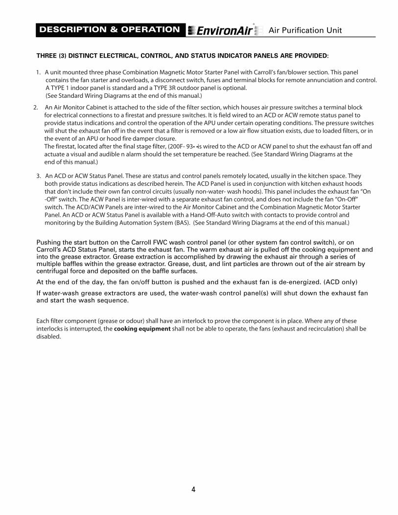
THREE (3) DISTINCT ELECTRICAL, CONTROL, AND STATUS INDICATOR PANELS ARE PROVIDED:
1. A unit sidewall-mounted three phase Combination Magnetic Motor Starter Panel, (provided only if theAPU is equipped with Carroll’s optional fan/blower section). This panel contains the fan starter andoverloads, a disconnect, fuses, control transformer, and terminal blocks for remote annunciation andcontrol. A TYPE 1 indoor panel is standard and a TYPE 3R outdoor panel is optional. (See Standard WiringDiagrams at the end of this manual.)
2. A unit sidewall-mounted Air Monitor Cabinet, which houses air pressure switches and a firestat. It isinterwired with an ACD or ACW remote status panel to provide status indications and control the operation ofthe APU under certain operating conditions. The pressure switches will shut the exhaust fan off in the eventthat a filter is removed or a Nil Air flow situation exists, due to loaded filters, or in the event of an APU orhood fire damper closure.
The firestat is set at 200˚F (93˚C), and is wired to the ACD or ACW panel to shut the exhaust fan off andactuate an alarm should the set temperature be reached. (See Standard Wiring Diagrams at the end ofthis manual.)
3. An ACD or ACW Status Panel. These are status and control panels remotely located, usually in the kitchenspace. They both provide status indications as described herein. The ACD Panel is used in conjunctionwith kitchen exhaust hoods that don't include their own fan control circuits (usually non-water- washhoods). This panel includes the exhaust fan “On-Off” switch. The ACW Panel is interwired with a separateexhaust fan control, and does not include the fan “On-Off” switch. The ACD/ACW Panels are interwired tothe Air Monitor Cabinet and the Combination Magnetic Motor Starter Panel. A deluxe ACD or ACW StatusPanel is available that provides contacts to the Building Monitor for the various functions of the APU. (SeeStandard Wiring Diagrams at the end of this manual.)
Pushing the start button on the Carroll FWC wash control panel (or other system fan control switch), or onCarroll’s ACD Status Panel, starts the exhaust fan. The warm exhaust air is pulled off the cooking equipment andinto the grease extractor. Grease extraction is accomplished by drawing the exhaust air through a series ofmultiple baffles within the grease extractor. Grease, dust, and lint particles are thrown out of the air stream bycentrifugal force and deposited on the baffle surfaces.
At the end of the day, the fan on/off button is pushed and the exhaust fan is de-energized. (ACD only)
If water-wash grease extractors are used, the water-wash control panel(s) will shut down the exhaust fanand start the wash sequence.
Air Purification Unit
1. A unit mounted three phase Combination Magnetic Motor Starter Panel with Carroll’s fan/blower section. This panel contains the fan starter and overloads, a disconnect switch, fuses and terminal blocks for remote annunciation and control. A TYPE 1 indoor panel is standard and a TYPE 3R outdoor panel is optional. (See Standard Wiring Diagrams at the end of this manual.)
2. An Monitor Cabinet is attached to the side of the filter section, which houses air pressure switches a terminal block for electrical connections to a firestat and pressure switches. It is field wired to an ACD or ACW remote status panel to provide status indications and control the operation of the APU under certain operating conditions. The pressure switches will shut the exhaust fan off in the event that a filter is removed or a low air flow situation exists, due to loaded filters, or in the event of an APU or hood fire damper closure. The firestat, located after the final stage filter, (200 F (93 C), and is wired to the ACD or ACW panel to shut the exhaust fan off and actuate a visual and audible n alarm should the set temperature be reached. (See Standard Wiring Diagrams at the end of this manual.)
3. An ACD or ACW Status Panel. These are status and control panels remotely located, usually in the kitchen space. They both provide status indications as described herein. The ACD Panel is used in conjunction with kitchen exhaust hoods that don't include their own fan control circuits (usually non-water- wash hoods). This panel includes the exhaust fan “On -Off” switch. The ACW Panel is inter-wired with a separate exhaust fan control, and does not include the fan “On-Off” switch. The ACD/ACW Panels are inter-wired to the Air Monitor Cabinet and the Combination Magnetic Motor Starter Panel. An ACD or ACW Status Panel is available with a Hand-Off-Auto switch with contacts to provide control and monitoring by the Building Automation System (BAS). (See Standard Wiring Diagrams at the end of this manual.)
2. An Air Monitor Cabinet is attached to the side of the filter section, which houses air pressure switches a terminal block for electrical connections to a firestat and pressure switches. It is field wired to an ACD or ACW remote status panel to provide status indications and control the operation of the APU under certain operating conditions. The pressure switches will shut the exhaust fan off in the event that a filter is removed or a low air flow situation exists, due to loaded filters, or in the event of an APU or hood fire damper closure. The firestat, located after the final stage filter, (200F- 93• • is wired to the ACD or ACW panel to shut the exhaust fan off and actuate a visual and audible n alarm should the set temperature be reached. (See Standard Wiring Diagrams at the end of this manual.)
Each filter component (grease or odour) shall have an interlock to prove the component is in place. Where any of these interlocks is interrupted, the cooking equipment shall not be able to operate, the fans (exhaust and recirculation) shall be disabled.
5
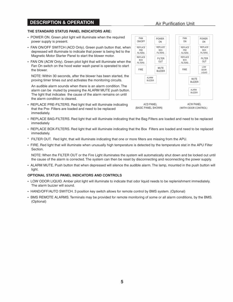
THE STANDARD STATUS PANEL INDICATORS ARE:
• POWER ON. Green pilot light will illuminate when the required power supply is present.
• FAN ON/OFF SWITCH (ACD Only). Green push button that, when depressed will illuminate to indicate that power is being fed to the Magnetic Motor Starter Panel to start the blower motor.
• FAN ON (ACW Only). Green pilot light that will illuminate when the Fan On switch on the hood water wash panel is operated to start the blower.
NOTE: Within 30 seconds, after the blower has been started, the proving timer times out and activates the monitoring circuits.
An audible alarm sounds when there is an alarm condition. The alarm can be muted by pressing the ALARM MUTE push button. The light that indicates the cause of the alarm remains on until the alarm condition is cleared.
• REPLACE PRE-FILTERS. Red light that will illuminate indicating that the Pre- Filters are loaded and need to be replaced immediately.
• REPLACE BAG-FILTERS. Red light that will illuminate indicating that the Bag Filters are loaded and need to be replaced immediately
• REPLACE BOX-FILTERS. Red light that will illuminate indicating that the Box Filters are loaded and need to be replaced immediately.
* FILTER OUT. Red light, that will illuminate indicating that one or more filters are missing from the APU.
• FIRE. Red light that will illuminate when unusually high temperature is detected by the temperature stat in the APU Filter Section.
NOTE: When the FILTER OUT or the Fire Light illuminates the system will automatically shut down and be locked out until the cause of the alarm is corrected. The system can then be reset by disconnecting and reconnecting the power supply.
• ALARM MUTE. Push button that when depressed will silence the audible alarm. The lamp, mounted in the push button will light.
OPTIONAL STATUS PANEL INDICATORS AND CONTROLS
• LOW ODOR LIQUID. Amber pilot light will illuminate to indicate that odor liquid needs to be replenishment immediately. The alarm buzzer will sound.
• HAND/OFF/AUTO SWITCH. 3 position key switch allows for remote control by BMS system. (Optional)
• BMS REMOTE ALARMS. Terminals may be provided for remote monitoring of some or all alarm conditions, by the BMS. (Optional)
DESCRIPTION & OPERATION Air Purification Unit
(WITH ODOR CONTROL)
6
The Carroll EnvironAir® APU Systems use a specially formulated neutralizer (EnvironSafe™) in the odor sprayodor abatement process. EnvironSafe™ is a water-based odor neutralizer consisting of a blend of naturalessential oils derived from plants, including peppermint, lemon and eucalyptus. The essential oils used in theformation have been used regularly in food flavoring and have a long history of safety in their use.
The typical odor-causing molecule from a cooking activity is a microorganism derived from oxygen, water,bacteria, and decomposing organic matter. Such molecules are volatile and very light, and permeate throughoutthe atmosphere rapidly if untreated. When they come in contact with the olfactory organs, an unpleasantsmell results.
During passage through the misting section of the EnvironAir® APU, the odor-causing molecules arecontacted with, and encapsulated by, the neutralizer-rich environment. The resulting high molecular weightof the combined odor-causing microorganisms and neutralizer cause the combination to fall out of theairstream. Bimolecular activity also occurs, whereby oxygen attaches to the odor-causing molecules,breaking them down into water, nitrogen carbon, and other non-odorous simpler compounds.
This is a revolutionary concept in odor control technology. It is a complete system that efficiently andeffectively controls odor as the odor-rich airstream passes through the neutralizer-filled environment of theEnvironAir® APU spray section.
This should not be confused with an odor-masking process, which it is not. In many industries, it is amisconception that an industrial perfume will contribute to the elimination of odors. Industrial perfumes,otherwise known as “masking agents”, simply sit on the odors and ultimately disperse. When the initialeffect of these agents wear off, the odors are found to still exist. On the other hand, with the neutralizer youare actually eliminating the odors by causing them to decompose as briefly described above.
The ingredients in the neutralizer are safe and do not harm the environment. It is food grade approved,natural and safe to the ozone. Its longevity of successful commercial use is also attributable to its extremeeffectiveness and cost competitiveness.
See FIGURE 3 on the following page for a depiction of the Odor Spray System Control Cabinet Assembly asused in the EnvironAir® APU
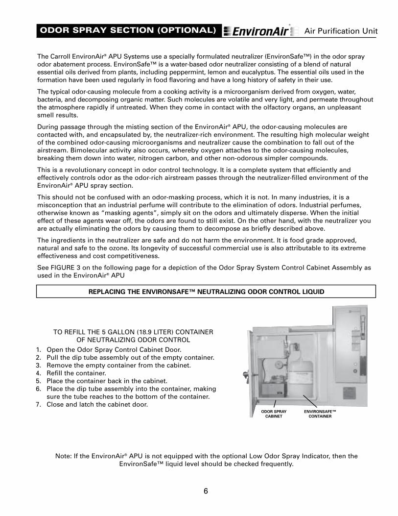
REPLACING THE ENVIRONSAFE™ NEUTRALIZING ODOR CONTROL LIQUID
Note: If the EnvironAir® APU is not equipped with the optional Low Odor Spray Indicator, then theEnvironSafe™ liquid level should be checked frequently.
ODOR SPRAY SECTION (OPTIONAL)
TO REFILL THE 5 GALLON (18.9 LITER) CONTAINER OF NEUTRALIZING ODOR CONTROL
1. Open the Odor Spray Control Cabinet Door.2. Pull the dip tube assembly out of the empty container.3. Remove the empty container from the cabinet.4. Refill the container.5. Place the container back in the cabinet.6. Place the dip tube assembly into the container, making
sure the tube reaches to the bottom of the container.7. Close and latch the cabinet door.
Air Purification Unit
ODOR SPRAY
CABINET
ENVIRONSAFE™
CONTAINER
7
ODOR SPRAY SECTION (OPTIONAL)
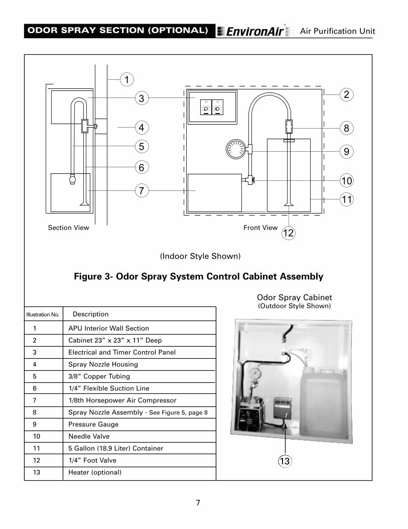
Figure 3- Odor Spray System Control Cabinet Assembly
1 APU Interior Wall Section
2 Cabinet 23” x 23” x 11” Deep
3 Electrical and Timer Control Panel
4 Spray Nozzle Housing
5 3/8” Copper Tubing
6 1/4” Flexible Suction Line
7 1/8th Horsepower Air Compressor
8 Spray Nozzle Assembly - See Figure 5, page 8
9 Pressure Gauge
10 Needle Valve
11 5 Gallon (18.9 Liter) Container
12 1/4” Foot Valve
13 Heater (optional)
Illustration No. Description
400
500
600
300
200
10015
SECONDS
CYCLETIMER
400
500
600
300
200
10015
SECONDS
SPRAYTIMER
2
8
9
10
11
12
7
6
5
4
3
1
Section View
(Indoor Style Shown)
Air Purification Unit
Front View
13
Odor Spray Cabinet(Outdoor Style Shown)

8
ODOR SPRAY SECTION (OPTIONAL)
To adjust the cycle and spray timers, open the OdorSpray Cabinet, and remove the screwed-in-place timercontrol cover plate.
CAUTION: Always de-energize the EnvironAir® APUbefore opening the Electrical and Timer Control Panelinside the Odor Spray Cabinet.
The Odor Spray Unit operates on spray-on andspray-off timed cycles while the APU unit is in the“Fan On” mode.
The Odor Spray Control includes two (2) timers,one (1) for the “Cycle Timer” (this is the spray“OFF” timer) and one (1) for the “Spray Timer”(this is the spray “ON” timer). Both timers arecalibrated and can be set between 5 and 600seconds. The factory/setting is always 15 seconds“ON” and 15 seconds “OFF.”
AIR PRESSUREFactory set to 20 PSIG
400
500
600
300
200
10015
SECONDS
CYCLETIMER
400
500
600
300
200
10015
SECONDS
SPRAYTIMER
FIGURE 5 - ODOR CONTROL SPRAY NOZZLE ASSEMBLY
109
8
5432
6
1
7
12
11
AIR INLET
ENVIRONSAFE™
ODOR ELIMINATOR
INLET
SPRAY
DISCHARGE
NOZZLE MAINTENANCE
To obtain the best performance from your nozzle, it may become necessary to clean it periodically.
The nozzle may become clogged and cease spraying due to factors such as dust, foreign particles accumulatedin the orifice (No.4 shown above), and/or leakage in the air or liquid section of the nozzle.
FIGURE - 4 ELECTRICAL CONTROLS
CYCLE TIMERTo set the “Off” period, turn the dial to the desired offtime interval.
SPRAY TIMERTo set the “On” period, turn the dial to the desired ontime interval.
Air Purification Unit
Illustration No. DESCRIPTION
1. WaIl mount and nut assembly2. Neoprene gasket3. Aircap4. Fluid Cap (orifice)5. Teflon gasket6. Barbed Fitting for Liquid Inlet7. Compression Fitting for Air Inlet8. Nozzle Body9. Teflon gasket10. Nozzle Cleanout Plug11. Air Inlet12. Liquid Inlet
Note: Nozzle is sold as an assembly, see item47 in the parts list.
Cycle andSpray Timers
9
The following procedure should be done to maintain the nozzle's performance:
1. Check the air line, which is connected from the compressor unit to the compression fitting and threadedinto the air inlet side of the nozzle, for any leakage.
2. Check the liquid suction line, which is connected to the liquid inlet side of the nozzle, and ensure that it isimmersed in the odor control solution.
3. If it appears that the nozzle is only blowing air and does not lift up the odor control solution out of thecontainer, do the following:
Remove the cleanout plug from the nozzle body and, using a very thin pin or wire, clean the hole in thefluid cap (orifice) and replace the cleanout plug. Remove the foot valve from the liquid container andinspect screen for clogging. Brush clean if clogged.
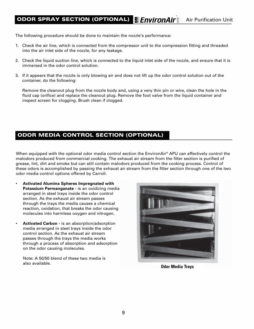
When equipped with the optional odor media control section the EnvironAir® APU can effectively control themalodors produced from commercial cooking. The exhaust air stream from the filter section is purified ofgrease, lint, dirt and smoke but can still contain malodors produced from the cooking process. Control ofthese odors is accomplished by passing the exhaust air stream from the filter section through one of the twoodor media control options offered by Carroll.
• Activated Alumina Spheres Impregnated with
Potassium Permanganate - is an oxidizing mediaarranged in steel trays inside the odor controlsection. As the exhaust air stream passesthrough the trays the media causes a chemicalreaction, oxidation, that breaks the odor causingmolecules into harmless oxygen and nitrogen.
• Activated Carbon - is an absorption/adsorptionmedia arranged in steel trays inside the odorcontrol section. As the exhaust air streampasses through the trays the media worksthrough a process of absorption and adsorptionon the odor causing molecules.
Note: A 50/50 blend of these two media is also available.
ODOR SPRAY SECTION (OPTIONAL)
ODOR MEDIA CONTROL SECTION (OPTIONAL)
Odor Media Trays
Air Purification Unit
10
ODOR MEDIA CONTROL SECTION (OPTIONAL)
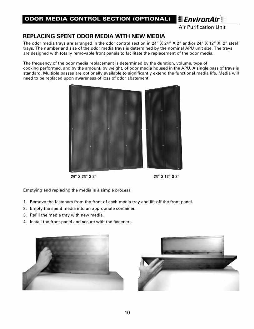
REPLACING SPENT ODOR MEDIA WITH NEW MEDIAThe odor media trays are arranged in the odor control section in 24” X 24” X 2” and/or 24” X 12” X 2” steeltrays. The number and size of the odor media trays is determined by the nominal APU unit size. The traysare designed with totally removable front panels to facilitate the replacement of the odor media.
The frequency of the odor media replacement is determined by the duration, volume, type of cooking performed, and by the amount, by weight, of odor media housed in the APU. A single pass of trays isstandard. Multiple passes are optionally available to significantly extend the functional media life. Media willneed to be replaced upon awareness of loss of odor abatement.
Emptying and replacing the media is a simple process.
1. Remove the fasteners from the front of each media tray and lift off the front panel.
2. Empty the spent media into an appropriate container.
3. Refill the media tray with new media.
4. Install the front panel and secure with the fasteners.
24” X 24” X 2” 24” X 12” X 2”
Air Purification Unit
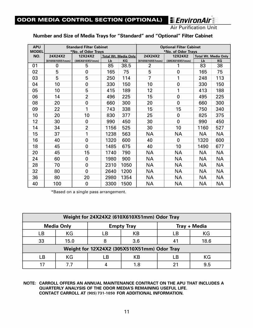
Weight for 24X24X2 (610X610X51mm) Odor Tray
Media Only Empty Tray Tray + Media
LB KG LB KB LB KG
33 15.0 8 3.6 41 18.6
Weight for 12X24X2 (305X510X51mm) Odor Tray
LB KG LB KB LB KG
17 7.7 4 1.8 21 9.5
11
ODOR MEDIA CONTROL SECTION (OPTIONAL)
NOTE: CARROLL OFFERS AN ANNUAL MAINTENANCE CONTRACT ON THE APU THAT INCLUDES A
QUARTERLY ANALYSIS OF THE ODOR MEDIA’S REMAINING USEFUL LIFE.
CONTACT CARROLL AT (800) 444-9696 FOR ADDITIONAL INFORMATION.
01 0 5 85 38.5 2 1 83 3802 5 0 165 75 5 0 165 7503 5 5 250 114 7 1 248 11304 10 0 330 150 10 0 330 15005 10 5 415 189 12 1 413 18806 14 2 496 225 15 0 495 22508 20 0 660 300 20 0 660 30009 22 1 743 338 15 15 750 34010 20 10 830 377 25 0 825 37512 30 0 990 450 30 0 990 45014 34 2 1156 525 30 10 1160 52715 37 1 1238 563 NA NA NA NA16 40 0 1320 600 40 0 1320 60018 45 0 1485 675 40 10 1490 67720 45 15 1740 790 NA NA NA NA24 60 0 1980 900 NA NA NA NA28 70 0 2310 1050 NA NA NA NA32 80 0 2640 1200 NA NA NA NA36 80 20 2980 1354 NA NA NA NA40 100 0 3300 1500 NA NA NA NA
APU Standard Filter Cabinet Optional Filter Cabinet
MODEL *No. of Odor Trays *No. of Odor Trays
NO. 24X24X2 12X24X2 Total Wt. Media Only 24X24X2 12X24X2 Total Wt. Media Only
(610X610X51mm) (305X610X51mm) Lb KG (610X610X51mm) (305X610X51mm) Lb KG
Number and Size of Media Trays for “Standard” and “Optional” Filter Cabinet
*Based on a single pass arrangement.
Air Purification Unit
(905) 731-1050
12
MATERIAL SAFETY DATA SHEET
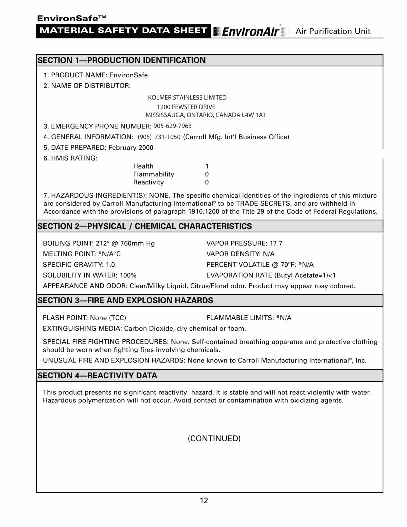
1. PRODUCT NAME: EnvironSafe
2. NAME OF DISTRIBUTOR:
CARROLL MANUFACTURING INTERNATIONAL®, INC.23 VREELAND ROAD
FLORHAM PARK, NEW JERSEY 07932-1990
3. EMERGENCY PHONE NUMBER: (800) 764-7661 (New Jersey Poison Control)
4. GENERAL INFORMATION: (973) 966-6000 (Carroll Mfg. Int’l Business Office)
5. DATE PREPARED: February 2000
6. HMIS RATING:Health 1Flammability 0Reactivity 0
7. HAZARDOUS INGREDIENT(S): NONE. The specific chemical identities of the ingredients of this mixtureare considered by Carroll Manufacturing International® to be TRADE SECRETS, and are withheld inAccordance with the provisions of paragraph 1910.1200 of the Title 29 of the Code of Federal Regulations.
BOILING POINT: 212° @ 760mm Hg VAPOR PRESSURE: 17.7
MELTING POINT: *N/A°C VAPOR DENSITY: N/A
SPECIFIC GRAVITY: 1.0 PERCENT VOLATILE @ 70°F: *N/A
SOLUBILITY IN WATER: 100% EVAPORATION RATE (Butyl Acetate=1)<1
APPEARANCE AND ODOR: Clear/Milky Liquid, Citrus/Floral odor. Product may appear rosy colored.
FLASH POINT: None (TCC) FLAMMABLE LIMITS: *N/A
EXTINGUISHING MEDIA: Carbon Dioxide, dry chemical or foam.
SPECIAL FIRE FIGHTING PROCEDURES: None. Self-contained breathing apparatus and protective clothing should be worn when fighting fires involving chemicals.
UNUSUAL FIRE AND EXPLOSION HAZARDS: None known to Carroll Manufacturing International®, Inc.
This product presents no significant reactivity hazard. It is stable and will not react violently with water.Hazardous polymerization will not occur. Avoid contact or contamination with oxidizing agents.
SECTION 1—PRODUCTION IDENTIFICATION
SECTION 2—PHYSICAL / CHEMICAL CHARACTERISTICS
SECTION 3—FIRE AND EXPLOSION HAZARDS
SECTION 4—REACTIVITY DATA
(CONTINUED)
EnvironSafeTM
Air Purification Unit
1200 FEWSTER DRIVE MISSISSAUGA, ONTARIO, CANADA L4W 1A1
(905) 731-1050
KOLMER STAINLESS LIMITED
905-629-7963
13
MATERIAL SAFETY DATA SHEET
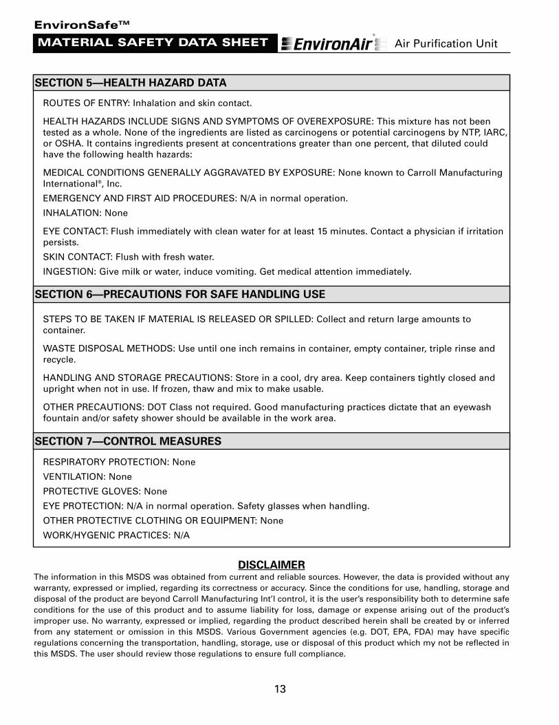
ROUTES OF ENTRY: Inhalation and skin contact.
HEALTH HAZARDS INCLUDE SIGNS AND SYMPTOMS OF OVEREXPOSURE: This mixture has not beentested as a whole. None of the ingredients are listed as carcinogens or potential carcinogens by NTP, IARC,or OSHA. It contains ingredients present at concentrations greater than one percent, that diluted couldhave the following health hazards:
MEDICAL CONDITIONS GENERALLY AGGRAVATED BY EXPOSURE: None known to Carroll ManufacturingInternational®, Inc.
EMERGENCY AND FIRST AID PROCEDURES: N/A in normal operation.
INHALATION: None
EYE CONTACT: Flush immediately with clean water for at least 15 minutes. Contact a physician if irritationpersists.
SKIN CONTACT: Flush with fresh water.
INGESTION: Give milk or water, induce vomiting. Get medical attention immediately.
STEPS TO BE TAKEN IF MATERIAL IS RELEASED OR SPILLED: Collect and return large amounts tocontainer.
WASTE DISPOSAL METHODS: Use until one inch remains in container, empty container, triple rinse andrecycle.
HANDLING AND STORAGE PRECAUTIONS: Store in a cool, dry area. Keep containers tightly closed andupright when not in use. If frozen, thaw and mix to make usable.
OTHER PRECAUTIONS: DOT Class not required. Good manufacturing practices dictate that an eyewashfountain and/or safety shower should be available in the work area.
RESPIRATORY PROTECTION: None
VENTILATION: None
PROTECTIVE GLOVES: None
EYE PROTECTION: N/A in normal operation. Safety glasses when handling.
OTHER PROTECTIVE CLOTHING OR EQUIPMENT: None
WORK/HYGENIC PRACTICES: N/A
SECTION 5—HEALTH HAZARD DATA
SECTION 6—PRECAUTIONS FOR SAFE HANDLING USE
SECTION 7—CONTROL MEASURES
DISCLAIMERThe information in this MSDS was obtained from current and reliable sources. However, the data is provided without anywarranty, expressed or implied, regarding its correctness or accuracy. Since the conditions for use, handling, storage anddisposal of the product are beyond Carroll Manufacturing Int’l control, it is the user’s responsibility both to determine safeconditions for the use of this product and to assume liability for loss, damage or expense arising out of the product’simproper use. No warranty, expressed or implied, regarding the product described herein shall be created by or inferredfrom any statement or omission in this MSDS. Various Government agencies (e.g. DOT, EPA, FDA) may have specificregulations concerning the transportation, handling, storage, use or disposal of this product which my not be reflected inthis MSDS. The user should review those regulations to ensure full compliance.
EnvironSafeTM
Air Purification Unit

14
MATERIAL SAFETY DATA SHEET
1. PRODUCT NAME: CMI Activated Carbon
2. NAME OF DISTRIBUTOR:
CARROLL MANUFACTURING INTERNATIONAL®, INC.23 VREELAND ROAD
FLORHAM PARK, NEW JERSEY 07932-1990
3. EMERGENCY PHONE NUMBER: (800) 764-7661 (New Jersey Poison Control)
4. GENERAL INFORMATION: (973) 966-6000 (Carroll Mfg. Int’l Business Office)
5. DATE PREPARED: February 2000
6. CHEMICAL NAME AND SYNONYMS: Bituminous coal based activated carbon
7. CAS NO. 7440-44-0
This product is non-hazardous according to OSHA Hazard Communication Law (29 CFR part 1910)
Components %wt. OSHA ACGIH other(PEL) (TLV)
Activated Carbon 100% N/A N/A N/A
BOILING POINT: N/A SPECIFIC GRAVITY: 1.8-2.1VAPOR PRESSURE: N/A PERCENT VOLATILE: N/AVAPOR DENSITY: N/A EVAPORATION RATE: N/ASOLUBILITY IN WATER: insolubleAPPEARANCE AND ODOR: Black granular solid, odorless.
FLASH POINT: None AUTO-IGNITION TEMP: 340° CEXTINGUISHING MEDIA: Water (not rated by NFPA) LOW EXPLOSIVE LIMIT: N/ASPECIAL FIRE FIGHTING PROCEDURES: None. UPPER EXPLOSIVE LIMIT: N/AFLAMMABLE LIMITS: N/AUNUSUAL FIRE AND EXPLOSION HAZARDS: Contact with strong oxidizers such as ozone, liquid oxygen,chlorine, permanganates, peroxides, etc. may result in fire.STORAGE: in sealed containers
STABILITY: StableCONDITIONS TO AVOID: close proximity to solvents, open flames, strong oxidizing and reducing agents.
INCOMPATIBILITY (MATERIAL TO AVOID): Contact with strong oxidizers such as ozone, liquid oxygen,chlorine, permanganates, peroxides, etc. may result in fire.HAZARDOUS DECOMPOSITION PRODUCTS: carbon monoxide may be generated in the event of a fire.POLYMERIZATION: N/A
SECTION 1—PRODUCTION IDENTIFICATION
SECTION 3—PHYSICAL / CHEMICAL CHARACTERISTICS
SECTION 4—FIRE AND EXPLOSION HAZARDS
SECTION 5—REACTIVITY DATA
(CONTINUED)
Activated Carbon
Air Purification Unit
SECTION 2—HAZARDOUS INGREDIENT(S)
1200 FEWSTER DRIVE MISSISSAUGA, ONTARIO, CANADA L4W 1A1
(905) 731-1050
KOLMER STAINLESS LIMITED
905-629-7963
15
MATERIAL SAFETY DATA SHEET
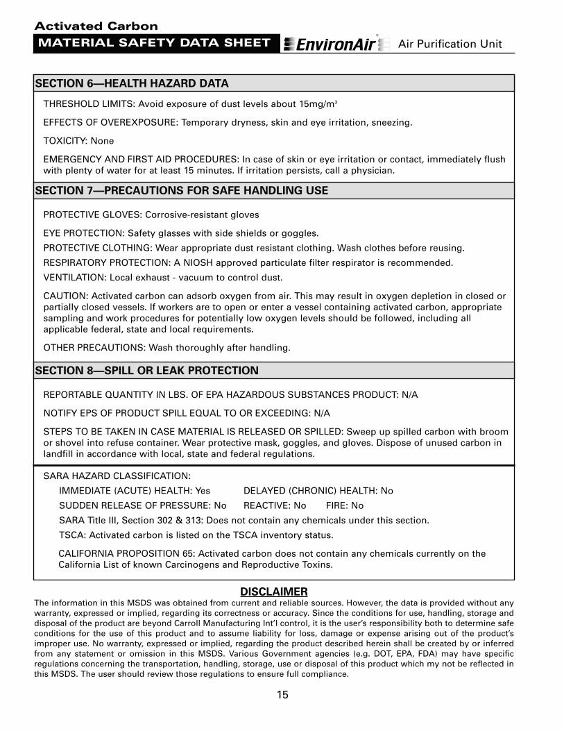
THRESHOLD LIMITS: Avoid exposure of dust levels about 15mg/m3
EFFECTS OF OVEREXPOSURE: Temporary dryness, skin and eye irritation, sneezing.
TOXICITY: None
EMERGENCY AND FIRST AID PROCEDURES: In case of skin or eye irritation or contact, immediately flushwith plenty of water for at least 15 minutes. If irritation persists, call a physician.
PROTECTIVE GLOVES: Corrosive-resistant gloves
EYE PROTECTION: Safety glasses with side shields or goggles.
PROTECTIVE CLOTHING: Wear appropriate dust resistant clothing. Wash clothes before reusing.
RESPIRATORY PROTECTION: A NIOSH approved particulate filter respirator is recommended.
VENTILATION: Local exhaust - vacuum to control dust.
CAUTION: Activated carbon can adsorb oxygen from air. This may result in oxygen depletion in closed orpartially closed vessels. If workers are to open or enter a vessel containing activated carbon, appropriatesampling and work procedures for potentially low oxygen levels should be followed, including allapplicable federal, state and local requirements.
OTHER PRECAUTIONS: Wash thoroughly after handling.
REPORTABLE QUANTITY IN LBS. OF EPA HAZARDOUS SUBSTANCES PRODUCT: N/A
NOTIFY EPS OF PRODUCT SPILL EQUAL TO OR EXCEEDING: N/A
STEPS TO BE TAKEN IN CASE MATERIAL IS RELEASED OR SPILLED: Sweep up spilled carbon with broomor shovel into refuse container. Wear protective mask, goggles, and gloves. Dispose of unused carbon inlandfill in accordance with local, state and federal regulations.
SARA HAZARD CLASSIFICATION:
IMMEDIATE (ACUTE) HEALTH: Yes DELAYED (CHRONIC) HEALTH: No
SUDDEN RELEASE OF PRESSURE: No REACTIVE: No FIRE: No
SARA Title III, Section 302 & 313: Does not contain any chemicals under this section.
TSCA: Activated carbon is listed on the TSCA inventory status.
CALIFORNIA PROPOSITION 65: Activated carbon does not contain any chemicals currently on theCalifornia List of known Carcinogens and Reproductive Toxins.
SECTION 6—HEALTH HAZARD DATA
SECTION 7—PRECAUTIONS FOR SAFE HANDLING USE
SECTION 8—SPILL OR LEAK PROTECTION
DISCLAIMERThe information in this MSDS was obtained from current and reliable sources. However, the data is provided without anywarranty, expressed or implied, regarding its correctness or accuracy. Since the conditions for use, handling, storage anddisposal of the product are beyond Carroll Manufacturing Int’l control, it is the user’s responsibility both to determine safeconditions for the use of this product and to assume liability for loss, damage or expense arising out of the product’simproper use. No warranty, expressed or implied, regarding the product described herein shall be created by or inferredfrom any statement or omission in this MSDS. Various Government agencies (e.g. DOT, EPA, FDA) may have specificregulations concerning the transportation, handling, storage, use or disposal of this product which my not be reflected inthis MSDS. The user should review those regulations to ensure full compliance.
Activated Carbon
Air Purification Unit
16
MATERIAL SAFETY DATA SHEET
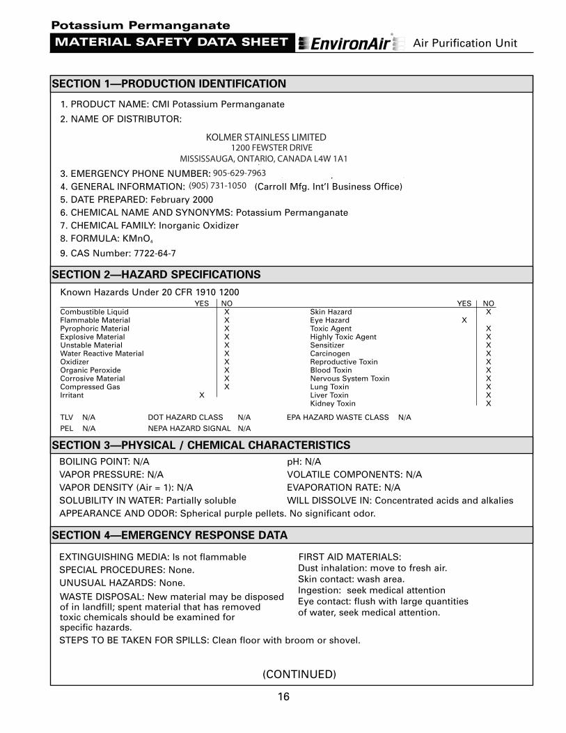
1. PRODUCT NAME: CMI Potassium Permanganate
2. NAME OF DISTRIBUTOR:
CARROLL MANUFACTURING INTERNATIONAL®, INC.23 VREELAND ROAD
FLORHAM PARK, NEW JERSEY 07932-19903. EMERGENCY PHONE NUMBER: (800) 764-7661 (New Jersey Poison Control)4. GENERAL INFORMATION: (973) 966-6000 (Carroll Mfg. Int’l Business Office)5. DATE PREPARED: February 20006. CHEMICAL NAME AND SYNONYMS: Potassium Permanganate 7. CHEMICAL FAMILY: Inorganic Oxidizer 8. FORMULA: KMnO4
9. CAS Number: 7722-64-7
Known Hazards Under 20 CFR 1910 1200
BOILING POINT: N/A pH: N/AVAPOR PRESSURE: N/A VOLATILE COMPONENTS: N/AVAPOR DENSITY (Air = 1): N/A EVAPORATION RATE: N/ASOLUBILITY IN WATER: Partially soluble WILL DISSOLVE IN: Concentrated acids and alkaliesAPPEARANCE AND ODOR: Spherical purple pellets. No significant odor.
EXTINGUISHING MEDIA: Is not flammable FIRST AID MATERIALS:SPECIAL PROCEDURES: None. UNUSUAL HAZARDS: None.
WASTE DISPOSAL: New material may be disposed of in landfill; spent material that has removedtoxic chemicals should be examined for specific hazards.STEPS TO BE TAKEN FOR SPILLS: Clean floor with broom or shovel.
SECTION 1—PRODUCTION IDENTIFICATION
SECTION 3—PHYSICAL / CHEMICAL CHARACTERISTICS
SECTION 4—EMERGENCY RESPONSE DATA
(CONTINUED)
Potassium Permanganate
Dust inhalation: move to fresh air.Skin contact: wash area.Ingestion: seek medical attentionEye contact: flush with large quantitiesof water, seek medical attention.
SECTION 2—HAZARD SPECIFICATIONS
YES NO YES NOCombustible Liquid X Skin Hazard XFlammable Material X Eye Hazard XPyrophoric Material X Toxic Agent XExplosive Material X Highly Toxic Agent XUnstable Material X Sensitizer XWater Reactive Material X Carcinogen XOxidizer X Reproductive Toxin XOrganic Peroxide X Blood Toxin XCorrosive Material X Nervous System Toxin XCompressed Gas X Lung Toxin XIrritant X Liver Toxin X
Kidney Toxin X
TLV N/A DOT HAZARD CLASS N/A EPA HAZARD WASTE CLASS N/A
PEL N/A NEPA HAZARD SIGNAL N/A
Air Purification Unit
1200 FEWSTER DRIVE MISSISSAUGA, ONTARIO, CANADA L4W 1A1
(905) 731-1050905-629-7963
KOLMER STAINLESS LIMITED
17
MATERIAL SAFETY DATA SHEET
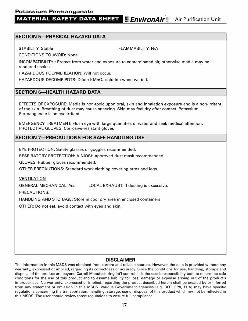
STABILITY: Stable FLAMMABILITY: N/A
CONDITIONS TO AVOID: None.
INCOMPATIBILITY : Protect from water and exposure to contaminated air, otherwise media may berendered useless.
HAZARDOUS POLYMERIZATION: Will not occur.
HAZARDOUS DECOMP PDTS: Dilute KMnO4 solution when wetted.
EFFECTS OF EXPOSURE: Media is non-toxic upon oral, skin and inhalation exposure and is a non-irritantof the skin. Breathing of dust may cause sneezing. Skin may feel dry after contact. PotassiumPermanganate is an eye irritant.
EMERGENCY TREATMENT: Flush eye with large quantities of water and seek medical attention.PROTECTIVE GLOVES: Corrosive-resistant gloves
EYE PROTECTION: Safety glasses or goggles recommended.
RESPIRATORY PROTECTION: A NIOSH approved dust mask recommended.
GLOVES: Rubber gloves recommended.
OTHER PRECAUTIONS: Standard work clothing covering arms and legs.
VENTILATION
GENERAL MECHANICAL: Yes LOCAL EXHAUST: If dusting is excessive.
PRECAUTIONS:
HANDLING AND STORAGE: Store in cool dry area in enclosed containers
OTHER: Do not eat, avoid contact with eyes and skin.
SECTION 6—HEALTH HAZARD DATA
SECTION 7—PRECAUTIONS FOR SAFE HANDLING USE
DISCLAIMERThe information in this MSDS was obtained from current and reliable sources. However, the data is provided without anywarranty, expressed or implied, regarding its correctness or accuracy. Since the conditions for use, handling, storage anddisposal of the product are beyond Carroll Manufacturing Int’l control, it is the user’s responsibility both to determine safeconditions for the use of this product and to assume liability for loss, damage or expense arising out of the product’simproper use. No warranty, expressed or implied, regarding the product described herein shall be created by or inferredfrom any statement or omission in this MSDS. Various Government agencies (e.g. DOT, EPA, FDA) may have specificregulations concerning the transportation, handling, storage, use or disposal of this product which my not be reflected inthis MSDS. The user should review those regulations to ensure full compliance.
Potassium Permanganate
SECTION 5—PHYSICAL HAZARD DATA
Air Purification Unit
18
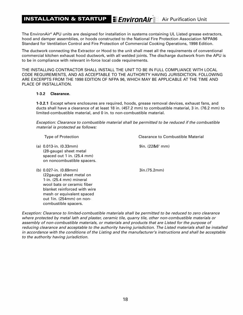
The EnvironAir® APU units are designed for installation in systems containing UL Listed grease extractors,hood and damper assemblies, or hoods constructed to the National Fire Protection Association NFPA96Standard for Ventilation Control and Fire Protection of Commercial Cooking Operations, 1998 Edition.
The ductwork connecting the Extractor or Hood to the unit shall meet all the requirements of conventionalcommercial kitchen exhaust hood ductwork, with all welded joints. The discharge ductwork from the APU isto be in compliance with relevant in-force local code requirements.
THE INSTALLING CONTRACTOR SHALL INSTALL THE UNIT TO BE IN FULL COMPLIANCE WITH LOCALCODE REQUIREMENTS, AND AS ACCEPTABLE TO THE AUTHORITY HAVING JURISDICTION. FOLLOWINGARE EXCERPTS FROM THE 1998 EDITION OF NFPA 96, WHICH MAY BE APPLICABLE AT THE TIME ANDPLACE OF INSTALLATION.
1-3.2 Clearance.
1-3.2.1 Except where enclosures are required, hoods, grease removal devices, exhaust fans, andducts shall have a clearance of at least 18 in. (457.2 mm) to combustible material, 3 in. (76.2 mm) tolimited-combustible material, and 0 in. to non-combustible material.
Exception: Clearance to combustible material shall be permitted to be reduced if the combustiblematerial is protected as follows:
Type of Protection Clearance to Combustible Material
(a) 0.013-in. (0.33mm) 9in. (22&6' mm)(28-gauge) sheet metalspaced out 1 in. (25.4 mm)on noncombustible spacers.
(b) 0.027-in. (0.69mm) 3in.(75.2mm)(22gauge) sheet metal on1-in. (25.4 mm) mineralwool bats or ceramic fiberblanket reinforced with wiremesh or equivalent spacedout 1in. (254mm) on non-combustible spacers.
Exception: Clearance to limited-combustible materials shall be permitted to be reduced to zero clearancewhere protected by metal lath and plaster, ceramic tile, quarry tile, other non-combustible materials orassembly of non-combustible materials, or materials and products that are Listed for the purpose ofreducing clearance and acceptable to the authority having jurisdiction. The Listed materials shall be installedin accordance with the conditions of the Listing and the manufacturer's instructions and shall be acceptableto the authority having jurisdiction.
INSTALLATION & STARTUP Air Purification Unit
19
6-3.1 Other Equipment Fume incinerators, thermal recovery units, air pollution control devices, or otherdevices shall be permitted to be installed in ducts or hoods or located in the path of travel of exhaustproducts where specifically approved for such use. Downgrading other parts of the exhaust system due tothe installation of these approved devices, whether listed or not, shall not be allowed.
6-3.2 Any equipment listed or otherwise, that provides secondary filtration or air pollution control,installed in the path of travel of exhaust products shall be provided with an approved automatic fireextinguishing system for the protection of the component sections of the equipment and shall includeprotection of the ductwork downstream of the equipment, whether or not the equipment is providedwith a damper. If the equipment can be a source of ignition, it shall be provided with appropriatedetection to operate the fire extinguishing system.
Note: A set of project specific drawings and a copy of this technical manual accompanyeach EnvironAir® APU when shipped. These documents are to be referred to forinstallation, technical data, and maintenance.
Standard Wiring Diagrams for the EnvironAir® APU are located on pages 32-35 of this manual.
THE START-UP SHEETS ON THE FOLLOWING TWO PAGES ARE TO BE FOLLOWED AND APPROPRIATEINFORMATION FILLED IN AND LEFT IN THE MANUAL. A DUPLICATE SET IS FOUND AT THE END OF THISMANUAL. IT IS TO BE FILLED IN AND RETURNED TO CARROLL MANUFACTURING INTERNATIONAL®.
THE FOLLOWING APPLIES IF THE APU IS EQUIPPED WITH THE OPTIONAL FAN/BLOWERSECTION BY CARROLL:
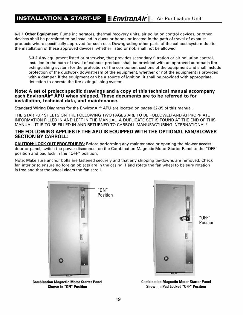
CAUTION: LOCK OUT PROCEDURES: Before performing any maintenance or opening the blower access door or panel, switch the power disconnect on the Combination Magnetic Motor Starter Panel to the “OFF”position and pad lock in the “OFF” position.
INSTALLATION & START-UP
Combination Magnetic Motor Starter PanelShown in “ON” Position
Combination Magnetic Motor Starter PanelShown in Pad Locked “OFF” Position
Air Purification Unit
“ON” Position
“OFF” Position
Note: Make sure anchor bolts are fastened securely and that any shipping tie-downs are removed. Checkfan interior to ensure no foreign objects are in the casing. Hand rotate the fan wheel to be sure rotationis free and that the wheel clears the fan scroll.
20
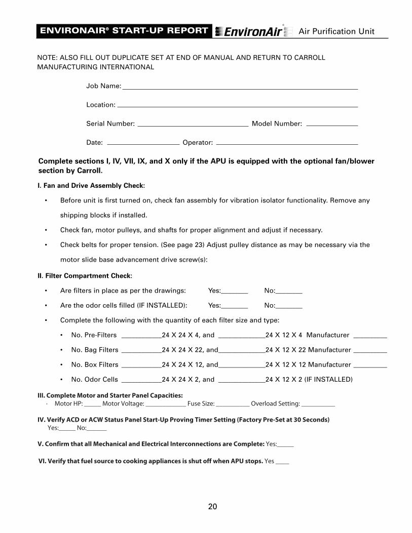
ENVIRONAIR® START-UP REPORT
NOTE: ALSO FILL OUT DUPLICATE SET AT END OF MANUAL AND RETURN TO CARROLLMANUFACTURING INTERNATIONAL
Job Name:
Location:
Serial Number: Model Number:
Date: Operator:
Complete sections I, IV, VII, IX, and X only if the APU is equipped with the optional fan/blower
section by Carroll.
I. Fan and Drive Assembly Check:
• Before unit is first turned on, check fan assembly for vibration isolator functionality. Remove any
shipping blocks if installed.
• Check fan, motor pulleys, and shafts for proper alignment and adjust if necessary.
• Check belts for proper tension. (See page 23) Adjust pulley distance as may be necessary via the
motor slide base advancement drive screw(s):
II. Filter Compartment Check:
• Are filters in place as per the drawings: Yes:________ No:________
• Are the odor cells filled (IF INSTALLED): Yes:________ No:________
• Complete the following with the quantity of each filter size and type:
• No. Pre-Filters ____________24 X 24 X 4, and ______________24 X 12 X 4 Manufacturer __________
• No. Bag Filters ____________24 X 24 X 22, and______________24 X 12 X 22 Manufacturer __________
• No. Box Filters ____________24 X 24 X 12, and______________24 X 12 X 12 Manufacturer __________
• No. Odor Cells ____________24 X 24 X 2, and ______________24 X 12 X 2 (IF INSTALLED)
III. Verify Firestat Setting of 200°F (93°C) OK_________
IV. Complete Motor and Starter Panel Capacities:
• Motor HP: __________ Motor Voltage: ____________ Fuse Size: __________ Overload Setting: __________
V. Verify ACD or ACW Status Panel Start-Up Proving Timer Setting (Factory Pre-Set at 30 Seconds)
Yes:_____ No:______
VI. Confirm that all Mechanical and Electrical Interconnections are Complete: Yes:_____
Air Purification Unit
III. Complete Motor and Starter Panel Capacities:
· Motor HP: _____ Motor Voltage: ____________ Fuse Size: __________ Overload Setting: __________
IV. Verify ACD or ACW Status Panel Start-Up Proving Timer Setting (Factory Pre-Set at 30 Seconds)
Yes:_____ No:______
V. Confirm that all Mechanical and Electrical Interconnections are Complete: Yes:_____
VI. Verify that fuel source to cooking appliances is shut off when APU stops. Yes ____
21
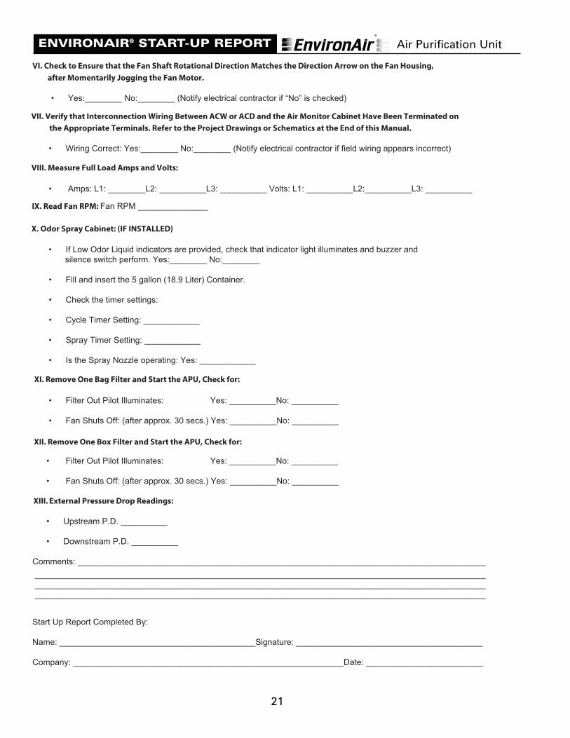
ENVIRONAIR® START-UP REPORT
VII. Check to Ensure that the Fan Shaft Rotational Direction Matches the Direction Arrow on the Fan Housing,
after Momentarily Jogging the Fan Motor.
• Yes:________ No:________ (Notify electrical contractor if “No” is checked)
VIII. Verify that Interconnection Wiring Between ACW or ACD and the Air Monitor Cabinet Have Been
Terminated on the Appropriate Terminals. Refer to the Project Drawings or Schematics at the End of
this Manual.
• Wiring Correct: Yes:________ No:________ (Notify electrical contractor if field wiring appears incorrect)
IX. Measure Full Load Amps and Volts:
• Amps: L1: ________L2: __________L3: __________ Volts: L1: __________L2:__________L3: __________
X. Read Fan RPM: Fan RPM _______________
XI. Odor Spray Cabinet: (IF INSTALLED)
• If Low Odor Spray indicators are provided, check that indicator light illuminates and buzzer and
silence switch perform. Yes:________ No:________
• Fill and insert the 5 gallon (18.9 Liter) Container.
• Check the timer settings:
• Cycle Timer Setting: ____________
• Spray Timer Setting: ____________
• Is the Spray Nozzle operating: Yes: ____________
XII. Remove One Bag Filter and Start the APU, Check for:
• Filter Out Pilot Illuminates: Yes: __________No: __________
• Fan Shuts Off: (after approx. 30 secs.) Yes: __________No: __________
XIII. Remove One Box Filter and Start the APU, Check for:
• Filter Out Pilot Illuminates: Yes: __________No: __________
• Fan Shuts Off: (after approx. 30 secs.) Yes: __________No: __________
Comments: ________________________________________________________________________________________
__________________________________________________________________________________________
__________________________________________________________________________________________
__________________________________________________________________________________________
__________________________________________________________________________________________
Start Up Report Completed By:
Name: __________________________________________Signature: ________________________________________
Company: __________________________________________________________Date: __________________________
Air Purification Unit
(Observed momentarily via Box FilterAccess Door with one Filter removed)
VII. Check to Ensure that the Fan Shaft Rotational Direction Matches the Direction Arrow on the Fan Housing,
after Momentarily Jogging the Fan Motor.
• Yes:________ No:________ (Notify electrical contractor if “No” is checked)
VIII. Verify that Interconnection Wiring Between ACW or ACD and the Air Monitor Cabinet Have Been Terminated on
the Appropriate Terminals. Refer to the Project Drawings or Schematics at the End of this Manual.
• Wiring Correct: Yes:________ No:________ (Notify electrical contractor if field wiring appears incorrect)
IX. Measure Full Load Amps and Volts:
• Amps: L1: ________L2: __________L3: __________ Volts: L1: __________L2:__________L3: __________
X. Read Fan RPM: Fan RPM _______________
XI. Odor Spray Cabinet: (IF INSTALLED)
• If Low Odor Liquid indicators are provided, check that indicator light illuminates and buzzer andsilence switch perform. Yes:________ No:________
• Fill and insert the 5 gallon (18.9 Liter) Container.
• Check the timer settings:
• Cycle Timer Setting: ____________
• Spray Timer Setting: ____________
• Is the Spray Nozzle operating: Yes: ____________
XII. Remove One Bag Filter and Start the APU, Check for:
• Filter Out Pilot Illuminates: Yes: __________No: __________
• Fan Shuts Off: (after approx. 30 secs.) Yes: __________No: __________
XIII. Remove One Box Filter and Start the APU, Check for:
• Filter Out Pilot Illuminates: Yes: __________No: __________
• Fan Shuts Off: (after approx. 30 secs.) Yes: __________No: __________
XIV. External Pressure Drop Readings:
• Upstream P.D. __________
• Downstream P.D. __________
Comments: _______________________________________________________________________________________________________________________________________________________________________
______________________________________________________________________________________________________________________________________________________________________________________________________________________________________________________________________________________________________
Start Up Report Completed By:
Name: __________________________________________Signature: ________________________________________
Company: __________________________________________________________Date: __________________________
__________________________________________________________________________________________________ __________________________________________________________________________________________________ __________________________________________________________________________________________________
VII. Verify that Interconnection Wiring Between ACW or ACD and the Air Monitor Cabinet Have Been Terminated on
VIII. Measure Full Load Amps and Volts:
IX. Read Fan RPM: Fan RPM _______________
X. Odor Spray Cabinet: (IF INSTALLED)
XI. Remove One Bag Filter and Start the APU, Check for:
XII. Remove One Box Filter and Start the APU, Check for:
XIII.
VI. Check to Ensure that the Fan Shaft Rotational Direction Matches the Direction Arrow on the Fan Housing,

APU SUGGESTED FILTER SECTION MAINTENANCE SCHEDULE:AT LEAST EVERY MONTH (Heavy usage may require more frequent maintenance)1. Check the APU 4-inch pre-filters; replace as necessary.2. Check 95% ASHRAE 52.1-92 bag filters; replace as necessary.
EVERY THREE MONTHS1. Check APU filters as above.2. Check the 99% ASHRAE 52.1-92, 95% DOP Box Filters; replace as necessary
EVERY SIX MONTHS1. Complete three-month inspection, as above.2. Check integrity of any installed fusible links. On alternate six months, replace all fusible links.
Note: Either directly, or via a service agreement, unit expendables should be immediatelyavailable for replacement. These include a set of drive belts, full filter sets, and odorabatement media or EnvironSafe™ Liquid Neutralizer.
MAINTENANCE INSTRUCTIONS FOR FAN/BLOWER SECTIONNote: The maintenance instructions on pages 22-24 apply specifically to the APU if equipped with theoptional fan/blower section by Carroll. This information may also be appropriate for a fan/blower sectionprovided by others.
Periodically inspect fan scroll and wheel blades for dirt build up, and remove any such build up. If a build upis allowed to accumulate and a portion becomes dislodged, the wheel may go out of balance and causeexcessive bearing wear and premature failure.
When ordering replacement fan assembly parts, provide fan model and serial numbers found on theattached nameplate, along with a complete description of the part required.
V-BELT DRIVES:
Periodically check the belt tension and adjust if necessary. Loose belts will slip over the sheaves and causerapid belt wear and burnout. Excessive tension will overload bearings and cause premature bearing failure.As a rough rule of thumb, applying a fair degree of thumb force to a run of the belt mid-way betweensheaves will result in deflecting the belt about 1/64” per inch of the distance between sheave centers underproper tension. Check the alignment of fan and motor sheaves to ensure they are in line, check motor andfan shafts to make sure they are parallel.
When replacement belts are required, replace with a complete new matched set. Retain old belts foremergency use only. When changing belts, loosen tension. Do not force belts over the sheaves. Spare beltsshould be stored in cool, dark, dry storage.
BELTS AND DRIVES BASICS• Belts are, in general, rated to yield a minimum of 3,000 hours of useful life if all instructions are properly
followed.
• DRIVE ALIGNMENT- Drive alignment is one of the most common sources of drive performance problems.Misaligned drives can exhibit symptoms such as high belt tracking forces, uneven belt wear, high noiselevels, and tensile cord failure. The two primary types of drive misalignment are angular and parallel.
Angular misalignment results when the motor and fan shafts are not parallel. As a result, the belt tensilecords are not loaded evenly, resulting in uneven pressure and accelerated belt wear.
Parallel misalignment results from pulleys being mounted out of line from each other. Parallelmisalignment is of concern with V-type belts because they run in pulley grooves and are unable to free-float on the pulleys. Parallel misalignment can cause the belts to become trapped between the oppositepulley flanges, causing serious performance problems.
22
MAINTENANCE INSTRUCTIONS Air Purification Unit
23
MAINTENANCE INSTRUCTIONS Air Purification Unit
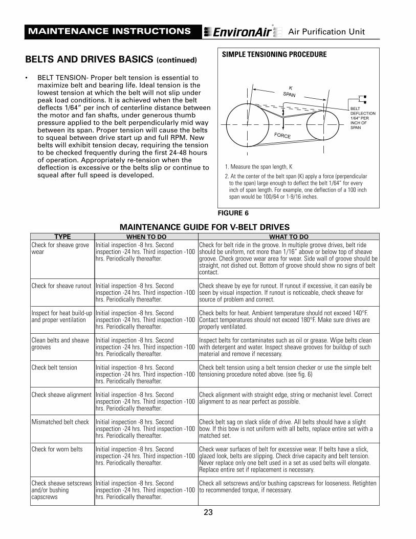
BELTS AND DRIVES BASICS (continued)
• BELT TENSION- Proper belt tension is essential tomaximize belt and bearing life. Ideal tension is thelowest tension at which the belt will not slip underpeak load conditions. It is achieved when the beltdeflects 1/64” per inch of centerline distance betweenthe motor and fan shafts, under generous thumbpressure applied to the belt perpendicularly mid waybetween its span. Proper tension will cause the beltsto squeal between drive start up and full RPM. Newbelts will exhibit tension decay, requiring the tensionto be checked frequently during the first 24-48 hoursof operation. Appropriately re-tension when thedeflection is excessive or the belts slip or continue tosqueal after full speed is developed.
SPANK
FORCE
BELTDEFLECTION1/64" PERINCH OF SPAN
1. Measure the span length, K
2. At the center of the belt span (K) apply a force (perpendicularto the span) large enough to deflect the belt 1/64” for everyinch of span length. For example, one deflection of a 100 inchspan would be 100/64 or 1-9/16 inches.
SIMPLE TENSIONING PROCEDURE
FIGURE 6
TYPE
Check for sheave grovewear
Check for sheave runout
Inspect for heat build-upand proper ventilation
Clean belts and sheavegrooves
Check belt tension
Check sheave alignment
Mismatched belt check
Check for worn belts
Check sheave setscrewsand/or bushingcapscrews
WHEN TO DO
Initial inspection -8 hrs. Secondinspection -24 hrs. Third inspection -100hrs. Periodically thereafter.
Initial inspection -8 hrs. Secondinspection -24 hrs. Third inspection -100hrs. Periodically thereafter.
Initial inspection -8 hrs. Secondinspection -24 hrs. Third inspection -100hrs. Periodically thereafter.
Initial inspection -8 hrs. Secondinspection -24 hrs. Third inspection -100hrs. Periodically thereafter.
Initial inspection -8 hrs. Secondinspection -24 hrs. Third inspection -100hrs. Periodically thereafter.
Initial inspection -8 hrs. Secondinspection -24 hrs. Third inspection -100hrs. Periodically thereafter.
Initial inspection -8 hrs. Secondinspection -24 hrs. Third inspection -100hrs. Periodically thereafter.
Initial inspection -8 hrs. Secondinspection -24 hrs. Third inspection -100hrs. Periodically thereafter.
Initial inspection -8 hrs. Secondinspection -24 hrs. Third inspection -100hrs. Periodically thereafter.
WHAT TO DO
Check for belt ride in the groove. In multiple groove drives, belt rideshould be uniform, not more than 1/16” above or below top of sheavegroove. Check groove wear area for wear. Side wall of groove should bestraight, not dished out. Bottom of groove should show no signs of beltcontact.
Check sheave by eye for runout. If runout if excessive, it can easily beseen by visual inspection. If runout is noticeable, check sheave forsource of problem and correct.
Check belts for heat. Ambient temperature should not exceed 140°F.Contact temperatures should not exceed 180°F. Make sure drives areproperly ventilated.
Inspect belts for contaminates such as oil or grease. Wipe belts cleanwith detergent and water. Inspect sheave grooves for buildup of suchmaterial and remove if necessary.
Check belt tension using a belt tension checker or use the simple belttensioning procedure noted above. (see fig. 6)
Check alignment with straight edge, string or mechanist level. Correctalignment to as near perfect as possible.
Check belt sag on slack slide of drive. All belts should have a slightbow. If this bow is not uniform with all belts, replace entire set with amatched set.
Check wear surfaces of belt for excessive wear. If belts have a slick,glazed look, belts are slipping. Check drive capacity and belt tension.Never replace only one belt used in a set as used belts will elongate.Replace entire set if replacement is necessary.
Check all setscrews and/or bushing capscrews for looseness. Retightento recommended torque, if necessary.
MAINTENANCE GUIDE FOR V-BELT DRIVES

24
MAINTENANCE INSTRUCTIONS Air Purification Unit
TYPE OF MAINTENANCE
Check setscrews
Locking collars
Lubrication
Check mounting bolts
Check bearing alignment
Check damaged seals
Check bearing temperature
Check bearing noise.
WHEN TO DO
Initial inspection-24 hrs. Second inspection -100 hrs.Third inspection -500 hrs. Periodically thereafter.
Initial inspection-24 hours. Second inspection -100hrs. Third inspection -500 hrs. Periodically thereafter.
Operating Bearing GreaseConditions Temperature Interval
Clean 32-120°F 6-12 mo.120-150°F 1-3 mo.150-200°F 1-4 wks.
Dirty 32-150°F 1-4 wks.150-200°F Daily to 1 wk
Moisture 32-200°F Daily to 1 wk
Initial inspection -24 hrs. Second inspection -100 hrs.Third inspection -500 hrs. Periodically thereafter.
Initial inspection -24 hrs. Second inspection -100 hrs.Third inspection -500 hrs. Periodically thereafter.
Initial inspection -100hrs. Second inspection -500 hrs.Periodically thereafter.
Initial inspection -24 hrs. Second inspection -100 hrs.Third inspection -500 hrs. Periodically thereafter.
Initial inspection -24 hrs. Second inspection -100 hrs.Third inspection -500 hrs. Periodically thereafter.
WHAT TO DO
Check setscrew tightness. Retighten, if necessary.
Check eccentric collar-tightness on shaft. If loose, turnin the direction of shaft rotation until hand tight. Thentighten the collar setscrew to the torque valvesrecommended.
Add grease slowly with drive in operation. Whenlubricant begins to come out of the seals, the bearingwill contain the correct amount of lubricant.
Check mounting bolts for tightness. Retighten ifnecessary.
Check bearing alignment. Note if bearing may haveslipped or moved since installation.
Check seals to make sure they have not beenpunctured or damaged by foreign objects.
Check to see if bearing is running hot. Bearingtemperature should not exceed 200°F.
Check for bearing noise. Bearing should have a soft,smooth purring sound.
MAINTENANCE GUIDE FOR MOUNTED BEARINGS
LUBRICATIONBLOWER BEARINGSBlower shafts turn within various types of bearings, depending on the application and blower type. Themost common type supplied by Carroll is a grease lubricated, heavy-duty, precision anti-friction ball andself aligning pillow block type with lubricating nipples.
NOTE: Too little grease is better than too much. If possible, apply grease to the bearing while it isrunning. Add the grease slowly until a slight bleeding of grease from the seals is noted. At this point,the grease chamber will be filled to approximately 1/3 of its capacity. Using this method, the dangerof over lubricating will be reduced.
NOTE: A fan that is not in use during construction should be manually rotated once a month to keepthe complete bearing well lubricated and to prevent pitting (rusting), often caused by condensation inbearings that are inoperative for long periods of time. Bearings stored outside should be protectedwith heavy polyethylene or equal covering to prevent moisture from entering the bearing housing.

25
TROUBLESHOOTING
PROBLEM DESCRIPTION CORRECTIVE ACTION(S)
(Blower does not start)
Fan ON/OFF button is
depressed but blower does
not start. (ACD Cabinet Only)
(Blower does not start)
START Fan button is
depressed on FAN WASH
CONTROL CABINET but
blower does not start. (ACW
Cabinet Only)
(NIL Air Condition)
Blower starts and the green
FAN ON/OFF (ACD Cabinet) or
FAN ON (ACW Cabinet)
indicator light illuminates,
the LOW AIR, NIL AIR, and
FILTER OUT pilot lights
illuminate and stay
illuminated, the system
shuts down after 30
seconds of operation and
the NORMAL pilot light
never illuminates.
Exhaust blower does not
start and the green FAN
ON/OFF pilot light does not
remain illuminated.
Exhaust blower does not
start and the green FAN
ON pilot light does not
remain illuminated.
The START-UP TIMER is
timing out and shutting
down the system because
the monitor controls did
not proof out.
1. Check the supply voltage across terminals 7 & 8 inthe ACD cabinet.
2. Check the control fuses inside the ACD cabinet.
3. Check that the Magnetic Motor Starter DisconnectSwitch is in the ON position.
4. Press the RESET button on the front of the MagneticMotor Starter Panel.
5. Check the supply voltage to the Magnetic MotorStarter Panel.
6. Check the three Disconnect Line Fuses inside theMagnetic Motor Starter Panel.
1. Check the supply voltage across terminals 7 & 8 inthe ACW cabinet.
2. Check the control fuses inside the ACW cabinet.
3. Check that the Magnetic Motor Starter DisconnectSwitch is in the ON position.
4. Press the RESET button on the front of the MagneticMotor Starter Panel.
5. Check the supply voltage to the Magnetic MotorStarter Panel.
6. Check the three (3) Disconnect Line Fuses inside theMagnetic Motor Starter Panel.
1. Is the fire damper on the hood, if so equipped,open?
2. Is the fire damper on the APU open?
3. Check for obstructions at discharge point ofductwork.
4. Check the drive belts for breakage.
5. Check the blower for proper rotation.
6. Check the filters, they could be totally plugged.Replace as necessary.
7. Check to ensure all APU doors are closed andlatched, and all panels are fastened in place.
8. Check exhaust duct access panel(s) to ensure theyare in place.
Air Purification Unit
Note: The troubleshooting section applies specifically to APU’s equipped with the optionalfan/blower section by Carroll.
Filter Out Pilot Light
Illuminates, Unit Shuts
Down and Locks Out
Blower starts and the green FAN ON/OFF (ACD Cabinet) or FAN ON (ACW Cabinet)
indicator light illuminates, and the system shuts down after 30 seconds of operation. FILTER OUT indicator lamp illuminates.
(Blower does not start) To determine the exact problem observe the following: 1. Check timer settings in ACD/ACW cabinet. 2. Normally set for 30 seconds. 3. At the filter section: a) Is there a filter access door open? b) Is there a bag or box filter missing? 4. Correct either of the above and reset the ACD panel circuits by switching the panel power supply off and on again. If the power on lamp is illuminated check the starter supply voltage across terminals 2 & 5 in the ACD cabinet.
TROUBLESHOOTING
26
TROUBLESHOOTING
PROBLEM DESCRIPTION CORRECTIVE ACTION(S)
(Low Air Condition)
Blower is running, the FAN
ON/OFF (ACD) or FAN/ON
(ACW) pilot light is
illuminate, the NORMAL
pilot light is not illuminated
and the LOW AIR pilot light
is illuminated.
(Nil Air, Low Air, and Filter
Out Pilot Lights all
Illuminate, Unit Shuts
Down)
Blower starts and the green
FAN ON/OFF (ACD Cabinet) or
FAN ON (ACW Cabinet)
indicator light illuminates,
the LOW AIR, NIL AIR and
FILTER OUT pilot lights
illuminate, one of more of
these lights remain
illuminated, the green
NORMAL pilot light may or
may not illuminate and the
system shuts down after 30
seconds of operation.
(Fire Condition)
The blower is running but
shuts down, the red FIRE
pilot light illuminates, the
FAN ON/OFF (ACD) or FAN
On (ACW) pilot light goes
off, and the NORMAL pilot
light goes off.
The APU monitoring
system has detected that a
reduction in static pressure
at the APU inlet has
occurred, indicating that
less than the designated
air volume is being
exhausted through the
APU.
The START-UP TIMER is
timing out and shutting
down the system because
the monitor controls did
not proof out.
One of the two conditions
exist: 1. the exhaust
temperature has exceeded
the firestat set point of
200°F (93°C), or 2. the Fire
Test Button located inside
the Status Panel has been
pushed. Either situation
will cause the system to
shut down the blower.
1. Check filters and replace if necessary
2. Check to ensure all doors and panels on the APU areclosed and latched.
3. Check exhaust duct access panel(s) to ensure theyare in place.
4. Check drive belts for slippage.
To determine the exact problem push the Reset buttonon the Status Panel and observe the following:
1. The green FAN ON/OFF (ACD Cabinet) or FAN ON(ACW Cabinet) pilot light illuminates.
2. The LOW AIR, NIL AIR, and FILTER OUT pilot lightsilluminate.
3. As the blower comes up to speed the FILTER OUT,NIL AIR, and LOW AIR pilot lights should go off andthe green NORMAL pilot light should illuminate.
4. If any of the pilot lights for FILTER OUT, NIL AIR, orLOW AIR remain illuminated before the unit shutsdown that light indicates the condition to becorrected.
5. Refer to the Trouble Shooting Section and takecorrective action according to the pilot light causingthe problem.
1. Check for a fire condition in the ventilator orexhaust duct system.
2. Check to ensure that the fire damper in APU unithas not activated.
3. Check for proper exhaust flow.
4. Check filter condition and replace if necessary.
Air Purification Unit
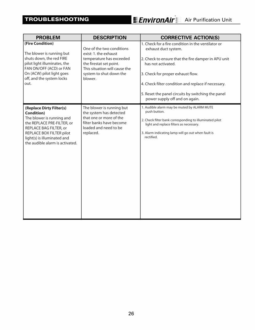
(Fire Condition)
The blower is running but shuts down, the red FIRE pilot light illuminates, the FAN ON/OFF (ACD) or FAN On (ACW) pilot light goes off, and the system locks out.
One of the two conditions exist: 1. the exhaust temperature has exceeded the firestat set point. This situation will cause the system to shut down the blower.
1. Check for a fire condition in the ventilator or exhaust duct system. 2. Check to ensure that the fire damper in APU unit has not activated. 3. Check for proper exhaust flow. 4. Check filter condition and replace if necessary. 5. Reset the panel circuits by switching the panel power supply off and on again.
(Replace Dirty Filter(s)
Condition)
The blower is running and the REPLACE PRE-FILTER, or REPLACE BAG FILTER, or REPLACE BOX FILTER pilot light(s) is illuminated and the audible alarm is activated.
The blower is running but the system has detected that one or more of the filter banks have become loaded and need to be replaced.
1. Audible alarm may be muted by ALARM MUTE push button. 2. Check filter bank corresponding to illuminated pilot light and replace filters as necessary. 3. Alarm indicating lamp will go out when fault is rectified.

28
ASSEMBLY DETAILS & PARTS LIST
AIR MONITOR CABINET PARTS LIST
ITEM DESCRIPTION CARROLL PART NO.
1 Fire Stat, adjustable from 100˚ - 240˚F, SPDT, w/ NEMA 1 APU 6320Enclosure, Remote bulb, mounting clip.
2 Pressure switch, non-adjustable, two ported differential sensor, 0.25” APU 6960W.G., N.O. contacts, solid terminal.
3 Pressure switch, non-adjustable, two ported differential sensor, 0.75” APU 6980W.G., N.O. contacts, solid terminal.
4 Pressure switch, non-adjustable, two ported differential sensor, 1.0” APU 7000W.G., N.O. contacts, solid terminal.
5 Pressure switch, non-adjustable, two ported differential sensor, 1.5” APU 7005W.G., N.O. contacts, solid terminals.
6 Pressure switch, adjustable range 0.05” to 5.0” W.G. APU7010
7 1/4” O.D. x 1/8” I.D. silicone rubber tubing, 50 durometer, translucent tubing, APU 7240temperature range - 80°F to 400°F.
ACW-ACD STATUS PANEL PARTS LIST
8 Transformer, 40 VA, 120 Primary, 24 VAC secondary, foot mount. APU 7180
9 2 amp. Control fuse, ceramic, dual-element. EL22375
10 8 amp. Supply fuse, ceramic, dual-element. EL22414
11 Timer relay, adjustable 1.5 - 60 seconds, 24-VAC. APU 6920
12 Control relay, 3 amps, LED/Neon indicator, 24 VAC coil, 4-pole. APU 6900
13 Push button “FIRE TEST” switch, momentary screw terminal. APU 7020
14 Pilot light assembly, 24 VAC lamp with bezel and bulb (1.2 watts). APU 6880
15 Red lens cover, engraved “FILTER OUT”. APU 6660
16 Red lens cover, engraved “NIL AIR”. APU 6700
17 Red lens cover, engraved “FIRE”. APU 6680
18 Green lens cover, engraved “FAN ON”. (ACW only) APU 6620
19 Green lens cover, engraved “NORMAL”. APU 6640
20 Yellow lens cover, engraved “LOW AIR”. APU 6720
21 Push button “RESET” or “SILENCE BUZZER” switch, momentary 24 VAC APU 7040switch with bezel and bulb (1.2 watt).
Air Purification Unit
27
Fire Stat, non adjustable type.
Pilot light assembly, 24 VAC lamp with bezel and bulb (1.2 watts). APU 6880
Red lens cover, engraved “FILTER OUT”. APU 6660
Red lens cover, engraved “FIRE”. APU 6680
Green lens cover, engraved “FAN ON”. (ACW only) APU 6620
Green lens cover, engraved “POWER ON”.
Push button “RESET” or “SILENCE BUZZER” switch, momentary 24 VAC APU 7040 switch with bezel and bulb (1.2 watt).
APU 7040
Clear lamps, 24 VAC.
APU 6740 Yellow lens cover engraved “RESET”.
APU 6580
Push button “FAN ON/OFF” switch, maintained 24 VAC switch with APU 7030 bezel and bulb (1.2 watt). (ACD only)
APU 7030

29
ASSEMBLY DETAILS & PARTS LIST
ITEM DESCRIPTION CARROLL PARTS NO.
22 Yellow lens cover engraved “RESET”. APU 6740
23 Clear lamps, 24 VAC. APU 6580
24 Push button “FAN ON/OFF” switch, maintained 24 VAC switch with APU 7030bezel and bulb (1.2 watt). (ACD only)
25 Push button “FAN ON/OFF” switch, Lens Green (ACD only) APU 6605
26 Blue lens cover engraved “LOW ODOR SPRAY”. APU 6610
27 Orange lens cover engraved “CONTROL BYPASS”. APU 6650
28 Low Odor Buzzer APU 6030
29 Blue lens cover engraved “SILENCE BUZZER”. APU 6612
30 Red lens cover engraved “REPLACE PRE-FILTER. APU 6705
31 Red lens cover engraved “REPLACE BAG FILTER”. APU 6710
32 Red lens cover engraved “REPLACE BOX FILTER”. APU 6715
FILTER SECTION
33 UL Listed Fuse Link 212°F (100°C) for vertical fire damper. APU 6405
34 Pre-Filter Pleated 24”X24”X2”. APU 6220
35 Pre-Filter Pleated 12”X24”X2”. APU 6200
36 Pre-Filter Pleated 24”X24”X4”. APU 6222
37 Pre-Filter Pleated 12”X24”X4”. APU 6202
38 Bag Filter 24”X24”X22”. APU 6260
39 Bag Filter, 12”X24”X22”. APU 6240
40 Box Filter, 24”X24”X12”. APU 6300
41 Box Filter, 12”X24”X12” APU 6280
42 Static pressure tip with fittings. APU 7160
Air Purification Unit
Push button “FAN ON/OFF” switch, Lens Green (ACD only) APU 6605
Blue lens cover engraved “LOW ODOR SPRAY”. APU 6610
28
Alarm Buzzer APU 6030
Yellow lens cover engraved “ALARM MUTE”. APU 6612
Red lens cover engraved “REPLACE PRE-FILTER. APU 6705
Red lens cover engraved “REPLACE BAG FILTER”. APU 6710
Red lens cover engraved “REPLACE BOX FILTER”. APU 6715
29
30
31
32
33
34
35
36
37

30
ASSEMBLY DETAILS & PARTS LIST
ITEM DESCRIPTION CARROLL PARTS NO.
43 Latch for filter & odor media access doors. APU 6600
44 Bumper foot for item 42 door latch. APU 6601
ODOR SPRAY SECTION
45 5 amp fuse, ceramic dual element. EL22402
46 Timer, Adjustable 15-600 sec., 120 VAC. APU 7120
47 1/8 h.p. air compressor - 120 VAC. APU 6000
48 Atomizing nozzle assembly. APU 6800
49 Foot valve with check valve. APU 7320
50 1/8” 60 PSIG air pressure gauge. APU 6480
51 “T” style door handle. HW50860
52 EnvironSafe 1 case (4 Gallons), (15.1 Liters). APU 8000
53 EnvironSafe 5 Gallon pail, (18.9 Liters). APU 8010
54 EnvironSafe 55 Gallon drum (208.2 Liters). APU 8020
55 Low odor spray level switch. APU 6955
ODOR MEDIA SECTION
56 Odor Media empty steel tray, 12”X24”X2”. APU 7200
57 Odor Media empty steel tray, 24”X24”X2”. APU 7201
58 Alumnia Spheres Impregnated w/ Potassium Permanganate 50lb. Box APU 6820
59 Activated Carbon 55lb. Bag APU 6825
60 50/50 Blend Potassium Permanganate/Activated Carbon 40lb. Box APU 6830
Air Purification Unit
38
39
40
41
42
43
44
45
46
47
48
50
51
52
53
54
55
56
29
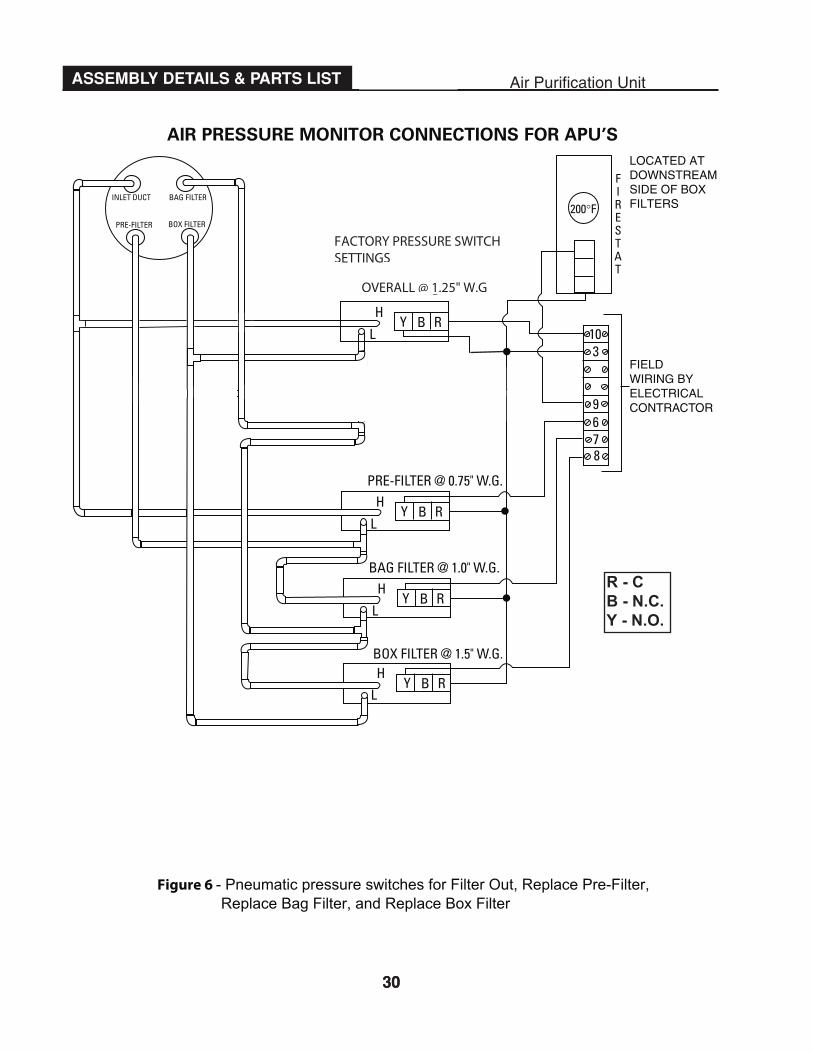
Y B R
FILTER OUT @ 0.25" W.G.H
L
Y B R
PRE-FILTER @ 0.75" W.G. H
L
INLET DUCT BAG FILTER
PRE-FILTER BOX FILTER
200°F
FIRESTAT
10 3
9 6 7 8
H
L
BOX FILTER @ 1.5" W.G.
Y B R
BAG FILTER @ 1.0" W.G.H
L
Y B R
FILTER OUT @ 0.25" W.G.H
L
Y B R
FIELD
LOCATED ATDOWNSTREAMSIDE OF BOXFILTERS
WIRING BYELECTRICALCONTRACTOR
AIR PRESSURE MONITOR CONNECTIONS FOR APU’S
Figure 6- Pneumatic pressure switches for Filter Out, Replace Pre-Filter,Replace Bag Filter, and Replace Box Filter
30
ASSEMBLY DETAILS & PARTS LIST Air Purification Unit
30
FILTER OUT @ 1.25" W.G
R - C B - N.C. Y - N.O.
Figure 6 - Pneumatic pressure switches for Filter Out, Replace Pre-Filter,Replace Bag Filter, and Replace Box Filter
OVERALL @ 1.25" W.G
FACTORY PRESSURE SWITCH SETTINGS
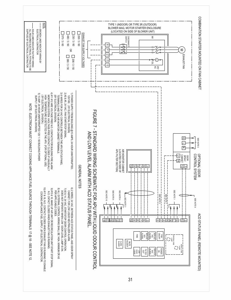
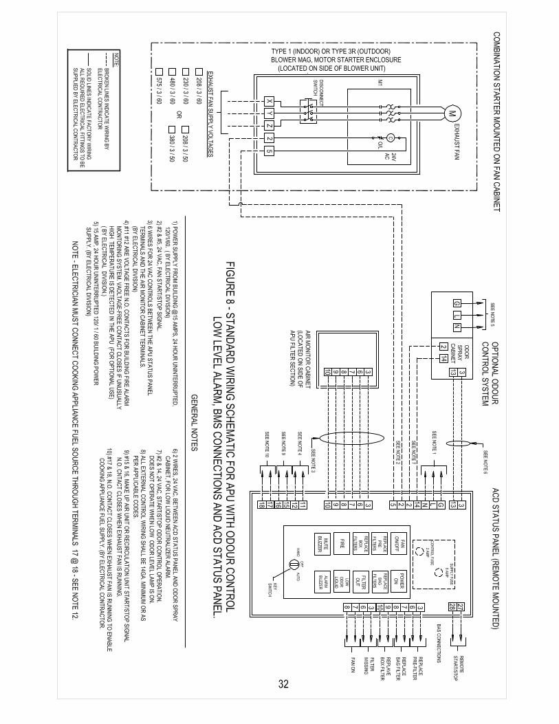

NOTE: FILL OUT AND RETURN TO CARROLL MANUFACTURING INTERNATIONAL®
Job Name:
Location:
Serial Number: Model Number:
Date: Operator:
Complete sections I, IV, VII, IX, and X only if the APU is equipped with the optional fan/blower
section by Carroll.
I. Fan and Drive Assembly Check:
• Before unit is first turned on, check fan assembly for vibration isolator functionality. Remove any
shipping blocks if installed.
• Check fan, motor pulleys, and shafts for proper alignment and adjust if necessary.
• Check belts for proper tension. (See page 23) Adjust pulley distance as may be necessary via the
motor slide base advancement drive screw(s):
II. Filter Compartment Check:
• Are filters in place as per the drawings: Yes:________ No:________
• Are the odor cells filled (IF INSTALLED): Yes:________ No:________
• Complete the following with the quantity of each filter size and type:
• No. Pre-Filters ____________24 X 24 X 4, and ______________24 X 12 X 4 Manufacturer__________
• No. Bag Filters ____________24 X 24 X 22, and______________24 X 12 X 22 Manufacturer_________
• No. Box Filters ____________24 X 24 X 12, and______________24 X 12 X 12 Manufacturer_________
• No. Odor Cells ____________24 X 24 X 2, and ______________24 X 12 X 2 (IF INSTALLED)
III. Verify Firestat Setting of 200°F (93°C) OK_________
IV. Complete Motor and Starter Panel Capacities:
• Motor HP: __________ Motor Voltage: ____________ Fuse Size: __________ Overload Setting: __________
V. Verify ACD or ACW Status Panel Start-Up Proving Timer Setting (Factory Pre-Set at 30 Seconds)
Yes:_____ No:______
VI. Confirm that all Mechanical and Electrical Interconnections are Complete: Yes:_____
36
✁✁
ENVIRONAIR® START-UP REPORT Air Purification Unit
33
Complete Motor and Starter Panel Capacities:
• Motor HP: __________ Motor Voltage: ____________ Fuse Size: __________ Overload Setting: __________
Verify ACD or ACW Status Panel Start-Up Proving Timer Setting (Factory Pre-Set at 30 Seconds)
Yes:_____ No:______
Confirm that all Mechanical and Electrical Interconnections are Complete: Yes:_____
VI. Verify that fuel source to cooking appliances is shut off when APU stops. Yes ____

21
ENVIRONAIR® START-UP REPORT
VII. Check to Ensure that the Fan Shaft Rotational Direction Matches the Direction Arrow on the Fan Housing,
after Momentarily Jogging the Fan Motor.
• Yes:________ No:________ (Notify electrical contractor if “No” is checked)
VIII. Verify that Interconnection Wiring Between ACW or ACD and the Air Monitor Cabinet Have Been
Terminated on the Appropriate Terminals. Refer to the Project Drawings or Schematics at the End of
this Manual.
• Wiring Correct: Yes:________ No:________ (Notify electrical contractor if field wiring appears incorrect)
IX. Measure Full Load Amps and Volts:
• Amps: L1: ________L2: __________L3: __________ Volts: L1: __________L2:__________L3: __________
X. Read Fan RPM: Fan RPM _______________
XI. Odor Spray Cabinet: (IF INSTALLED)
• If Low Odor Spray indicators are provided, check that indicator light illuminates and buzzer and
silence switch perform. Yes:________ No:________
• Fill and insert the 5 gallon (18.9 Liter) Container.
• Check the timer settings:
• Cycle Timer Setting: ____________
• Spray Timer Setting: ____________
• Is the Spray Nozzle operating: Yes: ____________
XII. Remove One Bag Filter and Start the APU, Check for:
• Filter Out Pilot Illuminates: Yes: __________No: __________
• Fan Shuts Off: (after approx. 30 secs.) Yes: __________No: __________
XIII. Remove One Box Filter and Start the APU, Check for:
• Filter Out Pilot Illuminates: Yes: __________No: __________
• Fan Shuts Off: (after approx. 30 secs.) Yes: __________No: __________
Comments: ________________________________________________________________________________________
__________________________________________________________________________________________
__________________________________________________________________________________________
__________________________________________________________________________________________
__________________________________________________________________________________________
Start Up Report Completed By:
Name: __________________________________________Signature: ________________________________________
Company: __________________________________________________________Date: __________________________
Air Purification Unit
(Observed momentarily via Box FilterAccess Door with one Filter removed)
VII. Check to Ensure that the Fan Shaft Rotational Direction Matches the Direction Arrow on the Fan Housing,
after Momentarily Jogging the Fan Motor.
• Yes:________ No:________ (Notify electrical contractor if “No” is checked)
VIII. Verify that Interconnection Wiring Between ACW or ACD and the Air Monitor Cabinet Have Been Terminated on
the Appropriate Terminals. Refer to the Project Drawings or Schematics at the End of this Manual.
• Wiring Correct: Yes:________ No:________ (Notify electrical contractor if field wiring appears incorrect)
IX. Measure Full Load Amps and Volts:
• Amps: L1: ________L2: __________L3: __________ Volts: L1: __________L2:__________L3: __________
X. Read Fan RPM: Fan RPM _______________
XI. Odor Spray Cabinet: (IF INSTALLED)
• If Low Odor Liquid indicators are provided, check that indicator light illuminates and buzzer andsilence switch perform. Yes:________ No:________
• Fill and insert the 5 gallon (18.9 Liter) Container.
• Check the timer settings:
• Cycle Timer Setting: ____________
• Spray Timer Setting: ____________
• Is the Spray Nozzle operating: Yes: ____________
XII. Remove One Bag Filter and Start the APU, Check for:
• Filter Out Pilot Illuminates: Yes: __________No: __________
• Fan Shuts Off: (after approx. 30 secs.) Yes: __________No: __________
XIII. Remove One Box Filter and Start the APU, Check for:
• Filter Out Pilot Illuminates: Yes: __________No: __________
• Fan Shuts Off: (after approx. 30 secs.) Yes: __________No: __________
XIV. External Pressure Drop Readings:
• Upstream P.D. __________
• Downstream P.D. __________
Comments: _______________________________________________________________________________________________________________________________________________________________________
______________________________________________________________________________________________________________________________________________________________________________________________________________________________________________________________________________________________________
Start Up Report Completed By:
Name: __________________________________________Signature: ________________________________________
Company: __________________________________________________________Date: __________________________
__________________________________________________________________________________________________ __________________________________________________________________________________________________ __________________________________________________________________________________________________
VII. Verify that Interconnection Wiring Between ACW or ACD and the Air Monitor Cabinet Have Been Terminated on
VIII. Measure Full Load Amps and Volts:
IX. Read Fan RPM: Fan RPM _______________
X. Odor Spray Cabinet: (IF INSTALLED)
XI. Remove One Bag Filter and Start the APU, Check for:
XII. Remove One Box Filter and Start the APU, Check for:
XIII.
VI. Check to Ensure that the Fan Shaft Rotational Direction Matches the Direction Arrow on the Fan Housing,
34
38
THE CARROLL ENVIRONAIR® AIR PURIFICATION UNIT
LIMITED WARRANTY STATEMENT
The Carroll EnvironAir® Air Purification Unit is warranted to be free from defects inmaterials and workmanship under normal use, when installed and operated, andmaintained in accordance with factory recommendations.
Component parts not manufactured by Carroll Manufacturing or its licensees, such aselectrical switches, solenoid coils, relays and flexible hoses, shall be under the terms andconditions of the warranty as provided by such component parts manufacturers orsuppliers.
The obligation under this warranty, and any warranties implied under the law, shall belimited to repairing or replacing, at Carroll's option, any part of the goods disclosed toCarroll's satisfaction to be defective. This warranty shall remain effective and enforceablefor a period of one (1) year from date of installation, or eighteen (18) months from thedate of shipment, whichever date occurs first. CARROLL SHALL NOT BE HELDRESPONSIBLE FOR ANY INCIDENTAL OR CONSEQUENTIAL DAMAGES RESULTINGFROM A BREACH OF THIS LIMITED WARRANTY.
ITEMS NOT COVERED BY THIS WARRANTY:
1. Routine maintenance such as filter, odor media, and odor neutralizer replacement andperiodic inspection of the unit.
2. Malfunction or improper operation caused by fluctuating electrical power surges,brown outs, or lightning strikes.
3. Misuse of unit’s intended operation or failure to properly maintain.
4. Breakage, wear, or slippage of fan belts and/or failure of electrical fuses and contactpoints.
This is the sole warranty with respect to the Carroll Air Purification Unit. NEITHER CARROLLNOR ANY OTHER PARTY MAKES ANY OTHER WARRANTY OF ANY KIND WHATSOEVER,EXPRESSED OR IMPLIED, AND ALL IMPLIED WARRANTIES OF MERCHANTABILITY ANDFITNESS FOR A PARTICULAR USE WHICH EXCEED THE AFORESAID OBLIGATIONS AREHEREBY DISCLAIMED AND EXCLUDED FROM THIS AGREEMENT.
3435

NOTES
36

(Air Purification Unit)
For Commercial Kitchen Applications
EnvironAir ® is Working in Hundreds of Locations Around the World
to Help Keep Our Environment Cleaner
23 Vreeland Road, Florham Park, New Jersey 07932Phone: 973-966-6000, 800-444-9696
Fax: 973-966-0315Website: www.carrollmi.comEmail: [email protected]
Marlboro Country Club
Marlboro, New Jersey
Queens Quay
Toronto, Canada
University of Toronto
Toronto, Canada
Emirates Towers
Dubai, United Arab Emirates
Aladdin Casino & Hotel
Las Vegas, Nevada
Sel De La Terre Restaurant
Boston, Massachusetts
Photo courtesy of Vegas.com
Air Canada Center
Toronto, Canada
1200 Fewster Drive, Mississauga, Ontario, Canada, L4W 1A1 Phone: 905-731-1050 Fax: 905-731-8547