air formed arch culvert construction · air formed arch culvert final report, ... arch culverts...
TRANSCRIPT
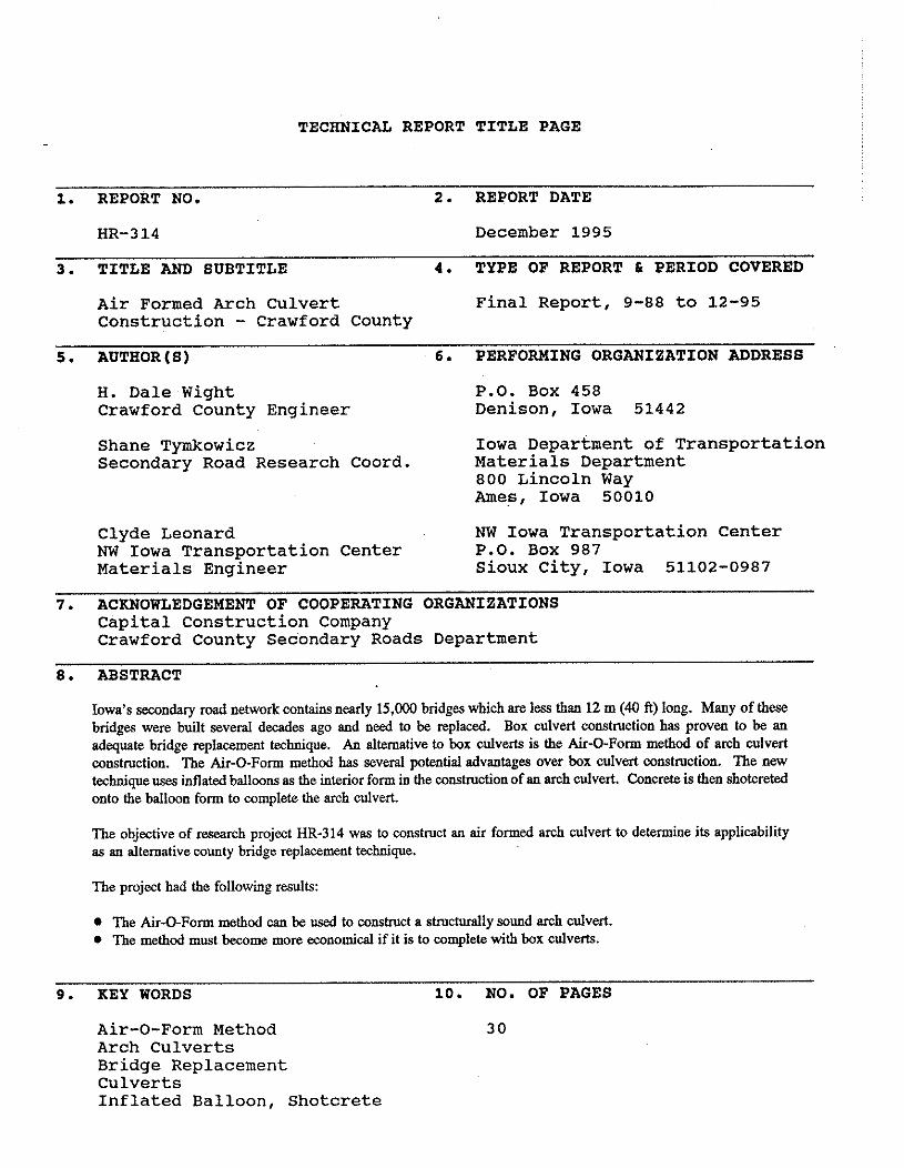
TECHNICAL REPORT TITLE PAGE
1. REPORT NO. 2. REPORT DATE
HR-314 December 1995
3. TITLE AND SUBTITLE 4. TYPE OF REPORT & PERIOD COVERED
Air Formed Arch Culvert Final Report, 9-88 to 12-95 Construction - Crawford County
5 . AUTEOR(8) 6. PERFORMING ORGANIZATION ADDRESS
H. Dale Wight P.O. Box 458 Crawford County Engineer Denison, Iowa 51442
Shane Tymkowicz Iowa Department of Transportation Secondary Road Research Coord. Materials Department
800 Lincoln Way Ames, Iowa 50010
Clyde Leonard NW Iowa Transportation Center NW Iowa Transportation Center P.O. Box 987 Materials Engineer Sioux City, Iowa 51102-0987
7 . ACKNOWLEDGEMENT OF COOPERATING ORGANIZATIONS Capital Construction Company Crawford County Secondary Roads Department
8. ABSTRACT
Iowa's secondary road network contains nearly 15,000 bridges which are less than 12 m (40 ft) long. Many of these bridges were built several decades ago and need to be replaced. Box culvert construction has proven to be an adequate bridge replacement technique. An alternative to box culverts is the Air-0-Form method of arch culvert wnstruction. The Air-QForm method has several potential advantages over box culvert wnstmction. The new technique uses inflated balloons as the interior form in the wnstruction of an arch culvert. Concrete is then shotcreted onto the balloon form to complete the arch culvert.
The objective of research project HR-314 was to construct an air formed arch culvert to determine its applicability as an alternative wunty bridge replacement technique.
The project had the following results:
The Air-QForm method can be used to wnstruct a structurally sound arch culvert. The method must become more economical if it is to complete with box culverts.
9. KEY WORDS 10. NO. OF PAGES
Air-0-Form Method 30 Arch Culverts Bridge Replacement Culverts Inflated Balloon, Shotcrete
FINAL REPORT IOWA HIGHWAY RESEARCH BOARD
PROJECT HR-3 14
AIR FORMED ARCH CULVERT CONSTRUCTION CRAWFORD COUNTY
H. Dale Wight, P.E. Crawford County Engineer
7 12-263-2449
and
Clyde Leonard, P.E. Materials Engineer
712-276-0933 Northwest Iowa Transportation Center
Iowa Department of Transportation
and
Shane Tyrnkowicz Secondary Road Research Coordinator
515-239-1382 Iowa Department of Transportation
Project Development Division Office of Materials Ames, IA 50010
December 1995
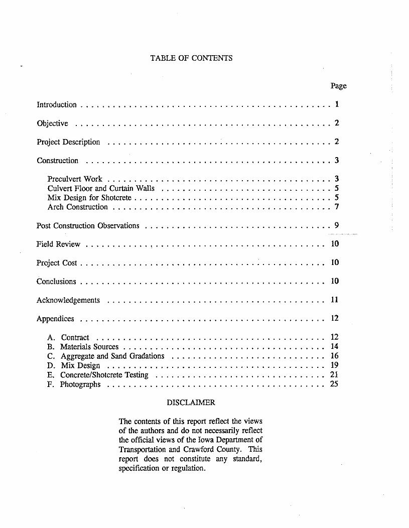
TABLE OF CONTENTS
Page
Introduction . . . . . . . . . . . . . . . . . . . . . . . . . . . . . . . . . . . . . . . . . . . . . . . 1
Objective . . . . . . . . . . . . . . . . . . . . . . . . . . . . . . . . . . . . . . . . . . . . . . . . 2
. . . . . . . . . . . . . . . . . . . . . . . . . . . . . . . . . . . . . . . . . . Project Description 2
Construction . . . . . . . . . . . . . . . . . . . . . . . . . . . . . . . . . . . . . . . . . . . . . . 3
PreculvertWork . . . . . . . . . . . . . . . . . . . . . . . . . . . . . . . . . . . . . . . . . . 3 Culvert Floor and Curtain Walls . . . . . . . . . . . . . . . . . . . . . . . . . . . . . . . . 5 Mix Design for Shotcrete . . . . . . . . . . . . . . . . . . . . . . . . . . . . . . . . . . . . . 5 Arch Construction . . . . . . . . . . . . . . . . . . . . . . . . . . . . . . . . . . . . . . . . . 7
. . . . . . . . . . . . . . . . . . . . . . . . . . . . . . . . . . . Post Construction Observations 9
Field Review . . . . . . . . . . . . . . . . . . . . . . . . . . . . . . . . . . . . . . . . . . . . . 10
Project Cost . . . . . . . . . . . . . . . . . . . . . . . . . . . . . . . . . . . . . . . . . . . . . . 10
. . . . . . . . . . . . . . . . . . . . . . . . . . . . . . . . . . . . . . . . . . . . . . Conclusions 10
Acknowledgements . . . . . . . . . . . . . . . . . . . . . . . . . . . . . . . . . . . . . . . . . 11
Appendices . . . . . . . . . . . . . . . . . . . . . . . . . . . . . . . . . . . . . . . . . . . . . . 12
A . Contract . . . . . . . . . . . . . . . . . . . . . . . . . . . . . . . . . . . . . . . . . . . 12 B . Materials Sources . . . . . . . . . . . . . . . . . . . . . . . . . . . . . . . . . . . . . . 14 C . Aggregate and Sand Gradations . . . . . . . . . . . . . . . . . . . . . . . . . . . . . 16 D . MixDesign . . . . . . . . . . . . . . . . . . . . . . . . . . . . . . . . . . . . . . . . 19 E . Concrete/Shotcrete Testing . . . . . . . . . . . . . . . . . . . . . . . . . . . . . . . . 21 F . Photographs . . . . . . . . . . . . . . . . . . . . . . . . , . . . . . . . . . . . . . . . 25
DISCLAIMER
The contents of this report reflect the views of the authors and do not necessarily reflect the official views of the Iowa Department of Transportation and Crawford County . This report does not constitute any standard. specification or regulation .
INTRODUCTION
Iowa's secondary road network contains nearly 15,000 bridges which are less than
12 m (40 ft) long. Many of these bridges were constructed several decades ago and are now
becoming either structurally deficient or functionally obsolete.
One method often used to replace such a bridge is to construct a single or multiple box culvert.
This type of wnstruction has proved to be an adequate replacement for bridges. However, box
culvert wnstruction can be expensive and time consuming. Construction is slowed because
forms cannot be removed and reused until the poured concrete reaches an acceptable strength.
An alternative to box culverts is the Air-0-Form method of arch culvert construction. The
Air-0-Form technique uses an air inflated balloon as the inside form for the construction of an
arch shaped culvert. The balloon can be inflated quickly, saving time the contractor would
otherwise spend forming the box culvert. The balloon used can also be made to fit a variety of
shapes and sizes.
The arch shape offers several advantages over a box. First, the arch is structurally more
efficient than the box. A culvert of greater strength can be constructed using less steel and
concrete. Also, the arch can be hydraulically more efficient. A third advantage is the absence
of a wall in the center of the structure such as found in multiple box culverts. This eliminates
an obstruction and allows debris to flow through the structure.
The Air-0-Form method of arch culvert construction involves the following six steps. -
1. Placement of a reinforced bottom slab or footing.
2. Placement of flexible metal straps in the desired shape of the arch and inflation of the balloon form. (The straps hold the balloon form in the desired shape.)
3. Placement of longitudinal and vertical steel reinforcement around the inflated form.
4. Adjustment of the air pressure inside the form to the required pressure.
5. Application of 150 mm (6 in) or more of shotcrete in one lift.
6. Deflation and removal of the balloon form once the shotcrete has gained the necessary , strength.
0B.TECTIVE
The objective of this research project was to construct an air formed arch culvert to determine
its applicability as an alternative county bridge replacement technique. Specific topics to be
researched include:
1. The cost and time savings that may be realized using the air form technique.
2. The strength and durability properties of the shotcrete used in the structure.
3. The long term structural capacity of the arch.
PROJECT DESCRJFTION
The location selected (Figure 1) for installation of the air formed arch culvert was the eastern
most of two bridges located on a granular surfaced road in Crawford County separating sections
twelve and thirteen in Nishnabotna Township (12 & 13-82N-38W). The bridge it replaced could
2
no longer safely support the heavy farm equipment loads. Also, during heavy rains, the creek - occasionally rose above the bridge deck making travel hazardous.
The arch culvert was designed to drain a 385 ha (950 acre) area in southeastern Crawford
County. Hydraulic caiculations showed a culvert end area of 10.2 m2 (1 10 sq ft) was needed
to carry the peak water flow from a 25-year flood. Based on this information, a semicircular
arch having a 2.7 m (9 ft) radius and a culvert length of 16 m (52 ft) was needed to meet
roadway width requirements.
CONSTRUCTION .
Capital Construction Company, Inc. of Logan, Iowa was awarded the contract to construct the
arch culvert. A copy of the contract is in Appendix A.
PreCuivert Work
Before the contractor began constructing the culvert, bridge removal and excavating work were
required. The contractor began to remove the existing 7.3 m x 4.9 m (24 ft x 16 ft) bridge and
abutments on October 10, 1990 and all the excavation work was completed by October 16, 1990.
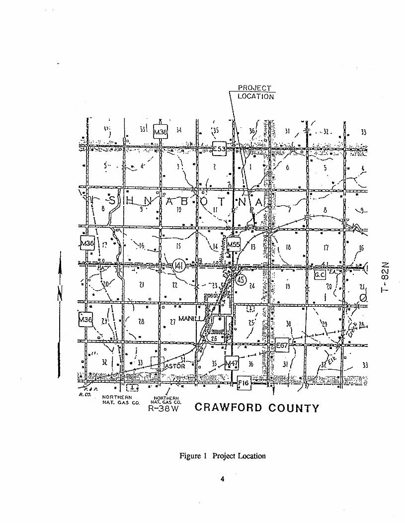
PROJECT
NORTHERN I
NORTHiRN NAT. GAS GO. NAT- GAS CO.
R-3aw CRAWFORD COUNTY
Figure 1 Project Location
4
Culvert Floor and Curtain Walls
On October 22, 1990 the contractor began work constructing the arch culvert. Although the
contractor had experience in other types of concrete work, this was the first experience of
constructing a culvert by shotcrete, a pneumatically applied concrete mix. Forms for the inlet
and outlet curtain walls were placed as well as the reinforcing steel for the pour made later in
the day.
The following two days were spent placing the forms and reinforcing steel for the footing. With
the steel in place on bar chairs and correctly spaced, the pour was made and later covered with
wet burlap for proper curing.
Design for Shotcrete
The original mix design gradation submitted was compared to American Concrete Institute
(A.C.I.) 506.2-77 Rev 83 Part 2 Table 2.2.1 gradation No. 2 and was found to be low on
material passing the No. 50 sieve and No. 100 sieve. This was pointed out to the shotcrete
subcontractor. 45 kg (100 lbs) of fly ash was then added to improve the pumpability of the fine
mix. According to the applicator, it is desirable to have 15-16% passing the No. 50 sieve and
4% passing the No. 100 sieve, or a minimum of 20% passing the No. 50 and No. 100 sieves
combined. Materials sources are listed in Appendix B.
Due to the A.C.I. gradation demands and the availability of produced material that would
provide the combined grading needed, mortar sand, concrete sand, and 13 mm (112 in) coarse
gravel were required in the mix. Hosteng Ready Mix Company, Denison, only had 2 bin
capability for aggregate proportioning. The problem was solved by proportioning the mortar
sand (60%) and concrete sand (40%) through the ready mix plant and blending them in a transit
mixer. The pre-blended sand was then stockpiled for proportioning into the shotcrete mix along
with the 13 mm (112 in) gravel using 70% blended sand and 30% 13 mm (112 in) gravel. The
final gradations and mix design are given in Appendices C and D.
Samples of shotcrete were obtained at the transit mixer discharge chute prior to pumping and
also from 760 mm x 760 mm (30 in x 30 in) shotcrete applied test panels that were 200 mm
(8 in) thick. The samples were obtained from the shotcrete applied panels for the full depth of
the application. All testing of the plastic concrete was then accomplished following Iowa
Department of Transportation Instruction Memorandum (I.M.) testing procedures.
Comparisons were made between the air content of the shotcrete applied concrete and the air
content of the shotcrete mix prior to pumping. The percent air loss due to application ranged
from 1.2% to 1.5%. The same comparison was made for the slump change in the shotcrete.
There was a range of 25 mm to 45 mm (1 in to 1 314 in) slump reduction in the applied
shotcrete mix. Two test panels with reinforcing conforming to the design spacing were made
up with shotcrete applied approximately 200 mm (8 in) thick. The first panel was evaluated for
reinforcing embedment immediately after shotcrete was applied. This was accomplished by
carefully removing the plastic concrete and visually inspecting for dense concrete around the
reinforcing. The second test panel was allowed to set overnight. Two wres were then cut from
the panel. One core was through the reinforcing bars near their intersection and the second core
was through a single reinforcing bar.
Visual examination showed very good embedment of the bars in both cores. Directly below the
reinforcing bar intersection there appeared to be a reduction in warse aggregate in the applied
shotcrete. This was probably due to rebound loss of coarse aggregate striking the reinforcing
during shotcrete application.
Arch Construction
Once the floor and curtain walls were completed, the contractor began work on the air formed
arch.
The fist step in this process was to bolt a perforated angle iron on each side of the floor at the
location where the floor meets the arch. Metal straps were then cut to the desired length and
attached to the angle irons through the perforations. The steel straps hold the inflated balloons
in the desired arch shape. The contractor also widened and lengthened the excavated area to
accommodate the 24 m (80 ft) long balloons.
After inflating both balloons, it was noticed that one had several holes, possibly caused by the
reinforcing bars at the site, and the Air-0-Form subcontractor decided to use just one balloon
for the arch shape. Consequently, the single balloon was expected to stretch 5% more than
normal causing the sides of the balloon to roll away from the reinforcing cage. Plywood boards
placed along the sides provided a surface to shotcrete against, somewhat compensating for this
problem.
After inflating the balloon to an air pressure of 5.7 kPa (0.83 psi), the contractor began placing
reinforcing steel. Number 4 bars were used for longitudinal steel reinforcement and were placed
at 190 mm (7.5 in) spacings. Number 5 bars were then used for transverse reinforcement and
spaced 100 mm (4.0 in) apart. The reinforcement was set away from the balloons by strings
of steel chairs placed around the arch. The entire operation, from positioning the deflated
balloons to finishing placing the reinforcing steel, took two days. Once the steel was in place
the arch was ready to be shotcreted.
On Thursday, November 1, 1990 the arch culvert was shotcreted. Two crews consisting of a
nozzleman and blow pipe operator worked on opposite sides of the arch in order to keep the
weight of the shotcrete evenly distributed around the balloon. Shotcrete was applied full depth
approximately 2.1 m (7.0 ft) high along the length of the culvert. A two hour set-up time was
allowed for this first section and then the top of the culvert was completed by shotcreting from
a mobile platform. The entire process took approximately eight hours.
Crawford County and Iowa DOT personnel were present and performed testing throughout the
shotcreting operation. Test results are listed in Appendix E.
After the arch was completed, the contractor applied a white pigment curing compound by
Dayton Superior and covered the arch with insulated blankets. The balloon was kept inflated
while the arch developed enough strength to support itself. A determination was made by
8
Crawford County to keep the balloon inflated until a shotcrete compressive strength of 11,720
kPa (1700 psi) was reached as determined from cylinders made at the beginning of the
shotcreting operation. This requirement was met in one day, and on November 2, 1990 the
balloon was deflated and removed.
Work on excavation for the east culvert headwalls began on November 5, 1990. It was slow
going as a result of light rain, snow and muddy conditions at the site over a period of days. The
contractor worked on moving the temporary 250 mm (10 in) P.V.C. culvert utilized in diverting
the running creek water in order to excavate material for construction of the west culvert
headwalls. With the forming and reinforcement in place, the headwalls were poured and
covered with insulated blankets. The county then backtilled the culvert with a mix of dry dirt
and gravel, compacting it with the aid of a bulldozer. The project was completed on
November 21, 1990.
POST CONSTRUCTION OBSERVATIONS
After the balloon was removed, the interior of the arch could be observed. Two relatively large
cracks had already appeared, one on each side of the arch approximately 2.1 m (7.0 ft) above
the floor. These cracks ran nearly the length of the culvert. One reason may be that these
cracks were the result of cold joints which formed while the first shotcrete sequence was allowed
to set-up and harden. Another explanation could be that the shotcreting operation was done at
more of an angle than should have been done, because the work platform could not extend
properly from where it was located, and this inhibited the blow pipe operator from doing his job
well. These defects should not damage the structural integrity of the arch. Since any load
applied would result in compression of the concrete, the horizontal cracks should close. These
cracks were subsequently repaired with a non-shrinking grout.
mELD REVIEW
Visual examinations were performed on the Air-0-Form arch culvert annually. The
examinations found the culvert to be structurally sound. The cracks that were formed during
construction show some staining from water seepage (see photo 7 and 8 in Appendix F). The
culvert allows free flow of water and debris. Photo 9 in Appendix F shows the culvert in July
of 1993. Note the lack of debris or blockage of flow in the culvert and seeambed.
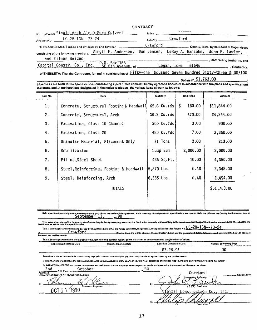
PROJECT COST
The contract price for the Air-0-Form semicircular arched culvert was $51, 673. The culvert
was 16 m (52 ft) long with a 2.7 m (9 ft) radius. The price included the footing and headwall.
A copy of the contract and bid prices is in Appendix A, page 12.
CONCLUSIONS
The objective of this research was to demonstrate the applicability of the Air-0-Form method
of arch culvert construction. In this respect, the project was successful. However, the claim
of being faster and less costly than normal box culvert construction techniques were not met.
The contractors bid was more than $10,000 over the cost estimate for a similar sized box
culvert. One possible reason for the higher cost may have been the research nature of the
project; this was only the second Air-0-Form arch culvert built in the state of Iowa and both
culverts were built by different contractors. The Air-0-Form method may be more economically
favorable for larger diameter and longer culverts. The strength and durability properties of the
shotcrete used in the structure were acceptable. However, precautions should be taken so cold
joints will not form during construction. The arch culvert has provided good service to date.
The long-term structural capacity of the arch appears to be good, but only time will allow an
accurate estimate of design life.
ACKNOWLEDGEMENTS
This research project was sponsored by Crawford County and the Iowa Department of
Transportation through the Iowa Highway Research Board. Partial funding for this project was
from the Secondary Road Research Fund in the amount of $16,500.
The authors wish to extend appreciation to the Crawford County Board of Supervisors and the
Iowa DOT for their support in developing and conducting this project. The Crawford County
and Iowa DOT Northwest Iowa Transportation Center inspection personnel, Capital Construction
Company, and Concepts in Concrete also deserve recognition for the extra effort put forth on
this project.
Appendix A Contract
maacnut. m.aunc.o~ ,nil contract .M uut uacont,uc ca~.dme .II ~ t n i.trns .~~COM*MI .Q,.*I YW WIN pl(t*. w m o .
t t i r &no., uur.ruwa INI ~ O I C M ~ ~ ~ S I W ~onsaots 10 ,n~&o. tbn ot ~M-S a 101.10 war. d.<.m4n M < . o w ~~wmnool u ur .nfwtra.arrrismg ~ U U M $ < .
IN WITNESS WHEREOF the pan-r harat0 Mr. ml mace NMr (of I N p l r - N,.in trP8uW la mb md UrW Oth.< hltwmntl ot L.unOl. u Ol uu
2nd a," ,, October AI)P,o*eC
CONTRACT
Ki, ol,,, , Single Arch Air-O-Form Culvert ------
Miief
Projoct No. - LC-28-13N--73-24 Cwnty Crawford
THIS AGREEMENT made and entered by and between Crawford County, Iowa. by its Board 01 ~ u p e ~ ~ i ~ ~ , ~
consisting OI the tollowing members: Virgil E. Anderson, Don Jensen, LeRoy A. Hansohn, John P. Lawler, and Eileen Heiden
I COntraCllng Authority, and
Capital Constr. Co., Inc. P~:!'RB&ot Loqan, Iowa 51546 . Contractor.
WITNESSETH: That the Contractor, tor and in consideration 01 Fi fty-one Thousand Seven Hundred Sixty-three & 00/100 ~ o i ~ a c s (t 51.763.00 )
payebl~ as set 10nh in the Bpebilications constiluting a pan of Ulis contract. hereby aprees to construct b accordance with the plan* and rpecllicationr Iherelore. and in the locations derignaled in the notice to bidders, the various items 01 work as loitows:
Item No.
1.
2.
3.
4.
5.
6.
7.
8.
9.
September 11, ,a 90 ~ ( u ~ h m ~ 1 ~ r ~ t ~ n r r 1 t n n 1 1 1 1 o a a g . t w ~ ~ ~ ~ ~ ~ 1 i ~ * u t ~ ~ ~ r ~ ~ ~ . p r ~ w p . r 1 ~ ~ o n v ~ ~ . p r o m p n r ~ 1 d ~ ~ ~ ~ h g ~ ~ u ~ w r * ( r * ( 1 1 d ~ u 1 p a 1 i u t i w ~ * ~ ~ ~ ( 1 ~ h 1 ~ ~ r 1 1 ~ ~ ~
Sondilb". U "tIM" yl VU Iplu,,sUi~'.
muit*nvtvruruwntoaa . n ~ q ~ w d b ~ U u w ~ N I ~ e Y u l U * I D ( U t O - r ~ . w P - . Y * w i l ~ ~ c ~ . h x P , ~ M . LC-28-13N--73-24 4" Crawford C O ~ ~ ~ ~ . ~ . ~ ~ M ~ ~ ~ N ~ ~ ~ ~ ~ I . ~ M ~ ~ ~ ~ ~ ~ ~ ~ ~ M ~ C ~ ~ ~ U * ~ U M ~ ~ . I . U ~ P I ~ ~ Y ~ . M O W I ~ U I ~ M M ~ ~ ~ ~ ~ ~ ~ I ~ ~ ~ P l t r m m. PM*. lW.10.
Itdm
Concrete, Structural Footing & Headwall
Concrete, Structural, Arch
Excavation, Class 10 Channel
Excavation', Class 20
Granular Material, Placement Only
Mobilization
Piling,Steel Sheet
steel ,Reinforcing, Footing & Headwall
Steel, Ref nforcing, Arch
TOTALS
~ . i .spct t iea t i rn .ndp~a~~ or.nu..y nu-. p m o t o ~ i w ~ r i s o ( t l ~ ~ ~ ~ ~ I . ~ M ~ ~ ~ u ~ P ~ ~ u w P ~ u ) ~
Amwnl
$11.844.00
24.254.00
900.00
3,360.00
213.00
2,000.00
4,350.00
2,348.00
2,494.00
$51,763.00
. ~ ( p c ( t i u t i w u ~ n o r a w . ~ ~ w ~ ~ ~ ~ ~ ~ ~ ~ ( * w u ~ ~ ~ ~ m ~ ~ ~ ~ ~ o ~
Ovlntily
65.8 Cu.Yds
36.2 Cu.Yds
300 Cu.Yds
480 Cu.Yds
71 Tons
Lump Sum
435 Sq.Ft.
5,870 Lbs.
6,235 Lbs.
Unlt Priw
$ 180.00
670.00
3.00
7.00
3.00
2,000.00
10.00
0.40
0.40
Appendix B Material Sources

AGGREGATES
Iowa DOT Specific Iowa DOT T v ~ e Prod. Svec. Gravitv Source No. Source Name
Mortar Sand 4112-2 2.64 A-81504 Hosteng Conc. & Gravel, Auburn, IA
Concrete Sand 4110-1 2.67 A-81528 Carnarvon Sand & Gravel, Wall Lake1 Pittman
112" Gravel 4115 * 2.70 A-81502 Hallett Materials, Lake View
*Gradation used in pre-cast pipe production
1 inch = 25.4 mrn
CEMENT
AASHTO Specific Material 2 E Z Gravity Producer
Fly Ash C 2.55 Port Neal 4, Sioux City, IA Portland Cement I 3.14 Monarch Cement Co.
Material Brand Producer
Air Entraining Prokrete AES Water Reducer Prokrete N-3
Prokrete Ind. Lot No. 25359 Prokrete Ind. Lot No. 25360
Appendix C Aggregate and Sand Gradations
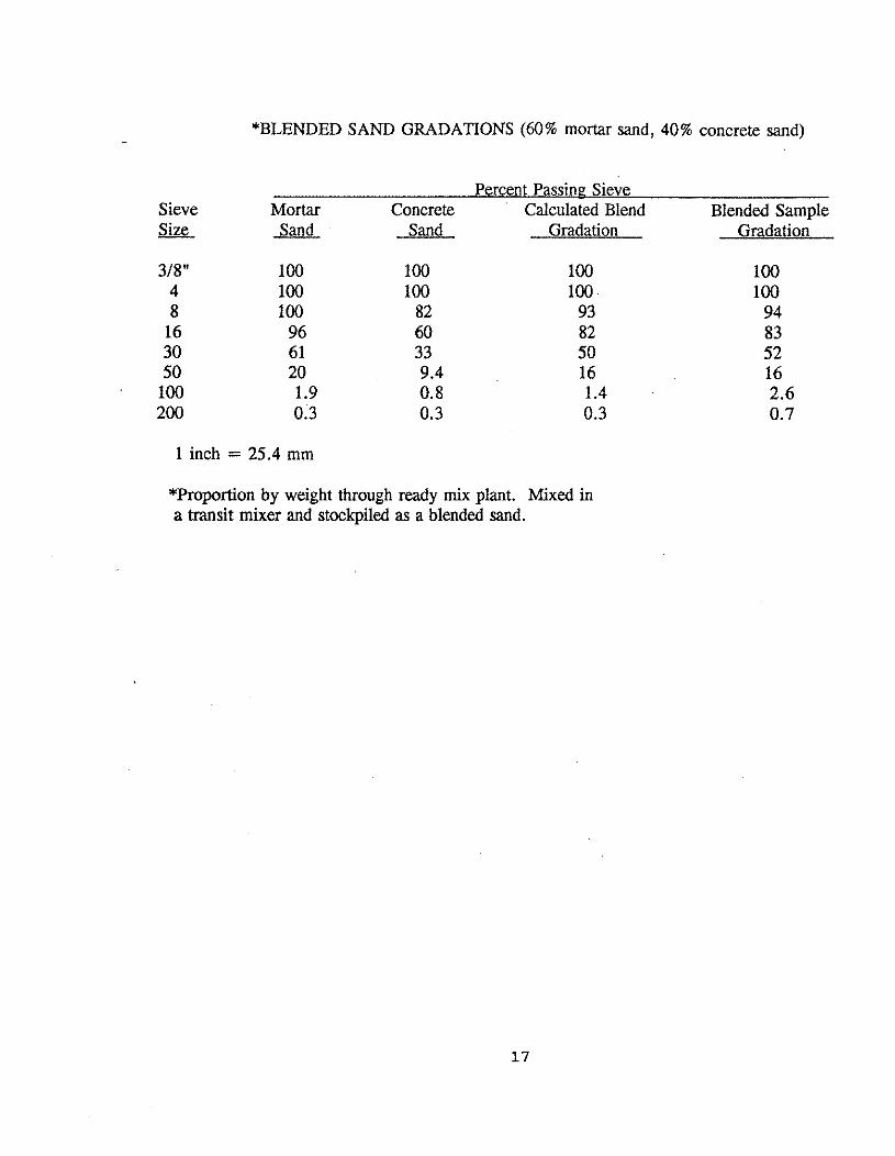
*BLENDED SAND GRADATIONS (60% mortar sand, 40% concrete sand)
Percent Passine Sieve Sieve Mortar Concrete Calculated Blend Blended Sample size Sand Gradation Gradation
1 inch = 25.4 mm
*Proportion by weight through ready mix plant. Mixed in a transit mixer and stockpiled as a blended sand.
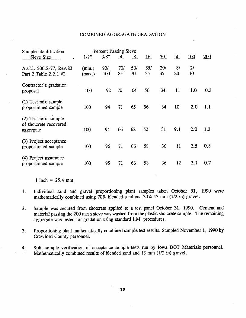
COMBINED AGGREGATE GRADATION
Sample Identification Percent Passing Sieve Sieve Size 1 / 2 " 3 / 8 " Q _ 8 1 6 - 3 0 1 1 Z r ! m
A.C.I. 506.2-77, Rev.83 (min.) 901 701 501 351 201 81 21 Part 2,Table 2.2.1 #2 (max.) 100 85 70 55 35 20 10
Contractor's gradation ~ r o p 0 4 100 92 70 64 56 34 11 1.0 0.3
(1) Test mix sample proportioned sample 100 94 71 65 56 34 10 2.0 1.1
(2) Test mix, sample of shotcrete recovered aggregate 100 94 66 62 52 31 9.1 2.0 1.3
(3) Project acceptance proportioned sample 100 96 71 66 58 36 11 2.5 0.8
(4) Project assurance proportioned sample 100 95 71 66 58 36 12 2.1 0.7
1 inch = 25.4 mm
1. Individual sand and gravel proportioning plant samples taken October 31, 1990 were mathematically combined using 70% blended sand and 30% 13 mm (112 in) gravel.
2. Sample was secured from shotcrete applied to a test panel October 31, 1990. Cement and material passing the 200 mesh sieve was washed from the plastic shotcrete sample. The remaining aggregate was tested for gradation using standard I.M. procedures.
3. Proportioning plant mathematically combined sample test results. Sampled November 1, 1990 by Crawford County personnel.
4. Split sample verification of acceptance sample tests run by Iowa DOT Materials personnel. Mathematically combined results of blended sand and 13 mm (112 in) gravel.
Appendix D Mix Design
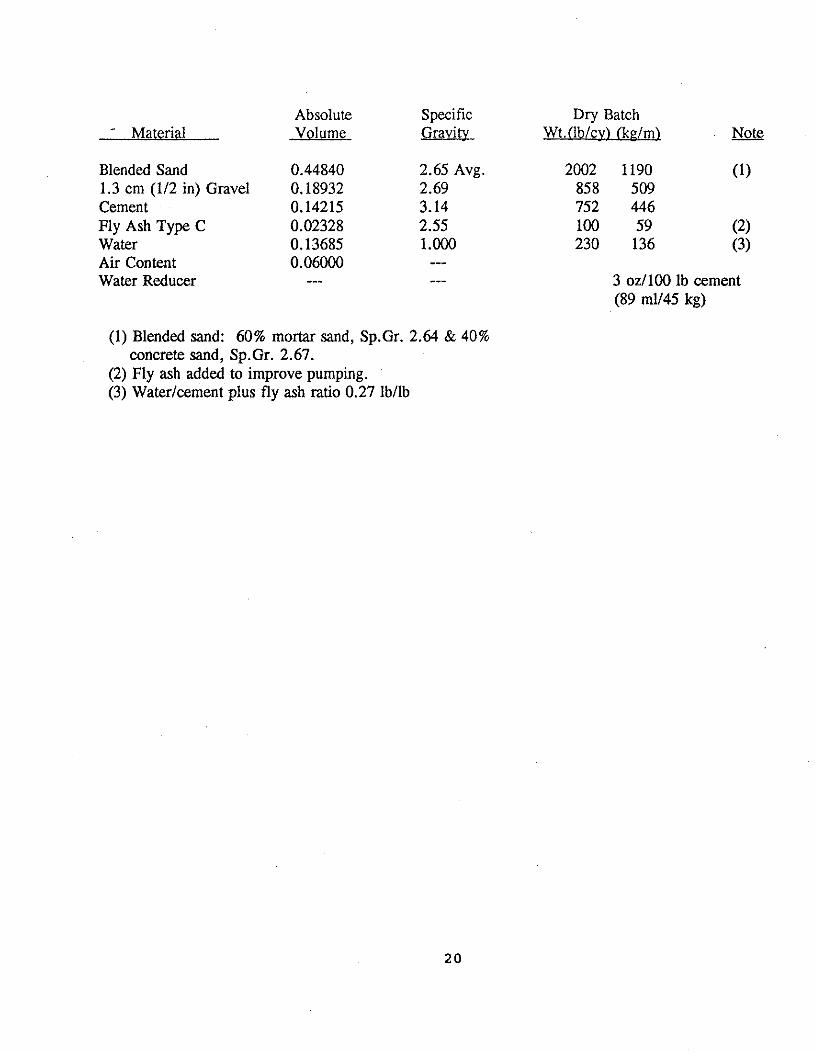
Absolute Specific * Material Volume Gravity
Blended Sand 0.44840 2.65 Avg. 1.3 cm (112 in) Gravel 0.18932 2.69 Cement 0.14215 3.14 Fly Ash Type C 0.02328 2.55 Water 0.13685 1.000 Air Content 0.06000 --- Water Reducer --- ---
(1) Blended sand: 60% mortar sand, Sp.Gr. 2.64 & 40% concrete sand, Sp.Gr. 2.67.
(2) Fly ash added to improve pumping. (3) Waterlcement plus fly ash ratio 0.27 lbllb
Dry Batch Wt.(lb/cy) (kplm) .
3 ozllOO lb cement (89 mu45 kg)
Appendix E Concrete/Shotcrete Testing
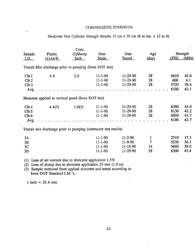
COMPRESSIVE STRENGTH
Shotcrete Test Cylinder Strength Results 15 crn x 30 cm (6 in dia. x 12 in 0)
Conc. Sample Plastic (2)Slump Date Date Age Strength I.D. (l)Air% Inch Made Tested id.& PSI) (MPa)
Transit Mix discharge prior to pumping (Iowa DOT test)
CB- 1 5.9 2.0 11-1-90 11-29-90 28 6610 45.6 CB-2 11-1-90 11-29-90 28 600 4.1 CB-3 11-1-90 1 1-29-90 28 5720 39.4
Avg. . . . . . . . . . . . . . . . . . . . . . . . . . . . . . . . . . . . . . . . . . . . . . 6100 42.1
Shotcrete applied to vertical panel (Iowa DOT test)
CB-4 4.4(3) 1.0(3) 11-1-90 1 1-29-90 28 6380 44.0 CB-5 11-1-90 1 1-29-90 28 6130 42.2 CB-6 11-1-90 11-29-90 28 6050 41.7
. . . . . . . . . . . . . . . . . . . . . . . . . . . . . . . . . . . . . . . . . . . Avg. 6190 42.7
Transit mix discharge prior to pumping (contractor test results)
(1) Loss of air content due to shotcrete application 1.5% (2) Loss of slump due to shotcrete application 25 mrn (1.0 in) (3) Sample removed from applied shotcrete and tested according to
Iowa DOT Standard I.M.'s.
1 inch = 25.4 mm
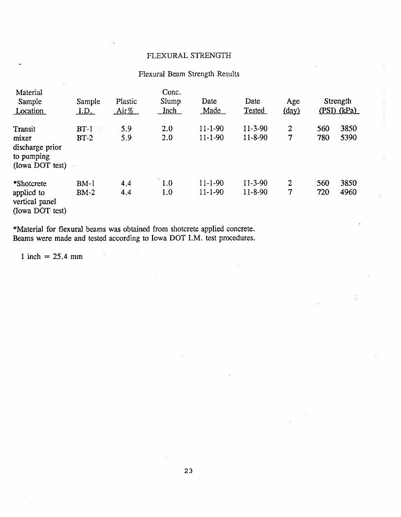
FLEXURAL STRENGTH
Flexural Beam Strength Results
Material Conc. Sample Sample Plastic Slump Date Date Age Strength
Location I.D. Air% Inch Made Tested (dav) PSI) &Pa)
Transit BT- 1 5.9 2.0 11-1-90 1 1-3-90 2 560 3850 mixer BT-2 5.9 2.0 11-1-90 11-8-90 7 780 5390 discharge prior to pumping (Iowa DOT test)
*Shotcrete BM- 1 4.4 1 .O 11-1-90 1 1-3-90 2 560 3850 applied to BM-2 4.4 1 .O 11-1-90 11-8-90 7 720 4960 vertical panel (Iowa DOT test)
*Material for flexural beams was obtained from shotcrete applied concrete. Beams were made and tested according to Iowa DOT I.M. test procedures.
1 inch = 25.4 mm
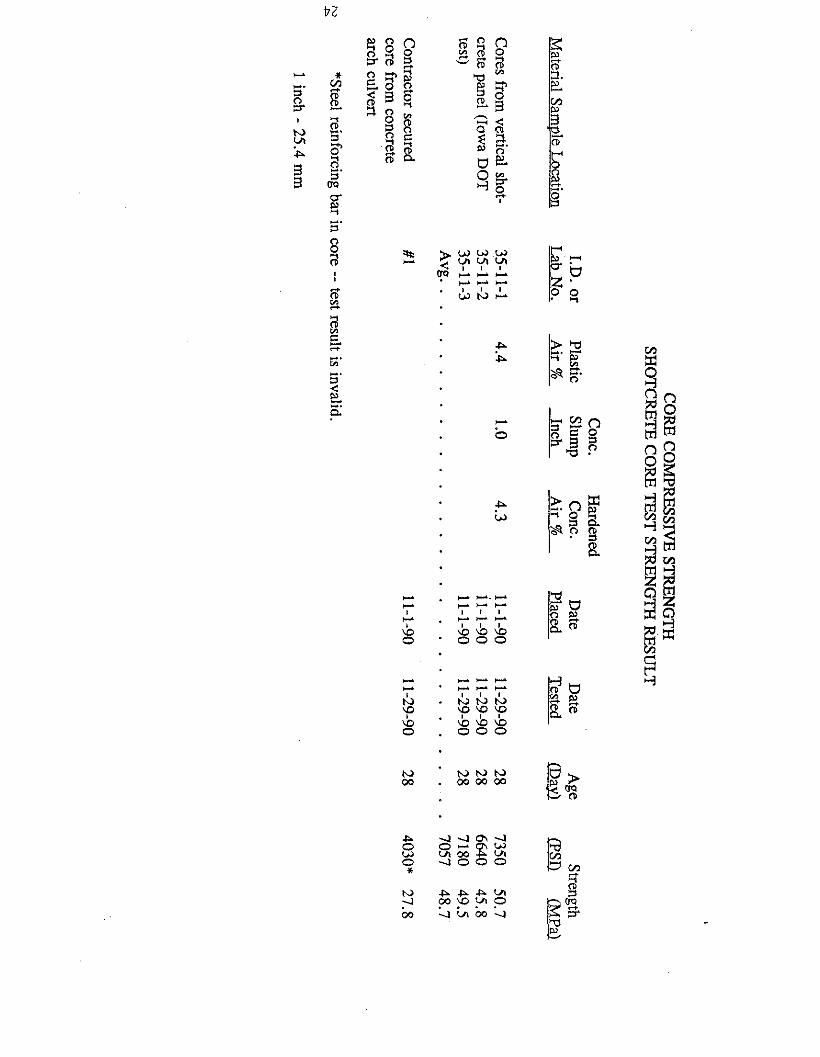
CO
RE
CO
MPR
ESSIV
E ST
RE
NG
TH
SH
OT
CR
ET
E C
OR
E T
EST
STR
EN
GT
H RESULT
Conc.
Hardened
I.D. or
Plastic Slum
p C
onc. D
ate D
ate A
ge Strength
Material Sam
vle Location
Lab N
o. A
ir %
Inch A
ir %
Placed T
ested (D
ayl
(MP
a)
Cores from
vertical shot- 35-11-1
4.4 1.0
4.3 11-1-90
11-29-90 28
7350 50.7
crete panel (Iowa D
OT
35-11-2
il-1-90 11-29-90
28 6640
45.8 test)
35-11-3 11-1-90
11-29-90 28
7180 49.5
Avg..
. . . . . . . . . . . . . . . . . . . . . . . . . . . . . . . .
7057 48.7
Contractor secured
#1 core from
concrete arch culvert
N
P
*Steel reinforcing bar in core -- test result is invalid.
1 inch - 25.4 mm
Appendix F Photographs
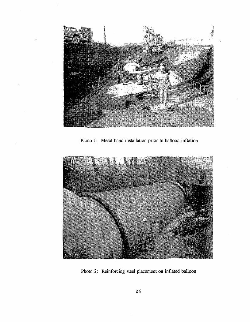
Photo 1: Metal band installation prior to balloon inflation
Photo 2: Reinforcing steel placement on inflated balloon
26

Photo 3: First stage of shotcreting operation
Photo 4: Completing shotcreting operation
27
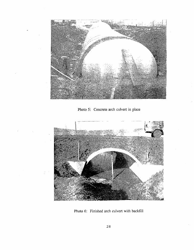
Photo 5 Concrete arch culvert in place
Photo 6: Finished arch culvert with backfill
2 8
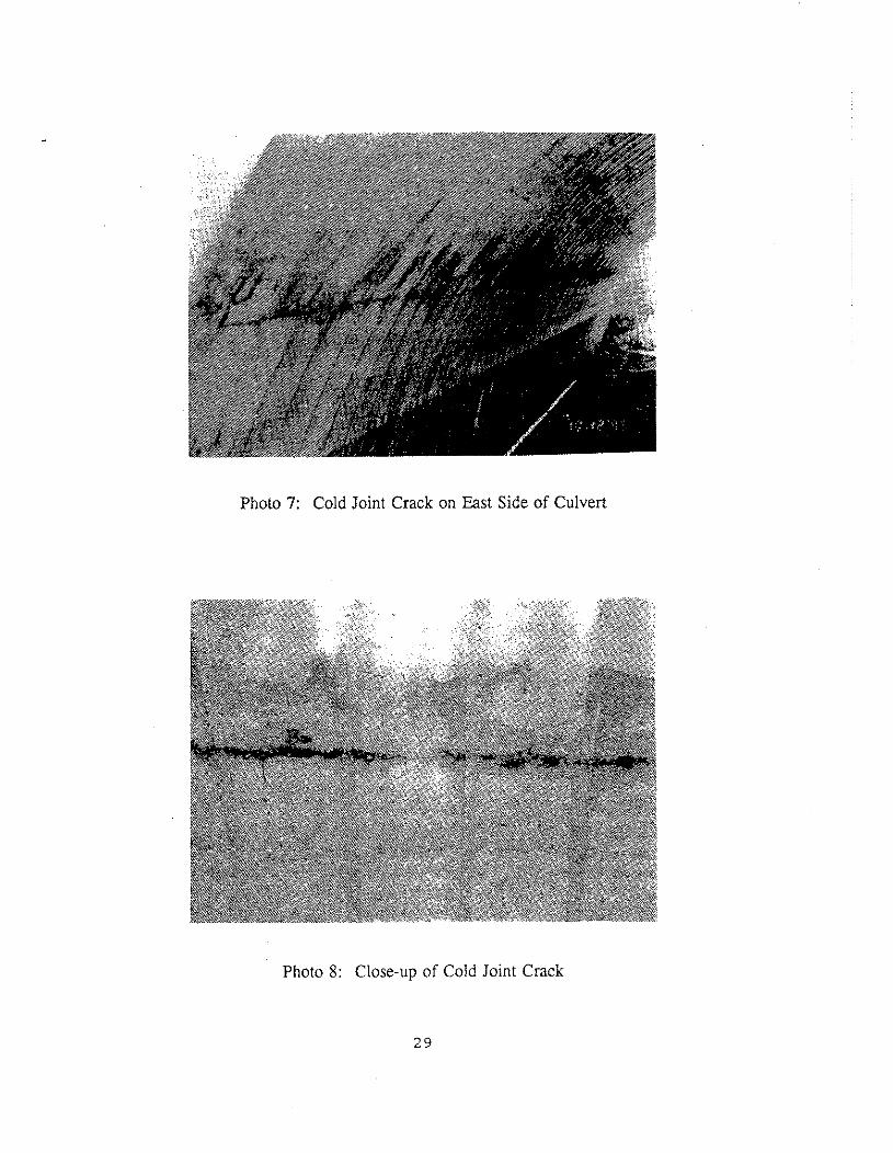
Photo 7: Cold Joint Crack on East Side of Culvert
Photo 8: Close-up of Cold Joint Crack
29
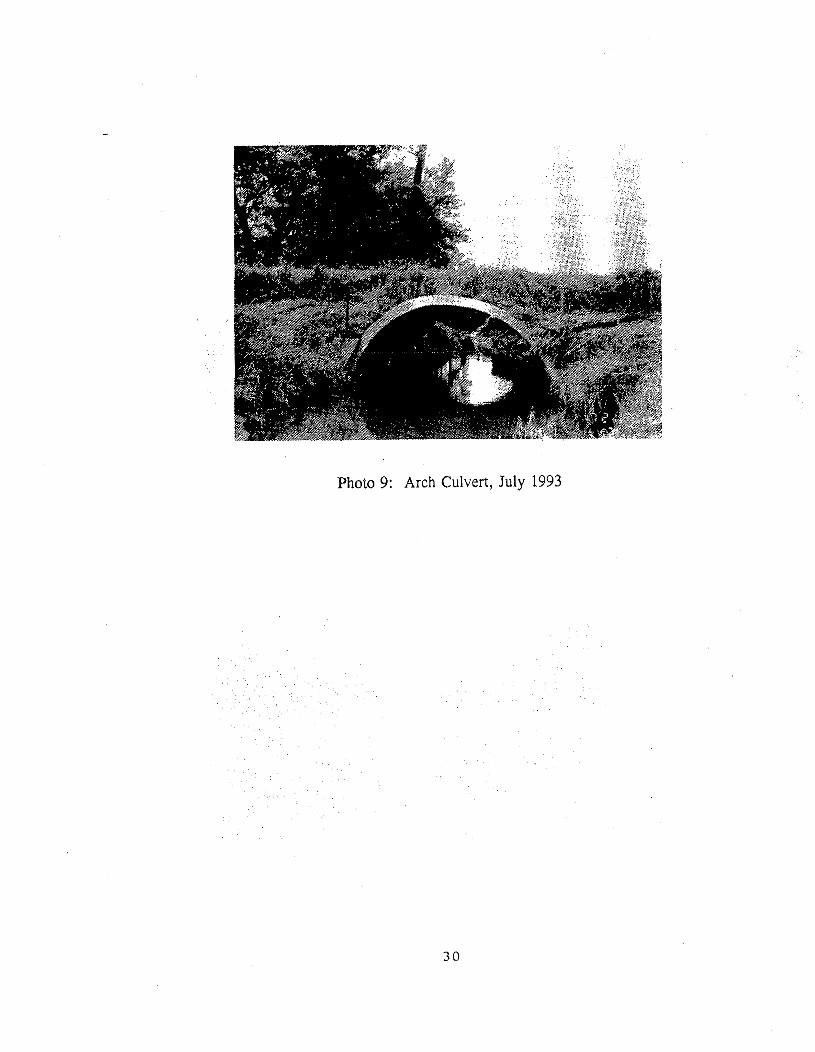
Photo 9: Arch Culvert, July 1993