air flow behaviour on different intake …eprints.uthm.edu.my/7316/1/1139.pdf · air flow behaviour...
TRANSCRIPT

VOL. X, NO. X, XXXXXXXX
ARPN Journal of Engineering and Applied Sciences
©2006-2015 Asian Research Publishing Network (ARPN). All rights reserved.
www.arpnjournals.com
ISSN 1819-6608
1
AIR FLOW BEHAVIOUR ON DIFFERENT INTAKE MANIFOLD
ANGLES FOR SMALL 4-STROKE PFI RETROFIT KIT SYSTEM
Mohd Faisal Hushim 1, Ahmad Jais Alimin 1, Mohd Azahari Razali 1, Akmal Nizam Mohammed 1, Azwan Sapit 1, Julio Cesar Mendez Carvajal 2
1 Automotive Research Group (ARG-UTHM), Centre for Energy and Industrial Environment Studies (CEIES),
Faculty of Mechanical & Manufacturing Engineering, Universiti Tun Hussein Onn Malaysia, 86400 Pt. Raja, Batu Pahat, Johor, Malaysia.
2 Department of Mechanical Engineering, North Carolina A&T State University,
Greensboro, NC. U.S.A. E-Mail: [email protected]
ABSTRACT Air flow behaviour plays an important role in order to provide better air fuel mixture inside the intake manifold for port fuel injection (PFI) system before it is drawn to the combustion chamber. This paper presents a computational fluid dynamics study that investigates the air flow behaviour inside a different intake manifold angles. This study is a continuation from the author’s previous studies that have been conducted by experiment and simulation study using a different simulation tool (GT-POWER). Six angles of intake manifold have been investigated using CFX simulation tool which are 30°, 60°, 90°, 120°, 150°, and 180°. From the study, results indicated 180° as the best option for intake manifold angle due to better air flow behaviour inside the intake manifold. This show an agreement to the previous submitted results that was done by using GT-POWER.
Keywords: Intake Manifold Angle PFI System Air Flow Behaviour Small 4-Stroke Engine INTRODUCTION
This paper is a continuation of the study that
investigates the effects of different intake manifold angle of a retrofitted port fuel injection (PFI) system to the small 4-stroke 125 cc engine performance. The authors have studied its effects by experiment and simulation using a different simulation tool (GT-POWER). Based on previous studies , high angle of intake manifold will provide better engine performance in terms of high brake torque (BT), brake power (BP), brake mean effective pressure (BMEP), and volumetric efficiency (VE) (Mohd Faisal Hushim, Ahmad Jais Alimin et al. 2012, Hushim, Alimin et al. 2013). Due to this, a continuation study was done in order to investigate the air flow behaviour inside the intake manifold with different angle.
Engine performance and exhaust out emissions
for an engine depends on several factors, and one of that is air fuel mixture behaviour. For a PFI system, air and fuel will mixed together inside the intake manifold before it is be drawn to the combustion chamber.
The PFI fuelling system is comprised of two major parts which are fuel injector and intake manifold. Fuel injector will inject a certain amount of fuel in the form of fuel mist based on fuel demand commanded by an electronic control unit (ECU) of the system. On the other hand, the intake manifold is a mechanical device that plays
an important role to provide good air fuel ratio (AFR) to the spark ignition (SI) engine. The main function of an intake manifold is to deliver as much air-fuel mixture to the combustion chamber as possible. There are several researchers (until now) that are working on either experimental or simulation study to investigate the effect of intake manifold to the performances and exhaust emissions of the internal combustion engine (ICE) (Yasar, Sahin et al. 2006, Al-Rousan and Al-Ajlouni 2008, Iida, Yoshikawa et al. 2009, Ceviz and AkIn 2010, Sulaiman, Murad et al. 2010, Bordjane, Chalet et al. 2011). Ceviz & AkIn (2010) studied the effect of variable length plenum on the performance characteristics of ICE. This is one of the most remarkable developments of intake manifold. From the study, the variation of plenum length causes an improvement on the engine performance characteristics especially in engine specific fuel consumption. Although it proves the positive improvement, however, the design is too complex and expensive to produce.

VOL. X, NO. X, XXXXXXXX
ARPN Journal of Engineering and Applied Sciences
©2006-2015 Asian Research Publishing Network (ARPN). All rights reserved.
www.arpnjournals.com
ISSN 1819-6608
2
Al-Rousan & Al-Ajlouni (2008) stated that homogenous mixture is important in order to optimize volumetric efficiency, improve fuel economy and reduce exhaust emission because this mixture is easy to evaporate, burn and consumed by the engine.
Sulaiman et al. (2010) performed an investigative study on the air flow characteristics in various designs of intake manifold by experiment test and numerical approach. The simulation study was done using computational fluid dynamics (CFD) software – Fluent and the results were validated by experiments approach using a commercial flow bench. Their studies are of interest for this study, because they used a slightly similar test engine characteristic, which are a single cylinder 4-stroke spark ignition engine with one valve each at the intake and exhaust ports. However, the engine’s capacity is 200 cc compared to the current authors research, with the selected engine being only 125 cc. Flow rate and flow coefficient of air entering the combustion chamber are two parameters that are of interest. From the studies, they reported that a different up to 20% in the mass flow rate can be recorded due to the variations in the geometry of intake manifold. The variations of intake manifold that were studied by experiment using flow bench are depicted in Figure-1 below.
Intake manifold is simple in design, but the processes occurring inside the manifold are too complex because the air flow is not steady and is pulsating. There are several restrictions in designing an intake manifold as documented by AutoWare (1999) and are listed below:
i. The
manifold runner must to be kept as short as possible to minimize fuel delivery lag.
ii. The air is hard to be sucked by the vacuum if the diameter of runner is too small in comparison to the combustion chamber.
iii. The wall of runner cannot be too rough and jagged that can cause friction to the air to move
down. These restrictions, severely limits the number of
manifold tuning. However, the function of intake manifold for PFI system is slightly different compared for carburetted system. For PFI system, the fuel injector is controlled electronically and only air flows inside the intake manifold, while the fuel is injected directly into the intake port.
Although the intake manifold for PFI system is
slightly different, those restrictions still need to be tackled successfully.
The first two challenges as listed above are the main factors needed to be
considered: runner size
(diameter) and length.
For the runner size, the smaller the
runner diameter, the faster the velocity of air flows through it for the same
air requirement.
Smaller size will offer better engine response and
Figure-1. The variation designs of intake manifold for experimental test using flow bench

VOL. X, NO. X, XXXXXXXX
ARPN Journal of Engineering and Applied Sciences
©2006-2015 Asian Research Publishing Network (ARPN). All rights reserved.
www.arpnjournals.com
ISSN 1819-6608
3
increased torque at low-revolutions-per-minute (RPM) by penalising the upper RPM performance. However a diameter size that is too large will result in poor lower-RPM performance and response. Shannak et al. (2005) studied the influence of air intake pipe with the focus only on engine exhaust emissions. They conducted an experimental investigation on a 4-cylinder 4-stroke gasoline engine using six air intake pipe diameters; 20, 25, 30, 35, 40, and 63 mm. The findings based on their studies are:
i. At small air intake pipe diameter – 20 mm, the hydrocarbon (HC) and carbon monoxide (CO) concentrations were relatively high at low engine speed – 1000 rpm.
ii. Both pollutants which are HC and CO were found to have a minimum concentrations at large diameter – 63 mm and at high engine speed – 4000 rpm.
iii. Carbon dioxide (CO2) and oxygen (O2) values remain relatively constant at a wide range of different operating conditions.
For the current study, the runner size was fixed based on original equipment manufacturing (OEM) size. Another parameter that gives impact in intake manifold is runner length. Runner length will vary due to intake manifold inclinations. Krishna, Bijucherian & Mallikarjuna (2010) studied the effect of intake manifold inclinations using particle image velocimetry (PIV). From their studies, a lot of information obtained is very useful in optimization of the geometry and orientation of intake manifold of the modern IC engine. They studied four different angles of inclinations which were 0, 30, 60, and 90° (on horizontal plane) and reported that, the highest angle of inclination produced the highest Turbulent Kinetic Energy (TKE).
CFX SIMULATION STUDY: STEADY AIR FLOW ANALYSIS
Air flow analysis inside the intake manifold was
performed using CFD software – Ansys CFX. The objective of this study was to understand the air flow behaviour and the effects on the flow inside the manifold with different angles to the engine performance as has been studied and presented by the authors previously.
All six intake manifolds that were studied
previously by using engine performance simulation study
(GT-POWER) were then simulated numerically in this study. The six intake manifolds that were investigated are 30°, 60°, 90°, 120°, 150°, and 180°. Figure-2 depicts the six simulated intake manifolds. Table-1 shows the labels for intake manifolds.
Figure-2. Variation designs (angle) of intake manifold for simulation study
Table-1: Intake manifold labels
For this study, the morphology of air was as
continuous fluid and during the simulation process, air density was assumed to be constant. The incompressible Navier-Stokes equations under the K-ε two-equation was chosen for the turbulence model. This model independently calculates turbulent viscosity and a length scale using two equations related to kinetic energy of the turbulence, k, and the rate of dissipation, ε. This k-ε turbulence model was chose for several reasons; the model has been widely used for a wide range of turbulent flow applications and has become almost a standard for this application (turbulent flow) due to its virtues in robustness, accuracy, and economy of computational efficiency.
Three boundaries were created for the inlet,
outlet, and wall. The boundary conditions for this study were set-up as stated in Table-2. This study was run under steady state simulation.
Table-2: Boundary conditions specification for the numerical simulation study
RESULTS AND DISCUSSION
Two result characteristics were presented here, which are; air pressure and velocity contour. The air pressure and velocity contours for six intake manifold models are depicted in Figure-3. The simulation was run under steady-state condition, same conditions as those
used in the authors’ previous studies; GT-POWER simulation and experimental investigation studies, in order to achieve comparable results.
From the figure, it depicts different pressure and
velocity contours for each design of intake manifold. For the velocity contour, it can be seen that, air inside
Intake Manifold Manifold A 180° Manifold B 150° Manifold C 120° Manifold D 90° Manifold E 60° Manifold F 30°
Boundary Conditions Parameters Conditions Inlet pressure 101.3 kPa Outlet pressure 0 Pa
Intake manifold wall No slip wall and smooth wall roughness
Air velocity 15 m/s Air temperature 300 K

VOL. X, NO. X, XXXXXXXX
ARPN Journal of Engineering and Applied Sciences
©2006-2015 Asian Research Publishing Network (ARPN). All rights reserved.
www.arpnjournals.com
ISSN 1819-6608
4
Manifold A which is a straight pipe flows with the highest homogeneity along the pipe. This homogeneity flow profile was due to no restriction to the air flow from the inlet to the outlet along the pipe.
Figures-3(b) – 3(f) depicts the velocity contours
when intake manifold angle are gradually decreased from 180° to 30°. The bending will affect the flow pattern and also pressure inside the pipe. Based on authors previous studies (Hushim, Alimin et al. 2013), there are only slight differences on the engine performance as simulated by GT-Power, however based on numerical study the differences between each intake manifold is obvious. From the figure it was found that air velocity reduces at certain area inside the pipe with the decreases of intake manifold angle, or in other words high angle of intake manifold will produced higher air velocity.
The velocity contour start to change when
bending was applied to the intake manifold. As can be seen, for the bending intake manifold with its specific angle, high velocity occurred near the inner bending wall while at the outer bending wall low air velocity was observed. This situation happened due to the travel distance of air along the pipe. It can be stated that, the bending side work as a shortcut distance for the air to travel inside the pipe. For the inner bending side, the air flow velocity will increase as air flow through this shorter distance. However, due to the longer distance air travelled, it results in lower air velocity. This situation was also reported by Tajul, Hadi & Roslan (2012). As the bending pipe increases, it reduces the air flow along the pipe, hence flow characteristics will change.
Air restriction can reduce power from the engine.
Air resistance must be avoided as best as possible. For this case, the bending of the pipe works as a resistance to the air flow. The straight intake manifold is the best manifold that can eliminate air resistance. This proves that the highest angle of intake manifold is the best angle that can produce better performance due to less air flow resistance in its.
The velocity contours in Figure-3 for each
designs depicts several different velocity regions inside the manifold. A greenish region as can been seen, starts to develop at the outer bending wall. And this region became larger and turned to darker colour as the angle of intake manifold decreases. This effect means that for this study, the air flow characteristics inside the intake manifold is directly affected by the bending angle of the pipe.
From the same figures, the greenish region also occurred near the inner wall after bending. The same situations like what have been happened at the outer bending wall were observed for this location. As the angle of intake manifold decreases, this greenish region became
larger and turned to darker colour. From these two locations; the outer bending wall and inner wall after bending, it was observed that the lowest velocity region occurred inside the Manifold F which is the lowest degree of bending. The lowest velocity region occurred at the area near the inner wall after bending.
For the pressure contour, pressure gradient was
observed along pipe for each design. The figure depicts that for Manifold A, the pressure contour at the inlet pipe is high before it starts to decline along the pipe. This situation happened due to the velocity of the air at the outlet is higher compared to the inlet.
Referring to the pressure contour figures, high
pressure region start to develop at the outer bend wall, and low pressure at the inner bend wall. As the angle of manifold decreases, the high pressure region increases and becomes larger. The highest pressure region was observed at the lowest air flow velocity region inside the pipe. It can be seen that, the lowest pressure region occurred at the bending area due to the highest air flow at this area.
Homogeneous charge is one of the key important
aspect in the PFI system. To gain a better performance, the air-fuel must be mixed homogeneously, so the vaporized fuel can be transported to the combustion chamber perfectly and then combusted effectively. Due to this, when referring to the pressure contour and outlet velocity for each manifold, it can be observed that, there is no major distinction in pressure gradient at the outer wall after bend for Manifold A and Manifold B. While for the outlet velocity, it was noticed that, high air velocity occurred at the center of pipe. High air flow at the center of pipe is important in promoting good air-fuel mixture, transporting the mixture homogeneously to the combustion chamber and at the same time reducing fuel film formation at the intake wall. The outer wall after bend is the area or location where the fuel injector was mounted. If high pressure occurred at this area, the injected fuel would not fully atomized and not reach perfectly to the center of air stream. Hence, it affects the mixture between air flow and the injected fuel where an incomplete mixture was produced, and as a consequence it will affect the engine performance. Due to this, Manifold C, D, E, and F can be disregarded.
For the PFI system, the fuel injector was mounted
on intake manifold, and the fuel will be injected inside the manifold into the air stream either directly to the intake valve face or to the manifold wall. There are three conceptual fuel film locations that can be thought to occupy for this type of fuelling system which are; a valve fuel film, a downstream port film and an upstream port film (Merola, Sementa et al. 2007, Scaringe 2007).
In order to achieve better engine performance and
reducing fuel film formation, the injected fuel must be mixed homogenously with air before it is drawn to the

VOL. X, NO. X, XXXXXXXX
ARPN Journal of Engineering and Applied Sciences
©2006-2015 Asian Research Publishing Network (ARPN). All rights reserved.
www.arpnjournals.com
ISSN 1819-6608
5
combustion chamber. Due to this, Manifold A seems to be best suited for transporting the fuel mixture into the combustion chamber and this has shown an agreement with the authors previous study based on GT-Power which produced the highest BT, BP, BMEP and VE.
Pressure Scale Pressure Contour Velocity Contour Velocity Scale
(a) Pressure contour and velocity contours for Manifold A (180°)
(b) Pressure contour and velocity contours for Manifold B (150°)
(c) Pressure contour and velocity contours for Manifold C (120°)
Figure-3. Pressure and velocity contours plots for all intake manifold models
Pressure Scale Pressure Contour Velocity Contour Velocity Scale
Outer wall after bend
Inner wall after bend
Area after bend
Area before bend
Flow direction Inlet
Outlet
Outer bend
Inner bend
VOL. X, NO. X, XXXXXXXX
ARPN Journal of Engineering and Applied Sciences
©2006-2015 Asian Research Publishing Network (ARPN). All rights reserved.
www.arpnjournals.com
ISSN 1819-6608
6
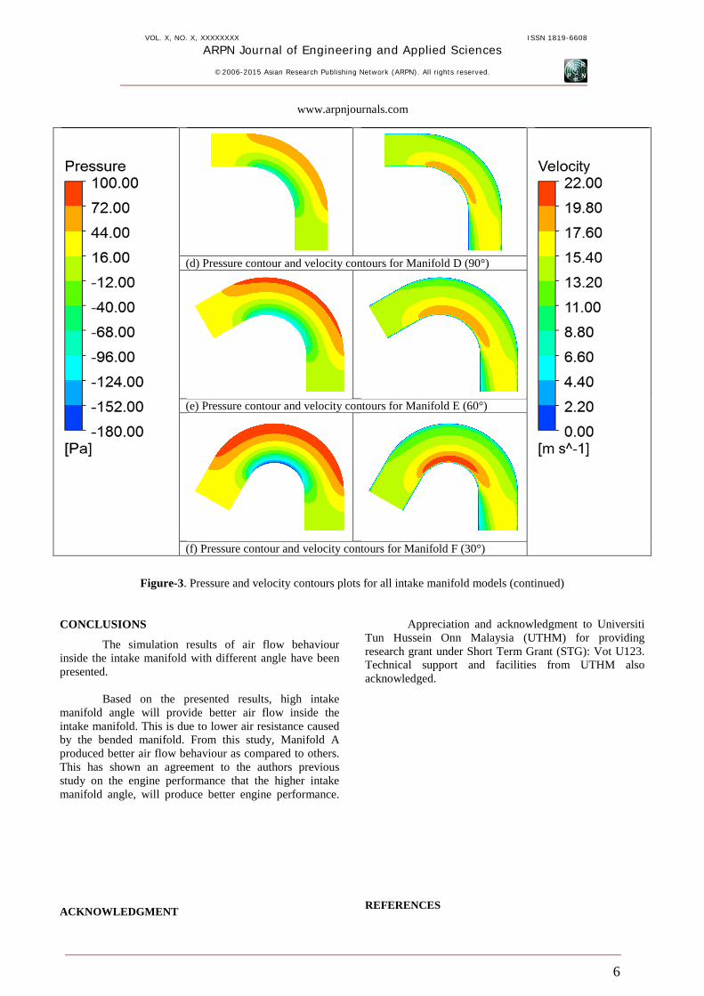
(d) Pressure contour and velocity contours for Manifold D (90°)
(e) Pressure contour and velocity contours for Manifold E (60°)
(f) Pressure contour and velocity contours for Manifold F (30°)
Figure-3. Pressure and velocity contours plots for all intake manifold models (continued)
CONCLUSIONS
The simulation results of air flow behaviour inside the intake manifold with different angle have been presented. Based on the presented results, high intake manifold angle will provide better air flow inside the intake manifold. This is due to lower air resistance caused by the bended manifold. From this study, Manifold A produced better air flow behaviour as compared to others. This has shown an agreement to the authors previous study on the engine performance that the higher intake manifold angle, will produce better engine performance.
ACKNOWLEDGMENT
Appreciation and acknowledgment to Universiti Tun Hussein Onn Malaysia (UTHM) for providing research grant under Short Term Grant (STG): Vot U123. Technical support and facilities from UTHM also acknowledged.
REFERENCES

VOL. X, NO. X, XXXXXXXX
ARPN Journal of Engineering and Applied Sciences
©2006-2015 Asian Research Publishing Network (ARPN). All rights reserved.
www.arpnjournals.com
ISSN 1819-6608
7
Al-Rousan, A. A. and M. Al-Ajlouni (2008). "Study on Improvement of Fuel Economy and Reduction Emission for a Gasoline Engines by Homogeneity Enhancement of the Charge." Australian Journal of Basic and Applied Sciences. AutoWare. (1999). "Induction Basics more than just performance engine parts." Retrieved 01 June, 2011, from http://www.auto-ware.com/combust_bytes/eng_sci2.htm. Bordjane, M., D. Chalet, M. Abidat and P. Chessé (2011). "Inertial effects on fluid flow through manifolds of internal combustion engines." Proceedings of the Institution of Mechanical Engineers, Part A: Journal of Power and Energy 225(6): 734-747. Ceviz, M. A. and M. AkIn (2010). "Design of a new SI engine intake manifold with variable length plenum." Energy Conversion and Management 51(11): 2239-2244. Hushim, M. F., A. J. Alimin, H. Selamat and M. T. Muslim (2013). "GT-Suite Investigation on the Effects of Intake Manifold Angle to the Performance of a 125 cc Engine Retrofitted with PFI System." Academic Journal of Science 2(2): 65 - 70. Iida, M., K. Yoshikawa, H. Tanaka, G. Wang and C. Arcoumanis (2009). "Fuel Film Behavior Analysis Using Simulated Intake Port." Yamaha Motor Technical Review. Krishna, B. M., A. Bijucherian and J. M. Mallikarjuna (2010). "Effect of Intake Manifold Inclination on Intake Valve Flow Characteristics of a Single Cylinder Engine using Particle Image Velocimetry." International Journal of Engineering and Applied Sciences.
Merola, S., P. Sementa, C. Tornatore and B. Vaglieco (2007). "Effect of fuel film deposition on combustion process in PFI SI engine." Journal of KONES 14: 395-402. Mohd Faisal Hushim, Ahmad Jais Alimin and M. F. Mansor (2012). "Effect of Intake Manifold Angle of Port-Fuel Injection Retrofit-Kit to the Performances of an S.I. Engine." Applied Mechanics and Materials (Volume 165) Trends in Automotive Research: 31-37. Scaringe, R. J. (2007). Effect of directed port air flow on liquid fuel transport in a port fuel injected spark ignition engine, Massachusetts Institute of Technology. Shannak, B., R. Damseh and M. Alhusein (2005). "Influence of air intake pipe on engine exhaust emission." Forschung im Ingenieurwesen 70(2): 128-132. Sulaiman, S., S. Murad, I. Ibrahim and Z. Abdul Karim (2010). "Study Of Flow In Air-Intake System For A Single-Cylinder Go-Kart Engine." International Journal of Automotive and Mechanical Engineering (IJAME) 1: 91-104. Tajul, L., H. Hadi and M. Roslan (2012). "Vibration Analysis of Blocked Circular Pipe Flow." Applied Mechanics and Materials 165: 197-201. Yasar, A., B. Sahin, H. Akilli and K. Aydin (2006). "Effect of inlet port on the flow in the cylinder of an internal combustion engine." Proceedings of the Institution of Mechanical Engineers, Part C: Journal of Mechanical Engineering Science 220(1): 73-82.