air conditioning technical data€¢ outdoor unit • rzq-c 1 2 • split - sky air • rzq-c 1...
TRANSCRIPT
Air Conditioning
Technical DataPair, Twin, Triple, double twin
EEDEN15-100
RZQ-C

• Split - Sky Air • RZQ-C 1
• Outdoor Unit • RZQ-C
TABLE OF CONTENTSRZQ-C
1 Features . . . . . . . . . . . . . . . . . . . . . . . . . . . . . . . . . . . . . . . . . . . . . . . . . . . . . . . . . . . . . 2
2 Specifications . . . . . . . . . . . . . . . . . . . . . . . . . . . . . . . . . . . . . . . . . . . . . . . . . . . . . . . 3
Capacity and Power input . . . . . . . . . . . . . . . . . . . . . . . . . . . . . . . . . . . . . . . . . . . . 3
Technical Specifications . . . . . . . . . . . . . . . . . . . . . . . . . . . . . . . . . . . . . . . . . . . . . 3
Electrical Specifications . . . . . . . . . . . . . . . . . . . . . . . . . . . . . . . . . . . . . . . . . . . . . . 5
3 Electrical data . . . . . . . . . . . . . . . . . . . . . . . . . . . . . . . . . . . . . . . . . . . . . . . . . . . . . . . 6
4 Options . . . . . . . . . . . . . . . . . . . . . . . . . . . . . . . . . . . . . . . . . . . . . . . . . . . . . . . . . . . . . 10
5 Combination table . . . . . . . . . . . . . . . . . . . . . . . . . . . . . . . . . . . . . . . . . . . . . . . . . 11
6 Capacity tables . . . . . . . . . . . . . . . . . . . . . . . . . . . . . . . . . . . . . . . . . . . . . . . . . . . . 12
Cooling Capacity Tables . . . . . . . . . . . . . . . . . . . . . . . . . . . . . . . . . . . . . . . . . . . . 12
Heating Capacity Tables . . . . . . . . . . . . . . . . . . . . . . . . . . . . . . . . . . . . . . . . . . . . 16
Cooling/Heating Capacity Tables . . . . . . . . . . . . . . . . . . . . . . . . . . . . . . . . . . . 20
7 Dimensional drawings . . . . . . . . . . . . . . . . . . . . . . . . . . . . . . . . . . . . . . . . . . . . 21
Dimensional Drawings . . . . . . . . . . . . . . . . . . . . . . . . . . . . . . . . . . . . . . . . . . . . . . 21
Dimensional Drawings with Accessories . . . . . . . . . . . . . . . . . . . . . . . . . . . . 22
8 Centre of gravity . . . . . . . . . . . . . . . . . . . . . . . . . . . . . . . . . . . . . . . . . . . . . . . . . . . 23
9 Piping diagrams . . . . . . . . . . . . . . . . . . . . . . . . . . . . . . . . . . . . . . . . . . . . . . . . . . . 24
Piping Diagrams . . . . . . . . . . . . . . . . . . . . . . . . . . . . . . . . . . . . . . . . . . . . . . . . . . . . 24
Piping Diagram Twin Application . . . . . . . . . . . . . . . . . . . . . . . . . . . . . . . . . . . . 25
Piping Diagram Triple Application . . . . . . . . . . . . . . . . . . . . . . . . . . . . . . . . . . . 26
Piping Diagram Double Twin Application . . . . . . . . . . . . . . . . . . . . . . . . . . . 27
10 Wiring diagrams . . . . . . . . . . . . . . . . . . . . . . . . . . . . . . . . . . . . . . . . . . . . . . . . . . . 28
Wiring Diagrams - Three Phase . . . . . . . . . . . . . . . . . . . . . . . . . . . . . . . . . . . . 28
11 Sound data . . . . . . . . . . . . . . . . . . . . . . . . . . . . . . . . . . . . . . . . . . . . . . . . . . . . . . . . . 29
Sound Power Spectrum . . . . . . . . . . . . . . . . . . . . . . . . . . . . . . . . . . . . . . . . . . . . . 29
Sound Pressure Spectrum - Cooling . . . . . . . . . . . . . . . . . . . . . . . . . . . . . . . . 30
Sound Pressure Spectrum - Heating . . . . . . . . . . . . . . . . . . . . . . . . . . . . . . . . 31
12 Installation . . . . . . . . . . . . . . . . . . . . . . . . . . . . . . . . . . . . . . . . . . . . . . . . . . . . . . . . . . 32
Installation Method . . . . . . . . . . . . . . . . . . . . . . . . . . . . . . . . . . . . . . . . . . . . . . . . . . 32
Fixation and Foundation of Units . . . . . . . . . . . . . . . . . . . . . . . . . . . . . . . . . . . . 33
13 Operation range . . . . . . . . . . . . . . . . . . . . . . . . . . . . . . . . . . . . . . . . . . . . . . . . . . . 34

• Outdoor Unit • RZQ-C
1
2
1 Features
door Uni it - Sk -C r, Twin,
Out Spl RZQ Pai Packaged system for commercial applications• Re-use of existing R-22 or R-407C technology
• Guarantees operation in heating mode down to -15°C
• Standard night quiet mode
• Maximum piping length up to 100m
• Maximum installation height difference up to 30m
Inverter Auto cooling-heating
changeover
• Split - Sky Air • RZQ-C
3
2
• Outdoor Unit • RZQ-C
2 Specifications
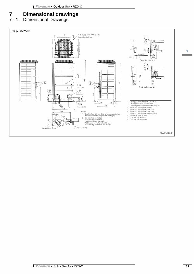
Notes
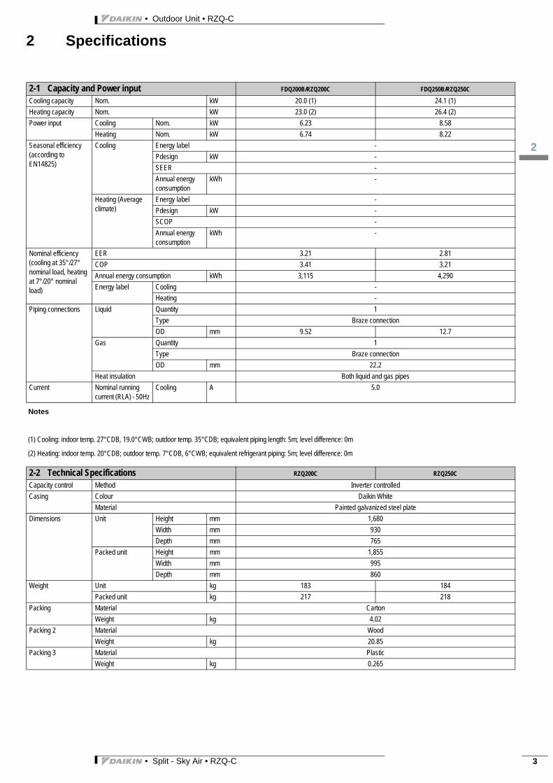
(1) Cooling: indoor temp. 27°CDB, 19.0°CWB; outdoor temp. 35°CDB; equivalent piping length: 5m; level difference: 0m
(2) Heating: indoor temp. 20°CDB; outdoor temp. 7°CDB, 6°CWB; equivalent refrigerant piping: 5m; level difference: 0m
2-1 Capacity and Power input FDQ200B/RZQ200C FDQ250B/RZQ250C
Cooling capacity Nom. kW 20.0 (1) 24.1 (1)
Heating capacity Nom. kW 23.0 (2) 26.4 (2)
Power input Cooling Nom. kW 6.23 8.58
Heating Nom. kW 6.74 8.22
Seasonal efficiency (according to EN14825)
Cooling Energy label -
Pdesign kW -
SEER -
Annual energy consumption
kWh -
Heating (Average climate)
Energy label -
Pdesign kW -
SCOP -
Annual energy consumption
kWh -
Nominal efficiency (cooling at 35°/27° nominal load, heating at 7°/20° nominal load)
EER 3.21 2.81
COP 3.41 3.21
Annual energy consumption kWh 3,115 4,290
Energy label Cooling -
Heating -
Piping connections Liquid Quantity 1
Type Braze connection
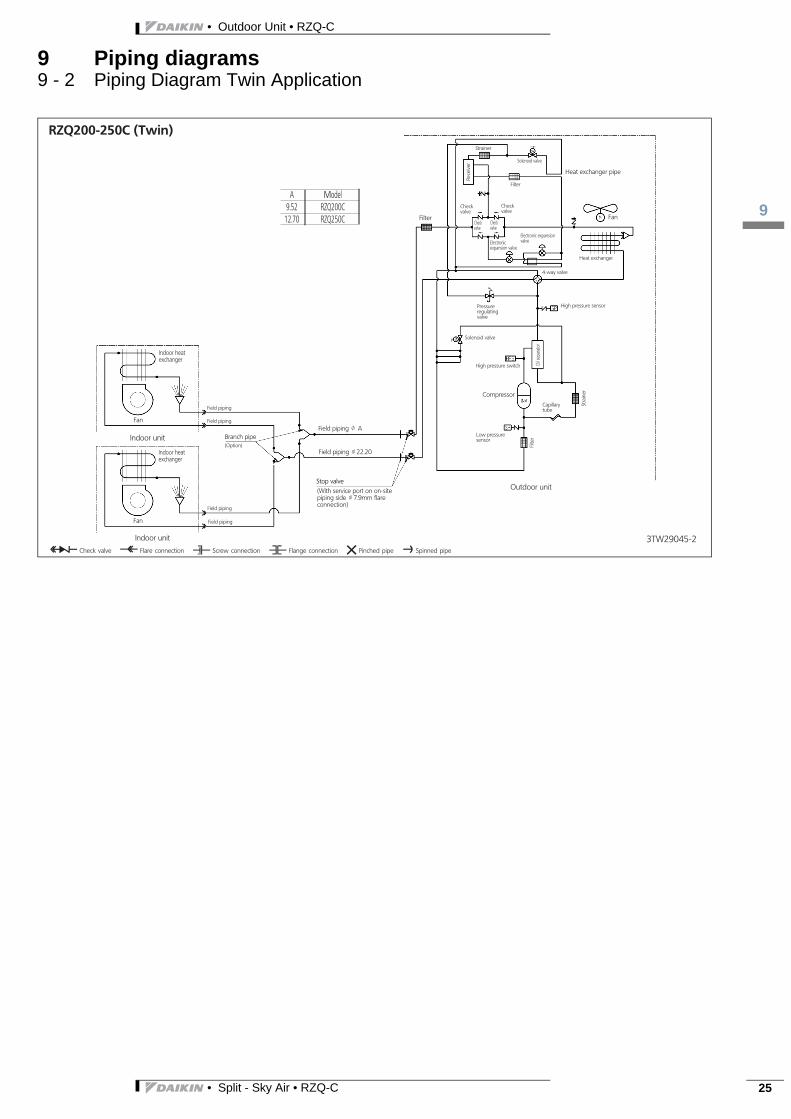
OD mm 9.52 12.7
Gas Quantity 1
Type Braze connection
OD mm 22.2
Heat insulation Both liquid and gas pipes
Current Nominal running current (RLA) - 50Hz
Cooling A 5.0
2-2 Technical Specifications RZQ200C RZQ250C
Capacity control Method Inverter controlled
Casing Colour Daikin White
Material Painted galvanized steel plate
Dimensions Unit Height mm 1,680
Width mm 930
Depth mm 765
Packed unit Height mm 1,855
Width mm 995
Depth mm 860
Weight Unit kg 183 184
Packed unit kg 217 218
Packing Material Carton
Weight kg 4.02
Packing 2 Material Wood
Weight kg 20.85
Packing 3 Material Plastic
Weight kg 0.265
• Split - Sky Air • RZQ-C 3
• Outdoor Unit • RZQ-C
2
4
2 Specifications
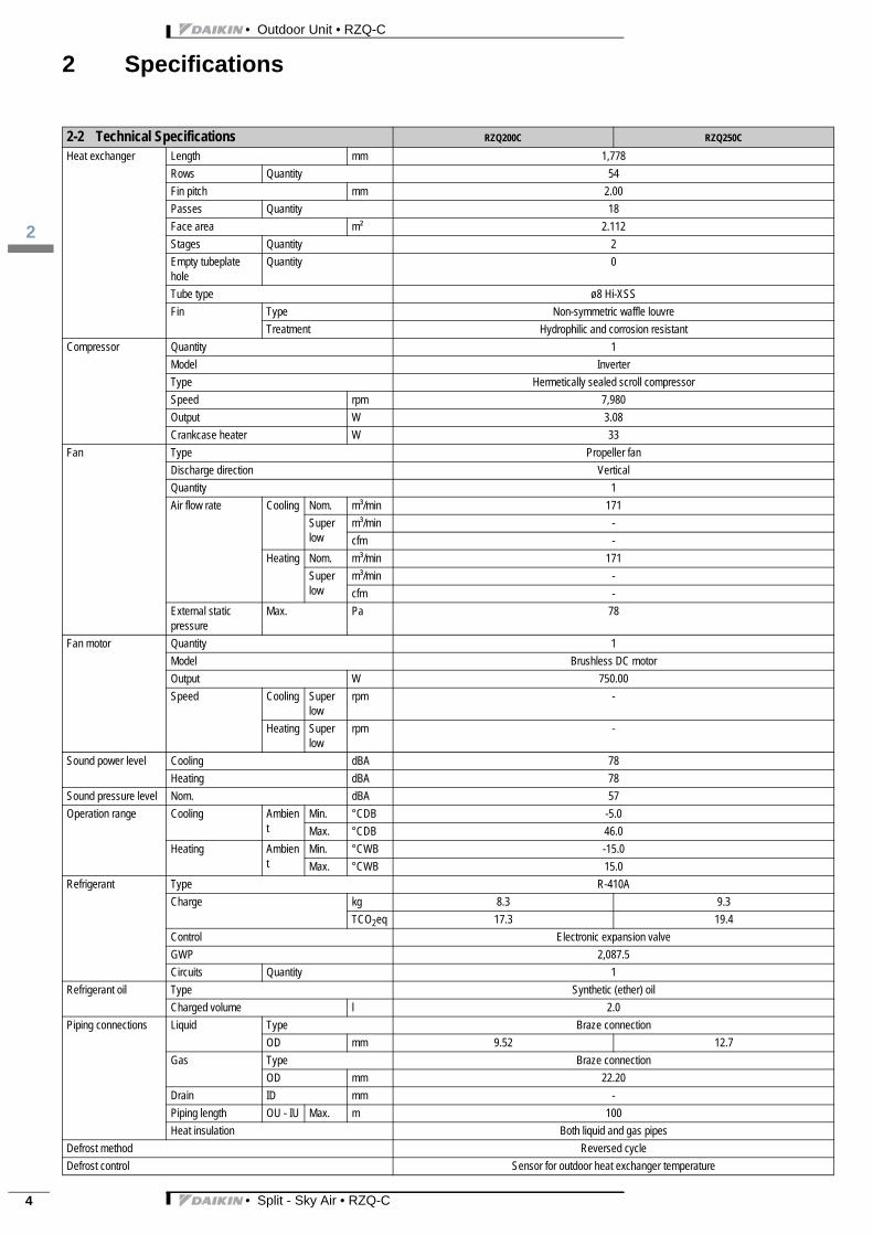
Heat exchanger Length mm 1,778
Rows Quantity 54
Fin pitch mm 2.00
Passes Quantity 18
Face area m² 2.112
Stages Quantity 2
Empty tubeplate hole
Quantity 0
Tube type ø8 Hi-XSS
Fin Type Non-symmetric waffle louvre
Treatment Hydrophilic and corrosion resistant
Compressor Quantity 1
Model Inverter
Type Hermetically sealed scroll compressor
Speed rpm 7,980
Output W 3.08
Crankcase heater W 33
Fan Type Propeller fan
Discharge direction Vertical
Quantity 1
Air flow rate Cooling Nom. m³/min 171
Super low
m³/min -
cfm -
Heating Nom. m³/min 171
Super low
m³/min -
cfm -
External static pressure
Max. Pa 78
Fan motor Quantity 1
Model Brushless DC motor
Output W 750.00
Speed Cooling Super low
rpm -
Heating Super low
rpm -
Sound power level Cooling dBA 78
Heating dBA 78
Sound pressure level Nom. dBA 57
Operation range Cooling Ambient
Min. °CDB -5.0
Max. °CDB 46.0
Heating Ambient
Min. °CWB -15.0
Max. °CWB 15.0
Refrigerant Type R-410A
Charge kg 8.3 9.3
TCO2eq 17.3 19.4
Control Electronic expansion valve
GWP 2,087.5
Circuits Quantity 1
Refrigerant oil Type Synthetic (ether) oil
Charged volume l 2.0
Piping connections Liquid Type Braze connection
OD mm 9.52 12.7
Gas Type Braze connection
OD mm 22.20
Drain ID mm -
Piping length OU - IU Max. m 100
Heat insulation Both liquid and gas pipes
Defrost method Reversed cycle
Defrost control Sensor for outdoor heat exchanger temperature
2-2 Technical Specifications RZQ200C RZQ250C
• Split - Sky Air • RZQ-C

3
2
• Outdoor Unit • RZQ-C
2 Specifications
Notes
Sound power level is an absolute value that a sound source generates.
Sound pressure level is a relative value, depending on the distance and acoustic environment. For more details, please refer to the sound level drawings.
Sound values are measured in a semi-anechoic room.
Power supply to the FDQ indoor unit is separate
See separate drawing for electrical data
Contains fluorinated greenhouse gases
Safety devices Item 01 High pressure switch
02 Fan driver overload protector
03 Overcurrent relay
04 Inverter overload protector
05 PC board fuse
2-3 Electrical Specifications RZQ200C RZQ250C
Power supply Name Y1
Phase 3N~
Frequency Hz 50
Voltage V 380-415
Voltage range Min. % -10
Max. % 10
Current Zmax List No requirements
A Recommended fuses
25
Current - 50Hz Maximum fuse amps (MFA) A 20
Current - 60Hz Maximum fuse amps (MFA) A -
Wiring connections For power supply Quantity 5
Remark Earth wire included
For connection with indoor
Quantity 4
Remark Earth wire included
Power supply intake Outdoor unit only
2-2 Technical Specifications RZQ200C RZQ250C
• Split - Sky Air • RZQ-C 5
• Outdoor Unit • RZQ-C
3
6
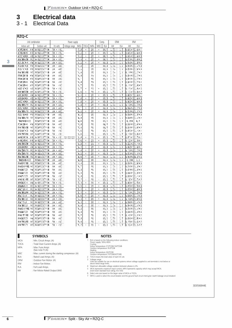
3 Electrical data3 - 1 Electrical Data
• Split - Sky Air • RZQ-C

3
3
• Outdoor Unit • RZQ-C
3 Electrical data3 - 1 Electrical Data
RZQ C
1 2 3 MCA MFA RHz RLA kW FLA kW FLA
OFMIFMFLAkWRHz
COMPRLA
MCAMFA
1
234
COMP OFM IFM
Voltage rangeVoltageHz
OutdoorIndoor
Unit combination restrictions Power supply
Symbols
Minimum Circuit Ampere (A)Maximum Fuse Ampere (A)Rated load amps [A]
Outdoor fan motorIndoor fan motorFull Load Ampere (A)Fan motor rated output [kW]
Notes
The RLA is based on the following conditions.Indoor temperature 27°C DB / 19°CWBOutdoor temperature 35°C DBSelect the wire size according to the MCA.
Use a circuit breaker instead of a fuse.
Rated operating frequency [Hz]
The maximum allowable voltage that is unbalanced between phases is 2%.
Compressor
3D094863B
RZQ200C
1 2 3 MCA MFA RHz RLA kW FLA kW FLA
OFMIFMFLAkWRHz
COMP
MCAMFARLA
234
1
COMP OFM IFM
Voltage rangeVoltageHz
OutdoorIndoor
Unit combination restrictions Power supply
Symbols
Minimum Circuit Ampere (A)Maximum Fuse Ampere (A)Rated load amps [A]
Outdoor fan motorIndoor fan motorFull Load Ampere (A)Fan motor rated output [kW]
Notes
The RLA is based on the following conditions.Indoor temperature 27°C DB / 19°CWBOutdoor temperature 35°C DBSelect the wire size according to the MCA.
Use a circuit breaker instead of a fuse.
Rated operating frequency [Hz]
The maximum allowable voltage that is unbalanced between phases is 2%.
Compressor
3D094863B
• Split - Sky Air • RZQ-C 7
• Outdoor Unit • RZQ-C
3
8
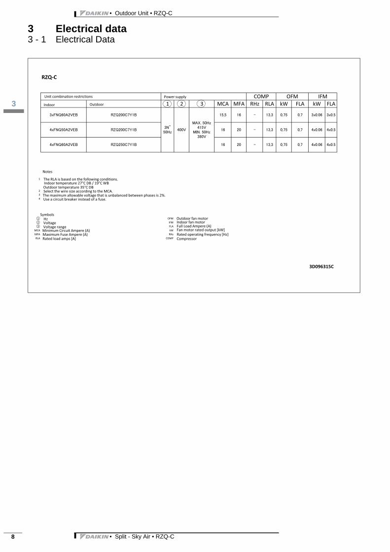
3 Electrical data3 - 1 Electrical Data
RZQ C
1 2 3 MCA MFA RHz RLA kW FLA kW FLA
OFMIFMFLAkWRHz
COMP
MCAMFARLA
234
1
COMP OFM IFM
Voltage rangeVoltageHz
OutdoorIndoor
Unit combination restrictions Power supply
Symbols
Minimum Circuit Ampere (A)Maximum Fuse Ampere (A)Rated load amps [A]
Outdoor fan motorIndoor fan motorFull Load Ampere (A)Fan motor rated output [kW]
Notes
The RLA is based on the following conditions.Indoor temperature 27°C DB / 19°CWBOutdoor temperature 35°C DBSelect the wire size according to the MCA.
Use a circuit breaker instead of a fuse.
Rated operating frequency [Hz]
The maximum allowable voltage that is unbalanced between phases is 2%.
Compressor
3D096315C
• Split - Sky Air • RZQ-C
3
3
• Outdoor Unit • RZQ-C
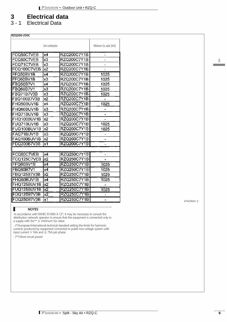
3 Electrical data3 - 1 Electrical Data
• Split - Sky Air • RZQ-C 9

• Outdoor Unit • RZQ-C
4
10
4 Options4 - 1 Options
• Split - Sky Air • RZQ-C

3
5
• Outdoor Unit • RZQ-C
5 Combination table5 - 1 Combination Table
RZQ C
Possible combinations and standard capacities for twin, triple and double twin operation
Twin Triple Double twin
100 100(KHRQ22M20TA)
60 60 6071 71 71(KHRQ250H)
50 50 50 50(3x KHRQ22M20TA)
125 125(KHRQ22M20TA)
60 60 60 60(3x KHRQ22M20TA)
Notes1. Possible indoor units
FCQG50 125FCQHG50 125FCQ50 125FFQ50,60FHQ50 125FBQ50 125FAQ71,100FUQ71 125FDQ125FDXS50 60FNQ50 60
2. The capacities in the table are combined capacities (multiple units operating simultaneously) and not individual indoor unit capacities.3. Do not combine indoor units of different types within the same installation.4. The refnet kits required to install the various combinations are mentioned between brackets.
Indoor unit combinationsSimultaneous operation
Outdoor units
RZQ200C7Y1B
RZQ250C7Y1B
OUT
IN IN
OUT
IN ININ
OUT
IN IN IN IN
3TW29049 2B
• Split - Sky Air • RZQ-C 11

• Outdoor Unit • RZQ-C
6
12
6 Capacity tables6 - 1 Cooling Capacity Tables
• Split - Sky Air • RZQ-C
3
6
• Outdoor Unit • RZQ-C
6 Capacity tables6 - 1 Cooling Capacity Tables
• Split - Sky Air • RZQ-C 13
• Outdoor Unit • RZQ-C
6
14
6 Capacity tables6 - 1 Cooling Capacity Tables
• Split - Sky Air • RZQ-C
3
6
• Outdoor Unit • RZQ-C
6 Capacity tables6 - 1 Cooling Capacity Tables
• Split - Sky Air • RZQ-C 15

• Outdoor Unit • RZQ-C
6
16
6 Capacity tables6 - 2 Heating Capacity Tables
• Split - Sky Air • RZQ-C

3
6
• Outdoor Unit • RZQ-C
6 Capacity tables6 - 2 Heating Capacity Tables
• Split - Sky Air • RZQ-C 17

• Outdoor Unit • RZQ-C
6
18
6 Capacity tables6 - 2 Heating Capacity Tables
• Split - Sky Air • RZQ-C
3
6
• Outdoor Unit • RZQ-C
6 Capacity tables6 - 2 Heating Capacity Tables
• Split - Sky Air • RZQ-C 19
• Outdoor Unit • RZQ-C
6
20
6 Capacity tables6 - 3 Cooling/Heating Capacity Tables
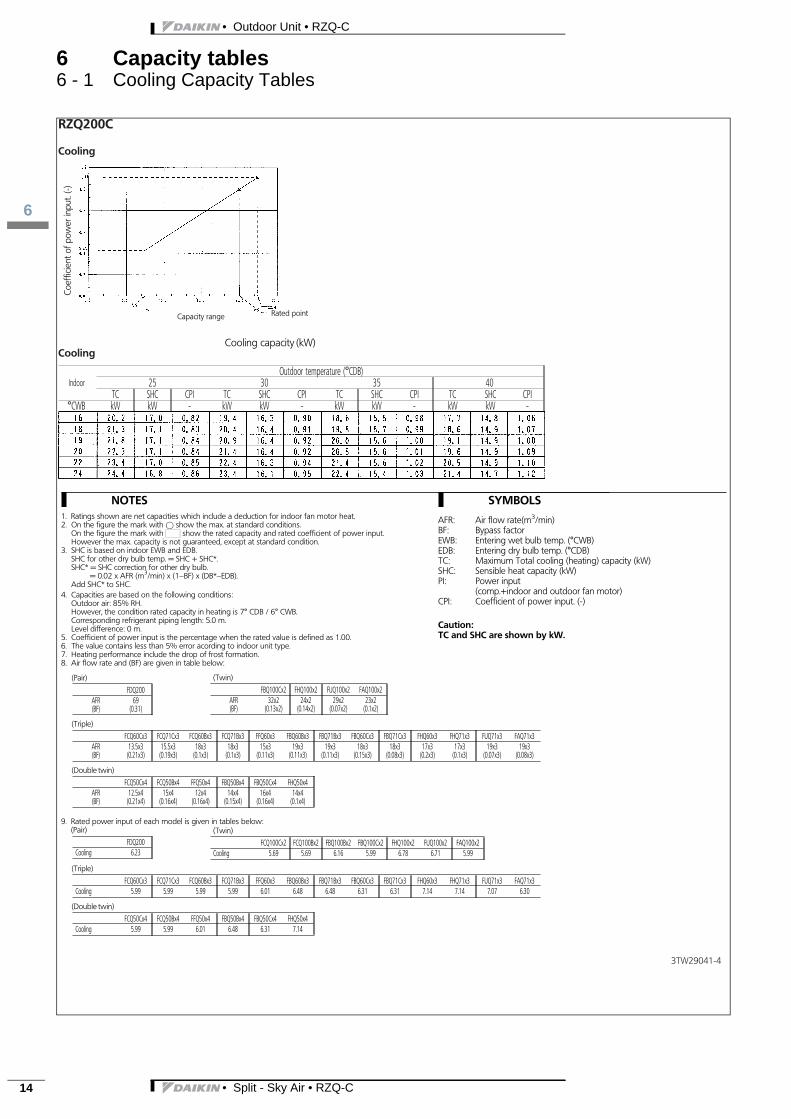
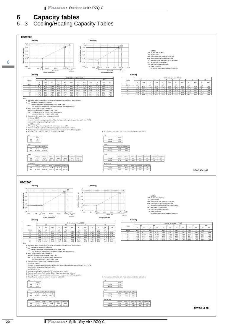
RZQ200CCooling Heating
SymbolsAFR: Air flow rate [m³/min]BF: Bypass factor
EWB: Entering wet bulb temperature (°C WB)EDB: Entering dry bulb temperature (°C DB)TC: Maximum total cooling/heating capacity [kW]
SHC: Sensible heat capacity [kW]CPI: Coefficient of the power inputPI: Power input [kW]
compressor + indoor and outdoor fan motors
Cooling Heating
Notes1. The ratings shown are net capacities which include a deduction for indoor fan motor heat.2. = Maximum at standard conditions
= Rated capacity and rated coefficient of the power inputThe maximum capacity is not guaranteed except at standard conditions.
3. SHC is based on indoor units EWB & EDB.SHC for other dry bulb temperatures = SHC + SHC*SHC* = SHC correction for other dry bulb temperatures
= 0.02 x AFR (m³/min) x (1 BF) x (DB* EDB)4. The capacities are based on the following conditions:
Outdoor air: 85% RHHowever, the outdoor ambient condition of the rated capacity during heating operation is 7°C DB / 6°C WB.Corresponding refrigerant piping length: 5.0 mLevel difference: 0m
5. CPI is a percentage value compared to the rated value which is 1.00.6. The error rate for this value is less than 5% and depends on the indoor unit type.7. The heating performance takes into account the drop that occurs during defrost operation.8. The air flow rate and bypass factor are mentioned in the table. 9. The rated power input for each model is mentioned in the table below.
Pair PairFDQ200 FDQ200
Cooling 6,23
Heating 6,74
Twin TwinFBQ100C X 2 FBQ100D X 2 FBQ100C X 2 FBQ100D X 2
Cooling 5,99 5,99
Heating 5,72 5,72
Triple TripleFFQ60 X 3 FBQ60C X 3 FBQ71C X 3 FBQ60D X 3 FBQ71D X 3 FDXS60F X 3 FNQ60A X 3 FFQ60 X 3 FBQ60C X 3 FBQ71C X 3 FBQ60D X 3 FBQ71D X 3 FDXS60F X 3 FNQ60A X 3
Cooling 6,01 6,31 6,31 6,31 6,31 6,93 6,93
Heating 6,54 6,05 6,05 6,05 6,05 6,62 6,62
Double twin Double twinFFQ50 X 4 FBQ50C X 4 FBQ50D X 4 FDXS50F9 X 4 FNQ50A X 4 FFQ50 X 4 FBQ50C X 4 FBQ50D X 4 FDXS50F9 X 4 FNQ50A X 4
Cooling 6,01 6,31 6,31 6,09 6,09
Heating 6,54 6,05 6,05 5,90 5,90AFR(BF)
12 x 4(0.16 x 4)
16 x 4(0.16 x 4)
15 x 4(0.13 x 4)
16 x 4(0.11 x 4)
16 x 4(0.11 x 4)
18 x 3(0.13 x 3)
16 x 3(0.12 x 3)
16 x 3(0.12 x 3)
AFR(BF)
15 x 3(0.11 x 3)
18 x 3(0.15 x 3)
18 x 3(0.08 x 3)
18 x 3(0.15 x 3)
AFR(BF)
32 x 2(0.13 x 2)
29 x 2(0.03 x 2)
AFR(BF)
69(0.31)
TC CPI TC CPI TC CPI TC CPI TC CPI TC CPI
WB kW kW kW kW kW kW16 10,8 0,83 12,2 0,87 13,9 0,91 15,5 0,96 23,3 0,97 25,4 1,0118 10,8 0,84 12,2 0,88 13,8 0,93 15,4 0,97 23,2 0,98 25,3 1,0320 10,7 0,85 12,1 0,90 13,7 0,94 15,3 0,99 23,0 1,00 25,1 1,0422 10,6 0,87 12,0 0,91 13,6 0,96 15,2 1,01 22,8 1,02 24,9 1,0624 10,5 0,88 11,9 0,93 13,5 0,98 15,1 1,02 22,7 1,03 24,7 1,08
6 1015 10 5 0Co
efficient
ofthepo
wer
inpu
t
Coefficient
ofthepo
wer
inpu
t
Cooling capacity [kW] Heating capacity [kW]Capacity range Rated point
Capacity rangeRated point
IndoorTC SHC CPI TC SHC CPI TC SHC CPI TC SHC CPI
WB kW kW kW kW kW kW kW kW16 20,2 17,0 0,82 19,4 16,3 0,90 18,6 15,5 0,98 17,7 14,8 1,0618 21,3 17,1 0,83 20,4 16,4 0,91 19,5 15,7 0,99 18,6 14,9 1,0719 21,8 17,1 0,84 20,9 16,4 0,92 20,0 15,6 1,00 19,1 14,9 1,0820 22,3 17,1 0,84 21,4 16,4 0,92 20,5 15,6 1,01 19,6 14,9 1,0922 23,4 17,0 0,85 22,4 16,3 0,94 21,4 15,6 1,02 20,5 14,9 1,1024 24,4 16,8 0,86 23,4 16,1 0,95 22,4 15,4 1,03 21,4 14,7 1,12
25 30 35 40Indoor
Outdoor temperature [°C DB] Outdoor temperature [°C WB]
3TW29041 4B
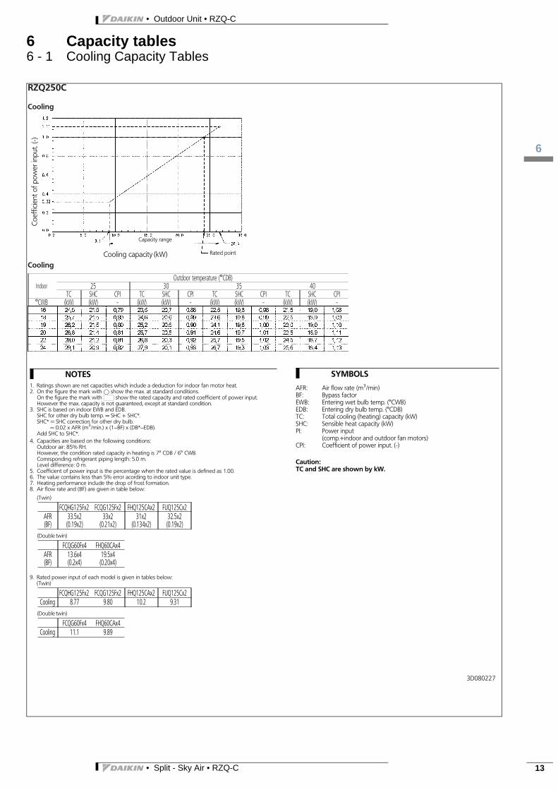
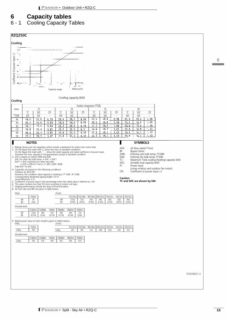
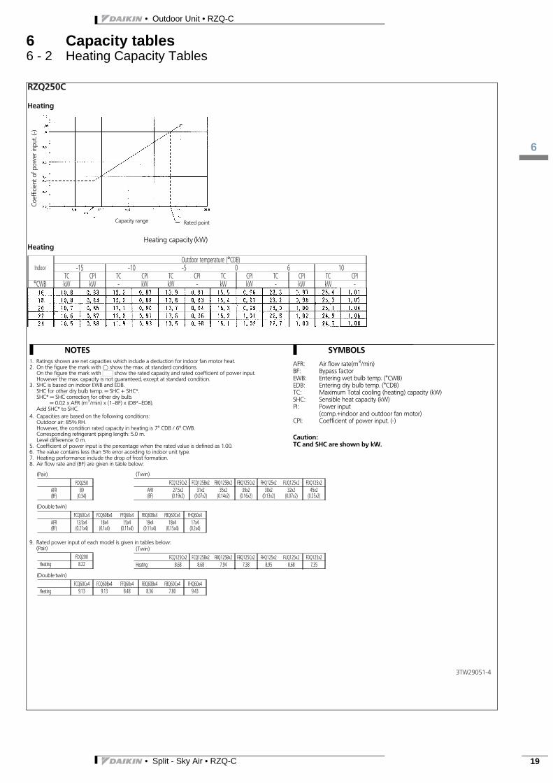
RZQ250CCooling Heating
SymbolsAFR: Air flow rate [m³/min]BF: Bypass factor
EWB: Entering wet bulb temperature (°C WB)EDB: Entering dry bulb temperature (°C DB)TC: Maximum total cooling/heating capacity [kW]
SHC: Sensible heat capacity [kW]CPI: Coefficient of the power inputPI: Power input [kW]
compressor + indoor and outdoor fan motors
Cooling Heating
Notes1. The ratings shown are net capacities which include a deduction for indoor fan motor heat.2. = Maximum at standard conditions
= Rated capacity and rated coefficient of the power inputThe maximum capacity is not guaranteed except at standard conditions.
3. SHC is based on indoor units EWB & EDB.SHC for other dry bulb temperatures = SHC + SHC*SHC* = SHC correction for other dry bulb temperatures
= 0.02 x AFR (m³/min) x (1 BF) x (DB* EDB)4. The capacities are based on the following conditions:
Outdoor air: 85% RHHowever, the outdoor ambient condition of the rated capacity during heating operation is 7°C DB / 6°C WB.Corresponding refrigerant piping length: 5.0 mLevel difference: 0m
5. CPI is a percentage value compared to the rated value which is 1.00.6. The error rate for this value is less than 5% and depends on the indoor unit type.7. The heating performance takes into account the drop that occurs during defrost operation.8. The air flow rate and bypass factor are mentioned in the table. 9. The rated power input for each model is mentioned in the table below.
Pair PairFDQ250 FDQ250
Cooling 8,58
Heating 8,22
Twin TwinFBQ125C X 2 FDQ125C X 2 FBQ125D X 2 FBQ125C X 2 FDQ125C X 2 FBQ125D X 2
Cooling 8,98 8,98 8,98
Heating 7,38 7,38 7,38
Double twin Double twinFFQ60 X 4 FBQ60C X 4 FBQ60D X 4 FDXS60F X 4 FNQ60A X 4 FFQ60 X 4 FBQ60C X 4 FBQ60D X 4 FDXS60F X 4 FNQ60A X 4
Cooling 9,49 9,46 9,46 10,35 10,35
Heating 8,48 7,80 7,80 8,46 8,4616 x 4
(0.12 x 4)AFR(BF)
15 x 4(0.11 x 4)
18 x 4(0.15 x 4)
18 x 4(0.15 x 4)
16 x 4(0.12 x 4)
AFR(BF)
39 x 2(0.16 x 2)
39 x 2(0.16 x 2)
34 x 2(0.06 x 2)
AFR(BF)
89(0.34)
TC CPI TC CPI TC CPI TC CPI TC CPI TC CPI
WB kW kW kW kW kW kW16 13,2 0,77 14,7 0,82 16,6 0,87 18,4 0,91 26,9 0,92 29,2 0,9818 13,1 0,80 14,6 0,85 16,4 0,90 18,2 0,95 26,6 0,96 28,9 1,0220 12,9 0,84 14,5 0,88 16,3 0,94 18,0 0,99 26,4 1,00 28,7 1,0622 12,8 0,87 14,3 0,92 16,1 0,97 17,9 1,03 26,2 1,04 28,4 1,1024 12,7 0,90 14,2 0,95 16,0 1,01 17,7 1,06 25,9 1,08 28,2 1,14
6 1015 10 5 0TC SHC CPI TC SHC CPI TC SHC CPI TC SHC CPI
WB kW kW kW kW kW kW kW kW16 24,5 21,5 0,79 23,5 20,7 0,88 22,5 19,8 0,98 21,5 19,0 1,0818 25,7 21,5 0,80 24,6 20,6 0,89 23,6 19,8 0,99 22,5 18,9 1,0919 26,2 21,5 0,80 25,2 20,6 0,90 24,1 19,8 1,00 23,0 19,0 1,1020 26,8 21,4 0,81 25,7 20,5 0,91 24,6 19,7 1,01 23,5 18,9 1,1122 28,0 21,2 0,81 26,8 20,3 0,92 25,7 19,5 1,02 24,5 18,7 1,1224 29,1 20,9 0,82 27,9 20,1 0,93 26,7 19,3 1,03 25,6 18,4 1,13
25 30 35 40
Coefficient
ofthepo
wer
inpu
t
Coefficient
ofthepo
wer
inpu
t
Cooling capacity [kW] Heating capacity [kW]Capacity range Rated point
Capacity rangeRated point
IndoorIndoor
Outdoor temperature [°C DB] Outdoor temperature [°C WB]
3TW29051 4B
• Split - Sky Air • RZQ-C
3
7
• Outdoor Unit • RZQ-C
7 Dimensional drawings7 - 1 Dimensional Drawings
• Split - Sky Air • RZQ-C 21
• Outdoor Unit • RZQ-C
7
22
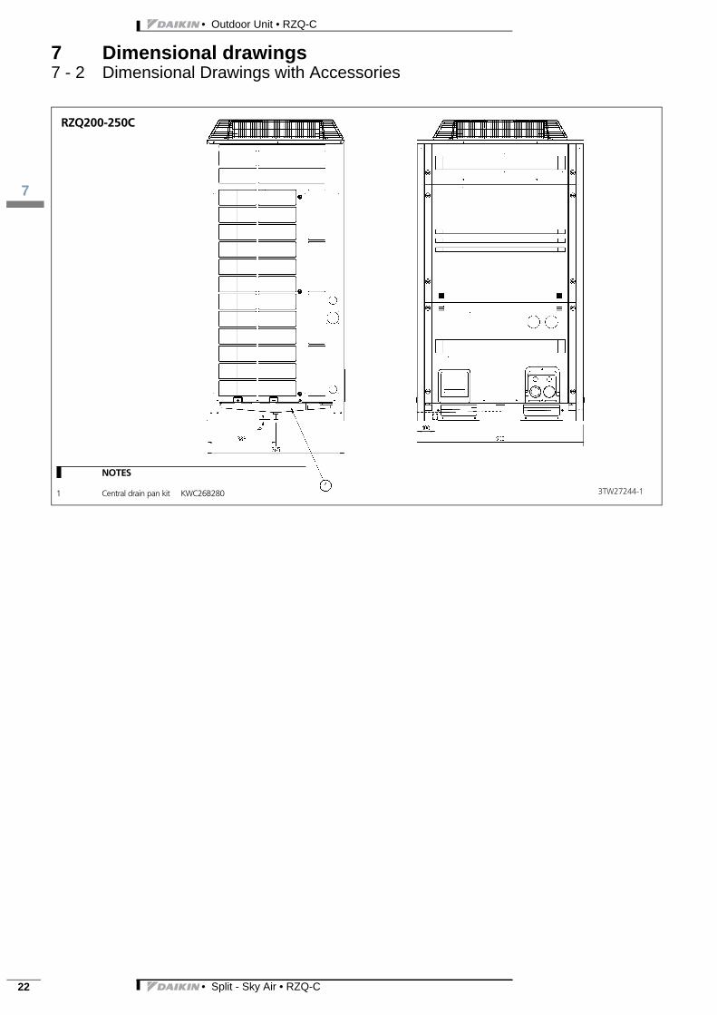
7 Dimensional drawings7 - 2 Dimensional Drawings with Accessories
• Split - Sky Air • RZQ-C
3
8
• Outdoor Unit • RZQ-C
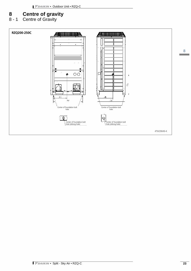
8 Centre of gravity8 - 1 Centre of Gravity
• Split - Sky Air • RZQ-C 23

• Outdoor Unit • RZQ-C
9
24
9 Piping diagrams9 - 1 Piping Diagrams
• Split - Sky Air • RZQ-C
3
9
• Outdoor Unit • RZQ-C
9 Piping diagrams9 - 2 Piping Diagram Twin Application
• Split - Sky Air • RZQ-C 25
• Outdoor Unit • RZQ-C
9
26
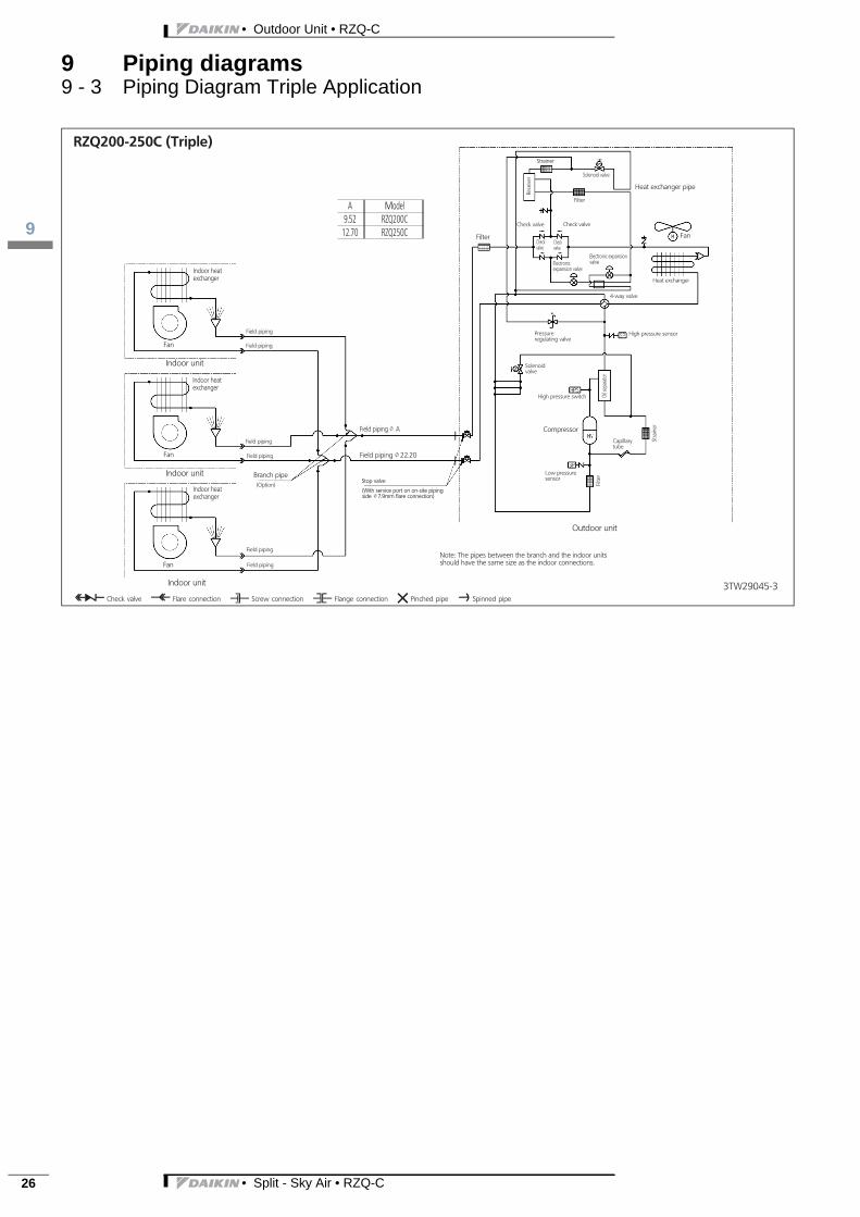
9 Piping diagrams9 - 3 Piping Diagram Triple Application
• Split - Sky Air • RZQ-C
3
9
• Outdoor Unit • RZQ-C
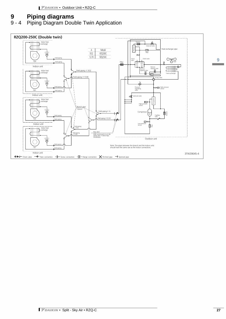
9 Piping diagrams9 - 4 Piping Diagram Double Twin Application
• Split - Sky Air • RZQ-C 27
• Outdoor Unit • RZQ-C
10
28
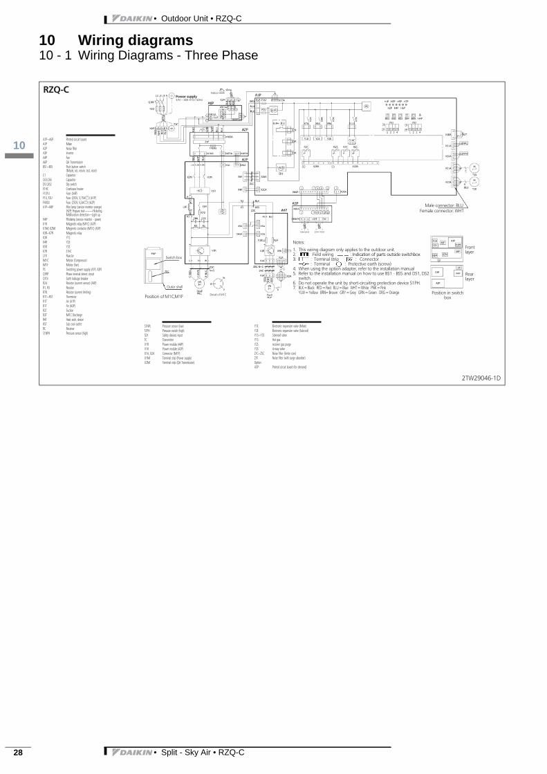
10 Wiring diagrams10 - 1 Wiring Diagrams - Three Phase
• Split - Sky Air • RZQ-C

3
11
• Outdoor Unit • RZQ-C
11 Sound data11 - 1 Sound Power Spectrum
• Split - Sky Air • RZQ-C 29

• Outdoor Unit • RZQ-C
11
30
11 Sound data11 - 2 Sound Pressure Spectrum - Cooling
• Split - Sky Air • RZQ-C

3
11
• Outdoor Unit • RZQ-C
11 Sound data11 - 3 Sound Pressure Spectrum - Heating
• Split - Sky Air • RZQ-C 31

• Outdoor Unit • RZQ-C
12
32
12 Installation12 - 1 Installation Method
• Split - Sky Air • RZQ-C

3
12
• Outdoor Unit • RZQ-C
12 Installation12 - 2 Fixation and Foundation of Units
• Split - Sky Air • RZQ-C 33

• Outdoor Unit • RZQ-C
13
34
13 Operation range13 - 1 Operation Range
• Split - Sky Air • RZQ-C

Daikin Europe N.V. participates in the Eu-rovent Certification programme for LiquidChilling Packages (LCP), Air handling units(AHU), Fan coil units (FCU) and variable re-frigerant flow systems (VRF) Check ongo-ing validity of certificate online:www.eurovent-certification.com or using:www.certiflash.com
EE
DE
N1
5-1
00
0
5/1
5 C
opy
righ
t Dai
kin
The
pre
sent
pu
blic
atio
n s
up
erse
des
EE
DE
N1
4-10
0
The present leaflet is drawn up by way of information only and does notconstitute an offer binding upon Daikin Europe N.V.. Daikin Europe N.V.has compiled the content of this leaflet to the best of its knowledge. Noexpress or implied warranty is given for the completeness, accuracy, re-liability or fitness for particular purpose of its content and the productsand services presented therein. Specifications are subject to changewithout prior notice. Daikin Europe N.V. explicitly rejects any liability forany direct or indirect damage, in the broadest sense, arising from or re-lated to the use and/or interpretation of this leaflet. All content is copy-righted by Daikin Europe N.V.
BARCODE Daikin products are distributed by:
Naamloze Vennootschap - Zandvoordestraat 300, B-8400 Oostende - Belgium - www.daikin.eu - BE 0412 120 336 - RPR Oostende