air compressor basics - wordpress.com
TRANSCRIPT

Maintenanceand Operation
ofAir Compressor Plants
NAVFAC MO-206January 1989
SN 0525-LP173-1715

ABSTRACT
This manual is directed to operators and supervisors whoactually perform and supervise operations and maintenance work.The manual is divided into five chapters with onecovering definitions and
chapterresponsibilities. Chapters two and
three cover positive displacement andrespectively.
dynamicChapter
compressors,four deals with auxiliary
while chapter five covers compressor controls.equipment,
manual provides guidelinesIn general, this
for maintenance and operation of aircompressor plants.

FOREWORD
This publication provides information on the maintenanceand operation of air compressor plants.
For maximum benefit, this manual should be used inconjunction with equipment manufacturers' manuals, parts listsand drawings. In case of conflict, manufacturers'recommendations on use, care, operations, adjustment and repairof specific equipment should be followed. The manual is ageneral guide which establishes standards for the operators,mechanics, and supervisors who are responsible for carrying outoperations and maintenance functions.
Additional information concerning procedures, suggestions,recommendations OK modifications that will improve this manualare continually invited and should be submitted throughappropriate channels to the Commander, Naval FacilitiesEngineering Command, (Attention: Code 165), 200 Stovall Street,Alexandria, VA 22332-2300.
This publication cancels and supersedes NAVAC MO-206 ofJanuary 1964 and any changes thereto. It has been reviewed andapproved in accordance with the Secretary of the NavyInstruction 5600.16A and is certified as an official publicationof the Naval Facilities Engineering Command.
C. M. MASKELLCaptain, CEC, U.S. NavyDeputy Commander forPublic Works

CHAPTER 1.
Section 1.
Section 2.
CHAPTER 2.
Section 1.
Section 2.
Section 3.
Section 4.
CONTENTS
DEFINITIONS AND RESPONSIBILITIES . . . . . . . . . . . . . .
AIR COMPRESSOR PLANT . . . . . . . . . . . . . . . . . . . . . . . . . .. . . . . . . . . .1 COMPONENTS OF AN AIR COMPRESSOR PLANT . . . . . . . . . . . . . . .2 AIR COMPRESSOR . . . . . . . . . . . . . . . . . . . . . . . . . . . . . . . . . . . . .3 AUXILIARY EQUIPMENT . . . . . . . . . . . . . . . . . . . . . . . . . . . .4 CONTROLS . . . . . . . . . . . . . . . . . . . . . . . . . . . . . . . . .5 COOLING WATER TREATMENT . . . . . . . . . . . . . . . . . . . . . . . .
OPERATION AND MAINTENANCE RESPONSIBILITIES . . . . . . . . . . .1 OPERATION . . . . . . . . . . . . . . . . . . . . . . . .2 DISASTER CONTROL . . . . . . . . . . . . . . . . . . . . . .3 OPERATOR MAINTENANCE . . . . . . . . . . . . . . . . . . .4 PREVENTIVE MAINTENANCE . . . . . . . . . . . . . . . . .5 BREAKDOWN MAINTENANCE . . . . . . . . . . . . . . . . . .6 COMPRESSED AIR SYSTEM LEAKS . . . . . . . . . . . . . . . . . . . . . .
POSITIVE DISPLACEMENT COMPRESSORS . . . . . . . . . . . . .
RECIPROCATING COMPRESSORS . . . . . . . . . . . . . . . . .1 DESCRIPTION . . . . . . . . . . . . . . . . . . . . . . .2 SAFETY PRECAUTIONS . . . . . . . . . . . . . . . . . . .3 STARTUP . . . . . . . . . . . . . . . . . . . . . . . . .4 NORMAL OPERATION . . . . . . . . . . . . . . . . . . . . . 5 SHUTDOWN . . . . . . . . . . . . . . . . . . . . . . . . . . . . . . . . . 6 OPERATIONAL PREVENTIVE MAINTENANCE . . . . . . . . . . . . . .7 PREVENTIVE MAINTENANCE INSPECTION . . . . . . . . . . . .8 MAINTENANCE . . . . . . . . . . . . . . . . . . . . . . .
ROTARY SLIDING VANE COMPRESSORS. . . . . . . . . . . . . .1 DESCRIPTION . . . . . . . . . . . . . . . . . . . . . . .2 STARTUP . . . . . . . . . . . . . . . . . . . . . . . . .3 NORMAL OPERATION. . . . . . . . . . . . . . . . . . . .4 SHUTDOWN . . . . . . . . . . . . . . . . . . . . . . . . . . . . . . . . 5 OPERATIONAL PREVENTIVE MAINTENANCE . . . . . . . . . . . . . . .6 PREVENTIVE MAINTENANCE INSPECTION . . . . . . . . . . . . . .7 MAINTENANCE . . . . . . . . . . . . . . . . . . . . . . . . . . .
ROTARY TWIN-LOBE COMPRESSORS . . . . . . . . . . . . . . . .1 DESCRIPTION . . . . . . . . . . . . . . . . . . . . . . .2 STARTUP . . . . . . . . . . . . . . . . . . . . . . . . .3 NORMAL OPERATION . . . . . . . . . . . . . . . . . . .4 SHUTDOWN . .. . . . . . . . . . . . . . . . . . . . . . . . . . . . . . . 5 OPERATIONAL PREVENTIVE MAINTENANCE . . . . . . . . . . . . . .6 PREVENTIVE MAINTENANCE INSPECTION. .. . . . . . . . . . . . .7 MAINTENANCE . . . . . . . . . . . . . . . . . . . . . . .
ROTARY LIQUID PISTON COMPRESSORS . . . . . . . . . . . . . .1 DESCRIPTION . . . . . . . . . . . . . . . . . . . . . . .2 STARTUP . . . . . . . . . . . . . . . . . . . . . . . . . . . . . . . . . . . . . . . .
Page
l-l
l-ll-ll-ll-ll-3l-4
l-5l-5l-5l-6l-7l-71-7
2-l
2 - l2 - l2-l2-32-52-52-62-62-8
2-132-132-132-152-152-162-162-17
2-192-192-192-212-212-212-212-22
2-232-232-23

CHAPTER 3.
CHAPTER 4.
Section 1.
Section 2.
Section 3.
Section 4.
Section 5.
Section 6.
CONTENTS (Continued)
Page
3 NORMAL OPERATION . . . . . . . . . . . . . . . . . . . . . . . . . . . . 2-234 SHUTDOWN . . . . . . . . . . . . . . . . . . . . . . . . . . . . . . . . . . . .2-235 OPERATIONAL PREVENTIVE MAINTENANCE . . . . . . . . . . . . . . . . 2-256 PREVENTIVE MAINTENANCE INSPECTION . . . . . . . . . . . . . . . . . . 2-257 MAINTENANCE . . . . . . . . . . . . . . . . . . . . . . . . . . 2-26
DYNAMIC COMPRESSORS . . . . . . . . . . . . . . . . . . . . . . . 3-l1 DESCRIPTION . .. . . . . . . . . . . . . . . . . . . . . . . 3-l2 STARTUP . . . . . . . . . . . . . . . . . . . . . . . . . 3-33 NORMAL OPERATION . . . . . . . . . . . . . . . . . . . . . . . . . . 3-54 SHUTDOWN . . . . . . . . . . . . . . . . . . . . . . . . . . . . . . . . . . 3-55 OPERATIONAL PREVENTIVE MAINTENANCE . . . . . . . . . . . . . . . . . . . 3-76 PREVENTIVE MAINTENANCE INSPECTION . . . . . . . . . . . . . . . . 3-87 MAINTENANCE . . . . . . . . . . . . . . . . . . . . . . . 3-9
AUXILIARY EQUIPMENT . . . . . . . . . . . . . . . . . . . . 4-l
INTAKE FILTERS. . . . . . . . . . . . . . . . . . . . . . . 4-l1 DESCRIPTION . . . . . . . . . . . . . . . . . . . . . . .4-l2 INSPECTION . . . . . . . . . . . . . . . . . . . . . . . 4-l3 MAINTENANCE . . . . . . . . . . . . . . . . . . . . . . . 4-2
SILENCERS 4-51 DESCRIPTION . . . . . . . . . . . . . . . . . . . . . . . . . . . . . . . . . . . . 4-52 INSPECTION AND MAINTENANCE . . . . . . . . . . . . . . . . . . . . 4-5
INTERCOOLERS AND AFTERCOOLERS. . . . . . . . . . . . . . . 4 - 71 DESCRIPTION . . . . . . . . . . . . . . . . . . . . . . . . . . . . . . .. . . . 4 - 72 STARTUP . . . . . . . . . . . . . . . . . . . . . . . . . . . . 4 - 83 NORMAL OPERATION . . . . . . . .. . . . . . . . . . . . . . . 4 - 84 SHUTDOWN . . . . . . . . . . . . . . . . . . . . . . . . . . . . . . . . . . . .4 - 95 OPERATIONAL PREVENTIVE MAINTENANCE . . . . . . . . . . . . . . . . . . 4 - 96 PREVENTIVE MAINTENANCE INSPECTION . . . . . . . . . . . . 4 - 97 MAINTENANCE . . . . . . . . . . . . . . . . . . . . . . . 4-11
SEPARATORS . . . . . . . . . . . . . . . . . . . . . . . . . 4-131 DESCRIPTION . . . . . . . . . . . . . . . . . . . . . . . . . . . . . . . . 4-132 OPERATION . . . . . . . . . . . . . . . . . . . . . . . 4-133 PREVENTIVE MAINTENANCE INSPECTION . . . . . . . . . . . . . . . 4-134 MAINTENANCE . . . . . . . . . . . . . . . . . . . . . . . 4-14
TRAPS . . . . . . . . . . . . . . . . . . . . . . . . . . . . . . . . . . . . . . . . . 4-151 DESCRIPTION . . . . . . . . . . . . . . . . . . . . . . . .. . . . 4-152 STARTUP . . . . . . . . . . . . . . . . . . . . . . . . . . . . . . . . . . . . 4-153 SHUTDOWN . . . . . . . . . . . . . . . . . . . . . . . . . . . . . . . . . . . 4-154 PREVENTIVE MAINTENANCE INSPECTION . . . . . . . . . . . . . . . . 4-155 MAINTENANCE . . . . . . . . . . . . . . . . . . . . . . . 4-15
AIR RECEIVERS . . . . . . . . . . . . . . . . . . . . . . .4-191 DESCRIPTION . . . . . . . . . . . . . . . . . . . . . . . 4-19
ii

CONTENTS (Continued)
Page2 NORMAL OPERATION . . . . . . . . . . . . . . . . . 4-193 PREVENTIVE MAINTENANCE INSPECTION . . . . . . . . . 4-194 MAINTENANCE . . . . . . . . . . . . . . . . . . . . 4-20
Section 7. DRYERS . . . . . . . . . . . . . . . . . . . . . . . 4-211 DESCRIPTION . . . . . . . . . . . . . . . . . . . . 4-212 TYPES . . . . . . . . . . . . . . . . . . . . . . . 4-213 NORMAL OPERATION . . . . . . . . . . . . . . . . . 4-234 PREVENTIVE MAINTENANCE INSPECTION . . . . . . . . . 4-245 MAINTENANCE . . . . . . . . . . . . . . . . . . . . 4-25
CHAPTER 5. CONTROLS.. . . . . . . . . . . . . . ......................
Section 1.1234567
PRIME MOVER CONTROLS . . . . . . . . . . . . . . . .DESCRIPTION . . . . . . . . . . . . . . . . . . . .STARTUP . . . . . . . . . . . . . . . . . . . . . .NORMAL OPERATION . . . . . . . . . . . . . . . . .SHUTDOWN . . . . . . . . . . . . . . . . . . . . .OPERATIONAL PREVENTIVE MAINTENANCE . . . . . . . .PREVENTIVE MAINTENANCE INSPECTION . . . . . . . . .MAINTENANCE . . . . . . . . . . . . . . . . .
5-l
5-l5-l5-45-45-45-45-55-5
Section 2. COMPRESSOR CONTROLS . . . . . . . . . . . . . . . . 5-71 CAPACITY CONTROL . . . . . . . . . . . . . . . . . 5-72 STARTUP . . . . . . . . . . . . . . . . . . . . . . 5-153 NORMAL OPERATION . . . . . . . . . . . . . . . . . 5-154 SHUTDOWN . . . . . . . . . . . . . . . . . . . .5 OPERATIONAL PREVENTIVE MAINTENANCE
5-15. . . . . . . . 5-15
6 PREVENTIVE MAINTENANCE INSPECTION . . . . . . . . . 5-157 MAINTENANCE . . . . . . . . . . . . . . . . . . . . 5-16
REFERENCES . . . . . . . . . . . . . . . . . . . . . . . . Reference-l
APPENDIX A - ABBREVIATIONS AND ACRONYMS . . . . . . . . . . . . A-l
APPENDIX B - EVALUATION OF LOSSES IN COMPRESSED AIR SYSTEMS. . . B-l1 COMPRESSED AIR SYSTEM LEAKS . . . . . . . . . . . . B-22 TEST METHOD . . . . . . . . . . . . . . . . . . . . B-23 TEST EQUIPMENT . . . . . . . . . . . . . . . . . . . . . . . . B-24 TEST PRECAUTIONS . . . . . . . . . . . . . . . . . . . . . . B-25 TEST PROCEDURES . . . . . . . . . . . . . . . . . B-26 CORRECTIVE MEASURES . . . . . . . . . . . . . . . . B-6
INDEX . . . . . . . . . . . . . . . . . . . . . . . . . . . .Index-1
iii

FIGURES
Figure Page
1-12-12-22-32-42-52-62-7
2-82-92-102-113-l3-23-33-43-53-63-74-14-24-34-44-54-64-74-84-94-104-115-15-25-35-45-55-65-7B-1
Table
1-11-2B-1B-2B-3
Main Components of an Air-Compressor Plant. . . . . . . .Two-Cylinder, Two-Stage, V-Type Air Compressor . . . . .Installing Piston Rings . . . . . . . . . . . . . . . . .Connecting Rod With Wedge Adjusting Bearings . . . . . .Connecting Rod Assembly . . . . . . . . . . . . . . . . .Method of Checking the Tension of V-Belts . . . . . . . .Cross Section of Rotary Sliding Vane Compressor . . . . .Cutaway View of Two-Stage, Rotary Sliding VaneCompressor. . . . . . . . . . . . . . . . . . . . . . . .Impeller Arrangement of Rotary Twin-Lobe Compressor . . .Rotary Twin-Lobe Compressor . . . . . . . . . . . . . . .Compression Cycle, Rotary Liquid Piston Compressor. . . .Functional Elements, Rotary Liquid Piston Compressor. ..Simple Volute Pump . . . . . . . . . . . . . . . . . . .Six-Stage Compressor . . . . . . . . . . . . . . . . . .Impeller Design . . . . . . . . . . . . . . . . . . . . .Axial Flow Compressor . . . . . . . . . . . . . . . . . .Rotor and Stator Blades, Axial Compressor . . . . . . . .Alignment Setup . . . . . . . . . . . . . . . . . . . . .Coupling Alignment and Misalignment . . . . . . . . . . .Oil-Bath Intake Filter . . . . . . . . . . . . . . . . .Compressor Intake Silencer . . . . . . . . . . . . . . .Air-Cooled Heat Exchanger . . . . . . . . . . . . . . . .Water-Cooled Heat Exchanger . . . . . . . . . . . . . . .Centrifugal Type Separator . . . . . . . . . . . . . . .Baffle Type Separator . . . . . . . . . . . . . . . . . .Drain Traps . . . . . . . . . . . . . . . . . . . . . . .Air Receiver . . . . . . . . . . . . . . . . . . . . . .Flow Diagram of Electric Reactivated Absorption Dryer . .Deliquescent (Absorption) Dryer . . . . . . . . . . . . .Flow Diagram of Refrigeration Dryer . . . . . . . . . . .Automatic Start-Stop Governor . . . . . . . . . . . . . .Variable Speed, Oil Relay Governor . . . . . . . . . . .Inlet Valve Unloader . . . . . . . . . . . . . . . . . .Airflow Diagram of Compressor With Five-Step Control . .Three-Way Solenoid Valve . . . . . . . . . . . . . . . .Five-Step Clearance Control . . . . . . . . . . . . . . .Intake Unloader for Rotary Sliding Vane Compressor . . .Loss (cfm) vs Pressure (psig) . . . . . . . . . . . . . .
TABLES
Title Page
Maximum Pressures and Capacities of Air Compressors . . . 1-3Troubleshooting Chart . . . . . . . . . . . . . . . . . . 1-8Amount and Cost of Air Leaks . . . . . . . . . . . . . . B-3Pressure Test Data . . . . . . . . . . . . . . . . . . . B-4Calculation of Losses . . . . . . . . . . . . . . . . . . B-4
iv
l-22-22-9
2-102-112-112-13
2-142-202-202-242-253-l3-23-23-33-43-113-124-24-54-74-8
4-134-144-164-194-214-224-235-25-35-85-9
5-105-115-13B-6

SAFETY SUMMARY
Whenever work is to be accomplished on air compressor plants there isalways the possibility of a hazardous situation occurring, which could resultin serious injury to or death of personnel. Performance without injury is asign of conscientious workmanship and planned supervision. Therefore, safetyis a primary consideration when operating, inspecting, or maintaining any ofthe air compressor plants addressed in this publication.
The first essential action is to read and understand all publicationsassociated with the systems and equipment being used. The manuals explainsafe and accepted ways of installation, startup, operation, inspection,maintenance, removal, and shutdown. If you do not understand what you haveread, DO NOT attempt to perform the intended task; get guidance from yoursupervisor.
The following safety rules are emphasized:
GENERAL
• All personnel should be trained and qualified in cardiopulmonaryresuscitation (CPR).
• All personnel should wear safety shoes.
• All personnel should wear clothing appropriate to the job beingperformed. Eliminate loose clothing, which can get caught inmachinery.
• Wear hardhats when required.
• All personnel should wear eye and ear protection prescribed for thetask being performed.
• Report all injuries, even if they seem to be minor.
• DO NOT WORK ALONE. At least one other person should be on hand toprovide assistance, if needed.
• Always use the correct tool for the job.
• Prevent skin ruptures and sensory injuries when working withcompressed air. Close isolation valves before working on lines orfittings.
• Follow lockout and tagout procedures prescribed for the plant.
• Current and accurate drawings of various mechanical systems areessential for operational safety of the plant.
ELECTRICAL WORK
• Do not wear jewelry, including rings, bracelets, necklaces, or wristwatches.
v

• Do not wear jackets with metal zippers.
• Do not use metal ladders.
• Do not take short cuts. The steps recommended by a manufacturerusually have a margin of safety built into them.
• Do not try to connect meters to circuits unless you are qualified.Wait for an electrician.
• Always use insulated tools and grounded equipment. NEVER USEscrewdrivers or other tools with metal shanks extending through thehandle.
• Always use and observe tags and lockouts on circuits being worked on.
WARNINGS AND CAUTIONS
Warnings and cautions appear in equipment manuals. A CAUTION is astatement regarding an operating or maintenance procedure, practice, orcondition which, if not strictly observed, could result in damage to, ordestruction of, equipment or data, loss of mission effectiveness, or long-termhealth hazards to personnel. A WARNING is a statement regarding an operatingor maintenance procedure, practice, or condition which, if not strictlyobserved, could result in injury to, or death of, personnel.
The warnings and cautions which appear in this manual are repeated herefor emphasis and reinforcement of their need to be observed explicitly. Thenumbers in parentheses at the end of each warning and caution indicate thepage on which it appears; for example, (4-15) refers to page 4-15.
Do not use gasoline, kerosene, or other low flashpoint solvents. Aserious explosion m a y result. (2-8, 3-10, 4-3, 4-6, 4-15, 4-20,5-5, 5-16)
If impellers are to be rotated, keep hands, feet, loose clothing,and foreign objects away from inlet and discharge openings, asserious personal injury or damage to equipment can occur. (2-19)
Do not operate equipment without adequate silencing devices. Highnoise levels may cause permanent hearing damage. (2-19)
Compressor equipment, compressed air, and electricity can bedangerous. To prevent injury, before attempting any maintenance becertain the compressor cannot be started accidentally. (3-3)
vi
Protective devices must be worn to avoid damage to hearing. (3-4)
Do not attempt to repair or remove any compressor system partswithout first relieving pressure from the entire system. (4-9,4-14, 4-15, 4-20, 4-24, 4-25, 4-26)
Never operate compressor in the critical speed range (insufficientvolume at the compressor inlet to permit stable operation); surgingor pumping will occur. Operation under these conditions may resultin equipment damage. (3-5)
To avoid damage to equipment, after shutting down the drive, keepauxiliary lubricating oil pump operating until bearings have cooledto ambient temperatures. (3-5)
To avoid internal damage to equipment, use only synthetic spongeswhen cleaning internal surfaces and components. Do not use clothrags or cotton waste. (3-10)
To ensure proper alignment, check alignment in both the hot and coldcondition. After checking the alignment in the cold condition,operate the compressor under full load for 1 hour. Shut down theunit and recheck the alignment immediately. (3-10)
Dry type filter elements can easily be damaged allowing harmfulparticulates to pass. If in doubt about correct cleaningprocedures,replace the filter element. (4-2)
Ensure all joints are tight to avoid entry of unfiltered air. Dirtin the air will cause premature wear to the compressor. (4-6)
Never hammer on the tubes or use sharp edged scrapers which maydamage the tubes. (4-11)
Chemical solutions used for cleaning should be capable of dissolvingthe scale or other deposits without attacking the metal. (4-11)
vii

Do not overrun the unit. Overrunning will result in the towerbecoming saturated and unable to absorb any more moisture. Moistureladen air will then be carried over into the distribution system.(4-23)
On systems where oil carryover from the compressor is present,provision should be made to protect the desiccant bed of the dryerfrom becoming oil saturated. Oil deposits in the desiccant bedcause a decrease in drying efficiency and necessitate frequentreplacement of the desiccant.(4-23)
Do not attempt to service the sealed refrigeration unit; damage tothe unit may result. Contact the manufacturer in the event of anymalfunction. (4-26)
The operator must have a thorough understanding of the controlsystem and its operation. (5-4, 5-15)
vii

CHAPTER 1. DEFINITIONS AND RESPONSIBILITIES
Section 1. AIR COMPRESSOR PLANT
1 COMPONENTS OF AN AIR COMPRESSOR PLANT. Compressed air is a form of powerthat has many important uses in industrial activities. Air compressor plantsare used to provide an adequate quantity of compressed air at sufficientpressure to various points of application. Distribution of compressed air isfound in NAVFAC MO-209, Maintenance of Steam, Hot Water, and Compressed AirDistribution Systems. Components of a plant are: air compressor, intercool-ers, aftercoolers, moisture separator, air receiver, and controls (figure l-l).
2 AIR COMPRESSOR. The air compressor is the heart of a compressed airplant. Compressors are used to increase the pressure of air from the initialconditions (air intake) to the discharge conditions (air discharge).Compressors may be used as vacuum pumps. A vacuum pump has an intake that isbelow atmospheric pressure and usually compresses to no higher thanatmospheric pressure. The degree of vacuum attainable is dependent upon thetype of system, leakage into the system, and limitations of the equipment.The main types of air compressors are positive displacement and dynamic.
2.1 Positive Displacement Compressors. There are two basic types of positivedisplacement compressors. In one, air is compressed as the volume of theenclosed space is reduced. In the other, a definite quantity of air istrapped and transferred from the suction intake to the discharge port withoutreducing its volume. Pressure increase is caused by backflow into the casingwhen the discharge port is uncovered. Examples of the first type arereciprocating compressors, rotary sliding vane compressors, and rotary liquidpiston compressors. An example of the second type is the rotary twin-lobecompressor. Refer to chapter 2 for details.
2.2 Dynamic Compressors. Dynamic compressors operate by imparting velocityand pressure to the admitted air, through the action of a rapidly spinningimpeller or rotating vanes. The main types of dynamic compressors arecentrifugal and axial compressors. Refer to chapter 3 for details.
2.3 Maximum Pressures and Capacities of Air Compressors. The approximatemaximum pressures in pounds-force per square inch gauge (psig), and theapproximate maximum capacities in cubic feet per minute (cfm) for varioustypes of compressors are given in table l-l.
3 AUXILIARY EQUIPMENT. The following auxiliary equipment is required for theproper operation of an air compressor plant.
3.1 Air Intake Filters. Filters prevent the admission of atmospheric dust tothe air compressor. Refer to chapter 4, section 1 for details.
3.2 Silencers. Silencers reduce objectionable compressor suction noise.Refer to chapter 4, section 2.
3.3 Intercoolers and Aftercoolers. Intercoolers are used between consecutivestages of multistage compressors to remove the heat of compression.Aftercoolers are installed on the compressor discharge lines to remove theheat of compression after compression is completed. Both are effective in
1-1

FIGURE l-l. Main Components of an Air Compressor Plant
1-2

TABLE l-l. Maximum Pressures and Capacities of Air Compressors
Compressor Maximum Pressure Maximum CapacityType (psig) (cfm)
Reciprocating 100,000 26,000
Rotary sliding vane 400 6,000
Rotary twin-lobe 20 32,800
Rotary liquid piston 100 16,000
Centrifugal 5,500 650,000
Axial 500 1,000,000
removing moisture and oil from the compressed air. Refer to chapter 4,section 3.
3.4 Separators. Separators remove and collect entrained water and oilprecipitated from the air. Refer to chapter 4, section 4.
3.5 Traps.Traps drain condensed moisture and oil from separators,intercoolers, aftercoolers, receivers, and distribution piping. Refer tochapter 4, section 5.
3.6 Air Receivers. Air receivers are tanks wherein compressed air isdischarged and stored. They help to reduce pulsations in the discharge lineand provide storage capacity to meet peak demands exceeding the capacity ofthe compressor. Refer to chapter 4, section 6.
3.7 Air Dryers. Air dryers remove moisture that might condense in air lines,air tools, or pneumatic instruments. Refer to chapter 4, section 7.
3.8 Safety Valves. Safety valves are used in a compressed air or gassystem. They must open rapidly and fully so that excessive pressure buildupcan be relieved immediately to prevent damage or destruction of the systemcomponents. Although the terms safety valve and relief valve are often usedinterchangeably, this is technically incorrect. A relief valve is used withliquid systems. Since liquids are virtually incompressible, a relief valve isdesigned to open gradually as the venting of a small amount of liquid is oftensufficient to relieve excessive pressure throughout the system. There is oneclass of valve known as a safety-relief valve that can be used as either typedepending upon internal adjustments. Safety valves are found in interstages,air receivers, and between a positive displacement compressor and any shutoffvalve.
4 CONTROLS. Control systems for air compressors vary from the relativelysimple to the extremely sophisticated. The simpler control systems, throughthe use of sensors, monitor the performance of the equipment and, through the
l-3
use of lights and/or audible signals, alert an operator that some variable isoutside the normal operating range. Most systems automatically initiate ashutdown procedure under certain conditions to prevent equipment damage. Withincreasing use of remote,unattended compressor installations, the demand forthe highest degree of protection and reliability has brought about manyadvancements and lessened the need for operator involvement. Many controlsystems provide a completely automatic sequence for starting, operating, andshutdown of compressors. The more advanced control systems are able tooptimize equipment efficiency by controlling one or more variables to obtain aspecified level of performance.
5 COOLING WATER TREATMENT. Cooling water systems are used in compressed airplants to remove heat from engines, air compressors, refrigeration condensers,intercoolers, and aftercoolers. These cooling systems are classified aseither once-through or recirculating. Once-through systems often requirenothing more than chlorination to prevent biological fouling of heatexchangers. Treatment is more critical in open recirculating systems becauseof solids buildup due to evaporation. As hardness and other solids increase,probability of mineral scale formation in heat exchangers increases. Tocombat scale damage, chemical additives are used to keep scale-forming saltsin solution. Dissolved oxygen and carbon dioxide are prime corrosiondevelopers. Corrosion control is provided by addition of inhibitors. Slimeaccumulation and fouling may be prevented by the addition of chlorine or otherbiocides. Solids concentration is controlled by blowdown. More detailedinformation on cooling water treatment is contained in the proposedpublication, NAVFAC MO-225, Industrial Water Treatment.
l-4

Section 2.OPERATION AND MAINTENANCE RESPONSIBILITIES
1 OPERATION. Operation includes startup, normal operation, emergencyoperation, and shutdown of plant equipment. Good operation is safe, reliable,and economical. Operators and operator supervisors are responsible for safeand efficient operation of equipment. Follow these basic rules of goodoperation.
• All operators should be thoroughly familiar with the equipment andsystems they operate. Carefully study drawings, diagrams, instructionmanuals, special operation procedures, and emergency procedures. Knowthe location, method of operation, and function of all valves,switches, electrical controls, and other control devices.
• Perform work assignments in a safe manner in accordance with approvedoperating procedures. Use available protective safety clothing andequipment.
• Operate equipment and systems economically, safely, and reliably.
• Teamwork and cooperation are essential.
• Be alert and concentrate on your work. Errors and forgetfulness cancause serious personnel injuries and costly damage to equipment.
2 DISASTER CONTROL. Disaster control includes the prevention, minimization,and correction of operational and emergency casualties to plant facilities andinstallations. Sound design, careful inspection, and effective organizationand training of plant personnel are part of a disaster control program. Allplant personnel are responsible for disaster control as follows:
(a) The responsibilities of the operators are:
• Operating the plant equipment in a safe and reliable manner
• Handling emergencies and casualties effectively using approvedprocedures
• Reporting immediately to their supervisors any equipment defectsor operational deficiencies
(b) The responsibilities of the maintenance personnel are:
• Maintaining the equipment in good condition at all times
• Making quick effective repairs when equipment breakdowns occur
(c) The responsibilities of the supervisory and engineering personnelare:
• Selection of competent personnel
• Preparation and supervision of adequate personnel trainingprograms
l-5
• Preparation and supervision of an adequate plant maintenance,housekeeping, and inspection program
• Competent design and installation of all plant equipment
• Preparation and supervision of normal operating procedures thatare safe, reliable, and economical
• Preparation and supervision of emergency and casualty procedures
• Preparation and procurement of training aids, system diagrams,and manufacturers' manuals for the training and guidance ofoperating and maintenance personnel
• Preparation and supervision of a periodic test and inspectionprogram for all plant safety devices, fire fighting equipment,and other emergency equipment
3 OPERATOR MAINTENANCE. Operator maintenance is the necessary routine,recurring maintenance work performed by the operators to keep the equipmentoperating at its designed capacity and efficiency.
3.1 Responsibilities. The operator is an important member of the maintenanceteam. A well-informed and responsible operator performs the following duties:
• Keeps equipment in service for maximum periods
• Detects any flaws so that equipment is removed from service in time toprevent serious damage
• Performs minor repairs on equipment removed from service to minimizedown time
3.2 Duties. Everyone in the operating chain should be aware of the followingconditions.
(a) Cleanliness. Dirt is the principal cause of equipment failure andshould be removed immediately by the operator.
(b) Lubrication. Any two surfaces brought together develop friction.When not properly lubricated, these surfaces wear down, change clearances, andcause equipment breakdowns.
(c) Temperature Change. Any unusual temperature change which theoperator cannot correct should be reported immediately to the plantsupervisor. When the temperature of a piece of equipment rises rapidly,immediately shut it down.
(d) Vibration. Vibration is a major source of equipment failure.,Equipment not properly secured will vibrate. This vibration causes looseningof components and possible misalignment of parts, leading to more seriousproblems. The operator,in making rounds, should check the bearings,
l-6
compressor housing, and motor casing for any unusual sound, vibration, ormotion. Take immediate action to correct any problems.
4 PREVENTIVE MAINTENANCE. Preventive maintenance (PM) is a system of routineinspections of equipment recorded for future reference on inspection records.Its purpose is to anticipate and prevent possible equipment failures by makingperiodic inspections and minor repairs in advance of major operatingdifficulties.
4.1 Responsibilities. PM is the responsibility of the operators andspecified maintenance crews. The operator is expected to do as muchmaintenance as his technical abilities, tools, and time allows. Specificallyassigned maintenance crews work on equipment requiring no operator, or wherethe work to be done is beyond the scope of the operator.
4.2 Scheduling. Scheduling PM is the responsibility of the plantsupervisor. Maintain a record card for each major piece of equipment withentries of the PM schedule, inspections, and operation. See NAVFAC MO-322,Inspection of Shore Facilities, for more detailed information.
5 BREAKDOWN MAINTENANCE. Breakdown maintenance is the emergency repair ofinoperable equipment performed by operators or maintenance crews. The plantand maintenance supervisors are responsible for emergency repairs. TheUtility and Maintenance Shops should develop a coordinated plan to efficientlyhandle emergency breakdowns.
5.1 Troubleshooting. Troubleshooting is a means of locating the source oftrouble when problems occur so that repairs can be made. Compressormanufacturers will normally provide troubleshooting charts for theirequipment. These charts can be very helpful in diagnosing problems. Tablel-2 is an example of a typical, but partial, troubleshooting chart. Thistroubleshooting table is not meant to be a complete source of information. Itis a composite list developed from the manufacturers of various types ofcompressors and compressor system components. The list contains some commonlyfound problems, possible causes, and remedies.
6 COMPRESSED AIR SYSTEM LEAKS. A malfunction which may affect the demandupon a compressed air plant is a loss of air within the distribution system.A discussion of the evaluation of losses in compressed air systems ispresented in appendix 8.
l-7

TABLE l-2. Troubleshooting Chart
Problem Possible Cause Remedy
Compressor unitwill not start
No power to motor. Turn on power.
Unloaders not operating. Repair unloaders.
Obstruction to rotation.
Repair or readjustcontrols.
Remove obstruction.
Motor Discharge pressure aboveoverheating rating.
Unloader setting incorrect.
Inlet filter clogged.
Readjust control.
Readjust unloader.
Clean or replace filter.
Overheating of Discharge pressure abovecompressor rating.parts
Intake filter clogged.
Worn or broken valves.
Leaking gaskets.
Lower discharge pressure.
Clean.
Replace.
Replace.
Unloader or control defective. Replace.
Unloader setting wrong.
Compressor components worn or broken.
Cylinder head, intercooler dirty.
Insufficient cooling water.
V-belt or coupling misalign-ment.
Bearings too tight.
Oil level too high.
l-8
Correct.
Replace.
Clean.
Increase quantity ofcooling water.
Realign components.
Adjust bearings.
Correct oil level.
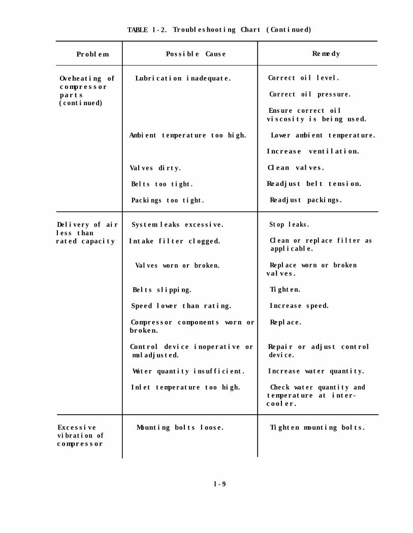
TABLE l-2. Troubleshooting Chart (Continued)
Problem Possible Cause Remedy
Oveheating of Lubrication inadequate. Correct oil level.compressorparts Correct oil pressure.(continued)
Ensure correct oilviscosity is being used.
Ambient temperature too high. Lower ambient temperature.
Increase ventilation.
Valves dirty. Clean valves.
Belts too tight. Readjust belt tension.
Packings too tight. Readjust packings.
Delivery of air System leaks excessive. Stop leaks.less thanrated capacity Intake filter clogged. Clean or replace filter as
applicable.
Valves worn or broken. Replace worn or brokenvalves.
Belts slipping. Tighten.
Speed lower than rating. Increase speed.
Compressor components worn or Replace. broken.
Control device inoperative or Repair or adjust control maladjusted. device.
Water quantity insufficient. Increase water quantity.
Inlet temperature too high. Check water quantity and temperature at inter-
cooler.
Excessive Mounting bolts loose.vibration of compressor
Tighten mounting bolts.
l-9
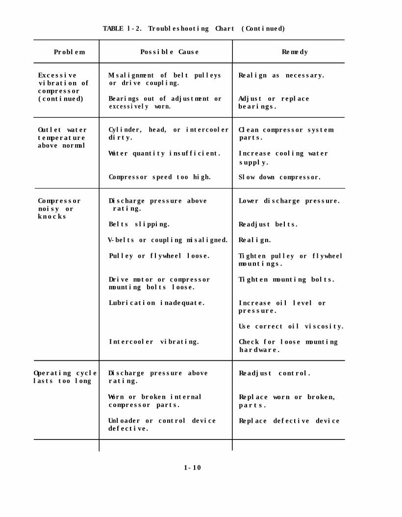
TABLE l-2. Troubleshooting Chart (Continued)
Problem Possible Cause Remedy
Excessivevibration ofcompressor(continued)
Outlet watertemperatureabove normal
Misalignment of belt pulleysor drive coupling.
Bearings out of adjustment orexcessively worn.
Realign as necessary.
Adjust or replacebearings.
Cylinder, head, or intercooler Clean compressor systemdirty. parts.
Water quantity insufficient. Increase cooling watersupply.
Compressor speed too high. Slow down compressor.
Compressornoisy orknocks
Discharge pressure aboverating.
Belts slipping.
V-belts or coupling misaligned.
Pulley or flywheel loose.
Drive motor or compressormounting bolts loose.
Lubrication inadequate.
Intercooler vibrating.
Lower discharge pressure.
Readjust belts.
Realign.
Tighten pulley or flywheelmountings.
Tighten mounting bolts.
Increase oil level orpressure.
Use correct oil viscosity.
Check for loose mountinghardware.
Operating cyclelasts too long
Discharge pressure above Readjust control.rating.
Worn or broken internal Replace worn or broken,compressor parts. parts.
Unloader or control device Replace defective devicedefective.
1-10

TABLE l-2.Troubleshooting Chart (Continued)
Problem Possible Cause Remedy
Air receiver Unloader or control defective. Repair or replacepressure above defective parts.normal
Unloader setting wrong. Correct unloader setting.
Leaks in control air piping. Stop leaks.
Control air line clogged. Unclog control air lines.
Intercoolerpressure abovenormal
Valves worn or broken. Replace valves.
Valves not seated or Reseat or relocate valves.incorrectly located.
Unloader setting wrong. Correct unloader setting.
Intercooler passages clogged. Clean intercooler.
Insufficient water. Increase water supply.
Intercooler System demand exceeds rating. Upgrade compressor.pressure below normal System leakage excessive. Stop leakage.
Intake filter clogged.
Valves worn or broken.
Unloader setting wrong.
Clean or replace air filter as applicable.
Replace worn or brokenvalves.
Correct unloader setting.
Air in receiver Moisture separator nottoo moist draining.
Air coolers ineffective.
Unclog or repair separatordrain.
Check temperature ofcooler at discharge port.
Inadequate cooling waterflow Check cooling waterflowrate. pressure.
1-11

TABLE l-2. Troubleshooting Chart (Continued)
Problem Possible Cause Remedy
Oil in air Clogged air filter. Clean or replace airreceiver filter element.
Broken piston and/or rings. Replace broken parts.
Oil level too high. Correct oil level.
Oil viscosity incorrect. Change lubricant to properviscosity.
Oil wrong type. Change lubricant to properviscosity.
Unloaded running time too Use auto start/stoplong. control.
Surging of Operating at less than Increase flow ofdistribution designed minimum flow. compressor.air
Install surge controlvalve in discharge line.
Cavitation of Feedwater level too low. Increase feedwater levelwater in in reservoir.cooling supply
Air leaks into suction piping. Stop leaks.
1-12

CHAPTER 2. POSITIVE DISPLACEMENT COMPRESSORS
Section 1. RECIPROCATING COMPRESSORS
1 DESCRIPTION. Reciprocating air compressors are manufactured in a varietyof shapes, sizes, and capacities. Single-stage machines draw air from theatmosphere and discharge it into the receiver or storage tank. Two-stagecompressors (figure 2-l) bring the air up to intermediate pressure in onecylinder and to final pressure in a second cylinder. Where two or more stagesare employed, the unit is defined as a multistage air compressor. Multistagecompressors produce higher discharge pressures. Stationary air compressorsare usually water-cooled, with the exception of small units that areair-cooled. Portable units are also usually air-cooled. Air-cooledcompressors utilize finned cylinders to increase the radiating area.Compressor drives include electric motors, steam reciprocating engines, steamturbines, or internal combustion engines. Drives may be direct connected,connected through reduction gears, or belt connected. Operating andmaintenance instructions for electric motors, internal combustion engines,steam engines, and steam turbine drives are contained in NAVFAC MO-205,Central Heating and Steam Electric Generating Plants.
1.1 High-Pressure Systems. Although high-pressure air compressors cancompress air to pressures of approximately 100,000 pounds-force per squareinch gauge (psig), in this manual discussion of high-pressure systems islimited to the 400- to 6,000-psig range. Multistage reciprocating compressorsare commonly used for this service. Depending upon the discharge pressure,the compressor will have from two to five stages of compression, intercoolersbetween stages, and an aftercooler. Smaller compressors may be air-cooled ora combination of air- and water-cooled while larger compressors are normallywater-cooled. Power for larger compressors is usually provided by electricmotors, although in some installations the compressors may be powered bydiesel or steam engines.drives may be provided.
In smaller compressor applications, gasoline enginePower is normally transmitted from the power source
to the compressor through a direct drive or V-belts. Steam engines areusually integral with the compressor.air are:
Typical applications for high-pressure
• Testing and operating catapults
• Testing and launching missiles
• Torpedo workshops
• Wind tunnels
• Ammunition depots
2 SAFETY PRECAUTIONS.
2.1 Explosive Hazards. Although compressed air at low or medium pressures isdangerous if carelessly handled, the dangers associated with high-pressuresystems are of much greater consequence. Serious explosions, completedestruction of facilities, and heavy loss of life have been attributed tounsafe practices involving high-pressure compressed air systems. A serious
2-l

2-2

potential danger exists in these systems whenever high-pressure air issuddenly admitted into pockets,or dead ends, that are at or near atmosphericpressure. The air temperature in the confined space is raised to the ignitionpoint of any flammable material that may be present. This autoignition ordiesel action has been identified as the cause of several major disastersassociated with high-pressure air systems. Such an explosion may set up shockwaves that can travel throughout the compressed air system and possibly causeexplosions at remote points. Under these conditions, even a small quantity ofoil residue, a smear of grease, or a small cotton thread may be sufficient tocause an explosion. Because of the serious nature of these problems, it isextremely important that competent personnel,experienced in high-pressuresystems, be employed for maintaining and operating such equipment.
2.2 Preventive Measures. As a safeguard against explosions in high-pressurecompressed air systems, a number of precautions should be taken.
(a) Use of Slow-Opening Valves. These valves are used in pocketedspaces such as lines to gauges and regulators to prevent a sudden pressurerise.
(b) Elimination of Flame Arrestors. Flame arrestors, sometimes used toprevent the spread of flame in pipelines, SHOULD NOT be installed inhigh-pressure air systems as they may create additional hazards.
(c) Pipe Coloring. High-pressure air lines are identified with apainted light gray band and adjoining light green arrowhead pointing in thenormal flow direction. These markings are placed on high-pressure air linesat each point where piping enters or emerges from a wall and immediatelyadjacent to all valves, regulators, check valves, strainers, and othercomponents.
(d) Location of Equipment. High-pressure air storage and dryercylinders are isolated from other facilities as a precaution against damagethat could result from rupture of the cylinders.
(e) System Tests. Before putting a high-pressure system into operation,the required testing of NAVFAC DM-3.5, Compressed Air and Vacuum Systems, mustbe accomplished by competent personnel with an engineer responsible for safety.
3 STARTUP.
3.1 Prestart Inspection. Carefully inspect the compressor installation toensure the following prestart requirements are fulfilled.
(a) Verify all installation and repair work has been completed.
(b) Ensure system has been cleaned and tested for leaks.
(c) Ensure interstage and discharge safety valves are operating properly.
(d) Ensure compressor and drive are lubricated in accordance with themanufacturers' instructions. On units fitted with a forced mechanicallubricator, pump or crank by hand to see that the oil is getting to all partsrequiring lubrication.
2-3

3.2 Startup Procedure for Motor-Driven Compressors. Proceed as follows:
(a) Open all shutoff valves between compressor and receiver.
(b) Make sure compressor is unloaded. Consult the manufacturer'sinstructions for procedure.
(c) Turn on cooling water, if provided. Thoroughly vent cylinderjackets and coolers if vents are provided.
(d) Turn compressor over by hand to see that all parts are free.
(e) Start compressor motor. When up to speed, apply load if machine isrunning smoothly.
3.3 Startup Procedure for Steam-Driven Reciprocating Compressors. Proceed asfollows:
(a) Open all shutoff valves between compressor and receiver.
(b) Turn on cooling water services ensuring cylinder jackets and coolersare thoroughly vented.
(c) Make sure compressor is unloaded by opening the separator drainvalve or the compressor cylinder indicator cocks.
(d) Open valve chest, exhaust, and steam cylinder drain valves.
(e) Open the drain valve on the steam admission line above the throttlevalve. When all condensation has drained from the line and the pipe is hot,close the drain valve until it is open approximately one-fourth of a turn.
(f) Crack open the throttle valve and allow the steam cylinder to warmup.
(g) Open steam exhaust valve.
(h) Slowly open the throttle valve and allow the governor to take overcontrol.
(i) Close the drain valves when steam discharge is free of condensate.
(j) When the compressor is up to speed, slowly build up the load.
3.4 Startup Procedure for New or Overhauled Compressors. When starting a newcompressor, or one that has been overhauled, allow the compressor to rununloaded for 1 or 2 hours to give the running surfaces a polished finish.Periodically check for overheating. Build up load gradually over a period ofseveral hours. After a few days of operation, shut down compressor andrecheck all cylinder head, valve cover, cylinder flange, shaft cover, andfoundation bolts for tightness.
2-4

4 NORMAL OPERATION. While the system is operating, perform the followingtasks.
(a) Watch for irregular compressor performance; excessive vibration; andoverheating of bearings, motors, and packing.
(b) Maintain proper lubricating oil levels.
(c) Drain intercooler and aftercooler separators as necessary.
(d) If automatic drainers are provided, check their operation.
(e) Check temperatures and pressures of cooling water, compressed air,and lubricating oil regularly.
5 SHUTDOWN. Proceed as follows:
(a) Unload the compressor before stopping the drive.
(b) Drain separators, steam cylinders, and turbines.
(c) Shut off cooling water supply if an automatic shutoff valve is notprovided.
(d) If the compressor might be subjected to freezing temperatures whileshutdown, thoroughly drain cylinder jackets, coolers, and drain traps.
5.1 Extended Shutdown. Any compressor taken out of service for an extendedperiod will deteriorate rapidly from rust and corrosion if not properlyprotected. The manufacturer should be contacted to obtain the recommendedprocedure for protecting the equipment. Take the following precautions inaddition to those stated in paragraph 5(a) through 5(d).
(a) Drain and refill the crankcase with a preservative oil.
(b) Operate the machine without pressure for no less than 15 minutes.This allows thorough distribution of the oil and elimination of any crankcasecondensate.
(c) While the machine is running, spray a fog of preservative oil intothe compressor intake.
(d) Remove piston rod packing and oil wiper rings from the rod orcorrosion of the piston rod may result. Coat the piston rod and oil wiperrings with grease and wrap them in waterproof paper.
(e) Tape or plug all openings to keep out moisture.
(f) Relieve V-belts of tension.
(g) Drain the receiver and aftercooler.
(h) Drain the aftercooler cooling water, if used.
2-5
(i) Follow the prime mover manufacturer's instructions for the method ofprotection during extended shutdown.
6 OPERATIONAL PREVENTIVE MAINTENANCE. Operational preventive maintenanceincludes the following tasks.
(a) Keep daily operating logs that record pressures and temperatures ofair and water in the compressor, intercoolers and aftercoolers, and ofcompressor lubricating oil.Deviations from normal values indicate thecorrective action that must be taken to return the system to normal and toprevent damage to the equipment from insufficient lubrication or inadequatecooling.
(b) The operating log also helps in detecting valve troubles. Ontwo-stage compressors, low intercooler pressure indicates malfunctioning ofthe low-pressure cylinder valves, and high intercooler pressure may be due toimproper operation of the high-pressure cylinder valves. Locate defectivevalve by feeling the valve cover plates and determining which is the hottest.Leaking high-pressure suction valves cause the intercooler pressure tofluctuate above normal values. Leaking high-pressure discharge valves causethe intercooler pressure to build up steadily until the safety valve releasesit. Low-pressure discharge valves that leak cause intercooler pressure tofluctuate below normal intercooler pressure.
(c) Keep compressor clean at all times. Wipe the machine daily with acloth. Dirt on the machine will eventually work its way into the lubricatingsystem. On air-cooled compressors, dirt accumulations form an insulatingblanket causing increased temperatures within the machine and excessive wearon moving parts.
(d) Clean intake air filter regularly to prevent atmospheric dust fromentering the compressor cylinders.
(e) Keep piston rod packing tight enough to prevent air leakage, but donot overtighten. Overtightening causes excessive packing wear and scoring ofthe piston rod.
7 PREVENTIVE MAINTENANCE INSPECTION. The following inspection schedules areadequate for average installations.
7.1 Daily Inspection. Inspect the compressor daily for the followingconditions:
(a) Unusual noise or vibration
(b) Abnormal pressures or temperatures of compressed air, cooling water,and lubricating oil
(c) Proper unloader operation
(d) Abnormal stuffing box temperatures
(e) Abnormal bearing temperatures
2-6

(f) Correct lubricating oil levels
7.2 Quarterly Inspection. Inspect the compressor every 3 months for thefollowing conditions:
(a) Wear and dirt on, and proper seating of, compressor valves
(b) Operation of all safety valves
(c) Wear of packing and scoring of piston rods
(d) Sludge accumulations in crankcase
(e) Tightness of cylinder head bolts
(f) Tension, wear, and deterioration of belts
(g) Wear of connecting rods and crossheads
(h) Wear of, and dirt in, bearings
(i) Operation of lubricators and oil cups
7.3 Annual Inspection. Repeat the quarterly inspection outlined above andinspect for the following conditions:
(a) Wear, scoring, and corrosion of, and dirt in,cylinders
(b) Leakage, wear, scoring, and security to the piston rod of pistons;head clearances
(c) Damage, wear, and tightness of, and dirt in, piston rings
(d) Wear at packing glands of piston rods and security of piston rods tocrosshead and piston
(e) Wear and proper operation of crankcase and crankshaft bearings
(f) Wear and proper operation of crossheads, crosshead guides,wedges,and pins
(g) Security to shaft of flywheel; wear and dirt on flywheel bearings
(h) Alignment of compressor with drive
2-7
8 MAINTENANCE.
8.1 Lubrication.
Do not gasoline,kerosene, or other low flashpoint solvents. Aserious explosion may result.
Establish a lubrication schedule for air compressors. Normal oil levels mustbe maintained at all times. Use only lubricants recommended by themanufacturer. Frequency of oil changes is dependent upon severity of serviceand atmospheric dust and dirt. The time for oil changes can best bedetermined by the physical condition of the oil. When changing oil, clean theinside of the crankcase by wiping with clean, lint-free rags. If this is notpossible, use a good grade of flushing oil to remove any settled particles.
8.2 Packing. When replacing fibrous packing, thoroughly clean the stuffingbox of old packing and grease. Cover each piece of new packing with therecommended lubricant. Separate the new rings at the split joint to placethem over the shaft. Place one ring of packing at a time in the stuffing boxand tamp firmly in place. Stagger the joints of each ring so they will not bein line. After the last ring is in place, assemble the gland and tighten thenuts evenly until snug. After a few minutes, loosen the nuts and retightenthem finger-tight.
8.3 Cleaning.
Do not use gasoline,kerosene, or other low flashpoint solvents. Aserious explosion may result.
Cylinder jackets of water-cooled compressors should be cleaned annually withwater. Dirt accumulations interfere with water circulation. Cleaning can beaccomplished using a small hose nozzle to play water into the jackets. Oncompressors fitted with mechanical lubricators,cylinders may be cleaned witha nonflammable cleaning fluid.
8.4 Valves. Replace all defective valve parts as required. When a valvedisk or plate wears to less than one-half its original thickness, it should bereplaced. Valve seats may be resurfaced by lapping or regrinding. On somevalve designs it is necessary to check the lift after resurfacing. If thelift is found to be more than that recommended by the manufacturer, the bumpermust be cut down an equal amount. Failure to do this results in more rapidvalve and spring wear. Carbon deposits should be removed and the valveassembly washed in nonflammable cleaning fluid. Before replacing valves, makesure the valve seat and cover plate gaskets are in good condition. If anydefects are found, replace the gaskets. Make sure the valve is returned to
2-8

the same port from which it was removed. Carefully follow the manufacturer'sinstructions for valve removal and replacement.
8.5 Piston Rings. When replacing worn piston rings, the new rings must betried in the cylinder for fit. If the cylinder wall is badly scored or out ofround, rebore the cylinder, or if cylinder liners are fitted, replace them.If necessary to file for end clearance, take care to file the ends parallel.Clean the ring grooves and remove any carbon deposits before installing thenew rings. To install new rings, place several metal strips not more than0.032-inch thick between the piston and rings (figure 2-2). Slide the newrings over these strips until they are centered over the grooves and then pullout the strips. Make sure the ring is free by rotating it in its groove.Stagger the ring gaps of succeeding rings so they are not in line. Use a ringclamping device when reinstalling the piston. If this is not available, wirethe rings tightly so they enter the bore easily. Consult the manufacturer'sinstructions for carbon ring replacement.
8.5.1 Piston End Clearance. Always check piston end clearance afterreplacing pistons or after adjustment or replacement of main, crankpin,wristpin, or crosshead bearings. Consult the manufacturer's instructions forproper clearances and method of clearance adjustment. To measure piston endclearance, insert a length of l/B-inch diameter solder into the cylinderthrough a valve port and turn the compressor over by hand so that the pistonmoves to the end of its stroke. Remove the compressed solder and measure itsthickness to determine the piston end clearance.
FIGURE 2-2. Installing Piston Rings
2-9

8.6 Bearings. Sleeve type main bearings are adjusted by removing or addingmetal shims between the cap and body of the bearing housing. The same numberof shims should be added or removed from each side of the bearing. Make surecaps are tightly secured so they cannot work loose. Do not overtighten asthis causes overheating of the bearing. Consult the manufacturer'sinstructions for adjustment of tapered roller main bearings.
8.6.1 Horizontal Compressor Bearings. Many horizontal compressors have wedgeadjusting crosshead and crankpin bearings (figure 2-3). Adjustment is made bytightening or loosening the adjusting screws. Do not overtighten thebearings. A tight fit at the crosshead bearing causes the crosshead to rock,damaging the crosshead guides and shoes.
8.6.2 Vertical Compressor Bearings. Vertical compressors are usually fittedwith automotive type crankpin bearings with babbitted inserts (figure 2-4).These bearings are not adjustable and must be replaced. When replacingbearing inserts or bushings, make sure all parts are thoroughly clean and thatthe oil hole is aligned with the oil hole in the connecting rod.
8.7 V-Belt Drives. Adjust tension or replace V-belts as required. When oneor more belts in a set require replacement, replace the entire set withmatched belts. If this is not done, the new unstretched belts, being shorterthan the old belts, will carry most of the load and will be subjected to unduestrain. Removed belts that appear to be in a serviceable condition may bekept for emergency use.
FIGURE 2-3. Connecting Rod With Wedge Adjusting Bearings
2-10

FIGURE 2-4. Connecting Rod Assembly
8.7.1 Belt Sheaves. Check condition of belt sheaves when installing newbelts. If grooves are worn, regroove or replace the sheaves. Worn groovescause rapid belt wear. Sheaves should be clean and free of oil or grease.Belts should be installed by hand and not pried into place. After all beltshave been installed, adjust the belt tensions (figure 2-5). Proper tension isindicated when each belt can be deflected one belt thickness for each 48inches of unsupported length. After belts have been tensioned, check sheavealignment by placing a straight edge across the faces of the driving anddriven sheaves. The straight edge should contact both sheaves squarely.
FIGURE 2-5. Method of Checking the Tension of V-Belts
2-11

INTENTIONALLY LEFT BLANK
2-12
Section 2. ROTARY SLIDING VANE COMPRESSORS
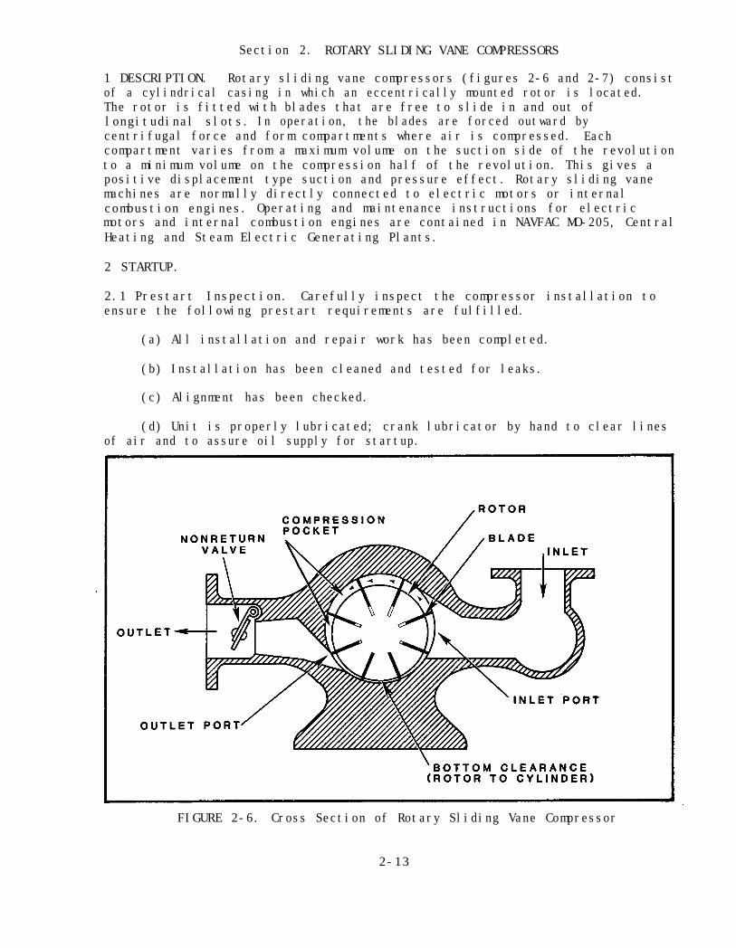
1 DESCRIPTION. Rotary sliding vane compressors (figures 2-6 and 2-7) consistof a cylindrical casing in which an eccentrically mounted rotor is located.The rotor is fitted with blades that are free to slide in and out oflongitudinal slots. In operation, the blades are forced outward bycentrifugal force and form compartments where air is compressed. Eachcompartment varies from a maximum volume on the suction side of the revolutionto a minimum volume on the compression half of the revolution. This gives apositive displacement type suction and pressure effect. Rotary sliding vanemachines are normally directly connected to electric motors or internalcombustion engines. Operating and maintenance instructions for electricmotors and internal combustion engines are contained in NAVFAC MO-205, CentralHeating and Steam Electric Generating Plants.
2 STARTUP.
2.1 Prestart Inspection. Carefully inspect the compressor installation toensure the following prestart requirements are fulfilled.
(a) All installation and repair work has been completed.
(b) Installation has been cleaned and tested for leaks.
(c) Alignment has been checked.
(d) Unit is properly lubricated; crank lubricator by hand to clear linesof air and to assure oil supply for startup.
FIGURE 2-6. Cross Section of Rotary Sliding Vane Compressor
2-13

FIGURE 2-7. Cutaway View of Two-Stage, Rotary Sliding Vane Compressor
2 - 1 4
(e) Compressor turns freely by hand.
(f) Direction of motor rotation is correct.
(g) Unloader operation has been checked.
(h) Safety valve operation has been checked.
2.2 Startup. Proceed as follows:
(a) Open discharge shutoff valve.
(b) Turn on cooling water supply. Thoroughly vent jackets andintercooler.
(c) Set regulating device to unloaded position.
(d) Start motor and bring unit up to speed.
(e) Check and adjust lubricator feed rate in accordance withmanufacturer's instructions.
(f) Load the compressor if machine is running smoothly.
3 NORMAL OPERATION. While the system is operating, perform the followingtasks.
(a) Maintain proper lubricating oil levels.
(b) Drain oil separator and receiver.
(c) Check automatic traps for proper operation.
(d) Check compressed air and cooling water pressures and temperaturesdaily.
4 SHUTDOWN. Proceed as follows:
(a) Unload compressor.
(b) Stop motor.
(c) Shut off cooling water supply.
(d) If the compressor is to be subjected to freezing temperatures,thoroughly drain cylinder jackets, coolers, and drain traps.
4.1 Extended Shutdown. Rotary sliding vane compressors should not be leftidle for long periods of time. Rust and corrosion will cause rapiddeterioration if the machine is not properly protected. Rotor bladeexpansion, caused by the absorption of moisture, is another potentialproblem. Observation of the following procedure should adequately provide theproper protection.
2-15
(a) Every 2 weeks, turn the compressor over by hand to distribute oil t othose areas requiring lubrication, then operate the compressor for a minimumof 2 hours. This will keep the interior dry, well lubricated, and preventabsorption of moisture by the blades.
(b) Do not allow cooling water to run after shutdown. This causesinternal condensation that can be absorbed by the blades.
(c) If the compressor is to be subjected to freezing temperatures,thoroughly drain cylinder jackets, coolers, and drain traps.
5 OPERATIONAL PREVENTIVE MAINTENANCE. Operational preventive maintenanceincludes the following tasks.
(a) Keep a daily log of compressed air and cooling water temperaturesand pressures, and lubricating oil additions to detect any deviations fromnormal operating values. On two-stage machines,low interstage pressureindicates a malfunction in the first stage or stoppage of the intake filter.High interstage pressure may indicate that the second stage is not operatingproperly or that the air from the first stage is not being cooled sufficientlyby the intercooler.
(b) Keep the machine clean at all times by wiping daily with a cloth.Dirt accumulations will eventually work their way into the machine and causeaccelerated wear.
(c) Do not operate a compressor beyond its rated capacity. Overloadoperation results in overheating and damage to running surfaces.
(d) Do not overtighten packing gland. This results in rapid packingwear and shaft scoring. Gland should be pulled up finger-tight and some oilleakage should be present.
(e) Check lubricator weekly for proper drop rate.
6 PREVENTIVE MAINTENANCE INSPECTION. The following inspection schedules areadequate for average installations.
6.1 Daily Inspection. The operator shall inspect the installation daily forthe following conditions:
(a) Unusual noise or vibration
(b) Abnormal pressures or temperatures
(c) Proper lubricating oil levels
(d) Abnormal stuffing box temperatures
(e) Abnormal bearing temperatures
(f) Overheating of motor
2-16

6.2 Quarterly Inspection. Inspect the compressor every 3 months for thefollowing conditions:
(a) Operation of all safety valves
(b) Proper operation of all controls
6.3 Semiannual Inspection. Inspect for the following conditions:
(a) Alignment of the compressor to the drive
(b) On two-stage units, alignment of the outboard compressor to theinboard one
(c) Condition of packing, if provided
6.4 Annual Inspection. Once a year or more often, depending on the severityof service, dismantle the compressor and inspect for the following conditions:
(a) Bearings for wear and dirt
(b) Shaft for wear at seals
(c) Mechanical seals for damage, if they are provided
(d) Rotor blades; remove and inspect for wear
(e) Wear and scoring of cylinder bore
(f) Damage to gaskets
7 MAINTENANCE.
7.1 Rotor Blades. Rotor blades should be replaced if the blade thickness atany point is less than 85 percent of the rotor slot width; if the blade widthis less than 90 percent of the rotor slot depth; or if there is any charring,splitting, or chipping on the running edge of the blades.
(a) Thoroughly clean the rotor slots when replacing or installing newblades.
(b) Thoroughly clean and oil blades before installation.
7.2 Cylinders. Thoroughly clean cylinder interior annually as follows:
(a) Blow out all oil holes ensuring they are open and free of sludge.
(b) Flush out cylinder jackets with a water hose to remove dirtaccumulations.
(c) Stone rough spots on cylinder walls, cylinder heads, and rotor.
2-17

(d) When reassembling, oil each part with clean lubricating oil.
(e) Replace defective gaskets.
7.3 Bearings. Replace worn or defective bearings as required. If bearingreplacement becomes necessary,heating it with a torch.
the inner race may be removed from the shaft by
not the shaft.Care must be taken to heat the inner race only and
The inner race is shrunk onto the shaft, so that heating bothparts will not free the bearing. Never attempt to pull the inner race off theshaft without heat, as damage to the shaft will result. To install a newinner race, it is necessary for it to be thoroughly heated in an oil bath to atemperature of 200°F to 300°F depending on manufacturer's instructions. Itwill then slip easily onto the shaft.
the bearings. Clearances must be closely held for proper operation of thecompressor. Clearances are normally given on the compressor nameplate.Follow the manufacturer's instructions carefully for setting clearances.
7.4 Clearances. Each time the compressor is inspected internally ordisassembled for repair, clearances must be checked. These include clearancesbetween the rotor and cylinder, the rotor ends and the cylinder heads, and in
7.5 Lubrication. Rotary sliding vane compressors are normally fitted withmechanical force-feed lubricators driven from the compressor shaft. On newcompressors,more oil than
or compressors that have been overhauled, feed about 25 percentnormal for about 2 weeks until the compressor has been run-in.
For normal operation, the feed should be adjusted to the drip rate indicatedon the lubricator nameplate.indicators.
Rate of flow can be observed in the sight flow
2-18

Section 3. ROTARY TWIN-LOBE COMPRESSORS
1 DESCRIPTION. Rotary twin-lobe compressors (blowers) consist of twoimpellers mounted on parallel shafts that rotate in opposite directions withina housing (figure 2-B). As the impellers rotate, they trap a quantity of airbetween themselves and the blower housing and move the air from the inlet tothe discharge port. The operating principle of this type compressor isunusual since the impellers do not compress the air while moving it. Instead,as each impeller uncovers the discharge port, the pressurized air in thedischarge line flows back into the compressor compressing the air between thedischarge port and the next lobe of the impeller. As the impellers turn, theyforce this pressurized air into the discharge line and immediately start a newcycle, as shown in figure 2-B. This action takes place four times perrevolution, twice for each impeller. The impellers are positioned in relationto each other by timing gears located at the end of each shaft and external tothe blower housing. Rotary twin-lobe compressors (figure 2-9) are normallyelectric motor driven through V-belts or by direct connection. Operating andmaintenance instructions for electric motors are contained in NAVFAC MO-205,Central Heating and Steam Electric Generating Plants.
2 STARTUP.
If impellers are to be rotated, keep hands, feet, loose clothing,and foreign objects away from inlet and discharge openings, asserious personal injury or damage to equipment can occur.
Do not operate equipment without adequate silencing devices. Highnoise levels may cause permanent hearing damage.
2.1 Prestart Inspection. Carefully inspect the compressor installation toensure the following prestart requirements are fulfilled.
(a) All installation and repair work has been completed.
(b) Installation has been cleaned and tested for leaks.
(c) Alignment has been checked.
(d) Compressor and drive have been properly lubricated.
(e) Operation of safety valves has been checked.
(f) Compressor discharge valves are open.
2.2 Startup. Proceed as follows:
(a) Turn compressor over by hand to see that it turns freely.
2-19

FIGURE 2-B. Impeller Arrangement of Rotary Twin-Lobe Compressor
FIGURE 2-9. Rotary Twin-Lobe Compressor
2-20

(b) Check motor for correct direction of rotation.
(c) Turn on cooling water to oil cooler, if provided.
(d) Start the compressor.
3 NORMAL OPERATION. While the system is operating, perform the followingtasks.
(a) Maintain correct oil levels.
(b) Check air discharge and lubricating oil pressures.
(c) Watch for irregular compressor performance and any unusual noise orvibration.
4 SHUTDOWN. When the compressor is to be out of service for an extendedperiod, coat the impellers and the inside of the housing with a heavy oil orgrease to prevent rusting and corrosion. Before returning the unit toservice, thoroughly clean all oil or grease from the compressor interior.
5 OPERATIONAL PREVENTIVE MAINTENANCE. Operational preventive maintenanceincludes the following tasks.
(a) Operate the compressor within the rated capacity, otherwiseoverheating of the compressor and drive may occur.
(b) On units fitted with oil coolers, ensure that the temperature of theoil to the gears and bearings is within the limits recommended by themanufacturer.
(c) Maintain oil levels within the limits indicated on the oil levelgauge. Insufficient oil will result in improper lubrication. Too much oilwill cause overheating of bearings and gears.
6 PREVENTIVE MAINTENANCE INSPECTION. The following inspection schedules areadequate for average installations.
6.1 Daily Inspection. The operator shall inspect the compressor daily forthe following conditions:
(a) Unusual noise or vibration
(b) Abnormal suction or discharge pressure or temperature
(c) Abnormal oil pressure when force-fed lubrication is provided
(d) Abnormal bearing temperatures
(e) Overheating of motor
(f) Oil leaks
2-21

6.2 Annual Inspection. Once a year or as required, depending on the severityof service, clean and inspect the compressor for the following conditions:
(a) Corrosion or erosion of parts
(b) Proper clearances
(c) Correct alignment
(d) Worn or broken timing gears
(e) Timing gear setting
(f) Operation and setting of safety valves
(g) Wear of shafts at seals
7 MAINTENANCE.
7.1 Lubrication. Establish a definite lubrication schedule for thecompressor, and establish specific responsibilities for carrying out periodiclubrication. Frequency of lubrication and type of lubricant should be asrecommended by the manufacturer.
7.2 Timing Gears. Timing gears maintain the compressor impellers in properrotative position and hold impeller clearances. They must be securely lockedto their shafts in proper position. Gears or impellers that have been removedfor repair must be returned to their original positions. When installing newor repaired parts, carefully follow the manufacturers' instructions forsetting clearances. Clearances must be set accurately or damage to themachine may result from impeller rubbing.
7.3 Seals. Rotary twin-lobe compressors are normally fitted with mechanicalseals. Seals should be kept free of dirt, dust, and foreign matter to ensurelong life. Sealing faces are lapped together during manufacture and theentire assembly must be replaced when defective seals are found. Use extremecare when installing seals to prevent marring of the sealing faces. Be surethat the lapped sealing faces are free of scratches, dust, or finger marksbefore installation. Carefully follow the manufacturers' instructions whenreplacing mechanical seals.
7.4 Bearings. Rotary twin-lobe compressors are normally fitted withantifriction ball or roller bearings. Worn or defective bearings should bereplaced. Wear to bearings may allow the impeller shaft to shift positionuntil a cylinder rub develops or the impellers begin rubbing. Carefullyfollow the manufacturers' instructions when replacing bearings.
2-22

Section 4. ROTARY LIQUID PISTON COMPRESSORS
1 DESCRIPTION. Rotary liquid piston compressors (figures 2-10 and 2-11)utilize a liquid (water or other low viscosity liquid) as the compressant.The unit consists of a round multiblade rotor that rotates in an ellipticalcasing partially filled with liquid. The liquid is carried around by therotor and follows the contour of the casing. The rotor buckets are filledwith air, through the intake port, by the suction created when the liquid isforced to recede from the rotor buckets at the wide point of the ellipticalcasing. As the liquid reaches the narrow point of the ellipse, it reentersthe buckets, compresses the air, and passes it out through the dischargeports. The cycle is repeated twice for each revolution of the rotor. Liquidis supplied continuously to the compressor to take up the heat ofcompression. Excess water is discharged from the compressor with the air andis removed by a separator connected to the compressor discharge. Operatingand maintenance instructions for electric motor drives are contained in NAVFACMO-205, Central Heating and Steam Electric Generating Plants.
2 STARTUP.
2.1 Prestart Inspection. Carefully inspect the installation to ensure thefollowing prestart requirements are fulfilled.
(a) All installation and repair work has been completed.
(b) Installation has been cleaned and tested for leaks.
(c) Alignment has been checked.
(d) Safety valve has been tested for proper operation.
(e) Compressor is properly lubricated.
2.2 Startup. Proceed as follows:
(a) Open compressor discharge valves.
(b) Turn on compressor sealing-water.
(c) Start the compressor.
3 NORMAL OPERATION. While the system is operating, perform the followingtasks.
(a) Maintain correct sealing-water flow rate.
(b) Check air discharge pressures.
(c) Watch for irregular performance of the compressor.
4 SHUTDOWN. When removing the compressor from service for an extendedperiod, thoroughly drain the casing of all sealing-water. Run a flushing oilthrough the compressor to prevent rusting and corrosion. Repack greaselubricated bearings with new grease and fill oil lubricated bearings with
2-23

Starting at point A, the chambers of the rotor are filled withwater. This water rotates with the rotor, but follows the contourof the casing. The water, which entirely fills the rotor chamberat point A, recedes into the casing as the rotor advances, untilat point C, the rotor chamber is empty. The converging casingforces the water back into the rotor chamber, until at point D,the chamber is again full. This cycle occurs once during eachrevolution of the rotor. As water recedes from the rotor chamberat point B, the water is replaced by air drawn through an inletport in the stationary conical casing that connects to thecompressor inlet. As the rotor turns through 360° and water isforced by the casing back into the rotor chamber, the air that hasfilled the chamber is forced through discharge ports in theconical casing to the compressor discharge. The water used as theliquid compressant also serves to seal clearances between therotor and the cone and is referred to as seal water.
FIGURE 2-10. Compression Cycle, Rotary Liquid Piston Compressor
2-24

FIGURE 2-11. Functional Elements, Rotary Liquid Piston Compressor
fresh oil. Remove shaft packing. Turn the compressor over by hand once aweek to keep a coating of oil on the bearings.
5 OPERATIONAL PREVENTIVE MAINTENANCE. Operational preventive maintenanceshall include the following tasks.
(a) Never run a liquid piston compressor dry. Operation withoutsealing-water results in serious damage to the compressor.
(b) Maintain correct sealing-water flow rate. Insufficient sealing-waterwill result in a loss of capacity. Excess sealing-water overloads thecompressor drive. Consult the manufacturer's instructions for correctsealing-water quantities.
(c) Do not overtighten the packing on units with stuffing boxes. Thisresults in rapid packing wear and scoring of the shaft.
6 PREVENTIVE MAINTENANCE INSPECTION. The following inspection schedules areadequate for average installations.
6.1 Daily Inspection. The operator shall inspect the compressor installationdaily for the following conditions:
(a) Unusual noise or vibration
(b) Abnormal discharge pressures
(c) Overheating of motor
2-25
(d) Abnormal bearing temperatures
(e) Correct sealing-water flow and pressure
6.2 Semiannual Inspection. Inspect the following items:
(a) Alignments
(b) Wear of packing and scoring of shaft at packing or seals
(c) Setting and operation of safety valves
6.3 Annual Inspection. Once a year or as required, depending upon theseverity of service, inspect for the following conditions:
(a) Bearings for wear and dirt
(b) Corrosion or erosion of parts
(c) Correct clearances
(d) Compressor internals for scale deposits
(e) Gaskets for damage
(f) Mechanical seals, if provided, for damage
7 MAINTENANCE.
7.1 Lubrication. Establish a definite lubrication schedule, in accordancewith the manufacturer's recommendations, for all liquid piston compressors.Assign responsibilities for carrying out the lubrication schedule. Follow themanufacturer's recommendations for the types of lubricants to be used.
7.2 Packing. When replacing fibrous packing, thoroughly clean the stuffingbox of old packing and grease. Cover each piece of new packing with therecommended lubricant. Separate the new rings at the split joint to placethem over the shaft. Place one ring of packing at a time in the stuffing boxand tamp firmly in place. Stagger the joints of each ring so they are not inline. After the last ring is in place, assemble the gland and tighten thenuts evenly until snug. After a few minutes, loosen the nuts and retightenthem finger-tight.
7.3 Bearings. Worn or defective bearings should be replaced. Bearings aremounted in brackets on each end of the housing and are attached to the rotorshaft by locknuts. When bearings are replaced on belt-driven units,carefully check and set the belt tension. Keep the belt as loose as possiblewithout slippage. Excessive belt tightening will put an unnecessary strain onthe compressor bearings. When mounting pulleys or couplings that require adrive fit on the compressor shaft, back up the opposite end of the shaft toabsorb the driving force. Unless this is done, there is danger of damagingthe bearings. Maintenance instructions for antifriction ball and rollerbearings are contained in NAVFAC MO-205, Central Heating and Steam ElectricGenerating Plants.
2-26
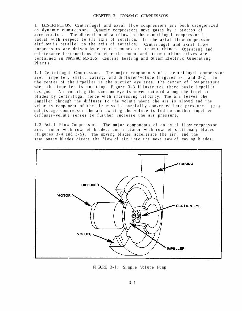
CHAPTER 3. DYNAMIC COMPRESSORS
1 DESCRIPTION. Centrifugal and axial flow compressors are both categorizedas dynamic compressors. Dynamic compressors move gases by a process ofacceleration. The direction of airflow in the centrifugal compressor isradial with respect to the axis of rotation. In the axial flow compressorairflow is parallel to the axis of rotation. Centrifugal and axial flowcompressors are driven by electric motors or steam turbines. Operating andmaintenance instructions for electric motor and steam turbine drives arecontained in NAVFAC MO-205, Central Heating and Steam Electric GeneratingPlants.
1.1 Centrifugal Compressor. The major components of a centrifugal compressorare: impeller, shaft, casing, and diffuser/volute (figures 3-l and 3-2). Inthe center of the impeller is the suction eye area, the center of low pressurewhen the impeller is rotating. Figure 3-3 illustrates three basic impellerdesigns. Air entering the suction eye is moved outward along the impellerblades by centrifugal force with increasing velocity. The air leaves theimpeller through the diffuser to the volute where the air is slowed and thevelocity component of the air mass is partially converted into pressure. In amultistage compressor the air exiting the volute is fed to another impeller-diffuser-volute series to further increase the air pressure.
1.2 Axial Flow Compressor. The major components of an axial flow compressorare: rotor with rows of blades, and a stator with rows of stationary blades(figures 3-4 and 3-5). The moving blades accelerate the air, and thestationary blades direct the flow of air into the next row of moving blades.
FIGURE 3-l. Simple Volute Pump
3-1

FIGURE 3-2. Six-Stage Compressor
FIGURE 3-3.Impeller Design
3-2

This sequence continues until the air has passed through all the rows ofmoving blades. The stationary blades also offer a small amount of flowresistance, which slows down the air and increases its pressure. In an axialflow compressor, it is the continual process of accelerating the air and thenslowing it down that builds up the air pressure.
2 STARTUP.
2.1 Prestart Inspection. Carefully inspect the compressor installation,performing the following prestart tasks.
Compressor equipment, compressed air, and electricity can bedangerous. To prevent injury, before attempting any maintenance becertain the compressor cannot be started accidentally.
(a) Ensure power switch is in OFF position and tag, or verify that powershutoff valve is in OFF position and tag.
(b) Verify completion of all installation or repair work.
(c) Ensure installation has been cleaned.
(d) Verify that system has been tested for leaks.
FIGURE 3-4. Axial Flow Compressor
3-3

FIGURE 3-5. Rotor and Stator Blades, Axial Compressor
(e) Check coupling alignment (refer to paragraph 7.2).
(f) Check lubricating oil levels and top off, if required.
(g) Check all safety devices and controls for proper operation.
(h) Turn compressor over by hand to see that it rotates freely.
(i) Open all compressor, drain valves, drain off all liquid, and closedrain valves.
2.2 Startup Procedure. Proceed as follows:
Protective devices must be worn to avoid damage to hearing.
(a) Remove tag from electric power switch and switch to ON position, orremove tag from power shutoff valve and turn to ON position.
(b) Turn on cooling water.
(c) Start oil pump and check oil pressure.
(d) Turn on sealing air to seals, if provided.
(e) Open suction and discharge valves.
3-4

Never operate compressor in the critical speed range (insufficientvolume at the compressor inlet to permit stable operation); surgingor pumping will occur. Operation under these conditions may resultin equipment damage.
(f) Start compressor drive motor as follows, depending on type:
(1) Single Speed Motor. Start and stop the motor quickly and allowthe compressor to coast to a stop. Check for freedom of rotation and anyunusual noise or vibration. If unit runs smoothly, start the motor and bringup to speed.
(2) Variable Speed Motor. Start the motor and bring it slowly upto speed, observing the operation carefully for unusual noise or vibration.
3 NORMAL OPERATION. While the system is operating, perform the followingtasks.
(a) Check and record operational data at prescribed intervals(paragraph 5).
(b) Watch for irregular performance of the compressor and drive.
(c) Maintain proper lubricating oil levels.
4 SHUTDOWN.
4.1 Short-Term Shutdown. Proceed as follows:
To avoid damage to equipment, after shutting down the drive, keepauxiliary lubricating oil pump operating until bearings have cooledto ambient temperatures.
(a) Shut down compressor drive.
(b) Close suction and discharge valves.
(c) Shut off cooling water supply.
(d) Shut off seal air, if provided.
(e) Open compressor drain valves and drain off any liquid present.
(f) Shut off lube oil pump after bearings have cooled to ambienttemperature.
3-5
4.2 Long-Term Shutdown. Long-term shutdown procedures require extensivedisassembly. Consult the manufacturer for complete details for specificcompressors. In the absence of specific procedures, use the followingprocedures where applicable.
(a) Centrifugal Compressors. Proceed as follows:
(1) Shutdown system as described in paragraph 4.1.
(2) Open the compressor case, remove intercoolers, diffusers,diffuser covers,rotors, bearings, and drain traps.
(3) Remove the plain and thrust bearings.
(4) Blow dry air through the water manifolds, including the oilcoolers. Spread vapor phase inhibitor (VPI) crystals in the cooling watermanifolds.
(5) Identify each rotor and impeller if applicable. Coat each rotorcomponent with a rust inhibitor and pack securely in a carton.
(6) Wipe and dry all unprotected internal machined surfaces. Coatall surfaces with a rust inhibitor, including diffuser and intercooler bores.
(7) Thoroughly dry the intercoolers and reinstall them.
(8) Reinstall diffuser covers, diffusers, and intercoolers.Distribute VPI crystals throughout and close the machine.
(9) All openings must be adequately sealed with gasketed flanges,plugs, or poly wraps to prevent loss of VPI vapors, including the seal aircasing vents and drains.
(10) Remove the reservoir breather and seal the opening. Coat theexposed portion of the shaft and coupling hub with preservative.
(11) Remove inlet and bypass control valves and the check valve.Clean, dry, and box.
(12) Remove all probes and cables and box adequately.
(13) Replace thrust bearing and covers and close up ALL openingsusing pipe plugs or blank flanges with gasket.
(14) Seal the bottom of the control cabinet if it is of the opendesign.
(15) Coat main drive coupling spacer with preservative and pack inseparate box.
(16) Coat all external machined unpainted surfaces with preservative.
3-6
(b) Axial Flow Compressors. It is important to implement properlong-term storage (LTS) procedures according to the specific model ofcompressor. In situations where LTS is planned, the manufacturer must becontacted to provide LTS procedures. In most instances, LTS will includespecific variations of the following:
(1) Partial disassembly
(2) Periodic rotation of main shaft
(3) Use of desiccants
(4) Specialized bearing maintenance according to bearing types
(5) Proper tagging
4.3 Cold Climate Shutdown. If the compressor might be subjected to freezingtemperatures while shut down, perform the following steps as applicable.
(a) Perform steps 4.1(a) through 4.1(f).
(b) Drain water from oil cooler.
(c) Drain all steam lines.
(d) Drain all cooling lines.
(e) Drain water-cooled diaphragms.
(f) Tag equipment controls.
5 OPERATIONAL PREVENTIVE MAINTENANCE. Operational preventive maintenanceincludes the following tasks.
(a) Keep a daily operating log to aid in detecting equipmentmalfunctions. The following list may be helpful in designing a site specificoperations log for collecting and developing a useful data base:
(1) Log-in time
(2) Vibration monitor reading at each compressor stage
(3) Warning lights
(4) Inlet temperature
(5) Inlet filter pressure
(6) Pressure and temperature of each compressor stage
(7) Condition of condensate trap at each compressor stage
(8) Air coolers temperature in and out
3-7

(9) Oil pressure
(10) Oil cooler temperature in and out
(11) Oil level at motor
(12) Oil level at oil reservoir
(13) Drain drip legs
(14) Hours on unit
(15) Bearing temperatures
(16) Compressor speed
(b) Wipe down machine daily with clean, lint-free rag.
6 PREVENTIVE MAINTENANCE INSPECTION. An inspection and maintenance programis important to ensure satisfactory performance. One of the most importantaspects of any maintenance program is prudent use of the operational data basecompiled from a daily operating log [paragraph 5(a)]. An operational logprovides an indication of performance, need for revising the maintenanceschedule, and, indirectly, spare parts requirements. Generalized proceduresare presented herein, but frequency of inspections will vary and must reflecteach installation's operating conditions and environment.
6.1 Daily Inspection. Preventive maintenance inspections shall include thefollowing tasks.
(a) Review the current operating log for significant deviations in thedata such as:
(1) Abnormal pressures or temperatures of lubricating oil
(2) Abnormal appearance or presence of water in lubricating oil
(3) Lubricating oil levels
(4) Abnormal bearing temperatures
(5) Increased inlet filter pressure
(b) Listen for unusual noises.
(c) Listen and feel for unusual vibrations.
(d) Visually inspect the complete compressor plant for leaking fittingsor loose fasteners.
6.2 Semiannual Inspection. In addition to performing inspections specifiedin paragraph 6.1, perform the following tasks.
(a) Check lubricating oil for deterioration and/or presence of water.
3-8

(b) Test safety controls to ensure proper functioning.
6.3 Annual Inspection. In addition to performing inspections specified inparagraphs 6.1 and 6.2, perform the following procedures where applicable.
(a) Check journal and thrust bearings for wear. Adjust or replace asrequired.
(b) Check alignment and coupling condition. Visually inspect couplingcondition and use dial indicator to realign coupling within specifiedtolerances (paragraph 7.2).
(c) Clean and repaint all areas of corrosion or peeling paint oncompressor case.
(d) Check compressor bolts for tightness. Retighten loose bolts tospecified torque values.
6.4 Internal Inspection. If compressor performance has fallen off, or noiseor driver overload indicate internal trouble, dismantle the compressor andmake the following inspection.
(a) Examine casing or stator for corrosion or erosion damage and dirt.
(b) Check case for water leaks if diaphragm cooling is provided.
(c) Inspect rotor for corrosion or erosion damage to impellers or blades.
(d) Check rotor for balance.
(e) Check clearances and condition of rotor, bearings, and seals.Record all measurements. If the need for bearing replacement is indicated,refer to paragraph 7.3.
(f) Perform lubrication system maintenance (paragraph 7.1).
7 MAINTENANCE.
7.1 Lubrication System. Lubrication system maintenance must be performed atintervals prescribed for each specific installation. In addition, lubricationsystem maintenance shall be performed at times of internal inspection andrepair. Lubrication system maintenance includes the following tasks.
(a) Clean oil filters and strainers or replace cartridges.
(b) Change oil if it is warranted by a chemical analysis or periodicschedule. To change oil perform the following tasks.
(1) Tag equipment controls.
(2) Drain oil from all systems.
3-9
To avoid internal damage to equipment, use only synthetic spongeswhen cleaning internal surfaces and components. Do not use clothrags or cotton waste.
(3) Thoroughly clean bearing chambers and oil reservoirs.
Do not use gasoline, kerosene, or other low flashpoint solvents. Aserious explosion may result.
(4) Flush out complete lubricating system with flushing oil.
(5) Inspect oil pumps for corrosion, erosion, and wear.
(6) Remove tube bundles from oil coolers, if applicable, andthoroughly clean tubes.
(7) Ensure closure of all drain valves, reinstallation of plugs,and reinstallation of sump covers.
(8) Refill lubricating oil reservoirs to proper level.
(9) Remove tag from controls.
(10) Follow procedures for startup provided in paragraph 2.2.
7.2 Alignment. Alignment of the unit may be checked with a dial indicator.Refer to specific installation manual for applicable tolerances. To align thecoupling, perform the following procedure.
To ensure proper alignment, check alignment in both the hot and coldcondition. After checking the alignment in the cold condition,operate the compressor under full load for 1 hour. Shut down theunit and recheck the alignment immediately.
NOTE
When using the dial indicator, make sure the compressor shaft endplay is held constant in one direction.
(a) Attach indicator bracket to compressor hub of coupling. Figure 3-6illustrates two methods of attaching the indicator mounting bracket to thecoupling.
3-10

(b) Attach dial indicator to mounting bracket with the pointercontacting the shoulder on the coupling hub.
(c) Rotate compressor shaft and take readings 90° apart.
(d) Correct axial misalignment by adding or removing shims under thedriver to bring compressor and drive centerlines into alignment.
(e) To check angular alignment, follow the above procedure, but takeindicator readings on the coupling hub face (figures 3-6 and 3-7).
(f) To correct angular misalignment, parallel the coupling faces byshifting the drive on its base and adding or removing shims under the driverbase.
7.3 Bearings. Centrifugal and axial flow compressors utilize many bearingtypes such as: split sleeve, steel backed babbit inserts, tilting pad, andantifriction roller and ball bearings. Use specific manufacturer'sinformation for bearing wear, adjustment, and replacement considerations.
FIGURE 3-6. Alignment Setup
3-11
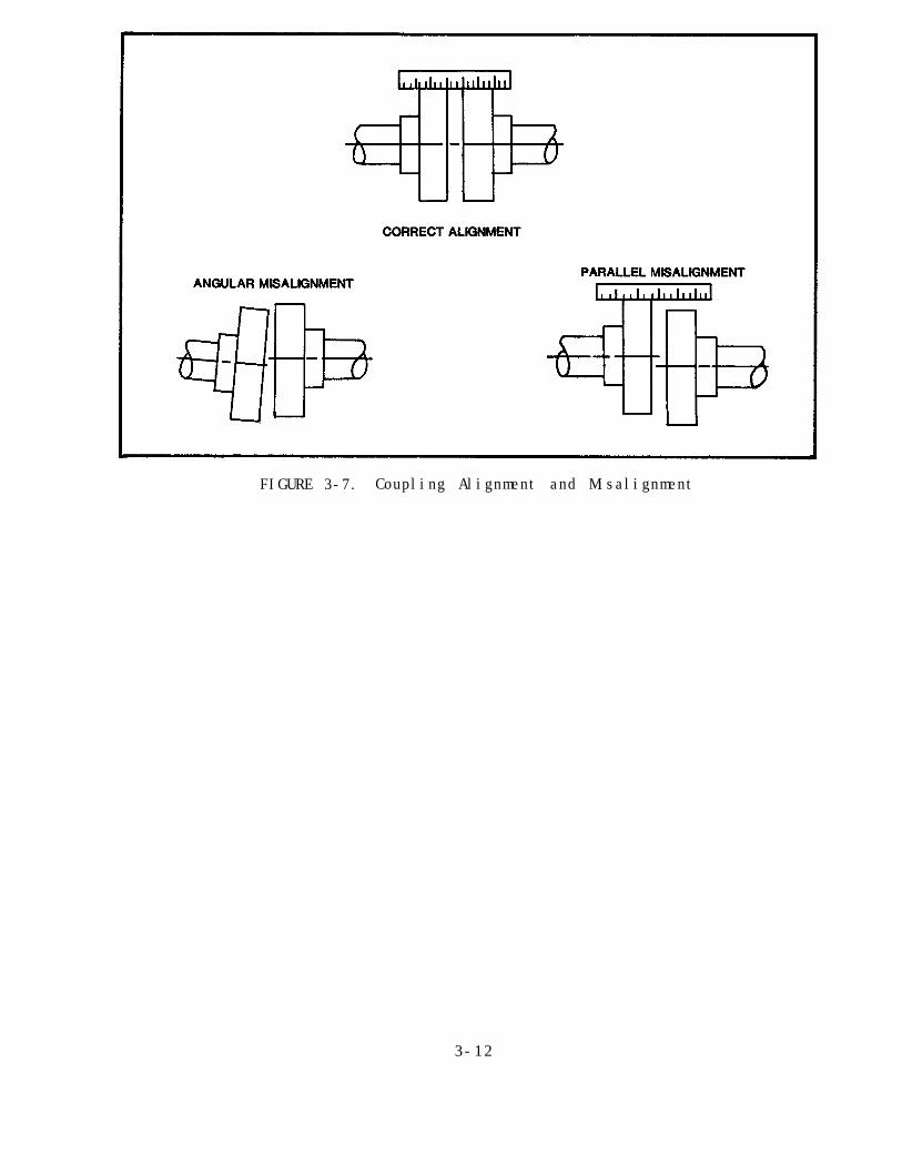
FIGURE 3-7. Coupling Alignment and Misalignment
3-12
CHAPTER 4. AUXILIARY EQUIPMENT
Section 1. INTAKE FILTERS
1 DESCRIPTION. Air filters are provided on air compressor intakes to preventatmospheric dust from entering the compressor and causing scoring andexcessive wear. There are two types of air filters, the dry type and theoil-wetted type. Generally, dry type filters are more efficient thanoil-wetted types in trapping and removing very fine, solid particles from theincoming air. However, dry type filters must be cleaned and replaced moreoften than oil-wetted types. Oil-wetted types are often used where there areheavy dust concentrations present in the atmosphere.
1.1 Dry Type Filter. Dry filters employ many different materials for thefilter media. Paper, polyester felt, and fine wire mesh are a few examples.The filter media can be folded, wrapped, and layered in many configurations toachieve the desired efficiency. Although the dry filter is more efficientthan the wetted type filter, the pores in the dry filter media become cloggedand result in a pressure drop across the filter. Dry type filters cannot beused successfully where intake air contains moisture or vapors in amounts thatwould cause disintegration of the filtering media. The main advantages of thedry type filter, when used in an approved application, is its high efficiencyand ease of maintenance.
1.2 Oil-Wetted Type Filter. Wet filters have filter elements that are coatedwith a film of oil. The oil film catches airborne particulates before theyreach the actual filter element media. Wetted type filters are of twodesigns, oil-wetted and oil-bath filters. In an oil-wetted filter, a coatingof oil is deposited on the filter element, which is usually made of layers ofwire mesh. The oil coating is intended to adhere to the element for a fairlylong service period. The airborne particulates are impinged or trapped on thefilter element which has been covered with a film of oil. In an oil-bathfilter (figure 4-l), the same viscous impingement principle is employed.However, the airflow is directed through the oil sump, carrying oil with it tothe filter element where the oil collects and washes the impinged particlesdown to the oil sump, forming sludge. The self-washing aspect of the oil-bathfilter extends the time between maintenance routines.
2 INSPECTION. Air filter inspections are to be performed when any of thefollowing conditions exist.
(a) Prescribed time interval on the maintenance schedule has elapsed.
(b) Pressure drop across the filter element indicates a maintenancerequirement.
(c) One-fourth inch of sludge has built up in the oil sump of theoil-bath type filter.
4-l
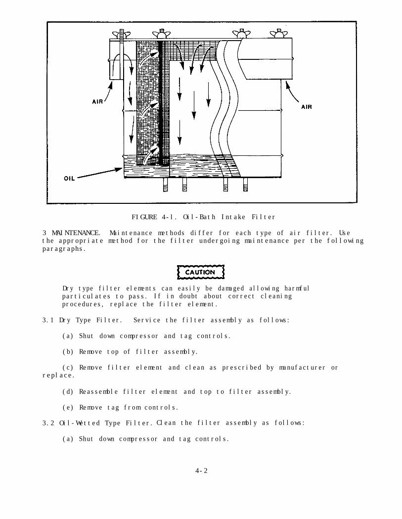
FIGURE 4-l. Oil-Bath Intake Filter
3 MAINTENANCE. Maintenance methods differ for each type of air filter. Usethe appropriate method for the filter undergoing maintenance per the followingparagraphs.
Dry type filter elements can easily be damaged allowing harmfulparticulates to pass. If in doubt about correct cleaningprocedures, replace the filter element.
3.1 Dry Type Filter. Service the filter assembly as follows:
(a) Shut down compressor and tag controls.
(b) Remove top of filter assembly.
(c) Remove filter element and clean as prescribed by manufacturer orreplace.
(d) Reassemble filter element and top to filter assembly.
(e) Remove tag from controls.
3.2 Oil-Wetted Type Filter. Clean the filter assembly as follows:
(a) Shut down compressor and tag controls.
4-2
(b) Remove the top and filter element from filter assembly.
Do not use gasoline, kerosene, or other low flashpoint solvents. Aserious explosion may result.
(c) Wash filter element with approved solvent or detergent and watersolution.
(d) Dry filter element thoroughly.
(e) Apply fresh oil by spray or dip and let excess oil drain. Use oiltype suggested by manufacturer.
(f) Clean filter body.
(g) Reinstall filter element and top to filter assembly.
(h) Remove tag from controls.
3.3 Oil-Bath Filter. Clean the filter assembly as follows:
(a) Shut down compressor and tag controls.
(b) Remove filter assembly from compressor.
Do not use gasoline, kerosene, or other low flashpoint solvents. Aserious explosion may result.
(c) Wash filter element with approved solvent or detergent and watersolution.
(d) Dry filter element thoroughly.
(e) Clean and dry filter oil sump.
(f) Add oil to oil sump to indicated level.
(g) Reinstall filter element and top on filter assembly.
(h) Reinstall filter assembly on compressor.
(i) Remove tag from controls.
4-3

INTENTIONALLY LEFT BLANK
4-4

Section 2. SILENCERS
1 DESCRIPTION. Compressor system silencers are sound-absorbing accessoriesattached to the system at the intake and output of the compressor. Thesilencers absorb noise produced by the compressor in order to reduce the noiseoutput to an acceptable level. In general, air noise silencers arecylindrical housings containing acoustically tuned baffles and sound-absorbingmaterial (figure 4-2).
2 INSPECTION AND MAINTENANCE. At intervals prescribed by the manufacturer'smaintenance schedule, inspect and perform maintenance on the silencer asfollows:
(a) Shut down system and tag controls.
(b) Inspect internal parts for damage or loosening from corrosion orvibration.
(c) Inspect interior of silencer and, if dirt is present, clean asfollows:
(1) Remove silencer from intake system and look for sources of dirtentry into silencer.
FIGURE 4-2. Compressor Intake Silencer
4-5

Do not use gasoline,kerosene, or other low flashpoint solvents. Aserious explosion may result.
(2) Clean silencer using approved solvent or detergent and watersolution.
(3) Dry silencer thoroughly.
Ensure all joints are tight to avoid entry of unfiltered air. Dirtin the air will cause premature wear to the compressor.
(4) Reinstall silencer into compressor system using new gaskets andseals.
(d) Check all external surfaces for corrosion, peeling, or damagedpaint. Repaint as necessary.
(e) Remove tag from controls.
4-6

Section 3. INTERCOOLERS AND AFTERCOOLERS
1 DESCRIPTION. Intercoolers and aftercoolers are heat exchangers employed todissipate the heat generated in compression. There are two types of heatexchangers used on air compressors, air-cooled and water-cooled.
1.1 Air-Cooled Heat Exchanger. Air-cooled heat exchangers are most oftenused on small compressors. The air-cooled heat exchanger is a finned, tubularradiator (figure 4-3).
1.2 Water-Cooled Heat Exchanger. The most common design of water-cooled heatexchangers, shell and tube type, consists of a single bundle of tubes enclosedinside a cylindrical shell (figure 4-4). The air to be cooled passes throughthe tubes while the water passes over the tubes. Baffles are often providedin the tube bundle to direct the waterflow across the heat exchanger tubes inthe most efficient manner.
(a) The intercooler is located between the discharge of one cylinder andthe intake of the next cylinder of multistage compressors. The intercoolerreduces the temperature and the volume of the compressed air for delivery tothe next compression stage.
(b) The aftercooler is located at the discharge of the last cylinder tocool the air, reduce its volume, and to liquify any condensable vapors.
FIGURE 4-3. Air-Cooled Heat Exchanger
4-7

FIGURE 4-4. Water-Cooled Heat Exchanger
2 STARTUP.
2.1 Prestart Inspection. Carefully inspect the intercooler or aftercooler,ensuring the following prestart requirements have been fulfilled.
(a) Verify completion of all installation or repair work.
(b) Ensure equipment has been cleaned and tested for leaks.
(c) Ensure thermometers, pressure gauges, and controls are in goodoperating condition.
(d) Ensure safety valves are operating.
2.2 Startup Procedure.waterflow before starting the air compressor. Proceed as follows:
Always start intercooler and aftercooler cooling
(a) Open air vent valves on waterside of cooler.
(b) Open cooling water inlet and outlet valves.
(c) Close waterside vent valves after all air has been displaced.
3 NORMAL OPERATION. Maintain rated cooling waterflow. Check airside drainperiodically to see that it is operating properly and unit is free ofcondensate.
4-8
4 SHUTDOWN. If the compressor is going to be shut down, perform thefollowing procedures.
(a) Maintain cooling waterflow until coolers have reached ambienttemperature.
(b) Drain all water from cooling system if the cooler will be exposed tofreezing temperatures.
5 OPERATIONAL PREVENTIVE MAINTENANCE. Observe the following proceduresduring normal operation.
(a) Maintain rated cooling waterflow. Avoid excessive waterflow whichmight cause erosion.
(b) Adjust waterflow rates slowly to avoid sudden temperature changes inthe cooler.
(c) Shut down compressor if condensate trap is collecting excessiveamounts of water. Cooler tubes may be leaking.
(d) Shut down compressor if cooler air temperature is abnormally high.Leak in cooler tubes could be allowing air to displace cooling water inwaterside of cooler.
6 PREVENTIVE MAINTENANCE INSPECTION.
6.1 Daily Inspection. Inspect the cooler daily for the following conditions:
(a) Proper operation of the automatic controls and instruments
(b) Water leaks, temperature, and flow rate
(c) Any deviations from normal temperature or pressure drops across thecooler
6.2 Periodic Inspection. Inspect the following items at intervals prescribedby the manufacturer's maintenance schedule.
(a) Check cooler for corrosion and peeling paint.
Do not attempt to repair or remove any compressor system partswithout first relieving pressure from the entire system.
(b) Check safety valves for setting and proper operation.
(c) Check manual and automatic valves for leakage and corrosion.
4-9

(d) Remove the tube bundle from the cooler and carefully inspect theinternals of the unit for the following conditions.
(1) Corrosion to tubes, tube sheets, and baffles: Corrosion andelectrolysis (galvanic corrosion) may appear very similar, but they aredifferent and occur because of the presence of entirely different elements.Since carbon dioxide and oxygen are the main causes of corrosion, anyoperating method that reduces the content of carbon dioxide and/or oxygen willreduce corrosive effects. One method to control CO2,and 02 levels in thecoolant is to reduce coolant losses wherever possible. This reduces the entryof additional free CO2 and 02 present in most makeup water.Differentpretreatments of makeup water may be required such as: lime soda softening,hot lime zeolite softening,acid cycle softening, and salt splitting. Alltypes reduce the quantity of CO2. Internally, corrosion of piping can becontrolled by the use of corrosion inhibitors.For more information, refer toNAVFAC MO-225, Industrial Water Treatment.
(2) Electrolysis of tubes, tube sheets, and baffles: Electrolysisis an electrochemical corrosion associated with the current caused bydissimilar metals in an electrolyte (coolant). It resembles erosion inappearance, but the loss of material is due to the exposure of two metals ofdifferent compositions (such as steel and bronze or steel and aluminum) to anelectrolyte (coolant).Two methods used for controlling the effects ofelectrolysis are electronic cathodic systems and sacrificial anode placementwithin the system (such as zinc compound plugs).
(3) Erosion to tubes, tube sheets, and baffles: Erosion may beevident at material edges, tube ends, and baffles, due to excessive flow ratesand coolant impurities. Evidence of erosion is rounded edges or depressionsin material surfaces at locations where the flow changes direction or rate.
(4) Leaking tubes: Any leaks in the cooler between the tubescarrying coolant and the tubes carrying compressed air is detrimental to thesystem. If a leak is found during a disassembly inspection it should berepaired before reassembly. In many instances when the water pressure isgreater than the air pressure, the first indication of a leak is the suddenincrease of moisture at the separator or receiver. If the air pressure ishigher than the water pressure, air then enters the coolant system resultingin higher temperatures.
(5) Plugged tubes: If tubes become plugged, it is an indication ofan imbalance in the coolant-equipment relationship and conditioning of thecoolant should be considered. Plugged tubes, depending on the number, usuallyresult in higher system temperatures. Most plugged tubes can be cleanedwithout causing damage to the tube. Consult the manufacturer's instructionsfor details.
(6) Scale deposits: Scale deposits are an indication of animbalance between the coolant-equipment relationship. Conditioning of thecoolant should be considered. Scale results in higher system temperatures.Refer to the manufacturer's instructions for correctional procedures.
4-10

7 MAINTENANCE.
Never hammer on the tubes or use sharp edged scrapers which maydamage the tubes.
Chemical solutions used for cleaning should be capable of dissolvingthe scale or other deposits without attacking the metal.
7.1 Cleaning. Tube interiors may be cleaned by flushing a stream of waterthrough them. For more persistent deposits,tools may be required.
brushes, rods, or other cleaning
hot water.Tube exteriors can be cleaned by hosing with steam or
A stiff bristle brush will aid in removing deposits from betweentubes. Cooler interiors may be cleaned without dismantling the unit bycirculating a chemical solution through it. All chemicals should bethoroughly washed out of the cooler before returning it to service.
7.2 Tube Replacement and Repair. Coolers with leaking tubes must be repairedin accordance with manufacturers' recommendations. Refer to specificmanufacturer's service manual for tube repair and replacement instructions.
4-11

4-12

Section 4. SEPARATORS
1 DESCRIPTION. Separators are used on compressor installations to removeentrained water and oil from the compressed air. Figure 4-5 shows acentrifugal type moisture separator where air is directed into the unit sothat it obtains a swirling motion. Centrifugal action forces the moistureparticles against the wall of the separator where they drain to the bottom.In the baffle type separator (figure 4-6) the air is subjected to a series ofsudden changes in direction. The heavier moisture particles strike thebaffles and walls of the separator and drain to the bottom of the unit.
2 OPERATION. Drain separators regularly if automatic drainers are notprovided. Frequency of draining is best determined by experience with theinstallation. Improperly drained separators result in moisture carryover intothe air distribution system.
3 PREVENTIVE MAINTENANCE INSPECTION. Inspect the separator at periodicmaintenance intervals for the following conditions:
(a) Externally for rust,corrosion and peeling paint
(b) Internally for corrosion and accumulations of dirt and oil
(c) Gaskets for damage
FIGURE 4-5. Centrifugal Type Separator
4-13

FIGURE 4-6. Baffle Type Separator
4 MAINTENANCE. Perform the following maintenance tasks.
Do not attempt to repair or remove any compressor system partswithout first relieving pressure from the entire system.
(a) Remove corrosion and peeling paint.
(b) Prime and paint prepared surfaces.
(c) Thoroughly clean separator internals.
(d) Replace defective gaskets.
4-14

Section 5. TRAPS
1 DESCRIPTION. Traps drain condensed moisture from intercoolers,aftercoolers, receivers, and distribution piping. The most common traps arethe ball float trap, bucket trap, and inverted bucket trap (figure 4-7). Anin depth discussion of traps is found in NAVFAC MO-209, Maintenance of Steam,Hot Water, and Compressed Air Distribution Systems.
2 STARTUP. Some compressed air drain traps must be primed before placingthem in service. This is done by filling the trap half full with freshwater.
3 SHUTDOWN. If the compressed air system is not in operation and the draintraps might be subjected to freezing temperatures, thoroughly drain the trapsof all condensate to prevent damage from freezing.
4 PREVENTIVE MAINTENANCE INSPECTION.
4.1 Daily Inspection. Check the operation of drain traps daily. Make surethe trap is draining properly and not blowing air.
4.2 Periodic Inspection. At intervals prescribed by the manufacturer'smaintenance schedule, dismantle the trap. Parts should be cleaned andevaluated as to their ability to perform satisfactorily until the nextscheduled periodic inspection. Inspect the trap for the following conditions:
(a) Corrosion and erosion
(b) Damaged or excessively worn valves and seats
(c) Defective float or bucket
(d) Loose, damaged, or excessively worn linkage and pivot points
5 MAINTENANCE.
Do not attempt to repair or remove any compressor system partswithout first relieving pressure from the entire system.
Do not use gasoline,kerosene, or other low flashpoint solvents. Aserious explosion may result.
5.1 Cleaning. Frequency of cleaning depends upon the condition of the systemand whether or not a strainer is installed ahead of the trap. Thoroughlyclean trap internals. Remove all dirt accumulations from the trap body andmechanism, using detergent and water, or an approved solvent if necessary.Valve seats may be cleaned using a small spiral brush.
4-15

FIGURE 4-7. Drain Traps
4-16

FIGURE 4-7. Drain Traps (Continued)
5.2 Valves and Seats. Replace badly worn or grooved valves and seats. Ifeither the valve or the seat is worn, replace both as they are matched parts.Ensure that the valve and seat are clean before installation. Foreign matterwill interfere with proper seating.
5.3 Levers. Levers and linkages wear at pivot points. If excessive play inthe linkages is found, they should be replaced. Worn levers affect the bucketor float travel and result in a loss of capacity. Replace corroded or wornpins.
5.4 Buckets and Floats. Replace corroded or damaged buckets or floats.
4-17

INTENTIONALLY LEFT BLANK
4-18

Section 6. AIR RECEIVERS
1 DESCRIPTION. Air receivers (figure 4-8) serve as reservoirs for thestorage of compressed air so that air is available to meet peak demands inexcess of the compressor capacity. They also function as pulsation dampers onreciprocating compressor installations. Air receivers are usually verticallymounted, but may be horizontal in the smaller sizes. Receivers are furnishedwith a relief valve, pressure gauge,drain valve, and inspection openings.
2 NORMAL OPERATION. Drain receivers of accumulated condensate at least onceeach shift if an automatic drainer is not provided.
3 PREVENTIVE MAINTENANCE INSPECTION.
3.1 Daily Inspection. Check automatic drainer for proper operation, if oneis provided.
3.2 Periodic Inspection. Proceed as follows at intervals prescribed by themanufacturer's maintenance schedule.
(a) Check operation of safety valve.
(b) Examine receiver for corrosion and peeling paint.
(c) Inspect the receiver internally for corrosion and dirt accumulation.
(d) Refer to NAVFAC MO-324, Inspection and Certification of Boilers andUnfired Pressure Vessels.
FIGURE 4-8. Air Receiver
4-19
4 MAINTENANCE. Proceed as follows:
Do not attempt to repair or remove any compressor system partswithout first relieving pressure from the entire system.
Do not use gasoline, kerosene, or other low flashpoint solvents. Aserious explosion may result.
(a) Thoroughly clean the receiver internals annually.
(b) Calibrate pressure gauge semiannually.
(c) Repaint exterior of receiver where there is corrosion or damagedpaint.
4-20

1 DESCRIPTION. Compressed air dryers remove moisture that might otherwisecondense in air lines, air tools, and pneumatic instruments. This condensatecan cause damage to equipment from corrosion, freezing, and water hammer, andcan cause malfunctioning of instruments and controls.
2. TYPES. Three types of air dryers are available: adsorption, deliquescent,and refrigeration.
2.1 Adsorption Type. The adsorptive or desiccant dryer contains a bed of aninert desiccant material, either silica gel or activated alumina, which hashigh adsorptive surface area for a given weight and volume. This area is insubmicroscopic cavities that can hold water vapor removed from the air. Whenthe adsorptive desiccant is completely saturated with water, the water can bedriven off again by heating. An airstream passed through the desiccant willcarry away the released water vapor restoring the desiccant to its initialadsorptive condition. Adsorption type dryers (figure 4-9) generally consistof two drying towers,each containing an adsorbent, plumbed in parallel. Thedryer towers are cycled either manually, semiautomatically, or automatically,so that one drying tower is on stream while the other tower is beingreactivated. Reactivation is accomplished by means of electric or steamheaters embedded in the adsorbent or by passing dried process air through theunit.
Section 7. DRYERS
FIGURE 4-9. Flow Diagram of Electric Reactivated Adsorption Dryer
4-21

2.2 Deliquescent (Absorption) Type. The deliquescent or absorption dryer islowest in initial cost but requires continual replenishment of the dryingmedium (figure 4-10). Simple in design, this type of dryer is a pressurevessel in which a bed of crystalline solids is placed on top of a screen whichis located close to the bottom of the vessel. Wet air from the aftercoolerand separator enters the bottom of the vessel and flows upward through thebed. As it passes through the bed, the liquid water and vapor present in theair, dissolve the drying medium in what is termed a deliquescent effect. Theresulting solution trickles to the bottom of the dryer where it is removed bya trap. The frequency with which the crystalline absorbent material must bereplaced is a function of the design thickness of the bed and the amount ofwater and vapor present in the air entering the dryer.
2.3 Refrigeration Type.Dryers that remove moisture from the air bycondensation incorporate a mechanical refrigeration unit (figure 4-11) or coldwater, if available. Inlet air passes through the precooler/reheater to theair-to-refrigerant exchanger which contains the refrigeration coils. As theair passes over the coils, further cooling takes place and moisture condensesinto droplets. The droplets of oil or water then pass through themoisture/oil separator and are collected and drained through a condensatetrap. The cool, dry air is then directed back through the precooler/reheater,warmed by the incoming air and discharged for reuse by the system.
FIGURE 4-10. Deliquescent (Absorption) Dryer
4-22

FIGURE 4-11. Flow Diagram of Refrigeration Dryer
3 NORMAL OPERATION.
Do not overrun the unit. Overrunning will result in the towerbecoming saturated and unable to adsorb any more moisture. Moistureladen air will then be carried over into the distribution system.
On systems where oil carryover from the compressor is present,provision should be made to protect the desiccant bed of the dryerfrom becoming oil saturated. Oil deposits in the desiccant bedcause a decrease in drying efficiency and necessitate frequentreplacement of the desiccant.
3.1 Adsorption Type Dryer. Maintain normal operating pressure andtemperature in the drying towers. Ensure proper operation of condensate trapson steam reactivated dryers. Reactivate drying towers at the intervalsspecified by the manufacturer if reactivation is not under automatic control.
3.2 Deliquescent Type Dryer. Maintain normal operating temperatures andpressures in the dryer. Maintain an adequate level of drying medium in thedryer. Ensure condensate trap is functioning properly.
4-23

3.3 Refrigeration Type Dryer. Ensure condensate trap is draining properlyand condensate is not allowed to build up.
4 PREVENTIVE MAINTENANCE INSPECTION.
4.1 Adsorption Type Dryer.
4.1.1 Daily Inspection. Inspect the dryer assembly for the followingconditions:
(a) Proper operation of instruments and drain traps where provided
(b) Air or steam leaks
4.1.2 Periodic Inspection. Thoroughly inspect the installation at intervalsprescribed by the manufacturer's maintenance schedule. Check the followingitems:
(a) Safety valves for proper operation
(b) Dryer towers, piping, and valves for corrosion, rust, and peelingpaint
Do not attempt to repair or remove any compressor system partswithout first relieving pressure from the entire system.
(c) Desiccant bed for oil, dirt, or other foreign matter
4.2 Deliquescent Type Dryer.
4.2.1 Daily Inspection.Inspect the dryer assembly for the followingconditions:
(a) Proper operation of instruments and drain traps where provided
(b) Air or steam leaks
4.2.2 Periodic Inspection.Thoroughly inspect the installation at intervalsprescribed by the manufacturer's maintenance schedule. Check the followingitems:
(a) Safety valves for proper operation
paint(b) Dryer towers, piping, and valves for corrosion, rust, and peeling
4-24

Do not attempt to repair or remove any compressor system partswithout first relieving pressure from the entire system.
(c) Desiccant level
4.3 Refrigeration Type Dryer.
4.3.1 Daily Inspection. Inspect for the following conditions:
(a) Proper operation of condensate drainer
(b) Air leaks
4.3.2 Periodic Inspection. Thoroughly inspect the installation at intervalsprescribed by the manufacturer's maintenance schedule. Examine the followingitems:
Do not attempt to repair or remove any compressor system partswithout first relieving pressure from the entire system.
(a) Condition of filter cartridge
(b) Condensate collection chamber and condenser-evaporator tubes for oiland dirt accumulation
5 MAINTENANCE.
5.1 Adsorption Type Dryer. Proceed as follows:
Do not attempt to repair or remove any compressor system partswithout first relieving pressure from the entire system.
(a) Calibrate instruments semiannually.
(b) Lubricate and repack leaking valves.
(c) Repair all leaks.
(d) Repair or replace defective controls and instruments.
(e) Repaint dryer towers and piping where paint is damaged.
4-25

(f) Replace desiccant. Refer to desiccant manufacturer's instructionsfor proper intervals and instructions.
5.2 Deliquescent Type Dryer. Proceed as follows:
Do not attempt to repair or remove any compressor system partswithout first relieving pressure from the entire system.
(a) Calibrate instruments semiannually.
(b) Lubricate and repack leaking valves.
(c) Repair all leaks.
(d) Repair or replace defective controls and instruments.
(e) Repaint dryer towers and piping where paint is damaged.
(f) Replace drying medium as required. Refer to drying mediummanufacturer's instructions.
5.3 Refrigeration Type Dryer. Proceed as follows:
Do not attempt to service the sealed refrigeration unit; damage tothe unit may result. Contact the manufacturer in the event of anymalfunction.
(a) Clean or replace filter element as required.
(b) Clean deposits from condensate collection chamber and condenser-evaporator tubes with compressed air or steam.
(c) Lubricate and repack leaking valves.
4-26

CHAPTER 5. CONTROLS
Section 1. PRIME MOVER CONTROLS
1 DESCRIPTION. Compressed air delivery is regulated by control of thecompressor drive. This is accomplished by varying the drive speed to regulateair output in response to load variations.
1.1 Steam Engine Controls. The steam engine is still used to a limitedextent as a prime mover at some Navy installations. When steam enginesrequire replacement,they are usually replaced by electric motors, steamturbines, and internal combustion engines. Where the steam engine is usedwith reciprocating compressors, it is generally integral to the compressor.Control is normally furnished with steam-driven air compressors by acombination of speed and pressure governors. These governors are of twotypes, throttling and automatic cutoff.
1.1.1 Throttling Governors. A change in steam pressure changes in compressorspeed. This change varies the delivery of the oil pump which is chain-drivenfrom the compressor shaft. Oil discharging from the pump passes through avariable restriction. The back pressure restriction is applied to thediaphragm of the throttle valve. Increased oil delivery and compressor speedraises the pressure on the diaphragm causing the throttle valve to close,restoring the speed of the compressor. A small orifice and return line isprovided from the throttle valve diaphragm to permit a small amount of oil tobe recirculated to prevent any air from accumulating in the diaphragm. Whenreceiver pressure changes,the pressure control valve varies the restrictionin the oil line from the pump. This changes the back pressure applied to thediaphragm of the throttle valve,which changes the compressor speed to restorereceiver pressure. This control is used with steam engines of 150 hp or less.
1.1.2 Automatic Cutoff Governors. In the automatic cutoff governor,hydraulic pressure is supplied by the oil pump which is driven from thecompressor shaft. Any variation in steam pressure, which changes the speed ofthe compressor, causes a change in oil pressure from the pump. This pressurechange either raises or lowers the piston. The rack on the piston rotates thesprocket, which in turn rotates the cutoff valve rod to reset the cutoff andadjust the speed. Any change in receiver pressure also affects the hydraulicpressure. The pressure control valve, which senses receiver pressure,bypasses some of the oil flow to increase or decrease hydraulic pressure.
1.1.3 Automatic Start-Stop Governors. Automatic start-stop governors (figure5-l) are also used on steam-driven compressors. This governor has aspring-loaded diaphragm, the underside of which is always open to receiverpressure. When receiver pressure becomes greater than the spring pressureabove the diaphragm, the diaphragm is raised, unseating the needle valve. Airthen flows to the chamber above the piston attached to the steam valve. Airpressure on this piston forces the steam valve to its seat, cutting off theflow of steam to the compressor. With a decrease in steam pressure, the valveoperates in reverse to readmit steam to the cylinder.
1.2 Motor Controls. Where air demand is intermittent, a start-stop controlmay be provided for the air compressor. This system consists basically of apressure operated switch connected to the motor starter circuit. When air
5-1

FIGURE 5-1. Automatic Start-Stop Governor
pressure rises to a preset level, the pressure switch contacts open,deenergizing the starter and shutting down the motor. When receiver pressurefalls to another preset value, the pressure switch contacts close, startingthe driving motor. There are several methods of obtaining variable speedcontrol of electric motors.
1.2.1 Belt and Pulley Arrangement. The variable speed drive unit consists ofa constant speed motor and a belt and pulley arrangement to vary the outputspeed. Speed change is accomplished by varying the distance between two disksthat form each pulley. Turning the speed control dial moves one of the diskson the motor shaft toward its companion disk which forms a belt pulley. Thiscauses the belt to climb up on the tapered disks to a larger diameter.Simultaneously, since the belt is of fixed length, the belt causes the twodisks of the driven pulley to separate and permit the belt to assume a smallerdiameter. This change of pulley diameters results in increased speed of thedriven shaft while the motor speed remains constant. Reverse movement of thecontrol dial results in a decrease in the speed of the driven shaft. The useof this arrangement is limited to drivers of 30 hp or less.
1.2.2 Hydraulic or Magnetic Couplings. Although not drivers, these types ofcouplings are sometimes a part of the driving mechanism and provide variablespeed output from a constant speed driver. Hydraulic or magnetic couplingsare also used to vary the speed of compressors driven by squirrel cageinduction or synchronous motors.
1.3 Steam Turbine Drives. Commonly used with centrifugal or axialcompressors, steam turbines can be fitted with variable speed governors whichallow the turbine speed to be set at any point within its operating speed
5-2

range while the unit is in operation. An oil relay governor (figure 5-2) isone type of variable speed turbine governor.Oil discharging from a pumpdriven by the turbine shaft is circulated back to a reservoir through anorifice valve. The back pressure developed by the restriction acts on theactuator piston. Movement of the piston is transmitted through a linkage tothe pilot valve. The pilot valve admits oil from a different pump to eitherside of the governor valve piston, opening or closing the governor valve. Thelever which is attached to the governor valve piston and moves with it,returns the pilot valve to its neutral position to stop further movement ofthe governor valve until there is an oil pressure change below the actuatorpiston. Speed is changed manually by adjustment of the orifice valve.
FIGURE 5-2. Variable Speed, Oil Relay Governor
5-3

1.4 Reciprocating Engine Drives. Industrial type gas, gasoline, and dieselengines are used to drive compressors by direct connection or V-belt drives.Gasoline engines are available in either 4- or 2-cycle models. Thesereciprocating engines can be throttled and possess a minimum speed range ofapproximately 50 to 60 percent of the rated revolutions per minute (rpm).
2 STARTUP.
2.1 Prestart Inspection. Carefully inspect the prime mover control system toensure that the following prestart requirements are fulfilled.
(a) All installation or repair work has been completed.
(b) System has been cleaned and tested for leaks.
The operator must have a thorough understanding of the controlsystem and its operation.
(c) Manufacturer's instructions and diagrams are available.
(d) All controllers are lubricated.
(e) All piping and tubing are clean and reservoirs of hydraulicgovernors or couplings are filled.
(f) Correct electric power supply is available for electric controls.
2.2 Startup Procedure. Proceed as follows:
(a) Place prime mover controls in operation in accordance with themanufacturer's instructions.
(b) Make any required adjustments to obtain desired compressor deliveryor discharge pressure.
3 NORMAL OPERATION. Adjust controls to regulate compressor output. Checkliquid levels in hydraulic systems at intervals prescribed by themanufacturer's maintenance schedule.
4 SHUTDOWN. When a prime mover control is to be taken out of service forrepairs, carefully inspect and observe the operation of the control and listall necessary repair work. Switch the compressor to manual control, ifpossible; tag the system; and remove the control from service in accordancewith the manufacturer's instructions.
5 OPERATIONAL PREVENTIVE MAINTENANCE. Report immediately to the supervisorany malfunctioning of the prime mover control system. Where required,maintain correct hydraulic fluid levels in reservoirs. Keep all electricalcontact surfaces of components, such as rheostats, clean at all times andlightly greased, if required.
5-4

6 PREVENTIVE MAINTENANCE INSPECTION.
6.1 Daily Inspection. Inspect the control system daily for proper operation.
6.2 Periodic Inspection. At intervals prescribed by the manufacturer'smaintenance schedule, thoroughly inspect the control system for corrosion,wear, and dirt. Check all governor linkages, mechanisms, springs, and pinsfor mechanical defects and wear. Examine governor valves for erosion,corrosion, proper seating, and condition of packing and diaphragms.Inspection procedures for electrical control components are contained inNAVFAC MO-205, Central Heating and Steam Electric Generating Plants.
7 MAINTENANCE.
7.1 Lubrication System. Prepare a lubrication schedule for all prime movercontrols requiring periodic lubrication. Consult the manufacturer'sinstructions for frequency and type of lubricant.
Do not use gasoline, kerosene, or other low flashpoint solvents. Aserious explosion may result.
7.2 Cleaning. In accordance with the manufacturer's maintenance schedule,thoroughly clean all control components. Clean all sludge and accumulationsfrom hydraulic systems with an approved solvent. Thoroughly flush out allcontrol lines and refill system with clean hydraulic fluid.
7.3 Control System Components. Repair or replace defective control systemcomponents. Establish a preventive maintenance inspection schedule for allcomponents of the control system. Consult the manufacturer's instructions formaintenance procedures. Perform the following maintenance.
(a) Replace defective diaphragms, bellows, and gaskets.
(b) Carefully inspect, clean, and test governor valves. Repair orreplace faulty parts.
(c) Repair or replace defective chains and sprockets.
(d) Replace badly worn linkage pins and bushings.
(e) Repair all leaks.
(f) Repaint piping as required.
(g) Refer to NAVFAC MO-205, Central Heating and Steam ElectricGenerating Plants for maintenance instructions on electrical controlcomponents.
5-5

INTENTIONALLY LEFT BLANK
5-6

Section 2. COMPRESSOR CONTROLS
1 CAPACITY CONTROL. Capacity control is usually achieved by one of threemethods: automatic stop/start, constant speed, and variable speed. Automaticstart/stop is primarily limited to electric motor-driven units. Constantspeed can be applied to all types of compressors. Automatic start/stop andconstant speed control are often combined in a dual control to meet differingdemand periods. The variable control is used where the driver is capable offluctuating with the demand, such as with gas- and steam-driven engines. Themethod of control used is usually associated with the type of compressor plantbeing controlled.
1.1 Constant Speed Control. Under constant speed control, the load on thecompressor changes,being fully loaded for a certain period of time and thenvarying between partially and fully loaded during another period of time.There are several ways used to achieve constant speed control.
1.1.1 Reciprocating Compressor. Three methods of control are used forreciprocating compressors: automatic start/stop, constant speed, and variablespeed. Automatic start/stop is usually limited to electric motor-drivenunits. Constant speed is applicable to all types of compressors and drivers.When variable speed is used, the driver can operate at speeds commensuratewith the demand.
1.1.1.1 Inlet Valve Unloader. There are several methods of unloading thecompressor. One system holds the inlet valves open mechanically during boththe suction and compression strokes, thereby preventing the air from beingcompressed. The unloader (figure 5-3) is located above the inlet valve sothat the yoke fingers are almost touching the valve. When the air receiverpressure rises to the preset unloading pressure, a pressure switch operates asolenoid unloader valve which operates and sends air receiver pressure to theinlet valve unloader. The pressure from the air receiver acting on thediaphragm of the inlet valve unloader forces the yoke fingers against theinlet valve, holding it open. The intake air is pushed back out of the inletvalve on the compression stroke so that no compression takes place.
(a) Five-Step Capacity Control.
(1) Figure 5-4 shows a typical airflow diagram of a five-stepcapacity control system applied to a two-stage, four-cylinder, double actionreciprocating compressor. Assuming that the compressor is required tomaintain a pressure of 93 to 100 psi, the pressure switches would be set toload and unload as follows: air pressure switch (APS) No. 1, load at 93 psi,unload at 97 psi;APS No. 2, load at 94 psi, unload at 98 psi; APS No. 3, loadat 95 psi, unload at 99 psi; and APS No. 4, load at 96 psi, unload at 100psi. As the receiver pressure reaches the high setting of each pressureswitch, 25 percent of the compressor capacity unloads. As receiver pressurefalls to the low setting of each switch, 25 percent of the compressor capacityloads. APS No. 1 therefore unloads 25 percent of the compressor capacity at97 psi and loads 25 percent at 93 psi. As receiver pressure fluctuatesbetween 93 and 100 psi, the compressor capacity varies in five steps: full,75 percent, 50 percent, 25 percent, and zero capacity.
5-7

FIGURE 5-3. Inlet Valve Unloader
(2) To understand the operation of this five-step control systemwhich combines the components previously described, refer to figure 5-4. Whenthe compressor is started, the air pressure switches are closed and thesolenoids in the unloader valves become energized so that receiver pressurecannot enter the unloading lines and compression is allowed to take place. Asreceiver pressure builds up and reaches 97 psi, APS No. 1 breaks contact,deenergizing the unloader and allowing 97 psi receiver air to enter controlline No. 1, actuating the inlet valve unloader. Twenty five percent of thecompressor has become unloaded and compression has been reduced from full to75 percent capacity. Control lines Nos. 2, 3, and 4 operate in the same wayas receiver pressure increases. At 100 psi, all cylinders are unloaded andair compression ceases, but the compressor continues to run under no load. Asair is drawn off from the receiver, the pressure begins to drop. When thepressure falls to 96 psi, APS No. 4 makes contact and energizes the unloadingof valve 4, which cuts off receiver pressure from the inlet unloader and ventsthe unloader pressure to atmosphere. The inlet valve unloader releases theinlet valve and normal compression takes place, loading the compressor to 25percent capacity. If the demand for air increases and receiver pressurecontinues to decrease,control lines Nos. 3, 2, and 1 will load in sequence.
5-8

5-9

(b) Three-Way Solenoid Valve. The unloader valve (figure 5-5) is athree-way solenoid-operated valve actuated by operation of the pressureswitch. Connection A of the valve is piped to the inlet valve unloader,connection B is a vent to atmosphere, and connection C is connected to the airreceiver. When receiver pressure has reached its preset maximum, the pressureswitch contacts open, deenergizing the solenoid. The core of the solenoidmoves the operating lever downward to close connection B of the valve and openconnection C, allowing receiver pressure to act on the inlet valve unloader.Connection C is held open until receiver pressure drops to the minimum settingof the pressure switch. The switch then closes, energizing the solenoid.Connection C closes, cutting off pressure to the inlet unloader, andconnection B opens,releasing the pressure on the unloader to atmosphere.
1.1.1.2 Clearance Pockets. Another method of unloading a compressor is bythe use of clearance pockets built into the cylinder. Normal clearance is thevolume at the end of the piston and under the valves when the piston is at thetop of the compression stroke. Each end of the cylinder is fitted with twoclearance pockets which are connected with, but cut off from, the cylinder byair-operated clearance valves. Each clearance pocket can hold one-quarter ofthe air compressed by the cylinder in one stroke. When both pockets at oneend of the cylinder are open, no air is taken into that end of the cylinder.The clearance valves are separate from, and work independently of, the maincompressor valves.They are similar to the regular inlet valves but have anair-operated lifting yoke which operates in the same manner as the inlet valveunloader described in paragraph 1.1.1.1. Figure 5-6 illustrates the operationof the clearance pockets and the corresponding indicator diagrams of an aircompressor under five-step clearance control.
FIGURE 5-5. Three-Way Solenoid Valve
5-10

FIGURE 5-6. Five-Step Clearance Control
1.1.2 Centrifugal Compressor. Five methods are generally used to controlcentrifugal compressors.
1.1.2.1 Inlet Guide Vanes. Centrifugal compressor control may beaccomplished by the use of adjustable inlet guide vanes. The purpose of theguide vanes is to direct the airflow and distribute it uniformly into the eyeof the impeller. The adjustable vanes located at the first-stage inlet or theinlet to each stage, are used to modify the pressure-volume characteristics ofthe compressor. Guide vanes are manually or automatically adjustable.
1.1.2.2 Blowoff of Output. Blowoff and recirculation are occasionally usedbut do not save any power because the compressor is continually operating atfull load pressure and inlet volume. Blowoff relieves excess gas to theatmosphere, and recirculation puts throttled gas back through the compressor.
1.1.2.3 Intake Throttling. Intake throttling is widely used for control ofconstant speed machines. Either inlet butterfly valves or inlet guide vanesmay be automatically or manually controlled. Power conservation is less thanwith variable speed, but is still significant.
1.1.2.4 Two-Step Control. Two-step control is mainly useful during loadoperations below 50 percent capacity. The amount of flow is dependent upontwo set points. Operation is at full load until the upper set point isreached, then the unit is unloaded and operates at 15 percent flow until thelower set point is reached and the system reverts back to full load. Theaction is cyclic, maintaining an intermediate pressure value between the setpoints. Two-step control is not recommended if a complete load-unload cycle
5-11

occurs more often than every 3 minutes because this will cause excessive wearon the bearings and valves.
1.1.2.5 Butterfly Valves. Centrifugal compressor control may also beaccomplished by throttling the suction or discharge of the compressor with abutterfly valve.
1.1.3 Rotary Sliding Vane Compressor. There are several common methods formaintaining constant speed control of rotary sliding vane compressors.
1.1.3.1 Automatic Start/Stop at Predetermined Pressures. Speed control ismaintained automatically according to predetermined pressures.
1.1.3.2 Blocking the Compressor Inlet. Blocking or unblocking of thecompressor inlet maintains speed control.
1.1.3.3 Intake Unloaders.Intake unloading consists of an automatic valvelocated at the compressor suction. This valve closes off the compressorintake, thereby preventing the compressor from taking in air. The intakeunloader (figure 5-7) incorporates two valves in one body, an airpiston-operated inlet valve and a pressure release valve. When the compressoris delivering air, the inlet valve is in its normal open position and therelease valve is closed. When receiver pressure builds up to the unloadingpressure, a pressure switch deenergizes a three-way solenoid pilot valve whichadmits receiver pressure to the piston of the inlet valve. The piston rises,closing the inlet valve and opening the pressure release valve. The pressurerelease valve relieves air pressure from the portion of the compressordischarge line between the compressor and the discharge check valve. Thispermits unloaded operation of the compressor at atmospheric pressure. Whenreceiver pressure drops to the lower setting of the pressure switch, thecontacts close, energizing the solenoid pilot valve. This cuts off receiverpressure and vents the pressure in the unloader to atmosphere. The inletvalve is opened, permitting the compressor to load.
1.1.4 Rotary Twin-Lobe Compressor. Control methods for the rotary twin-lobeare the same as for the rotary sliding vane compressor.
1.1.5 Rotary Liquid Piston Compressor. Control methods for the rotary liquidpiston compressor are the same as for the rotary sliding vane compressor.
1.1.6 Axial Flow Compressor. Control methods for the axial flow compressorare the same as for the centrifugal compressor.
1.2 Variable Speed Control. There are many methods available to vary thespeed of the compressor to produce a more efficient system. Those listedbelow may not apply to all types of compressors, but generally, more than onemethod deserves consideration during a system design or retrofit. Thefollowing methods vary in applicability depending on energy source,horsepower, weight, revolutions per minute, and cost requirements.
1.2.1 Gasoline, Steam, and Diesel Engines. These engines can be manuallycontrolled or load controlled by the use of a governor.
5-12

FIGURE 5-7. Intake Unloader for Rotary Sliding Vane Compressor
5-13

1.2.2 Multiple Winding Motors. The advantages of the multiple winding methodare that it is relatively simple and inexpensive. The disadvantage is thatthe number of different available speeds is limited. The multiple windingmethod is therefore unsuitable for applications that require a continuouslyvarying speed of rotation.
1.2.3 Variable Diameter Pulleys. A typical variable diameter pulley hasconical faces that can be adjusted so that the distance between the faces isvariable. If the drive belt for the pulley has edges that are tapered tomatch the shape of the pulley faces, the belt can be made to contact thepulley anywhere along the pulley faces, depending on the distance between thepulley faces. This effectively changes the pulley diameter. At larger pulleydiameters, the shaft driven by the pulley rotates more slowly. At smallerpulley diameters,the shaft driven by the pulley rotates more quickly. Theadvantages of the variable diameter method are that it is relatively simpleand it is comparatively inexpensive. The disadvantages are that its use islimited to applications requiring approximately 30 hp or less; the pulleysrequire careful alignment; and the belts are sensitive to small misalignmentsand can be damaged easily.
1.2.4 Geared Transmissions. A geared transmission can be used to vary thespeed of rotation of the drive shaft in discrete steps. The advantages ofgeared transmissions are that they are relatively reliable and can be used forhigher power applications. The disadvantages are that they are expensive,relatively inefficient, and difficult to install.
1.2.5 Fluid Couplings. Fluid couplings, or torque converters, can be used toprovide a continuously variable output to the shaft of a centrifugal pump.The advantages of this type of pump are that fluid couplings are simpler thangeared transmissions,are easier to install, and are continuously variable.The principal disadvantage of these pumps is that they are comparativelyinefficient.
1.2.6 Eddy Current Couplers. Eddy current couplers are magnetic clutches inwhich the intensity of the magnetic field, which couples the two majorrotating parts of the clutch, can be varied. An increase in field intensityincreases the amount of magnetic coupling, with a consequent increase intorque. The advantages of the eddy current coupler are that it is relativelysimple and reliable. Its principal disadvantage is that it is inefficient.The slippage developed in the clutch causes a loss of energy that isdissipated in the form of heat. Eddy current couplers and other devices thatallow the motor to run at full speed but at reduced torque, have an adverseeffect on the power factor of the motor.
1.2.7 Synchronous Inverters. Synchronous inverters are electronic devicesthat vary the input power frequency to the motor. Advantages of thesynchronous inverter as a means to change motor rpm are numerous. Typicaloutput frequencies of a synchronous inverter range from 0 to 90 hertz, whichproduces a wide and continuous range of motor speeds. The synchronousinverter may be mounted in a remote location not requiring mechanical retrofitchanges. Because the synchronous inverter is not a mechanical device,maintenance is minimal.
5-14

2 STARTUP.
2.1 Prestart Inspection. Carefully inspect the control system installationto ensure that the following prestart requirements are fulfilled.
(a) All installation or repair work has been completed.
(b) System has been cleaned and tested for leaks.
The operator must have a thorough understanding of the controlsystem and its operation.
(c) Manufacturer's instructions and control piping and wiring diagramsare available.
(d) Correct electric power is available for operation of electricalcomponents.
(e) All piping and tubing are blown out clean.
(f) All control components are installed, tested, and adjusted inaccordance with the manufacturer's instructions.
2.2 Startup Procedure. Proceed as follows:
(a) Set unloading device to unload position before placing thecompressor in operation.
(b) Place the compressor in service per manufacturer's instructions oras given in chapters 2 and 3.
(c) Place the control system in service following the proceduresoutlined in the manufacturer's instruction manual.
3 NORMAL OPERATION. Adjust the control system to obtain system pressure orcompressor capacity. Drain condensate from moisture separators and strainersonce each shift.
4 SHUTDOWN. If the compressor control system is to be taken out of servicefor repairs, carefully inspect the installation, observe the operation, tagthe system, and list all necessary repairs. Transfer the compressor to manualcontrol, if possible, and remove the controller from service.
5 OPERATIONAL PREVENTIVE MAINTENANCE. Report immediately to the supervisorany malfunction in the control system or components. Thoroughly drain allmoisture from pneumatic control line separators at least once each shift.
6 PREVENTIVE MAINTENANCE INSPECTION.
6.1 Daily. Inspect the compressor control system for operation of allcontrol components.
5-15
6.2 Periodic Inspection. At intervals prescribed by the manufacturer'smaintenance schedule, thoroughly inspect all control system components forwear, corrosion, dirt, or defects.
7 MAINTENANCE. Prepare a lubrication schedule for all compressor controlsystem components. Consult the manufacturer's instructions for frequency andtype of lubricant to be used. Obtain detailed instructions from themanufacturer and use these instructions when making adjustments to, andcalibrations of, the control system components. Only one person should beresponsible for the adjustments and calibrations of the control systemcomponents.
7.1 Control System Components. Prepare a periodic maintenance program forall compressor control system components. Refer to the manufacturer's manualsfor maintenance instructions for each particular control component. Performthe following maintenance work as required.
Do not use gasoline, kerosene, or other low flashpoint solvents. Aserious explosion may result.
(a) Carefully clean, inspect, and test the operation of unloaders,clearance control, and pilot valves. Regrind or replace worn valve seats anddisks. Replace badly worn valve stems and defective diaphragms. Check springtension adjustments.
(b) Thoroughly clean moisture separators and strainers. Remove all oildeposits. Replace defective strainer elements.
(c) Refer to NAVFAC MO-205, Central Heating and Steam ElectricGenerating Plants, for maintenance instructions for electrical controlcomponents.
7.2 Piping. Thoroughly clean all control system piping and test for leaks.Lines should be thoroughly blown out with compressed air until all oil anddirt have been removed. Repair all leaks and repaint piping as required.
5-16

APPENDIX A
ABBREVIATIONS AND ACRONYMS
A-1
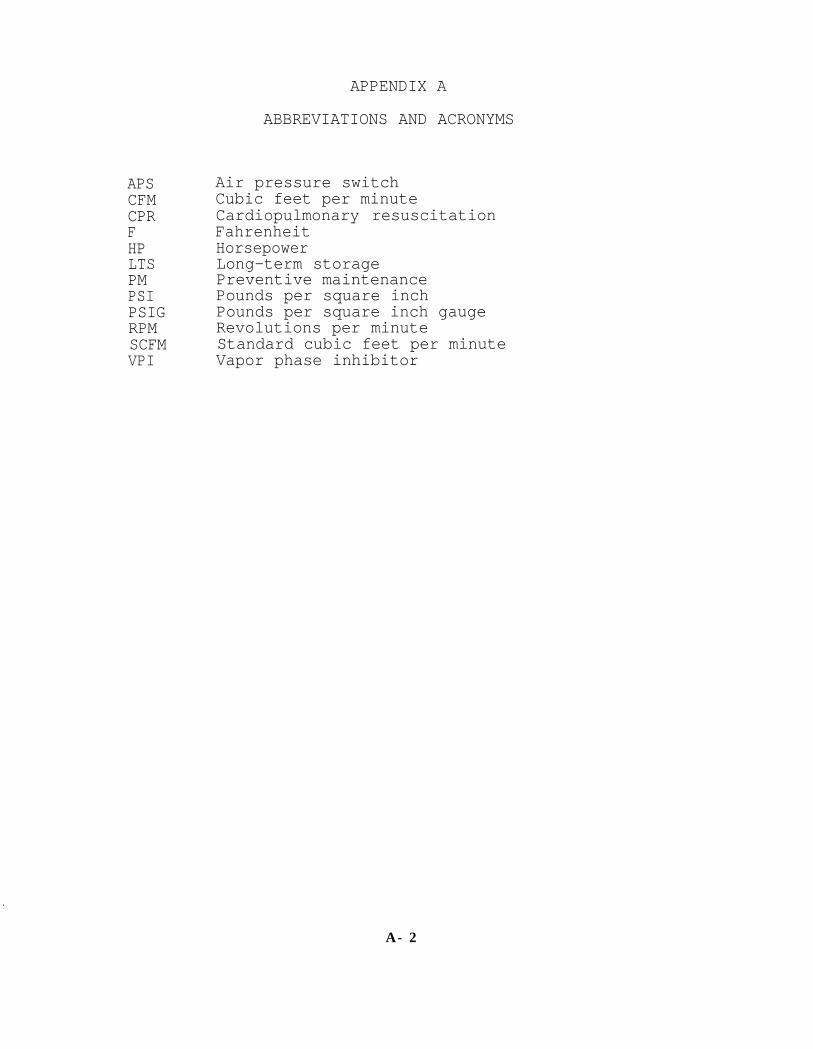
APSCFMCPRFHPLTSPMPSIPSIGRPMSCFMVPI
APPENDIX A
ABBREVIATIONS AND ACRONYMS
Air pressure switchCubic feet per minuteCardiopulmonary resuscitationFahrenheitHorsepowerLong-term storagePreventive maintenance Pounds per square inchPounds per square inch gaugeRevolutions per minuteStandard cubic feet per minuteVapor phase inhibitor
A - 2

APPENDIX B
EVALUATION OF LOSSES IN COMPRESSED AIR SYSTEMS
B-1

APPENDIX B
EVALUATION OF LOSSES IN COMPRESSED AIR SYSTEMS
1 COMPRESSED AIR SYSTEM LEAKS. Leakage of compressed air is a problem atindustrial installations and, if uncorrected, will result in significantmonetary losses (table B-l). Leakage can result from corrosion in undergroundpiping, damaged joints,and defective fittings and valves. A relativelysimple test has been devised which rapidly and economically determines whethera distribution line is leaking and if so, the magnitude of the losses.
2 TEST METHOD. This test requires that a segment of a compressed airdistribution line be pressurized, sealed, and checked by use of a pressuregauge to determine if the line is leaking. If there is no pressure decrease,there is no leakage. If the pressure does decrease, a leak is indicated. Theamount of leakage can be determined and a graph prepared that determines theloss at operating pressure.
3 TEST EQUIPMENT. The following test equipment is simple and inexpensive:
• Pressure gauge
• Stopwatch
4 TEST PRECAUTIONS. This test produces valid results as long as therelationship between pressure and flow rate is linear. Assuming a sonic exitvelocity, the relationship will be linear as long as the ratio of theatmospheric pressure to the line pressure exceeds the critical pressure ratioof 0.53 for gases. Thus, to ensure maximum accuracy, test data should not beused if the pressure gauge registers less than 20 psig.
5 TEST PROCEDURES. The following steps must be performed to complete apressure decay test.
(a) Obtain scale drawings of the section to be tested. Verify drawingsin the field and calculate the volume of the section to be tested.
(b) Install a pressure gauge at a convenient location.
(c) Secure all loads the line supplies.
(d) Isolate the line from the compressed air system.
(e) Immediately begin taking readings at the pressure gauge but do nottry to start the moment the valve is closed. Observe the pressure gauge andbegin timing when the pointer passes a convenient mark. Example: On alOO-psig system, wait for the pressure gauge to reach 95 psig before startingthe stopwatch.
(f) Note the time at convenient pressure intervals (5 or 10 psiincrements). Continue data recording until 20 psig is reached. A suggestedformat for collecting this data in the field is shown in table B-2.
B-2

TABLE B-l. Amount and Cost of Air Leaks
1Airflow is based on nozzle coefficient of 0.64. Costs of air losses based on a systemcontinuously pressurized with compressed air costs of $0.50 per 1,000 cubic feet.
B-3

(g) Using the field data, construct a chart as shown in table B-3. TheLOSS column values (Q) are calculated by using the field data in formula5.1(a).
(h) On graph paper, plot Q on the Y axis and P on the X axis.
(i) Using linear regression, calculate the equation for the best fittingstraight line and solve for Qnominal.(Qnominal is defined as normaloperating pressure.)
TABLE B-2. Pressure Test Data
Pressure Time(psig) (min:sec)
90 0:0080 10:4270 23:1760 38:3450 58:5640 87:2830 135:01
TABLE B-3. Calculation of Losses
Average Pressure Pressure Time Time Loss(psig) (psig) (min:sec) (min) (scfm)
90-8080-7070-6060-5050-4040-30 30-20
85 10:42 10.70 407565
23:17 23.28 3438:34
55 58:5638.57 2858.93 21
45 87:28 87:47 1535 135:01 135.02 925 277:40 277.67 3
B-4

π d2V =1 1 π (10.75 in x 1,000 ft
4 = 4x
12 in/ft )
5.1 Test Formula. In determining the air losses, use the following mass lossformula.
(a) Q = 35.852 V(T+460)(t F-tI)
(PI-PF)
Where: Q = volumetric airflow (scfm)V = volume of tank, ft3T = temperature, °FP = pressure, psigt = time, minutes
FI = initial
= final
(b) Although the regression equation can be calculated by hand, thecalculations are quite laborious. It is strongly recommended that aninexpensive hand-held calculator with statistics capability or an in-housecomputer program be used as the information can then be rapidly and accuratelycalculated.
5.2 Example. The following example illustrates the pressure decay testprocedure.
(a) A section of l0-inch compressed air line is suspected of leakage.The line is located on drawings and verified by a field inspection. Using anengineering scale and the drawing, the length of line is found to be 1,000feet. Calculating the volume of the line:
V = 630.3 ft3
(b) A pressure gauge is installed on the line at an outlet valve, andall loads on the line are secured. With a person watching the gauge, the lineis isolated from the central air distribution system.
(c) The pressure gauge, which had indicated 96 psig, begins to fallimmediately. When the gauge reaches 90 psig, the stopwatch is started. Timeis recorded at l0-psi intervals as shown in table B-2. (A stopwatch with alap counter makes this easier.)
(d) Assuming an ambient temperature of 68°F, the losses can becalculated for each pressure interval, using equation 5.1(a).Results areshown in table B-3.
(e) The data can be plotted as shown in figure B-l to determine how wellthe test data fits a straight line. Although test data from an actual testwill normally be offset from a straight line to some degree, severe deviationswill require that the test be repeated.
B-5

AVERAGE PRESSURE (PSIG)
FIGURE B-l. Loss (cfm) vs Pressure (psig)
(f) Calculating the linear regression formula from the available dataand making the following substitutions:
X = avg press. (P)Y = loss (Q)Y = mX+b
yields the equation: Q = 0.62 P - 12.75.
Losses at operating or nominal pressure (96 psig) are calculated:
Q9 6 = 0.62 (96) - 12.75 Q9 6 = 47 scfm
At a cost of 50 cents for 1,000 cubic feet of compressed air,this represents: $12,35O/year (dollar figure will vary based onfacility costs for compressed air).
6 CORRECTIVE MEASURES. Qnominal represents the loss in the compressed airsystem at operating conditions, assuming a constant pressure over the lengthof pipe in question. This value, taken with the activity's cost to producecompressed air, can be used, as justification,to develop projects to repairor replace sections of compressed air line.
B-6

REFERENCES
1. NAVFAC DM-3.5, Compressed Air and Vacuum Systems.
2. NAVFAC MO-205, Central Heating and Steam Electric Generating Plants.
3. NAVFAC MO-209, Maintenance of Steam, Hot Water. and Compressed AirDistribution Systems.
4. NAVFAC MO-225, Industrial Water Treatment.
5. NAVFAC MO-322, Inspection of Shore Facilities.
6. NAVFAC MO-324, Inspection and Certification of Boilers and UnfiredPressure Vessels.
Reference-l
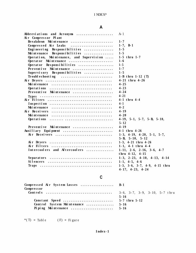
INDEX*
AAbbreviations and Acronyms ....................Air Compressor Plant
Breakdown Maintenance .......................Compressed Air Leaks .......................Engineering Responsibilities ................Maintenance Responsibilities ................Operation, Maintenance, and Supervision .....Operator Maintenance ........................Operator Responsibilities ....................Preventive Maintenance ......................Supervisory Responsibilities ................Troubleshooting ............................
Air Dryers ....................................Maintenance .................................Operations ..................................Preventive Maintenance ......................Types .......................................
Air Filters ...................................Inspection ..................................Maintenance .................................
Air Receivers .................................Maintenance .................................Operations ........ ..........................
Preventive Maintenance ......................Auxiliary Equipment ...........................
Air Receivers ...............................
Air Dryers ..................................Air Filters .................................Intercoolers and Aftercoolers ...............
Separators ..................................Silencers ...................................Traps .......................................
C
Compressed Air System Losses .................. B-1Compressor
Controls .................................... 3-6, 3-7, 3-9, 3-10, 5-7 thru5-16
Constant Speed ........................... 5-7 thru 5-12Control System Maintenance ............... 5-16Piping Maintenance ....................... 5-16
*(T) = Table (F) = Figure
Index-1
A-1
1-71-7, B-11-51-51-5 thru 1-71-61-51-71-51-B thru 1-12 (T)4-21 thru 4-264-254-234-244-214-1 thru 4-44-14-24-194-204-19, 5-1, 5-7, 5-B, 5-10,5-124-194-1 thru 4-261-3, 4-19, 4-20, 5-1, 5-7,5-B, 5-10, 5-121-3, 4-21 thru 4-261-1, 4-1 thru 4-41-11, 2-6, 2-16, 3-6, 4-7thru 4-12, 4-151-3, 2-23, 4-10, 4-13, 4-141-1, 4-5, 4-61-3, 3-6, 3-7, 4-9, 4-15 thru4-17, 4-23, 4-24
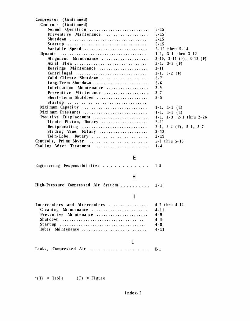
Compressor (Continued)Controls (Continued)
Normal Operation .........................Preventive Maintenance ...................Shutdown .................................Startup ..................................Variable Speed ...........................
Dynamic .....................................Alignment Maintenance ....................Axial Flow ...............................Bearings Maintenance .....................Centrifugal ..............................Cold Climate Shutdown ....................Long-Term Shutdown .......................Lubrication Maintenance ..................Preventive Maintenance ...................Short-Term Shutdown ......................Startup ..................................
Maximum Capacity ............................Maximum Pressures ...........................Positive Displacement .......................
Liquid Piston, Rotary ....................Reciprocating ............................Sliding Vane, Rotary .....................Twin-Lobe, Rotary ........................
Controls, Prime Mover .........................Cooling Water Treatment .......................
E
5-155-155-155-155-12 thru 5-141-1, 3-1 thru 3-123-10, 3-11 (F), 3-12 (F)3-1, 3-3 (F)3-113-1, 3-2 (F)3-73-63-93-73-5
1-1, 1-3 (T)1-1, 1-3 (T)1-1, 1-3, 2-1 thru 2-262-202-1, 2-2 (F), 5-1, 5-72-132-195-l thru 5-161-4
Engineering Responsibilities . . . . . . . . . . . . 1-5
HHigh-Pressure Compressed Air Systems . . . . . . . . . . 2-1
IIntercoolers and Aftercoolers ................. 4-7 thru 4-12Cleaning Maintenance ........................ 4-11Preventive Maintenance ...................... 4-9Shutdown .................................... 4-9Startup ..................................... 4-8Tubes Maintenance ........................... 4-11
LLeaks, Compressed Air . . . . . . . . . . . . . . . . . . . . . . . . . B-1
*(T) = Table (F) = Figure
Index-2

MMaintenance Responsibilities . . . . . . . . . . . . . . . . . . 1-5
0Operator Responsibilities . . . . . . . . . . . . . . . . . . . . . 1-5
PPlant, Air Compressor (See Air Compressor Plant)Prime Mover Controls .......................... 1-1, 1-3, 1-4, 5-1 thru 5-16
Control System .............................. 5-5Cleaning Maintenance ........................ 5-5Lubrication Maintenance ..................... 5-5Motor ....................................... 5-1Normal Operation ............................ 5-4Preventive Maintenance ...................... 5-4Reciprocating Engine ........................ 5-4Shutdown .................................... 5-4Startup ..................................... 5-4Steam Engine ................................ 5-1Steam Turbine ............................... 5-2
RReciprocating Compressor ......................
Bearings Maintenance ........................Belt Drives Maintenance .....................Cleaning Maintenance ........................Extended Shutdown ...........................High Pressure ...............................Lubrication Maintenance .....................Motor Driven Startup ........................New/Overhauled Startup ......................Normal Operation ............................Packing Maintenance .........................Piston Rings Maintenance ....................Preventive Maintenance ......................Safety Precautions ..........................Shutdown ....................................Startup .....................................Steam-Driven Startup ........................
Rotary Liquid Piston ..........................
Bearings Maintenance ........................Lubrication Maintenance .....................Normal Operation ............................Packing Maintenance .........................Preventive Maintenance ......................Shutdown ....................................Startup .....................................
*(T) = Table (F) = Figure
Index-3
1-1, 2-1 thru 2-122-102-102-82-52-12-82-42-42-52-82-92-6, 2-72-12-52-3
1-1, 2-23, 2-24 (F),2-25 (F), 5-122-262-262-232-262-25, 2-262-232-23

Rotary Sliding Vane . . . . . . . . . . . . . . . . . . .
Bearings Maintenance........................Clearances Maintenance......................Cylinders Maintenance.......................Extended Shutdown...........................Lubrication Maintenance.....................Normal Operation............................Preventive Maintenance......................Rotor Blades Maintenance....................Shutdown ....................................Startup .....................................
Rotary Twin-Lobe..............................
Bearings Maintenance........................Lubrication Maintenance.....................Normal Operation............................Preventive Maintenance......................Seals Maintenance...........................Shutdown ....................................Startup .....................................Timing Gears Maintenance....................
SSafety Procedures, High-Pressure Systems ......Separators .............. ........... ...........
Maintenance ....................... ..........Operation .................. .................Preventive Maintenance ......................
Silencers ..................... ................Inspection and Maintenance ..................
Supervisory Responsibilities ..................
TTraps .............. ...........................
Buckets and Floats Maintenance ..............Cleaning Maintenance ........................Levers Maintenance ..........................Preventive Maintenance ......................Shutdown ....................................Startup ......... ........... .................Valves Maintenance ..........................
Troubleshooting ............... ................
1-1, 2-13 thru 2-18,2-14 (F), 5-12, 5-13 (F)2-182-182-172-152-182-152-16, 2-172-172-152-131-1, 2-19 thru 2-22,2-20 (F), 5-122-222-222-212-212-222-212-192-22
2-14-13, 4-144-144-134-134-5, 4-64-51-5
4-15 thru 4-174-174-154-174-154-154-154-171-B (T) thru 1-12 (T)
*(T) = Table (F) = Figure
Index-4