ah4000 series pen type hybrid memory...
TRANSCRIPT
1PSE-806
180mm chart PEN TYPEHYBRID MEMORY RECORDER
AH4000 SERIES
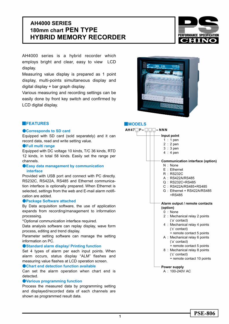
AH4000 series is a hybrid recorder which employs bright and clear, easy to view LCD display.Measuring value display is prepared as 1 point display, multi-points simultaneous display and digital display + bar graph display.Various measuring and recording settings can be easily done by front key switch and confirmed by LCD digital display.
Corresponds to SD cardEquipped with SD card (sold separately) and it can record data, read and write setting value.Full multi rangeEquipped with DC voltage 10 kinds, T/C 36 kinds, RTD 12 kinds, in total 58 kinds. Easily set the range per channels.Easy data management by communication interfaceProvided with USB port and connect with PC directly. RS232C, RS422A, RS485 and Ethernet communica-tion interface is optionally prepared. When Ethernet is selected, settings from the web and E-mail alarm notifi-cation are added.Package Software attachedBy Data acquisition software, the use of application expands from recording/management to information processing.*Optional communication interface required.Data analysis software can replay display, wave form process, editing and trend display.Parameter setting software can manage the setting information on PC.Standard alarm display/ Printing functionSet 4 types of alarm per each input points. When alarm occurs, status display “ALM” flashes and measuring value flashes at LCD operation screen.Chart end detection function availableCan set the alarm operation when chart end is detected.Various programming functionProcess the measured data by programming setting and displayed/recorded data of each channels are shown as programmed result data.
FEATURES
MODELSAH47P--NNN
Input point1 : 1 pen2 : 2 pen3 : 3 pen4 : 4 pen
Communication interface (option)N : NoneE : EthernetR : RS232CA : RS422A/RS485Q : RS232C+RS485C : RS422A/RS485+RS485G : Ethernet + RS422A/RS485
+RS485
Alarm output / remote contacts(option)
0 : None2 : Mechanical relay 2 points
(‘a’ contact)4 : Mechanical relay 4 points
(‘c’ contact)+ remote contact 5 points
A : Mechanical relay 6 points(‘a’ contact)+ remote contact 5 points
8 : Mechanical relay 8 points(‘c’ contact)+ remote contact 10 points
Power supplyA : 100-240V AC

2
AH4000 SERIES
NAME 1 Display
2 Operation/ Setting Key
3 SD card slot 4 Engineering port (USB communication connector)
1. Graphic LCD display
2. Front key switch
Display measured data by digital display and analog indication by bar graph display.
Setting contents can be easily registered by front key switch.
3. SD card slot
Press Menu key and menu screen (list of setting items) will bedisplayed on graphic LCD.
1 point enlarged digital display 1 point enlarged digital display + bar graph display
4 points pointer display 4 points digital display
Save measured data to SD card by designated interval (Fastest 0.1sec). Also, register measuring / recording condition such as range, scale, chart speed and when required, setup the unit by registered conditions.
5. White LED chart illumination
Set ON/OFF/AUTO (OFF after no operation for 3 minutes).
4. Engineering port at the front
Connect with PC by mini-USB cable*. By attached setting software, you can set or change the parameter by PC.*Purchase commercialized product separately.
3
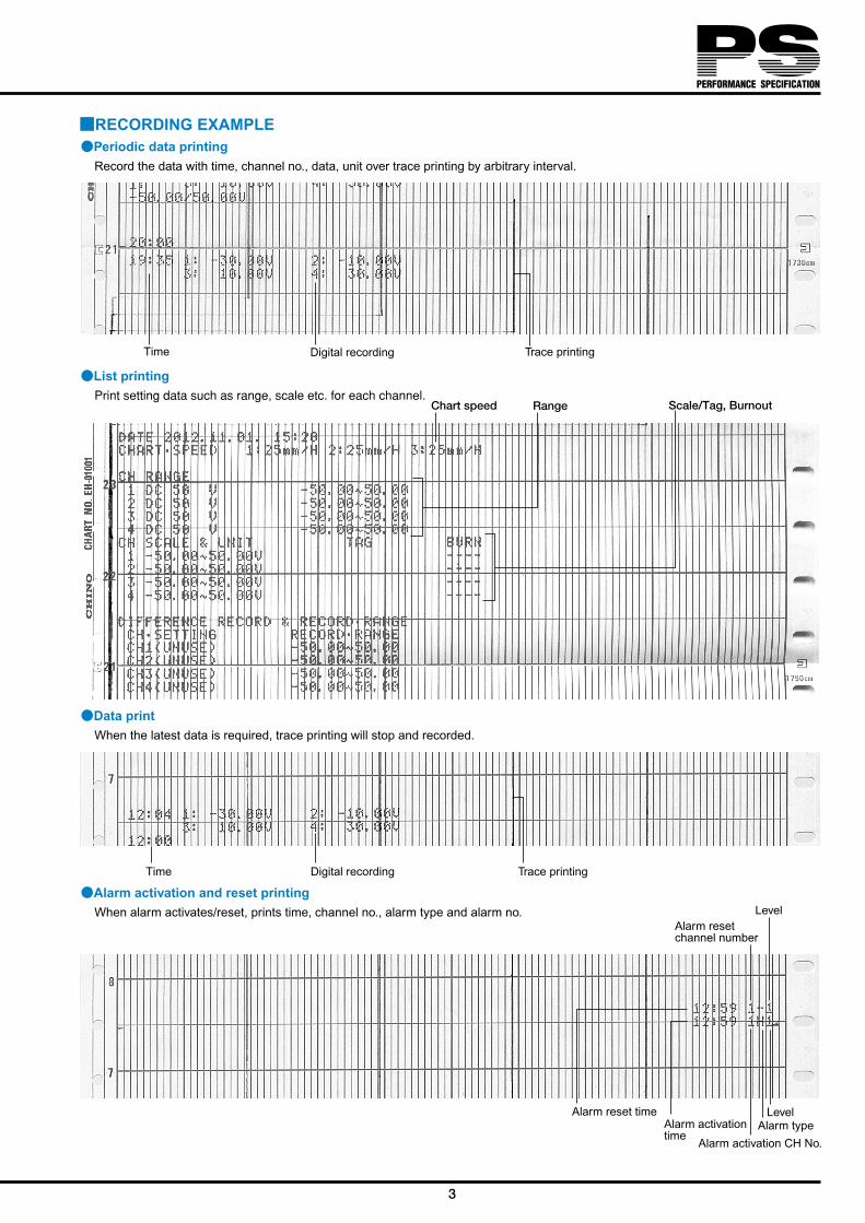
Level
Time Digital recording Trace printing
Time Digital recording Trace printing
Alarm reset timeAlarm activationtime
Alarm resetchannel number
Alarm type
Alarm activation CH No.
Level
RECORDING EXAMPLEPeriodic data printing
Record the data with time, channel no., data, unit over trace printing by arbitrary interval.
Data printWhen the latest data is required, trace printing will stop and recorded.
Alarm activation and reset printingWhen alarm activates/reset, prints time, channel no., alarm type and alarm no.
List printingPrint setting data such as range, scale etc. for each channel.
Chart speed Range Scale/Tag, Burnout

4
AH4000 SERIES
INPUT SPECIFICATIONSMeasuring points: 1 to 4 points Input types: DC voltage --- ±13.8mV, ±27.6mV, ±69.0mV,
±200mV, ±500mV, ±1V±5V, ±10V, ±20V, ±50V
DC current --- Max 50mA by external shunt resistor (100Ω, 250Ω) (sold separately)
Thermocouple ---K, E, J, T, R, S, B, N, U, L, W-WRe26, WRe5-WRe26, PtRh40-PtRh20, NiMo-Ni, CR-AuFe, Platinel, Au/Pt
Resistance thermometer ---Pt100, old Pt100, JPt100, Pt50, Pt-Co
Accuracy ratings: Refer to the table of measuring range/accuracy ratings/display resolution
Measuring interval:Approx. 100msInput resolution: About 1/40,000 or better (converted to
reference range)Input resistance: [Thermocouple/DC voltage: ±5V or lower range)]
6MΩ or higher [DC voltage: ±10V or higher range)] Approx.1MΩ
Reference junction compensation accuracy:At ambient temperature:23±10K, E, J, T, N Platinel---
±0.5 or EMF 20µV, whichever greater
Other than above ---±1.0 or EMF 40µV, whichever greater
Burnout: Burnout detection function for thermocouple input and RTD input. Upper burnout, lower burnout or burnout disabled is selectable for each input.
Allowable signal source resistance :[Thermocouple/DC voltage] Burnout disabled: 1kΩ or lower Burnout enabled: 100Ω or lower [Resistance thermometer] 10Ω or lower per wire(same resistance for 3 wires)
Maximum input voltage:[Thermocouple/DC voltage: ±5V or lower range]±10V or lower[DC voltage: ±10V or higher range] ±60V or lower [Resistance thermometer] ±6V or lower
Measuring current: [Resistance thermometer]1mA ±20%Maximum common mode voltage:
30V AC/60V DCCommon mode rejection ratio:
130dB or more (50/60Hz)Normal mode rejection ratio:
50dB or more (50/60Hz)Terminal board: Removable when wiring.
DISPLAY SPECIFICATIONSAnalog display: LCD bar graph 180mmDigital display: Full dot monochrome LCD
(Backlight AUTO / Always ON settable)Dots : 264 x 48 dotsDisplay area : 184 x 22mm
Display item: All channels simultaneous display, year/month/day, hour/minute, alarm activate channel, chart speed display of measuring value.
Status display: REC, CARD, ALM
ALARM SPECIFICATIONSAlarm display: Status display “ALM” flash, measuring value
flash at operation screenAlarm types: Absolute alarm, differential alarm, rate-of-
change alarm, FAIL, calendar timer, chart end.Alarm settings: Individual settings, Max 4 levels/channelAlarm output: Mechanical relay 2,6,12 output ‘a’ contact
Mechanical relay 4,8 output ‘c’ contact
STANDARDSCE marking: EN61326-1
EN61010-1*Under EMC test condition, variation in indication value is ±20% or ±2mV at maximum,
whichever is larger.UL: UL61010-1CSA (C-UL): CAN/CSA C22.2 No.61010-1
CONNECTIVITYFTP serverWeb
browserApplication
Ethernet
USB port for PC
RS422A / RS485 *Option
DBKPPLC LT
SD card slotSD card
RECORDING SPECIFICATIONSData recording interval:
0.1, 0.2, 0.5,1, 2, 3, 5, 10, 15, 20, 30sec,(SD card) 1, 2, 3, 5, 10, 15, 20, 30, 60minRecording method:Trace printing --- disposable felt-tip pen
Digital printing ---dot type plotter penRecord/Printed color:
Trace printing ---1 pen/red, 2 pen/green,3 pen/blue, 4 pen/brownDigital printing ---purple
Recording interval: 100msStep response: 90%/1.5secRecording deadband:
±0.2%Chart speed: Set arbitrarily from 1 to 600mm/h or 1to
200mm/min, 1mm interval. 12.5mm/h can be set exceptionally.
Chart fast feed: Operated by FEED key Feed 0.1mm by one quick press of the key or feed continuously (approx. 600mm/min) by holding down the key.
Periodic data printing:Digital printing is added to trace printing at month / day, time, channel no., data, unitInterval (hour/time) arbitrary setting.
Data printing: When required, interrupt trace printing and digital print time and measuring value.

5
Alarm printing: Alarm activated --- Time, channel no., alarm type and levelAlarm reset --- Time, channel no., alarm levelMemory capacity --- Max. 48 data
List printing: When required, interrupt trace printing and print date, chart speed and setting information of each channel.
Message printing: Print when requiredUp to 15 characters/message, register up to 20 types.
ON/OFF of display and recording:Select ON / OFF of display trace recording to chart, digital recording to chart, recording to SD card per each channel.
Subtract printing: Record difference between reference channel and measuring value or between reference value (set value) and measuring value.
Zone printing: 2 / 3 / 4 divisionsCompressed/Expanded printing:
A part of printing area of each channel is printing compressed or expanded.
Automatic range shift printing:Recording range is shifted automatically to another set range when measured value exceeds the current range. Overlap function available.
Printing at power-on:Year/month/date and time are printed at power-on.
Printing at recording start:Year/month/date and time are printed at recording start (Rec.OFF→Rec.ON).
Calendar timer printing:Printing is performed with calendar timer ON and printing enabled.Trace printing is continued.Printed items:---Year/month/date/time, calendar timer no. and a message, one message consists of up to 15 characters (alphabets, numbers, katakana, symbols, etc.) and up to 5 types of message is able to register.*Message is shared by message printing
Setting change mark: is printed on the right side of chart when setting change occurs.
Operation recording:Remote contact ON/OFF status is recorded with straight line to specified area. Specified area: Within the range of 0 to 90% Up to 10 types can be recorded. *Only for the unit using remote contact and enabling operation recording.
Chart illumination: White LED ON/OFF/AUTO can be set.
Chart end detection:Notified on the operation screen. After detecting the end of the chart, automaticlly stops recording (the rest operated normally).
Pen up function: Performed automatically at recording stop and chart end. Manual pen up function is available.
Time axis synchronization (POC):ON/OFF can be set at using 2 pen, 3 pen and 4 pen.
Normal operation condition:Ambient temperature range:0 to 50ºC (20 to 65%)Ambient humidity range:20 to 80%RH (5 to 40ºC)Power voltage:90 to 264V ACPower frequency:50/60Hz ±2%Attitude: forward tilting 0º,backward tilting 0 to 30º, left/right 0 to 10º
Memory protection:Set contents and pen type POC data maintained by nonvolatile RAM.Clock data maintained by lithium battery. (Data saved for more than 10 years with 8-hour or more operation per day.)(Alarm message displayed when battery level drops.)
Clock accuracy: ±2 minutes in 30 days (under reference operating condition, error caused by power ON/OFF excluded)
Insulation resistance:Primary terminal – Protective conductor terminal: 20MΩ or more (500V DC)Secondary terminal – Protective conductor terminal: 20MΩ or more (500V DC)Primary terminal – Secondary terminal:20MΩ or more (500V DC)*Primary terminal: General power terminal, alarm output terminal Secondary terminal: All terminals other than primary terminals
Withstand voltage: Primary terminal – Protective conductor terminal: 1500V AC (one minute) basic insulationSecondary terminal – Protective conductor terminal:500V AC (one minute) functional insulationPrimary terminal – Secondary terminal:2300V AC (one minute) reinforced insulation*Primary terminal: General power terminal, alarm output terminal. Secondary terminal: All terminals other than primary terminal.
Case material: Door --- Aluminum die-castingFront panel --- GlassCase --- Cold-rolled steel plate
Case color: Door--- Black (equivalent of Munsell N3.0)Glass--- Clear and colorlessCase --- Gray (equivalent of Munsell N7.0)
Mounting: Panel mountingWeight: Approx. 7.5kg (with full options)Terminal screw: Power terminal,
Protective conductor terminal --- M4.0 Measuring input terminal, alarm output terminalRemote contact terminal --- M3.5Communication terminal --- M3.0
Transportation condition:[Ambient temperature] -10 to 60°C[Ambient humidity] 5 to 90%RH (non-condensing)[Vibration] 4.9m /s2 (10 to 60Hz)[Impact] 392m /s2
*These conditions are set assuming that the unit is packed in a similar way to that at shipment.
Storage condition: [Ambient temperature] -10 to 60°C(10 to 30°C for long-term storage)[Ambient humidity] 5 to 90%RH(non-condensing)[Vibration] 0m /s2 (10 to 60Hz)[Impact] 0m / s2
*These conditions are set assuming that the unit is packed in a similar way to that at shipment. Readjustment may required.
GENERAL SPECIFICATIONSRated power voltage:
100 to 240VAC, 50/60HzPower consumption:
MAX 40VA
TRANSPORTATION & STORAGE SPECIFICATIONS

6
AH4000 SERIES
-13.8 to 13.8mV-27.6 to 27.6mV-69.0 to 69.0mV-200 to 200mV-500 to 500mV
-1 to 1V-5 to 5V
-10 to 10V-20 to 20V-50 to 50V
-200 to 300ºC-200 to 600ºC-200 to 1370ºC-200 to 200ºC-200 to 350ºC-200 to 900ºC-200 to 250ºC-200 to 500ºC-200 to 1200ºC-200 to 250ºC-200 to 400ºC
0 to 1200ºC0 to 1760ºC0 to 1300ºC0 to 1760ºC0 to 1820ºC
-200 to 400ºC-200 to 750ºC-200 to 1300ºC-200 to 250ºC-200 to 500ºC-200 to 600ºC-200 to 250ºC-200 to 500ºC-200 to 900ºC
0 to 2315ºC0 to 2315ºC0 to 290ºC0 to 600ºC0 to 1310ºC0 to 350ºC0 to 650ºC0 to 1390ºC0 to 1880ºC0 to 280 K0 to 1000ºC
-140 to 150ºC-200 to 300ºC-200 to 649ºC-200 to 850ºC-140 to 150ºC-200 to 300ºC-200 to 649ºC-140 to 150ºC-200 to 300ºC-200 to 649ºC-200 to 649ºC
4 to 374K
MEASURING RANGES/ACCURACY RATING/DISPLAY RESOLUTION
10µV10µV10µV
100µV100µV10mV10mV10mV10mV10mV0.1ºC0.1ºC1 ºC
0.1ºC0.1ºC1 ºC
0.1ºC0.1ºC1 ºC
0.1ºC0.1ºC1 ºC1 ºC1 ºC1 ºC1 ºC
0.1ºC0.1ºC1 ºC
0.1ºC0.1ºC0.1ºC0.1ºC0.1ºC1 ºC1 ºC1 ºC
0.1ºC0.1ºC1 ºC
0.1ºC0.1ºC1 ºC1 ºC
0.1 K0.1ºC0.1ºC0.1ºC0.1ºC0.1ºC0.1ºC0.1ºC0.1ºC0.1ºC0.1ºC0.1ºC0.1ºC
0.1 K
±13.8mV±27.6mV±69.0mV±200mV±500mV
± 1V± 5V± 10V± 20V± 50V
±13.8mV±27.6mV±69.0mV±13.8mV±27.6mV±69.0mV±13.8mV±27.6mV±69.0mV±13.8mV±27.6mV±13.8mV±27.6mV±13.8mV±27.6mV±13.8mV±13.8mV±27.6mV±69.0mV±13.8mV±27.6mV±69.0mV±13.8mV±27.6mV±69.0mV±69.0mV±69.0mV±13.8mV±27.6mV±69.0mV±13.8mV±27.6mV±69.0mV±13.8mV±6.9mV±27.6mV
160Ω220Ω340Ω400Ω160Ω220Ω340Ω160Ω220Ω340Ω220Ω
220Ω
Input type Measuring range Reference range Accuracy ratings Displayresolution
K
E
J
T
R
B
S
N
U
L
W-WRe26WRe5-WRe26
NiMo-Ni
Platinel
PtRh40-PtRh20CR-AuFe
Au/Pt
Pt100
JPt100
Pt50
Pt-Co
mV
V
Old Pt100
±0.1%±1digit
±0.1%±1digit
±0.15%±1digit
±0.1%±1digit
±0.2%±1digit
±0.2%±1digit
±0.15%±1digit
±0.15% ±1digit
Note: The accuracy ratings are converted into the measuring range under referencecondition. Thermocouple input does not contain reference junction compensationaccuracy.K, E, J, T, R, S, B, N : IEC584(1977, 1982), JIS C 1602-1995, JIS C 1605-1995W-WRe26, NiMo-Ni, Platinel, PtRh40-PtRh20, CR-AuFe, Au/Pt : ASTM E1751WRe5-WRe26 : ASTM E988 U, L : DIN43710-1985Pt100 : IEC751(1995), JIS C 1604-1997Old Pt100 : IEC751(1983), JIS C 1604-1989, JIS C 1606-1989JPt100 : JIS C 1604-1981, JIS C 1606-1986, Pt50 : JIS C 1604-1981 Pt-Co : CHINO
RT
DD
C voltage
Therm
ocouple
OPTIONS
ACCESSORIES
Remote contact: By external relay contact signal(digital contact: short or open), you can select chart speed or data printingInput points: 5 points, 10 pointsInput signal: Digital contact signal or open
collector signalContact capacity: 5V DC/2mAFunction: 1. Record start/stop
2. Chart speed 3-speed switch 3. Data printing 4. List printing 5. Message printing 6. Operation record (Record ON/OFF condition to the designate location by bar line) 7. Integration/F value reset 8. Memory card (record start/stop) 9. Alarm output rest10.Time correction
Alarm output: Mechanical relay (‘a’ contact) 2 points, 6 points12 pointsMax. load 100 to 240VAC 0.2A30V DC 0.2AMin. load 5V DC 10mA
Mechanical relay (‘c’ contact) 4 points, 8 points, Max. load 100 to 240VAC 0.2A30V DC 0.2AMin. load 5V DC 10mA
Communication interface: RS232C, RS422A, RS485, Ethernet*Combination is depending on the model
Model : RZ-SMC512Model : RZ-SMC1GModel : RZ-SMC2G
512MB1GB2GB
SD Card

7
-200 to 0ºC
-200 to 0ºC
0 to 400ºC
0 to 400ºC
400 to 800ºC
0 to 400ºC
0 to 400ºC
400 to 800ºC
0 to 20 K
20 to 50 K
4 to 20 K
20 to 50 K
K、E、J、N、U、L
T
R、S
B
W-WRe26
PtRh40-PtRh20
CR-AuFe
Pt-Co
±0.2%±1digit or equivalent of 70µV,
whichever is larger.
±0.2%FS±1digit
±0.2%FS±1digit
Not defined
±0.2%FS±1digit
±0.3%FS±1digit
±1.5%FS±1digit
±0.8%FS±1digit
±0.5%FS±1digit
±0.3%FS±1digit
±0.5%FS±1digit
±0.3%FS±1digit
Exceptions for accuracy ratingsInput type Exceptional range Accuracy rating
TERMINAL ARRANGEMENT
Power/protective conductive terminals
Remote contact terminals (option)
Ethernet connector
Ethernet connector
1 2 3 4 5 6 7 8 SG SD RD SG SDA SDB RDA RDB SA SB SG
RS-232C
RS-485RS-422A
1 2 3 4 5 6 7 8 SG SD RD SG SDA SDB RDA RDB SA SB SG
RS-232C
RS-485RS-422A
L PEN
100-240V AC
L PEN
100-240V AC
Alarm relay output (12 points ‘a’ contact) + remote contacts (10 points) and communication interface
Alarm relay output (8 points ‘c’ contact) + remote contacts (10 points) and communication interface
Alarm output terminals (option)N.O terminalCOM terminal
Measurement input terminalsTC.mV(+), RTD(A) terminals
TC.mV(-), RTD(B) terminalsminalsRTD(B) terminals
Communication terminal
Measurement input terminalsTC.mV(+), RTD(A) terminals
TC.mV(-), RTD(B) terminalsminalsRTD(B) terminals
Communication terminal
Power/protective conductive terminals
Remote contact terminals (option)
Alarm output terminals (option)

DIMENSIONS
Panel cutout
Unit :mm
*Max241, When alarm output/remote contacts unit and communication unit are added.
APPLICATION SOFTWARE (standard attached)Data Acquisition SoftwareYou can acquire data easily to your PC. Parameter Setting Software
Control the setting information at PC by using communicationinterface or USB port (standard equipped)
Data Analysis SoftwareOpen the binary file recorded in the SD card, replay display and edit the trend of acquired data file.
*Optional communication interface required
List Data Screen
Trend Data Screen
(Max220, When Ethernet unit are added.)
Specifications subject to change without notice. Printed in Japan (I) 2013. 6
32-8 KUMANO-CHO,ITABASHI-KU,TOKYO 173-8632Telephone : +81-3-3956-2171Facsimile : +81-3-3956-0915E-mail : [email protected] : www.chino.co.jp/
360
281 +1 0
281+
1
0
360
288
288
297.6
38179
26.5
27
7.6
88.8
220