agu word manuscript template dynamic accretion beneath a
TRANSCRIPT
Confidential manuscript submitted to Journal of Geophysical Research, Solid Earth
AGU Word Manuscript Template Dynamic accretion beneath a slow-spreading ridge segment: IODP Hole 1473A and
the Atlantis Bank Oceanic Core Complex H.J.B. Dick1*, C.J. MacLeod2, P. Blum3, N. Abe4, D.K. Blackman5, J.A. Bowles6, M.J. Cheadle7, K. Cho8, J. Ciążela9, J.R. Deans10, V.P. Edgcomb1, C. Ferrando11, L. France12, B. Ghosh13, B. Ildefonse11, B. John7, M.A. Kendrick14, J. Koepke15, J.A.M. Leong16, C. Liu17, Q. Ma18, T. Morishita19, A. Morris20 J. H. Natland21, T. Nozaka22, O. Pluemper23, A. Sanfilippo24, J.B. Sylvan25, M.A. Tivey1, R. Tribuzio24, G. Viegas26
1 Dept. of Geology & Geophysics, Woods Hole Oceanographic Institution, Woods Hole MA, USA. 2 Dept. of Earth Sci., Cardiff University Cardiff Wales, United Kingdom. 3 International Ocean Discovery Program, Texas A&M University, College Station TX, USA. 4 Ocean Drilling Science, Japan Agency for Marine-Earth Sci. & Technology, Yokosuka Kanagawa, Japan. 5 Scripps Institution of Oceanography, University of California, San Diego, La Jolla CA, USA. 6 Dept. of Geoscience, University of Wisconsin-Milwaukee, Milwaukee WI, USA. 7 Dept. of Geology & Geophysics, University of Wyoming, Laramie WY, USA. 8 Dept. of Environmental Exploration Engineering, Pukyong National University, Republic of Korea. 9 Institute of Geology, Adam Mickiewicz University, Poznan, Poland. 10 School of Biological, Environmental, and Earth Sci., University of Southern Mississippi, USA. 11 Geosciences Montpellier, CNRS, University of Montpellier, Montpellier, France. 12 Centre de Recherches Pétrographiques et Géochimiques, CNRS, Université de Lorraine, Nancy, France. 13 Dept. of Geology, University of Calcutta, Kolkata, India. 14 Research School of Earth Sci., The Australian National University, Acton, Australia. 15 Institut fuer Mineralogie, University of Hannover, Hannover, Germany. 16 School of Earth & Space Exploration, Arizona State University, Tempe AZ, USA. 17 Institute of Geology & Geophysics, Chinese Academy of Sci., Beijing 100029, China. 18 School of Ocean & Earth Sci., Tongji University, 1239 Siping Road, Shanghai, China. 19 Kanazawa University, College of Sci. & Engineering, Kanazawa, Ishikawa, Japan. 20 School of Geography, Earth, & Environmental Sci., University of Plymouth, United Kingdom. 21 Rosenstiel School of Marine & Atmospheric Sci., University of Miami, Miami FL, USA.

Confidential manuscript submitted to Journal of Geophysical Research, Solid Earth
22 Dept. of Earth Sci., Okayama University, Okayama, Japan. 23 Department of Earth Sci., Utrecht University, Utrecht, Netherlands. 24 Dipartimento di Scienze della Terra e dell’Ambiente - Università degli Studi di Pavia, , Pavia, Italy. 25 Dept. of Oceanography, Texas A&M University, College Station TX, USA. 26 Instituto de Geociências, Universidade de Brasília, Brasília, DF, Brazil.
Corresponding author: Henry J. B. Dick ([email protected])
Key Points:
• No evidence of a high level melt lens with gabbros intruded at depth, then emplaced to high levels by crystal mush diapirism and plastic deformation and faulting.
• Diving over the crust-mantle boundary on the transform wall found no primitive cumulates and evolved gabbro was intruded directly into the mantle at the transform.
• Primitive cumulates needed to mass balance MORB must lie at depth near the crust-mantle boundary, while the few diabase dikes encountered intrude the gabbro
Confidential manuscript submitted to Journal of Geophysical Research, Solid Earth
Abstract 809-mbsf IODP Hole U1473A at Atlantis Bank, SWIR, is 2.2 km from 1508-m Hole 735B and 1.4 from 158-m Hole 1105A. With mapping, it provides the 1st 3-D view of the upper levels of a 660-km2 lower crustal batholith. It is laterally and vertically zoned, representing a complex interplay of cyclic intrusion, and ongoing deformation, with Km-scale upward and lateral migration of interstial melt. Transform wall dives over the gabbro-peridotite contact found only evolved gabbro intruded directly into the mantle near the transform. There was no high-level melt lens, rather the gabbros crystallized at depth, and then emplaced into the zone of diking by diapiric rise of a crystal mush followed by crystal-plastic deformation and faulting. The residues to mass balance the crust to a parent melt composition lie at depth below the center of the massif – likely near the crust-mantle boundary. Thus, MORB’s erupted to the seafloor from >1,550-mbsf. The MAR lower crust drilled at 23°N and Atlantis Massif experienced little high-temperature deformation and limited late-stage melt transport. They contain primitive cumulates, and represent direct intrusion, storage, and crystallization of parental MORB in thinner crust below the dike-gabbro transition. The strong asymmetric spreading of the SWIR to the south was due to fault capture, with the northern rift valley wall faults cut off by a detachment fault that extended across most of the zone of intrusion. This caused rapid migration of the plate boundary to the north, while the large majority of the lower crust to spread south.
1 Introduction
Direct knowledge of the nature of the lower ocean crust and crust-mantle boundary is limited; largely from scattered dredges and isolated dives on oceanic core complexes, transforms, and rift valley walls, so its composition and architecture have been poorly constrained. Atlantis Bank on the SW Indian Ridge (SWIR) (Fig. 1) exposes an enormous 660-km2 batholith comprised of lower ocean crust emplaced by detachment faulting into the rift mountains of the SW Indian Ridge. This occurred in a region of high current activity and low sedimentation, too far south to have been covered by reef corals (Darwin, 1842), unlike similar massifs covered by reef building coral in the equatorial Atlantic. This, together with late uplift, faulting, and mass wasting permitted geologic mapping and drilling to provide the first detailed view of the upper ~1500-m of the lower ocean crust accreted at an ultraslow spreading ridge. It formed, beginning at 13 Ma (Baines et al. 2008), over ~3 Myr at a single 2nd-order ridge segment. IODP Expeditions 360 and 362T drilled Hole U1473A 809.4 m into the center of this gabbro massif, initiating the ‘SloMo” project (The Nature of the Lower Crust and Moho at Slow-spreading Ridges), a multiphase program to drill through the crust and seismic Moho.
Geological mapping (Fig. 2, Dick et al., 2019) and drilling at Atlantis Bank demonstrates a process of dynamic accretion unlike the passive magmatic accretion at the East Pacific Rise where intrusion of magma accommodates extension with little tectonic extension in the lower crust. Dynamic accretion occurs where magmatism is ephemeral, as at slow and ultraslow-spreading ridges. A considerable proportion of extension in the lower crust across the plate boundary is taken up by tectonic processes, initially by deformation of crystal mush that then transitions to crystal-plastic flow and faulting. Unlike the EPR, there is no melt lens, and no sharp interface between gabbros and overlying dikes; unlike layered intrusions there is little evidence for large km-scale magma chambers or unambiguous evidence of magmatic sedimentary layering. Instead there is a tectono-magmatic stratigraphy produced through the complex interplay of episodic intrusion, permeable melt migration, crystal-plastic deformation

Confidential manuscript submitted to Journal of Geophysical Research, Solid Earth
and continuous extension driven by separation of the tectonic plates. There is a continuity of igneous and tectonic processes along a lithospheric flow line, and a strong along-axis lateral variability of crustal architecture from paleo-segment center to its distal end, reflecting compaction, adcumulate growth, and deformation driven vertical and lateral differentiation of the massif to highly evolved gabbro with a central olivine gabbro core (Fig. 3). Atlantis Bank represents an unusually robust and large magmatic center, a true batholith, compared to lower crust exposed by detachment faulting at the best-known core complexes in the Atlantic: Kane Megamullion (23°N), Dante’s Dome (26°N) and Atlantis Massif (30°N). These appear to represent relatively small magmatic centers roughly 100 to 270 km2 in extent (Canales et al., 2008); the largest, the Kane Massif, only <40% the size of the Atlantis Bank gabbro massif.
2 Tectonic Setting
Atlantis Bank is located at 57°E south of ridge segment AN1 in the rift mountains of the ultraslow-spreading SWIR (14 mm/yr) adjacent to the 199-km offset Atlantis II Transform (Fig. 1). The spreading rates at segments AN1 to the east and GA2 to the west are highly asymmetric, with the transform lengthening at ~3.6 mm/y for the past ~24 Myr (Baines et al., 2007; Dick, 1991; Hosford et al., 2003). The transverse ridge flanking the transform has a series of uplifted blocks and saddles (Dick, 1991) of which Atlantis Bank is the shallowest and northernmost. Segment AN1 magnetic anomalies give ~13.8 mm/yr to the south and ~4.6 mm/yr to the north during emplacement of Atlantis Bank or from ~13.4 to ~10.5 Ma based on the magnetic anomalies, zircon ages (Baines et al., 2008). The gabbro massif is located from 79 to 116 km south of the ridge, representing continuous emplacement of massive gabbro into the rift mountains for ~3 Myr. It consists of a raised dome ~37-km long by ~30-km wide, rising from 5,700 m at the transform floor to 689 m at a ~25 km2 wave-cut platform, and then drops across two transform-parallel East-dipping normal faults to 4,300 m depth on its eastern flank (Baines et al., 2003; Dick, 1991; Hosford et al., 2003). While initial uplift occurred at the ridge-transform intersection, a 10° counterclockwise change in regional spreading direction at ~19 Ma put the transform into transtension for ~12 Myr resulting in substantial additional uplift (Baines et al., 2007; Baines et al., 2008; Dick, 1991).
The 660-km2-gabbro massif is the largest known in the oceans, while the Atlantis II Transform exposes by far the largest abundance of gabbro anywhere on the SW Indian Ridge. SWIR crust is typically thin, with a reduced magmatic component compared to crust formed at other ocean ridges (Zhou and Dick, 2013), the explanation for which is generally the ultraslow-spreading rate (Bown and White, 1994; Reid and Jackson, 1981), its extreme obliquity compared to others (Dick et al., 2003; Montési and Behn, 2007; Püthe and Gerya, 2014), and likely a colder than normal mantle (Husson et al., 2015). The original magmatic crustal thickness of Atlantis Bank, prior to detachment faulting must be significantly >4.0 km crust based on the estimated overburden of dikes and lavas (Vanko and Stakes, 1991) and the present depth and composition of Hole 735B (Dick et al., 2019), exceptionally thick for SWIR. This is attributed to an unusually fertile mantle source (Dick et al., 2019) and a consequently greater melt supply than at the ridge segments immediately to the west.
Asymmetric spreading and formation of the Atlantis Bank core complex occurs due to fault capture (Dick et al., 2019), where the detachment fault extended below the dikes and pillow lavas out over the zone of accretion, cutting off the normal faults beneath the opposing rift valley wall (Fig. 4). Thus, the lower crust and mantle spread continuously to the south as it accreted,

Confidential manuscript submitted to Journal of Geophysical Research, Solid Earth
even as spreading consequently stalled to the north. Though apparently intact volcanic crust formed and slowly spread to the north at ~4.6 mm/yr, the plate boundary also migrated north compensating for the spreading asymmetry. Asymmetric seafloor spreading represents up to 50% of the crust along the northern Mid-Atlantic Ridge (Escartin et al., 2008; Smith et al., 2008). If asymmetric spreading occurs where 50% or less of total extension is accommodated by magmatic accretion (Tucholke et al., 2008), Atlantis Bank, as the most magmatically robust oceanic core complex, would then come closest to exposing ‘average’ slow-spread lower crust. ‘Average’, keeping in mind that the ocean crust at slow and ultraslow spreading ridges ranges from zero along many sections of the SW Indian Ridge, to 18-km thick near the northern end of the Reykjanes Ridge. Symmetric spreading, where intact volcanic crust spreads equally in both directions, is a related but different accretionary mechanism, and the differences in crustal structure are likely significant. Thus, using Atlantis Bank as a direct analogue for crust formed by symmetric spreading should be done with caution.
3 Geology of Atlantis Bank
The site surveys of Atlantis Bank include multibeam, magnetics, and gravity, as well as dredging, seabed rock coring, and ROV and submersible sampling (Dick et al., 1991b; MacLeod et al., 1998; Arai et al., 2000; Kinoshita et al., 1999; Matsumoto et al., 2002). Initial studies of the gabbros and mantle rocks, as well as the structure and tectonics have been published (Allerton and Tivey, 2001; Dick, 1991; Dick et al., 1991b; Matsumoto et al., 2003; Miranda and John, 2010; Schwartz et al., 2005). A synthesis of these results (Dick et al., 2019), with a new analysis of the seafloor samples, mineral data for the seafloor gabbro suite, and a detailed geologic map (Fig. 2), provides the basis for the following review of the geology.
The wave-cut platform at the crest of Atlantis Bank has a broadly flat surface ranging from ~750 to 689 mbsl. A central pavement exposes bare rock consisting largely of submerged gabbro sea stacks surrounded by indurated bioclastic beach sand and local carbonate-cemented pebble conglomerate (Dick et al., 2019; MacLeod et al., 1998; Palmiotto et al., 2013). Seabed rockdrills cored often highly deformed gabbro and 2 diabase dikes at 35 locations on the platform (MacLeod et al., 1998). Serpentinized peridotite and pillow-basalt breccia were also cored at its southern tip where the platform narrows into a north south spine exposing the uneroded footwall of the detachment fault. Many of the gabbro outcrops in the ROV images are flat-lying mylonites (Dick et al., 2019), however in the shallow rockdrills, Hole 735B, and Hole 1105A the variably dipping foliations are generally not conformable to those imaged by ROV on the platform, with the rockdrill cores having average dips of 26° (MacLeod, pers. com. 2016) and 36° for Hole 735B (Cannat, 1991; Dick et al., 1991a; Miranda and John, 2010; Robinson, 1989).
The uneroded seafloor below the Atlantis Bank platform represents a detachment fault footwall and damage zone (Dick et al., 2019). This damage zone consists of a ~meter thick, possibly continuous talc-serpentine schist that was intruded up the active detachment fault from where it cut into the mantle near the transform fault zone. Similar intrusions are commonly seen along faults on-land, particularly in the Klamath Mountains of Northern California and Oregon. They occur where faults cut across multiple lithologies, such as a gabbro massif in contact with mantle peridotite. The serpentinite and talc-serpentine schists, form due to fluid circulation in the fault zone where it cuts peridotite, then due to its low strength and density, migrates along the fault zone to where it intrudes into the adjoining lithology.

Confidential manuscript submitted to Journal of Geophysical Research, Solid Earth
Beneath the schist there is a thin zone (meters) of diabase or gabbro cataclasites and breccias, sometimes polymict, which accordingly represent brittle faulting prior to intrusion of the talc and serpentine. These include greenschist and amphibolite facies rocks as well as fragments of gabbro mylonites. Where observed in outcrop, these breccias are massive, not loose rubble, with matrix cemented clasts. Beneath the cataclasites, a thick mylonitic zone is observed consisting largely of crystal-plastically deformed oxide gabbro, with intercalations of olivine gabbro (e.g., Fig. 3a, left panel). The oxide gabbros formed by melt-rock reaction due to percolation of late Fe-Ti rich melts along shear zones in the older olivine gabbro (Dick et al., 2019). Thus, the detachment fault rooted into the top of an intermittently replenished crystal mush zone extending from the midpoint of the AN1 segment (Dick et al., 1991a, 2000; Natland and Dick, 2001, 2002).
The gabbros in Hole 735B and 1105A are nearly all adcumulates, and have plagioclase compositions (~An34-67) too evolved to be the residues of all but the most fractionated MORB’s sampled on the AN1 ridge segment to the north (Dick et al., 2019). There is abundant evidence of hypersolidus deformation, most easily seen macroscopically in the oxide gabbros, but also present in microfabrics in the olivine gabbros (e.g., Moss, 2016). In addition to the oxide gabbro mylonites in the footwall, there is abundant evidence of large-scale upward permeable transport of intercumulus melt through the gabbro massif in both in Holes 735B and 1105A and in the seafloor sample suite. This is seen most prominently in the large-scale local mineral disequilibrium combined with a progressive overall upward iron enrichment of the Hole 735B olivine gabbros in the major igneous units, and also in the abundance of Fe-Ti rich oxide gabbros high in the section.
One hundred and forty-seven diabase and 47 pillow basalts were recovered by dredging and submersible sampling. While the diabase is generally altered in the greenschist facies, the pillow lavas are only weathered, preserving fresh glass and relict olivine, and are not hydrothermally altered (Dick et al., 2019). Given the state of the pillow lavas, this material is detached hanging wall debris rafted on the detachment fault surface. The proportions are those expected for a hanging wall composed of pillow lavas and sheeted dikes. However, in outcrop, beneath the fault damage zone, inliers of the dike-gabbro transition were observed and sampled by ROV and submersible. In outcrop the dikes strike ~North 80° West and 60° to 70° to the north (Dick et al., 2019), indicating a back-tilt of 20° to 30° from an assumed vertical initial orientation. However, only 7 dikes were found in Hole U1473A, one in 735B, and none in 1105A, and were only drilled twice on the platform. The strong contrast in dike proportions between the seafloor samples and the drill holes is direct evidence that massive sheeted dikes originally overlay Atlantis Bank.
Thus, the detachment fault rooted through the dike-gabbro transition to expose the gabbro. In every case, unlike the dike-gabbro transition in the Pacific, where gabbros cut the dikes (France et al., 2009; Natland and Dick, 1996; Wilson et al., 2006), the Atlantis Bank dikes cut crystal-plastically deformed gabbro, there is no sharp boundary between the two, and no evidence of a melt lens. Instead in outcrop there is a transition over several hundred meters from massive dikes through mixed dikes and gabbro to massive gabbro (Dick et al., 2019). The gabbros originally crystallized at high temperature, and were then emplaced mechanically upwards, first by hypersolidus flow and then by solid-state deformation through the granulite and upper amphibolite facies. The crosscutting dikes exhibit only brittle deformation and alteration

Confidential manuscript submitted to Journal of Geophysical Research, Solid Earth
was static largely in the greenschist facies, reflecting the final wall rock temperature at the time of intrusion.
Five DSRV Shinkai 6500 crossings of a gabbro-peridotite contact on the transform wall found coarse-grained moderately to highly evolved gabbro directly above massive protogranular and porphyroclastic mantle peridotite (Fig. 2) (Dick et al., 2019). The most primitive of these, those drilled, and the rest of the seafloor suite, could only have crystallized from a MORB that had undergone 40% crystallization, and over ~95% of the seafloor samples are too fractionated to have crystallized from Segment AN1 MORB (Dick et al., 2019). Thus, they are products of more evolved melts, or represent more primitive gabbro impregnated by later evolved melts – or a combination of both. The absence of primitive cumulates in the seafloor suite, and dunite sampled with peridotite on the transform wall, shows there was little mantle melt transport to the crust at the distal end of the AN1 segment (Dick et al., 2019). Mass balance for a likely parental melt then requires that these primitive cumulates must exist at depth in the crust beneath the segment center (Fig. 3), and/or in the underlying mantle. In turn, MORB compositions erupted at the paleo-ridge must also be largely controlled by fractionation and melt-rock reaction at depth (e.g., Lissenberg and Dick, 2008; Sanfilippo et al., 2013), with only secondary modification during transport to the seafloor.
Figure 3a, reproduced from Dick et al. (2019) shows two key dive sections on the western transform wall of the Atlantis II Transform, the eastern wall of the bank, and downhole logs for Hole 735B which, together with additional Site Survey data provide a basis for interpretation of its geology in an east west ridge parallel profile. Note that dunites, the earliest primitive cumulates are postulated to lie at the crust-mantle boundary far above the Moho in Figure 3b, and that the contact between crust and mantle exposed on the transform wall is between dominantly coarse highly evolved oxide gabbro intruded over coarse granular lherzolite. As the gabbro-peridotite contact is intrusive, however, and we do not know its precise orientation, the base of the gabbro body could lie anywhere down to the Moho (e.g., Fig. 3c).
4 Operations
Hole1473A is located at 32°42.3622’S 57°16.6880’E, 710 m below sea level (Fig. 2). It is 2.2 km north northeast of 1,508-m deep Hole 735B drilled by ODP Leg 118 in 1987 and IODP Leg 176 in 1997, and 1.4 km north of 158-m deep Hole 1105A drilled by IODP Leg 179 in 1998. Expedition 360 drilled 789.7 m, recovering 469.4 m of core with average recovery of 59%, with >96% in the lower 200 m. (86%). Unlike Holes 735B and 1105A, Hole U1473 was spudded into the hanging wall of an east west normal fault, intersecting it at depth, with a damage zone down to ~469 mbsf. The unstable drilling conditions, low core recovery, and lost hardware, led to Expedition 362T revisiting the hole to clean, deepen, and stabilize it by cementing. Only the Expedition 360 segment was logged. While it was deepened to 809.4-mbsf (16.6-m of additional core) cementing was only partly successful (Blum et al., 2017). Although compromised for deeper drilling due to instability in the fault zone, and a missing drill cone likely embedded in the wall of the hole, the principle expedition objective of determining the lateral variability of the gabbro massif was successful.

Confidential manuscript submitted to Journal of Geophysical Research, Solid Earth
5 Results from IODP Hole U1473A
5.1 Igneous petrology
The igneous stratigraphies and mineral modes of Holes U1473A, 735B and 1105A are all similar (Fig.’s 5 and 6). We note that here we use units and nomenclature for Hole 1105A as described by the Expedition 360 scientists, which differ somewhat from what was described by the ODP Leg 179 scientists, as we used lithologic definitions that conform to those used on ODP Leg 176. The U1473A cores range from olivine gabbro to oxide-rich gabbro, cut by numerous microgabbros, felsic veins, and rare diabase dikes. Eight lithologic units, and 424 igneous intervals were defined on the basis of changes in mineral mode, grain size, and texture, as well as igneous layering, felsic veins, magnetic susceptibility, and bulk chemistry. By comparison 13 units and 957 intervals were described in Hole 735B (Table S1). The main lithology is coarse to medium grained intergranular and equigranular olivine gabbro (76.5%, <1% oxide), with only 5.1% gabbro (<5% olivine) (e.g., Fig.’s 5a, 6). Grain-size can be highly variable, often in long sections of patchy olivine gabbro, where grain size ranges from fine to very coarse (e.g., Fig. 7b). Primary textures are often obscured by ubiquitous crystal-plastic deformation, much of it hypersolidus (e.g., Fig.’s 5a, d; 7a and d). Where preserved, magmatic textures are mostly subophitic or granular.
Oxide gabbros (sensu lato >1% ilmenite and titanomagnetite) occur throughout Hole U1473A, often in centimeter-scale intervals in crosscutting relationships with the olivine gabbros. These include 9.5% disseminated-oxide gabbro (1- 2% oxide) by volume, 3.7% oxide-bearing gabbro (2-5% oxides), and 3.7% oxide gabbro (>5% oxides). Unless otherwise specified, ‘oxide gabbro’ in the text is ‘sensu lato’, meaning oxide contents >1% by volume. Accessory interstitial brown amphibole often rims clinopyroxene (Cpx) and around olivine, sometimes in combination with orthopyroxene. Such late-stage melt-related features are less abundant in undeformed samples deep in the hole. Oxide abundance decreases slightly downhole, except below > 650 mbsf) where a somewhat larger proportion of oxide-bearing gabbros occur. As in Holes 735B and ll05A, gabbros with >1% oxides are commonly more deformed than olivine gabbro, though in Unit VIII they are mostly undeformed. Oxide-rich zones often coincide with porphyroclastic and mylonitic shear zones with thin layers of massive oxides locally precipitated along foliations and contacts with olivine gabbro.
Igneous layering is dominantly defined by grain size variation, but also to a lesser extent by variations in modal mineralogy, and is moderately to weakly developed in Units II and VII, and relatively scarce elsewhere (Fig.’s 6a and 8). Boundaries between different layers maybe subparallel to each other, though irregular, non-parallel, boundaries also occur. Magmatic fabrics are rarely present, but where they do occur foliations are parallel to layer boundaries. Boundaries between layers are often unsheared with fine and coarse grains interlocking creating a sutured boundary indicative of a magmatic origin. Just over 50% of the layering is curved, wavy or irregular (e.g., Fig.’s 6 and 8) with the remainder being planar (that reported in Figure 4a). The dominance of layering defined by grain size variation and the common presence of curved or irregular boundaries, together with the paucity of strongly developed layering, distinguishes the layering seen in U1473 from the planar modal phase layering typically found in the primitive layered gabbros at fast-spreading ridges (e.g., Hess Deep, Gillis et al., 2014), or the Oman ophiolite (Nicolas et al., 2000) and from that found in layered intrusions. High-level EPR gabbros drilled in Hole 894G at Hess Deep are significantly finer-grained, and lack the layering
Confidential manuscript submitted to Journal of Geophysical Research, Solid Earth
seen in the Atlantis Bank gabbros, and where magmatic foliation, where seen, is more nearly vertical than anything else, and thus does not appear to be gravitational layering (Natland and Dick, 1996). Gabbros found in the diked-gabbro transition at Site 1256D, while as coarse-grained as at Atlantis Bank, also entirely lack such layering, and contain evidence of stoping of the overlying diabase dikes (Wilson et al., 2006) – a feature entirely lacking in the Atlantis Bank gabbros, consistent with the absence of a melt lens there.
Microgabbros ranging from oxide gabbro to gabbro and olivine gabbro are often found crosscutting the coarser olivine gabbro. Many of these are not or weakly deformed, and are generally interpreted as melt migration conduits, such as the Hole 735B Unit VI troctolites; as local intrusions; and as the product of melt-rock reaction due to focused permeable melt flow channeling through the olivine gabbro (e.g., Fig. 7e) (Dick et al., 1991a). It is often hard to discriminate between these origins, and in some cases more than one process is operative in their formation.
Felsic rocks occur as late veins and patches in all the holes (Fig.’s 9, S1, and S2), and are also scattered over the gabbro massif, occurring in 22 of the 460 seafloor samples (4.8%) (Dick et al., 2019). These veins overlap the brittle-ductile transition, and frequently crosscut crystal-plastic foliations (Fig. S1). While many are internally deformed others are undeformed. Locally felsic intrusion breccias are found with gabbro xenoliths (Fig. S2), and may be deformed with the gabbro or crosscut by the foliation (e.g., Fig. S3c). In Hole U1473A felsic veins are 1.5 vol.% of the core, including leucodiorite, diorite, quartz diorite, trondhjemite, and rare tonalite. They tend to be concentrated in specific zones, with trondhjemite predominating below 500 mbsf. Locally, some dike margins are invaded by felsic melts generated by contact metamorphism of previously hydrothermally altered gabbro (Fig. 10 a, b). Most of the felsic veins are the product of either extreme fractionation of the parental melts or due to local gabbro anatexis due to subsequent gabbro dike intrusivion (e.g., Koepke et al., 2004). This is consistent with the findings of other authors (Casey et al., 2007)
Diabase dikes occur at varying depths down to 469 mbsf, and often intrude gabbros that experienced earlier crystal-plastic deformation from granulite down to amphibolite facies. A fine-grained dike at 45.4 mbsf exhibits alteration characteristic of intrusion in the greenschist facies with sharp chilled margins. The other dikes have diabasic textures, with larger granulite facies dikes having local assemblages of granoblastic brown amphibole, plagioclase, Cpx, and Opx near their contacts, reflecting recrystallization at ~800°C or higher. Associated centimeter-scale apophyses consist entirely of a granoblastic brown hornblende assemblage, often with complex sutured contacts (e.g., Fig. 10c). Given the low H2O content of MORB, the source of the water that stabilized the magmatic brown hornblende was likely the host gabbro, reflecting either earlier deuteric or seawater alteration.
5.2 Geochemistry Hole U1473A is dominated by moderately evolved olivine gabbro (Mg# 82 to 66). Mg#
co-varies positively with Ca#, Ni, and Cr, and negatively with Ti, and Y, defining upwardly differentiated intrusive units, bounded by major geochemical discontinuities at ~60, and 300 mbsf (e.g., Fig. 5a). Oxide gabbros are substantially more evolved than the background olivine gabbro trends. However, in a plot of Ca# versus Mg# the oxide gabbros lie off the linear trend defined by the olivine gabbros, gabbros and disseminated oxide gabbros (Fig. 11a), with elevated Ca#, evidently reflecting higher Cpx and lower plagioclase contents, as plagioclase in Atlantis
Confidential manuscript submitted to Journal of Geophysical Research, Solid Earth
Bank oxide gabbros is universally more sodic than in olivine gabbro (Dick et al., 2002b). Whereas the gabbros and olivine gabbros have elevated compatible element contents of chrome and nickel and low moderately incompatible yttrium, the oxide gabbros are enriched in yttrium (Fig. 11c) and generally depleted in chrome and nickel. Felsic veins have a large range in Mg# (~43 to 83) and highly variable low Ca# likely reflecting an origin in highly magnesian host rock by either anatexis or segregation of late magmatic veins. (The calculated hole bulk composition is very similar to Hole 735B, with Mg# of 71 ± 3 and TiO2 of 0.7 ± 0.2 wt.%, although the average hole compositions overlap at one standard deviation.
Hole U1473A gabbros have 0.2–8.0 wt.% H2O (mean 1.0, 1σ =0.9 wt.%), much higher than expected in pristine cumulates. Even petrographically fresh samples have mean H2O contents of 0.8 ± 0.6 wt.%. Examination of altered and fresh sample pairs indicates that this did not significantly alter major or trace element concentrations (MacLeod et al., 2017b). The high-water contents, and a decrease in H2O with depth, is consistent with deep near-pervasive infiltration of low-salinity seawater derived fluids with limited potential for mobilizing other elements, or could represent upward redistribution of H2O with the late Fe-Ti rich liquids.
5.3 Structural geology
The major structural features of Hole U1473A are a ~560-m thick zone of intense crystal-plastic deformation from ~ 15 to 585 mbsf, and a crosscutting second generation brittle south south-dipping high-angle fault zone with a damage zone extending to ~465 mbsf. Crystal-plastic deformation is near pervasive throughout the hole with only two short 20-m intervals devoid of such deformation (Fig. 12). Even in intervals with little or no macroscopic crystal-plastic deformation, in thin section there are ubiquitous weak crystal-plastic overprints and micro-fractured pyroxene. Plastic-deformation is heterogeneous, with 1 to 10-meter scale zones of dominantly porphyroclastic fabrics (CPF= 3) separated by relatively weakly deformed gabbros. Local mylonite zones (CPF = 4) are present at ~200–210 and ~220–230 mbsf. Thin ultramylonites (CPF=5) are present throughout the hole, commonly in the middle of earlier porphyroclastic shear zones (e.g., Fig. S3d), or crosscutting them. CPF dips are typically shallow, in the range 10° to 40° (e.g., Fig. S4), although, locally the dip can progressively increase and steepen to vertical.
Less deformed regions preserve weakly developed magmatic fabrics defined by plagioclase shape preferred orientation (SPO) (c.f.: Fig. S3b and S3a) and decimeter-scale igneous layering (Fig.’s 7, 8). Weak to moderate CPF’s are often associated with a strong SPO defined by large elongated plagioclase and pyroxene crystals. Thus, it is unlikely that ductile deformation caused the alignment of these crystals. Rather plagioclase and pyroxene were likely aligned by magmatic flow in a crystal mush, or by preferential mineral growth parallel to permeable flow through a crystal matrix. The igneous layering often has a strong crystal-plastic overprint, mostly when it has moderate dip. In other samples, the layer boundaries are not parallel or appear “necked” and truncated by ductile shear zones.
Oxide-rich domains are heterogeneously distributed throughout the hole, as demonstrated by magnetic susceptibility logs (Fig. 12b), and are found in both deformed and undeformed samples. A strong correlation, however, exists between oxide enrichment and mylonitic deformation (e.g., Fig. S4d to S4f), with local oxide segregations found along foliation planes and magmatic contacts (Originally observed in Hole 735B by Dick et al., 1991, and Dick and Robinson, 1992, and subsequently Agar and Lloyd at 23°N during ODP Leg 153). There are, 27

Confidential manuscript submitted to Journal of Geophysical Research, Solid Earth
ultramylonite shear zones in the hole, 19 of which correlate with magnetic susceptibility peaks, while most remaining peaks correlate with the presence of a mylonite. In some cases, this may reflect the relative strength of an oxide-rich layer, as these are significantly weaker than silicate phases (e.g., Till and Moskowitz, 2013), but in many others oxide crystallization and late-stage melt migration localized along the shear zone, often with preferential dissolution of primary silicates in the order olivine, plagioclase, Cpx. The two largest contiguous zones of deformation, however, the mylonites at 201-210 and 219-228 mbsf, do not correlate with magnetic susceptibility peaks and are oxide poor.
Overall, deformation commenced almost immediately after initial crystallization of the main gabbro body or bodies, while late-stage inter-cumulus melts were still present. Crystal-plastic deformation in the hypersolidus region in the oxide gabbros is supported by plagioclase, Cpx, and olivine neoblasts accompanied by local formation of magmatic brown amphibole, precipitation of intergranular magmatic ilmenite and titanomagnetite (e.g., Fig. S4d). Fractures in Cpx are also filled with plagioclase, while ilmenite fills cracks in both plagioclase and pyroxene porphyroclasts (Fig. S4f), indicating that melt was present during fracturing. In other examples, plagioclase porphyroclasts have fractures filled with recrystallized plagioclase indicating that plagioclase was also capable of deforming contemporaneously by ductile mechanisms.
The transition from magmatic flow to pure solid-state deformation in the granulite and amphibolite facies is marked by increased plagioclase recrystallization, development of tapered twins and undulose extinction (e.g., Fig. S4a). Shear sense is predominantly normal in the upper 50 m of Hole U1473A but dominantly reversed at greater depths (Fig. 12d). This also occurs in Hole 735B, but with a transition at ~450 mbsf. Several examples of multiple CPF generations with variable shear-sense, dip direction, and metamorphic grade are present. In some examples, the older reversed apparent shear-sense mylonite has moderate dip (e.g., Fig. S4d), whereas the younger crosscutting mylonite has subhorizontal dip and normal apparent shear sense. In others, moderately dipping reversed-sense porphyroclastic fabrics are crosscut by subvertical normal-sense mylonites. In each case amphibole is more prevalent in the younger crosscutting fabric. Generally, the younger mylonites are also more localized and exhibit greater grain-size reduction indicating formation under different conditions than the reverse sense shears, and Thus, these fault systems do not represent conjugate faults.
Brittle deformation initially low at the top of the hole increases abruptly at 44 mbsf, indicating Expedition 360 drilled from the hanging wall into a major fault damage zone (Fig.’s 12e, 12f). From there it progressively decreases down to 600 mbsf, where it becomes minor. It correlates well with total macroscopic veins, but not directly with any one type other than clay veins (c.f. Fig.’s 13c, 13e). Brown hornblende veins commonly cut the foliation at high angle and may transpose (bend) an older CPF, indicating vein formation at moderate to high temperatures. In other cases, older CPF’s are simply offset across a pale-green actinolite amphibole vein, indicating relatively low-temperature deformation. CPF’s are locally overprinted and offset by brittle fractures and faults with dominantly apparent normal shear sense; however, apparent reversed shear sense is also observed in brittle structures (Fig. 12d). Generally, fractures and faults in plagioclase and pyroxene are filled with amphibole. While discrete parts of a shear zone were deforming by ductile deformation, other zones were deforming by fracturing. These microstructural relationships suggest that the transition from

Confidential manuscript submitted to Journal of Geophysical Research, Solid Earth
ductile to brittle behavior extended to lower temperatures into the amphibolite facies, while brittle deformation extended on into the greenschist facies.
Seven brittle fault systems were found based on fault rocks and fractured intervals (Fig.’s 12e, 12f); these ranged from 5-cm thick cataclasites at the top of the hole to a major fault zone at 411–469 mbsf. An eighth discrete fault may exist at ~570 mbsf, consistent with a dip in resistivity (Fig. S3), and high fracture density, carbonate vein formation (Fig. 13d), alteration and low core recovery (Fig. 14). In each case, the faulted and fractured zones correspond to borehole enlargement, reduced core recovery, increased penetration rates, and drilling difficulties (e.g., Fig. S3).
Paleomagnetic data from Hole U1473A show steeper inclinations that the expected dipole inclination at Atlantis Bank (51°) and, combined with data from Holes 1105A and 735B (Kikawa and Pariso, 1991; Shipboard Scientific Party, 1999), imply a minimum block rotation of ~10-20° for the Atlantis Bank footwall since magnetizations were acquired in agreement with the dike dips observed by submersible (Dick et al., 2019). Within Hole U1473A, the magnetic inclination changes statistically from a mean value of ~72° above 403 mbsf to a mean value of ~61° deeper than 403 mbsf, suggesting that footwall rotation may vary across the major fault at 411-469-mbsf.5.4
5.4 Metamorphic petrology
Hole U1473A shows three alteration modes: (1) alteration associated with crystal-plastic deformation; (2) static hydrothermal alteration; and (3) alteration associated with cataclastic deformation. Alteration mineral abundance (Fig. 14), estimated macroscopically, ranges from <3% to 90%, with 78% of cores having <30% alteration, while locally it exceeds 60% in intensely veined or faulted intervals (4% of the cores). This is similar to Hole 1105A, where 83% of cores have <30% background alteration.
Crystal-plastically deformed rocks are characterized by olivine, plagioclase and Cpx neoblasts, with minor brown amphibole ±Fe-Ti oxides. This assemblage indicates alteration and deformation at granulite facies or near-solidus temperature conditions (>800°C). Lower-temperature amphibolite facies crystal-plastic deformation is obvious in local high-strain mylonitic shear zones mainly composed of brown-green hornblende and plagioclase, commonly associated with large amounts of Fe-Ti oxides.
The brown-green hornblende also occurs as the earliest product of static hydrothermal alteration, pseudomorphing the mafic neoblasts in mylonites, or forming prominent black veins sub-perpendicular to the foliation of host gabbro (Fig.’s S1a, 15a to c). This alteration is minor above 70 mbsf, becoming intense downhole peaking ~120 mbsf, but becomes minor below ~250-mbsf (Fig. 13b). They amphibole veins often have extensive alteration halos where the mylonitic fabric is pseudomorphed by amphibole and secondary plagioclase (Fig. S1a). This assemblage indicates cooling to temperatures around the ductile–brittle transition (~700°C). Lower temperature static alteration occurs throughout the hole, but drops off sharply with fracture intensity below ~600-m below where it is slight. The apparent increase in plagioclase alteration below ~620 mbsf in Figure 14 is not due to hydrothermal alteration but to numerous microfractures giving it a milky white appearance that mimics albitization. Static alteration produced: (i) secondary Cpx and brown to green or colorless amphibole after primary Cpx; (ii)

Confidential manuscript submitted to Journal of Geophysical Research, Solid Earth
colorless amphibole and talc after orthopyroxene, (iii) serpentine and clay minerals after olivine, and (iv) secondary plagioclase and chlorite after primary plagioclase.
Clay and carbonate vein intensity, slight in the upper 50 m of the hole, appear to vary independently, clay peaking at ~140 mbsf, and again at ~300 mbsf, while carbonate peaks ~400 m (Fig. 13). Their formation is closely related to the second-generation brittle fault south-dipping normal fault drilled in Hole U1473A. Their textural relationships indicate simultaneous formation, and thus, their variation in intensity must reflect changing conditions of fluid flow, chemistry, and temperature through the entire fractured interval. The 50-m thick fault zone at 411–469 mbsf consists of chlorite and carbonate-rich breccias and a spike in carbonate vein density. Taken in conjunction with a negative temperature anomaly in logs, it appears the fault zone remains active hydrologic system, and carbonates and clay may still be forming. Oxidative alteration is particularly conspicuous in a few intervals in association with significant cataclastic deformation, where olivine and pyroxene are mainly replaced by reddish brown clay minerals and/or iron oxyhydroxides. These observations indicate that cataclastic deformation associated with the normal fault mainly occurred under low-temperature (<150°C) conditions.
Felsic veins are typically more altered than host gabbros, mostly characterized by high amounts of secondary plagioclase, actiniolitic amphibole, chlorite, and prehnite. Relatively high abundance of secondary sulfide, and patches of clay minerals as alteration products in these veins implying that the felsic veins were pathways for large volumes of hydrothermal fluids, particularly at lower temperatures (below greenschist facies).
These mineral assemblages reflect a retrograde alteration sequence from granulite facies, through amphibolite and greenschist facies to ambient temperatures in the hole. The degree of greenschist grade deformation in Hole U1473A is much greater than in Hole 735B, reflecting cataclastic deformation associated with the extensive second generation brittle normal faulting. It is much less, however than that in the seafloor sample suite, where intense greenschist and sub-greenschist facies cataclasis is associated with the detachment footwall (Miranda and John, 2010; Dick et al., 2019), representing the first-generation brittle faulting at Atlantis Bank.
6. Discussion
6.1 Stratigraphy of Atlantis Bank
Taken as a whole, the stratigraphy of Holes U1473A, 735B, and 1105A document directly comparable processes, with the same principal rock types. Each lithologic unit has the same centimeter to meter-scale heterogeneity in composition and texture as the other; governed by a complex interplay between high-temperature deformation, magmatic processes, and high to moderate temperature metamorphism. Igneous units do not always correspond to lithologic units, which are better described as tectono-magmatic units, reflecting dynamic accretion (Fig. 4a to c). There is abundant evidence for contemporaneous hypersolidus brittle and crystal-plastic deformation, in all three holes, which can be expected where the crystal/melt ratio is high and a load-bearing framework exists, locally accommodating strain by brittle deformation (Handy et al., 2007). Only in the extent of lower temperature alteration (greenschist and below) do they differ, which is related to differences in late brittle deformation and faulting, most notably the second-generation south-dipping high-angle normal fault at Site 1473A.

Confidential manuscript submitted to Journal of Geophysical Research, Solid Earth
Hole 1473A and 735B drilled through 3 and 5 main gabbro masses respectively, each 200 to 450-thick. These are defined by upwardly differentiated olivine gabbro chemistry, with the gradient reset at each boundary. Most notably, the Hole 735B and 1473A Unit 1-2 boundaries involved a substantial reset to more geochemically primitive olivine gabbro, clear evidence that these major igneous units represent separate magmatic events. Each, in turn, is comprised of numerous small igneous bodies from centimeters to decimeters thick often with crosscutting relationships. In all, 1,517 of these igneous ‘intervals’ were identified in the 1.9 km of core from the three holes. Sections with well-defined layering are rare, however, and most easily explained by deformation and transposition of heterogeneities, such as in Figure 7b and 7e, into elongate sub-parallel layers by crystal-plastic deformation either in the presence of melt or in the solid state at high temperatures.
Volcanism at slow and ultraslow spreading ridges is episodic with long periods of tectonic activity interspersed by shorter periods of robust volcanism. Given that volcanic activity is well correlated with inflation of an underlying magmatic plumbing system or chamber, this should be true for the ocean crust as well. Ocean drilling in the Atlantic has shown that the volcanic crust is largely made up of a few relatively thick volcanic sequences erupted over a time interval of 250 to 600 ka at 20 mm/yr (Brandl et al., 2016). Thus, the 8 major units most likely represent complimentary widely spaced complex composite intrusions made up of numerous small intrusive and melt migration events that relate directly or indirectly to the widely spaced volcanic cycles that formed the overlying crust. Given the thickness of the section at Atlantis Bank, it is likely that the interval between eruptions was relatively short for an ultraslow-spreading ridge.
The Atlantis Bank olivine gabbros and gabbros, as well as many of the oxide gabbros, based on Zr contents, are nearly all adcumulates with less than 7% trapped melt, in most cases <2%, while the felsic veins and most of the oxide gabbros are mesocumulates or orthocumulates with much larger retained melt fractions (e.g., Natland and Dick, 2001). Adcumulates are common in large kilometers thick continental layered intrusions (Morse, 1986) though generally not found in smaller intrusive bodies. They are, however, the most common abyssal gabbro recovered from slow and ultraslow-spreading ridges, though all evidence points to their representing small intrusive bodies measured in meters, not kilometers. This may be related to their dynamic accretionary environment, where intrusions are subject to strong deviatoric stresses as they crystallize. Stresses strong enough to make them deform crystal-plastically in both the sub-solidus and hypersolidus regimes, allowing for mechanical expulsion of all but the smallest melt fraction, as discussed in Natland and Dick (2001). It is clear, for example, from thin often anastomosing mm-scale oxide-rich shear zones that crosscut the olivine gabbros that the migration of late Fe-Ti rich melts were localized along shear zones (e.g., Fig. 7a,d or Fig. 8 in Bloomer et al., 1991). Additionally, this may reflect all or in part the time scale over which these small intrusions cooled to their solidus. Where intruded into a large hot partially molten mass of gabbro, the cooling rate could be sufficiently slow to allow adcumulate growth to expel the interstitial melt, which then accumulated to form patches or layers of oxide gabbro even without significant deformation.
Natland and Dick (2001) showed that the densities of the melts from which the gabbros crystallized were all substantially less than that of the solid matrix, and uniformly buoyant. These melts, moving by permeable flow vertically and laterally, would chemically overprint and hybridize the host gabbros by melt-rock reaction. Within individual magmatic units, upward

Confidential manuscript submitted to Journal of Geophysical Research, Solid Earth
expulsion of late interstitial melt by compaction and adcumulate growth in the crystal matrix, and resulting upward increase in flux of a fractionating melt can thus, account for the olivine gabbro differentiation trends due to melt-rock reaction. This is consistent with the abundant evidence of local mineral disequilibria seen in the olivine gabbros (e.g., Dick et al., 2019). It is possible, however, that some of the Atlantis Bank gabbros initially crystallized from primitive melts, but were later hybridized to evolved compositions.
Superimposed and intercalated with the olivine gabbro stratigraphy is a separate crosscutting one comprised of numerous oxide gabbros (sensu lato) with a wide range of composition and mineralogy. Combining both structural and igneous relationships it is clear that the oxide gabbros generally formed by late-stage hybridization of olivine gabbro by percolating Fe-Ti rich melts, which often localized into crystal-plastic shear zones (Casey and Miller, 1999; Dick et al., 1991a; Natland and Dick, 2001). Given the concentration of oxide gabbros in the upper 500-m of Hole 735B, and their near absence in the lower 500-m, it is reasonable to assume that the entire section was once partially molten to permit such a large-scale transfer of interstitial melt. At other times, only part of a section beneath the ridge may have been partially molten depending on the length of the intervals between the major magmatic events. The late Fe-Ti rich melts would pool at intervals as melt localized along shear zones and at the permeability boundaries between younger (warmer) and older (colder) units. This explains why the level and volume of oxide gabbros, and position, number and character of the igneous units vary considerably between the holes. It appears then that the igneous stratigraphies at each hole are independent, constraining the length scale of intrusion of the olivine gabbro units was likely less than the hole spacing (<~1 km).
The enormous volume of olivine gabbro adcumulates in the three holes implies large-scale migration of less fractionated interstitial melt. While some of this was vertical, it is likely that the principle flux was laterally towards the distal portion of the intrusive unit. This is evident from the occurrence of highly evolved gabbros from the mantle-gabbro contact on the transform wall to the dike-gabbro transition, and in the oxide gabbro carapace over virtually the entire detachment footwall (Dick et al., 2019). This may have occurred both as discrete intrusive masses, and as late interstitial melts pushed permeably out of the central core of the massif due to adcumulate growth and compaction.
Transfer of late interstitial melt across the major unit boundaries was insufficient to eliminate the difference between them. However, the concentration of oxide gabbros in the upper 500-m of Hole 735B and in Hole 1105A requires a large kilometer-scale migration of late interstial Fe-Ti rich melts. An explanation for this may be that this occurred only when the actual melt fraction was small enough for the matrix to support a large enough deviatoric stress to expel the interstial melt by mechanical compaction, by mechanisms such as pressure solution and crystal-plastic deformation. This would explain why less fractionated melts, where porosity reduction was limited by simple gravitational compaction of the melt, did not cross the boundary between the magmatic units in large enough volume to erase the differences between them. The boundaries between intrusive units, representing breaks in the cooling cycle due to intrusion of a new hot unit into older colder unit with minimum porosity and permeability, would also represent barriers to melt transport, and would localized late faulting. Thus, it is not coincidental that it is Fe-Ti rich liquids that localized into shear zones in these areas. These form relatively late in the crystallization history of each major unit (80-90%). Thus, the Fe-Ti rich melts that localized in the shear zones reflect the critical melt percentage at which such shear zones could

Confidential manuscript submitted to Journal of Geophysical Research, Solid Earth
form. Based on MELTs modeling (Ghiorso et al., 2002), even the most primitive oxide gabbro (~An50 plagioclase (Dick et al., 2002b)) would be in equilibrium with a melt that had crystallized 75%. As these are hybrid rocks consisting of olivine gabbro reacted with a late Fe-Ti rich melt, 25% porosity is a lower limit. The critical porosity for shear would likely be much less, perhaps only a few percent. Given the mass transfer represented, this low permeability existed for long periods of time between eruptive events.
Due to differential erosion stratigraphic correlation is difficult. Moving the respective stratigraphies up and down produces very poor correlations between holes (Fig. S4). What the holes do have in common is varying amounts of the prominent sub perpendicular black amphibole veins and static replacement of the foliated host gabbros in the upper few hundred meters, and intense crystal-plastic deformation down to ~600-700 m. These feature suggest all three sections were close to the detachment footwall as the massif cooled into the middle amphibolite facies, reflecting similar depths of seawater penetration as the footwall slab bent and rotated to its present sub-horizontal position. Thus, the best that can be said is that the tops of all three sections appear to have been within several hundred meters of the detachment footwall at the time of emplacement, though the absence of a thick oxide gabbro units in Hole 1473A suggest more was eroded off their, consistent with its position closer to the center of the wave-cut platform.
6.2 Stratigraphic Variability of Slow-Spread Lower Crust
The Atlantis Bank gabbro massif representing dynamic accretion at an ultraslow-spreading ridge provides a sharp contrast to the passive magmatic accretion beneath the fast-spreading EPR. How applicable are the conclusions drawn from Atlantis Bank to plutonic accretion at mid-ocean ridges in general, and slow-spreading ridges in particular? In partial answer, we compare Atlantis Bank to sections drilled at Hole U1309D at 30°N (Blackman et al., 2011) and at Holes 921A to 923A at 23°N on the Mid-Atlantic Ridge (MAR) (Cannat et al., 1995; Karson et al., 1997) (Fig.’s 4, 15).
The 23°N MAR drill cores have a restricted modal mineralogy compared to the Atlantis Bank cores; mainly composed of olivine gabbro, poorer in oxide gabbro, but substantially more troctolite and troctolitic gabbro (Fig. 16). Thus, they represent a more complete primitive MORB crystallization sequence. They lack the broad spread of plagioclase modes, with mineral proportions following a linear trend consistent with simple in-situ cotectic fractional crystallization of olivine, plagioclase followed by Cpx, with limited post-cumulus melt-rock reaction affecting the mineral proportions. This is not seen at Atlantis Bank, where progressive melt-rock reaction enriches the melt in sodium, even as it buffers Mg/(Mg+Fe) to higher than expected values for fractional crystallization. Thus, the plagioclase-olivine cotectic and the plagioclase-olivine-Cpx reaction point both shift towards plagioclase, as in the synthetic system portrayed in Figure 16a. This then causes the modal proportions crystallizing to shift towards plagioclase (c.f. Fig’s 16a, 16b) (Lissenberg and Dick, 2008; Sanfilippo and Dick, 2016; Sanfilippo et al., 2013).
Much of the 23°N alteration sequence mirrors that at Atlantis Bank, with the exception that crystal-plastic deformation largely occurs in the amphibolite facies (Gillis, 1993; Mével and Cannat, 1991; Mével et al., 1991). Locally, as found earlier at Atlantis Bank, late Fe-Ti melts infiltrate core-scale crystal-plastic shear zones enriching them in oxides (Agar & Lloyd, 1997). There is also a massive greenschist facies overprint in the gabbros that is absent at Atlantis Bank.
Confidential manuscript submitted to Journal of Geophysical Research, Solid Earth
The latter is ascribed to hydrothermal circulation during late brittle normal faulting (Dilek et al., 1997; Fletcher et al., 1997). Most of the core, however, like at Atlantis Massif, has no significant crystal-plastic deformation, though no peridotite intercalations were found. This is possibly due to the short penetrations in closely spaced holes, which average only 45 m deep, with 25% recovery. The differences with Atlantis Bank are likely due to small intrusions temporally spaced farther apart, leading to thinner crust, and in-situ crystallization of primitive melts. Thus, individual intrusions solidified independently, leading to little upward compaction of evolved melt. The lack of crystal-plastic deformation is likely a response to relatively rapid cooling, with brittle deformation accommodating most of the extension in thin crust.
MAR Atlantis Massif Hole U1309D at 30°N (Blackman et al., 2011) has subordinate oxide gabbro irregularly distributed at all levels, rather than concentrated in the upper 500 m (Fig. 4d). Troctolite and troctolitic gabbro comprise 8.1% of the core as compared to 1.9% in Hole 735B and nil in Hole U1473A (c.f. Fig.’s 15b and 15C). Moreover, unlike Atlantis Bank, where the bulk hole 735B composition is too evolved (Mg#67), that of Hole U1309D (Mg# 76) is similar to a primitive melt (Godard et al., 2009). Unlike Atlantis Bank, there are no clear upward differentiation trends to more iron-rich gabbros. Compositional variations reflect mainly changes in igneous lithologies and complex intrusive relationships between these rock types at the scale of the borehole. Like Atlantis Bank, however, the sequence was built by a series of interfingered units that vary in thickness from centimeters to meters representing multiple magma injections (Godard et al., 2009). Unlike Atlantis Bank, in addition to more troctolite, there is also dunite, and some relict mantle peridotite enclaves up to several meters thick in the gabbros. The gabbros also extend to very olivine-rich compositions (Fig. 16b). This is inconsistent with simple fractional crystallization, which would predict cotectic proportions of olivine and plagioclase (c.f. Fig.’s 16c, 16d), or with melt-rock reaction within a gabbro unit that would shift the residues towards plagioclase. Instead the olivine-rich troctolites and olivine-rich gabbros represent progressive melt-rock reaction and hybridization of peridotite by assimilation-fractional crystallization (AFC) processes. Thus, peridotite is hybridized to dunite and olivine-rich troctolite (Drouin et al., 2007; Drouin et al., 2009), and abundant gabbronorites (reflecting assimilation of enstatite in the peridotites) – all absent or minor rock types at Atlantis Bank. Like 23°N, high-strain crystal-plastic shear zones are scarce (3% of the core). While oxide gabbro (limited to >2% oxides here) at Hole 1309D is similar in abundance (7.0 vol.%) to Hole U1473A (7.4%) and Hole 735B (10.1%) respectively, it is much lower than in the upper 500 m of Hole 735B (19%) similar to the middle 500 m (8.1%), and much greater than the lower 500 m (3.1%) (Supplemental data, Dick et al., 2000). Unlike Atlantis Bank, the most common occurrence of oxides is randomly dispersed patches in undeformed, generally coarse-grained, gabbro, though about 20% of it is associated with ductile deformation zones (Blackman et al., 2006). This likely reflects the difference between a massive slowly cooled plastic Atlantis Bank section, and infrequent, independently cooled small intrusions. Thus, there was only limited redistribution of late Fe-Ti rich melt, so that there is limited evidence for upward compaction and differentiation of the massif into oxide-rich and oxide poor regions.
The trace element content of both Atlantis Bank olivine gabbros and Atlantis Massif gabbros show that they are adcumulates (see Fig. 6 in Godard et al., 2009). In both, the missing incompatible elements are in the oxide gabbros. At Atlantis Bank differentiation by compaction expelled the late Fe-Ti rich interstitial melt both laterally and vertically leaving a central core of olivine gabbro. With greater melt retention in smaller less frequent intrusive bodies, the reaction olivine plus intercumulus melt to Cpx proceeds to where the predominant rock type is gabbro

Confidential manuscript submitted to Journal of Geophysical Research, Solid Earth
rather than olivine gabbro at Atlantis Massif with the late interstitial melt crystallizing in what is effectively local oxide gabbro pegmatite and micropegmatite zones.
7 Conclusions
Atlantis Bank represents accretion of the lower ocean crust at moderate magma supply, initially with a Penrose-like stratigraphy (Conference Participants, 1973) of lavas, sheeted dikes, and gabbro, likely 5 to 6 km thick, as at the East Pacific Rise. With a near absence of primitive troctolites in the upper 1,500-m, there was no high-level storage of parental MORB melt, and, like the EPR, the MORB reservoir lay deep within the crust, likely close to, or at its base. Unlike the EPR, however, there was no melt lens, and accretion was dynamic, rather than passive, with a substantial portion of extension taken up mechanically. This occurred both by flow of a crystal mush formed during episodic cycles of intrusion, with both hyper and sub-solidus crystal-plastic deformation dominating between cycles. Massive kilometer-scale permeable melt transport due to compaction and deformation of crystal cumulates occurred, through the lower crust, leaving a, as yet to be explored, residue of primitive gabbros and troctolites at depth. The latter could be located near or at a crust-mantle boundary, either at or above Moho (Fig. 3b & c), or consist of a transition from massive, increasingly primitive gabbros, through gabbro plugs in screens of partially serpentinized mantle peridotite, to massive fresh mantle peridotite tectonite. Based on fluid inclusions, the overlying dike-lava carapace was ~1.5 km thick, with an additional 1.5 km of evolved gabbros drilled, however, the total thickness and character of the lower crust remains unconstrained, and awaits deeper drilling.
Expedition 360, in combination with the newly published site survey data (Dick et al., 2019), shows that a similar tectono-magmatic stratigraphy exists throughout the gabbro massif, with often massive enrichment of oxide gabbro in the footwall of the detachment fault. This, in turn, in diminishing proportion, is interspersed with a series of massive evolved olivine gabbro units at depth. This continuity of process is critical for ocean drilling, as a single deep hole is likely to be representative of the core of the entire massif, and the processes in the crust that control the composition of MORB.
Zonation of the lower crust at Atlantis Bank is not just vertical, however, but lateral as well, with moderate to highly evolved gabbros intruding into massive mantle peridotite near the transform. The absence of dunite and the massive outcrops of lherzolite peridotite on the transform wall show that melt flow through the mantle was highly focused through a thick lithosphere towards the center of the 2nd-order ridge segment adjacent to the Atlantis II FZ (Dick et al., 2019). Instead of a melt lens at the base of the sheeted dikes, there is a short dike-gabbro transition where dikes intrude highly evolved gabbros. The latter initially crystallized at depth, and were extensively modified by deformation and reactive porous melt flow prior to final emplacement. Thus, Atlantis Bank represents a, diapirically emplaced gabbro massif driven by successive intrusion at the base of the crust (Rioux et al., 2016), and tectonic extension across the plate boundary. They key element was fault capture across most of the axis of accretion (Fig. 4a), which produced the profound asymmetry in spreading, and northward migration of the plate boundary (Dick et al., 2019).
Drilling, mapping, sampling, and geophysical studies of other core complexes show that Atlantis Bank represents a magmatic endmember for a spectrum of crustal architecture at slow and ultraslow spreading ridges. It is notable that the most magmatically robust core complex

Confidential manuscript submitted to Journal of Geophysical Research, Solid Earth
occurs, not at the fast-spreading Mid-Atlantic Ridge, but at the ultraslow SW Indian Ridge. This demonstrates that crustal thickness and architecture do not simply vary with either mantle potential temperature or spreading rate, but with mantle composition as well, and is dependent on magma flux — a function of all three variables. The effect of the latter is seen in mapping and sampling the progressively smaller, seismically detected, MAR gabbro massifs (Canales et al., 2008) at Kane Megamullion (~264 km2), at Dante’s Domes (~144 km2), and Atlantis Massif (~100 km2). Reactive porous flow, crystal-plastic deformation progressively decrease in these, while the bulk hole composition changes from similar to a highly evolved MORB at Atlantis Bank to a primitive MORB melt at Atlantis Massif (Godard et al., 2009), with abundant evidence of high-level primitive melt storage seen in primitive troctolites and dunites. These changes can be attributed to lower melt flux, producing smaller, more rapidly crystallized intrusions, with more extension taken up tectonically in a relatively thin crust, consisting of isolated gabbro massifs imbedded in partially serpentinized mantle peridotite overlain by a thin carapace of dikes and pillow lavas (e.g.: Canales et al., 2008; Dick et al., 2008). Local dikes extend outward from these magmatic centers, feeding a relatively thin overlying volcanic carapace over large regions of partially serpentinized mantle peridotite, as occurs from 14° to 17°N on the MAR (e.g., Cannat and Casey, 1995; Cannat et al., 1997; Kelemen et al., 2004; Schroeder et al., 2007; Smith et al., 2014) and at Kane Megamullion (Dick et al., 2008).
Ultimately, at the low magmatic endmember, at effective spreading rates less than 12 mm/yr, the crust is discontinuous (Dick et al., 2003; Sauter et al., 2013; Zhou & Dick 2013), with widely spaced, large volcanoes, separated by amagmatic spreading centers where there is only scattered volcanism, little gabbro, and the mantle is emplaced directly to the seafloor (Cannat et al., 2003; Cannat et al., 2006; Dick et al., 2003; Sauter and Cannat, 2010; Sauter et al., 2013; Searle and Bralee, 2007). The cause of this change in style is not fully understood, but is likely a consequence of a combination thicker lithosphere due to ultraslow spreading (e.g., Standish et al., 2008), colder mantle potential temperature (Husson et al., 2015), and a highly depleted mantle source composition (Zhou & Dick, 2013).
Acknowledgements
The authors would like to acknowledge the Crew, and operational and technical staff of the JOIDES Resolution, particularly the ships master, Terry Skinner, and Offshore Installation Manager, James Samuel McLelland, as well as JRSO shipboard personnel and technical representatives, particularly Stephen Midgley, operations superintendent, and Roy Davis, laboratory officer. Support for all science personnel was provided by members of the Ocean Discovery Program at-sea, and post-expedition. The first author wishes to also recognize grants number OCE1434452, and OCE1637130 for synthesis of the Atlantis Bank site survey data and post-cruise rock analysis, and for analysis of Expedition 360 and 362T cores and data. Additional support was also gratefully received from The Investment in Science Fund at WHOI. The paper was beneficially reviewed by Prof. Jack Casey and one anonymous reviewer, for which we are grateful. There are no real, or perceived financial conflicts for any author. The data used in this paper may be found in MacLeod et al. (2017) and Dick et al. (2019).
References
Agar, S.M., Lloyd, G.E., 1997. Deformation of Fe-Ti oxides in gabbroic shear zones from the MARK area, in: Karson, J.A., Cannat, M., Miller, D.J., Elthon, D. (Eds.), Proceedings of

Confidential manuscript submitted to Journal of Geophysical Research, Solid Earth
the Ocean Drilling Program, Scientific Results. Ocean Drilling Program, College Station, TX, pp. 123-135.
Allerton, S., Tivey, M.A., 2001. Magnetic polarity structure of the lower oceanic crust. Geophysical Research Letters 28, 423-426.
Baines, A.G., Cheadle, M.J., Dick, H.J.B., Hosford Sheirer, A., John, B.E., Kusznir, N., Matsumoto, T., 2007. Evolution of the Southwest Indian Ridge from 55 degrees 45'E to 62 degrees E; changes in plate-boundary geometry since 26 Ma. Geochemistry, Geophysics, Geosystems 8, DOI: 10.1029/2006GC001559.
Baines, A.G., Cheadle, M.J., John, B.E., Schwartz, J.J., 2008. The rate of oceanic detachment faulting at Atlantis Bank, SW Indian Ridge. Earth and Planetary Science Letters 273, 105-114.
Baines, G., Cheadle, M.J., Dick, H., Hosford Scheirer, A., John, B., Kusznir, N., Matsumoto, T., 2003. Mechanism for generating the anomalous uplift of oceanic core complexes: Atlantis Bank, southwest Indian Ridge. Geology 31, 1105-1108.
Blackman, D.K., Ildefonse, B., John, B.E., Ohara, Y., Miller, D.J., Abe, N., Abratis, M., Andal, E.S., Andreani, M., Awaji, S., Beard, J.S., Brunelli, D., Charney, A.B., Christie, D.M., Collins, J., Delacour, A.G., Delius, H., Drouin, M., Einaudi, F., Escartin, J., Frost, B.R., Fruh-Green, G., Fryer, P.B., Gee, J.S., Godard, M., Grimes, C.B., Halfpenny, A., Hansen, H.E., Harris, A.C., Tamura, A., Hayman, N.W., Hellebrand, E., Hirose, T., Hirth, J.G., Ishimaru, S., Johnson, K.T.M., Karner, G.D., Linek, M., MacLeod, C.J., Maeda, J., Mason, O.U., McCaig, A.M., Michibayashi, K., Morris, A., Nakagawa, T., Nozaka, T., Rosner, M., Searle, R.C., Suhr, G., Tominaga, M., von der Handt, A., Yamasaki, T., Zhao, X., 2011. Drilling constraints on lithospheric accretion and evolution at Atlantis Massif, Mid-Atlantic Ridge 30 degrees N. J Geophys Res-Sol Ea 116.
Blackman, D.K., Ildefonse, B., John, B.E., Ohara, Y., Miller, D.J., MacLeod, C.J., Scientists, E., 2006. Proceedings of the Integrated Ocean Drilling Program. Integrated Ocean Drilling Program Management International, College Station TX.
Bloomer, S.H., Natland, J.H., Meyer, P.S., Dick, H.J.B., 1991. Textural and mineralogical variations in gabbroic rocks from Hole 735B, in: Robins, P.T., Von Herzen, R.P., Adamson, A. C., Becker, K., Bloomer, S. H., Cannat, M., Dick, H. J. B., Emmermann, R.F.K., Qard, Q., David Goldberg, D., Hebert, R., Hertogen, J.Q.H., Hoskins H., Iturrino, G. J., Kassenaar, J. D. C., Kempton, P.D., Kikawa, E., Kirby, S. H., Meyer, P. S., Natland, J.H., Ozawa, K., Janet H. Pariso, J. H.,, Scott, J.H., Stakes, D. S., and Stephen A. (Eds.), Proceedings of the Ocean Drilling Program. Ocean Drilling Program, College Station, TX, pp. 21-40.
Blum, P., MacLeod, C.J., Dick, H.J.B., Abe, N., Blackman, D.K., Bowles, J.A., Cheadle, M.J., Cho, K., Ciążela, J., Deans, J.R., Edgcomb, V.P., Ferrando, C., France, L., Ghosh, B., Ildefonse, B.M., Kendrick, M.A., Koepke, J.H., Leong, J.A.M., Liu, C., Ma, Q., Morishita, T., Morris, A., Natland, J.H., Nozaka, T., Pluemper, O., Sanfilippo, A., Sylvan, J.B., Tivey, M.A., Tribuzio, R., Viegas, L.G.F., 2017. Hole U1473A remediation operations, Expedition 362T, in: MacLeod, C.J., Dick, H.J.B., Blum, P., Scientists, E. (Eds.), Southwest Indian Ridge Lower Crust and Moho. Proceedings of the International

Confidential manuscript submitted to Journal of Geophysical Research, Solid Earth
Ocean Discovery Program. International Ocean Discovery Program, College Station, TX, p. 11.
Bown, J.W., White, R.S., 1994. Variation with spreading rate of oceanic crustal thickness and geochemistry. Earth and Planetary Science Letters 121, 435-439.
Brandl, P.A., Regelous, M., Beier, C., O'Neill, H.S., Nebel, O., Haase, K.M., 2016. The timescales of magma evolution at mid-ocean ridges. Lithos 240, 49-68.
Canales, J.P., Tucholke, B.E., Xu, M., Collins, J.A., DuBois, D.L., 2008. Seismic evidence for large-scale compositional heterogeneity of oceanic core complexes. Geochemistry, Geophysics, Geosystems 9, 22 p.
Cann, J.R., Blackman, D.K., Smith, D.K., McAllister, E., Janssen, B., Mello, S., Avgerinos, E., Pascoe, A.R., Escartin, J., 1997. Corrugated slip surfaces formed at ridge-transform intersections on the Mid-Atlantic Ridge. Nature 385, 329-332.
Cannat, M., Casey, J.F., 1995. An Ultramafic Lift at the Mid-Atlantic Ridge: Successive Stages of Magmatism in Serpentinized Peridotites from the 15 degree N Region, in: Vissers, R., Nicolas, A. (Eds.), Mantle and Lower Crust Exposed in Oceanic Ridges and in Ophiolites. Kluwer, Norwell, Massachusetts, pp. 5-34.
Cannat, M., Karson, J.A., Miller, D.J., al., e., 1995. Initial Reports. Ocean Drilling Program, College Station, TX.
Cannat, M., Lagabrielle, Y., Bougault, H., Casey, J., de Coutures, N., Dmitriev, L., Fouquet, Y., 1997. Ultramafic and gabbroic exposures at the Mid-Atlantic Ridge: geologic mapping in the 15°N region. Tectonophysics 279, 193-213.
Cannat, M., Mevel, C., and Stakes, D., 1991. Normal ductile shear zones at an oceanic spreading ridge: tectonic evolution of Site 735 gabbros (southwest Indian Ocean), in: Von Herzene, R.P.a.R., P.T. (Ed.), Proceedings of the Ocean Drilling Program, Scientific Results. Ocean Drilling Program, College Station, TX, pp. 415-430.
Cannat, M., Rommevaux-Jestin, C., Fujimoto, H., 2003. Melt supply variations to a magma-poor ultra-slow-spreading ridge (Southwest Indian Ridge 61° to 69°E. Geochemistry, Geophysics, Geosystems 4, 21 p.
Cannat, M., Sauter, D., Mendel, V., Ruellan, E., Okino, K., Escartin, J., Combier, V., Baala, M., 2006. Modes of seafloor generation at a melt-poor ultraslow-spreading ridge. Geology 34, 605-608.
Casey, J.F., Banerji, D., and Zarian, P., 2007. Leg 179 synthesis: geochemistry, stratigraphy, and structure of gabbroic rocks drilled in ODP Hole 1105A, Southwest Indian Ridge. In Casey, J.F., and Miller, D.J. (Eds.), Proceedings of the Ocean Drilling Program, Scientific Results, 179: College Station, TX (Ocean Drilling Program), 1–125. http://dx.doi.org/10.2973/odp.proc.sr.179.001.2007
Casey, J.F., Miller, D.J., 1999. Proceedings of the Ocean Drilling Program, Initial Results, in: Casey, J.F., Miller, D.J. (Eds.). Ocean Drilling Program, College Station, TX.
Casey, J.F., Miller, D.J., 2007. Leg 179 Synthesis: Geochemistry, stratigraphy, and structure of gabbroic rocks drilled in ODP Hole 1105A, Southwest Indian Ridge, in: Casey, J.F.,

Confidential manuscript submitted to Journal of Geophysical Research, Solid Earth
Miller, D.J. (Eds.), Proceedings of the Ocean Drilling Program, Scientific Results. Ocean Drilling Program, College Station, TX, pp. 1-125.
Darwin, C.R., 1842. The structure and distribution of coral reefs. Being the first part of the geology of the voyage of the Beagle, under the command of Capt. Fitzroy, R.N. during the years 1832 to 1836. Smith Elder and Company.
Dick, H.J.B., Bryan, W.B., Thompson, G., 1981. Low-angle faulting and steady-state emplacement of plutonic rocks at ridge-transform intersections. EOS 62, 406.
Dick, H.J.B., Tivey, M.A., Tucholke, B.E., 2008. Plutonic foundation of a slow-spreading ridge segment: Oceanic core complex at Kane Megamullion, 23 degrees 30 ' N, 45 degrees 20 ' W. Geochemistry Geophysics Geosystems 9.
Dick, H.J.B., Kvassnes, A.J.S., Kinoshita, H., Robinson, P.T., MacLeod, C.J., 2019. The Atlantis Bank Gabbro Massif, Southwest Indian Ridge.
Dick, H.J.B., Lin, J., Schouten, H., 2003. An ultraslow-spreading class of ocean ridge. Nature 426, 405-412.
Dick, H.J.B., Meyer, P.S., Bloomer, S., Kirby, S., Stakes, D., Mawer, C., 1991a. Lithostratigraphic evolution of an in-situ section of oceanic layer 3, in: Robins, P.T., Von Herzen, R.P., Adamson, A. C., Becker, K., Bloomer, S. H., Cannat, M., Dick, H. J. B., Emmermann, R.F.K., Qard, Q., David Goldberg, D., Hebert, R., Hertogen, J.Q.H., Hoskins H., Iturrino, G. J., Kassenaar, J. D. C., Kempton, P.D., Kikawa, E., Kirby, S. H., Meyer, P. S., Natland, J.H., Ozawa, K., Janet H. Pariso, J. H.,, Scott, J.H., Stakes, D. S., and Stephen A. (Eds.), Proceedings of the Ocean Drilling Program, Scientific Results. Ocean Drilling Program, College Station, TX, pp. 439-540.
Dick, H.J.B., Natland, J.H., Alt, J.C., Bach, W., Bideau, D., Gee, J.S., Haggas, S., Hertogen, J.G.H., Hirth, G., Holm, P.M., Ildefonse, B., Iturrino, G.J., John, B.E., Kelley, D.S., Kikawa, E., Kingdon, A., LeRoux, P.J., Maeda, M., Meyer, P.S., Miller, D.J., Naslund, R.H., Niu, N.Y., Robinson, P.T., Snow, J., Stephen, R.A., Trimby, P.W., Worm, H., Yoshinobu, A., 1999. Site 735, Proceedings of the Ocean Drilling Program. Ocean Drilling Program, College Station, TX, pp. 1-314.
Dick, H.J.B., Natland, J.H., Alt, J.C., Bach, W., Bideau, D., Gee, J.S., Haggas, S., Hertogen, J.G.H., Hirth, G., Holm, P.M., Ildefonse, B., Iturrino, G.J., John, B.E., Kelley, D.S., Kikawa, E., Kingdon, A., LeRoux, P.J., Maeda, M., Meyer, P.S., Miller, D.J., Naslund, R.H., Niu, N.Y., Robinson, P.T., Snow, J., Stephen, R.A., Trimby, P.W., Worm, H., Yoshinobu, A., 2000. A Long In-Situ Section of the Lower Ocean Crust: Results of ODP Leg 176 Drilling at the Southwest Indian Ridge. Earth and Planetary Sciences 179, 31-51.
Dick, H.J.B., Ozawa, K., Meyer, P.S., Niu, Y., Robinson, P.T., Constantin, M., Hebert, R., Maeda, J., Natland, J.H., Hirth, G., Mackie, S., 2002b. Primary silicate mineral chemistry of a 1.5-km section of very slow-spreading lower ocean crust: ODP Hole 735B, Southwest Indian Ridge, in: Natland, J.H., Dick, H.J.B., Miler, D.J., Von Herzen, R. (Eds.), Proceedings of the Ocean Drilling Program, Scientific Results. Ocean Drilling Program, College Station, TX, pp. 1-60 [CD-ROM].
Dick, H.J.B., Schouten, H., Meyer, P.S., Gallo, D.G., Berg, H., Tyce, R., Patriat, P., Johnson, K., Snow, J., Fisher, A., 1991b. Bathymetric map of the Atlantis II Fracture Zone, Southwest
Confidential manuscript submitted to Journal of Geophysical Research, Solid Earth
Indian Ridge, in: Robins, P.T., Von Herzen, R.P., Adamson, A. C., Becker, K., Bloomer, S. H., Cannat, M., Dick, H. J. B., Emmermann, R.F.K., Qard, Q., David Goldberg, D., Hebert, R., Hertogen, J.Q.H., Hoskins H., Iturrino, G. J., Kassenaar, J. D. C., Kempton, P.D., Kikawa, E., Kirby, S. H., Meyer, P. S., Natland, J.H., Ozawa, K., Janet H. Pariso, J. H.,, Scott, J.H., Stakes, D. S., and Stephen A. (Eds.), Proc. ODP, Sci. Results. Ocean Drilling Program, College Station, TX, p. Map Enclosure.
Dick, H.J.B., Schouten, H., Meyer, P.S., Gallo, D.G., Bergh, H., Tyce, R., Patriat, P., Johnson, K.T.M., Snow, J., and Fisher, A., 1991. Tectonic evolution of the Atlantis II Fracture Zone, in: Robins, P.T., Von Herzen, R.P., Adamson, A. C., Becker, K., Bloomer, S. H., Cannat, M., Dick, H. J. B., Emmermann, R.F.K., Qard, Q., David Goldberg, D., Hebert, R., Hertogen, J.Q.H., Hoskins H., Iturrino, G. J., Kassenaar, J. D. C., Kempton, P.D., Kikawa, E., Kirby, S. H., Meyer, P. S., Natland, J.H., Ozawa, K., Janet H. Pariso, J. H.,, Scott, J.H., Stakes, D. S., and Stephen A. (Eds.), Proceedings of the Ocean Drilling Program, Scientific Results. Ocean Drilling Program, College Station, TX, pp. 359-398.
Dick, H.J.B., Robinson, P.T., Meyer, P.S., 1992. The plutonic foundation of a slow-spreading ridge, in: R.A. Duncan, al., e. (Eds.), Synthesis of Results from Scientific Drilling in the Indian Ocean: Geophysical Mon. 70. American Geophysical Union, pp. 1-39.
Dilek, Y., Kempton, P.D., Thy, P., Hurst, S., Whitney, D., Kelley, D.S., 1997. Structure and Petrology of Hydrothermal Veins in Gabbroic Rocks from Sites 921 to 924 MARK Area (Leg 153): Alteration History of Slow-Spread Lower Oceanic Crust, in: Karson, J.A., Cannat, M., Miller, D.J., Elthon, D. (Eds.), Proceedings of the Ocean Drilling Program, Scientific Results. Ocean Drilling Program, College Station, TX, pp. 155-178.
Drouin, M., Godard, M., Ildefonse, B., 2007. Origin of olivine-rich troctolites from IODP Hole U1309D in the Atlantis Massif (Mid-Atlantic Ridge): Petrostructural and geochemical study. Eos Trans. AGU 88 (52), Abstract T53B-1300.
Drouin, M., Godard, M., Ildefonse, B., Bruguier, O., Garrido, C.J., 2009. Geochemical and petrographic evidence for magmatic impregnation in the oceanic lithosphere at Atlantis Massif, Mid-Atlantic Ridge (IODP Hole U1309D, 30°N). Chemical Geology 264, 71-88.
Escartin, J., Smith, D.K., Cann, J.R., Schouten, H., Langmuir, C.H., Escrig, S., 2008. Central role of detachment faults in accretion of slow-spreading oceanic lithosphere. Nature 455, 790-794.
Fletcher, J.M., Stephens, C.J., Peteren, E.U., Skerl, L., 1997. Greenschist Facies Hydrothermal Alteration of Oceanic Gabbros: A Case Study of Element Mobility and Reaction Paths, Proceedings of the Ocean Drilling Program, Scientific Results. Ocean Drilling Program, College Station, Tx, pp. 389-398.
France, L., Ildefonse, B., Koepke, J., 2009. Interactions between magma and hydrothermal system in Oman ophiolite and in IODP Hole 1256D: Fossilization of a dynamic melt lens at fast spreading ridges. Geochemistry Geophysics Geosystems 10.
Ghiorso, M.S., Hirschmann, M.M., Reiners, P.W., Kress, V.C., III, 2002. The pMELTS: A revision of MELTS for improved calculation of phase relations and major element partitioning related to partial melting of the mantle to 3 GPa. Geochemistry, Geophysics, Geosystems 3, 1-36.

Confidential manuscript submitted to Journal of Geophysical Research, Solid Earth
Gillis, K.M., Snow, J.E., Klaus, A., Abe, N., Adriao, A.B., Akizawa, N., Ceuleneer, G., Cheadle, M.J., Faak, K., Falloon, T.J., Friedman, S.A., Godard, M., Guerin, G., Harigane, Y., Horst, A.J., Hoshide, T., Ildefonse, B., Jean, M.M., John, B.E., Koepke, J., Machi, S., Maeda, J., Marks, N.E., McCaig, A.M., Meyer, R., Morris, A., Nozaka, T., Python, M., Saha, A., Wintsch, R.P., 2014. Primitive layered gabbros from fast-spreading lower oceanic crust. Nature 505, 204-207.
Gillis, K.M., Thompson, G., and Kelley, D.S., 1993. A view of the lower crustal component of hydrothermal systems at the Mid-Atlantic Ridge. Journal of Geophysical Research 98, 19,597-519,620.
Godard, M., Awaji, S., Hansen, H., Hellebrand, E., Brunelli, D., Johnson, K., Yamasaki, T., Maeda, J., Abratis, M., Christie, D., Kato, Y., Mariet, C., Rosner, M., 2009. Geochemistry of a long in-situ section of intrusive slow-spread oceanic lithosphere: results from IODP Site U1309 (Atlantis Massif, 30°N Mid-Atlantic-Ridge). Earth and Planetary Science Letters 279, 110-122.
Handy, M.R., Hirth, G., Bürgmann, R., 2007. Continental fault structure and rheology from the frictional-to-viscous transition downward, in: Handy, M., Hirth, G., Hovius, N. (Eds.), Tectonic faults : agents of change on a dynamic Earth. MIT Press; in cooperation with the Freie Universität Berlin, Cambridge, Mass, Berlin, pp. 131-181.
Hosford, A., Tivey, M., Matsumoto, T., Dick, H.J.B., Schouten, H., Kinoshita, H., 2003. Crustal magnetization and accretion at the Southwest Indian Ridge near the Atlantis II fracture zone, 0-25 Ma. Journal of Geophysical Research 108, EPM9-1 - EPM9-23.
Husson, L., Yamato, P., Bezos, A., 2015. Ultraslow, slow, or fast spreading ridges: Arm wrestling between mantle convection and far-field tectonics. Earth and Planetary Science Letters 429, 205-215.
Karson, J.A., Cannat, M., Miller, J., Elthon, D., 1997. Proceedings of the Ocean Drilling Program, Scientific Results, p. 577.
Kelemen, P.B., Kikawa, E., Miller, D.J., Abe, N., Bach, W., Carlson, R.L., Casey, J.F., Chambers, L.M., Cheadle, M., Cipriani, A., Dick, H.J.B., Faul, U., Garces, M., Garrido, C., Gee, J., Godard, M.M., Graham, D.W., Griffin, D.W., Harvey, J., Ildefonse, B., Iturrino, G.J., Josef, J., Meurer, W.P., Paulick, H., Rosner, M., Schroeder, T., Seyler, M., Takazawa, E., 2004. Proceedings of the Ocean Drilling Program, Part A: Initial Reports, vol.209. Ocean Drilling Program, College Station, TX.
Koepke, J., Feig, S.T., Snow, J., Freise, M., 2004. Petrogenesis of oceanic plagiogranites by partial melting of gabbros: an experimental study. Contributions to Mineralogy and Petrology 146, 414-432.
Lissenberg, C.J., Dick, H.J.B., 2008. Melt-rock reaction in the lower ocean crust and its implications for the genesis of mid-ocean ridge basalt. Earth and Planetary Science Letters 271, 311-325.
MacLeod, C.J., Dick, H.J.B., Allerton, S., Robinson, P.T., Coogan, L.A., Edwards, S.J., Galley, A., Gillis, K.M., Hirth, J.G., Hunter, A.G., Hutchinson, D., Kvassnes, A.J., Natland, J.H., Salisbury, M.H., Schandl, E.S., Stakes, D.S., Thompson, G.M., Tivey, M.A., 1998. Geological mapping of slow-spread lower ocean crust: a deep-towed video and wireline

Confidential manuscript submitted to Journal of Geophysical Research, Solid Earth
rock drilling survey of Atlantis Bank (ODP Site 735, SW Indian Ridge. InterRidge News 7, 39-43.
MacLeod, C.J., Dick, H.J.B., Blum, P., Abe, N., Blackman, D.K., Bowles, J.A., Cheadle, M.J., Cho, K., Ciazela, J., Dean, J.R., Edgcomb, V.P., Ferrando, C., France, L., Ghosh, B., Ildefonse, B.M., Kendrick, M.A., Koepke, J.H., Leong, J.A.M., Liu, C., Ma, Q., Morishita, T., Morris, A., Natland, J.H., Nozaka, T., Pluemper, O., Sanfilippo, A., Sylvan, J.B., Tivey, M.A., Tribuzio, R., Viegas, L.G.F., 2017a. Site U1473, in: MacLeod, C.J., Dick, H.J.B., Blum, P. (Eds.), Proceedings of the International Ocean Discovery Program. International Ocean Discovery Program, College Station, TX, pp. 1-27.
MacLeod, C.J., Dick, H.J.B., Blum, P., Expedition-360-Scientists, 2017b. Proceedings of the International Ocean Discovery Program. International Ocean Discovery Program, College Station, TX.
MacLeod, C.J., Searle, R.C., Murton, B.J., Casey, J.F., Mallows, C., Unsworth, S.C., Achenbach, K.L., Harris, M., 2009. Life cycle of oceanic core complexes. Earth and Planetary Science Letters 287, 333-344.
Matsumoto, T., Miyashita, S., Arai, S., Morishita, T., Maeda, J., Kumagai, H., Ohtomo, Y., Dick, H., 2003. Magmatism and "Crust-mantle Boundary" on the ultra-slow-spreading Ridge as Observed in Atlantis Bank, Southwest Indian Ridge. Journal of Geography 112, 705-719.
Mendel, V., Sauter, D., Parson, L., Vanney, J.R., 1997. Segmentation and morphotectonic variations along a super slow-spreading center: The Southwest Indian Ridge (57 degrees E-70 degrees E). Mar Geophys Res 19, 505-533.
Mével, C., Cannat, M., 1991. Lithospheric stretching and hydrothermal processes in oceanic gabbros from slow-spreading ridges, in: Peters, T., et. al. (Ed.), Ophiolite Genesis and Evolution of the Oceanic Lithosphere. Ministry of Petroleum and Minerals, Oman, pp. 293-312.
Mével, C., Cannat, M., Gente, P., Marion, E., Auzende, J.M., Karson, J.A., 1991. Emplacement of deep crustal and mantle rocks on the west wall of the MARK area (Mid-Atlantic Ridge, 23°N). Tectonophysics 190, 31-53.
Minshull, T.A., Muller, M.R., Robinson, C.J., White, R.S., Bickle, M.J., 1998. Is the oceanic Moho a serpentinization front? Geological Society Special Publications 148, 71-80.
Miranda, A., John, B.E., 2010. Strain localization along the Atlantis Bank oceanic detachment fault system, Southwest Indian Ridge. Geochemistry Geophysics Geosystems 11, 1-33.
Montési, L.G.J., Behn, M.D., 2007. Mantle flow and melting underneath oblique and ultraslow mid-ocean ridges. Geophysical Research Letters 34, 5.
Morse, S.A., 1986. Convection in Aid of Adcumulus Growth. Journal of Petrology 27, 1183-1214.
Moss, B., 2016. Misorientation analysis with electron backscatter diffraction (EBSD): A novel approach for characterizing hypersolidus to subsolidus fabric development in gabbros from Ocean Drilling Program Hole 735B, Southwest Indian Ridge. MA thesis, Dept. of Geology. California State University, Northridge, Northridge CA, p. 76.

Confidential manuscript submitted to Journal of Geophysical Research, Solid Earth
Muller, M.R., Minshull, T.A., White, R.S., 2000. Crustal structure of the Southwest Indian Ridge at the Atlantis II fracture zone. Journal of Geophysical Research 105, 25809-25828.
Muller, M.R., Robinson, C.J., Minshull, T.A., White, R.S., Bickle, M.J., 1997. Thin crust beneath ocean drilling program borehole 735B at the Southwest Indian Ridge? Earth and Planetary Science Letters 148, 93-107.
Natland, J.H., Dick, H.J.B., 1996. Melt migration through high-level gabbroic cumulates of the East Pacific Rise at Hess Deep: the origin of magma lenses and the deep crustal structure of fast-spreading ridges, in: Mevel, C., Gillis, K.M., Allan, J.F., Meyer, P.S. (Eds.), Proceedings of the Ocean Drilling Program. Ocean Drilling Program, College Station, TX, pp. 21-58.
Natland, J.H., Dick, H.J.B., 2001. Formation of the lower ocean crust and the crystallization of gabbroic cumulates at a very slow-spreading ridge. Journal of Volcanology and Geothermal Research 110, 191-233.
Natland, J.H., Dick, H.J.B., 2009. Paired melt lenses at the East Pacific Rise and the pattern of melt flow through the gabbroic layer at a fast spreading ridge. Lithos 112, 73-86.
Nicolas, A., Boudier, E., Ildefonse, B., Ball, E., 2000. Accretion of Oman and United Arab Emirates ophiolite - Discussion of a new structural map. Mar Geophys Res 21, 147-179.
Palmiotto, C., Corda, L., Ligi, M., Cipriani, A., Dick, H.J.B., Douville, E., Gasperini, L., Montagna, P., Thil, F., Borsetti, A.M., Balestra, B., Bonatti, E., 2013. Nonvolcanic tectonic islands in ancient and modern oceans. Geochemistry Geophysics Geosystems 14, 4698-4717.
Püthe, C., Gerya, T., 2014. Dependence of mid-ocean ridge morphology on spreading rate in numerical 3-D models. Gondwana Res 25, 270-283.
Reid, I., Jackson, H.R., 1981. Oceanic spreading rate and crustal thickness. Mar Geophys Res 5, 165-172.
Rioux, M., Cheadle, M.J., John, B.E., Bowring, S.A., 2016. The temporal and spatial distribution of magmatism during lower crustal accretion at an ultraslow-spreading ridge: High-precision U–Pb zircon dating of ODP Holes 735B and 1105A, Atlantis Bank, Southwest Indian Ridge. EPSL 449, 395-406.
Robinson, P.T., Von Herzen, R., et al., 1989. Proceedings of the Ocean Drilling Program, Initial Reports. Ocean Drilling Program, College Station, TX.
Sanfilippo, A., Dick, H.J.B., 2016. New insights on the origin of troctolites from the breakaway area of the Godzilla Megamullion (Parece Vela back-arc basin): The role of meltmantle interaction on the composition of the lower crust. Isl Arc.
Sanfilippo, A., Dick, H.J.B., Ohara, Y., 2013. Melt-Rock Reaction in the Mantle: Mantle Troctolitesfrom the Parece Vela Ancient Back-Arc Spreading Center. Journal of Petrology 54, 855-861.
Sauter, D., Cannat, M., 2010. The ultraslow-spreading Southwest Indian Ridge, Diversity of HydrothermalSystemson SlowSpreading Ridges. American Geophysical Union, Washington DC.

Confidential manuscript submitted to Journal of Geophysical Research, Solid Earth
Sauter, D., Cannat, M., Roumejon, S., Andreani, M., Birot, D., Bronner, A., Brunelli, D., Carlut, J., Delacour, A., Guyader, V., MacLeod, C.J., Manatschal, G., Mendel, V., Menez, B., Pasini, V., Ruellan, E., Searle, R., 2013. Continuous exhumation of mantle-derived rocks at the Southwest Indian Ridge for 11 million years. Nature Geoscience 6, 314-320.
Schroeder, T., Cheadle, M.J., Dick, H.J.B., Faul, U., Casey, J.F., Kelemen, P.B., 2007. Nonvolcanic seafloor spreading and corner-flow rotation accommodated by extensional faulting at 15 degrees N on the Mid-Atlantic Ridge: A structural synthesis of ODP Leg 209. Geochemistry Geophysics Geosystems 8.
Schwartz, J.J., John, B.E., Cheadle, M.J., Miranda, E.A., Grimes, C.B., Wooden, J.L., Dick, H.J.B., 2005. Dating the growth of oceanic crust at a slow-spreading ridge. Science 310, 654-657.
Searle, R.C., Bralee, A.V., 2007. Asymmetric generation of oceanic crust at the ultra-slow-spreading Southwest Indian Ridge, 64°E. Geochemistry, Geophysics, Geosystems 8, 28 p.
Smith, D.K., Escartin, J., Schouten, H., Cann, J.R., 2008. Fault rotation and core complex formation: Significant processes in seafloor formation at slow-spreading mid-ocean ridges (Mid-Atlantic Ridge, 13 degrees-15 degrees N). Geochemistry Geophysics Geosystems 9.
Smith, D.K., Schouten, H., Dick, H.J.B., Cann, J.R., Salters, V., Marschall, H.R., Ji, F.W., Yoerger, D., Sanfilippo, A., Parnell-Turner, R., Palmiotto, C., Zheleznov, A., Bai, H.L., Junkin, W., Urann, B., Dick, S., Sulanowska, M., Lemmond, P., Curry, S., 2014. Development and evolution of detachment faulting along 50 km of the Mid-Atlantic Ridge near 16.5 degrees N. Geochemistry Geophysics Geosystems 15, 4692-4711.
Standish, J.J., Dick, H.J.B., Michael, P.J., Melson, W.G., O'Hearn, T., 2008. MORB generation beneath the ultraslow-spreading Southwest Indian Ridge (9°-25°E): Major element chemistry and the importance of process versus source. Geochemistry, Geophysics, Geosystems 9, 39 p.
Tucholke, B.E., Behn, M.D., Buck, R., Lin, J., 2008. The role of melt supply in oceanic detachment faulting and formation of megamullions. Geology 36, 455-458.
Tucholke, B.E., Lin, J., Kleinrock, M.C., 1998. Megamullions and mullion structure defining oceanic metamorphic core complexes on the Mid-Atlantic Ridge. Journal of Geophysical Research 103, 9857-9866.
Wilson, D.S., Teagle, D.A., Alt, J.C., Banerjee, N.R., Umino, S., Miyashita, S., Acton, G.D., Anma, R., Barr, S.R., Belghoul, A., Carlut, J., Christie, D.M., Coggon, R.M., Cooper, K.M., Cordier, C., Crispini, L., Durand, S.R., Einaudi, F., Galli, L., Gao, Y., Geldmacher, J., Gilbert, L., Hayman, N.W., Herrero-Bervera, E., Hirano, N., Holter, S., Ingle, S., Jiang, S., Kalberkamp, U., Kerneklian, M., Koepke, J., Laverne, C., Vasquez, L.L., MacLennan, J., Morgan, S., Neo, N., Nichols, H.J., Park, S., Reichow, M.K., Sakuyama, T., Sano, T., Sandwell, R., Scheibner, B., Smith-Duque, C.E., Swift, S., Tartarotti, P., Tikku, A.A., Tominaga, M., Veloso, E.A., Yamasaki, T., Yamazaki, S., Ziegler, C., 2006. Drilling to Gabbro in Intact Ocean Crust. Science 312, 1016-1020.

Confidential manuscript submitted to Journal of Geophysical Research, Solid Earth
Zhou, H.-y., Dick, H.J.B., 2013. Thin crust as evidence for depleted mantle supporting the Marion Rise. Nature 494, 195-200.

Confidential manuscript submitted to Journal of Geophysical Research, Solid Earth
Figure Captions
Figure 1. Southwest Indian Ridge from 56° to 59°E showing Atlantis Bank and the Atlantis II Fracture Zone. Ridge segments are numbered following Hosford et al. (2003) and Baines et al. (2007), numbering east to west from the Gauss to the Atlantis II FZ, Atlantis II to the Novara FZ, and Novara to the Melville FZ. These segments correspond to segments 20a, 20b, 19, 18, and 17 of Cannat et al. (1999). Bathymetric data from Mendel et al. [1997], Hosford et al. [2003], and Baines et al. [2007].
Figure 2. Geologic map of Atlantis Bank reproduced from Dick et al. (2019). Figure 3. East-West cross-section of Atlantis Bank through Hole 735B based on the seafloor geology and ODP and IODP drill cores. Subsurface geology at depth including dunite and basal cumulates, and the location of crust-mantle boundary are by inference. Heavy black lines show the Moho reflectors (Minshull et al., 1998; Muller et al., 2000; Muller et al., 1997). The gaps are attributed to the geometry of OBS emplacement and ray tracing. Projected onto this line, ROV & submersible dives, over-the-side rock drills, Hole 735B and dredges show continuous gabbro outcrop, locally covered by a thin detachment fault zone assemblage of talc-serpentine schist, diabase cataclasite and weathered pillow basalt and cataclasized gabbro mylonites where the original fault surface is uneroded. Best guess model for Moho and crust-mantle boundary are shown - but only drilling will tell. Lithologic units in the gabbro massif are identified by color in the inset for two dives. Dive profiles and alternate interpretations C and D are reproduced from Dick et al. (2019), while the lithostratigraphic columns are modified from Dick et al. (1999). Figure 4. Atlantis Bank tectonic model from Dick et al.(2019). A. North-South cross section of the paleo-rift valley and walls ~15 km east of the ridge-transform intersection. The gabbro above the melt lens migrates diapirically as a mush, by crystal-plastic flow at low melt %, and then by solid-state crystal-plastic deformation. Small higher level intrusions crosscut the fabric of the rising gabbro. Heavy red line shows the detachment fault extending beneath the rift valley, cutting through the dike-gabbro transition into partially molten gabbro beneath the opposing rift valley wall. The resulting fault capture creates asymmetric spreading of the lower crust to the south. Late, upwardly and laterally compacting interstitial melt creates an oxide-gabbro rich zone in the upper 500-m of the lower crust, and migrates into the detachment fault zone to form an oxide-gabbro rich mylonite that extends over the core complex. Grey arrows show lithospheric flow, which extends up to the dike-gabbro transition. Fields for brittle, crystal-plastic, and crystal mush deformation and flow are separated by the thin dashed lines. Note that the crystal-plastic field overlaps the partially molten region at low melt percentage. B. South looking 3-D cartoon at right angles to cross section ‘A’. Late E-W brittle faulting during lithospheric rollover and mass wasting are excluded for simplicity. The detachment footwall curves smoothly downward across the gabbro-mantle contact to the transform floor, and from the inside corner high to its termination on the rift valley floor. Thus, the detachment fault termination (heavy red-dashed line) extends along the foot of the rift valley wall, then curves, evolving from a normal fault in the rift valley, to oblique slip, to strike slip at the base of the transform wall. The fault below the transform valley (heavy red line) then forms a branch of an active negative fault flower structure forming the plate boundary between the African and Antarctic Plates.
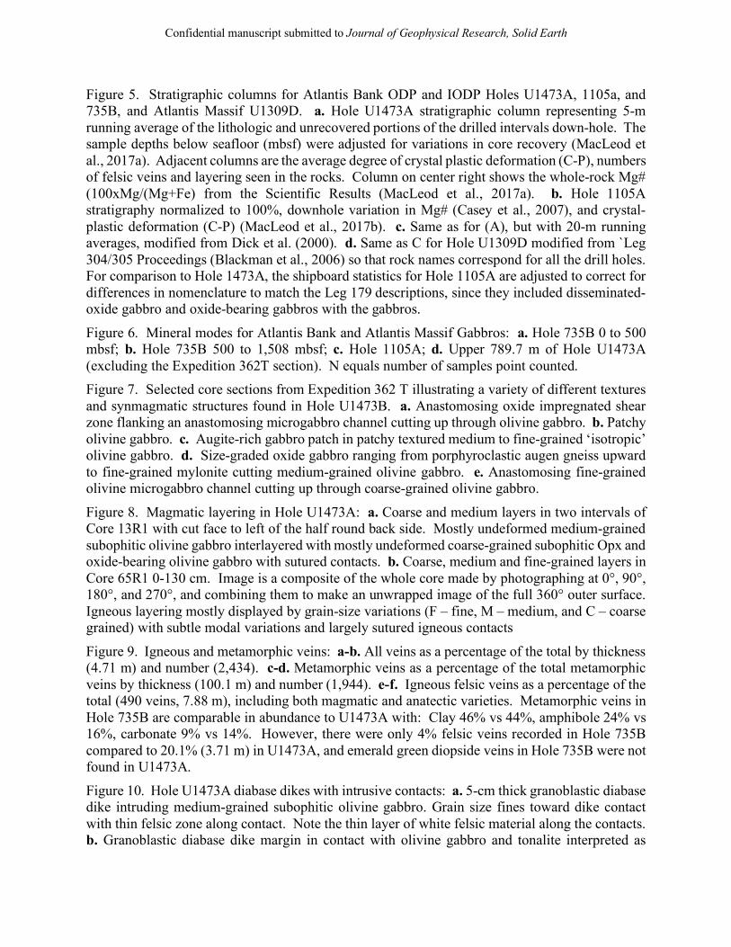
Confidential manuscript submitted to Journal of Geophysical Research, Solid Earth
Figure 5. Stratigraphic columns for Atlantis Bank ODP and IODP Holes U1473A, 1105a, and 735B, and Atlantis Massif U1309D. a. Hole U1473A stratigraphic column representing 5-m running average of the lithologic and unrecovered portions of the drilled intervals down-hole. The sample depths below seafloor (mbsf) were adjusted for variations in core recovery (MacLeod et al., 2017a). Adjacent columns are the average degree of crystal plastic deformation (C-P), numbers of felsic veins and layering seen in the rocks. Column on center right shows the whole-rock Mg# (100xMg/(Mg+Fe) from the Scientific Results (MacLeod et al., 2017a). b. Hole 1105A stratigraphy normalized to 100%, downhole variation in Mg# (Casey et al., 2007), and crystal-plastic deformation (C-P) (MacLeod et al., 2017b). c. Same as for (A), but with 20-m running averages, modified from Dick et al. (2000). d. Same as C for Hole U1309D modified from `Leg 304/305 Proceedings (Blackman et al., 2006) so that rock names correspond for all the drill holes. For comparison to Hole 1473A, the shipboard statistics for Hole 1105A are adjusted to correct for differences in nomenclature to match the Leg 179 descriptions, since they included disseminated-oxide gabbro and oxide-bearing gabbros with the gabbros.
Figure 6. Mineral modes for Atlantis Bank and Atlantis Massif Gabbros: a. Hole 735B 0 to 500 mbsf; b. Hole 735B 500 to 1,508 mbsf; c. Hole 1105A; d. Upper 789.7 m of Hole U1473A (excluding the Expedition 362T section). N equals number of samples point counted. Figure 7. Selected core sections from Expedition 362 T illustrating a variety of different textures and synmagmatic structures found in Hole U1473B. a. Anastomosing oxide impregnated shear zone flanking an anastomosing microgabbro channel cutting up through olivine gabbro. b. Patchy olivine gabbro. c. Augite-rich gabbro patch in patchy textured medium to fine-grained ‘isotropic’ olivine gabbro. d. Size-graded oxide gabbro ranging from porphyroclastic augen gneiss upward to fine-grained mylonite cutting medium-grained olivine gabbro. e. Anastomosing fine-grained olivine microgabbro channel cutting up through coarse-grained olivine gabbro.
Figure 8. Magmatic layering in Hole U1473A: a. Coarse and medium layers in two intervals of Core 13R1 with cut face to left of the half round back side. Mostly undeformed medium-grained subophitic olivine gabbro interlayered with mostly undeformed coarse-grained subophitic Opx and oxide-bearing olivine gabbro with sutured contacts. b. Coarse, medium and fine-grained layers in Core 65R1 0-130 cm. Image is a composite of the whole core made by photographing at 0°, 90°, 180°, and 270°, and combining them to make an unwrapped image of the full 360° outer surface. Igneous layering mostly displayed by grain-size variations (F – fine, M – medium, and C – coarse grained) with subtle modal variations and largely sutured igneous contacts
Figure 9. Igneous and metamorphic veins: a-b. All veins as a percentage of the total by thickness (4.71 m) and number (2,434). c-d. Metamorphic veins as a percentage of the total metamorphic veins by thickness (100.1 m) and number (1,944). e-f. Igneous felsic veins as a percentage of the total (490 veins, 7.88 m), including both magmatic and anatectic varieties. Metamorphic veins in Hole 735B are comparable in abundance to U1473A with: Clay 46% vs 44%, amphibole 24% vs 16%, carbonate 9% vs 14%. However, there were only 4% felsic veins recorded in Hole 735B compared to 20.1% (3.71 m) in U1473A, and emerald green diopside veins in Hole 735B were not found in U1473A.
Figure 10. Hole U1473A diabase dikes with intrusive contacts: a. 5-cm thick granoblastic diabase dike intruding medium-grained subophitic olivine gabbro. Grain size fines toward dike contact with thin felsic zone along contact. Note the thin layer of white felsic material along the contacts. b. Granoblastic diabase dike margin in contact with olivine gabbro and tonalite interpreted as

Confidential manuscript submitted to Journal of Geophysical Research, Solid Earth
contact anatexis of the gabbro, with photomicrograph in cross polars of the tonalite-diabase contact. c. Granoblastic diabase in ragged reacted contact with gabbro. Note what appears to be a partially assimilated gabbro patch in the diabase in the plane-polarized light microphotograph where the gabbro and the diabase are in contact. Note that clinopyroxene is replaced by brown amphibole in the crystallization sequence, likely due to diffusion of water from the gabbro into the dike.
Figure 11. Geochemistry of rocks recovered, Hole U1473A. a. Mg# vs. Ca#. Note that the higher Ca# of the 1473A gabbros is due to preferential dissolution of plagioclase in the oxide gabbros during melt rock reaction and/or excess Cpx due to melt rock reaction. b. Mg# vs. Ni. C. Mg vs. Y. D. Mg# vs. Cr. In each plot the most primitive rocks have the highest Mg#, Ca#, and Ni and Cr content and the lowest Y. Compositional data for rocks recovered from Holes 735B and 1105A are shown for comparison (Shipboard Scientific Party, 1999a; Casey et al., 2007).
Figure 12. Downhole variations in structure averaged per 10 meters in Hole U1473A: a. CPF intensity. Grey: interval fabric intensities representing lengths of core with relatively uniform fabric (i.e., orientation and intensity). Interval lengths vary from <1 cm to several meters in length. Black: running average, length weighted over 5 intervals (spreadsheet cells). CPF intensity: 0-undeformed, 1-foliated, 2-porphyroclastic, 3-protomylonite, 4-mylonite, 5-ultramylonite. b. Whole round magnetic susceptibility. c. Crystal-plastic foliation dips. d. CPF-shear sense. Cores oriented with the predominant foliation dipping to the left so a dextral shear sense is most common. e. Fault rock intensity: 1-minor fractures; 2-moderate fracturing; 3-incipient breccia; 4-fault breccia; 5-cataclasite. F. Fracture density: 1-one fracture per 10 cm; 2-two to five; 3 – greater than 5. Intensity and density are 11-cell (10 cm/cell) running averages. Grey bars indicate the seven major fault systems. Figure 13. Downhole variations in Hole U1473A for metamorphic vein density, mineral frequency per 10 m, and 11 point running average for fracture density. a. Metamorphic vein density per 10 cm: 0 — none; 1 — <1; 2 — 1-5; 3 — 5-10; 4 —1-20; 5 — >20. Black curve is an 11-point running average for vein density. b. amphibole, c. clay, and d. carbonate vein frequency per 10 m.
Figure 14. Downhole variations in alteration intensity, reddish clay after olivine (Ol), Alteration intensity is the sum of several processes. Plagioclase alteration, for example, includes dynamic recrystallized Pl neoblasts and albitic plagioclase due to hydrothermal alteration, which cannot be confidently separated macroscopically. Almost all of Hole U1473A has undergone significant dynamic or hydrothermal recrystallization. Alteration intensity: 0 - <3%; 1 - 3-9%; 2 - 10-29%; 3 - 30-59%; 4 - 60-90%; 5 - >90%.
Figure 16. Hole U1473A metamorphic veins: a. Compound amphibole-clinozoisite vein cutting olivine gabbro with alteration corona extending into the fresh olivine gabbro replacing primary Cpx. b. Microphotograph of compound vein in ‘A’ in plane light consisting of brown and brown-green amphibole sub perpendicular to crystal-plastic foliation, split by a later clinozoisite vein. c. Parallel set of black amphibole veins, one ~5+ mm thick, consisting of mostly of brown and some brown-green amphibole. d. Greenschist facies assemblage in plane light of a felt mass of pale green actinolite and chlorite cutting plagioclase. e. Greenschist facies micro vein crosscutting plagioclase in olivine gabbro consisting of chlorite, zoisite, and actinolite crosscutting plagioclase. f. Yellowish clay microveins crosscutting plagioclase in olivine gabbro. g. Late calcite veins

Confidential manuscript submitted to Journal of Geophysical Research, Solid Earth
crosscutting a neoblastic domain of plagioclase, Cpx, and olivine in plastically deformed olivine gabbro.
Figure 16. Ternary plots showing phase relations with varying initial anorthite activity, and mineral modes for Atlantis Bank Hole 1473A, MARK Holes 921A to 923A at 23.5°N and Atlantis Massif Hole U1309D at 30°N on the Mid-Atlantic Ridge. a. Phase relations in the system CaO-Na2O-MgO-Al2O3-SiO2 modified from Biggar and Humphries {Biggar, 1981 #4155}. Grey arrows show the down- temperature paths for assimilation-fractional crystallization (AFC), and fractional crystallization (FC). Phase fields are labeled in green for the system CaO-MgO-Al2O3-SiO2. b. Modal proportions of Hole 1473A gabbros down to 790 mbsf. c. ODP Sites 921, 922, 923, Mid-Atlantic Ridge at 23°N, point count data from Cannat et al. {, 1995 #4822}. d. Hole U1309D, Atlantis Massif, Mid-Atlantic Ridge. Modal data filtered from point counts and visual estimates from Robinson et al. {, 1989 #2671}, Dick et al. {, 1999 #6012}, Pettigrew et al. {, 1999 #8384}, and MacLeod {, 2017 #8161}. Curved AFC paths are for the reaction:
L1 + Mg2SiO4 + CaAl2Si2O8 –> L2 + CaMgSi2O6 + NaAlSi3O8 + Oxide where moles Pl1 < Pl2 in the product, and Pl2 is more sodic as well as less in volume, while oxide precipitation increases silica in the melt leading to felsic vein formation. Figure 17. FeOtotal versus MgO in Hole U1473A gabbros regrouped to match the classification used for Atlantis Massif Hole U1309D. Fields for 1309D and the plot design are modified from Figure 3c of Godard et al. (2009). Thin black lines indicate constant molecular Mgx100/(Mg+Fe) ranging from 20 to 95. Variations of Fe–Mg compositions of olivine (OL), clinopyroxene (CPX) and plagioclase (PLAG) in Site U1309 gabbros are represented by thick dashed lines (OL, CPX) and a white rectangle (PLAG).

Confidential manuscript submitted to Journal of Geophysical Research, Solid Earth

Figure 1. Southwest Indian Ridge from 56° to 59°E showing Atlantis Bank and the Atlantis II Fracture Zone. Ridge segments are numbered following Hosford et al. (2003) and Baines et al. (2007), numbering east to west from the Gauss to the Atlantis II FZ, Atlantis II to the Novara FZ, and Novara to the Melville FZ. These segments correspond to segments 20a, 20b, 19, 18, and 17 of Cannat et al. (1999). Bathymetric data from {Mendel, 1997 #7780;Hosford, 2003 #6053;Baines, 2007 #6491}.

Figure 2. Geologic map of Atlantis Bank reproduced from Dick et al. (in submission, Progress in Earth and Planetary Science).

Figure 3. East-West cross-section of Atlantis Bank through Hole 735B based on the seafloor mapping and ODP and IODP drill cores. Subsurface geology at depth including dunite and basal cumulates, and the location of crust-mantle boundary are by inference. Heavy black lines show the Moho reflectors (Minshull et al., 1998; Muller et al., 2000; Muller et al., 1997). The gaps are attributed to the geometry of OBS emplacement and ray tracing. Projected onto this line, ROV & submersible dives, over-the-side rock drills, Hole 735B and dredges show continuous gabbro outcrop, locally covered by a thin detachment fault zone assemblage of talc-serpentine schist, diabase cataclasite and weathered pillow basalt and cataclasized gabbro mylonites where the original fault surface is uneroded. Best guess model for Moho and crust-mantle boundary are shown - but only drilling will tell. Lithologic units in the gabbro massif are identified by color in the inset for two dives. Dive profiles and alternate interpretations C and D are reproduced from Dick et al. (2019), while the lithostratigraphic columns are modified from Dick et al. (1999).

Figure 4. Atlantis Bank tectonic model from Dick et al.(2019). A. N-S cross section of the paleo-rift valley and opposing outside and inside-corner highs ~15 km east of the ridge-transform intersection. The gabbro above the melt lens migrates diapirically as a mush, by crystal-plastic flow at low melt %, and then by solid-state crystal-plastic deformation. Small higher level intrusions crosscut the fabric of the rising gabbro as an ongoing process. Heavy red line shows the detachment fault cutting through the dike-gabbro transition into partially molten gabbro. It extends beneath the rift valley, resulting in fault capture and asymmetric spreading of the lower crust to the south. Late, upwardly and laterally compacting interstitial melt creates an oxide-gabbro rich zone in the upper 500-m of the lower crust, and migrates into the detachment fault zone to form an oxide-gabbro rich mylonite that extends over the core complex. Grey arrows show lithospheric flow, which extends up to the dike-gabbro transition. Fields for brittle, crystal-plastic, and crystal mush deformation and flow are separated by the thin dashed lines. Note that the crystal-plastic field overlaps the partially molten region at low melt %. B. 3-D south looking cartoon at right angles to cross section ‘A’. Late E-W brittle faulting during lithospheric rollover and mass wasting are excluded for simplicity. The detachment footwall curves smoothly downward across the gabbro-mantle contact to the transform floor, and from the inside corner high to its termination on the rift valley floor. Thus, the detachment fault termination (heavy red-dashed line) extends along the foot of the rift valley wall, then curves, evolving from a normal fault in the rift valley, to oblique slip, to strike slip at the base of the transform wall. The fault below the transform valley (heavy red line) then forms a branch of an active negative fault flower structure forming the plate boundary between the African and Antarctic Plates.


Figure 5. A. Hole U1473A stratigraphic column representing 5-m running average of the lithologic and unrecovered portions of the drilled intervals down-hole. The sample depths below seafloor (mbsf) were adjusted for variations in core recovery (MacLeod et al., 2017a). Adjacent columns are the average degree of crystal plastic deformation (C-P), numbers of felsic veins and layering seen in the rocks. Column on center right shows the whole-rock Mg# (100xMg/(Mg+Fe) from the Scientific Results (MacLeod et al., 2017a). B. Hole 1105A stratigraphy normalized to 100%, downhole variation in Mg# (Casey et al., 2007), and crystal-plastic deformation (C-P) (MacLeod et al., 2017b). C. Same as for (A), but with 20-m running averages, modified from Dick et al. (2000). D. Same as C for Hole U1309D modified from `Leg 304/305 Proceedings (Blackman et al., 2006) so that rock names correspond for all the drill holes. For comparison to Hole 1473A, the shipboard statistics for Hole 1105A are adjusted to correct for differences in nomenclature to match the Leg 179 descriptions, since they included disseminated-oxide gabbro and oxide-bearing gabbros with the gabbros.

Figure 6. Mineral modes for Atlantis Bank and Atlantis Massif Gabbros: A. Hole 735B 0 to 500 mbsf; B. Hole 735B 500 to 1,508 mbsf; C. Hole 1105A; D. Upper 789.7 m of Hole U1473A (excluding the Expedition 362T section). N equals number of samples point counted.
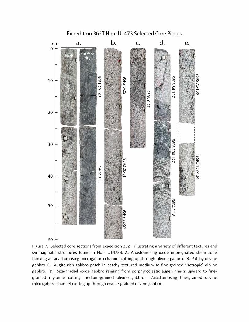
Figure 7. Selected core sections from Expedition 362 T illustrating a variety of different textures and synmagmatic structures found in Hole U1473B. A. Anastomosing oxide impregnated shear zone flanking an anastomosing microgabbro channel cutting up through olivine gabbro. B. Patchy olivine gabbro C. Augite-rich gabbro patch in patchy textured medium to fine-grained ‘isotropic’ olivine gabbro. D. Size-graded oxide gabbro ranging from porphyroclastic augen gneiss upward to fine-grained mylonite cutting medium-grained olivine gabbro. Anastomosing fine-grained olivine microgabbro channel cutting up through coarse-grained olivine gabbro.

Figure 8. Magmatic layering in Hole U1473A: A. Coarse and medium layers in two intervals of Core 13R1 with cut face to left of the half round back side. Mostly undeformed medium-grained subophitic olivine gabbro interlayered with mostly undeformed coarse-grained subophitic Opx and oxide-bearing olivine gabbro with sutured contacts. B. Coarse, medium and fine-grained layers in Core 65R1 0-130 cm. Image is a composite of the whole core made by photographing at 0°, 90°, 180°, and 270°, and combining them to make an unwrapped image of the full 360° outer surface. Igneous layering mostly displayed by grain-size variations (F – fine, M – medium, and C – coarse grained) with subtle modal variations and largely sutured igneous contacts

Figure 9. Igneous and metamorphic veins: A-B. All veins as a percentage of the total by thickness (4.71 m) and number (2,434). C-D. Metamorphic veins as a percentage of the total metamorphic veins by thickness (100.1 m) and number (1,944). E-F. Igneous felsic veins as a percentage of the total (490 veins, 7.88 m), including both magmatic and anatectic varieties. Metamorphic veins in Hole 735B are comparable in abundance to U1473A with: Clay 46% vs 44%, amphibole 24% vs 16%, carbonate 9% vs 14%. However, there were only 4% felsic veins recorded in Hole 735B compared to 20.1% (3.71 m) in U1473A, and emerald green diopside veins in Hole 735B were not found in U1473A.

Figure 10. Hole U1473A diabase dikes with intrusive contacts: A. 5-cm thick granoblastic diabase dike intruding medium-grained subophitic olivine gabbro. Grain size fines toward dike contact with thin felsic zone along contact. Note the thin layer of white felsic material along the contacts. B. Granoblastic diabase dike margin in contact with olivine gabbro and tonalite interpreted as contact anatexis of the gabbro, with photomicrograph in cross polars of the tonalite-diabase contact. C. Granoblastic diabase in ragged reacted contact with gabbro. Note what appears to be a partially assimilated gabbro patch in the diabase in the plane-polarized light microphotograph where the gabbro and the diabase are in contact. Note that clinopyroxene is replaced by brown amphibole in the crystallization sequence, likely due to diffusion of water from the gabbro into the dike.

Figure 11. Geochemistry of rocks recovered, Hole U1473A. A. Mg# vs. Ca#. Note that the higher Ca# of the 1473A gabbros is due to preferential dissolution of plagioclase in the oxide gabbros during melt rock reaction and/or excess Cpx due to melt rock reaction. B. Mg# vs. Ni. C. Mg vs. Y. D. Mg# vs. Cr. In each plot the most primitive rocks have the highest Mg#, Ca#, and Ni and Cr content and the lowest Y. Compositional data for rocks recovered from Holes 735B and 1105A are shown for comparison (Shipboard Scientific Party, 1999a; Casey et al., 2007).

Figure 12. Downhole variations in structure averaged per 10 meters in Hole U1473A: A. CPF intensity. Grey: interval fabric intensities representing lengths of core with relatively uniform fabric (i.e., orientation and intensity). Interval lengths vary from <1 cm to several meters in length. Black: running average, length weighted over 5 intervals (spreadsheet cells). CPF intensity: 0-undeformed, 1-foliated, 2-porphyroclastic, 3-protomylonite, 4-mylonite, 5-ultramylonite. B. Whole round magnetic susceptibility. C. Crystal-plastic foliation dips. D. CPF-shear sense. Cores oriented with the predominant foliation dipping to the left so a dextral shear sense is most common. E. Fault rock intensity: 1-minor fractures; 2-moderate fracturing; 3-incipient breccia; 4-fault breccia; 5-cataclasite. F. Fracture density: 1-one fracture per 10 cm; 2-two to five; 3 – greater than 5. Intensity and density are 11-cell (10 cm/cell) running averages. Grey bars indicate the seven major fault systems.

Figure 13. A. Metamorphic vein density per 10 cm: 0 - none; 1 = <1; 2 = 1 to 5; 3 = 5 to 10; 4 = 10 to 20; 5 = >20. Black curve is the 11-point running average, horizontal shaded bars are fault zone locations. B. amphibole, C. clay and D. carbonate vein frequency with depth, Hole U1473A E. Fracture density reproduced from Figure 8.
Faultzones
0 1 2 3 4 5
100
200
300
400
500
600
700
Total veindensity (m
Dep
th (m
bsf)
Drilled interval, 481.70-518.45 mbsf
0 20 40
Amphibole veinfrequency
0 20 40 60
Clay vein frequency
0 10 20 30 40
Carbonate veinfrequency
Fracturedensity
0 1 2 3
15 mbsf44
115
187
274
335
411-469??
a. b. c. d. e.
Number NumberNumberNumberGrade
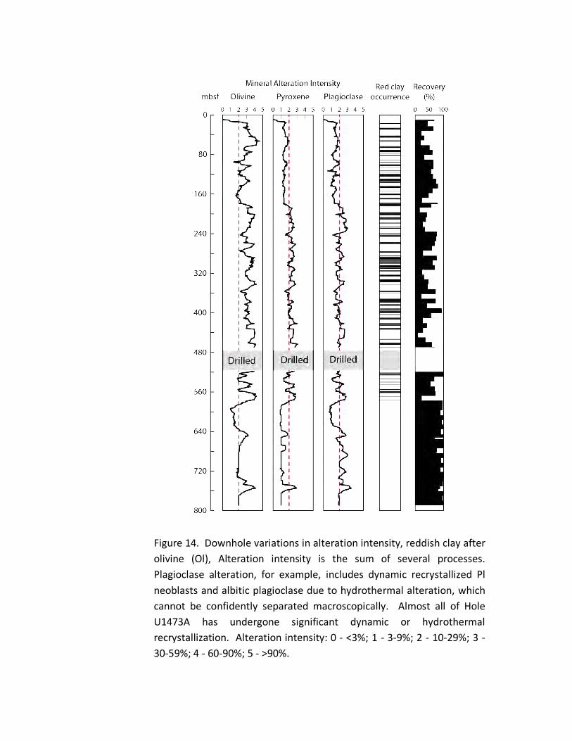
Figure 14. Downhole variations in alteration intensity, reddish clay after olivine (Ol), Alteration intensity is the sum of several processes. Plagioclase alteration, for example, includes dynamic recrystallized Pl neoblasts and albitic plagioclase due to hydrothermal alteration, which cannot be confidently separated macroscopically. Almost all of Hole U1473A has undergone significant dynamic or hydrothermal recrystallization. Alteration intensity: 0 - <3%; 1 - 3-9%; 2 - 10-29%; 3 - 30-59%; 4 - 60-90%; 5 - >90%.

Figure 15. Hole U1473A metamorphic veins: A. Compound amphibole-clinozoisite vein cutting olivine gabbro with alteration corona extending into the fresh olivine gabbro replacing primary Cpx. B. Microphotograph of compound vein in ‘A’ in plane light consisting of brown and brown-green amphibole sub perpendicular to crystal-plastic foliation, split by a later clinozoisite vein. C. Parallel set of black amphibole veins, one ~5+ mm thick, consisting of mostly of brown and some brown-green amphibole. D. Greenschist facies assemblage in plane light of a felt mass of pale green actinolite and chlorite cutting plagioclase. E. Greenschist facies micro vein crosscutting plagioclase in olivine gabbro consisting of chlorite, zoisite, and actinolite crosscutting plagioclase. F. Yellowish clay microveins crosscutting plagioclase in olivine gabbro. G. Late calcite veins crosscutting a neoblastic domain of plagioclase, Cpx, and olivine in plastically deformed olivine gabbro.

Figure 16. A. Phase relations in the system CaO-Na2O-MgO-Al2O3-SiO2 modified from Biggar and Humphries {Biggar, 1981 #4155}. Grey arrows show the down- temperature paths for assimilation-fractional crystallization (AFC), and fractional crystallization (FC). Phase fields are labeled in green for the system CaO-MgO-Al2O3-SiO2. B. Modal proportions of Hole 1473A gabbros down to 790 mbsf. C. ODP Sites 921, 922, 923, Mid-Atlantic Ridge at 23°N, point count data from Cannat et al. {, 1995 #4822}. D. Hole U1309D, Atlantis Massif, Mid-Atlantic Ridge. Modal data filtered from point counts and visual estimates from Robinson et al. {, 1989 #2671}, Dick et al. {, 1999 #6012}, Pettigrew et al. {, 1999 #8384}, and MacLeod {, 2017 #8161}. Curved AFC paths are for the reaction:
L1 + Mg2SiO4 + CaAl2Si2O8 –> L2 + CaMgSi2O6 + NaAlSi3O8 + Oxide
where moles Pl1 < Pl2 in the product, and Pl2 is more sodic as well as less in volume, while oxide precipitation increases silica in the melt leading to felsic vein formation.

Figure 17. FeOtotal versus MgO in Hole U1473A gabbros regrouped to match the classification used for Atlantis Massif Hole U1309D. Fields for 1309D and the plot design are modified from Figure 3c of Godard et al. (2009). Thin black lines indicate constant molecular Mgx100/(Mg+Fe) ranging from 20 to 95. Variations of Fe–Mg compositions of olivine (OL), clinopyroxene (CPX) and plagioclase (PLAG) in Site U1309 gabbros are represented by thick dashed lines (OL, CPX) and a white rectangle (PLAG).
1
JOURNAL OF GEOPHYSICAL RESEARCH
Supporting Information for
Dynamic accretion beneath a slow spreading ridge
segment: IODP Hole 1473A & the Atlantis Bank
Oceanic Core Complex
H.J.B. Dick1*, C.J. MacLeod2, P. Blum3, N. Abe4, D.K. Blackman5, J.A. Bowles6, M.J. Cheadle7, K. Cho8, J. Ciążela9, J.R. Deans10, V.P. Edgcomb1, C. Ferrando11, L. France12, B. Ghosh13, B. Ildefonse11, B. John7, M.A. Kendrick14, J. Koepke15, J.A.M. Leong16, C. Liu17, Q. Ma18, T. Morishita19, A. Morris20 J. H. Natland21, T. Nozaka22, O. Pluemper23, A. Sanfilippo24, J.B. Sylvan25, M.A. Tivey1, R. Tribuzio24, G. Viegas26
1 Dept. of Geology & Geophysics, Woods Hole Oceanographic Institution, Woods Hole MA, USA, 2 Dept. of Earth Sci., Cardiff University Cardiff Wales, United Kingdom 3 International Ocean Discovery Program, Texas A&M University, College Station TX, USA 4 Ocean Drilling Science, Japan Agency for Marine-Earth Sci. & Technology, Yokosuka Kanagawa, Japan
5 Scripps Institution of Oceanography, University of California, San Diego, La Jolla CA, USA 6 Dept. of Geosci., University of Wisconsin-Milwaukee, Milwaukee WI, USA 7 Dept. of Geology & Geophysics, University of Wyoming, Laramie WY, USA 8 Dept. of Environmental Exploration Engineering, Pukyong National University, Republic of Korea 9 Institute of Geology, Adam Mickiewicz University, Poznan, Poland 10 School of Biological, Environmental, and Earth Sci., University of Southern Mississippi, USA 11 Geosciences Montpellier, CNRS, University of Montpellier, Montpellier, France 12 Centre de Recherches Pétrographiques et Géochimiques, CNRS, Université de Lorraine, Nancy, France
13 Dept. of Geology, University of Calcutta, Kolkata, India 14 Research School of Earth Sci., The Australian National University, Acton, Australia 15 Institut fuer Mineralogie, University of Hannover, Hannover, Germany 16 School of Earth & Space Exploration, Arizona State University, Tempe AZ, USA 17 Institute of Geology & Geophysics, Chinese Academy of Sci., Beijing 100029, China 18 School of Ocean & Earth Sci., Tongji University, 1239 Siping Road, Shanghai, China, 19 Kanazawa University, College of Sci. & Engineering, Kanazawa, Ishikawa, Japan 20 School of Geography, Earth, & Environmental Sci., University of Plymouth, United Kingdom 21 Rosenstiel School of Marine & Atmospheric Sci., University of Miami, Miami FL, USA 22 Dept. of Earth Sci., Okayama University, Okayama, Japan 23 Department of Earth Sci., Utrecht University, Utrecht, Netherlands 24 Dipartimento di Scienze della Terra e dell’Ambiente - Università degli Studi di Pavia, , Pavia, Italy
25 Dept. of Oceanography, Texas A&M University, College Station TX, USA 26 Instituto de Geociências, Universidade de Brasília, Brasília, DF, Brazil

2
Corresponding author: Henry JB Dick ([email protected])
Contents of this file
Figures S1 to S6 Tables S1 to S2
Introduction
Supplemental data include six figures: S1 Images of representative felsic veins from Hole U1473A; S2 Images of representative felsic breccias; S3 Images of Hole U1473A cores showing typical rock fabrics; S4 Microphotographs of crystal-plastic deformation fabrics; S5 Downhole geophysical logs for Hole U1473A; S6 Lithostratigraphies of Holes 735B, 1105A, and U1473A. Also included are tables S1 Number and proportions of macroscopically estimated vein types in the Hole U1473A gabbros; S2 Location, depth of penetration, core recovery and units in lower crustal drill holes at slow and ultraslow spreading ridges.

3
Figure S1. Representative felsic veins from Hole U1473A: A. Undeformed diorite vein intruding mylonitic gabbro pseudomorphed and crosscut by amphibole veins, and photomicrograph in cross polars of the contact. Note the adjacent 2 mm thick parallel amphibole vein. B. Weakly deformed leucodiorite vein crosscutting altered gabbro mylonite with planar sutured contacts. Photomicrograph in cross polars showing minor deformation of the vein with plagioclase sub-grains, undulose extinction, and neoblasts. C. Heavily deformed felsic vein cutting a gabbro protomylonite with foliation sub parallel to the vein contacts. Note the reverse shear sense indicated by the rotated amphibole ‘fish’. D. Moderately deformed leucodiorite vein crosscutting a gabbro mylonite. Note that the center of the vein has been sheared and recrystallized with a dextral shear sense consistent with a normal fault.

4
Figure S2. Felsic breccias. A. Quartz diorite infiltrated and incorporated xenocrysts and clasts from host olivine gabbro. B. Quartz diorite invasive fill in semi-brittle pull-apart structure in olivine gabbro. C. Incipient leucodioritic magmatic breccia folded by a vertical shear band on left side of the core section. Red box outlines area of microphotograph in ‘D’. D. Clasts of plagioclase and Cpx in a fine-grained plagioclase matrix.
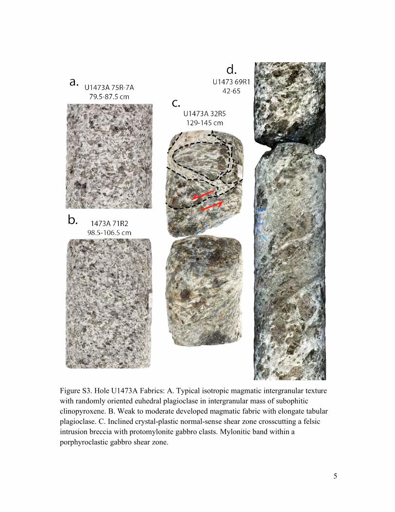
5
Figure S3. Hole U1473A Fabrics: A. Typical isotropic magmatic intergranular texture with randomly oriented euhedral plagioclase in intergranular mass of subophitic clinopyroxene. B. Weak to moderate developed magmatic fabric with elongate tabular plagioclase. C. Inclined crystal-plastic normal-sense shear zone crosscutting a felsic intrusion breccia with protomylonite gabbro clasts. Mylonitic band within a porphyroclastic gabbro shear zone.

6
Figure S4. Crystal-plastic deformation fabrics: Microphotographs A to C are in crossed polarizers, and D to F in plane polarized light. A and C are Olivine (Ol) gabbros with porphyroclastic fabric defined by clinopyroxene (Cpx), elongated olivine, and plagioclase (Pl) porphyroclasts immersed in a fine-grained recrystallized plagioclase matrix. Olivine contains numerous subgrain boundaries. B. Fine-grained mylonite consisting of a mixture of recrystallized plagioclase, clinopyroxene, amphibole (Am), and oxides (Ox). D. Clinopyroxene porphyroclast replaced by amphibole and rimmed by fine-grained recrystallized amphibole and oxide crystals in a disseminated-oxide gabbro layer. Clinopyroxene neoblast trail give a reversed shear sense. E. Fine-grained oxide concentrations and bands bordering an ultramylonite shear zone composed of recrystallized clinopyroxene, plagioclase, and brown amphibole cutting a weak to moderately recrystallized olivine gabbro. Footwall fabric asymmetry in the olivine gabbro gives a normal shear sense (red arrows). Locally a few clinopyroxene porphyroclasts are preserved. F. Porphyroclastic oxide gabbro with more diffusely distributed oxide and local oxide segregations that enclose pyroxene neoblasts. Oxide also decorates cracks in the plagioclase and grain boundaries.

7
Figure S5. A. Downhole logs (unprocessed data). Triple combo (blue) and FMS (red) caliper logs. Running 2.25 m average density, VS, and resistivity (blue – mid-range penetration, black — deepest penetration) logs. B. Expedition 362T logs for cores U1473A 93R through 96R: whole-round magnetic susceptibility, section half magnetic susceptibility, and natural gamma radiation log (primarily due to the radioactive decay of 40K and the decay of isotopes in the decay series of 238U and 232Th).

8
Figure S6. Lithostratigraphy, 100xMg/(Mg+Fe), igneous layer locations, amphibole vein frequency, and crystal plastic deformation versus depth for ODP Holes 735B and 1105A, and IODP Hole 1473A, modified from the Expedition 360 Proceedings {MacLeod, 2017 #8161} and the Leg 176 Initial Reports {Dick, 1999 #6012}. Lithostratigraphic column for Hole U1473A shows recovered lithologies as a percentage of the cored interval, due to the non-uniform recovery down the hole. Lithostratigraphic columns for Holes 735B and 1105A, where the recovery was high, simply plot the recovered lithologies per interval normalized to 100%. Note that column for Hole 1105A are 10-m running averages, and amphibole vein abundance for Hole 735B is a 20-m running average as a percent of the core, whereas for Holes 1105A and U1473A it is the number of veins per 10-m interval.

9
Tables
Table S1. Hole U1473A macroscopically estimated vein types
Vein type Number Vein (%)
Thickness (cm)
Thickness (%)
All veins (metamorphic and magmatic):
Felsic 490 20.1 371.3 78.8 White clay 945 38.8 23.4 5 Amphibole 390 16 47.2 10 Carbonate 349 14.3 13.4 2.8
Brown clay 121 5 6.5 1.4 Carbonate clay 56 2.3 2.2 0.5
Chlorite 37 1.5 4.1 0.9 Plagioclase 27 1.1 1.8 0.4 Plagioclase
chlorite 7 0.3 0.7 0.1 Other 12 0.5 0.7 0.1
Totals: 2434 100 471.4 100 Metamorphic veins:
White clay 945 48.6 23.4 23.4 Amphibole 390 20.1 47.2 47.2 Carbonate 349 18 13.4 13.4
Brown clay 121 6.2 6.5 6.5 Carbonate clay 56 2.9 2.2 2.1
Chlorite 37 1.9 4.1 4.1 Plagioclase 27 1.4 1.8 1.8 Plagioclase
chlorite 7 0.4 0.7 0.7 Other 12 0.6 0.7 0.6
Totals: 1944 100 100 100
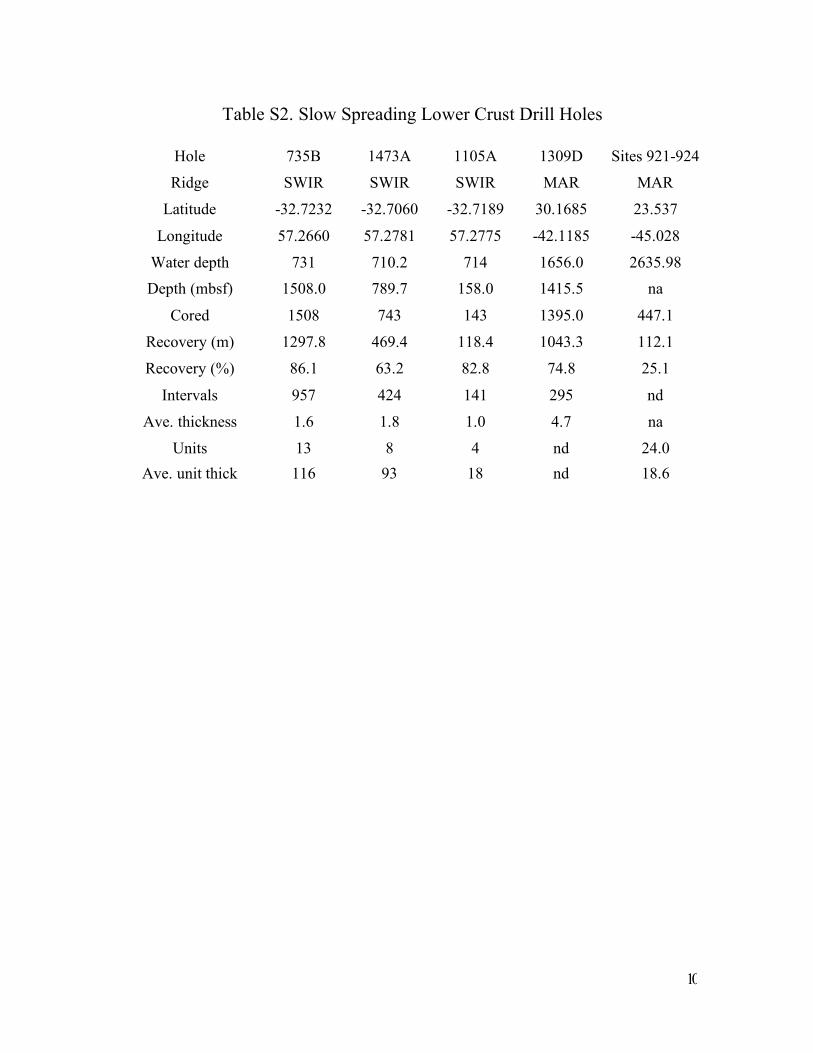
10
Table S2. Slow Spreading Lower Crust Drill Holes
Hole
Ridge
735B
SWIR
1473A
SWIR
1105A
SWIR
1309D
MAR
Sites 921-924
MAR
Latitude -32.7232 -32.7060 -32.7189 30.1685 23.537
Longitude 57.2660 57.2781 57.2775 -42.1185 -45.028
Water depth 731 710.2 714 1656.0 2635.98 Depth (mbsf) 1508.0 789.7 158.0 1415.5 na
Cored 1508 743 143 1395.0 447.1
Recovery (m) 1297.8 469.4 118.4 1043.3 112.1
Recovery (%) 86.1 63.2 82.8 74.8 25.1
Intervals 957 424 141 295 nd
Ave. thickness 1.6 1.8 1.0 4.7 na
Units 13 8 4 nd 24.0 Ave. unit thick 116 93 18 nd 18.6