agso eco 1993/5 • /o • suey o e ook ige a eig-meies • acue ... · • wie a as a come oogay i...
TRANSCRIPT

•••• AUSTRALIAN GEOLOGICAL SURVEY ORGANISATION
• Marine Geoscience and Petroleum Geology Program••••
• AGSO Record 1993/85••• N/O L'Atalante swath-bathymetry and geophysical• survey of the Norfolk Ridge and Vening-Meinesz• Fracture Zone, October 1993••• by
•• 1̂11111111011111111111111111111
DEPARTMENT OF PRIMARY INDUSTRIES AND ENERGY
Minister for Resources: Hon. Michael Lee, MPSecretary: Greg Taylor
AUSTRALIAN GEOLOGICAL SURVEY ORGANISATION
Executive Director: Harvey Jacka
C Commonwealth of Australia
ISSN: 1039-0073
ISBN: 0 642 19886 1
This work is copyright. Apart from any fair dealings for the purposes of study,research, criticism or review, as permitted under the Copyright Act, no part may bereproduced by any process without written permission. Copyright is the responsibilityof the Executive Director, Australian Geological Survey Organisation. Inquiriesshould be directed to the Principal Information Officer, Australian GeologicalSurvey Organisation, GPO Box 378, Canberra City, ACT, 2601.

•••
CONTENTS ^Page
•SUMMARY^ 4
•• INTRODUCTION^ 5
• L'ATALANTE AND ITS SURVEY SYSTEMS^ 5
• PHYSIOGRAPHY OF THE NORFOLK RIDGE SYSTEM^6
• REGIONAL GEOLOGICAL SETTING AND TECTONICS^6
SCIENTIFIC PROGRAM AND DATA ACQUIRED^ 8
•^CRUISE NARRATIVE^ 8
• PRELIMINARY RESULTS^ 12
• ACKNOWLEDGEMENTS^ 15
• REFERENCES^ 16••••••••••••••••
1CI) Australian Geological Survey Organisation, 1993

•••
FIGURES
• Page
• 1. TRANSNOR survey location map, regional structural elements and bathymetry (basemap after Kroenke eta!., 1983; bathymetry in metres)^ 18
2. Australian seabed boundaries in the Norfolk and Lord Howe Islands region (afterSymonds and Willcox, 1989)^ 19
3. N/0 L'Atalante and the sonar beam configuration of the SIMRAD Dual EM12 swath-mapping system^ 20
4.^EM12D characteristics, (a) deep mode performance for the 5 coverage sectors, and• (b) swath coverage versus water depth^ 21
• 5. L'Atalante time-annotated track map, TRANSNOR survey of the Norfolk Ridge and
•^Vening-Meinesz Fracture Zone^ 22
• 6.^Survey lines (TN01-17) and way-point (A-T) location map, TRANSNOR cruise ....23
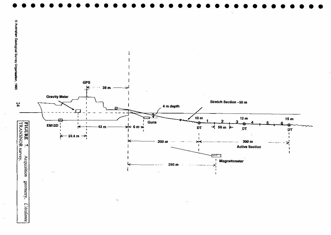
•^7. Acquisition geometry, L'Atalante TRANSNOR survey^ 24
•^8.^Canyon development on the northern Norfolk Ridge (location in Figure 1), EM12D• bathymetry contours^ 25
• 9.^Volcanic edifices on the central Norfolk Ridge SSW of Norfolk Island (location in
•^Figure 1), EM12D bathymetry contours^ 26
• 10. Detached ?continental block adjacent to the Vening-Meinesz Fracture Zone, ReingaRidge (location in Figure 1) - EM12D bathymetry contours^27
11. Preliminary EM12D acoustic image of the Taranui Gap / Reinga Ridge area, linesTN04-08 (location in Figure 1)^ 28
•12. Prominent angular unconformity above a thick disturbed sedimentary succession
• (total section >1.8 s twt), central Norfolk Ridge (location in Figure 1) - line TNO2
•seismic section^ 29
• 13. Thick (>1.5 s twt) sedimentary section and ?volcanics beneath the central NorfolkRidge (location in Figure 1), line TNO2 seismic section^ 30
14. Thick (>2.0 s twt) , mildly-moderately deformed sedimentary section west of thesouthern Norfolk Ridge (location in Figure 1), line TNO2 seismic section^31
2
•••
••
••
• © Australian Geological Survey Organisation, 1993
0

•
•
• 15. Strongly deformed sedimentary section (>1.8 s twt thick) beneath the Taranui Gapadjacent to the northern Wanganella Ridge (location in Figure 1), line TNO3 seismic
• section^ 32•
16. Highly faulted and folded sedimentary section in the Taranui Gap adjacent to the• Norfolk (extreme southern)/Reinga Ridge (location in Figure 1), line TNO5 seismic
section^ 33•
• 17. Thick (>1.7 s twt), structurally-disturbed pile of sediment overlying ?volcanicbasement at the southern margin of the South Norfolk Basin (location in Figure 1),
• line TNO9 seismic section^ 34
•
•
•
APPENDICES
Page
• 1. Shipboard personnel^ 35
2. Information on L'Atalante^ 35
3. SIMRAD EM12D multibearn echo-sounder, technical details and characteristics ^36
4. Line designations and approximate lengths^ 38
5. Survey way-points^ 39• 6. Scientific and navigation equipment^ 40• 7. Geophysical acquisition parameters^ 41
8. File structures, (a) navigation and (b) non-seismic (including gravity and magnetics)• data^ 42
•
© Australian Geological Survey Organisation, 19933

•••• SUMMARY•
The Norfolk Ridge and Vening-Meinesz Fracture Zone were surveyed by the French• oceanographic research vessel N/O L'Atalante using wide-swath seafloor mapping and
•geophysical techniques. The survey was conducted during 24-30 October 1993 while theship was in transit between Noumea (New Caledonia) and Auckland (New Zealand). The
• objective was to achieve a better understanding of the structural architecture and tectonicevolution of these major, poorly-known submarine features.
•L'Atalante is a modern 85-m multi-purpose research vessel fitted with advanced technology
• survey equipment and computer facilities. The ship is owned by the Institut Francais de
• Recherche pour l'Exploitation de la Mer (IFREMER). It is equipped with a SIMRAD DualEM12 (EM12D) multi-beam 13 kHz echo-sounder system. This system maps bathymetryand produces acoustic images of the seafloor at a ship's speed of up to 10 knots or more.The swath width is —7 times water depth; the maximum effective coverage in deep water
• (several kilometres or more) is about 20 km.
Approximately 2200 km of high-quality data were recorded along the western flank of theNorfolk Ridge and in a criss-cross pattern over the Vening-Meinesz Fracture Zone. Thedata acquired included EM12D bathymetry and images, 6-channel airgun reflectionseismic, 3.5 kHz high resolution seismic, gravity and magnetics.
The survey showed that much of the western Norfolk Ridge is of uneven to ruggedtopography. The relief is due to canyon incision (often to a depth of several hundredmetres), seafloor volcanism and widespread, relatively young faulting that approaches orintersects the seabed. These faults are mostly small-scale and of steep dip. Locally, someconsistency in structural orientation is observed. Seafloor structures trend mainly in therange southwest to northwest.
Volcanic submarine terrain is most evident in the area adjacent to the Pliocene volcanicNorfolk and Philip Islands. The submarine volcanic cones and edifices are mainly 100-600
• m high and 0.5-4 km across.
• Observed sediment thickness on the Norfolk Ridge is typically 1.0-1.4 s twt; at least 2.0 stwt of sedimentary section is present in places. The section has been affected to varying
• degrees by faulting and folding.
• The seafloor topography at the southern end of the Norfolk Ridge and along the Vening-• Meinesz Fracture Zone is of extremely high relief (several thousand metres), with crustal
blocks and ridges rising steeply above adjacent deep and relatively flat-floored troughs and• basins. The structural grain trends northwest in the direction of the Fracture Zone. Large
•blocks of ?continental crust at the southwest margin of the South Norfolk Basin may havebecome detached by transform motion during opening of the basin. The Taranui Gap is
• underlain by a thick (at least 2.0 s twt) pile of sediment strongly deformed by ?Neogenetranspressional wrenching.
•
4• © Australian Geological Survey Organisation, 1993

•••••
In October 1993, the Norfolk Ridge and Vening-Meinesz Fracture Zone (Figure 1) were• surveyed by the French oceanographic research vessel (navire oceanographic) N/O
• L'Atalante of IFREMER (Institut Francais de Recherche pour l'Exploitation de la Mer).The swath-bathymetry and geophysical survey, named TRANSNOR, was of one week
• duration. The ship's complement of 39 included 4 marine geoscientists (Appendix 1). Theship left Noumea on Sunday 24 October 1993 and arrived in Auckland harbour on Saturday
• 30 October, at the end of the cruise. The survey work was undertaken in the Exclusive
•Economic Zones (EEZs) of France, Australia and New Zealand (Figure 2).
• The scientific program developed from a proposal by cruise leader, Jean Mascle ofLaboratoire de Geodynamique Sous-marine (Villefranche-sur-Mer), to utilise a Noumea-
• Auckland transit of the ship to map geological structure on the western flank of the Norfolk
•Ridge and along the Vening-Meinesz Fracture Zone with the aim of achieving a betterunderstanding of the structural architecture and tectonic evolution of these major
• submarine features.
0^The transit ex-Noumea followed the successful conclusion of a series of major surveys inthe Fiji/SolomonsNanuatu area (including SOPACMAPS for the South Pacific Applied
• Geoscience Commission). The port call in Auckland was scheduled for the start of111^GEODYNZ, a 5-week France - New Zealand co-operative program in waters adjacent to
New Zealand. This is to be followed by a 4-week survey of the mid-ocean ridge south of• New Zealand (PACANTARCTIC). In mid-January 1994, the ship is scheduled to begin a
major 6-week, AGSO-directed survey of the transform margin to the west and southwest of• Tasmania (AGSO Project 121.44).
The role of the author on this cruise was to, (i) participate in and contribute to the scientific• program, (ii) act as Australian representative and ensure that copies of data collected in
Australian waters were obtained, and (iii) become familiar with the swath-mapping and• geophysical systems aboard L'Atalante so that the forthcoming AGSO survey off Tasmania
• could be planned and executed in the most efficient and effective manner.
• This Record is a cruise report on the TRANSNOR survey. It provides backgroundinformation, an account of the survey operations and details of scientific data collected.
• Though some preliminary results are presented in this report, results of detailed analysis
• and interpretation of the data will be left to future publications.
••• L'Atalante (Figure 3, Appendix 2) is a modern 85-metre multi-purpose research vessel. It
was launched in 1990 and replaces the Jean Charcot. The laboratories onboard contain a• massive array of scientific equipment and computer facilities for acquiring, processing,
storing and displaying a wide range of geoscientific and oceanographic data. The ship has• the capability of launching and operating manned submersibles, such as Nautile, in water
•5
• © Australian Geological Survey Organisation, 1993
•
INTRODUCTION
•
L'ATALANTE AND ITS SURVEY SYSTEMS

•^depths up to 6000 m. L'Atalante was specifically built for high-technology seafloor
Omapping, and is equipped with the advanced SIMRAD Dual EM 12 multibeam echo-sounder (Figure 3, Appendix 3). This system maps bathymetry and acoustic reflectivity of
• the seafloor at a ship's speed of up to 1 0 knots or more. The swath width is —7 times waterdepth; the maximum effective coverage in deep water (several kilometres or more) is about
• 20 km (Figure 4).
• PHYSIOGRAPHY OF THE NORFOLK RIDGE SYSTEM
O The main structural elements and bathymetry of the region between New Caledonia and theNorth Island of New Zealand are indicated in Figure 1.
• The Norfolk Ridge system is a complex, elevated seafloor feature that extends from NewCaledonia to the northern tip of New Zealand.
The northern, north-trending segment . is the Norfolk Ridge (Figure 1). It is about 1000 km• long, about 70 km wide, steep-sided and with a crestal depth mainly in the range 500-1500
O m. There is a slight westward offset in the ridge just north of Norfolk and Philip Islands,located on the central portion of the ridge. These islands are the only subaerial parts of the
• ridge system. The Norfolk Ridge is flanked by the New Caledonia Basin to the west andthe North and South Norfolk Basins to the east. These basins are all about 3500-4000 mdeep.
• The southern, northwest-trending segment of the Norfolk Ridge system is about 250 km• wide and has a complex topography. It includes three main ridges - the West Norfolk
Ridge, the central Wanganella Ridge and the eastern Norfolk-Reinga-South Maria Ridge0^system. A 2000-m deep bathymetric trough, the Taranui Gap (or Sea Valley) separates the
•Wanganella and Norfolk/Reinga Ridges. The northeastern side of the Norfolk-Reinga-South Maria Ridge system slopes steeply into the South Norfolk Basin from water depths
• of less than 500 m to more than 3500 m. The Vening-Meinesz Fracture Zone (Figure 1) islocated along this northwest-trending ridge/basin margin.
• REGIONAL GEOLOGICAL SETTING AND TECTONICS•
The tectonic development of the New Caledonia - Norfolk Ridge - New Zealand region ofthe southwest Pacific has been discussed by Burns and Andrews (1973), Willcox et al.
•(1980), Ballance et al. (1982), Kroenke (1984), Eade (1988), Spärli and Ballance (1989)and Symonds and Colwell (1992). Results of early seismic surveys across the southern
• Norfolk Ridge system are outlined by Davey (1977). Plate reconstructions of the region forthe Cretaceous-Cainozoic have been made by Kamp (1986), Walley and Ross (1991) and
• Walley (1992). The following account of the geology and evolution of the region is largely
•taken from the last two publications.
• In the Early Cretaceous, prior to the breakup of eastern Gondwana, the New Zealand - NewCaledonia region was part of a convergent margin. Most of the region was emergent at thistime. Extension at the eastern Gondwana margin began in the late Early Cretaceous, with
6© Australian Geological Survey Organisation, 1993

•••
•^widespread terrestrial sedimentation taking place. The New Caledonia Basin is believed to
•have opened in the mid Cretaceous (-95 Ma). Seafloor spreading in the Tasman Sea during
• the Late Cretaceous to early Eocene (-86-56 Ma) was accompanied by regional subsidence
• and transgression.
• Rifting and seafloor spreading of the eastern Australian margin during the Cretaceous hasrecently been interpreted in terms of a continental margin detachment model (Etheridge et
• al., 1989; Lister et al., 1991). The model implies that a detachment system underlies the
• whole region, with the Lord Howe Rise and Norfolk Ridge composed of variouslyextended upper continental crust and thinned lower crust / upper mantle. Small intervening
• basins such as the New Caledonia Basin may be in part floored by highly-thinned lowercontinental crust. The crustal thickness beneath the Norfolk Ridge is 21 km (Shor et al.,
• 1971), which is greater than for a volcanic arc and somewhat thinner than for typical
•continental crust. Based on crustal thickness, seismic character and magnetic signature,Eade (1988) concluded that the Norfolk Ridge is likely to be of continental or continental
• margin origin.
• Cessation of seafloor spreading in the New Caledonia Basin (perhaps coincident with
•Tasman Basin opening), may have led to onset of east-dipping subduction along thewestern side of the north Norfolk Ridge. Back-arc basins developed in New Caledonia and
• to the east of the Norfolk Ridge creating the North and South Norfolk Basins. In thisversion of events (Walley and Ross, 1991), the Vening-Meinesz Fracture Zone was a
• transform fault separating continental crust of the Reinga Ridge from newly formed
•oceanic crust of the South Norfolk Basin. Launay et al. (1982) and Eade (1988) suggest theNorth and South Norfolk Basins opened from —85-75 Ma. However, other interpretations -
• including that of Rigolot (1989) and CPCEMR (1991) - indicate an Eocene age, with theimplication that opening of these basins immediately followed the end of spreading in the
• Tasman.
East-dipping subduction resulted in opening of back-arc basins northeast of New Caledonia• between Early and late Middle Eocene. Convergence increased from late Middle Eocene to
Early Oligocene, and following a change in plate boundary configuration the marginalbasin development ceased and newly-formed oceanic crust was obducted from thenortheast onto New Caledonia (Brothers and Lillie, 1988). Transpression and associateddextral strike-slip movement along the western Norfolk Ridge is inferred (Rigolot, 1989).
•In the mid-Late Eocene (at the same time as oblique plate convergence was taking placealong the northern Norfolk Ridge), a zone of extension developed through western NewZealand, leading to the accumulation of coal measures in fault-controlled basins. This was
• followed by regional subsidence and transgression during the Oligocene.
The South Fiji Basin opened between 36-26 Ma (Malahoff et al., 1982) as a back-arc basinto an arc along either the Three Kings Rise (Kroenke and Eade, 1982) or the Colville-LauRidge. The Vening-Meinesz Fracture Zone would have been an active transform faultduring this tectonism.
The modern convergent Indo-Australian/Pacific plate boundary was established in NewZealand in the latest Oligocene / earliest Miocene (-23 Ma). At this time the Indo-
7© Australian Geological Survey Organisation, 1993

•••
••• Australian/Pacific plate boundary began to propagate through New Zealand as a
convergent boundary. Dextral shear between the two halves of the North Island linked intothe Vening-Meinesz Fracture Zone. The transpression resulted in southwest-directedophiolite obduction onto the North Island in the latest Oligocene - earliest Miocene(Brothers and Delaloye, 1982).
Norfolk and Philip Islands, on the central Norfolk Ridge, were formed by Pliocene• volcanic activity dated at 3.1-2.3 Ma (Jones and McDougall, 1973; Aziz-Ur Ralunan and
• McDougall, 1973).
•SCIENTIFIC PROGRAM AND DATA ACQUIRED
•Some modifications to the original cruise proposal were made in Noumea immediatelyprior to departure. Further minor modifications were made during the survey as new
• structural detail and trends were revealed, and because of survey time constraints.
The survey comprised 17 lines, TNO1 to TN17. A time-annotated track map is presented inFigure 5. Figure 6 shows the line locations and also the way-points used during the survey.Line and way-point details are provided in Appendix 4 and 5, respectively.
During the TRANSNOR survey, geophysical data were acquired concurrently with theEM12D swath-mapping data acquisition. These geophysical data comprised gravity,magnetics, 3.5 kHz echo-sounder profiles and 6-channel GI gun seismic. The seismic datawere digitally recorded and displayed on two strip-chart monitors (fast and slow). Surveyand navigation equipment details are provided in Appendix 6. Also provided are thegeophysical acquisition parameters (Appendix 7) and the acquisition geometry (Figure 7).
The EM12D data were acquired digitally on the ARCHIV system. Bathymetry contourmaps (25 m contour interval and 1:100,000 scale) were plotted automatically almost in realtime on a large Benson flat-bed plotter with a selection of coloured pens. The mainrecorder that displays the acoustic images was not operational on this cruise.
A total of approximately 2200 km of data (EM12D, gravity, magnetics, 3.5 kHz and airgmseismic) were collected during the cruise. Data quality was very good.
Digital navigation, EM12D, gravity, magnetics and airgun seismic data were madeavailable on 8 mm EXABYTE cartridge. The 6-channel airgun seismic data were in SEG-Y format. The gravity data are based on the IGSN 71 datum and normal gravity given bythe formula
GN = 978030 + 5186sin20 - 7sin22o mGal, where 0 = latitude.
CRUISE NARRATIVE
The time and nature of significant events that occurred during the cruise are indicatedbelow. Times and dates are in GMT (UTC), unless specifically shown as being local.
8© Australian Geological Survey Organisation, 1993
•••

•• 23 October
2300 L'Atalante left Noumea (1000 hrs local Friday 24 October)
• 24 October
0 0015 Ship passed through outer reef off Noumea0
0034 Start of line TN01; collecting gravity and EM12D data0
O0108 Magnetometer fish deployed
• 0345 Reduced speed for Sippican temperature profile; magnetometer retrieved fordeployment of the airguns
0
•0406 Guns deployed
O 0409 Deployment of streamer started
O 0426 Guns firing
0430 Increasing ship's speed and redeploying the magnetometer
0438 Start of line TNO2
•0442 Slowing to 6 knots to recover port gun (not firing)
• 0500 Recording with 1 gun
• 0551 Slowing down to redeploy gun
• 0602 Gun in the water•
0632 Slowing to 6 knots to recover port gun
0646 Recording with 1 gun
•
•0718 Port gun back in the water
• 0731 Both guns deployed and firing okay
• 1107 Changed seismic tape (now #2)
• 1744 Changed seismic tape (now #3)
2105 Reduced speed to 6 knots for Sippican temperature profile•
9© Australian Geological Survey Organisation, 1993

• [Weather conditions during day: SSE winds of 20 knots, seas moderate-rough]
• 25 October
• 0015 Changed seismic tape (now #4)
• 0647 Changed seismic tape (now #5)•
1314 Changed seismic tape (now #6)•
1800 West of Norfolk Island
• 1851 Slowing to 6 knots for Sippican measurement
• 1911 Speed back to normal
• 1942 Changed seismic tape (now #7)• 2325 Changed seismic tape (now #8)
•
•
[Weather conditions during day: SE winds — 20 knots at first, then dropping to —10 knotsand swinging to the east]
26 October
• 0543 Changed seismic tape (now #9)• 0744 End of line TNO2; changed seismic tape (now #10); start of TNO3•
1409 Changed seismic tape (now #11)•
• 1513 End of line TNO3; start of TNO4 (at 1517)
• 1743 End of line TN04; start of TNO5 (at 1745)
• 2006 End of line TN05; changed seismic tape (now #12); start of TNO6
• 2130 40+ knot winds; ship's speed down to about 7.5 knots•
2303 End of line TN06; start of TNO7 (at 2313)•
•[Weather conditions during day: the winds (from the NNE) increased in strength to over 40knots, very rough seas]
411/
10@ Australian Geological Survey Organisation, 1993

•27 October• 0244 Changed seismic tape (now #13)• 0527 Speed reduced to 6 knots for Sippican measurement
• 0706 End of line TN07; changed seismic tape (now #14); start of TNO8 (at 0713)
1003 End of line TN08; start of TNO9•
1252 End of line TN09; start of TN10 (at 1257)•
• 1341 Changed seismic tape (now #15)
• 1441 End of line TN10; start of TN11 (at 1446)
• 1939 Reducing speed to recover leaking port air-gun• 2000 Sippican measurement
2009 Changed seismic tape (now #16)•
• 2027 Reduced speed to 6 knots to redeploy port gun
• 2034 Port gun back in the water and ship's speed increased
• 2251 End of line TN11; changed seismic tape (now #17); start of TN12 (at 2258)
•
•
[Weather conditions during day: the NW-northerly winds gradually abated to —15 knots,seas were moderate-rough on a large swell]
28 October
• 0320 End of line TN12; changed seismic tape (now #18); start of TN13 (at 0325)
• 0932 End of line TN13; changed seismic tape (now #19); start of TN14 (at 0937)
• 1020 EM12D disk error; 15 minutes data lost•
1142 End of line TN14; start of TN15 (at 1146)•
•1248 End of line TN15; start of TN16 (at 1249)
• 1605 End of line TN16
• 1606 Changed seismic tape (now #20)
•11
• © Australian Geological Survey Organisation, 1993

••0
1617 Start of line TN17•
• 1857 Slowing to 6 knots for Sippican temperature profile
• 2241 Changed seismic tape (now #21)
• [Weather conditions during day: wind direction and strength were variable, but average
• speed was —15 knots from the NE; seas were rough on a large swell; rain squalls]
29 October•
• 0025 Stopped seismic acquisition to put new roll of paper in the fast recorder
• 0032 Again recording seismic
0040 Airguns not firing correctly, compressor problem
• 0110 Seismic restored
0246 Reducing speed prior to recovering the magnetometer and seismic gear•
•0300 Recovering outboard geophysical gear (magnetometer, airguns and seismicstreamer)
0319 All gear aboard, ship's speed increased (10+ knots); now acquiring only EM12D• and 3.5 kHz data as ship makes for Auckland
0700 Effective end of data acquisition
• L'Atalante docked in Auckland at 1100 hrs local on Saturday 30 October; customs
•clearance completed at 1200 hrs local.
PRELIMINARY RESULTS
Some preliminary results of the TRANSNOR survey are presented in this section. Theresults are based on the raw shipboard data (without post-processing), mainly the EM12D
• bathymetry contour plots and the seismic monitor records.
• The survey showed that much of the western Norfolk Ridge is of uneven to rugged
•topography. The relief is due to canyon incision, seafloor volcanism and widespread,relatively young faulting that approaches or intersects the seabed. These faults are mostly
• small-scale and of steep dip. No pronounced, consistent structural orientation is observedin the EM12D bathymetry contours on the Norfolk Ridge as a whole. Some local
•
•12
• © Australian Geological Survey Organisation, 1993

•
•
• consistency in structural orientation is observed, however. Seafloor structures trend mainly
•in the range southwest to northwest.
• Volcanic seafloor terrain is most evident in the area adjacent to Norfolk and Philip Islands.This suggests that most of the volcanic activity may be of Pliocene age.
•
1111^Observed sediment thickness on the Norfolk Ridge is typically 1.0-1.4 s twt; at least 2.0 stwt of sedimentary section is present in places. The section has been affected to varying
• degrees by faulting and folding.
An area of thick, relatively mildly deformed sedimentary section was encountered about
•250 km south of New Caledonia (at —24° 40' S). The section may be representative of thegeneral stratigraphy of the Norfolk Ridge. Here, an upper sequence of sub-horizontal beds
• overlies a prominent unconformity at —0.8 s twt sub-bottom that has small but pronouncedrelief. It may correspond to the regional late Oligocene unconformity observed in DSDP
• drilling (Burns and Andrews, 1973). The underlying sequence is about 1.0 s twt thick andconsists of sub-parallel to wavy beds that show some deformation. This is in turn underlainby a basal layer of chaotic reflection character. The boundary between the two layers is not
• sharp, but the change in reflection character is distinctive. No deeper, strong reflectors thatmight indicate 'true' basement are visible in the monitor data. The basal layer may consist
• of volcaniclastics that mask deep basement.
• The seafloor topography at the southern end of the Norfolk Ridge and along the Vening-411 Meinesz Fracture Zone is of extremely high relief (several thousand metres), with crustal
blocks and ridges rising steeply above adjacent deep and relatively flat-floored troughs andbasins. The structural grain trends northwest in the direction of the Fracture Zone. TheTaranui Gap is underlain by a thick (at least 2.0 s twt) pile of strongly deformed sediments.The style of deformation suggests wrenching (Symonds and Willcox, 1989), probably
• active during the Neogene when transpressive tectonism was active on the North Island(N.Z.).
•
• Specific examples of data collected during the cruise are presented in Figures 8-17 and
• discussed below.
Canyon development on the northern Norfolk Ridge. EM12D bathymetry contours (Figure ••
This area is of rugged topographic relief. Canyon development shows southwest andnorthwest trends into the New Caledonia Basin. The canyons are more than 20 km long
• and at least 450 m deep.••
Volcanic edifices on the central Norfolk Ridge SSW of Norfolk Island. EM12D bathymetrycontours (Figure 9)
•Numerous volcanic cones and other ?volcanic edifices rise from a seafloor that appears to
• be eroded and shows evidence of canyon cutting. The area has strong magnetic expression.
13110^@ Australian Geological Survey Organisation, 1993
1110

••••
The cones and edifices vary in size from 100-600 m high and 0.5-4 km across.
Detached ?continental block adjacent to the Vening-Meinesz Fracture Zone, Reinga Ridge• - EM12D bathymetry contours (Figure 10)
• The bathymety contours define a large (60 km long and 13 km wide) elevated block
• located just off the northwest-trending escarpment that marks the trace of the Vening-Meinesz Fracture Zone at the southwest margin of the South Norfolk Basin. The elongated
• block rises from the adjacent basin at 4000 m depth to less than 1000 m below sea-level.
• Local highs are located along the top of the escarpment, and these may be fault-bounded
• blocks or volcanic edifices.
• The large isolated block may represent a continental sliver that was torn from the ReingaRidge during transform faulting as the South Norfolk Basin opened.
• Preliminary EM12D acoustic image of the Taranui Gap / Reinga Ridge area. lines TN04-08 (Figure 11)
410^In this image areas of high acoustic backscatter (reflectivity) are shown dark and,conversely, areas of low backscatter are light toned.
•The image covers part of the detached block seen in the bathymetry of Figure 10. The light
• areas generally represent sedimented seafloor. Such areas include the floor of the deepsubmarine valley between the block and the Reinga Ridge escarpment, the floor of theSouth Norfolk Basin and much of the top of the Reinga Ridge. The steep escarpments and
• some areas of the seabed in the Taranui Gap are seen in the image as being dark andstructured. These dark areas probably represent exposed bedrock surfaces and perhapsvolcanics.
Prominent angular unconformity above a thick disturbed sedimentary succession (totalsection >1.8 s twt), central Norfolk Ridge - line TNO2 seismic section (Figure 12) •
•A major unconformity, 0.3-0.45 s twt sub-bottom, separates a thick lower sequence ofhummocky to sub-parallel reflection configuration from an upper sequence of strong
• parallel/sub-parallel reflectors. The upper sequence (?pelagics) consists of two units; theupper onlaps the lower. Minor steep faults extend upward to the shallower unconformity inthe upper sequence.
111• Thick (>1.5 s twt) sedimentary section and ?volcanics beneath the central Norfolk Ridge,
line TNO2 seismic section (Figure 13) •• The sedimentary section thickens locally in a broad trough located about 50 km northwest
of Norfolk Island. The southeastern flank of the trough appears to have been intruded by
14@ Australian Geological Survey Organisation, 1993

volcanics which have erupted onto the seafloor. Several prominent seismic horizons(including at least two angular unconformities) are present in the sedimentary section.
Thick (>2.0 s twt) . mildly-moderately deformed sedimentary section west of the southernNorfolk Ridge. line TNO2 seismic section. (Figure 14)
• The seismic section in Figure 14 is located NNW of the Taranui Gap and roughly along the• trend of this structure. A deep, narrow Geosat gravity low, which coincides with the
Taranui Gap, extends NNW to the location of the seismic section. The gravity low is a• reflection of the very thick sedimentary section observed here. The sediments at this
location are significantly less deformed than at the Gap (compare with Figures 15 and 16).• Diffraction hyperbolae deep in the section and to lesser extent within the mid section• suggest volcanics.
•Strongly deformed sedimentary section (>1.8 s twt thick) beneath the Taranui Gap
• adjacent to the northern Wanganella Ridge. line TNO3 seismic section (Figure 15)
The section shows complex folding and faulting. The deformed section is exposed on the• seafloor or covered by no more than a veneer of younger sediment. The rough seafloor is
probably a product of both structural deformation and submarine erosion.•
• Highly faulted and folded sedimentary section in the Taranui Gap adjacent to the Norfolk• (extreme southern)/Reinga Ridge. line TNO5 seismic section (Figure 16)
• The highly deformed sedimentary section exceeds 1.2 s twt in thickness. Tilted fault blocks
• are exposed on the seafloor. A thin layer (to —100 m) of relatively undeformed sedimentunconformably overlies the faulted/folded section, forming a blanket that smooths much of
• the pre-existing rough seafloor topography. The deformation is likely to be Neogene in age.
•
• Thick (> 1.7 s twt). structurally-disturbed pile of sediment overlying ?volcanic basement atthe southern margin of the South Norfolk Basin. line TNO9 seismic section (Figure 17)
Acoustic basement in this profile lies deeper than 6.5 s twt. Its indistinct upper surface• suggests it may be volcanic (?oceanic). The reflectors in the thick overlying sedimentary
• section are mainly discontinuous and hummocky, and show some faulting. The sectionprobably contains deep-sea fans and turbidites shed from the marginal escarpment
• immediately adjacent to the southwest.
•ACKNOWLEDGEMENTS
• The Captain, Jean Claude Gourmelon, officers and crew of the L'Atalante are thanked fortheir co-operation and skill in operational aspects of the scientific program. The ship's
• scientific and electronic technicians worked conscientiously to ensure that data acquisition
15© Australian Geological Survey Organisation, 1993
•• was maintained and that the data collected were of the highest quality possible; their very
willing help and support concerning technical matters is gratefully acknowledged.Christian Habault of the Ministere de la Recherche et de la Technologie (New Caledonia)
• is thanked for his generous assistance in Noumea. Phil Symonds of AGSO reviewed thedraft report.
• REFERENCES•
Aziz-Ur Rahman and McDougall, I., 1973 - Paleomagnetism and paleosecular variation in• lavas from Norfolk and Philip Islands, Southwest Pacific Ocean. Geophysical
Journal of the Royal Astronomical Society, 33, 141-145.Ballance, P.F., Pettinga, J.R. and Webb, C., 1982 - A model for the Cenozoic evolution of
• northern New Zealand and adjacent areas of the southwest Pacific. Tectonophysics,87, 37-48.
• Brothers, R.N. and Delaloye, M., 1982 - Obducted ophiolites of North Island, NewZealand: origin, age, emplacement and tectonic implications for Tertiary andQuaternary volcanicity. New Zealand Journal of Geology and Geophysics, 25, 257-
• 274.Brothers, R.N. and Lillie, A.R., 1988 - Regional geology of New Caledonia. In Nairn,
• A.E.M., Stehli, F.G. and Uyeda, S. (Editors), The Ocean Basins and Margins, Vol.7B: The Pacific Ocean. Plenum Press, N.Y. and London, 325-374.
• Burns, R.E. and Andrews, J.E., 1973 - Regional aspects of deep sea drilling in theSouthwest Pacific. In Burns, R.E., Andrews, J.E. et al., Initial Reports of the DeepSea Drilling Project, Volume 21, Washington (U.S. Government Printing Office),
i 897-906.QPCEMR (Circum-Pacific Council for Energy and Mineral Resources), 1991 - Tectonic
• map of the circum-Pacific region, southwest quadrant 1:10,000,000 (map CP-37).U.S. Geological Survey, Denver, Colorado.
Davey, F.J., 1977 - Marine seismic measurements in the New Zealand region. New Zealand• Journal of Geology and Geophysics, 20, 719-777.
Eade, J.V., 1988 - The Norfolk Ridge and its margins. In Nairn, A.E.M., Stehli, F.G. and• Uyeda, S. (Editors), The Ocean Basins and Margins, Vol. 7B: The Pacific Ocean.
•Plenum Press, New York and London, 303-324.
Etheridge, M.A., Symonds, P.A. and Lister, G.S., 1989 - Application of the detachment• model to reconstruction of conjugate passive margins. In Tankard, A.J. and Balkwill,
H.R. (Editors), Extensional Tectonics and Stratigraphy of the North AtlanticMargins. American Association of Petroleum Geologists Memoir, 46, 23-40.
Jones, J.G. and McDougall, I., 1973 - Geological history of Norfolk and Philip Islands,Southwest Pacific Ocean. Journal of the Geological Society of Australia, 20, 239-
• 254.Kamp, P.J.J., 1986 - Late Cretaceous-Cenozoic tectonic development of the southwest
• Pacific region. Tectonophysics, 121, 225-251.Kroenke, L.W., 1984 - Cenozoic tectonic development of the southwest Pacific.
CCOP/SOPAC Technical Bulletin, 6, 122pp..• Kroenke, L.W. and Eade, J.V., 1982 - Three Kings Ridge: a west-facing arc. Geo-Marine
Letters, 2, 5-10.••
16• © Australian Geological Survey Organisation, 1993
•• Kroenke, L.W., Jouannic, C. and Woodward, P., 1983 - Bathymetry of the southwest
Pacific, 1:6 442 192 chart. CCOP/SOPAC, Suva.• Launay, J. Dupont, J. and Lapouille, A., 1982 - The Three Kings Ridge and the Norfolk• Basin (southwest Pacific): an attempt at structural interpretation. South Pacific
Marine Geological Notes, CCOP/SOPAC, Suva, 2(8), 121-130.• Lister, G.S., Etheridge, M.A. and Symonds, P.A., 1991 - Detachment models for the
formation of passive continental margins. Tectonics, 10, 1038-1064.• Malahoff, A., Feden, R.H. and Fleming, H., 1982 - Magnetic anomalies and tectonic fabric• of marginal basins north of New Zealand. Journal of Geophysical Research, 87,
4109-4125.• Rigolot, P., 1989 - Origine et evolution du "systême" Ride de Nouvelle-Caledonie/Norfolk
(Sud-Ouest Pacifique): synthese des donnees de geologie et de geophysique marine,• etude des marges et bassins associes. Doctoral thesis, University of Bretagne• Occidentale, Brest, 303 pp.
Shor, G.G., Kirk, H.K. and Menard, H.W., 1971 - Crustal structure of the Melanesian area.• Journal of Geophysical Research, 76, 2562-2586.
SpOrli, K.B. and Ballance, P.F., 1989 - Mesozoic ocean floor/continent interaction and• terrane configuration, Southwest Pacific area around New Zealand. In Ben-Avraham,
• Z. (Editor), The Evolution of the Pacific Ocean Margins. Oxford University Press,New York, 176-190.
• Symonds, P.A. and Colwell, J.B., 1992 - Geological framework of the southern Lord HoweRise / West Norfolk Ridge region: cruise proposal. Australian Geological Survey
• Organisation, Record 1992/97.
• Symonds, P.A. and Willcox, J.B., 1989 - Australia's petroleum potential beyond anExclusive Economic Zone. BMR Journal of Australian Geology and Geophysics, 11,
• 11-36.Walley, A.M., 1992 - Cretaceous-Cainozoic palaeogeography of the New Zealand - New
• Caledonia region. Bureau of Mineral Resources, Australia, Record 1992/11.
• Walley, A.M. and Ross, M.I., 1991 - Preliminary reconstructions for the Cretaceous toCainozoic of the New Zealand - New Caledonia region. Bureau of Mineral
• Resources, Australia, Record 1991/12.Willcox, J.B., Symonds, P.A., Hinz, K. and Bennett, D., 1980 - Lord Howe Rise, Tasman
• Sea: preliminary geophysical results and petroleum prospects. BMR Journal of
• Australian Geology and Geophysics, 5, 225-236.
•
•
•
••••••
17• © Australian Geological Survey Organisation, 1993

* R 9 3 0 8 5 0 2 *
RRTGWRRBSMR II
Reinga RidgeTaranui GapWanganella RidgeReinga BasinSouth Maria Ridge
FIGURE 1. TRANSNOR survey location map,regional structural elements and bathymetry (basemap after Kroenke et al., 1983; bathymetry in metres).

600 kmBathymetric contours in metres• Areas classified as having conventional
hydrocarbon plays
IIII Unconventional 'ocean basin' plays
— Legal Continental Shelf
— — Exclusive Economic Zone (EEZ)
The criteria used to define a Legal Continental Shelf are: E = EEZ, 11 = Hedberg Line, X = 350 nautical mile cutoff, Y = 100 nautical mile beyond2500 m isobath cutoff; N = negotiated boundary, M = median line with the adjacent coastal state.
FIGURE 2. Australian seabed boundaries in theNorfolk and Lord Howe Islands region (afterSymonds and Willcox, 1989).
II
II
9 3 0 8 5 0 3
19© Australian Geological Survey Organisation, 1993

111
•
•
•
•FIGURE 3. N/O L'Atalante and the sonar beamconfiguration of the SIMRAD Dual EM 12 swath-mapping system.20
© Australian Geological Survey Organisation, 1993

•• (a)
swathkm24•
•• 20• 16•• 12•• 8• 4•
0 kmDepth
0^2^4^6^8^10
21© Australian Geological Survey Organisation, 1993•
AngularSector
MaximumCoverage
Depth Range HorizontalSpacing
150° 7.4 x Depth 50-3000 m 0.047 x Depth
140° 5.5 x Depth 2500-4200 m 0.035 x Depth
128° 4.1 x Depth 3500-6000 m 0.026 x Depth
114° 2.9 x Depth 5000-8000 in 0.019 x Depth
98 ° 2.3 x Depth 7000-10000 in 0.015 x Depth
••
•
FIGURE 4. EM12D characteristics, (a) deep modeperformance for the 5 coverage sectors, and (b) swathcoverage versus water depth.
••••
•••••••
(b)
high reflectiveseafloor
low reflectiveseafloor

E1701^1^1^I^I
New Caledonia
•••••
•• S25 ^•
•••••• S30
•••••
•• S35
•••
E165 E1751
E165^E170
Mercator projection111111111^11111^1
25/10/
//11V/n3
Norfolk Island
0/ ^
New Zealand(North Island)
0/93
9:
iu/93
Times in GMT
E175
S25
S30
S35
22
FIGURE 5. L'Atalante time-annotated track map,TRANSNOR survey of the Norfolk Ridge andVening-Meinesz Fracture Zone.Australian Geological Survey Organisation, 1993

•
• S25
•••••
••••••
S30•••
•••••
S3•••••
•
•
1E170E165
II \j1111 1111111
.
--,.
—
.
,^ .
^-..:,... .^New Caledonia,.41.
^Noumea^'^• . 1%.,*,
^A^v.^.liq...4^"
A'
—
—
_ .A.,
'S_
Norfolk Island.^....-
.....
.
6o■
CI 1..1^i•
• .KTN10
47.
FA
.
N"
4'4• •^p6.-4-
10 0vi,a,..
.I. 0,0
—
--,
—
—
...
_
..._—
Mercator projection
New Zealand(North Island)
.
IIIIIII1
-
1i 4
Auckland 14 -
—
7IIIIIIIII
25
30
S35
•^E165^
E170^
E175
••
© Australian Geological Survey Organisation, 1993 23
FIGURE 6. Survey lines (TN01-17) and way-point(A-T) location map, TRANSNOR cruise.
•
• • • • • • • • • • • • • • • • • • • • • • • • • • • • • • • • • •
GPS38 m
Gravity MeterStretch Section -50 m
EM12D^14-41--- 43m
1(4— 22.4 m
DT
12m
-01
^ 15m
5:m 3^
4
.DT DT
300mActive Section
200 m
Magnetometer250 m

CNJ^
CN4
j^I^I^1^I^I^I^I III^I^III!! !Milli! IIIIIIIII 1^1^I^1^1^1^1^1^1 1^1^1^1^1^1^1^1^1 1^1^1^1^1^1^1^1^1
..,
1^1^1^1^1^1^1^1^1U,1
II^II^I^IWI
I
E 167° 06'4-
5 kmI^ I Bathymetry
25 m contourcontours in metres
interval
.ctoz Line TNO2
00^.(.,:b
c,^w)^4o
,-.:—'
.
cg,0,k
000^ry
Cc
0,-,0^ 0
0V^1
,• ;^,^_
^
... /„.^;^I
-.-0^ 0,,e ,,
V -vijic, \,^. .^06>
j
__
/\
-C-- ,,\,■11
(I
•....._■
\. ,i___„--. ---2__ -__.---_;___/
---)^. \---
Milk
\ 1^
q,--\^—^.,_____./^
..---:-----.',7
\^/- \^/'-----
,--1^-./^?
^/---- 7\^I• ./.
.\__or 171,0,K,
, ..-----.^1'^
, .,^i
0^t
)
,
, i •C \.° 5
A._---;--------..„..._. - ^Mr:.,_...,^..^----,^f 7.:
, t ( _______:-_,-___-_,i ...„......... ,^".
eiget-Am,_^Ship's track ' ' .41
—■11.,A1111e,-----------w 9
__.........4%....wiralii/NEI64421 '—
_^.^2 '.„-_,//..../,-)
PA)^/ 2^.^OW,n.zi7^A\\..._,^,
^' ^\\----\
---■^-.-\.`•^\''^' \^I
<3 \AHHIHIlingh•■■■•
Mil.\
=
1\^(
}A 11iiii^i lh . %0 WW/Afg...,--71111111111ffla".11.1.P-Ilk,..
k\i‘1111111111‘\ \) (^--------N ...7;--
,. r^•
\7
\-rnt
\
\ikNh6, 6111111
,N,„/4 r .^7
ill*IINIq n-
' \/\N^.____.2,
--,I •,,
.A (ifi - ./n
,.„..^-'. ,^• N,^E 166° 54''^
_A^
e
_
6N..--t
^
0053Z^/4(
I^I^I^I^I^I^I^I^I
'1,---.-^I.
a
,01^C7 .^A f^,
,. l.
canyon
I^IIIIIII 1^III^1^1^i^I^i
irtiQ,d
,...°<-,.1 r '''. ) E.v^NN
\I^)
bc§* LI
1^1^I
II FAIII7■ --
r0
^,--^‘
I^1^I^1^I^I
NI
^(
,' '^• i • •.
006y' 63.
—N,co00
I^1^I^I^I^1^1^1^I^I^I^1^I^I^I^I^I
Major
III
Icl^e
Iv^(Se .)
CO00
canyon
IIII^I
o
Major
I^I^1^1^1^1^1^1^I 1^I^1
FIGURE 8.^Canyon development on the northernNorfolk^Ridge^(location^in^Figure^1),^EM12Dbathymetry contours.
© Australian Geological Survey Organisation, 1993^ 25

000
1
006 '.
FIGURE 9. Volcanic edifices on the central NorfolkRidge SSW of Norfolk Island (location in Figure 1),EM12D bathymetry contours.
26
0^ c■J^ ...3.^ COrn^ r'-)^ re-)^ rn
a)^ a)^ a)^ an^ a)^ a)CV^ CV^ CV^ Mil^ CV^ CVEn^ tn^ cn^ cn^ cn
1^11111111^11111111111^1^1^1^1^.1^t^1^b cr^;^1111111^111111111^1
E 167° 44'
'^Volcanic edifice/^0
0
CV
cc^ CD
I (^.4^. ^ 0
1 l'ii^0N 0,0^s.
0Ae•I^t 1.^
rtiI 0^,/ ji
1 ' ■ 1 , ■ 1 ,, .....---:^„•^ 1 . •.--^t^s z
( (\i^''-'
)
P t^\ \\ kk\VI:I^•I 7,^„..•••••^\
'
' ( ' k V4,11
1■••■N "
Volcanic conesV t (Vr\\ L\
^)/i -' 1^-----,/----\ Volcanic cones
l--- oD
^
//^--,\ \
,\-------\^7^ i/
5 km
O Australian Geological Survey Organisation, 1993
Bathymetry contours in metres25 m contour interval

10 km
4)%
b.b
c„
4)%
0 C ■
cogooze
4)%
Main lineament, Vening-Meinesz FZ 4
"44
AI I, /Ma^7r,
Bathymetry contours in metres25 m contour interval
FIGURE 10. Detached ?continental block adjacent tothe Vening-Meinesz Fracture Zone, Reinga Ridge(location in Figure 1) - EM12D bathymetry contours.
© Australian Geological Survey Organisation, 1993
sc.
4,1

South Norfolk Basin
\4°Detached block
Reinga Ridge
1^20 km
111 ^III III II I*R9308505 *
FIGURE 11. Preliminary EM12D acoustic image ofthe Taranui Gap / Reinga Ridge area, lines TN04-08(location in Figure 1).
@ Australian Geological Survey Organisation, 1993
28

"^"^•.•^-^- ! ! '^ -^-• -^.
•Pa■ -•2. .• .".- •^Sea floor •„,!. •
•
_^- ^'7^," .^.
._"."*),p11.61i^s 1,2
f.f;onlits^•* .0-.."■• ant•
*a.
"
-?'..'1•16%.<- 4.11.1,
^
,7.4.31r~t-rwa •.-Ykts, "1r^ „--;5",:wur^ .P.Painpiam • ...arg-,-.110--eige„0
ewe.
^_ ^ ea..^-^-Was^ ••••aka, - Thr•
41,-Nro1pr""1"^ -^.-.41."1.••••4::„."3riZt7•-•••14^
z ^ , • "0106•2!• •
-%•1 1vd." ..t7n.".•^ .4.7'04bri•C• -01r.^_ ^ .
_^•^ '^ •^ne#-• ,,,
-^a". ...On.. #0•10.T..,^ - -^ ".+!'^41.
""-"^ •'•"•^•- .^-re"^•-•^ _^- • • -^ -
"1.1-501
-"amiktee.C"ilkir-hadiga^ 411410"•• 11".' -^"Iminu•-lme•ft••••^ .1%-611->" "
P.
1••••sr•••-aar-^ -^."•.! '.`••••^ a *.^ •- -•■••■••;•••• •^ -^a a^}^ •^-^ma or - er-er..r",-e^ •^.1•d. a'0.6^•Las--^ -
- -..-.^...,,,,,"........ ,,._.-__^. ,„.7.-Jr.,.. .,:, -^I ::‘,7 0.- ....a• ...••191
:sr .4. "4".""`„,:....- . °A.,.- ._::•• -:).-- . %-- • -IL,. '-- ■-•-■ .....:04...... ,I.•
>.j...--- ' -.:.'s•-.,......--...:„,.......,._ "-_,..;.„07.„..._..- ,_.... .,. ._... ,az........ -.
-.-•••••••_ -......07;era. .-..% -...7.7.-„,.. . - .---t",- `-‘-;
=:',.."--4,',•,:s"-Z. 4 .."-":".'"...1*-----'".•^..1n7••‘,...-, . .0-,---,••::."c: ._:'- ' , .111.8 .,.. ' 0 • leCLIZZ....6-- 41:1
= .=_ , ••••..77,...77.....-- _ _.^ _^•._ .1-_.--...-sot
>iled^- A , .1, •^ Nefev.o.^ "^-^ •^,^ "^eevel.'"uniPle^ °. -7 -14'0^- ite"7"..c"-•^ -^•"".^" " .."-Pe•-•••••••^=116."
„i•-)_
— - — _^re_—,atyfte•N■..1"110 Australian Geological Survey Organisation, 1993
anla•
FIGURE 12. Prominent angular miconformity abovea thick disturbed sedimentary succession (total section>1.8 s twt), central Norfolk Ridge (location in Figure1) - line TNO2 seismic section.
• • • • • • • • • • • • • • • • • • • • • • • • • • • • • • • • • •

-^ 'amt.-.^—.40116•~1.11..
•16.;ff.: --401.4.,APVIMP alitiellftl•ruer7;-■d•••••... •alirfre•W••"".•17.,...P..e•Illa2, ..-J• •^••■"%spiAnc0-^"^".•^•^-•
A
;:u.p.a...y.,....Co•V••• • ••••••••••••%M.A:L• :t."110"744•115.eiNews••••6..%es mr•••
•
^sonm4•14.,:..•.4%^ ,*•1°"_ a_. %Itr.•4•L%■..SICIWee" ••-•■•ed ebei._• • -^40"-ar
^_ ^ ,41.4•Zaibuine^ -1%."
••^ - mael5trsizr;....=.‘414410'...4;:us^"r^••", - "•%.
,urs•: -• •^- 4,- ,
"^ "."^
••41 01~%••••PC.^ -,r-1111V1441ao••11011, 1L •••••••Zrekier.z.
— o•e_".^.14
r:oge 114.
ryra • --me -•"'•■-^44—^ -^m^or^- ■ ^to,• ate-- —^-
r .0... a a_- -
^- ^ a-..^"^:^' ' .
^
. ...........,^.- '' ••••■••■.•• r .....r r • r^_. ai-^-n-n....'..‘ellt.i...115...6.-...e.r....,^V .1......,..••••• ‘.. ....,, .:1,.... ' '^Id!'" .1.40: '..".**-;.---Sa'4* .
^I Pam.--... ^r
-06.01Clik,_,-.. •••',5r....g.. ,2_, 147V-N11..
.,......-^,,....- ....np L.) _,.., ......,,,,..
"..la, -:'''''_■....^ M''‘.6....-..-Ill...-Z...,,;:liMIC..:_... 1 r".. .■inr"......7-M•P
441.....- 7%%1.1.%!."-;■••■• MO..."tra 'I .101.0%m^'1"-...i.4'd...:.4.4%Cji".7. 1 t '' 4.."...L72
0 Australian Geological Survey Organisation, 1993 - .- -•••••olloral^-4 -^-- ge^a. 1••••••■••..- 4/111..-.O- ....:.:•4^' =••••••11111
"°•.,, • --
_^.1.
s."•.•- •..ar_.•;
...
..7.eis-- .".•-:.T. -..; -" ...0.......suy... -,p-r-..., .„......:soc,,-. .,%. 1,_-•2-.'",,,s,, ...-7..7.4,L ......r a „AIL j?..,... a 7:.-^_,......• ••"-•,.._":* -_ " e',...,,,,- ■ ,,_ ..-.?...._ -,,.... ^..-jp
`7 -;:-• ...--->_- --. .... ,c--_-..:Zi_ k_e„,..,,-•• . niC.-..ir-- ---.-- —•— • ----- - -.... ..- -•...„—z.. -• ••-• - . .%Fr - •,...a.- 7.4.111%* -0 6. '^ ..^or% 41.7 .....4:aaa
.......4 ..^.^e
.......,.......a.,za.a. ,44. .a...- 2.rarz....7.7.,.......all.. 4% .1.1.a. r,,e- —.. .-----...,,,^--...,,-- _ .r.,_..4.:._.,......z—
^1.:1611.41647-11.415:11--/^•;41dir^'411^11.‘"11.".:
• S..^•••s^-^• .a^_^ ser---"11.10:1.9M'M^ .11~1•11 mon.^ 0..6^ a4;'CM* • •^11-^14.^.•• .11 • .11 woo"' _ •^ ..c.psasol -
m.."--0` i":1:%."-•., ••••• ,„•,-^.,••111••••• ••;PA,....• '•%.•,, -7spr,.^--••.•ier r • _....2‘..•.....^..........,„...-/....-....z••••11k0".■ _^f•-••• .■---.... Niv.y.,Nt.^,, „..- fr.^%pa:"...
_^ - --^• I..s. • • rzonsi■• %we
:s•,," _.".r"- %Le.o. • firm.... -'w1- ‘'"-. -a-a,. a aaeah..,"111.raag_a1.a^
-.0ad.."' Attu_• - - –^ -^•^-4.-"J"• •Jr-s•■•%■-■4,•:•••rniv:-^"%sr-‘ •^"'es^ AlPra aw•s-
•••■77.• te.„..11
_PP "^• •^- -^ "—
FIGURE 13. Thick (>1.5 s twit) sedimentary sectionand ?volcanics beneath the central Norfolk Ridge(location in Figure 1), line TNO2 seismic section.
.'sdr!wce•^-'711";11e
. 9015101!Ismanss k*o.—-
eL‘cwp.p-os,"'"EvsP"°‘''e?' •j""'PP...771:"1.""
Ira*
la.c.a.„^7.47.1111.2...,
.a,....,-^ .. i, ._^la . _114, _ .....■,.,.. a ia.... .^-,a . --..„..--a a ....,...._ ....
•••-•^ a•3 5 s twt_^—^ • wimj•••.e.^"‘L-•^•••7•.11,07.
- -*.ft^- .
• • • • • • • • • • • • • • • • • • • • • • • • • • • • • • • • •

• • • • • • • • • • • • • • • • • • • • • • • • • • • • • • • • • •
"..."-"-aar-„
▪
,-^.or
•^
a,. ao• "^a ---"L'eL-"."‘""'- ..mak -^
a... •^,g 2.•^aannk:•. • .r.^•
•1";:
7 -^ •/"'^ " *es .^ _^Niv,^C^-^• •^•^r •gira..•••"_41:*;^ -^--A^,^•^ •-•^•^•••••''ec.
"^•••• •.:7•P' t.•„ -
"^••^
.•A^ _•• •••• •^*11,•— •16^••••^ Seafloor -r‘t.^*
<^"^72"*.Z:';^ -:■••••••^
.▪ --a-^■•-•^ 44.C.^-^•^......11p1.1•1,^• • ....OM.^ .11..e4.^• r.•^ 1.14
• -^- -^ -^_^ ".-^ a
- a _
2•Cen• '*3—•^ ....,"Lwa_-■.-mt-41-11-0"4"..'"__„,,,-ase'ardeS-,- •--"-^ -
•• •••■•0•::-^Jo,
_
a<%''Irli*Ca2+'"_AV
'5••
arr'asaa,L-10,*..arner
"d2C.re""a -D•6s,
—^"...Lame
:4•2 1„-•‹..N-3--
--^•••,-2.^••••••_ •••••seasimil",.....^-^
:_,Zz
/.... ^_
;, '..1.",•en."4.,-...0-al..;;.-1
.......-......z. -_.•■°:eZra.,„_ . S.,_•• _^". •••30.;:r;e-. Ilf■ ie ....if. :-.. ...`no- - '• ,o•-.1.-^----`" ° '''1611".."1.4......."'" "sr° ....plo- -'6,- .r"..- ---...-..- - ..."4" .nr"^•"_.*^.....-i6^-•,-.•••••^I.
'^ -^-^.1%....ir•••••••.••••^•••+":. wiel•e^_
^-P•i•^a
▪
llos...---„,-40i: -9- .--.^•1.72' oP-7-27-^ "pr.'^ _-
-111•1
• -^-^ • -^"••■""6- -^-^ -4-64•-•40:0*--^"-^ :..^=-P-0-0,--^"^ ■ weC_^ "•ra.--•-g-sm.--N-- -"e •
• • A.^ ".1.04 -^ 101....^•
.ffor
:.•••^ 41'••.;••••01.°'",,,..;•04e% #41•;,.. 40.146.41are,ir7;^
i,"".••QAMPIL."..6"varr ..arla-•°°""hp
•er a:wa.■-• ..-aa.‹)t:div'Irl.a. •6.6,0.111•- .rf:` " • -;C%,2^.; de:..d.
%Owe^.."%•••."06
••••••••.. ado"- •~In...Zae -^J.41••••100'0•-• - ■ -"loraea
0"..". •^ -1I••• •^ a^.^ -^ " ..,746%117,
%Nor's.-• _a•^ir•-•" a7..• • • g' -^•^ filL• "On •---••• -•re"s"
1 km^•^ ge„^"•
'^-^_^ "'"*"*"•••••■: C.) -
-me Ia.^• to as•••Australian Geological Survey Organisation, 1993 -Zs^ -_^ •41^ -^-
.0, ....."-•••••••"•sr •• • •_^ .,•r•••.,•-n•-•■••-
•1•■:•24:6C1).1.1.4.417VD.••"
..%e"...al.••.."-^■.•-•••ft.."'" vol.'. ^.."-61+1.7-.....^01---,...."....A.:61411-4.-Fir-24•1":."..."---L-7.-`,---n-:-'°.-".--....- - : "."-- —:4---.r---- ...ed.'''. "11 ::: :..•";°
^a .. *I1. 11. ..p.:.^..eryr.,••••••%, "1....4.0v0.". Tailr".• •ac •"""...... J.' ,..aaL ...an,
• -^ ..^-.Po^••
^
•••••74"."7,•^AV.. • C ---. .P.,-^- "Pa=
^
..^..^. .,..^.,..., ,. Lir. _ - ... .. .^.^,^., ••_,.., .....^„me ..i.^_ ....,^- . -^..e.p.„"wp•-.7:-- ..•••k ..'
▪
""_ -.""' ....11›.-1. ....-••• ...1"."471.d.:Y.Z1<" .011:. "..° - 6"6:76.1.7......6...""A"..wr<4.,.• ..^ir%, ^-
;lose
▪
- ..L.0...0.ametlihook•Zr.S.N.-6."
we, gg..11.1"-"."
-^
•. .."-•• •^ .0jain 70.-
:....15!"...V3.7111- 17,4111er.•••^".›.:70••• .•-a- no. „spa.^ • -
FIGURE 14. Thick (>2.0 s twt) , mildly-moderatelydeformed sedimentary section west of the southernNorfolk Ridge (location in Figure 1), line TNO2seismic section.
.5 s twt_^ ey"..S.4CMel^ •••^••••-• — .
-)11"Nrot.-^• •a", •ite-re;3

• • • • • • • • • • • • • • • • • • • • • • • • • • • • • • • • • •
^ar.,;:72-..01_1;..aag^•+.^-,..^ 7_^ •^ ,jo^•^to^-o^ -""""7Ol".^"^....".,-Aa•--*"^"^•^--•^'`"^"...",..?"°-^-aC^N•-^-
- A-0o^-^ -*"^71.q..r"a.^ 16-^• -"""^"^ „„„^-^- _^_a^ an • .4"
oqar^.^1 km^-14-J4^- ^-
de-vaGNAt.r"..,..lakatea,:•-...,..,."ad- w•.....;,....e.^_ _-0....^ -'"•aw-•-•.-
...011/4-0......-er■ .1%•.......%,5.- -
".4....."1-•070.2"•••■••.;4.: 'No-^-.""ee. •me.d.Wr"
Z2 .5 s twi N.L..^.-.,,_.^4.e'",•1/41v::--%-e.^-6.--- -7. - --7.7:1<s":.„---• --.....,-.0, ..-•-.6.- -..^.
Z•r=r"_,,---•••••,2!'....'^- - - 4-:, „... . - . .-- 1 r '-. I3̂-..-- .41.!-:.,^"*...2,0' tar"ah,^-... - - --^`'-- —.v. '''--- ,..tra-'411." --,3.r.rSila
_
- 00.
.free^.
•
1.5"11.^ .`"•r:!Pujavaf^-^ -jeitem."":^ dc;=•ariz'-'1,-^- ^ •••41.••••-•^
▪
•Ask,^4411•,_•-stiK.0-
• wens_^ alwe'. atm.^aa-^0C.."-"P"."°<•-•Ara..^ 0.11.10d.
:1....
-,-..4‘a-"- -...-.----..'^-- - ".,'^1"C:'"1.-...dc_ .._- :----.•-•410.____f__""111.6-.7.f■i ....IP:^...a.r""'‘.7-'" '-.^.., " ...:-...-' --r7.-- 7.^" -z1-_..: ...a:A"- .^' - --a" - -.. "-- -1'^-"--- - *-"^- ". -..-"%,..„,...1.----"....a---"--^.."..10:-.""‘"6-..•^a`-'''...z_. -77.".... ....r.^... _argg .0. yd. _^1....^'.........Cra.q0.,".:04- ...a
...04..r.Z.A.^JrCIVeZ1.. aa,:■•e.,.:. .a.._^--..---...i ..^_ ...........^-- -....0..a^-^- .....-........, -.-.:-1...,-. .1.;- .0.1.-‘-=- .4.-11 -.... -ri-7.."'"'.:;.- --".,,_... ..a.^- - ,• " d27..--'11tv- . •.° .Pa.:' 7,— .:41^'4'^ ....."......... ..., •....^...aid •-•^.. a^...^-n..-^" -•^ _.^a.. ...... --^.n._-_^..^..^-.-^- _,•- e ,.. .•^.,. -,,,,,^• ....-^...
^
dr ....C.•-:aels- .^•61.,..c.. • •,,,:-. ....4.-.•_•.:,,,,,..,t7,,,,,,...c....,,,e...x- _.......g.... a.....ieure..eptweed\rywrZito ijel./i."....i.ga...- -.gag... -^-.0,"6.-Iga.....^-et-......G.L. a 4*. -"IgI%-...uemel• ;lg.' . '"..".. 11......"4” "'"or .../. er-
•
-^qn.-...a■4.4".........rarle."Ctd.6..' ‘.'n q"%a •Ir" ...r
dow.-
la. -
1111//7*-6` .:-..- •"^--I- --- ---'-a----'-a- —".•-_ 6- •„^_.**". ....i.e.._
.. a
• (p/^-
.16_
.1.9111C.eZ".11----'11'^-•-
0 Australian Geological Survey Organisation, 1993
• - -^ •-•^•^-aa ^ ar.-
^." ^7 -- a' =`-_•ea floor
--0-."1".1119.'db.16.4..":":"" ealilio"" -^-- .'ts ion:tr.--"0.6PL -.44'1.--11. 424-- - .1".-" 0"..e .: .A.s." ..,. ss-a:.00.e- aistr zell,la:""Wdir". -7 .11S.,.._-. +1,„,..josiot".1%."1:P. a:. *e-7 - --- ....7.p......-1•10.‘16.41L ....J.- -.'.'. a-^....g.....,_,......._ ..... -aparr.„.,-^:,...110..-
•40-
-
.C."..‘4.-ddaSii.^.1..PO•'" area^ A-4A'^ --^ -6^ NI•l•
%re.^gr:))=0-1-"S;^- "^-^•
•^
-_-z--.1%11.77c,""P'-dw-^ .1a^ idligft,-......-_•0"raat^16- .
▪
06.00.-^or"..^sP"A"'^se-
sdeNS-1"6`e,„ja.L.""w11:4".644%Zw""r:"...se.•04.1.:7"7;7'd%'''s'n7e.241.:. u • -Sa°37-Z5." -'-■.:,1P..."....s"rar. Yr".1.04.7..."‘^"4.0•:/". ■a-^ • Jar
amoti-A'r
•""
444^, ^ser-ftnr^.•-^nrr^m•:."•ss.;""-_
sae`
-
"`" ea "9." N17......
•
.-... " •IS-..-1114,0.4ww__
•F'•••^ •-•,41^ 16NR- s•swi sarir.71re. ? -" 1,00r4".^g aZik.a.^ -g^ • _^_^-^6--^•^ -^a.p_411,
1.1114i" - '^4411.1104e-"P;7:4,4..L.^..ja ALAN -L.- --- ;
„11.007.1 “•=4“.^-A... ...iorna -•-•.... 6- .^a.a.__-•....,^•••••■_'^......°-• sa i.rar:r'- •'''.--.E1.411:" ^ina- -- `ma ""
„
■•14".....'",.%.04L.:-.-^....Znd-7.„;r- ..r:ri. 7711 _--.....
a- - '..^••• --a. '--^"- - 1.-"JP -^-,...... ir- .- -
▪
-,,,- - .,,! . 1 -^,rwr ...11l,•mos^.4._iresa...... -^..iso^.k...-..".• .,..1.••••••.„..u.,..in.r-"17'10..._^41P "Pos...a.„.,„,^.-...4,..^........ ......-- .......-•r. __,^.„...^....^- -..,-_,-.4_ ....arS.^- .
■Pa. .„^ -
-fe.a."...^...... _trada... ..--...ii.. ir-e_^-"la No . • ""....^- .... "--^7 . - -
! --..- 10.. ..---.2' - . '".. -.- ..-ea. '.."."^" an:1" .r..
"-M.,"-7....,, =.7.14.: -....‘., ......,...:......2.Mi.
•._tr"3- -2"1?-;-:-wereed„,r,711.' -
FIGURE 15. Strongly deformed sedimentary section(>1.8 s twt thick) beneath the Taranui Gap adjacent tothe northern Wanganella Ridge (location in Figure 1),line TNO3 seismic section.
.r......^ a.
.......^•-....a. • alr. ""^<4.-• -^
-^
-417., eh,
- "-._^ oo-^•^ """-".^0•""•
• _

• • • • • • • • • • • • • • • • • • • • • • • • • • • • • • • • • •
..Pi. -
ftemP5•00,‘..'"^.. "..... "se' - —^.1/4a ..P7.,• .^...------::::-- L--- ------.....--..-"„!_--4,46,-^--,;".__ — --.^ 2.0 s twt 14...m.... -ay,;,^nu...Ai-. ,...--.e.,r_. .04-7:-""•••,c.pc:i.•:..tr.:•.. _-.±.-__^_ ....py, ....„.„...,.....- at.•-ne•.*-.W."1"..41:^1-04'4%,-tm.11...0••••
7.41"."^A.,...;r^ _^.100".41^
-ra....'14.1_ "...44"...,...r.........,,, ..n....1.....dr.,''..- 7....;_...... _.;:;:„.ir- ".... ..zz" •7....r........".....,,, _ ,..7..,_,......_.........5....451..."...;.
^
tow '-• le.r" •44- ....A.F.milur,n•^0.- .0 "en.^".°2-001:0 ,---.7.- ."'..%:..1- 07pr'''.^
..bwrfie ...... .)..6076;ummem•-•.All^,-,..........,.._ AAP,.^..,_.. ..,....7%."... ._..h.-Vrnk,,CCL...w. - % -L.,,- ,PI, ._,...‹.11::516t
OrMS.Z..."......P.r.....1..1:2111.."1.PCW"......-1,,j.^.0......il'i...14....."1"616rW....c........."...7-^ 1.."' 7:1"... -.. 7.".....6V.1-7...
"d.:"....71,••■••••""'.%ar"^"neb4,...r."^-"......0.0._^....„.L......__^ig .....:■i:,.....j.rt.j.........,....--aLs...-VC...,_,......a.pue.....,.P''."6-.....z.. ........:::2.....P--,..,,,.-..-- --jl'ili.":1- 1z....:._Hitii-:,.. --.L.." .-.1-7 -..-:-;;..........7.-.„1r.:;P-:"....7.:.„,." ."1.1t"
ftr•Clif:Lioeh,ft.-_ , ,...r...^....... -..%.-..' .11.51*.r",,- Je--__. _.1.P.- .....--..•^__. .._^---to -, - -•••_._'%"7"._..."'ft- ..k-- e-"-...... '..-..fi'm'.1
..,,,,,........"Sftft- .,__61: 01,4•&■ftlft.,60.21., .^_ ..... ile.,,zes,..____.......e,^- .......-2.7.„:1., 07..27....p)a-_,„;- .7-...c....7...,;-.4..z..-...1.:=,......L„."tft,ft.,._"7:;, .. ,1::-;-,:e.-n.:37:1,--...-S^d:wi)
!""--..-_,ft """---^-"orwor'ft.:-.0••"^'"....,....'mtl-nift:i....•PiftX•ftftl"`■;..̀ "-..Z.F.C.41."-ft..-"Zrt.a.".---^-610eFiat 4.0111 in.r.eft--S^•I•Ill""...°11":":=4".65",„" 1".dftWal_ ;Cs^:"/"" . -P•if;
tr.)^ - -"Ir-dr-ftft..^n.-"••••••ft,p;....--■A„-Itl"--.^-•:-.- -; --=' ....tg..-...ni-gt-'f'"."<eir:fte","4'...=.4"11•;- ''‘Cy_ , „ -'Z'^•"!'.,'•Pyr,':.„-- . 7..":"*.v.•-•:•• ...04--"";:t:ohbroel.ficr==apflpa...4,...01.........ftnalft•-•05.1tft ‘ft.r.yt.r.:.^ri47-2,7:ftii--^....r.-,7412-::11-74‘ft„........s•V"‹.1"t4",^'7.c*--!."1:4". ,•:,..;6:::'..-.>:_7.-5-4"..-I
":„.77,12%,• 13 -_______ .^..,-,......,:arecort^-00. ••:..1.7.,a414-4;:"... 'Ihric,..;.....-^"9'...„_.%.;ft_77,14:irftaPP^...r,..._:-.40567.141-,:-Ir-.;. --":177: 1 5-""--+...".C..:72...r. 4.'".7.-."Thde.nr1P.^._....."''^-.Z.P."......tie-"M". 71 --.wil............4•^...—ni-•^7E01%.^'V- .".0"-:?:"""L•a :.V.-le•-i-^-11-..-.^""..,;"22F`Fr,_-i.."0.?".:.:,=••r•dr'n'i=, ,:*24-10."•:...,_......_=a1•0•••%.,-.:-"r --..- -:".:*-_,..,-Ple,!---:::.;.,,,,-4c€86a.-..ift.'-..C.-„,..,r91,..e.arr.;.•"77,16.---- 2:- 4.7...._- .70-r.:•=m-ar_Threle.5_010.!--)1, 101-_-.4....Z.Nr...--zji,..::-.7 94•,01 W-:410 .....w:tfelior:-.5...IC-7.41.14::,,,.., .240;,,, --7A-7...C.0".W,CIL,...i-V611R. ,......-......W.7.2==. .... .....111MP-M11.....,piora■^...<116r^........Wt-67,2C.,^_Ce. .,_,...-_.__.^ _d1;.. .I.^a.70:::.....;.__,2.6.....,.,. j:...,....:,....t... j.::::,....1...r....;:jrz,......„.......... _.. , __...: neo., :, -:-...,..c._...." ........-..:u.."'N..M.:....76.7.3,4,....„..za,:....1146"Te'..z.#6::::1:4111:7r--- 7.71:7:5■1•P:Th'^
.Pli'am'W'r''"g::71,7'7;::::::•..ff ^:47"-::7--ZI":74-4
I.:;.-..Ap , ......^, , . _.,..:,...._ ....6.0.7..wii.....L .,--7..._ _._ __A.-- • -11.40L...... ..-.0..A._.5„5,6....4.-- ^...-....-. e_•.•imis._A ^.••■■010:- ...w7_ ^- A.N.. ..,.-•- ''..^-.Nr.-4%4 - .. ..-.^.4:11r-..."11.r4101.=7.1. -^-e -=-.,:-.-7-- .. Le- ••••%.- ft. wnrill- I:- .......--- -..rof
...f.,--.7.,....--.A.r.-:". nurne„,A,.0-.4 10•••,0*••.- _D- -,-.• = —
_.,,,:k.24:-.:Vcrn..7:---:-.6--r-pr:--.,...71.1t.70_0_...,!..^„_..e.)6 _.„,_ •^. -^Ir-.9...- .-.142S, .00-.__ ii— -rAla.. irziAige-a.p.,-7. ^-•,: 7 --11_ A. ....-.--_,...i..- --..:,,,... .. ^w.k.".„..W- w..10.. .N... w wt. -.611.11.10,- ...-ewiler — Pi... -^ . ..„' ' • ‘.. .nile.... = ..... .,...ww -.a...^,1111- 1. -i.-- "J.---V,-- ' -"`"! -;44"....146.,;,:,-1 1P,-,.."- 7,• fp.. JeNt_4......,-.C-eeli,....; f:-...'"%cou,......•••-^11-•••-...11:Ze• ii•--. • E,Nrs...% .1.,......--•, N4,- - _ari.7-, -Latmir-e"- -rya -;=,..:7^- ----.,11e1C-1--^.1- .6.-..-...r.....*-Z - -
^
-25r --vr---- B •-• - .."!'-44.----4"^e• aCT oh .--^• .^-^''' ... --- °O.- nAl....- ---■,-__•Attus.44,A..%,i_ .4.,..... -..^.....,. ;,..1,_ _ . ,.., A A.:-..,...".., ,..r.r .--1.;;;...>7A-0A-_....;• -.z..:A • .n...P.`ztruds".0-^Jhb...0''^-^-.67-- :. ••••";-,.....ir jear-ZLaik_^,..rid: - -1.>'^-........- s'...,,," 7. ''^ .".. --0.., 11'.11.00•-"'- -^"."8" '""w: .• 95-.."I'LTh'..air'''''‘.+,4 — 0e0127-"="^-41-7;•40.-.,;A:•";"-."5.-.-- - - ..._,,•...:36 _;51.,....-... .W.- _ :.-.1:-',. ..^._•-•-^1:..• L-e_AN._..±.,.-- Fge,..i,...... ur".....•-_,.....,,,, ,:....7 .0 .r.-b.7.2,."{""•`.--t0.°•°...%.5..,..- aryok....7CZY:A....••-...____'---4101Dwle..•.A.w.- -at...-- -._ _ 747:apr'T^-__.;.C.Z - ^'..... -4.14.- .....ej-t‘'''r..7. -----■■■~0•7 - -•?-1: -,""wis ,.....ipa ..;0•"'"iK.-- ' .4- .4 :4..r•-•110.1116.-....--.• - _7-.7...
-Arse do _.:"Sapy......iii .7..,:dieC:W_ .._%.."6 w::'7.1.4)44,..'114. ..i...- IIM■ ..'-- ..-74.,■•••-•"---- -ft.- - - - tilt-^_,.... 40--..,----'7.6-...... .11e0 V"%n- ja" 21:-.31^.... Zo0.47...1.1....; ---....-_-....7.--- -.., - .-_----_......_ ....-___e_.....-.;,...,^_^.1. _^..--_, ......,.. ,,., -_.....
^
— .....- ^-...._______,...,.__ ........„....„..„ ,..„ .... ,^,....,_^_^:..-...,^.3.0 s twt i
-z-
INk.....zz...±:-...-.,
• .0.A.•r^'
----0 Australian Geological Survey Organisation, 1993
•
op
.p...teiplafta-ILCOY
se AIL -.r. Alirweelre.- -dill'. ....,_....AP ...............................,........"-. .c...• .... ,,,:.,'.G•ta^.
- 8.61...,..,.^....01rele.611^.0-1.•°_0•Da"-__./..... 0^..,..„.....- _„„_..s#6, 00.4.f446.0.-..--..=•_04. J. .1■2■-■.-0..".. .^-roralor—,,-.....-_-.Arsi.--..- •.-..-^_ __,..,......... _....
FIGURE 16. Highly faulted and folded sedimentarysection in the Taranui Gap adjacent to the Norfolk , 0-,
.../44'e^..- -.,.....(extreme southem)/Reinga Ridge (location in Figure^1 km
^
.---__: ^ .....-_---11 `47:t.--.:e•c.rc,,,.._ 70.5:.-,`'''.'.—.-,....,„_-:161_,„...,.... __,,,,..... 1), line TNO5 seismic section.^ ..rtir el -A. --.0%, ...•-,a=1011..m.,._,
•■•• ....,- .„.2.6%07........t....1
m "V .....0•01.0;0"'13,-.1:62. -........-
.....) •
1,S4r.5:7;fti,"=•4e.7-77.47,‘
..wwww-ww•

r^ -1114P.7•IrWave :^ .■•••*.
-^--Aeske%••%.
..,........0."....,..„----- . 8.- :'- '`-----.- —^;.-r?_•.-.-^1.-7"̂;‘..':-.•-._-■d''.=e•-.:V•7'.."‘'Cri,-..,,,,..i.„...., ...,f,- ,,,:.-...-...,-z,,,....5,;:_.!.-k.0._7----:, ..7-7*,7:..-7_,:-. •-...r....,...:%,„„.,,,_---..,4____.,... rw.- wp...r..^..;ss.w..
-.2a..^m,,...2.,......,..11mmiMlar. •1M..PRI ,W.,da.^...,,,„,,4.,isM .,,,,,•46:: - N....;..-...,,..n.:.....‹..pm.,..,ry....!..■ . .-i...„M.Mer
- '-q.ft.. . ^a^ g-30"..
-.^ ••%__ .2_,....-..-...,,......_::_.......^.....,„,d,...4„nym.^ _^.•— ^-. -- ose'rwassOs...„....0..^?..0'we*C-7 "'"!_
.,,;p;c3p.-" *^_..A. ,A1P5,,,,L-,„.^_s_.^_.=._—• — —....1—■ _41..q...-...s-a s."C..L-..-.s."...--^-.-..• _ ..01.,r.Ø...07.:,, ....^. -, _4(1.sr"......^ .+C..-,,,,,}e,:- - -..r.ifQ,,:-.7.4.....d:^ ur.,...she‘,^.mr-^-.....O.N.e.....s.snloomm,...............,.•iximmw,e,-^..,.pliC..".
"..6,-.......,,,:_ ...,...,s...:20 -=ms-.7._:..... ..c.c .,_..,,....,--". - -■.......43,..00.........ers-
siZZ2,17.0^ .-i...e^...-%77.-4C-..-'•.:Sse..e.,..,_ __
- .%...,,%...^ ...ros.m..ANN
S twt a
.. .i.....,......,44>Z-•-■..e.„rir.,...v...,"••*46,7,• .Volcanic basement. 9^%1LIC•
-10:17..-
'•')- -,iini1.-.i*--.?"-.T•'=-=.,t1C-711 -,fr'...ireroZ7"Z -
-0`....,_a",.:-,4,s,.,-Fte `.' •••Av ,-^-o-
;'''27Ji-- • -4 ....s•
1 km^ nr4
—.7,-
0 Australian Geological Survey Organisation, 1993
--S417;K-
_^--^_
ase4";■P:t
-^ •
% FIGURE 17. Thick (>1.7 s twt), structurally-disturbed 'pile of sediment overlying ?volcanicbasement at the southern margin of the South NorfolkBasin (location in Figure 1), line TNO9 seismicsection.
• • • • • • • • • • • • • • • • • • • • • • • • • • • • • • • • •

••••• APPENDIX 1
Shipboard Personnel•
Scientists• Jean Mascle^Cruise leader and Directeur, Laboratoire de Geodynamique Sous-
• marine, Villefranche-sur-Mer, FranceRichard Herzer^Senior Geoscientist, Institute of Geological and Nuclear Sciences
• (IONS), Wellington, New ZealandPeter Hill^Research Scientist, Australian Geological Survey Organisation
• (AGSO), Canberra
• Christophe Basile^Associate Professor, University of Grenoble, France
• CaptainJean Claude Gounnelon
•411
In addition, the shipboard personnel comprised 34 officers and crew, including engineersand technicians of GENAVIR (the company that operates the ship).••
•• APPENDIX 2
Information on L'Atalante
• Length overall^ 84.60 mBeam overall^ 15.85 m
• Draught (zero trim)^ 5.05 mGross tonnage^ 2355 tons
• Net tonnage^ 435 tons
• Cruising speed^ 13 knotsMaximum speed^ 14.5 knots
• Endurance at 12 knots ^ 60 daysPort of registry^ Brest, France
•Propulsion:
Diesel-electric, twin screw•
- 3 diesel alternators, each 1570 kVA- 2 main electric engines DC, each 1000 kW
• - 1 directional retractable bow thruster, 370 kW DC
• Deck Equipment:• 22 ton rotating stern A-frame
12 ton deep-sea winch (2 x 8000 m storage capacity)•
•35
• © Australian Geological Survey Organisation, 1993

Accommodation:Total complement of 59 in single/double berth cabins
Officers and crew, 17-30Scientists and technicians, 25-29
Operating company:GENAVIR
APPENDIX 3SIMRAD EM12D Multibeam Echo-sounder, Technical Details and Characteristics
The EM12D consists of two EM 12 13 kHz multibeam echo-sounders (one on each side of• the ship), each generating 81 stabilized beams. The transducer arrays of each individual
system are mounted in a cross-shaped configuration with one array for transmission• (longitudinal relative to the ship) and one array for reception (transverse). The two sets of
• arrays are tilted 40° to each side from the horizontal. There are 11 common central beams,thus 151 points on the seafloor across-track are sampled with each ping.
•The beam spacing of the EM12D, rather than being equiangular, is equidistant in horizontal
• spacing thus providing regular sampling of the seafloor. Unless manually overridden, the
• EM12D automatically selects the coverage sector (Figure 3) according to depth, bottomconditions, and the number of beams with valid bottom detections. In deep mode, the 150°
• sector is usually operative in water depths to several kilometres. The swath width is 7.4times water depth (in shallow to moderately deep water); typical cross-track coverage from
• about 2500 m depth to full ocean depth is about 20 km (Figure 3).
• The transmission sector is stabilized both for roll (±15°) and pitch (±10°). The reception• beams are roll stabilized and the sampling interval in each beam is 240 cm in range (deep
mode). The transmission beam-width is 1.8° and the reception beam-width is 3.5°.•
Acoustic frequencies: 12.66/13.00/13.33 kHzTransmission transducer dimensions: 4.8 m long, 555 mm wide, 262 mm deep
• Reception transducer dimensions: 2.4 m long, 555 mm wide, 262 mm deepPulse length: 5 x 10ms (deep water mode)
• Typical ping rate (deep water): 15 seconds
•Relative precision on beams: —0.2 %Seabed image resolution (deep mode): —7 m cross-track, 60-200 m in track direction
•
• Operatonal considerations
• Cross-track coverage determines the survey line spacing. Coverage is a function of seafloor• topography, reflectivity (bottom backscattering strength) and weather conditions. Usually
10% overlap between lines is adequate, but if large variations in reflectivity and/or• topography are expected it may be necessary to increase the overlap.
•36
• © Australian Geological Survey Organisation, 1993
•

In areas of steep seabed, lines should be run along slope and not up or down the slopes.This is because coverage is then kept reasonably constant (making survey planning easierand lines more efficient). In addition, echo-sounder performance is better when runningalong slope since relatively more acoustic energy is reflected back to the transducers,reducing bottom detection loss or the possibility of false detections in sidelobes.
Rough seas and possibly ship speed may increase noise levels. Cavitation or aeration at thetransducers will further degrade the data and could cause detection loss. Cavitation/aerationproblems are greatest with the ship heading at a small angle into oncoming seas; theproblem is reduced with the ship heading directly into the seas. The EM12D performs wellin following seas. Performance is generally satisfactory with seas abeam, though excessiveroll of the ship could be a problem since electonic roll compensation is effective only to
• ±15°. The vessel is susceptible to excessive roll because of its relatively largesuperstructure which presents a large area to winds blowing across the vessel.
••••• A hull-mounted sound velocity sensor provides near-surface data to control beam direction.
In addition, temperature profiles are measured daily (or more frequently if required) to a• depth of about 2000 m using expendable probes with the SIPPICAN profiler (0.2°C
accuracy). Standard salinity tables are used to convert the temperature data to sound• velocity data.
@ Australian Geological Survey Organisation, 199337

•APPENDIX 4
• Line Designations and Approximate Lengths
LINE START / END(way-points)
APPROX.LENGTH (nm)
TNO1 Off Noumea^A 48TNO2 ABCD 501TNO3 D=E' 70TNO4 E" =F 24TNO5 F^G 24TNO6 G^H 24TNO7 H=I 80TNO8 I=.1 27TNO9 J^K 24TN10 K^L 18rrNi 1 L=M' 79TN12 IVI1^M"^N'^N" 44TN13 N"OP 60TN14 P=Q 21TN15 Q^R 10TN16 R=S 33TN17 S^T^towards
Auckland100+
••••••••••••
•
•
• © Australian Geological Survey Organisation, 1993^38
•
•••••••••••

•••
APPENDIX 5Survey Way-points
WAY-POINT LATITUDE (S) LONGITUDE (E)Off reef, Noumea 22° 24.4' 166° 13.0'
A 23° 05.0' 166° 41.0'B 27° 10.0' 166° 59.0'C 29° 08.0' 167° 45.0'D 31° 19.2' 167° 18.6'E' 32° 27.9' 167° 33.6'E" 32° 29.3' 167° 38.3'F 32° 11.4' 167° 57.0'G 31° 52.8' 167° 37.8'H 31° 30.0' 167° 48.0'
32° 26.4' 168° 55.8'J 32° 00.0' 168° 46.8'K 32° 16.2' 169° 08.4'L 32° 34.8' 169° 09.6'M' 33° 24.0' 170° 22.8'M" 33° 19.8' 170° 25.2'N' 32° 49.2' 170° 22.8'N" 32° 42.6' 170° 29.4'0 33° 04.8' 171° 04.8'P 33°216' 171°240'Q 33°432' 171° 24.0'R 33° 46.2' 171° 37.2'S 33° 13.2' 171° 39.0'T 33° 30.0' 172° 16.8'
•••••••••••
•••••
•••••
•••••• @ Australian Geological Survey Organisation, 1993
^39
•

•••
APPENDIX 6Scientific and Navigation Equipment
Swath-mapping
SIMRAD Dual EM12 multibeam bathymetric / acoustic imagery system
Geophysical•
6-channel seismic reflection system, digital acquisition (Aquisition Sismique Rapide,• Version AMUL D 02)•
Digi-Data 9-track tape drive•DOWTY Model 3710 thermal linescan recorder (fast monitor, channel 1)
DOWTY Thermaline Hard Copy Recorder Series 195 (slow monitor, channel 3)
AMG 37-43 streamer (6 active sections, each 50 m long containing 48 hydrophones and1 3/4 inch in diameter)
2 GI 90 airguns, each 2 x 45 Cu. inch (i.e. total capacity 180 cu. inch)
Raytheon 3.5 kHz echo-sounder / high resolution sediment profiler, 2 kW power(typical penetration —50 m)
BODENSEEWERK KSS30 gravity meter (accuracy —1 mGal)
BARRINGER M244 magnetometer (-1 nT accuracy)
Navigation
GPS SERCEL NR103 receiver - primary navigator (operated in non-differential mode,giving position accuracy of-100 m).
Standby receivers: Transit MAGNAVOX MX 1107 and Loran-C MLR LRX22P
Vessel heading: 2 BROWN SGB 1000 gyrocompasses
Relative fore-and-aft & athwarship speeds: THOMPSON SINTRA Doppler log &electromagnetic ALMA log
40© Australian Geological Survey Organisation, 1993

APPENDIX 7Geophysical Acquisition Parameters
SeismicStreamer length (active) 300 m [6 groups, each 50 m]Offset, stern to front of group 1 = 200 mDepth of streamer: —10 m at front, —12 m in middle, -45 m at rearGun depths 4 mGun offset from stern 6 mOperating air pressure to guns 160 b (2300 psi)Shot rate 10 secondsRecord length 5 secondsSampling interval 2 ms25-125 Hz passbandShip's speed during acquisition: 10 knots nominal
Magnetics Magnetometer sensor towed 250 m astern
41© Australian Geological Survey Organisation, 1993

APPENDIX 8File Structures, (a) Navigation and (b) Non-seismic
(including gravity and magnetics) Data
(a) Navigation
FORMAT DUN ENREGISTREMENT : $CASTM, date, TYPNA, POINT, PARAM, [C12][LF)
CARACTERISTIQUES^Taille
Recurrence des enregistrements
DESCRIPTION:
NACOU --> 112 octetsNAGP1 --> 68 octetsNAGP2 --> 68 octetsNALOI --> 68 octetsNAEXT -->72 octets
NACOU --> 10 secondesNAGP1 --> 10 secondesNAGP2 --> 10 secondesNALOI --> 20 secondesNAEXT --> 10 secondes
EN-TETEMut de message ASCII^ .. I^octetType du talker cinnA)^ CA ASCII ........ ..... --..--....2 octetsType de la dorm& (STockage )^
DATE^ Date du message
STM,^ ASCII.. ..4 octets
DateIleure
WM WAA,^IIH:MM:SS.DDD^
ASCII^ASCII^
9 octets13 octets
TYPNA Type de navigationNAvigation COUrante integree^NAvigation GPs I^NAvigation GPs 2^NAvigation LOntn-c 1^NAvigation EXTeme^
NACOU,NAGPI,
......... .....NAGP2,.NALO I,NAEXT, ASCII^ .6 octets
POINT Position commie (latitude/ longitude)LatitudeLongitude
s dd.rnm mmmmm,s,ddd,mm.mmmmm,.
ASCII^14 OCILISASCII -.._„..—.........15 octets
PARAM Paramtires spEciliques au type de messageNACOU :Loch doppler longitudinalLoch doppler transversal
( noeutLi )^( noeuds )^
+nnn.nn,+nnn.nn,„..— ...... ASCII^octal
Loch Electro. longitudinal ( nocuds )^ +nnn.nn, .. ASCII .....--.......8 octetsLoch 61earo. transversal ( nocuds )^Cap scientilique (deg )..^ cce.ce,^ . ASCII^octetsCap passe:elle ( deg )^ ecc.ce^ ASCII^octets
NAGP1, NAGP2, NALO I :Rdserv6
NA EXTType de navigation XXX^ ASCII^4 CCM!RLierv4 op= ASCII ^1 octet
FIN Fin du message^ (CM ILFI ^ ASCII - ^ 3 octets
42Australian Geological Survey Organisation, 1993

(b) Non-seismic
$ PA MES, date, (;RA, MAC, CVE, TQP, THE, MET [CR] ELF]
CARACTERISTIQUES :Nom^:FAMESTaille^356 octetsFrequence : 2 a 60 secondesProtocole : UDP - BroadcastNA de port :6001Station d'emission : TERMESV
DESCRIPTION:EN-TETE
Debut de message^ &^ ASCII^ 1 octetType du talker (station L' ATALANTE) ^. PA^ ASCII^ 2 octetsType de la donne (donnees scientifiques TERMES)^ MES^ ASCII^ 4 octets
DATE^Date du messageDaleHewn
GRA^Gravimetrie^
J1/MM/AA,^1111:MM:SS.D ,
VTGRA^
ASCII^ASCII^
ASCII^
9 octetsIi octets
6 octetsDateHeure
JJ/MM/AA ,^HH:MM:SS.D
ASCII^ASCII^
9 octetsIi octets
Etat^(0^ben)^ ix^ ASCII^ 3 octets(.1 = &taut appareil )(-2 = default communication)(-3 = derma centrale horairc)
Gravite ±XXXXX.XX mpl^ ASCII^ tO octetsAcx ±X.XXXX,^ m/s2^ ASCII^ 8 metaAcy XX.XXXX^ m/s2^ ASCII^ 8 MaeEotvos ±XXXX.X,^ mgal^ ASCII^ 8 octetsAnomalic a lair fibre^ ±XXXX.X.^ mgal^ ASCII^ 8 octetsBouguer XXXX.X^ mpl^ ASCII^ 7 octets
MAO^Mapdosine^DateIleum
VTMAG,^JJ/MM/AA,^HH:MM:SS.D ^ASCII
ASCII^ASCII^
6 caw9 octets
11 octetsEtat^(your gruviinetrie)^ ix ASCII ^ 3 octetsMagnetisme XXXXXX^ I/10 Gamma ^ASCII ^ 7 octets
CVE^Centrale de vent^ VTCVE ...... - ..... -....^ ASCII ..... ........... 6 octetsDate JJ/MM/AA^ ASCII^ 9 octetstieure HH:MM:SS.D ASCII^ II octetsEtat^(volt gravimetrie)^ ±X^ ASCII^ 3 octetsAmplitude XX.XXX^ in/s.... ASCII 7 wetsDirection XXX.XX^ degas. ^ ASCII ^ 7 octets
TQP^Thermometre k quart^ VTIQP^ ASCII ^ 6 octetsDate JJ/MM/AA^ ASCII ^ 9 octetsHeure 11H.MM•SS D . ASCII ^ •^II octetsEtat^(volt gravimeuie)^Temperature
tX,^tXX.XX,^ degas C^
^ASCIIASCII ^
3 octets7 octets
THE^lliermosalinometre^ VTTHE .^ ASCII ......... ........ 6 octetsDate JJ/MM/AA ASCII ^ 9 octetsIleum HH:MM:SS.D ASCII ^ II octetsEtat^(volt gravimenie) ±X^ ASCII ^ 3 octetsPression X XXX.X .^ dbar^ ASCII ^ 7 octetsConductivite XX.XXX^ ms/cm^ ASCII ^ 7 octetsTemperature tXX.XXX.^ degas C^ ASCII 8 octetsSalina XX.XXX .^ ppt ..3^ ASCII 7 octeuMasse volumique^ XX.XXX^ kgfin ^ ASCII 7 octetsVitesse du son ^ XXXX.X^ nt/s^ ASCII 7 octets
MET^Centrale Meteo^ VTMET, ^ASCII ^ 6 octetsDate JJ/MM/AA ............._ ...... ..—............... ASCII ^ 9 octetslieure HH•MM-SS D ASCII^ 11 meetsEtat^(voir gravimarie)^ ix^ ASCII ^ 3 octetsTempdraturc dc l'air^ ±XX XX. degas C^ ASCII ^ 7 octetsHumidite relative^ XX.XX ^% ^• ASCII ^ 6 octetsPression atmospherique^ XXXX.XX^ mbar. ^ ASCII ..........„.... I momRadiation XXXX XX^ mw/rn2 ASCII 8 octetsPluviomette X7CX. ^ mm . ^ ASCII .........._. 4 octets
FIN^Fin du message^ ASCII ^ 2 octetsSuit au total^ .356 octets
© Australian Geological Survey Organisation, 1993^43