agreement - unece homepage...uniform provisions concerning the approval of retro-reflecting devices...
TRANSCRIPT
GE.13-
Agreement
Concerning the Adoption of Uniform Technical Prescriptions for
Wheeled Vehicles, Equipment and Parts which can be Fitted and/or be
Used on Wheeled Vehicles and the Conditions for Reciprocal
Recognition of Approvals Granted on the Basis of these Prescriptions*
(Revision 2, including the amendments which entered into force on 16 October 1995)
Addendum 2: Regulation No. 3
Revision 4
Incorporating all valid text up to:
Supplement 10 to the 02 series of amendments - Date of entry into force: 2 February 2007
Supplement 11 to the 02 series of amendments - Date of entry into force: 24 October 2009
Supplement 12 to the 02 series of amendments - Date of entry into force: 23 June 2011
Supplement 13 to the 02 series of amendments - Date of entry into force: 15 July 2013
Supplement 14 to the 02 series of amendments - Date of entry into force: 3 November 2013
Uniform provisions concerning the approval of retro-reflecting devices
for power-driven vehicles and their trailers
UNITED NATIONS
* Former title of the Agreement:
Agreement Concerning the Adoption of Uniform Conditions of Approval and Reciprocal Recognition
of Approval for Motor Vehicle Equipment and Parts, done at Geneva on 20 March 1958.
E/ECE/324/Add.2/Rev.4−E/ECE/TRANS/505/Add.2/Rev.4
2 December 2013

E/ECE/324/Add.2/Rev.4
E/ECE/TRANS/505/Add.2/Rev.4
3
Regulation No. 3
Uniform provisions concerning the approval of retro-reflecting devices for power-driven vehicles and their trailers
Contents
Page
Regulation
1. Scope .............................................................................................................................................. 5
2. Definitions ........................................................................................................................................ 5
3. Application for approval .................................................................................................................. 6
4. Markings ......................................................................................................................................... 7
5. Approval ......................................................................................................................................... 7
6. General specifications ...................................................................................................................... 8
7. Special specifications (tests) ............................................................................................................ 9
8. Conformity of production ................................................................................................................. 9
9. Penalties for non-conformity of production ..................................................................................... 9
10. Production definitively discontinued ................................................................................................ 10
11. Names and addresses of Technical Services responsible for conducting approval tests,
and of Type Approval Authorities .................................................................................................... 10
12. Transitional provisions ..................................................................................................................... 10
Annexes
1 Retro-reflecting devices ................................................................................................................... 11
2 Communication ................................................................................................................................ 13
3 Examples of approval marks ............................................................................................................ 15
4 Test procedure - Class IA and Class IIIA ......................................................................................... 19
5 Specifications of shape and dimensions ........................................................................................... 20
Appendix - Retro-reflectors for trailers - Classes IIIA and IIIB ..................................................... 21
6 Colorimetric specifications .............................................................................................................. 22
7 Photometric specifications ............................................................................................................... 23
8 Resistance to external agents ............................................................................................................ 25
9 Stability in time of the optical properties of retro-reflecting devices .............................................. 29
10 Resistance to heat ............................................................................................................................. 30
11 Colour-fastness ................................................................................................................................. 31
E/ECE/324/Add.2/Rev.4
E/ECE/TRANS/505/Add.2/Rev.4
4
12 Chronological order of tests ............................................................................................................. 32
13 Resistance to impact - Class IVA ..................................................................................................... 33
14 Test procedure - Class IVA .............................................................................................................. 34
15 Chronological order of tests for Class IVA ...................................................................................... 35
16 Test procedure for Classes IB and IIIB devices ............................................................................... 36
17 Minimum requirements for conformity of production control procedures ....................................... 37
18 Minimum requirements for sampling by an inspector ...................................................................... 39
E/ECE/324/Add.2/Rev.4
E/ECE/TRANS/505/Add.2/Rev.4
5
1. Scope
This Regulation applies to retro-reflecting devices1 for vehicles of categories
L, M, N, O, and T2.
2. Definitions3
For the purpose of this Regulation,
2.1. The definitions given in Regulation No. 48 and its series of amendments in
force at the time of application for type approval shall apply to this
Regulation.
2.2. "Retro-reflection" means the reflection in which light is reflected in
directions close to the direction from which it came. This property is
maintained over wide variations of the illumination angle.
2.3. "Retro-reflecting optical unit" means a combination of optical components
producing retro-reflection.
2.4. "Retro-reflecting device"1 means an assembly ready for use and comprising
one or more retro-reflecting optical units.
2.5. "Angle of divergence" means the angle between the straight lines connecting
the centre of reference to the centre of the receiver and to the centre of the
source of illumination.
2.6. "Illumination angle" means the angle between the axis of reference and the
straight line connecting the centre of reference to the centre of the source of
illumination.
2.7. "Angle of rotation" means the angle through which the retro-reflecting device
is rotated about its axis of reference starting from one given position.
2.8. "Angular diameter of the retro-reflecting device" means the angle subtended
by the greatest dimension of the visible area of the illuminating surface,
either at the centre of the source of illumination or at the centre of the
receiver.
2.9. "Illumination of the retro-reflecting device" is the abbreviated expression
used conventionally to designate the illumination measured in a plane
perpendicular to the incident rays and passing through the centre of reference.
2.10. "Coefficient of luminous intensity (CIL)" means the quotient of the luminous
intensity reflected in the direction considered, divided by the illumination of
the retro-reflecting device for given angles of illumination, divergence and
rotation.
2.11. The symbols and units used in this Regulation are given in Annex 1 to this
Regulation.
1 Also called "retro-reflector(s)".
2 As defined in Annex 7 to the Consolidated Resolution on the Construction of Vehicles (R.E.3),
(document TRANS/WP.29/78/Rev.2, para.2.
3 The definitions of the technical terms (excluding the ones in Regulation No. 48) are those adopted by
the International Commission on Illumination (CIE).
E/ECE/324/Add.2/Rev.4
E/ECE/TRANS/505/Add.2/Rev.4
6
2.12. A type of "retro-reflecting device" is defined by the models and descriptive
literature submitted with the application for approval. Retro-reflecting
devices can be considered as belonging to the same type if they have one or
more "retro-reflecting optical units" which are identical with those of the
standard model, or if not identical are symmetrical and suitable for mounting
one on the left and one on the right side of the vehicle, and if their other parts
differ from those of the standard model only in ways not affecting the
properties to which this Regulation applies.
2.13. Retro-reflecting devices are divided into three classes according to their
photometric characteristics: Class IA or IB, Class IIIA or IIIB and Class IVA.
2.14. Retro-reflecting devices of Classes IB and IIIB are devices combined with
other signal lamps which are not watertight according to Annex 8,
paragraph 1.1., and which are integrated into the body of a vehicle.
2.15. "Colour of the reflected light of the device" The definitions of the colour of
the reflected light are given in paragraph 2.30. of Regulation No. 48.
3. Application for approval
3.1. The application for approval shall be submitted by the holder of the trade
name or mark, or if necessary by his duly accredited representative.
At the choice of the applicant, it will specify that the device may be installed
on a vehicle with different inclinations of the reference axis in respect to the
vehicle reference planes and to the ground or, in the case of Classes IA, IB
and IVA retro-reflectors, rotate around its reference axis; these different
conditions of installation shall be indicated in the communication form. It
shall be accompanied by:
3.1.1. Drawings, in triplicate, in sufficient detail to permit identification of the type,
showing geometrically the position(s) in which the retro-reflecting device
may be fitted to the vehicle, and in case of class IB or IIIB-retro-reflectors
details of installation. The drawings must show the position intended for the
approval number and class indicator in relation to the circle of the approval
mark;
3.1.2. A brief description giving the technical specifications of the materials of
which the retro-reflecting optical unit is made;
3.1.3. Samples of the retro-reflecting device of a colour specified by the
manufacturer and, if necessary, the means of fixation; the number of samples
to be submitted is specified in Annex 4 to this Regulation;
3.1.4. If necessary, two samples in other colour(s) for simultaneous or subsequent
extension of the approval to devices in other colour(s);
3.1.5. In the case of devices of Class IVA: samples of the retro-reflecting device
and, if necessary, the means of fixation; the number of samples to be
submitted is specified in Annex 14 to this Regulation.
E/ECE/324/Add.2/Rev.4
E/ECE/TRANS/505/Add.2/Rev.4
7
4. Markings
4.1. Every retro-reflecting device submitted for approval must bear:
4.1.1. The trade name or mark of the applicant;
4.1.2. The word "TOP" inscribed horizontally on the highest part of the illuminating
surface, if such an indication is necessary to determine without ambiguity the
angle or angles of rotation prescribed by the manufacturer.
4.2. A space of sufficient size to accommodate the approval mark shall be
provided on every device. This space shall be shown on the drawings referred
to in paragraph 3.1.1. above.
4.3. The markings must be visible from the outside when the retro-reflecting
device is fitted on the vehicle.
4.4. The markings must be clearly legible and be indelible.
5. Approval
5.1. If all the samples submitted meet the requirements of this Regulation,
approval shall be granted.
5.2. If the approval granted in respect of a retro-reflecting device is extended to
other such devices differing only in colour, the two samples in any other colour
submitted in conformity with paragraph 3.1.4. of this Regulation shall be
required to meet only the colorimetric specifications, the other tests no longer
being required. This paragraph is not applicable to devices of Class IVA.
5.3. An approval number shall be assigned to each type approved. Its first two
digits (at present 02, corresponding to the 02 series of amendments which
entered into force on 1 July 1985) shall indicate the series of amendments
incorporating the most recent major technical amendments made to the
Regulation at the time of issue of the approval. A Contracting Party shall not
assign the same number to another type of retro-reflecting device covered by
this Regulation except in the case of an extension of the approval to a device
differing only in colour.
5.4. Notice of approval or of extension or refusal of approval of a type of retro-
reflecting device pursuant to this Regulation shall be communicated to the
Parties to the Agreement which apply this Regulation, by means of a form
conforming to the model in Annex 2 to this Regulation.
5.5. There shall be affixed to every retro-reflecting device conforming to a type
approved under this Regulation, in the space referred to in paragraph 4.2.
above and in addition to the markings prescribed in paragraph 4.1. above.
5.5.1. An international approval mark consisting of:
5.5.1.1. A circle surrounding the letter "E" followed by the distinguishing number of
the country which has granted approval;4
4 The distinguishing numbers of the Contracting Parties to the 1958 Agreement are reproduced in
Annex 3 to the Consolidated Resolution on the Construction of Vehicles (R.E.3), document
ECE/TRANS/WP.29/78/Rev.2/Amend.3 -
E/ECE/324/Add.2/Rev.4
E/ECE/TRANS/505/Add.2/Rev.4
8
5.5.1.2. An approval number;
5.5.1.3. A group of symbols IA, IB, IIIA, IIIB or IVA showing the class of the
approved retro-reflecting device.
5.6. When two or more lamps are part of the same unit of grouped, combined or
reciprocally incorporated lamps (including a retro-reflector), approval is
granted only if each of these lamps satisfies the requirements of this
Regulation or of another Regulation. Lamps not satisfying any one of those
Regulations shall not be part of such a unit of grouped, combined or
reciprocally incorporated lamps.
5.6.1. Where grouped, combined or reciprocally incorporated lamps comply with
the requirements of several Regulations, a single international approval mark
may be applied, consisting of a circle surrounding the letter "E" followed by
the distinguishing number of the country which has granted the approval, an
approval number and, if necessary, the required arrow. This approval mark
may be placed anywhere on the grouped, combined or reciprocally
incorporated lamps provided that:
5.6.1.1. It is visible after their installation;
5.6.1.2. No part of the grouped, combined or reciprocally incorporated lamps that
transmits light can be removed without at the same time removing the
approval mark.
5.6.2. The identification symbol for each lamp appropriate to each Regulation, under
which approval has been granted, together with the corresponding series of
amendments incorporating the most recent major technical amendments to the
Regulation at the time of issue of the approval, shall be marked:
5.6.2.1. Either on the appropriate light-emitting surface,
5.6.2.2. Or in a group, in such a way that each lamp of the grouped, combined or
reciprocally incorporated lamps may be clearly identified (see the possible
examples shown in Annex 3).
5.6.3. The size of the components of a single approval mark shall not be less than
the minimum size required for the smallest of the individual marks by a
Regulation under which approval has been granted.
5.6.4. An approval number shall be assigned to each type approved. The same
Contracting Party may not assign the same number to another type of
grouped, combined or reciprocally incorporated lamps covered by this
Regulation.
5.7. The approval mark must be clearly legible and indelible.
5.8. Annex 3 to this Regulation gives examples of arrangements of approval marks
for a single lamp (Figure 1) and for grouped, combined or reciprocally
incorporated lamps (Figure 2) with all the additional symbols referred to above.
6. General specifications
6.1. Retro-reflecting devices must be so constructed that they function
satisfactorily and will continue to do so in normal use. In addition, they must
not have any defect in design or manufacture that is detrimental to their
efficient operation or to their maintenance in good condition.
E/ECE/324/Add.2/Rev.4
E/ECE/TRANS/505/Add.2/Rev.4
9
6.2. The components of retro-reflecting devices must not be capable of being
easily dismantled.
6.3. Retro-reflecting optical units may not be replaceable.
6.4. The outer surface of retro-reflecting devices must be easy to clean. Hence it
must not be a rough surface; any protuberances it may exhibit must not
prevent easy cleaning.
6.5. For devices of Class IVA their means of fixation shall be such that they allow
a stable and durable connection between the device and the vehicle.
6.6. There shall be no access to the inner surface of the retro-reflectors when in
normal use.
7. Special specifications (tests)
7.1. Retro-reflecting devices must also satisfy the conditions as to dimensions and
shape, and the colorimetric, photometric, physical and mechanical
requirements set forth in Annexes 5 to 11 and 13 to this Regulation. The test
procedures are described in Annex 4 (Classes IA, IIIA), Annex 14
(Class IVA) and Annex 16 (Classes IB, IIIB).
7.2. Depending on the nature of the materials of which the retro-reflecting devices
and, in particular, their optical units, are made, the competent authorities may
authorize laboratories to omit certain unnecessary tests, subject to the express
reservation that such omission must be mentioned under "Remarks" on the
form notifying approval.
8. Conformity of production
The conformity of production procedures shall comply with those set out in
the Agreement, Appendix 2 (E/ECE/324-E/ECE/TRANS/505/Rev.2), with
the following requirements:
8.1. Retro-reflectors approved under this Regulation shall be so manufactured as
to conform to the type approved by meeting the requirements set forth in
paragraphs 6. and 7. above.
8.2. The minimum requirements for conformity of production control procedures
set forth in Annex 17 to this Regulation shall be complied with.
8.3. The minimum requirements for sampling by an inspector set forth in
Annex 18 to this Regulation shall be complied with.
8.4. The Type Approval Authority which has granted type approval may at any
time verify the conformity control methods applied in each production
facility. The normal frequency of these verifications shall be once every two
years.
9. Penalties for non-conformity of production
9.1. The approval granted for a type of retro-reflecting device may be withdrawn
if the requirements are not complied with or if a retro-reflecting device
bearing the approval mark does not conform to the type approved.
E/ECE/324/Add.2/Rev.4
E/ECE/TRANS/505/Add.2/Rev.4
10
9.2. If a Contracting Party to the Agreement applying this Regulation withdraws
an approval it has previously granted, it shall forthwith so notify the other
Contracting Parties applying this Regulation by means of a communication
form conforming to the model in Annex 2 to this Regulation.
10. Production definitively discontinued
If the holder of the approval completely ceases to manufacture a type of
retro-reflecting device approved in accordance with this Regulation, he shall
so inform the Type Approval Authority which granted the approval. Upon
receiving the relevant communication, that Authority shall inform thereof the
other Parties to the 1958 Agreement applying this Regulation by means of a
communication form conforming to the model in Annex 2 to this Regulation.
11. Names and addresses of Technical Services responsible for conducting approval tests, and of Type Approval Authorities
The Contracting Parties to the Agreement applying this Regulation shall
communicate to the United Nations secretariat the names and addresses of the
Technical Services responsible for conducting approval tests and of the Type
Approval Authorities which grant approval and to which forms certifying
approval or extension or refusal or withdrawal of approval, issued in other
countries, are to be sent.
12. Transitional provisions
The Contracting Parties applying this Regulation:
12.1. Shall continue to recognize approvals issued for the former Classes I, II and
III in respect of the fitting of retro-reflecting devices intended as replacement
for vehicles in use;
12.2. May issue approvals for Classes I and II on the basis of the original version
of this Regulation (document E/ECE/324-E/ECE/TRANS/505/Add.2 of
23 September 1964) provided that the devices are intended as replacements
for fitting to vehicles in use and that it would not be technically feasible for
the devices in question to satisfy the photometric requirements for Class IA;
12.3. May prohibit the fitting of retro-reflecting devices which do not meet the
requirements of this Regulation:
12.3.1. On vehicles for which type approval or individual approval was issued on or
after 20 March 1984.
12.3.2. On vehicles first brought into use on or after 20 March 1985.
E/ECE/324/Add.2/Rev.4
E/ECE/TRANS/505/Add.2/Rev.4
Annex 1
11
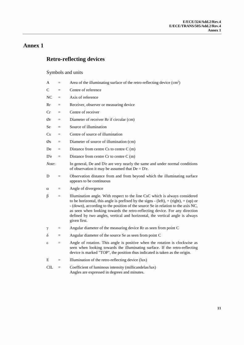
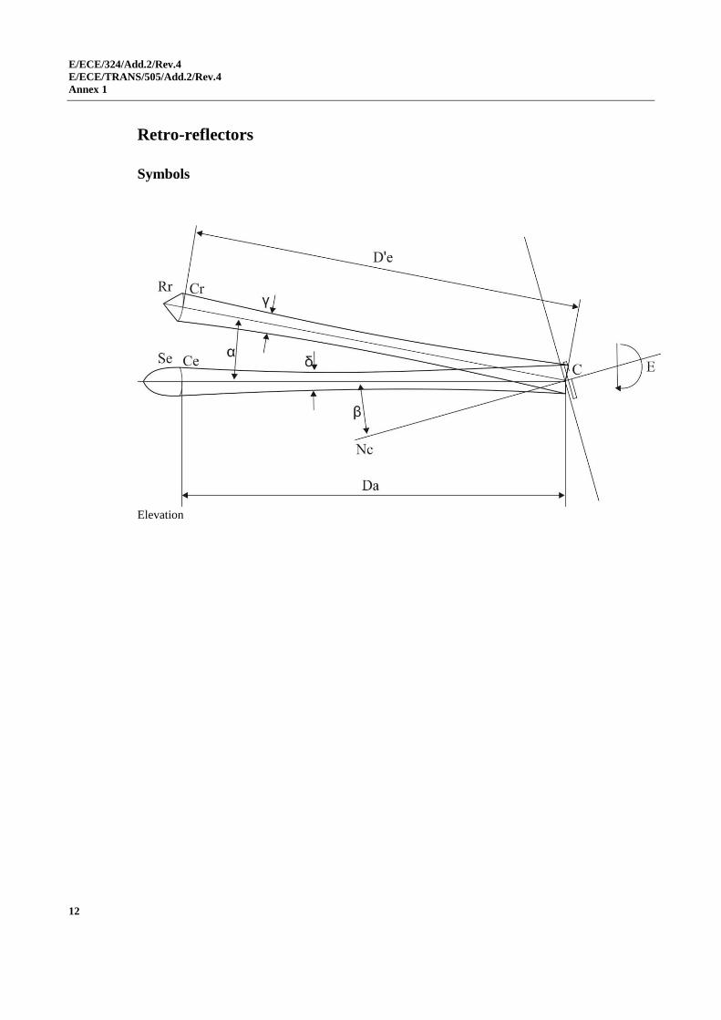
Annex 1
Retro-reflecting devices
Symbols and units
A = Area of the illuminating surface of the retro-reflecting device (cm2)
C = Centre of reference
NC = Axis of reference
Rr = Receiver, observer or measuring device
Cr = Centre of receiver
Ør = Diameter of receiver Rr if circular (cm)
Se = Source of illumination
Cs = Centre of source of illumination
Øs = Diameter of source of illumination (cm)
De = Distance from centre Cs to centre C (m)
D'e = Distance from centre Cr to centre C (m)
Note: In general, De and D'e are very nearly the same and under normal conditions
of observation it may be assumed that De = D'e.
D = Observation distance from and from beyond which the illuminating surface
appears to be continuous
= Angle of divergence
β = Illumination angle. With respect to the line CsC which is always considered
to be horizontal, this angle is prefixed by the signs - (left), + (right), + (up) or
- (down), according to the position of the source Se in relation to the axis NC,
as seen when looking towards the retro-reflecting device. For any direction
defined by two angles, vertical and horizontal, the vertical angle is always
given first.
γ = Angular diameter of the measuring device Rr as seen from point C
δ = Angular diameter of the source Se as seen from point C
ε = Angle of rotation. This angle is positive when the rotation is clockwise as
seen when looking towards the illuminating surface. If the retro-reflecting
device is marked "TOP", the position thus indicated is taken as the origin.
E = Illumination of the retro-reflecting device (lux)
CIL = Coefficient of luminous intensity (millicandelas/lux)
Angles are expressed in degrees and minutes.
E/ECE/324/Add.2/Rev.4
E/ECE/TRANS/505/Add.2/Rev.4
Annex 1
12
Retro-reflectors
Symbols
Elevation
E/ECE/324/Add.2/Rev.4
E/ECE/TRANS/505/Add.2/Rev.4
Annex 2
13
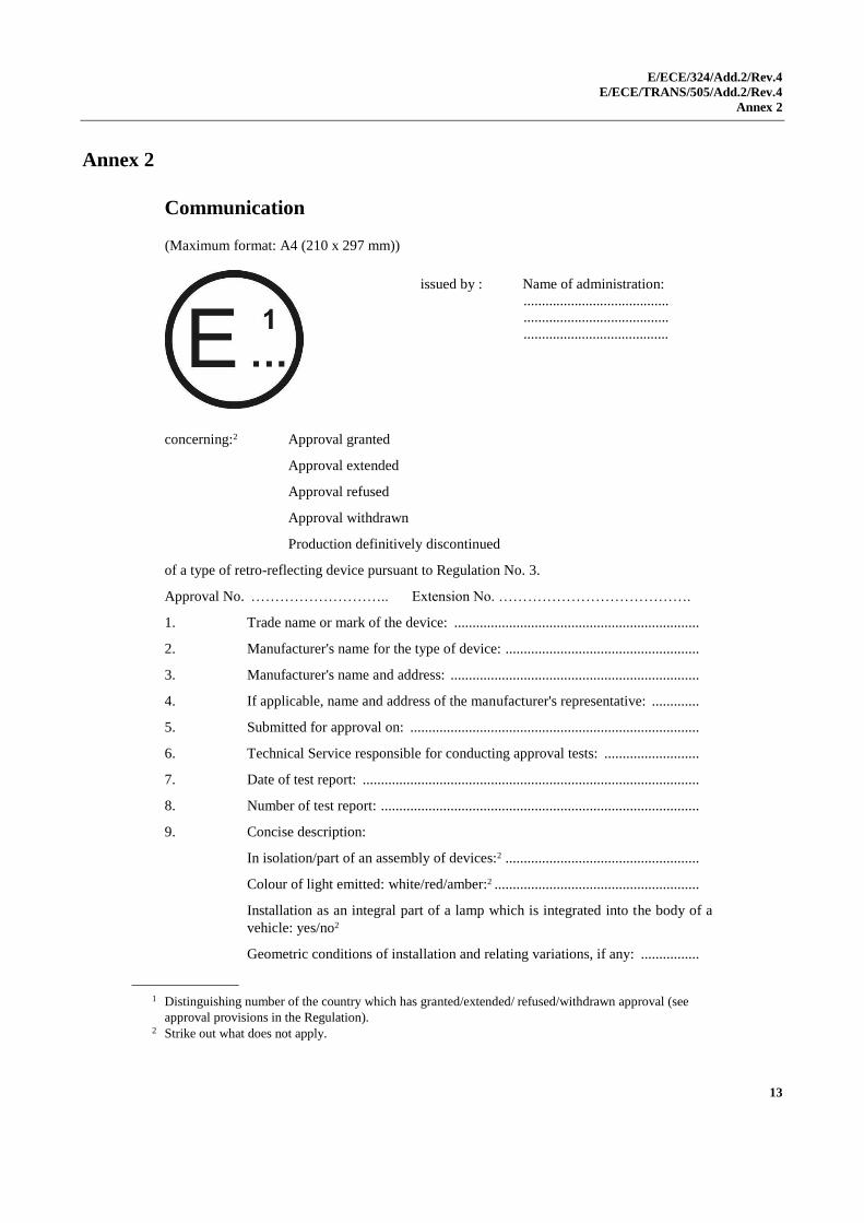
Annex 2
Communication
(Maximum format: A4 (210 x 297 mm))
1
concerning:2 Approval granted
Approval extended
Approval refused
Approval withdrawn
Production definitively discontinued
of a type of retro-reflecting device pursuant to Regulation No. 3.
Approval No. ……………………….. Extension No. ………………………………….
1. Trade name or mark of the device: ...................................................................
2. Manufacturer's name for the type of device: .....................................................
3. Manufacturer's name and address: ....................................................................
4. If applicable, name and address of the manufacturer's representative: .............
5. Submitted for approval on: ...............................................................................
6. Technical Service responsible for conducting approval tests: ..........................
7. Date of test report: ............................................................................................
8. Number of test report: .......................................................................................
9. Concise description:
In isolation/part of an assembly of devices:2 .....................................................
Colour of light emitted: white/red/amber:2 ........................................................
Installation as an integral part of a lamp which is integrated into the body of a
vehicle: yes/no2
Geometric conditions of installation and relating variations, if any: ................
1 Distinguishing number of the country which has granted/extended/ refused/withdrawn approval (see
approval provisions in the Regulation).
2 Strike out what does not apply.
issued by : Name of administration:
........................................
........................................
........................................
E/ECE/324/Add.2/Rev.4
E/ECE/TRANS/505/Add.2/Rev.4
Annex 2
14
10. Position of the approval mark: ..........................................................................
11. Reason(s) for extension (if applicable): ............................................................
12. Approval granted/refused/extended/withdrawn:2
13. Place: ................................................................................................................
14. Date: .................................................................................................................
15. Signature: ..........................................................................................................
16. The following documents, bearing the approval number shown above,
are available on request:
...........................................................................................................................
...........................................................................................................................
...........................................................................................................................
E/ECE/324/Add.2/Rev.4
E/ECE/TRANS/505/Add.2/Rev.4
Annex 3
15
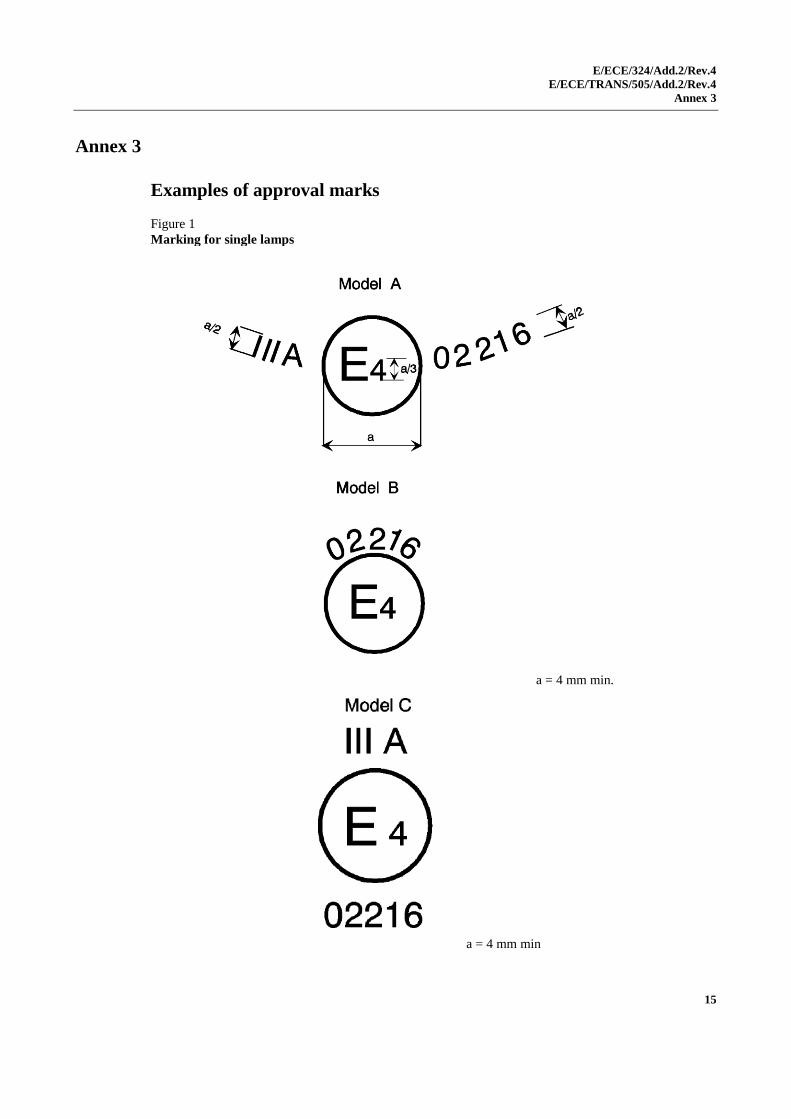
Annex 3
Examples of approval marks
Figure 1
Marking for single lamps
a = 4 mm min.
a = 4 mm min
E/ECE/324/Add.2/Rev.4
E/ECE/TRANS/505/Add.2/Rev.4
Annex 3
16
Note: The above approval number must be placed close to, but in any position in relation
to, the circle surrounding the letter "E". The digits constituting the approval number must
face the same way as the "E". The group of symbols indicating the class must be
diametrically opposite the approval number. The Type Approval Authorities shall avoid
using approval numbers IA, IB, IIIA, IIIB and IVA which might be confused with the class
symbols IA, IB, IIIA, IIIB and IVA.
These sketches show various possible arrangements and are given as examples only.
The above approval mark affixed to a retro-reflecting device shows that the type of
device concerned has been approved in the Netherlands (E 4) under approval number
02216. The approval number shows that approval was granted in accordance with the
requirements of the Regulation as modified by the 02 series of amendments.
E/ECE/324/Add.2/Rev.4
E/ECE/TRANS/505/Add.2/Rev.4
Annex 3
17
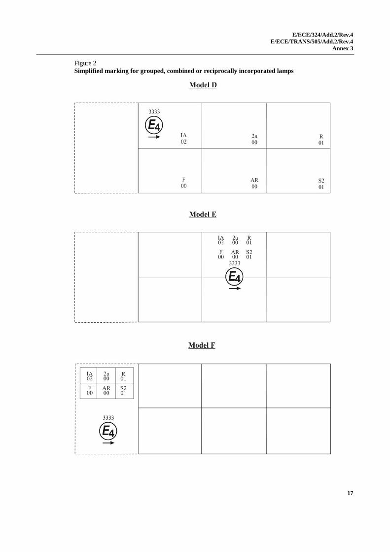
Figure 2
Simplified marking for grouped, combined or reciprocally incorporated lamps
E/ECE/324/Add.2/Rev.4
E/ECE/TRANS/505/Add.2/Rev.4
Annex 3
18
Note: The three examples of approval marks, models D, E and F, represent three possible
variants of the marking of a lighting device when two or more lamps are part of the same
unit of grouped, combined or reciprocally incorporated lamps. This approval mark shows
that the device was approved in the Netherlands (E 4) under approval number 3333 and
comprising:
A retro-reflector of Class IA approved in accordance with the 02 series of
amendments to Regulation No. 3;
A rear direction indicator of category 2a approved in accordance with Regulation
No. 6 in its original form;
A red rear position lamp (R) approved in accordance with the 01 series of
amendments to Regulation No. 7;
A rear fog lamp (F) approved in accordance with Regulation No. 38 in its original
form;
A reversing lamp (AR) approved in accordance with Regulation No. 23 in its
original form;
A stop lamp with two levels of illumination (S2) approved in accordance with the 01
series of amendments to Regulation No. 7.
E/ECE/324/Add.2/Rev.4
E/ECE/TRANS/505/Add.2/Rev.4
Annex 4
19
Annex 4
Test procedure - Class IA and Class IIIA
1. The applicant shall submit for approval ten samples which shall be tested in
the chronological order indicated in Annex 12.
2. After verification of the general specifications (paragraph 6. of the
Regulation) and the specifications of shape and dimensions (Annex 5), the
ten samples shall be subjected to the heat resistance test described in
Annex 10 and at least one hour after this test examined as to their
colorimetric characteristics and CIL (Annex 7) for an angle of divergence of
20' and an illumination angle V = H = 0° or if necessary, in the position
defined in Annex 7, paragraphs 4. and 4.1. The two retro-reflecting devices
giving the minimum and maximum values shall then be fully tested as shown
in Annex 7. These two samples shall be kept by the laboratories for any
further checks which may be found necessary. The other eight samples shall
be divided into four groups of two:
First group: The two samples shall be subjected successively to the
water penetration test (Annex 8, paragraph 1.1.) and
then, if this test is satisfactory, to the tests for resistance
to fuels and lubricants (Annex 8, paragraphs 3. and 4.).
Second group: The two samples shall, if necessary, be subjected to the
corrosion test (Annex 8, paragraph 2.), and then to the
abrasive-strength test of the rear face of the retro-
reflecting device (Annex 8, paragraph 5.).
Third group: The two samples shall be subjected to the test for
stability in time of the optical properties of retro-
reflecting device (Annex 9).
Fourth group: The two samples shall be subjected to the colour-
fastness test (Annex 11).
3. After undergoing the tests referred to in the above paragraph, the retro-
reflecting devices in each group must have:
3.1. A colour which satisfies the conditions laid down in Annex 6. This shall be
verified by a qualitative method and, in case of doubt, confirmed by a
quantitative method.
3.2. A CIL which satisfies the conditions laid down in Annex 7. The verification
shall be performed only for an angle of divergence of 20' and an illumination
angle of V = H = 0° or, if necessary, in the position specified in Annex 7,
paragraphs 4. and 4.1.
E/ECE/324/Add.2/Rev.4
E/ECE/TRANS/505/Add.2/Rev.4
Annex 5
20
Annex 5
Specifications of shape and dimensions
1. Shape and dimensions of retro-reflecting devices in Class IA or IB
1.1. The shape of the illuminating surfaces must be simple, and not easily
confused at normal observation distances, with a letter, a digit or a triangle.
1.2. The preceding paragraph notwithstanding, a shape resembling the letters or
digits of simple form O, I, U or 8 is permissible.
2. Shape and dimensions of retro-reflecting devices in Classes IIIA and IIIB
(see appendix to this annex)
2.1. The illuminating surfaces of retro-reflecting devices in Classes IIIA and IIIB
must have the shape or an equilateral triangle. If the word "TOP" is inscribed
in one corner, the apex of that corner must be directed upwards.
2.2. The illuminating surface may or may not have at its centre a triangular, non-
retro-reflecting area, with sides parallel to those of the outer triangle.
2.3. The illuminating surface may or may not be continuous. In any case, the
shortest distance between two adjacent retro-reflecting optical units must not
exceed 15 mm.
2.4. The illuminating surface of a retro-reflecting device shall be considered to be
continuous if the edges of the illuminating surfaces of adjacent separate
optical units are parallel and if the said optical units are evenly distributed
over the whole solid surface of the triangle.
2.5. If the illuminated surface is not continuous, the number of separate retro-
reflecting optical units including the corner units shall not be less than four
on each side of the triangle.
2.5.1. The separate retro-reflecting optical units shall not be replaceable unless they
consist of approved retro-reflecting devices in Class IA.
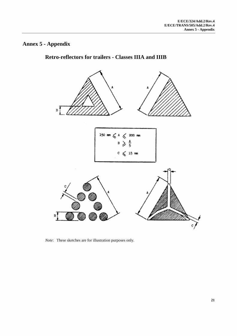
2.6. The outside edges of the illuminating surfaces of triangular retro-reflecting
devices in Classes IIIA and IIIB shall be between 150 and 200 mm long. In
the case of devices of hollow-triangle type, the width of the sides, measured
at right angles to the latter, shall be equal to at least 20 per cent of the
effective length between the extremities of the illuminating surface.
3. Shape and dimensions of retro-reflecting devices in Class IVA
3.1. The shape of the light emitting surfaces must be simple and not easily
confused at normal observation distances with a letter, a digit or a triangle.
However, a shape resembling the letters and digits of simple form, O, I, U
and 8 is permissible.
3.2. The light emitting surface of the retro-reflecting device must be at least
25 cm2.
4. Compliance with the above specifications shall be verified by visual
inspection.
E/ECE/324/Add.2/Rev.4
E/ECE/TRANS/505/Add.2/Rev.4
Annex 5 - Appendix
21
Annex 5 - Appendix
Retro-reflectors for trailers - Classes IIIA and IIIB
Note: These sketches are for illustration purposes only.
E/ECE/324/Add.2/Rev.4
E/ECE/TRANS/505/Add.2/Rev.4
Annex 6
22
Annex 6
Colorimetric specifications
1. These specifications shall apply only to clear, red or amber retro-reflecting
devices.
1.1. Retro-reflecting devices may consist of a combined retro-reflecting optical
unit and filter, which must be so designed that they cannot be separated under
normal conditions of use.
1.2. The colouring of retro-reflecting optical units and filters by means of paint or
varnish is not permitted.
2. When the retro-reflecting device is illuminated by CIE standard illuminant A,
with an angle of divergence of 1/3 degrees and an illumination angle of
V = H = 0 degree, or, if this produces a colourless surface reflection, an
angle V = +/- 5 degrees, H = 0 degree, the trichromatic coordinates of the
reflected luminous flux must be within the limits according to
paragraph 2.30. of Regulation No. 48.
3. Clear retro-reflecting devices must not produce a selective reflection, that is
to say, the trichromatic coordinates "x" and "y" of the standard illuminant
"A" used to illuminate the retro-reflecting device must not undergo a change
of more than 0.01 after reflection by the retro-reflecting device.
E/ECE/324/Add.2/Rev.4
E/ECE/TRANS/505/Add.2/Rev.4
Annex 7
23
Annex 7
Photometric specifications
1. When applying for approval, the applicant shall specify one or more or a
range of axis of reference, corresponding to the illumination angle
V = H = 0° in the table of coefficients of luminous intensity (CIL).
In the case where more than one or a range of different axis of reference are
specified by the manufacturer, the photometric measurements shall be
repeated making reference each time to a different axis of reference or to the
extreme axis of reference of the range specified by the manufacturer.
2. For photometric measurements, only the illuminating surface defined by the
planes contiguous to the outermost parts of the optical system of the retro-
reflecting device as indicated by the manufacturer and contained within a
circle of 200 mm diameter for Class IA or IB shall be considered, and the
illuminating surface itself shall be limited to 100 cm2 though the surfaces of
the retro-reflecting optical units need not necessarily attain this area. The
manufacturer shall specify the perimeter of the area to be used. In the case of
Class IIIA, Class IIIB and Class IVA, the whole of the illuminating surfaces
shall be considered without limitation as to size.
3. CIL values
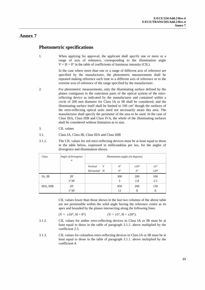
3.1. Class IA, Class IB, Class IIIA and Class IIIB
3.1.1. The CIL values for red retro-reflecting devices must be at least equal to those
in the table below, expressed in millicandelas per lux, for the angles of
divergence and illumination shown.
Class Angle of divergence
α
Illumination angles (in degrees)
Vertical V
Horizontal H
0°
0°
±10°
0°
±5°
±20°
IA, IB 20'
1°30'
300
5
200
2.8
100
2.5
IIIA, IIIB 20'
1°30'
450
12
200
8
150
8
CIL values lower than those shown in the last two columns of the above table
are not permissible within the solid angle having the reference centre as its
apex and bounded by the planes intersecting along the following lines:
(V = ±10°, H = 0°) (V = ±5°, H = ±20°).
3.1.2. CIL values for amber retro-reflecting devices in Class IA or IB must be at
least equal to those in the table of paragraph 3.1.1. above multiplied by the
coefficient 2.5.
3.1.3. CIL values for colourless retro-reflecting devices in Class IA or IB must be at
least equal to those in the table of paragraph 3.1.1. above multiplied by the
coefficient 4.
E/ECE/324/Add.2/Rev.4
E/ECE/TRANS/505/Add.2/Rev.4
Annex 7
24
3.2. However, in the case where a retro-reflecting device of Class IA, Class IB,
Class IIIA or Class IIIB is intended to be installed with its H plane at a
mounting height less than 750 mm above the ground, the CIL values are
verified only up to an angle of 5° downwards.
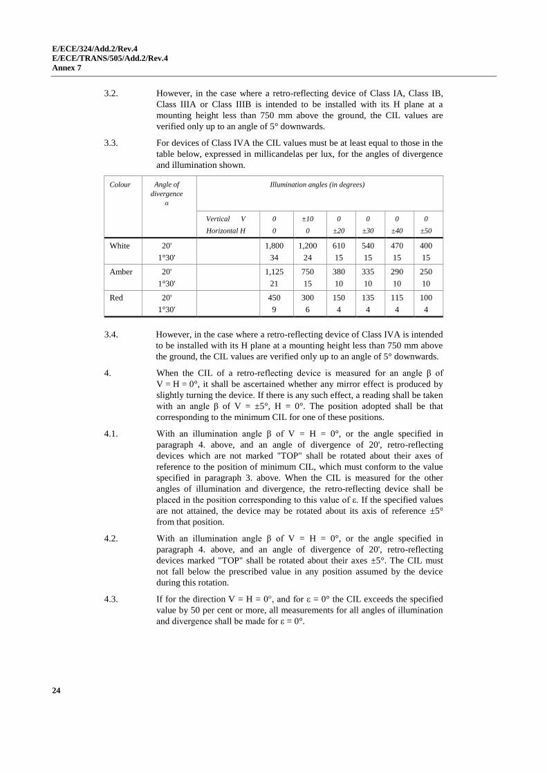
3.3. For devices of Class IVA the CIL values must be at least equal to those in the
table below, expressed in millicandelas per lux, for the angles of divergence
and illumination shown.
Colour Angle of
divergence
α
Illumination angles (in degrees)
Vertical V
Horizontal H
0
0
±10
0
0
±20
0
±30
0
±40
0
±50
White 20'
1°30'
1,800
34
1,200
24
610
15
540
15
470
15
400
15
Amber 20'
1°30'
1,125
21
750
15
380
10
335
10
290
10
250
10
Red 20'
1°30'
450
9
300
6
150
4
135
4
115
4
100
4
3.4. However, in the case where a retro-reflecting device of Class IVA is intended
to be installed with its H plane at a mounting height less than 750 mm above
the ground, the CIL values are verified only up to an angle of 5° downwards.
4. When the CIL of a retro-reflecting device is measured for an angle β of
V = H = 0°, it shall be ascertained whether any mirror effect is produced by
slightly turning the device. If there is any such effect, a reading shall be taken
with an angle β of V = ±5°, H = 0°. The position adopted shall be that
corresponding to the minimum CIL for one of these positions.
4.1. With an illumination angle β of V = H = 0°, or the angle specified in
paragraph 4. above, and an angle of divergence of 20', retro-reflecting
devices which are not marked "TOP" shall be rotated about their axes of
reference to the position of minimum CIL, which must conform to the value
specified in paragraph 3. above. When the CIL is measured for the other
angles of illumination and divergence, the retro-reflecting device shall be
placed in the position corresponding to this value of ε. If the specified values
are not attained, the device may be rotated about its axis of reference ±5°
from that position.
4.2. With an illumination angle β of V = H = 0°, or the angle specified in
paragraph 4. above, and an angle of divergence of 20', retro-reflecting
devices marked "TOP" shall be rotated about their axes ±5°. The CIL must
not fall below the prescribed value in any position assumed by the device
during this rotation.
4.3. If for the direction V = H = 0°, and for ε = 0° the CIL exceeds the specified
value by 50 per cent or more, all measurements for all angles of illumination
and divergence shall be made for ε = 0°.
E/ECE/324/Add.2/Rev.4
E/ECE/TRANS/505/Add.2/Rev.4
Annex 8
25
Annex 8
Resistance to external agents
1. Resistance to water and dirt penetration
1.1. Water submersion test
1.1.1. Retro-reflecting devices whether part of a lamp or not, shall be stripped of all
removable parts and immersed for 10 minutes in water at a temperature of
50 ± 5 °C, the highest point of the upper part of the illuminating surface
being 20 mm below the surface of the water. This test shall be repeated after
turning the retro-reflecting device through 180°, so that the illuminating
surface is at the bottom and the rear face is covered by about 20 mm of water.
These optical units shall then be immediately immersed in the same
conditions in water at a temperature of 25 ± 5 °C.
1.1.2. No water shall penetrate to the reflecting surface of the retro-reflecting
optical unit. If visual inspection clearly reveals the presence of water, the
device shall not be considered to have passed the test.
1.1.3. If visual inspection does not reveal the presence of water or in case of doubt,
the CIL shall be measured by the method described in Annex 4,
paragraph 3.2., or Annex 14, paragraph 4.2., the retro-reflecting device being
first lightly shaken to remove excess water from the outside.
1.2. Alternative test procedure for Classes IB and IIIB devices
As an alternative, at the request of the manufacturer, the following test
(moisture and dust test) shall be applied instead of the submersion-test
specified in paragraph 1.1. above.
1.2.1. Moisture test
The test evaluates the ability of the sample device to resist moisture
penetration from a water spray and determines the drainage capability of
those devices with drain holes or other exposed openings in the device.
1.2.1.1. Water spray test equipment
A water spray cabinet with the following characteristics shall be used:
1.2.1.1.1. Cabinet
The cabinet shall be equipped with a nozzle(s) which provides a solid cone
water spray of sufficient angle to completely cover the sample device. The
centreline of the nozzle(s) shall be directed downward at an angle of 45°± 5°
to the vertical axis of a rotating test platform.
1.2.1.1.2. Rotating test platform
The rotating test platform shall have a minimum diameter of 140 mm and
rotate about a vertical axis in the centre of the cabinet.
E/ECE/324/Add.2/Rev.4
E/ECE/TRANS/505/Add.2/Rev.4
Annex 8
26
1.2.1.1.3. Precipitation rate
The precipitation rate of the water spray at the device shall be 2.5 (+1.6/-0)
mm/min as measured with a vertical cylindrical collector centred on the
vertical axis of the rotating test platform. The height of the collector shall be
100 mm and the inside diameter shall be a minimum of 140 mm.
1.2.1.2. Water spray test procedure
A sample device mounted on a test fixture, with initial CIL measured and
recorded shall be subjected to a water spray as follows:
1.2.1.2.1. Device openings
All drain holes and other openings shall remain open. Drain wicks, when
used, shall be tested in the device.
1.2.1.2.2. Rotational speed
The device shall be rotated about its vertical axis at a rate of 4.0 ± 0.5 min -1.
1.2.1.2.3. If the retro-reflector is reciprocally incorporated or grouped with signalling or
lighting functions, these functions shall be operated at design voltage
according to a cycle of 5 min ON (in flashing mode, where appropriate),
55 min OFF.
1.2.1.2.4. Test duration
The water spray test shall last 12 hours (12 cycles of 5/55 min).
1.2.1.2.5. Drain period
The rotation and the water spray shall be turned OFF and the device allowed
to drain for 1 hour with the cabinet door closed.
1.2.1.2.6. Sample evaluation
Upon completion of the drain period. The interior of the device shall be
observed for moisture accumulation. No standing pool of water shall be
allowed to be formed, or which can be formed by tapping or tilting the
device. The CIL shall be measured according to the method specified in
Annex 4 paragraph 3.2. after having dried the exterior of the device with a
dry cotton cloth.
1.2.2. Dust exposure test
This test evaluates the ability of the sample device to resist dust penetration
which could significantly affect the photometric output of the retro-reflector.
1.2.2.1. Dust exposure test equipment
The following equipment shall be used to test for dust exposure:
1.2.2.1.1. Dust exposure test chamber
The interior of the test chamber shall be cubical in shape in size 0.9 to 1.5 m
per side. The bottom may be "hopper shaped" to aid in collecting the dust.
The internal chamber volume, not including a "hopper shaped" bottom shall
be 2 m3 maximum and shall be charged with 3 to 5 kg of the test dust. The
chamber shall have the capability of agitating the test dust by means of
compressed air or blower fans in such a way that the dust is diffused
throughout the chamber.
E/ECE/324/Add.2/Rev.4
E/ECE/TRANS/505/Add.2/Rev.4
Annex 8
27
1.2.2.1.2. The dust
The test dust used shall be fine powdered cement in accordance with standard
ASTM C 150-84.*
1.2.2.2. Dust exposure test procedure
A sample device, mounted on a test fixture, with the initial CIL measured and
recorded, shall be exposed to dust as follows:
1.2.2.2.1. Device openings
All drain holes and other openings shall remain open. Drain wicks, when
used, shall be tested in the device.
1.2.2.2.2. Dust exposure
The mounted device shall be placed in the dust chamber no closer than
150 mm from a wall. Devices with a length exceeding 600 mm shall be
horizontally centred in the test chamber. The test dust shall be agitated as
completely as possible by compressed air or blower(s) at intervals of 15 min
for a period of 2 to 15 s for the duration of 5 hours. The dust shall be allowed
to settle between the agitation periods.
1.2.2.2.3. Measured sample evaluation
Upon completion of the dust exposure test, the exterior of the device shall be
cleaned and dried with a dry cotton cloth and the CIL measured according to
the method specified in Annex 4, paragraph 3.2.
2. Resistance to corrosion
2.1. Retro-reflecting devices must be so designed that they retain the prescribed
photometric and colorimetric characteristics despite the humidity and
corrosive influences to which they are normally exposed. The resistance of
the front surface to tarnishing and of the protection of the rear face to
deterioration shall be checked, particularly when an essential metal
component seems liable to be attacked.
2.2. The retro-reflecting device, or the lamp if the device is combined with a light,
shall be stripped of all removable parts and subjected to the action of a saline
mist for a period of 50 hours, comprising two periods of exposure of 24 hours
each, separated by an interval of two hours during which the sample is
allowed to dry.
2.3. The saline mist shall be produced by atomizing, at a temperature of
35 °C ± 2 °C, a saline solution obtained by dissolving 20 ± 2 parts by weight
of sodium chloride in 80 parts of distilled water containing not more than
0.02 per cent of impurities.
2.4. Immediately after completion of the test, the sample must not show signs of
excessive corrosion liable to impair the efficiency of the device.
* American Society for Testing and Materials
E/ECE/324/Add.2/Rev.4
E/ECE/TRANS/505/Add.2/Rev.4
Annex 8
28
3. Resistance to fuels
The outer surface of the retro-reflecting device and, in particular, of the
illuminating surface, shall be lightly wiped with a cotton cloth soaked in a
mixture of 70 vol. per cent of n-heptane and 30 vol. per cent of toluol. After
about five minutes, the surface shall be inspected visually. It must not show
any apparent surface changes, except that slight surface cracks will not be
objected to.
4. Resistance to lubricating oils
The outer surface of the retro-reflecting device and, in particular, the
illuminating surface, shall be lightly wiped with a cotton cloth soaked in a
detergent lubricating oil. After about 5 minutes, the surface shall be cleaned.
The CIL shall then be measured (Annex 4, paragraph 3.2. or Annex 14,
paragraph 4.2.).
5. Resistance of the accessible rear face of mirror-backed retro-reflecting
devices
5.1. After having brushed the rear face of the retro-reflecting device with a hard
nylon brush, a cotton cloth soaked in the mixture, defined in paragraph 3.
Above shall be applied to the said rear face for one minute. The cotton cloth
is then removed and the retro-reflecting device left to dry.
5.2. As soon as evaporation is completed, an abrasion test shall be made by
brushing the rear face with the same nylon brush as before.
5.3. The CIL shall then be measured (Annex 4, paragraph 3.2. or Annex 14,
paragraph 4.2.) after the whole surface of the mirror-backed rear face has
been covered with Indian ink.
E/ECE/324/Add.2/Rev.4
E/ECE/TRANS/505/Add.2/Rev.4
Annex 9
29
Annex 9
Stability in time of the optical properties1 of retro-reflecting devices
1. The Type Approval Authority which granted approval shall have the right to
check the stability in time of the optical properties of a type of retro-
reflecting device in service.
2. The competent authorities of countries other than the country in which
approval was granted may carry out similar checks in their territory. If a type
of retro-reflector in use exhibits a systematic defect, the said authorities shall
transmit any components removed for examination to the Type Approval
Authority which granted approval, with a request for its opinion.
3. In the absence of other criteria, the concept of "systematic defect" of a type of
retro-reflector in use shall be interpreted in conformity with the intention of
paragraph 6.1. of this Regulation.
1 Despite the importance of tests to check the stability in time of the optical properties of retro-
reflecting devices, it is in the present state of the art not yet possible to assess this stability by
laboratory tests of limited duration.
E/ECE/324/Add.2/Rev.4
E/ECE/TRANS/505/Add.2/Rev.4
Annex 10
30
Annex 10
Resistance to heat
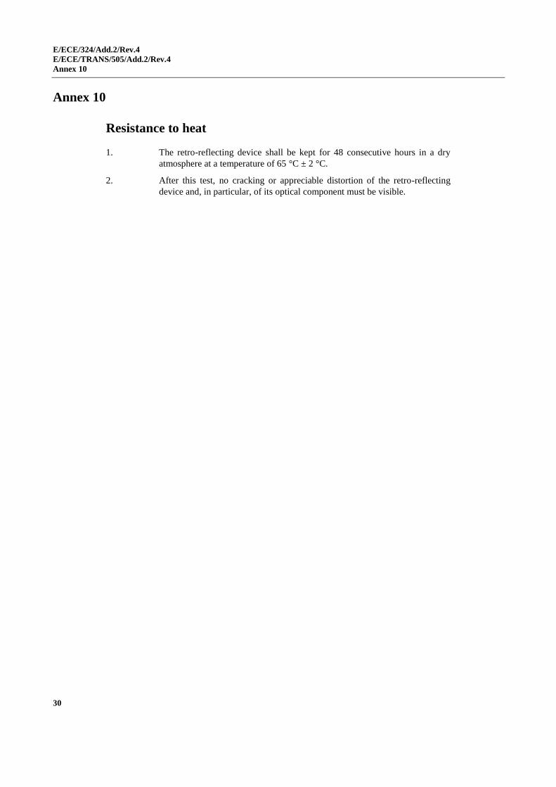
1. The retro-reflecting device shall be kept for 48 consecutive hours in a dry
atmosphere at a temperature of 65 °C ± 2 °C.
2. After this test, no cracking or appreciable distortion of the retro-reflecting
device and, in particular, of its optical component must be visible.
E/ECE/324/Add.2/Rev.4
E/ECE/TRANS/505/Add.2/Rev.4
Annex 11
31
Annex 11
Colour-fastness1
1. The Type Approval Authority which granted approval shall have the right to
check the colour-fastness of a type of retro-reflecting device in service.
2. The competent authorities of countries other than the country in which
approval was granted may carry out similar checks in their territory. If a type
of retro-reflector in use exhibits a systematic defect, the said authorities shall
transmit any components removed for examination to the Type Approval
Authority which granted approval, with a request for its opinion.
3. In the absence of other criteria, the concept "systematic defect" of a type of
retro-reflector in use shall be interpreted in conformity with the intention of
paragraph 9.1. of this Regulation.
1 Despite the importance of tests to check the colour-fastness of retro-reflecting devices, it is in the
present state of the art not yet possible to assess colour-fastness by laboratory tests of limited
duration.
E/ECE/324/Add.2/Rev.4
E/ECE/TRANS/505/Add.2/Rev.4
Annex 12
32
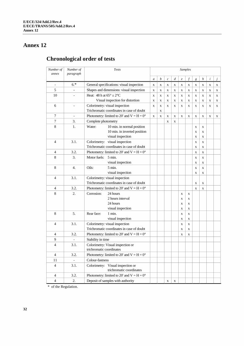
Annex 12
Chronological order of tests
Number of
annex
Number of
paragraph
Tests Samples
a b c d e f g h i j
- 6.* General specifications: visual inspection x x x x x x x x x x
5 - Shapes and dimensions: visual inspection x x x x x x x x x x
10 - Heat: 48 h at 65° ± 2°C
Visual inspection for distortion
x
x
x
x
x
x
x
x
x
x
x
x
x
x
x
x
x
x
x
x
6 - Colorimetry: visual inspection
Trichromatic coordinates in case of doubt
x
x
x
x x x x x x x x
7 - Photometry: limited to 20' and V = H = 0° x x x x x x x x x x
7 3. Complete photometry x x
8 1. Water: 10 min. in normal position
10 min. in inverted position
visual inspection
x
x
x
x
x
x
4 3.1. Colorimetry: visual inspection
Trichromatic coordinates in case of doubt
x
x
x
x
4 3.2. Photometry: limited to 20' and V = H = 0° x x
8 3. Motor fuels: 5 min.
visual inspection
x
x
x
x
8 4. Oils: 5 min.
visual inspection
x
x
x
x
4 3.1. Colorimetry: visual inspection
Trichromatic coordinates in case of doubt
x
x
4 3.2. Photometry: limited to 20' and V = H = 0° x x
8 2. Corrosion: 24 hours
2 hours interval
24 hours
visual inspection
x
x
x
x
x
x
x
x
8 5. Rear face: 1 min.
visual inspection
x
x
x
x
4 3.1. Colorimetry: visual inspection
Trichromatic coordinates in case of doubt
x
x
x
x
4 3.2. Photometry: limited to 20' and V = H = 0° x x
9 - Stability in time
4 3.1. Colorimetry: Visual inspection or
trichromatic coordinates
4 3.2. Photometry: limited to 20' and V = H = 0°
11 - Colour-fastness
4 3.1. Colorimetry: Visual inspection or
trichromatic coordinates
4 3.2. Photometry: limited to 20' and V = H = 0°
4 2. Deposit of samples with authority x x
* of the Regulation.
E/ECE/324/Add.2/Rev.4
E/ECE/TRANS/505/Add.2/Rev.4
Annex 13
33
Annex 13
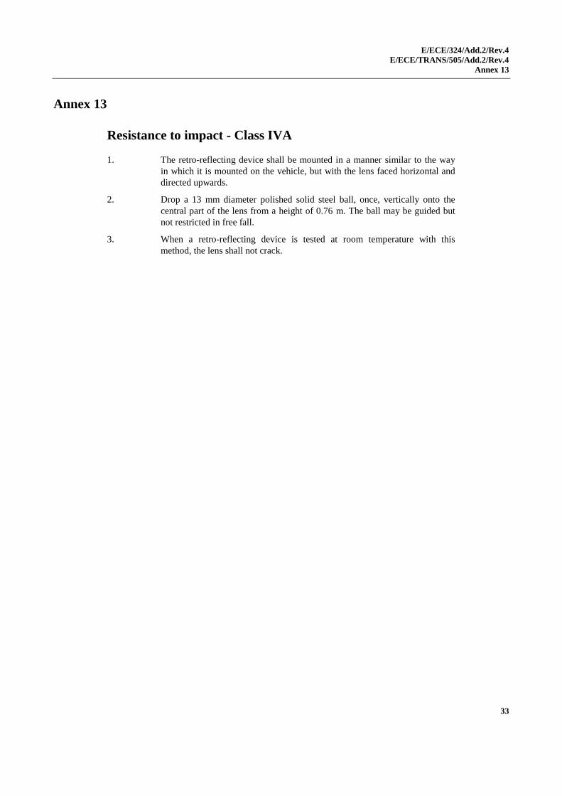
Resistance to impact - Class IVA
1. The retro-reflecting device shall be mounted in a manner similar to the way
in which it is mounted on the vehicle, but with the lens faced horizontal and
directed upwards.
2. Drop a 13 mm diameter polished solid steel ball, once, vertically onto the
central part of the lens from a height of 0.76 m. The ball may be guided but
not restricted in free fall.
3. When a retro-reflecting device is tested at room temperature with this
method, the lens shall not crack.
E/ECE/324/Add.2/Rev.4
E/ECE/TRANS/505/Add.2/Rev.4
Annex 14
34
Annex 14
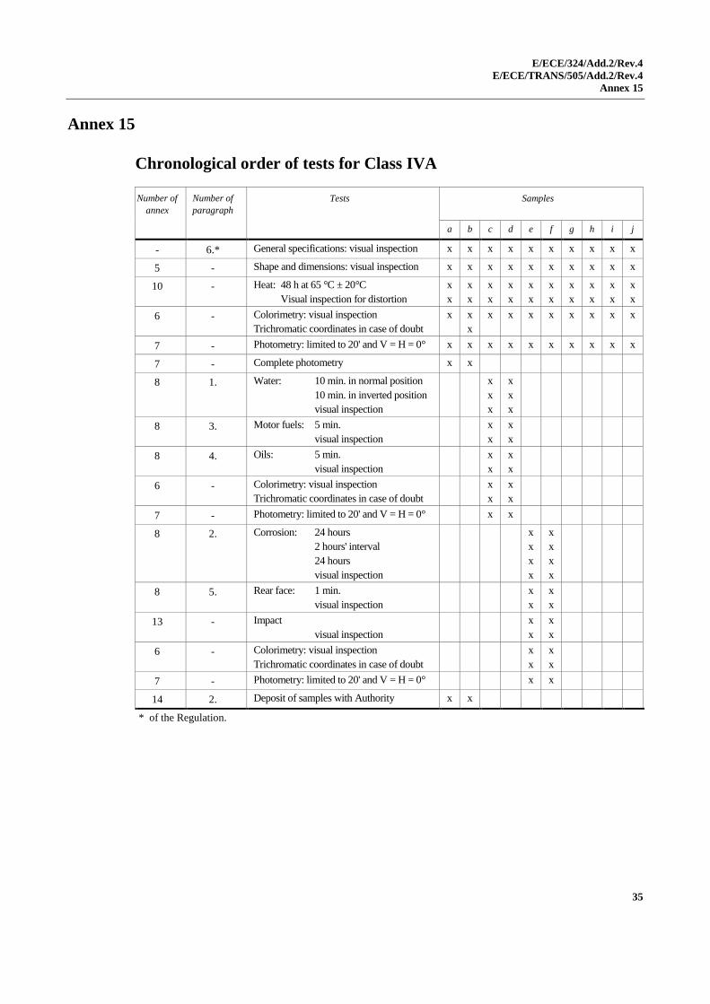
Test procedure - Class IVA
1. The applicant shall submit for approval ten samples which shall be tested in
the chronological order indicated in Annex 15.
2. After verification of the specifications in paragraphs 6.1. to 6.5. of this
Regulation and the specifications of shape and dimensions (Annex 5), the ten
samples shall be subjected to the heat resistance test (Annex 10) and one hour
minimum after this test examined as to their colorimetric characteristics and
CIL (Annex 7) for an angle of divergence of 20' and an illumination angle
V = H = 0° or, if necessary, in the positions defined in Annex 7. The two
retro-reflecting devices giving the minimum and maximum values shall then
be fully tested as shown in Annex 7. These two samples shall be kept by the
laboratories for any further checks which may be found necessary.
3. Four samples out of the remaining eight samples shall be selected at random
and divided into two groups of two in each group.
First group:
The two samples shall be subjected successively to the water-penetration
resistance test (Annex 8, paragraph 1.) and then, if this test is satisfactory, to
the tests for resistance to fuels and lubricating oils (Annex 8, paragraphs 3.
and 4.).
Second group:
The two samples shall, if relevant, be subjected to the corrosion test
(Annex 8, paragraph 2.), and then to the abrasive-strength test of the rear face
of the retro-reflecting device (Annex 8, paragraph 5.). These two samples
shall also be subjected to the impact test (Annex 13).
4. After undergoing the tests referred to in the above paragraph, the retro-
reflecting devices in each group must have:
4.1. A colour which satisfies the conditions laid down in Annex 6. This shall be
verified by a qualitative method and, in case of doubt, confirmed by a
quantitative method;
4.2. A CIL which satisfies the conditions laid down in Annex 7. Verification shall
be performed only for an angle of divergence of 20' and an illumination angle
of V = H = 0° or, if necessary, in the positions specified in Annex 7.
5. The four remaining samples can be utilized, if necessary, for any other
purpose.
E/ECE/324/Add.2/Rev.4
E/ECE/TRANS/505/Add.2/Rev.4
Annex 15
35
Annex 15
Chronological order of tests for Class IVA
Number of
annex
Number of
paragraph
Tests Samples
a b c d e f g h i j
- 6.* General specifications: visual inspection x x x x x x x x x x
5 - Shape and dimensions: visual inspection x x x x x x x x x x
10 - Heat: 48 h at 65 °C ± 20°C
Visual inspection for distortion
x
x
x
x
x
x
x
x
x
x
x
x
x
x
x
x
x
x
x
x
6 - Colorimetry: visual inspection
Trichromatic coordinates in case of doubt
x
x
x
x x x x x x x x
7 - Photometry: limited to 20' and V = H = 0° x x x x x x x x x x
7 - Complete photometry x x
8 1. Water: 10 min. in normal position
10 min. in inverted position
visual inspection
x
x
x
x
x
x
8 3. Motor fuels: 5 min.
visual inspection
x
x
x
x
8 4. Oils: 5 min.
visual inspection
x
x
x
x
6 - Colorimetry: visual inspection
Trichromatic coordinates in case of doubt
x
x
x
x
7 - Photometry: limited to 20' and V = H = 0° x x
8 2. Corrosion: 24 hours
2 hours' interval
24 hours
visual inspection
x
x
x
x
x
x
x
x
8 5. Rear face: 1 min.
visual inspection
x
x
x
x
13 - Impact
visual inspection
x
x
x
x
6 - Colorimetry: visual inspection
Trichromatic coordinates in case of doubt
x
x
x
x
7 - Photometry: limited to 20' and V = H = 0° x x
14 2. Deposit of samples with Authority x x
* of the Regulation.
E/ECE/324/Add.2/Rev.4
E/ECE/TRANS/505/Add.2/Rev.4
Annex 16
36
Annex 16
Test procedure for Classes IB and IIIB devices
Retro-reflecting devices of Classes IB and IIIB shall be tested according to the test
procedures specified in Annex 4, following the chronological order of tests given in
Annex 12, with the exception of the test according to Annex 8, paragraph 1., which for
Classes IB and IIIB devices may be replaced by the test specified in Annex 8,
paragraph 1.2.
E/ECE/324/Add.2/Rev.4
E/ECE/TRANS/505/Add.2/Rev.4
Annex 17
37
Annex 17
Minimum requirements for conformity of production control procedures
1. General
1.1. The conformity requirements shall be considered satisfied from a mechanical
and geometric standpoint, if the differences do not exceed inevitable
manufacturing deviations within the requirements of this Regulation.
1.2. With respect to photometric performances, the conformity of mass-produced
retro-reflectors shall not be contested if, when testing photometric
performances of any retro-reflector chosen at random no measured value
deviates unfavourably by more than 20 per cent from the minimum values
prescribed in this Regulation.
1.3. The chromaticity coordinates shall be complied with.
2. Minimum requirements for verification of conformity by the manufacturer
For each type of retro-reflector the holder of the approval mark shall carry
out at least the following tests, at appropriate intervals. The tests shall be
carried out in accordance with the provisions of this Regulation.
If any sampling shows non-conformity with regard to the type of test
concerned, further samples shall be taken and tested. The manufacturer shall
take steps to ensure the conformity of the production concerned.
2.1. Nature of tests
Tests of conformity in this Regulation shall cover the photometric and
colorimetric characteristics and the resistance to penetration of water.
2.2. Methods used in tests
2.2.1. Tests shall generally be carried out in accordance with the methods set out in
this Regulation.
2.2.2. In any test of conformity carried out by the manufacturer, equivalent methods
may be used with the consent of the Type Approval Authority. The
manufacturer is responsible for proving that the applied methods are
equivalent to those laid down in this Regulation.
2.2.3. The application of paragraphs 2.2.1. and 2.2.2. above requires regular
calibration of test apparatus and its correlation with measurements made by a
competent authority.
2.2.4. In all cases the reference methods shall be those of this Regulation,
particularly for the purpose of administrative verification and sampling.
2.3. Nature of sampling
Samples of retro-reflectors shall be selected at random from the production of
a uniform batch. A uniform batch means a set of retro-reflectors of the same
type, defined according to the production methods of the manufacturer.
E/ECE/324/Add.2/Rev.4
E/ECE/TRANS/505/Add.2/Rev.4
Annex 17
38
The assessment shall in general cover series production from individual
factories. However, a manufacturer may group together records concerning
the same type from several factories, provided these operate under the same
quality system and quality management.
2.4. Measured and recorded photometric characteristics
The sampled retro-reflector shall be subjected to photometric measurements
at the points and the chromaticity coordinates provided for in the Regulation.
2.5. Criteria governing acceptability
The manufacturer is responsible for carrying out a statistical study of the test
results and for defining, in agreement with the Type Approval Authority,
criteria governing the acceptability of his products in order to meet the
specifications laid down for the verification of conformity of products in
paragraph 8.1. of this Regulation.
The criteria governing the acceptability shall be such that, with a confidence
level of 95 per cent, the minimum probability of passing a spot check in
accordance with Annex 18 (first sampling) would be 0.95.
E/ECE/324/Add.2/Rev.4
E/ECE/TRANS/505/Add.2/Rev.4
Annex 18
39
Annex 18
Minimum requirements for sampling by an inspector
1. General
1.1. The conformity requirements shall be considered satisfied from a mechanical
and a geometric standpoint, in accordance with the requirements of this
Regulation, if any, if the differences do not exceed inevitable manufacturing
deviations.
1.2. With respect to photometric performance, the conformity of mass-produced
retro-reflectors shall not be contested if, when testing photometric
performances of any retro-reflector chosen at random:
1.2.1. No measured value deviates unfavourably by more than 20 per cent from the
minimum values prescribed in this Regulation.
1.2.2. Retro-reflectors with apparent defects are disregarded.
1.3. The chromaticity coordinates shall be complied with.
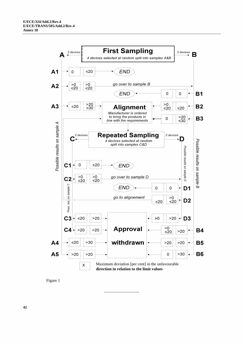
2. First sampling
In the first sampling four retro-reflectors are selected at random. The first
sample of two is marked A, the second sample of two is marked B.
2.1. The conformity is not contested
2.1.1. Following the sampling procedure shown in Figure 1 of this annex the
conformity of mass-produced retro-reflectors shall not be contested if the
deviation of the measured values of the retro-reflectors in the unfavourable
directions are:
2.1.1.1. Sample A
A1: one retro-reflector 0 per cent
one retro-reflector not more than 20 per cent
A2: both retro-reflectors more than 0 per cent
but not more than 20 per cent
go to sample B
2.1.1.2. Sample B
B1: both retro-reflectors 0 per cent
2.2. The conformity is contested
2.2.1. Following the sampling procedure shown in Figure 1 of this annex the
conformity of mass-produced retro-reflectors shall be contested and the
manufacturer requested to make his production meet the requirements
(alignment) if the deviations of the measured values of the retro-reflectors are:
2.2.1.1. Sample A
A3: one retro-reflector not more than 20 per cent
one retro-reflector more than 20 per cent
but not more than 30 per cent

E/ECE/324/Add.2/Rev.4
E/ECE/TRANS/505/Add.2/Rev.4
Annex 18
40
2.2.1.2. Sample B
B2: in the case of A2
one retro-reflector more than 0 per cent
but not more than 20 per cent
one retro-reflector not more than 20 per cent
B3: in the case of A2
one retro-reflector 0 per cent
one retro-reflector more than 20 per cent
but not more than 30 per cent
2.3. Approval withdrawn
Conformity shall be contested and paragraph 9. of this Regulation applied if,
following the sampling procedure in Figure 1 of this annex, the deviations of
the measured values of the retro-reflectors are:
2.3.1. Sample A
A4: one retro-reflector not more than 20 per cent
one retro-reflector more than 30 per cent
A5: both retro-reflectors more than 20 per cent
2.3.2. Sample B
B4: in the case of A2
one retro-reflector more than 0 per cent
but not more than 20 per cent
one retro-reflector more than 20 per cent
B5: in the case of A2
both retro-reflectors more than 20 per cent
B6: in the case of A2
one retro-reflector 0 per cent
one retro-reflector more than 30 per cent
3. Repeated sampling
In the cases of A3, B2, B3 a repeated sampling, third sample C of two retro-
reflectors and fourth sample D of two retro-reflectors, selected from stock
manufactured after alignment, is necessary within two months' time after the
notification.
3.1. The conformity is not contested
3.1.1. Following the sampling procedure shown in Figure 1 of this annex the
conformity of mass-produced retro-reflectors shall not be contested if the
deviations of the measured values of the retro-reflectors are:
3.1.1.1. Sample C
C1: one retro-reflector 0 per cent
one retro-reflector not more than 20 per cent
C2: both retro-reflectors more than 0 per cent
but not more than 20 per cent
go to sample D
E/ECE/324/Add.2/Rev.4
E/ECE/TRANS/505/Add.2/Rev.4
Annex 18
41
3.1.1.2. Sample D
D1: in the case of C2
both retro-reflectors 0 per cent
3.2. The conformity is contested
3.2.1. Following the sampling procedure shown in Figure 1 of this annex the
conformity of mass-produced retro-reflectors shall be contested and the
manufacturer requested to make his production meet the requirements
(alignment) if the deviations of the measured values of the retro-reflectors are:
3.2.1.1. Sample D
D2: in the case of C2
one retro-reflector more than 0 per cent
but not more than 20 per cent
one retro-reflector not more than 20 per cent
3.3. Approval withdrawn
Conformity shall be contested and paragraph 9. of this Regulation applied if,
following the sampling procedure in Figure 1 of this annex, the deviations of
the measured values of the retro-reflectors are:
3.3.1. Sample C
C3: one retro-reflector not more than 20 per cent
one retro-reflector more than 20 per cent
C4: both retro-reflectors more than 20 per cent
3.3.2. Sample D
D3: in the case of C2
one retro-reflector 0 or more than 0 per cent
one retro-reflector more than 20 per cent
4. Resistance to penetration of water
With respect to the verification of the resistance to penetration of water, the
following procedure shall be applied:
One of the retro-reflectors of sample A, after sampling procedure in Figure 1
of this annex, shall be tested according to the procedure described in
paragraph 1. of Annex 8 respectively paragraph 3. of Annex 14 for Class IVA
reflectors.
The retro-reflectors shall be considered as acceptable if the test has been
passed.
However, if the test on sample A is not complied with, the two retro-
reflectors of sample B shall be subjected to the same procedure and both shall
pass the test.
E/ECE/324/Add.2/Rev.4
E/ECE/TRANS/505/Add.2/Rev.4
Annex 18
42
Figure 1
Maximum deviation [per cent] in the unfavourable
direction in relation to the limit values