ageformable panels for commercial aircraft
TRANSCRIPT

25TH INTERNATIONAL CONGRESS OF THE AERONAUTICAL SCIENCES
1
Abstract
The European project “AGEFORM”, in
progress between May 02 until October 05,
aimed to reduce of aircraft acquisition costs,
with the target of contributing to the reduction
of production costs and development time. The
project also aimed to improve the efficiency and
performance of aircraft, by reducing fuel
consumption. This project has developed and
validated cost-effective and flexible
manufacturing methodologies in support of
advanced airframe assembly concepts by
introducing age forming for manufacturing of
structural components. These components
include lower wing skin, fuselage panels,
complex-shaped parts (in particular integrally
stiffened panels), as well as larger complex
integral subassemblies joined by friction stir
welding prior to forming. The project also
enabled the development of advanced age
formable alloys and tempers. All new
developments were demonstrated by real size
fuselage and smaller scale wing demonstrators
elaborated during this project. All actions were
managed considering a future potential
qualification and industrialization of new alloys
using this innovative forming technique. New
material developments, in particular
Aluminium-Lithium alloys, can be integrated in
the approach presented in this paper.
1 General Introduction
The challenge of future materials for airframe applications is to further improve the cost/weight balance compared to current flying solutions (see Fig. 1).
cost
wei
gh
t
20%
20%
cost
wei
gh
t
20%
20%
cost
wei
gh
t
20%
20%
20%
20%
Fig. 1: Illustration of the target for new materials for
airframe applications.
The ageform process allows cost effective and efficient forming of fuselage and wing products. The use of creep forming during aging avoids a lot of manual or, step by step, mechanical forming. Ageforming is also an alternative for shot peen forming which is labor intensive and has quite a strong impact on the environment due to the generation of dust and noise.
Currently, the process is widely applied for products within the 7xxx Aluminium alloy family, such as top wing applications, where in general T7x or T6x tempers are used. As example, all flying Airbus aircraft, as A318, A320, A340 or A380 family, the Ageform process is applied for the TOP wing structure as plates or extrusions in order to obtain very precise product shapes.
The different stages of the ageforming process are illustrated in Fig. 2. The product is introduced into an autoclave after creation of a vacuum between the product and the tooling. The autoclave pressure brings the product into contact with the tooling. Once the thermal cycle, imposed by the artificial aging treatment, is finished, the product is unloaded. Thanks to the tooling optimization, the final curvature can be obtained by taking into account the springback.
AGEFORMABLE PANELS FOR COMMERCIAL AIRCRAFT
F. Eberl*, S. Gardiner**, G. Campanile
(3), G. Surdon
(4), M. Venmans
(5), P. Prangnell
(6)
*Alcan CRV, **Airbus UK, (3)Alenia Aero.,
(4)Dassault Av.,
(5)Sabca,
(6)Univ. of Manchester
Keywords: forming, ageforming, metallic fuselage, laser beam welding, friction stir welding

F. Eberl, S. Gardiner, G. Campanile, G. Surdon, M. Venmans, P. Prangnell
2
agingtemperature
roomtemperature
Fig. 2: Principle of the Ageform process.
Thanks to the Ageform project, the age- or creep-form process could be enlarged to damage tolerant dimensioned airframe parts as bottom wing skin or fuselage skin applications. New aluminum alloys had to be developed in order to be adaptable to the ageform process. After presentation of the pilot materials, used for the process development, the metallurgical principles of the materials and process technology are presented. The material performance of the recent developments focuses in particular on the damage tolerance properties. Once all data acquired, various applications as bottom wing skin, fuselage skin and space applications are illustrated. The specific markets targeted are represented by the various project partners. Airbus represented the commercial aircraft and Dassault the business aircraft applications. Alenia focused on metallic fuselage structures and Sabca on space applications within the Ariane program. Alcan, as the material supplier, was assisted by the metallurgical support given by the University of Manchester.
2 Presentation of the pilot materials used
The recent developments, done within the Ageform project, cover the extension of the creep-form process to damage tolerance dominated products as bottom wing skin or fuselage applications. In order to evaluate the introduction of new materials, current flying alloys as 6056 for fuselage and 7475 for wing applications are used as baseline materials. The technological step proposed in this work is the use of AlCuMg alloys or so-called 2xxx alloys.
The currently flying solutions for damage tolerant applications are 2024 T3 type alloys, using a naturally aged temper. Naturally aged tempers after quenching, so-called T3 tempers, are known for their high toughness performance and therefore widely used for bottom wing skin applications or overall fuselage sheet. In order to apply the ageform process, an artificial ageing treatment is necessary, so that a new metallurgical approach is proposed by introducing the AA2022 alloy, a representative alloy for a shift in the Cu/Mg balance compared to the typical 2024 type alloys (see Fig. 3). The hardening precipitation system is shifted from a mainly S-phase hardening for AA2024 to a θ- and S- phase precipitation system. A more detailed overview is given in the further paragraphs.
Mg-Cu balance
0
1
2
3
4
5
6
0 0.5 1 1.5 2Mg in wt%
Cu
in w
t%
AA2024
AA2022
Fig. 3: Illustration of the Mg/Cu balance for 2xxx type
alloys.
The chemical compositions of the reference alloys used are summarized in the following table Tab. 1. AA6056 Si Fe Cu Mn Mg Cr Zn Ti ZrMin 0.70 0.50 0.40 0.60 0.10Max 1.30 0.50 1.10 1.00 1.20 0.25 0.70 0.20 0.15
AA7475 Si Fe Cu Mn Mg Cr Zn Ti ZrMin 1.20 0.10 1.90 0.18 5.20Max 0.10 0.12 1.90 0.06 2.60 0.25 6.20 0.06 0.05
AA2022 Si Fe Cu Mn Mg Cr Zn Ti ZrMin 4.50 0.10 0.10 0.05Max 0.15 0.20 5.50 0.50 0.45 0.05 0.30 0.15 0.05 Tab. 1: Chemical compositions of the materials used.
In Fig. 4, the strength-toughness balance is presented for all three materials as 4 mm sheet. The toughness data are evaluated on 760 mm wide R-curve samples showing the Kapp value.

3
AGEFORMABLE PANELS FOR COMMERCIAL AIRCRAFT
Strength-toughness balance
7475 T76
2022 T8
6056 T78
90
92
94
96
98
100
102
104
0 100 200 300 400 500TYS(L) in MPa
Kap
p in
MP
a √√ √√m
(76
0) (
T-L
)
Fig. 4: Comparison of the strength-toughness balance
of the pilot materials.
3 Metallurgical principles
3.1 Creep-forming
Very briefly the creep and stress relaxation principles are reminded from the literature. The temperatures used in creep forming of Aluminum alloys lie in the range of 0.4 to 0.5 Tm, where Tm is the melting temperature of Aluminum. Classically, 3 stages, primary, secondary and tertiary creep can be distinguished as shown in Fig. 5 [1]. The second stage is also known as power law creep or steady state creep, where the strain rate is more or less constant. Higher stress or higher temperature accelerate the creep-form process in the same way.
Fig. 5: Typical creep curve (constant stress)
illustrating the 3 stages of creep [1].
For ageform applications, as they are done within this work, a stress relaxation test at constant strain is more appropriate. The higher the temperature used, the higher the stress relaxation as shown in Fig. 6 [2].
Fig. 6: Stress relaxation curves depending on the
temperature applied [2].
The pre-dominant range of creep is stage 2, mainly showing dislocation glide for high stresses or dislocation creep for temperatures higher than 0.33 Tm. Dislocation climb mechanisms by changing from one slip plane to another after encountering an obstacle are part of the dislocation creep. At high temperatures, but for low stresses the diffusion creep becomes the major mechanism. Grain boundary sliding is neglected in this work due to its appearance in stage 3 only. The idea of the Ageform process is to take advantage of the artificial ageing treatment to shape the panel in the same time. The strains imposed for wing or fuselage applications are mostly in the elastic range, so that the elastic strain is transformed into creep strain during the creep-form process as shown in Fig. 7. Depending on the alloys used, the temperature range applied is in a range between 150°C and 200°C, so that the metal does not relax completely and an elastic springback has to be taken into account. Thanks to modern modeling techniques and fine characterization of the materials used, the final shape of the panel to be formed can be predicted. In the following paragraph, the modeling principles are presented.
T73

F. Eberl, S. Gardiner, G. Campanile, G. Surdon, M. Venmans, P. Prangnell
4
Fig. 7: The conversion of elastic strain to creep strain
during a stress relaxation test [2].
3.2 Industrial application of creep-forming –
modeling approach
In order to predict the final shape of an ageformed panel, the creep rate has to be known at each point of the part to be formed. From constant stress creep tests the creep rate,ε& , can be defined by a power law relationship as in the following equation:
)/exp()( RTQk nth −−= σσε&
where σ is the stress, σth is a threshold stress, n is the creep exponent, Q is the activation energy, R is the gas constant, T is the absolute temperature and k is a constant. The evolution of the stress during the ageing cycle can be calculated following the equation,
( ) ( ) dttfRTQ
AEd tvol
nott
t∫∫
+
−−−=00
exp εσσσσ
so that the stress after ageing can be evaluated at each point of the panel. The Young modulus of the material is known, so that the springback can be evaluated and the final shape of the panel predicted. In [3], the determination of the activation energies and the creep exponents is described in detail. The specific values obtained are reminded in Tab. 2. Alloy AA2022 exhibits the greatest metallurgical changes during heat treatment, which explains partly the negative creep stress exponent. The detailed precipitation sequences will be explained in the next paragraph.
alloyactivation energy
low stress
high stress
average
AA2022 170 kJ mol-1 1.3 6.4 4.1
AA6056 139 kJ mol-1 1.3 8.7 5.2
AA7475 134 kJ mol-1 - - -3.0
creep exponent (n)
Tab. 2: Activation energy and creep exponents of the
pilot materials used.
3.3 Metallurgical description of materials
used
Objective of the metallurgical description of the materials used is the - identification of the metallurgical phenomena occurring during ageforming - understanding of the effects of the process parameters and the identification of the optimized process windows (e.g. stress, strain, temperature, time) - resource of stress relaxation constitutive data of the alloys - evaluation/comparison of the ageformability of the alloys - generation of knowledge required to optimize ageformable alloys - metallurgical evaluation of sub-components and demonstrators In the following paragraph stress relaxation data and precipitation mechanisms are summarized. The application for demonstrators will be presented in the corresponding paragraph later in this publication.
3.3.1 Stress relaxation of materials used
In order to evaluate the stress relaxation of the materials used, a constant strain tensile device under ageing temperature has been developed. The stress relaxation during the heat treatment cycle was acquired for all materials used. In Fig. 8 the relaxation curves of 6056, 2022 and 7475, corresponding to their specific ageing treatment, are illustrated. The highest relaxation can be observed for the 2022 alloy before 7475 and 6056. In Tab. 3 the quantitative values of the relaxation and springback are summarized.

5
AGEFORMABLE PANELS FOR COMMERCIAL AIRCRAFT
0
50
100
150
200
0 4 8 12 16 20 24
Time (hrs)
Str
ess
(MP
a)
IS237
6056
7475
2022
Fig. 8: Comparison of relaxation behaviour of 3
materials used at the same initial stress of 200 MPa.
Alloyinitial stress
(MPa)final stress
(MPa)relaxation springback
AA2022 202.5 105.5 48% 53%
AA6056 199.5 142 29% 71%
AA7475 198 123 38% 62% Tab. 3: Evaluation of stress relaxation in springback.
Whereas 6056 and 7475 show classical relaxation behaviour with an exponential decrease of the stress, an inflection can be noticed for the 2022 alloy (see Fig. 9). Due to the hardening precipitation, the material hardens during the ageing treatment, so that the relaxation is slowed down after about 6 hours treatment. This behaviour can be avoided if the material is pre-aged. During the pre-ageing the entire hardening precipitation is initiated and only precipitation coarsening is remaining. Nevertheless, the relaxation is decreased as illustrated in Fig. 10 by comparing the entire creep-relaxation treatment with a 12h at 173°C pre-aged sample. The relaxation potential has been reduced from 48% to 39%.
0
20
40
60
80
100
120
140
160
180
0 4 8 12 16 20 24
Time (hrs)
Str
ess
(MP
a), H
ard
nes
s (H
v)
Relaxation Curve
Ageing Curve
Inflection!
Fig. 9: Illustration of the relaxation curve of 2022 at
an initial stress of 150 MPa.
0
40
80
120
160
200
0 4 8 12 16 20 24
Time (hrs)
Stre
ss (M
Pa)
No Pre age
Pre age 12h@173°C
95 MPa
80 MPa
Fig. 10: 2022 relaxation curves of a standard aged and
a pre-aged sample.
In Fig. 11 the sensitivity of relaxation behaviour to the initial stress is illustrated for the 7475 alloy. The dislocation creep mostly activated at these stresses and temperatures is extremely sensitive to stress, so that higher stresses lead to higher relaxation behaviour than lower ones. This representation allows also to determine the limit stress under which no creep-forming could be practiced anymore, at around 30% of the initial yield strength of the material [3].
0
50
100
150
200
250
300
0 4 8 12 16 20 24
Time (hrs)
Str
ess
(MP
a)
197 MPa (0.56)
140.5 MPa (0.40)
252.5 MPa (0.72)
295 MPa (0.84)
Fig. 11: Stress relaxation curves related to different
stress levels (in parenthesis the ratio to the yield
strength in the TAF temper).
Another important aspect for the industrialization of the ageform process is the processing time. In Fig. 12 the ageing temperature is increased up to 200°C by respecting the equivalent treatment time for the reference procedure. At higher temperatures better relaxation behaviour can be observed. At temperatures higher than 190°C, the inflection of the relaxation curve (see Fig. 9) is masked by the higher relaxation rate [3]. A balance

F. Eberl, S. Gardiner, G. Campanile, G. Surdon, M. Venmans, P. Prangnell
6
between more and quicker relaxation and metallurgical needs for a finer hardening precipitation has to be defined. Ageing treatments at lower temperatures lead to a finer precipitation and therefore improved material properties.
0
20
40
60
80
100
120
140
160
0 5 10 15 20
Time (hrs)
Str
ess
(MP
a)
173°C
180°C
185°C
190°C
200°C
Fig. 12: Comparison of relaxation behaviour of
AA2022 for equivalent ageing treatments.
A last aspect, which has to be taken into account for the optimization of the ageform process, is the volume change of the products to be artificially aged. In Fig. 13 the 3 alloys characterized are compared. The major difference is the expansion of 2022 compared to the contraction of 7475. The laboratory tensile creep tests showed a higher relaxation rate for the 2022 alloy (see Fig. 8), but if the volume change is taken into account, both alloys show a similar relaxation rate [4].
Measured length change after heat treatment cycle
-0.04
-0.03
-0.02
-0.01
0
0.01
0.02
0.03
0.04
0.05
IS237 6056 7475
Str
ain
(%)
2022 74756056
Fig. 13: Volume change of 2022, 6056 and 7475 during
the respective heat treatment, measured by
dilatometry.
Another possibility to compare the “ageformability” of various alloys by avoiding the impact of the volume change is the use of a laboratory or semi-industrial bending facility usable under artificial ageing conditions. Three tool radiuses were developed at the University of Manchester (see Fig. 14). The data obtained coincide perfectly with the semi-industrial data generated by the airframers, as Dassault, Airbus and Sabca. In Fig. 15 the ageform performance is represented as the final panel radius obtained (normalized by the panel thickness) as a function of the imposed bending strain. The semi-industrial data were generated on large coupons by using an experimental set-up as shown in Fig. 2.
Fig. 14: Laboratory bending facility with different tool
radiuses and their corresponding imposed strain εεεε.
0
1000
2000
3000
4000
5000
6000
7000
0.00% 0.20% 0.40% 0.60% 0.80%
Max bending strain loading
Rpa
nel /
thic
knes
s 2022
0
1000
2000
3000
4000
5000
6000
7000
0.000% 0.200% 0.400% 0.600% 0.800%
Max bending strain
Rpa
nel /
thic
knes
s 7475
0.800%
Dassault, Airbus, Sabca data
Dassault, Airbus, Sabca data
Laboratory data (UoM)Laboratory data (UoM)
Fig. 15: Evaluation of creep-relaxation performance of
7475 and 2022 after bending test by representing the
thickness normalized final panel radius as a function
of the imposed bending strain.
In summary, the 3 pilot materials selected for the Ageform project have been characterized in detail considering their creep-form performance. A specific developed tensile device allowed to register the stress-relaxation in real time during the ageing treatment. Thanks to the tensile test constitutive data have been acquired for a potential modeling approach for future ageform process development. Preliminary process
7
AGEFORMABLE PANELS FOR COMMERCIAL AIRCRAFT
windows for applying the ageform process could be defined. Volume changes of the various alloys have been taken into account in order to compare the alloy performances directly by using the tensile tests. An alternative semi-industrial process, the so-called bending test, has been developed for a quick material evaluation.
3.3.2 Characterization of the hardening
precipitation during ageforming
The ageform process combines the forming and artificial ageing step within the fabrication of the aerospace panel. In order to optimize this modified processing sequence, the hardening precipitation mechanisms have to be understood. In [7], [8] and [9], the hardening precipitation of the 6056, 7475 and 2022 alloy was observed using Transmission Electron Microscopy (TEM) and Small Angle X-ray Scattering (SAXS). The aged under zero stress samples were compared to aged under stress samples. Already in [6] the precipitation sequence of the 6056 alloy is presented: SSSS α→ GP zones → ″β(needle) → ′β(rod)→ β(Mg2Si)
→ λ′ or Q′ → λ or Q (Al5Cu2Mg’Si6 )
(SSSS-Super Saturated Solid Solution; GP-Guiner
Preston)
Thanks to the copper content, a second hardening phase complementarily to the Mg2Si phase, the so-called λ phase precipitates. In all investigations done, no difference between static and creep ageing could be detected. The 2022 alloy, part of the AlCuMg system, follows the precipitation sequence mentioned in [7]: SSSS α → GP zones → θ′′ → θ′ → θ′(Al2Cu)
→ Ω; → S′; → S (Al2CuMg); → σ (Al5Cu6Mg2)
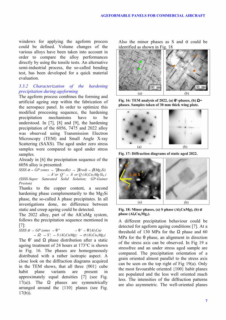
The θ’ and Ω phase distribution after a static ageing treatment of 24 hours at 173°C is shown in Fig. 16. The phases are homogeneously distributed with a rather isotropic aspect. A close look on the diffraction diagrams acquired in the TEM shows, that all three 001 cube habit plane variants are present in approximately equal densities [7] (see Fig. 17(a)). The Ω phases are symmetrically arranged around the 110 planes (see Fig. 17(b)).
Also the minor phases as S and σ could be identified as shown in Fig. 18
(a)
(b)
Fig. 16: TEM analysis of 2022, (a) θθθθ’-phases, (b) Ω−Ω−Ω−Ω− phases. Samples taken of 30 mm thick wing plate.
(a)
(b)
Fig. 17: Diffraction diagrams of static aged 2022.
(a)
(b)
Fig. 18: Minor phases, (a) S phase (Al2CuMg), (b) σσσσ phase (Al5Cu6Mg2).
A different precipitation behaviour could be detected for ageform ageing conditions [7]. At a threshold of 130 MPa for the Ω phase and 60 MPa for the θ phase, an alignment in direction of the stress axis can be observed. In Fig 19 a stressfree and an under stress aged sample are compared. The precipitation orientation of a grain oriented almost parallel to the stress axis can be seen on the top right of Fig 19(a). Only the most favourable oriented 100 habit planes are populated and the less well oriented much less. The intensities of the diffraction patterns are also asymmetric. The well-oriented planes

F. Eberl, S. Gardiner, G. Campanile, G. Surdon, M. Venmans, P. Prangnell
8
show much higher intensity than the less well-oriented.
[010]
[001]
[010]
[010]
[001]
[010]
[001]
[010] (a)
[010]
[001]
[010] σσσσ[010]
[001]
[010] σσσσ
(b)
Fig 19: Comparison of 2022 under static and dynamic
ageing conditions, (a) no stress, (b) under stress aged
(202 MPa): alignment of θθθθ and ΩΩΩΩ phase.
After a detailed analysis of the static properties (strength, anisotropy), no significant difference could be detected for the statically and dynamically aged samples. The third material evaluated is part the 7xxx series, the so-called 7475. It is a well-known alloy for specific fuselage and wing applications. Its precipitation sequence is reminded in the following [7]: SSSS α → GP zones → ′η → η (MgZn2)
Detailed analysis of the precipitation evolution during the T73 ageing treatment is reported in [8]. Compared to 2xxx alloys, no precipitation alignment has been found for 7xxx alloys. A detailed analysis of the T73 over-ageing treatment of 7475 under 245 MPa tensile stress showed a precipitation alignment at the end of the first stage (see Fig. 20), which disappeared once the T73 treatment is finished. The control sample did not show any of these phenomena. Following [8], it can be distinguished between spherical GP-I and plate morphological GP-II zones, which precipitate only in the stress-aged sample with a preference for the 111 plane. In 2xxx alloys, the θ’ and Ω phases have a negative misfit, so that they prefer to precipitate on compressive planes during tensile load in order to reduce the strain energy contribution to the energy barrier for nucleation [7, 8]. GP-II
zones contain mainly Zn and Cu, so that they have a larger misfit than the GP-I phases, which explains their presence in the stress-aged samples. Once the second stage temperature is reached, the GP zones partly dissolve for η’ precipitation, which are again spherical. A slight difference in size of the η’ phases could be measured at the final temper. In the stress-aged samples an average particle size of 68 Å was measured compared to 62 Å for the conventional aged sample. The imposed stress slightly increases the aging kinetics, which leads to a slight decrease of the static properties (~6%). 0.01h@108°C 4h@108°C 4h@108°C+
24h@160°C
Fig. 20: SAXS results from conventionally and stress-
aged AA7475 (const. σσσσ=245 MPa) at different stages of
the T73 temper applied.
In summary, three pilot materials were characterized in detail with an established comparison between stress-aged and conventionally aged control samples. No differences could be detected for the 6056 alloy. The AA2022 showed precipitation alignment for the stress-aged samples, but no impact on the static properties, neither the anisotropy of the product could be detected. In the AA7475 alloy, an evolution of the precipitation alignment at intermediate stages of the ageing treatment could be detected. The final product does not show any alignment anymore, but the stress-aged sample had slightly lower static properties due to an accelerated kinetics under stress. This slight property impact can easily be re-adapted, by a slight change of the ageing treatment duration if considered as necessary.

9
AGEFORMABLE PANELS FOR COMMERCIAL AIRCRAFT
This type of correction is not necessary for AA2022 as shown in Fig. 21. The kinetics of 2xxx alloys in general is much slower in the overaged temper. The strength of AA2022 remains much longer time stable in the duration of the treatment compared to 7475, where a continuous decrease of the properties is noticed for the longer ageing treatments.
time
stre
ng
th
2022
7475
time
stre
ng
th
2022
7475
time
stre
ng
th
2022
7475t
Fig. 21: Principle of ageing kinetics of AA2022 and
AA7475.
As neither static properties, nor the anisotropy are impacted by the stress-ageing, the damage tolerance properties have to be confirmed, in particular for the applications, which were targeted, as the bottom wing skin and the fuselage panels.
3.4 Evaluation of damage tolerance
properties of ageformed panels
One major objective of the Ageform project was the evaluation of the damage tolerance properties of ageformable alloys for damage tolerance dominated products. As previously mentioned, current baselines for fuselage or bottom wing applications are 2xxx alloys in the naturally aged T3 temper. The use of the ageforming process needs a switch to a T6x or T7x temper for the 6xxx or 7xxx and T8x for the 2xxx alloys. In the following, experiments validating the ageform process for damage tolerant products and the increase compared to the current flying baseline will be illustrated using the previous mentioned pilot products. For bottom wing skin applications formed coupons were tested using the Kahn test for samples creep-formed under tensile and compression. In order to avoid heterogeneities of the chemical composition, all testing was
done within one bend sample. The Kahn test was done in L-T and T-L direction with 2 samples per test. Compressive and tensile loaded samples were characterized as shown in Fig. 22. The samples, which were aged conventionally, were taken in the outside of the bending sample (see also Fig. 22).
76 mm wide
760 mm long
Top view
Side view
B BM
T
20 mm thick
C
L-T samplesT-L samplesKahn test sample
Fig. 22: Sampling in a bent coupon (760 x 78 x 20 mm)
for toughness tests using Kahn test samples.
The Kahn test results are presented in Fig. 23 as a function of the opening energy Eop or the resistance Re in MPa. No difference between the conventional and stress-aged sample could be noticed (see Fig. 24).
4
6
8
10
12
14
0C 0T C Tsample
Eo
p in
J
2022, T-L
2022, L-T
7475, T-L
7475, L-T155
160
165
170
175
180
185
0C 0T C Tsample
Re
in M
Pa
Fig. 23: Kahn test results on 7475 and 2022 coupons.
0: no stress, C: compression, T: tensile.
For fuselage applications the validation testing for curved fuselage panels has to be done on 760 mm wide test panels, which is currently not possible to be tested in the curved shape. An “inverse forming” experiment was done by combining the roll- and ageforming process in order to obtain a flat ageformed panel (see Fig. 25). A 3.2 mm and 6 mm thick AA2022 sheet were rollformed to a small and a large fuselage radius in the T3 temper [10]. The rollformed panels were respectively put in a 1m and 2m radius ageforming tool and creepformed in the autoclave device following the procedure illustrated in Fig. 2. The formed panels were

F. Eberl, S. Gardiner, G. Campanile, G. Surdon, M. Venmans, P. Prangnell
10
completely flat again, so that standard R-curve testing could be done on the “inverse” ageformed panels with their corresponding control panels.
Roll forming
Ageforming
Sample loading
in autoclave
Fig. 24: Process sequence of an “inverse” creep-
formed fuselage panel.
In Fig. 25, the R-curves obtained on the control and the ageformed samples are shown. Neither for the 3.2 mm sheet formed on the 1m radius tooling, nor for the 6 mm sheet formed on the 2m radius tooling a significant difference in the R-curve behaviour could be detected.
R-Curves CCT760 (L-T)Ageforming effect
50
70
90
110
130
150
170
190
0 20 40 60∆∆∆∆aeff (mm)
Kr
(MP
a √√ √√m
)
2022clad T8 th 3.2 ref
2022clad T8 ageformed 3.2 mm (R 1 m)
2022clad T8 th 6 mm ref
2022clad T8 ageformed 6 mm (R 2 m)
Fig. 25: R-curves of “inverse” formed fuselage panels
compared to conventional aged control panels. Test
samples: 760 mm wide CCT samples.
In summary, although alignment of hardening precipitates of the AA2022 alloy could be detected by TEM or SAXS observations (see previous paragraph), no impact on the damage tolerance behaviour could be noticed. Kahn experiments for wing applications, and real size W760 R-curve testing were done on ageformed fuselage panels. The ageformed samples were compared to control samples and no difference could be detected. In other words, the ageform process does not affect the damage tolerance properties and all material properties can be acquired after a standard ageing treatment on flat samples. Stable damage tolerance behaviour could be demonstrated and even improved material property balances could be reached for
the 2022 ageformable alloy compared to a 2024 T3 baseline (see Fig. 26)
Strength-toughness balance
110
120
130
140
150
160
350 370 390 410 430 450
strength: TYS(L) in MPa
dam
age
tole
ran
ce:
Kap
p(L
-T)
in
MP
a √√ √√m
(W
760)
baseline: 2024 T3
2022 T8
8%8%
16%16%
Fig. 26: Strength-toughness balance of 2022 T8
compared to the 2024 T3 baseline. Evaluated on a
fuselage sheet product with a panel width of 760 mm.
3.5 Ageform process for aerospace
applications
The consortium of the ageform project consisted of various airframe manufacturers as Airbus UK, Alenia Aeronautica, Dassault Aviation and Sabca. Their applications developed within the Ageform program will be illustrated in the following.
3.5.1 Ageformed bottom wing skin for
commercial aircraft
The currently flying bottom wing skins are formed by using a shot peening process. The forming cycles are long and many times manual correction steps have to be added. The use of the Ageform process would allow to more automation of the forming process and even eliminate the dirty and noisy shot peening process. The major difficulty is the complex form of the bottom wing skin panels. Special features as manholes and overthicknesses have to be taken into account in the design of the ageform tooling. Within the project the metallurgy of bend coupons in AA2022 and AA7475 has been studied in detail and the know-how learnt in the characterization workpackage has been applied before the elaboration of a bottom wing demonstrator panel.

11
AGEFORMABLE PANELS FOR COMMERCIAL AIRCRAFT
A 20 mm coupon was formed on a tool with a 3180 mm radius. Five samples through the 20 mm thickness have been taken and analysed using the TEM and SAXS methods. In the AA2022 alloy the previous discussed alignment of the θ’ phases can be confirmed. Looking closer on the TEM diffraction patterns (see Fig. 27), the diffraction dots on the 111 plane representing the Ω phases have the same intensity on all samples, so that no alignment of the Ω phases can be confirmed even if the maximum stresses on the outer or inner line of the bend coupon reach the ±185 MPa, which is higher than the previous determined threshold stress for the alignment of the Ω phases. Quick relaxation at the beginning of the treatment might be the reason why no alignment could be found for the Ω phases [9].
Fig. 27: TEM analysis through the thickness of a bend
coupon in AA2022 alloy.
As previously mentioned for the AA7475 no precipitation alignment could be detected in the coupon samples. Using the SAXS technique, the average hardening precipitation radius was measured. Close to the neutral axis of the bend coupon the radius of the stress free aged samples could be confirmed. A larger particle radius was found for the compressive loaded samples as shown in Fig. 28. This can be explained by the residual Bauschinger effect due to the stretching operation after quenching of the wing plates, which leads to a faster relaxation in the compressive area of the coupon.
30
40
50
60
70
0 1 2 3 4 5 6
Position
g(r
) n
m
Bend sample
Top Bottom
No Stress
Fig. 28: Mean particle radius of ηηηη’ precipitation in AA7475.
Once all modelling and experimental data acquired, a demonstrator panel was elaborated as shown in Fig. 29. A specimen containing two manholes and various overthicknesses between rib 42 and 49 was selected. Unfortunately, the final results of the forming process were not available at publishing date.
Fig. 29: Design of bottom wing demonstrator.
3.5.2 Ageforming of an integral fuselage panel
containing FSW joints and LBW stringers
Alenia Aeronautica elaborated a real size bottom fuselage panel of a long-range commercial aircraft using a new assembling sequence thanks to the Ageform process. This one-to-one scale demonstrator contained a longitudinal friction stir welded (FSW) joint of machined panels containing pockets and thickness variations. The stringers were laser beam welded (LBW) on the skin. The advantage of the Ageform process is that all machining and assembling steps can be done on flat panels. The forming process is done on the all finished panel. The processing sequence is presented in Fig. 30 [10]. After a step-by-step development from forming of coupons over sub-components and finally to a real size demonstrator (see Fig. 31), technological and metallurgical difficulties as thickness variations, LBW and FSW joints could be managed, so that the predicted form of
F. Eberl, S. Gardiner, G. Campanile, G. Surdon, M. Venmans, P. Prangnell
12
the final panel could be obtained as shown in Fig. 32.
Flat panelsupplied in T3 condition
Chemical/mechanicalmilling
Pickling of skin and stringers FSW of 2 panels
LBW of stringers to skin
Ageforming Non-destructiveinspection of welds
Fig. 30: Processing sequence of a fuselage panel
containing a FSW joint and LBW stringers.
Fig. 31: Ageformed real size fuselage panel including
pocketing, FSW and LBW stringers.
y = 95,257x-1,0799
0
500
1000
1500
2000
2500
3000
0,00 0,10 0,20 0,30 0,40
Bending Strain % (th/2/Rtool)
Rp
anel
/ th
B.M.Full scale demonstratorSub-Component 1Sub-Component 2
Fig. 32: Evaluation of the forming performance of the
full-scale demonstrator compared to the base material
and sub-component forming.
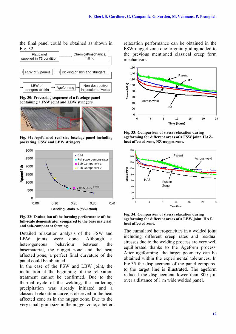
Detailed relaxation analysis of the FSW and LBW joints were done. Although a heterogeneous behaviour between the basematerial, the nugget zone and the heat affected zone, a perfect final curvature of the panel could be obtained. In the case of the FSW and LBW joint, the inclination at the beginning of the relaxation treatment cannot be confirmed. Due to the thermal cycle of the welding, the hardening precipitation was already initiated and a classical relaxation curve is observed in the heat affected zone as in the nugget zone. Due to the very small grain size in the nugget zone, a better
relaxation performance can be obtained in the FSW nugget zone due to grain gliding added to the previous mentioned classical creep form mechanisms.
0
20
40
60
80
100
120
140
160
0 4 8 12 16 20 24
Time (hours)S
tre
ss (
MP
a)
Standard
HAZ
TW
NZ
Parent
Across weld
0
20
40
60
80
100
120
140
160
0 4 8 12 16 20 24
Time (hours)S
tre
ss (
MP
a)
Standard
HAZ
TW
NZ
Parent
Across weld
Fig. 33: Comparison of stress relaxation during
ageforming for different areas of a FSW joint. HAZ-
heat affected zone, NZ-nugget zone.
0
20
40
60
80
100
120
140
160
0 4 8 12 16 20 24
Time (hrs)
Str
ess
(MP
a)
HAZ
NZ
TW
Standard
Parent
HAZFusion Zone
Across weld
Fig. 34: Comparison of stress relaxation during
ageforming for different areas of a LBW joint. HAZ-
heat affected zone.
The cumulated heterogeneities in a welded joint including different creep rates and residual stresses due to the welding process are very well equilibrated thanks to the Ageform process. After ageforming, the target geometry can be obtained within the experimental tolerances. In Fig.35 the displacement of the panel compared to the target line is illustrated. The ageform reduced the displacement lower than 800 µm over a distance of 1 m wide welded panel.

13
AGEFORMABLE PANELS FOR COMMERCIAL AIRCRAFT
-2-1012345
-500 -300 -100 100 300 500width in mm
dis
pla
cem
ent
in m
m after welding
after ageforming
Fig.35: Decrease of distortion of a LBW panel after
ageforming.
In summary, a new processing sequence of fuselage panels could be illustrated within the Ageform program. Complex features as FSW and LBW could be integrated and a higher performance panel could be obtained with even a cost reduced assembling procedure.
3.5.3 Ageformed integral bottom wing skin for
business aircraft
In contrast to other airframe manufacturers, Dassault Aviation uses a mechanical clamping technique during the ageform cycle. The panel is clamped between a male and a female tooling (see Fig. 36). The loading is done at room temperature and the heat treatment cycle can be done in a standard ageing furnace. Various experiments within the project including integrally machined sub-components (see Fig. 37) demonstrated that the loading and the tooling procedure do not affect the final shape of the panel. For the right choice of the tooling a mechanical clamping or an autoclave approach are equivalent.
Fig. 36: Mechanical clamping tool for the ageform
process.
Fig. 37: Optimization of the ageform process by using
integrally machined coupons (dim.: 475 x 475 mm).
The target product is an integrally machined bottom wing skin panel containing a strongly deformed break reaching a plastic strain close to 4%. Numerical simulations were done in order to localize and evaluate the strain within the so-called break-panel. Once the critical areas were identified, as previously, the microstructure was analysed using the TEM technique. Again, the precipitation alignment in the thickness of the integrally machined stringer could be confirmed (see Fig. 38).
Fig. 38: Evaluation of the microstructure of a Dassault
break panel. Detection of the maximum strain using
finite element simulations.
After optimization of the forming parameters and validation of the tool curvature calculated by finite element simulation, a reduced scale demonstrator could be obtained as shown in Fig. 39.
Fig. 39: Dassault break panel after ageforming.
In conclusion, the ageform process can be applied for strongly deformed integral stiffened panels. For higher deformation, even entering in the plastic domain, the 2022 seems to be more adapted than the 7475 due to the accelerated ageing kinetics in the stronger deformed area and therefore a stronger heterogeneity of properties is expected (see also Fig. 21).

F. Eberl, S. Gardiner, G. Campanile, G. Surdon, M. Venmans, P. Prangnell
14
3.5.4 Ageforming of booster panels for the
Ariane program
Various panels of the Ariane booster (see Fig. 40) were considered to be ageformed using an autoclave cycle as illustrated in Fig. 2. Currently the panels are step-by-step press-formed and the introduction of the ageform process would allow a more automated and more efficient process.
Fig. 40: Illustration of potential panels for Ariane
booster applications.
Cylindrical and spherical tools were elaborated as shown in Fig. 41. Complex panels containing non parallel stringers and holes were formed and the target curvature could be reached.
(a) (b)
Fig. 41: (a) cylindrical and (b) spherical tooling.
Fig. 42: Spherical ageformed panels containing special
features as non parallel stringers or holes.
4 Outlook
Within the Ageform project the feasibility of the creep-form process was demonstrated on real airframe panels. New damage tolerant materials have been developed for the application of the ageform process. In particular, new AlCuMg
alloys as 2022 are very well adapted for this process. For next generation alloys including the 3rd generation of AlCuLi alloys, the ageform process is perfectly adapted. The Ageform project allowed also to develop a 4 point bending test for the ranking of ageformable alloys. In Fig. 43 various results of this test are represented. The curvature obtained is represented as a function of the imposed strain. Materials without any springback would be superposed to the red line. The previously discussed 2022 alloy is rather well situated compared to the 6056 alloy. The next generation of the 2022 alloy is the so-called 2139 alloy, a silver containing AlCuMg alloy, which shows a slightly higher springback, but a strongly increased strength-toughness balance as shown in Fig. 44. First results of the recent 2198 alloy, an AlCuLi alloy, were generated and a very good performance could be obtained, close to the level of the 2022 alloy. From the process optimization point of view, it might be interesting to reduce the cycle time of the autoclave. The 2022 alloy was pre-aged in a standard furnace during 8 and 12 hours.
0.00%
0.05%
0.10%
0.15%
0.20%
0.25%
0.0% 0.1% 0.2% 0.3% 0.4% 0.5%
max bending strain loading
max
ben
din
g s
trai
n a
fter
fo
rmin
g
no springbackAlcan, 2022Alcan, 2022 (8h pre-aged)Alcan, 2022 (12h pre-aged)6056Alcan, 2139 T851Alcan, 2198
sample
upper 2 points
lower 2 points
Fig. 43: Evaluation of ageformable alloys using a 4
point bending test.
The remaining ageing treatment was done in the creep-forming condition. The springback increased, so that a balance between cycle time and ageform performance has to be defined.

15
AGEFORMABLE PANELS FOR COMMERCIAL AIRCRAFT
2024 T351
6156 T651
7475 T7651
2139 T851
2198 T851
2022 T851
100
110
120
130
140
150
160
170
180
230 330 430 530CYS(LT) (MPa)
Kap
p(T
-L)
(MP
a √√ √√m
)
Fig. 44: Strength-toughness balance of materials
evaluated within Ageform and next generation
materials including AlCuLi alloys.
5 Conclusions
Within the Ageform project, the creep-form process was adapted for damage tolerant applications as the bottom wing skin or fuselage panels. New damage tolerant alloys were developed and entirely characterized during each step of the process. Higher strength-toughness balances could be reached compared to the current flying baseline as 2024 T3. The increased properties, in particular the R-curve behaviour were verified after ageforming. No difference in properties could be detected compared to standard aged samples, so that in future standard testing procedures can be applied for new ageformable alloys. An entire testing scenario has been set-up within the project, so that for future developments the scenario only has to be adapted, so that the time to market for future developments can be extremely shortened. By looking on the current evolution of the product metallurgy, 3rd generation AlCuLi alloys progress quickly. Thanks to the new developments, these alloys seem to be perfectly adapted for the application of the Ageform process. Within the permanent challenge to reduce the weight-cost balance, the Ageform process allows to progress in the most favourable
direction. New design concepts, in particular monolithic structures, can be realized using the advantages of creep-forming in a cost effective way.
Acknowledgements
This research was carried out under the project reference G5RD-CT-2002-00743 “Ageformable Panels for Commercial Aircraft” in the European Commission’s fifth framework programme.
References
[1] Dieter G.E. Mechanical Metallurgy. S.I. Metric Edn., McGraw-Hill, London, 1988, p. 439.
[2] Honeycombe R. W. K., The Plastic Deformation of
Metals. 2nd Ed., Edward Arnold, London, 1984, p358
[3] Robey R.F., Prangnell P.B., Dif R., A Comparison of
the Stress Relaxation Behaviour of Three Aluminium
Aerospace Alloys for use in Age Forming
Applications. ICAA9, Brisbane Au, pp 124-131, 2004.
[4] Robey R.F., Prangnell P.B., communication within the Ageform consortium, 2005.
[5] Prangnell P.B., communication within the Ageform consortium, 2005.
[6] Dif R., Bes B., Ehrström J.C., Sigli C., Warner T.J., Lassince P., Ribes H., Understanding and Modelling
the Mechanical and Corrosion Properties of 6056 for
Aerospace Applications, Mat. Sc. Forum, Vols. 331-337, pp 1613-1618, 2000.
[7] Bakavos D., Prangnell P.B., Dif R., A comparison of
the effects of ageforming on the precipitation
behaviour in 2xxx, 6xxx and 7xxx aerospace alloys, ICAA9, Brisbane Au, pp 124-131, 2004.
[8] Bakavos D., Prangnell P.B., Bes B., Eberl F., Grossmann J.G., Microstructural interactions during
stress ageing a 7475 aerospace alloy, ICAA10, Vancouver, 2006 (to be published)
[9] Bakavos D., Prangnell P.B., Eberl F., Gardiner S., Through thickness microstructural gradients in 7475
and 2022 ageformed bend coupons, ICAA10, Vancouver, 2006 (to be published)
[10] Campanile G., Galota V., Eberl F., Age creep forming of welded integral structures in 6056 and 2022 aluminium alloy, Aeromat, Orlando, USA, 2005.
[11] Surdon G., Gratiot E., Eberl F., Age-forming development using the new AA2022 for bottom wing application, , Aeromat, Orlando, USA, 2005.