ag inverter micromaster 440 - europower.com.hk · inverter micromaster 440 4/2 description ... and...
TRANSCRIPT
Siemens DA 51.2 · 2007/2008 4/1
4
InverterMICROMASTER 440
4/2 Description
4/4 Circuit diagrams
4/6 Technical data
4/9 Selection and ordering data
4/12 Options
4/26 Dimension drawings
© Siemens AG 2007
4/2 Siemens DA 51.2 · 2007/2008
MICROMASTER 440
4
Application Design Main characteristics
Easy, guided start-up Modular construction al-
lows maximum configura-tion flexibility
Six programmable isolated digital inputs
Two scaleable analog in-puts (0 V to 10 V, 0 mA to 20 mA) can also be used as a 7th/8th digital input
Two programmable analog outputs (0 mA to 20 mA)
Three programmable relay outputs (30 V DC/5 A resis-tive load; 250 V AC/2A in-ductive load)
Low-noise motor operation thanks to high pulse fre-quencies, adjustable (ob-serve derating if necessary)
Complete protection for motor and inverter.
Options (overview)
EMC filter, Class A/B LC filter and sinusoidal filter Line commutating chokes Output chokes Gland plates
Basic Operator Panel (BOP) for parameterizing the inverter
Plain text Advanced Opera-tor Panel (AOP) with multi-language display
Plain text Asian Advanced Operator Panel (AAOP) with Chinese and English display
Plain text Cyrillic Advanced Operator Panel (CAOP) with Cyrillic, German and English display
Communication modules– PROFIBUS– DeviceNet– CANopen
Pulse encoder evaluation module
PC connection kits Mounting kits for installing
the operator panels in the control cabinet doors
PC start-up tools execut-able under Windows 98 and NT/2000/ME/XP Professional
TIA integration with Drive ES.
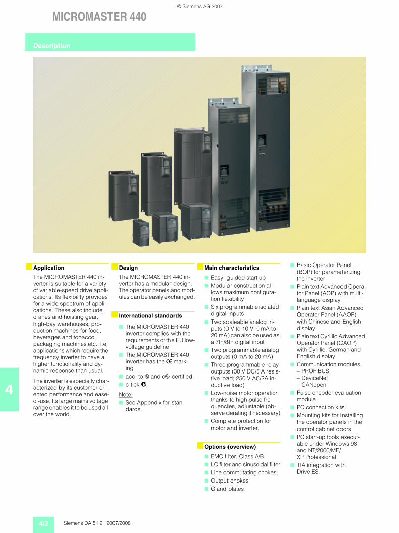
The MICROMASTER 440 in-verter is suitable for a variety of variable-speed drive appli-cations. Its flexibility provides for a wide spectrum of appli-cations. These also include cranes and hoisting gear, high-bay warehouses, pro-duction machines for food, beverages and tobacco, packaging machines etc.; i.e. applications which require the frequency inverter to have a higher functionality and dy-namic response than usual.
The inverter is especially char-acterized by its customer-ori-ented performance and ease-of-use. Its large mains voltage range enables it to be used all over the world.
The MICROMASTER 440 in-verter has a modular design. The operator panels and mod-ules can be easily exchanged.
International standards
The MICROMASTER 440 inverter complies with the requirements of the EU low-voltage guideline
The MICROMASTER 440 inverter has the > mark-ing
acc. to u and cu certified c-tick
Note: See Appendix for stan-
dards.
Description
© Siemens AG 2007
Siemens DA 51.2 · 2007/2008 4/3
MICROMASTER 440
4
Mechanical features Performance features Protection features
Modular design Operating temperature
0.12 kW to 75 kW:–10 °C to +50 °C(+14 °F to +122 °F)90 kW to 200 kW:0 °C to +40 °C(+32 °F to +104 °F)
Compact housing as a re-sult of high power density
Easy cable connection, mains and motor connec-tions are separated for opti-mum electromagnetic com-patibility
Detachable operator panels
Screwless control terminals on detachable I/O board.
Latest IGBT technology Digital microprocessor
control High-quality Vector Control
system Flux Current Control (FCC)
for improved dynamic re-sponse and optimized mo-tor control
Linear V/f characteristic Quadratic V/f characteristic Multipoint characteristic
(programmable V/f charac-teristic)
Torque control Flying restart Slip compensation Automatic restart following
mains failure or fault User-definable function
blocks for logic and arith-metic operations
Kinetic buffering Positioning ramp down High-grade PID controller
for simple internal process control (autotuning)
Programmable accelera-tion/deceleration, 0 s to 650 s
Ramp smoothing Fast Current Limit (FCL) for
trip-free operation Fast, repeatable digital in-
put response time Fine adjustment using two
high-resolution 10-bit ana-log inputs
Compound braking for con-trolled rapid braking
Integrated brake chopper (for 0.12 kW to 75 kW invert-ers)
Four skip frequencies Removable “Y” capacitor
for use on IT systems (with non-grounded mains sup-plies, the “Y” capacitor must be removed and an output choke installed).
Overload capability– CT mode
0.12 kW to 75 kW:Overload current 1.5 x rated output current (i.e. 150 % overload capabili-ty) for 60 s, cycle time 300 s, and 2 x rated out-put current (i.e. 200 % overload capability) for 3 s, cycle time 300 s90 kW to 200 kW:Overload current 1.36 x rated output current (i.e. 136 % overload capabili-ty) for 57 s, cycle time 300 s, and 1.6 x rated out-put current (i.e. 160 % overload capability) for 3 s, cycle time 300 s
– VT mode5.5 kW to 90 kW:Overload current 1.4 x rated output current (i.e. 140 % overload capabili-ty) for 3 s, and 1.1 x rated output current (i.e. 110 % overload capability) for 60 s, cycle time 300 s110 kW to 250 kW:Overload current 1.5 x rated output current (i.e. 150 % overload capabili-ty) for 1 s, and 1.1 x rated output current (i.e. 110 % overload capability) for 59 s, cycle time 300 s
Overvoltage/undervoltage protection
Inverter overtemperature protection
Special direct connection for PTC or KTY to protect the motor
Earth fault protection Short-circuit protection I2t motor thermal protection Locked motor protection Stall prevention Parameter interlock.
Description
© Siemens AG 2007
4/4 Siemens DA 51.2 · 2007/2008
MICROMASTER 440
4
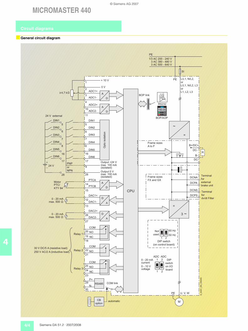
General circuit diagram
=
3 ~
A
D
A
D
PE
PE U, V, W
M
1 2
ADC ADC1 2
A/
D
A/
D
+ 10 V
0 V
NPN
PNP
DCNA
DCNS
DCPS
DCPA
DC-
~
=
ADC1+
ADC2+
ADC2-
ADC1-
DIN1
DIN2
DIN3
DIN4
DIN5
DIN6
PTCA
PTCB
DAC1+
DAC2+
DAC2-
DAC1-
P+
N-
COM
COM
COM
NC
NO
NO
NO
NC
1
2
3
4
10
11
5
6
7
8
16
17
9
28
14
15
12
13
26
27
29
30
20
18
19
25
23
24
22
21
0 - 20 mAmax. 500
0 - 20 mAmax. 500
≥
0 - 20 mA
0 - 10 V
5
6
7
8
16
17
28
DIN1
DIN2
DIN3
DIN4
DIN5
DIN6
24 V
+
_
A
D
A
D
RS485
PE
SI
1 2
60 Hz
50 Hz
Ω
A
D
150.00
BOP/AOP
RS232
~
=
CPU
1/3 AC 200 - 240 V3 AC 380 - 480 V3 AC 500 - 640 V
B+/DC+
DC-
B-R
4,7 k
L/L1, N/L2,
L/L1, N/L2, L3
L1, L2, L3
or
Motor
30 V DC/5 A (resistive load)
250 V AC/2 A (inductive load)
Frame sizes
A to F
Frame sizes
FX and GX
max. 100 mA(isolated)
Output +24 V
max. 100 mA(isolated)
Output 0 V
current
voltage
automatic
Terminal
for
external
brake unit
Not
used
DIP switch
(on control board)
DIP
switch
on I/O
board
Op
to iso
latio
n
G_
DA
51
_E
N_
05
02
4h
or
or
Terminal
for
dv/dt Filter
COM link
CB
option
Relay 3
Relay 2
Relay 1
24 V external
BOP link
PTC/
KTY 84
Circuit diagrams
© Siemens AG 2007
Siemens DA 51.2 · 2007/2008 4/5
MICROMASTER 440
4
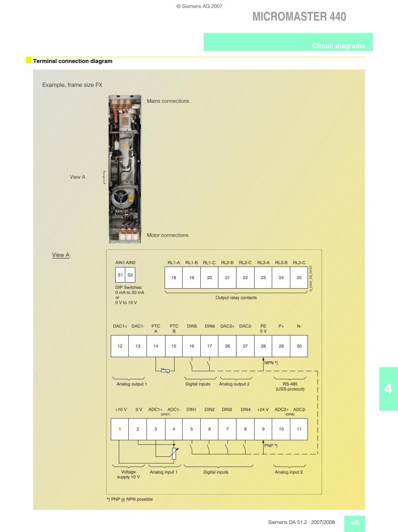
Terminal connection diagram
22 24 252318 20 2119
27 29 302818 17 261612 14 1513
8 10 1196 751 3 42
RL1-A RL2-BRL1-B RL1-C RL2-C RL3-A RL3-B RL3-C
DAC1+ DAC1- P+ N-DIN5 DIN6 DAC2+ DAC2-PTCA
PTCB
PE0 V
+10 V 0 V ADC1+ ADC1- DIN1 DIN2 DIN3 DIN4 ADC2+ ADC2-+24 V
S2S1
(DIN7) (DIN8)
AIN1 AIN2
NPN *)
PNP *)
DIP Switches:0 mA to 20 mA or0 V to 10 V
Output relay contacts
Analog output 1 Digital inputs Analog output 2 RS-485(USS-protocol)
Voltagesupply 10 V
Digital inputsAnalog input 1 Analog input 2
*) PNP or NPN possible
G_D
A51
_EN
_051
07
View A
Motor connections
Example, frame size FX
View A
Mains connections
Circuit diagrams
© Siemens AG 2007
4/6 Siemens DA 51.2 · 2007/2008
MICROMASTER 440
4
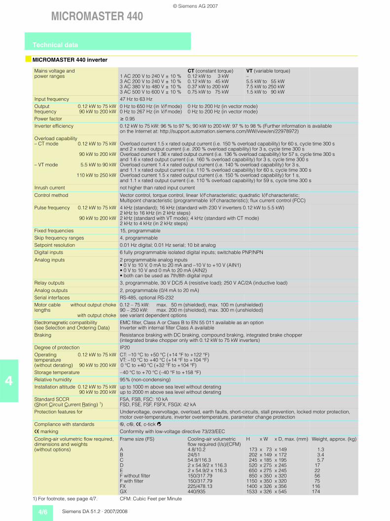
MICROMASTER 440 inverter
Mains voltage and power ranges 1 AC 200 V to 240 V ± 10 %
3 AC 200 V to 240 V ± 10 %3 AC 380 V to 480 V ± 10 %3 AC 500 V to 600 V ± 10 %
CT (constant torque)0.12 kW to 3 kW0.12 kW to 45 kW0.37 kW to 200 kW0.75 kW to 75 kW
VT (variable torque)–5.5 kW to 55 kW7.5 kW to 250 kW1.5 kW to 90 kW
Input frequency 47 Hz to 63 HzOutput 0.12 kW to 75 kWfrequency 90 kW to 200 kW
0 Hz to 650 Hz (in V/f mode)0 Hz to 267 Hz (in V/f mode)
0 Hz to 200 Hz (in vector mode)0 Hz to 200 Hz (in vector mode)
Power factor 0.95Inverter efficiency 0.12 kW to 75 kW: 96 % to 97 %; 90 kW to 200 kW: 97 % to 98 % (Further information is available
on the Internet at: http://support.automation.siemens.com/WW/view/en/22978972)Overload capability– CT mode 0.12 kW to 75 kW
90 kW to 200 kW
– VT mode 5.5 kW to 90 kW
110 kW to 250 kW
Overload current 1.5 x rated output current (i.e. 150 % overload capability) for 60 s, cycle time 300 s and 2 x rated output current (i.e. 200 % overload capability) for 3 s, cycle time 300 s Overload current 1.36 x rated output current (i.e. 136 % overload capability) for 57 s, cycle time 300 s and 1.6 x rated output current (i.e. 160 % overload capability) for 3 s, cycle time 300 s Overload current 1.4 x rated output current (i.e. 140 % overload capability) for 3 s,and 1.1 x rated output current (i.e. 110 % overload capability) for 60 s, cycle time 300 s Overload current 1.5 x rated output current (i.e. 150 % overload capability) for 1 s,and 1.1 x rated output current (i.e. 110 % overload capability) for 59 s, cycle time 300 s
Inrush current not higher than rated input current
Control method Vector control, torque control, linear V/f characteristic; quadratic V/f characteristic; Multipoint characteristic (programmable V/f characteristic); flux current control (FCC)
Pulse frequency 0.12 kW to 75 kW
90 kW to 200 kW
4 kHz (standard); 16 kHz (standard with 230 V inverters 0.12 kW to 5.5 kW)2 kHz to 16 kHz (in 2 kHz steps)2 kHz (standard with VT mode); 4 kHz (standard with CT mode)2 kHz to 4 kHz (in 2 kHz steps)
Fixed frequencies 15, programmableSkip frequency ranges 4, programmableSetpoint resolution 0.01 Hz digital; 0.01 Hz serial; 10 bit analogDigital inputs 6 fully programmable isolated digital inputs; switchable PNP/NPN
Analog inputs 2 programmable analog inputs• 0 V to 10 V, 0 mA to 20 mA and –10 V to +10 V (AIN1)• 0 V to 10 V and 0 mA to 20 mA (AIN2)• both can be used as 7th/8th digital input
Relay outputs 3, programmable, 30 V DC/5 A (resistive load); 250 V AC/2A (inductive load)
Analog outputs 2, programmable (0/4 mA to 20 mA)Serial interfaces RS-485, optional RS-232Motor cable without output chokelengths
with output choke
0.12 – 75 kW: max. 50 m (shielded), max. 100 m (unshielded)90 – 250 kW: max. 200 m (shielded), max. 300 m (unshielded)see variant dependent options
Electromagnetic compatibility (see Selection and Ordering Data)
EMC filter, Class A or Class B to EN 55 011 available as an optionInverter with internal filter Class A available
Braking Resistance braking with DC braking, compound braking, integrated brake chopper (integrated brake chopper only with 0.12 kW to 75 kW inverters)
Degree of protection IP20Operating 0.12 kW to 75 kWtemperature(without derating) 90 kW to 200 kW
CT: –10 °C to +50 °C (+14 °F to +122 °F)VT: –10 °C to +40 °C (+14 °F to +104 °F)0 °C to +40 °C (+32 °F to +104 °F)
Storage temperature –40 °C to +70 °C (–40 °F to +158 °F)Relative humidity 95% (non-condensing)Installation altitude 0.12 kW to 75 kW
90 kW to 200 kWup to 1000 m above sea level without deratingup to 2000 m above sea level without derating
Standard SCCR (Short Circuit Current Rating) 1)
FSA, FSB, FSC: 10 kAFSD, FSE, FSF, FSFX, FSGX: 42 kA
Protection features for Undervoltage, overvoltage, overload, earth faults, short-circuits, stall prevention, locked motor protection, motor over-temperature, inverter overtemperature, parameter change protection
Compliance with standards u, cu, >, c-tick
> marking Conformity with low-voltage directive 73/23/EEC
Cooling-air volumetric flow required, dimensions and weights (without options)
Frame size (FS)
A BCDE F without filterF with filterFXGX
Cooling-air volumetric flow required (l/s)/(CFM) 4.8/10.224/5154.9/116.32 x 54.9/2 x 116.32 x 54.9/2 x 116.3150/317.79150/317.79225/478.13440/935
H x W x D, max. (mm)
173 x 73 x 149202 x 149 x 172245 x 185 x 195520 x 275 x 245650 x 275 x 245850 x 350 x 320
1150 x 350 x 3201400 x 326 x 3561533 x 326 x 545
Weight, approx. (kg)
1.33.45.7
17225675
116174
1) For footnote, see page 4/7. CFM: Cubic Feet per Minute
Technical data
© Siemens AG 2007
Siemens DA 51.2 · 2007/2008 4/7
MICROMASTER 440
4
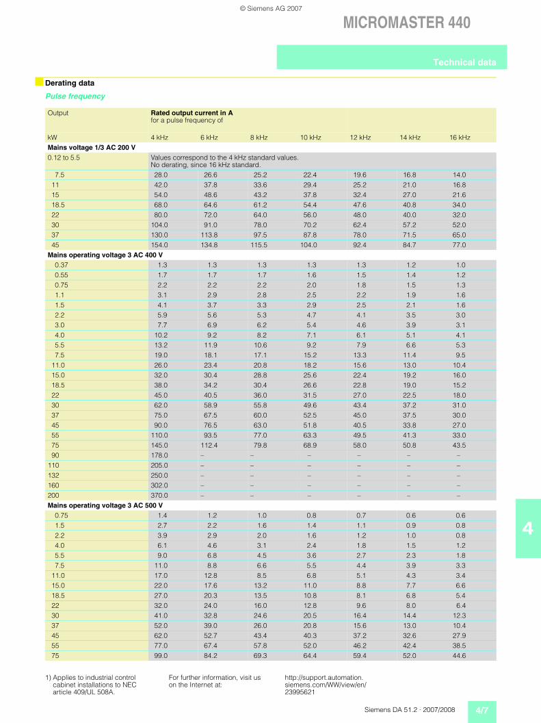
Derating data
Pulse frequency
Output Rated output current in Afor a pulse frequency of
kW 4 kHz 6 kHz 8 kHz 10 kHz 12 kHz 14 kHz 16 kHzMains voltage 1/3 AC 200 V0.12 to 5.5 Values correspond to the 4 kHz standard values.
No derating, since 16 kHz standard.7.5 28.0 26.6 25.2 22.4 19.6 16.8 14.0
11 42.0 37.8 33.6 29.4 25.2 21.0 16.815 54.0 48.6 43.2 37.8 32.4 27.0 21.618.5 68.0 64.6 61.2 54.4 47.6 40.8 34.022 80.0 72.0 64.0 56.0 48.0 40.0 32.030 104.0 91.0 78.0 70.2 62.4 57.2 52.037 130.0 113.8 97.5 87.8 78.0 71.5 65.045 154.0 134.8 115.5 104.0 92.4 84.7 77.0
Mains operating voltage 3 AC 400 V0.37 1.3 1.3 1.3 1.3 1.3 1.2 1.00.55 1.7 1.7 1.7 1.6 1.5 1.4 1.20.75 2.2 2.2 2.2 2.0 1.8 1.5 1.31.1 3.1 2.9 2.8 2.5 2.2 1.9 1.61.5 4.1 3.7 3.3 2.9 2.5 2.1 1.62.2 5.9 5.6 5.3 4.7 4.1 3.5 3.03.0 7.7 6.9 6.2 5.4 4.6 3.9 3.14.0 10.2 9.2 8.2 7.1 6.1 5.1 4.15.5 13.2 11.9 10.6 9.2 7.9 6.6 5.37.5 19.0 18.1 17.1 15.2 13.3 11.4 9.5
11.0 26.0 23.4 20.8 18.2 15.6 13.0 10.415.0 32.0 30.4 28.8 25.6 22.4 19.2 16.018.5 38.0 34.2 30.4 26.6 22.8 19.0 15.222 45.0 40.5 36.0 31.5 27.0 22.5 18.030 62.0 58.9 55.8 49.6 43.4 37.2 31.037 75.0 67.5 60.0 52.5 45.0 37.5 30.045 90.0 76.5 63.0 51.8 40.5 33.8 27.055 110.0 93.5 77.0 63.3 49.5 41.3 33.075 145.0 112.4 79.8 68.9 58.0 50.8 43.590 178.0 – – – – – –
110 205.0 – – – – – –132 250.0 – – – – – –160 302.0 – – – – – –200 370.0 – – – – – –Mains operating voltage 3 AC 500 V
0.75 1.4 1.2 1.0 0.8 0.7 0.6 0.61.5 2.7 2.2 1.6 1.4 1.1 0.9 0.82.2 3.9 2.9 2.0 1.6 1.2 1.0 0.84.0 6.1 4.6 3.1 2.4 1.8 1.5 1.25.5 9.0 6.8 4.5 3.6 2.7 2.3 1.87.5 11.0 8.8 6.6 5.5 4.4 3.9 3.3
11.0 17.0 12.8 8.5 6.8 5.1 4.3 3.415.0 22.0 17.6 13.2 11.0 8.8 7.7 6.618.5 27.0 20.3 13.5 10.8 8.1 6.8 5.422 32.0 24.0 16.0 12.8 9.6 8.0 6.430 41.0 32.8 24.6 20.5 16.4 14.4 12.337 52.0 39.0 26.0 20.8 15.6 13.0 10.445 62.0 52.7 43.4 40.3 37.2 32.6 27.955 77.0 67.4 57.8 52.0 46.2 42.4 38.575 99.0 84.2 69.3 64.4 59.4 52.0 44.6
1) Applies to industrial control cabinet installations to NEC article 409/UL 508A.
For further information, visit us on the Internet at:
http://support.automation.siemens.com/WW/view/en/23995621
Technical data
© Siemens AG 2007

4/8 Siemens DA 51.2 · 2007/2008
MICROMASTER 440
4
Derating data (continued)
Operating temperature
Installation altitude above sea level
30
60
-10 0 700
20
40
20
80
100
10
%
605040 °C
CTVT
70
50
Rat
ed o
utpu
t cur
rent
Operating temperature
G_DA51_EN_05026c
Inverter 0.12 kW to 75 kW Inverter 90 kW to 200 kW
2000
60
0 40000
20
40
80
DA51-5018c
100
1000
%
3000 m
Rat
ed o
utpu
t cur
rent
Operational altitude
A
Inverter 0.12 kW to 75 kW Inverter 90 kW to 200 kW
Permissible output currentin % of the rated output current
2000
60
0 40000
20
40
80
DA51-5019b
100
1000
%
3000 m
77
Mai
ns v
olta
ge
Operational altitude
A
2000
60
0 40000
20
40
80
DA51-5019b
100
1000
%
3000 m
77
Mai
ns v
olta
ge
Operational altitude
A
Inverter 0.12 kW to 75 kW Inverter 90 kW to 200 kW
Permissible mains voltagein % of the max. possible mains voltage
Technical data
© Siemens AG 2007
Siemens DA 51.2 · 2007/2008 4/9
MICROMASTER 440
4
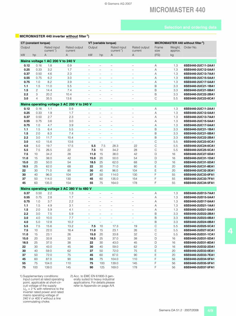
MICROMASTER 440 inverter without filter 2)
CT (constant torque) VT (variable torque) MICROMASTER 440 without filter 2)Output Rated input
current 1)Rated output current
Output Rated input current 1)
Rated output current
Frame size
Weight, approx.
Order No.
kW hp A A kW hp A A (FS) kg
Mains voltage 1 AC 200 V to 240 V0.12 0.16 1.8 0.9 – – – – A 1.3 6SE6440-2UC11-2AA10.25 0.33 3.2 1.7 – – – – A 1.3 6SE6440-2UC12-5AA10.37 0.50 4.6 2.3 – – – – A 1.3 6SE6440-2UC13-7AA10.55 0.75 6.2 3.0 – – – – A 1.3 6SE6440-2UC15-5AA10.75 1.0 8.2 3.9 – – – – A 1.3 6SE6440-2UC17-5AA11.1 1.5 11.0 5.5 – – – – B 3.3 6SE6440-2UC21-1BA11.5 2 14.4 7.4 – – – – B 3.3 6SE6440-2UC21-5BA12.2 3 20.2 10.4 – – – – B 3.3 6SE6440-2UC22-2BA13.0 4 35.5 13.6 – – – – C 5.5 6SE6440-2UC23-0CA1
Mains operating voltage 3 AC 200 V to 240 V0.12 0.16 1.1 0.9 – – – – A 1.3 6SE6440-2UC11-2AA10.25 0.33 1.9 1.7 – – – – A 1.3 6SE6440-2UC12-5AA10.37 0.50 2.7 2.3 – – – – A 1.3 6SE6440-2UC13-7AA10.55 0.75 3.6 3.0 – – – – A 1.3 6SE6440-2UC15-5AA10.75 1.0 4.7 3.9 – – – – A 1.3 6SE6440-2UC17-5AA11.1 1.5 6.4 5.5 – – – – B 3.3 6SE6440-2UC21-1BA11.5 2.0 8.3 7.4 – – – – B 3.3 6SE6440-2UC21-5BA12.2 3.0 11.7 10.4 – – – – B 3.3 6SE6440-2UC22-2BA13.0 4.0 15.6 13.6 – – – – C 5.5 6SE6440-2UC23-0CA14.0 5.0 19.7 17.5 5.5 7.5 28.3 22 C 5.5 6SE6440-2UC24-0CA15.5 7.5 26.5 22 7.5 10 34.2 28 C 5.5 6SE6440-2UC25-5CA17.5 10 34.2 28 11.0 15 38.0 42 D 16 6SE6440-2UC27-5DA1
11.0 15 38.0 42 15.0 20 50.0 54 D 16 6SE6440-2UC31-1DA115.0 20 50.0 54 18.5 25 62.0 68 D 16 6SE6440-2UC31-5DA118.5 25 62.0 68 22 30 71.0 80 E 20 6SE6440-2UC31-8EA122 30 71.0 80 30 40 96.0 104 E 20 6SE6440-2UC32-2EA130 40 96.0 104 37 50 114.0 130 F 55 6SE6440-2UC33-0FA137 50 114.0 130 45 60 135.0 154 F 55 6SE6440-2UC33-7FA145 60 135.0 154 55 75 164.0 178 F 55 6SE6440-2UC34-5FA1
Mains operating voltage 3 AC 380 V to 480 V0.37 0.50 2.2 1.3 – – – – A 1.3 6SE6440-2UD13-7AA10.55 0.75 2.8 1.7 – – – – A 1.3 6SE6440-2UD15-5AA10.75 1.0 3.7 2.2 – – – – A 1.3 6SE6440-2UD17-5AA11.1 1.5 4.9 3.1 – – – – A 1.3 6SE6440-2UD21-1AA11.5 2.0 5.9 4.1 – – – – A 1.3 6SE6440-2UD21-5AA12.2 3.0 7.5 5.9 – – – – B 3.3 6SE6440-2UD22-2BA13.0 4.0 10.0 7.7 – – – – B 3.3 6SE6440-2UD23-0BA14.0 5.0 12.8 10.2 – – – – B 3.3 6SE6440-2UD24-0BA15.5 7.5 15.6 13.2 7.5 10 17.3 19 C 5.5 6SE6440-2UD25-5CA17.5 10 22.0 18.4 11.0 15 23.1 26 C 5.5 6SE6440-2UD27-5CA1
11.0 15 23.1 26 15.0 20 33.8 32 C 5.5 6SE6440-2UD31-1CA115.0 20 33.8 32 18.5 25 37.0 38 D 16 6SE6440-2UD31-5DA118.5 25 37.0 38 22 30 43.0 45 D 16 6SE6440-2UD31-8DA122 30 43.0 45 30 40 59.0 62 D 16 6SE6440-2UD32-2DA130 40 59.0 62 37 50 72.0 75 E 20 6SE6440-2UD33-0EA137 50 72.0 75 45 60 87.0 90 E 20 6SE6440-2UD33-7EA145 60 87.0 90 55 75 104.0 110 F 56 6SE6440-2UD34-5FA155 75 104.0 110 75 100 139.0 145 F 56 6SE6440-2UD35-5FA175 100 139.0 145 90 125 169.0 178 F 56 6SE6440-2UD37-5FA1
1) Supplementary conditions: Input current at rated operating point, applicable at short-cir-cuit voltage of the supply Usc = 2 % with reference to the inverter rated power and rated mains operating voltage of 240 V or 400 V without a line commutating choke.
2) Acc. to EMC EN 61800-3 gen-erally suited to heavy industrial applications. For details please refer to Appendix on page A/4.
Selection and ordering data
© Siemens AG 2007
4/10 Siemens DA 51.2 · 2007/2008
MICROMASTER 440
4
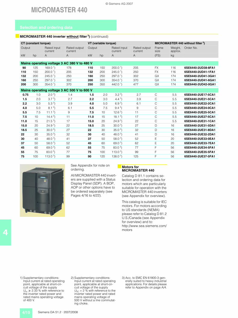
MICROMASTER 440 inverter without filter 3) (continued)
CT (constant torque) VT (variable torque) MICROMASTER 440 without filter 3)
Output Rated input current
Rated output current
Output Rated input current
Rated output current
Frame size
Weight, approx.
Order No.
kW hp A A kW hp A A (FS) kg
Mains operating voltage 3 AC 380 V to 480 V90 125 169.0 1) 178 110 150 200.0 1) 205 FX 116 6SE6440-2UD38-8FA1
110 150 200.0 1) 205 132 200 245.0 1) 250 FX 116 6SE6440-2UD41-1FA1132 200 245.0 1) 250 160 250 297.0 1) 302 GX 174 6SE6440-2UD41-3GA1160 250 297.0 1) 302 200 300 354.0 1) 370 GX 174 6SE6440-2UD41-6GA1200 300 354.0 1) 370 250 350 442.0 1) 477 GX 174 6SE6440-2UD42-0GA1
Mains operating voltage 3 AC 500 V to 600 V0.75 1.0 2.0 2) 1.4 1.5 2.0 3.2 2) 2.7 C 5.5 6SE6440-2UE17-5CA11.5 2.0 3.7 2) 2.7 2.2 3.0 4.4 2) 3.9 C 5.5 6SE6440-2UE21-5CA12.2 3.0 5.3 2) 3.9 4.0 5.0 6.9 2) 6.1 C 5.5 6SE6440-2UE22-2CA14.0 5.0 8.1 2) 6.1 5.5 7.5 9.4 2) 9 C 5.5 6SE6440-2UE24-0CA15.5 7.5 11.1 2) 9 7.5 10 12.6 2) 11 C 5.5 6SE6440-2UE25-5CA17.5 10 14.4 2) 11 11.0 15 18.1 2) 17 C 5.5 6SE6440-2UE27-5CA1
11.0 15 21.5 2) 17 15.0 20 24.9 2) 22 C 5.5 6SE6440-2UE31-1CA115.0 20 24.9 2) 22 18.5 25 30.0 2) 27 D 16 6SE6440-2UE31-5DA118.5 25 30.0 2) 27 22 30 35.0 2) 32 D 16 6SE6440-2UE31-8DA122 30 35.0 2) 32 30 40 48.0 2) 41 D 16 6SE6440-2UE32-2DA130 40 48.0 2) 41 37 50 58.0 2) 52 E 20 6SE6440-2UE33-0EA137 50 58.0 2) 52 45 60 69.0 2) 62 E 20 6SE6440-2UE33-7EA145 60 69.0 2) 62 55 75 83.0 2) 77 F 56 6SE6440-2UE34-5FA155 75 83.0 2) 77 75 100 113.0 2) 99 F 56 6SE6440-2UE35-5FA175 100 113.0 2) 99 90 120 138.0 2) 125 F 56 6SE6440-2UE37-5FA1
See Appendix for note on ordering.
All MICROMASTER 440 invert-ers are supplied with a Status Display Panel (SDP). A BOP, AOP or other options have to be ordered separately (see Pages 4/16 to 4/22).
Motors for MICROMASTER 440
Catalog D 81.1 contains se-lection and ordering data for motors which are particularly suitable for operation with the MICROMASTER 440 inverters (see Appendix for overview).
This catalog is suitable for IEC motors. For motors according to US standards (NEMA) please refer to Catalog D 81.2 U.S./Canada (see Appendix for overview) and to: http://www.sea.siemens.com/motors
1) Supplementary conditions: Input current at rated operating point, applicable at short-cir-cuit voltage of the supply Usc 2.33 % with reference to the inverter rated power and rated mains operating voltage of 400 V.
2) Supplementary conditions:Input current at rated operating point, applicable at short-cir-cuit voltage of the supply USC = 2 % with reference to the inverter rated power and rated mains operating voltage of 500 V without a line commutat-ing choke.
3) Acc. to EMC EN 61800-3 gen-erally suited to heavy industrial applications. For details please refer to Appendix on page A/4.
Selection and ordering data
© Siemens AG 2007
Siemens DA 51.2 · 2007/2008 4/11
MICROMASTER 440
4
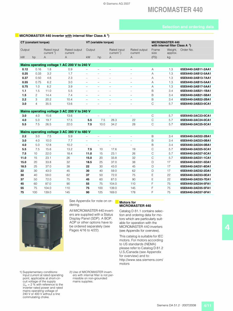
MICROMASTER 440 inverter with internal filter Class A 2)
CT (constant torque) VT (variable torque) MICROMASTER 440 with internal filter Class A 2)
Output Rated input current 1)
Rated output current
Output Rated input current 1)
Rated output current
Frame size
Weight, approx.
Order No.
kW hp A A kW hp A A (FS) kg
Mains operating voltage 1 AC 200 V to 240 V0.12 0.16 1.8 0.9 – – – – A 1.3 6SE6440-2AB11-2AA10.25 0.33 3.2 1.7 – – – – A 1.3 6SE6440-2AB12-5AA10.37 0.50 4.6 2.3 – – – – A 1.3 6SE6440-2AB13-7AA10.55 0.75 6.2 3.0 – – – – A 1.3 6SE6440-2AB15-5AA10.75 1.0 8.2 3.9 – – – – A 1.3 6SE6440-2AB17-5AA11.1 1.5 11.0 5.5 – – – – B 3.4 6SE6440-2AB21-1BA11.5 2 14.4 7.4 – – – – B 3.4 6SE6440-2AB21-5BA12.2 3 20.2 10.4 – – – – B 3.4 6SE6440-2AB22-2BA13.0 4 35.5 13.6 – – – – C 5.7 6SE6440-2AB23-0CA1
Mains operating voltage 3 AC 200 V to 240 V3.0 4.0 15.6 13.6 – – – – C 5.7 6SE6440-2AC23-0CA14.0 5.0 19.7 17.5 5.5 7.5 28.3 22 C 5.7 6SE6440-2AC24-0CA15.5 7.5 26.5 22.0 7.5 10.0 34.2 28 C 5.7 6SE6440-2AC25-5CA1
Mains operating voltage 3 AC 380 V to 480 V2.2 3.0 7.5 5.9 – – – – B 3.4 6SE6440-2AD22-2BA13.0 4.0 10.0 7.7 – – – – B 3.4 6SE6440-2AD23-0BA14.0 5.0 12.8 10.2 – – – – B 3.4 6SE6440-2AD24-0BA15.5 7.5 15.6 13.2 7.5 10 17.6 19 C 5.7 6SE6440-2AD25-5CA17.5 10 22.0 18.4 11.0 15 23.1 26 C 5.7 6SE6440-2AD27-5CA1
11.0 15 23.1 26 15.0 20 33.8 32 C 5.7 6SE6440-2AD31-1CA115.0 20 33.8 32 18.5 25 37.0 38 D 17 6SE6440-2AD31-5DA118.5 25 37.0 38 22 30 43.0 45 D 17 6SE6440-2AD31-8DA122 30 43.0 45 30 40 59.0 62 D 17 6SE6440-2AD32-2DA130 40 59.0 62 37 50 72.0 75 E 22 6SE6440-2AD33-0EA137 50 72.0 75 45 60 87.0 90 E 22 6SE6440-2AD33-7EA145 60 87.0 90 55 75 104.0 110 F 75 6SE6440-2AD34-5FA155 75 104.0 110 75 100 139.0 145 F 75 6SE6440-2AD35-5FA175 100 139.0 145 90 125 169.0 178 F 75 6SE6440-2AD37-5FA1
See Appendix for note on or-dering.
All MICROMASTER 440 invert-ers are supplied with a Status Display Panel (SDP). A BOP, AOP or other options have to be ordered separately (see Pages 4/16 to 4/22).
Motors for MICROMASTER 440
Catalog D 81.1 contains selec-tion and ordering data for mo-tors which are particularly suit-able for operation with the MICROMASTER 440 inverters (see Appendix for overview).
This catalog is suitable for IEC motors. For motors according to US standards (NEMA) please refer to Catalog D 81.2 U.S./Canada (see Appendix for overview) and to: http://www.sea.siemens.com/motors
1) Supplementary conditions: Input current at rated operating point, applicable at short-cir-cuit voltage of the supply Usc = 2 % with reference to the inverter rated power and rated mains operating voltage of 240 V or 400 V without a line commutating choke.
2) Use of MICROMASTER invert-ers with internal filter is not per-missible on non-grounded mains supplies.
Selection and ordering data
© Siemens AG 2007
4/12 Siemens DA 51.2 · 2007/2008
MICROMASTER 440
4Technical data
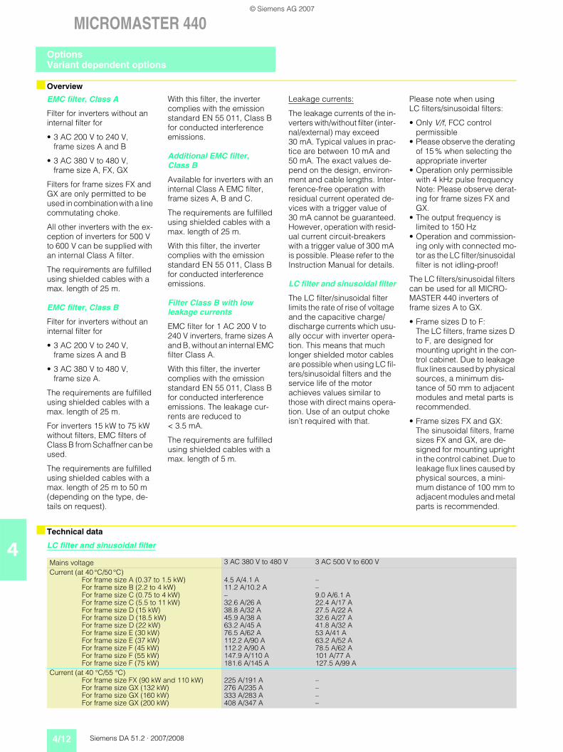
LC filter and sinusoidal filter
Overview
EMC filter, Class A
Filter for inverters without an internal filter for
• 3 AC 200 V to 240 V, frame sizes A and B
• 3 AC 380 V to 480 V, frame size A, FX, GX
Filters for frame sizes FX and GX are only permitted to be used in combination with a line commutating choke.
All other inverters with the ex-ception of inverters for 500 V to 600 V can be supplied with an internal Class A filter.
The requirements are fulfilled using shielded cables with a max. length of 25 m.
EMC filter, Class B
Filter for inverters without an internal filter for
• 3 AC 200 V to 240 V, frame sizes A and B
• 3 AC 380 V to 480 V, frame size A.
The requirements are fulfilled using shielded cables with a max. length of 25 m.
For inverters 15 kW to 75 kW without filters, EMC filters of Class B from Schaffner can be used.
The requirements are fulfilled using shielded cables with a max. length of 25 m to 50 m (depending on the type, de-tails on request).
With this filter, the inverter complies with the emission standard EN 55 011, Class B for conducted interference emissions.
Additional EMC filter, Class B
Available for inverters with an internal Class A EMC filter, frame sizes A, B and C.
The requirements are fulfilled using shielded cables with a max. length of 25 m.
With this filter, the inverter complies with the emission standard EN 55 011, Class B for conducted interference emissions.
Filter Class B with low leakage currents
EMC filter for 1 AC 200 V to 240 V inverters, frame sizes A and B, without an internal EMC filter Class A.
With this filter, the inverter complies with the emission standard EN 55 011, Class B for conducted interference emissions. The leakage cur-rents are reduced to < 3.5 mA.
The requirements are fulfilled using shielded cables with a max. length of 5 m.
Leakage currents:
The leakage currents of the in-verters with/without filter (inter-nal/external) may exceed 30 mA. Typical values in prac-tice are between 10 mA and 50 mA. The exact values de-pend on the design, environ-ment and cable lengths. Inter-ference-free operation with residual current operated de-vices with a trigger value of 30 mA cannot be guaranteed.However, operation with resid-ual current circuit-breakers with a trigger value of 300 mA is possible. Please refer to the Instruction Manual for details.
LC filter and sinusoidal filter
The LC filter/sinusoidal filter limits the rate of rise of voltage and the capacitive charge/discharge currents which usu-ally occur with inverter opera-tion. This means that much longer shielded motor cables are possible when using LC fil-ters/sinusoidal filters and the service life of the motor achieves values similar to those with direct mains opera-tion. Use of an output choke isn’t required with that.
Please note when using LC filters/sinusoidal filters:
• Only V/f, FCC control permissible
• Please observe the derating of 15 % when selecting the appropriate inverter
• Operation only permissible with 4 kHz pulse frequency Note: Please observe derat-ing for frame sizes FX and GX.
• The output frequency is limited to 150 Hz
• Operation and commission-ing only with connected mo-tor as the LC filter/sinusoidal filter is not idling-proof!
The LC filters/sinusoidal filters can be used for all MICRO-MASTER 440 inverters of frame sizes A to GX.
• Frame sizes D to F:The LC filters, frame sizes D to F, are designed for mounting upright in the con-trol cabinet. Due to leakage flux lines caused by physical sources, a minimum dis-tance of 50 mm to adjacent modules and metal parts is recommended.
• Frame sizes FX and GX:The sinusoidal filters, frame sizes FX and GX, are de-signed for mounting upright in the control cabinet. Due to leakage flux lines caused by physical sources, a mini-mum distance of 100 mm to adjacent modules and metal parts is recommended.
Mains voltage 3 AC 380 V to 480 V 3 AC 500 V to 600 VCurrent (at 40 °C/50 °C)
For frame size A (0.37 to 1.5 kW)For frame size B (2.2 to 4 kW)For frame size C (0.75 to 4 kW)For frame size C (5.5 to 11 kW)For frame size D (15 kW)For frame size D (18.5 kW)For frame size D (22 kW)For frame size E (30 kW)For frame size E (37 kW)For frame size F (45 kW)For frame size F (55 kW)For frame size F (75 kW)
4.5 A/4.1 A –11.2 A/10.2 A –– 9.0 A/6.1 A32.6 A/26 A 22.4 A/17 A38.8 A/32 A 27.5 A/22 A45.9 A/38 A 32.6 A/27 A63.2 A/45 A 41.8 A/32 A76.5 A/62 A 53 A/41 A112.2 A/90 A 63.2 A/52 A112.2 A/90 A 78.5 A/62 A147.9 A/110 A 101 A/77 A181.6 A/145 A 127.5 A/99 A
Current (at 40 °C/55 °C)For frame size FX (90 kW and 110 kW)For frame size GX (132 kW)For frame size GX (160 kW)For frame size GX (200 kW)
225 A/191 A –276 A/235 A –333 A/283 A –408 A/347 A –
OptionsVariant dependent options
© Siemens AG 2007
Siemens DA 51.2 · 2007/2008 4/13
MICROMASTER 440
4
Technical data (continued)
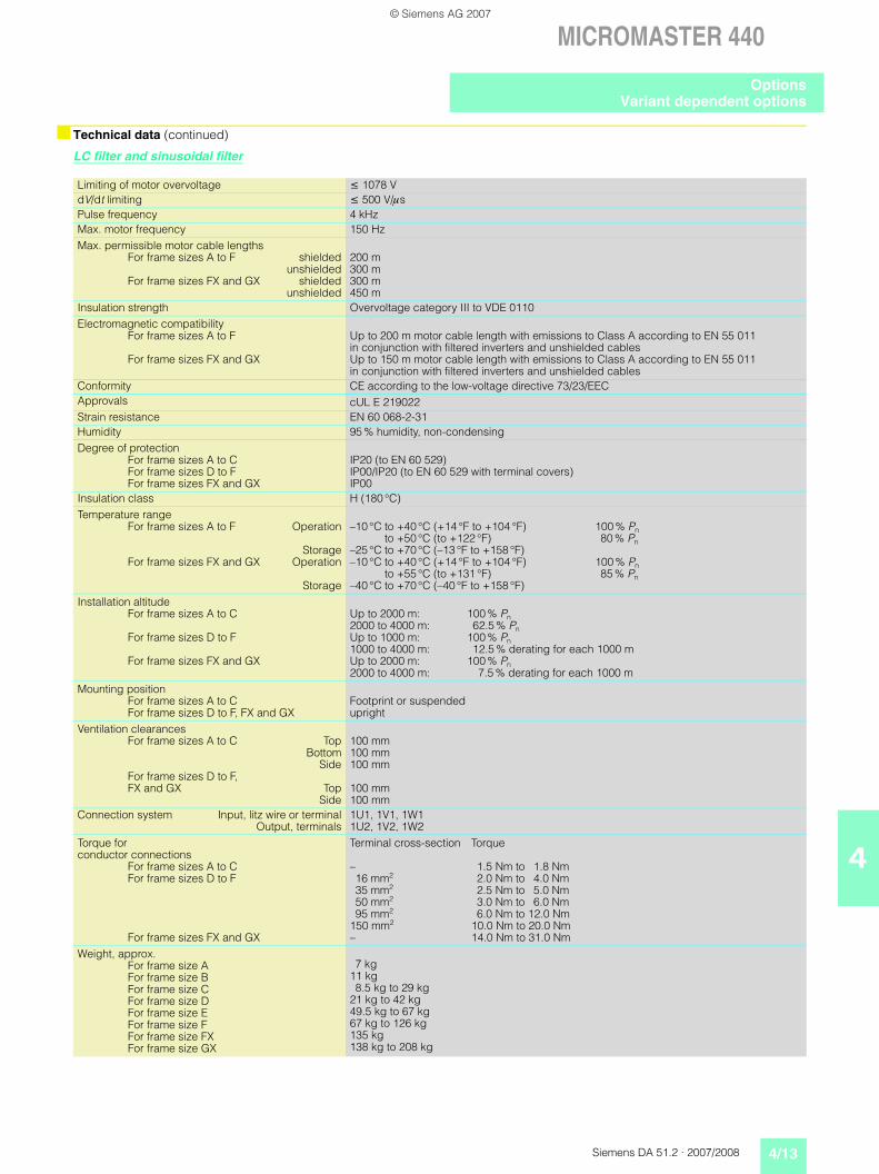
LC filter and sinusoidal filter
Limiting of motor overvoltage 1078 VdV/dt limiting 500 V/sPulse frequency 4 kHzMax. motor frequency 150 HzMax. permissible motor cable lengths
For frame sizes A to F shieldedunshielded
For frame sizes FX and GX shieldedunshielded
200 m300 m300 m450 m
Insulation strength Overvoltage category III to VDE 0110Electromagnetic compatibility
For frame sizes A to F
For frame sizes FX and GX
Up to 200 m motor cable length with emissions to Class A according to EN 55 011 in conjunction with filtered inverters and unshielded cables Up to 150 m motor cable length with emissions to Class A according to EN 55 011 in conjunction with filtered inverters and unshielded cables
Conformity CE according to the low-voltage directive 73/23/EECApprovals cUL E 219022Strain resistance EN 60 068-2-31Humidity 95 % humidity, non-condensingDegree of protection
For frame sizes A to CFor frame sizes D to FFor frame sizes FX and GX
IP20 (to EN 60 529)IP00/IP20 (to EN 60 529 with terminal covers)IP00
Insulation class H (180 °C)Temperature range
For frame sizes A to F Operation
StorageFor frame sizes FX and GX Operation
Storage
–10 °C to +40 °C (+14 °F to +104 °F) 100 % Pnto +50 °C (to +122 °F) 80 % Pn
–25 °C to +70 °C (–13 °F to +158 °F)–10 °C to +40 °C (+14 °F to +104 °F) 100 % Pn
to +55 °C (to +131 °F) 85 % Pn–40 °C to +70 °C (–40 °F to +158 °F)
Installation altitudeFor frame sizes A to C
For frame sizes D to F
For frame sizes FX and GX
Up to 2000 m: 100 % Pn2000 to 4000 m: 62.5 % PnUp to 1000 m: 100 % Pn1000 to 4000 m: 12.5 % derating for each 1000 mUp to 2000 m: 100 % Pn2000 to 4000 m: 7.5 % derating for each 1000 m
Mounting position For frame sizes A to C For frame sizes D to F, FX and GX
Footprint or suspended upright
Ventilation clearances For frame sizes A to C Top
BottomSide
For frame sizes D to F, FX and GX Top
Side
100 mm100 mm100 mm
100 mm100 mm
Connection system Input, litz wire or terminalOutput, terminals
1U1, 1V1, 1W11U2, 1V2, 1W2
Torque for conductor connections
For frame sizes A to CFor frame sizes D to F
For frame sizes FX and GX
Terminal cross-section Torque
– 1.5 Nm to 1.8 Nm16 mm2 2.0 Nm to 4.0 Nm35 mm2 2.5 Nm to 5.0 Nm50 mm2 3.0 Nm to 6.0 Nm95 mm2 6.0 Nm to 12.0 Nm
150 mm2 10.0 Nm to 20.0 Nm– 14.0 Nm to 31.0 Nm
Weight, approx. For frame size AFor frame size BFor frame size CFor frame size DFor frame size EFor frame size FFor frame size FXFor frame size GX
7 kg11 kg8.5 kg to 29 kg
21 kg to 42 kg49.5 kg to 67 kg67 kg to 126 kg135 kg138 kg to 208 kg
OptionsVariant dependent options
© Siemens AG 2007
4/14 Siemens DA 51.2 · 2007/2008
MICROMASTER 440
4
Technical data
Overview
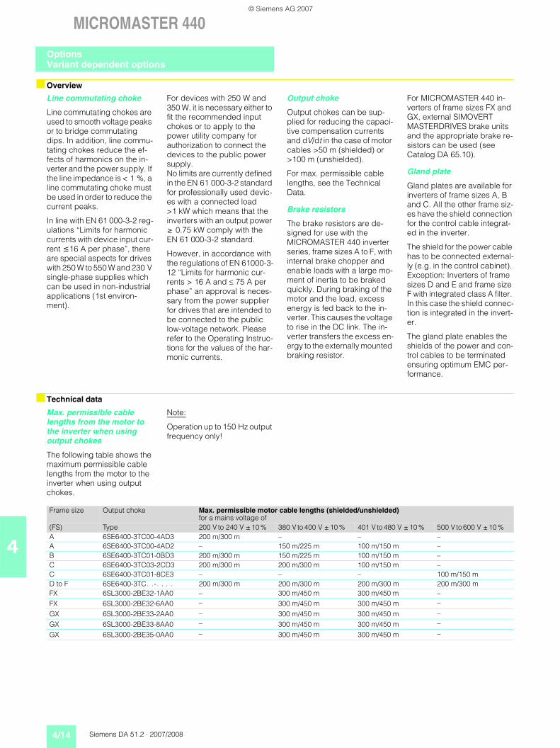
Line commutating choke
Line commutating chokes are used to smooth voltage peaks or to bridge commutating dips. In addition, line commu-tating chokes reduce the ef-fects of harmonics on the in-verter and the power supply. If the line impedance is < 1 %, a line commutating choke must be used in order to reduce the current peaks.
In line with EN 61 000-3-2 reg-ulations “Limits for harmonic currents with device input cur-rent 16 A per phase”, there are special aspects for drives with 250 W to 550 W and 230 V single-phase supplies which can be used in non-industrial applications (1st environ-ment).
For devices with 250 W and 350 W, it is necessary either to fit the recommended input chokes or to apply to the power utility company for authorization to connect the devices to the public power supply. No limits are currently defined in the EN 61 000-3-2 standard for professionally used devic-es with a connected load >1 kW which means that the inverters with an output power 0.75 kW comply with the EN 61 000-3-2 standard.
However, in accordance with the regulations of EN 61000-3-12 “Limits for harmonic cur-rents > 16 A and 75 A per phase” an approval is neces-sary from the power supplier for drives that are intended to be connected to the public low-voltage network. Please refer to the Operating Instruc-tions for the values of the har-monic currents.
Output choke
Output chokes can be sup-plied for reducing the capaci-tive compensation currents and dV/dt in the case of motor cables >50 m (shielded) or >100 m (unshielded).
For max. permissible cable lengths, see the Technical Data.
Brake resistors
The brake resistors are de-signed for use with the MICROMASTER 440 inverter series, frame sizes A to F, with internal brake chopper and enable loads with a large mo-ment of inertia to be braked quickly. During braking of the motor and the load, excess energy is fed back to the in-verter. This causes the voltage to rise in the DC link. The in-verter transfers the excess en-ergy to the externally mounted braking resistor.
For MICROMASTER 440 in-verters of frame sizes FX and GX, external SIMOVERT MASTERDRIVES brake units and the appropriate brake re-sistors can be used (see Catalog DA 65.10).
Gland plate
Gland plates are available for inverters of frame sizes A, B and C. All the other frame siz-es have the shield connection for the control cable integrat-ed in the inverter.
The shield for the power cable has to be connected external-ly (e.g. in the control cabinet). Exception: Inverters of frame sizes D and E and frame size F with integrated class A filter. In this case the shield connec-tion is integrated in the invert-er.
The gland plate enables the shields of the power and con-trol cables to be terminated ensuring optimum EMC per-formance.
Max. permissible cable lengths from the motor to the inverter when using output chokes
The following table shows the maximum permissible cable lengths from the motor to the inverter when using output chokes.
Note:
Operation up to 150 Hz output frequency only!
Frame size Output choke Max. permissible motor cable lengths (shielded/unshielded)for a mains voltage of
(FS) Type 200 V to 240 V ± 10 % 380 V to 400 V ± 10 % 401 V to 480 V ± 10 % 500 V to 600 V ± 10 %A 6SE6400-3TC00-4AD3 200 m/300 m – – –A 6SE6400-3TC00-4AD2 – 150 m/225 m 100 m/150 m –B 6SE6400-3TC01-0BD3 200 m/300 m 150 m/225 m 100 m/150 m –C 6SE6400-3TC03-2CD3 200 m/300 m 200 m/300 m 100 m/150 m –C 6SE6400-3TC01-8CE3 – – – 100 m/150 mD to F 6SE6400-3TC. .-. . . . 200 m/300 m 200 m/300 m 200 m/300 m 200 m/300 mFX 6SL3000-2BE32-1AA0 – 300 m/450 m 300 m/450 m –FX 6SL3000-2BE32-6AA0 – 300 m/450 m 300 m/450 m –
GX 6SL3000-2BE33-2AA0 – 300 m/450 m 300 m/450 m –
GX 6SL3000-2BE33-8AA0 – 300 m/450 m 300 m/450 m –
GX 6SL3000-2BE35-0AA0 – 300 m/450 m 300 m/450 m –
OptionsVariant dependent options
© Siemens AG 2007
Siemens DA 51.2 · 2007/2008 4/15
MICROMASTER 440
4
Design
General installation instructions
Availability of the options as footprint components
Recommended combinations of inverters and options
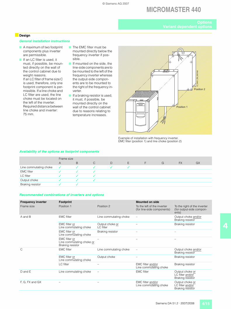
A maximum of two footprint components plus inverter are permissible.
If an LC filter is used, it must, if possible, be moun-ted directly on the wall of the control cabinet due to weight reasons. If an LC filter of frame size C is used, therefore, only one footprint component is per-missible. If a line choke and LC filter are used, the line choke must be located on the left of the inverter. Required distance between line choke and inverter: 75 mm.
The EMC filter must be mounted directly below the frequency inverter if pos-sible.
If mounted on the side, the line-side components are to be mounted to the left of the frequency inverter whereas the output-side compon-ents are to be mounted to the right of the frequency in-verter.
If a braking resistor is used, it must, if possible, be mounted directly on the wall of the control cabinet due to reasons relating to temperature increases.
Frame sizeA B C D E F G FX GX
Line commutating choke
EMC filter
LC filter
Output choke
Braking resistor
Frequency inverter Footprint Mounted on sideFrame size Position 1 Position 2 To the left of the inverter
(for line-side components)To the right of the inverter (for output-side compon-ents)
A and B EMC filter Line commutating choke – Output choke and/or Braking resistor
EMC filter orLine commutating choke
Output choke orLC filter
– Braking resistor
EMC filter orLine commutating choke
Braking resistor – –
EMC filter orLine commutating choke or Braking resistor
– – –
C EMC filter Line commutating choke – Output choke and/or Braking resistor
EMC filter orLine commutating choke
Output choke – Braking resistor
LC filter – EMC filter and/orLine commutating choke
Braking resistor
D and E Line commutating choke – EMC filter Output choke or LC filter and/or Braking resistor
F, G, FX and GX – – EMC filter and/orLine commutating choke
Output choke or LC filter and/or Braking resistor
Example of installation with frequency inverter, EMC filter (position 1) and line choke (position 2)
OptionsVariant dependent options
© Siemens AG 2007
4/16 Siemens DA 51.2 · 2007/2008
MICROMASTER 440
4
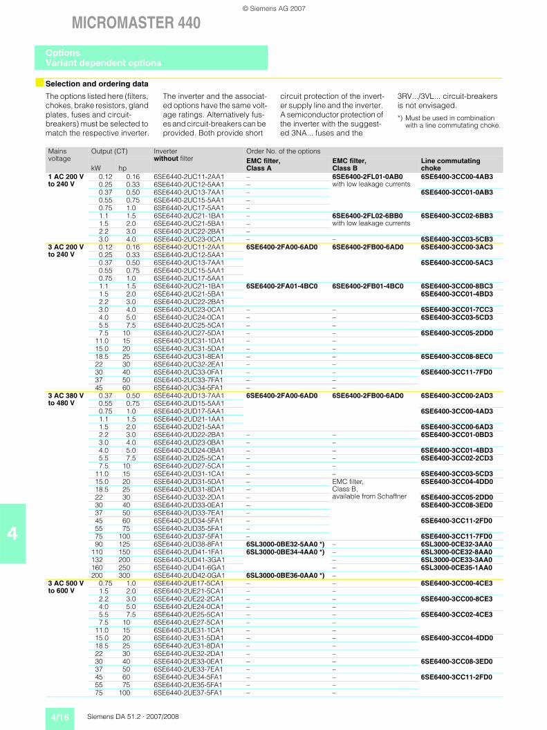
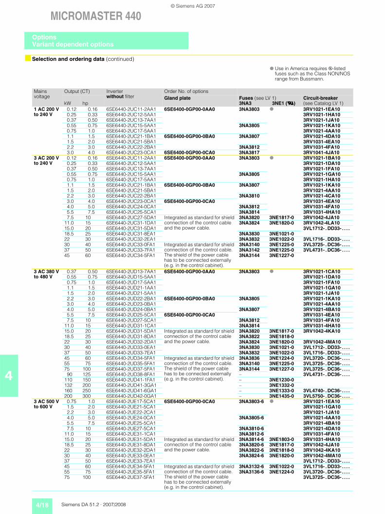
Selection and ordering data
The options listed here (filters, chokes, brake resistors, gland plates, fuses and circuit-breakers) must be selected to match the respective inverter.
The inverter and the associat-ed options have the same volt-age ratings. Alternatively fus-es and circuit-breakers can be provided. Both provide short
circuit protection of the invert-er supply line and the inverter. A semiconductor protection of the inverter with the suggest-ed 3NA... fuses and the
3RV.../3VL... circuit-breakers is not envisaged.
*) Must be used in combination with a line commutating choke.
Mains voltage
Output (CT) Inverterwithout filter
Order No. of the options
kW hpEMC filter, Class A
EMC filter, Class B
Line commutating choke
1 AC 200 V to 240 V
0.12 0.16 6SE6440-2UC11-2AA1 – 6SE6400-2FL01-0AB0with low leakage currents
6SE6400-3CC00-4AB30.25 0.33 6SE6440-2UC12-5AA1 –0.37 0.50 6SE6440-2UC13-7AA1 – 6SE6400-3CC01-0AB30.55 0.75 6SE6440-2UC15-5AA1 –0.75 1.0 6SE6440-2UC17-5AA1 –1.1 1.5 6SE6440-2UC21-1BA1 – 6SE6400-2FL02-6BB0
with low leakage currents6SE6400-3CC02-6BB3
1.5 2.0 6SE6440-2UC21-5BA1 –2.2 3.0 6SE6440-2UC22-2BA1 –3.0 4.0 6SE6440-2UC23-0CA1 – – 6SE6400-3CC03-5CB3
3 AC 200 V to 240 V
0.12 0.16 6SE6440-2UC11-2AA1 6SE6400-2FA00-6AD0 6SE6400-2FB00-6AD0 6SE6400-3CC00-3AC30.25 0.33 6SE6440-2UC12-5AA10.37 0.50 6SE6440-2UC13-7AA1 6SE6400-3CC00-5AC30.55 0.75 6SE6440-2UC15-5AA10.75 1.0 6SE6440-2UC17-5AA11.1 1.5 6SE6440-2UC21-1BA1 6SE6400-2FA01-4BC0 6SE6400-2FB01-4BC0 6SE6400-3CC00-8BC31.5 2.0 6SE6440-2UC21-5BA1 6SE6400-3CC01-4BD32.2 3.0 6SE6440-2UC22-2BA13.0 4.0 6SE6440-2UC23-0CA1 – – 6SE6400-3CC01-7CC34.0 5.0 6SE6440-2UC24-0CA1 – – 6SE6400-3CC03-5CD35.5 7.5 6SE6440-2UC25-5CA1 – –7.5 10 6SE6440-2UC27-5DA1 – – 6SE6400-3CC05-2DD0
11.0 15 6SE6440-2UC31-1DA1 – –15.0 20 6SE6440-2UC31-5DA1 – –18.5 25 6SE6440-2UC31-8EA1 – – 6SE6400-3CC08-8EC022 30 6SE6440-2UC32-2EA1 – –30 40 6SE6440-2UC33-0FA1 – – 6SE6400-3CC11-7FD037 50 6SE6440-2UC33-7FA1 – –45 60 6SE6440-2UC34-5FA1 – –
3 AC 380 V to 480 V
0.37 0.50 6SE6440-2UD13-7AA1 6SE6400-2FA00-6AD0 6SE6400-2FB00-6AD0 6SE6400-3CC00-2AD30.55 0.75 6SE6440-2UD15-5AA10.75 1.0 6SE6440-2UD17-5AA1 6SE6400-3CC00-4AD31.1 1.5 6SE6440-2UD21-1AA11.5 2.0 6SE6440-2UD21-5AA1 6SE6400-3CC00-6AD32.2 3.0 6SE6440-2UD22-2BA1 – – 6SE6400-3CC01-0BD33.0 4.0 6SE6440-2UD23-0BA1 – –4.0 5.0 6SE6440-2UD24-0BA1 – – 6SE6400-3CC01-4BD35.5 7.5 6SE6440-2UD25-5CA1 – – 6SE6400-3CC02-2CD37.5 10 6SE6440-2UD27-5CA1 – –
11.0 15 6SE6440-2UD31-1CA1 – – 6SE6400-3CC03-5CD315.0 20 6SE6440-2UD31-5DA1 – EMC filter,
Class B, available from Schaffner
6SE6400-3CC04-4DD018.5 25 6SE6440-2UD31-8DA1 –22 30 6SE6440-2UD32-2DA1 – 6SE6400-3CC05-2DD030 40 6SE6440-2UD33-0EA1 – 6SE6400-3CC08-3ED037 50 6SE6440-2UD33-7EA1 –45 60 6SE6440-2UD34-5FA1 – 6SE6400-3CC11-2FD055 75 6SE6440-2UD35-5FA1 –75 100 6SE6440-2UD37-5FA1 – 6SE6400-3CC11-7FD090 125 6SE6440-2UD38-8FA1 6SL3000-0BE32-5AA0 *) – 6SL3000-0CE32-3AA0
110 150 6SE6440-2UD41-1FA1 6SL3000-0BE34-4AA0 *) – 6SL3000-0CE32-8AA0132 200 6SE6440-2UD41-3GA1 – 6SL3000-0CE33-3AA0160 250 6SE6440-2UD41-6GA1 – 6SL3000-0CE35-1AA0200 300 6SE6440-2UD42-0GA1 6SL3000-0BE36-0AA0 *) –
3 AC 500 V to 600 V
0.75 1.0 6SE6440-2UE17-5CA1 – – 6SE6400-3CC00-4CE31.5 2.0 6SE6440-2UE21-5CA1 – –2.2 3.0 6SE6440-2UE22-2CA1 – – 6SE6400-3CC00-8CE34.0 5.0 6SE6440-2UE24-0CA1 – –5.5 7.5 6SE6440-2UE25-5CA1 – – 6SE6400-3CC02-4CE37.5 10 6SE6440-2UE27-5CA1 – –
11.0 15 6SE6440-2UE31-1CA1 – –15.0 20 6SE6440-2UE31-5DA1 – – 6SE6400-3CC04-4DD018.5 25 6SE6440-2UE31-8DA1 – –22 30 6SE6440-2UE32-2DA1 – –30 40 6SE6440-2UE33-0EA1 – – 6SE6400-3CC08-3ED037 50 6SE6440-2UE33-7EA1 – –45 60 6SE6440-2UE34-5FA1 – – 6SE6400-3CC11-2FD055 75 6SE6440-2UE35-5FA1 – –75 100 6SE6440-2UE37-5FA1 – –
OptionsVariant dependent options
© Siemens AG 2007
Siemens DA 51.2 · 2007/2008 4/17
MICROMASTER 440
4
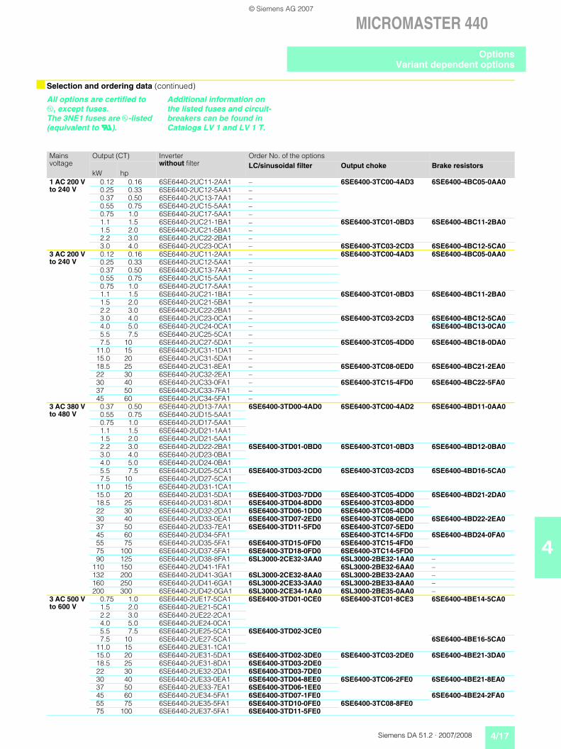
Selection and ordering data (continued)
All options are certified to u, except fuses. The 3NE1 fuses are u-listed (equivalent to U).
Additional information on the listed fuses and circuit-breakers can be found in Catalogs LV 1 and LV 1 T.
Mains voltage
Output (CT) Inverterwithout filter
Order No. of the options
kW hpLC/sinusoidal filter Output choke Brake resistors
1 AC 200 V to 240 V
0.12 0.16 6SE6440-2UC11-2AA1 – 6SE6400-3TC00-4AD3 6SE6400-4BC05-0AA00.25 0.33 6SE6440-2UC12-5AA1 –0.37 0.50 6SE6440-2UC13-7AA1 –0.55 0.75 6SE6440-2UC15-5AA1 –0.75 1.0 6SE6440-2UC17-5AA1 –1.1 1.5 6SE6440-2UC21-1BA1 – 6SE6400-3TC01-0BD3 6SE6400-4BC11-2BA01.5 2.0 6SE6440-2UC21-5BA1 –2.2 3.0 6SE6440-2UC22-2BA1 –3.0 4.0 6SE6440-2UC23-0CA1 – 6SE6400-3TC03-2CD3 6SE6400-4BC12-5CA0
3 AC 200 V to 240 V
0.12 0.16 6SE6440-2UC11-2AA1 – 6SE6400-3TC00-4AD3 6SE6400-4BC05-0AA00.25 0.33 6SE6440-2UC12-5AA1 –0.37 0.50 6SE6440-2UC13-7AA1 –0.55 0.75 6SE6440-2UC15-5AA1 –0.75 1.0 6SE6440-2UC17-5AA1 –1.1 1.5 6SE6440-2UC21-1BA1 – 6SE6400-3TC01-0BD3 6SE6400-4BC11-2BA01.5 2.0 6SE6440-2UC21-5BA1 –2.2 3.0 6SE6440-2UC22-2BA1 –3.0 4.0 6SE6440-2UC23-0CA1 – 6SE6400-3TC03-2CD3 6SE6400-4BC12-5CA04.0 5.0 6SE6440-2UC24-0CA1 – 6SE6400-4BC13-0CA05.5 7.5 6SE6440-2UC25-5CA1 –7.5 10 6SE6440-2UC27-5DA1 – 6SE6400-3TC05-4DD0 6SE6400-4BC18-0DA0
11.0 15 6SE6440-2UC31-1DA1 –15.0 20 6SE6440-2UC31-5DA1 –18.5 25 6SE6440-2UC31-8EA1 – 6SE6400-3TC08-0ED0 6SE6400-4BC21-2EA022 30 6SE6440-2UC32-2EA1 –30 40 6SE6440-2UC33-0FA1 – 6SE6400-3TC15-4FD0 6SE6400-4BC22-5FA037 50 6SE6440-2UC33-7FA1 –45 60 6SE6440-2UC34-5FA1 –
3 AC 380 V to 480 V
0.37 0.50 6SE6440-2UD13-7AA1 6SE6400-3TD00-4AD0 6SE6400-3TC00-4AD2 6SE6400-4BD11-0AA00.55 0.75 6SE6440-2UD15-5AA10.75 1.0 6SE6440-2UD17-5AA11.1 1.5 6SE6440-2UD21-1AA11.5 2.0 6SE6440-2UD21-5AA12.2 3.0 6SE6440-2UD22-2BA1 6SE6400-3TD01-0BD0 6SE6400-3TC01-0BD3 6SE6400-4BD12-0BA03.0 4.0 6SE6440-2UD23-0BA14.0 5.0 6SE6440-2UD24-0BA15.5 7.5 6SE6440-2UD25-5CA1 6SE6400-3TD03-2CD0 6SE6400-3TC03-2CD3 6SE6400-4BD16-5CA07.5 10 6SE6440-2UD27-5CA1
11.0 15 6SE6440-2UD31-1CA115.0 20 6SE6440-2UD31-5DA1 6SE6400-3TD03-7DD0 6SE6400-3TC05-4DD0 6SE6400-4BD21-2DA018.5 25 6SE6440-2UD31-8DA1 6SE6400-3TD04-8DD0 6SE6400-3TC03-8DD022 30 6SE6440-2UD32-2DA1 6SE6400-3TD06-1DD0 6SE6400-3TC05-4DD030 40 6SE6440-2UD33-0EA1 6SE6400-3TD07-2ED0 6SE6400-3TC08-0ED0 6SE6400-4BD22-2EA037 50 6SE6440-2UD33-7EA1 6SE6400-3TD11-5FD0 6SE6400-3TC07-5ED045 60 6SE6440-2UD34-5FA1 6SE6400-3TC14-5FD0 6SE6400-4BD24-0FA055 75 6SE6440-2UD35-5FA1 6SE6400-3TD15-0FD0 6SE6400-3TC15-4FD075 100 6SE6440-2UD37-5FA1 6SE6400-3TD18-0FD0 6SE6400-3TC14-5FD090 125 6SE6440-2UD38-8FA1 6SL3000-2CE32-3AA0 6SL3000-2BE32-1AA0 –
110 150 6SE6440-2UD41-1FA1 6SL3000-2BE32-6AA0 –132 200 6SE6440-2UD41-3GA1 6SL3000-2CE32-8AA0 6SL3000-2BE33-2AA0 –160 250 6SE6440-2UD41-6GA1 6SL3000-2CE33-3AA0 6SL3000-2BE33-8AA0 –200 300 6SE6440-2UD42-0GA1 6SL3000-2CE34-1AA0 6SL3000-2BE35-0AA0 –
3 AC 500 V to 600 V
0.75 1.0 6SE6440-2UE17-5CA1 6SE6400-3TD01-0CE0 6SE6400-3TC01-8CE3 6SE6400-4BE14-5CA01.5 2.0 6SE6440-2UE21-5CA12.2 3.0 6SE6440-2UE22-2CA14.0 5.0 6SE6440-2UE24-0CA15.5 7.5 6SE6440-2UE25-5CA1 6SE6400-3TD02-3CE07.5 10 6SE6440-2UE27-5CA1 6SE6400-4BE16-5CA0
11.0 15 6SE6440-2UE31-1CA115.0 20 6SE6440-2UE31-5DA1 6SE6400-3TD02-3DE0 6SE6400-3TC03-2DE0 6SE6400-4BE21-3DA018.5 25 6SE6440-2UE31-8DA1 6SE6400-3TD03-2DE022 30 6SE6440-2UE32-2DA1 6SE6400-3TD03-7DE030 40 6SE6440-2UE33-0EA1 6SE6400-3TD04-8EE0 6SE6400-3TC06-2FE0 6SE6400-4BE21-8EA037 50 6SE6440-2UE33-7EA1 6SE6400-3TD06-1EE045 60 6SE6440-2UE34-5FA1 6SE6400-3TD07-1FE0 6SE6400-4BE24-2FA055 75 6SE6440-2UE35-5FA1 6SE6400-3TD10-0FE0 6SE6400-3TC08-8FE075 100 6SE6440-2UE37-5FA1 6SE6400-3TD11-5FE0
OptionsVariant dependent options
© Siemens AG 2007
4/18 Siemens DA 51.2 · 2007/2008
MICROMASTER 440
4
Selection and ordering data (continued)
Mains voltage
Output (CT) Inverterwithout filter
Order No. of options
kW hpGland plate Fuses (see LV 1)
3NA3 3NE1 (U)Circuit-breaker(see Catalog LV 1)
1 AC 200 V to 240 V
0.12 0.16 6SE6440-2UC11-2AA1 6SE6400-0GP00-0AA0 3NA3803 3RV1021-1EA100.25 0.33 6SE6440-2UC12-5AA1 3RV1021-1HA100.37 0.50 6SE6440-2UC13-7AA1 3RV1021-1JA100.55 0.75 6SE6440-2UC15-5AA1 3NA3805 3RV1021-1KA100.75 1.0 6SE6440-2UC17-5AA1 3RV1021-4AA101.1 1.5 6SE6440-2UC21-1BA1 6SE6400-0GP00-0BA0 3NA3807 3RV1021-4DA101.5 2.0 6SE6440-2UC21-5BA1 3RV1031-4EA102.2 3.0 6SE6440-2UC22-2BA1 3NA3812 3RV1031-4FA103.0 4.0 6SE6440-2UC23-0CA1 6SE6400-0GP00-0CA0 3NA3817 3RV1041-4JA10
3 AC 200 V to 240 V
0.12 0.16 6SE6440-2UC11-2AA1 6SE6400-0GP00-0AA0 3NA3803 3RV1021-1BA100.25 0.33 6SE6440-2UC12-5AA1 3RV1021-1DA100.37 0.50 6SE6440-2UC13-7AA1 3RV1021-1FA100.55 0.75 6SE6440-2UC15-5AA1 3NA3805 3RV1021-1GA100.75 1.0 6SE6440-2UC17-5AA1 3RV1021-1HA101.1 1.5 6SE6440-2UC21-1BA1 6SE6400-0GP00-0BA0 3NA3807 3RV1021-1KA101.5 2.0 6SE6440-2UC21-5BA1 3RV1021-4AA102.2 3.0 6SE6440-2UC22-2BA1 3NA3810 3RV1021-4CA103.0 4.0 6SE6440-2UC23-0CA1 6SE6400-0GP00-0CA0 3RV1031-4EA104.0 5.0 6SE6440-2UC24-0CA1 3NA3812 3RV1031-4FA105.5 7.5 6SE6440-2UC25-5CA1 3NA3814 3RV1031-4HA107.5 10 6SE6440-2UC27-5DA1 Integrated as standard for shield
connection of the control cable and the power cable.
3NA3820 3NE1817-0 3RV1042-4JA1011.0 15 6SE6440-2UC31-1DA1 3NA3824 3NE1820-0 3RV1042-4LA1015.0 20 6SE6440-2UC31-5DA1 3VL1712- . DD33- . . . .
18.5 25 6SE6440-2UC31-8EA1 3NA3830 3NE1021-022 30 6SE6440-2UC32-2EA1 3NA3832 3NE1022-0 3VL1716- . DD33- . . . .
30 40 6SE6440-2UC33-0FA1 Integrated as standard for shield connection of the control cable. The shield of the power cable has to be connected externally (e.g. in the control cabinet).
3NA3140 3NE1225-0 3VL3725- . DC36- . . . .
37 50 6SE6440-2UC33-7FA1 3NA3142 3NE1225-0 3VL4731- . DC36- . . . .
45 60 6SE6440-2UC34-5FA1 3NA3144 3NE1227-0
3 AC 380 V to 480 V
0.37 0.50 6SE6440-2UD13-7AA1 6SE6400-0GP00-0AA0 3NA3803 3RV1021-1CA100.55 0.75 6SE6440-2UD15-5AA1 3RV1021-1DA100.75 1.0 6SE6440-2UD17-5AA1 3RV1021-1FA101.1 1.5 6SE6440-2UD21-1AA1 3RV1021-1GA101.5 2.0 6SE6440-2UD21-5AA1 3RV1021-1JA102.2 3.0 6SE6440-2UD22-2BA1 6SE6400-0GP00-0BA0 3NA3805 3RV1021-1KA103.0 4.0 6SE6440-2UD23-0BA1 3RV1021-4AA104.0 5.0 6SE6440-2UD24-0BA1 3NA3807 3RV1021-4BA105.5 7.5 6SE6440-2UD25-5CA1 6SE6400-0GP00-0CA0 3RV1031-4EA107.5 10 6SE6440-2UD27-5CA1 3NA3812 3RV1031-4FA10
11.0 15 6SE6440-2UD31-1CA1 3NA3814 3RV1031-4HA1015.0 20 6SE6440-2UD31-5DA1 Integrated as standard for shield
connection of the control cable and the power cable.
3NA3820 3NE1817-0 3RV1042-4KA1018.5 25 6SE6440-2UD31-8DA1 3NA3822 3NE1818-022 30 6SE6440-2UD32-2DA1 3NA3824 3NE1820-0 3RV1042-4MA1030 40 6SE6440-2UD33-0EA1 3NA3830 3NE1021-0 3VL1712- . DD33- . . . .
37 50 6SE6440-2UD33-7EA1 3NA3832 3NE1022-0 3VL1716- . DD33- . . . .
45 60 6SE6440-2UD34-5FA1 Integrated as standard for shield connection of the control cable. The shield of the power cable has to be connected externally (e.g. in the control cabinet).
3NA3836 3NE1224-0 3VL3720- . DC36- . . . .
55 75 6SE6440-2UD35-5FA1 3NA3140 3NE1225-0 3VL3725- . DC36- . . . .
75 100 6SE6440-2UD37-5FA1 3NA3144 3NE1227-0 3VL3725- . DC36- . . . .
90 125 6SE6440-2UD38-8FA1 – 3VL4731- . DC36- . . . .110 150 6SE6440-2UD41-1FA1 – 3NE1230-0132 200 6SE6440-2UD41-3GA1 – 3NE1332-0160 250 6SE6440-2UD41-6GA1 – 3NE1333-0 3VL4740- . DC36- . . . .
200 300 6SE6440-2UD42-0GA1 – 3NE1435-0 3VL5750- . DC36- . . . .
3 AC 500 V to 600 V
0.75 1.0 6SE6440-2UE17-5CA1 6SE6400-0GP00-0CA0 3NA3803-6 3RV1021-1EA101.5 2.0 6SE6440-2UE21-5CA1 3RV1021-1GA102.2 3.0 6SE6440-2UE22-2CA1 3RV1021-1JA104.0 5.0 6SE6440-2UE24-0CA1 3NA3805-6 3RV1021-4AA105.5 7.5 6SE6440-2UE25-5CA1 3RV1021-4BA107.5 10 6SE6440-2UE27-5CA1 3NA3810-6 3RV1021-4DA10
11.0 15 6SE6440-2UE31-1CA1 3NA3812-6 3RV1031-4FA1015.0 20 6SE6440-2UE31-5DA1 Integrated as standard for shield
connection of the control cable and the power cable.
3NA3814-6 3NE1803-0 3RV1031-4HA1018.5 25 6SE6440-2UE31-8DA1 3NA3820-6 3NE1817-0 3RV1042-4JA1022 30 6SE6440-2UE32-2DA1 3NA3822-6 3NE1818-0 3RV1042-4KA1030 40 6SE6440-2UE33-0EA1 3NA3824-6 3NE1820-0 3RV1042-4MA1037 50 6SE6440-2UE33-7EA1 3VL1712- . DD33- . . . .
45 60 6SE6440-2UE34-5FA1 Integrated as standard for shield connection of the control cable. The shield of the power cable has to be connected externally (e.g. in the control cabinet).
3NA3132-6 3NE1022-0 3VL1716- . DD33- . . . .
55 75 6SE6440-2UE35-5FA1 3NA3136-6 3NE1224-0 3VL3720- . DC36- . . . .
75 100 6SE6440-2UE37-5FA1 3VL3725- . DC36- . . . .
Use in America requires u-listed fuses such as the Class NON/NOS range from Bussmann.
OptionsVariant dependent options
© Siemens AG 2007
Siemens DA 51.2 · 2007/2008 4/19
MICROMASTER 440
4
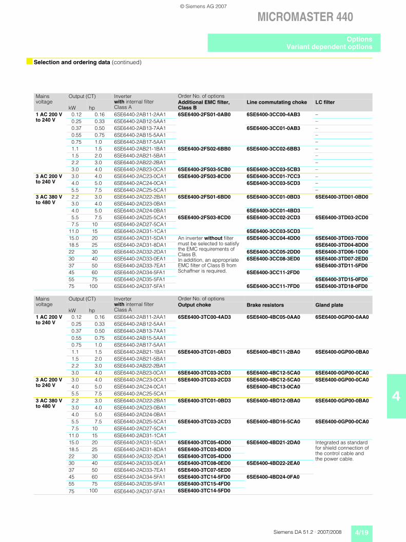
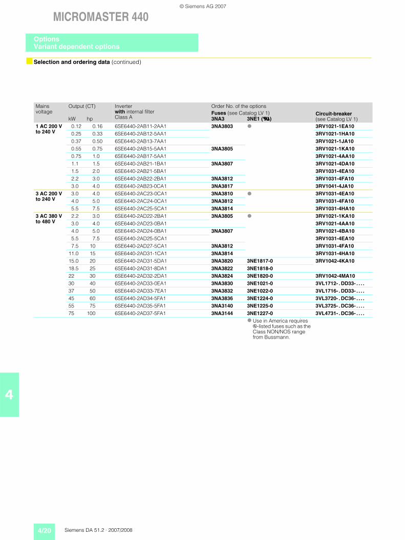
Selection and ordering data (continued)
Mains voltage
Output (CT) Inverter with internal filter Class A
Order No. of options
kW hpAdditional EMC filter,Class B
Line commutating choke LC filter
1 AC 200 V to 240 V
0.12 0.16 6SE6440-2AB11-2AA1 6SE6400-2FS01-0AB0 6SE6400-3CC00-4AB3 –0.25 0.33 6SE6440-2AB12-5AA1 –0.37 0.50 6SE6440-2AB13-7AA1 6SE6400-3CC01-0AB3 –0.55 0.75 6SE6440-2AB15-5AA1 –0.75 1.0 6SE6440-2AB17-5AA1 –1.1 1.5 6SE6440-2AB21-1BA1 6SE6400-2FS02-6BB0 6SE6400-3CC02-6BB3 –1.5 2.0 6SE6440-2AB21-5BA1 –2.2 3.0 6SE6440-2AB22-2BA1 –3.0 4.0 6SE6440-2AB23-0CA1 6SE6400-2FS03-5CB0 6SE6400-3CC03-5CB3 –
3 AC 200 V to 240 V
3.0 4.0 6SE6440-2AC23-0CA1 6SE6400-2FS03-8CD0 6SE6400-3CC01-7CC3 –4.0 5.0 6SE6440-2AC24-0CA1 6SE6400-3CC03-5CD3 –5.5 7.5 6SE6440-2AC25-5CA1 –
3 AC 380 V to 480 V
2.2 3.0 6SE6440-2AD22-2BA1 6SE6400-2FS01-6BD0 6SE6400-3CC01-0BD3 6SE6400-3TD01-0BD03.0 4.0 6SE6440-2AD23-0BA14.0 5.0 6SE6440-2AD24-0BA1 6SE6400-3CC01-4BD35.5 7.5 6SE6440-2AD25-5CA1 6SE6400-2FS03-8CD0 6SE6400-3CC02-2CD3 6SE6400-3TD03-2CD07.5 10 6SE6440-2AD27-5CA1
11.0 15 6SE6440-2AD31-1CA1 6SE6400-3CC03-5CD315.0 20 6SE6440-2AD31-5DA1 An inverter without filter
must be selected to satisfy the EMC requirements of Class B. In addition, an appropriate EMC filter of Class B from Schaffner is required.
6SE6400-3CC04-4DD0 6SE6400-3TD03-7DD018.5 25 6SE6440-2AD31-8DA1 6SE6400-3TD04-8DD022 30 6SE6440-2AD32-2DA1 6SE6400-3CC05-2DD0 6SE6400-3TD06-1DD030 40 6SE6440-2AD33-0EA1 6SE6400-3CC08-3ED0 6SE6400-3TD07-2ED037 50 6SE6440-2AD33-7EA1 6SE6400-3TD11-5FD045 60 6SE6440-2AD34-5FA1 6SE6400-3CC11-2FD055 75 6SE6440-2AD35-5FA1 6SE6400-3TD15-0FD075 100 6SE6440-2AD37-5FA1 6SE6400-3CC11-7FD0 6SE6400-3TD18-0FD0
Mains voltage
Output (CT) Inverter with internal filter Class A
Order No. of options
kW hpOutput choke Brake resistors Gland plate
1 AC 200 V to 240 V
0.12 0.16 6SE6440-2AB11-2AA1 6SE6400-3TC00-4AD3 6SE6400-4BC05-0AA0 6SE6400-0GP00-0AA00.25 0.33 6SE6440-2AB12-5AA10.37 0.50 6SE6440-2AB13-7AA10.55 0.75 6SE6440-2AB15-5AA10.75 1.0 6SE6440-2AB17-5AA11.1 1.5 6SE6440-2AB21-1BA1 6SE6400-3TC01-0BD3 6SE6400-4BC11-2BA0 6SE6400-0GP00-0BA01.5 2.0 6SE6440-2AB21-5BA12.2 3.0 6SE6440-2AB22-2BA13.0 4.0 6SE6440-2AB23-0CA1 6SE6400-3TC03-2CD3 6SE6400-4BC12-5CA0 6SE6400-0GP00-0CA0
3 AC 200 V to 240 V
3.0 4.0 6SE6440-2AC23-0CA1 6SE6400-3TC03-2CD3 6SE6400-4BC12-5CA0 6SE6400-0GP00-0CA04.0 5.0 6SE6440-2AC24-0CA1 6SE6400-4BC13-0CA05.5 7.5 6SE6440-2AC25-5CA1
3 AC 380 V to 480 V
2.2 3.0 6SE6440-2AD22-2BA1 6SE6400-3TC01-0BD3 6SE6400-4BD12-0BA0 6SE6400-0GP00-0BA03.0 4.0 6SE6440-2AD23-0BA14.0 5.0 6SE6440-2AD24-0BA15.5 7.5 6SE6440-2AD25-5CA1 6SE6400-3TC03-2CD3 6SE6400-4BD16-5CA0 6SE6400-0GP00-0CA07.5 10 6SE6440-2AD27-5CA1
11.0 15 6SE6440-2AD31-1CA115.0 20 6SE6440-2AD31-5DA1 6SE6400-3TC05-4DD0 6SE6400-4BD21-2DA0 Integrated as standard
for shield connection of the control cable and the power cable.
18.5 25 6SE6440-2AD31-8DA1 6SE6400-3TC03-8DD022 30 6SE6440-2AD32-2DA1 6SE6400-3TC05-4DD030 40 6SE6440-2AD33-0EA1 6SE6400-3TC08-0ED0 6SE6400-4BD22-2EA037 50 6SE6440-2AD33-7EA1 6SE6400-3TC07-5ED045 60 6SE6440-2AD34-5FA1 6SE6400-3TC14-5FD0 6SE6400-4BD24-0FA055 75 6SE6440-2AD35-5FA1 6SE6400-3TC15-4FD075 100 6SE6440-2AD37-5FA1 6SE6400-3TC14-5FD0
OptionsVariant dependent options
© Siemens AG 2007
4/20 Siemens DA 51.2 · 2007/2008
MICROMASTER 440
4
Selection and ordering data (continued)
Mains voltage
Output (CT) Inverter with internal filter Class A
Order No. of the optionsFuses (see Catalog LV 1) Circuit-breaker
(see Catalog LV 1)kW hp 3NA3 3NE1 (U)1 AC 200 V to 240 V
0.12 0.16 6SE6440-2AB11-2AA1 3NA3803 3RV1021-1EA100.25 0.33 6SE6440-2AB12-5AA1 3RV1021-1HA100.37 0.50 6SE6440-2AB13-7AA1 3RV1021-1JA100.55 0.75 6SE6440-2AB15-5AA1 3NA3805 3RV1021-1KA100.75 1.0 6SE6440-2AB17-5AA1 3RV1021-4AA101.1 1.5 6SE6440-2AB21-1BA1 3NA3807 3RV1021-4DA101.5 2.0 6SE6440-2AB21-5BA1 3RV1031-4EA102.2 3.0 6SE6440-2AB22-2BA1 3NA3812 3RV1031-4FA103.0 4.0 6SE6440-2AB23-0CA1 3NA3817 3RV1041-4JA10
3 AC 200 V to 240 V
3.0 4.0 6SE6440-2AC23-0CA1 3NA3810 3RV1031-4EA104.0 5.0 6SE6440-2AC24-0CA1 3NA3812 3RV1031-4FA105.5 7.5 6SE6440-2AC25-5CA1 3NA3814 3RV1031-4HA10
3 AC 380 V to 480 V
2.2 3.0 6SE6440-2AD22-2BA1 3NA3805 3RV1021-1KA103.0 4.0 6SE6440-2AD23-0BA1 3RV1021-4AA104.0 5.0 6SE6440-2AD24-0BA1 3NA3807 3RV1021-4BA105.5 7.5 6SE6440-2AD25-5CA1 3RV1031-4EA107.5 10 6SE6440-2AD27-5CA1 3NA3812 3RV1031-4FA10
11.0 15 6SE6440-2AD31-1CA1 3NA3814 3RV1031-4HA1015.0 20 6SE6440-2AD31-5DA1 3NA3820 3NE1817-0 3RV1042-4KA1018.5 25 6SE6440-2AD31-8DA1 3NA3822 3NE1818-022 30 6SE6440-2AD32-2DA1 3NA3824 3NE1820-0 3RV1042-4MA1030 40 6SE6440-2AD33-0EA1 3NA3830 3NE1021-0 3VL1712- . DD33- . . . .
37 50 6SE6440-2AD33-7EA1 3NA3832 3NE1022-0 3VL1716- . DD33- . . . .
45 60 6SE6440-2AD34-5FA1 3NA3836 3NE1224-0 3VL3720- . DC36- . . . .
55 75 6SE6440-2AD35-5FA1 3NA3140 3NE1225-0 3VL3725- . DC36- . . . .
75 100 6SE6440-2AD37-5FA1 3NA3144 3NE1227-0 3VL4731- . DC36- . . . .
Use in America requires u-listed fuses such as the Class NON/NOS range from Bussmann.
OptionsVariant dependent options
© Siemens AG 2007
Siemens DA 51.2 · 2007/2008 4/21
MICROMASTER 440
4
Overview
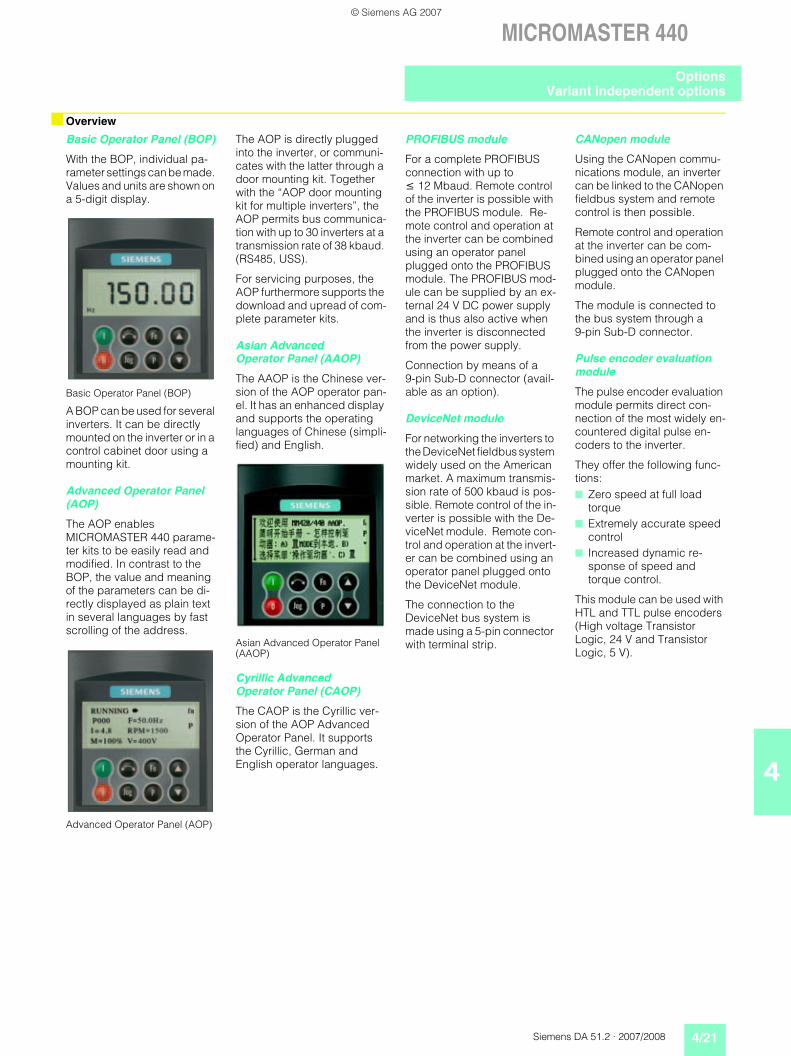
Basic Operator Panel (BOP)
With the BOP, individual pa-rameter settings can be made. Values and units are shown on a 5-digit display.
Basic Operator Panel (BOP)
A BOP can be used for several inverters. It can be directly mounted on the inverter or in a control cabinet door using a mounting kit.
Advanced Operator Panel (AOP)
The AOP enables MICROMASTER 440 parame-ter kits to be easily read and modified. In contrast to the BOP, the value and meaning of the parameters can be di-rectly displayed as plain text in several languages by fast scrolling of the address.
Advanced Operator Panel (AOP)
The AOP is directly plugged into the inverter, or communi-cates with the latter through a door mounting kit. Together with the “AOP door mounting kit for multiple inverters”, the AOP permits bus communica-tion with up to 30 inverters at a transmission rate of 38 kbaud. (RS485, USS).
For servicing purposes, the AOP furthermore supports the download and upread of com-plete parameter kits.
Asian AdvancedOperator Panel (AAOP)
The AAOP is the Chinese ver-sion of the AOP operator pan-el. It has an enhanced display and supports the operating languages of Chinese (simpli-fied) and English.
Asian Advanced Operator Panel (AAOP)
Cyrillic Advanced Operator Panel (CAOP)
The CAOP is the Cyrillic ver-sion of the AOP Advanced Operator Panel. It supports the Cyrillic, German and English operator languages.
PROFIBUS module
For a complete PROFIBUS connection with up to 12 Mbaud. Remote control of the inverter is possible with the PROFIBUS module. Re-mote control and operation at the inverter can be combined using an operator panel plugged onto the PROFIBUS module. The PROFIBUS mod-ule can be supplied by an ex-ternal 24 V DC power supply and is thus also active when the inverter is disconnected from the power supply.
Connection by means of a 9-pin Sub-D connector (avail-able as an option).
DeviceNet module
For networking the inverters to the DeviceNet fieldbus system widely used on the American market. A maximum transmis-sion rate of 500 kbaud is pos-sible. Remote control of the in-verter is possible with the De-viceNet module. Remote con-trol and operation at the invert-er can be combined using an operator panel plugged onto the DeviceNet module.
The connection to the DeviceNet bus system is made using a 5-pin connector with terminal strip.
CANopen module
Using the CANopen commu-nications module, an inverter can be linked to the CANopen fieldbus system and remote control is then possible.
Remote control and operation at the inverter can be com-bined using an operator panel plugged onto the CANopen module.
The module is connected to the bus system through a 9-pin Sub-D connector.
Pulse encoder evaluation module
The pulse encoder evaluation module permits direct con-nection of the most widely en-countered digital pulse en-coders to the inverter.
They offer the following func-tions: Zero speed at full load
torque Extremely accurate speed
control Increased dynamic re-
sponse of speed and torque control.
This module can be used with HTL and TTL pulse encoders (High voltage Transistor Logic, 24 V and Transistor Logic, 5 V).
OptionsVariant independent options
© Siemens AG 2007
4/22 Siemens DA 51.2 · 2007/2008
MICROMASTER 440
4
Overview (continued)
Selection and ordering data
The options listed here are suitable for all MICROMASTER 440 inverters.
Connection kit forPC to inverter
For controlling an inverter di-rectly from a PC if the appro-priate software has been in-stalled (e.g. STARTER). Isolat-ed RS-232 adapter module for reliable point-to-point connec-tion to a PC. Includes a Sub-D connector and an RS-232 standard cable (3 m).
Connection kit for PC to AOP
For connecting a PC to an AOP or AAOP. Offline pro-gramming of inverters and archiving of parameter kits possible. Includes a desktop attachment kit for an AOP or AAOP, an RS-232 standard cable (3 m) with Sub-D con-nectors and a universal power supply unit.
Operator panel door mount-ing kit for single inverter
For mounting an operator panel in a control cabinet door. Degree of protection IP56. Contains a cable adapter module with screw-less terminals for use with user's own RS-232 cables 1).
AOP door mounting kit for multiple inverters (USS)
For mounting an AOP or AAOP in a control cabinet door. Degree of protection IP56. The AOP or AAOP can com-municate with several invert-ers by means of the RS-485 USS protocol. The 4-pin con-necting cable from the AOP or AAOP to the RS-485 terminals of the inverter and to the 24 V user terminal strip is not in-cluded 2).
Start-up tools
• STARTERStarter is graphic start-up software for guided start-up for MICROMASTER 410/420/430/440 frequency in-verters under Windows 2000/XP Professional. Pa-rameter lists can be read out, altered, stored, entered and printed.
• DriveMonitoris a start-up software for list-oriented programming of frequency inverters. This program executes under Windows 98/NT/2000/ME/XP Professional.
Both programs are included on the Docu DVD which is pro-vided with every inverter.
Options Order No.Basic Operator Panel (BOP) 6SE6400-0BP00-0AA0Advanced Operator Panel (AOP) 6SE6400-0AP00-0AA1Asian Advanced Operator Panel (AAOP) 6SE6400-0AP00-0AB0Cyrillic Advanced Operator Panel (CAOP) 6SE6400-0AP00-0CA0PROFIBUS module 6SE6400-1PB00-0AA0DeviceNet module 6SE6400-1DN00-0AA0CANopen module 6SE6400-1CB00-0AA0Pulse encoder evaluation module 6SE6400-0EN00-0AA0RS485/PROFIBUS bus connector 6GK1500-0FC00Connection kit for PC to inverter 6SE6400-1PC00-0AA0Connection kit for PC to AOP 6SE6400-0PA00-0AA0Operator panel door mounting kit for single inverter 6SE6400-0PM00-0AA0AOP door mounting kit for multiple inverters (USS) 6SE6400-0MD00-0AA0Start-up tool STARTER on DVD 6SL3072-0AA00-0AG0 Available on the Internet at:
http://support.automation.siemens.com/WW/view/en/10804985/133100
1) A shielded cable of type Belden 8132 (28 AWG) is rec-ommended. The maximum cable length is 5 m for RS-232.
2) A shielded cable of type Belden 8132 (28 AWG) is rec-ommended. The maximum cable length is 10 m for RS-485.
OptionsVariant independent options
© Siemens AG 2007
Siemens DA 51.2 · 2007/2008 4/23
MICROMASTER 440
4
Technical data
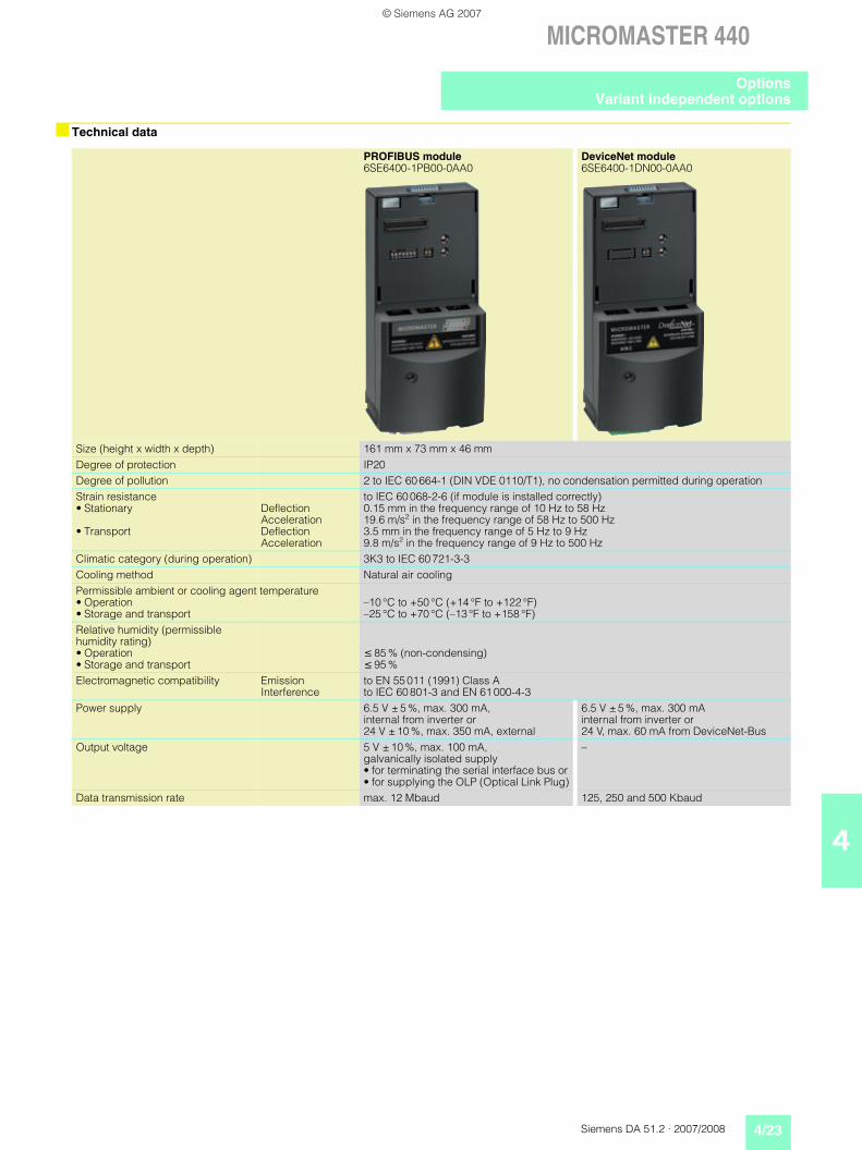
PROFIBUS module6SE6400-1PB00-0AA0
DeviceNet module6SE6400-1DN00-0AA0
Size (height x width x depth) 161 mm x 73 mm x 46 mmDegree of protection IP20Degree of pollution 2 to IEC 60 664-1 (DIN VDE 0110/T1), no condensation permitted during operationStrain resistance• Stationary
• Transport
DeflectionAccelerationDeflectionAcceleration
to IEC 60 068-2-6 (if module is installed correctly) 0.15 mm in the frequency range of 10 Hz to 58 Hz19.6 m/s2 in the frequency range of 58 Hz to 500 Hz3.5 mm in the frequency range of 5 Hz to 9 Hz9.8 m/s2 in the frequency range of 9 Hz to 500 Hz
Climatic category (during operation) 3K3 to IEC 60 721-3-3Cooling method Natural air coolingPermissible ambient or cooling agent temperature• Operation• Storage and transport
–10 °C to +50 °C (+14 °F to +122 °F)–25 °C to +70 °C (–13 °F to +158 °F)
Relative humidity (permissible humidity rating)• Operation• Storage and transport
85 % (non-condensing) 95 %
Electromagnetic compatibility EmissionInterference
to EN 55 011 (1991) Class Ato IEC 60 801-3 and EN 61 000-4-3
Power supply 6.5 V ± 5 %, max. 300 mA, internal from inverter or 24 V ± 10 %, max. 350 mA, external
6.5 V ± 5 %, max. 300 mA internal from inverter or 24 V, max. 60 mA from DeviceNet-Bus
Output voltage 5 V ± 10 %, max. 100 mA, galvanically isolated supply• for terminating the serial interface bus or• for supplying the OLP (Optical Link Plug)
–
Data transmission rate max. 12 Mbaud 125, 250 and 500 Kbaud
OptionsVariant independent options
© Siemens AG 2007
4/24 Siemens DA 51.2 · 2007/2008
MICROMASTER 440
4
Technical data (continued)
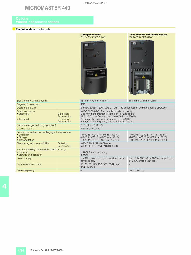
CANopen module6SE6400-1CB00-0AA0
Pulse encoder evaluation module6SE6400-0EN00-0AA0
Size (height x width x depth) 161 mm x 73 mm x 46 mm 161 mm x 73 mm x 42 mmDegree of protection IP20Degree of pollution 2 to IEC 60 664-1 (DIN VDE 0110/T1), no condensation permitted during operationStrain resistance• Stationary
• Transport
DeflectionAccelerationDeflectionAcceleration
to IEC 60 068-2-6 (if module is installed correctly) 0.15 mm in the frequency range of 10 Hz to 58 Hz19.6 m/s2 in the frequency range of 58 Hz to 500 Hz3.5 mm in the frequency range of 5 Hz to 9 Hz9.8 m/s2 in the frequency range of 9 Hz to 500 Hz
Climatic category (during operation) 3K3 to IEC 60 721-3-3Cooling method Natural air coolingPermissible ambient or cooling agent temperature• Operation• Storage• Transportation
–10 °C to +50 °C (+14 °F to +122 °F)–40 °C to +70 °C (–40 °F to +158 °F)–25 °C to +70 °C (–13 °F to +158 °F)
–10 °C to +50 °C (+14 °F to +122 °F)–20 °C to +70 °C (–14 °F to +158 °F)–20 °C to +70 °C (–14 °F to +158 °F)
Electromagnetic compatibility EmissionInterference
to EN 55 011 (1991) Class Ato IEC 60 801-3 and EN 61 000-4-3
Relative humidity (permissible humidity rating)• Operation• Storage and transport
85 % (non-condensing) 95 %
Power supply The CAN bus is supplied from the inverter power supply
5 V ± 5 %, 330 mA or 18 V non-regulated, 140 mA, short-circuit proof
Data transmission rate 10, 20, 50, 125, 250, 500, 800 kbaud and 1 Mbaud
–
Pulse frequency – max. 300 kHz
OptionsVariant independent options
© Siemens AG 2007
Siemens DA 51.2 · 2007/2008 4/25
MICROMASTER 440
4
Selection and ordering data
Type of documentation Language Order No.Docu pack, supplied with each inverter, containing DVD 1) and Getting Started Guide 2) (paper version)
Multilanguage 6SE6400-5AD00-1AP1
Operating instructions(paper version)
German, English, French, Italian, SpanishAvailable as pdf file on the Internet at http://support.automation.siemens.com/WW/view/en/10804926/133300
Parameter list(paper version)
German, English, French, Italian, SpanishAvailable as pdf file on the Internet at http://support.automation.siemens.com/WW/view/en/10804926/133300
1) The DVD contains operating instructions, parameter list, commissioning tools STARTER and DriveMonitor, multilan-guage.
Available on the Internet: DriveMonitor at http://support.automation.siemens.com/WW/view/en/10804984/133100
STARTER at http://support.automation.siemens.com/WW/view/en/10804985/133100
2) Available on the Internet at http://support.automation.siemens.com/WW/view/en/10804926/133300
Documentation
© Siemens AG 2007
4/26 Siemens DA 51.2 · 2007/2008
MICROMASTER 440
4
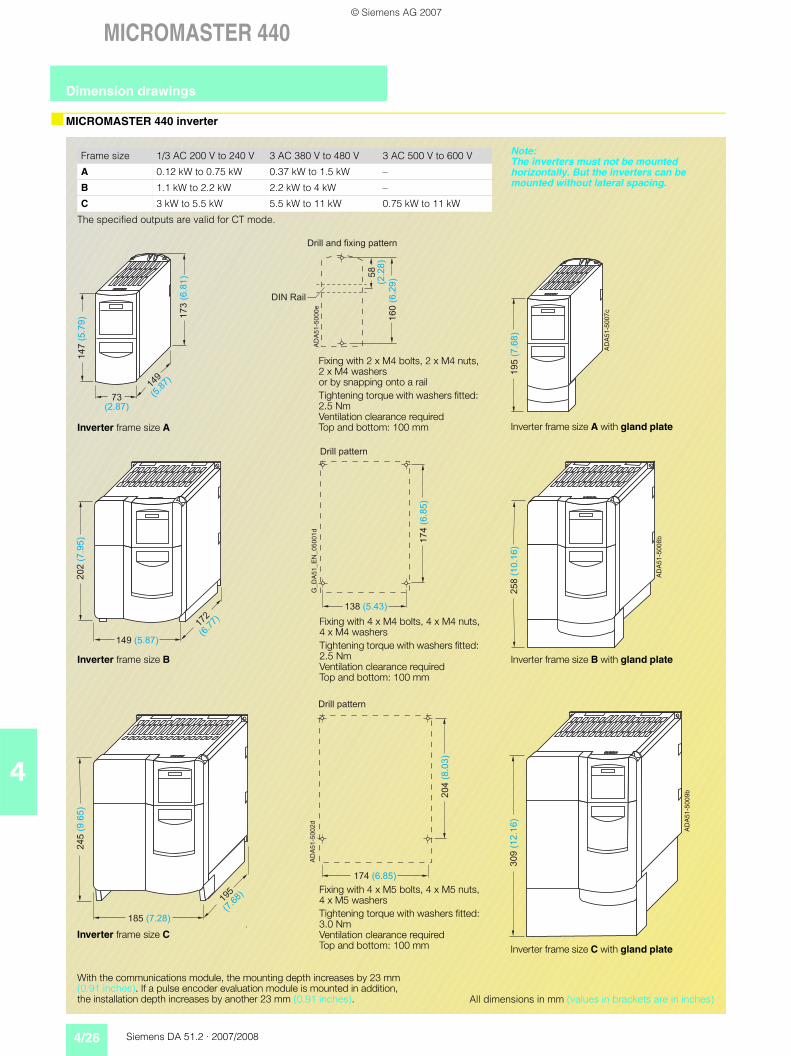
MICROMASTER 440 inverter
Frame size 1/3 AC 200 V to 240 V 3 AC 380 V to 480 V 3 AC 500 V to 600 V
A 0.12 kW to 0.75 kW 0.37 kW to 1.5 kW –
B 1.1 kW to 2.2 kW 2.2 kW to 4 kW –
C 3 kW to 5.5 kW 5.5 kW to 11 kW 0.75 kW to 11 kW
The specified outputs are valid for CT mode.
!"
#!!
!" !
#
!
Inverter frame size A
Fixing with 2 x M4 bolts, 2 x M4 nuts,2 x M4 washersor by snapping onto a railTightening torque with washers fitted: 2.5 NmVentilation clearance requiredTop and bottom: 100 mm
!$
!
Inverter frame size A with gland plate
!#
" #"
!
# !
!
!! Fixing with 4 x M4 bolts, 4 x M4 nuts,
4 x M4 washersTightening torque with washers fitted: 2.5 NmVentilation clearance requiredTop and bottom: 100 mm
Inverter frame size B
%
Inverter frame size B with gland plate
!
#
!
# "
!# Fixing with 4 x M5 bolts, 4 x M5 nuts,4 x M5 washersTightening torque with washers fitted: 3.0 Nm Ventilation clearance requiredTop and bottom: 100 mm
Inverter frame size C
%
"
Inverter frame size C with gland plate
All dimensions in mm (values in brackets are in inches)
With the communications module, the mounting depth increases by 23 mm (0.91 inches). If a pulse encoder evaluation module is mounted in addition, the installation depth increases by another 23 mm (0.91 inches).
Note: The inverters must not be mounted horizontally. But the inverters can be mounted without lateral spacing.
Dimension drawings
© Siemens AG 2007
Siemens DA 51.2 · 2007/2008 4/27
MICROMASTER 440
4
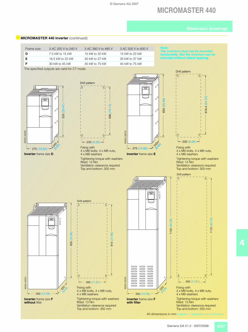
MICROMASTER 440 inverter (continued)
Frame size 3 AC 200 V to 240 V 3 AC 380 V to 480 V 3 AC 500 V to 600 V
D 7.5 kW to 15 kW 15 kW to 22 kW 15 kW to 22 kW
E 18.5 kW to 22 kW 30 kW to 37 kW 30 kW to 37 kW
F 30 kW to 45 kW 45 kW to 75 kW 45 kW to 75 kW
The specified outputs are valid for CT mode.
#!
!
#
# "
%
"
Drill pattern
275 (10.82)
650
(25.
59)
245
(9.6
5)
AD
A51
-502
1b
616.
4 (2
4.27
)
235 (9.25)
Fixing with4 x M8 bolts, 4 x M8 nuts,4 x M8 washersTightening torque with washers fitted: 13 NmVentilation clearance requiredTop and bottom: 300 mm
Inverter frame size E
Fixing with4 x M8 bolts, 4 x M8 nuts,4 x M8 washersTightening torque with washers fitted: 13 NmVentilation clearance requiredTop and bottom: 300 mm
Inverter frame size D
Inverter frame size F without filter
Inverter frame size Fwith filter
%
""#
""!
"
"
"
"%
""!
"
"
#
#"
!
Fixing with4 x M8 bolts, 4 x M8 nuts,4 x M8 washersTightening torque with washers fitted: 13 NmVentilation clearance requiredTop and bottom: 350 mm
Fixing with4 x M8 bolts, 4 x M8 nuts,4 x M8 washersTightening torque with washers fitted: 13 NmVentilation clearance requiredTop and bottom: 350 mm
All dimensions in mm (values in brackets are in inches)
Note: The inverters must not be mounted horizontally. But the inverters can be mounted without lateral spacing.
Dimension drawings
© Siemens AG 2007
4/28 Siemens DA 51.2 · 2007/2008
MICROMASTER 440
4
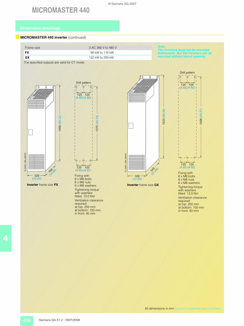
MICROMASTER 440 inverter (continued)
Frame size 3 AC 380 V to 480 V
FX 90 kW to 110 kW
GX 132 kW to 200 kW
The specified outputs are valid for CT mode.
!#
#
" "
"
#
"!
#
"
#
#
#
#
Inverter frame size FX
!
""
"
" "
#
#
"!
#
#
#
#
Inverter frame size GX
Fixing with6 x M8 bolts6 x M8 nuts6 x M8 washersTightening torque with washers fitted: 13.0 NmVentilation clearance required:at top: 250 mmat bottom: 150 mmin front: 40 mm
Fixing with6 x M8 bolts6 x M8 nuts6 x M8 washersTightening torque with washers fitted: 13.0 NmVentilation clearance required:at top: 250 mmat bottom: 150 mmin front: 50 mm
All dimensions in mm (values in brackets are in inches)
Note: The inverters must not be mounted horizontally. But the inverters can be mounted without lateral spacing.
Dimension drawings
© Siemens AG 2007

Siemens DA 51.2 · 2007/2008 4/29
MICROMASTER 440
4
EMC filter
All dimensions in mm (values in brackets are in inches)
%#%
"
&&
"
$
G_
DA
51
_E
N_
00
06
173 (2.87)
56 (2.2)
43.5 (1.71)
20
0(7
.87
)
16
0(6
.3)
18
7(7
.36
)
17
4(6
.85
)2 x M4
G_
DA
51
_E
N_
00
06
2
149 (5.87)
120 (4.72)
50.5 (1.99)
21
3(8
.39
)
17
4(6
.85
)
20
0(7
.87
)
18
7(7
.36
)
4 x M4
138(5.43)
24(0.94)
G_
DA
51
_E
N_
00
06
3
185 (7.28)
156 (6.14)
55 (2.17)
24
5(9
.65
)
20
4(8
.03
)
23
2(9
.13
)
21
9(8
.62
)
4 x M4
174(6.85)
38(1.5)
EMC filter for frame size A For frame size B For frame size C
EMC filterClass AType 6SL3000-
for inverterFrame size (FS)
Dimensions Weight, approx
a a1 b b1 c n3 n4 kg
0BE32-5AA0 FX 270(10.63)
360(14.17)
200(7.87)
240(9.45)
116(4.57)
210(8.27)
220(8.66)
12.3
0BE34-4AA0 GX/GX 270(10.63)
360(14.17)
200(7.87)
240(9.45)
116(4.57)
210(8.27)
220(8.66)
12.3
0BE36-0AA0 GX 310(12.2)
400(15.75)
215(8.46)
265(10.43)
140(5.51)
250(9.84)
240(9.45)
19.0
EMC filter for frame sizes FX and GX
Dimension drawings
© Siemens AG 2007

4/30 Siemens DA 51.2 · 2007/2008
MICROMASTER 440
4
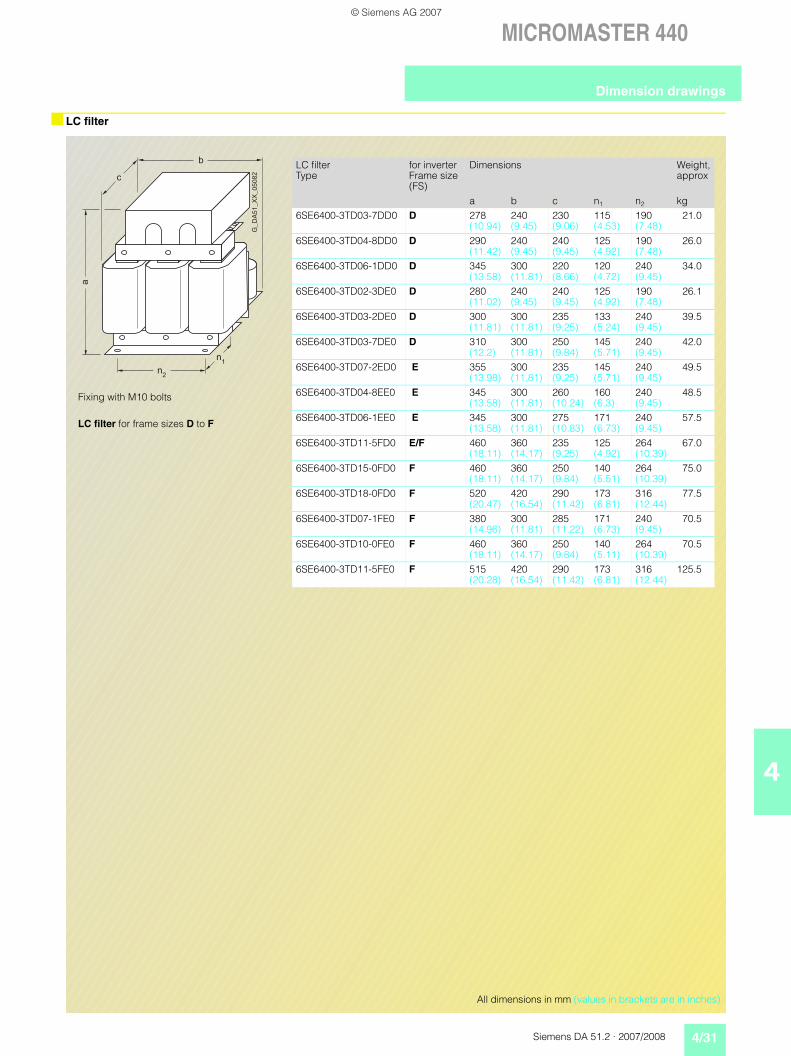
LC filter
!
"
!!
#"
""#"
!!
""
"
"#""
LC filter for frame size A For frame size B
Fixing with M4 bolts Fixing with M4 bolts
!
!"
" #"
#!
All dimensions in mm (values in brackets are in inches)
!
! #
" #
""
"
LC filter for frame size C
Fixing with M5 bolts
"
!#
#
Dimension drawings
© Siemens AG 2007
Siemens DA 51.2 · 2007/2008 4/31
MICROMASTER 440
4
LC filter
Fixing with M10 bolts
LC filter for frame sizes D to F
%
$
&&
LC filterType
for inverterFrame size (FS)
Dimensions Weight, approx
a b c n1 n2 kg6SE6400-3TD03-7DD0 D 278
(10.94)240(9.45)
230(9.06)
115(4.53)
190(7.48)
21.0
6SE6400-3TD04-8DD0 D 290(11.42)
240(9.45)
240(9.45)
125(4.92)
190(7.48)
26.0
6SE6400-3TD06-1DD0 D 345(13.58)
300(11.81)
220(8.66)
120(4.72)
240(9.45)
34.0
6SE6400-3TD02-3DE0 D 280(11.02)
240(9.45)
240(9.45)
125(4.92)
190(7.48)
26.1
6SE6400-3TD03-2DE0 D 300(11.81)
300(11.81)
235(9.25)
133(5.24)
240(9.45)
39.5
6SE6400-3TD03-7DE0 D 310(12.2)
300(11.81)
250(9.84)
145(5.71)
240(9.45)
42.0
6SE6400-3TD07-2ED0 E 355(13.98)
300(11.81)
235(9.25)
145(5.71)
240(9.45)
49.5
6SE6400-3TD04-8EE0 E 345(13.58)
300(11.81)
260(10.24)
160(6.3)
240(9.45)
48.5
6SE6400-3TD06-1EE0 E 345(13.58)
300(11.81)
275(10.83)
171(6.73)
240(9.45)
57.5
6SE6400-3TD11-5FD0 E/F 460(18.11)
360(14.17)
235(9.25)
125(4.92)
264(10.39)
67.0
6SE6400-3TD15-0FD0 F 460(18.11)
360(14.17)
250(9.84)
140(5.51)
264(10.39)
75.0
6SE6400-3TD18-0FD0 F 520(20.47)
420(16.54)
290(11.42)
173(6.81)
316(12.44)
77.5
6SE6400-3TD07-1FE0 F 380(14.96)
300(11.81)
285(11.22)
171(6.73)
240(9.45)
70.5
6SE6400-3TD10-0FE0 F 460(18.11)
360(14.17)
250(9.84)
140(5.11)
264(10.39)
70.5
6SE6400-3TD11-5FE0 F 515(20.28)
420(16.54)
290(11.42)
173(6.81)
316(12.44)
125.5
All dimensions in mm (values in brackets are in inches)
Dimension drawings
© Siemens AG 2007
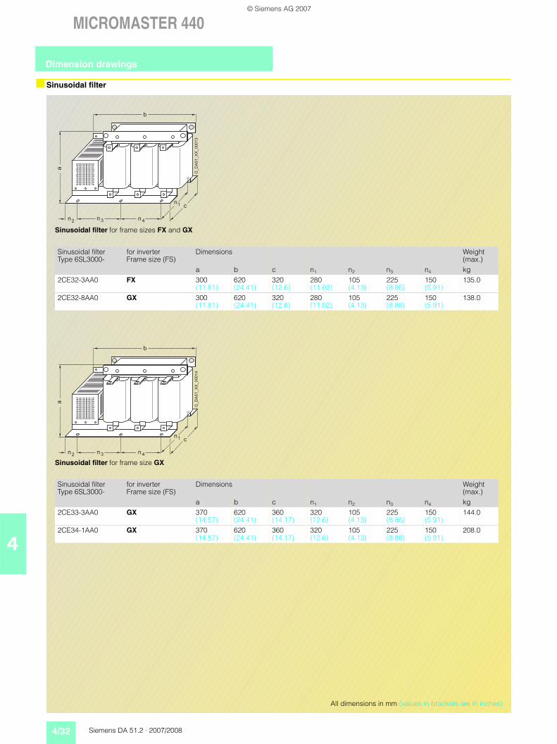
4/32 Siemens DA 51.2 · 2007/2008
MICROMASTER 440
4
Sinusoidal filter
a
nn2 3 4
1
n
n
b
c
G_
DA
51
_X
X_
00
01
3
Sinusoidal filter for frame sizes FX and GX
Sinusoidal filter Type 6SL3000-
for inverter Frame size (FS)
Dimensions Weight (max.)
a b c n1 n2 n3 n4 kg2CE32-3AA0 FX 300
(11.81)620(24.41)
320(12.6)
280(11.02)
105(4.13)
225(8.86)
150(5.91)
135.0
2CE32-8AA0 GX 300(11.81)
620(24.41)
320(12.6)
280(11.02)
105(4.13)
225(8.86)
150(5.91)
138.0
c
G_
DA
51
_X
X_
00
01
4
a
nn2 3 4
1
n
n
b
Sinusoidal filter for frame size GX
Sinusoidal filter Type 6SL3000-
for inverter Frame size (FS)
Dimensions Weight (max.)
a b c n1 n2 n3 n4 kg2CE33-3AA0 GX 370
(14.57)620(24.41)
360(14.17)
320(12.6)
105(4.13)
225(8.86)
150(5.91)
144.0
2CE34-1AA0 GX 370(14.57)
620(24.41)
360(14.17)
320(12.6)
105(4.13)
225(8.86)
150(5.91)
208.0
All dimensions in mm (values in brackets are in inches)
Dimension drawings
© Siemens AG 2007

Siemens DA 51.2 · 2007/2008 4/33
MICROMASTER 440
4
Line commutating chokes
All dimensions in mm (values in brackets are in inches)
G_
DA
51
_X
X_
00
06
4
b
a
c
d e
%
"
$
Line commutating choke for frame size A
For frame sizes B and C
Line commu-tating choke for
Dimensions Weight (max.)
a b c d e kgFrame size A 200
(7.87)75.5(2.97)
50(1.97)
– – 1.4
Frame size B 213(8.39)
150(5.91)
50(1.97)
220(8.66)
233(9.17)
2.2
Frame size C(380–480 V)
245(9.65)
185(7.28)
50(1.97)
264(10.39)
280(11.02)
5.1
Frame size C(500–600 V, 0.75–1.5 kW)
245(9.65)
185(7.28)
50(1.97)
264(10.39)
280(11.02)
3.8
Frame size C(500–600 V, 2.2–4 kW)
245(9.65)
185(7.28)
50(1.97)
264(10.39)
280(11.02)
4.0
Frame size C(500–600 V, 5.5–11 kW)
245(9.65)
185(7.28)
80(3.15)
264(10.39)
280(11.02)
8.0
%
$
Line commutating choke for frame sizes D and E
Line commutating choke for
Dimensions Weight (max.)
a b c kgFrame size D 520
(20.47)275(10.83)
85(3.35)
9.5
Frame size E 650(25.59)
275(10.83)
95(3.74)
17.0
Line commutating choke for inverter frame size F
Line commu-tating choke Type 6SE6400-
for inverterFrame size (FS)
Dimensions Weight (max.)
a b c n1 n2 kg
3CC11-.. .. F 228(8.98)
240(9.45)
141(5.55)
95(3.74)
185(7.28)
25.0
Line commutating choke for inverters of frame sizes FX and GX
Line commu-tating choke Type 6SL3000-
for inverterFrame size (FS)
Dimensions Weight (max.)
a b c n1 n2 kg
0CE32-.... FX 248(9.76)
255(10.04)
203(7.99)
101(3.98)
200(7.87)
24.0
0CE33-.... GX 248(9.76)
255(10.04)
203(7.99)
101(3.98)
200(7.87)
25.0
0CE35-.... GX 269(10.59)
275(10.83)
210(8.27)
118(4.65)
224(8.82)
35.0
Dimension drawings
© Siemens AG 2007

4/34 Siemens DA 51.2 · 2007/2008
MICROMASTER 440
4
Output chokes
%
#
$
Output choke for frame size A6SE6400-3TC00-4AD26SE6400-3TC00-4AD3
For frame sizes B and C6SE6400-3TC01-0BD36SE6400-3TC01-8CE36SE6400-3TC03-2CD3
&&
%
$
Output choke Type 6SE6400-
Dimensions Weight (max.)
a b c kg3TC00-4AD2 200
(7.87)75.5(2.97)
110(4.33)
1.9
3TC00-4AD3 200(7.87)
75.5(2.97)
50(1.97)
1.3
3TC01-0BD3 213(8.39)
150(5.91)
80(3.15)
4.1
3TC01-8CE3 245(9.65)
185(7.28)
110(4.33)
10.8
3TC03-2CD3 245(9.65)
185(7.28)
80(3.15)
6.6
Output chokes for inverters of frame sizes D, E and F
Output chokeType 6SE6400-
for inverterFrame size (FS)
Dimensions Weight (max.)to DIN 41 308
a b c n1 n2 kg3TC03-2DE0 D 210
(8.27)225 (8.86)
179 (7.05)
94 (3.70)
176 (6.93)
16.0
3TC03-8DD0 D 210 (8.27)
225 (8.86)
179 (7.05)
94 (3.70)
176 (6.93)
16.1
3TC05-4DD0 D 210 (8.27)
225 (8.86)
150 (5.91)
70 (2.76)
176 (6.93)
10.7
3TC06-2FE0 F 269 (10.59)
300 (11.81)
220 (8.66)
118 (4.65)
224 (8.82)
33.9
3TC07-5ED0 E 248 (9.76)
270 (10.63)
209 (8.23)
101 (3.98)
200 (7.87)
24.9
3TC08-0ED0 E 210 (8.27)
225 (8.86)
150 (5.91)
70 (2.76)
176 (6.93)
10.4
3TC08-8FE0 F 321 (12.64)
350 (13.78)
288 (11.34)
138 (5.43)
264 (10.39)
51.5
3TC14-5FD0 F 321 (12.64)
350 (13.78)
288 (11.34)
138 (5.43)
264 (10.39)
51.5
3TC15-4FD0 F 248 (9.76)
270 (10.63)
209 (8.23)
101 (3.98)
200 (7.87)
24.0
Output chokes for inverters of frame sizes FX and GX
Output chokeType 6SL3000-
for inverterFrame size (FS)
Dimensions Weight (max.)
a b c n1 n2 kg2BE32-1AA0 FX 285
(11.22)300(11.81)
257(10.12)
163(6.42)
224(8.82)
60.0
2BE32-6AA0 FX 315(12.4)
300(11.81)
277(10.91)
183(7.2)
224(8.82)
66.0
2BE33-2AA0 GX 285(11.22)
300(11.81)
257(10.12)
163(6.42)
224(8.82)
62.0
2BE33-8AA0 GX 285(11.22)
300(11.81)
277(10.91)
183(7.2)
224(8.82)
73.0
2BE35-0AA0 GX 365(14.37)
300(11.81)
277(10.91)
183(7.2)
224(8.82)
100.0
All dimensions in mm (values in brackets are in inches)
Dimension drawings
© Siemens AG 2007