afs manual -6/3/03 - · pdf fileafs 224 introduction afs 224 user manual for more information...
TRANSCRIPT
User Manual
Du a l C h a n n e l A d v a n c e d F e e d b a c k S u p p r e s s i o n P r o c e s s o r
®
AFS™ 224
WARNING FOR YOUR PROTECTIONREAD THESE INSTRUCTIONS:
KEEP THESE INSTRUCTIONS
HEED ALL WARNINGS
FOLLOW ALL INSTRUCTIONS
DO NOT USE THIS APPARATUS NEAR WATER
CLEAN ONLY WITH A DRY CLOTH.
DO NOT BLOCK ANY OF THE VENTILATION OPENINGS. INSTALL IN ACCORDANCE WITHTHE MANUFACTURER’S INSTRUCTIONS.
DO NOT INSTALL NEAR ANY HEAT SOURCES SUCH AS RADIATORS, HEAT REGISTERS,STOVES, OR OTHER APPARATUS (INCLUDING AMPLIFIERS) THAT PRODUCE HEAT.
ONLY USE ATTACHMENTS/ACCESSORIES SPECIFIED BY THE MANUFACTURER.
UNPLUG THIS APPARATUS DURING LIGHTNING STORMS OR WHEN UNUSED FOR LONGPERIODS OF TIME.
Do not defeat the safety purpose of the polarized or grounding-type plug. A polar-ized plug has two blades with one wider than the other. A grounding type plug hastwo blades and a third grounding prong. The wide blade or third prong are pro-vided for your safety. If the provided plug does not fit your outlet, consult an elec-trician for replacement of the obsolete outlet.
Protect the power cord from being walked on or pinched particularly at plugs, con-venience receptacles, and the point where they exit from the apparatus.
Use only with the cart stand, tripod bracket, or table specified by the manufacture,or sold with the apparatus. When a cart is used, use caution when moving thecart/apparatus combination to avoid injury from tip-over.
Refer all servicing to to qualified service personnel. Servicing is required whenthe apparatus has been damaged in any way, such as power-supply cord or plug isdamaged, liquid has been spilled or objects have fallen into the apparatus, the appa-ratus has been exposed to rain or moisture, does not operate normally, or has beendropped.
POWER ON/OFF SWITCH: For products provided with a power switch, the powerswitch DOES NOT break the connection from the mains.
MAINS DISCONNECT: The plug shall remain readily operable. For rack-mount orinstallation where plug is not accessible, an all-pole mains switch with a contactseparation of at least 3 mm in each pole shall be incorporated into the electricalinstallation of the rack or building.
FOR UNITS EQUIPPED WITH EXTERNALLY ACCESSIBLE FUSE RECEPTACLE: Replace fusewith same type and rating only.
MULTIPLE-INPUT VOLTAGE: This equipment may require the use of a different linecord, attachment plug, or both, depending on the available power source at instal-lation. Connect this equipment only to the power source indicated on the equipmentrear panel. To reduce the risk of fire or electric shock, refer servicing to qualifiedservice personnel or equivalent.
This Equipment is intended for rack mount use only.
SAFETY INSTRUCTIONS
NOTICE FOR CUSTOMERS IF YOUR UNIT IS EQUIPPEDWITH A POWER CORD.
WARNING: THIS APPLIANCE MUST BE EARTHED.
The cores in the mains lead are coloured in accordance withthe following code:
GREEN and YELLOW - Earth BLUE - Neutral BROWN - Live
As colours of the cores in the mains lead of this appliance maynot correspond with the coloured markings identifying the ter-minals in your plug, proceed as follows:
• The core which is coloured green and yellow mustbe connected to the terminal in the plug markedwith the letter E, or with the earth symbol, orcoloured green, or green and yellow.
• The core which is coloured blue must be connect-ed to the terminal marked N or coloured black.
• The core which is coloured brown must be con-nected to the terminal marked L or coloured red.
This equipment may require the use of a different line cord,attachment plug, or both, depending on the available powersource at installation. If the attachment plug needs to bechanged, refer servicing to qualified service personnel whoshould refer to the table below. The green/yellow wire shall beconnected directly to the units chassis.
WARNING: If the ground is defeated, certain fault conditions inthe unit or in the system to which it is connected can result infull line voltage between chassis and earth ground. Severe injuryor death can then result if the chassis and earth ground aretouched simultaneously.
LIVE
E
NEUTRAL
EARTH GND
CONDUCTOR
L
N
BROWN
BLUE
GREEN/YEL
BLACK
Normal Alt
WIRE COLOR
WHITE
GREEN
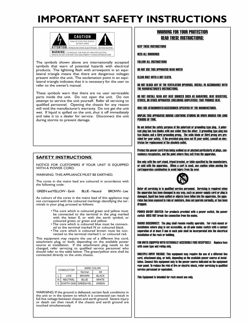
The symbols shown above are internationally acceptedsymbols that warn of potential hazards with electricalproducts. The lightning flash with arrowpoint in an equi-lateral triangle means that there are dangerous voltagespresent within the unit. The exclamation point in an equi-lateral triangle indicates that it is necessary for the user torefer to the owner’s manual.
These symbols warn that there are no user serviceableparts inside the unit. Do not open the unit. Do notattempt to service the unit yourself. Refer all servicing toqualified personnel. Opening the chassis for any reasonwill void the manufacturer’s warranty. Do not get the unitwet. If liquid is spilled on the unit, shut it off immediatelyand take it to a dealer for service. Disconnect the unitduring storms to prevent damage.
CAUT ION
ATTENT ION: RISQUE DE CHOC ELECTRIQUE - NE PAS OUVRIR
WARNING: TO REDUCE THE R ISK OF F IRE OR ELECTRICSHOCK DO NOT EXPOSE TH IS EQUIPMENT TO RA IN OR MOISTURE
RISK OF ELECTRIC SHOCKDO NOT OPEN
IMPORTANT SAFETY INSTRUCTIONS
U.K. MAINS PLUG WARNINGA molded mains plug that has been cut off from the cord is unsafe.Discard the mains plug at a suitable disposal facility. NEVER UNDERANY CIRCUMSTANCES SHOULD YOU INSERT A DAMAGED OR CUTMAINS PLUG INTO A 13 AMP POWER SOCKET. Do not use themains plug without the fuse cover in place. Replacement fuse coverscan be obtained from your local retailer. Replacement fuses are 13amps and MUST be ASTA approved to BS1362.
IMPORTANT SAFETY INSTRUCTIONS
ELECTROMAGNETICCOMPATIBILITY
This unit conforms to the ProductSpecifications noted on the Declarationof Conformity. Operation is subject tothe following two conditions:
• this device may not cause harmfulinterference, and
• this device must accept any interfer-ence received, including interferencethat may cause undesired operation.
Operation of this unit within significantelectromagnetic fields should be avoided.
• use only shielded interconnectingcables.
DECLARATION OFCONFORMITY
Manufacturer’s Name: dbx Professional ProductsManufacturer’s Address: 8760 S. Sandy Parkway
Sandy, Utah 84070, USA
declares that the product:
Product name: dbx AFS 224 Note: Product name may be suffixed by the
letters-EU.
Product option: None
conforms to the following Product Specifications:
Safety: IEC 60065 (1998)
EMC: EN 55013 (1990)EN 55020 (1991)
Supplementary Information:
The product herewith complies with the requirements of the LowVoltage Directive 72/23/EEC and the EMC Directive 89/336/EEC asamended by Directive 93/68/EEC.
Vice-President of Engineering 8760 S. Sandy ParkwaySandy, Utah 84070, USADate: June 9, 2003
European Contact: Your local dbx Sales and Service Office or
Harman Music Group8760 South Sandy ParkwaySandy, Utah 84070 USAPh: (801) 566-8800Fax: (801) 568-7583
Table of ContentsAFS 224Table of Contents
Defining the AFS 224 ..............................................i
Service Contact Info ...............................................ii
Warranty ..................................................................ii
Installation Recommendations...............................1
Basic Connections ..................................................1
Rear Panel Connections .........................................2
Front Panel Connections........................................2
User Setup...............................................................3
Applications ............................................................7
Block Diagram......................................................10
Specifications ........................................................11
®
AFS 224 User ManualTable of Contents
®
AFS 224 OperationAFS 224
Introduction
®
AFS 224 User Manuali
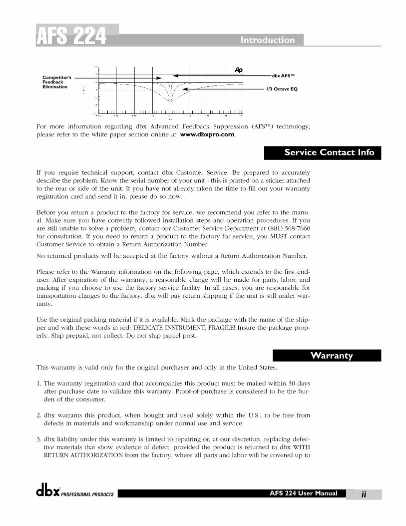
AFS 224Congratulations on your purchase of the dbx Professional Products AFS 224. The AFS 224Advanced Feedback Suppression processor was designed to provide state-of-the-art feedbackelimination processing, while maintaining a simple and intuitive control interface. From thepowerful DSP module to the no-nonsense user interface, the AFS 224 provides all the process-ing and control necessary for both installation and live use. The AFS 224 is an absolute mustfor any live sound application.
Ten and twelve filter feedback elimination processors have become the de facto standard, butthe engineering staff at dbx have never been content residing in the neighborhood of the sta-tus quo. So, to raise the bar once again, they went out and developed a dedicated feedbacksuppression processor that offers up to 24 filters per channel with widths as narrow as 1/80 ofan octave. To achieve these staggering numbers dbx utilized their patent-pending AFS tech-nology that had previously only been available in the upper echelon line of products and madeit available in this stand-alone processor. In addition to the plethora of feedback suppressionfilters available, the AFS 224 also offers selectable modes, live filter lift, and types of filtration,which are all readily available via the intuitive user interface front panel. This manual will beyour guide to understanding the full functionality of the powerful AFS 224 series.
The dbx AFS 224 provide the user with the following features:
• dbx’s patent-pending Advanced Feedback Suppression (AFS™)
technology
• 24 Programmable Filters per Channel
• Stereo or Dual Independent Channel Processing
• Live and Fixed Filter Modes
• Selectable Filter Lift Times
• Application-specific filter types include:Speech;Music Low,Med and High
• Input Channel Metering
• 24 Segment Filter Metering per Channel
• XLR and TRS Electronically Balanced Input and Outputs
The AFS 224 AdvantageKey features that make the AFS 224 are its Fixed and Live modes of operation, as well as theunits Filter Lift capabilities. The Live Mode of operation continuously updates filter placementwhich provides flexibility during a performance. The Filter Lift feature automatically removesfilter assignments that are no longer necessary, which in turn, maximizes sonic integrity.
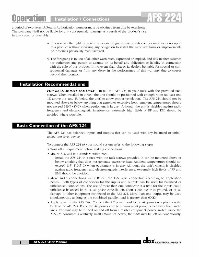
The AFS 224 allows the user to optimize the elimination of feedback. In the past, graphic equal-izers were used to eliminate feedback from a system. This was an acceptable method for elim-inating feedback, but when this method was precision tested, the result clearly showed that asingle 1/3 octave EQ slider was removing approximately half of the signal power. With the AFS,the unit removes the feedback automatically and the proprietary, precision AFS filters removeonly a fraction of the frequency spectrum. The diagram on the following page shows AFS asopposed to competitive feedback eliminators and conventional graphic EQs:
Defining the AFS 224
INTRODUCTION
®
IntroductionAFS 224
AFS 224 User Manual
For more information regarding dbx Advanced Feedback Suppression (AFS™) technology,please refer to the white paper section online at: www.dbxpro.com.
If you require technical support, contact dbx Customer Service. Be prepared to accuratelydescribe the problem. Know the serial number of your unit - this is printed on a sticker attachedto the rear or side of the unit. If you have not already taken the time to fill out your warrantyregistration card and send it in, please do so now.
Before you return a product to the factory for service, we recommend you refer to the manu-al. Make sure you have correctly followed installation steps and operation procedures. If youare still unable to solve a problem, contact our Customer Service Department at (801) 568-7660for consultation. If you need to return a product to the factory for service, you MUST contactCustomer Service to obtain a Return Authorization Number.
No returned products will be accepted at the factory without a Return Authorization Number.
Please refer to the Warranty information on the following page, which extends to the first end-user. After expiration of the warranty, a reasonable charge will be made for parts, labor, andpacking if you choose to use the factory service facility. In all cases, you are responsible fortransportation charges to the factory. dbx will pay return shipping if the unit is still under war-ranty.
Use the original packing material if it is available. Mark the package with the name of the ship-per and with these words in red: DELICATE INSTRUMENT, FRAGILE! Insure the package prop-erly. Ship prepaid, not collect. Do not ship parcel post.
This warranty is valid only for the original purchaser and only in the United States.
1. The warranty registration card that accompanies this product must be mailed within 30 daysafter purchase date to validate this warranty. Proof-of-purchase is considered to be the bur-den of the consumer.
2. dbx warrants this product, when bought and used solely within the U.S., to be free fromdefects in materials and workmanship under normal use and service.
3. dbx liability under this warranty is limited to repairing or, at our discretion, replacing defec-tive materials that show evidence of defect, provided the product is returned to dbx WITHRETURN AUTHORIZATION from the factory, where all parts and labor will be covered up to
Warranty
Service Contact Info
ii
Competitor’sFeedbackElimination 1/3 Octave EQ
dbx AFS™
Installation / Connections
®
AFS 224 User Manual1
AFS 224a period of two years. A Return Authorization number must be obtained from dbx by telephone.The company shall not be liable for any consequential damage as a result of the product's usein any circuit or assembly.
4. dbx reserves the right to make changes in design or make additions to or improvements uponthis product without incurring any obligation to install the same additions or improvementson products previously manufactured.
5. The foregoing is in lieu of all other warranties, expressed or implied, and dbx neither assumesnor authorizes any person to assume on its behalf any obligation or liability in connectionwith the sale of this product. In no event shall dbx or its dealers be liable for special or con-sequential damages or from any delay in the performance of this warranty due to causesbeyond their control.
FOR RACK MOUNT USE ONLY - Install the AFS 224 in your rack with the provided rackscrews. When installed in a rack, the unit should be positioned with enough room (at least one1U above the and 1U below the unit) to allow proper ventilation. The AFS 224 should not bemounted above or below anything that generates excessive heat. Ambient temperatures shouldnot exceed 1130F (450C) when equipment is in use. Although the unit is shielded against radiofrequency and electromagnetic interference, extremely high fields of RF and EMI should beavoided where possible.
The AFS 224 has balanced inputs and outputs that can be used with any balanced or unbal-anced line-level device.
To connect the AFS 224 to your sound system refer to the following steps:
• Turn off all equipment before making connections.
• Mount AFS 224 in a standard-width rack.Install the AFS 224 in a rack with the rack screws provided. It can be mounted above orbelow anything that does not generate excessive heat. Ambient temperatures should notexceed 113° F (45°C) when equipment is in use. Although the unit’s chassis is shieldedagainst radio frequency and electromagnetic interference, extremely high fields of RF andEMI should be avoided.
• Make audio connections via XLR, or 1/4” TRS jacks connectors according to applicationneeds. Both types of connectors for the inputs and outputs can be used for balanced orunbalanced connections. The use of more than one connector at a time for the inputs couldunbalance balanced lines, cause phase cancellation, short a conductor to ground, or causedamage to other equipment connected to the AFS 224. More than one output may be usedsimultaneously as long as the combined parallel load is greater than 600Ω.
• Apply power to the AFS 224. Connect the AC power cord to the AC power receptacle on theback of the AFS 224. Route the AC power cord to a convenient power outlet away from audiolines. The unit may be turned on and off from a master equipment power switch. Since theAFS 224 consumes a relatively small amount of power, the units may be left on continuously.
Basic Connection of the AFS 224
Installation Recommendations
Operation

Rear and Front Panels OperationAFS 224
®
AFS 224 User Manual 2
AFS 224 Rear
Power Cord Receptacle: Connects AC power to the AFS 224.
Input Connectors: Two types of input connectors are provided for input connections:female locking XLR type connectors, and 1/4” tip-ring-sleeve phone jack connectors. Themaximum input level that the processor can accept is +20dBu (ref: 0.775Vrms).
Operating Level Switch: This button allows you to select between either +4dBu or -10dBV nominal operating level.
Output Connectors: Two types of output connectors are provided for output connec-tions: male XLR type connectors, and 1/4” tip-ring-sleeve phone jack connectors.
AFS 224 Front
Input Level Bar Graph: These four LEDs indicate input level of the AFS 224. Input levelLEDs range from -10 to +18dBu.
IMPORTANT - For maximum performance and proper operation, the average input sig-nal should consistently light the 0 dBu LED, with the +10 dBu LED occasionally lighting.
Clip LED: This LED indicates that there is signal clipping at the input.
Bypass: This button bypasses the notch filters in the signal path by pressing once. Pressingand holding the Bypass button is used to reset the filters. For more information regardingfilter reset, please see the Clearing Filters in the User Setup Section.
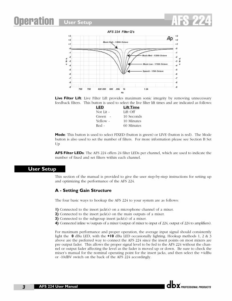
Type: This button is used to select the AFS type and to link Channel A and Channel B.The AFS 224 offers several feedback suppression types, which are Speech, Music Low,Music Medium and Music High. Each selected Type controls the width of the notch filter used to remove the feedback. MUSIC HIGH uses very narrow notch filters minimiz-ing the effect on the music, whereas the SPEECH type uses much wider notch filters allow-ing the AFS 224 to work faster. The Type, LED color and Frequency Q are listed belowand a representative filter Q graph is shown on the next page.
Type LED QMusic High: Red 1/80th OctaveMusic Med: Yellow 1/20th OctaveMusic Low: Green 1/10th OctaveSpeech: Not Lit 1/5th Octave
Front Panel
Rear Panel
User Setup
®
AFS 224 User Manual3
Operation AFS 224
Live Filter Lift: Live Filter Lift provides maximum sonic integrity by removing unnecessaryfeedback filters. This button is used to select the live filter lift times and are indicated as follows:
LED Lift TimeNot Lit - Lift OffGreen - 10 SecondsYellow - 10 MinutesRed - 60 Minutes
Mode: This button is used to select FIXED (button is green) or LIVE (button is red). The Modebutton is also used to set the number of filters. For more information please see Section B SetUp
AFS Filter LEDs: The AFS 224 offers 24 filter LEDs per channel, which are used to indicate thenumber of fixed and set filters within each channel.
This section of the manual is provided to give the user step-by-step instructions for setting upand optimizing the performance of the AFS 224.
A - Setting Gain Structure
The four basic ways to hookup the AFS 224 to your system are as follows:
1) Connected to the insert jack(s) on a microphone channel of a mixer.2) Connected to the insert jack(s) on the main outputs of a mixer.3) Connected to the subgroup insert jack(s) of a mixer.4) Connected inline w/outputs of a mixer (output of mixer to input of 224, output of 224 to amplifiers).
For maximum performance and proper operation, the average input signal should consistentlylight the 0 dBu LED, with the +10 dBu LED occasionally lighting. Hookup methods 1, 2 & 3above are the preferred way to connect the AFS 224 since the insert points on most mixers arepre output fader. This allows the proper signal level to be fed to the AFS 224 without the chan-nel or output fader affecting the level as the fader is moved up or down. Be sure to check themixer’s manual for the nominal operating point for the insert jacks, and then select the +4dBuor -10dBV switch on the back of the AFS 224 accordingly.
User Setup
AFS 224 Filter Q's
Speech - 1/5th Octave
Music Low - 1/10th Octave
Music Med - 1/20th Octave
Music High - 1/80th Octave
-9
+3
-8
-7
-6
-5
-4
-3
-2
-1
-0
+1
+2
d
B
u
-9
+3
-8
-7
-6
-5
-4
-3
-2
-1
-0
+1
+2
d
B
u
700 1.2k750 820 850 900 .95k 1k
Hz
®
If no insert points are available, then method 4 would be utilized. In this situation, be surethat the AFS 224 input level allows the 0 and +10 dBu LEDS to light as indicated above. Theinput level to the amplifiers may have to be reduced in this situation so that they are not over-driven by the signal from the AFS 224.
B – Setup ModeThe AFS 224 setup mode is used to set the Total Number of Filters and the Number of Fixed Filtersin each channel. The number of Live filters is the difference between the Total Number of Filtersand the Number of Fixed filters (Live filters = Total Filters-Fixed filters). Note: If channels arelinked (See F-2 Linking Channels) the setup will assign the same number of filters to channel 1and 2.
B-1 Entering Setup ModePress and hold the channel 1 <MODE> button until the Filter LED's light from left to rightand repeat. Release the channel 1 <MODE> button to enter the Setup Mode. This is indi-cated by the <MODE> button lighting yellow. You are now in the Set Total Number of Filtersmode.
B-2 Selecting the Total Number of FiltersThe Set Total Number of Filters mode is indicated by the channel <MODE> button lightingyellow when in the Setup mode. The current setting for the Total Number of Filters is indi-cated by the number of Filter LED's lit for that channel. To change the Total Number of Filtersuse the channel <LIVE FILTER LIFT> button to increment and the <TYPE> button to decre-ment the number of filters. Each press of the button will increment or decrement the TotalNumber of Filters. Press and hold each button to slowly increment or decrement the num-ber.Warning: Changing the Total Number of Filters may remove feedback filters already set.
B-3 Selecting the Number of Fixed FiltersUse the selected channel <MODE> button to toggle to the Set Number of Fixed Filters modeindicated by the selected channel’s <MODE> button, which will light green. The current set-ting for the Number of Fixed Filters is indicated by the number of Filter LED's lit for that chan-nel. To change the number of Fixed Filters, use the selected channel’s <LIVE FILTER LIFT>button to increment and the <TYPE> button to decrement the number of filters. Each pressof the button will increment or decrement the Total Number of Fixed Filters. Press and holdeach button to slowly increment or decrement the number. Pressing the selected channel ‘s<MODE> button will toggle between the Set Total Number of Filters and the Set Number ofFixed Filters mode for each channel. If the channels of the AFS 224 are linked (see F-2Linking Channels) the above procedure will set the same number of filters for both channels.Warning: Changing the Number of Fixed Filters may remove feedback filters already set.
B-4 Exit Setup ModeTo exit the setup mode and return to operation mode press and hold the channel 1 <MODE>button until the Filter LED's light from left to right and repeat (same as entering Setup mode).
C - Using Fixed modeThe AFS 224 offers two main modes of operation, Fixed and Live. Fixed mode is used to detectand remove feedback problems in the system due to microphone placement, room modes etc.Once set these filters are not removed until reset or cleared. Live mode detects and removesfeedback during a performance or event.
User Setup OperationAFS 224
AFS 224 User Manual 4
User Setup
®
3AFS 224 User Manual5
Operation AFS 224C-1 Ringing out a systemFixed mode filters are set before a performance in a process called "ringing out a system".This is done after all other system EQ'ing has been done. First, bring down the main mix,turn off all music sources and open all the mics. Place the AFS 224 into fixed mode bypressing the <MODE> button for the channel. A <MODE> button lighting green indicatesFixed mode for that channel. Select the channel’s filter type by pressing the channel’s<TYPE> button. See Using Types in Fixed mode below. Slowly turn up the main mix,raising the gain of the system, until feedback occurs. The AFS 224 will detect and removefeedback by placing notch filters at the feedback frequency. Continue to slowly raise the gain until all feedback has been eliminated or all fixed filters have been used, this will be indicated by the flashing <MODE> button.
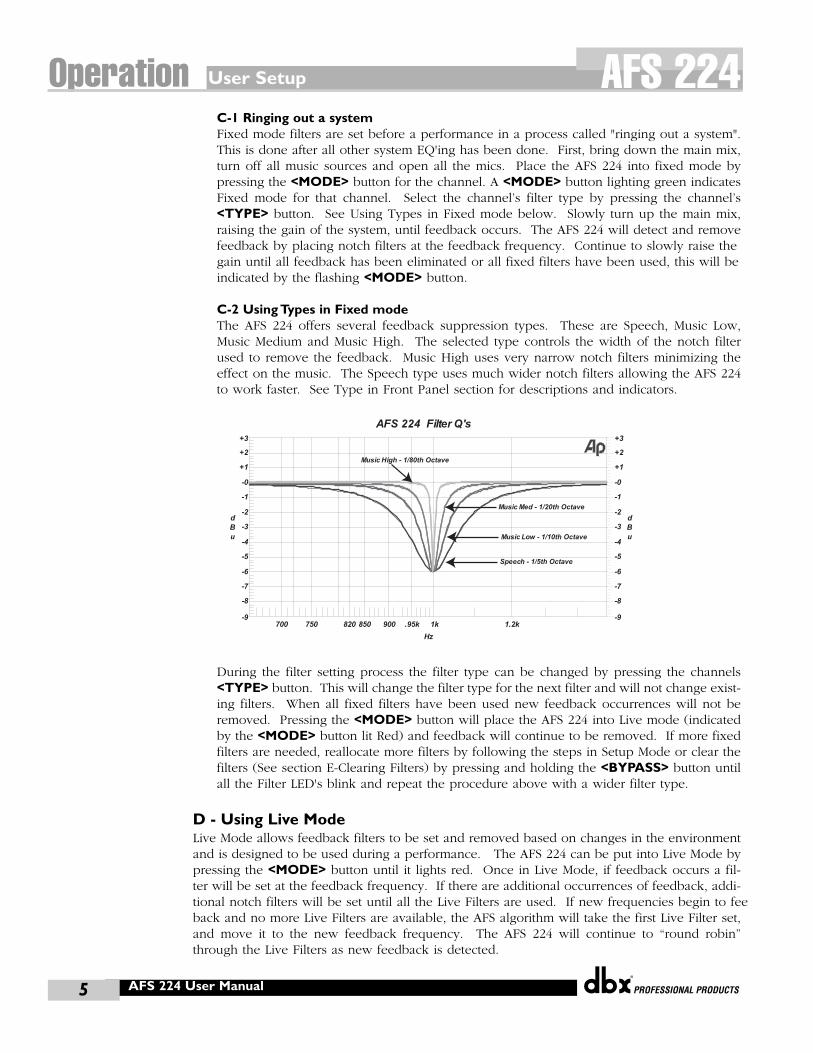
C-2 Using Types in Fixed modeThe AFS 224 offers several feedback suppression types. These are Speech, Music Low,Music Medium and Music High. The selected type controls the width of the notch filterused to remove the feedback. Music High uses very narrow notch filters minimizing theeffect on the music. The Speech type uses much wider notch filters allowing the AFS 224to work faster. See Type in Front Panel section for descriptions and indicators.
During the filter setting process the filter type can be changed by pressing the channels<TYPE> button. This will change the filter type for the next filter and will not change exist-ing filters. When all fixed filters have been used new feedback occurrences will not beremoved. Pressing the <MODE> button will place the AFS 224 into Live mode (indicatedby the <MODE> button lit Red) and feedback will continue to be removed. If more fixedfilters are needed, reallocate more filters by following the steps in Setup Mode or clear thefilters (See section E-Clearing Filters) by pressing and holding the <BYPASS> button untilall the Filter LED's blink and repeat the procedure above with a wider filter type.
D - Using Live ModeLive Mode allows feedback filters to be set and removed based on changes in the environmentand is designed to be used during a performance. The AFS 224 can be put into Live Mode bypressing the <MODE> button until it lights red. Once in Live Mode, if feedback occurs a fil-ter will be set at the feedback frequency. If there are additional occurrences of feedback, addi-tional notch filters will be set until all the Live Filters are used. If new frequencies begin to feeback and no more Live Filters are available, the AFS algorithm will take the first Live Filter set,and move it to the new feedback frequency. The AFS 224 will continue to “round robin”through the Live Filters as new feedback is detected.
AFS 224 Filter Q's
Speech - 1/5th Octave
Music Low - 1/10th Octave
Music Med - 1/20th Octave
Music High - 1/80th Octave
-9
+3
-8
-7
-6
-5
-4
-3
-2
-1
-0
+1
+2
d
B
u
-9
+3
-8
-7
-6
-5
-4
-3
-2
-1
-0
+1
+2
d
B
u
700 1.2k750 820 850 900 .95k 1k
Hz
User Setup OperationAFS 224
®
AFS 224 User Manual 6
D-1 Using Live Filter LiftLive Filter Lift provides maximum sonic integrity by removing unnecessary feedback filters.The Live Filter Lift function provides a timer for each of the Live Filters. This timer length canbe adjusted by pressing the <LIVE FILTER LIFT> button, and can be switched between off,1 minute, 10 minutes or 60 minutes. The filter lift default time is 10 minutes from the facto-ry. If Live Filter Lift is on, once a filter’s time period has expired, the AFS algorithm will checkto see if the feedback filter is still necessary. If no longer needed, the notch filter will thenslowly lift. If the filter is still required to eliminate feedback, the timer will be reset. If theLive Filter Lift is off, the notch filters will remain in place until they are cleared, or until need-ed for other frequencies.
D-2 Using Types in Live ModeAs in Fixed Mode, the AFS 224 offers several feedback suppression types. These types con-trol the width of the notch filter used to remove the feedback. The Speech type uses widernotch filters allowing the AFS 224 to work faster. The Music types provide sharper notch fil-ters than the Speech type, with up to 1/80th of an octave in the Music High type (see AFS fil-ter Q graph on the previous page). Pressing the <TYPE> button switches between the dif-ferent types. You can select different types for both Live and Fixed Mode.
E - Clearing Filters (Fixed and Live)To clear the Live filters, press and hold the <BYPASS> button on the selected channel for approx-imately two seconds. The currently assigned live filter LEDs will flash. If you wish to clear onlythe Live filters, release <BYPASS> button at this time. If you wish to reset all filters, continue tohold the <BYPASS> button an additional two seconds until all filter LEDs are flashing. At thispoint, release the <BYPASS> button and all filters will be cleared.
F - Other FunctionsThe AFS 224 also offers the security feature of front panel lockout and the ability to link channels.The following information provides instruction for both procedures.
F- 1 Front Panel LockoutTo lockout all access to the front panel of the AFS 224, press and hold the channel 1 <LIVEFILTER LIFT> button until all of the filter LEDs light from outside to inside. To unlock thefront panel lockout, press and hold the channel 1 <LIVE FILTER LIFT> button until the LEDslight from the inside to the outside.
F-2 Linking ChannelsTo link both channels, press and hold the Channel 1 <TYPE> button until all button LED’sblink will set the unit into LINKED mode. As feedback in either channel occurs, notch filterswill be placed in both channels to remove feedback. To unlink channels, press and hold thechannel 1 <TYPE> button. After the unit is unlinked, both channels will behave indepen-dently.
Application Guide
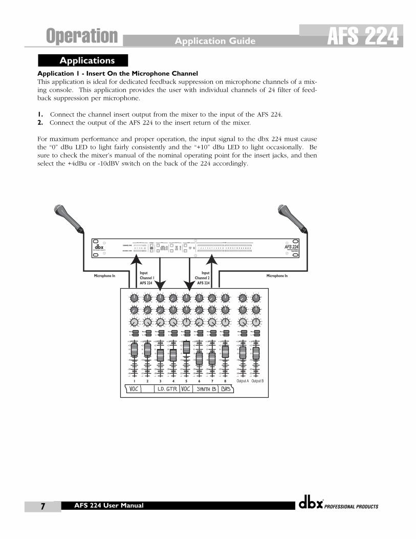
Application 1 - Insert On the Microphone ChannelThis application is ideal for dedicated feedback suppression on microphone channels of a mix-ing console. This application provides the user with individual channels of 24 filter of feed-back suppression per microphone.
1. Connect the channel insert output from the mixer to the input of the AFS 224. 2. Connect the output of the AFS 224 to the insert return of the mixer.
For maximum performance and proper operation, the input signal to the dbx 224 must causethe “0” dBu LED to light fairly consistently and the “+10” dBu LED to light occasionally. Besure to check the mixer’s manual of the nominal operating point for the insert jacks, and thenselect the +4dBu or -10dBV switch on the back of the 224 accordingly.
Pan
Mute
-10
0
+5
+10
-20
-30-∞
-5
L / R
Mute
L / R
Mute
L / R
Mute
L / R
-5
-4
-3
-2-1 0 +1
+2
+3
+4
+5 Pan-5
-4
-3
-2-1 0 +1
+2
+3
+4
+5 Pan-5
-4
-3
-2-1 0 +1
+2
+3
+4
+5 Pan-5
-4
-3
-2-1 0 +1
+2
+3
+4
+5 Pan-5
-4
-3
-2-1 0 +1
+2
+3
+4
+5 Pan-5
-4
-3
-2-1 0 +1
+2
+3
+4
+5 Pan-5
-4
-3
-2-1 0 +1
+2
+3
+4
+5 Pan-5
-4
-3
-2-1 0 +1
+2
+3
+4
+5
1 2 3 4
-10
0
+5
+10
-20
-30-∞
-5
-10
0
+5
+10
-20
-30-∞
-5
-10
0
+5
+10
-20
-30-∞
-5
Mute
L / R
5
-10
0
+5
+10
-20
-30-∞
-5
Mute
L / R
6
-10
0
+5
+10
-20
-30-∞
-5
Mute
L / R
7
-10
0
+5
+10
-20
-30-∞
-5
Aux 10
2
4 6
8
10
Aux 20
2
4 6
8
10
Aux 10
2
4 6
8
10
Aux 20
2
4 6
8
10
Aux 10
2
4 6
8
10
Aux 20
2
4 6
8
10
Aux 10
2
4 6
8
10
Aux 20
2
4 6
8
10
Aux 10
2
4 6
8
10
Aux 20
2
4 6
8
10
Aux 10
2
4 6
8
10
Aux 20
2
4 6
8
10
Aux 10
2
4 6
8
10
Aux 20
2
4 6
8
10
Aux 10
2
4 6
8
10
Aux 20
2
4 6
8
10
Mute
L / R
8
-10
0
+5
+10
-20
-30-∞
-5
Pan-5
-4
-3
-2-1 0 +1
+2
+3
+4
+5 Pan-5
-4
-3
-2-1 0 +1
+2
+3
+4
+5
Mute
L / R
-10
0
+5
+10
-20
-30-∞
-5
Aux 10
2
4 6
8
10
Aux 20
2
4 6
8
10
Aux 10
2
4 6
8
10
Aux 20
2
4 6
8
10
Mute
L / R
-10
0
+5
+10
-20
-30-∞
-5
Output A Output B
Microphone InInputChannel 1AFS 224
InputChannel 2
AFS 224
Microphone In
Applications
®
7
Operation AFS 224
AFS 224 User Manual
®
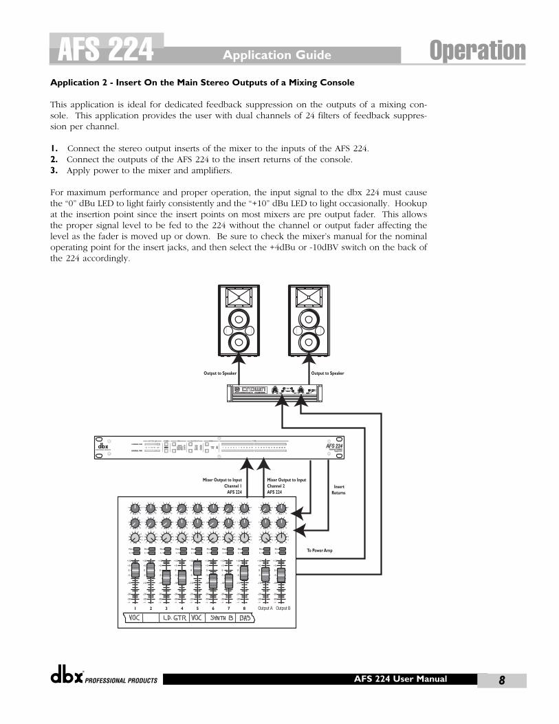
Application 2 - Insert On the Main Stereo Outputs of a Mixing Console
This application is ideal for dedicated feedback suppression on the outputs of a mixing con-sole. This application provides the user with dual channels of 24 filters of feedback suppres-sion per channel.
1. Connect the stereo output inserts of the mixer to the inputs of the AFS 224. 2. Connect the outputs of the AFS 224 to the insert returns of the console.3. Apply power to the mixer and amplifiers.
For maximum performance and proper operation, the input signal to the dbx 224 must causethe “0” dBu LED to light fairly consistently and the “+10” dBu LED to light occasionally. Hookupat the insertion point since the insert points on most mixers are pre output fader. This allowsthe proper signal level to be fed to the 224 without the channel or output fader affecting thelevel as the fader is moved up or down. Be sure to check the mixer’s manual for the nominaloperating point for the insert jacks, and then select the +4dBu or -10dBV switch on the back ofthe 224 accordingly.
Pan
Mute
-10
0
+5
+10
-20
-30-∞
-5
L / R
Mute
L / R
Mute
L / R
Mute
L / R
-5
-4
-3
-2-1 0 +1
+2
+3
+4
+5 Pan-5
-4
-3
-2-1 0 +1
+2
+3
+4
+5 Pan-5
-4
-3
-2-1 0 +1
+2
+3
+4
+5 Pan-5
-4
-3
-2-1 0 +1
+2
+3
+4
+5 Pan-5
-4
-3
-2-1 0 +1
+2
+3
+4
+5 Pan-5
-4
-3
-2-1 0 +1
+2
+3
+4
+5 Pan-5
-4
-3
-2-1 0 +1
+2
+3
+4
+5 Pan-5
-4
-3
-2-1 0 +1
+2
+3
+4
+5
1 2 3 4
-10
0
+5
+10
-20
-30-∞
-5
-10
0
+5
+10
-20
-30-∞
-5
-10
0
+5
+10
-20
-30-∞
-5
Mute
L / R
5
-10
0
+5
+10
-20
-30-∞
-5
Mute
L / R
6
-10
0
+5
+10
-20
-30-∞
-5
Mute
L / R
7
-10
0
+5
+10
-20
-30-∞
-5
Aux 10
2
4 6
8
10
Aux 20
2
4 6
8
10
Aux 10
2
4 6
8
10
Aux 20
2
4 6
8
10
Aux 10
2
4 6
8
10
Aux 20
2
4 6
8
10
Aux 10
2
4 6
8
10
Aux 20
2
4 6
8
10
Aux 10
2
4 6
8
10
Aux 20
2
4 6
8
10
Aux 10
2
4 6
8
10
Aux 20
2
4 6
8
10
Aux 10
2
4 6
8
10
Aux 20
2
4 6
8
10
Aux 10
2
4 6
8
10
Aux 20
2
4 6
8
10
Mute
L / R
8
-10
0
+5
+10
-20
-30-∞
-5
Pan-5
-4
-3
-2-1 0 +1
+2
+3
+4
+5 Pan-5
-4
-3
-2-1 0 +1
+2
+3
+4
+5
Mute
L / R
-10
0
+5
+10
-20
-30-∞
-5
Aux 10
2
4 6
8
10
Aux 20
2
4 6
8
10
Aux 10
2
4 6
8
10
Aux 20
2
4 6
8
10
Mute
L / R
-10
0
+5
+10
-20
-30-∞
-5
Output A Output B
Mixer Output to InputChannel 2AFS 224
Mixer Output to InputChannel 1
AFS 224
Output to SpeakerOutput to Speaker
Insert Returns
To Power Amp
Application Guide OperationAFS 224
8AFS 224 User Manual
Applications Guide
®
386 User Manual9
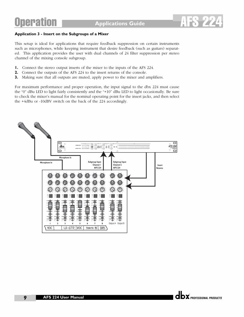
Operation AFS 224Application 3 - Insert on the Subgroups of a Mixer
This setup is ideal for applications that require feedback suppression on certain instrumentssuch as microphones, while keeping instrument that desire feedback (such as guitars) separat-ed. This application provides the user with dual channels of 24 filter suppression per stereochannel of the mixing console subgroup.
1. Connect the stereo output inserts of the mixer to the inputs of the AFS 224. 2. Connect the outputs of the AFS 224 to the insert returns of the console.3. Making sure that all outputs are muted, apply power to the mixer and amplifiers.
For maximum performance and proper operation, the input signal to the dbx 224 must causethe “0” dBu LED to light fairly consistently and the “+10” dBu LED to light occasionally. Be sureto check the mixer’s manual for the nominal operating point for the insert jacks, and then selectthe +4dBu or -10dBV switch on the back of the 224 accordingly.
Pan
Mute
-10
0
+5
+10
-20
-30-∞
-5
L / R
Mute
L / R
Mute
L / R
Mute
L / R
-5
-4
-3
-2-1 0 +1
+2
+3
+4
+5 Pan-5
-4
-3
-2-1 0 +1
+2
+3
+4
+5 Pan-5
-4
-3
-2-1 0 +1
+2
+3
+4
+5 Pan-5
-4
-3
-2-1 0 +1
+2
+3
+4
+5 Pan-5
-4
-3
-2-1 0 +1
+2
+3
+4
+5 Pan-5
-4
-3
-2-1 0 +1
+2
+3
+4
+5 Pan-5
-4
-3
-2-1 0 +1
+2
+3
+4
+5 Pan-5
-4
-3
-2-1 0 +1
+2
+3
+4
+5
1 2 3 4
-10
0
+5
+10
-20
-30-∞
-5
-10
0
+5
+10
-20
-30-∞
-5
-10
0
+5
+10
-20
-30-∞
-5
Mute
L / R
5
-10
0
+5
+10
-20
-30-∞
-5
Mute
L / R
6
-10
0
+5
+10
-20
-30-∞
-5
Mute
L / R
7
-10
0
+5
+10
-20
-30-∞
-5
Aux 10
2
4 6
8
10
Aux 20
2
4 6
8
10
Aux 10
2
4 6
8
10
Aux 20
2
4 6
8
10
Aux 10
2
4 6
8
10
Aux 20
2
4 6
8
10
Aux 10
2
4 6
8
10
Aux 20
2
4 6
8
10
Aux 10
2
4 6
8
10
Aux 20
2
4 6
8
10
Aux 10
2
4 6
8
10
Aux 20
2
4 6
8
10
Aux 10
2
4 6
8
10
Aux 20
2
4 6
8
10
Aux 10
2
4 6
8
10
Aux 20
2
4 6
8
10
Mute
L / R
8
-10
0
+5
+10
-20
-30-∞
-5
Pan-5
-4
-3
-2-1 0 +1
+2
+3
+4
+5 Pan-5
-4
-3
-2-1 0 +1
+2
+3
+4
+5
Mute
L / R
-10
0
+5
+10
-20
-30-∞
-5
Aux 10
2
4 6
8
10
Aux 20
2
4 6
8
10
Aux 10
2
4 6
8
10
Aux 20
2
4 6
8
10
Mute
L / R
-10
0
+5
+10
-20
-30-∞
-5
Output A Output B
Microphone In Subgroup InputChannel 2AFS 224
Subgroup InputChannel 1
AFS 224Insert
Returns
Microphone In
AFS 224 User Manual
®
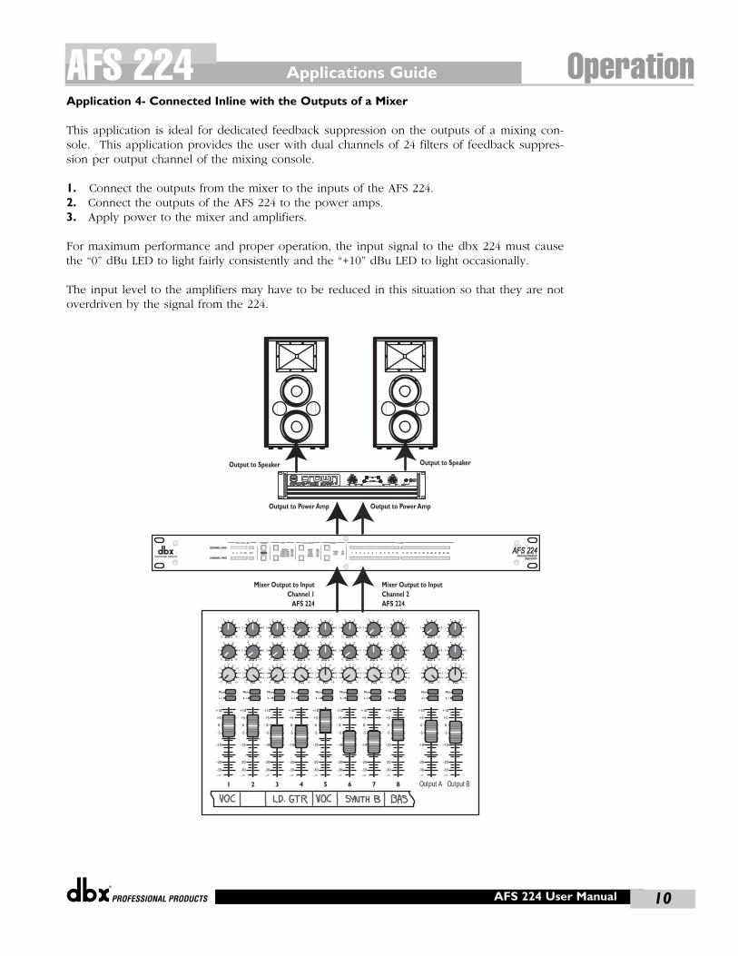
Application 4- Connected Inline with the Outputs of a Mixer
This application is ideal for dedicated feedback suppression on the outputs of a mixing con-sole. This application provides the user with dual channels of 24 filters of feedback suppres-sion per output channel of the mixing console.
1. Connect the outputs from the mixer to the inputs of the AFS 224. 2. Connect the outputs of the AFS 224 to the power amps.3. Apply power to the mixer and amplifiers.
For maximum performance and proper operation, the input signal to the dbx 224 must causethe “0” dBu LED to light fairly consistently and the “+10” dBu LED to light occasionally.
The input level to the amplifiers may have to be reduced in this situation so that they are notoverdriven by the signal from the 224.
Pan
Mute
-10
0
+5
+10
-20
-30-∞
-5
L / R
Mute
L / R
Mute
L / R
Mute
L / R
-5
-4
-3
-2-1 0 +1
+2
+3
+4
+5 Pan-5
-4
-3
-2-1 0 +1
+2
+3
+4
+5 Pan-5
-4
-3
-2-1 0 +1
+2
+3
+4
+5 Pan-5
-4
-3
-2-1 0 +1
+2
+3
+4
+5 Pan-5
-4
-3
-2-1 0 +1
+2
+3
+4
+5 Pan-5
-4
-3
-2-1 0 +1
+2
+3
+4
+5 Pan-5
-4
-3
-2-1 0 +1
+2
+3
+4
+5 Pan-5
-4
-3
-2-1 0 +1
+2
+3
+4
+5
1 2 3 4
-10
0
+5
+10
-20
-30-∞
-5
-10
0
+5
+10
-20
-30-∞
-5
-10
0
+5
+10
-20
-30-∞
-5
Mute
L / R
5
-10
0
+5
+10
-20
-30-∞
-5
Mute
L / R
6
-10
0
+5
+10
-20
-30-∞
-5
Mute
L / R
7
-10
0
+5
+10
-20
-30-∞
-5
Aux 10
2
4 6
8
10
Aux 20
2
4 6
8
10
Aux 10
2
4 6
8
10
Aux 20
2
4 6
8
10
Aux 10
2
4 6
8
10
Aux 20
2
4 6
8
10
Aux 10
2
4 6
8
10
Aux 20
2
4 6
8
10
Aux 10
2
4 6
8
10
Aux 20
2
4 6
8
10
Aux 10
2
4 6
8
10
Aux 20
2
4 6
8
10
Aux 10
2
4 6
8
10
Aux 20
2
4 6
8
10
Aux 10
2
4 6
8
10
Aux 20
2
4 6
8
10
Mute
L / R
8
-10
0
+5
+10
-20
-30-∞
-5
Pan-5
-4
-3
-2-1 0 +1
+2
+3
+4
+5 Pan-5
-4
-3
-2-1 0 +1
+2
+3
+4
+5
Mute
L / R
-10
0
+5
+10
-20
-30-∞
-5
Aux 10
2
4 6
8
10
Aux 20
2
4 6
8
10
Aux 10
2
4 6
8
10
Aux 20
2
4 6
8
10
Mute
L / R
-10
0
+5
+10
-20
-30-∞
-5
Output A Output B
Mixer Output to InputChannel 2AFS 224
Mixer Output to InputChannel 1
AFS 224
Output to Power Amp Output to Power Amp
Output to SpeakerOutput to Speaker
Applications Guide OperationAFS 224
10AFS 224 User Manual
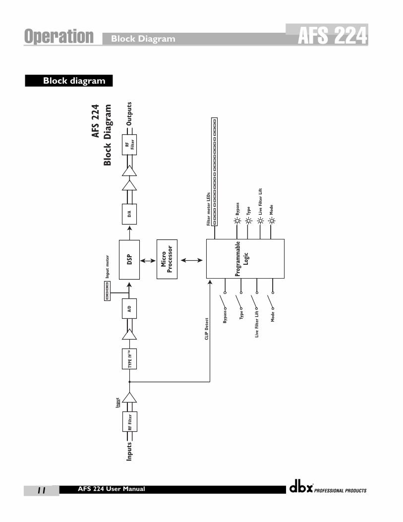
Block Diagram
®
386 User Manual11
Operation AFS 224
AFS
224
Bloc
k Dia
gram
TYPE
IV™
A/D
DSP
Mic
roPr
oces
sor
Prog
ram
mab
leLo
gic
CLIP
Det
ect
Bypa
ss
Type
Live
Filt
er L
ift
Mod
e
Bypa
ss
Type
Inpu
t m
eter
Inpu
t
D/A
RFFi
lter
Live
Filt
er L
ift
Mod
e
RF F
ilter
Out
puts
Inpu
ts
Filter
met
er L
EDs
Block diagram
AFS 224 User Manual
®
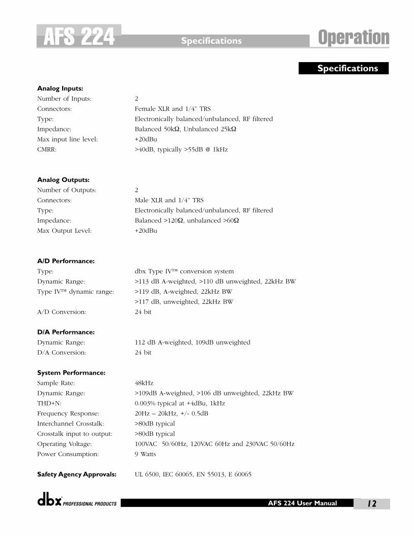
Analog Inputs:
Number of Inputs: 2
Connectors: Female XLR and 1/4” TRS
Type: Electronically balanced/unbalanced, RF filtered
Impedance: Balanced 50kΩ, Unbalanced 25kΩ
Max input line level: +20dBu
CMRR: >40dB, typically >55dB @ 1kHz
Analog Outputs:
Number of Outputs: 2
Connectors: Male XLR and 1/4” TRS
Type: Electronically balanced/unbalanced, RF filtered
Impedance: Balanced >120Ω, unbalanced >60Ω
Max Output Level: +20dBu
A/D Performance:
Type: dbx Type IV™ conversion system
Dynamic Range: >113 dB A-weighted, >110 dB unweighted, 22kHz BW
Type IV™ dynamic range: >119 dB, A-weighted, 22kHz BW
>117 dB, unweighted, 22kHz BW
A/D Conversion: 24 bit
D/A Performance:
Dynamic Range: 112 dB A-weighted, 109dB unweighted
D/A Conversion: 24 bit
System Performance:
Sample Rate: 48kHz
Dynamic Range: >109dB A-weighted, >106 dB unweighted, 22kHz BW
THD+N: 0.003% typical at +4dBu, 1kHz
Frequency Response: 20Hz – 20kHz, +/- 0.5dB
Interchannel Crosstalk: >80dB typical
Crosstalk input to output: >80dB typical
Operating Voltage: 100VAC 50/60Hz, 120VAC 60Hz and 230VAC 50/60Hz
Power Consumption: 9 Watts
Safety Agency Approvals: UL 6500, IEC 60065, EN 55013, E 60065
Specifications
Specifications OperationAFS 224
12AFS 224 User Manual

®
8760 South Sandy Pkwy.Sandy, Utah 84070
Phone: (801) 568-7660Fax: (801) 568-7662
Questions or comments E•mail us at: [email protected]
or visit our World Wide Web home page at:www.dbxpro.com
18-6398-A
A Harman International Company