aeronautical engineering - nasa · introduction this supplemental issue of aeronautical...
TRANSCRIPT

NASA/S P--1999-7037/S U P PL408
October 1999
AERONAUTICALENGINEERING
A CONTINUING BIBLIOGRAPHY WITH INDEXES
_i_iiiiiiiiiiiiiiiiiiiii
National Aeronautics andSpace AdministrationLangley Research Center
Scientific and TechnicalInformation Program Office
https://ntrs.nasa.gov/search.jsp?R=20000021481 2019-12-29T09:51:37+00:00Z
The NASA STI Program Office... in Profile
Since its founding, NASA has been dedicated
to the advancement of aeronautics and spacescience. The NASA Scientific and Technical
Information (STI) Program Office plays a key
part in helping NASA maintain this importantrole.
The NASA STI Program Office is operated by
Langley Research Center, the lead center forNASA's scientific and technical information.
The NASA STI Program Office provides access
to the NASA STI Database, the largest collection
of aeronautical and space science STI in the
world. The Program Office is also NASA's
institutional mechanism for disseminating the
results of its research and development activities.
These results are published by NASA in the
NASA STI Report Series, which includes the
following report types:
TECHNICAL PUBLICATION. Reports of
completed research or a major significant
phase of research that present the results of
NASA programs and include extensive data or
theoretical analysis. Includes compilations of
significant scientific and technical data and
information deemed to be of continuing
reference value. NASA's counterpart of peer-
reviewed formal professional papers but has
less stringent limitations on manuscript length
and extent of graphic presentations.
TECHNICAL MEMORANDUM. Scientific
and technical findings that are preliminary or
of specialized interest, e.g., quick release
reports, working papers, and bibliographiesthat contain minimal annotation. Does not
contain extensive analysis.
CONTRACTOR REPORT. Scientific and
technical findings by NASA-sponsored
contractors and grantees.
CONFERENCE PUBLICATION. Collected
papers from scientific and technical
conferences, symposia, seminars, or other
meetings sponsored or cosponsored by NASA.
SPECIAL PUBLICATION. Scientific,
technical, or historical information from
NASA programs, projects, and missions,
often concerned with subjects having
substantial public interest.
TECHNICAL TRANSLATION.
English-language translations of foreign
scientific and technical material pertinent toNASA's mission.
Specialized services that complement the STI
Program Office's diverse offerings include
creating custom thesauri, building customized
databases, organizing and publishing research
results.., even providing videos.
For more information about the NASA STI
Program Office, see the following:
• Access the NASA STI Program Home Page at
http://www.sti.nasa.gov
• E-mail your question via the Internet to
• Fax your question to the NASA STI Help Deskat (301) 621-0134
• Telephone the NASA STI Help Desk at
(301) 621-0390
Write to:
NASA STI Help Desk
NASA Center for AeroSpace Information7121 Standard Drive
Hanover, MD 21076-1320
Introduction
This supplemental issue of Aeronautical Engineering, A Continuing Bibliography with Indexes
(NASA/SP--1999-7037) lists reports, articles, and other documents recently announced in theNASA STI Database.
The coverage includes documents on the engineering and theoretical aspects of design, construction,
evaluation, testing, operation, and performance of aircraft (including aircraft engines) and associ-
ated components, equipment, and systems. It also includes research and development in aerodynam-
ics, aeronautics, and ground support equipment for aeronautical vehicles.
Each entry in the publication consists of a standard bibliographic citation accompanied, in most
cases, by an abstract.
The NASA CASI price code table, addresses of organizations, and document availability informa-
tion are included before the abstract section.
Two indexes--subject and author are included after the abstract section.

SCAN Goes Electronic!If you have electronic mail or if you can access the Internet, you can view biweekly issues of SCAN
from your desktop absolutely free!
Electronic SCAN takes advantage of computer technology to inform you of the latest worldwide,
aerospace-related, scientific and technical information that has been published.
No more waiting while the paper copy is printed and mailed to you. You can view Electronic SCAN
the same day it is released--up to 191 topics to browse at your leisure. When you locate a publication
of interest, you can print the announcement. You can also go back to the Electronic SCAN home page
and follow the ordering instructions to quickly receive the full document.
Start your access to Electronic SCAN today. Over 1,000 announcements of new reports, books, con-
ference proceedings, journal articles...and more--available to your computer every two weeks.
For Internet access to E-SCAN, use any of the
following addresses:
http://www.stLnasa,gov
ftp.sti.nasa.gov
gopher.sti.nasa.gov
To receive a free subscription, send e-mail for complete information about the service first. Enter
[email protected] on the address line. Leave the subject and message areas blank and send. You
will receive a reply in minutes.
Then simply determine the SCAN topics you wish to receive and send a second e-mail to
[email protected]. Leave the subject line blank and enter a subscribe command, denoting which
topic you want and your name in the message area, formatted as follows:
Subscribe SCAN-02-01 Jane Doe
For additional information, e-mail a message to [email protected].
Phone: (301) 621-0390
Fax: (301) 621-0134
Write: NASA STI Help Desk
NASA Center for AeroSpace Information7121 Standard Drive
Hanover, MD 21076-1320
Looking just for Aerospace Medicine and Biology reports?
Although hard copy distribution has been discontinued, you can
still receive these vital announcements through your E-SCAN
subscription. Just Subscribe SCAN-AEROMED Jane Doe
in the message area of your e-mail to [email protected].
..........._:iiii:;:_
Table of Contents
Records are arranged in categories 1 through 19, the first nine coming from the Aeronautics division
of STAR, followed by the remaining division titles. Selecting a category will link you to the collection
of records cited in this issue pertaining to that category.
01 Aeronautics (General) 1
Includes general research topics related to manned and unmanned aircraft and the problems
of flight within the Earth's atmosphere. Also includes manufacturing, maintenance, and
repair of aircraft.
02 Aerodynamics 2
Includes aerodynamics of flight vehicles, test bodies, airframe components and
combinations, wings, and control surfaces. Also includes aerodynamics of rotors, stators,
fans and other elements of turbomachinery.
03 Air Transportation and Safety 6
Includes passenger and cargo air transport operations; aircraft ground operations; flight
safety and hazards; and aircraft accidents.
04 Aircraft Communications and Navigation 15
Includes all modes of communication with and between aircraft; air navigation systems
(satellite and ground based); and air traffic control.
05 Aircraft Design, Testing and Performance 17
Includes all stages of design of aircraft and aircraft structures and systems. Also includes
aircraft testing, performance, and evaluation, and aircraft and flight simulation technology.
06 Avionics and Aircraft Instrumentation 27
Includes all avionics systems, cockpit and cabin display devices; and flight instrumentsintended for use in aircraft.
07 Aircraft Propulsion and Power 28
Includes prime propulsion systems and systems components, e.g., gas turbine engines and
compressors; and onboard auxiliary power plants for aircraft.
08 Aircraft Stability and Contro[ 38
Includes flight dynamics, aircraft handling qualities; piloting; flight controls; and autopilots.
09 Research and Support Facilities (Air) 41
Includes airports, runways, hangars, and aircraft repair and overhaul facilities; wind tunnels,
water tunnels, and shock tubes; flight simulators; and aircraft engine test stands. Also
includes airport ground equipment and systems.
I0
11
12
13
14
I5
16
17
18
19
Astronautics 43
Includes astronautics (general); astrodynamics; ground support systems and facilities
(space); launch vehicles and space vehicles; space transportation; space communications,
spacecraft communications, command and tracking; spacecraft design, testing and perfor-
mance; spacecraft instrumentation and astrionics; and spacecraft propulsion and power.
Chemistry and @aterials 48Includes chemistry and materials (general); composite materials; inorganic, organic, and
physical chemistry; metals and metallic materials; nonmetallic materials; propellants and
fuels; and space processing.
Engineering 49
Includes engineering (general); communications and radar; electronics and electrical engi-
neering; fluid mechanics and thermodynamics; instrumentation and photography; lasers and
masers; mechanical engineering; quality assurance and reliability; and structural mechanics.
Geosciences 55
Includes geosciences (general); earth resources and remote sensing; energy production and
conversion; environment pollution; geophysics; meteorology and climatology; and ocean-
ography.
Life Sciences 56
Includes life sciences (general); aerospace medicine; behavioral sciences; man/system
technology and life support; and exobiology.
@athematicN and Computer Sciences 57Includes mathematical and computer sciences (general); computer operations and hardware;
computer programming and software; computer systems; cybernetics, artificial intelligence
and robotics; numerical analysis; statistics and probability; systems analysis and operations
research; and theoretical mathematics.
Physics 58Includes physics (general); acoustics; atomic and molecular physics; nuclear physics; optics;
plasma physics; solid-state physics; and physics of elementary particles and fields.
SociN Sciences N.A°
Includes social sciences (general); administration and management; documentation and
information science; economics and cost analysis; law, political science and space policy;
and technology utilization and surface transportation.
Space Sciences N.A.Includes space sciences (general); astronomy; astrophysics; lunar and planetary science and
exploration; solar physics; and space radiation.
Genera[ NoAo
ndexesTwo indexes are available. You may use the find command under the tools menu while viewing the
PDF file for direct match searching on any text string. You may also view the indexes provided, for
searching on NASA Thesaurus subject terms and author names.
Subject Term Index ST-1Author index PA-1
Selecting an index above will link you to that comprehensive listing.
Document AvaimabiiitySelect Avaima bility mnfo for important information about NASA Scientific and Technical Infor-
mation (STI) Program Office products and services, including registration with the NASA Center
for AeroSpace Information (CASI) for access to the NASA CASI TRS (Technical Report Server),
and availability and pricing information for cited documents.

The New NASA Video
Catalog is
To order your_
@
call the NASA STI Help Desk at
(301) 621-0390,
fax to
(301) 621-0134,
e-mail to
or visit the NASA STI Program
homepage at
http ://www. st i.nasa.gov
(Select STI Program Bibliographic Announcements)
Explore the Universe]
Document AvailabiEity nformation
The mission of the NASA Scientific and Technical (STI) Program Office is to quickly, efficiently,
and cost-effectively provide the NASA community with desktop access to STI produced by NASA
and the world's aerospace industry and academia. In addition, we will provide the aerospace
industry, academia, and the taxpayer access to the intellectual scientific and technical output and
achievements of NASA.
Eligibility and Registration for NASA STI Products and Services
The NASA STI Program offers a wide variety of products and services to achieve its mission. Your
affiliation with NASA determines the level and type of services provided by the NASA STI
Program. To assure that appropriate level of services are provided, NASA STI users are requested to
register at the NASA Center for AeroSpace Information (CASI). Please contact NASA CASI in one
of the following ways:
E-mail:
Fax:
Phone:
Mail:
help@ sti.nasa.gov
301-621-0134
301-621-0390
ATTN: Registration Services
NASA Center for AeroSpace Information
7121 Standard Drive
Hanover, MD 21076-1320
Limited Reproducibility
In the database citations, a note of limited reproducibility appears if there are factors affecting the
reproducibility of more than 20 percent of the document. These factors include faint or broken type,
color photographs, black and white photographs, foldouts, dot matrix print, or some other factor that
limits the reproducibility of the document. This notation also appears on the microfiche header.
NASA Patents and Patent Applications
Patents and patent applications owned by NASA are announced in the STI Database. Printed copies
of patents (which are not microfiched) are available for purchase from the U.S. Patent and
Trademark Office.
When ordering patents, the U.S. Patent Number should be used, and payment must be remitted in
advance, by money order or check payable to the Commissioner of Patents and Trademarks. Prepaid
purchase coupons for ordering are also available from the U.S. Patent and Trademark Office.

NASA patent application specifications are sold in both paper copy and microfiche by the NASA
Center for AeroSpace Information (CASI). The document ID number should be used in ordering
either paper copy or microfiche from CASI.
The patents and patent applications announced in the STI Database are owned by NASA and are
available for royalty-free licensing. Requests for licensing terms and further information should be
addressed to:
National Aeronautics and Space Administration
Associate General Counsel for Intellectual Property
Code GP
Washington, DC 20546-0001
Sources for Documents
One or more sources from which a document announced in the STI Database is available to the
public is ordinarily given on the last line of the citation. The most commonly indicated sources and
their acronyms or abbreviations are listed below, with an Addresses of Organizations list near the
back of this section. If the publication is available from a source other than those listed, the publisher
and his address will be displayed on the availability line or in combination with the corporate source.
Avail:
Avail:
Avail:
Avail:
NASA CASI. Sold by the NASA Center for AeroSpace Information. Prices for hard copy
(HC) and microfiche (MF) are indicated by a price code following the letters HC or MF in
the citation. Current values are given in the NASA CASI Price Code Table near the end ofthis section.
Note on Ordering Documents: When ordering publications from NASA CASI, use the document ID numberor other report number. It is also advisable to cite the title and other bibliographic identification.
SOD (or GPO). Sold by the Superintendent of Documents, U.S. Government Printing
Office, in hard copy.
BLL (formerly NLL): British Library Lending Division, Boston Spa, Wetherby, Yorkshire,
England. Photocopies available from this organization at the price shown. (If none is given,
inquiry should be addressed to the BLL.)
DOE Depository Libraries. Organizations in U.S. cities and abroad that maintain
collections of Department of Energy reports, usually in microfiche form, are listed in
Energy Research Abstracts. Services available from the DOE and its depositories are
described in a booklet, DOE Technical Information Center--Its Functions and Services
(TID-4660), which may be obtained without charge from the DOE Technical InformationCenter.
Avail:
Avail:
ESDU. Pricing information on specific data, computer programs, and details on ESDU
International topic categories can be obtained from ESDU International.
Fachinformationszentrum Karlsruhe. Gesellschaft fiir wissenschaftlich-technische
Information mbH 76344 Eggenstein-Leopoldshafen, Germany.

Avail:
Avail:
Avail:
Avail:
Avail:
Avail:
Avail:
Avail:
HMSO. Publications of Her Majesty's Stationery Office are sold in the U.S. by Pendragon
House, Inc. (PHI), Redwood City, CA. The U.S. price (including a service and mailing
charge) is given, or a conversion table may be obtained from PHI.
Issuing Activity, or Corporate Author, or no indication of availability. Inquiries as to the
availability of these documents should be addressed to the organization shown in the
citation as the corporate author of the document.
NASA Public Document Rooms. Documents so indicated may be examined at or purchased
from the National Aeronautics and Space Administration (JBD-4), Public Documents
Room (Room 1H23), Washington, DC 20546-0001, or public document rooms located at
NASA installations, and the NASA Pasadena Office at the Jet Propulsion Laboratory.
NTIS. Sold by the National Technical Information Service. Initially distributed microfiche
under the NTIS SRIM (Selected Research in Microfiche) are available. For information
concerning this service, consult the NTIS Subscription Section, Springfield, VA 22161.
Univ. Microfilms. Documents so indicated are dissertations selected from Dissertation
Abstracts and are sold by University Microfilms as xerographic copy (HC) and microfilm.
All requests should cite the author and the Order Number as they appear in the citation.
US Patent and Trademark Office. Sold by Commissioner of Patents and Trademarks, U.S.
Patent and Trademark Office, at the standard price of $1.50 each, postage free.
(US Sales Only). These foreign documents are available to users within the United States
from the National Technical Information Service (NTIS). They are available to users
outside the United States through the International Nuclear Information Service (IN1S)
representative in their country, or by applying directly to the issuing organization.
USGS. Originals of many reports from the U.S. Geological Survey, which may contain
color illustrations, or otherwise may not have the quality of illustrations preserved in the
microfiche or facsimile reproduction, may be examined by the public at the libraries of the
USGS field offices whose addresses are listed on the Addresses of Organizations page. The
libraries may be queried concerning the availability of specific documents and the possible
utilization of local copying services, such as color reproduction.

Addresses of Organizations
British Library Lending Division
Boston Spa, Wetherby, Yorkshire
England
Commissioner of Patents and TrademarksU.S. Patent and Trademark Office
Washington, DC 20231
Department of EnergyTechnical Information Center
EO. Box 62
Oak Ridge, TN 37830
European Space Agency-Information Retrieval Service ESRIN
Via Galileo Galilei
00044 Frascati (Rome) Italy
ESDU International
27 Corsham Street
London
N1 6UA
England
Fachinformationszentrum Karlsruhe
Gesellschaft ffir wissenschaftlich-technische
Information mbH
76344 Eggenstein-Leopoldshafen, Germany
Her Majesty's Stationery Office
RO. Box 569, S.E. 1
London, England
NASA Center for AeroSpace Information7121 Standard Drive
Hanover, MD 21076-1320
(NASA STI Lead Center)
National Aeronautics and Space Administration
Scientific and Technical Information Program Office
Langley Research Center- MS 157
Hampton, VA 23681
National Technical Information Service
5285 Port Royal Road
Springfield, VA 22161
Pendragon House, Inc.
899 Broadway Avenue
Redwood City, CA 94063
Superintendent of Documents
U.S. Government Printing Office
Washington, DC 20402
University Microfilms
A Xerox Company300 North Zeeb Road
Ann Arbor, MI 48106
University Microfilms, Ltd.
Tylers Green
London, England
U.S. Geological Survey Library National CenterMS 95O
12201 Sunrise Valley Drive
Reston, VA 22092
U.S. Geological Survey Library2255 North Gemini Drive
Flagstaff, AZ 86001
U.S. Geological Survey345 Middlefield Road
Menlo Park, CA 94025
U.S. Geological Survey LibraryBox 25046
Denver Federal Center, MS914
Denver, CO 80225
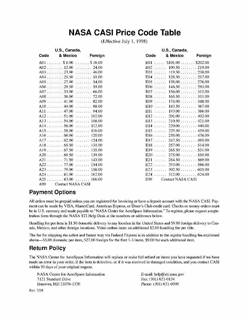
NASA CASI Price Code Table(Effective July 1, 1998)
U.S., Canada,
Code & Mexico Foreign
A01 ....... $ 8.00 ....... $16.00A02 ........ 12.00 ........ 24.00
A03 ........ 23.00 ........ 46.00
A04 ........ 25.50 ........ 51.00
A05 ........ 27.00 ........ 54.00
A06 ........ 29.50 ........ 59.00
A07 ........ 33.00 ........ 66.00
A08 ........ 36.00 ........ 72.00
A09 ........ 41.00 ........ 82.00
A10 ........ 44.00 ........ 88.00
All ........ 47.00 ........ 94.00
A12 ........ 51.00 ....... 102.00
A13 ........ 54.00 ....... 108.00
A14 ........ 56.00 ....... 112.00
A15 ........ 58.00 ....... 116.00
A16 ........ 60.00 ....... 120.00
A17 ........ 62.00 ....... 124.00
A18 ........ 65.50 ....... 131.00
A19 ........ 67.50 ....... 135.00
A20 ........ 69.50 ....... 139.00
A21 ........ 71.50 ....... 143.00A22 ........ 77.00 ....... 154.00
A23 ........ 79.00 ....... 158.00
A24 ........ 81.00 ....... 162.00
A25 ........ 83.00 ....... 166.00
A99 Contact NASA CASI
Payment Options
U.S., Canada,
Code & Mexico Foreign
E01 ..... $101.00 ....... $202.00E02 ...... 109.50 ........ 219.00
E03 ...... 119.50 ........ 238.00
E04 ...... 128.50 ........ 257.00
E05 ...... 138.00 ........ 276.00
E06 ...... 146.50 ........ 293.00
E07 ...... 156.00 ........ 312.00
E08 ...... 165.50 ........ 331.00
E09 ...... 174.00 ........ 348.00
El0 ...... 183.50 ........ 367.00
Ell ...... 193.00 ........ 386.00
El2 ...... 201.00 ........ 402.00
El3 ...... 210.50 ........ 421.00
El4 ...... 220.00 ........ 440.00
El5 ...... 229.50 ........ 459.00
El6 ...... 238.00 ........ 476.00
El7 ...... 247.50 ........ 495.00
El8 ...... 257.00 ........ 514.00
El9 ...... 265.50 ........ 531.00
E20 ...... 275.00 ........ 550.00
E21 ...... 284.50 ........ 569.00E22 ...... 293.00 ........ 586.00
E23 ...... 302.50 ........ 605.00
E24 ...... 312.00 ........ 624.00
E99 Contact NASA CASI
All orders must be prepaid unless you are registered for invoicing or have a deposit account with the NASA CASI. Pay-
ment can be made by VISA, MasterCard, American Express, or Diner's Club credit card. Checks or money orders must
be in U.S. currency and made payable to "NASA Center for AeroSpace Information." To register, please request a regis-
tration form through the NASA STI Help Desk at the numbers or addresses below.
Handling fee per item is $1.50 domestic delivery to any location in the United States and $9.00 foreign delivery to Can-
ada, Mexico, and other foreign locations. Video orders incur an additional $2.00 handling fee per title.
The fee for shipping the safest and fastest way via Federal Express is in addition to the regular handling fee explained
above--S5.00 domestic per item, $27.00 foreign for the first 1-3 items, $9.00 for each additional item.
Return Policy
The NASA Center for AeroSpace Information will replace or make full refund on items you have requested if we have
made an error in your order, if the item is defective, or if it was received in damaged condition, and you contact CASI
within 30 days of your original request.
NASA Center for AeroSpace Information E-mail: [email protected]
7121 Standard Drive Fax: (301)621-0134
Hanover, MD 21076-1320 Phone: (301) 621-0390
Rev. 7/98
Federal Depository Library Program
In order to provide the general public with greater access to U.S. Government publications, Congress
established the Federal Depository Library Program under the Government Printing Office (GPO),
with 53 regional depositories responsible for permanent retention of material, inter-library loan, and
reference services. At least one copy of nearly every NASA and NASA-sponsored publication,
either in printed or microfiche format, is received and retained by the 53 regional depositories. A list
of the Federal Regional Depository Libraries, arranged alphabetically by state, appears at the very
end of this section. These libraries are not sales outlets. A local library can contact a regional
depository to help locate specific reports, or direct contact may be made by an individual.
Public Collection of NASA Documents
An extensive collection of NASA and NASA-sponsored publications is maintained by the British
Library Lending Division, Boston Spa, Wetherby, Yorkshire, England for public access. The British
Library Lending Division also has available many of the non-NASA publications cited in the STI
Database. European requesters may purchase facsimile copy or microfiche of NASA and
NASA-sponsored documents FIZ-Fachinformation Karlsruhe-Bibliographic Service, D-76344
Eggenstein-Leopoldshafen, Germany and TIB-Technische Informationsbibliothek, RO. Box
60 80, D-30080 Hannover, Germany.
Submitting Documents
All users of this abstract service are urged to forward reports to be considered for announcement in
the STI Database. This will aid NASA in its efforts to provide the fullest possible coverage of all
scientific and technical publications that might support aeronautics and space research and
development. If you have prepared relevant reports (other than those you will transmit to NASA,
DOD, or DOE through the usual contract- or grant-reporting channels), please send them for
consideration to:
ATTN: Acquisitions Specialist
NASA Center for AeroSpace Information
7121 Standard Drive
Hanover, MD 21076-1320.
Reprints of journal articles, book chapters, and conference papers are also welcome.
You may specify a particular source to be included in a report announcement if you wish; otherwise
the report will be placed on a public sale at the NASA Center for AeroSpace Information.
Copyrighted publications will be announced but not distributed or sold.

Federal Regional Depository Libraries
ALABAMAAUBURN UNIV. AT MONTGOMERY
LIBRARY
Documents Dept.
7300 University Dr.
Montgomery, AL 36117-3596
(205) 244-3650 Fax: (205) 244-0678
UNIV. OF ALABAMA
Amelia Gayle Gorgas LibraryGovt. Documents
P.O. Box 870266
Tuscaloosa, AL 35487-0266
(205) 348-6046 Fax: (205) 348-0760
ARIZONADEPT. OF LIBRARY, ARCHIVES,
AND PUBLIC RECORDS
Research Division
Third Floor, State Capitol
1700 West WashingtonPhoenix, AZ 85007
(602) 542-3701 Fax: (602) 542-4400
ARKANSASARKANSAS STATE LIBRARY
State Library Service SectionDocuments Service Section
One Capitol Mall
Little Rock, AR 72201-1014
(501) 682-2053 Fax: (501) 682-1529
CALIFORNIACALIFORNIA STATE LIBRARYGovt. Publications Section
P.O. Box 942837 - 914 Capitol Mall
Sacramento, CA 94337-0091
(916) 654-0069 Fax: (916) 654-0241
COLORADOUNIV. OF COLORADO - BOULDER
Libraries - Govt. Publications
Campus Box 184Boulder, CO 80309-0184
(303) 492-8834 Fax: (303) 492-1881
DENVER PUBLIC LIBRARY
Govt. Publications Dept. BSG
1357 BroadwayDenver, CO 80203-2165
(303) 640-8846 Fax: (303) 640-8817
CONNECTICUTCONNECTICUT STATE LIBRARY
231 Capitol Avenue
Hartford, CT 06106
(203) 566-4971 Fax: (203) 566-3322
FLORIDAUNIV. OF FLORIDA LIBRARIES
Documents Dept.240 Library West
Gainesville, FL 32611-2048
(904) 392-0366 Fax: (904) 392-7251
GEORGIAUNIV. OF GEORGIA LIBRARIES
Govt. Documents Dept.Jackson Street
Athens, GA 30602-1645
(706) 542-8949 Fax: (706) 542-4144
HAWAIIUNIV. OF HAWAII
Hamilton LibraryGovt. Documents Collection
2550 The Mall
Honolulu, HI 96822
(808) 948-8230 Fax: (808) 956-5968
IDAHOUNIV. OF IDAHO LIBRARYDocuments Section
Rayburn Street
Moscow, ID 83844-2353
(208) 885-6344 Fax: (208) 885-6817
ILLINOISILLINOIS STATE LIBRARY
Federal Documents Dept.300 South Second Street
Springfield, IL 62701-1796
(217) 782-7596 Fax: (217) 782-6437
INDIANAINDIANA STATE LIBRARY
Serials/Documents Section
140 North Senate Avenue
Indianapolis, IN 46204-2296
(317) 232-3679 Fax: (317) 232-3728
IOWAUNIV. OF IOWA LIBRARIES
Govt. Publications
Washington & Madison Streets
Iowa City, IA 52242-1166
(319) 335-5926 Fax: (319) 335-5900
KANSASUNIV. OF KANSAS
Govt. Documents & Maps Library6001 Malott Hall
Lawrence, KS 66045-2800
(913) 864-4660 Fax: (913) 864-3855
KENTUCKYUNIV. OF KENTUCKY
King Library South
Govt. Publications/Maps Dept.Patterson Drive
Lexington, KY 40506-0039
(606) 257-3139 Fax: (606) 257-3139
LOUISIANALOUISIANA STATE UNIV.
Middleton Library
Govt. Documents Dept.
Baton Rouge, LA 70803-3312
(504) 388-2570 Fax: (504) 388-6992
LOUISIANA TECHNICAL UNIV.
Prescott Memorial Library
Govt. Documents Dept.
Ruston, LA 71272-0046
(318) 257-4962 Fax: (318) 257-2447
MAINEUNIV. OF MAINE
Raymond H. Fogler Library
Govt. Documents Dept.Orono, M E 04469-5729
(207) 581-1673 Fax: (207) 581-1653
MARYLANDUNIV. OF MARYLAND - COLLEGEPARK
McKeldin LibraryGovt. Documents/Maps Unit
College Park, MD 20742
(301) 405-9165 Fax: (301) 314-9416
MASSACHUSE'I-I'SBOSTON PUBLIC LIBRARYGovt. Documents
666 Boylston Street
Boston, MA 02117-0286
(617) 536-5400, ext. 226
Fax: (617) 536-7758
MICHIGANDETROIT PUBLIC LIBRARY
5201 Woodward Avenue
Detroit, MI 48202-4093
(313) 833-1025 Fax: (313) 833-0156
LIBRARY OF MICHIGAN
Govt. Documents Unit
P.O. Box 30007
717 West Allegan Street
Lansing, MI 48909
(517) 373-1300 Fax: (517) 373-3381
MINNESOTAUNIV. OF MINNESOTA
Govt. Publications
409 Wilson Library309 19th Avenue South
Minneapolis, MN 55455
(612) 624-5073 Fax: (612) 626-9353
MISSISSIPPIUNIV. OF MISSISSIPPI
J.D. Williams Library
106 Old Gym Bldg.
University, MS 38677
(601) 232-5857 Fax: (601) 232-7465
MISSOURIUNIV. OF MISSOURI - COLUMBIA
106B Ellis LibraryGovt. Documents Sect.
Columbia, MO 65201-5149
(314) 882-6733 Fax: (314) 882-8044
MONTANAUNIV. OF MONTANA
Mansfield LibraryDocuments Division
Missoula, MT 59812-1195
(406) 243-6700 Fax: (406) 243-2060
NEBRASKAUNIV. OF NEBRASKA - LINCOLN
D.L. Love Memorial Library
Lincoln, NE 68588-0410
(402) 472-2562 Fax: (402) 472-5131
NEVADATHE UNIV. OF NEVADA
LIBRARIES
Business and Govt. InformationCenter
Reno, NV 89557-0044
(702) 784-6579 Fax: (702) 784-1751
NEW JERSEYNEWARK PUBLIC LIBRARY
Science Div. - Public Access
P.O. Box 630
Five Washington StreetNewark, NJ 07101-7812
(201) 733-7782 Fax: (201) 733-5648
NEW MEXICOUNIV. OF NEW MEXICO
General Library
Govt. Information Dept.
Albuquerque, NM 87131-1466
(505) 277-5441 Fax: (505) 277-6019
NEW MEXICO STATE LIBRARY
325 Don Gaspar Avenue
Santa Fe, NM 87503
(505) 827-3824 Fax: (505) 827-3888
NEW YORKNEW YORK STATE LIBRARY
Cultural Education Center
Documents/Gift & Exchange SectionEmpire State Plaza
Albany, NY 12230-0001
(518) 474-5355 Fax: (518) 474-5786
NORTH CAROLINAUNIV. OF NORTH CAROLINA -
CHAPEL HILL
Walter Royal Davis Library
CB 3912, Reference Dept.Chapel Hill, NO 27514-8890
(919) 962-1151 Fax: (919) 962-4451
NORTH DAKOTANORTH DAKOTA STATE UNIV. LIB.
Documents
P.O. Box 5599
Fargo, N D 58105-5599
(701) 237-8886 Fax: (701) 237-7138
UNIV. OF NORTH DAKOTA
Chester Fritz Library
University StationP.O. Box 9000 - Centennial and
University Avenue
Grand Forks, ND 58202-9000
(701) 777-4632 Fax: (701) 777-3319
OHIOSTATE LIBRARY OF OHIO
Documents Dept.65 South Front Street
Columbus, OH 43215-4163
(614) 644-7051 Fax: (614) 752-9178
OKLAHOMAOKLAHOMA DEPT. OF LIBRARIES
U.S. Govt. Information Division
200 Northeast 18th Street
Oklahoma City, OK 73105-3298
(405) 521-2502, ext. 253
Fax: (405) 525-7804
OKLAHOMA STATE UNIV.
Edmon Low LibraryStillwater, OK 74078-0375
(405) 744-6546 Fax: (405) 744-5183
OREGONPORTLAND STATE UNIV.
Branford P. Millar Library934 Southwest Harrison
Portland, OR 97207-1151
(503) 725-4123 Fax: (503) 725-4524
PENNSYLVANIASTATE LIBRARY OF PENN,
Govt. Publications Section
116 Walnut & Commonwealth Ave.
Harrisburg, PA 17105-1601
(717) 787-3752 Fax: (717) 783-2070
SOUTH CAROLINACLEMSON UNIV.
Robert Muldrow Cooper LibraryPublic Documents Unit
P.O. Box 343001
Clemson, SO 29634-3001
(803) 656-5174 Fax: (803) 656-3025
UNIV. OF SOUTH CAROLINA
Thomas Cooper LibraryGreen and Sumter Streets
Columbia, SO 29208
(803) 777-4841 Fax: (803) 777-9503
TENNESSEEUNIV. OF MEMPHIS LIBRARIES
Govt. Publications Dept.
Memphis, TN 38152-0001
(901) 678-2206 Fax: (901) 678-2511
TEXASTEXAS STATE LIBRARYUnited States Documents
P.O. Box 12927- 1201 Brazos
Austin, TX 78701-0001
(512) 463-5455 Fax: (512) 463-5436
TEXAS TECH. UNIV. LIBRARIES
Documents Dept.
Lubbock, TX 79409-0002
(806) 742-2282 Fax: (806) 742-1920
UTAHUTAH STATE UNIV.
Merrill Library Documents Dept.
Logan, UT 84322-3000
(801) 797-2678 Fax: (801) 797-2677
VIRGINIAUNIV. OF VIRGINIA
Alderman LibraryGovt. Documents
University Ave. & McCormick Rd.
Charlottesville, VA 22903-2498
(804) 824-3133 Fax: (804) 924-4337
WASHINGTONWASHINGTON STATE LIBRARY
Govt. Publications
P.O. Box 42478
16th and Water Streets
Olympia, WA 98504-2478
(206) 753-4027 Fax: (206) 586-7575
WEST VIRGINIAWEST VIRGINIA UNIV. LIBRARYGovt. Documents Section
P.O. Box 6069 - 1549 University Ave.
Morgantown, WV 26506-6069
(304) 293-3051 Fax: (304) 293-6638
WISCONSINST. HIST. SOC. OF WISCONSINLIBRARY
Govt. Publication Section
816 State Street
Madison, Wl 53706
(608) 264-6525 Fax: (608) 264-6520
MILWAUKEE PUBLIC LIBRARYDocuments Division
814 West Wisconsin Avenue
Milwaukee, Wl 53233
(414) 286-3073 Fax: (414) 286-8074

Typical Report Citation and Abstract
@ i_9970001_26 NASA Langley Research Center, Hampton, VA USA
0 Water "I'm_nelF_ow Vis_alization St_dy "I'hro_gh P_ststaH of 12 Novel Planform Shapes
O Gatlin, Gregory M., NASA Langley Research Center, USA Neuhart, Dan H., Lockheed Engineering and Sciences Co., USA;
Mar. 1996; 130p; In EnglishContract(s)/Grant(s): RTOP 505-68-70-04
O Report No(s): NASA-TM-4663; NAS 1.15:4663; L-17418; No Copyright; Avail: CASI; A07, Hardcopy; A02, Microfiche
@ To determine the flow field characteristics of 12 planform geometries, a flow visualization investigation was conducted
in the Langley 16- by 24-Inch Water Tunnel. Concepts studied included flat plate representations of diamond wings, twin
bodies, double wings, cutout wing configurations, and serrated forebodies. The off-surface flow patterns were identified by
injecting colored dyes from the model surface into the free-stream flow. These dyes generally were injected so that the local-
ized vortical flow patterns were visualized. Photographs were obtained for angles of attack ranging from 10' to 50', and all
investigations were conducted at a test section speed of 0.25 ft per sec. Results from the investigation indicate that the forma-
tion of strong vortices on highly swept forebodies can improve poststail lift characteristics; however, the asymmetric bursting
of these vortices could produce substantial control problems. A wing cutout was found to significantly alter the position of
the forebody vortex on the wing by shifting the vortex inboard. Serrated forebodies were fonnd to effectively generate multi-
ple vortices over the configuration. Vortices from 65' swept forebody serrations tended to roll together, while vortices from
40' swept serrations were more effective in generating additional lift caused by their more independent nature.O Author
0 Water Tunnel Tests; Flow Visualization; Flow Distribution; Free Flow; Planforms; Wing Profiles; Aerodynamic
Configurations
Key
1. Document ID Number; Corporate Source2. Title
3. Author(s) and Affiliation(s)4. Publication Date
5. Contract/Grant Number(s)
6. Report Number(s); Availability and Price Codes7. Abstract
8. Abstract Author
9. Subject Terms

AERONAUTICALENGINEERING A Continuing Bibfiography (Suppl. 408)
OCTOBER 1999
01
AERONAUTICS
1_99_90_7_423 Defence Science and Technology Organisation, Airframes and Engines Div., Melbourne, Australia
W_wksh_p _m Helicopter Hea_th and Usage Monitori_g Systems_ Pt, 2
Forsyth, Graham F., Editor, Defence Science and Technology Organisation, Australia; March 1999; In English, Feb. 1999,
Melbourne, Australia; See also 19990070424 through 19990070432
Report No.(s): DSTO-GD-0197-Pt-2; DODA-AR-010-839-Pt-2; Copyright; Avail: Issuing Activity (DSTO Aeronautical and
Maritime Research Lab., PO Box 4331, Melbourne, Victoria 3001, Australia), Hardcopy, Microfiche
Over the last 10 years, helicopter Health and Usage Monitoring Systems (HUMS) have moved from the research environment
to being viable systems for fitment to civil and military helicopters. In the civil environment, the situation has reached the point
where it has become a mandatory requirement for some classes of helicopters to have HUMS fitted. Military operators have lagged
their civil counterparts in implementing HUMS, but that situation appears set to change with a rapid increase expected in their
use in military helicopters. A DSTO-sponsored Workshop was held in Melbourne, Australia, in February 1999 to discuss the
current status of helicopter HUMS and any issues of direct relevance to military helicopter operations. This second part contains
a list of those attending and a number of papers not received in time for publication before the event.Author
Conferences; Health; Monitors
999_)_7_044 Royal Aeronautical Society, London, UK
Veril_cathm of _.)e_g_ Methods by Test a_d A_Mysis: Proceed_gs
Verification of Design Methods by Test and Analysis: Proceedings; 1998; In English; Verification of Design Methods by Test and
Analysis, 23-24 Nov. 1998, London, UK; See also 19990071045 through 19990071059; Original contains color illustrations;
ISBN 1-85768-089-8; Copyright; Avail: Issuing Activity (The Royal Aeronautical Society, 4 Hamilton Place, London, W1V
0BQ, UK), Hardcopy, Microfiche
Contents include the following: Modelling of 3D aircraft inlets at "zero" speed (and low speeds with cross-wind) and flow
separation prediction; Numerical and experimental studies of 3D hypersonic inlet; Design verification of turbomachinerycomponents by 3D flow analysis; Forced response prediction in a high pressure ratio fan using a linearized method and comparison
with test results; The effect of pressure probe characteristics on the validation of modelling aero-engine compressor blades; Low
speed compressor tests for code validation and for simulating high speed designs; Validation of novel low-temperature fire event
modelling technique; The numerical simulation and experimental validation of ventilation flow and fire events in a Trent Nacelle
fire zone; Experimental simulation and numerical modelling of foreign object damage aircraft gas turbines; Elastic-plastic
buckling of shafts; Towards reliable computations of a subsonic turbine; Experimental investigations into turbo engine designs;
Validation of advanced computational fluid dynamics in the design of military turbines; and An evaluation of the performance
of a modern shroudless HP turbine using unsteady CFD.CASI
Conferences; Aircraft Engines; Compressor Blades; Turbomachinery; Computational Fluid Dynamics; Engine Design; Gas
Turbine Engines; Mathematical Models; Computerized Simulation; Design Analysis
:_999_)_79747 Nanjing Univ. of Aeronautics and Astronautics, Nanjing, Jiangsu, China
J_urna| _f Na_,iing iUniversity _f Aero_a_tics and Astronautics
Zhang, A.; Apr. 1999; Volume 31, No. 2; 136p; In Chinese; Portions of this document are not fully legible
Report No.(s): PB99-164550; No Copyright; Avail: National Technical Information Service (NTIS), Hardcopy
Contentsincludethefollowing:TestTechnologyofUnsteadyAerodynamicCharacteristicforaModelOscillatinginLargeAmplitudePitching-RollingMotion;UsingGeneticAlgorithmsforOptimumShapeDesignofNozzle;SimulationofFlowFieldof ComplicatedBoundarybyUsing2D-3DCombiningTurbulentModel;DigitalGenerationof Two-DimensionalFieldofTurbulenceBasedonSpatialCorrelationFunction;DirectOptimizationMethodofUncertainStructuralSystemsUsingIntervalAnalysis;ExperimentalResearchonEnhancingHeatTransferinGrindingContactZonewithJetImpingingDuringIntermittentCreepFeedGrinding;AnAlgorithmandItsApplicationforPolylineClippingBasedonFinite-LoopDomain;A ModelofTensileResidualStrengthofFRPandItsDistribution;ImplementationofD-SEvidentialTheoryinMultisensorDataFusionSystem;Analysisof SequencingAlgorithmsfor ArrivalTrafficin TerminalArea;DesignandSimulationof aNewCombinativeIntelligenceFlightControlSystemof AdvancedHelicopterwithWeapon;AnApproachtotheObject-OrientedPetriNet;Summarization;andResearchBulletins.NTISTensile Strength; Aerodynamic Characteristics; Object-Oriented Programming; Flow Distribution; Flight Control
999_080926 NASA Ames Research Center, Moffett Field, CA USA
He_ic_)p_er Fligh_ Simu_afi_)n M(_t_(_n Platfi_r_ Req_b_eme_t_
Schroeder, Jeffery Allyn, NASA Ames Research Center, USA; July 1999; 92p; In EnglishContract(s)/Grant(s): RTOP 548-40-12
Report No.(s): NASA/TP-1999-208766; NAS 1.60:208766; A-9900432; No Copyright; Avail: CASI; A05, Hardcopy; A01,Microfiche
To determine motion fidelity requirements, a series of piloted simulations was performed. Several key results were found.
First, lateral and vertical translational platform cues had significant effects on fidelity. Their presence improved performance and
reduced pilot workload. Second, yaw and roll rotational platform cues were not as important as the translational platform cues.In particular, the yaw rotational motion platform cue did not appear at all useful in improving performance or reducing workload.
Third, when the lateral translational platform cue was combined with visual yaw rotational cues, pilots believed the platform was
rotating when it was not. Thus, simulator systems can be made more efficient by proper combination of platform and visual cues.
Fourth, motion fidelity specifications were revised that now provide simulator users with a better prediction of motion fidelity
based upon the frequency responses of their motion control laws. Fifth, vertical platform motion affected pilot estimates of
steady-state altitude during altitude repositioning. Finally, the combined results led to a general method for configuring helicopter
motion systems and for developing simulator tasks that more likely represent actual flight. The overall results can serve as a guide
to future simulator designers and to today's operators.Author
Flight Simulation; Helicopters; Estimates; Vertical Motion; Visual Stimuli; Yaw
02
AERODYNAMICS
includes aerodynamics of bodies, combinations, wings, rotors, and control surfaces; and internal flow in ducts and turbomachinery.
1999_g_7 _243 Kyushu Univ., Faculty of Engineering, Fukuoka, Japan
Principal Compo_e_t A_a_ysis of the Aerody_m_ic Forces Acting _)_ a_ RPRV
Higashino, Shin-ichiro, Kynshu Univ., Japan; Ikematsu, Takashi, Kyushu Univ., Japan; Seto, Masayuki, Kyushu Univ., Japan;
Sakural, Akira, Kyushu Univ., Japan; Technology Reports of Kyushu University; Jun. 1994; IS SN 0023-2718; Volume 67, No.
3, pp. 209-217; In Japanese; No Copyright; Avail: Issuing Activity, Hardcopy, Microfiche
We have been performing flight experiments using an RPRV (Remotely-Piloted Research Vehicle) in order to acquire the
aerodynamic characteristics of the vehicle. The experiments and analyses are carried out under the concept of 'in-flight wind
tunnel test' proposed by Kobavashi. It is shown that the principal component analysis is effective in finding out whether the
multicolinearity between the motion variables exists or not. This analysis can also be used for the determination of the model for
the aerodynamic characteristics.Author
Aerodynamic Characteristics; Experiment Design; Flight Tests
iL99901_77359 Chinese Inst. of Engineers, Talpei, Taiwan, Province of China
Systematic Study a_d Nurnerk:al Sim_|afi(n_ of Sab(_t Projectile Aerodynamics
Lin, Huang, Chinese Inst. of Engineers, Taiwan, Province of China; Lal, Chun-Liang, Chinese Inst. of Engineers, Taiwan,
2
Province of China; Journal of The Chinese Institute of Engineers: Transactions of the Chinese Institute of Engineers, Series A;
May 1997; ISSN 0253-3839; Volume 20, No. 3, pp. 275-284; In English; No Copyright; Avail: Issuing Activity, Hardcopy,Microfiche
Numerical calculations based on a TVD method are employed in the present study to investigate systematically the flow field
and pressure distribution around the armor piercing, discarding sabot projectile when just leaving the muzzle. The relevant
parameters to be investigated are the free stream Mach number, cone angle, sabot position, sabot height, and sabot depth. Due
to the specific geometry, there exists an oblique shock starting from the projectile tip and a bow shock in front of the sabot when
the free stream velocity is supersonic. A circulatory flow region may also exist between the bow shock and the sabot. Accordingto the numerical calculations, the strength of the bow shock becomes stronger with a larger free stream Mach number or a smaller
cone angle. The bow shock will move forward with a larger sabot height. When the sabot is smaller in height or depth, the
circulatory flow region will become smaller. Furthermore, a projectile with a smaller cone angle, a more rearward sabot position,
a larger sabot height, or a larger sabot depth will be more conducive to the lift-off of the sabot.Author
Sabot Projectiles; Aerodynamics; Mach Number; Mach Cones; Oblique Shock Waves; Bow Waves; Free Flow; Liftoff
(Launching)
:_999{)07776{_ Army Research Lab., Aberdeen Proving Ground, MD USA
C_m_putafi_mM M_del_g _ff a Segme_ted Pr_@cH_e Final Rep_rt
Sahu, Jubaraj, Army Research Lab., USA; Heavey, Karen R., Army Research Lab., USA; Jun. 1999; 33p; In English
Contract(s)/Grant(s): DA Proj. 1L1-62618-AH-80
Report No.(s): AD-A365674; ARL-TR-1988; No Copyright; Avail: CASI; A03, Hardcopy; A01, Microfiche
This report describes the application of the chimera numerical technique to a multi-body segmented projectile configurationsystem of interest to the U.S. Army. Computations were performed at a supersonic speed on this configuration which consists of
an ogive cylinder projectile with a peg shaped trailing segment. The computed results show the qualitative features of the wake
flow field for the projectile with the segment in three different positions: centered, offset, and angled. The segment in the offset
position has a strong effect on the flow field in the aft region of the projectile, thus affecting the aerodynamic coefficients of the
projectile. The force and moment coefficients of the segment are also significantly affected by the orientation of the segment.DTIC
Computational Grids; Grid Generation (Mathematics); Computational Fluid Dynamics; Projectiles; Ballistics; Ballistic
Trajectories; Trajectory Analysis
1999_)_79382 NASA Langley Research Center, Hampton, VA USA
X-33 Aer(_dy_mrnic and AeroheaJJ_g C(_mp_taJJ(ms f(w Wi_d Tunnel and Flight C(mdifi(n_s
Hollis, Brian R., NASA Langley Research Center, USA; Thompson, Richard A., NASA Langley Research Center, USA; Murphy,
Kelly J., NASA Langley Research Center, USA; Nowak, Robert J., NASA Langley Research Center, USA; Riley, ChristopherJ., NASA Langley Research Center, USA; Wood, William A., NASA Langley Research Center, USA; Alter, Stephen J., NASA
Langley Research Center, USA; Prabhu, Ramadas K., Lockheed Martin Engineering and Sciences Co., USA; 1999; 18p; In
English; Atmospheric Flight Mechanics, 9-11 Aug. 1999, Portland, OR, USA; Sponsored by American Inst. of Aeronautics and
Astronautics, USA; Original contains color illustrations
Report No.(s): AIAA Paper 99-4163; Copyright; Avail: Issuing Activity, Hardcopy
This report provides an overview of hypersonic Computational Fluid Dynamics research conducted at the NASA Langley
Research Center to support the Phase II development of the X-33 vehicle. The X-33, which is being developed by
Lockheed-Martin in partnership with NASA, is an experimental Single-Stage-to-Orbit demonstrator that is intended to validate
critical technologies for a full-scale Reusable Launch Vehicle. As part of the development of the X-33, CFD codes have been used
to predict the aerodynamic and aeroheating characteristics of the vehicle. Laminar and turbulent predictions were generated for
the X-33 vehicle using two finite-volume, Navier-Stokes solvers. Inviscid solutions were also generated with an Euler code.
Computations were performed for Mach numbers of 4.0 to 10.0 at angles-of-attack from 10 deg to 48 deg with body flap
deflections of 0, 10 and 20 deg. Comparisons between predictions and wind tunnel aerodynamic and aeroheating data are
presented in this paper. Aeroheating and aerodynamic predictions for flight conditions are also presented.Author
X-33 Reusable Launch Vehicle; Aerodynamic Heating; Computational Fluid Dynamics; Navier-Stokes Equation; Euler
Equations of Motion; Finite Volume Method
19990_}g_}917 NASA Langley Research Center, Hampton, VA USA
Application of an Unstruct_red Grid Navier-St:okes Solver to a Generic HelieopJ, er Boby: Comparison of Unstructured
Grid Results uqth Str_ctured Grid Results and Experime_tal Res_dts
Mineck, Raymond E., NASA Langley Research Center, USA; August 1999; 52p; In EnglishContract(s)/Grant(s): RTOP 581-10-11-01
Report No.(s): NASA/TM-1999-209510; NAS 1.15:209510; L-17880; No Copyright; Avail: CASI; A04, Hardcopy; A01,Microfiche
An tmstructured-grid Navier-Stokes solver was used to predict the surface pressure distribution, the off-body flow field, thesurface flow pattern, and integrated lift and drag coefficients on the ROBIN configuration (a generic helicopter) without a rotor
at four angles of attack. The results are compared to those predicted by two structured- grid Navier-Stokes solvers and to
experimental surface pressure distributions. The surface pressure distributions from the unstructured-grid Navier-Stokes solver
are in good agreement with the results from the structured-grid Navier-Stokes solvers. Agreement with the experimental pressure
coefficients is good over the forward portion of the body. However, agreement is poor on the lower portion of the mid-section
of the body. Comparison of the predicted surface flow patterns showed similar regions of separated flow. Predicted lift and drag
coefficients were in fair agreement with each other.Author
Unstructured Grids (Mathematics); Pressure Distribution; Flow Distribution; Separated Flow; Pressure Ratio; Aerodynamic
Drag
I_99900,_0939 Tokyo Univ., Faculty of Engineering, Japan
Experimental Study on Flow Over Spiked Hem_here at Komaba Hy_ersnn_e Wi_d q['u_me|
Kubota, Hirotoshi, Tokyo Univ., Japan; Watanuki, Tadaharu, Tokyo Univ., Japan; Matsumoto, Shinichi, Tokyo Univ., Japan;Fukui, Toshio, Tokyo Univ., Japan; Suenaga, Hisashi, National Aerospace Lab., Japan; Journal of the Faculty of Engineering the
University of Tokyo series B; Mar. 1993; ISSN 0563-7937; Volume 62, pp. 65-71; In English; No Copyright; Avail: Issuing
Activity, Hardcopy, Microfiche
Flow observation and pressure distribution measurement for the hemisphere with sharp/bhmt nosed spike are conducted at
hypersonic wind tunnel in Komaba area (KOMHYP) of Mach number of 7. Flow structure is investigated by Schlieren photo-
graph and characteristics of pressure distributions as well as level and location of peak pressure in variation with length of spike
and shape of spike nose are studied in connection of flow structure. The obtained pressure distributions are compared favorably
with results of numerical simulation,Author
Experimentation; Simulation; Hypersonic Speed; Flow Characteristics
i_9_){_g{_965 NASA Langley Research Center, Hampton, VA USA
X-33 Hyperso_ie Aerodynamic CharacteristicsMurphy, Kelly J., NASA Langley Research Center, USA; Nowak, Robert J., NASA Langley Research Center, USA; Thompson,
Richard A., NASA Langley Research Center, USA; Hollis, Brian R., NASA Langley Research Center, USA; Prabhu, Ramadas
K., Lockheed Martin Engineering and Sciences Co., USA; 1999; 16p; In English; Atmospheric Flight Mechanics, 9-11 Aug. 1999,
Portland, OR, USA; Sponsored by American Inst. of Aeronautics and Astronautics, USA
Report No.(s): AIAA Paper 99-4162; Copyright; Avail: Issuing Activity, Hardcopy
Lockheed Martin Skunk Works, nnder a cooperative agreement with NASA, will build and fly the X-33, a half-scale prototype
of a rocket-based, single-stage-to-orbit (SSTO), reusable launch vehicle (RLV). A 0.007-scaie model of the X-33 604B0002G
configuration was tested in four hypersonic facilities at the NASA Langley Research Center to examine vehicle stability and
control characteristics and to populate an aerodynamic flight database in the hypersonic regime. The vehicle was fonnd to be
longitudinally controllable with less than half of the total body flap deflection capability across the angle of attack range at both
Mach 6 and Mach 10. At these Mach numbers, the vehicle also was shown to be longitudinally stable or neutrally stable for typical
(greater than 20 degrees) hypersonic flight attitudes. This configuration was directionaily nnstable and the use of reaction control
jets (RCS) will be necessary to control the vehicle at high angles of attack in the hypersonic flight regime. Mach number and real
gas effects on longitudinal aerodynamics were shown to be small relative to X-33 control authority.Author
X-33 Reusable Launch Vehicle; Single Stage to Orbit Vehicles; Hypersonic Flight; Hypersonic Speed; Spacecraft Configurations;
Launch Vehicle Configurations; Aerodynamic Configurations; Aerodynamic Characteristics
4

19990_}8_}968NASALangleyResearchCenter,Hampton,VAUSALarge-EddyShm_lationsandLidar Measurements of Vortex_Pair Breakup in Aircraft Wakes
Lewellen, D. C., West Virginia Univ., USA; Lewellen, W. S., West Virginia Univ., USA; Poole, L. R., NASA Langley Research
Center, USA; DeCoursey, R. J., Science Applications International Corp., USA; Hansen, G. M., Science and Technology Corp.,
USA; Hostetler, C. A., NASA Langley Research Center, USA; Kent, G. S., Science and Technology Corp., USA; AIAA Journal;
August 1998; Volume 36, No. 8, pp. 1439-1445; In English
Contract(s)/Grant(s): NAG 1-1635; Copyright; Avail: Issuing Activity, Hardcopy
Results of large-eddy simulations of an aircraft wake are compared with results from ground-based lidar measurements madeat NASA Langley Research Center during the Subsonic Assessment Near-Field Interaction Flight Experiment field tests. Brief
reviews of the design of the field test for obtaining the evolution of wake dispersion behind a Boeing 737 and of the model
developed for simulating such wakes are given. Both the measurements and the simulations concentrate on the period from a few
seconds to a few minutes after the wake is generated, during which the essentially two-dimensional vortex pair is broken up into
a variety of three-dimensional eddies. The model and experiment show similar distinctive breakup eddies induced by the mutual
interactions of the vortices, after perturbation by the atmospheric motions.Author
Large Eddy Simulation; Radar Measurement; Computational Fluid Dynamics; Turbulence Models; Turbulent Flow; VortexBreakdown; Vortices
i_9_){_S _(_85 NASA Langley Research Center, Hampton, VA USA
Gl_bM Nonlinear Parametric M_de_ing u, ith AppJicati_n to F_16 Aer_dy_amic_
Morelli, Eugene A., NASA Langley Research Center, USA; 1998; 6p; In English; American Control Conference, 24-26 Inn. 1998,
Philadelphia, PA, USA
Report No.(s): ACC Paper ID-i-98010-2; No Copyright; Avail: Issuing Activity, Hardcopy, MicroficheA global nonlinear parametric modeling technique is described and demonstrated. The technique uses multivariate
orthogonal modeling functions generated from the data to determine nonlinear model structure, then expands each retained
modeling function into an ordinary multivariate polynomial. The final model form is a finite multivariate power series expansion
for the dependent variable in terms of the independent variables. Partial derivatives of the identified models can be used to
assemble globally valid linear parameter varying models. The technique is demonstrated by identifying global nonlinear
parametric models for nondimensional aerodynamic force and moment coefficients from a subsonic wind tunnel database for the
F-16 fighter aircraft. Results show less than 10% difference between wind tunnel aerodynamic data and the nonlinear
parameterized model for a simulated doublet maneuver at moderate angle of attack. Analysis indicated that the global nonlinear
parametric models adequately captured the multivariate nonlinear aerodynamic functional dependence.Author
Nonlinearity; Aerodynamics; Models; Force Distribution; Procedures; Wind Tunnel Tests; Aerodynamic Forces
i_5_95_){_S__22 Joint Inst. for Advancement of Flight Sciences, Hampton, VA USA
Investigation _f a Technique _r Measuring Dynamic Ground Eflk_,ct in a S_fl_s_mic W_d '-fu_e_Graves, Sharon S., Joint Inst. for Advancement of Flight Sciences, USA; August 1999; 66p; In English
Contract(s)/Grant(s): NCC1-24; RTOP 537-07-51
Report No.(s): NASA/CR-1999-209544; NAS 1.26:209544; No Copyright; Avail: CASI; A04, Hardcopy; A01, Microfiche
To better understand the ground effect encountered by slender wing supersonic transport aircraft, a test was conducted at
NASA Langley Research Center's 14 x 22 foot Subsonic Wind Tunnel in October, 1997. Emphasis was placed on improving the
accuracy of the ground effect data by using a "dynamic" technique in which the model's vertical motion was varied automatically
during wind-on testing. This report describes and evaluates different aspects of the dynamic method utilized for obtaining ground
effect data in this test. The method for acquiring and processing time data from a dynamic ground effect wind tunnel test is outlined
with details of the overall data acquisition system and software used for the data analysis. The removal of inertial loads due to
sting motion and the support dynamics in the balance force and moment data measurements of the aerodynamic forces on the
model is described. An evaluation of the results identifies problem areas providing recommendations for furore experiments. Test
results are validated by comparing test data for an elliptical wing planform with an Elliptical wing planform section with a NACA
0012 airfoil to results found in current literature. Major aerodynamic forces acting on the model in terms of lift curves for
determining ground effect are presented. Comparisons of flight and wind tunnel data for the TU-144 are presented.Author
Ground Effect (Aerodynamics); Aerodynamic Forces; Subsonic Wind Tunnels; Wind Tunnel Tests; Data Acquisition; Aircraft
Design; Aerodynamic Configurations; Aircraft Configurations
19990_}84_93 NASA Langley Research Center, Hampton, VA USA
Iraagh_g S_perso_k AJrcraf|: Shock Waves
Weinstein, Leonard M., NASA Langley Research Center, USA; Stacy, Kathryn, NASA Langley Research Center, USA; Vieira,
Gerald J., NASA Wallops Flight Facility, USA; Haering, Edward A., Jr., NASA Dryden Flight Research Center, USA; Bowers,
Albion H., NASA Dryden Flight Research Center, USA; Journal of Flow Visualization and Image Processing; 1997; Volume 4,
pp. 189-199; In English; Copyright; Avail: Issuing Activity, Hardcopy, Microfiche
A schlieren imaging system that uses the sun as a light source was developed it) obtain direct flow-field images of shock waves
of aircraft in flight. This system was used to study how shock waves evolve to form sonic booms. The image quality obtained waslimited by several optical and mechanical factors. Converting the photographs to digital images and applying digital
image-processing techniques greatly improved the final quality of the images and more clearly showed the shock structures.Author
Image Processing; Supersonic Aircraft; Shock Waves; Imaging Techniques
O3
AIR TRANSPORTATION AND SAFETY
Includes passenger and cargo air transport operations; and aircraft accidents.
1999{}{_7{_4{_9Nebraska Univ., Aviation Inst., Omaha, NE USA
T_e Co_rence Proceedings of the 199g Air "_¥m_sport Research Group (ATRG) of the WCTR Society, Voh_me 3Oum, Tae Hoon, Editor, British Columbia Univ., Canada; Bowen, Brent D., Editor, Nebraska Univ., USA; The Conference
Proceedings of the 1998 Air Transport Research Group (ATRG) of the WCTR Society; December 1998; 228p; In English; 8th;
1998 Air Transport Research Group (ATRG) Conference of the WCTR Society, 12-17 Jul. 1998, Antwerp, Belgium; Sponsored
by World Conference on Transportation Research Society; See also 19990070410 through 19990070422
Contract(s)/Grant(s): NAGw-4414
Report No.(s): UNOAI-98-8; Copyright Waived; Avail: CASI; All, Hardcopy; A03, Microfiche
Thirteen papers (presentations) from the 8th World Conference on Transportation Research are presented. Topics include
European Airline competition, cost analyses, performance evaluations, deregulation; aviation policy in Southeast Asia; corporate
involvement in European business transportation; and cycles in the airline industry.CASI
Conferences; Air Transportation; Airline Operations
i999_R}7_4 _ Universidad de Las Palmas de Gran Canaria, Dept. of Applied Economical Analysis, Las Palmas, Spain
Imp_icati(ms of CempetRion in the Em'opean Air_i_e Market
Martin, Juan Carlos, Universidad de Las Palmas de Gran Canaria, Spain; Nombela, Gustavo, Universidad de Las Palmas de Gran
Canaria, Spain; Romero, Manuel, Universidad de Las Palmas de Gran Canaria, Spain; The Conference Proceedings of the 1998
Air Transport Research Group (ATRG) of the WCTR Society; December 1998; Volume 3; 20p; In English; See also 19990070409Contract(s)/Grant(s): CEC Project ST-95-SC-402; Copyright Waived; Avail: CASI; A03, Hardcopy; A03, Microfiche
As a consequence of limiting the possibility of new entrants in the market because of the privileges that flag incumbent airlines
enjoy in their airports of their iniluence, there is only a 6% of the continental routes that can be considered as competitive according
to our own definition of competition in the estimation of the models, and this one it is not too stringent. In this case we have shown
that the demand is below the levels that could be achieved by the likely monopoly power that is exerted by the pairs of national
flag carriers. In particular, it is necessary to develop a transparent policy trying to establish the common-user access rights to the
principal airport of the E.U. The analysis shows that we have more goals to get by introducing initiatives to obtain more
competition in the routes and at the same time it is clear that competition is possible and desirable to some extent. The airport at
Brussels has the same landing capacity as London's Heathrow, but only half of the traffic. Its refusal to create new landing slots,
on grounds that there is not enough room, is a serious barrier to entry that can be exploited by Sabena, Belgium's national airline.
In addition, some new entrants airlines complain that in many cases the handling labour of the airports favour the national carrier.
An E.U. directive 96/67/CE form 1996 intended to prevent monopolies in airport services, but this directive in some experts'
opinions has been watered down by the member states to the point where it will achieve virtually nothing. Swifter justice and a
stronger directive on airport services would do much to help new entrants, to give newcomers a chance to break into new routes,
the Commission needs to create a proper market in slots. In spite of the previous paragraphs we cannot minimise the real
advantages and benefits that European citizens enjoy in these years after deregulation, and that the real change is going to be
observed in the future after this year 1997, when we can say that the complete market deregulation is fulfilled. The paper that can
6

be played by the companies that till now have developed their strategic movements to the competitive segment of regional and
charter services can be higher than the expectations that have been said by some analysts. Cross entry and the signature of contracts
with some companies can change the nowadays' network, and some low-priced services can emerge from this new situation.Author
Civil Aviation; Airline Operations; Competition; Market Research
195)9_070411 Paris Univ., France
Priorities and S|:rategy for LJberalisatig_n in the Eurg_pea_ Airlines
Briand, Sophie, Paris Univ., France; Kelvin, Alex, Hertfordshire Univ., UK; The Conference Proceedings of the 1998 Air
Transport Research Group (ATRG) of the WCTR Society; December 1998; Volume 3; 10p; In English; See also 19990070409;
Copyright Waived; Avail: CASI; A02, Hardcopy; A03, Microfiche
The purpose of this paper was to outline priorities for liberalising European air transport. Although the empirical evidence
from the US air industry has not fully supported all contestability assumptions, prices have fallen, networks have expanded, and
the customers have benefited. More slots have been created and competition increased. Both price and quality of service appear
to be better in America than in more regulated markets. Similarly, the increased competition in the UK has improved services.
Up to the 1990s, the Liberalisation of air transport in Europe did not seem very effective. Protection of the incumbent public
airlines appears to be detrimental to the customers and the taxpayers. But while competition is on the rise, some governments still
continue subsidising their national carriers, e.g,. Air France. The sheltered markets exist in quite a number of countries. They result
in redistribution of consumer surplus to the providers of air services. However, successful companies use market segmentation
and positioning to match supply and demand. Under pressures of Liberalisation, there is a definite move towards globalisation.
With over 400 alliances worldwide, the industry is changing to meet the needs of global market. Priorities for liberalisation were
outlined such as removal of restrictions on route access and capacity related to the carriers' nationality, ending national public
monopolies over air transport. Private companies or partnerships appear to provide services at lower financial costs, transactioncosts and social costs. The customers express preferences for widening the choice of competing companies. In liberalised markets,
the regulatory authorities need to prevent predatory pricing and price collusion, maintain high safety standards, make obligatory
insurance arrangements to compensate the customers in case of airlines going bankrupt. Regulation would safeguard the fair
allocation of slots. Mechanisms are needed to ensure that the customers' and environmentalists' views are adequately represented
in decision-making. It is most encouraging that the customers are reaping rewards.Derived from text
Air Transportation; Civil Aviation; Market Research; Competition
:_999{_0704_ 2 Universidad de Las Palmas de Gran Canaria, Dept. of Economic Analysis, Las Palmas, Spain
E_(_pea_ Air Tra_spor_ De_'eg_ath_n (1986-i 994): A Panel Da_a Approach
Betancor, Ofelia, Universidad de Las Palmas de Gran Canaria, Spain; Campos, Javier, Universidad de Las Palmas de Gran
Canaria, Spain; The Conference Proceedings of the 1998 Air Transport Research Group (ATRG) of the WCTR Society; December
1998; Volume 3; 20p; In English; See also 19990070409
Contract(s)/Grant(s): CEC Project ST-96-SC-172; Copyright Waived; Avail: CASI; A03, Hardcopy; A03, MicroficheIn this note we have carried out an empirical assessment of the effects of deregulation on the pricing policies of the European
air industry from 1986 to 1994 for the scheduled passengers traffic. Our basic unit of analysis is the city-pair route, since we also
consider this as the basic unit of competition for this sort of traffic. Two types of deregulation effects have been modelled. First,
strict route-deregulation effect, according to the existence or not of liberal bilateral agreements between the countries involved
in any single route. Second, a pure time-deregulation effect, according to the progressive influence of the European Commission
deregulation packages that came into place at years 1987, 1990 and 1992. to capture these effects we compare different price
definitions over forty-four different international intra-European routes consecutively observed for nine years. In order to make
the comparison valuable, we control not only by deregulation variables, but also by several supply and demand variables, such
as passengers-kms, number of flights, distance, load factor and per head income. We also control by unobservable individual
effects that may possibly affect the validity of the estimated coefficients. In terms of fares in levels we can only confirm that the
basic standard fare (Y-fare) is around a 7 percent lower in those routes where liberal bilaterals are in force, whilst the SPEX-fare
would be similar. With respect to other fares our econometric results are not conclusive. Once special features of routes are bore
in mind including fixed effects, it happens that the effect of liberal bilaterals in Europe seems to be very weak. When percentages
of discount with respect to the Economy fare are calculated, we have surprisingly found that these are always lower in routes
subject to liberal bilaterals, but for the E-fare. There is also an important difference between the PEX and SPEX-fare in terms of
the European liberalisation process. The discount applied to the former has been increasing, at at some points in time, though the
trend for the last is to experienced lower percentages mainly at the beginning of the period. Thus the impact of the European
deregulationprocess,if any,hasnotbeenthesameastheoneexertedbyliberalbilateralagreements.However,themoststrikingimpactofsuchbilateralagreementshasbeentheproliferationoftariffs,allowingtochooseamongagreaterrangeoffaresthatcouldbenowonpassengersaverage87percenthigher.Airlinesarenowadaysworkingwithagreaternumberofdiscountedfares,thismightalsoindicatetheycouldbenowgettingloweryieldsif thesetariffswereactuallywidelyavailableintermsofseatsbeingofferedonadiscountbasis.ThisinformationisnotpublishedinEurope,howeversignificanceoftheloadfactorparameterandrelevantliteraturefortheUSAcase(Keeler,1991)wouldsupportit.InrelationtotheEuropeanderegulationpackages,it isalsothecasethateffectsonlevelsoffareshavebeennegligiblesofar.Again,itsimpactisfoundinthegreaternumberoffaresthatarenowavailabletopassengers.Inconclusion,ourworkshowsthattheeffectsoftheairtransportderegulationprocessinEuropehavebeenmuchmoregradualthanothernon-Europeanexperiences.ThisissobecausetheEuropeanprocesshasbeenphasedinovera lengthyperiodandthenatureandtheintensityof governmentinterventionvariedenormouslybetweendifferentcountries.ThismakesthatthefirsttwoyearsoftheSingleMarket(1993-1994)hadnotseenauniformflourishingofcompetitionacrosstheEuropeanUnion,eitherbetweenthemajorcarriersorfromnewentrantsorexistingsmallerairlines.Howeverthereisonecaveattoourconclusionsandanimportantstartingpointforfuturework.SinceEuropeanairlines'yieldsbyroutearenotpubliclyavailablewehaverestrictedoureconometricanalysisonlytofourtypesoffares.Fornoneofthesevariables,competitioninEuropeanskieshastakentheformofgeneralisedpricedecreasesasaresultfromtheapplicationofliberalbilateralagreementsortheEuropeanderegulationprocessitself.However,wehavefoundanimportantimpactintermsofanewerandwidercatalogueoffaresamongwhichpassengerscouldbetteraccommodatetheirpreferences.Onlyif thesearealsowidelyavailableformostflightswouldairlinederegulationhaveimprovedmatters.DerivedfromtextAir Transportation; Europe; Airline Operations; Policies; Agreements
1999_7_413 Unlversidad de Las Palmas de Gran Canaria, Las Palmas, Spain
E_ropean Airli_e [nd_stry: ACes|: AnMysis and Econemk: Performance Eva|uation
Martin, Juan Carlos, Universidad de Las Palmas de Gran Canaria, Spain; Nombela, Gustavo, Unlversidad de Las Palmas de Gran
Canaria, Spain; Romero, Manuel, Unlversidad de Las Palmas de Gran Canaria, Spain; The Conference Proceedings of the 1998
Air Transport Research Group (ATRG) of the WCTR Society; December 1998; Volume 3; 23p; In English; See also 19990070409
Contract(s)/Grant(s): CEC Project ST-95-SC-402; Copyright Waived; Avail: CASI; A03, Hardcopy; A03, Microfiche
The European liberalisation process in the air industry has changed the conditions for carriers to operate in this market. Before
this, it was a market were limitations to competition existed as in the domestic markets where in many cases there was a legal
monopoly, or in the intraeuropean market where airlines operated with bilateral agreements between states to share the market.
The three liberalisation packages have eliminated the legal barriers to competition to established a situation of complete freedom
of entry and exit for European carriers in any domestic or intrastate market, into the philosophy of the Treaty of Rome. In this
paper we study cost structure of air carriers with the main objective of analysing how the liberalisation process has affected
efficiency in the production of European companies, by studying the existence of economies of scale in the industry, we can try
to predict how the companies of this sector will response to the measures of the Commission. The main question to answer is if
the size of the air carriers can affect to efficiency gains in costs and production. Market structure can be affected by existence of
economics of scale in the market which could bring possible tendencies of concentration in the market, and that could be answer
to the bilateral agreements, joint ventures and acquisitions that can be observed actually between air carriers along European
market. Section 2 describes the sample of 22 airlines, 13 from Europe and 9 from North America for a period of six years since
1991 to 1995, that has been used to carry out this study. Data has been obtained from ICAO and IATA publications. Section 3
presents a parametric analysis as an approach to analyse the efficiency of airlines. So for the period 1990-95 there still exists a
gap between the performance of European airlines and their American counterparts, both in terms of productivity and unit costs.
Although it can be observed that European are covering in terms of costs to American levels. Although for the characteristics of
output in air transport it might be estimated a desegregated cost function, the absence of information to make this have lead us
to estimate an aggregated translogarithmical cost function. As a consequence, its necessary to define correctly what is understood
by economies of scale and how to determine it from an aggregated cost function. Section 4 presents an Econometric analysis carry
out to estimate a cost function for the industry. The use of translogarithmical cost function specification and the cost share
equations is used as a standard methodology to estimate transport cost. This is because is the easiest to estimate and interpret (the
arguments of the function are in logarithms). The disadvantage comes from the number of coefficients to estimate. The analysis
of economies of scale with the traditional form and corrected following Jara and Cortes (1996) and Oum and Zhang (1997) are
compared in section 5. So the presence of economies of scale is notably reinforced if the correction of the effect of changes in
output and network over other exogenous factors proposed is performed. Also in this section cost complementarity and the effect
8
ofpublicandprivateownershipisanalysed.Finallyresidualsobtainedfromtheestimatedcostfunctionareusedtoestimatethepotentialcostreductionsthatinefficientairlinesmayachieve.Section6presentsthemainconclusionsof this paper.Derived from text
Europe; Air Transportation; Cost Analysis; Economic Analysis; Market Research
1999_)_7_4 _4 British Columbia Univ., Faculty of Commerce and Business Administration, Vancouver, British Columbia Canada
Overview _ff RegMat_ry Changes i_ I_er_afi_a_ Air Tra_sp_rt a_d As_an S_rateg_es 3[bwards the U.S° Ope_ SkiesI_fifiatives
Oum, Tae Hoon, Editor, British Columbia Univ., Canada; The Conference Proceedings of the 1998 Air Transport Research Group
(ATRG) of the WCTR Society; December 1998; Volume 3; 17p; In English; See also 19990070409; Copyright Waived; Avail:
CASI; A03, Hardcopy; A03, Microfiche
This paper identifies major issues facing Asian airlines and governments when they deal with the U.S. open skies initiatives
directed towards Asian countries, and suggests how they might deal with those issues strategically and practically. The paper is
organized as follows: Section I is a brief history of international air services regulation including the recent US initiatives for open
skies and creation of European single aviation market. Section II identifies some key problems associated with traditional air
services treaty negotiations. Key lessons from the US-Canada Open Skies agreement are described in Section III. Section IV
identifies major challenges that the US open skies initiatives bring to Asian carriers with governments. Section V describes the
suggested strategies for Asian carriers and governments to deal with the US open skies initiatives. The paper ends with a summaryand conclusions.
Author
Air Transportation; Civil Aviation; Agreements; International Cooperation
1999_)_7_415 Sydney Univ., Inst. of Transport Studies, Australia
Aviation P_licy in S_|h East Asia: Alliances, "Open Skies" BilaJ:erals and Reghmal AMine Markets
Hooper, Paul, Sydney Univ., Australia; Duangphastra, Chakrit, Sydney Univ., Australia; The Conference Proceedings of the 1998
Air Transport Research Group (ATRG) of the WCTR Society; December 1998; Volume 3; 15p; In English; See also 19990070409;
Copyright Waived; Avail: CASI; A03, Hardcopy; A03, Microfiche
Regionalism is not a force that acts alone. It has been pointed out that the Latin American airlines see the Mercosur regional
airline market as an opportunity to develop markets as they cope with the pressure of competition from the major US carriers under
liberal bilateral agreements. In Asia, the USA has concluded several open skies agreements and its carriers now enjoy
opportunities to carry intra-regional traffic on more advantageous terms than the airlines based in the region (Findlay et al., 1997).
One way to counter this is to enter into liberal bilateral agreements with each other. New Zealand and Singapore already have done
this. The formation of regional aviation markets takes this a step further. However, the USA becomes a de facto member of the
groups where it has signed its open skies bilaterals with the significant partners. This is a factor that could lead to a more open
approach to membership of the regional groups. Bowen (1997) argues that the US open skies agreements are a progressive step
in an opening salvo to liberalise the transpacific market in the same way the Atlantic was Liberalised in the mid-1990's. Much
will depend, though, on the way the governments in South East Asia respond to the open skies agreements and in the way they
cope with their current economic problems and the pressure that these are placing on their airlines.Derived from text
Market Research; Civil Aviation; Air Transportation; Policies; Agreements; International Cooperation
1999_)070416 Korea Transport Inst., Seoul, Korea, Republic of
An Ee_nomie Effect _f Duopoly C_n_petiti_m in [_ternational Airline Industry: The Case of Korea
Kim, Jongseok, Korea Transport Inst., Korea, Republic of; The Conference Proceedings of the 1998 Air Transport Research
Group (ATRG) of the WCTR Society; December 1998; Volume 3; 12p; In English; See also 19990070409; Copyright Waived;
Avail: CASI; A03, Hardcopy; A03, Microfiche
There are two types of international routes in and out of Korea. One is single-tracked route where only one Korean carrier
operates, and the other is double-tracked route where both of Korean carriers operate simultaneously. In this paper, we analyze
whether there is a price competition between the two Korean carriers and thus whether single and double tracked routes show
difference in price performance. On the basis of the analysis, we calculate how much passengers are benefited due to price
competition.Author
Air Transportation; Competition; Economics; South Korea

19990_}7_}417 Plymouth Univ., Center for International Shipping and Transport, Plymouth, UK
Corporate I_w_Derue_t h_ |he ShorJ, Haul Business _¥aw_l Market h_ J,he Europea_ Union
Mason, Keith J., Plymouth Univ., UK; The Conference Proceedings of the 1998 Air Transport Research Group (ATRG) of the
WCTR Society; December 1998; Volume 3; 18p; In English; See also 19990070409; Copyright Waived; Avail: CASI; A03,
Hardcopy; A03, Microfiche
This paper has provided additional information regarding the business traveller and his/her employing organization in the
purchase of air travel. The scale for traveller attitudes towards corporate travel policies (CTPs) can be evaluated by its application
in other markets. Other attitude statements could be developed that might gain greater insight into business traveller attitudeconstructs. The scale for purchase attributes which was previously developed has been assessed and surprisingly similar results
were found in terms of the key purchase attributes in the short haul business travel market which provides strong evidence of the
key purchase benefits sought by the business travel market. A new market segmentation based on these product elements reaped
further insight into the market and how it has changed in the last five years.Derived from text
Market Research; Industries; Commerce; Europe; Air Transportation
1999{}07{_418 Korea Aviation Univ., Dept. of Aviation Management, Go-Yang, Korea, Republic ofEconometric A _alys_s o| °A_rl_|_ Passenger Deraa_d
Yoon, Suk-Hong, Korea Aviation Univ., Korea, Republic of; The Conference Proceedings of the 1998 Air Transport Research
Group (ATRG) of the WCTR Society; December 1998; Volume 3; 16p; In English; See also 19990070409; Copyright Waived;
Avail: CASI; A03, Hardcopy; A03, Microfiche
This research reviews current airlift demand forecast models and refines them in accordance with the analysis methods ofeconometrics.Derived from text
Air Transportation; Forecasting; Demand (Economics); Models; Econometrics
1999_}0704_9 Santander Univ., Cantabria, Dept. of Economics, Santander, Spain
Passenger's Choice of A_r Transpor_ Under Road Competition: The Use o| °Coinltegrafion _ech_ique_
Pablo, Coto-Millan, Santander Univ., Cantabria, Spain; Banos-Pino, Jose, Universidad de Oviedo, Spain; Inglada, Vicente,
Ministerio de Obras Publicas, Spain; The Conference Proceedings of the 1998 Air Transport Research Group (ATRG) of the
WCTR Society; December 1998; Volume 3; 12p; In English; See also 19990070409
Contract(s)/Grant(s): DGICYT-PS95-0095; Copyright Waived; Avail: CASI; A03, Hardcopy; A03, Microfiche
In this study we present a theoretical model for passenger air transport demands in Spain. Quarterly data has been used for
the 1980.1-1992.IV period. We have used cointegration techniques, which are subject to a wide range of tests, to obtain short- and
long-run equations. Moreover, we have obtained the product price and cross elasticities of each mode of transport. These
estimations may be used to analyze the effects of transport fares on income changes, as well as to predict short- and long-run traffic.Author
Air Transportation; Mathematical Models; Urban Transportation; Rail Transportation; Demand (Economics)
i9998_7_42_ Westminster Univ., Transport Studies Group, London, UK
Compefitio_ l_etweer_ _][ub Airports in Europe a_d a Methodology for Forecasfi_g Counectiug Traffic
Dennis, Nigel E S., Westminster Univ., UK; The Conference Proceedings of the 1998 Air Transport Research Group (ATRG) of
the WCTR Society; December 1998; Volume 3; 20p; In English; See also 19990070409
Report No.(s): Paper-74-Rev; Copyright Waived; Avail: CASI; A03, Hardcopy; A03, Microfiche
This paper considers the extent to which hub airports in Europe compete for transfer traffic and the performance of the major
airlines. The relationship with scheduling issues, airport facilities and geographical constraints is addressed. A method for
estimating changes in transfer traffic under changes in service or infrastructure provision is suggested. Some possible future
developments of hubbing in Europe are considered, with particular reference to the shortage of runway capacity at many of
Europe's major airports.Derived from text
Air Transportation; Competition; Air Traffic; Europe
1999_R}7{}421 Ecole Nationale de l'Aviation Civile, Toulouse, France
Cycles in the Ah" TransporJ:a|:hm [ndus_:ry
Lenoir, Nathalie, Ecole Nationale de l'Aviation Civile, France; The Conference Proceedings of the 1998 Air Transport Research
10

Group (ATRG) of the WCTR Society; December 1998; Volume 3; 15p; In English; See also 19990070409; Copyright Waived;
Avail: CASI; A03, Hardcopy; A03, Microfiche
The aim of this paper to analyze aviation cycles by using statistical methods, and from there to build a model of airline
behavior, using a game theory framework, to account for observed reactions in cycles. The outline of the paper is the following:
First the theory of economic cycles is briefly reviewed (part 2). Then, using long time series data on world GDP and traffic, the
link between economic cycles and traffic is discussed (part 3), as well as the relevance of other indicators. In the fourth part,
relations and time lags between relevant aviation activity variables are studied and their relations with economic cycles discussed.
Finally (part 5), a game theory framework is used to give an explanation of the airlines behavior, which results in an amplificationof economic cycles in the airline industry. We conclude by suggesting ways of smoothing the cycles through a better management
of capacity investments. Can the aviation cycle be broken?Derived from text
Air Transportation; Cycles; Economics; Game Theory; Civil Aviation
I_999_070422 Thrace Univ., Section of Transportation, Xanthe, Greece
A _k_del f_r the Forecas_ _f Demand i_ _'Iaj_r T(n_ri_Hc Ah'ports: The Case _f _he Ah_p(wt _f Rh(_de_
Profillidis, V., Thrace Univ., Greece; The Conference Proceedings of the 1998 Air Transport Research Group (ATRG) of theWCTR Society; December 1998; Volume 3; 25p; In English; See also 19990070409; Copyright Waived; Avail: CASI; A03,
Hardcopy; A03, Microfiche
Models of forecast of demand of airports have focused for years on busy central airports. However, touristic airports with
high seasonalities present an increasing interest. The appropriate models for demand forecast for such touristic airports are
analyzed in this paper: statistical, time-series, econometric, gravity and fuzzy models. Application of the models are presented
for the case of a major airport of Eastern Mediterranean, the airport of Rhodes. The impact of the method of forecast in the airport
master planning is also discussed.Author
Airport Planning; Forecasting; Mathematical Models; Demand (Economics); Tourism
1999_7 __72 Aerospace Corp., Technology Operations, E1 Segundo, CA USA
Nat_wa| and Triggered Light_i_g Lam_ch Commit Criteria {LCC)
Krider, E. P.; Koons, H. C.; Walterscheid, R. L.; Rust, W. D.; Willett, J. C.; Jan. 15, 1999; 23p; In English
Contract(s)/Grant (s): F04701-93-C-0094
Report No.(s): AD-A365329; TR-99(1413)-1; SMC-TR-99-20; No Copyright; Avail: CASI; A03, Hardcopy; A01, Microfiche
This document has been prepared to document the Lightning Launch Commit Criteria recommended by the Lightning
Advisory Panel (LAP) in May 1998. The LAP is a joint AF/NASA panel that provides an independent scientific assessment of,
advice on, and recommended changes to the Lightning Launch Commit Criteria, lightning-related issues in the Flight Rules, and
Lightning Advisories/Warnings for ground operations.DTIC
Lightning; Launching
i999_R}715_ Federal Aviation Administration, Atlantic City, NJ USA
Proposed Se_ectio_ Criteria fur Aviatio_ Safety Analytical Methods and T()o_
Press, Jacques; Jun. 1999; 21p; In English
Report No.(s): AD-A365209; DOT/FAA/CT-TN99/16; No Copyright; Avail: CASI; A01, Microfiche; A03, Hardcopy
This report provides a set of criteria useful in choosing and using analytical tools and methods (artifacts) directed at aviation
safety analysis. The approach consists of adopting a rational framework in three selection stages: artifact classification, value, and
quality. Furthermore, we have supplied a scoring and weighting method as an example. Over the years, experts have devised
numerous analytical artifacts to articulate safety data into a comprehensive body of knowledge. Given the seriousness of aviation
safety, we believe all such artifacts need to be evaluated wisely and cautiously before any claims are made. The criteria prescribed
in this report provide one way to classify and evaluate them consistently, as a prelude to their use.DTIC
Numerical Analysis; Aircraft Safety; Safety Factors; Fight Safety
19990{}71646 NASA Langley Research Center, Hampton, VA USA
Sy_thefic gishm W(wkshop 2
Kramer, Lynda J., Compiler, NASA Langley Research Center, USA; March 1999; 391p; In English; 2nd; Synthetic Vision
11
Workshop,27-29Jan.1998,Hampton,VA,USA;SponsoredbyNASA,USAContract(s)/Grant(s):RTOP522-19-11-01ReportNo.(s):NASA/CP-1999-209112;L-17838;NAS1.55:209112;NoCopyright;Avail:CASI;A17,Hardcopy;A04,Microfiche
ThesecondNASAsponsoredWorkshoponSynthetic/EnhancedVision(S/EV)DisplaySystemswasconductedJanuary27-29,1998attheNASALangleyResearchCenter.ThepurposeofthisworkshopwastoprovideaforumforinterestedpartiestodiscusstopicsintheSyntheticVision(SV)elementoftheNASAAviationSafetyProgramandtoencouragethoseinterestedpartiestoparticipateinthedevelopment,prototyping,andimplementationofS/EVsystemsthatenhanceaviationsafety.TheSVelementaddressesthepotentialsafetybenefitsofsynthetic/enhancedvisiondisplaysystemsforlow-endgeneralaviationaircraft,high-endgeneralaviationaircraft(businessjets),andcommercialtransports.Attendanceatthisworkshopconsistedofabout112personsincludingrepresentativesfromindustry,theFAA,andothergovernmentorganizations(NOAA,NIMA,etc.).Theworkshopprovidedopportunitiesforinterestedindividualstogivepresentationsonthestateoftheartinpotentiallyapplicablesystems,aswellastodiscussareasofresearchthatmightbeconsideredforinclusionwithintheSyntheticVisionElementprogramtocontributetothereductionofthefatalaircraftaccidentrate.Paneldiscussionsontopicalareassuchasdatabases,displays,certificationissues,andsensorswereconducted,withtimeallowedforaudienceparticipation.AuthorConferences; Enhanced Vision; Aircraft Safety; Display Devices; Flight Safety
11999_71656 International Centre for Aviation and the Environment, Montreal, Quebec Canada
S_rvey _f Non,glycol and Reduced Glyco| Aircraf_ Deici_g Metlmds FinM Report
Cornish, J.; Eyre, E; Apr. 1999; 74p; In English
Report No.(s): PB99-153967; DOT/EAA/AR-99/18; No Copyright; Avail: CASI; A01, Microfiche; A04, Hardcopy
This survey of no glycol and low-glycol deicing practices, methods, and procedures used by the world's airlines, including
cargo carriers, was conducted under contract to the Federal Aviation Administration (FAA) William J. Hughes Technical Center.
A representative sample of 80 of the world's airlines and airports with operations under winter ground icing conditions were
surveyed by mail for their experience with no glycol or reduced-glycol deicing methods. Twenty-five responded. The results arepresented in descriptive format for each of the procedures identified along with sample illustrations where appropriate. A
summary is given of the principle characteristics for each procedure. Although the focus of the survey was the procedures in use,
a number of technologies under development and which have been field tested have been included, such as truck-mounted blown
air systems, mobile infrared heaters, and preheating of fuel prior to refueling.NTIS
Glyco&; Deicers; Civil Aviation
999_g_72345 Federal Aviation Administration, Administration Technical Center, Atlantic City, NJ USA
Eva|uaH(m ol"O×yge_ Cylinder ()ve_pack_ Exposed t_ E_evated Tempera_m_e
Marker, T. R.; Diaz, R.; Jun. 1999; 26p; In English
Report No.(s): PB99-156853; DOT/FAA/AR-TN98/30; No Copyright; Avail: CASI; A01, Microfiche; A03, Hardcopy
Tests were conducted inside a large industrial convection furnace to determine the temperature and time required to cause
pressure relief activation of three different size oxygen cylinders commonly used in commercial transport aircraft. The cylinders
were first emptied of gaseous oxygen for safety reasons and refilled with nitrogen to the original pressure. The furnace temperature
was ramped to 400 F, which represented the temperature reached during a Halon 1301 suppressed deep-seated cargo compartment
fire. Cylinder pressure relief activation typically occurred after the surface temperature had reached only 300 E Additional tests
were conducted using a 76.5-cubic-foot oxygen cylinder placed inside several types of cylinder cases, commonly referred to as
overpacks. The tests were run to determine the level of thermal protection, if any, that the overpacks might provide when thecylinders are subjected to elevated temperatures. Two cnstom-made overpacks were also tested that contained insulated materials
aimed specifically at providing thermal protection. Tests showed that some common overpacks have the ability to protect the
cylinder from pressure relief activation for nearly 60 minutes while other types designed specifically for thermal insulation can
provide significant additional protection.NTIS
Oxygen; Surface Temperature; Thermal Protection; Thermal Analysis
IL999#072346 Federal Aviation Administration, William J. Hughes Technical Center, Atlantic City, NJ USA
Vide() Landing Par_me|er Survey: W_shi_gt(m National Airport Final Report
Barnes, T.; DeFiore, T.; Micklos, R.; Jun. 1999; 50p; In English
12

Contract(s)/Grant(s):DTFA03-94-Z-0029ReportNo.(s):PB99-156846;DOT]FAA/AR-97/106;NoCopyright;Avail:CASI;A01,Microfiche;A03,Hardcopy
TheFederalAviationAdministrationWilliamJ.HughesTechnicalCenterisconductingaseriesofvideolandingparametersurveysathigh-capacitycommercialairportstoacquireabetterunderstandingoftypicalcontactconditionsforawidevarietyofaircraftandairportsastheyrelatetocurrentaircraftdesigncriteriaandpractices.ThiswasthesecondinanongoingseriesofparameterlandingsurveysandwasconductedatWashingtonNationalAirportinJune1995.Fourvideocamerasweretemporarilyinstalledalongtheeastsideof runway36.Videoimagesof 532transport,(525narrow-bodyjetsand7commuterjets)werecaptured,analyzed,andtheresultspresentedherein.Landingparameterspresentedincludesinkrate;approachspeed;touchdownpitch,roll,andyawangles;off-centerdistance;andthetouchdowndistancefromtherunwaythresholdmeasuredalongtherunwaycenterline.Windandweatherconditionswerealsorecordedandlandingweightswereavailableformostlandings.NTISAircraft Landing; Design Analysis; Aircraft Design; Video Tapes
i999_075_5_ Federal Aviation Administration, William J. Hughes Technical Center, Atlantic City, NJ USA
Lo_gitudhml Acceleration "J[_sJ,s of Overhead Luggage J[_ins and Auxiliary Fuel Ta_k in a Transp_wt Airpla_e Airframe
Secfio_ Final Repor_ Nm,° 1997- .Jan° 1998
McGuire, R.; Macy, T.; Jun. 1999; 356p; In English
Contract(s)/Grant(s): FAA DTF A03-95-R-00028
Report No.(s): PB99-165409; DOT/FAA?AR-99/4; No Copyright; Avail: CASI; A03, Microfiche; A16, Hardcopy
This report contains the description and test results of overhead stowage bin calibrations and longitudinal impact testing of
a 10-foot transport airframe section conducted at the Transportation Research Center Inc. (TRC). The purpose of the tests was
to measure the structural responses and interaction between the fuselage, overhead stowage bins, and auxiliary fuel tank under
simulated, potentially survivable, crash conditions. A 10-foot section from a Boeing 737, Model 200 was used as the test section.
The overhead stowage bin connection supports were instrumental with strain gages and calibrated. Two types of overhead storage
bins were installed in the transport airframe and pulled in a longitudinal direction at various known loads to monitor and record
the strain gage outputs. The transportation was longitudinally impact tested using TRC's 24-inch shock tester. The transportairframe section was configured with a 120-inch overhead stowage bin (Bin A) attached to the left/pilot side, a 60-inch overhead
stowage bin (Bin B) attached to the right/copilot side, and a 500-gallon auxiliary fuel tank attached underueath the airframe's
passenger floor section. The test articles were equipped with accelerometers, strain gages, and potentiometers totaling
approximately 90 channels of data per simulated crash test.NTIS
Fuel Tanks; Transport Aircraft; Airframes
9990_76598 Army Safety Center, Fort Rucker, AL USA
Fl_ghffa_ Army Avia_(_ R_k Managemenl Inl_rmat[(_n_ V_]ume 27
Jul. 1999; 12p; In English
Report No.(s): AD-A365947; No Copyright; Avail: CASI; A03, Hardcopy; A01, Microfiche
Flightfax is published by the U.S. Army Safety Center, Fort Rucker, AL. Information is for accident prevention purposes only
and is specifically prohibited for use for punitive purposes or matters of liability, litigation or competition.DTIC
Safety; Prevention; Information Management; Risk; Armed Forces; Accident Prevention
_)9_)0_7672f_ Federal Aviation Administration, Atlantic City, NJ USA
Lo_g_ud_a| Acce_erafio_ Tests _f OverI_ead Luggage I_s a_d Auxiliary Fuel 'I'a_k _ a 'Fra_sp_r_ A_rpla_e A_rframe
Section Fina_ Report, Nav_ _997 _Jan_ _998
McGuire, Robert, Federal Aviation Administration, USA; Macy, Tim, Transportation Research Center of Ohio, USA; Jun. 1999;
345p; In English
Contract(s)/Grant(s): DTFA03-95-R-00028
Report No.(s): AD-A365761; DOT/FAA/AR-99/4; No Copyright; Avail: CASI; A03, Microfiche; A15, Hardcopy
This report contains the description and test results of overhead stowage bin calibrations and longitudinal impact testing of
a 10-foot transport airframe section conducted at the Transportation Research Center Inc. (TRC). The purpose of the tests was
to measure the structural responses and interaction between the fuselage, overhead stowage bins, and auxiliary fuel tank under
simulated, potentially survivable, crash conditions. A 10-foot section from a Boeing 737, Model 200 was used as the test section.
The overhead stowage bin connection supports were instrumented with strain gages and calibrated. Two types of overhead storage
13
bins were installed in the transport airframe and pulled in a longitudinal direction at various known loads to monitor and record
the strain gage outputs. The transport airframe was longitudinally impact tested using TRC's 24-inch shock tester. Peak
accelerations and corresponding velocity changes of 6.1 g (23.2 ft/sec), 8.2 g (32.2 ft/sec), and 14.2 g (41.7 ft/sec) were recorded.
The transport airframe section was configured with a 120-inch overhead stowage bin (Bin A) attached to the left/pilot side, a
60-inch overhead stowage bin (Bin B) attached to the right/copilot side, and a 500-gallon auxiliary fuel tank attached tmderneath
the airframe's passenger floor section. The test articles were equipped with accelerometers, strain gages, and potentiometers
totaling approximately 90 channels of data per simulated crash test.DTIC
Airframes; Structural Analysis; Transport Aircraft; Fuselages; Fuel Tanks; Impact Tests; Crashes
_999_7_753 General Accounting Office, Washington, DC USA
Aviatio_ Competiti_n: Effects on Consumers Fr_m D_mestk AMi_e Allim_ce_ Vary
Jan. 15, 1999; 74p; In English
Report No.(s): PB99-165243; GAO/RCED-99-37; No Copyright; Avail: CASI; A04, Hardcopy; A01, Microfiche
Early in 1998, the six largest U.S. airlines, which account for nearly 70 percent of domestic airline traffic, announced their
intentions to form three alliances, in which the partners---Northwest and Continental, Delta and United, and American and US
Airways---would cooperate on some aspects of their business. These alliances vary from a limited marketing arrangement, such
as reciprocal frequent flyer programs, to more complex agreements, such as those involving 'code-sharing' or one partner's
ownership of an equity share in the other partner's business. The airlines say that these alliances will benefit consumers through
expanded route networks and combined frequent flyer programs. Others, however, say that the alliances will decrease
competition, ultimately reducing passengers' choices and increasing fares. Concerned over the potential anticompetitive effects
of the alliances, the Department of Transportation is reviewing them, and the Department of Justice filed suit in October 1998
to prevent Northwest from acquiring voting control of Continental. Justice did not, however, request a temporary injunction
precluding the transfer of voting control.NTIS
Airline Operations; Airports; Commercial Aircraft
1999{}{_79848 Naval Surface Warfare Center, Indian Head, MD USA
Dem(_nstrafi(m (ff Pi_J, le Nozzle C(mtrollable PropMsk_n for F(_ur|h Generafio_ Escape System Te.ch_mh_gy
Wheeler, Craig M., Naval Surface Warfare Center, USA; Niedzielski, Paul, Aerojet-General Corp., USA; Barnette, Bill,
Aerojet-General Corp., USA; McDonald, A. Blair, Boeing Co., USA; 1998 JANNAF Propulsion Meeting; Jul. 1998; Volume 1,
pp. 13-29; In English; See also 19990079846; No Copyright; Avail: Issuing Activity (CPIA, 10630 Little Patuxent Pkwy., Suite
202, Columbia, MD 21044-3200), Hardcopy, Microfiche
A joint US Air Force and US Navy technology demonstration program, spanning five years, evaluated and demonstrated
advanced ejection seat technology using a pintle nozzle controllable solid propulsion system. The program objectives were
demonstration of technologies for safe escape at adverse attitude and high-speed conditions using ejection seat flight control.
Industry team prime contractor, Boeing (formerly McDonnell Douglas), and propulsion subcontractor Aerojet designed, built and
tested the advanced technologies using an existing ACES II Air Force ejection seat as a demonstration test bed. The propulsion
and control system used a four thruster pintle nozzle solid rocket motor which provided control of pitch, yaw, and roll moments
to actively stabilize and control the ejection seat trajectory throughout an expanded ejection envelope. An onboard guidance and
control unit used navigation inputs from an integrated inertial measurement unit and directed control of the thrust from the
individual nozzles. Thrust at the pintle nozzles was regulated using thermal battery powered electromechanical actuators, which
provided high response thrust control. Test results are presented from a series of Phase I static firing tests at Aerojet, and Phase
II ejection tests at the Holloman AFB High Speed Test Track. The two-phase demonstration program successfully demonstratedthe capability of the controllable propulsion technology, and identified lessons learned for integration into current and future
ejection seat designs.Author
Ejection Seats; Escape Systems; Evaluation; Control Equipment; Propulsion; Thrust Control
1999_84_}61 National Inst. of Standards and Technology, Building and Fire Research Lab., Gaithersburg, MD USA
S_wvey of Fire Detec_io_ "]['echn{_h_gies and System Evaluati_m/Cert_cat_ Method(_]ogies a_d Their S_tabi_ity |_r
Aircvaf_ Carg_ Compartments
Cleary, T., National Inst. of Standards and Technology, USA; Grosshandler, W., National Inst. of Standards and Technology, USA;
Jul. 1999; 56p; In English
14

ReportNo.(s):PB99-165169;NISTIR-6356;NoCopyright;Avail:CASI;A01,Microfiche;A04,HardcopyAspartoftheNationalAeronauticsandSpaceAdministration(NASA)initiatedprogramonglobalcivilaviation,NISTis
assistingFederalAviationAdministrationinitsresearchtoimprovefiredetectioninaircraftcargocompartments.Aircraftcargocompartmentdetectioncertificationmethodshavebeenreviewed.TheFireEmulator-DetectorEvaluator(FE/DE)hasbeendesignedtoevaluatefiredetectiontechnologiessuchasnewsensors,multi-elementdetectors,anddetectorsthatemploycomplexalgorithms.TheFE/DEisaflowtunnelthatcanreproducevelocity,temperature,smoke,andCombustiongaslevelstowhichadetectormightbeexposedduringafire.A scientificliteraturesurveyandpatentsearchhavebeenconductedrelatingtoexistingandemergingfiredetectiontechnologies,andthepotentialuseofnewfiredetectionstrategiesincargocompartmentareashasbeenassessed.Inthenearterm,improveddetectorsignalprocessingandmulti-sensordetectorsbasedoncombinationsofsmokemeasurements,combustiongasesandtemperatureareenvisionedassignificantlyimpactingdetectorsystemperformance.NTISAircraft Compartments; Fires; Detection; Performance Prediction; Evaluation
i_9990097306 Massachusetts Inst. of Tech., Dept. of Aeronautics and Astronautics, Cambridge, MA USA
Helme_:_'loun_ed D_play Symbelogy |_r Grmmd Coll_sio_ Awfidance _ Fighter A_rcraR
Taylor, Jonathan B.; Jul. 28, 1999; 130p; In English
Report No.(s): AD-A366235; No Copyright; Avail: CASI; A07, Hardcopy; A02, Microfiche
A two-part experimental simulation study was performed to examine ways of improving Ground Collision Avoidance
Systems (GCAS) for fighter aircraft through the use of Helmet-Mounted Display (HMD) symbology. Modaiity and information
presentation issues were addressed through the design and testing of five display formats. An audio alert with no visual symbology
was used as a baseline. The addition of visual alert symbology was tested using a head-fixed iconic alerting cue. Formats for
additional recovery information were tested using an aircraft-fixed guidance cue, a head-fixed guidance cue, and a head-fixed
guidance cue with a pitch ladder. Subjects were given audio and visual side tasks and then responded to GCAS alerts. Recovery
performance and subjective ratings of the displays were recorded. Lower reaction times were observed when a head-fixed visual
alert was given in addition to the standard audio alert. No significant differences were seen in subject recovery performance,
measured by altitude loss and response times. However, subject head motion varied significantly with display type. Subjects
tended to fixate on guidance and state symbology when it was provided. This led to cases where pilots performed entire recoveries
with their heads off-boresight when using head-fixed guidance symbology. Subjects varied in their preference of symbology, but
head-fixed guidance and state information was preferred over the other display categories using the Anaiyticai Hierarchy Process.DTIC
Helmet Mounted Displays; Fighter Aircraft; Collision Avoidance; Warning Systems
1999_g733_ Federal Aviation Administration, Washington, DC USA
Notices to Airme,_ Dome_tk_/Inter_a_io_aL +Jm_e 1% 1999
Jun. 17, 1999; 270p; In English
Report No.(s): PB99-165391; No Copyright; Avail: CASI; A12, Hardcopy; A03, Microfiche
The paper discussed the following topics: Airway Notams; Airports, Facilities, and Procedural Notams; General FDC
Notams; Part 95 Revisions to Minimum En Route IFR Altitudes and Changeover Points; International Notices to Airmen; and
Graphic Notices.NTIS
Air Navigation; Runways; Airports; Flight Paths; Air Traffic Control; Navigation Aids
04
AIRCRAFT COMMUNICATIONS AND NAVIGATION
Includes digital and voice communication with aircraft, air navigation systems (satellite and ground based); and air traffic control.
_9998_}79747 Federal Aviation Administration, Research and Special Programs, Cambridge, MA USA
Guide_h_es for the Use of Cohw in ATC Displays Final Report
Cardosi, K., Federal Aviation Administration, USA; Hannon, D., Federal Aviation Administration, USA; Jun. 1999; 70p; In
English
Contract(s)/Grant(s): FA9L l/A9112
Report No.(s): PB99-166571; DOT/VNTSC/FAA-98-5; No Copyright; Avail: CASI; A04, Hardcopy; A01, Microfiche
15

This paper offers general guidelines on how color should, and should not, be used, but does not define a specific color-coding
scheme. These guidelines are based on what is known about human vision, display capabilities, the knowledge gained from the
lessons learned from the uses of color in the cockpit and ATC environments, and human factors 'best practices'. The report also
discusses a series of experiments that examined color production capabilities within and across five Sony DDM-2801C monitorsand selected and validated an 'ideal' color set for this monitor.
NTIS
Air Traffic Control; Cockpits; Color; Human Factors Engineering; Color Vision
1999_)(_7_373 NASA Marshall Space Flight Center, Htmtsville, AL USA
:1999 Guidance, Navigation_ a_d Co_tr_l Higl_|ights
Polites, Michael E., NASA Marshall Space Flight Center, USA; 1999; In English; Copyright; Avail: Issuing Activity; Abstract
Only, Hardcopy, Microfiche
This article summarizes the highlights of recent events and developments in guidance, navigation, and control in space,
aircraft, and weapons. This article is about 1,200 words long. Information for the article was collected from other NASA Centers,
DoD, and industry. All information was previously cleared by the originating organizations. Information for the article was also
gathered from Aviation Week and Space Technology, Space News, and similar sources.Author
Guidance (Motion); Navigation; Spacecraft Control
1999g079381 Federal Aviation Administration, William J. Hughes Technical Center, Atlantic City, NJ USA
Traject_wy Predictio_ Acc_wacy Report: User Reques_t Eval_a_ti(m To(_l (URET)/Center-TRACON Autorm_tior_ System
Paglione, Mike M.; Ryan, Hollis E; Oaks, Robert D.; Summerill, J. S.; Cale, Mary L.; May 1999; 547p; In English
Report No.(s): AD-A365862; DOT/FAA/CT-TN99/10; No Copyright; Avail: CASI; A23, Hardcopy; A04, Microfiche
This report presents the results of an independent analysis of the accuracy of the trajectory modelers implemented in me User
Request Evaluation Tool (URET) and Center-TRACON Automation System (CTAS) prototypes. These results are based on the
completion of the first phase of a planned two phased effort. As originally envisioned, efforts during Phase I would develop a
generic methodology to measure the trajectory prediction accuracy of any decision support tool (DST), which would be validated
by applying it to CTAS and URET based on their currently adapted sites. In Phase II, the methodology would be applied to URET
and CTAS adapted to a common site and supplied with the same scenario. As such, the results from Phase I would have provided
a common set of results based on the same site and scenario, allowing a comparison of the two trajectory modelers to be made,
in support of research into the performance requirements for a common en route trajectory model. Due to funding cuts, this task
was curtailed to the completion of Phase I. The results from this phase do provide the FAA with an independent set of
scenario-based trajectory accuracy statistics for each DST, but they cannot be used to compare the two DSTs due to the
confounding site-specific factors. A methodology was developed and CTAS and URET were measured based on one scenario
each from their currently adapted sites (Fort Worth and Indianapolis, respectively). The Phase I study measured the spatial error
between trajectory predictions versus the Host Computer System (HCS) track position reports, which were assumed to be the
ground troth location of the aircraft. The spatial error consisted of horizontal and vertical errors. The horizontal error was further
partitioned into two geometric components, lateral and longitudinal errors, representing the cross track and along track prediction
errors. The focus of the analysis was on the overall trajectory accuracy of each DST, not on individual errors.DTIC
Automatic Control; Flight Paths; Air Traffic; Flight Plans
1999_)079745 National Aerospace Lab., Tokyo Japan
Developme_t of Kinematic GPS S_ftwzre, KINGS and Flight Test Evalt_atio**
Tsujii, T.; Murata, M.; Harigae, M.; Ono, T.; Inagaki, T.; Oct. 1998; 62p; In Japanese; Portions of this document are not fully legible
Report No.(s): PB99-164873; NAL/TR-1357T; Copyright; Avail: National Technical Information Service (NTIS), Hardcopy
Precise positioning using GPS carrier phase measurement can be applied to the precise positioning of a moving platform if
an ambiguity contained in the GPS carrier phase measurement is resolved during the motion. The technique to resolve the
ambiguity on the way/fly, which is called the OTF (on-the-Fly), has been investigated by many authors. In this paper, a new OTF
algorithm is proposed and its feasibility for several kinds of applications is demonstrated. The differential GPS positioning using
carrier phase measurements is called Kinematic GPS (KGPS). We have developed our own Kinematic GPS Software, KINGS,
in which the OTF is the most significant algorithm, and have evaluated its performance by conducting a lot of flight experiments
using a research aircraft of the National Aerospace Laboratory (NAL). As a result, the correct ambiguity was resolved nearly
16
instantaneouslywithmorethan98%probabilitywhenthedistancebetweentheaircraftreceiverandthegroundreferencereceiverwaslessthan20km,andfiveormoresatelliteswereobserved.Oncetheambiguitywasresolved,theaircraftpositionwasdeterminedwithin10cm.NTISKinematics; Global Positioning System; Computer Programming; Flight Tests; Software Engineering
:_99900g0909 NASA Wallops Flight Facility, Wallops Island, VA USA
TracMng the Relative Motie_ ef Four Space Pay_ead_ Launched frem a SM_-()rb_ta_ NASA Rocket
Bull, Barton, NASA Wallops Flight Facility, USA; Martell, Hugh, Waypoint Consulting, Inc., USA; 1999; lp; In English; 4th,
18-21 Oct. 1999, Netherlands; Sponsored by European Space Agency; No Copyright; Avail: Issuing Activity, Hardcopy; Abstract
Only
One problem, which is comparatively new in the field of GPS (Global Positioning System) applications, is the determination
of the relative trajectories of space vehicles. Applications include the docking of spacecraft, collision avoidance in the area of
space stations, and trajectory reconstruction of multiple payloads. The required precision in any of these applications will vary,
according to the requirements of the task and abilities of GPS to cope with the environment and the dynamics. This paper describes
the post-mission reconstruction of the relative trajectories of four GPS receivers attached to four payloads jettisoned from a BlackBrant XII rocket. This vehicle was launched by the National Aeronautics and Space Administration (NASA) in January 1999 from
the Poker Flats Research Range near Fairbanks, Alaska. The Black Brant XII is a sub-orbital rocket designed to carry payloads
of 100 to 500 kg into the upper atmosphere. Flight time is generally in the order of 10 - 20 minutes.Derived from text
Global Positioning System; Receivers; Spacecraft Tracking; Launch Vehicles; Rocket Vehicles
:_999_0g0923 NASA Goddard Space Flight Center, Greenbelt, MD USA
Implementation of A_te_mm(n_ GPS G_k_ance a_d Co_tro_ fiw Spacecraft Format_o_ F_y_g
Xing, Guang Q., Space Products and Applications, USA; Parvez, Shabbir A., Space Products and Applications, USA; Folta,David, NASA Goddard Space Flight Center, USA; 1999; 6p; In English; American Control, 2-4 Jun. 1999, San Diego, CA, USA
Contract(s)/Grant(s): NAS5-98092; No Copyright; Avail: Issuing Activity, Hardcopy
This paper presents the general relative orbit dynamics equations and GPS (Global Positioning System) orbit observational
equations that have been developed for on-board control of spacecraft flying in formation. The approach to the implementation
of the autonomous control for orbit acquisition and maintenance of spacecraft formation using GPS code pseudoranges are
presented. As a practical application of the models and method provided in this paper, the orbit control of the Earth-Orbiter
1 (EO- 1) /LAND SAT 7 system has been designed, using the discrete-time linear optimal output feedback control. For the actuator
of the on/off type reaction jets, the implementation problem of the pulse-amplitude modulation is also studied. Simulation results
of autonomous orbit control and maintenance, for 3-dimensionai initial orbit error, using optimal output feedback control are
shown. These simulation results certified the feasibility of the implementation of the autonomous maintenance control for
EO-1/LANDSAT 7 formation flying by means of the discrete-time linear optimal output feedback control.Author
Feedback Control; Global Positioning System; Spacecraft Control; Spacecraft Guidance; Time Optimal Control; Space
Navigation
05
AIRCRAFT DESIGN, TESTING AND PERFORMANCE
Includes aircraft simulation technology.
i999_7_424 Naval Aviation Systems Team, Patuxent River, MD USA
Integrated Mecha_icM Diagnostics HIbMS_ Overview a_d S_at_s
Muldoon, Rick, Naval Aviation Systems Team, USA; Gill, John, Goodrich (B. F.) Aerospace, USA; Workshop on Helicopter
Health and Usage Monitoring Systems; March 1999, Pt. 2, pp. 19-34; In English; See also 19990070423; Copyright; Avail: Issuing
Activity (DSTO Aeronautical and Maritime Research Lab., PO Box 4331, Melbourne, Victoria 3001, Australia), Hardcopy,Microfiche
17
IMD HUMS is a commercial Operations and Support Saving Initiative (COSSI) to improve helicopter operational readiness
and flight safety while slashing maintenance-related costs.Derived from text
Helicopters; Maintainability; Flight Safety
i_999_){}7{}425 Royal Air Force, Aerospace Maintenance Development and Support, Huntingdon, UKIntrod_cti_n _ff HUMS into the RAF
Horsley, Dave, Royal Air Force, UK; Workshop on Helicopter Health and Usage Monitoring Systems; March 1999, Pt. 2, pp.35-50; In English; See also 19990070423; Copyright; Avail: Issuing Activity (DSTO Aeronautical and Maritime Research Lab.,
PO Box 4331, Melbourne, Victoria 3001, Australia), Hardcopy, Microfiche
Contents include the following: Logistic support services, expectations, projects, and industrial strategy.CASI
Support Systems; Logistics
i1999_)g_7g_426 EurocopterFrance, Marignane, France
Eur_copter HUMS: The Helicopter Ma_ufacturer Commitments
Lubrano, Phillippe, Eurocopter France, France; Feraud, Pierre, Eurocopter France, France; Workshop on Helicopter Health and
Usage Monitoring Systems; March 1999, Pt. 2, pp. 51-61; In English; See also 19990070423; Copyright; Avail: Issuing Activity
(DSTO Aeronautical and Maritime Research Lab., PO Box 4331, Melbourne, Victoria 3001, Australia), Hardcopy, Microfiche
Contents include the following: safety and confidence, Health and Usage Monitoring System (HUMS) design, HUMS
module configuration, safety and cost benefits.CASI
Safety; Design Analysis; Costs; Health
999_)g_Tg_427 Defence Science and Technology Organisation, Airframes and Engines Div., Melbourne, Australia
Mach_e Dynara_c_
Rebbechi, Brian, Defence Science and Technology Organisation, Australia; Wong, Albert, Defence Science and Technology
Organisation, Australia; Workshop on Helicopter Health and Usage Monitoring Systems; March 1999, Pt. 2, pp. 63-74; In English;
See also 19990070423; Copyright; Avail: Issuing Activity (DSTO Aeronautical and Maritime Research Lab., PO Box 4331,
Melbourne, Victoria 3001, Australia), Hardcopy, Microfiche
Contents include the following: Advanced transmission diagnostics, propulsion system vibration analysis, vibration
monitoring of Navy helicopters, active vibration control of propulsion systems,CASI
Systems Analysis; Helicopters; Active Control
1999_)_7_43_ Analysis, Management and Systems (Pty) Ltd., South Africa
Health and Usage Monitori_g System _r the Rooivalk Combat Support He|kopterBotes, C. J., Analysis, Management and Systems (Pty) Ltd., South Africa; Workshop on Helicopter Health and Usage Monitoring
Systems; March 1999, Pt. 2, pp. 103-114; In English; See also 19990070423; Copyright; Avail: Issuing Activity (DSTO
Aeronautical and Maritime Research Lab., PO Box 4331, Melbourne, Victoria 3001, Australia), Hardcopy, Microfiche
The Health and Usage Monitoring System (HUMS) developed for the Denel Aviation Rooivalk CSH forms an integral part
of the System Status Monitoring (SSM) capability of the aircraft. It provides an on-board capability to monitor and report basic
aircraft heaRth, usage on critical components, status, performance and limits exceedances to both the air and ground crews. The
HUMS comprises of the following elements: a) Two Health Monitoring Units (HMUs) which include the Master Warming
electronics; b) Vibration Monitoring Unit (VMU); c) Refuel/Defuel Unit (RDU); d) Crash Recorder Unit (CRU) (optional); e)
Mission Planning and Ground Support Station; f) Set-up and Diagnostics Station. This is an excellent example of a fully integrated
HUMS with all the associated benefits of minimising the number of Line Replaceable Units (LRUs) on-board the aircraft.Author
Health; Monitors; Helicopters; Combat
i_999_)(_7(_43_ Defence Science and Technology Organisation, Airframes and Engines Div., Melbourne, Australia
L_bricatio_ Oil Debris M[o_i_or_ng Pr(rgram at AMRL
Parmington, Ben, Defence Science and Technology Organisation, Australia; Workshop on Helicopter Health and Usage
Monitoring Systems; March 1999, Pt. 2, pp. 115-121; In English; See also 19990070423; Copyright; Avail: Issuing Activity
18
(DSTOAeronauticalandMaritimeResearchLab.,POBox4331,Melbourne,Victoria3001,Australia),Hardcopy,MicroficheEnhanceAMRL'sunderstandingoftheoperationandperformanceofexistingandnewgenerationoil debrismonitors,in
ordertobetterpositionAMRLtoprovideadvancetotheAustralianDefenceForceontheperformanceofmonitorsusedonexistingaircraftandofnewgenerationmonitorsthatarebecomingavailable.DerivedfromtextLubrication; Oils; Debris; Monitors
i_999_{_7_(_45 Nangia Aero Research Associates, Bristol, UK
Modelling of 3-D Aircraft Inlets at "Zero" Speed (anti Low Speeds With Crossuqnd) anti Flow Separation Prediction
Nangia, R. K., Nangia Aero Research Associates, UK; Palmer, M. E., Nangia Aero Research Associates, UK; Hodges, J., Defence
Evaluation Research Agency, UK; Verification of Design Methods by Test and Analysis: Proceedings; 1998, pp. 2.1 - 2.14; In
English; See also 19990071044; Copyright; Avail: Issuing Activity (The Royal Aeronautical Society, 4 Hamilton Place, London,
W1V 0BQ, UK), Hardcopy, Microfiche
The location and design of an engine intake depends upon the operational and installation needs. These are different for
combat aircraft and civil / transport aircraft. The shapes of the inlets can therefore differ widely as may the contraction ratios. An
aspect that needs to be understood and "certified" for each intake is its behaviour when onset speeds are near zero or small. Such
a situation can occur in maneuvers or on the runway as an aircraft (military or civil) prepares for take-off and begins to roll. Full
engine power with brakes on can lead to an engine-face Mach M(Sub E) increase as well as very high velocities at the inlet lip
(or in the throat, depending on the inlet contraction ratio CR). Subject to intake lip geometry (sharper the worse), this can cause
onset of internal flow separations and tmsteady effects which are deleterious to the propulsion system and may lead to flame-out
or long term fatigue damage. Further, a small cross-wind may lead to very large flow bias and hence initiate internal flow
separations. Close proximity to the ground (or indeed, near another surface or store), leads to a "one-sided" flow distortion effect.
This paper describes the methodology used, verification with some test data and then applies techniques to several different typesof intake.
Author
Three Dimensional Models; Engine Inlets; Design Ana@sis; Separated Flow; Transport Aircraft
1999_71_46 Institute of Theoretical and Applied Mechanics, Novosibirsk, Russia
Nm_erieal and Experime_tal Studies of 3D Hypersonic Inlet
Goldfeld, M. A., Institute of Theoretical and Applied Mechanics, Russia; Nestoulia, R. V., Institute of Theoretical and Applied
Mechanics, Russia; Verification of Design Methods by Test and Analysis: Proceedings; 1998, pp. 3.1 - 3.12; In English; See also
19990071044; Copyright; Avail: Issuing Activity (The Royal Aeronautical Society, 4 Hamilton Place, London, WlV 0BQ, UK),
Hardcopy, Microfiche
The results of numerical and experimental studies of a new configuration of 3D hypersonic inlet with the minimum throat
area, which was called a convergent inlet, are presented in this paper. It is shown that the use of this inlet configuration allows
one to reduce the drag and thermal protection of surfaces of a hypersonic engine within the entire range of flight velocities. This
is achieved by decreasing the inclination of external compression surfaces and reducing the area of the inlet duct and combustor
walls. The inlet configuration was constructed on the basis of gas dynamic design methods using the flows of lower dimension.
The calculations were performed within the framework of inviscid gas model by the method of finite volumes. The flow and inlet
characteristics, taking account of viscosity, were also calculated using the boundary layer equations. The numerical algorithm was
verified by calculated and experimental data for a fmite-width wedge and external compression surface of a convergent inlet. The
experimental studies were performed within the Mach number range from 2 to 10.7 and Reynolds number based on the model
inlet height of Re= 1-5" 10(exp 6). The results included the flow parameters on the external compression surface and in the inlet
duct, the Mach number in the throat, the air flow rate, the total pressure recovery coefficient, and the inlet drag. Besides, theboundary layer characteristics on compression surfaces were determined, including the skin friction coefficients. The numerical
and experimental results are in good agreement. These results are also compared with the data for traditional 2D inlets.Author
Numerical Analysis; Experimentation; Three Dimensional Models; Hypersonic Inlets; Data Acquisition; Air Flow; Flow
Characteristics; Intake Systems; Computerized Simulation
IS999_71 _47 Northern Research and Engineering Corp., Woburn, MA USA
Design Vcrificatio_ of Tm_|)omachinevy Components by 3-1) Flow Analysis
Oreper, Gregory, Northern Research and Engineering Corp., USA; Verification of Design Methods by Test and Analysis:
Proceedings; 1998, pp. 5.1 - 5.13; In English; See also 19990071044; Copyright; Avail: Issuing Activity (The Royal Aeronautical
19
Society, 4 Hamilton Place, London, W1V 0BQ, UK), Hardcopy, Microfiche
A system to perform turbomachinery flow analysis for design verification has been developed. The system has a
pre-processor, a grid generator, an automatic boundary conditions generator, a flow analysis module, and a post-processor that
allows designers to quickly evaluate properties of the design. The pre-processor also includes an initial condition generator. All
modules are accessible through a graphical user interface. The flow analysis can be viscous or inviscid, steady or unsteady. The
system can be used to verify designs of single components, stages, multiple stages, axial centrifugal, or mixed flow paths,
compressors, turbines, or ducts. The numerical method used in the flow analysis module is based on the fully implicit algorithm
developed by Beam and Warming. The algorithm was approximately factored by Pulliam and Steger and diagonalized by Pulliamand Chaussee. to model turbulence, several algebraic turbulence models, based on the Baldwin and Lomax formulation, were
implemented. For complicated flows, a two-equation model of D. Wilcox is available. The computational system has a set of
standard test cases to validate flow analysis result. This set of standard test cases covers major types of turbomachinery
components and stages. In this paper, the system capabilities in the turbomachmery design verification process are shown through
examples of calculations made for centrifugal and axial turbomachinery components, turbomachinery component.Author
Design Analysis; Proving; Turbomachinery; Flow Characteristics; Three Dimensional Flow; Mathematical Models;
Baldwin-Lomax Turbulence Model; Engine Design; Computational Fluid Dynamics
19990_}71185 NASA Langley Research Center, Hampton, VA USA
ExperimenJ:al Investigati_n (ff Convoh_ted Cont(n_ring f_w Aircraft AfJ:erbody Drag Red_cth_n
Deere, Karen A., NASA Langley Research Center, USA; [1999]; In English; 35th Joint Propulsion, 20-24 Jun. 1999, Los Angeles,
CA, USA; Sponsored by American Inst. of Aeronautics and Astronautics, USA
Report No.(s): AIAA Paper 99-2670; Copyright; Avail: Issuing Activity, Hardcopy, MicroficheAn experimental investigation was performed in the NASA Langley 16-Foot Transonic Tunnel to determine the aerodynamic
effects of external convolutions, placed on the boattail of a nonaxisymmetric nozzle for drag reduction. Boattail angles of 15 and
22 deg were tested with convolutions placed at a forward location upstream of the boattail curvature, at a mid location along the
curvature and at a full location that spanned the entire boattail flap. Each of the baseline nozzle afterbodies (no convolutions) had
a parabolic, converging contour with a parabolically decreasing comer radius. Data were obtained at several Mach numbers from
static conditions to 1.2 for a range of nozzle pressure ratios and angles of attack. An oil paint flow visualization technique was
used to qualitatively assess the effect of the convolutions. Results indicate that afterbody drag reduction by convoluted contouring
is convolution location, Mach number, boattail angle, and NPR dependent. The forward convolution location was the most
effective contouring geometry for drag reduction on the 22 deg afterbody, but was only effective for M is less than 0.95. At M
= 0.8, drag was reduced 20 and 36 percent at NPRs of 5.4 and 7, respectively, but drag was increased 10 percent for M = 0.95 at
NPR = 7. Convoluted contouring along the 15 deg boattail angle afterbody was not effective at reducing drag because the flow
was minimally separated from the baseline afterbody, unlike the massive separation along the 22 deg boattail angle baseline
afterbody.Author
Boattails ; Afterbodies ; Wind Tunnel Tests; Drag Reduction; Pressure Ratio; Nozzle Geometry; Nozzle Design; Exhaust Nozzles ;
Pressure Drag; Aerodynamic Drag; Transonic Speed; Mach Number
19991_t_71186 NASA Ames Research Center, Moffett Field, CA USA
Overview of the '_[k;sting _)f a Small-Sca_e Proprotor
Young, Larry A., NASA Ames Research Center, USA; Yamauchi, Gloria K., NASA Ames Research Center, USA; Booth, Earl
R., Jr., NASA Ames Research Center, USA; Botha, Gavin, NASA Ames Research Center, USA; Dawson, Seth, Boeing Co., USA;
1999; In English; 55th, 25-27 May 1999, Montreal, Quebec, Canada; Sponsored by American Helicopter Society, Inc., USA;
Copyright; Avail: Issuing Activity, Hardcopy, Microfiche
This paper presents an overview of results from the wind tunnel test of a 1/4-scale V-22 proprotor in the Duits-Nederlandse
Windtunnel (DNW) in The Netherlands. The small-scale proprotor was tested on the isolated rotor configuration of the Tilt Rotor
Aeroacoustic Model (TRAM). The test was conducted by a joint team from NASA Ames, NASA Langley, U.S. Army
Aeroflightdynamics Directorate, and The Boeing Company. The objective of the test was to acquire a benchmark database for
validating aeroacoustic analyses. Representative examples of airloads, acoustics, structural loads, and performance data are
provided and discussed.Author
V-22 Aircraft; Aeroacoustics; Wind Tunnel Tests; Rotary Wings; Aircraft Noise; Propeller Efficiency; Aerodynamic Loads
2O
19990(}71396NASADrydenFlightResearchCenter,Edwards,CAUSASelededPerl_rmaneeMeasuremen|:s_f the F-iS ACTIVE Axisymmetrie Thrust-Veet(_ring Nozzle
Orme, John S., NASA Dryden Flight Research Center, USA; Sims, Robert L., NASA Dryden Flight Research Center, USA;
September 1999; 12p; In English; 14th, 5-10 Sep. 1999, Florence, Italy; Sponsored by International Society for Airbreathing
EnginesContract(s)/Grant(s): RTOP 529-20-24
Report No.(s): H-2339; ISABE Paper 1S-166; No Copyright; Avail: CASI; A03, Hardcopy; A01, Microfiche
Flight tests recently completed at the NASA Dryden Flight Research Center evaluated performance of a hydromechanicallyvectored axisymmetric nozzle onboard the F-15 ACTIVE. A flight-test technique whereby strain gages installed onto engine
mounts provided for the direct measurement of thrust and vector forces has proven to be extremely valuable. Flow turning and
thrust efficiency, as well as nozzle static pressure distributions were measured and analyzed. This report presents results from
testing at an altitude of 30,000 ft and a speed of Mach 0.9. Flow turning and thrust efficiency were found to be significantly
different than predicted, and moreover, varied substantially with power setting and pitch vector angle. Results of an in-flight
comparison of the direct thrust measurement technique and an engine simulation fell within the expected uncertainty bands.
Overall nozzle performance at this flight condition demonstrated the F100-PW-229 thrust-vectoring nozzles to be highly capableand efficient.
Author
F-IS Aircraft; Thrust Vector Control; Flight Tests; Thrust Measurement; Nozzle Geometry; Subsonic Speed; Nozzle Flow;
Performance Tests
i_999_671577 SRI International Corp., Menlo Park, CA USA
Charader_za_on o| °Early Stages of Corrosio_ Fat_g_e ir_A_reraf_ Skim Phase 2, I_eq_re_at_o_ of Corros_o_-Fat_g_e
F'raet_re SurNees in Alelad 2024-T3 Ah_mi_um AHoy Shee_ Oct° 1995 - Sep. I998Schmidt, C. G.; Kobayashi, T.; Shockey, D. A.; May 1999; 75p; In English
Contract(s)/Grant (s): 95-G-065
Report No.(s): AD-A365106; DOT/FAA/AR-99/34; No Copyright; Avail: CASI; A01, Microfiche; A04, Hardcopy
New methods were developed and applied to extract and interpret information from the fracture surfaces of corrosion-fatigue
specimens of clad and bare 2024-T3 aluminum sheet. We developed two fracture surface topography analysis methods that
characterize the effects of environment and a fracture surface analysis and finite element modeling approach to detect and quantify
overloads that occurred during fatigue crack propagation. We used these methods to perform a detailed analysis of the fracture
surface topography produced in the early stages of corrosion fatigue, and developed an understanding of the effect of environment
on the crack nucleation mechanism based on fracture surface features. In addition, cyclic load experiments were conducted on
bare and clad 2024-T3 sheet under vacuum and in air, salt water, and arsenated salt water environments to assess the effects of
environment, stress, and material condition on nucleation and early propagation kinetics of corrosion-fatigue cracks. For bare
2024-T3 sheet, substantial reductions in fatigue life were observed when the environment produced elongated pits associated with
constituent particle corrosion. For clad 2024-T3 sheet, reductions in fatigue life were observed in environments that did not
produce pitting (e.g., laboratory air and salt water). A likely mechanism for enhanced crack nucleation in 2024-T3 sheet with pure
aluminum clad is the weakening effect of hydrogen on pure aluminum and the concomitant enhancement of cracking kinetics.
The analytical methods developed and the analyses performed bear directly on the understanding of corrosion-fatigue in
commercial aircraft through the relevancy of the materials, loading conditions, and test environments.DTIC
Fatigue (Materials); Fracturing; Aluminum; Cladding; Aluminum Alloys; Metal Sheets; Skin (Structural Member); StressCorrosion
I_999_072347 Northrop Grumman Corp., Aircraft Div., Dallas, TX USA
ProbaM_s_c Design Methodology for Corapos_e A_rcra|_ S_r_dures Filial Report, Sep. 199.5 : Oct, 1997
Long, M. W.; Narciso, J. D.; Jun. 1999; 150p; In English
Contract(s)/Grant(s): FAA 95G-0036
Report No.(s): PB99-156838; DOR/FAA/AR-99/2; No Copyright; Avail: CASI; A02, Microfiche; A07, Hardcopy
Probabilistic structural analysis methods provide a means to quantify the inherent risk of a design and assess the sensitivities
of design variables. This report is intended to introduce the subject of probability analysis to engineers in the aerospace industry
as well as act as a reference to guide those applying this technology. The current (deterministic) structural analysis approach is
described, and its shortcomings are pointed out. The evolution of probabilistic analysis is presented, and the basic theory is
discussed and explained via examples. Aerospace industry method development is described in detail, along with associated
21
aerospace applications. An in-depth explanation of one industry method (Northrup Grumman) is given, along with an example
run of their computer program. The report concludes with a consensus of potential benefits as well as potential issues of concern
that must be addressed by those using these analysis methods.NTIS
Design Analysis; Composite Materials; Composite Structures; Aerospace Engineering; Structural Analysis; Aircraft Design;
Aircraft Structures; Structural Design Criteria
19990{173341 International Centre for Aviation and the Environment, Montreal, Quebec Canada
Survey o_"Nonglyeol and Redfaced Glycol AJrcraf|: Deicing Methods F#_al Report
Cornish, Jeremy; Eyre, Frank; Apr. 1999; 67p; In English
Report No.(s): AD-A365050; DOT/FAA/AR-99/18; No Copyright; Avail: CASI; A01, Microfiche; A04, Hardcopy
This survey of no glycol and low-glycol aircraft deicing practices, methods, and procedures used by the world's airlines,
including cargo carriers, was conducted trader contract to the Federal Aviation Administration (FAA) William J. Hughes Technical
Center. A representative sample of 80 of the world's airlines and airports with operations under winter ground icing conditions
were surveyed by mall for their experience with no glycol or reduced-glycol deicing methods. Twenty-five responded The written
survey was supported by face-to-face interviews and telephone interviews. The results are presented in descriptive format for eachof the procedures identified along with sample illustrations where appropriate. A stmunary is given of the principle characteristics
for each procedure. Although the focus of the survey was the procedures in use, a number of technologies under development and
which have been field tested have been included, such as truck-mounted blown air systems, mobile infrared heaters, and
preheating of fuel prior to refueling. Major reductions in glycol use can be achieved through the use of simple mechanical aids
such as scrapers or brushes to remove snow accumulation prior to conventional deicing.DTIC
Deicing; Glycols; Surveys; Deicers; Ice Prevention
19990{175952 Department of the Navy, Washington, DC USA
Pe_eil Drah_ Fixture for AircrafJ. Def_eli_g
Hannick, Sidney L., Inventor; Mar. 09, 1999; 5p; In English
Patent Info.: Filed 15 Sep. 97,; US-Patent-Appl-SN-929,977; US-Patent-5,878,799
Report No.(s): AD-D019394; No Copyright; Avail: US Patent and Trademark Office, Microfiche
A pencil drain fuel fixture for defueling aircraft pencil drains is provided. The pencil drain fixture has an extendable strut
with a non-slip rubber base. The strut is set up on the tarmac under an aircraft pencil drain and extended to engage the drain. The
upper end of the strut contains a funnel and pencil drain release rod mechanism which opens the pencil drain and by funnel anddrain tube directs the fuel to a catch basin.DTIC
Fuels; Drainage; Funnels; Aerospace Vehicles
1999{)07S982 Department of the Navy, Washington, DC USA
Oscillai.i_g Flap Lift Enhm_cement Device
Greenhalgh, Samuel, Inventor; Mar. 23, 1999; 9p; In English
Patent Info.: Filed 30 Aug. 95,; US-Patent-Appl-SN-528,622
Report No.(s): AD-D019368; PATENTED,5,884-872; No Copyright; Avail: US Patent and Trademark Office, Microfiche
A lift enhancing device for a solid wing is disclosed wherein a where a motor driven, flap dynamically oscillating flap
mechanism produces an increase in the lifting capabilities of the wing.DTIC
Wings; Aircraft Parts
1999{)076674 Department of the Navy, Washington, DC USA
NeurM Ne|:work Based Method for EsfimaJ:ing HeHeopJ:er Low Airspeed
Schaefer, Carl G., Jr., Inventor; McCool, Kelly M., Inventor; Haas, David J., Inventor; Mar. 30, 1999; 16p; In English
Patent Info.: Filed 22 OCT. 97,; US-Patent-Appl-SN-955,970; US-Patent-5,890,101
Report No.(s): AD-D019419; No Copyright; Avail: US Patent and Trademark Office, Microfiche
The invention is directed to a system, utilizing a neural network, for estimating helicopter airspeed in the low airspeed flight
range of below about 50 knots using only fixed system parameters as inputs to the neural network. The method includes the steps
of: (a) defining input parameters derivable from variable state parameters generated during flight of the helicopter and measurable
22

inanourotatingreferenceflameassociatedwiththehelicopter;(b)determiningtheinputparametersandacorrespondinghelicopterairspeedatapluralityoflightconditionsrepresentingapredeterminedlowairspeedflightdomainofthehelicopter;(c)establishingalearnedrelationshipbetweenthedeterminedinputparametersandthecorrespondinghelicopterairspeedwhereintherelationshipisrepresentedbyatleastonenonlinearequation;(d)storingtheatleastonenonlinearequationinamemoryonboardthehelicopter;(e)measuringrealtimevaluesofthevariablestateparametersduringlowairspeedflightofthehelicopter;(f)calculatingrealtimevaluesoftheinputparameters;(g)storingtherealtimevaluesoftheinputparametersinthememory;(h)processingtherealtimevaluesoftheinputparametersinaccordancewiththeatleastonenonlinearequationtodeterminerealtimeairspeed;and(i)displayingtherealtimeairspeed.DTICNeural Nets; Procedures; Estimating; Helicopters; Airspeed; Speed Indicators
_999_76726 Northrop Gmmman Corp., Commercial Aircraft Div., Dallas, TX USA
Probabilis_ic l)esign _,_[etl_od_)|ogy for C_)mposite Aircraf_ S_ruct_res F#_al R_5_or__Sepo 199S _ OcL I997
Long, M. W., Northrop Grumman Corp., USA; Narciso, J. D., Northrop Gmmman Corp., USA; Jun. 1999; 138p; In English
Report No.(s): AD-A365683; 2-51410/7R-001; DOT]FAA/AR-99/2; No Copyright; Avail: CASI; A07, Hardcopy; A02,Microfiche
Probabilistic structural analysis methods provide a means to quantify the inherent risk of a design and assess the sensitivities
of design variables. This report is intended to introduce the subject of probabilistic analysis to engineers in the aerospace industry
as well as act as a reference to guide those applying this technology. The current (deterministic) structural analysis approach is
described, and its shortcomings are pointed out. The evolution of probabilistic analysis is presented, and the basic theory is
discussed and explained via examples. Aerospace industry method development is described in detail, along with associated
aerospace applications. An in-depth explanation of one industry method (Northrop Grumman) is given, along with an example
run of their computer program. The report concludes with a consensus of potential benefits as well as potential issues of concernthat must be addressed by those using these analysis methods.DTIC
Structural Analysis; Aircraft Structures; Composite Structures; Composite Materials; Design Analysis; Probability Theory
19990_7672_ Defence Science and Technology Organisation, Canberra, Australia
A Review of Au._trafia_ a_d New Zeala_d I_vestigations o_ Aer_nautical Fafig_e _)uri_g the Period April _1_997to M_rch
i_9_)%Ap_: _997 - Mar, _999
Martin, Colin, Defence Science and Technology Organisation, Australia; Jun. 1999; 67p; In English
Report No.(s): AD-A365659; DSTO-TN-0206; DODA-AR-010-988; No Copyright; Avail: CASI; A01, Microfiche; A04,
Hardcopy
This document has been prepared for presentation to the 26th Conference of the International Committee on Aeronautical
Fatigue scheduled to be held in Bellevue, Washington USA on 12th and 13th July 1999. The review covers fatigue-related research
programs as-well as fatigue investigations on specific military and civil aircraft in research laboratories, universities, and
aerospace companies in Australia and New Zealand during the period April 1997 to March 1999.DTIC
Fatigue (Materials); Conferences; Aircraft Maintenance; Aerospace Industry
_9990_7854_ General Accounting Office, Program Evaluation and Methodology Div., Washington, DC USA
A_v Force Logistics: C-17 S_ppor_ Plan l)oes Not Adequately Address Key Iss_eso Rep_wt to C_ngress_nal l_eques_evs
Jul. 1999; 34p; In English
Report No.(s): AD-A365566; GAO/NSIAD-99-147; No Copyright; Avail: CASI; A03, Hardcopy; A01, Microfiche
For many years the Air Force has relied on contractors to provide logistics support for commercial derivative systems such
as the KC-10 aircraft as well as for some high-cost, highly classified systems produced in small quantities, such as the U2. In recent
years the Department of Defense (DOD) and the services have initiated actions to expand contractor logistics support to other
military systems that were not derived from similar commercial systems. The Air Force has designated the C-17 as 1 of the 10
Air Force systems that will be used as a pilot to implement a DOD initiative that will emphasize contracting with the private sector
for support services as a part of its logistics reengineering efforts. This designation of the C-17 as a pilot project is consistent with
defense reform initiatives, which called for a strategic shift toward increased reliance on the private sector to meet support needs.DTIC
Logistics; Congressional Reports; Defense Program
23

19990_}786_}9ArmyResearchLab.,AberdeenProvingGround,MDUSAAnaly|:ical Inves|:iga|:io_ in|:o tl_e Helie_p|:er Vibra|:io_ Resulting from Main Rotor B_ade (MRB) Ballistic Damage FinalR ep_ rt
Kim, Ki C., Army Research Lab., USA; Jun. 1999; 41p; In English
Contract(s)/Grant(s): DA Proj. 1L1-62618-AH-80
Report No.(s): AD-A365514; ARL-TR-1985; No Copyright; Avail: CASI; A03, Hardcopy; A01, Microfiche
The effects of main rotor blade ballistic damage on helicopter vibration are investigated using a comprehensive helicopter
aeroelastic analysis code. Ballistic damage to the rotor blade is represented in the blade structural model as well as in theaerodynamic analysis. Each blade is treated as being composed of elastic beams undergoing flap bending, lead-lag bending, elastic
twist, and axial deflections. The dynamic response of multi-bladed rotor systems is calculated from nonlinear periodic normal
mode equations using a finite element in time scheme. Results are calculated for a typical soft in-plane hingeless rotor helicopter
with several damage configurations. Blade damage effects are determined in terms of blade mode shapes and frequencies, blade
aeroelastic response, blade bending loads, and hub-fixed system vibration. Blade dissimilarity because of ballistic damage can
induce a large vibratory component with its frequency the same as the rotor revolution (1/rev) on the helicopter system.DTIC
Vibration Mode; Numerical Ana@sis; Dynamic Response; Helicopters; Damage; Helicopter Tail Rotors; Aeroelasticity
I[9990_797_ Nanjing Univ. of Aeronautics and Astronautics, Nanjing, Jiangsu, China
Transactions of Nanjing UniversiJ:y of Aero_antics and AsJ:ronauJ:ics: Special Issue (m Quality a_d Reliability
Zhang, A.; Jun. 1998; Volume 15, No. 1; 172p; In English
Report No.(s): PB99-164519; Copyright; Avail: National Technical Information Service (NTIS), Hardcopy
Contents include the following: Research on Cold-Expanded Hole with FEM; Robust Design and Reliability; An
Introduction to New Multivariate Diagnosis Theory with Two Kinds of Quality and Its Applications; Application of HumanCognitive Model for Time-Dependent Operator Behavior in Chinese NPP; General Reliability Analysis for Two-Dimensional
Slopes; Analysis and Calculation on Friction and Wear Reliability of Some Plane's Flap Mechanism; A Fault Isolation Expert
System for Engine Indication and Crew Alerting System; Improving Elevator Maintenance Performance: Work Study Approach;
Improvement of Maching Accuracy of Cantilever Boring Bar System Using Piezoelectric Actuator; Study on Measures of Fault
Tolerance for Distributed System; Application of Quality Management in a Chinese Based Society--Hong Kong; Improvement
of Product Quality and Production Process Performance in Jewelry Manufactured through 'Integrated Craftsmanship'; Managing
Human Resources for Retail Service Quality; Made in Hong Kong: a Cultural Pearl Pursuing for Quality; Benefits of ISO 9000
Certification and Further Development on Quality Management; Quality Mission and Approach in Manufacmring--A Hong Kong
Perspective;NTIS
Reliability Analysis; Quality Control; Multivariate Statistical Analysis
1999{){_79849 Naval Surface Warfare Center, Indian Head, MD USA
Helicopter C(_mpaJ.ibiliJ:y and Flashless 2o75-[nch R_cke|: M_J:or Developme_J.
Kim, Steven S., Naval Surface Warfare Center, USA; 1998 JANNAF Propulsion Meeting; Jul. 1998; Volume 1, pp. 31-44; In
English; See also 19990079846; No Copyright; Avail: Issuing Activity (CPIA, 10630 Little Pamxent Pkwy., Suite 202, Columbia,
MD 21044-3200), Hardcopy, Microfiche
This paper is intended to summarize the development of the helicopter compatibility and flashless 2.75-inch Rocket Motors.
The helicopter compatibility rocket motor is designed to solve the incompatibility between the 2.75-Inch Rocket Motor exhaust
and aircraft engines. The flashing rocket motor is a version of the helicopter compatibility rocket motor that offers enhanced
aircraft safety during night operations.Author
Compatibility; Helicopters; Rocket Engines; Fabrication
i_999_)(t7988i Astrox Corp., Hampton, VA USA
Euler Caku|ations a_ Off-Desig_ Co_diti(_ns fur an i_Je_ (ff I_ward "I'm'_ing RBCC-SSTO Vehicle
Takashima, N., Astrox Corp., USA; Kothari, A. R, Astrox Corp., USA; 1998 JANNAF Propulsion Meeting; Jul. 1998; Volume
1, pp. 407-418; In English; See also 19990079846
Contract(s)/Grant(s): NAS 1-20060; NAS8-97254; No Copyright; Avail: Issuing Activity (CPIA, 10630 Little Patuxent Pkwy.,
Suite 202, Columbia, MD 21044-3200), Hardcopy, Microfiche
24

Theinviscidperformanceofaninwardturninginletdesigniscalculatedcomputationallyforthefirsttime.Hypersonicvehicledesignsbasedontheinwardturninginletshavebeenshownanalyticallytohaveincreasedeffectivespecificimpulseandlowerheatloadthancomparablydesignedvehicleswithtwo-dimensionalinlets.Theinwardturninginletsaredesignedinverselyfrominviscidstreamsurfacesofknownflowfields.ThecomputationalstudyisperformedonaMach12inletdesigntovalidatetheperformancepredictedby thedesigncode(HAVDAC)andcalculateits off-designMachnumberperformance.Thethree-dimensionalEulerequationsaresolvedforMach4,8,and12usingasoftwarepackagecalledSAM,whichconsistsofanunstructuredmeshgenerator(SAMmesh),athree-dimensionalunstructuredmeshflowsolver(SAMcfd),andaCAD-basedsoftware(SAMcad).Thecomputedmomentumaveragedinletthroatpressureiswithin6%ofthedesigninletthroatpressure.Themass-fluxattheinletthroatisalsowithin7%ofthevaluepredictedbythedesigncodetherebyvalidatingtheaccuracyofthedesigncode.Theoff-designMachnumberresultsshowthatflowspillageisminimal,andthevariationinthemasscaptureratiowithMachnumberiscomparabletoanideal2-Dinlet.TheresultsfromtheinviscidflowcalculationsofaMach12inwardturninginletindicatethattheinletdesignhasverygoodonandoff-designperformancewhichmakesit apromisingdesigncandidateforfutureair-breathinghypersonicvehicles.Author
Euler Equations of Motion; Design Analysis; Inlet Flow; Computational Grids; Computer Aided Design; Hypersonic Vehicles
i_999_g_5_ Georgia Inst. of Tech., School of Aerospace Engineering, Atlanta, GA USA
New Appr(_ache_ _o HSCT M_l_idiscip_inary l)e_ign and Optimization Final Report; Jan. 1994 - Dec° 1998
Schrage, Daniel E, Georgia Inst. of Tech., USA; Craig, James I., Georgia Inst. of Tech., USA; Fulton, Robert E., Georgia Inst.
of Tech., USA; Mistree, Farrokh, Georgia Inst. of Tech., USA; July 1999; 66p; In English
Contract(s)/Grant(s): NAG 1-1564; NGT-51102; No Copyright; Avail: CASI; A04, Hardcopy; A01, Microfiche
New approaches to MDO have been developed and demonstrated during this project on a particularly challenging aeronauticsproblem- HSCT Aeroelastic Wing Design. to tackle this problem required the integration of resources and collaboration from three
Georgia Tech laboratories: ASDL, SDL, and PPRL, along with close coordination and participation from industry. Its success can
also be contributed to the close interaction and involvement of fellows from the NASA Multidisciplinary Analysis and
Optimization (MAO) program, which was going on in parallel, and provided additional resources to work the very complex,
multidisciplinary problem, along with the methods being developed. The development of the Integrated Design Engineering
Simulator (IDES) and its initial demonstration is a necessary first step in transitionlng the methods and tools developed to larger
industrial sized problems of interest. It also provides a framework for the implementation and demonstration of the methodology.
Attachment: Appendix A - List of publications. Appendix B - Year 1 report. Appendix C - Year 2 report. Appendix D - Year 3
report. Appendix E - accompanying CDROM.Derived from text
Aircraft Design; Procedures; Aeroelasticity; Multidisciplinary Design Optimization
_99_g_53 Stanford Univ., Dept. of Aeronautics and Astronautics, Stanford, CA USA
Aer(_-Struc_ra_ ()ptimization of HSCT C_nfigura_i(_ns in Trausonic and Supersonic F_ow Final Report, I Oct. 1997 _30Sep, 1998
Alonso, Juan J., Stanford Univ., USA; Feb. 03, 1999; 7p; In English
Contract(s)/Grant(s): NCC2-5226; No Copyright; Avail: CASI; A02, Hardcopy; A01, Microfiche
This document outlines the progress made under NASA Cooperative Research Agreement NCC2- 5226 for the period
10/01/97-09/30/98. The work statement originally proposed was meant to extend over the period of two complete years of which
only one was funded. Consequently, only a portion of the goals were achieved. Similar work will continue in our group under
different sponsorship and will be available in the form of conference and journal publications. The following sections summarize
the technical accomplishments obtained during the last year. Details of these accomplishments can be found in the accompanying
paper that was presented at the AIAA 37th Aerospace Sciences and Exhibit Meeting which was held in Reno, NV in January of
this year. The original proposal outlined a research program meant to lay down the foundation for the development of high-fidelity,
fully-coupled aerodynamic/structural optimization methods applicable to a variety of aerospace applications including the design
optimization of High Speed Civil Transport (HSCT) configurations. The necessary research and development work was divided
into two main efforts which addressed the necessities of the long term goal. Initially, our experience in the simulation of unsteady
aeroelastic flows was directly applied to existing aerodynamic optimization techniques in order to provide insight into the effects
of aeroelastic deformations on the performance of aircraft which have been designed based on purely aerodynamic cost functions.
The intention was to follow up this work with a detailed investigation into the basic research work that has to be completed for
the development of an optimization framework which efficiently allows the truly coupled design of aero-structural systems. This
25

follow-upeffortwasnotfunded.Theoutcomeofoureffortsduringthepastyearwasthedevelopmentofacoupledaero-structuralanalysisanddesignenvironmentthatwasappliedtothedesignofacompleteaircraftconfiguration.AuthorStructural Analysis; Aerospace Engineering; Structural Engineering; Aircraft Configurations; Design Analysis; Optimization
999_8_920 NASA Goddard Space Flight Center, Greenbelt, MD USA
The |AULIN-3_ Radiometer f_w _ea_r_ng ParHcle _)_e_ in Space a_d _n Ah'cral_
Stassinopoulos, E. G., NASA Goddard Space Flight Center, USA; Stauffer, C. A., Stinger Gaffarian Technologies, USA; Dachev,
T. P., Bulgarian Academy of Sciences, Bulgaria; Brucker, G. J., Radiation Effects Consultants, USA; Tomov, B. T., Bulgarian
Academy of Sciences, Bulgaria; Dimitrov, P. G., Bulgarian Academy of Sciences, Bulgaria; [1999]; 22p; In English; No
Copyright; Avail: CASI; A03, Hardcopy; A01, Microfiche
This paper reports on the development of a compact radiation monitor/dosimeter, the LIULIN-3M, and on extended
measurements conducted on the ground and on commercial aircraft on domestic and international flights.Author
Radiation Measurement; Commercial Aircraft," Dosage," Fabrication
1999_g_$g_967 NASA Langley Research Center, Hampton, VA USA
Force and _i(_men|: Appr(n_cb f(w Achievable Dynamics Using N(n_finear Dynamic Inversion
Ostroff, Aaron J., NASA Langley Research Center, USA; Bacon, Barton J., NASA Langley Research Center, USA; 1999; 14p;
In English; Guidance, Navigation and Control, 9-11 Aug. 1999, Portland, OR, USA; Sponsored by American Inst. of Aeronauticsand Astronautics, USA
Report No.(s): AIAA Paper 99-4001; Copyright; Avail: Issuing Activity, Hardcopy
This paper describes a general form of nonlinear dynamic inversion control for use in a generic nonlinear simulation toevaluate candidate augmented aircraft dynamics. The implementation is specifically tailored to the task of quickly assessing an
aircraft's control power requirements and defming the achievable dynamic set. The achievable set is evaluated while undergoing
complex mission maneuvers, and perfect tracking will be accomplished when the desired dynamics are achievable. Variables are
extracted directly from the simulation model each iteration, so robustness is not an issue. Included in this paper is a description
of the implementation of the forces and moments from simulation variables, the calculation of control effectiveness coefficients,
methods for implementing different types of aerodynamic and thrust vectoring controls, adjustments for control effector failures,
and the allocation approach used. A few examples illustrate the perfect tracking results obtained.Author
Aerodynamic Characteristics; Dynamic Characteristics; Dynamic Control; Thrust Vector Control; Control Equipment
1999_g_ __6 NASA Langley Research Center, Hampton, VA USA
Progress _lbward Usi_g Se_si_ivity l)erivatives in a _][igI_-Fidel_y Aeroe_as_k ° Analys_ of a S_perso_k" 'l-'ra_por_
Giunta, Anthony A., National Academy of Sciences - National Research Council, USA; Sobieszczanski-Sobieski, J., NASA
Langley Research Center, USA; 1998; 13p; In English; 7th; Multidisciplinary Analysis and Optimization, 2-4 Sep. 1998, Saint
Louis, MO, USA; Sponsored by American Inst. of Aeronautics and Astronautics, USA
Report No.(s): AIAA Paper 98-4763; No Copyright; Avail: Issuing Activity, Hardcopy, Microfiche
Several government/commercial off-the shelf modular software packages have been combined to perform static aeroelastic
analysis and aerodynamic optimization of a generic high-speed civil transport, with the eventual goal of performing high-fidelity
MultiDisciplinary Optimization (MDO). Results obtained for the aeroelastic analysis and aerodynamic optimization cases are
consistent with expectation and serve as a benchmark for future results that will incorporate sensitivity derivatives from the
computational fluids and structures solvers to reduce the wail-clock computational expense of high-fidelity MDO.Author
Applications Programs (Computers); Sensitivity; Derivation; Aeroelasticity; Supersonic Transports
i_999_6,_4g_26 Army Research Lab., Hampton, VA USA
Crash S_mula_ior_ of a_ _lnmod_fied Lear Fa_ F_elage Sect_¢_a Vert_caI Dr¢_p Test
Fasanella, Edwin L., Army Research Lab., USA; Jackson, Karen E., Army Research Lab., USA; 1998; 9p; In English; 54th, 20-22
May 1998, Washington, DC, USA; Sponsored by American Helicopter Society, Inc., USA; No Copyright; Avail: Issuing Activity,
Hardcopy, Microfiche
The nonlinear explicit dynamic finite element code, MSC/DYTRAN, was used to simulate a 31 ft/s vertical drop test of a
composite Lear Fan 2100 aircraft fuselage section, which was performed at the Impact Dynamics Research Facility of NASA
26
LangleyResearchCenter.TheLearFanfuselagesectionisfabricatedofgraphite-epoxyfabricmaterialandisapproximately60in.indiameterand11in.inlength.ThefuselagesectionconsistsofacompositeskinwithtwoC-framestiffeners.Thesubfloorcontainsfouraluminumkeelbeams,whicharesupportedverticallyandlaterallywithcompositestanchions.Twoaluminumstools,eachloadedwith100lbs.ofleadmass,weremotmtedtothesectiontosimulatetheinertiaprovidedbyaseatandoccupant.TheobjectiveofthecrashanalysiswastoevaluatethecapabilitiesoftheMSC/DYTRANcodeinpredictingtheresponseofcompositeairframestructuralcomponentssubjectedtoimpactloading.Correlationoftheanalyticalresultswithexperimentalacceleration,velocity,anddisplacementtimehistoriesindicatedgoodagreement.However,thesuccessofthecorrelationwasfoundtobehighlydependentoncorrectlypredictingthefailuremodeofthecompositestanchions.Author
Crashes; Simulation; Aircraft Structures; Fuselages; Drop Tests; Computer Programs; hnpact Loads
1999_}_873_3 Air Force Research Lab., Air Vehicles Directorate, Wright-Patterson AFB, OH USA
Effect of Prolonged Electrohydrodynamic (END) Exposure on Aviatio_ Working Fluids FinM Report, 12 Jan. 1998 - 30
Apr, 1999
Paschkewitz, John S.; May 1999; 23p; In English
Contract(s)/Grant (s): Proj-2402
Report No.(s): AD-A366241; AFRL-VA-WP-TR-1999-3056; No Copyright; Avail: CASI; A03, Hardcopy; A01, Microfiche
Two aviation working fluids, PAO and FC-72, were exposed to pulsed high voltage for 200 hours in a simulation of
electrohydrodynamic heat transfer enhancement. The fluids were analyzed for changes in chemical, physical and electrical
properties. The electrode surfaces were also analyzed for any observed buildup. No bulk fluid chemical or physical property
changes were observed. There was a change in the electrical properties of PAO, as well as noticeable buildup on the electrode
surfaces. This buildup was attributed to electrically induced oxidation reactions. The change in electrical properties could haveapplication of an EHD-enhanced thermal management system are discussed.DTIC
Working Fluids; Physical Properties; Heat Transfer; Electrohydrodynamics; High Voltages
1999_}_7362 Louisville Univ., Mechanical Engineering Dept., KY USA
Researd_ aud Developme_t of Rapid Design Systems for Aerospace Structm'e
Schaeffer, Harry G., Louisville Univ., USA; Feb. 01, 1999; 15p; In English
Contract(s)/Grant(s): NCC1-261; No Copyright; Avail: CASI; A03, Hardcopy; A01, Microfiche
This report describes the results of research activities associated with the development of rapid design systems for aerospace
structures in support of the Intelligent Synthesis Environment 0SE). The specific subsystems investigated were the interface
between model assembly and analysis; and, the high performance NASA GPS equation solver software system in the Windows
NT environment on low cost high-performance PCs.Author
Aerospace Engineering; Design Analysis; Windows (Computer Programs); Systems Engineering; Structural Design; Computer
Aided Design; Software Engineering
06
AIRCRAFT INSTRUMENTATION
Includes cockpit and cabin display devices; and flight instruments.
19991_{_8{_}43 NASA Marshall Space Flight Center, Htmtsville, AL USA
Applicatiou of Reconfigurab_e Avionics for the Bantam La_mch Vehicle
Wallace, Kevin Shawn, NASA Marshall Space Flight Center, USA; 1999; 10p; In English; lgth; Digital Avionics Systems, 23-29
Oct. 1999, Saint Louis, MO, USA; Sponsored by American Inst. of Aeronautics and Astronautics, USA; No Copyright; Avail:
Issuing Activity, Hardcopy
The modern aerospace market is placing increasing pressure on launch costs. This is particularly true for small university
science payloads, where the cost of the experiment itself is relatively low, and the launch frequency is potentially very high. It
is the stated goal of NASA's Bantam Program to reduce dramatically the costs of launching this class of payloads to the order of
$1,000,000 per launch for a single 200 pound payload. The envisioned Bantam vehicle is a multi-stage reusable launch system.
Meeting the Program's goal for this versatile type of vehicle requires reductions in production cost, maintenance cost, and the
operation cost. However, the cost of avionics is a relatively small fraction of the overall cost of launching a payload, and a simple
27

reduction in the avionics costs will not achieve the Bantam goal. Only by reducing weight, volume, and power, while enhancing
computational capability can the avionics be used to address the system-level cost reduction requirements.Author
Avionics; Cost Reduction; Launch Costs; Launch Vehicles; Spacecraft Launching; Production Costs; Cost Analysis
07
AIRCRAFT PROPULSION AND POWER
Includes prime propulsion systems and systems components, e.g., gas turbine engines and compressors; and onboard auxiliarypower plants for aircraft.
i_999_7_39_ Research and Technology Organization, Applied Vehicle Technology Panel, Neuilly-sur-Seine, France
QuMification of Life Ex_enskm Schemes Jlbr E_gi_e Cemponen_s IlomoIogadon des Programmes de Proto_ga_ion du Q_wte
de vie des Orga_es Moteur
March 1999; 172p; In English, 5-6 Oct. 1998, Corfu, Greece; See also 19990070391 through 19990070408
Report No.(s): RTO-MP-17; AC/323(AVT)TP/7; ISBN 92-837-1012-6; Copyright Waived; Avail: CASI; A08, Hardcopy; A02,Microfiche
Contains the papers presented at the Workshop on Qualification of Life Extension Schemes for Engine Components. The
replacement cost of service-damaged components contributes significantly to the life cycle costs of an aero-engine. Damaged
engine components also impact on the reliability and safety of aircraft. The papers discuss component damage management inturbines, including life management aspects of high cycle fatigue, and techniques for extending lives of service-damaged parts
to achieve engine life cycle cost reductions, without compromising safety. Operators' needs and benefits accruing from
component life extension are discussed. Various technologies available to life cycle managers for component life extension are
described. The technologies include surface modification treatments and coatings, repair and refurbishment procedures, as well
as improved component life cycle management practices based on damage tolerance and inspection. Emphasis is placed on the
qualification testing requirements that must be satisfied to ensure that repaired or modified parts, or parts for which new life cycle
management practices are applied, remain safe and reliable when returned to service.Author
Aircraft Engines; Cost Reduction; Engine Parts; Gas Turbine Engines; Aircraft Maintenance; Operating Costs; Sen, ice Life; Life
Cycle Costs; Damage Assessment; Aircraft Safety; Conferences
999_._7_._391 Atlantis Aerospace Corp., Brampton, Ontario Canada
Aero=E_g_e Compone_t RepMr/Rep_acemen_ |)eciskm Facters
Hastings, R. R., Atlantis Aerospace Corp., Canada; March 1999; 6p; In English; See also 19990070390; Copyright Waived; Avail:
CASI; A02, Hardcopy; A02, Microfiche
The high cost of ownership of military weapons systems coupled with shrinking defense budgets is encouraging the pursuance
of alternative management strategies for cost control. Aero-engines which typically consume 30% of the life cycle costs of a
fighter aircraft platform are a prime target for initiatives including: damage tolerant design practices, on-condition maintenance
and the repair, refurbishment or rejuvenation of components as opposed to their replacement. While the foregoing issue address
cost issues in a very direct manner, there are a number of other factors which may motivate owners of large fleets of aircrafts to
pursue management by repair/refurbishment.Author
Aircraft Engines; Fighter Aircraft; Life Cycle Costs; Cost Analysis; Failure Analysis; Aircraft Maintenance; Cost Reduction
I_999e070392 Bundesamt fuer Wehrtechmk und Beschaffung, Propulsion Systems Div., Manching, Germany
Cost Effecfive_ess (ff Nk_dern Lifti_g Concepts: C(msk:lera_on of Ec(m()mical Aspects Concentrating (m Gro_q_ A Parts
of Military AircrM_ Engines
Tschirne, K. U., Bundesamt fuer Wehrtechnik und Beschaffung, Germany; Holzbecher, W., Btmdesamt fuer Wehrtechnik trod
Beschaffung, Germany; Qualification of Life Extension Schemes for Engine Components; March 1999; 9p; In English; See also
19990070390; Copyright Waived; Avail: CASI; A02, Hardcopy; A02, Microfiche
It is an usual approach of traditional lifing procedures to perform extensive and therefore costly spinning and laboratory tests
with subsequent sampling programmes aiming at the maximum usage of fracture critical parts, so called group-Aparts. Experience
on military programmes has shown that this approach does not take into account all the aspects related to the real in-service
situation. In order to avoid engine removals and disassemblies due to life-expired parts, causing major expenses, it becomes
28
necessarytoretirepartswhentheybecomeavailableonthebasisofnaturalarisings,i.e.atthemosteconomicalandsuitablepointintime.Theaimof the presentation is to encourage both the manufacturer and operator of military engines to instigate a detailed
review of their current lifing policy as far as the remaining life at the point of retirement is concerned. Furthermore, some aspects
concerning the philosophy of the required (desired) specified life for an engine and its components are highlighted.Author
Cost Effecti_,eness; Aircraft Engines; Life (Durability)
I_999_}070393 Standard Aero Ltd., Winnipeg, Manitoba Canada
_nlternaH(ma_ Acceptance o| °Commere_M Repair Approvals
Thomas, Wayne, Standard Aero Ltd., Canada; Junkin, Brent, Standard Aero Ltd., Canada; March 1999; 5p; In English; See also
19990070390; Copyright Waived; Avail: CASI; A01, Hardcopy; A02, Microfiche
As the military increasingly adopts commercial standards for the maintenance of "dual use" aircraft, commercial repair
approval and it's methodology is becoming increasingly relevant in the military world. Component repair development is not
limited to the MANUFACTURER. The repair marketplace is global with independent facilities operating around the world.The
authority to issue approvals for aeronautical product repair procedures lies with the National Aviation Authority (NAA). Some
NAA's have implemented a system of delegation to enhance the efficiency and effectiveness of the approval process. The
privileges and responsibilities of delegated authority may be granted to operators, independent repair stations, qualified
individuals, or the manufacturer. This paper describes how the commercial system works to obtain approval for a new repair
scheme, and describes some delegation systems.Author
Aircraft Maintenance; Logistics; Checkout
I[999{_}7_}394 Air Force Research Lab., Materials and Manufacturing Technology Directorate, Wright-Patterson AFB, OH USA
High Cycle Fatigue Lil_ _.Ma_ageme_J, in Gas TnrMne Engines
Nicholas, T., Air Force Research Lab., USA; March 1999; 9p; In English; See also 19990070390; Copyright Waived; Avail: CASI;
A02, Hardcopy; A02, Microfiche
High Cycle Fatigue (HCF) failures in materials used in rotating components of gas turbine engines have often been found
to be attributable to fatigue loading on materials which have sustained damage from other sources. Damage can be present in the
form of initial material or manufacturing defects, or can develop during service operation. Three major sources of in-service
damage have been identified which can alter the HCF resistance individually or in conjunction with one another: Low cycle fatigue
(LCF), foreign object damage (fod) and fretting. Methodologies for treating such damage in establishing material allowables are
considered. Some recent results on the effects of damage on the Haigh diagram and a discussion of the life management aspects
of HCF are presented.Author
Damage; Defects; Fatigue (Materials); Fatigue Life; Foreign Bodies; Gas Turbine Engines; Life (Durability); Engine Failure;
Operational Hazards
1999_070395 Rolls-Royce Ltd., Turbine Systems-Engineering, Bristol, UK
C(_st Benefit AnMysis f(_r the Use (ff Better _urbine Materials a_d Techn(_()gy _nclud_g Predicted Life _mpr(_veme_ts
Williams, T. J., Rolls-Royce Ltd., UK; March 1999; 6p; In English; See also 19990070390; Copyright Waived; Avail: CASI; A02,
Hardcopy; A02, Microfiche
The new materials and technologies being identified to give an improved engine product have a number of interacting effects.
For example, a more advanced turbine blade cooling system may offer improved performance and or life but may also increase
the cost of each blade. Life cycle cost methods are used in the aero engine industry to establish the overall operating cost for a
particular engine / airframe combination. As the name implies the total cost of operation of the engine over its scheduled service
life can be established. This paper will demonstrate how the use of life cycle costing techniques at the early stage of life extension
proposals can influence the design and lead to a more economic design solution. In the study the effect of initial costs (material
and manufacture) were traded against performance and life improvement to optimize the most cost effective design. The results
of the study have been used to identify what manufacturing cost reduction must be achieved to benefit fully from performance
and life improvements during the overall life of the engine.Author
Cost Effecti_,eness; Cost Reduction; Turbine Blades; Technology Assessment; Life (Durability); Ser_,ice Life; Life Cycle Costs
29

19990_7_396VlaamseInstellingvoorTechnologischOnderzoek,Mol,BelgiumLowFricti(_nI)k_mo_d-LikeCarb(n_CoatingsforEngi_eApplicationsSmeets,J.,VlaamseInstellingvoorTechnologischOnderzoek,Belgium;March1999;3p;InEnglish;Seealso19990070390;Copyright Waived; Avail: CASI; A01, Hardcopy; A02, Microfiche
The presentation discusses the low friction diamond-like carbon coatings and deposition methods for engine applications.
The three types of coating types discussed are: (1) pure diamond-like Carbon, (2) doped diamond like carbon and (3) Gradient
and multilayer coatings. The properties of each of the three coating types is reviewed. Six characteristics of vapor based deposition
technology are discussed deposition methods are reviewed: (1) vacuum technology; (2) Physical Vapor Deposition (PVD),starting from solids; (3) Chemical vapor deposition, starting from gases; (4) flux of radicals and ions to the substrate (5) ion
flux/ion energy determines film properties, and (6) Plasma assisted CVD (PACVD), with particular attention being paid to the
characteristics of PACVD. The possible applications in many areas for low friction diamond-like carbon coatings are reviewed.
Specific attention is paid to the use of the coatings on engine powertrain components. In conclusion the talk reviews the diamond
like carbon coatings properties, and the engine applications. This is presented in view graph format.CASI
Coating; Deposition; Diamonds; Engine Parts; Vapor Deposition; Diamond Film, s; Vacuum, Deposition
I_9990070399 Liburdi Engineering Ltd., Dundas, Ontario Canada
Enabling "]['echn(_ogies for rli_rbine C(_mp(_nent Life Extension
Liburdi, J., Liburdi Engineering Ltd., Canada; March 1999; 7p; In English; See also 19990070390; Copyright Waived; Avail:
CASI; A02, Hardcopy; A02, Microfiche
The evolution in materials and turbine design has resulted in the parallel development of advanced equipment and processes
capable of manufacturing and repairing the critical engine components. Modem, vision based automated welding systems are nowessential for precise, low heat welding of crack sensitive alloy, while unique powder metallurgy process such as LPM-TM allows
repairs to be engineered for higher localized strength or better wear properties such as abrasive tips. Significant changes have also
occurred in the stripping and coating processes with the introduction of sophisticated vapor based technologies that are beyond
reach of smaller repair facilities. The availability and costs associated with these enabling technologies, along with the difficulty
in obtaining approvals, will serve to further consolidate the industry and restrict the sources for advanced component repairs.Author
Engine Parts; Maintenance; Turbines; Welding; Powder Metallurgy; Turbine Blades; Brazing; Coating
i999_{_7{_4{_ Orenda Aerospace Corp., Advanced Materials and Energy Systems, Gloucester, Ontario CanadaDevel_pment of a Qualification Me_hod(_l_gy for Adva_ced Gas _lhrbine Engi_e Repairs/Reworks
Patnaik, P. C., Orenda Aerospace Corp., Canada; Thamburaj, R., Orenda Aerospace Corp., Canada; March 1999; lip; In English;
See also 19990070390; Copyright Waived; Avail: CASI; A03, Hardcopy; A02, Microfiche
In this paper the engine and component qualification test requirements with specific application to componentrepairs/reworks of Civilian and US military specifications and standards for turboshafl, turboprop, turbofan and turbojet engines
have been reviewed and a methodology developed. Having identified that repairs were feasible and cost beneficial, a review of
civil and military airworthiness guidance was conducted in order to identify a process that would ensure that a high state of
airworthiness was maintained and which would easily translate to civil requirements. Failure mode, effects and criticality analysis,
as a reliability analysis tool, for Gas Turbines has been developed for component repair/reworks. As part of the development of
a FMECA engineering tool, a specific procedure has been developed for performing FMECA on various type of gas turbines,
including turbojet, turbofan, turboshaft and turboprop engines. According to the specification established by Orenda and
GasTOPS (the sub-contactor), the developed software contains the following: (1) System definition with iconic display, (2)
Complete FMEA capable to use either hardware or functional approach or a combination of both, (3) Complete CA capability
with either qualitative or quantitative method and, (4) FMECA report format to help the users to generate a complete FMECA
report. The software is a generic FMECA tool for the applications to various types of aircraft engine systems, including turbojet,
turbofan, turboshaft turboprop and etc. The test of the software has been carried out by both GasTOPS and Orenda using a set
of F-404 data. In terms of a Qualification Methodology Development, coupon, component and full scale engine testing are
required by all standards to show compliance with the structural integrity and durability requirements (e.g. low cycle fatigue, high
cycle fatigue, creep, vibration, containment) for gas path structural components under different environmental operating
conditions. An Engine Repair Structural Integrity Program (ERSIP) Standard was proposed which is an integral part of the
Qualification Methodology for engine component repairs. The ERSIP Standard incorporates the damage tolerance concept as
3O
requiredinMIL-STD-1783(USAF-EngineStructuralIntegrityProgram(ENSIP)).TheENSIPStandardestablishestherepairdevelopmentandrepairqualificationteststoensurestructuralintegrityandperformancethroughouttherepairlifecycle.AuthorEngine Tests; Equipment Specifications; Failure Analysis; Turbojet Engines; Turboprop Engines; Turboshafts; Structural
Failure; Maintenance; Life (Durability)
i19991_7_4_ Lufthansa Technik A.G., Hamburg, Germany
Advanced Ree(_nto_ri_g Process li)r Compress(_r Blades
Panten, M., Lufthansa Technik A.G., Germany; Hoenen, H., Technische Hochschule, Germany; March 1999; 5p; In English; See
also 19990070390; Copyright Waived; Avail: CASI; A01, Hardcopy; A02, Microfiche
This paper deals with the re-contouring of the leading edges contours of compressor airfoils by application of a newly
developed method for the profile definition. Lufthansa Technik AG and the Institute of Jet Propulsion and Turbomachinery,
Aachen University of technology have developed the Advanced Recontouring Process (ARP) which is an automated inspection
and grinding process to produce defined and airflow optimized leading edge profiles with high reproducibility.Author
Air Flow; Airfoils; Compressor Blades; Contours; Jet Propulsion; Turbomachinery; Leading Edges; Erosion; Forming
Techniques
1999_7_4_2 Societe Nationaie d'Etude et de Construction de Moteurs d'Aviation, CFM56 Product Support, Melun, France
Repair Deve_opme_ts t(_ Fit C_st(_mer Need_
Burlon, Daniel, Societe Nationale d'Etude et de Construction de Moteurs d'Aviation, France; March 1999; 3p; In English; See
also 19990070390; Copyright Waived; Avail: CASI; A01, Hardcopy; A02, MicroficheThis presentation describes the repair development process from identification of repair needs to repaired parts installed on
an engine. The key factors in this process will be identified and economical inputs will be highlighted. The presentation will show
how and why Snecma-services involves customers in identification of repair need and in the evaluation process. This process is
called : Top Repair Program.Author
Aircraft Maintenance; Deterioration; Identifying; Fault Detection; Ground Support Equipment; Shops
i_999_7_4_3 General Electric Co., Aircraft Engines, Cincinnati, OH USA
Fracture Meehanks Evah_a_io_ (_f Weld Repaired SeM Teeth for Life Extensi(_n of Aireraf_ Gas 'I'_rbi_e Engi_e
Components
Domas, R A., General Electric Co., USA; March 1999; 8p; In English; See also 19990070390; Copyright Waived; Avail: CASI;
A02, Hardcopy; A02, Microfiche
Typical aircraft gas turbine engine rotating air seals incorporate radial protruding, knife-like, circumferential seal teeth at the
outer diameter that intrude into a surrounding abradable shroud, forming a seal to unwanted air passage. The thin teeth are
susceptible to wear in operation and nicks and dents during assembly and disassembly for overhaul. It is economically desirable
to be able to repair such worn or damaged seals for return to service. A potential repair process is to grind down the tip of a damaged
tooth, rebuild it with overlaid layers of similar alloy weld metal and machine the built up material back to final shape. A
complication is that the weld material may contain porosity or other microstrucmral features that can act as a surface or subsurface
fatigue crack initiation sites and limit the cyclic life capability of a repaired tooth. This paper discusses an experimental fatigue
test program and associated test specimen and component fracture mechanics analyses conducted to assess the viability of a seal
tooth weld repair process. The role of simulated component fatigue testing, nondestructive evaluation, fatigue and residual life
prediction, and design trade studies in determination of life extension plans is discussed. Complication and issues that arise and
potential means of addressing these are emphasized.Author
Crack Initiation; Engine Parts; Fatigue Tests; Fracture Mechanics; Gas Turbine Engines; Life 'Durability); Nondestructive
Tests; Seals (Stoppers); Surface Cracks; Wear
i_999_(_7(_4(_5 Defence Evaluation Research Agency, Famborough, UK
'['_e l)evelopme_ of Life Exte_s_o_ Methods for Fracture Cri_ieM Aer_-E_g_e Components
Boyd-Lee, A. D., Defence Evaluation Research Agency, UK; Harrison, G. E, Defence Evaluation Research Agency, UK; March
1999; 10p; In English; See also 19990070390; Copyright Waived; Avail: CASI; A02, Hardcopy; A02, Microfiche
31

Serviceexperienceandtherapidadvancementoftmderstandingfrequentlypromptrevisionsofthedeclaredservicelivesforaeroenginecomponents.Downwardrevisionscanoccurbecause:1)ex-servicedisctestsshowthatengineoperationisharderoncomponentsthanwasestimatedatdesign;2)in-servicecracks,catastrophicfailures,andex-servicetestingshowthatsomefailuremechanismsdifferfromthoseidentifiedatdesign;3)improvementstoserviceusagemodelshasresultedinmoreconservativeexchangerates;4)refinedanalysesforsomecomponentsshowtheoperatingstressesarehigherthanthoseestimatedatdesign;and5)somecomponentdesignmodificationscauseachangeina life limitingcriticalarea,etc.Fromwhatevercause,theimpositionofservicelifereductionsoftenresultsinunexpectedcomponentlifeexpires.Theresultingcostsofgroundingtheaircraftandofengineremovalcanbemanytimesgreaterthanthecomponentreplacementcosts.Thus,demandforlifeextensionsisusuallyaimedatlifereducedparts.Threelifeextensionmethodsdevelopedtomeetthisneedarepresented.Firstly,methodsoflifeextensionforcracktolerantcomponentdesignsareoutlined.Secondly,arobuststatisticalmethodforexploitationofnon-finiteresultsisdemonstratedtoprovidesignificantlifeextensions.(Anon-finiteresultisassociatedwithateststoppedbeforereachingthedesiredcomponentdysfunctionpoint).Finally,inviewoftheimportanceofriskassessmentmodellinginthemorecriticalcases,thederivationofariskoffatiguefailuremodelispresented.Inthispaper,thelife-to-first-crackconceptandthe'2/3dysfunction'criterionareusedasstandard'referencelives'or'stakesintheground'relativetowhichlifeextensionsaremeasured.Author
Technology Assessment; Service Life; Failure; Aircraft Engines
I_999_070406 Motoren- und Turbinen-Union G.m.b.H., Dept. TPMR and TPMM, Munich, GermanyCr_t_cM Parts' L_fe Exte_si(_ Based (_n Fracture Mechanics
Blueml, Peter, Motoren- und Turbinen-Union G.m.b.H., Germany; Broede, Juergen, Motoren- und Turbinen-Union G.m.b.H.,
Germany; March 1999; 7p; In English; See also 19990070390; Copyright Waived; Avail: CASI; A02, Hardcopy; A02, Microfiche
The classical method for fracture critical parts lifing is the safe life approach, where 'safe life' in fact means safe crack
initiation life. In many cases, the released life of a critical part can be extended if the lifing concept is supplemented with the safecrack propagation life approach. In particular, if the life limiting area of a part possesses substantial damage tolerance capability,
the possible parts' life extension will be significant. The underlying safety criteria and the statistical treatment of the test results
for both the approaches are equivalent, but for prediction of the crack propagation life the application of fracture mechanics
methods and the knowledge of material crack growth behaviour are necessary. Crack growth is directly related to the stress
intensity factor. The stress intensity factor itself depends on the currently applied stress field (which in mm depends on mechanical
and thermal loading), the geometry of the component, and the current shape of the crack front. Load and crack front shape vary
with time. Two methods are discussed how the stress intensity factor can be obtained, namely experimentally from crack growth
tests of the real component or analytically from 3D finite element calculations. Service life of an aero engine component is
determined by its released life and its life consumption caused by operational usage. Therefore, it is important to monitor the
operational usage either by on-board monitoring devices or by the application of adequate cyclic exchange rates (r-factors).
Experience gained with the RB 199 IP compressor and IP turbine (where this safe crack propagation life approach is utilized)
shows that crack propagation -factors are by a factor of 2 - 3 higher than crack initiation ,B-factors. Nevertheless, the achieved
life extension in terms of engine flying hours is about 40%.Author
Rates (Per Time); Tolerances (Mechanics); Aircraft Engines; Life (Durability); Fracture Mechanics; Service Life
1999_)_7_4_7 NASA Lewis Research Center, Cleveland, OH USA
Damage T(_erance and Re_aM_ty (_|°_urMne E_g_ne Components
Chamis, Christos C., NASA Lewis Research Center, USA; March 1999; 13p; In English; See also 19990070390; Copyright
Waived; Avail: CASI; A03, Hardcopy; A02, Microfiche
A formal method is described to quantify structural damage tolerance and reliability in the presence of multitude of
uncertainties in turbine engine components. The method is based at the materials behaviour level where primitive variables with
their respective scatters are used to describe the behavior. Computational simulation is then used to propagate those uncertainties
to the structural scale where damage tolerance and reliability are usually specified. Several sample cases are described to illustrate
the effectiveness, versatility, and maturity of the method. Typical results from these methods demonstrate that the methods are
mature and that they can be used for future strategic projections and planning to assure better, cheaper, faster, products for
competitive advantages in world markets. These results also indicate that the methods are suitable for predicting remaining life
in aging or deteriorating structures.Author
Damage; Deterioration; Engine Parts; Management Planning; Predictions; Reliability; Turbine Engines; Aircraft Maintenance;
Simulation; Failure Modes; Structural Ana@sis; Probability Theory; Damage Assessment
32
19990_7_4_8 Technical Univ. of Lisbon, Portugal
Life Exte_sio_ _'Jeth(_dology Based o_ Creep-Fatigue _lodels
Branco, C. Moura, Technical Univ. of Lisbon, Portugal; SousaeBrito, A., Technical Univ. of Lisbon, Portugal; Byrne, J.,
Portsmouth Univ., UK; March 1999; 19p; In English; See also 19990070390
Contract(s)/Grant(s): AGARD Proj. Plll; Proj. CCI Defesa 07/91; Copyright Waived; Avail: CASI; A03, Hardcopy; A02,Microfiche
The first part of this paper presents the results of a detailed study carried out in the nickel base superalloy IN718 used in turbine
discs where fatigue and creep crack growth rate data (FCGR and CCGR) was obtained at 600C in CT and CC specimens testedat different values of stress ration and dwell time at maximum load (frequency). In the second part of the paper a presentation is
made of creep-fatigue models and also the results obtained with a computer program developed by the authors, which is able to
make a comparison between the experimental data obtained for the FCGR in creep-fatigue situation and the equivalent results
predicted by the models. This methodology can be directly used, with great advantages, in predictions of life extension in flawed
components.Author
Computer Programs; Crack Propagation; Creep Properties; Heat Resistant Alloys; Nickel Alloys; Turbines; Disks; Cracking
(Fracturing); Fatigue (Materials); Mathematical Models; Aircraft Maintenance
999_)070432 Defence Science and Technology Organisation, Airframes and Engines Div., Melbourne, Australia
E_g_e Gas Path Co_d_t_(_ Assess_e_
Frith, Peter, Defence Science and Technology Organisation, Australia; Workshop on Helicopter Health and Usage Monitoring
Systems; March 1999, Pt. 2, pp. 125-135; In English; See also 19990070423; Copyright; Avail: Issuing Activity (DSTO
Aeronautical and Maritime Research Lab., PO Box 4331, Melbourne, Victoria 3001, Australia), Hardcopy, Microfiche
Contents include the following: engine diagnostic and acceptance system, interactive fault diagnosis isolation system, and
automated diagnostic and acceptance test system.CASI
Helicopter Control; Gas Path Analysis; Engine Monitoring Instruments
1999_)071_48 Defence Evaluation Research Agency, Propulsion Dept., Farnborough, UK
A Synthesis o_°NASA Compress_w Rot_w 37 Using a 3D CFD C_de
Calvert, W. John, Defence Evaluation Research Agency, UK; Verification of Design Methods by Test and Analysis: Proceedings;
1998, pp. 6.1 - 6.11; In English; See also 19990071044; Copyright; Avail: Issuing Activity (The Royal Aeronautical Society, 4
Hamilton Place, London, W1V 0BQ, UK), Hardcopy, Microfiche
CFD codes are now an essential part of the design system for the turbomachinery of modern gas turbine engines. In order
to gain the maximum benefit from the codes it is necessary to study their application to representative test cases. In this way the
code performance can be evaluated, best practice can be formulated and requirements for future improvements can be identified.
NASA rotor 37 is one of the best high-speed compressor cases currently available. Detailed measurements of its performance were
taken by NASA in order to provide a blind test case for an ASME exercise on CFD code evaluation, and further studies have since
been carried out by NASA and by an AGARD Working Group. Despite this, there are still uncertainties about some aspects of
the flow and it is necessary to interpret the data carefully. At DERA the case has been used in developing the TRANSCode 3D
viscous flow code to provide more accurate predictions of transonic flows in axial compressors. Initial calculations using the
Baldwin - Lomax algebraic turbulence model were consistent with the results from other codes using this model and overestimated
the rotor pressure ratio. Calculations using the Spalart - Alhnaras one-equation model are more successful and suggest that laminar
flow and transition are important features in rotor 37, as well as shock wave/boundary layer interactions. Inclusion of the hub
leakage flow effects identified by NASA is also necessary, and heat transfer to the casing may be a factor. It is hoped that thediscussions of these effects will help other workers using this test case.Author
Computational Fluid Dynamics; Compressor Rotors; Three Dimensional Flow; Turbocompressors; Gas Turbine Engines;
Engine Design
1999_)071_5_ Rolls-Royce Ltd., Derby, UK
The Effect of Pressure Probe Characteristics on the Va_k_at_(_n (_f _'I(_de_ed Aer(_-Engine Compressor B_a(_es
Smout, E D., Rolls-Royce Ltd., UK; Ivey, E C., Cranfield Univ., UK; Verification of Design Methods by Test and Analysis:
Proceedings; 1998, pp. 8.1 - 8.14; In English; See also 19990071044; Copyright; Avail: Issuing Activity (The Royal Aeronautical
Society, 4 Hamilton Place, London, W1V 0BQ, UK), Hardcopy, Microfiche
33
Three dimensional, viscous flow solvers are finding increasing use in the design of aero-engine compressor blading. Low-speed,
large scale compressor rig testing offers a cost effective means of validating these design methods, but requires instrumentation
capable of returning reliable and repeatable measurements of the highly complex flow fields. This paper reviews some of the
uncertainties associated with diagnostic techniques commonly nsed in low speed compressor testing. In particular, cobra and wedge
type pressure probes fall to measure the correct static pressure and yaw angle when close to the compressor outer annulus wall.
Parametric studies supported by flow visualisation and a CFD solution of the local flow field were undertaken to understand this
so called 'wall-proximity' effect, and are presented here. A method for correcting this effect by adjusting the probe calibration maps
is developed. The paper concludes by considering the implications of this in validating compressor design methods.Author
Compressor Blades; Three Dimensional Flow; Mathematical Models; Flow Distribution; Pressure Sensors
19_99_)(_71_51 Defence Evaluation Research Agency, Propulsion Dept., Farnborough, UK
Low-Speed C(_mpressor Tests for Code Va|idafion a_d for Simulatb_g ]Hiigh-Speed _)esigns
Lyes, P. A., Defence Evaluation Research Agency, UK; Ginder, R. B., Defence Evaluation Research Agency, UK; Verification
of Design Methods by Test and Analysis: Proceedings; 1998, pp. 9.1 - 9. ll; In English; See also 19990071044; Original contains
color illustrations; Copyright; Avail: Issuing Activity (The Royal Aeronautical Society, 4 Hamilton Place, London, W1V 0BQ,
UK), Hardcopy, Microfiche
This paper describes the use of low-speed multi-stage compressor testing to simulate the aerodynamics of high-speed designs
and also to validate 3D (three dimensional) viscous modelling methods employed for both analysis and design. It covers two
design/test programmes that have been carried out by DERA on a 4-stage low-speed research compressor at Cranfield University.
The first set of tests involved conventional blading whose design was based on an embedded stage from the DERA C 147highly-loaded high-speed compressor. The intention was to investigate the relevance of low-speed testing by acquiring detailed
aerodynamic measurements and undertaking comparisons with corresponding high-speed data. The opportunity was also taken
to use the low-speed test data to validate flowfield predictions carried out using the DERA TRANSCode 3D viscous solver. This
work gave encouragement that the low-speed environment was representative and that the modelling, although suffering from
some shortcomings, was adequate. It also gave sufficient confidence to redesign the low speed blading using the 3D CFD, with
the principal aim of reducing the aerodynamic losses in the critical end-wall regions. This revised blading was manufactured and
tested for comparison with the datum build results and with design predictions, providing the opportunity to verify use of the code
for design purposes. The paper overviews the design of both the datum and advanced low-speed blading standards. It then
describes the comparisons undertaken for the datum build with both CFD predictions and high-speed data, and gives predictions
and preliminary test results for the advanced blading. Important conclusions are drawn concerning the degree to which low-speed
testing is relevant and the applicability of the CFD modelling method employed.Author
Performance Tests; Applications Programs (Computers); Program Verification (Computers); Computerized Simulation;
Turbocompressors ; Design Analysis
999_)(_71054 Oxford Univ., Dept. of Engineering Science, Oxford, UK
Experimen_a_ Sim_|a_i()_ a_d N_m_erica_ i%'_odel_i_g (ff Foreig_ ()bjec_ Damage i_ A ircrafl Ga_ Tu rbine_
Williams, D. P., Oxford Univ., UK; Nowell, D., Oxford Univ., UK; Verification of Design Methods by Test and Analysis:
Proceedings; 1998, pp. 12.1 - 12.8; In English; See also 19990071044; Copyright; Avail: Issuing Activity (The Royal Aeronautical
Society, 4 Hamilton Place, London, W1V 0BQ, UK), Hardcopy, Microfiche
The programme of work outlined in this paper is designed to help gain a deeper understanding of the mechanisms involved in
Foreign Object Damage (or FOD) sustained by jet engines during their service lives. A ballistic facility has been developed at the
University Technology Centre for Solid Mechanics in Oxford that is capable of reproducing, on test blades, damage equivalent to
that seen in service. The gas gun is nsed to fire steel balls of various sizes at the leading edges of stationary compressor blades. Several
sets of experiments have been performed to investigate the type of damage resulting from different velocities of the projectile. Three
categories of damage have been observed; a dent, a dent with a tear and a complete perforation. A set of 15 damaged blades (5 of
each damage category) have been fatigue tested at Rolls-Royce in Bristol. Fatigue cracks have been seen to initiate from the damaged
area and then propagate towards the trailing edge of the blade in a straight line. It was found that the "dent and tear" was the type
of damage most detrimental to fatigue life. The "dent" and "perforation" categories showed similar fatigue lives. In parallel with
the experimental work, the numerical modelling package 'Dyna3D' has been used to simulate the impact experiments on computer.
34

Thisfiniteelementpackagehasprovedcapableofrecreatingtheplasticdeformationseeninthedamagezone,althoughfurtherworkisinprogresstomodelthetearingandfailureofthematerialthatoccursduringthehighervelocityimpacts.Author
Mathematical Models; Damage; Gas Turbine Engines; Aircraft Engines; Foreign Bodies; Computerized Simulation
1999_71 {_55 Nottingham Univ., Dept. of Mechanical Engineering, UK
Elastic-Plastic Buckling _f Shafts
Robotham, W. S., Nottingham Univ., UK; Hyde, T. H., Nottingham Univ., UK; Williams, E. J., Nottingham Univ., UK; Taylor,
J. W., Rolls-Royce Ltd., UK; Verification of Design Methods by Test and Analysis: Proceedings; 1998, pp. 14.1 - 14.14; In
English; See also 19990071044; Copyright; Avail: Issuing Activity (The Royal Aeronautical Society, 4 Hamilton Place, London,
W1V 0BQ, UK), Hardcopy, Microfiche
There is an ever increasing demand for more powerful and efficient aero-engines. One result of these demands is the need
to consider ways of increasing the torque transmitted by shafts, whilst also reducing their dimensions and weight. This need for
ever lighter, higher performance shafts and the use of features such as the triple spool engine configuration, can result in the shafts
being relatively thin walled. A research project has been carried out to investigate the factors influencing the instability, in
particular, the torsional buckling of shaft sections in order to provide the basis for an improved analysis method applicable to
typical gas turbine aero-engine components. The analysis part of the research was conducted by the Finite Element Method (FEM)
using ABAQUS version 5.6 (a nonlinear FE software package). Validation was achieved by using the results of a limited number
of experimental tests. An analysis method has been developed which involves the use of a perturbation approach to model the
geometric imperfections in plain shafts. The perturbations are based upon the buckling mode shapes calculated by eigenvalue
analyses. Parametric analyses of plain shafts and shafts with holes have been performed. This paper contains the results of these
parametric analyses and the validatory experimental test results.Author
Engine Parts; Shafts (Machine Elements); Torque; Elastic Properties; Plastic Properties; Finite Element Method; Elastic
Buckling; Applications Programs (Computers)
i999_._7t_56 Eidgenoessische Technische Hochschule, Turbomachinery Lab., Zurich, Switzerland
T_wards Reliable C_n_p_tati_ns f_r a Subs_mic "I'_wbine
Casciaro, C., Eidgenoessische Technische Hochschule, Switzerland; Sell, M., Eidgenoessische Technische Hochschule,
Switzerland; Gyarmathy, G., Eidgenoessische Technische Hochschule, Switzerland; Verification of Design Methods by Test and
Analysis: Proceedings; 1998, pp. 15.1 - 15.10; In English; See also 19990071044; Copyright; Avail: Issuing Activity (The Royal
Aeronautical Society, 4 Hamilton Place, London, W1V 0BQ, UK), Hardcopy, Microfiche
The research aim is to identify and clarify those issues affecting code assessment in turbine steady and subsonic flow regime.
In order to validate tools and methodology a detailed and precise data set obtained in the Annular Cascade Test Stand of the ETH
Turbomachinery Laboratory, Zurich, Switzerland with a single prismatic blade row in steady flow has been critically contrasted
to the results. Many points of interest have been considered covering a wide area of computational issues. Three operating points
in the subsonic regime have been investigated and, for one of these, tip clearance effects have been investigated by varying the
gap height. The flow has been computed in a two- and three dimensional domain; as viscous and inviscid; laminar and fully
turbulent. In the latter computations the Kato-Launder and k-epsilon models have been compared and the inlet free-stream
turbulence values varied. As commercial codes generally apply wall laws, the logarithmic velocity profile is set against a two layer
model. Under a numerical point of view first the effects of grid refinement have been addressed. Furthermore the importance of
high-order numerical smoothing schemes is shown. In fact the ultimate aim of the work is not to produce computations which,
through very t-me meshes or high order schemes are computationally unfeasible within an industrial design context, but to produce
clear, unambiguous advice as how to achieve the best results with currently available industrial tools.Author
Computation; Subsonic Flow; Velocity Distribution; Computational Grids; K-Epsilon Turbulence Model; Gas Turbines
:_999{_07_ _57 Motoren- und Turbinen-Union G.m.b.H., Munich, Germany
Experimental [nvest_gat_n_ _to T_wbo E_g_e |)es_g_s
Heitmeir, F. J., Motoren- und Turbinen-Union G.m.b.H., Germany; Radons, U., Motoren- und Turbinen-Union G.m.b.H.,
Germany; Heisler, A., Motoren- und Turbinen-Union G.m.b.H., Germany; Artmeier, M., Motoren- und Turbinen-Union
G.m.b.H., Germany; Verification of Design Methods by Test and Analysis: Proceedings; 1998, pp. 16.1 - 16.9; In English; See
also 19990071044; Copyright; Avail: Issuing Activity (The Royal Aeronautical Society, 4 Hamilton Place, London, W1V 0BQ,
UK), Hardcopy, Microfiche
35

Theeverincreasingdemandsintermsof performance and cost-effectiveness have taken the advanced aero engine to the limits
of what is technologically feasible. On the other hand, decreasing profits require, among other things, a highly efficient development
phase. With the emergence of computer systems with enhanced capabilities analytical predictions have become a valuable development
tool. Highly sophisticated programs are available, which allow a great variety of physical effects to be precisely predicted. This was
not conceivable a decade ago. Despite the wide-spread use of analytical predictions, experiments and tests are still indispensable. The
verification and adjustment of the highly sophisticated analytical tools as well as system verifications still require complex test items
to be tested in even more complex test facilities. This calls for an integrated approach and a highly skilled workforce. This paper gives
at first a rough overview of the different fields in which testing is mandatory to ensure an efficient engine development process. Oneimportant goal is the optimization of the engine cooling air system. High-pressure turbine vanes are highly-loaded components with
a sophisticated internal cooling system. Knowledge of the heat transfer coefficients is therefore essential to ensure the design life of
the turbine vanes on the one hand and to avoid overcooling which would adversely affect engine efficiency on the other hand. A unique
procedure is presented for the heat transfer analysis in very complex geometries such as internal cooling structures or film cooled
structures. The second example covers the optimization of low-pressure turbines. Although turbine efficiencies appear to have reached
a point where no further improvement is possible analytical predictions have shown that, in efficiency of low-pressure turbines by
optimizing the stator vane positions, to verify this, an experimental investigation with a dedicated test set up was performed.Author
Experimentation; Design Analysis; Turbines; Aircraft Engines; Turbojet Engines; Cost Effectiveness; Performance Tests;
Prediction Analysis Techniques; Engine Design
19_99_071_}58 Rolls-Royce Ltd., Turbine Engine Systems, Bristol, UK
Validathn_ of Advm_ced Computathn_al Fhdd Dym_mics in the Desig_ of _']ilJtary TurMnes
Gwilliam, N. J., Rolls-Royce Ltd., UK; Kingston, T. R., Rolls-Royce Ltd., UK; Verification of Design Methods by Test and
Analysis: Proceedings; 1998, pp. 17.1 - 17.11; In English; See also 19990071044; Copyright; Avail: Issuing Activity (The RoyalAeronautical Society, 4 Hamilton Place, London, W1V 0BQ, UK), Hardcopy, Microfiche
Today's design of turbine blade challenges the designer to meet the demanding requirements of overall increase in engine
performance - more power for the same weight, greater engine efficiency and fuel economy. This has resulted in designs to cater
for higher blade loading and faster rotational speeds, to achieve this, highlift shroudless designs are being adopted. One of the
greatest challenges to the aerodynamic designer is the design of such blading so that the additional losses incurred, shock losses,
greater secondary flows and susceptability to tip clearance are minimized, to do so, it is essential to be able to carry out an accurate
three-dimensional analysis of the flow within the stage. This is achieved using computational fluid dynamics. This paper aims
to describe and evaluate some of the tools available at Rolls Royce plc. for the numerical simulation of turbine flows. It was
generated as part of a study to analyse a 'datum' and 'highlift' HP (high pressure) turbine, so as to establish both where losses
occurred, and which CFD (Computational Fluid Dynamics) codes could best analyse the blading.Author
Computational Fluid Dynamics; Design Analysis; Military Technology; Computerized Simulation; Gas Turbines; Engine Design
1999{}071{}59 Defence Evaluation Research Agency, Famborough, UKAn Evah_at_on of the Perl_rma_ce of a _'_odern Shr(n_d_ess HP TurM_e Using Unsteady CFD
Smith, G. C., Defence Evaluation Research Agency, UK; Stapleton, A. W., Defence Evaluation Research Agency, UK;
Verification of Design Methods by Test and Analysis: Proceedings; 1998, pp. 18.1 - 18.11; In English; See also 19990071044;
Original contains color illustrations
Contract(s)/Grant(s): CEC-AER2-CT92-0044; Copyright; Avail: Issuing Activity (The Royal Aeronautical Society, 4 Hamilton
Place, London, W1V 0BQ, UK), Hardcopy, Microfiche
This paper presents a CFD analysis of the unsteady aerodynamics of an HP turbine, and compares the results with experimental
data acquired on a transient turbine test facility. The 2D code UNSFLO and the 3D code Un-NEWT are shown to agree well with
the measured mid span unsteady pressures. Use of these solutions to interpret the measured data indicates that the rotor pressure
surface is strongly influenced by the NGV potential flow field, while the suction surface shows evidence of a wake shock/interaction.
Loss generation within the stage is shown to be concentrated at the end walls, with the rotor tip leakage flow being a major contributor.
The Un-NEWT solution was modified to include a hot streak at stage inlet, representative of the exit temperature profile of a modem
military combnstor. Hot/cold fluid segregation is shown to occur in the rotor passage. Hot fluid migrates to the pressure surface, and
is drawn over the tip of the unshrouded rotor, giving the potential for locally high heat transfer.Author
Gas Turbines; Shock Wave Interaction; Heat Transfer; Flow Distribution; Computational Fluid Dynamics; Unsteady Flow;
Applications Programs (Computers); Program Verification (Computers)
36
19990_}71176NavalAirWarfareCenter,WeaponsDiv.,ChinaLake,CAUSALargeE_gi_eUnco_tainedDebrisAnalysisFinal Report
Franeknberger, C. E.; May 1999; 100p; In EnglishContract(s)/Grant(s): DTFA-03-95-X-90019
Report No.(s): PB99-154569; DOT/FAA/AR-99/11; No Copyright; Avail: CASI; A02, Microfiche; A05, Hardcopy
The Naval Air Warfare Center has conducted an analysis to define the characteristics of large commercial transport turbine
engine uncontained debris. The objective of the analysis was to define the debris size, weight, exit velocity, and trajectory that
can be used to update Advisory Circular (AC) 20-128A. The effort was conducted by gathering historical data from tmcontainedengine failures. This data included, when available, phase of flight, engine operating condition, the failed engine component,
aircraft damage location, and damage size. With this basic information, debris size was correlated to damage size. A methodology
was developed to estimate debris exit velocity. Representative engine cases and cowls were defined and existing ballistic
penetration equations used to calculate debris exit velocity. This analysis was conducted for disk and blade failures on fan,
compressor, and turbine components. Looking at the debris trajectories, the analysis shows that the trajectories defined in
AC20-128A are too narrow and should be expanded significantly. Also, the analysis highlights the fact that during an tmcontained
event the aircraft is subjected to multiple 'small' fragment impacts, not just a single impact. It is the combined effects from the
small fragments that pose the highest hazard potential to the aircraft.NTIS
Aircraft Engines; Turbine Engines; Debris; Engine Design; Trajectory Analysis
I_999_076732 General Electric Co., Aircraft Engines, Cincinnati, OH USA
Crack Gr(_w_h:Based Predictive Me_hod(_ogy li=w _he Maintenance (_f the Struc_urM Integrity of Repmred and
N(_nrepaired Aging Engine Sta_i(_nary Componenlis Final R_5,_ortBarron, Michael L., General Electric Co., USA; Apr. 1999; 105p; In English
Contract(s)/Grant(s): DTFA03-94-C-00066
Report No.(s): AD-A365643; DOT/FAA/AR-97/88; No Copyright; Avail: CASI; A02, Microfiche; A06, Hardcopy
This report contains the description and results of work conducted by General Electric Aircraft Engines (GEAE) between
October 1994 and April 1997 nnder the Federal Aviation Administration (FAA) contract to study aging engine issues relative to
stationary components. Specifically, the FAA's goal was to develop "Crack Growth-Based Predictive Methodologies for the
Maintenance of the Structural Integrity of Repaired and Nourepaired Aging Engine Stationary Components." GEAE's project
in support of this goal was to study specific components, combustion casings, and compressor rear frames in service on older
GEAE engines to determine if periodic inspections are warranted and to develop the tools necessary to conduct effective
inspections should the data support a proactive need. The project was originally scheduled to cover a 5-year period but was
prematurely curtailed due to funding priorities. A detail description of the planned work scope along with results for that portion
of the work that was completed are reported herein.DTIC
Aircraft Engines; Crack Propagation; Aging (Metallurgy); Structural Failure; Engine Parts
1999_79371 NASA Lewis Research Center, Cleveland, OH USA
CMcMati(m (ff Tip C_eara_ce Effects in a Tra_so_fic Compress(_r R(_t(_r
Chima, R. V., NASA Lewis Research Center, USA; Joumai of Turbomachinery; Jan. 1998; Volume 120, pp. 131-140; In English;
Copyright Waived (NASA); Avail: CASI; A02, Hardcopy; A01, Microfiche
The flow through the tip clearance region of a transonic compressor rotor (NASA rotor 37) was computed and compared to
aerodynamic probe and laser anemometer data. Tip clearance effects were modeled both by gridding the clearance gap and by
using a simple periodicity model across the nngridded gap. The simple model was run with both the full gap height, and with half
the gap height to simulate a vena-contracta effect. Comparisons between computed and measured performance maps and
downstream profiles were used to validate the models and to assess the effects of gap height on the simple clearance model.
Recommendations were made concern- ing the use of the simple clearance model Detailed comparisons were made between the
gridded clearance gap solution and the laser anemometer data near the tip at two operating points. The computed results agreed
fairly well with the data but overpredicted the extent of the casing separation and underpredicted the wake decay rate. The
computations were then used to describe the interaction of the tip vortex, the passage shock, and the casing boundary layer.Author
Computation; Transonic Compressors; Rotors; Flow Characteristics; Computerized Simulation
37
19990_79372NASALewisResearchCenter,Cleveland,OHUSAThe ApplicaMlity (ff de|:-S_ear-Layer Mixing and Effervescent Atemiza|:ie_ for Low-NO(x) Combustors
Colantonio, R. O., NASA Lewis Research Center, USA; Journal of Engineering for Gas Turbines and Power; Jan. 1998; Volume
120, pp. 17-23; In English; Copyright Waived (NASA); Avail: CASI; A02, Hardcopy; A01, Microfiche
An investigation has been conducted to develop appropriate technologies for a low-NO(x), liquid-fueled combustor. The
combustor incorporates an effervescent atomizer used to inject fuel into a premixing duct. Only a fraction of the combustion air
is used in the premixing process. This fuel-rich mixture is introduced into the remaining combustion air by a rapid jet-shear-layer
mixing process involving radial fuel-air jets impinging on axial air jets in the primary combustion zone. Computational modelingwas used as a tool to facilitate a parametric analysis appropriate to the design of an optimum low-NO(x) combustor. A number
of combnstor configurations were studied to assess the key combustor technologies and to validate the three-dimensional
modeling code. The results from the experimental testing and computational analysis indicate a low-NO(x) potential for the
jet-shear-layer combustor. Key features found to affect NOx emissions are the primary combustion zone fuel-air ratio, the number
of axial and radial jets, the aspect ratio and radial location of the axial air jets, and the radial jet inlet hole diameter. Each of these
key parameters exhibits a low-NO(x) point from which an optimized combustor was developed Also demonstrated was the
feasibility of utilizing an effervescent atomizer for combustor application. Further developments in the jet-shear-layer mixing
scheme and effervescent atomizer design promise even lower NO(x) with high combustion efficiency.Author
Air Jets; Combustion Efficiency; Research; Procedures; Nitrogen Oxides; Liquid Fuels; Jet Mixing Flow; Analysis
(Mathematics)
1999_)_79744 National Aerospace Lab., Tokyo Japan
Spray and Cembusfie_ Characteristics of a Liquid-Furled Ramjet Combustor
Sasaki, M.; Takahashi, M.; Sakamoto, H.; Kumakawa, A.; Yatsuyanagi, N.; Jul. 1998; 26p; In Japanese; In English; Portions of
this document are not fully legible
Report No.(s): PB99-164881; NAL/TR-1349T; Copyright; Avail: National Technical Information Service (NTIS), MicroficheSpray characteristics and combustion characteristics of a liquid-fueled ramjet combustor were experimentally investigated.
A liquid fuel was injected transversely into a subsonic hot vitiation air-stream. The penetrations of the liquid jet under hot airflow
conditions were larger than those calculated by the empirical equation obtained under room-temperature airflow conditions. A
V-shaped gutter was attached to the center of the combustor for flame holding. Two different arrangements of the gutter and fuel
injector were tested. In one of them, the fuel was injected perpendicular to the gutter axis, and in the other, the fuel was injected
parallel to the axis. In the case of perpendicular fuel injection, a region with a temperature higher than 1500K was observed at
the center of the combustor; this region was long and narrow in the direction of fuel injection. The high temperature region reached
the bottom wall due to involvement of the fuel in the wake region of a fuel injector. In the case of parallel injection, the high
temperature region covered almost the whole cross section of the combustor except in the vicinity of the bottom wall, and the
measured combustion efficiencies were higher than those in the case of the perpendicular fuel injection.NTIS
Spray Characteristics; Liquid Fuels; Ramjet Engines; Combustion Chambers
08
AIRCRAFT STABILITY AND CONTROL
Includes aircraft handling qualities; piloting; flight controls; and autopilots.
1999_)_71177 Aerotech Engineering and Research, Lawrence, KS USA
Prediction of An|:isymmetrie Buffet Leads e_ Horizontal StaMli_.ers in Massively Separated F|ows_ Phase 2 Final Report
Farokhi, S.; Mirsafian, S.; Sherwood, T.; Ewing, M.; May 1999; 154p; In English
Contract(s)/Grant (s): DTRS-57-95-C-00091
Report No.(s): PB99-154478; DOT/FAA/AR-99/27; No Copyright; Avail: CASI; A02, Microfiche; A08, Hardcopy
The Federal Aviation Administration (FAA) has a continuing program to collect data and develop predictive methods for
aircraft flight loads. Some of the most severe and potentially catastrophic flight loads are produced by separated flows. Structural
response to the aerodynamic excitation produced by separated flow is defined as buffeting.NTIS
Buffeting; Stabilizers (Fluid Dynamics); Wind Tunnel Tests; Prediction Analysis Techniques; Separated Flow; Aerodynamic
Loads; Antisymmetry
38

19990_}71215 NASA Langley Research Center, Hampton, VA USA
Advanced Aerody_amic Contro| Effectors
Wood, Richard M., NASA Langley Research Center, USA; 1999; 14p; In English; 1999 World Aviation Congress, 19-21 Oct.
1999, San Francisco, CA, USA; Sponsored by Society for Automotive Engineers, Inc.
Report No.(s): SAE-1999-01-5619; Copyright; Avail: Issuing Activity, Hardcopy
A 1990 research program that focused on the development of advanced aerodynamic control effectors (MCE) for military
aircraft has been reviewed and summarized. Data are presented for advanced planform, flow control, and surface contouring
technologies. The data show significant increases in lift, reductions in drag, and increased control power, compared to typicalaerodynamic designs. The results presented also highlighted the importance of planform selection in the design of a control
effector suite. Planform data showed that dramatic increases in lift (greater than 25%) can be achieved with multiple wings and
a sawtooth forebody. Passive porosity and micro drag generator control effector data showed control power levels exceeding that
available from typical effectors (moving surfaces). Application of an advanced planform to a tailless concept showed benefits of
similar magnitude as those observed in the generic studies.Author
Research; Aerodynamics; Product Development; Control Boards
19990_}76724 Georgia Inst. of Tech., School of Aerospace Engineering, Atlanta, GA USA
F-15 Tai! Buffet Alleviation: A SmarJ_ SJ:ructure Approach
Hanagud, S.; Dec. 02, 1998; l19p; In English
Contract(s)/Grant (s): F33615-96-C-3204
Report No.(s): AD-A365704; GIT-E-16-N32; No Copyright; Avail: CASI; A06, Hardcopy; A02, Microfiche
In high performance twin-tall aircraft fighter aircraft (HPTTA), tall buffet was first noticed through its destructive effects of
induced fatigue cracks in the F-15 aircraft. The fatigue cracks were noticed shortly (less than six months) after the F-15 was placed
in service and many high angles of attack maneuvers were executed. After repeated temporary structural fixes, a thorough
investigation of the conditions leading to the crack confirmed that tall buffet is the cause of these effects. There are two significant
effects of the buffet induced tall vibrations. These vibrations can restrict the flight maneuvering capability by restricting the anglesof attack and speeds at which maneuvers such as the wind-up and wind-down turns can be executed. The second effect is caused
by fatigue cracks and the resulting corrosion due to moisture absorption through the cracks. The objective of this work is to
describe the results of our work in the area of buffet alleviation by the use of piezoceramic stack actuator assemblies.DTIC
F-IS Aircraft; Smart Structures; Smart Materials; Aircraft Structures; Piezoelectric Ceramics
I[999{_I_77741 Naval Postgraduate School, Monterey, CA USA
MiniaJ:urizatio_ of a Microc(mJ:roller l_r J:he Tactile Situational Awareness System
Wood, Terrence L.; Jun. 1999; 206p; In English
Report No.(s): AD-A365613; No Copyright; Avail: CASI; A10, Hardcopy; A03, Microfiche
Loss of Situational Awareness (SA) is a leading cause of pilot related mishaps, resulting in numerous fatalities and costing
the Department of Defense an estimated $300 million annually in destroyed aircraft. Loss of SA can occur when a pilot incorrectly
perceives the attitude, altitude, or motion of their aircraft. As one solution to the SA problem, the Naval Aerospace Medical
Research Laboratory has developed the Tactile Situational Awareness System (TSAS). The primary objective of TSAS is to
enhance pilot performance and reduce SA related aircrew/alrcraft losses by providing continuous non-visual information using
the normally underutilized sensory channel of touch. Using vibrotactile stimulators, TSAS applies information taken from the
aircraft's instruments to the pilot's torso. Prototypes have been built and flight tested with positive results. However, the current
implementation of TSAS is a research system that is not compatible with the crowded cockpits of modern aircraft. This thesispresents a design of a miniature microcontroller for the TSAS that is compatible with tactical environments. This new
microcontroller system incorporates the functionality of the research TSAS into a palm sized device.DTIC
Human Factors Engineering; Miniaturization; Estimating; Losses; Medical Science; Pilot Performance
1999_TgSg3 NASA Dryden Flight Research Center, Edwards, CA USA
_lpda_ed Results of Deterministic ReconfiguraMe Control Desig_ I_r _he X-33 VeMc_e
Cotting, M. Christopher, Lockheed Martin Corp., USA; Burken, John J., NASA Dryden Flight Research Center, USA; [1999];
7p; In English
Report No.(s): AIAA Paper 99-2934; Copyright; Avail: Issuing Activity, Hardcopy
39
Intheeventofacontrolsurfacefailure,thepurposeofareconfigurablecontrolsystemistoredistributethecontroleffortamongtheremainingworkingsurfacessuchthatsatisfactorystabilityandperformanceareretained.AnOff-lineNonlinearGeneralConstrained Optimization approach was used for the reconfigurable X-33 control design method. Three examples of
failure are shown using a high fidelity 6 DOF simulation (case 1: ascent with a left body flap jammed at 25 deg.; case 2: entry
with a right inboard elevon jam at 25 deg. and case 3: landing (TAEM) (Terminal Area Energy Management) with a left rudder
jam at -30 deg.) Failure comparisons between responses with the nominal controller and reconfigurable controllers show the
benefits of reconfiguration. Single jam aerosurface failures were considered, and failure detection and identification is considered
accomplished in the actuator controller. The X-33 flight control system will incorporate reconfigurable flight control in thebaseline system.Author
Flight Control; X-33 Reusable Launch Vehicle; Aircraft Configurations; Control Configured Vehicles; Control Systems Design;
Actuators; Controllers
19990079392 General Accounting Office, Resources, Community and Economic Development Div., Washington, DC USA
Aviation Safety: Research Supp(wts Limited Use (_fPersonal Computer Aviatkm Training Devices for Pik_ts
Jul. 1999; 47p; In English
Report No.(s): AD-A366143; GAO/RCED-99-143; No Copyright; Avail: CASI; A03, Hardcopy; A01, Microfiche
You asked us to (1) describe the process and information FAA used in deciding to approve the use of personal computer
devices for 10 hours of instrument training and (2) discuss what is known about the training effectiveness of these devices and
their long term impact on a pilot's ability to fly safely, to respond to these objectives, we interviewed federal officials and others
familiar with FAA,s decision and reviewed FAA,s supporting documentation; conducted a comprehensive literature search on the
use of these and similar computer based devices, on instrument training, and on general aviation safety; reviewed about 700 studies
and articles; analyzed and summarized the most relevant data based literature; interviewed government, academic, and private
sector flight instruction experts on the use of the devices; and identified other issues related to the devices' potential impacts on
aviation safety.DTIC
Aircraft Safety; Flight Safety; Training Devices; Pilot Training; Flight Simulators
i_999_}f_$f_966 NASA Langley Research Center, Hampton, VA USA
M(_di_'ied 1)y_am_c Inversi()_ to C(_ntr_)l Large tq_lex_b_eAircrafi: What"_ G(_ing ()_?
Gregory, Irene M., NASA Langley Research Center, USA; 1999; 12p; In English; Guidance, Navigation and Control, 9-11 Aug.
1999, Portland, OR, USA; Sponsored by American Inst. of Aeronautics and Astronautics, USA
Report No.(s): AIAA Paper 99-3998; Copyright; Avail: Issuing Activity, Hardcopy
High performance aircraft of the future will be designed lighter, more maneuverable, and operate over an ever expanding
flight envelope. One of the largest differences from the flight control perspective between current and future advanced aircraft
is elasticity. Over the last decade, dynamic inversion methodology has gained considerable popularity in application to highly
maneuverable fighter aircraft, which were treated as rigid vehicles. This paper explores dynamic inversion application to an
advanced highly flexible aircraft. An initial application has been made to a large flexible supersonic aircraft. In the course of
controller design for this advanced vehicle, modifications were made to the standard dynamic inversion methodology. The results
of this application were deemed rather promising. An analytical study has been undertaken to better understand the nature of the
made modifications and to determine its general applicability. This paper presents the results of this initial analytical look at the
modifications to dynamic inversion to control large flexible aircraft.Author
Flight Control; Aircraft Control; Highly Maneuverable Aircraft; Fighter Aircraft; Supersonic Aircraft
i_}9_}_}_[_}65 Kyushu Univ., Faculty of Engineering, Fukuoka, Japan
Active Co_tro_ (ff Low Frequency Blade Flu_ter by Acoustic Exci_atkm
Toshimitsu, Kazu; Otsuka, Takeshi; Maruo, Hiroko; Namba, Masanobu; Technology Reports of Kyushu University; March 1999;
ISSN 0023-2718; Volume 72, No. 2, pp. 109-114; In Japanese; No Copyright; Avail: CASI; A01, Hardcopy; A01, Microfiche
The paper presents a theoretical analysis and an experimental study of blade flutter suppression by means of active acoustic
excitation. In the theoretical analysis, a linearized mathematical method to calculate the aerodynamic force and work on an
oscillating airfoil interacting with sound waves generated from a loud-speaker mounted at a wall surface of a wind tunnel is
formulated. Dependence of the suppression effect on the location, width of the actuator surface and the phase difference between
the blade and actuator surface oscillations are investigated. Both theoretical and experimental results show that the actuator
4O
surfaceoscillationmosteffectivelysuppressesacoupledbending-torsionaloscillationof thebladewhenthecenterof theloud-speakerdiaphragmisplacedaquarterbladechorddownstreamfromtheleadingedgeoftheblade.Furthermorea12.5%increaseinacriticalfluttervelocitycouldbeattainedbytheactivecontrolsystem.Author
Active Control; Low Frequencies; Flutter; Acoustic Excitation; Vibration Damping; Unsteady Flow; Oscillations; SoundGenerators
:_99900g __20 Kyushu Univ., Faculty of Engineering, Fukuoka, Japan
Active Con_trol of A Low Freq_e_cy Cascade F|u_ter by Acoustic Excitation
Toshimitsu, Kazu; Yamagata, Akihiro; Nagai, Kenichiro; Namba, Masanobu; Technology Reports of Kyushu University; March
1999; ISSN 0023-2718; Volume 72, No. 2, pp. 115-121; In Japanese; No Copyright; Avail: CASI; A01, Hardcopy; A01,Microfiche
The paper presents theoretical and experimental studies to investigate how one can control and suppress cascade flutter
through an acoustic excitation. The model considered herein is a three-dimensional linear cascade of flat plates oscillating in a
low speed flow between parallel walls. An actuator consisting of loudspeakers is set on a wind tunnel wail at the blades tip side,
and generates sound waves with the same frequency of the blade vibration. To determine the most effective suppressive condition,
the dependence of the suppression effect on the width, location of actuator surface and phase difference between the blades and
actuator is investigated. Experimental results show that the loudspeakers can work most effectively when the centerline of the
actuator surface is located at three-quarters chord point from the leading edge of blades. Furthermore an 8% increase in a critical
flutter velocity of 5.3 Hz coupled bending-torsion flutter is obtained. Some modified numerical results are qualitatively agree with
the experimental results.Author
Active Control; Cascade Flow; Flutter; Acoustic Excitation; Sound Generators; Loudspeakers
09
RESEARCH AND SUPPORT FACILITIES (AIR)
Includes airports, hangars and runways; aircraft repair and overhaul facilities; wind tunnels; shock tubes; and aircraft engine teststands.
I[9990071195 NASA Glenn Research Center, Cleveland, OH USA
NASA Glenn l_by l-Foot S_pers(nfic Wind Tunnel User ManuMSeablom, Kirk D., NASA Glenn Research Center, USA; Soeder, Ronaid H., NASA Glenn Research Center, USA; Stark, David
E., NASA Glenn Research Center, USA; Leone, John F. X., NASA Glenn Research Center, USA; Henry, Michael W., NYMA,
Inc., USA; April 1999; 32p; In EnglishContract(s)/Grant(s): RTOP 523-91-13
Report No.(s): NASA/TM-1999-208478; NAS 1.15:208478; E-11251; No Copyright; Avail: CASI; A03, Hardcopy; A01,Microfiche
This manual describes the NASA Glenn Research Center's 1 - by 1 -Foot Supersonic Wind Tunnel and provides information
for customers who wish to conduct experiments in this facility. Tunnel performance envelopes of total pressure, total temperature,
and dynamic pressure as a function of test section Mach number are presented. For each Mach number, maps are presented ofReynolds number per foot as a function of the total air temperature at the test section inlet for constant total air pressure at the inlet.
General support systems-such as the service air, combustion air, altitude exhaust system, auxiliary bleed system, model hydraulic
system, schlieren system, model pressure-sensitive paint, and laser sheet system are discussed. In addition, instrumentation and
data processing, acquisition systems are described, pretest meeting formats and schedules are outlined, and customer
responsibilities and personnel safety are addressed.Author
Mach Number; Reynolds Number; Supersonic Wind Tunnels; Supersonic Flow; Test Chambers; Data Acquisition; Manuals
1999_073060 Communications Research Lab., Tokyo, JapanAnechoic Chamber for VHF and [J_-_F Bands
Morikawa, Takao, Communications Research Lab., Japan; Sugiura, Akira, Communications Research Lab., Japan; Harima,
Katsushige, Communications Research Lab., Japan; Masuzawa, Hiroshi, Commnnications Research Lab., Japan; Review of the
Commnnications Research Laboratory; Jun. 1995; ISSN 0914-9279; Volume 41, No. 2, pp. 109-116; In Japanese; No Copyright;
41
Avail:IssuingActivity,Hardcopy,MicroficheBuiltin1969,theanechoicchamberofCRLhasbeenusedtothefullestbyresearchersinmanyfieldssuchasEMI,EMC,
antennadesign,standardofelectricfieldintensity,andtypeapprovaltesting.Inparticular,intheearlydaysofspacedevelopmentinJapan,manysatellite-boruantennasweredevelopedinthisanechoicchamber.However,aquarterofacenturyhaspassedsinceitsconstructionanddeterioratedperformanceduetosuperannuationsometimescauseddifficultiesinexperimentsconductedinthechamber.In 1993,CRLconstructeda MeasuringFacilityforRadioResearch(MFRR)andtheanechoicchamberforVHF-UHFbandswasremodeledasoneofthesub-facilitiesofMFRR. The remodeling work included full replacement of the
electromagnetic shielding, absorbers and measurement system. Since the remodeled anechoic chamber is being used not only forEMI tests but also for other purposes, a full-anechoic chamber has been adopted. In addition the antenna positioner can be housed
under the floor absorbers to create an ideal free space. The chamber has been designed for the frequency range between 30 MHz
and 10 GHz. After the remodeling work, the performance of the chamber is greatly improved. The average shielding factor is better
than 85 dB for all frequency ranges and the unwanted reflection characteristic is -30 dB for frequencies above 1 GHZ. This paper
summarizes the remodeling work, and the specifications and performance of the remodeled anechoic chamber.Author
Anechoic Chambers; Replacing; Construction; Military Air Facilities; Ultrahigh Frequencies
19990_}73_61 Communications Research Lab., Tokyo, JapanAn Anech(_ic Chamber for SHF and EHF Bal_ds
Fujino, Yoshiyuki, Communications Research Lab., Japan; Fujita, Masaharu, Communications Research Lab., Japan; Review of
the Communications Research Laboratory; Jnn. 1995; ISSN 0914-9279; Volume 41, No. 2, pp. 117-123; In Japanese; No
Copyright; Avail: Issuing Activity, Hardcopy, MicroficheA small scale radio anechoic chamber was constructed for antenna measurement and/or EMC measurement in the SHF and
EHF bands. This paper summarizes special features of the anechoic chamber, and gives detailed explanations of the chamber,
measurement system, and measurement software.Author
Anechoic Chambers; Extremely High Frequencies; Superhigh Frequencies; Construction; Scale (Ratio)
1999_73_}63 Communications Research Lab., Tokyo, Japan
Open-FMd Test Site
Gyoda, Koichi, Communications Research Lab., Japan; Shinozuka, Takashi, Commnnications Research Lab., Japan; Review of
the Communications Research Laboratory; Jun. 1995; ISSN 0914-9279; Volume 41, No. 2, pp. 139-150; In Japanese; No
Copyright; Avail: Issuing Activity, Hardcopy, Microfiche
An open-field test site with measurement equipment, a turn table, antenna positions and measurement auxiliary equipment
was remodeled at the CRL north-site. This paper introduces the configuration, specifications and characteristics of this new
open-field test site. Measured 3-m and 10-m site attenuations are in good agreement with theoretical values, and this means that
this site is suitable for using 3-m and 10-m method EMI/EMC measurements. This site is expected to be effective for antennameasurement, antenna calibration, and studies on EMI/EMC measurement methods.Author
Specifications; Measuring Instruments; Manufacturing; Military Air Facilities
i_999_}76733 Federal Aviation Administration, Technical Center, Atlantic City, NJ USA
Video ]Landi_g Parameter Sm'vey-Was_i_gto_ NationM Airport F#_al R_7_or_
Barnes, Terence, Federal Aviation Administration, USA; DeFiore, Thomas, Federal Aviation Administration, USA; Micklos,
Richard, Federal Aviation Administration, USA; Jun. 1999; 42p; In English
Contract(s)/Grant(s): DTFA03-94-Z-0029
Report No.(s): AD-A365692; DOT/FAA/AR-97/106; DOT/FAA/AR-97/106; No Copyright; Avail: CASI; A01, Microfiche;
A03, Hardcopy
The Federal Aviation Administration William J. Hughes Technical Center is conducting a series of video landing parameter
surveys at high-capacity commercial airports to acquire a better nnderstanding of typical contact conditions for a wide variety of
aircraft and airports as they relate to current aircraft design criteria and practices. This was the second in a ongoing series of
parameter landing surveys and was conducted at Washington National Airport in June 1995. Four video cameras were temporarily
installed along the east side of runway 36. Video images of 532 transport, (525 narrow-body jets and 7 commuter jets) were
captured, analyzed, and the results presented herein. Landing parameters presented include sink rate; approach speed; touchdown
pitch, roll, and yaw angles; off-center distance; and the touchdown distance from the runway threshold measured along the runway
42
centerline.Windandweatherconditionswerealsorecordedandlandingweightswereavailableformostlandings.Sincethisprogramisonlyconcernedwiththeoverallstatisticalusageinformation,alldatawereprocessedandarepresentedwithoutregardtotheairlineortheflightnumber.DTICAircraft Design; Aircraft Landing; Television Cameras; Touchdown; Airports
1999_(_87_86 Institute for Human Factors TNO, Soesterberg, Netherlands
Performance Tests of the Upgrade of the Leepard 2 Driving Simulator b_terim Report Presmtietest_ va_ de _rbeterb_g
val_ de Le_pard 2 R_sim_dagor
Padmos, P., Institute for Human Factors TNO, Netherlands; May 12, 1999; 21p; In English
Contract(s)/Grant(s): A96/KL/345; TNO Proj. 730.3
Report No.(s): TD99-0043; TM-99-A037; Copyright; Avail: Issuing Activity, Hardcopy
On the Leopard 2 driving simulator, in use for training by the Royal Netherlands Army, an upgrade took place recently. This
upgrade consisted of the following: 1. installing a Bird's Eye View system (BEV), enabling the instructor to exactly monitor the
vehicle's position in its environment; 2. installing a Performance Measurement and Feedback system (PMF), which automatically
measures and reports the driving performance of a trainee, and compares this with performance of other trainees; and 3. improving
the SPRITE system for vehicle-terrain interaction. Performance tests of these systems were conducted, based an system
specifications designed by the TNO Human Factors Research Institute. These tests revealed many items which were not according
to the specifications, or for which improvement was wanted. Presently, most of these errors have been repaired by the
manufacturer, A few other minor errors or improvements wanted, which are not critical for the system's performance, were
neglected. Several points of attention remain, concerning not only the BEV and PMF systems but also the Record Replay system
and the vehicle dynamics.Author
Performance Tests; Training Simulators; Human Factors Engineering
10
ASTRONAUTICS
Includes astronautics (general); astrodynamics; ground support systems and facilities (space); launch vehicles and space vehicles;space transportation; space communications, spacecraft communications, command and tracking; spacecraft design, testing andperformance; spacecraft instrumentation; and spacecraft propulsion and power.
:_999e0,_7367 NASA Langley Research Center, Hampton, VA USA
Entry Trajectory Is_es for the S_ardnst Sample Return CapsMe
Desal, Prasun N., NASA Langley Research Center, USA; Mitcheltree, Robert A., NASA Langley Research Center, USA;Cheatwood, F. McNeil, NASA Langley Research Center, USA; 1999; 12p; In English; Atmospheric Reentry Vehicles and
Systems, 16-18 Mar. 1999, Arcachon, France; Copyright; Avail: Issuing Activity, Hardcopy
The Stardust mission was successfully launched on February 7, 1999. It will be the first mission to return samples from a
comet. The sample return capsule, which is passively controlled during the fastest Earth entry ever, will land by parachute in Utah.
The present study describes the analysis of the entry, descent, and landing of the returning sample capsule utilizing the final, latmch
configuration capsule mass properties. The effects of two aerodynamic instabilities are revealed (one in the high altitude free
molecular regime and the other in the transonic/subsonic flow regime). These instabilities could lead to tmacceptably large
excursions in the angle-of-attack near peak heating and main parachute deployment, respectively, to reduce the excursions
resulting from the high altitude instability, the entry spin rate of the capsule is increased. To stabilize the excursions from the
transonic/subsonic instability, a drogue chute with deployment triggered by a gravity-switch and timer is added prior to main
parachute deployment. A Monte Carlo dispersion analysis of the modified entry (from which the impact of off-nominal conditions
during the entry is ascertained) predicts that the capsule attitude excursions near peak heating and drogue chute deployment are
within Stardust mission limits. Additionally, the size of the resulting 3-sigma landing ellipse is 60.8 km in downrange by 19.9 km
in crossrange, which is within the Utah Test and Training Range boundaries.Author
Atmospheric Entry; Monte Carlo Method; Stardust Mission; Atmospheric Entry Simulation; Aeromaneuvering; Aerodynamic
Heating
43

19990078592NASAMarshallSpaceFlightCenter,Htmtsville,ALUSACoHabora|iveAmflysisToolforTherraMProtecthmSystemsfor SingLeStagetoOrMtLaunch Vehk:_es
Alexander, Reginald Andrew, NASA Marshall Space Flight Center, USA; Stanley, Thomas Troy, International Space Systems,
Inc., USA; 1999; In English; Atmospheric Reentry Vehicles and Systems, Mar. 1999, Arcachon, France; Copyright; Avail: Issuing
Activity; Abstract Only, Hardcopy, Microfiche
Presented is a design tool and process that connects several disciplines which are needed in the complex and integrated design
of high performance reusable single stage to orbit (SSTO) vehicles. Every system is linked to every other system and in the case
of SSTO vehicles with air breathing propulsion, which is currently being studied by the National Aeronautics and SpaceAdministration (NASA); the thermal protection system (TPS) is linked directly to almost every major system. The propulsion
system pushes the vehicle to velocities on the order of 15 times the speed of sound in the atmosphere before pulling up to go to
orbit which results high temperatures on the external surfaces of the vehicle. Thermal protection systems to maintain the structural
integrity of the vehicle must be able to mitigate the heat transfer to the structure and be lightweight. Herein lies the
interdependency, in that as the vehicle's speed increases, the TPS requirements are increased, and as TPS masses increase the effect
on the propulsion system and all other systems is compounded, to adequately determine insulation masses for a vehicle such as
the one described above, the aeroheating loads must be calculated and the TPS thicknesses must be calculated for the entire
vehicle, to accomplish this an ascent or reentry trajectory is obtained using the computer code Program to Optimize Simulated
Trajectories (POST). The trajectory is then used to calculate the convective heat rates on several locations on the vehicles using
the Miniature Version of the JA70 Aerodynamic Heating Computer Program (MINIVER). Once the heat rates are defined for each
body point on the vehicle, then insulation thickness that are required to maintain the vehicle within structural limits are calculated
using Systems Improved Numerical Differencing Analyzer (SINDA) models. If the TPS masses are too heavy for the performance
of the vehicle the process may be repeated altering the trajectory or some other input to reduce the TPS mass.Author
Convective Heat Transfer; Launch Vehicles; Single Stage to Orbit Vehicles; Thermal Analysis; Thermal Protection; Aerodynamic
Heating
:19990079742 National Aerospace Lab., Tokyo JapanTwo Parallel S_reams Model for Drag Reduc_io_ of Separated Booster
Nomizo, K.; Ishida, K.; Sekine, H.; Tani, T.; Noda, J.; Dec. 1998; 26p; In Japanese; Portions of this document are not fully legible
Report No.(s): PB99-164964; NAL-TR-1367; Copyright; Avail: National Technical Information Service (NTIS), Hardcopy
In wake flow, remarkable drag reduction occurs non-uniform supersonic flow. This phenomenon is important to avoid
collision from behind by separated booster. The most simple model for such flow is a set of two parallel flows with different
velocities. Analysis for shock wave transfer between these streams gives a reasonable explanation for the results of experimentsin NAI.NTIS
Parallel Flow; Drag Reduction; Booster Rocket Engines; Separated Flow; Supersonic Drag
19990084057 NASA Marshall Space Flight Center, Hnntsville, AL USA
Sliding Mode Co_trM of the X_33 Vehicle in Lmmeh Mode
Shtessel, Yuri, Alabama Univ., USA; Jackson, Mark, NASA Marshall Space Flight Center, USA; Hall, Charles, NASA Marshall
Space Flight Center, USA; Krupp, Don, NASA Marshall Space Flight Center, USA; Hendrix, N. Douglas, NASA Marshall Space
Flight Center, USA; 1998; lp; In English, 24-26 Inn. 1998, Philadelphia, PA, USA; Copyright; Avail: Issuing Activity, Hardcopy;
Abstract Only
The "nested" structure of the control system for the X33 vehicle in launch mode is developed. Employing backstopping
concepts, the outer loop (guidance) and the Inner loop (rates) continuous sliding mode controllers are designed. Simulations ofthe 3-DOF model of the X33 launch vehicle showed an accurate, robust, de-coupled tracking performance.Author
Launching; Simulation; X-33 Reusable Launch Vehicle; Flight Control; In-Flight Simulation; Mathematical Models
i99_0076703 Lockheed Martin Corp., Operational Control Center, Edwards AFB, CA USA
X-33 Telemetry Be_ Som'ce Selectiom Processi_g, Disp_ay_ and Simulation M[ode_ Comparison
Burkes, Darryl A., Lockheed Martin Corp., USA; 1998; lp; In English; Telementry, 26-29 Oct. 1998, San Diego, CA, USA
Contract(s)/Grant(s): NCC8-115; Copyright; Avail: Issuing Activity, Hardcopy; Abstract Only
The X-33 program requires the use of multiple telemetry gronnd stations to cover the launch, ascent, transition, descent, and
approach phases for the flights from Edwards AFB to landings at Dugway Proving Gronnds, UT and Malmstrom AFB, MT. This
44
paperwilldiscusstheX-33telemetryrequirementsanddesign,includinginformationonfixedandmobiletelemetrysystems,bestsourceselection,andsupportforRangeSafetyOfficers.Abestsourceselectionsystemwillbeutilizedtoautomaticallydeterminethebestsourcebasedontheframesynchronizationstatusoftheincomingtelemetrystreams.ThesesystemswillbeusedtoselectthebestsourceatthelandingsitesandatNASADrydenFlightResearchCentertodeterminetheoverallbestsourcebetweenthelaunchsite,intermediatesites,andlandingsitesources.ThebestsourceatthelandingsiteswillbedecommutatedtodisplaycriticalflightsafetyparametersfortheRangeSafetyOfficers.TheoverallbestsourcewillbesenttotheLockheedMartin'sOperationalControlCenteratEdwardsAFBforperformancemonitoringbyX-33programpersonnelandformonitoringofcriticalflightsafetyparametersbytheprimaryRangeSafetyOfficer.Thereal-timetelemetrydata(receivedsignalstrength,etc.)fromeachoftheprimarygroundstationswill alsobecomparedduringeachnu'ssionwithsimulationdatageneratedusingtheDynamicGroundStationAnalysissoftwareprogram.Anoverallassessmentoftheaccuracyofthemodelwilloccuraftereachmission.Acknowledgment:Theworkdescribedin thispaperwasNASAsupportedthroughcooperativeagreementNCC8-115withLockheedMartinSkunkWorks.Author
Flight Safety; Ground Stations; X-33 Reusable Launch Vehicle; Telemetry; Requirements; Functional Design Specifications
1999_79773 NASA Goddard Space Flight Center, Greenbelt, MD USANa_o-SateHite Avionics
Culver, Harry, NASA Goddard Space Flight Center, USA; 1999; lp; In English; MNT99, 11-15 Apr. 1999, Pasadena, CA, USA;
Copyright; Avail: Issuing Activity, Hardcopy; Abstract Only
Abstract NASA's Goddard Space Flight Center (GSFC) is currently developing a new class of satellites called the
nano-satellite (nano-sat). A major objective of this development effort is to provide the technology required to enable a
constellation of tens to hundreds of nano-satellites to make both remote and in-situ measurements from space. The Nano-sat will
be a spacecraft weighing a maximum of 10 kg, including the propellant mass, and producing at least 5 Watts of power to operate
the spacecraft. The electronics are required to survive a total radiation dose rate of 100 krads for a mission lifetime of two years.
There are many unique challenges that must be met in order to develop the avionics for such a spacecraft. The first challenge is
to develop an architecture that will operate on the allotted 5 Watts and meet the diverging requirements of multiple missions. Thisarchitecture will need to incorporate a multitude of new advanced microelectronic technologies. The microelectronics developed
must be a modular and scalable packaging of technology to solve the problem of developing a solution to both reduce cost and
meet the requirements of various missions. This development will utilize the most cost effective approach, whether infusing
commercially driven semiconductor devices into spacecraft applications or partnering with industry to design and develop low
cost, low power, low mass, and high capacity data processing devices. This paper will discuss the nano-sat architecture and the
major technologies that will be developed. The major technologies that will be covered include: (1) Light weight Low Power
Electronics Packaging, (2) Radiation Hard/Tolerant, Low Power Processing Platforms, (3) High capacity Low Power Memory
Systems (4) Radiation Hard reconfiguragble field programmable gate array (rFPGA)Author
Avionics; Technology Utilization; Artificial Satellites; Small Satellite Technology; Nanosatellites ; Satellite Design; SpacecraftInstruments; Microelectronics; Astrionics
:_999_}07165,_ Control Dynamics Co., Hnntsville, AL USA
Performance Evah_a_h_n Grav_y Probe B Des_g_ Final I¢,eport_ 2,¢ Sep. : S Apt, 1996
Francis, Ronnie, Control Dynamics Co., USA; Wells, Eugene M., Control Dynamics Co., USA; Apr. 05, 1996; 94p; In EnglishContract(s)/Grant(s): NAS8-40618
Report No.(s): NASA/CR-1999-209565; NAS 1.26:209565; No Copyright; Avail: CASI; A05, Hardcopy; A01, Microfiche
This final report documents the work done to develop a 6 degree-of-freedom simulation of the Lockheed Martin GravityProbe B (GPB) Spacecraft. This simulation includes the effects of vehicle flexibility and propellant slosh. The simulation was
used to investigate the control performance of the spacecraft when subjected to realistic on orbit disturbances.Author
Gravity Probe B; Flight Simulation; Spacecraft Stability; Spacecraft Performance; Spacecraft Motion; Spacecraft Models
1999_79861 Lockheed Martin Michoud Space Systems, New Orleans, LA USA
DuM IAquk:l Flyback Booster for the Space Sb_tt|e
Blum, C., Lockheed Martin Michoud Space Systems, USA; Jones, Patti, Lockheed Martin Michoud Space Systems, USA;
Meinders, B., Lockheed Martin Michoud Space Systems, USA; 1998 JANNAF Propulsion Meeting; Jul. 1998; Volume 1, pp.
185-195; In English; See also 19990079846
45
Contract(s)/Grant(s):NAS8-97259;NoCopyright;Avail:IssuingActivity(CPIA,10630LittlePatuxentPkwy.,Suite202,Columbia,MD21044-3200),Hardcopy,Microfiche
LiquidFlybackBoostersprovideanopportunitytoimproveshuttlesafety,increaseperformance,andreduceoperatingcosts.TheobjectiveoftheLFBBstudyistoestablishtheviabilityofaLFBBconfigurationtointegrateintotheshuttlevehicleandmeetthegoalsoftheSpaceShuttleupgradesprogram.ThedesignofatechnicallyviableLFBBmustintegrateintotheshuttlevehiclewithacceptableimpactstothevehicleelements,i.e.orbiterandextemaitankandtheshuttleoperationsinfrastructure.TheLFBBmustalsobecapableofautonomousreturntothelaunchsite.ThesmoothintegrationoftheLFBBintothespaceshuttlevehicleandtheabilityoftheLFBBtoflybacktothelaunchsitearenotmutuallycompatiblecapabilities.LFBBwingconfigurationsoptimizedforascentmustalsoprovideflightqualityduringthepoweredreturnbacktothelaunchsite.Thispaperwill focusonthecoreboosterdesignandascentperformance.A companionpaper,"ConceptualDesignforaSpaceShuttleLiquidFlybackBooster"will focusontheflybacksystemdesignandperformance.TheLFBBstudydevelopeddesignandaerodynamicdatatodemonstratetheviabilityof adualboosterconfigurationtomeettheshuttleupgradegoals,i.e.enhancedsafety,improvedperformanceandreducedoperationscosts.AuthorBooster Rocket Engines; Space Shuttle Boosters; Flight Characteristics; Cost Reduction; Aerodynamic Configurations
1999_(_79863 Boeing North American, Inc., Reusable Space Systems, Downey, CA USA
Sh_t_|e Liquid Fly Back B_ster Configurati_ Opti_ns
Heaiy, Thomas J., Jr., Boeing North American, Inc., USA; 1998 JANNAF Propulsion Meeting; Jul. 1998; Volume 1, pp. 209-222;
In English; See also 19990079846
Contract(s)/Grant(s): NAS8-97272; No Copyright; Avail: Issuing Activity (CPIA, 10630 Little Patuxent Pkwy., Suite 202,
Columbia, MD 21044-3200), Hardcopy, MicroficheThis paper surveys the basic configuration options available to a Liquid Fly Back Booster (LFBB), integrated with the Space
Shuttle system. The background of the development of the LFBB concept is given. The influence of the main booster engine
(BME) installations and the fly back engine (FBE) installation on the aerodynamic configurations are also discussed. Limits on
the LFBB configuration design space imposed by the existing Shuttle flight and ground elements are also described. The objective
of the paper is to put the constrains and design space for an LFBB in perspective. The object of the work is to define LFBB
configurations that significantly improve safety, operability, reliability and performance of the Shuttle system and dramatically
lower operations costs.
Author (revised)
Space Shuttle Boosters; Surveys; Aerodynamic Configurations; Booster Rocket Engines
1999_79866 Air Force Research Lab., Wright-Patterson AFB, OH USA
Maximizing Prop_dshm EffccJ, iveness Thr_ugh AirbreaJ, bb_g and Rocket Synergies
Rogacki, J. R., Air Force Research Lab., USA; Vondrell, Jack U., Air Force Research Lab., USA; 1998 JANNAF Propulsion
Meeting; Jul. 1998; Volume 1, pp. 241-243; In English; See also 19990079846; No Copyright; Avail: Issuing Activity (CPIA,10630 Little Patuxent Pkwy., Suite 202, Columbia, MD 21044-3200), Hardcopy, Microfiche
A new organization was created recently to perform research and development for all propulsion technologies of interest to
the USA Air Force and in concert with other services. It's the Propulsion Directorate, one of ten directorates making up the new
Air Force Research Laboratory. Headquartered at Wright-Patterson Air Force Base in Ohio, it has a major component at Edwards
Air Force Base in Caiifomia. The directorate has over 600 government employees, an annual budget exceeding $200 million, and
facilities valued at almost two billion dollars. These range from turbine engine and rocket motor component facilities to stands
capable of testing rockets producing ten million pounds of thrust. This new directorate is divided into four major technology
divisions. These are the Propulsion Sciences and Advance Concepts Division, the Turbine Engine Division, the Rocket Propulsion
Division and the Power Division. Created by a merger of the Aero Propulsion and Power Directorate with the Rocket Propulsion
Directorate, the new organization has hundreds of active R&D programs in almost all forms of flight propulsion: turbine engines
for both manned and uninhabited systems, ramjets and rockets for tactical air-launched missiles, scramjets for hypersonic systems,
rocket motors for ICBM propulsion and orbit transfer, rocket engines for space launch vehicles, and advanced concepts to meet
the diverse propulsion needs of satellites and other space systems. In addition we continue to develop aircraft power generation,
distribution and storage for all flying Air Force systems.Author
Air Breathing Engines; Research and Development; Propulsion; Ramjet Engines; Man Machine Systems; Launch Vehicles;
Intercontinental Ballistic Missiles; Engine Parts; Air Launching
46

19990_}7986gNASAMarshallSpaceFlightCenter,Huntsville,ALUSAElectrodynamJcTether PropMsio_ for Spacecra_ and Upper Stages
Johnson, Les, NASA Marshall Space Flight Center, USA; Gilchrist, Brian, Michigan Univ., USA; Estes, Robert D., Smithsonian
Astrophysical Observatory, USA; Lorenzini, Enrico, Smithsonian Astrophysical Observatory, USA; Martinez-Sanchez, Manuel,
Massachusetts Inst. of Tech., USA; Sanmartin, Juan, Universidad Politecnica de Madrid, Spain; 1998 JANNAF Propulsion
Meeting; Jul. 1998; Volume 1, pp. 253-262; In English; See also 19990079846; No Copyright; Avail: Issuing Activity (CPIA,
10630 Little Patuxent Pkwy., Suite 202, Columbia, MD 21044-3200), Hardcopy, Microfiche
Relatively short electrodynamic tethers can use solar power to "push" against a planetary magnetic field to achieve propulsionwithout the expenditure of propellant. The groundwork has been laid for this type of propulsion. Recent important milestones
include retrieval of a tether in space (TSS-1, 1992), successful deployment of a 20-km-long tether in space (SEDS-1, 1993), and
operation of an electrodynamic tether with tether current driven in both directions - power and thrust modes (PMG, 1993). The
planned Propulsive Small Expendable Deployer System (ProSEDS) experiment will demonstrate electrodynamic tether thrust
during its flight in early 2000. ProSEDS will use the flight-proven Small Expendable Deployer System (SEDS) to deploy a 5-km
bare copper tether from a Delta 2 upper stage to achieve approx. 0.4 N drag thrust, thus de-orbiting the stage. The experiment will
use a predominantly "bare" tether for current collection in lieu of the end-mass collector and insulated tether approach used on
previous missions. The flight experiment is a precursor to utilization of the technology on the International Space Station ([SS)
for re-boost and the electrodynamic tether upper stage demonstration mission which will be capable of orbit raising, lowering,
and inclination changes - all using electrodynamic thrust. In addition, the use of this type of propulsion may be attractive for furore
missions to Jupiter.Author
Tethering; Electrodynamics; Propulsion; Drag; Flight Characteristics
1999_080_}67 Rockwell International Corp., Rocketdyne, Canoga Park, CA USAR_eketdyne RBCC C_meept Deve_pment
Ortwerth, R, Rockwell International Corp., USA; Ratekin, G., Rockwell International Corp., USA; Goldman, A., Rockwell
International Corp., USA; Emanuel, M., Rockwell International Corp., USA; Brown, C., Rockwell International Corp., USA;
Ketchum, A., Rockwell International Corp., USA; Horn, M., Rockwell International Corp., USA; 1997; In English; Propulsion,
1-2 Oct. 1997, Cleveland, OH, USA; Copyright; Avail: Issuing Activity; Abstract Only, Hardcopy, Microfiche
Rocketdyne is pursuing the conceptual design and development of a Rocket Based Combined Cycle (BBCC) engine for
booster and SSTO, advanced reusable space transportation systems under the Advanced Reusable Transportation Technologies
contract with NASA Marshall Space Flight Center. The Rocketdyne concept is a fixed geometry integrated rocket, ramjet,
scramjet which is hydrogen fueled and uses hydrogen regenerative cooling. Vision vehicle integration studies have determined
that scramjet operation to the range of Mach 10 to 12 has high payoff for low cost reusable space transportation. Rocketdyne is
internally developing versions of the concept for other applications in high speed aircraft and missiles with hydrocarbon fuel
systems. A subscale engine ground test program is underway for all modes of operation from takeoff to Mach 8. High altitude
rocket tests will only be completed as part of the ground test program to validate high expansion ratio performance. A unique
feature of the ground test series is the inclusion of dynamic trajectory simulation with real time Mach number, altitude, engine
throttling, and RBCC mode changes in a specially modified freejet test facility at GASL. Preliminary cold flow air augmented
rocket and all rocket test results have met program goals and have been used to integrate all modes of operation in a single
combustor design with a fixed geometry inlet for design confirmation tests. A water cooled subscale engine is currently being
fabricated for test during the early part of 1998.Author
Engine Tests; Ground Tests; Rocket Engines; Ramjet Engines; Supersonic Combustion Ramjet Engines
I_99900_I112 NASA Glenn Research Center, Cleveland, OH USA
A_aly_s of a New R_cket_Based Combined-Cycle Eng_e Concept at Low Speed
Yungster, S., NASA Glenn Research Center, USA; Trefny, C. J., NASA Glenn Research Center, USA; September 1999; 16p; In
English; 35th; Joint Propulsion, 20-24 Jun. 1999, Los Angeles, CA, USA; Sponsored by American Inst. of Aeronautics and
Astronautics, USA
Contract(s)/Grant(s): NCC3-542; RTOP 505-90-5K
Report No.(s): NASA/TM- 1999-209393; NAS 1.15:209393; E- 11824; AIAA Paper 99-2393; ICOMP-99-05; No Copyright;
Avail: CASI; A03, Hardcopy; A01, Microfiche
An analysis of the Independent Ramjet Stream (IRS) cycle is presented. The IRS cycle is a variation of the conventional
ejector-Ramjet, and is used at low speed in a rocket-based combined-cycle (RBCC) propulsion system. In this new cycle, complete
47

mixingbetweenthe rocket and ramjet streams is not required, and a single rocket chamber can be used without a long mixing duct.
Furthermore, this concept allows flexibility in controlling the thermal choke process. The resulting propulsion system is intended
to be simpler, more robust, and lighter than an ejector-ramjet. The performance characteristics of the IRS cycle are analyzed for
a new single-stage-to-orbit (SSTO) launch vehicle concept, known as "Trailblazer." The study is based on a
quasi-one-dimensional model of the rocket and air streams at speeds ranging from lift-off to Mach 3. The numerical formulation
is described in detail. A performance comparison between the IRS and ejector-ramjet cycles is also presented.Author
Ramjet Engines; Rocket Engines; Single Stage to Orbit Vehicles; Propulsion System Perforrnance; Propulsion SystemConfigurations; Spacecraft Configurations
1999_87368 Boeing Co., Seattle, WA USA
Space Shl_ttle _'lain Engine: Advanced Health Monitoring Sys|:em
Singer, Chirs, NASA Marshall Space Flight Center, USA; 1999; 19p; In English; USA Shuttle Development, 28-30 Jul. 1999,
Moffett Federal Airfield, CA, USA; No Copyright; Avail: Issuing Activity, Hardcopy
The main gola of the Space Shuttle Main Engine (SSME) Advanced Health Management system is to improve flight safety.
to this end the new SSME has robust new components to improve the operating margen and operability. The features of the current
SSME health monitoring system, include automated checkouts, closed loop redundant control system, catastropic failure
mitigation, fall operational/fail-safe algorithms, and post flight data and inspection trend analysis. The features of the advanced
health monitoring system include: a real time vibration monitor system, a linear engine model, and an optical plume anomaly
detection system. Since vibration is a fundamental measure of SSME turbopump health, it stands to reason that monitoring the
vibration, will give some idea of the health of the turbopumps. However, how is it possible to avoid shutdown, when it is not
necessary. A sensor algorithm has been developed which has been exposed to over 400 test cases in order to evaluate the logic.
The optical plume anomaly detection (OPAD) has been developed to be a sensitive monitor of engine wear, erosion, and breakage.CASI
Fail-Safe Systems; Flight Safety; Space Shuttle Main Engine; System Failures; Turbine Pumps; Vibration
11
CHEMISTRY AND MATERIALS
Includes chemistry and materials (general); composite materials; inorganic and physical chemistry, metallic materials; nonmetallicmaterials; propellants and fuels; and materials processing.
i1999_7585_ Delta Air Lines, Inc., Environmental Compliance, Atlanta, GA USA
Aerospace NESIIAP Compliance: Planning and Lessons Learned at Delta Air Lines_ Inc
Pearl, Ira G., Delta Air Lines, Inc., USA; Burke, Jack M., Radian International, LLC, USA; Halt, Mitchell J., Trinity Consultants
Inc., USA; Third Aerospace Environmental Technology Conference; April 1999, pp. 20-37; In English; See also 19990075847;
No Copyright; Avail: CASI; A03, Hardcopy; A06, Microfiche
Delta Air Lines' began it's efforts to comply with the Aerospace NESHAP over two years before the effective date of the
rule, with intensive efforts commencing upon issuance of the revised rule, approximately one year in advance of the scheduled
compliance date. This paper discusses the processes used to develop, review, refine, and implement a Master Compliance Plan.
In addition to outlining the planning and implementation processes used, this discussion will also focus on system requirements,such as material monitoring and record keeping, personnel training, and lessons learned during the implementation of the MasterPlan.
Author
Civil Aviation; Commercial Aircraft; Managernent Inforrnation Systems; Records Managernent
19_99f_(_8(_{_54NASA Glenn Research Center, Cleveland, OH USA
SiC and Si3N4 Recession Due |:o SiO2 Scale Volati|ity Under Comb_s|:or Condifi(ms
Smialek, James L., NASA Glenn Research Center, USA; Robinson, Raymond C., DYNACS Engineering Co., Inc., USA; Opila,
Elizabeth J., Cleveland State Univ., USA; Fox, Dennis S., NASA Glenn Research Center, USA; Jacobson, Nathan S., NASA
Glenn Research Center, USA; July 1999; 10p; In English
Contract(s)/Graut(s): RTOP 537-04-23
Report No.(s): NASAfI'P-1999-208696; E-11447; NAS 1.60:208696; No Copyright; Avail: CASI; A02, Hardcopy; A01,Microfiche
48

Silicon carbide (SIC) and Si3N4 materials were tested in various turbine engine combustion environments chosen to represent
either conventional fuel-lean or fuel-rich mixtures proposed for high-speed aircraft. Representative chemical vapor-deposited
(CVD), sintered, and composite materials were evaluated by furnace and high-pressure burner rig exposures. Although protective
SiO2 scales formed in all cases, the evidence presented supports a model based on paralinear growth kinetics (i.e., parabolic
growth moderated simultaneously by linear volatilization). The volatility rate is dependent on temperature, moisture content,
system pressure, and gas velocity. The burner tests were thus used to map SiO2 volatility (and SiC recession) over a range of
temperatures, pressures, and velocities. The functional dependency of material recession (volatility) that emerged followed the
form A[exp(-Q / RT)](P(sup x)v(sup y). These empirical relations were compared with rates predicted from the thermodynamicsof volatile SiO and SiOxHy reaction products and a kinetic model of diffusion through a moving boundary layer. For typical
combustion conditions, recession of 0.2 to 2 micrometers/hr is predicted at 1200 to 1400 C, far in excess of acceptable long-termlimits.
Author
Silicon Carbides; Silicon Nitrides; Silicon Dioxide; Volatility; Turbine Engines; Combustion Chambers
12
ENGINEERING
Includes engineering (general); communications and radar, electronics and electrical engineering; fluid mechanics and heat transfer,instrumentation and photography, lasers and masers; mechanical engineering; quality assurance and reliability, and structuralmechanics.
19990_759_I Northrop Grumman Corp., Bethpage, NY USA
Environmentally AeceptaMe HydraMic Oil Flush Solvent Cleaning Program |i_r the Replacement of Freon, an Ozone
Depleting CI_emical
Weir, John, Northrop Grumman Corp., USA; Doria, Richard, Northrop Grnmman Corp., USA; Sinowitz, Allen, Northrop
Grnmman Corp., USA; Third Aerospace Environmental Technology Conference; April 1999, pp. 620-634; In English; See also
19990075847; No Copyright; Avail: CASI; A03, Hardcopy; A06, Microfiche
Laboratory testing indicated that 3M's HFE 7100 and Petroferm's PFC 265-141 solvents can be used to replace Freon TF(CFC 113) for cleaning off hydraulic oil, MIL-H-83282 from the interior of E2C and F-14 aircraft surfaces. Hydraulic oil removal
rates, as well as, material compatibility testing resulted in selecting PFC 265-141 solvent for oil removal followed by a fmal flush
of HFE 7100 to assure the complete removal of the oil contaminated PFC 265-141 solvent. Testing indicated that 3M's HFE 71DE
and Dupont's Vertrel SMT and Vertrel MCA were not compatible with MIL-L-81352 acrylic coatings used on the aforementioned
production aircraft. The presentation reports the data generated during the test program and describes the methodology used to
qualify the materials for this application. The methodology considered functional testing which included hydraulic oil removal
rates, evaporation rate, and flash point considerations. Additionally, extensive material compatibility testing was accomplished
on aircraft materials to assure the selected solvents would not damage aircraft coatings, sealant, part markings, wiring, electrical
connectors, tube markings as well as high strength steel.Author
Cleaning; Soh, ents; Silicon; Rubber; Compatibility; F-14 Aircraft; Aircraft Parts
1999_(_794(_6 Communications Research Lab., Tokyo, Japan
Development of a High E_]_ciency Rectenna and its AppJkation to a Sta_i_nary Flight Experiment of a_ E.'nmam_ed
Airship
Fujino, Yoshiyuki, Communications Research Lab., Japan; Fujita, Masaharu, Communications Research Lab., Japan; Kaya,
Nobuyuki, Communications Research Lab., Japan; Onda, Masahiko, Commnnications Research Lab., Japan; Tomita, Kaznmasa,
Commnnications Research Lab., Japan; Review of the Communications Research Laboratory; September 1998; ISSN
0914-9279; Volume 44, No. 3, pp. 139-160; In Japanese; Copyright; Avail: Issuing Activity, Hardcopy
The Energy Transmission to a High altitude long endurance airship Experiment (ETHER) was carried out in 1995 as
cooperative research among the Communications Research Laboratory, Kobe University, Mechanical Engineering Laboratory,
and Advanced Engineering Service, Co. Ltd. The Communications Research Laboratory developed a rectenna for microwave
power reception for use on board the airship which was driven with electricity transmitted by microwaves. The rectenna was
designed to be thin and lightweight using microstrip antennas and rectifying circuits suitable for airship applications. It was of
dual polarization design to double the transmitting power and to receive the microwave power with no polarization mismatching
loss. It consisted of 1,200 elements and its weight was 22.8 kg. The RF-DC conversion efficiency of a 20-element subarray was
49

81%atthemaximum.TherectennaprovidedDCpowerof3kWtotheairship,andtheairshipwasflowncontinuouslyforabout3minutesusingtheelectricity.AuthorRectennas; Airships; Pilotless Aircraft
:1999_g_7i_53 Rolls-Royce Ltd., Derby, UK
The Numerica| SimMation a_d Experime_tal Validati(m of Ve,nti_atio_ Flow m_d Fire Eyelets i_ a Trent Nacelle Fire Zo_e
Mullender, A. J., Rolls-Royce Ltd., UK; Coney, M. H., Rolls-Royce Ltd., UK; Horrocks, D. M., Loughborough Univ. of
Technology, UK; McGuirk, J. J., Loughborough Univ. of Technology, UK; Binks, D., Cranfield Univ., UK; Li, G., Cranfield Univ.,
UK; Moss, J. B., Cranfield Univ., UK; Rubini, P. A., Cranfield Univ., UK; Stewart, C. D., Cranfield Univ., UK; Verification of
Design Methods by Test and Analysis: Proceedings; 1998, pp. 11.1 - 11.11; In English; See also 19990071044; Copyright; Avail:
Issuing Activity (The Royal Aeronautical Society, 4 Hamilton Place, London, W1V 0BQ, UK), Hardcopy, Microfiche
Design for aircraft engine zone ventilation and fire certification has traditionally been driven by practical demonstration using
standardised tests. For large structures in particular, the cost of carrying out such tests can become prohibitively expensive.
Numerical simulation provides the opportunity to investigate structure and component performance both during normal operation
and in the event of fire and thereby promote greater integrated design. One of the major problems in any numerical simulation
of a complex geometrical system is obtaining a suitable representation of the geometry to be used in the simulation process - in
this case structured and unstructured grid generation and Computational Fluid Dynamics (CFD) analysis. With current Computer
Aided Design (CAD) practices, the geometry is not in a suitable form and with large datasets such as those used here, the problems
are often exacerbated. The challenges associated with the identification of a suitable geometry subset from the full engine
assembly tree, filtering oi unusable detail and additional CAD preparation for the grid generation are addressed. The realization
of tractable but representative geometries is illustrated by examples characteristic of the Trent engine family, of the key physical
processes. During normal operation this encompasses the ram inlet zone ventilation flow, including heat transfer from engine
casings and accessories, whilst for a fire event this will additionally include the interaction with the buoyantly driven fire plume.
The scenario investigated in this paper is that of a burner-simulated gearbox fire. Predictions of the internal velocity field, gas
temperatures and composition and wail heat fluxes are compared with experimental measurements on a 1/2 scale nacelle fire testrig and, for the ventilation flow, with visualisation using dye and bubble tracers in a Perspex model of similar scale by water
analogy. The numerical simulations capture important features of this complex flowfield and are shown to identify a number of
distinct opportunities for design refinement.Author
Ventilation; Flow Distribution; Fires; Inlet Flow; Certification; Nacelles; Computerized Simulation; Component Reliability;
Validity; Aircraft Engines; Design Analysis
1999_75036 Kyushu Univ., Inst. of Advanced Material Study, Kasuga, Japan
Hea_ Transfer a_d F_)w Characteristics _)fP_we Refrigerant HCFC |23 in Falling Film Type Pla_e-Fin Evap_)rator
Koyama, Shigeru, Kyushu Univ., Japan; Ohara, Junichi, Kyushu Univ., Japan; Kuwahara, Ken, Kyushu Univ., Japan; Nishiyama,
Hiroyasu, Kyushu Univ., Japan; The Reports of Institute of Advanced Material Study, Kyushu University; 1996; ISSN 0914-3793;
Volume 10, No. 2, pp. 137-144; In Japanese; No Copyright; Avail: CASI; A02, Hardcopy; A01, Microfiche
In the present study, the characteristics of heat transfer and flow pattern are investigated experimentally for the failing film
evaporation of pure refrigerant HCFC123 in a rectangular channel with a serrated-fin surface. The distributor is set at the top of
the channel to supply the refrigerant liquid uniformly. The liquid flowing down vertically is heated electrically from the rear wail
of the channel. A transparent vinyl chloride resin plate is placed as the front wall in order to observe the flow pattern in evaporation
process directly. The experimental ranges are as follows: the mass velocity G = 28 approx. 70 kg/(sq m/s), the heat flux q = 20
approx. 50 kW/sq m and the pressure P approx. = 100 kPa. It is clarified that the heat transfer coefficient alpha depends on G andq in the region of vapor quality x greater than or equal to 0.3, while there is little influence of G and q in the region x less than
or equal to 0.3. From the direct observation, the relation between heat transfer and flow pattern is clarified. The results of alpha
are also compared with some previous correlation equations.Author
Heat Transfer; Flow Characteristics; Refrigerants; Evaporators; Fins; Fluid Films
:_999_75_37 Kyushu Univ., Inst. of Advanced Material Study, Kasuga, Japan
An Approximate Soh_ti_n _r Film Co_densation of Pure Re|_igera_t _m a Iqm_e¢l Vertkal Surface
Koyama, Shigeru, Kyushu Univ., Japan; Yu, Jian, Kyushu Univ., Japan; Matsumoto, Tatsuya, Kyushu Univ., Japan; The Reports
of Institute of Advanced Material Study, Kyushu University; 1996; ISSN 0914-3793; Volume 10, No. 2, pp. 129-136; In Japanese;
5O

No Copyright; Avail: CASI; A02, Hardcopy; A01, Microfiche
A numerical analysis for the laminar fill condensation of pure refrigerant on a finned vertical surface is carried out to clarify
the heat transfer characteristics of plate-fin condensers. The fm and liquid film shapes are simplified, and the governing equations
of the liquid fill and one-dimensional heat conduction equation in the fin are solved numerically using the finite difference
method. Three dimensional distribution of the fin temperature and the distribution of liquid fill thickness along vertical direction
are obtained. The effects of fin shape parameters on heat transfer enhancement ratio and fin efficiency are examined. A
dimensionless correlation equation for liquid fill heat transfer is also proposed.Author
Approximation; Film Condensation; Refrigerants; Numerical Analysis; Fins; Finite Difference Theory; Conductive Heat
Transfer
19990_}72764 NASA Langley Research Center, Hampton, VA USA
FirsJ, Internati_mal Symposium _m Strai_ Gauge Balm_ces, Part 2
Tripp, John S, Editor, NASA Langley Research Center, USA; Tcheng, Ping, Editor, NASA Langley Research Center, USA; First
International Symposium on Strain Gauge Balances; March 1999; 322p; In English; lst; International Symposium on Strain
Gauge Balances, 22-25 Oct. 1996, Hampton, VA, USA; Sponsored by NASA, USA; See also 19990072765 through 19990072788
Contract(s)/Grant(s): RTOP 992-35-12-18
Report No.(s): NASA/CP-1999-209101/PT2; NAS 1.55:209101/PT2; L-17809B; No Copyright; Avail: CASI; A14, Hardcopy;A03, Microfiche
The first International Symposium on Strain Gauge Balances was sponsored and held at NASA Langley Research Center
during October 22-25, 1996. The symposium provided an open international forum for presentation, discussion, and exchange
of technical information among wind tunnel test technique specialists and strain gauge balance designers. The Symposium also
served to initiate organized professional activities among the participating and relevant international technical communities. Over130 delegates from 15 countries were in attendance. The program opened with a panel discussion, followed by technical paper
sessions, and guided tours of the National Transonic Facility (NTF) wind tunnel, a local commercial balance fabrication facility,
and the LaRC balance calibration laboratory. The opening panel discussion addressed "Future Trends in Balance Development
and Applications." Forty-six technical papers were presented in 11 technical sessions covering the following areas: calibration,
automatic calibration, data reduction, facility reports, design, accuracy and uncertainty analysis, strain gauges, instrumentation,
balance design, thermal effects, finite element analysis, applications, and special balances. At the conclusion of the Symposium,
a steering committee representing most of the nations and several U.S. organizations attending the Symposium was established
to initiate planning for a second international balance symposium, to be held in 1999 in the UK.Author
Conferences; Strain Gage Balances; Calibrating; Instrument Errors; Wind Tunnel Apparatus; Dynamometers; Wind Tunnels
:_999_}072767 Modem Machine and Tool Co., Newport News, VA USA
Free Ose_||a_t_(m |)y_am_c StaMl_y |_Ma_ee System
Parker, Peter A., Modern Machine and Tool Co., USA; First International Symposium on Strain Gauge Balances; March 1999,Pt. 2, pp. 455-466; In English; See also 19990072764; No Copyright; Avail: CASI; A03, Hardcopy; A03, Microfiche
A dynamic stability balance system has been designed and implemented using a large amplitude free oscillation technique
to determine the damping characteristics of a wind tunnel model containing a moving payload which causes changes in the center
of gravity during flight. The ceiling mounted system consists of a dynamic stability balance, a variable angle of attack tunnel
interface plate, a model strut which passes into the tunnel test section, and a remote operation control panel. The balance consists
of four load carrying flexures and one measurement flexure. Two full strain gage bridges, a foil resistive strain gage bridge and
a piezoresistive strain gage bridge, were installed on the measurement flexure. Angular deflection is collected from the foil strain
gage bridge and dynamic response data is recorded from the piezoresistive bridge. The dynamic stability balance was designed
with removable load carrying flexures which allows the system spring constant to be changed for transonic and subsonic testing
of a model. A removable inertial disk is used in conjunction with the removable flexures to change the frequency and damping
time constant of the balance oscillation. The nominal angle of attack of the model is set using the tunnel interface plate which
allows for plus and minus ninety degree rotation. Operation of the balance is accomplished by remotely cocking and latching the
balance to an initial angle of five degrees and then releasing the latch to begin oscillation. The damping time, frequency and
amplitude are recorded with the model subjected to controlled aerodynamic conditions. Comparison of the data obtained at the
various aerodynamic conditions yields the damping characteristics of the model.Author
Oscillations; Dynamic Response; Dynamic Stability; Design Analysis; Balancing; Aerodynamic Balance; Systems Engineering
51

l_qg_q0_}7277_ModemMachineandToolCo.,NewportNews,VAUSADeveh)pmen|:ofaFiveComp(me_tBalanceasanIntegralPartof a C(mtrol S_wface
Patel, Naresh R., Modern Machine and Tool Co., USA; First International Symposium on Strain Gauge Balances; March 1999,
Pt. 2, pp. 493-510; In English; See also 19990072764; No Copyright; Avail: CASI; A03, Hardcopy; A03, Microfiche
A five component balance has been designed, manufactured and calibrated at Modem Machine & Tool Co., Inc.. The balance
is used to measure aerodynamic forces on wind tunnel test models. The balance was designed to measure Normal Force, Axial
Force, Pitching Moment, Rolling Moment and Yawing Moment generated on a horizontal stabilizer of a wind tunnel test model.
A unique feature of the balance is that the load carrying strain gaged flexures were machined as an integral part of the controlsurface due to space limitations. This was accomplished by using the electrical discharge machining process. The integral design
eliminates mechanical joints and greatly reduces errors due to hysteresis. The five component integral control surface balance has
demonstrated performance comparable to wind tunnel balances used currently in the aerospace industry.Author
Design Analysis; Balance; Fabrication; Calibrating; Components; Aerodynamic Forces; Wind Tunnel Apparatus; Stabilizers
(Fluid Dynamics)
i195D_72772 NASA Langley Research Center, Hampton, VA USA
NASA LaRC Strain Gage BMance Design Concepts
Rhew, Ray D., NASA Langley Research Center, USA; First International Symposium on Strain Gauge Balances; March 1999,
Pt. 2, pp. 525-541; In English; See also 19990072764; No Copyright; Avail: CASI; A03, Hardcopy; A03, Microfiche
The NASA Langley Research Center (LaRC) has been designing strain-gage balances for more than fifty years. These
balances have been utilized in Langley's wind tunnels, which span over a wide variety of aerodynamic test regimes, as well as
other ground based test facilities and in space flight applications. As a result, the designs encompass a large array of sizes, loads,
and environmental effects. Currently Langley has more than 300 balances available for its researchers. This paper will focus on
the design concepts for internal sting mounted strain-gage balances. However, these techniques can be applied to all force
measurement design applications. Strain-gage balance concepts that have been developed over the years including material
selection, sting, model interfaces, measuring, sections, fabrication, strain-gaging and calibration will be discussed.Author
Design Analysis; Strain Gage Balances; Wind Tunnel Tests; Fabrication; Calibrating; Aerodynamic Characteristics
i999_R}7277g NASA Langley Research Center, Hampton, VA USA
Fi_ite E|ement Analysis of a NASA National '-fransonic Faei|ity Wide Tmmel Balm_ee
Lindell, Michael C., Editor, NASA Langley Research Center, USA; First International Symposium on Strain Gauge Balances;
March 1999, Pt. 2, pp. 595-606; In English; See also 19990072764; No Copyright; Avail: CASI; A03, Hardcopy; A03, Microfiche
This paper presents the results of finite element analyses and correlation studies performed on a NASA National Transonic
Facility (NTF) Wind Tunnel balance. In the past NASA has relied primarily on classical hand analyses, coupled with relatively
large safety factors, for predicting maximum stresses in wind tunnel balances. Now, with the significant advancements in
computer technology and sophistication of general purpose analysis codes, it is more reasonable to pursue finite element analyses
of these balances. The correlation studies of the present analyses show very good agreement between the analyses and data
measured with strain gages and therefore the studies give higher confidence for using finite element analyses to analyze and
optimize balance designs in the future.Author
Finite Element Method; Transonic Wind Tunnels; Balancing; Correlation
1999{}{_72779 Technische Univ., Darmstadt, Germany
Optimizafi(m (ff In|:er_al S train-Gage Windtunnel Balances with Finite Elements Comp_tation
Zhai, Junnai, Technische Univ., Germany; Hufnagel, K., Technische Univ., Germany; First International Symposium on Strain
Gauge Balances; March 1999, Pt. 2, pp. 607-617; In English; See also 19990072764; No Copyright; Avail: CASI; A03, Hardcopy;
A03, Microfiche
The internal strain gage balance is one of the most important instrumentation in the wind runnel. The more and more intensive
competition in the airplane industry has set higher demands on the balance, to design and construct such a balance that can meet
those demands all aspects of the balance technology must be investigated. In this paper only the structure of the internal strain
gage balance is considered. From the point of view of structure these high demands on the balance can be expressed as: (1) lower
interference; (2) higher stiffness Lower stress level at the strain gage positions and the related parts; (3) capability of tolerating
errors from the temperature gradients. Among these demands the interference and stiffness are most important for a transport
52
balance,thusonlythesetwopropertiesarestudiedinthispaper.ForthisstudytheFiniteElementsMethod(FEM)isbestsuitable.Withthismethodthevariousinfluencefactorscanbesystematicallyanalyzed.Basedontheanalysisthestructureofthebalancecanbeoptimizedinthreelevels.Atfirstthebalancestructureisoptimizedbychoosingthekeygeometricparameters.Thenvariousshapesforthepartsofaninternalbalancearediscussed.Finallydifferentconfigurationsfortheinternalstraingagebalancearestudied.Throughaparameteroptimizationthetotallinearinterferenceonthedragcanbereducedfrom6.1%to3.8%oftheF.S.signal,byusingtheconfigurationswithtwosymmetricalplanestheinterferencecanbereducedto2.5%oftheF.S.signal,byusingthepointsymmetricalconfigurationtheinterferenceonthedragcanbereducedto 0.5%of theF.S.signal.Thisis almostinterference-free.Thestiffnessinaxialdirectionismainlyaffectedbytheparallelograms,bychoosingproperdimensionsforthedragmeasuringbeam,thestiffnessofthebalanceinX-axiscanbedoubled.Butthestiffnessinotherdirectionsishardlychanged.Thestiffnessinnormalandsidedirectionismainlyaffectedbythemainbeamsandthemomentmeasuringelements,byusingthenewmainbeams,thecombinedmainbeams,thestiffnessofthebalanceinZ-axiscanbe21%thanthatofthedovetailmatchedform.Anfurtherimprovementofthestiffnesscanbeachievedbyusingtheshearspringasmomentmeasuringelement.Anewmomentmeasuringelementofthiskindisthereforeputforward.TheFEMcomputationshowsthatalonewiththiselementthestiffnessinZ-axiscanberaisedby65%.It istorecognizefromthisstudythatatthepresentleveloftechnologythereisnostructureforabalancethatisoptimalinallrespects.Thebestsolutionmaybearequirement-orienteddesign,i.e.,todesignabalancestructureaccordingtotheconcrete requirements.Author
Optimization; Strain Gages; Wind Tunnels; Finite Element Method; Stress-Strain Relationships; Strain Gage Balances
1999_){}72784 China Aerodynamics Research and Development Center, Mianyang, China
Deve_praen_ a_d Application of _icrobMa_ce in Hypersonic L_w |)en_y W_nd Tu _ne_
Zhigong, Tang, China Aerodynamics Research and Development Center, China; Yianguang, Yang, China Aerodynamics
Research and Development Center, China; First International Symposium on Strain Gauge Balances; March 1999, Pt. 2, pp.
669-676; In English; See also 19990072764; No Copyright; Avail: CASI; A02, Hardcopy; A03, Microfiche
This paper summarized the study of aerodynamic measuring technique in Hypersonic Low Density Wind Tunnel (HLDWT)
of CARDC, and described the development and application of microbalance, and discussed the directions of development ofmicrobalance in HLDWT.
Author
Research; Microbalances; Measuring Instruments; Flight Simulation
1999_(_72788 NASA Langley Research Center, Hampton, VA USA
Summary I_epor_ _|° _he Firs_ _n_er_a_mal Symp_hm_ on S_ra_ Gauge Balance_ and Workshop _m A_A/_del
|)e|br_ati(m _ea_ureme_ Tech_ique_
Tripp, John S., NASA Langley Research Center, USA; Tcheng, Ping, NASA Langley Research Center, USA; Burner, Alpheus
W., NASA Langley Research Center, USA; Finley, Tom D., NASA Langley Research Center, USA; First International
Symposium on Strain Gauge Balances; March 1999, Pt. 2, pp. 727-738; In English; See also 19990072764; No Copyright; Avail:
CASI; A03, Hardcopy; A03, Microfiche
The first International Symposium on Strain Gauge Balances was sponsored under the auspices of the NASA Langley
Research Center (LaRC), Hampton, Virginia during October 22-25, 1996. Held at the LaRC Reid Conference Center, the
Symposium provided an open international forum for presentation, discussion, and exchange of technical information among
wind tunnel test technique specialists and strain gauge balance designers. The Symposium also served to initiate organized
professional activities among the participating and relevant international technical communities. The program included a panel
discussion, technical paper sessions, tours of local facilities, and vendor exhibits. Over 130 delegates were in attendance from 15
countries. A steering committee was formed to plan a second international balance symposium tentatively scheduled to be hostedin the UK in 1998 or 1999. The Balance Symposium was followed by the half-day Workshop on Angle of Attack and Model
Deformation on the afternoon of October 25. The thrust of the Workshop was to assess the state of the art in angle of attack (AoA)
and model deformation measurement techniques and to discuss future developments.Author
Conferences; Strain Gage Balances; Angle of Attack
i_999{_(_79956 Allison Advanced Development Co., Indianapolis, IN USA
Higl_ Temperature Ii'_fl Air Bearing Development f_w a Mi_sfle/UAV Engine Application
Kirschmann, Arthur, Allison Advanced Development Co., USA; Agrawal, G. L., R/D Dynamics Corp., USA; 1998 JANNAF
Propulsion Meeting; Jul. 1998; Volume 1, pp. 101-107; In English; See also 19990079846; No Copyright; Avail: Issuing Activity
53

(CPIA, 10630 Little Patuxent Pkwy., Suite 202, Columbia, MD 21044-3200), Hardcopy, Microfiche
The elimination of lubricated rolling element bearings in small turbine engines and their replacement with foil air bearings will
result in the elimination of costly and complex oil subsystems as well as decreased engine weight and volume. Today, almost all
aircraft air cycle machines use foil bearings with great success and reliability; however, the severe thermal and mechanical load
environments have precluded their use in the turbine engines. The objective of the effort undertaken was to develop a foil air bearing
to replace the rear roller bearing and attendant lube system of the Allison J104-AD- 100 turbojet. The foil air bearing is required to
operate at temperatures up to 900 F, with side-loads of up to 10 g's and at speeds up to 54,000 rpm. The bearing was designed with
particular emphasis on the above parameters and a component test plan was devised to clear the bearing for operation in the turbineengine environment. Foil and shaft coatings adhered well, showed no oxidation or cracking under flexure after four, 900 F two hour
cycles. Stable operation with no sub-synchronous vibration was verified during a 100 c2¢cle, stop-to-max speed, five hour endurance.
A 20 g side-load capability was verified with a minimal shaft orbit and no torque shift during load application as well as no signs
of excessive foil wear. Based on these results, the bearing is cleared for demonstration in the J104-AD-100.Author
High Temperature Air; Turbine Engines; Engine Design; Roller Bearings; Foil Bearings
999_77742 Boeing Information, Space and Defense Systems, Seattle, WA USA
Exp_eraltory N_mdes_rucfive Eva_ua_m (NDE) Re_em_ch _'o__Advanced Ma_eria_ and Proce_ses_ V_me 2_ Shem_g_'aphy
Improvements F#_al Report, 1 JuL 1995 _30 Ap_ I998
Bossi, Richard, Boeing Information, Space and Defense Systems, USA; Knutson, Benjamin, Boeing Information, Space and
Defense Systems, USA; Nerenberg, Robert, Boeing Information, Space and Defense Systems, USA; Deobald, Lyle, Boeing
Information, Space and Defense Systems, USA; Nelson, James, Boeing Information, Space and Defense Systems, USA; Jul.
1998; 5 lp; In English
Contract(s)/Grant(s): F33615-95-C-5225; AF Proj. 4349Report No.(s): AD-A365635; D950-10333-1-VOL-2; AFRL-ML-WP-TR-1999-4010; No Copyright; Avail: CASI; A04,
Hardcopy; A01, Microfiche
Shearography Improvements: Shearographic inspection of aerospace structures has not gained wide acceptance, owing to
the difficulty of interpreting shearographic images. A feature extraction method was developed that calculates surface normal
curvature from input shearograms. The method can be applied in real time to provide a technician unambiguous images
representing areas of locally high curvature, which will generally highlight the boundaries of flaws. Images are load independent
and insensitive to part viewing angle. Analytical and experimental validation tests were completed for vacuum, vibrational and
thermal loading. Recommendations are presented for system development, and for practical implementation of shearography.DTIC
Aircraft Structures; Nondestructive Tests; Shearography; Composite Materials; Real Time Operation; Computer Assisted
Instruction; Inspection
_999_77743 Boeing Information, Space and Defense Systems, Seattle, WA USA
Expl(_rat_wy N(_ndestrudive Eva_ua_ion (NDE) Research _r Advanced Materials and Pr_ce_ses_ Volume 3_ InteractiveMultimedia Cemp_er Based Trai_ing (IMCBT)for Nondestructive EvMua_e_/|nspec_m (NDE/|) Pers_mne_ Final
Report_ 1 JuL 1995 _30 Apr. I998
Bossi, Richard, Boeing Information, Space and Defense Systems, USA; Knutson, Benjamin, Boeing Information, Space and
Defense Systems, USA; Nerenberg, Robert, Boeing Information, Space and Defense Systems, USA; Deobald, Lyle, Boeing
Information, Space and Defense Systems, USA; Nelson, James, Boeing Information, Space and Defense Systems, USA; Jul.
1998; 33p; In English
Contract(s)/Grant(s): F33615-95-C-5225; AF Proj. 4349
Report No.(s): AD-A365636; D950-10333-1-VOL-3; AFRL-ML-WP-TR-1999-4011; No Copyright; Avail: CASI; A03,
Hardcopy; A01, Microfiche
Interactive Multimedia Computer Based Training (IMCBT) for Nondestructive Inspection (NDE/I) Personnel: Computer
Based Training (CBT) is a highly effective method for industrial training that has been growing in popularity. Text, graphics,
sound, movies and animation enhance the learning activity. Interactive Multimedia CBT (IMCBT) allows students to learn in an
environment where the training material is presented on a computer workstation and uses student interaction and feedback in the
learning process. This technology has been used in the aerospace industry for aircraft maintenance and flight training and is
growing in many operation training areas. The cost of development of IMCBT material is significantly more expensive than
traditional training material, but an hour of IMCBT material can contain more information than an hour of traditional training
material since information is transferred faster and with higher retention. Because IMCBT delivers training at lower cost, the
54

overallbenefitofIMCBThasbeenfoundtobeintherangeof40%to60%costsavings.TheapplicationofIMCBTforNDEfltrainingdidshowanoverwhelminglypositiveacceptanceoftheincorporationofIMCBTforNDEflpersonnelwithinexistingtrainingstructures.A CD-ROMpackagecalledINSPECT(InteractiveStudentPacedEddyCurrentTraining)hasdemonstratevariousadvancedaspectsofpotentialIMCBTlessons.TheINSPECTCDdemonstrationwasreviewedbyAirForceandindustryprofessionals,aswellasagroupofhighschoolstudentstogaugenoviceresponse.Theprototypewasfoundtobeappealingandtohavesignificantpotentialasausefulteachingtool.AlargemajorityoftheprofessionalreviewersstatedtheywouldliketohavecompleteCBTmoduleslikeINSPECTforsomeaspectoftheirNDE/Itraining.DTICNondestructive Tests," Composite Materials," Computer Assisted Instruction," Aircraft Maintenance," Eddy Currents," Maintenance
Training
13
GEOSCIENCES
Includes geosciences (general), earth resources and remote sensing, energy production and conversion, environment pollution,geophysics; meteorology and climatology; and oceanography
1_99_90{}8{}912NASA Goddard Space Flight Center, Greenbelt, MD USA
Earth Observing System: Presen_ CapaMl_t_es and PrimrOses fl_r _he l_'t_t_re
King, Michael D., NASA Goddard Space Flight Center, USA; 1999; lp; In English; 10th; Atmospheric Radiation, 28 Jnn. - 2 Jul.
1999, Madison, WI, USA; Sponsored by Army Map Service, USA; No Copyright; Avail: Issuing Activity, Hardcopy; Abstract
Only
The Earth Observing System (EOS) is a space-based observing system comprised of a series of satellite sensors by which
scientists can monitor the Earth, a Data and Information System (EOSDIS) enabling researchers worldwide to access the satellite
data, and an interdisciplinary science research program to interpret the satellite data. During this year 5 EOS science missions are
scheduled for launch, representing observations of (i) total solar irradiance, (ii) Earth radiation budget, (iii) land cover & land use
change, (iv) ocean processes (vector wind, sea surface temperature, and ocean color), (v) atmospheric processes (aerosol and cloud
properties, water vapor, and temperature and moisture profiles), and (vi) atmospheric chemistry (both tropospheric and
stratospheric). In succeeding years many more satellites will be launched that will contribute immeasurably to our understanding
of the Earth's environment. In this presentation I will describe how scientists intend to use MODIS, an earth-viewing cross-track
scanning spectroradiometer to be launched on the Terra satellite in summer 1999, for the remote sensing of cloud and aerosol
properties. MODIS will scan a swath width sufficient to provide nearly complete global coverage every two days from a
polar-orbiting, sun-synchronous, platform at an altitude of 705 km. In addition, I will describe key elements of other instruments
recently launched or planned for flight in the coming months. Finally, I will lay out a plan for the future space-based observing
system being planned by NASA and its partners.Author
Earth Observing System (EOS); EOS Data and Information System; Imaging Spectrometers; Remote Sensing; SatelliteInstruments; Flight Instruments; Satellite Observation; Swath Width; Spectroradiometers
1999_87369 NASA Goddard Space Flight Center, Greenbelt, MD USA
Asses_g the Impact of A_rcra|_ Emissions _m the Strat_sphere
Kawa, S. R., NASA Goddard Space Flight Center, USA; Anderson, D. E., NASA Goddard Space Flight Center, USA; [1999];
13p; In English; Original contains color illustrations; No Copyright; Avail: CASI; A03, Hardcopy; A01, Microfiche
For the past decade, the NASA Atmospheric Effects of Aviation Project (AEAP) has been the U.S. focal point for research
on aircraft effects. In conjunction with U.S. basic research programs, AEAP and concurrent European research programs have
driven remarkable progress reports released in 1999 [IPCC, 1999; Kawa et al., 1999]. The former report primarily focuses on
aircraft effects in the upper troposphere, with some discussion on stratospheric impacts. The latter report focuses entirely on the
stratosphere. The current status of research regarding aviation effects on stratospheric ozone and climate, as embodied by the
findings of these reports, is reviewed. The following topics are addressed: Aircraft Emissions, Pollution Transport, Atmospheric
Chemistry, Polar Processes, Climate Impacts of Supersonic Aircraft, Subsonic Aircraft Effect on the Stratosphere, Calculations
of the Supersonic Impact on Ozone and Sensitivity to Input Conditions.CASI
Stratosphere; Nitrogen Oxides; Ozone; Atmospheric Composition; Exhaust Emission; Atmospheric Effects; Air Pollution;
Transport Aircraft
55

14
LIFE SCIENCES
Includes life sciences (general); aerospace medicine; behavioral sciences; man/system technology and life support, and space biology.
1999_079620 Army Aeromedicai Research Lab., Fort Rucker, AL USA
The Ef|k_cts of Modafi_i_ on A_'iator Performance During 40 Hours of Contimmus Wakefulness: A 1UH:60 Helicopter
Shm_lator Stt_dy Final Report
Caidwell, John A., Jr.; Smythe, Nicholas K., III; Caidwell, J. L.; Hail, Kecia K.; Norman, David N.; Jun. 1999; 59p; In English
Contract(s)/Grant(s): Proj-3M162787A879
Report No.(s): AD-A365558; USAARL-99-17; No Copyright; Avail: CASI; A04, Hardcopy; A01, Microfiche
This research evaluated the efficacy of the stimulant modafinil for sustaining simulator flight performance, cognitive skill,
psychological mood, and central nervous system (CNS) activation in helicopter pilots who had been deprived of sleep. Six Army
helicopter pilots were each exposed to two 40-hour periods of continuous wakefulness separated by one night of recovery sleep.
In one of the periods, three 200-mg doses of modafinil were given (at 2300, 0300, and 0700) and in the other period, matching
placebo tablets were administered. Testing sessions, which included UH-60 simulator flights, EEG evaluations, Profile of Mood
States (POMS) and Visual Analog Scale (VAS) questionnaires, a desktop flight simulator task, and the Multi-Attribute Task
Battery (MATB), were conducted at 0900, 1300, and 1700 on baseline days, and at 0100, 0500, 0900, 1300, and 1700 during sleep
deprivation periods. Modafinil significantly attenuated the effects of sleep deprivation on four of the six flight maneuvers.
Performance on the straight-and-levels, straight descents, left standard-rate turns, and left descending turn was maintained at or
near baseline levels by modafinil, whereas performance suffered under placebo. In addition, modafinil reduced the amount of
slow-wave EEG activity (indicative of reduced CNS activation), lessened self-reported problems with mood and alertness
(diminished vigor, energy, confidence, etc.), and curtailed the performance decrements (slower response times, increased response
lapses, and elevated tracking errors) that were found under placebo. The most noticeable benefits from the drug were seen between
approximately 0330 and 1130 when the combined impact of sleep loss and the circadian trough was most severe. The positive
effects of this compound were not offset by disruptions in recovery-sleep architecture.DTIC
Wakefulness; Aircraft Pilots; Flight Simulators; Aerospace Medicine
1999_7 _326 Anacapa Sciences, Inc., Santa Barbara, CA USA
Develo_m_e_ of a F_gh_ S_m_lator an_:l an I_tel_igent Symboh_gy _'_anageme_t System |br Helmet _'lo_mted D_sp_ays _
Rotor,'raft Final RepairS, 21 J_tno 1996 - 9 Feb. 1999
Rogers, Stepven R; Asbury, Charles N.; Feb. 09, 1999; 191p; In English
Contract(s)/Grant (s): DAAJ02-96-C-0042
Report No.(s): AD-A365110; AS-FR-1184; No Copyright; Avail: CASI; A02, Microfiche; A09, Hardcopy
The overall objective of this project was to develop and evaluate an innovative and intelligent information presentation
system for helmet-mounted displays (HMDs) in military helicopters. The subordinate objectives included: (a) defining specific
information elements that should be presented via the HMD, (b) developing a powerful, portable, flight simulator to permit rapid
identification and evaluation of candidate symbols and their management, and (copyright) developing and testing innovative
flight and mission information symbology management concepts, realistically demonstrating the most promising candidates on
the portable simulator. The report describes the symbology management issues of mode switching and information organization
and the heavy burden of Army mission management tasks, and presents HMD solutions to the current shortcomings, focusing on
"augmented reality" as the key to workload reduction and situation awareness enhancement. The report also describes the design
and development of the PRISMS virtual reality flight simulator, and how it was used to conduct a formal experiment with 14
Apache pilots. The experiment demonstrated the overwhelming advantages of new earth-fixed HMD symbols such as way point
and engagement area markers. A weaith of pilot comments and subjective ratings on these and other symbols and their intelligent
management is also presented.DTIC
Flight Simulators; Management Systems; Helmet Mounted Displays; Rotary Wing Aircraft; Military Helicopters; Information
Management
56

15
MATHEMATICAL AND COMPUTER SCIENCES
Includes mathematical and computer sciences (general); computer operations and hardware; computer programming and software;computer systems; cybernetics; numerical analysis; statistics and probabili_/; systems analysis; and theoretical mathematics.
999_79365 NASA Marshall Space Flight Center, Htmtsville, AL USA
Expert System Sef_ware Assi_tan_ for Payload ()peratio_
Rogers, Mark N., NASA Marshall Space Flight Center, USA; 1997; lp; In English; Technology 2007, 22-24 Sep. 1997, Boston,
MA, USA; Copyright; Avail: Issuing Activity, Hardcopy; Abstract Only
The broad objective of this expert system software based application was to demonstrate the enhancements and cost savings
that can be achieved through expert system software utilization in a spacecraft ground control center. Spacelab provided a valuable
proving ground for this advanced software technology; a technology that will be exploited and expanded for future ISS operations.
Our specific focus was on demonstrating payload cadre command and control efficiency improvements through the use of "smart"
software which monitors flight telemetry, provides enhanced schematic-based data visualization, and performs advanced
engineering data analysis.Derived from text
Expert Systems; Ground Based Control; Flight Control; Spacecraft Control; Telemetry
999_g_79857 CFD Research Corp., Huntsville, AL USA
Tactical $_]issi|e Analysis [._si_g the GE$'IA SoRware System
Ostrander, Mark J., CFD Research Corp., USA; 1998 JANNAF Propulsion Meeting; Jul. 1998; Volume 1, pp. 109-116; In English;
See also 19990079846; No Copyright; Avail: Issuing Activity (CPIA, 10630 Little Patuxent Pkwy., Suite 202, Columbia, MD
21044-3200), Hardcopy, Microfiche
The GEMA software was written for the PC and is a graphically-based system consisting of modules for 3 DOF trajectory,
engine cycle options, missile packaging, vehicle aerodynamics, etc. The software permits the user to complete preliminary-design
analysis trades to evaluate missile performance using different missile configurations, propulsion options, trajectories, etc. As an
example, this paper discusses preliminary mission performance of an Advanced Fire Support System (AFSS) missile based on
public domain information available over the internet.Author
Missiles; Computer Programs; Computer Aided Design; Modules; Design Analysis; Aerodynamic Characteristics
i999_6_4g_95 Army Research and Technology Labs., Moffett Field, CA USA
Comment o_ *qAnear a_d Nonlinear A_aly_s o_"a No_co_servat_ve Frame o_"D_vergence In_tabi_y"
Hodges, Dewey H., Army Research and Technology Labs., USA; AIAA Journal; November 1982; Volume 20, No. 11, pp.
1629-1630; In English
Report No.(s): AIAA Paper 82-4267; Copyright; Avail: Issuing Activity, Hardcopy
Recently, Kounadis and Avraam presented an analysis of the divergence instability of nonconservatively loaded frames. The
purpose for their work, as expressed in their introduction, needs some clarification. Furthermore, the nonlinear static analysis
contains an error that, although it may not seriously affect the results and conclusions, is worth noting because it could affect the
results for more complicated systems. There are three questions raised in the introduction that, according to the authors, need to
be addressed in further research. The document presents a discussion of these questions.Derived from text
Nonlinearity; Divergence; Nonlinear Equations; Mathematical Models; Dynamic Structural Analysis; Aerodynamic Stability;
Airframes
57

16
PHYSICS
Includes physics (general); acoustics; atomic and molecular physics; nuclear and high-energy; optics; plasma physics; solid-statephysics; and thermodynamics and statistical physics.
1999_)(_77358 Chinese Inst. of Engineers, Taipei, Taiwan, Province of ChinaNoise Reduction of a Cross-Flow Fan
Lee, Da-Sheng, Industrial Technology Research Inst., Taiwan, Province of China; Chen, Ping-Hei, National Taiwan Univ.,
Talwan, Province of China; Miao, Jr-Ming, National Talwan Univ., Talwan, Province of China; Journal of The Chinese Institute
of Engineers: Transactions of the Chinese Institute of Engineers, Series A; May 1997; ISSN 0253-3839; Volume 20, No. 3, pp.
265-273; In English; No Copyright; Avail: Issuing Activity, Hardcopy, MicroficheThis study attempts to reduce the aerodynamic sound noise from a cross-flow fan by varying the geometrical parameters of
the cross-flow fan as the similar amount of air flow rate is delivered by the cross-flow fan. Two different rotors (fixed-pitch and
staggered-pitch) and tongues (wedge-shape and saw-tooth shape), and four different tongue clearances (epsilon = 3 mm, 5 mm,
7 mm, and 10 mm) are also tested. At OMEGA is greater than or = 1200 r/min, a screech tone produced from the peak sound
pressure levels at the harmonics of blade passage frequency always occurs for the cross-flow fan with the fixed-pitch rotor, the
wedge shape, and epsilon = 3 mm. At OMEGA is greater than or = 1200 r/min, the sound pressure level at the first harmonic of
blade passage frequency is significantly reduced by either replacing the fixed-pitch rotor with the staggered-pitch one as well as
replacing the wedge-shape with the saw-tooth tongue or enlarging the tongue clearance. However, the overall sound pressure level
from the cross-flow fan to deliver the same air flow rate is slightly changed with geometrical parameters varied in this study.Author
Aerodynamic Noise; Rotor Aerodynamics; Aeroacoustics; Cross Flow; Air Flow; Rotors
i999_){_79391 NASA Langley Research Center, Hampton, VA USA
Tiltrotor Aeroacous|:ic Code CFR AC) Prediction Assessment a_d Initial Comparison, s With TR AM TesJ, Data
Burley, Casey L., NASA Langley Research Center, USA; Brooks, Thomas F., NASA Langley Research Center, USA; Charles,
Bruce D., Boeing Co., USA; McCluer, Megan, NASA Ames Research Center, USA; 1999; 20p; In English; 25th; European
Rotorcraft, 14-16 Sep. 1999, Rome, Italy
Report No.(s): Paper-B3; No Copyright; Avail: Issuing Activity, Hardcopy
A prediction sensitivity assessment to inputs and blade modeling is presented for the TiltRotor Aeroacoustic Code (TRAC).
For this study, the non-CFD prediction system option in TRAC is used. Here, the comprehensive rotorcraft code, CAMRAD.Mod
1, coupled with the high-resolution sectional loads code HIRES, predicts unsteady blade loads to be used in the noise prediction
code WOPWOR The sensitivity of the predicted blade motions, blade alrloads, wake geometry, and acoustics is examined with
respect to rotor rpm, blade twist and chord, and to blade dynamic modeling, to accomplish this assessment, an interim input-deck
for the TRAM test model and an input-deck for a reference test model are utilized in both rigid and elastic modes. Both of these
test models are regarded as near scale models of the V-22 proprotor (tiltrotor). With basic TRAC sensitivities established, initial
TRAC predictions are compared to results of an extensive test of an isolated model proprotor. The test was that of the TiltRotorAeroacoustic Model (TRAM) conducted in the Duits-Nederlandse Windtuunel (DNW). Predictions are compared to measured
noise for the proprotor operating over an extensive range of conditions. The variation of predictions demonstrates the great care
that must be taken in defining the blade motion. However, even with this variability, the predictions using the different blade
modeling successfully capture (bracket) the levels and trends of the noise for conditions ranging from descent to ascent.Author
Aeroacoustics; Noise Prediction (Aircraft); V-22 Aircraft; Aircraft Noise
58
Subject Term Index
A
ACCIDENT PREVENTION, 13
ACOUSTIC EXCITATION, 41
ACTIVE CONTROL, 18, 41
ACTUATORS, 40
AEROACOUSTICS, 20, 58
AERODYNAMIC BALANCE, 51
AERODYNAMIC CHARACTER
ISTICS, 2, 4, 26, 52, 57
AERODYNAMIC CONFIGURATIONS,
4,5,46
AERODYNAMIC DRAG, 4, 20
AERODYNAMIC FORCES, 5, 52
AERODYNAMIC HEATING, 3, 43, 44
AERODYNAMIC LOADS, 20, 38
AERODYNAMIC NOISE, 58
AERODYNAMIC STABILITY, 57
AERODYNAMICS, 3, 5, 39
AEROELASTICITY, 24, 25, 26
AEROMANEUVERING, 43
AEROSPACE ENGINEERING, 22, 26,27
AEROSPACE INDUSTRY, 23
AEROSPACE MEDICINE, 56
AEROSPACE VEHICLES, 22
AFTERBODIES, 20
AGING (METALLURGY), 37
AGREEMENTS, 8, 9
MR BREATHING ENGINES, 46
MR FLOW, 19, 31, 58
MR JETS, 38
MR LAUNCHING, 46
MR NAVIGATION, 15
AIR POLLUTION, 55
AIR TRAFFIC, 10, 16
AIR TRAFFIC CONTROL, 15, 16
AIR TRANSPORTATION, 6, 7, 8, 9, 10,11
AIRCRAFT COMPARTMENTS, 15
AIRCRAFT CONFIGURATIONS, 5, 26,40
AIRCRAFT CONTROL, 40
AIRCRAFT DESIGN, 5, 13, 22, 25, 43
AIRCRAFT ENGINES, 1, 28, 29, 32, 35,36, 37, 50
AIRCRAFT LANDING, 13, 43
AIRCRAFT MAINTENANCE, 23, 28,
29, 31, 32, 33, 55
AIRCRAFT NOISE, 20, 58
AIRCRAFT PARTS, 22, 49
AIRCRAFT PILOTS, 56
AIRCRAFT SAFETY, 11, 12, 28, 40
AIRCRAFT STRUCTURES, 22, 23, 27,
39, 54
AIRFOILS, 31
AIRFRAMES, 13, 14, 57
AIRLINE OPERATIONS, 6, 7, 8, 14
AIRPORT PLANNING, 11
AIRPORTS, 14, 15, 43
AIRSHIPS, 50
AIRSPEED, 23
ALUMINUM, 21
ALUMINUM ALLOYS, 21
ANALYSIS (MATHEMATICS), 38
ANECHOIC CHAMBERS, 42
ANGLE OF ATTACK, 53
ANTISYMMETRY, 38
APPLICATIONS PROGRAMS (COM
PUTERS), 26, 34, 35, 36
APPROXIMATION, 51
ARMED FORCES, 13
ARTIFICIAL SATELLITES, 45
ASTRIONICS, 45
ATMOSPHERIC COMPOSITION, 55
ATMOSPHERIC EFFECTS, 55
ATMOSPHERIC ENTRY, 43
ATMOSPHERIC ENTRY SIMULA
TION, 43
AUTOMATIC CONTROL, 16
AVIONICS, 28, 45
B
BALANCE, 52
BALANCING, 51, 52
BALDWIN LOMAX TURBULENCE
MODEL, 20
BALLISTIC TRAJECTORIES, 3
BALLISTICS, 3
BOATTAILS, 20
BOOSTER ROCKET ENGINES, 44, 46
BOW WAVES, 3
BRAZING, 30
BUFFETING, 38
C
CALIBRATING, 51, 52
CASCADE FLOW, 41
CERTIFICATION, 50
CHECKOUT, 29
CIVIL AVIATION, 7, 9, 11, 12, 48
CLADDING, 21
CLEANING, 49
COATING, 30
COCKPITS, 16
COLLISION AVOIDANCE, 15
COLOR, 16
COLOR VISION, 16
COMBAT, 18
COMBUSTION CHAMBERS, 38, 49
COMBUSTION EFFICIENCY, 38
COMMERCE, 10
COMMERCIAL AIRCRAFT, 14, 26, 48
COMPATIBILITY, 24, 49
COMPETITION, 7, 9, 10
COMPONENT RELIABILITY, 50
COMPONENTS, 52
COMPOSITE MATERIALS, 22, 23, 54,55
COMPOSITE STRUCTURES, 22, 23
COMPRESSOR BLADES, 1, 31, 34
COMPRESSOR ROTORS, 33
COMPUTATION, 35, 37
COMPUTATIONAL FLUID DYNAM
ICS, 1, 3, 5, 20, 33, 36
COMPUTATIONAL GRIDS, 3, 25, 35
COMPUTER AIDED DESIGN, 25, 27,57
COMPUTER ASSISTED
INSTRUCTION, 54, 55
COMPUTER PROGRAMMING, 17
COMPUTER PROGRAMS, 27, 33, 57
COMPUTERIZED SIMULATION, 1, 19,34, 35, 36, 37, 50
CONDUCTIVE HEAT TRANSFER, 51
CONFERENCES, 1, 6, 12, 23, 28, 51, 53
CONGRESSIONAL REPORTS, 23
CONSTRUCTION, 42
CONTOURS, 31
CONTROL BOARDS, 39
CONTROL CONFIGURED VEHICLES,40
CONTROL EQUIPMENT, 14, 26
CONTROL SYSTEMS DESIGN, 40
CONTROLLERS, 40
CONVECTIVE HEAT TRANSFER, 44
CORRELATION, 52
COST ANALYSIS, 9, 28
COST EFFECTIVENESS, 29, 36
COST REDUCTION, 28, 29, 46
COSTS, 18
ST-1

CRACK INITIATION, 31
CRACK PROPAGATION, 33, 37
CRACKING (FRACTURING), 33
CRASHES, 14, 27
CREEP PROPERTIES, 33
CROSS FLOW, 58
CYCLES, 11
D
DAMAGE, 24, 29, 32, 35
DAMAGE ASSESSMENT, 28, 32
DATA ACQUISITION, 5, 19, 41
DEBRIS, 19, 37
DEFECTS, 29
DEFENSE PROGRAM, 23
DEICERS, 12, 22
DEICING, 22
DEMAND (ECONOMICS), 10, 11
DEPOSITION, 30
DERIVATION, 26
DESIGN ANALYSIS, 1, 13, 18, 19, 20,
22, 23, 25, 26, 27, 34, 36, 50, 51, 52,57
DETECTION, 15
DETERIORATION, 31, 32
DIAMOND FILMS, 30
DIAMONDS, 30
DISKS, 33
DISPLAY DEVICES, 12
DIVERGENCE, 57
DOSAGE, 26
DRAG, 47
DRAG REDUCTION, 20, 44
DRAINAGE, 22
DROP TESTS, 27
DYNAMIC CHARACTERISTICS, 26
DYNAMIC CONTROL, 26
DYNAMIC RESPONSE, 24, 51
DYNAMIC STABILITY, 51
DYNAMIC STRUCTURAL ANALY
SIS, 57
DYNAMOMETERS, 51
E
EARTH OBSERVING SYSTEM (EOS),55
ECONOMETRICS, 10
ECONOMIC ANALYSIS, 9
ECONOMICS, 9, 11
EDDY CURRENTS, 55
EJECTION SEATS, 14
ELASTIC BUCKLING, 35
ELASTIC PROPERTIES, 35
ELECTRODYNAMICS, 47
ELECTROHYDRODYNAMICS, 27
ENGINE DESIGN, 1, 20, 33, 36, 37, 54
ENGINE FAILURE, 29
ENGINE INLETS, 19
ENGINE MONITORING
INSTRUMENTS, 33
ENGINE PARTS, 28, 30, 31, 32, 35, 37,46
ENGINE TESTS, 31, 47
ENHANCED VISION, 12
EOS DATA AND INFORMATION SYS
TEM, 55
EQUIPMENT SPECIFICATIONS, 31
EROSION, 31
ESCAPE SYSTEMS, 14
ESTIMATES, 2
ESTIMATING, 23, 39
EULER EQUATIONS OF MOTION, 3,25
EUROPE, 8, 9, 10
EVALUATION, 14, 15
EVAPORATORS, 50
EXHAUST EMISSION, 55
EXHAUST NOZZLES, 20
EXPERIMENT DESIGN, 2
EXPERIMENTATION, 4, 19, 36
EXPERT SYSTEMS, 57
EXTREMELY HIGH FREQUENCIES,42
F
F14 AIRCRAFT, 49
F15 AIRCRAFT, 21, 39
FABRICATION, 24, 26, 52
FAlL SAFE SYSTEMS, 48
FAILURE, 32
FAILURE ANALYSIS, 28, 31
FAILURE MODES, 32
FATIGUE (MATERIALS), 21, 23, 29, 33
FATIGUE LIFE, 29
FATIGUE TESTS, 31
FAULT DETECTION, 31
FEEDBACK CONTROL, 17
FIGHTER AIRCRAFT, 15, 28, 40
FILM CONDENSATION, 51
FINITE DIFFERENCE THEORY, 51
FINITE ELEMENT METHOD, 35, 52,53
FINITE VOLUME METHOD, 3
FINS, 50, 51
FIRES, 15, 50
FLIGHT CHARACTERISTICS, 46, 47
FLIGHT CONTROL, 2, 40, 44, 57
FLIGHT INSTRUMENTS, 55
FLIGHT PATHS, 15, 16
FLIGHT PLANS, 16
FLIGHT SAFETY, 11, 12, 18, 40, 45, 48
FLIGHT SIMULATION, 2, 45, 53
FLIGHT SIMULATORS, 40, 56
FLIGHT TESTS, 2, 17, 21
FLOW CHARACTERISTICS, 4, 19, 20,37, 50
FLOW DISTRIBUTION, 2, 4, 34, 36, 50
FLUID FILMS, 50
FLUTTER, 41
FOIL BEARINGS, 54
FORCE DISTRIBUTION, 5
FORECASTING, 10, 11
FOREIGN BODIES, 29, 35
FORMING TECHNIQUES, 31
FRACTURE MECHANICS, 31, 32
FRACTURING, 21
FREE FLOW, 3
FUEL TANKS, 13, 14
FUELS, 22
FUNCTIONAL DESIGN SPECIFI
CATIONS, 45
FUNNELS, 22
FUSELAGES, 14, 27
G
GAME THEORY, 11
GAS PATH ANALYSIS, 33
GAS TURBINE ENGINES, 1, 28, 29,
31, 33, 35
GAS TURBINES, 35, 36
GLOBAL POSITIONING SYSTEM, 17
GLYCOLS, 12, 22
GRAVITY PROBE B, 45
GRID GENERATION (MATHEMAT
ICS), 3
GROUND BASED CONTROL, 57
GROUND EFFECT (AERODYNAM
ICS), 5
GROUND STATIONS, 45
GROUND SUPPORT EQUIPMENT, 31
GROUND TESTS, 47
GUIDANCE (MOTION), 16
H
HEALTH, 1, 18
HEAT RESISTANT ALLOYS, 33
HEAT TRANSFER, 27, 36, 50
HELICOPTER CONTROL, 33
HELICOPTER TAIL ROTORS, 24
HELICOPTERS, 2, 18, 23, 24
ST-2
HELMET MOUNTED DISPLAYS, 15,56
HIGH TEMPERATURE AIR, 54
HIGH VOLTAGES, 27
HIGHLY MANEUVERABLE AIR
CRAFT, 40
HUMAN FACTORS ENGINEERING,
16, 39, 43
HYPERSONIC FLIGHT, 4
HYPERSONIC INLETS, 19
HYPERSONIC SPEED, 4
HYPERSONIC VEHICLES, 25
I
ICE PREVENTION, 22
IDENTIFYING, 31
IMAGE PROCESSING, 6
IMAGING SPECTROMETERS, 55
IMAGING TECHNIQUES, 6
IMPACT LOADS, 27
IMPACT TESTS, 14
IN FLIGHT SIMULATION, 44
INDUSTRIES, 10
INFORMATION MANAGEMENT, 13,56
INLET FLOW, 25, 50
INSPECTION, 54
INSTRUMENT ERRORS, 51
INTAKE SYSTEMS, 19
INTERCONTINENTAL BALLISTIC
MISSILES, 46
INTERNATIONAL COOPERATION, 9
J
JET MIXING FLOW, 38
JET PROPULSION, 31
K
K EPSILON TURBULENCE MODEL,35
KINEMATICS, 17
L
LARGE EDDY SIMULATION, 5
LAUNCH COSTS, 28
LAUNCH VEHICLE CONFIGU
RATIONS, 4
LAUNCH VEHICLES, 17, 28, 44, 46
LAUNCHING, 11, 44
LEADING EDGES, 31
LIFE (DURABILITY), 29, 31, 32
LIFE CYCLE COSTS, 28, 29
LIFTOFF (LAUNCHING), 3
LIGHTNING, 11
LIQUID FUELS, 38
LOGISTICS, 18, 23, 29
LOSSES, 39
LOUDSPEAKERS, 41
LOW FREQUENCIES, 41
LUBRICATION, 19
M
MACH CONES, 3
MACH NUMBER, 3, 20, 41
MAINTAINABILITY, 18
MAINTENANCE, 30, 31
MAINTENANCE TRAINING, 55
MAN MACHINE SYSTEMS, 46
MANAGEMENT INFORMATION SYS
TEMS, 48
MANAGEMENT PLANNING, 32
MANAGEMENT SYSTEMS, 56
MANUALS, 41
MANUFACTURING, 42
MARKET RESEARCH, 7, 9, 10
MATHEMATICAL MODELS, 1, 10, 11,
20, 33, 34, 35, 44, 57
MEASURING INSTRUMENTS, 42, 53
MEDICAL SCIENCE, 39
METAL SHEETS, 21
MICROBALANCES, 53
MICROELECTRONICS, 45
MILITARY AIR FACILITIES, 42
MILITARY HELICOPTERS, 56
MILITARY TECHNOLOGY, 36
MINIATURIZATION, 39
MISSILES, 57
MODELS, 5, 10
MODULES, 57
MONITORS, 1, 18, 19
MONTE CARLO METHOD, 43
MULTIDISCIPLINARY DESIGN OPTI
MIZATION, 25
MULTIVARIATE STATISTICAL
ANALYSIS, 24
NNACELLES, 50
NANOSATELLITES, 45
NAVIER STOKES EQUATION, 3
NAVIGATION, 16
NAVIGATION AIDS, 15
NEURAL NETS, 23
NICKEL ALLOYS, 33
NITROGEN OXIDES, 38, 55
NOISE PREDICTION (AIRCRAFT), 58
NONDESTRUCTIVE TESTS, 31, 54, 55
NONLINEAR EQUATIONS, 57
NONLINEARITY, 5, 57
NOZZLE DESIGN, 20
NOZZLE FLOW, 21
NOZZLE GEOMETRY, 20, 21
NUMERICAL ANALYSIS, 11, 19, 24,51
O
OBJECT ORIENTED PROGRAM
MING, 2
OBLIQUE SHOCK WAVES, 3
OILS, 19
OPERATING COSTS, 28
OPERATIONAL HAZARDS, 29
OPTIMIZATION, 26, 53
OSCILLATIONS, 41, 51
OXYGEN, 12
OZONE, 55
P
PARALLEL FLOW, 44
PERFORMANCE PREDICTION, 15
PERFORMANCE TESTS, 21, 34, 36, 43
PHYSICAL PROPERTIES, 27
PIEZOELECTRIC CERAMICS, 39
PILOT PERFORMANCE, 39
PILOT TRAINING, 40
PILOTLESS AIRCRAFT, 50
PLASTIC PROPERTIES, 35
POLICIES, 8, 9
POWDER METALLURGY, 30
PREDICTION ANALYSIS TECH
NIQUES, 36, 38
PREDICTIONS, 32
PRESSURE DISTRIBUTION, 4
PRESSURE DRAG, 20
PRESSURE RATIO, 4, 20
PRESSURE SENSORS, 34
PREVENTION, 13
PROBABILITY THEORY, 23, 32
PROCEDURES, 5, 23, 25, 38
PRODUCT DEVELOPMENT, 39
PRODUCTION COSTS, 28
PROGRAM VERIFICATION (COM
PUTERS), 34, 36
PROJECTILES, 3
PROPELLER EFFICIENCY, 20
PROPULSION, 14, 46, 47
ST-3
PROPULSION SYSTEM CONFIGU
RATIONS, 48
PROPULSION SYSTEM PER
FORMANCE, 48
PROVING, 20
QQUALITY CONTROL, 24
R
RADAR MEASUREMENT, 5
RADIATION MEASUREMENT, 26
RAIL TRANSPORTATION, 10
RAMJET ENGINES, 38, 46, 47, 48
RATES (PER TIME), 32
REAL TIME OPERATION, 54
RECEIVERS, 17
RECORDS MANAGEMENT, 48
RECTENNAS, 50
REFRIGERANTS, 50, 51
RELIABILITY, 32
RELIABILITY ANALYSIS, 24
REMOTE SENSING, 55
REPLACING, 42
REQUIREMENTS, 45
RESEARCH, 38, 39, 53
RESEARCH AND DEVELOPMENT, 46
REYNOLDS NUMBER, 41
RISK, 13
ROCKET ENGINES, 24, 47, 48
ROCKET VEHICLES, 17
ROLLER BEARINGS, 54
ROTARY WING AIRCRAFF, 56
ROTARY WINGS, 20
ROTOR AERODYNAMICS, 58
ROTORS, 37, 58
RUBBER, 49
RUNWAYS, 15
S
SABOT PROJECTILES, 3
SAFETY, 13, 18
SAFETY FACTORS, 11
SATELLITE DESIGN, 45
SATELLITE INSTRUMENTS, 55
SATELLITE OBSERVATION, 55
SCALE (RATIO), 42
SEALS (STOPPERS), 31
SENSITIVITY, 26
SEPARATED FLOW, 4, 19, 38, 44
SERVICE LIFE, 28, 29, 32
SHAFFS (MACHINE ELEMENTS), 35
SHEAROGRAPHY, 54
SHOCK WAVE INTERACTION, 36
SHOCK WAVES, 6
SHOPS, 31
SILICON, 49
SILICON CARBIDES, 49
SILICON DIOXIDE, 49
SILICON NITRIDES, 49
SIMULATION, 4, 27, 32, 44
SINGLE STAGE TO ORBIT
VEHICLES, 4, 44, 48
SKIN (STRUCTURAL MEMBER), 21
SMALL SATELLITE TECHNOLOGY,45
SMART MATERIALS, 39
SMART STRUCTURES, 39
SOFFWARE ENGINEERING, 17, 27
SOLVENTS, 49
SOUND GENERATORS, 41
SOUTH KOREA, 9
SPACE NAVIGATION, 17
SPACE SHUTTLE BOOSTERS, 46
SPACE SHUTTLE MAIN ENGINE, 48
SPACECRAFT CONFIGURATIONS, 4,48
SPACECRAFT
SPACECRAFT
SPACECRAFT
SPACECRAFT
SPACECRAFT
SPACECRAFT
SPACECRAFT
SPACECRAFT
CONTROL, 16, 17, 57
GUIDANCE, 17
INSTRUMENTS, 45
LAUNCHING, 28
MODELS, 45
MOTION, 45
PERFORMANCE, 45
STABILITY, 45
SPACECRAFT TRACKING, 17
SPECIFICATIONS, 42
SPECTRORADIOMETERS, 55
SPEED INDICATORS, 23
SPRAY CHARACTERISTICS, 38
STABILIZERS (FLUID DYNAMICS),
38, 52
STARDUST MISSION, 43
STRAIN GAGE BALANCES, 51, 52, 53
STRAIN GAGES, 53
STRATOSPHERE, 55
STRESS CORROSION, 21
STRESS STRAIN RELATIONSHIPS,53
STRUCTURAL ANALYSIS, 14, 22, 23,
26, 32
STRUCTURAL DESIGN, 27
STRUCTURAL DESIGN CRITERIA, 22
STRUCTURAL ENGINEERING, 26
STRUCTURAL FAILURE, 31, 37
SUBSONIC FLOW, 35
SUBSONIC SPEED, 21
SUBSONIC WIND TUNNELS, 5
SUPERHIGH FREQUENCIES, 42
SUPERSONIC AIRCRAFT, 6, 40
SUPERSONIC COMBUSTION RAM
JET ENGINES, 47
SUPERSONIC DRAG, 44
SUPERSONIC FLOW, 41
SUPERSONIC TRANSPORTS, 26
SUPERSONIC WIND TUNNELS, 41
SUPPORT SYSTEMS, 18
SURFACE CRACKS, 31
SURFACE TEMPERATURE, 12
SURVEYS, 22, 46
SWATH WIDTH, 55
SYSTEM FAILURES, 48
SYSTEMS ANALYSIS, 18
SYSTEMS ENGINEERING, 27, 51
T
TECHNOLOGY ASSESSMENT, 29, 32
TECHNOLOGY UTILIZATION, 45
TELEMETRY, 45, 57
TELEVISION CAMERAS, 43
TENSILE STRENGTH, 2
TEST CHAMBERS, 41
TETHERING, 47
THERMAL ANALYSIS, 12, 44
THERMAL PROTECTION, 12, 44
THREE DIMENSIONAL FLOW, 20, 33,34
THREE DIMENSIONAL MODELS, 19
THRUST CONTROL, 14
THRUST MEASUREMENT, 21
THRUST VECTOR CONTROL, 21, 26
TIME OPTIMAL CONTROL, 17
TOLERANCES (MECHANICS), 32
TORQUE, 35
TOUCHDOWN, 43
TOURISM, 11
TRA1NING DEVICES, 40
TRAINING SIMULATORS, 43
TRAJECTORY ANALYSIS, 3, 37
TRANSONIC COMPRESSORS, 37
TRANSONIC SPEED, 20
TRANSONIC WIND TUNNELS, 52
TRANSPORT AIRCRAFT, 13, 14, 19,55
TURBINE BLADES, 29, 30
TURBINE ENGINES, 32, 37, 49, 54
TURBINE PUMPS, 48
TURBINES, 30, 33, 36
TURBOCOMPRESSORS, 33, 34
TURBOJET ENGINES, 31, 36
TURBOMACHINERY, 1, 20, 31
ST-4

TURBOPROP ENGINES, 31
TURBOSHAFTS, 31
TURBULENCE MODELS, 5
TURBULENT FLOW, 5
U
ULTRAHIGH FREQUENCIES, 42
UNSTEADY FLOW, 36, 41
UNSTRUCTURED GRIDS (MATHEMATICS), 4
URBAN TRANSPORTATION, 10
V
V22 AIRCRAFT, 20, 58
VACUUM DEPOSITION, 30
VALIDITY, 50
VAPOR DEPOSITION, 30
VELOCITY DISTRIBUTION, 35
VENTILATION, 50
VERTICAL MOTION, 2
VIBRATION, 48
VIBRATION DAMPING, 41
VIBRATION MODE, 24
VIDEO TAPES, 13
VISUAL STIMULI, 2
VOLATILITY, 49
VORTEX BREAKDOWN, 5
VORTICES, 5
W
WAKEFULNESS, 56
WARNING SYSTEMS, 15
WEAR, 31
WELDING, 30
WIND TUNNEL APPARATUS, 51, 52
WIND TUNNEL TESTS, 5, 20, 38, 52
WIND TUNNELS, 51, 53
WINDOWS (COMPUTER PRO
GRAMS), 27
WINGS, 22
WORKING FLUIDS, 27
XX33 REUSABLE LAUNCH VEHICLE,
3, 4, 40, 44, 45
YYAW, 2
ST-5


Personal Author Index
AAgrawal, G. L., 53
Alexander, Reghlald Andrew, 44Alonso, Juan J., 25
Altel, Stephen J., 3Anderson, D. E., 55
ka'tmeier, M., 35
Asbtu3_, Charles N., 56
BBacon, Bal_on J., 26
Banos@hlO, Jose, 10
Barnes, T., 12
Barnes, Terence, 42Bamette, Bill, 14
Bah'on, Michael L., 37
Betancor, Ofelia, 7
BiiAcs, D., 50Blueml, Pete1, 32
Blum, C., 45
Booth, Earl R., Jr., 20
Bossi, Richard, 54Bores, C. J., 18
Botha, Gavhl, 20
Bowen, Brent D., 6
Bowers, Albion H., 6
Boyd Lee, A. D., 31Branco, C. Moura, 33
Briand, Sophie, 7
Broede, Juelgen, 32Brooks, Thomas E, 58Brown, C., 47
Brucker, G. J., 26
Bull, Bal_on, 17
Burke, Jack M., 48
Burken, John J., 39
Burkes, Dan3d A., 44
Bufley, Casey L., 58Buflon, Daniel, 31
Bumel, Alpheus W., 53
Byme, J., 33
CCaidwell, J. L., 56
Caidwell, John A., Jr., 56
Cale, Mm3_ L., 16Calve1% W. John, 33
Campos, Javiel, 7Cardosi, K., 15
Casciaro, C., 35
Chamis, Ctnistos C., 32Charles, Bruce D., 58
Cheatwood, E McNeil, 43
Chen, Phlg Hei, 58Chima, R. V., 37
Clem3_, T., 14
Colantonio, R. O., 38
Coney, M. H., 50
Cornish, J., 12
Cornish, Jeremy, 22Cotting, M. Ctn'istophe_, 39
Craig, James I., 25
Culver, Hany, 45
DDachev, T. R, 26
Dawson, Seth, 20
DeCoursey, R. J., 5Deere, Karen A., 20
DeFiore, T., 12
DeFiore, Thomas, 42
Dennis, Nigel R S., 10
Deobald, Lyle, 54Desai, Prasun N., 43
Diaz, R., 12
Dimitrov, R G., 26
Domas, R A., 31Doria, Richard, 49
Duangphastra, Chakait, 9
EEmanuel, M., 47
Estes, Robert D., 47
Ewhlg, M., 38
Eyre, E, 12
Eyre, Fratkk, 22
FFarokhi, S., 38
Fasanella, Edwin L., 26Feraud, Pierre, 18
Finley, Tom D., 53Folta, David, 17
Forsyth, Graham E, 1
Fox, Dermis S., 48Francis, Rmmie, 45
Franekmbergel, C. E., 37Frith, Pete_, 33
Fujhm, Yoshiyuki, 42, 49
Fujita, Masaharu, 42, 49Fukui, Toshio, 4
Fulton, Robel_ E., 25
GGilctn%t, Brian, 47
Gill, John, 17
Ghlder, R. B., 34
Giunta, Anthony A., 26
Goldfeld, M. A., 19
Goldman, A., 47
Graves, Sharon S., 5
Greenhalgh, Samuel, 22
Gregoly, Irene M., 40Grosshandler, W., 14
Gwilliam, N. J., 36
Gyammthy, G., 35
Gyoda, Koichi, 42
HHaas, David J., 22
Haerhlg, Edward A., Jr., 6Hair, Mitchell J., 48
Hall, Charles, 44
Hall, Kecia K., 56
Hanagud, S., 39
Hamfick, Sidney L., 22Harmon, D., 15
Hansen, G. M., 5
Harigae, M., 16
Harima, Katsushige, 41Harrison, G. E, 31
Hastings, R. R., 28
Healy, Thomas J., Jr., 46Heavey, Karen R., 3
Heislel, A., 35Heitmeil, E J., 35
Hendrix, N. Douglas, 44Hem3_, Michael W., 41
Higashhm, Shin ichfl'o, 2
Hodges, Dewey H., 57
Hodges, J., 19Hoenen, H., 31
Hollis, Brian R., 3, 4
Holzbecher, W., 28
Hoopel, Paul, 9Horn, M., 47
Hon'ocks, D. M., 50
Horsley, Dave, 18
Hostetlel, C. A., 5
Hufnagel, K., 52
Hyde, T. H., 35
IIkematsu, Takashi, 2
hmgaki, T., 16
Inglada, Vicente, 10Ishida, K., 44
Ivey, R C., 33
dJackson, Karen E., 26
Jackson, Mark, 44
Jacobson, Nathan S., 48
Johnson, Les, 47
PA-1

Jones, Patti, 45
Junkin, Blent, 29
KKawa, S. R., 55
Kaya, Nobuyuki, 49Kelvin, Alex, 7
Kent, G. S., 5
Ketchum, A., 47
Kim, Jongseok, 9
Kim, Ki C., 24Kim, Steven S., 24
King, Michael D., 55
Kingston, T. R., 36
Kirsctnnaml, Arthm, 53
Knutson, Benjamin, 54
Kobayashi, T., 21Koons, H. C., 11
Kothari, A. R, 24
Koyama, Shigeru, 50
Kramer, Lynda J., 11Kride_, E. R, 11
Krupp, Don, 44Kubota, Hirotostfi, 4
Kumakawa, A., 38
Kuwahara, Ken, 50
LLai, Chun Liang, 2
Lee, Da_Sheng, 58Lenoil, Nathalie, 10
Leone, John K X., 41Lewellen, D. C., 5
Lewellen, W. S., 5
Li, G., 50
Liburdi, J., 30
Lin, Huang, 2Lindell, Michael C., 52
Long, M. W., 21, 23Lorenzini, Em'ico, 47
Lubrano, Ptfillippe, 18
Lyes, R A., 34
MMacy, T., 13
Macy, Tim, 13Marker, T. R., 12
Martell, Hugh, 17Martin, Colin, 23
Martin, Juan Carlos, 6, 8Martinez Sanchez, Manuel, 47
Maruo, Hh'oko, 40
Mason, Keith J., 10
Masuzawa, Hiroshi, 41
Matsumoto, Shitfichi, 4
Matsumoto, Tatsuya, 50
McCluel, Megan, 58McCool, Kelly M., 22
McDonald, A. Blail, 14
McGuh'e, R., 13
McGuire, Robell, 13
McGuirk, J. J., 50
Meinders, B., 45
Miao, Jr Ming, 58
Micklos, R., 12Micklos, Richard, 42
Mineck, Raymond E., 4Mh'safian, S., 38
Mistree, Farrokh, 25
Mitcheltree, Robell A., 43
Morelli, Eugene A., 5Morikawa, Takao, 41
Moss, J. B., 50
Muldoon, Rick, 17
Mullender, A. J., 50Murata, M., 16
Mmphy, Kelly J., 3, 4
NNagai, Ketfichiro, 41Namba, Masanobu, 40, 41
Nangia, R. K., 19Narciso, J. D., 21, 23Nelson, James, 54
Nerenberg, Robert, 54Nestoulia, R. V., 19
Nicholas, T., 29
Niedzielski, Paul, 14
Nistfiyama, Hh'oyasu, 50Noda, J., 44
Nombela, Gustavo, 6, 8
Nomizo, K., 44
Nomlan, David N., 56Nowak, Robert J., 3, 4
Nowell, D., 34
OOaks, Robert D., 16
Ohara, Junichi, 50
Onda, Masatfiko, 49
Ono, T., 16
Opila, Elizabeth J., 48
Oreper, Grego13_, 19Omle, John S., 21
O_werth, R, 47
Ostrander, Mark J., 57Ostroff, Aaron J., 26
Otsuka, Takeshi, 40
Oum, Tae Hoon, 6, 9
PPablo, Cot_Millan, 10
Padmos, R, 43
Paglione, Mike M., 16
Palmer, M. E., 19Panten, M., 31
Parkel, Peter A., 51
Pamfington, Ben, 18
Parvez, Shabbh" A., 17
Pasctkkewitz, John S., 27
Patel, Naresh R., 52
Patnaik, R C., 30
Pearl, h'a G., 48
Polites, Michael E., 16
Poole, L. R., 5Prabhu, Ramadas K., 3, 4
Press, Jacques, 11Profillidis, V., 11
RRadons, U., 35
Ratekin, G., 47
Rebbechi, Brian, 18
Rhew, Ray D., 52
Riley, Ctnistopher J., 3Robinson, Raymond C., 48
Robotham, W. S., 35
Rogacki, J. R., 46
Rogers, Mark N., 57
Rogers, Stepven R, 56Romero, Manuel, 6, 8
Rubitfi, R A., 50Rust, W. D., 11
Ryan, Hollis E, 16
SSahu, Jubaraj, 3Sakamoto, H., 38
Sakurai, Akh'a, 2
Satmlm_in, Juan, 47Sasaki, M., 38
Schaefer, Cad G., Jr., 22
Schaeffel, Han3_ G., 27
Sctnnidt, C. G., 21
Sctn'age, Daniel R, 25
Sctn'oeder, Jeffe13_ Allyn, 2Seablom, Kirk D., 41
Sekine, H., 44
Sell, M., 35
Seto, Masayuki, 2Shel_ood, T., 38
Stfinozuka, Takashi, 42
Shockey, D. A., 21Shtessel, Yuri, 44
Sims, Robert L., 21
Singer, Chh's, 48Sinowitz, Allen, 49
Smeets, J., 30Smialek, James L., 48
Smith, G. C., 36
Smout, R D., 33
Smythe, Nicholas K., III, 56Sobieszczanski Sobieski, J., 26
Soeder, Ronald H., 41
SousaeBrito, A., 33
Stacy, Kattn'yn, 6
Stanley, Thomas Troy, 44
Stapleton, A. W., 36Stark, David E., 41
Stassinopoulos, E. G., 26
Stauffer, C. A., 26
Stewart, C. D., 50
PA-2
Suenaga, Hisashi, 4
Sugiura, Akira, 41Summerill, J. S., 16
TTakahastfi, M., 38
Takashima, N., 24
Tani, T.,44Taylor, J. W., 35Taylor, Jonathan B., 15
Tcheng, Ping, 51, 53Thamburaj, R., 30
Thomas, Wayne, 29
Thompson, Richard A., 3, 4Tomita, Kazumasa, 49
Tomov, B. T., 26
Toshimitsu, Kazu, 40, 41
Trefny, C. J., 47
Tripp, John S, 51Tripp, John S., 53
Tschime, K. U., 28
Tsujii, T., 16
ZZhai, Jmmai, 52
Zhang, A., 1, 24
Zhigong, Tang, 53
VVieira, Gerald J., 6Vondmll, Jack U., 46
WWallace, Kevin Shawn, 27
Walterscheid, R. L., 11
Watanuki, Tadaharu, 4
Weinstein, Leonard M., 6Weil, John, 49
Wells, Eugene M., 45Wheelm, Craig M., 14
Willett, J. C., 11
Williams, D. R, 34Williams, E. J., 35
Williams, T. J., 29
Wong, Albert, 18
Wood, Richard M., 39Wood, Terrence L., 39
Wood, William A., 3
XXing, Guang Q., 17
YYamagata, Akihim, 41Yamauchi, Gloria K., 20
Yatsuyanagi, N., 38
Yianguang, Yang, 53
Yoon, Suk Hong, 10
Young, LarD_ A., 20Yu, Jian, 50
Yungster, S., 47
PA-3
Report Documentation Page1. Report No. / 2. Government Accession No. 3. Recipient's Catalog No.
JNASA/SP-- 1999-7037/SUPPL408
4. Title and Subtitle
Aeronautical EngineeringA Continuing Bibliography (Supplement 408)
7. Author(s)
9. Performing Organization Name and Address
NASA Scientific and Technical Information Program Office
12. Sponsoring Agency Name and Address
National Aeronautics and Space AdministrationLangley Research Center
Hampton, VA 23681
5. Report Date
October 1999
6. Performing Organization Code
8. Performing Organization Report No.
10. Work Unit No.
11. Contract or Grant No.
13. Type of Report and Period Covered
Special Publication
14. Sponsoring Agency Code
15. Supplementary Notes
16. Abstract
This report lists reports, articles and other documents recently announced in the NASA STIDatabase.
17. Key Words (Suggested by Author(s))
Aeronautical EngineeringAeronautics
Bibliographies
19. Security Classif. (of this report)
18. Distribution Statement
Unclassified - Unlimited
Subject Category - O1
Unclassified 20. Security Classif. (of this page)Unclassified 21. No. of Pages86 22. PriceA05/HC
For sale by the NASA Center for AeroSpace Information, 7121 Standard Drive, Hanover, MD 21076-1320

