aerojet - nasa
TRANSCRIPT

t,_, • _.... _ _:
Report 11159
8 June 1998
Integrated
Advanced Microwave Sounding Unit-A (AMSU-A)
METSAT A2 Signal Processor Engineering Test Report _
(P/N: 1331120-2, S/N" F02)
Contract No. NAS 5-32314
CDRL 207
Submitted to:
National Aeronautics and Space Administration
Goddard Space Flight Center
Grennbelt, Maryland 20771
Submitted by:
Aerojet
1100 West Hollyvale Street
Azusa, California 91702
Aerojet

Report 111598 June 1998
Integrated
Advanced Microwave Sounding Unit-A (AMSU-A)
METSAT A2 Signal Processor Engineering Test Report
(P/N: 1331120-2, S/N: F02)
Contract No. NAS 5-32314
CDRL 207
Submitted to:
National Aeronautics and Space Administration
Goddard Space Flight Center
Grennbelt, Maryland 20771
Submitted by:
Aerojet
1100 West Hollyvale Street
Azusa, California 91702

Report 111598 June 1998
TABLE OF CONTENTS
1.0
2.0
3.0
4.0
5.0
6.0
INTRODUCTION ..................................................................... 1
OBJECTIVE ........................................................................... 1
TEST DATA ........................................................................... 1
TEST .................................................................................... 1
TEST ANOMALIES .................................................................. 5
TEST RESULTS ...................................................................... 5

Report 111598 June 1998
1.0 Introduction
This report presents a description of the tests performed, and the test data, for the A2 METSAT SignalProcessor Assembly PN: 1331120-2, SIN F02. The assembly was tested in accordance with AE-26754,"METSAT Signal Processor Scan Drive Test and Integration Procedure".
The tests were conducted at room temperature in the AMSU-A test area of building 57. •The tests fall intosix categories: 1) Continuity, 2) Power Distribution, 3) Digital Processor, 4) Analog Processor, 5) ScanDrive, and 6) Supply Current.
2.0 Objective
The objective is to demonstrate functionality of the signal processor prior to instrument integration.
3.0 Test Data
All test data is presented on the enclosed copies of the test data sheets (TDSs) numbered A-15 throughA-25. Redlined data sheets resulted from previous test on another unit.
4.0 TESTS
4.1 Continuity
A complete continuity test of the backplane wiring is performed at the facility where the wirewrapping ofthe backplane is done. The continuity tests performed here involve 1) the I/O interface card slots, J301and J324, 2) the Aerojet added twisted-shielded clock lines, and 3) chassis return connections. Thetests are manual resistance measurements tests. Test data is presented on TDS 11.
4.2 Power Distribution
In these tests supply voltages are input to the signal processor from the Test Relay Unit (TRU) as innormal testing. No CCAs are installed in the signal processor for the tests. The test verifies that the foursupply voltages are present on the proper pins of all backplane connectors. The test setup block diagramis shown in Figure 1, and test data is presented on TDS 12.

Report 111598 June 1998
J301
A2 Card RackPIN 13311120-2
J324
Current Meter(DMM)
Test Relay Unit (TRU)PIN SK1357278
+5V,+15V, +28VPower Supply
Figure 1. A2 Signal Processor Test Setup
4.3 Digital Processor
Beginning with this test, CCAs are installed into the card cage as required to perform the test, and thenremain installed. At the conclusion of all tests, a complete set of CCAs has been installed. The completetest setup block diagram which is required for performing any of the tests is shown in Figure 2.

Report 1i 1598 June 1998
1301
STE(1356655-1)
METSAT/AMSU-A SIGNAL PROCESSOR A2
(1331120-2)
STE TO SIGNAL
//PROCESSOR INTERFACE
CABLE TRU TO SIGNAL PROCESSOR INTERFACE CABLE (SK1359579)
(SK1359582)
TR___UU
_sK1_727_____I_ ' " •I', powERRElY i i"_],' AND ', i |
11 HOUSEKEEPINGii I
._ EXTENDER
CARD
J324
L_
/J
CAB1-3
R1-R2 $1-S3 $2-$4
/
MOTOR DRIVER TEST FIXTURE
(SK1293785)
1325
P1
%.SCAN DRIVE
INTERFACE
CABLE
(SK1358395)
._ ADAPTOR BOX
4-3 HALL SENSOR
(SK1358259)
MOTOR DRIVER ADAPTOR INTERFACE CABLE (SK1358701)
MOTOR ASSEMBLY (PIN SK1358657)
4 HALL SENSORS _
MOTOR
RESOLVER
INERTIA DISK
Figure 2. A2 Scan Drive Test Setup
3

_i • ,_i _ _i• i! !i_:ii! _i!: _i_:i_¸I_• :
Report 111598 June 1998
4.3.1 Memory
In this test, the digital test set is used in place of the CPU CCA to read and verify data of the test PROMs
on the "GOLD" Memory CCA. Test data is presented on TDS 13.
4.3.2 CPU
The CPU test requires that the CPU Auxiliary test CCA be installed in place of the Memory CCA. In thistest, the RAM and various instructions performed by the CPU are tested. In addition, the waveform of theclock signal to the DC-DC converter is measured at the CLOCK jack on the TRU. Test data is presented
on TDS 13.
4.3.3 Scan Control Interface
In this test, input and output ports 0 through 3 are tested. In addition, the disable feature of the input portsis checked out. Test data is presented on TDS 13.
4.3.4 Timing and Control
In this test, the proper time intervals of I/H, DUMP, INTCMPL,TSCMPL, STOP, and ANTENNA STROBEare verified. In addition to the above tests, the test set also checks the input ports 16 and 17, output port#13 (4 MSBs), output port 14, input port #15 (DAC BSY signal), and output port #13 (4 LSBs). Test data
is presented on TDS 13.
4.3.5 Spacecraft Interface
In this test, the STE is turned on and initialized. The STE is tested with a series of self-tests to verify thereadiness of the STE to test flight hardware. After successfully passing the self-tests, the STE is used tosimulate the spacecraft command signals and retrieve limited test data for the remaining signal processor
tests. STE test data is presented on TDS 14.
4.3.6 Relay Control
This test verifies the operation of the module power command and the survival heater command. Thepresence of the +10 volt Interface power is verified. The Scanner and Compensator relay drive andposition indicators are also verified. Test data is presented on TDS 14.
4.4 Analog Processor
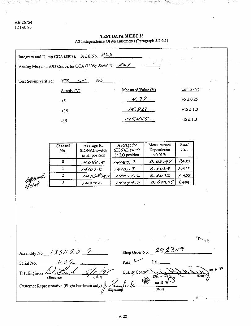
4.4.1 independence of Measurements
This test is performed using the Analog CCA Test Fixture, the Integrate and Dump Filter and the AnalogMux and A/D Converter CCAs. The test gives a measurement of the sample-to-sample crosstalk within a
•channel, which is dependent on the completeness of the dump of the integration capacitor. Test data is
presented on TDS 15.

Report 111598 June 1998
4.4.2 Integrate/dump filter, radiometric data multiplexing, and digitization tests
In this test, a 2 volt dc signal is input to each integrate and dump filter, and the channel output code fromthe A/D converter is measured. The integrator output waveform is also displayed on an oscilloscope forverification of timing. Test data is presented on TDS 16.
4.4.3 Temperature monitoring circuits
In this test a resistor of value approximating the room temperature of the PRTs is connected at the input ofeach PRT readout circuit, and the output code from the A/D converter is measured. The reference voltageused in the PRT readout circuits is also measured. Test data is presented on TDS 17.
4.4.4 Analog telemetry
In this test each of the analog telemetry signals is measured at the ANALOG HSKP jack on the TRU. Test
data is presented on TDS 18.
4.5 Scan Drive
This test includes all CCAs involved in the scan drive function. The circuitry is programmed to provide one
complete revolution of the drive motor as it steps through each of the thirty scene positions and the twocalibration positions. The circuitry is programmed to park at the Warm Cal, Cold Cal, and the Nadirpositions during the test sequence. The GSE test modes are also verified. To verify proper performance,the inertia disk on the motor shaft is visually observed through the one revolution and the various
calibration positions. Test data is presented on TDS 19.
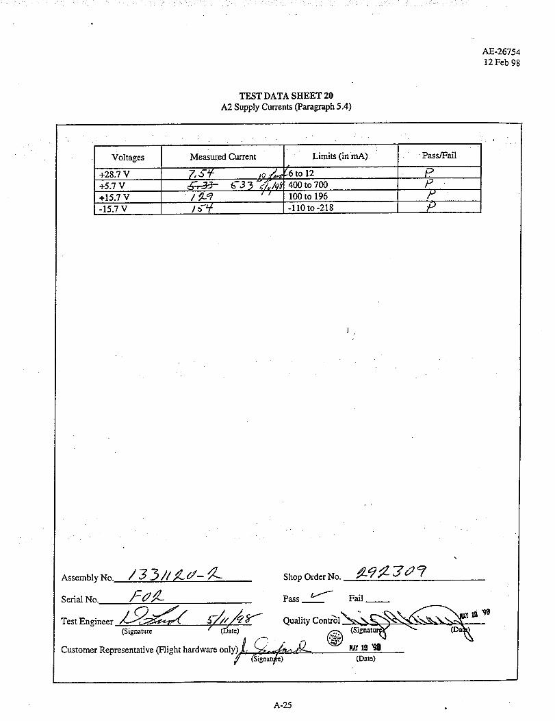
4.6 Supply Current
In this test, the total current drawn by the signal processor from each of the four supply voltages ismeasured with the signal processor fully populated with CCA's. Test data is presented on TDS 20.
5.0 TEST ANOMALIES
One test anomaly occurred. The anomaly occurred when the motor did not move to the positioncommanded. The test was stopped and a Test Anomaly Report (attached) was opened (TAR 002393).Troubleshooting revealed that the old/new switches (SW1 & SW2) on the Motor Driver Test Fixture
(SK1293785) were found to be intermittent, resulting in improper motor drive. The Test EquipmentAnomaly Report (TEAR 0007) was opened, and the switches were removed and replaced. Then the testwas continued until completion.
6.0 TEST RESULTS
The METSAT/AMSU A2 SIGNAL PROCESSOR TEST was successfully completed and all test data is
within specified limits.

AE-26754
12 Feb 98
TEST DATA SHEET 11
A2 Continuity Tests (Para_aph 5.2.1)
Enter a Pass or Fail to indicate the result of the tests:
From
E1
E2
E3
"_24-73
J324-75
To
.I301-60 _-----.--
J301-90
J324-76
J302-46
J312-70
[312-89
I312-91
Signal Name
CHASSIS GND
cHAssiso_ , .-cHAssisGND
CHASSIS GND
1.248 MHZ PS CLK
5V RTN(1) (1.248 MHZ PS CLK RTN)
5V RTN(1) (PS CLK SHIELD)
Pass/Fail
Ji
"3,,
shopO_derNo. _'_"e" 3 o ?Assembly No. / _ _ t// _ _- _
Serial No. _ 0 _- PassS Fail _ _ _
TestEn_neer __ _-'////_ -_ QualityC°n tr°l'_-_--"__'_"--'_'_'_/_(r'_AtllAe_- -• (Date) -= (Signa_ -_
- (Signature -- _ _1 12 _i_3
Customer Representative (Flight hardware only) ,_ _--/_'-_t,_1• _/(Sig'nat_) (Date) ---.-----
A-15

_i; ;_ ;ii;_'ii: ii/iii_!(/,_ _'• • • ' :i_: ¸ _ : : ; i ¸• ; i _ •
AE-2675412 Feb 98
TEST DATA SHEET 12
A2 PowerDistribution (Paragraphs 5.2.2 & 5.2.3)
f PowerSupplyVoltages: ,(
Verified: YES_ NO______--
Connector +5 +15 -15 +28 +9No. ±0.5V ±0.3 V ±0.3V . +0.56V +_IV_
J301
2 J302
3 \\ J303
4 \J304
5 J3G5
6 J306 \,\
6 J307
6 J308
6 J309
6 J310
6 J311
6 J312
6 J313
6 J315
6 J317
6 J318
6 J320
6 J321
6 J322
6 J323
7 J325
Assembly
Test Engineer _(_f_ ¢_¢
(Signature
Customer Representative (Flight hardware only) ,_.,__. ,d',._.--_-- (Signature'-" "
q,e7
A-16

AE-2675412Feb98
TEST DATA SHEET 13 (Sheet 1 of 2)
A2 Digital Processor (Para_aph 5.2.4)
CPU CCA SerialNo. 0312)_ _ fO _
scanC0n olInte ac CCASerialNo.(J315) /•Timing and Control CCA Serial No. 0311) if7 :e_
5.2.4.1 Memory tests:
5.2.4.1/10 Circle PASS or FAlL to indicate the result of the tests:
If "Fail", record the error code and error description.
Error Code: /Q,//_
Error Description: /V//'_
5.2.4.2 CPU tests:
5.2.4.2110Measurements Limits
Vp-p 3, '_ "_ 0/ 3.30- 4!94 V
• T ,_g_ 2_ 761-841 ns
5.2.4.2/-LH). Circle PASS or FAIL to indicate if LEDs indicate CCA passed or failed:
5.2.4.3 Scan Control Interface Tests:
5.2.4.3/14 The input ports 0 and 1 tests
5.2.4.3/21 Inhibit input port 0 and 1 tests
5.2.4.3/29 The input ports 2 and 3 tests
5.2.4.3/40"['1 The output ports 0 and 1 tests
If "Fail", record the error code and error description.
Error Code: - /
Error Description: "/U///_/
A-17
Fail
Pass/Fail.
/¢_o75;$- .
_ Fail
Fail
Fail
Fail
Fall

AE-26754
12 Feb 98
TEST DATA SHEET 13 (Sheet 2 of 2)
A2 Digital Processor (Para_aph 5.2.4)
5,2.4.4 Timing and Control Tests: 65.2.4.4/13 The Inte_ate and Hold pulse and the Dump pulse at the card rack slot J307.
5.2.4.4125 The Inte_ate and Hold pulse and the Dump pulse at the card rack slot J301.
5.2.4.4/47
The Antenna Strobe pulse test. _ _
The test of the interface to the Temp. Sensor Analog Mux card rack slot J303.
The test of the interface to the Analog Mux and Converter card rack slot
J308.
If "Fail", record error code and error description:
Error Code: -- /
Error Description: "Ac'//_-- /
Fail
Fail
Fail
Fail
Fail
A-18

i_ill_'ii!i_!IIii(ii_I:I_i?_i?ii_i_:i;,:__ •
" AE-2675412 Feb 98
TEST DATA SHEET 14
A2 Relay Driver Tests (Paragraph 5.2.5.2)
Spacecraft Interface #2 CCA (J308) Ser. No. _ _ _" / --
Spacecraft Interface#1 CCA (J309) Ser. No. /_' [ __ .....
Parallel to Serial Converter CCA (J310) Serl Nol /=_- O _ ' "
Relay Driver And Current Monitor CCA (J317) Ser. No. _/'_ (9 _ _
STE Self Test: Pass _''': Fail
Test Set-up Verified:
Step No.
_ze
3_3q
3_ _L
Yes NO .__._.--
Test Description
Module power connects
-Survival heater power turns on
Survival heater power turns off
Module power disconnects
S"_nanner 2 power turns on
Compensator motor power turns on
Scanner 2 power turns off
-_ompensator motor power turns off
Module power disconnect
._.___.----.-----
P
Assembly No. / 3 3//_" 62 _ _. Shop Order No. ,_'9_ _ _ _
.-_. Pass_ FailSerial No /-- U 7- . . _ t_
/,, _ " uali tsontro_ _ ...... -/ ( ) _ 1{" 6///'/_ 2" Q ty --..: - _- :_,-,." _ (Date)_Test Engineer ""1 r_"_'4"we" " / ' te - t_ \
- CSi_aature (Da) . " _ _--_'___
_ • • - l-, 1 ._ J_-v- m_?, _ 'Customer Representative It'light narflware on y,7/ iSigna_ureT_ " " (Date, i
A-19
AE-2675412Feb98
TESTDATA SHEET 15
A2 Independence Of Measurements (Paragraph 5.2.6.1)
Integrate and Dump CCA (3307): Serial No. _'g,,g
Analog Mux and A/D Converter CCA (J306): Serial No. f,_7
Test Set-up verified: YES /-,--"" NO
Supply (V)
+5
+15
-15
Measured Value (V)
_,77
/_. ?_
Limits (V)
+5 + 0.25
+15 + 1.0
-15 + 1.0
Channel
No.Average for
SIGNAL switch
in Hi position
/,i,'a _. e
Average forSIGNAL switch
in LO position
/.,-/1ol, 3
Measurement
Dependence_<0.01%
1_,_0,_7¢,7 /_t_o 77. ¢.. 0, 00 57-
3 i,t, zo.l¢_ /qxo7,_. __ o, _o7..7._"
Pass/
Fail
P,,_ sat
pA-_r
Assembly No. / 3 3// _ d- _'- Shop Order No.
Serial No. /_ (_2 __ Pass / Fail
5.ce_ 3o_
.,,..
,.,.¢
Test En_neer _,_Wt "/ (/'_/t / _f Quality Control"X_..._. __'__'_ llX_t_ '"
(sig.._o _D._,_ • _ _s_-)_N _ "_- - --c_,_Customer Representative (Fli=ht hardware only) _._-_._-£,_.- _ last 12 '98"_-a
_/_ (Signatur_ - (Dam)
A-20

TESTDATASHEET 16
A2 Integrator Signal Multiplexing, And Digitization (Paragaph 5.2.6.2)
AE-26754
12 Feb 98
Analog Mux and A/D Converter CCA(J306):
Inte_ate and Dump/Filter CCA (J307):
Ser. No. F'O "1'
Ser. No./_'2-_J
V1
Output Waveform
1_.32 :)2. ms
, ,190=9.5 msJ
V2
Channel " Data . Data Limits DataPass/Fail
IntegratorWave form
Pass/Fail
1 2. 7_5t1 26125 to 29757 P,45_ Pkg$
2 Z q _ 5 9 26125 to 29757 PA _;.._ PA $.¢
Signal Name Pass/Fail
Dump PA'$.¢
+5 Vdc GSE Interlock A PA $_'"
+5 Vdc GSE Interlock B p_5_
Assembly No. / 33//,_ d- _L Shop OrderNo. ,_ 9_ 3 _e::_
Serial No. /t'_g_7 __ Pass. _ Fail__ i...... --_x-
Test Engineer _<__ f////q Y Quality Contro'l" ,__. _ ,_,_,_ _.,_.N_,, _11_ "
Customer Representative (Flight hardware only) / ._-'-./_l.,_-_q _ _ LJ
' (Signatul{)- (Date)
A-21

.......i ¸ !i)_ .(!.::/ : i : ¸:¸ : : ' :
AE-2675412 Feb 98
TEST DATA SHEET 17
A2 Temperature Monitoring Circuits (Para_aph 5.2.6.3)
Temperature Sensor Analog Mux CCA (J303) Serial No.
Temperature Sensor B CCA (J304) Serial No. :_
Temperature Sensor A CCA(!305) Serial No. ]'- / 5
Dig. A Temp No. Description
1 Scan Motor
2 Feedhom
3 RFMUX
Mixer IF CH 1
5 Mixer IF CH 2
6 LO Channel 1
7 LO Channel 2
10
Comp Motor
Subreflector
Dc/Dc Converter
11 RF Shelf
12 Det/Preamp
13 Warm Load Cntr
14 Warm Load 1
15 Warm Load 2
16 Warm Load 3
17 Warm Load 4
:/3
Data
¢3oqI_
?o 7_ 7
307ao
3oq2 _ -
_o_ _ "
z.'z.'c,c,,t,.
Z2. q7¢o
z2. _a,/
18 Warm Load 5 7_ _L/
19 WarmLoad6 ;._ '-/3g /20 Thermal Reference _ _-0_"_
Data Limits
28259 to 32513
28259 to 32513
28259 to 32513
28259 to 32513
28259 to 32513
28259 to 32513
Pass/Fail
P
PP
?PP28259 to 32513
28259 to 32513 /_
28259 to 32513 /.9
28259 to 32513
28259 to 32513
28259 to 32513
20339 to 23401
20339 to 23401
20339 to 23401
20339 to 23401
20339 to 23401
20339 to 23401
20339 to 23401
23340 to 26320
P
PPPP
?r_
Assembly No. /,_,_//5_- : -- _- Shop Order No. : _ '_ _ : e_,
Serial No. /_" : _ Pass _ Fail __
Test Engineer e_, ,_ Quality Contr
(Signature " (Date, _ (Signatu_ _ (I_
Customer Representative (Flight hardware only) _. _-_-- , _ --.-_-_(_. _'!:_Y_ '9__(Signat_5 (mt_)
\
A-22

TEST DATA SHEET 18
A2 Analog Telemetry (Para_aph 5.2.6.4)
AE-26754
12 Feb 98
ANALOG HSK.PSwitch Position•
2
•DV'M Reading
fv)- Limits ('V)
2.85 to 3.15
3.30 to 3.66
2.87 to 3.17
2.85 to 3.15
3.30 to 3.66
Pass/Fail -
PP?PP
6 2.87 to 3.17 p
10 3, :_-_ 3.42 to 3.78 /_9
12 2.84 to 3.14
13
21 O, ooz_-
21 _. 9L
_,_6_,_, s_ 2.84 to 3.14
-0.05 to 0.05
O, oo_ r
2.8 to 3.4
-0,05 to 0.05
2.8 to 3.4
22
22
PPPF?
P
Assembly No. / 3Z//_ d-afl-_- Shop Order No. ,_-_ 3 #_'_ "
se_alNo./-rO_- Pass_ Fail
TestEngineer _,-'_,__ ._-/_/_ _ QualityControl _%x,t-_x___x__--_l_ 'q8
(Signatt_ / (Date) (Signature_ -'_'_- (D_
Customer Representative (Flight hardware only) 1;_(__,,¢_,_.,,_ _ II_v,_ '98/ (s,**-_t_') " (_te)
A-23

AE-26754
12 Feb 98
TEST DATA SHEET 19
A2 Scan Drive/Compensator Drive/Signal Processor Tests (Paragaph 5.3.1)
A2 Scan Drive Subsystem CCAs:
Interface Converter CCA (3318) Ser. No. /_Z _ O
Resolver Data Isolator CCA 0320) Ser. No. F _ 7R/D Converter/Oscillator CCA (J321) Ser. No. F/_)
Motor Drive 3-hall sensor CCA (3322) Ser. No. /L" O/
,/"Test Set-up Verified: Yes _ No
Para./Step No. Mode Pass/Fail
5.3.1.2.1/12 Motor in warm cal position
5.3.1.2.2/3
5.3.1.2.3_
5.3.1.2.3/3
5.3.1.2.3N
5.3.1.2.3/5
5.3.1.2.4/5
5.3.1.2.5/9
5.3.1.2.6/4
5.3.1.2.7N
5.3.1.2.8N
5.3.1.2.9N
5.3.1.2.9_
5.3.1.2.10/2
Motor in nadir position.
Motor in cold cal position 1
Motor in cold cal position 2
Motor in cold cal position 3
Motor in cold cal position 4
Motor in full scan mode
GSE mode 2
GSE mode 4
GSE mode 5
P
PPP
,2
P
PP
GSE mode 1
GSE mode 3 P
GSE mode 7 /9
Scan power off
p .
P
A2 Compensator Drive.Subsystem CCAs:
Motor Driver 3-hall Sensor CCA (3323) Ser. No.
Test Set-up Verified: Yes _ No
F//
Para./Step No. Mode Pass/Fail
5.3.2.214 Compensator motor operation P
5.3.2.2/5 Power-off test of compensator motor /-_
Assembly No. / 3 5 )/.,_ O --.if, Shop Order No. ,,_ _ _ _ C2
Serial No. /_"O£ Pass i Fail
Test Engineer _,_-_ ,_1/,,,,_ _ Quality Control__--_,__ _'t kq _
(Signature /(Dat_) _ (Signat_N" "_ - -- (]_ate)
Customer Representative (Flioht hardware only) Q. f<A_,_ ,_
(Signat_> (Date)
A-24
AE-2675412Feb98
TEST DATA SHEET 20
A2 Supply Currents (Para_aph 5.4)
• ) . .
Voltages Measured Current
+28.7 V 7,_-_
+5.7 V
+15.7 V
-15.7 V
I /
• Limits (in mA).
,/6to 12
400 to 700
100 to 196
-I10to-218
Pass/Fail
P i
•P/-,P
Assembly No. //3 3//_- _'¢--_ Shop Order No. _-q _ _ O
Serial No. J_'C'7,_ _- Pass _ Fail
Test Engineer __f__"_ .6"/_////_ _'" Quality Con_'61____ _1_
Customer Representative (Fli=ht hardware only) 1: "_._
A-25 °

clc 0o-3so -o7G|TAR NO. ISYSTEM NO. I ss002393 A YNAME ,,,_-"r,._._-r ,4.Z.
TEST ANOMALY RECORD DATE _"/_A_P Page l of _ _ql,#' ASSYP/N /3_7//7-0-'Z. REV.___.
SPEC (MPI, AE .... ) A _'''_'_V .L_ ASSY S/N _: o_
CUMULATIVE TIME ,--- hrs i rain S/O NO. Z_2 3OC7
(REF. MP100-005) ELAPSED TIME _ hrs.._mln TEST OPER NO. O/._,_STEP
First time for failure at this point? YESL'_ NO . TestProcParaNo. where failure occurred _',',_, /.2_. _"
Type of test (EXP: T/C 1FFT HOT) JC'C/,aJ_ 7"/o _A-t.- Para Step No. 7
DESCRIPTION OF ANOMALY (LIST EXPECTED AND RECORDED VALUES): //V'_'_-7"/,A-
"7-_ /Z- otcz...oc_.. Po_;/7-/oA/," _/_:_ ,_,'Q-'r j,.,/_v,_"/
D / S /<C S,/,/ot.J/-..D # _
• OTIFIED TEAM LEADER NAME _, /_'/E-F'o .7,/_ ,f_j__j_ _/j>/_,
INSTRUCTIONS: . I
OPER. STATION_.. %-_ Test to notify inspection of failure/anomaly. (Except en.qineerin.q r MPI or Pretest.)
_____c_ Inspection to notify DCMC of failure / anomaly. (GFE) Dc#t_ _>. ,_.e6_eD .6"/_'/_ _:
TROUBLESHOOT/REWORK/RETEST ACTION PLAN:
NOTE: Remove pink copy here. Deliver to QA drop box. '--ITEAM'"L\_,_E_DERy_,_'
TROUBLESHOOT/REWORK/RETEST/INSTRUCTIONS:OPER. STATION INSP
#X':¢_,b :_.,n-q'zc=
RMP
_0_0
@?-_i'v" _.),,z,,c_A.,-r
"7"E_ "7"
replacement continuation page is MANDATORYart _ Retest/Start( I_ ....
T_H(_oc_DATE TECH DATE ._ru._,,,J,.U/_..Oz__. PAGE /C>
_"" _,T WAS THE CAUSE OF THE ANOMALY? I CORRECTIVEACTION:
- _I'!Deliver completed yellow copy to QA drop box; Completed original to parent S/O _ "
_EAMATtADEE

NFSD 89-0 (June 30, 1989)FORMS
53-55
National Aeronautics andSpace Administration
Report Documentation Page
; 1. Report No. 2. Government Accession No.
4. Title and Subtitle
Integrated Advanced Microwave Sounding Unit-A
(AMSU-A), Engineering Test Report
7. Author(s)
D. Luu
9. Performing Organization Name and Address
Aerojet
1100 W. HollyvaleAzusa, CA 91702
12. Sponsoring Agency Name and Address
NASA
Goddard Space Flight Center
Greenbelt, Maryland 20771
3. Recipient's Catalog No.
3. Report Date
8 June 1998
_. Performing Organization Code
8. Performing Organization Report No.
11159
10. Work Unit No.
11. Contract or Grant No.
NAS 5-32314
13. Type of Report and Period Covered
Final
14. Sponsoring Agency Code
15. Supplementary Notes
16. ABSTRACT (Maximum 200
words )
This is the METSAT A2 Signal Processor Engineering Test Report (P/N 1331120-2, S/N
F02) for the Integrated Advanced Microwave Sounding Unit-A (AMSU-A).
17. Key Words (Suggested by Author(s))
EOS
Microwave System
19. Security Classif. (of this report) 20. Security Classif. (of this page)
Unclassified Unclassified
18. Distribution Statement
Unclassified --- Unlimited
NASA FORM 1626 OCT 66
21. No. of pages 22. Price
NASA FAR SUPPLEMENT 18-53.303-1626

53-56 FORMS (June 30, 1989) NFSD 89-0
PREPARATION OF THE REPORT DOCUMENTATION PAGE
The!ast page of a report facing thethird cover is the Report Documentation Page RDP. Information presented on this page isusea in announcing ana cataloging repor[s as well as prepan_n,g the cover ane t t e page. Thus, it is important that the mTorma[tonbe correct. Instructions Tor filing m each block of the Term are as TOIIOWS:
Block 1. Report No. NASA report series number, if
preassigned.
Block 2. Government Accession No. Leave blank.
Block 3. Recipient's Catalog No.. Reserved for use by each
report recipient.
Block 4. Title and Subtitle. Typed in caps and lower case with
dash or period separating subtitle from title.
Block 5. Report Date. Approximate month and year the report
will be published.
Block 6. Performing Organization Code. Leave blank.
Block 7. Authors. Provide full names exactly as they are to
appear on the title page. If applicable, the word editor should
follow a name.
Block 8. Performing Organization Report No. NASA installation
report control number and, if desired, the non-NASA performing
organization report control number.
Block 9. Performing Organization Name and Address. Provide
affiliation (NASA program office, NASA installation, or contractor
name) of authors.
Block 10. Work Unit No. Provide Research and Technology
Objectives and Plants (RTOP) number.
Block 11. Contract or Grant No. Provide when applicable.
Block 12. Sponsodn,q Agency Name and Address. National
Aeronautics and Space Administration, Washington, D.C. 20546-
0001. If contractor report, add NASA installation or HQ program
office.
Block 13. Type of Report and Pedod Covered. NASA formal
report series; for Contractor Report also list type (interim, final)
and period covered when applicable.
Block 14. Sponsoring Agency Code. Leave blank.
Block 15. Supplementary Notes. Information not included
elsewhere: affiliation of authors if additional space is required
for Block 9, notice of work sponsored by another agency, monitor
of contract, information about supplements (file, data tapes, etc.)
meeting site and date for presented papers, journal to which an
article has been submitted, note of a report made from a thesis,
appendix by author other than shown in Block 7.
Block 16. Abstract. The abstract should be informative rather
than descdptive and should state the objectives of the
investigation, the methods employed (e.g., simulation,
experiment, or remote sensing), the results obtained, and the
conclusions reached.
Block 17. Key Words. Identifying words or phrases to be used
in cataloging the report.
Block 18. Distribution Statement. Indicate whether report is
available to public or not. If not to be controlled, use
"Unclassified-Unlimited." If controlled availability is required,
list the category approved on the Document Availability
Authorization Form (see NHB 2200.2, Form FF427). Also
specify subject category (see "Table of Contents" in a current
issue of STAR ) in which report is to be distributed.
Block 19. Secudty Classification (of the report). Self-
explanatory.
Block 20. Secudfy Classification (of this page). Self-
explanatory.
Block 21. No. of Pages. Count front matter pages beginning with
iii, text pages including internal blank pages, and the RDP, but
not the title page or the back of the title page.
Block 22. Price Code. If Block 18 shows "Unclassified-
Unlimited," provide the NTIS price code (see "NTIS Pdce
Schedules" in a current issue of STAR) and at the bottom of the
form add either "For sale by the National Technical Information
Service, Springfield, VA 22161-2171" or "For sale by the
Superintendent of Documents, U.S. Government Printing Office,
Washington, D.C. 20402-0001," whichever is appropriate.

53-301-298 FEDERAL ACQUISITION REGULATION ('FAR)
GENERAL INSTRUCTIONS FOR COMPLETING SF 298The Report Documentation Page (RDP) is used in announcing and cataloging reports. It is important that this information beco.nsistent with the rest of the report .particulady .the.cover and title page. instructions mr filing in each block of the formTo ow. t s mportant to stay w th n the lines to meet opt cal scann ng requ rements.
Block 1. Agency Use Only(Leave blank)
Block 2. Report Date Full publication date including day,
month, andyear, if available (e.g.,1 Jan 88). Must cite at least
the year.
Block 3. Type of Report and Dates Covered. Statewhetherreport is interim, final, etc. If applicable, enter inclusive report
dates (e.g., 10 Jun 87 - 30 Jun 88).
Block 4. Title and Subtitle A title is taken from the part of the
report that provides the most meaningful and complete
information. When a report iffrepared in more than one volume
report the pdmary title, add volume number,and include subtitle
for the specific volume. On classified documentsenter the title
classification in parentheses.
Block 5. Funding Numbers To include contract and grant
numbers; may include program element number(s), project
number(s), tasksnumber(s), andwork unit number(s). Use the
following labels:
C Contract PR ProjectG Grant TA Task
PE Program WU Work UnitElement Accession No.
Block 6. Author(s). Name(s) of person(s) responsible for
writing the report, perforrningthe research, or credited with the
content of thereport. If editoror compiler, this shouldfollow the
name(s).
Block 7. Performing Organization Name(s) and Address(es).
Self-explanatory.
Block 8. Performing OrganizafionReport Number. Enterthe
unique alphanumeric report number(s) assigned by the
organization performing the report.
Block 9. Sponsodng/Monitodng Agency Name(s) and
Address(es) Self-explanatory.
Block 10. Sponsoring/Monitodn£,Agency Reports Number. (ff
known).
Block 11. SupplementaryNotes. Enter informationnot included
elsewhere such as: Prepared in cooperation with ...; Trans. of
...; To be published in ... When a report is revised, include a
statementwhether the new report supersedes or supplements
the older report.
Block 12.a Distribution/Availability Statement.Denotes public
availability or limitations. Cite any availability to the public.
Enter additional limitations or special markings in all capitals
(e.g., NOFORN, REL, ITAR).
DOD - See DoDD 5230.24Distribution Statement on
Technical Documents
DOE - See authodties.
NASA - See Handbook NHB 2200.2.
NTIS - Leave blank.
Block 12.b Distdbution Code.
DOD - Leave blank.
DOE Enter DOE distribution categories from the
standard Distribution for Unclassified
Scientific and Technical Reports.
NASA - Leave blank.
NTIS - Leave blank.
Block 13. Abstract. Include a bdefMaximum 200 word);
factual summary of the most significant information contained in
the report.
Block 14. Subject Terms. Keywords or phases identifying major
subjects in the report.
Block 15. Number of Pages.Enter the total number of pages.
Block 16. Pdce Code. Enter appropdate price codel_TIS
only).
Block 17- 19.Secudty Classifications. Self-explanatory. Enter
U.S. Security Classification in accordance with U.S. Secudty
Regulations (i.e., UNCLASSIFIED). If form contains classified
information, stamp classification on the top and bottom of the
page.
Block 20. Limitation of Abstract.This block must be completed
to assign a limitation to the abstract. Enter either UL (unlimited)
or SAR (same as report). An entry in this block is necessary if
the abstract is to be limited. If blank, the abstract is assumed to
be unlimited.
Standard Form 298 Back(Rev. 2-89
53-86

DOCUMENT APPROVAL SHEET
Aiai=iclglI=-'rTITLE
METSAT A2 Signal Processor Engineering Test Report (P/N: 1331120-2,
S/N: F02)
DOCUMENT NO.
Report 11159
8 June 1998
INPUT FROM: DATE CDRL:
D. Luu 207
CHECKED BY: DATE
SPECIFICATION ENGINEER: DATE
JOB NUMBER: DATE
APPROVED SIGNATURES DEPT. NO. DATE
Product Team Leader (A. Nieto) J_'_-/',/'; _4
Systems Engineer (R. Platt) _ _'_,,,/ /_-_d
Design Assurance (E. Lorenz) (_._. '_;'¢'._
Quality Assurance (R. Taylor) _/"dl=::_------ ,,_
Technical Director/PMO (R. Hauerwaas) &;;;_6)'/'_k f_
Configuration. Management (J. Cavanaughi_'f 't.v_L,_& _'L u-_ "-
i
/J
By my signature, I certify the above document has been reviewed by me and concurs with the technicalrequirements related to my area of responsibility.
8341
8311
8331
7831
4001
8361
_,/l _r/,¢j'
RELEASE (Data Center) FINAL
Please return this sheet and the reproducible master to Jim Kirk (Bldg. 1/Dept. 8631), ext. 2081.

PART 53 - FORMS 53.301-298
FormApprovedREPORT DOCUMENTATION PAGE OMB No.
0704-0188
Public reporting burden fo(hls collection oflnformatlon is estimatedto average 1 hour per response,including the timefor reviewing tnstructions,seamhing existing data' source
gathering and'nalntalnlng thedata needed,and completing andreviewing thecollection Information. Send comments regardingthis burden estimate or any other aspect of this
collection of info'rmation, including suggestiofm" reducing this burdento Washington Headquadera Se,,vlcesDirectorate for Information Operation=and Reports, 1215 Jefferso
Davis Highway, Suite 1204, Arlington, VA 22202-4302, and to the Office of Management and Budget, Paperwork Reduction Project (0704-018B). Washington, DC 20503.
1. AGENCY USE ONLY ( Leave 2. REPORT DATE
blank )
4. TITLE AND SUBTITLE
Integrated Advanced Microwave Sounding Unit-A(AMSU-A), Engineering Test Report
6. AUTHOR(S)
D. Luu
7. PERFORMINGORGANIZATIONNAME(S)ANDADDRESS(ES)Aerojet
1100 W. Hollyvale
Azusa, CA 91702
9. SPONSORING/MONITORING AGENCY NAME(S) AND ADDRESS(ES)NASA
Goddard Space Flight Center
Greenbelt, Maryland 20771
3. REPORT TYPE AND DATES COVERED
5. FUNDING NUMBERS
NAS 5-32314
8. PERFORMING ORGANIZATION
REPORT NUMBER
111598 June 1998
10. SPONSORING/MONITORING
AGENCY REPORT NUMBER
11. SUPPLEMENTARY NOTES
uul
12a. DISTRIBUTION/AVAILABILITY STATEMENT 12b. DISTRIBUTION CODE
13. ABSTRACT (Maximum 200
words )
This is-the METSAT A2 Signal-Processor Engineering Test Report (PIN 1331120-2, SINF02) for the Integrated Advanced Microwave Sounding Unit-A (AMSU-A).
14. SUBJECT TERMS
LOSMicrowave System
17.SECURITY CLASSIFICATIONOF REPORT
Unclassified
NSN 7540-0t-280-5500
18. SECURITY CLASSIFICATIONOF THIS PAGE
Unclassified
19. SECURITY CLASSIFICATIONOF ABSTRACT
Unclassified
15. NUMBER OF PAGES
16. PRICE CODE
m.m
20. LIMITATION OFABSTRACT
SAR
Standard Form 298 (Rev, 2.Ba)Prescrted by ANSI Std 239-18
298-102