aeration of volatile organic compounds using gas
TRANSCRIPT

Journal of Mechanical Engineering Research Vol. 4(7), pp. 213-224, November 2012 Available online at http://www.academicjournals.org/JMER DOI: 10.5897/JMER12.047 ISSN 2141-2383 ©2012 Academic Journals
Full Length Research Paper
Aeration of volatile organic compounds using gas dispersion impellers
M. K. Verma and R. K. Tyagi
Department of Mechanical and Automation Engineering, Amity School of Engineering and Technology, Amity University, Noida (U.P), India.
Accepted 13 November, 2012
A number of volatile organic compounds (VOCs) are found in the wastewater and some of these VOCs are very harmful to human health as well as environment. Although there are several methods which are being used for the removal of VOCs, air stripping process is the low energy usage, low preventive and maintenance cost and high efficiency process which can stripe VOCs from wastewater. The present study consists of aeration system for the removal of VOCs. Aeration of VOC is based on the mass transfer rate of VOCs from the liquid to gaseous phase. Principle of air stripping involves the mass transfer of volatile organic contaminant from water to air. The system can be easily upgraded to strip greater amount of VOCs with relatively small increase in capital cost. Aeration tanks strip volatile compounds by bubbling air into tank through which contaminated water flows. The present study shows aeration of a VOC by using advanced designed gas dispersing radial impeller that is, Rushton, CD-6 and BT-6 and the factors which affect the design of an aeration tank baffles and the impeller used for best possible result. This study also shows the removal of VOCs at different height of submergence. It also shows the effect of air supply on the removal of VOCs at different operating condition. A comparison of the result from experiment shows the emission rate of VOCs during aeration and is a function of mass transfer coefficient of air; it increases with increase of submergence of height, by supply of air, and increase in impeller speed. Best aeration result can be obtained at the 2/3rd height of the submergence of the total depth of water for impeller used. The study also shows that the gas dispersion BT-6 impeller has larger removal efficiency (up to 96%, with air supply at 4 h run) compare to Rushton and CD-6 impeller. Key words: Volatile organic compounds (VOCs), aeration, mass transfer coefficient, stripping, gas dispersion impellers, Rushton, CD-6, BT-6, gas liquid mass transfer.
INTRODUCTION Mechanical surface aeration is a process that is widely applied in water and wastewater treatment. Probably the most common and best known application is found in the treatment of municipal and industrial wastewater. The effectiveness of mechanical surface aeration depends upon the volatilization of organic compounds and by supplying sufficient oxygen promotes the volatilization. (Matter-Muller, 1998). *Corresponding author. E-mail: [email protected].
This study shows the removal efficiency of mass transfer coefficient of acetone and dichloromethane by using gas dispersion impellers.
There are four primary approaches to estimating emission rates from area sources at animal feeding operations including: (i) the mass balance approach, (ii) indirect methods where ambient concentrations are measured and source emission rates are back-calculated using dispersion models, (iii) micrometeorological techniques where fluxes are calculated from a large footprint using tower-based instrumentation (for example, gradient methods, Eddy covariance), and (iv) direct

214 J. Mech. Eng. Res. methods where fluxes are measured and calculated from the source using portable wind tunnels or flux chambers (Parker et al., 2012).
Waste is a cost of industrial production. Many polluters, including sources of volatile organic compound (VOC) emissions, must now pay for their pollution.
France started charging for VOC emitted into the atmosphere in 1985. As the imposed emission factors values are uniform and not practically suitable for each emission source; governmental estimated VOC emission rates generally exceed actual rates of recovery systems for skimmed oil from wastewater, or devices controlling VOC emissions (Metcalf & Eddy, 2003). Application and examination of alternative VOC emission factors are divided into two stages. First, a polluter must submit a proposal that lists the procedures for obtaining alternative VOC emission factors (Robert et al., 1984). VOC emission rates must be calculated using the aeration rates of aerators, or simulated by the model (Cheng and Fang, 2012).
It is also observed that smaller sized tanks are more energy conservative and economical when compared to big sized tanks, while aerating the same volume of water, and at the same time by maintaining a constant input power in all the tanks irrespective of their size (Sathiyamoorthy et al., 2012).
The objective of this work is to design a high efficiency curved-blade-surface mechanical aerator, which is used to treat municipal and domestic sewage. Aeration experiments were conducted of mild steel sheets to study the design characteristics of curved blade surface mechanical aerator. The paper critically examines three different configurations of aerators, which were developed, fabricated and tested in the laboratory for its various dynamic parameters, such as diameter of (D), speed (N) and immersion depth (h). MODEL DESCRIPTION Mass transfer model is given by Fick`s First law of diffusion. Fick`s first law of diffusion Under no flow conditions, the mass transfer of material is brought about by ``molecular diffusion``. The transfer of mass by molecular diffusion in stationary system can be represented as a function of the concentration gradient as follows:
r = -Dm
x
C
(1)
The negative sign denotes fact that diffusion takes place in the direction of decreasing concentration (Shah, 1966).
Henry’s law for dissolved gases
The equilibrium or saturation concentration of gas dissolved in a liquid is a function of type of gas and the partial pressure of the gas in contact with the liquid. Henry’s law is given by
Pg = (H/PT)xg (2)
Gas-liquid mass transfer
A number of mass transfer theories have been proposed to explain the mechanism of gas transfer across gas liquid interfaces. The simplest and most commonly used is the two-film theory proposed by Lewis and Whitman (1924), and the penetration model (Higbin, 1935). The two-film theory is more than 95% of the situations the result obtained are essentially the same as those obtained with the more complex theories.
Two-film theory
The two-film theory is based on a physical model in which two film exist at the gas-liquid interface, as shown in Figure 1. Two conditions are shown in the figure:
(a) “absorption”, in which a gas is transferred from the gas phase to the liquid phase. (b) “desorption”, in which gas is transferred out of the liquid phase in to the gas phase.
The two films - one liquid and one gas, provide the resistance to passage of gas molecules between the bulk-liquid and bulk-gaseous phases.
Assumptions made in the two-film theory
(a) Concentration and the partial pressure in both the bulk-liquid and bulk-gas phase are uniform (that is, mixed completely). (b) All the resistance to mass transfer is caused by the liquid film.
Under the steady state conditions, the rate of mass transfer of gas through gas film must be equal to rate of transfer through liquid. Using Fick`s first law and according to assumption (b), the overall liquid mass transfer coefficient:
r = KL(Cs-CL) = kG(PG-Pi) = kL(Ci-CL) (3)
Absorption of gases
dt
dCKLa(Cs-Ct) (4)

Verma and Tyagi 215
Fig. 1 Definition
Interface
Transfer
Gas
film
Liquid
film
δg δl Ci
Pi
Turbulent Flow Turbulent Flow
Gas phase
(bulk)
Liquid phase
(bulk)
P
C
(a)
Interface
Transfer
Gas
film
Liquid
film
δg δl
Ci
Pi
Turbulent Flow Turbulent Flow
Gas phase
(bulk)
Liquid phase
(bulk)
P
C
(b)
Figure 1. Definition Sketch for the two film theory of gas transfer: (a) absorption (b) desorption.
0CCs
CtCs
= e
-(KLa)t (5)
Where dt
dC = change in concentration with time,
Cs = gas phase concentration in the bulk gas phase C0 and Ct = Concentration at time t = 0 and t = t respectively (Lewis and Whitman, 1924; Shah, 1966). Efficiency of the system is given by
%100*1(
t
o
C
C (6)
Estimation of KLa
In aeration open vessel were used, that allows the sufficient air volume to avoid significant gas phase saturation above the liquid surface, which allow us to assume Cs = 0 (Chu-Chin et al., 1993). Therefore from the Equation (5), the liquid concentrations changes over time and were used to estimate the mass transfer coefficient KLa using the Equation 7.
)(ln 0ttKC
CLa
o
t
(7)
MATERIALS AND METHODS
Chemical used in this study are acetone and dichloromethane.

216 J. Mech. Eng. Res.
Table 1. Physical and chemical properties of VOCs used.
Property Value (Dichloromethane) Value (Acetone)
Molecular weight 84.9 g 58.08 g
Aspect Liquid Liquid
Melting point - 94.9°C -95.35°C
Boiling point 39 - 40°C at 1.013 Pa -94.7°C at 1 Pa
Density 1.33 g/ml at 20°C 0.78996 g/ml at 20°C
Vapor pressure 475 mm of Hg at 20°C 181.72 mm of Hg at 20°C
Water solubility 13.7 g/L at 20°C 11.7 g/L at 20°C
Table 2. Description of the impeller used.
Impeller Geometrical characteristic of the impeller
D (m) L W DD
D-6 0.1 D/4 D/5 7D/10
CD-6 0.1 D/4 D/5 7D/10
BT-6 0.11 D/4 2D/13 2D/3
(a) D-6 (b) CD-6 (c) BT-6
Figure 2. Impeller used in the study.
Table 1 shows some physical and chemical properties of these chemicals. Impeller used in the study In this study gas dispersion impellers that is, Rushton or D-6 and
hollow blade impellers that is, CD-6 and BT-6 are used (Table 2 and Figure 2). Experimental setup A flat bottom, cylindrical tank with a diameter of T=30 cm, and height of 35 cm with a reactor having a total working volume of 24.74 L and the working volume of water been 16 L and the water height in the tank 22.6 cm were used. Figure 3 shows the schematic setup used in this study. The four equi-spaced baffles, B=0.1T, arranged at the 90° was around the circumference and
were fitted to the wall 0.3 cm of gap between baffle and the wall of tank was provided for better cleaning of baffle. The vessel was constructed of MS sheet. The working fluid was filtered tap water. Air was introduced, via air pump, through 3 mm diameter copper tube and multiple holes are provided at the end of the pipe for better dispersion of air with a clearance of Cs=T/5.
Experimental procedure The experimental setup which is shown in Figure 3 was used for the experiments. All electric connection was made. The reactor was thoroughly washed and cleaned for every set of readings. Laboratory made wastewater was then poured in to the reactor. Prior to start of each run, the content of the tank were thoroughly mixed to ascertain the homogeneity of the wastewater under study. Dissolved oxygen (DO) was removed using sodium sulfite with a cobalt chloride catalyst. The cobalt chloride dose was less than 0.5 mg/L. Theoretically, 7.9 mg/L of sodium sulfite is required for each

Verma and Tyagi 217
T
H
B
Air Inlet
DC Motor (0.2
hp)
H1
Air supply
by air
pump
Fig. 3 Experimental set up
H2
Cs
Figure 3. Experimental setup.
Table 3. Estimated removal efficiency of Rushton impeller.
RPM
Removal efficiency with air supply (%) Removal efficiency without air supply (%)
At height H1 At height H2 At height H1 At height H2
Acetone DCM Acetone DCM Acetone DCM Acetone DCM
250 70.16 66.35 78.57 70.30
300 79.47 78.23 82.14 80.34 72.16 66.65 79.79 69.81
350 81.79 81.05 82.09 84.76
milligram per liter of DO present. Since it is common practice to add 1.5 to 2.0 times of this amount to ensure complete deoxygenating, approximately 14 mg/L per mg of DO was added. After adjusting the impeller height from the bottom of the tank the impeller speed was adjusted by using the tachometer to the desired value which began each experiment. Sample were taken after every 20 min, each experiment run was 4 h for both types of VOCs. RESULTS AND DISCUSSION
Effect of impeller speed on volatile organic compounds (VOCs) removal
Experiment was studied at three higher revolutions per minute that is, 250, 300 and 350 rpm. Graph clearly shows that the removal efficiency is a function of impeller speed and it increases with the increase in impeller speed, for both types of VOCs studied. Graph shows that, initially rate of reduction of VOC is high (up to 2 h),
because the initial VOC concentration was high and after sometime when the concentration reaches value of about 4 mg/L, its removal rate reduced because of low concentration. Graph clearly shows that best result is obtained at 350 rpm, although difference of removal efficiency is not more at 300 and 350 rpm. Tables 3 to 5 shows the efficiency obtained at varying operating condition.
Effect of types of impellers on volatile organic compounds (VOCs) removal
In this study well designed gas dispersion radial impellers that is, Rushton (D-6), CD-6 and BT-6 were selected. These impellers are efficient for gas dispersion application. Graph clearly shows that BT-6 impeller gives best result at all operating conditions (up to 95% removal
218 J. Mech. Eng. Res.
Table 4. Estimated removal efficiency of CD-6 Impeller.
RPM
Removal efficiency with air supply (%) Removal efficiency without air supply (%)
At height H1 At height H2 At height H1 At height H2
Acetone DCM Acetone DCM Acetone DCM Acetone DCM
250 75.84 80.74 82.92 81.40
300 84.53 84.97 87.82 85.18 82.91 78.42 81.61 81.45
350 83.79 86.81 89.63 88.56
Table 5. Estimated removal efficiency of BT-6 Impeller.
RPM
Removal efficiency with air supply (%) Removal efficiency without air supply (%)
At height H1 At height H2 At height H1 At height H2
Acetone DCM Acetone DCM Acetone DCM Acetone DCM
250 89.65 91.69 91.61 92.61
300 93.58 92.26 95.84 93.91 89.68 81.90 91.14 85.03
350 94.91 93.71 95.87 94.05
0
2
4
6
8
10
12
0 50 100 150 200 250 300
Series1
Series2
Series3
250 RPM 300 RPM 350 RPM
Time (min)
Co
nce
ntr
atio
n (
mg/
L)
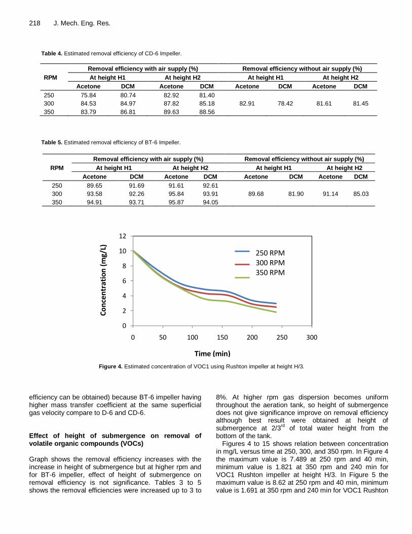
Figure 4. Estimated concentration of VOC1 using Rushton impeller at height H/3.
efficiency can be obtained) because BT-6 impeller having higher mass transfer coefficient at the same superficial gas velocity compare to D-6 and CD-6. Effect of height of submergence on removal of volatile organic compounds (VOCs) Graph shows the removal efficiency increases with the increase in height of submergence but at higher rpm and for BT-6 impeller, effect of height of submergence on removal efficiency is not significance. Tables 3 to 5 shows the removal efficiencies were increased up to 3 to
8%. At higher rpm gas dispersion becomes uniform throughout the aeration tank, so height of submergence does not give significance improve on removal efficiency although best result were obtained at height of submergence at 2/3
rd of total water height from the
bottom of the tank. Figures 4 to 15 shows relation between concentration
in mg/L versus time at 250, 300, and 350 rpm. In Figure 4 the maximum value is 7.489 at 250 rpm and 40 min, minimum value is 1.821 at 350 rpm and 240 min for VOC1 Rushton impeller at height H/3. In Figure 5 the maximum value is 8.62 at 250 rpm and 40 min, minimum value is 1.691 at 350 rpm and 240 min for VOC1 Rushton

Verma and Tyagi 219
0
2
4
6
8
10
12
0 50 100 150 200 250 300
Series1
Series2
Series3
Time (min)
Co
nce
ntr
atio
n (
mg/
L)
Figure 5. Estimated concentration of VOC1 using Rushton impeller at height 2H/3.
0
2
4
6
8
10
12
0 50 100 150 200 250 300
Series1
Series2
Series3
Time (min)
Co
nce
ntr
atio
n (
mg/
L)
Figure 6. Estimated concentration of VOC2 using Rushton impeller at height H/3.
impeller at height 2H/3. In Figure 6 the maximum value is 8.126 at 250 rpm and 40 min, minimum value is 2.013 at 350 rpm and 240 min for VOC2 Rushton impeller at height H/3. In Figure 7 the maximum value is 7.939 at 250 rpm and 40 min, minimum value is 1.524 at 350 rpm and 240 min for VOC2 Rushton impeller at height 2H/3. In Figure 8 the maximum value is 8.648 at 250 rpm and
40 min, minimum value is 1.21 at 350 rpm and 240 min for CD-6 impeller and VOC1 at height H/3. In Figure 9 the maximum value is 8.403 at 250 rpm and 40 min, minimum value is 1.037 at 350 rpm and 240 min for CD-6 impeller and VOC1 at height 2H/3. In Figure 10 the maximum value is 8.363 at 250 rpm and 40 min, minimum value is 1.319 at 350 rpm and 240 min for CD-6

220 J. Mech. Eng. Res.
0
2
4
6
8
10
12
0 50 100 150 200 250 300
Series1
Series2
Series3
Time (min)
Co
nce
ntr
atio
n (
mg/
L)
Figure 7. Estimated concentration of VOC2 using Rushton impeller at height 2H/3.
0
2
4
6
8
10
12
0 50 100 150 200 250 300
Series1
Series2
Series3
Time (min)
Co
nce
ntr
atio
n (
mg/
L)
Figure 8. Estimated concentration of VOC1 using CD-6 impeller at height H/3
impeller and VOC2 at height H/3. In Figure 11 the maximum value is 8.493 at 250 rpm and 40 min, minimum value is 1.144 at 350 rpm and 240 min for CD-6
impeller and VOC2 at height 2H/3. In Figure 12 the maximum value is 7.999 at 250 rpm and 40 min, minimum value is 0.542 at 350 rpm and 240 min for BT-6

Verma and Tyagi 221
0
2
4
6
8
10
12
0 50 100 150 200 250 300
Series1
Series2
Series3
Time (min)
Co
nce
ntr
atio
n (
mg/
L)
Figure 9. Estimated concentration of VOC1 using CD-6 impeller at height 2H/3.
0
2
4
6
8
10
12
0 50 100 150 200 250 300
Series1
Series2
Series3
Time (min)
Co
nce
ntr
atio
n (
mg/
L)
Figure 10. Estimated concentration of VOC2 using CD-6 impeller at height H/3.
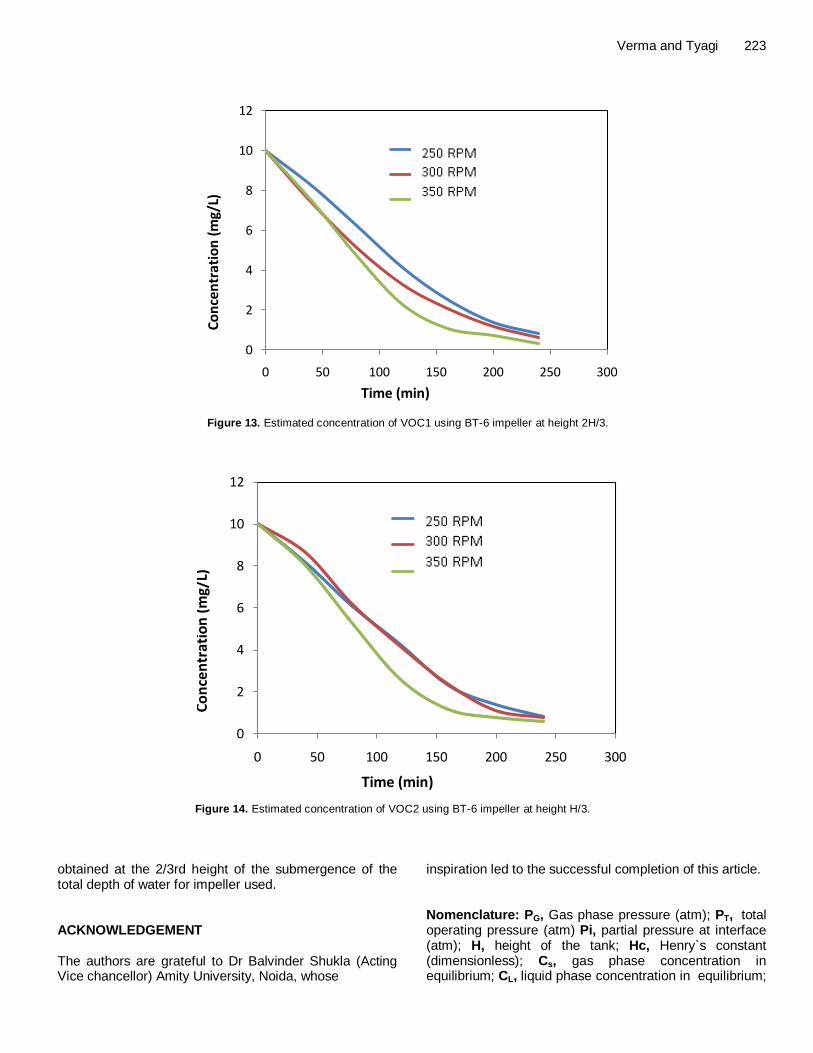
impeller and VOC1 at height H/3. In Figure 13 the maximum value is 8.229 at 250 rpm and 40 min, minimum value is 0.313 at 350 rpm and 240 min for BT-6 impeller and VOC1 at height 2H/3. In Figure 14 the
maximum value is 8.139 at 250 rpm and 40 min, minimum value is 0.603 at 350 rpm and 240 min for BT-6 impeller and VOC2 at height H/3. In Figure 15 the maximum value is 8.206 at 250 rpm and 40 min,

222 J. Mech. Eng. Res.
0
2
4
6
8
10
12
0 50 100 150 200 250 300
Series1
Series2
Series3
Time (min)
Co
nce
ntr
atio
n (
mg/
L)
Figure 11. Estimated concentration of VOC2 using CD-6 impeller at height 2H/3.
0
2
4
6
8
10
12
0 50 100 150 200 250 300
Series1
Series2
Series3
Time (min)
Co
nce
ntr
atio
n (
mg/
L)
Figure 12. Estimated concentration of VOC1 using BT-6 impeller at height H/3.
minimum value is 0.495 at 350 rpm and 240 min for BT-6 impeller and VOC2 at height 2H/3. Conclusion In this article effort was made to find out effect of different
size and profile of impeller on VOC emission in environment. The result obtained by experimental method shows that size and profile of impeller on VOC emission have immense effect. The overall oxygen transfer coefficient (KLa) was observed to be as high as 0.36 h
-1 and the optimum efficiency was found up to 96%,
with air supply at 4 h run. Best aeration result can be
Verma and Tyagi 223
0
2
4
6
8
10
12
0 50 100 150 200 250 300
Series1
Series2
Series3
Time (min)
Co
nce
ntr
atio
n (
mg/
L)
Figure 13. Estimated concentration of VOC1 using BT-6 impeller at height 2H/3.
0
2
4
6
8
10
12
0 50 100 150 200 250 300
Series1
Series2
Series3
Time (min)
Co
nce
ntr
ati
on
(m
g/L)
Figure 14. Estimated concentration of VOC2 using BT-6 impeller at height H/3.
obtained at the 2/3rd height of the submergence of the total depth of water for impeller used. ACKNOWLEDGEMENT The authors are grateful to Dr Balvinder Shukla (Acting Vice chancellor) Amity University, Noida, whose
inspiration led to the successful completion of this article. Nomenclature: PG, Gas phase pressure (atm); PT, total operating pressure (atm) Pi, partial pressure at interface (atm); H, height of the tank; Hc, Henry`s constant (dimensionless); Cs, gas phase concentration in equilibrium; CL, liquid phase concentration in equilibrium;

224 J. Mech. Eng. Res.
0
2
4
6
8
10
12
0 50 100 150 200 250 300
Series1
Series2
Series3
Time (min)
Co
nce
ntr
atio
n (
mg/
L)
Figure 15. Estimated concentration of VOC2 using BT-6 impeller at height 2H/3.
M, molecular weight of solute (g/mol); KLa, Mass transfer coefficient (1/h); Η, removal efficiency (%); B, tank baffle width (m); T, tank diameter (m); CS, Sparger clearance (m); D, impeller diameter (m); DD, impeller central disk diameter (m); W, impeller blade width (m); L, impeller blade length (m); KLa, overall mass transfer coefficient of the constituent. REFERENCES
Cheng WH, Fang YC (2012). Abatement of gaseous VOCs using
activated sludge systems, technology feasibility and cost analysis.
Sustain. Environ. Res. 22(5):295-303. Chu-Chin H, Kyoung H, Stenstrom SR, Michael K (1993). Estimating
emissions of 20 VOCs (diffused aeration and surface aeration). J.
Environ. Eng. (ASCE) 1:119-126. Higbin R (1935).The rate of absorption of pure gas into a still liquid
during short periods of exposure. Trans. AICHE 31:365-388.
Lewis WK, Whitman WG (1924). Principles of gas absorption. Ind. Eng.
Chem. 16:1215-1220. Matter-Muller C (1998). Transfer of VOC from waste to atmosphere.
Water Res. 15:1271-1279.
Metcalf & Eddy (2003). Wastewater engineering: Treatment, disposal and reuse (4
th Edition), Tata McGraw-Hill, New Delhi.
Parker D, Ham J, Woodbury B, Cai L, Spiehs M, Rhoades M, Trabue S, Casey K, Todd R, Cole A (2012). Standardization of flux chamber
and wind tunnel flux measurements for quantifying volatile organic compound and ammonia emissions from area sources at animal feeding operations. Atmos. Environ. pp. 1-12.
Robert PV, Munz C, Dandliker P (1984). Modeling of Volatile Organic Solute Removal by Surface and Bubble Aeration. J. WPCF 56:157-163.
Sathiyamoorthy M, Sanghavi BJ, Tumsa Z, Shemsedin A, Birhane H (2012). Increasing aeration efficiency by redesigning the aerator for a tertiary treatment plant in a nitrogenous fertilizer plant. IJMIE 2:6.
Shah DJ (1966). Introduction to colloid and surface chemistry. Butterworth, London.