advisory us department circular · ac 27 671 control systems - general d-36 ac 27 672 stabthty...
TRANSCRIPT
Advisory US Department of TransportatiOn Circular Federal Aviation Administration
Subject: CERTIFICATION OF NORMAL Date: 9/30/2008 AC No: 27-1B CATEGORY ROTORCRAFT Initiated by: ASW-110 Change: 3
1. PURPOSE.
a. This Advisory Circular (AC) publishes needed changes to the existing AC material as a result of a safety-focused study.
b. This change revises existing material in 6 sections.
c. The change number and the date of the changed material are shown at the top of each page. The vertical lines in the right or left margin indicates the beginning and end of each change. Pages that have different page numbers, but no text changes, will retain the previous heading information.
d. This AC does not change regulatory requirements and does not authorize changes in, or deviations from, regulatory requirements. This AC establishes an acceptable means, but not the only means, of compliance. Since the guidance material presented in this AC is not regulatory, terms having a mandatory definition, such as "shall" and "must," etc., as used in this AC, apply either to the reiteration of a regulation itself, or to an applicant who chooses to follow a prescribed method of compliance without deviation.
2. PRINCIPAL CHANGES. Sections 27.571, 27.679, 27.695, 27.783, 27.901A, and 27.1351 are revised.
3. WEBSITE AVAILABILITY. To access this AC electronically, log on to http://www.airweb.faa.gov/rgl and then click on AC's.

AC 27-1 B, Chg 3 9/30/2008
AC 27-1 B, Chg 3 PAGE CONTROL CHART
Remove Pages Dated Insert Pages Dated
v thru xii. ............................. 9/30/99 & 4/25/06 C-83 thru C-87 ................... 9/30/99 & 2/12/03 0-39 thru 0-40 ................................... 9/30/99 0-45 thru 0-46 ................................... 9/30/99 0-71 thru 0-72 ................................... 9/30/99 E-5 thru E-6 ........................................ 9/30/99 F-53 thru F-56 .................................... 9/30/99
v thru xii ............. 9/30/99, 4/25/06, & 9/30/08 C-83 thru C-88 ................................. 9/30/08 0-39 thru 0-40.2 .............................. 9/30/08 0-45 thru 0-46 ................. 9/30/99 & 9/30/08 0-71 thru 0-72.2 .............. 9/30/99 & 9/30/08 E-5 thru E-6 ...................................... 9/30/08 F-53 thru F-56 .................................. 9/30/08
Signed by Scott A. Horn for
Mark R. Schilling Acting Manager, Rotorcraft Directorate
Aircraft Certification Service
Page ii

AC 27-18, Chg 3 9/30/2008
SUBPART C- STRENGTH REQUIREMENTS( continued)
GROUND LOADS <continued}
Page No.
AC 27.497 Ground Loading Conditions: ................................................................................ C-32 Landing Gear With Tail Wheels
landing Gear With Skids
Landing Gear With Skids
AC 27.501 Ground Loading Conditions: ................................................................................ C-34
AC 27.501A Ground Loading Conditions: ................................................................................ C-35
AC 27,505 Ski Landing Conditions ........................................................................................ C-35
WATER LOADS
AC 27.521 Float Landing Conditions ..................................................................................... C-37
MAIN COMPONENT REQUIREMENTS
AC27.547 Main Rotor Structure ........................................................................................... C-38 AC27.549 Fuselage, landing Gear, and Rotor Pylon Structure ........................................... C-38
EMERGENCY LANDING CONDITIONS
AC27.561 Emergency Landing Conditions - General... ........................................................ C-40 AC27.561A Emergency landing Conditions- General... ........................................................ C-41 AC27.561B Emergency Landing Conditions - General.. ......................................................... C-42 AC 27.561C Emergency Landing Conditions- General... ........................................................ C-43 AC 27.562 Emergency landing Dynamic Conditions ............................................................ C-43 AC27.563 Structural Ditching Provisions .............................................................................. C-81 AC27.563A Structural Ditching Provisions .............................................................................. C-81
FATIGUE EVALUATION
AC 27.571 Fatigue Evaluation of Flight Structure ................................................................. C-83 AC 27.571 A Fatigue Evaluation of Flight Structure for Category A Certification ..................... C-86
SUBPART D ·DESIGN AND CONSTRUCTION
GENERAL
Page No.
AC 27.601 Design ................................................................................................................... D-1 AC 27.602 Critical Parts .......................................................................................................... D-2 AC27.603 Materials ................................................................................................................ D-4 AC27.605 F abrication Methods .............................................................................................. D-4 AC 27.607 Fasteners............................................................................................................... D-5
Page vi

9/30/2008 AC 27-18, Chg 3
SUBPART D- DESIGN AND CONSTRUCTION
GENERAL (contmued)
Page No
AC 27 609 Protection of Structure D-5 AC 27 610 L1ghtnmg Protection D-6 AC 27 610A Lightntng and Stat1c Electncity Protection D-9 AC 27 611 Inspection Provisions D-13 AC 27 613 Matenal Strength Properties D-14
and Destgn Values AC 27 613A Matenal Strength Properttes D-16
and Destgn Values AC 27 619 Spectal Factors D-16 AC 27 621 Casting Factors D-17 AC 27 623 Beanng Factors D-27 AC 27 625 Fttting Factors D-28 AC 27 625A Frtttng Factors D-29 AC27 629 Flutter D-29
ROTORS
AC 27 653 Pressure Ventmg and Dra1nage of Rotor Blades D-31 AC27 659 Mass Balance D-31 AC 27 661 Rotor Blade Clearance D-31 AC 27 663 Ground Resonance Prevention Means D-33 AC 27 663A Ground Resonance Prevention Means D-35
CONTROL SYSTEMS
AC 27 671 Control Systems - General D-36 AC 27 672 Stabthty Augmentation, Automatic, D-36
and Power-Operated Systems AC 27 673 Pnmary Flight Control D-37 AC 27 674 Interconnected Controls D-37 AC 27 675 Stops D-38 AC 27 679 Control System Locks D-40 AC 27 681 L!m1t Load Stat1c Tests D-40 1 AC 27 683 Operat1on Tests D-41 AC 27 685 Control System Deta1ls D-41 AC 27 685A Control System Deta1ls D-42 AC 27 687 Spnng Dev1ces D-43 AC 27 691 Autorotatlon Control Mechamsm D-43 AC 27 695 Power Boost and Power-Operated Control System D-44
Page VII

AC 27-18, Chg 3 9/30/2008
AC 27.723 AC27.725 AC27.727 AC27.727A AC 27.729 AC 27.731 AC 27.733 AC27.735 AC27.737
AC27.751 AC 27.753 AC27.755
AC 27.771 AC 27.773 AC 27.775 AC 27.775A AC 27.777 AC27.779 AC 27.783 AC 27.783A AC 27.785 AC 27.785A AC 27.7858 AC 27.787 AC27.787A AC27.801 AC 27.805 AC 27.807 AC27.807A AC 27.8078 AC 27.831 AC 27.833
AC 27.853 AC27.853A AC 27.855
SUBPART D - DESIGN AND CONSTRUCTION (continued)
Page No. LANDING GEAR
Shock Absorption Tests ....................................................................................... D-47 Limit Drop Test .................................................................................................... D-50 Reserve Energy Absorption Drop Test.. .............................................................. D-50 Reserve Energy Absorption Drop Test ................................................................ D-51 Retracting Mechanism ......................................................................................... D-51 Wheels.... , ............................................................................................................ D-54 Tires..................................................................................................................... D-55 Brakes ................................................................................................................. D-56 Skis ...................................................................................................................... D-58
FLOATS AND HULLS
Main Float Buoyancy ........................................................................................... D-59 Main Float Design ................................................................................................ D-60 Hulls..................................................................................................................... 0-60
PERSONNEL AND CARGO ACCOMMODATIONS
Pilot Compartment. .............................................................................................. D-62 Pilot Compartment View ...................................................................................... D-63 Windshields and Windows ................................................................................... D-68 Windshields and Windows ................................................................................... D-68 Cockpit Controls .................................................................................................. D-68 Motion and Effect of Cockpit Controls ................................................................. D-69 Doors ................................................................................................................ D-72.2 Doors ................................................................................................................... D-74 Seats, Berths, Safety Belts, and Harnesses ........................................................ D-74 Seats, Berths, Safety Belts, and Harnesses ........................................................ D-78 Seats, Berths, Litters, Safety Belts, and Harnesses ........................................... D-80 Cargo and Baggage Compartments .................................................................... D-80 Cargo and Baggage Compartments .................................................................... D-82 Ditching................................................................................................................ D-82 Flight Crew Emergency Exits ............................................................................. D-91 Emergency Exits .................................................................................................. D-91 Emergency Exits .................................................................................................. D-93 Emergency Exits ................................................................................................. D-93 Ventilation ............................................................................................................ D-94 Heaters ................................................................................................................ D-96
FIRE PROTECTION
Compartment Interiors ......................................................................................... D-98 Compartment Interiors ........................................................................................ D-99 Cargo and Baggage Compartments .................................................................... D-99
SUBPART 0 • DESIGN AND CONSTRUCTION (continued)
Page viii
9/30/2008 AC 27-18 Chg 3
FIRE PROTECTION (conttnued)
Page No
AC 27 859 Heatmg Systems D-101 AC 27 861 F1re Protect1on of Structure, Controls, and Other Parts D-105 AC 27 861A F1re Protection of Structure, Controls, and Other Parts D-106 AC 27 863 Flammable FlUid Ftre Protection D-107
EXTERNAL LOAD ATTACHING MEANS
AC 27 865 External Load Attaching Means D-109 AC 27 865A External Load Attaching Means D-110 AC 27 8658 External Load Attaching Means (previously MG 12) D-111
MISCELLANEOUS (DESIGN AND CONSTRUCTION)
AC 27 871 Level1ng Marks D-133 AC 27 873 Ballast Provts1ons D-133
SUBPART E - POWERPLANT
GENERAL
AC 27 901 Installation E-1 AC 27 901A Installation E-5 AC 27 903 Eng1nes E-5 2 AC 27 903A Eng1nes E-7 AC 27 907 Engme V1brat1on E-9
ROTOR DRIVE SYSTEM
AC 27 917 Design E-10 AC 27 921 Rotor Brake E-11 AC 27 923 Rotor Dnve System and Control Mechamsm Tests E-12 AC 27 923A Rotor Dnve System and Control Mechan1sm Tests E-17 AC 27 9238 Rotor Dnve System and Control Mechanism Tests E-18 AC 27 927 Add1t1onal Tests E-19 AC 27 927A Add1t1onal Tests E-21 AC 27 931 Shafttng Cnt1cal Speeds E-21 AC 27 935 Shafttng Jo1nts E-26 AC 27 939 Turbme Engine Operatmg Charactenst1cs E-26
Page1x
AC 27-18 9/30/1999
AC 27.951 AC 27.952 AC 27.953 AC 27.954 AC 27.955 AC 27.955A AC 27.959 AC 27.961 AC 27.961A AC 27.963 AC 27.963A AC 27.9638 AC 27.965 AC 27.967 AC 27.969 AC 27.969A AC 27.971 AC 27.971A AC 27.973 AC 27.973A AC 27.975 AC 27.975A AC 27.9758 AC 27.977
AC 27.991 AC 27.991A AC 27.993 AC 27.995 AC 27.997 AC 27.997A AC 27.999 AC 27.999A
AC 27.1011 AC 27.1013 AC 27.1015 AC 27.1017
Page x
SUBPART E- POWERPLANT (continued)
FUEL SYSTEM (continued)
Page No.
Fuel System - General ..........................................................................................E-29 Fuel System Crash Resistance ............................................................................E-31 Fuel System Independence ..................................................................................E-56 Fuel System Lightning Protection .........................................................................E-57 Fuel Flow ..............................................................................................................E-58 Fuel Flow ..............................................................................................................E-62 Unusable Fuel Supply ...........................................................................................E-64 Fuel System Hot Weather Operation ....................................................................E-65 Fuel System Hot Weather Operation ....................................................................E-67 Fuel Tanks: Generai ............................................................................................E-67 Fuel Tanks: Generai ............................................................................................E-68 Fuel Tanks: Generai ............................................................................................E-68 Fuel Tank Tests ....................................................................................................E-69 Fuel Tank Installation ...........................................................................................E-70 Fuel Tank Expansion Space .................................................................................E-72 Fuel Tank Expansion Space .................................................................................E-72 Fuel Tank Sump ...................................................................................................E-73 Fuel Tank Sump ...................................................................................................E-74 Fuel Tank Filler Connection ..................................................................................E-74 Fuel Tank Filler Connection ..................................................................................E-75 Fuel Tank Vents ...................................................................................................E-76 Fuel Tank Vents ...................................................................................................E-77 Fuel Tank Vents ...................................................................................................E-77 Fuel Tank Outlet ...................................................................................................E-78
FUEL SYSTEM COMPONENTS
Fuel Pumps ...........................................................................................................E-80 Fuel Pumps ...........................................................................................................E-81 Fuel System Lines and Fittings .............................................................................E-81 Fuel Valves ...........................................................................................................E-82 Fuel Strainer or Filter ............................................................................................E-82 Fuel Strainer or Filter ............................................................................................E-83 Fuel System Drains ..............................................................................................E-84 Fuel System Drains ..............................................................................................E-85
OIL SYSTEM
Oil System - General ............................................................................................E-86 Oil Tanks ..............................................................................................................E-86 Oil Tank Tests ......................................................................................................E-87 Oil Lines and Fittings ............................................................................................E-88
9/30/1999 AC 27-1 B
AC27.1019 AC 27.1019A AC 27.1021 AC 27.1027
AC 27.1041 AC 27.1041A AC 27.1043 AC 27.1045 AC 27.1045A
AC 27.1091 AC 27.1091A AC 27.1093 AC 27.1093A
AC 27.1121 AC 27.1123
AC27.1141 AC 27.1141A AC 27.1143 AC 27.1143A AC 27.11438 AC 27.1145 AC27.1147 AC27.1151 AC 27.1163
AC 27.1183 AC 27.1185 AC27.1187
SUBPART E- POWERPLANT (continued)
OIL SYSTEM (continued) Page No.
Oil Strainer or Filter .............................................................................................. E-88 Oil Strainer or Filter .............................................................................................. E-89 Oil System Drains ................................................................................................ E-90 Transmission and Gearboxes: General .............................................................. E-90
COOLING
Cooling - General ................................................................................................. E-92 General ................................................................................................................ E-94 Cooling Tests ....................................................................................................... E-94 Cooling Test Procedures ..................................................................................... E-97 Cooling Test Procedures ..................................................................................... E-98
INDUCTION SYSTEM
Air Induction ......................................................................................................... E-99 Air Induction ....................................................................................................... E-100 Induction System Icing Protection ...................................................................... E-100 Induction System Icing Protection ...................................................................... E-111
EXHAUST SYSTEM
General .............................................................................................................. E-113 Exhaust Piping ................................................................................................... E-114
POWERPLANT CONTROLS AND ACCESSORIES
Powerplant Controls: General ........................................................................... E-117 Powerplant Controls: General ........................................................................... E-118 Engine Controls ................................................................................................. E-118 Engine Controls ................................................................................................. E-119 Engine Controls ................................................................................................. E-119 Ignition Switches ................................................................................................ E-120 Mixture Controls ................................................................................................. E-120 Rotor Brake Controls ......................................................................................... E-121 Powerplant Accessories ..................................................................................... E-122
POWERPLANT FIRE PROTECTION
Lines, Fittings, and Components ....................................................................... E-124 Flammable Fluids ............................................................................................... E-125 Ventilation .......................................................................................................... E-126
Page xi

AC 27-18, Chg 3 9/30/2008
AC27.1189 AC 27.1191 AC27.1193 AC 27.1193A AC 27.1194 AC 27.1195
AC 27.1301 AC 27.1303 AC 27.1305 AC27.1305A AC 27.13058 AC 27.1307 AC 27.1309
AC 27.1321 AC 27.1322 AC 27.1323 AC 27.1325 AC 27.1327 AC27.1329 AC27.1335 AC 27.1337 AC27.1337A
AC 27.1351 AC 27.1353 AC 27.1357 AC27.1361 AC 27.1365 AC 27.1367
Page xii
SUBPART E - POWERPLANT (continued)
POWERPLANT FIRE PROTECTION (continued)
Page No.
Shutoff Means ....................................................................................................E-127 Firewalls .............................................................................................................E-128 Cowling and Engine Compartment Covering .....................................................E-132 Cowling and Engine Compartment Covering .....................................................E-133 Other Surfaces ...................................................................................................E-134 Fire Detector Systems ........................................................................................E-135
SUBPART F -EQUIPMENT
GENERAL
Function and Installation .........................................................................................F-1 Flight and Navigation Instruments .......................................................................... F-1 Powerplant Instruments ..........................................................................................F-7 Powerplant Instruments ..........................................................................................F-8 Powerplant Instruments ..........................................................................................F-9 Miscellaneous Equipment. ....................................................................................F-11 Equipment, Systems, and Installations .................................................................F-13
INSTRUMENTS- INSTALLATION
Arrangement and Visibility ....................................................................................F-34 Warning, Caution, and Advisory Lights ................................................................F-34 Airspeed Indicating System ..................................................................................F-39 Static Pressure Systems ......................................................................................F-40 Magnetic Direction Indicator .................................................................................F-41 Automatic Pilot System .........................................................................................F-41 Flight Director Systems ........................................................................................F-50 Powerplant Instruments ........................................................................................F-51 Powerplant Instruments ........................................................................................F-52
ELECTRICAL SYSTEMS AND EQUIPMENT
Electrical Systems and Equipment - General .......................................................F-55 Storage Battery Design and Installation ...............................................................F-58 Circuit Protective Devices .....................................................................................F-62 Master Switch .......................................................................................................F-64 Electric Cables ......................................................................................................F-64 Switches ...............................................................................................................F-66

9/30/2008 AC 27-18, Chg 3
SUBPART C ·STRENGTH REQUIREMENTS
FATIGUE EVALUATION
AC 27.571. § 27.571 (Amendment 27-26) FATIGUE EVALUATION OF FLIGHT STRUCTURE.
a. Explanation. An evaluation is required to assure structural reliability of the rotorcraft in flight. This evaluation may take the form of either tests or analysis. During the certification process, fatigue testing is more effective than analysis alone in identifying and preventing cracking that may occur during service. Analysis used for substantiation should be validated by tests.
(1) Chapter 3 AC 27 MG 11 contains background information and acceptable means of compliance with the requirements. A safe life may be assigned or the structure may be fail safe as prescribed or a combination of these may be used.
(2) Mandatory inspections, service life (replacement times) etc., determined in complying with the standard shall be placed in the Airworthiness Limitations Section of the Instructions for Continued Airworthiness (also called Maintenance Manual). See Appendix A of FAR Part 27, paragraphs A27.4 and paragraph AC 27.1529 for information.
(3) Amendment 27-26 amended the standard to require evaluation of the landing gear and their related primary attachments.
(4) Amendment 27-26 also amended the standard to require evaluation of ground-air-ground cycles on the rotorcraft, and if applicable, of external cargo operations. Previously external cargo operations were evaluated whenever the rotorcraft cargo combination exceeded the "standardlt maximum certificated gross weight, and the CG range specified in§ 27.25(c). If these limits were not exceeded. an evaluation was not required by the standard prior to Amendment 27-26.
b. Procedures.
{1) The fatigue evaluation requires consideration of the following factors:
(i) Identification of the structure/components to be considered.
(ii) The stress during operating conditions.
(iii) The operating spectrum or frequency of occurrence including frequency of ground-air-ground cycles, as well as external cargo operations.
Page C- 83

AC 27-1 B, Chg 3 9/30/2008
(iv) Fatigue strength, and/or fatigue crack propagation characteristics, residual strength of the cracked structure.
(2) Since the design limits, e.g., rotor RPM (maximum and minimum), airspeed, and blade angles (thrust, weight, etc.) affect the fatigue life of the rotor system, it is necessary that flight conditions be conducted at limits that are appropriate for the particular rotorcraft and at the correct combination of these limits. It will be the responsibility of engineering and flight test personnel to determine that the flight strain program proposal includes conditions of flight at the various combinations of rotor RPM, airspeed, thrust, etc., that will be representative of the limits used in service. The flight test personnel should assure that the severity of the maneuvers to be investigated is such that actual service use will not be more severe. Verification that proposed maneuvers are suitable may be achieved by:
(i) Flying a representative set of maneuvers with the applicant's pilot in the test aircraft at noncritical combinations of weight, CG, and speed. (An FAA/AUTHORITY letter for specific test authorization would ordinarily be required.) If the procedure is used, the applicant should provide adequate preliminary flight strain data from development or other tests to confirm a cleared (non-critical) flight envelope for conduct of these representative maneuvers.
(ii) Flying a representative set of maneuvers with the applicant's pilot in a similar (certified) model to assess and agree upon the required maneuvers, control deflections, and aircraft rates. The required maneuvers or conditions will be specified in the flight strain program plan.
(iii) Flying a chase aircraft which has a flight envelope appropriate to allow visual confirmation of the proposed and programmed flight maneuvers.
(iv) Observation of telemetered flight data to assure desired control deflections, rates, and aircraft attitudes.
(v) Some combinations of items b(2)(i) through b(2)(iv) above.
(3) Assessing the operation spectrum and the flight loads or strain measurement program will involve airframe, propulsion, and flight test personnel.
(4) Variation in the operating or loading spectrum among models, and variations in the spectrum for a particular model rotorcraft, should be evaluated. Figure AC 27 MG 11-7 contains typical flight load measurement program conditions to be investigated. An example of a twin turbine spectrum is presented in Figure AC 27 MG 11-9. The tables should be used only as a guide and should be modified as necessary for each particular rotorcraft design.
Page C- 84

9/30/2008 AC 27-18, Chg 3
(5) The difference in loading spectrum for different models that may be anticipated is illustrated by comparing the percentage of time assigned to level flight conditions, specifically 0.8 VH to 1.0 VH for three different rotorcraft designs as shown in figure AC 27.571-1. (VH is the maximum airspeed at maximum continuous power in level flight.) The first column applies to a single-piston-engine powered small rotorcraft used in utility operations. The second column is appropriate for a single-turbine-engine powered seven-place small business and utility rotorcraft. The third column is appropriate for a twin-engine-powered 13 passenger transport rotorcraft. It should be noted that the level flight percentage of occurrences shown in figure AC 27.571-1 for the turbine utility business and turbine transport rotorcraft are examples of particular designs. The high percentage of time shown in this level flight regime could be unconservative for some designs, especially if the stresses under these design conditions produce an infinite fatigue life for the particular component. The fatigue spectrum percentage of occurrences should be modified according to the intended operation usage of the rotorcraft. However, a conservative application should be considered. This variation illustrates the "tailoring" of the loading spectrum for the type of rotorcraft and the anticipated usage.
FIGURE AC 27.571·1
Comparison Percent of Time in Level Flight
Turbine Piston Utility Twin Turbine Utility Business Transport
0.8 VNE 25% 0.8VH 16% 0.8 VH 15% 1.0VH 15% 0.9VH 21% 0.9VH 20% 1.0 VNE 3% 1.0VH 24% 1.0VH 38%
Total 43% 61% 73%
(6) External cargo operations are a unique and demanding operation. A "logging" operator may use 50 maximum power applications per flight hour to move logs from a cutting site to a hauling site. Power is used to accelerate, decelerate, or hover prior to load release. Lifting loads over an obstruction or natural barrier Is another example of very frequent high power applications for takeoff and for hovering over the release area. Similar types of operations require flight loads data to assess the effects on fatigue critical components.
(7) The impact of the external cargo operation on standard configuration limits should be assessed to determine whether or not the component service lives, inspections, etc., will be affected. The assessment may be done by calculating an "external cargo configuration" service life for each critical component. The lowest
Page C- 85

AC 27-18, Chg 3 9/30/2008
service life obtained from standard configuration flight loads data and loading spectrum, or from external cargo configuration flight loads data and loading spectrum or from frequent ground-air-ground cycles is generally the approved service life or replacement time. Since the regulatory maintenance and operating rules do not require recording time in service for the different types of operations, this procedure could be used if an "operational cycles" equation for equivalent flight hours is not approved (see (8) below).
(8) The Airworthiness Limitations Section of the maintenance manual shall contain the required information derived from complying with the standard. If an "operational cycles" equation for "equivalent flight hours" is approved under the standard, the equation is included in this approved section of the manual.
(9) The applicant should plan to conduct a flight loads survey program for both a standard configuration and an external cargo configuration, if applicable. The ground-air-ground cycle is inherent in these conditions. This procedure will avoid delays associated with reinstallation and calibration of equipment.
AC 27.571A. §27.571 (Amendment 27-33) FATIGUE EVALUATION OF FLIGHT STRUCTURE FOR CATEGORY A CERTIFICATION.
a. Explanation. Amendment 27-33 added Appendix C to specify the requirements for Category A certification of normal category rotorcraft. The requirement for fatigue tolerance evaluation will require test evidence to support the analysis.
b. Procedures. For Category A certification, the tests specified in paragraph AC 29.571A are required for fatigue tolerance evaluation. Paragraph AC 29.571A is repeated in this section.
(1) Fatigue test evidence is necessary for the fatigue evaluation of gears. The test evidence should be provided by rotating tests of complete gearbox specimens operating under power. The tests provide the basis for analysis leading to the establishment of safe life.
(2) The tests are conducted specifically for the purpose of gear tooth evaluation, and components subjected to the tests do not have to be considered serviceable on completion of the test. Excessive wear on bearings and shafts and marking (including spalling) of bearings and gear teeth are acceptable provided no fatigue damage is evident on the gear teeth. However fatigue damage other than tooth fatigue should be considered for test validity and the integrity of the affected part confirmed as necessary.
(3) The test conditions (torque versus number of cycles) should permit the setting of mean strength curve(s) to be associated with each primary gear in the drive train. The test conditions, should at a minimum, encompass those power levels for which repeated application inservice is expected under normal circumstances. The S-N curve(s), for the material and type of gear, should be reduced by a factor of safety to
Page C- 86
9/30/2008 AC 27-18, Chg 3
take into account material and manufacturing variability. The factored curve will then be used in conjunction with the flight power spectrum to determine a life (limited or unlimited) for the gears in the primary drive system.
(4) Special procedures, which do not affect fatigue evaluation of the gear teeth, may be allowed to facilitate completion of the test provided they have been justified and they do not affect life determination. These include periodic interruption for inspection, etc., replacement of non-critical parts and the use of special lubricants, special cooling systems, and methods to prevent unrepresentative deflections at the test torque levels.
(5) From evidence in relation to the strength of steel gears of conventional design, it is accepted that adequate fatigue strength can be demonstrated by the use of the above safety factor of 1.4 for a single test, 1.35 for two tests, 1.32 for three tests, and 1.3 for four or more tests. Where several tests are to be conducted, specimens should be selected from different manufacturing batches if practicable.
(6) The demonstration of infinite life for gear teeth will normally require tests of a minimum of 107 cycles duration at factored power levels. Use of shorter duration tests should be justified.
[The remainder of this page intentionally left blank.]
AC 29.573 § 29.573 (Amendment 29-54} DAMAGE TOLERANCE AND FATIGUE EVALULATION
OF COMPOSITE ROTORCRAFT STRUCTURES.
[See the added (new} AC 29.573 (dated 12/1/2011} that is an interim update, posted as
a separate document in RGL with this Master AC 27-1B thru Chg 3.}
Page C- 87

AC 27-18, Chg 3 9/30/2008
[This page intentionally left blank.]
Page C- 88

9/30/2008 AC 27-18, Chg 3
(2) Location of stops in close proximity to each end of a control system will allow the stop to provide its function most efficiently without undue deflections between the stop and its adjacent surface or its adjacent cockpit control lever or pedals. The location of stops close to the control lever or surface will help meet the requirement that the stop (and its function) not be appreciably affected by wear, slackness, or take-up adjustments. Consideration should be given to limiting the total amount of take-up adjustments of both the stop and the control systems to preclude a hazardous adjustment of the control surface range of travel by either normal or extreme take-up adjustment.
(3) Each stop is to be substantiated for critical design conditions from either pilot effort, aerodynamic loads, hydraulic loads, and other critical loads, as applicable. The stops can be substantiated for limit loads by the tests of § 27.681.
(4) The stops to limit the main rotor blade about its hinge points should be positioned to prevent the blades from striking any part of the structure, particularly during startup and shutdown operations. These stops should also limit the flapping of the static main rotor blades of the rotorcraft when they are subjected to ground gusts and rotor wash from nearby taxiing rotorcraft. Provisions should be made to prevent overloading the stops or the blade under conditions of ground gusts and rotor wash effects or during auto rotational landing flares. The need far provisions to prevent possible overloads due to ground gusts and close taxiing by adjacent rotorcraft and by autorotationallanding can be determined using the Instrumented flight load survey aircraft by hover-taxiing another rotorcraft near the instrumented aircraft and by conducting autorotationallanding flares with the instrumented aircraft. Substantiation for the final main rotor flapping stop design can be demonstrated by similar tests.
(5) If features of design are added to the main rotor stop assembly which activate certain portions of the stop assembly only on the ground to meet the requirement that the blade nat hit the droop stop during any operation other than starting and stopping the rotor, such features of design must be substantiated to reliably operate by both ground tests and flight tests, as appropriate. Wear and rigging tolerances shourd be considered in these demonstration tests.
[The remainder of this page intentionally left blank.]
PageD- 39

AC 27-18, Chg 3 9/30/2008
AC 27.679. § 27.679 CONTROL SYSTEM LOCKS.
a. Explanation. The rule requires that if control system locks are provided, means are necessary to prevent the rotorcraft from taking off with the locks engaged or, once airborne, to prevent the locks from engaging in flight.
b. Procedures. Three main approaches may be used to meet the requirements of this rule.
(1) The first approach is to provide a means to disengage the locks '·automatically" as the pilot operates the controls. If this method is used, the means must disengage the locks in a manner so that they will not automatically re-engage during flight. The means may be physical removal of the locking device from close proximity to the control system interface, with deliberate crew action necessary to return the lock to the control system interface, or the means may be that the mechanism geometry or actions, or both, prevent the locking device from engaging in flight.
(2) The second approach is to provide locks that prevent take off with the locks engaged. Acceptable means are features which prevent engine startup or which restrict collective control operations to prevent sufficient lift for takeoff.
(3) The third approach is to provide a means that warns the pilot when a flight control lock system is engaged, such as through a non-cancelable warning message or through distinct control lock markings which are clearly visible to the pilot under all conditions (day and night).
(4) Unless it can be shown that the control locks cannot be inadvertently engaged (taking into account manufacturing tolerances and maladjustments), a means should be provided that allows, in flight, a single pilot to safely disengage any flight control lock. For example, the control lock design might include frangible fittings. Further, the RFM should describe the appropriate pilot corrective action needed to disengage the control lock system while in flight.
(5) The rotorcraft Instructions for Continued Airworthiness should include appropriate maintenance checks and procedures to be completed following modification (for example, via STC or field approval), maintenance, alignment, or adjustment that affects the flight control system locks.
[The remainder of this page intentionally left blank.]
Page 0-40
9/30/2008 AC 27-18, Chg 3
AC 27.681. § 27.681 LIMIT LOAD STATIC TESTS.
a. Explanation.
(1) The rule requires static tests of the control system in showing compliance with limit load requirements.
(2) The tests are specified to include each fitting, pulley, and bracket of the control system being tested and to include the "most severe loading."
(3) Also, the rule requires that compliance With bearing factors (reference§ 27.623) be shown by individual tests or by analyses for control system joints subject to motion.
b. Procedures.
(1) Compliance with the requirements of this rule is obtained by static tests conducted on either a static test airframe or on a prototype flying ship. In either case, conformity of the control system and related airframe is necessary to validate the tests.
(2) The rotor blades or aerodynamic surfaces may be used to react pilot effort loads through the control system, or they may be replaced with fixtures. If fixtures are used, they should be evaluated for geometric and stiffness efforts to ensure test validity.
(3) The loads to be applied during the limit load static tests are specified in §§ 27.395, 27.397, and 27.399. The loads are applicable to collective, cyclic, yaw, and rotor blade control systems as well as any other flight control systems provided by the design.
(4) Although Part 27 does not explicitly specify the bearing factors to be used In control system rotating joint tests or analyses, the factors of § 29.685 have been used in past programs. These factors are 3.33 for push-pull systems and 2.0 for cable systems for joints with plain bearings and manufacturers' ratings for ball and roller bearings.
[The remainder of this page intentionally left blank.]
Page D-40.1
AC 27-1 B, Chg 3 9/30/2008
[This page intentionally left blank.}
Page 0-40.2

9/30/99 AC 27-18
(1 0) Section 27.1309 Equipment, systems, and installations.
b. Explanation.
(1) The rule requires an alternate system if a power boost or power-operated control system is used.
(2) The alternate system must, in the event of any single failure in the power portion of the system, or in the event of failure of all engines:
(i) Be immediately available.
(ii) Allow continued safe flight and landing.
(3) The alternate system may be:
(i) A duplicate power portion of the system; or
(ii) A manually operated mechanical system.
(4) The power portion of the system includes:
(i) The power source (such as hydraulic pumps); and
(ii) Items such as valves, lines, and actuator.
(5) The failure of mechanical parts (such as piston rods and links) must be considered unless their failure is extremely improbable.
(6) The jamming of power cylinders must be considered unless their jamming is considered extremely improbable.
c. Procedures. It is assumed in the following discussion that the power boost or power-operated control system being utilized is a typical aircraft hydraulic system.
(1) The rule requires, without respect to the probability of failure, an alternate system for the power portion of the system. The power portion of the system, by example in the rule, includes hydraulic pumps, valves, lines, and actuators. It has also been interpreted to include seals, servo valves, and fittings.
(2) If a duplicate power portion of the system is used to meet the requirements of the rule, the requirements may be met by providing a dual independent hydraulic system, including the reservoirs, hydraulic pumps, regulators, connecting tubing, hoses, servo valves, servo-valve cylinder, and power actuator housings. There must be no
Page 0-45

9/30/99 AC 27-1 B
(1 0) Section 27.1309 Equipment, systems, and installations.
b. Explanation.
(1) The rule requires an alternate system if a power boost or power-operated control system is used.
(2) The alternate system must, in the event of any single failure in the power portion of the system, or in the event of failure of all engines:
(i) Be immediately available.
(ii) Allow continued safe flight and landing.
(3) The alternate system may be:
(i) A duplicate power portion of the system; or
(ii) A manually operated mechanical system.
(4) The power portion of the system includes:
(i) The power source (such as hydraulic pumps); and
(ii) Items such as valves, lines, and actuator.
(5) The failure of mechanical parts (such as piston rods and links) must be considered unless their failure is extremely improbable.
(6) The jamming of power cylinders must be considered unless their jamming is considered extremely improbable.
c. Procedures. It is assumed in the following discussion that the power boost or power-operated control system being utilized is a typical aircraft hydraulic system.
(1) The rule requires, without respect to the probability of failure, an alternate system for the power portion of the system. The power portion of the system, by example in the rule, includes hydraulic pumps, valves, lines, and actuators. It has also been interpreted to include seals, servo valves, and fittings.
(2) If a duplicate power portion of the system is used to meet the requirements of the rule, the requirements may be met by providing a dual independent hydraulic system, including the reservoirs, hydraulic pumps, regulators, connecting tubing, hoses, servo valves, servo-valve cylinder, and power actuator housings. There must be no
PageD- 45
9/30/99
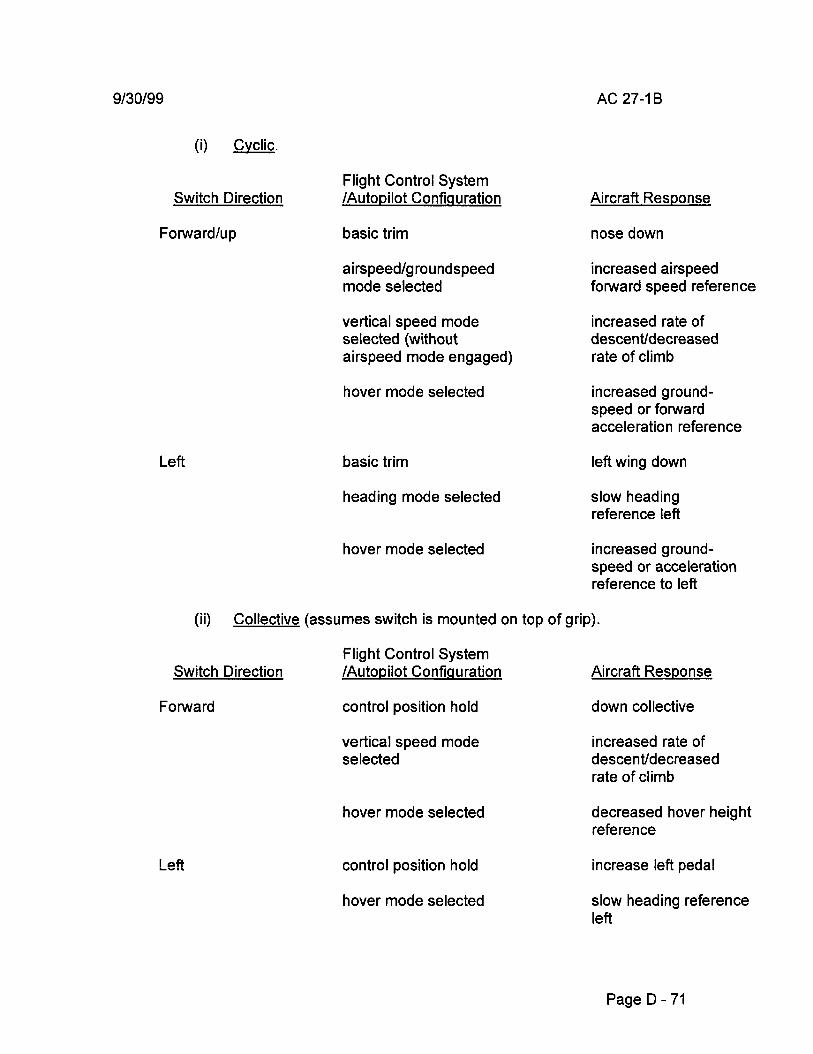
(i) Cyclic.
Switch Direction
Forward/up
Left
Flight Control System /Autopilot Configuration
basic trim
airspeed/groundspeed mode selected
vertical speed mode selected (without airspeed mode engaged)
hover mode selected
basic trim
heading mode selected
hover mode selected
AC 27-1 B
Aircraft Response
nose down
increased airspeed forward speed reference
increased rate of descent/decreased rate of climb
increased groundspeed or forward acceleration reference
left wing down
slow heading reference left
increased groundspeed or acceleration reference to left
(ii) Collective (assumes switch is mounted on top of grip).
Switch Direction
Forward
Left
Flight Control System /Autopilot Configuration
control position hold
vertical speed mode selected
hover mode selected
control position hold
hover mode selected
Aircraft Response
down collective
increased rate of descent/decreased rate of climb
decreased hover height reference
increase !eft pedal
slow heading reference left
PageD- 71

AC 27-1 B, Chg 3 9/30/2008
(iii) Opinions are divided concerning the preferred convention for forward and rearward motion of slew switches mounted atop the collective grip. Part of the reason appears to stem from the fact that such a switch is never used in a purely control position trim capacity. The switch has normally remained nonfunctional until a vertical autopilot mode is selected. At that point, the switch is viewed by one pilot/engineer contingent as either an autopilot reference slew function or a power increase/decrease switch which should follow the "forward equals increase" convention. The other group views the switch as a form of control position trim and finds the "forward equals down collective" convention to be more consistent with the sensing used for the cyclic beep switches. An obvious solution is to mount collective/vertical axis switches in a vertical orientation on the grip. Barring that alternative, viable arguments can be made for either philosophy. The recommended convention was selected following a survey of manufacturers and test pilots.
[The remainder of this page intentionally left blank.]
PageD- 72

9/30/2008 AC 27-18, Chg 3
[This page intentionally left blank.]
PageD- 72.1
AC 27-1 B, Chg 3 9/30/2008
AC 27.783. § 27.783 DOORS.
a. Explanation.
(1) Closed cabins must have at least one external door that is adequate and easily accessible for all of the occupants. The standard envisaged a door intended for normal use and for an emergency exit for all passengers. The passenger compartment, itself, should not be partitioned.
(2) Passenger doors should not be located near main or tail rotors such that persons using the door or doors would be endangered while entering or leaving the aircraft. The discs of engines or other propulsion system devices were not included in this standard. Procedures or instructions may be used to support compliance. Section 27.1565 concerns tail rotor markings.
(3) Cabin doors of normal category rotorcraft should inherently comply with the exit standards in§ 27.807(b) concerning the size of the unobstructed opening, accessibility, location, method of opening, arrangement, probable jamming due to fuselage deformation, and possibly markings inside and outside. The standards for the features and characteristics of exits should be applied to cabin doors unless an "exit" is also installed in the same side of the fuselage. The marking standards of§ 27.1557(d) for exits should be applied to doors unless the door is readily identified and its opening features are simple and obvious. It is not necessary to use red and white colors, provided the door instructions and markings are conspicuous.
(4) If the door is used as a "ditching exit," the threshold of the door/exit must be above the waterline of the rotorcraft while in calm water(§ 27.807(d)). Note that "ditching approval" under§ 27.801 is an optional standard.
(5) If a lock is used as an optional feature, the lock must not engage inadvertently or, as a result of mechanical failure, prevent possible opening of the door from inside or outside the cabin.
(6) If the door is a sliding door and intended to be opened and closed in flight, the sliding mechanism should positively attach the door to the airframe (e.g., sliding hinge) to minimize the likelihood of the door departing the aircraft in flight. Appropriate flight limitations should also be established to minimize any hazard while operating the door.
[The remainder of this page intentionally left blank.]
[Section AC 27.783 continued on the next page.]
PageD -72.2

9/30/2008 AC 27-1 B, Chg 3
AC 27.901A. § 27.901 (Amendment 27-23) INSTALLATION.
a. Explanation. Amendment 27-23 changes§ 27.901(b)(1) to require a satisfactory determination that the rotorcraft can operate safely throughout adverse environmental conditions such as high altitude and temperature extremes. This amendment was needed to provide consistent application of the environmental qualification aspects of the installation. This amendment also added a new paragraph (§ 27.901(b)(5)) to require design precautions to minimize the potential for incorrect assembly of components and equipment essential to safe operation.
b. Procedures. All of the policy material pertaining to this section remains in effect with the addition of design precautions. Design precautions should be taken to minimize the possibility of improper assembly of the components essential to the safe operation of the ratorcraft. Fluid lines, electrical connectors, control linkages, etc., should be designed so that they cannot be incorrectly assembled. This can be achieved by incorporating different sizes, lengths, and types of connectors, wires, fluid lines, and mounting methods. The applicant should perform a detailed maintenance assessment to clearly define the maintenance requirements, reliability, and serviceability of the drive system design. The applicant should consider all design qualification tests and service history data, if available. A review of accident data supports the importance of this assessment. Same applicants have utilized drive system vibration monitoring to verify continuing safe operation of their drive system.
[fhe remainder of this page intentionally left blank.]
Page E- 5

AC 27-1 B, Chg 3 9/30/2008
[This page left intentionally blank.]
Page E- 5.1

9/30/2008 AC 27-18, Chg 3
AC 27.903. § 27.903 (Amendment 27-11) ENGINES. [See new AC 27.903B (dated 9/17/2009) posted as separate document in RGL with this Master AC.]
a. Engine Type Certification.
(1) Explanation. Section 27.903(a) is intended to ensure that engines used in type certified aircraft are properly qualified and that the associated installation requirements are established.
(2) Procedures.
(i) Compliance can be documented by verification that a type certificate data sheet has been issued by the FAA/AUTHORITY for the engine identified by the rotorcraft manufacturer as the engine planned for use in the rotorcraft. Reciprocating engines must have been qualified to a special test plan(§ 33.49(d)) to be eligible in rotorcraft. This eligibility should be verified by a note on the engine type certificate data sheet.
(ii) On some occasions, the engine certification program is conducted concurrently With the rotorcraft certification program. This is technically acceptable provided the engine type certificate is issued prior to the rotorcraft type certificate. However, practical considerations involving the use of unapproved engine Installation data and the probability of engine design changes during the engine certification program that impact the rotorcraft certification program dictate that special procedures must be introduced to assure that the final rotorcraft certification program is satisfactory. If the engine under consideration is merely a minor model change from a previously certificated engine and these changes are unlikely to cause rotorcraft certification problems and do not involve significant installation aspects, the rotorcraft project engineer need only to follow the engine certification program by routine checks with the FAA/AUTHORITY office responsible for engine certification and, as a final pre-type certification item, verify that the engine type certificate has been issued. Rotorcraft Type Board agenda/minutes should reflect the ongoing status of the engine TC program. For rotorcraft certification programs involving new or significantly changed engines, the powerplant certification engineer for the rotorcraft should become as familiar with the engine as practicable with particular attention to engine ratings, limitations, performance, engine/rotorcraft interface aspects, and any Part 27 certification requirement involved in the engine program (fuel/oil filters, fuel heaters, integral firewalls, etc.) and establish an appropriate working arrangement With the FAA/AUTHORITY engine certification office to monitor changes in the engine certification progress which may impact the rotorcraft certification program. In addition, any rotorcraft certification activity such as test plans, analysis, compliance inspections, etc., which involves the engine should be accepted on a conditional basis; i.e., pending confirmation of completion of the engine program without changes pertinent to these aspects of rotorcraft program. The rotorcraft applicant should be advised of any limitations in this procedure, and that normally, the engine certification program should
Page E- 5.2

AC 27-1 B, Chg 3 9/30/2008
be complete before authorizing formal FAA/AUTHORITY participation in the rotorcraft certification plan; i.e., TIA.
b. Engine cooling fan protection.
(1) Explanation. Section 27.903(b) is intended to provide safety to the rotorcraft in the event of an assumed cooling fan blade failure or to prescribe a test to show that the cooling fan blade retention means is sufficient that blade failure is not a consideration.
(2) Procedures. The applicant may select§ 27.903(b)(1), (b)(2), or (b)(3) to show compliance with this section. If§ 27.903(b)(1) is selected, a demonstration should be conducted to show that at the maximum fan speed to be expected, a failed blade is contained within a housing or shroud which is included in the proposed type design and designated by the applicant as the containment shield. The rotational speed required may be related to an overspeed limiting device or to the maximum transient speed to be expected from analysis or test of the system or component which drives the fan. For components driven directly by the engine, output shaft disconnect and the subsequent terminal speed of the engine may set the test condition. To conduct an overspeed blade failure containment demonstration, applicants have found it convenient to progressively weaken a blade to induce failure at or above the required demonstration speed. Blade failure may be expected to subsequently fail some or all of the remaining blades. This condition, provided all blades are contained, is acceptable for showing compliance with this rule. However, the corresponding loss of cooling may be unacceptable if it causes the loss of any function essential to a controlled landing.
(3) Section 27.903(b)(2) may be selected; however, without containment, damage to any component or structure in the plane of the fan rotor or any other trajectory to be expected should not cause the loss of any function essential to a controlled landing.
[The remainder of this page intentionally left blank.]
[Section AC 27.903 continued on the next page.
Page E- 6

9/30/2008 AC 27-18, Chg 3
(2) Be easily removable for inspection of the magnetic poles for metallic chips; and,
(3) Prevent the loss of lubricant in the event of failure of the retention device for the removable portion of the chip detector (debris monitor).
[The remainder of this page intentionally left blank.]
Page F- 53

AC 27-18, Chg 3 9/30/2008
[This page intentionally left blank.]
Page F- 54

9/30/2008 AC 27-18, Chg 3
SUBPART F -EQUIPMENT
ELECTRICAL SYSTEMS AND EQUIPMENT
AC 27.1351. § 27.1351 (Amendment27-13) ELECTRICAL SYSTEMS AND EQUIPMENT-GENERAL
a. Explanation. With the advent of more sophisticated rotorcraft and operations under more critical conditions, such as JFR and icing, it is essential that the electrical system be very carefully analyzed and evaluated to assure proper operation under any foreseeable operating condrtion and that hazards do not result from any malfunctions or failures.
b. Procedures.
(1) Electrical System Capacity. Rotorcraft electrical systems have grown in capacrty, complexity, and impact on safety. This paragraph requires adequate electrical system capacity for safe operation of load circuits essential for safe operation at continuous rated power. If this capacity can be shown by electrical measurements, an electrical load analysis is not required. However, if the measurement method of compliance is chosen, data should be provided to show that the measured loads represent the worst case electrical loading for components or combination of components.
(i) Load circuits (systems) that are essential for safe operation are those systems necessary to maintain controlled flight and land safely and are generally those systems required to show compliance with the certification regulations. This includes most electrical utilization systems.
(ii) An electrical utilization system is a system of electrical equipment, devices, and connected wiring using electric energy to perform a specific aircraft function.
(iii) The specific utilization systems, which are necessary to maintain controlled flight and land safely, will vary with the type of rotorcraft and with the nature of operations. Examples of systems which may be essential are basic flight instruments, minimum navigation equipment, minimum radio communications, and flight control systems.
(2) Function.
(i) Generating systems should be analyzed, inspected, or tested to ensure that no probable malfunction in the generating system or in the generator drive system may cause loss of service to systems essential for safe operation. A probable malfunction is any single electrical or mechanical component malfunction or failure that
Page F- 55

AC 27-1 B, Chg 3 9/30/2008
is likely to occur based on past service experience. This past service experience can include malfunction of components of previously approved rotorcraft, other aircraft, or qualitative analysis of similar components in rotorcraft applications. Analyses should be performed on the electrical power system emphasizing the exclusion of single point failures and the possibility of latent failures. Test methods should be developed that uncover latent faults. To identify latent failure causing events, consider the functions and the results of the safety analysis, as well as any failure detection monitor that may be incorporated. Evaluate the system using various combinations of unforeseen internal signal patterns and states. Also, evaluate the non-monitored functions by selecting test conditions that use every signal path and decision point between the input and output. Refer to MG-2 for electrical system test methods. These analyses should be extended to multiple malfunctions when:
(A) The first malfunction would not be detected during normal operation of the system, including periodic checks established at intervals which are consistent with the degree of hazard involved; or
(B) The first malfunction would inevitably lead to other malfunctions.
(ii) The generator drive system includes the prime movers (propulsion engines or other) and coupling devices such as gearboxes or constant speed drives.
(iii) Where crew corrective action is necessary:
(A) Adequate warning should be provided for any malfunction or failure requiring such corrective action;
(B) Controls should be located to permit such corrective action during any probable flight situation;
(C) If corrective action must be taken within a specified time to continue safe operation of the generating system, it should be demonstrated that such corrective action can be accomplished within the specified time during any probable flight situation; and
(D) The procedure to be followed by the crew should be detailed in the Rotorcraft Flight Manual.
(iv) Chapter 11 of Advisory Circular 43.13-1A, "Acceptable Methods, Techniques, and Practices; Aircraft Inspection and Repair," includes guidance on installation of electrical systems (routing, separation, tying, clamping, j-box installations, etc.). Special emphasis should be placed on wire routing during the rotorcraft compliance inspection. Control wires to the rotorcraft's generators should be routed separately from generator output wiring. This should begin at the generator and continue to the voltage regulator. Additionally, wiring installation design should be
Page F- 55.1

9/30/2008 AC 27-18, Chg 3
documented sufficiently to maintain configuration control for manufacturing and to assure that the electromagnetic characteristics remain the same as the certification sample.
(3) Generating System. When electrical power is needed for essential equipment, this paragraph requires at least one generator with adequate capacity for safe operation. Complete electrical failures have been caused by loss of voltage control in the voltage regulator. Overvoltage conditions can destroy electronic equipment. An acceptable method of overvoltage protection is the use of a separate overvoltage sensing relay to trip the generator off the line when overvoltage is detected. Another acceptable method is use of a voltage regulator with built-in overvoltage protection.
(4) Generator Ratings: Generator ratings are often the result of installation temperature limitations. The determination of these limitations, if any, is by testing the actual installation. The procedures for performing generator cooling tests are as follows:
(i) Test Requirements.
(A) General. The applicant should contact the generator (alternator) manufacturer and obtain the maximum limits (continuous, 2 minute intermittent and 5 second transient maximum limits) for the unit to be tested. This will normally be in terms of temperatures at various locations within the unit (stator, bearings, diodes, heat sinks, brushes, etc.) or in terms of pressure drop across the generator. The manufacturer should either supply an instrumented unit or give complete details for instrumenting the test unit.
(B). Instrumentation.
ill Load Bank. A load bank will usually be necessary to load the test unit to the amperage limit for which approval is requested.
ill Ammeter. An ammeter should be provided with sufficient resolution to assure the amperage load is being maintained at the desired level.
.@) Temperature/Pressure Readouts. Readouts which are compatible with the temperature or pressure sensors installed in the test unit should be provided.
!i} Calibration Records. Calibration records should be available for all instrumentation.
@ Recordings. Permanent recordings shouid be provided for time, temperatures, current, and/or pressure. The recording device should have provisions for placing event marks on the recording medium.
Page F- 55.2
AC 27-18, Chg 3 9/30/2008
(C) Regulatory References. Sections 27.1301, 27.1309, 27.1351, 27.1521 (f), 27.1041, 27.1043, 27.1045 (through Amendment 27-19).
(D) Miscellaneous. The results obtained from the tests should be corrected for hot-day conditions using a standard lapse rate (3.6° F/1 ,000 feet). The tests are conducted to determine the maximum generator capacity that does not result in surpassing the limits given from the manufacturer. This is for a continuous rating, any credit for short time over current ratings must also be verified by the same methods, particularly for short time ratings longer than 5 seconds.
[The remainder of this page intentionally left blank.]
[Section AC 27.1351 continued on the next page.]
Page F- 56