advanced virgo technical design report vir{xxxa{12 · advanced virgo technical design report...
TRANSCRIPT

Advanced Virgo Technical Design Report
VIR–xxxA–12
Issue 1
The Virgo Collaboration
April 2, 2012


Contents
1 Interferometer Sensing and Control (ISC) 1
1.1 General description of the sub-system . . . . . . . . . . . . . . . . . . . . . . . . 1
1.2 Input from other subsystems and basic assumptions . . . . . . . . . . . . . . . . 2
1.3 Longitudinal control system: steady state control . . . . . . . . . . . . . . . . . . 3
1.3.1 Definition of degrees of freedom . . . . . . . . . . . . . . . . . . . . . . . . 4
1.3.2 Definition of available output ports and signals . . . . . . . . . . . . . . . 5
1.3.3 DC readout offset . . . . . . . . . . . . . . . . . . . . . . . . . . . . . . . 6
1.3.4 Accuracy requirements . . . . . . . . . . . . . . . . . . . . . . . . . . . . . 7
1.3.5 Consequences of the accuracy requirements on OMC filtering . . . . . . . 8
1.3.6 Design and performances of the control systems . . . . . . . . . . . . . . . 9
1.3.7 Requirements on modulation and demodulation noises . . . . . . . . . . . 10
1.3.8 ITF asymmetries and coupling of laser noises . . . . . . . . . . . . . . . . 13
1.3.9 Second stage of frequency stabilization . . . . . . . . . . . . . . . . . . . . 15
1.3.10 Input mirror Etalon tuning . . . . . . . . . . . . . . . . . . . . . . . . . . 20
1.4 Longitudinal control system: lock acquisition . . . . . . . . . . . . . . . . . . . . 20
1.4.1 Lock acquisition of the arm cavities . . . . . . . . . . . . . . . . . . . . . 20
1.4.2 Lock acquisition in power recycled configuration . . . . . . . . . . . . . . 21
1.4.3 Lock acquisition in dual-recycled configuration . . . . . . . . . . . . . . . 24
1.5 Auxiliary lasers . . . . . . . . . . . . . . . . . . . . . . . . . . . . . . . . . . . . . 24
1.5.1 Goals of the auxiliary lasers . . . . . . . . . . . . . . . . . . . . . . . . . . 24
1.5.2 Implementation and requirements . . . . . . . . . . . . . . . . . . . . . . 25
1.6 Sideband aberration risk reduction strategy . . . . . . . . . . . . . . . . . . . . . 26
1.7 Angular control system . . . . . . . . . . . . . . . . . . . . . . . . . . . . . . . . 27
1.7.1 Introduction . . . . . . . . . . . . . . . . . . . . . . . . . . . . . . . . . . 27
1.7.2 Radiation pressure effect and angular modes . . . . . . . . . . . . . . . . 27
1.7.3 Accuracy requirements . . . . . . . . . . . . . . . . . . . . . . . . . . . . . 29
1.7.4 Quadrants and demodulations . . . . . . . . . . . . . . . . . . . . . . . . 29
1.7.5 Automatic Alignment control scheme . . . . . . . . . . . . . . . . . . . . . 31
1.7.6 Performances of the angular control system . . . . . . . . . . . . . . . . . 33
1.7.7 Quadrant suspension requirements . . . . . . . . . . . . . . . . . . . . . . 33
1.8 Parametric instabilities . . . . . . . . . . . . . . . . . . . . . . . . . . . . . . . . . 37
1.9 Software requirements . . . . . . . . . . . . . . . . . . . . . . . . . . . . . . . . . 39
1.9.1 Fast realtime control . . . . . . . . . . . . . . . . . . . . . . . . . . . . . . 39
1.9.2 Slow control . . . . . . . . . . . . . . . . . . . . . . . . . . . . . . . . . . . 40
1.10 Interfaces with other subsystems . . . . . . . . . . . . . . . . . . . . . . . . . . . 41
1.10.1 OSD . . . . . . . . . . . . . . . . . . . . . . . . . . . . . . . . . . . . . . . 41
1.10.2 MIR . . . . . . . . . . . . . . . . . . . . . . . . . . . . . . . . . . . . . . . 41
1.10.3 INJ . . . . . . . . . . . . . . . . . . . . . . . . . . . . . . . . . . . . . . . 42
1.10.4 SBE . . . . . . . . . . . . . . . . . . . . . . . . . . . . . . . . . . . . . . . 42
1.10.5 DET . . . . . . . . . . . . . . . . . . . . . . . . . . . . . . . . . . . . . . . 43
3

1.10.6 PSL . . . . . . . . . . . . . . . . . . . . . . . . . . . . . . . . . . . . . . . 441.10.7 DAQ . . . . . . . . . . . . . . . . . . . . . . . . . . . . . . . . . . . . . . . 441.10.8 SAT . . . . . . . . . . . . . . . . . . . . . . . . . . . . . . . . . . . . . . . 441.10.9 PAY . . . . . . . . . . . . . . . . . . . . . . . . . . . . . . . . . . . . . . . 451.10.10 INF . . . . . . . . . . . . . . . . . . . . . . . . . . . . . . . . . . . . . . . 45
1.11 Summary and conclusions . . . . . . . . . . . . . . . . . . . . . . . . . . . . . . . 45

Chapter 1
Interferometer Sensing and Control(ISC)
1.1 General description of the sub-system
The Interferometer Sensing and Control (ISC) subsystem of the Advanced Virgo project dealswith the design of the control systems that will be used both during the lock acquisition of theinterferometer and the steady state (Science Mode) operations.
The design requirement to the ISC subsystem are:
Develop a control strategy capable of maintaining the interferometer controlled at thedesign sensitivity with good stability and duty cycle. This means that all control loopsmust have large enough stability margins and that all control noises re-introduced by theloops must contribute at maximum a factor 10 below the design sensitivity.
Develop a repeatable and robust lock acquisition strategy, capable of bringing the inter-ferometer from a fully uncontrolled state to the final, good sensitivity one in a reasonablyshort time (of the order of tens of minutes).
All of the above must be obtained for at least three different optical configurations: power-recycled only interferometer at low input power (chosen to be 25 W as reference); dual-recycled interferometer at low input power; dual-recycled interferometer at full input power(125 W).
The degrees of freedom to be controlled are divided in longitudinal and angular ones (refer tosec. 1.3.1 and 1.7.2 for definitions). Since the cross-coupling between the two sets is typicallynot dominant, the control system design can be carried out separately. In the longitudinal caseit is necessary to distinguish between the lock acquisition state and the steady state. In theangular control system case there is no need for such a distinction, since global control loops willbe activated only when the interferometer is already close enough to the final working point.
All the designs described in the following sections have been obtained using simulations of thefull interferometer based on modal models. The two main frequency-domain tools used so farare Finesse [1] and Optickle [2]. Both tools are to some extent incomplete: Finesse can introducehigher order modes but cannot deal with radiation pressure effects; on the other hand Opticklecan deal with radiation pressure but is limited to only the first higher order mode. Theselimitations are particularly relevant in the design of the angular control system.
Time-domain simulations were also used for the study of the lock acquisition procedures. The
1

Advanced Virgo TDR VIR–xxxxA–12
WE
WI
NENIBSPR
SR
OMC
B2
B1s
B1p
B1
B4
B8
B7
Figure 1.1: Optical layout of the Advanced Virgo interferometer, with mirrors and output portsnaming convention.
choice was to use the e2e [3] software, developed by the LIGO Scientific Collaboration, since itis well maintained and widely used for the design of Advanced LIGO lock acquisition.
Optical simulations of thermal effects and mirror defects inside the power recycling cavity (PRC)showed a large impact on radiofrequency sideband aberrations. A risk reduction strategy to haveerror signals less sensitive to PRC defects and aberrations is proposed. It will help in the firstcommissioning and locking steps (sec. 1.6).
1.2 Input from other subsystems and basic assumptions
All the main beams exiting from the interferometer (reflection, power recycling pickoff, darkport, transmission of the two arms) need to be probed with suitable photodiodes and quadrantphotodiodes for control and monitoring purposes. A scheme of the interferometer layout withthe naming convention is shown in Fig. 1.1.
The DET subsystem fixed the amount of power that can be sensed by each longitudinal photo-diode to 50 mW. DET plan to install two photodiodes per port under vacuum, to used in sciencemode. Therefore the longitudinal control design has been carried out considering that a total of100 mW is sensed with the longitudinal photodiodes. The total sensing noise is required to bedominated by the corresponding shot noise. In other words electronic noise in the photodiodeelectronic is considered to be negligible with respect to the shot noise [37, 38]. See sec. 1.3.6 formore details.
2

VIR–xxxxA–12 Advanced Virgo TDR
Similarly DET fixed the amount of power that can be sensed on each quadrant photodiode to25 mW for each port [5], except for the dark port before the output mode cleaner (OMC) wherethe power per quadrant is reduced to 2.5 mW to avoid losing too much of the main beam. Inthe control design the corresponding sensing noise is again required to be dominated by thecorresponding shot noise (sec. 1.7.6), thus considering other sources of noise (electronic andbench motion) to be negligible with respect to it.
The gravitation channel extraction foresee the use of a DC readout technique. It implies theaddition of an offset on one of the differential degrees of freedom to add a local oscillator carrierfield at the dark port. The amount of carrier power at the dark port was fixed by DET to be80 mW [40], based on considerations explained for example in [39].
A frontal modulation technique will be used to control all longitudinal degrees of freedom, exceptthe DARM one, and most of the angular degrees of freedom. Three modulation frequencies areforeseen in steady state conditions. Their values must be chosen, together with the optical pathlengths inside the interferometer, in order to meet the following requirements:
all modulation frequencies must be transmitted by the input mode cleaner (IMC);
the first two modulation frequencies must be resonant inside the PRC;
the third modulation frequency must be antiresonant inside the PRC;
the second modulation frequency must be resonant also inside the signal recycling cavity(SRC);
the transmission of the first modulation frequency to the dark port must be as small aspossible.
All these requirements constrain the possible frequencies and distances between mirrors. Con-sidering also the requirements coming from infrastructure and vacuum the set of lengths andmodulation listed in the OSD chapter are obtained (sec. [OSD chapter] and Tab. 1.1).
The present design of the INJ subsystem foresee the ability of delivering a modulation index of0.1 for all main modulation frequencies.
The longitudinal and angular control system have been designed starting from the assumptionthat the mirror residual motions at low frequency will be of the same order of magnitude ofthose obtained in Virgo: about 0.5 µm and 0.1 µrad RMS concentrated below few Hz.
The Advanced Virgo detector in dual recycled configuration is expected to work with differenttunings of the SRC. In the design of both angular and longitudinal control systems only the onewhich optimizes the sensitivity for NS-NS inspirals has been considered. The SRC tuning willbe controlled changing the offset added to the signal recycling cavity length (SRCL) error signal.The available linear range is about double of the tuning corresponding to the NS-NS-optimizedconfigurations. The effect of using different tunings on the control loops and on noise couplingshas not been studied yet.
1.3 Longitudinal control system: steady state control
The optical response of the interferometer to longitudinal motions of the mirrors has been simu-lated using Optickle [2] which is as of today the only tool capable of including radiation pressureeffects. Three different configurations have been considered for all the design steps: power-recycled only interferometer at low input power, namely 25 W; dual recycled interferometer atlow input power (25 W); dual recycled interferometer at full input power, namely 125 W.
3

Advanced Virgo TDR VIR–xxxxA–12
Parameter Value
Power recycling mirror transmission 0.05Input mirror transmission 0.014End mirror transmission 1 ppmSignal recycling mirror transmission 0.2Losses per mirror 32.5 ppmArm cavity mirror mass 42 kgPower recycling cavity length 11.952 mSignal recycling cavity length 11.952 mSchnupp asymmetry 0.23 mArm cavity length 2999.8 mModulation frequencies f1 = 6270777 Hz
f2 = 56436993 Hzf3 = 8361032 Hz
Suspension last stage resonant frequency 600 mHzDC readout offset see Tab. 1.3Signal recycling cavity detuning 3.022× 10⁻⁷ m
Table 1.1: List of relevant parameters used in the Optickle simulation. Reference from [8].
Mirror/DOF DARM CARM MICH PRCL SRCL
NE −1/2 −1WE 1/2 −1BS 1/
√2
PR −1/2 −1SR 1/2 −1
Table 1.2: Driving coefficients for dual recycled interferometer. In the case of power recycled onlyinterferometer the SR driving is simply removed.
The main parameters used in the simulation are summarized in Tab. 1.1. More details on thelongitudinal control can be found in the note [6].
1.3.1 Definition of degrees of freedom
In a dual recycled interferometer the length sensing and control system deals with five degrees offreedom. Referring to Fig. 1.2, the microscopic positions (tunings) of all mirrors are combinedto obtain the following physical degrees of freedom:
DARM =LN − LW
2
CARM =LN + LW
2MICH = lN − lW
PRCL = lP +lN + lW
2
SRCL = lS +lN + lW
2
The simplest extension of Virgo driving to Advanced Virgo consists in controlling MICH / PRCL/ SRCL using PR / SR / BS. Table 1.2 summarizes the driving matrix for a dual recycledinterferometer as it is used in all the following simulations.
4

VIR–xxxxA–12 Advanced Virgo TDR
BS NI NE
WI
WE
PRM
SRM
LW
LNlN
WI
lW
lP lS
Figure 1.2: Scheme of relevant physical distances between mirrors in a dual recycled interferometer.
In addition to these “mechanical” degrees of freedom one should consider the laser frequencystabilization loop, which locks the laser to the mean length of the two arm cavities with typicalbandwidths of few tens of kHz (sec. 1.3.9). The laser frequency will follow the motion of thearm cavity mean length, called CARM in the previous equations. The typical motion of theCARM degree of freedom, if left free, would correspond to thousands of Hz. To avoid such largefluctuation the CARM mechanical mode will be controlled, acting on the end mirrors, using anerror signal coming from the reference cavity [18]. This is the same strategy adopted in Virgo+and allowed also to extract complete position information to be used for the Global InvertedPendulum Control (GIPC) system.
1.3.2 Definition of available output ports and signals
There are many output ports foreseen in Advanced Virgo:
The dark fringe or asymmetric port: before the OMC a small fraction is extracted andsent to B1p. The transmission of the OMC is B1 and the reflection is B1s. Since the OMCshould filter all sidebands, B1 contains only the fundamental mode carrier field, while allhigher order modes and sidebands should therefore go in B1s. For steady state longitudinalcontrol only B1 is used.
The interferometer reflection or symmetric port, named B2. The amount of power availablein this port depends largely on the impedance matching between the PR mirror and thearm cavities reflectivities, which is in turn determined by their round trip losses.
The transmission of the two arm cavities, named B7 and B8 for north and west respectively.They will not be used for the longitudinal steady state control.
The power recycling cavity pickoff port (B4), which will be extracted using a plate in frontof the power recycling mirror.
5

Advanced Virgo TDR VIR–xxxxA–12
The beam is frontal modulated at three radio frequencies listed in Tab. 1.1, using electro-opticalmodulators placed before the input mode cleaner, with modulation indexes set to 0.1. Thefrequencies must therefore be multiples of the IMC free spectral range. Not all the possibledemodulated signals will be needed at all ports: the B1 beam will not see any sideband, sodemodulation is useless on that port; f3 is antiresonant in the recycling cavity, so signals de-modulated at this frequency will be useful only in the B2 beam; the B4 beam finally will containboth f1 and f2 sidebands and will provide useful signals at both demodulations. The nameconvention for signals is: PORT SBx yy where x refer to the modulation frequency and canrange from 1 to 3, while yy can be DC, P or Q referring respectively to power signal, demod-ulated in-phase and demodulated quadrature channels. Demodulation phase is chosen in eachconfiguration in order to maximize one chosen degree of freedom in P over Q. Details are givenfor each configuration separately.
The total power which is sensed at each longitudinal photodiode is 100 mW, according to specifi-cations given by the DET subsystem [5]. All signals are considered limited by the correspondingshot noise, meaning that all sources of electronic noise are required to be negligible.
The reflectivity of the power recycling pick-off plate (POP) was chosen to be 300 ppm. This willprovide 100 mW for the longitudinal photodiodes and 50 mW for the quadrant diodes for inputpower larger than 14 W. In this way it will be possible to fully exploit the shotnoise limitedsensitivity since the first commissioning steps.
1.3.3 DC readout offset
The DC-readout scheme foresees the addition of an offset to a differential degree of freedom,in order to have a static carrier field reaching the dark port, to be used as phase reference forhomodyne detection. In principle it is possible to generate such a static field both with an offsetin DARM or MICH. The use of a DARM offset introduces a detuning of the arm cavities fromresonance, thus in principle increasing the influence of radiation pressure. Instead using a MICHoffset does not move the arm cavities out of resonance. In the presence of a SRC the distinctionis however not straightforward. One important point is how optical transfer functions changewith the offset, in particular the DARM one and the power and frequency noise couplings.
Results detailed in [6] show that the behavior is different in power recycled and dual recycledconfiguration. In power recycled only case, if the offset is added to MICH instead of DARM, thereis no more any effect of radiation pressure in the DARM optical transfer function. Moreover,in the case of MICH offset, the coupling of frequency and power noises to the output signal islower, at least in the more critical low frequency region. Therefore the use of a MICH offset ispreferable in the case of power recycled only interferometer.
The situation is different in the dual recycled case. Since the DARM optical transfer functionis dominated by radiation pressure effects due to the SRC, there is no difference wherever theoffset is added. Frequency and power noises instead couple more if a MICH offset is used. It isthen preferable to use a DARM offset in the dual recycled case.
In conclusion, in the following simulations, a MICH offset is used in the power recycled interfer-ometer and a DARM one in the dual recycled case. In all three configuration the offset is tunedin order to have 80 mW of carrier fundamental mode power at the dark port. The resultingoffsets are summarized in Tab. 1.3.
Moreover, the value of the differential offset (on MICH or DARM) has a strong influence on theangular sensing matrix: the larger the offset, the less diagonal the sensing matrix. Thereforethe value of the offset should be maintained as small as possible to improve the angular controlsystem robustness [9].
6

VIR–xxxxA–12 Advanced Virgo TDR
Configuration degree of freedom (DOF) Offset [m]
Power recycled 25W MICH 1.6 · 10−9
Dual recycled 25W DARM 2.3 · 10−11
Dual recycled 125W DARM 1.0 · 10−11
Table 1.3: Offsets needed for reaching 80 mW of power at dark port.
DOF Power rec. 25W Dual rec. 25W Dual rec. 125W
DARM 6 · 10−16 m 2 · 10−15 m 1 · 10−15 mFrequency 7 mHz
CARM 4 · 10−13 mMICH 2 · 10−13 m 6 · 10−13 m 3 · 10−13 mPRCL 2× 10⁻¹¹ mSRCL 3 · 10−13 m
Table 1.4: Summary of accuracy requirements for longitudinal control loops.
1.3.4 Accuracy requirements
The accuracy requirements for longitudinal loops are summarized in Tab. 1.4. The reasoningused to derive these numbers is explained in the note [6]. Here only the considerations for DARMand CARM are repeated, since these accuracy requirements are those having stronger impactson interfaces with other subsystems.
In the DARM case the most stringent requirement comes from the use of DC readout. Indeedthe response of the dark fringe power to differential motion is intrinsically non linear: the DCpower at B1 varies with very good approximation as a parabola centered at zero offset. Theoptical gain is given by the derivative of this parabola and therefore it varies linearly even aroundthe nominal operating point.
In general the power at dark port can be described by the following equation:
B1 = b0 + αδz + βδz2 (1.1)
where δz is the residual motion of DARM. The coefficients α and β can be obtained fromsimulations. However their dependence on the DC readout offset is easily computed, consideringthe quadratic nature of the B1 power response to DARM motion: β is constant and α = 2z0βwhere z0 is the static offset.
One of the effects of the non linear term in the above equation is to create up-conversion of lowfrequency residual DARM motion around high frequency lines. Indeed, the previous equation iscorrect in the time domain:
b(t) = b0 + αδz(t) + βδz(t)2 (1.2)
which in frequency domain becomes:
b(f) = αδz(f) + β(δz ? δz)(f) (1.3)
If we assume the DARM motion to be composed of a low frequency part (residual motion) andof a large spectral line (like for example violin modes) the convolution can be easily computedand the signal on the diode at the line frequency will be
b(f) = αzL
(1 +
2β
αzRMS
)δ(f − fL) (1.4)
where zL and fL are the amplitude and frequency of the line and zRMS is the residual DARMmotion. The second term inside the brackets gives the level of low frequency up-converted noise
7
Advanced Virgo TDR VIR–xxxxA–12
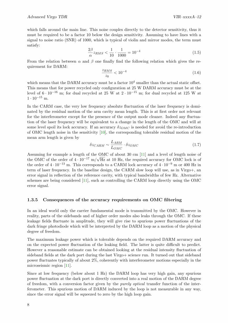
which falls around the main line. This noise couples directly to the detector sensitivity, thus itmust be required to be a factor 10 below the design sensitivity. Assuming to have lines with asignal to noise ratio (SNR) of 1000, which is typical of violin and mirror modes, the term mustsatisfy:
2β
αzRMS <
1
10· 1
1000= 10−4 (1.5)
From the relation between α and β one finally find the following relation which gives the re-quirement for DARM:
zRMS
z0< 10−4 (1.6)
which means that the DARM accuracy must be a factor 104 smaller than the actual static offset.This means that for power recycled only configuration at 25 W DARM accuracy must be at thelevel of 6 · 10−16 m; for dual recycled at 25 W at 2 · 10−15 m; for dual recycled at 125 W at1 · 10−15 m.
In the CARM case, the very low frequency absolute fluctuation of the laser frequency is domi-nated by the residual motion of the arm cavity mean length. This is at first order not relevantfor the interferometer except for the presence of the output mode cleaner. Indeed any fluctua-tion of the laser frequency will be equivalent to a change in the length of the OMC and will atsome level spoil its lock accuracy. If an accuracy δzOMC is needed for avoid the re-introductionof OMC length noise in the sensitivity [10], the corresponding tolerable residual motion of themean arm length is given by
δzCARM ∼LARMLOMC
· δzOMC (1.7)
Assuming for example a length of the OMC of about 30 cm [11] and a level of length noise ofthe OMC of the order of 4 · 10−17 m/
√Hz at 10 Hz, the required accuracy for OMC lock is of
the order of 4 · 10−13 m. This corresponds to a CARM lock accuracy of 4 · 10−9 m or 400 Hz interm of laser frequency. In the baseline design, the CARM slow loop will use, as in Virgo+, anerror signal in reflection of the reference cavity, with typical bandwidths of few Hz. Alternativeschemes are being considered [11], such as controlling the CARM loop directly using the OMCerror signal.
1.3.5 Consequences of the accuracy requirements on OMC filtering
In an ideal world only the carrier fundamental mode is transmitted by the OMC. However inreality, parts of the sidebands and of higher order modes also leaks through the OMC. If theseleakage fields fluctuate in amplitude, they will give rise to spurious power fluctuations of thedark fringe photodiode which will be interpreted by the DARM loop as a motion of the physicaldegree of freedom.
The maximum leakage power which is tolerable depends on the required DARM accuracy andon the expected power fluctuation of the leaking field. The latter is quite difficult to predict.However a reasonable estimate can be obtained looking at the residual intensity fluctuation ofsideband fields at the dark port during the last Virgo+ science run. It turned out that sidebandpower fluctuates typically of about 2%, coherently with interferometer motions especially in themicroseismic region [11].
Since at low frequency (below about 1 Hz) the DARM loop has very high gain, any spuriouspower fluctuation at the dark port is directly converted into a real motion of the DARM degreeof freedom, with a conversion factor given by the purely optical transfer function of the inter-ferometer. This spurious motion of DARM induced by the loop is not measurable in any way,since the error signal will be squeezed to zero by the high loop gain.
8

VIR–xxxxA–12 Advanced Virgo TDR
Configuration Optical gain (G) Requirements
Power recycled 25W 2.8 · 1010W/m 0.08 mWDual recycled 25W 7 · 109W/m 0.07 mWDual recycled 125W 1.5 · 109W/m 0.08 mW
Table 1.5: Requirement on spurious field transmission through the OMC, assuming a residualintensity noise of 2%.
The word purely optical in the last paragraph is relevant in a radiation pressure dominatedregime. Radiation pressure creates an optomechanical modification of the transfer function.Any force applied to the DARM degree of freedom creates a potential displacement of the samedegree of freedom. This in turn modulates the field inside the arms and induces an additionalforce on DARM via radiation pressure. The net effect is a reduced real motion of the degreeof freedom. However, once the real displacement is properly computed, taking into accountthe depressing factor due to radiation pressure, the dark fringe power signal responds with atransfer function which depends only on the optics and corresponds to what one would get fromcomputations which do not include radiation pressure.
The spurious DARM motion induced by a leakage field residual intensity noise is given by
δDARM =PsRINs
G(1.8)
where G is the optical gain of dark fringe with respect to DARM; PS is the total power of theleaking field and RINS is the corresponding residual intensity noise.
To properly control the DARM loop at the level of accuracy δzRMS considered in the previoussection, the contribution of spurious motion due to leaking field must be well below this level. Ifwe ask this contribution to sum up to less than 10% of the needed accuracy, the limit on leakingfield is given by:
PS <1
10· δzRMSG
RINS(1.9)
The resulting requirements on leaking power in transmission of the dark fringe are summarizedin Tab. 1.5 as a function of the interferometer configuration.
1.3.6 Design and performances of the control systems
The detailed iterative procedure to design a control scheme compatible with both the accuracyrequirements and the noise re-introduction requirements is described in [6]. In each differentconfiguration and for each degree of freedom, the error signal with highest signal-to-(shot)noiseratio has been selected and the corresponding demodulation phase tuned, see Tab. 1.6.
To reduce the coupling of sensing noise to detector sensitivity below the safety factor, it wasnecessary to assume the implementation of noise subtraction paths [12] with performances ofthe order of a factor 500 of coupling reduction. This level is the one obtained in Virgo+ and itis considered feasible.
Moreover, during the control loop design it turned out that to achieve the desired accuracy it isnecessary to properly diagonalize the sensing matrix. The precision needed for such diagonal-ization ranges from 10% in the power recycled case to fractions of 1% in the dual recycled case,which is a quite difficult performance to achieve. More investigations in this direction will beneeded, in particular to assess the need of adaptive diagonalization of the sensing matrix. Verysimple matrix diagonalization servos were already implemented in Virgo at the time of the firstcommissioning runs.
9

Advanced Virgo TDR VIR–xxxxA–12
The performances in terms of accuracy are listed in Tab. 1.6.
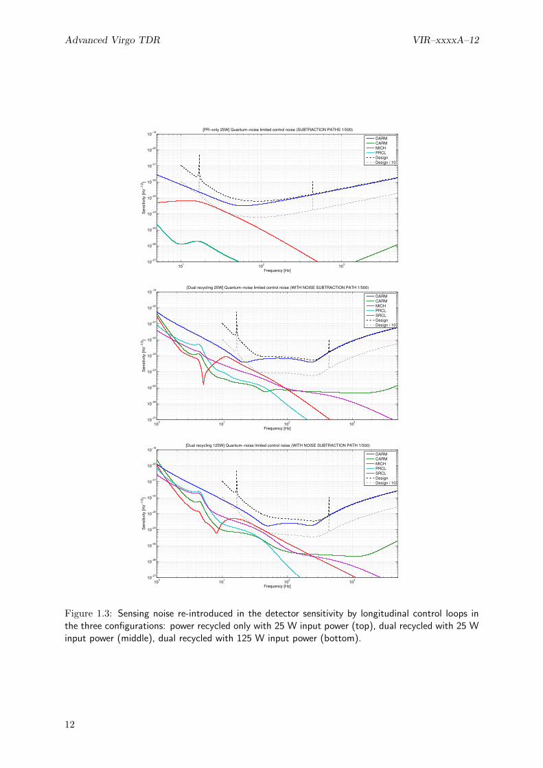
The level of control noise which is coupled to the detector sensitivity in the three configurationsis shown in Fig. 1.3. The level of sensing noise is the one corresponding to shotnoise-limitedsensitivity for 100 mW of total sensed power per auxiliary port. In all the configurations theMICH degree of freedom is the most critical and its control noise is at the limit of the factor 10below design sensitivity.
The filter optimization is a balance between having high gain below 2-3 Hz to be able to reachthe accuracy requirements and string enough roll-off at higher frequencies (above 10 Hz) to avoidre-introducing control noise in the detector sensitivity. The stability of the control loop imposessome limits on the possible optimization. The present design is barely fulfilling the requirementswith the minimum acceptable stability margins (30 degree of phase margin and less than a factor2 of gain margin). Further optimizations of the present scheme are very difficult. Any increaseof the sensing noise or of the payload motion would result in the longitudinal control being nomore complaint with the design.
Another critical point is the implementation of the DARM loop in the dual recycled case. Indeedin this case the DARM opto-mechanical transfer function contains an unstable pole at some tensof Hz (the frequency is proportional to the input power). To stabilize the system it is thereforenecessary to have a much larger bandwidth than in the Virgo+ case. The present design foreseesa unity gain frequency of about 400 Hz, which is necessary to stabilize the system with suitablegain and phase margins and reach the required accuracy. The need of significantly increase thebandwidth of the DARM loop has strong consequences on the design of the real-time controlsystem and of the payload. Indeed, the present design of the DARM loop is compatible with atotal delay in the control chain of 50 µs (assuming the phase margin must be larger of 30 degrees).This seems very difficult to achieve. On the payload design side, the structure that will holdthe coils used to apply the control forces should not have structural resonances inside the activebandwidth of the loop, otherwise they could get too excited by the control itself. Having allstructural resonances above 400 Hz seems very difficult. Both DAQ and PAY considerationstriggered the need of a more deep study of the DARM control. It seems feasible to reduce thebandwidth to 200 Hz, even if a detailed design is not available yet. In this way the total delayrequirement would be relaxed to 100 µs and the resonance requirement to 200 Hz.
More details on the final control system design are available in the note [6].
1.3.7 Requirements on modulation and demodulation noises
The main gravitational channel is extracted using DC readout, therefore it is not affected byradiofrequency sideband noises, provided the OMC filtering is adequate. However all the signalsused for the auxiliary degrees of freedom control are obtained with a standard demodulationtechnique. Therefore any phase or amplitude noise of the radiofrequency sidebands will pollutethese signals.
The coupling of phase and amplitude noise can be modeled with good accuracy as a crossquadrature coupling [13]. If the Q quadrature of a signal is not perfectly zero, due to an offsetor to residual RMS motion, it induces a coupling of phase noise to the P quadrature. A similarcoupling exists for the sideband amplitude noise, this time coupling each quadrature with itsown RMS motion. The two couplings can be described using the following equations:
nP (f) = δQRMS φ(f) (1.10)
nP (f) = δPRMSδA(f)
A(1.11)
10

VIR–xxxxA–12 Advanced Virgo TDR
Power recycled only at 25 W
D.O.F. Error signal Accuracy Requirement
DARM B1 DC 5 · 10−16 m 6 · 10−16 mFrequency B2 SB1 P 0.6 mHz 7 mHz
MICH B4 SB1 Q 1.3 · 10−13 m 2 · 10−13 mPRCL B2 SB3 P 2× 10⁻¹² m 2× 10⁻¹¹ m
Dual recycled at 25 W
DOF Error signal Accuracy Requirement
DARM B1 DC 1.1 · 10−15 m 1 · 10−15 mFrequency B2 SB3 P 0.05 mHz 7 mHz
MICH B4 SB2 Q 1.8 · 10−12 m 2 · 10−12 mPRCL B2 SB1 P 1× 10⁻¹³ m 2× 10⁻¹¹ mSRCL B4 SB2 P 3× 10⁻¹⁴ m 2× 10⁻¹² m
Dual recycled at 125 W
DOF Error signal Accuracy Requirement
DARM B1 DC 6 · 10−16 m 1 · 10−15 mFrequency B2 SB3 P 0.09 mHz 7 mHz
MICH B4 SB2 Q 2.4 · 10−14 m 2 · 10−12 mPRCL B2 SB1 P 1× 10⁻¹⁴ m 2× 10⁻¹¹ mSRCL B4 SB2 P 3× 10⁻¹⁵ m 2× 10⁻¹² m
Table 1.6: Summary of error signals and obtained accuracies in: power recycled configuration at25 W input power (top), dual recycled at 25 W (middle), dual recycled at 25 W (bottom).
11
Advanced Virgo TDR VIR–xxxxA–12
101
102
103
10−27
10−26
10−25
10−24
10−23
10−22
10−21
10−20
10−19
Frequency [Hz]
Sensitiv
ity [H
z−
1/2
]
[PR−only 25W] Quantum−noise limited control noise (SUBTRACTION PATHS 1/500)
DARM
CARM
MICH
PRCL
Design
Design / 10
100
101
102
103
10−27
10−26
10−25
10−24
10−23
10−22
10−21
10−20
10−19
Frequency [Hz]
Sensitiv
ity [H
z−
1/2
]
[Dual recycling 25W] Quantum−noise limited control noise (WITH NOISE SUBTRACTION PATH 1/500)
DARM
CARM
MICH
PRCL
SRCL
Design
Design / 10
100
101
102
103
10−27
10−26
10−25
10−24
10−23
10−22
10−21
10−20
10−19
Frequency [Hz]
Sensitiv
ity [H
z−
1/2
]
[Dual recycling 125W] Quantum−noise limited control noise (WITH NOISE SUBTRACTION PATH 1/500)
DARM
CARM
MICH
PRCL
SRCL
Design
Design / 10
Figure 1.3: Sensing noise re-introduced in the detector sensitivity by longitudinal control loops inthe three configurations: power recycled only with 25 W input power (top), dual recycled with 25 Winput power (middle), dual recycled with 125 W input power (bottom).
12

VIR–xxxxA–12 Advanced Virgo TDR
Frequency Phase noise [rad/√
Hz] Rel. ampl. noise [1/√
Hz]
6.3 MHz 1.8 · 10−6 1.7 · 10−7
56.4 MHz 1.1 · 10−6 1.1 · 10−6
8.4 MHz 0.27 1.7 · 10−7
Table 1.7: Summary of requirements for sideband amplitude and phase noise. Modulation noisesenters in the photodiode output signal following two paths. The first one is through the noise at thelevel of the modulation, which is transmitted to the laser beam and enters on one of the inputs ofthe mixer. The second path is through noise introduced by the local oscillator distribution system,which enters on the other input of the mixer. The requirements given here apply to the total of thetwo contributions.
where φ(f) is the spectrum of the phase noise measured in rad/√
Hz, δA(f)A is the residual
amplitude noise of the sideband at the given frequency measured in 1/√
Hz, δPRMS , and δQRMS
are the residual motion or offset in the P or Q quadrature. Finally nP (f) is the resulting noiseinto the P quadrature. Similar equations hold for the other quadrature.
From the simulations described in the previous sections, the obtained loop accuracy can betranslated in residual RMS signals in each port quadrature. Asking the sideband phase andamplitude noise to be a factor 10 below the shot noise, one can obtain requirements on the totalmodulation and demodulation noises at the mixer input. Results are summarized in Tab. 1.7,quoting only the most stringent requirement for each frequency, regardless of the interferom-eter configuration. Refer to [INJ chapter, section 1.6.4] for a comparison with the expectedperformances.
1.3.8 ITF asymmetries and coupling of laser noises
In order to assess requirements for power and frequency noises, Optickle was used to simulateAdvanced Virgo interferometer in two configurations: power recycled at 25 W and dual recycledat 125 W.
As well known, Optickle has some limitations, in particular it cannot deal with higher ordermodes other than the first one, so it cannot be used to evaluate the effect of geometrical asym-metries such as arm length and/or radius of curvature mismatch, and it cannot even handlefigure error maps for the core optics. On the other hand, it is possible to include radiation pres-sure effects and mechanical transfer functions, that are important at low frequency. Simulationswere then carried out in order to evaluate the effects of loss and finesse asymmetries on thecoupling of laser power and frequency noises to the dark fringe and the impact on AdvancedVirgo sensitivity. Although possible, no control loops were included in the simulation so to speedup calculations.
Power recycled configuration at 25 W
Starting from a situation without any defect, finesse and loss asymmetries were introduced oneat a time and together [14, 15]. Frequency noise requirements are reported in Fig. 1.4 bothfor the no defect case and for some values of finesse and loss asymmetries. Without SRC andwithout any defect, the requirements for frequency noise are much more relaxed with respect tothe dual recycled configuration, but they worsen very quickly as soon as defects are introducedin the simulation. For this configuration loss asymmetry is the worst offender at high frequency,and finesse asymmetry at intermediate frequency.
13

Advanced Virgo TDR VIR–xxxxA–12
101
102
103
10−7
10−6
10−5
10−4
10−3
10−2
10−1
freq [Hz]
[Hz /
Hz
1/2
]
Frequency noise requirement
no defects
dP = +50ppm; dF/F = −0.02
dP = −50ppm; dF/F = −0.02
dP = −50ppm; dF/F = +0.02
dP = +50ppm; dF/F = +0.02
dP = +20ppm; dF/F = +0.01
dP = +50ppm; dF/F = +0.01
101
102
103
10−8
10−7
10−6
10−5
freq [Hz]
[RIN
/ H
z1/2
]
Power noise requirement
no defects
dP = +50ppm; dF/F = −0.02
dP = −50ppm; dF/F = −0.02
dP = −50ppm; dF/F = +0.02
dP = +50ppm; dF/F = +0.02
dP = +20ppm; dF/F = +0.01
dP = +50ppm; dF/F = +0.01
Figure 1.4: Laser and frequency noise requirements for power recycled at 25 W configuration, asafety factor of ten has been used to draw the requirements from nominal sensitivity. Differentvalues of finesse and loss asymmetries have been used. Top: laser frequency noise at interferometerinput. Bottom: laser intensity noise at interferometer input.
14
VIR–xxxxA–12 Advanced Virgo TDR
The situation is more complicated for the power noise requirements (see Fig. 1.4), as for thecoupling to the detector sensitivity also the sign of the asymmetries plays a role, but in generalwe have almost a factor 10 less coupling for power recycled only with respect to dual recycled.
Dual recycled configuration at 125 W
Starting from a situation without any defect, finesse and loss asymmetries were introduced oneat a time and together [14, 15]. It turned out that loss asymmetry is the worst offender athigh frequency (see top plots of Fig. 1.5 and 1.6), while finesse asymmetry plays more a roleat intermediate frequency (see bottom plots of 1.5 and 1.6), for the coupling of laser power andfrequency noises to DARM. One important thing to notice in those plots is that asymmetriesare not symmetrical: the sign does play a role in shaping the coupling of laser noises to DARM,depending on the sign set to the DARM offset, and this could make choosing the sign of thisoffset a bit tricky, as a situation could occur where the signs of asymmetries require contradictoryoptimizations with respect to DARM offset sign. Based on those simulations, requirements oninput technical noises are drawn considering several combinations of signs for the aforementionedasymmetries (see Fig.1.7, and files attached to [15]).
Triggered by a proposal put forward by DET subsystem [16], frequency and power noise couplingsare also recomputed with an increased offset on DARM degree of freedom. The aim was tocheck whether doubling the offset would have had a negative impact on those noise couplings,but as far as only finesse and loss asymmetries are concerned (no other defects introduced in thesimulation), there are no dramatic changes in frequency and power noise couplings to sensitivity.
1.3.9 Second stage of frequency stabilization
The second stage of frequency stabilization (SSFS) is used to lock the laser frequency to the armcavity mean length. It is necessary to meet the requirement on residual frequency noise detailedin sec. 1.3.8. The control architecture is the same as in the Virgo+ case: the correction computedby the SSFS controller is added to the error signal of the laser frequency pre-stabilization andsimultaneously used for the lock of the input mode cleaner [17]. The error signal which will beused is always extracted from the interferometer reflection, demodulated at f1 or f3 dependingon the optical configuration.
The unity gain frequency of the SSFS loop is expected to be at about 20-30 kHz, the upper limitset by the arm cavity free spectral range notch. Controllers with such a high bandwidth areeasily built using analog electronic, as done in Virgo+. However it is known that the shape ofthe interferometer optical transfer function between 3 and 50 kHz depends strongly on sidebandsaberrations. The possibility of using an ad-hoc digital control system with high sampling rateis being investigated. This would provide the needed flexibility to cope with changes in theoptical transfer functions, without the need of rebuilding the analog electronics every time theinterferometer behavior changes.
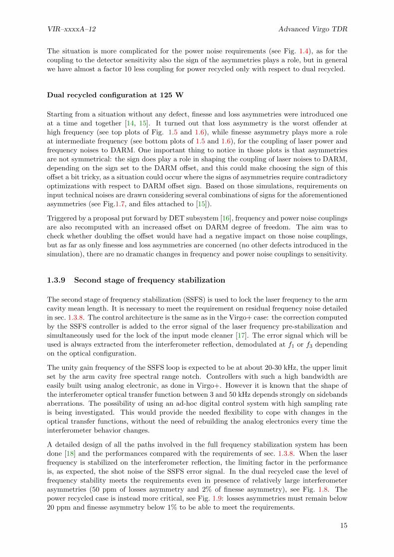
A detailed design of all the paths involved in the full frequency stabilization system has beendone [18] and the performances compared with the requirements of sec. 1.3.8. When the laserfrequency is stabilized on the interferometer reflection, the limiting factor in the performanceis, as expected, the shot noise of the SSFS error signal. In the dual recycled case the level offrequency stability meets the requirements even in presence of relatively large interferometerasymmetries (50 ppm of losses asymmetry and 2% of finesse asymmetry), see Fig. 1.8. Thepower recycled case is instead more critical, see Fig. 1.9: losses asymmetries must remain below20 ppm and finesse asymmetry below 1% to be able to meet the requirements.
15

Advanced Virgo TDR VIR–xxxxA–12
101
102
103
10−7
10−6
10−5
10−4
10−3
10−2
10−1
[m /
m]
[Hz]
Frequency noise coupling dF/F =0
dP = 0
dP = +40ppm
dP = −40ppm
dP = +60ppm
dP = −60ppm
101
102
103
10−14
10−13
10−12
10−11
10−10
10−9
[m]
[Hz]
Power noise coupling dF/F =0
dP = 0
dP = +40ppm
dP = −40ppm
dP = +60ppm
dP = −60ppm
Figure 1.5: Dual recycled at full power configuration. Transfer functions in case of equal finesse(F = 443) as a function of round trip loss asymmetry. Average round trip losses are 75 ppm. Top:frequency noise transfer function. Bottom: power noise transfer function.
16

VIR–xxxxA–12 Advanced Virgo TDR
101
102
103
10−6
10−5
10−4
10−3
10−2
10−1
100
[m /
m]
[Hz]
Frequency noise coupling dP =0
dF/F =0
dF/F = −0.02
dF/F = +0.02
dF/F = −0.04
dF/F = +0.04
101
102
103
10−14
10−13
10−12
10−11
10−10
10−9
[m]
[Hz]
Power noise coupling dP =0
dF/F =0
dF/F = −0.02
dF/F = +0.02
dF/F = −0.04
dF/F = +0.04
Figure 1.6: Dual recycled at full power configuration. Transfer functions in case of equal round triplosses (RTL = 75 ppm) as a function of finesse asymmetry. Average finesse is 443. Top: frequencynoise transfer function. Bottom: power noise transfer function.
17

Advanced Virgo TDR VIR–xxxxA–12
101
102
103
10−7
10−6
10−5
10−4
10−3
10−2
freq [Hz]
[Hz /
Hz
1/2
]
Frequency noise requirement
dF/F =0 ; dP =0
dF/F = −0.02 ; dP =50ppm
dF/F = −0.02 ; dP = −50ppm
dF/F = +0.02 ; dP = −50ppm
dF/F = +0.02 ; dP = +50ppm
101
102
103
10−9
10−8
10−7
10−6
freq [Hz]
[RIN
/ H
z1
/2]
Power noise requirement
dF/F =0 ; dP =0
dF/F = −0.02 ; dP =50ppm
dF/F = −0.02 ; dP = −50ppm
dF/F = +0.02 ; dP = −50ppm
dF/F = +0.02 ; dP = +50ppm
Figure 1.7: Dual recycled at full power configuration, frequency and power noise requirements witha safety factor of ten used to draw the requirements from nominal sensitivity. Different values offinesse and loss asymmetries are used. Top: laser frequency noise at interferometer input. Bottom:laser intensity noise at the interferometer input. Blue curve: no defects. Red curves: dF/F = -2%;black curves: dF/F = +2%. Solid curves: dP = +50 ppm, dashed curves: dP = -50 ppm.
18

VIR–xxxxA–12 Advanced Virgo TDR
101
102
103
10−12
10−10
10−8
10−6
10−4
Frequency [Hz]
Fre
quency n
ois
e a
t IT
F input [H
z/H
z−1
/2]
Requirement
Free laser frequency
IMC reflection sensing noise
IMC length noise
SSFS error signal sensing noise
Total
Figure 1.8: Contribution of different noise sources to stabilized laser frequency at the interferometerinput, in the dual recycled configuration at full input power (125 W).
101
102
103
10−12
10−10
10−8
10−6
10−4
10−2
Frequency [Hz]
Fre
quency n
ois
e a
t IT
F input [H
z/H
z−1
/2]
Requirement [dP=0 dF=0]
Requirement [dP=50ppm dF=2%]
Requirement [dP=20ppm dF=1%]
Requirement [dP=50ppm dF=1%]
Free laser frequency
IMC reflection sensing noise
IMC length noise
SSFS error signal sensing noise
Total
Figure 1.9: Contribution of different noise sources to stabilized laser frequency at the interferometerinput, in the power recycled configuration at 25 W input power.
19

Advanced Virgo TDR VIR–xxxxA–12
1.3.10 Input mirror Etalon tuning
As explained in the previous section, in the power recycled case it is necessary to maintain thefinesse asymmetry below 1% in order to meet the requirement on frequency noise coupling tothe detector sensitivity. During Virgo commissioning the ability to minimize the coupling ofcommon noises at low frequency has been extensively used and proved crucial to reach gooddetector sensitivity. The noise sources that coupled proportionally to the finesse asymmetrywere only partially identified (frequency noise, limited by the sensor shot noise, and input beamjitter). There remained several noises which source was not identified, since it was possible tolargely reducing their coupling to the detector sensitivity by fine tuning the finesse of the twoarms.
For these reason it is proposed to implement input mirrors with parallel faces, in order to be ableto fine tune the finesse asymmetry in a continuous way during the interferometer operations.The plan for Advanced Virgo would be to stabilize the input mirror temperature with slow servosystems. They will use heaters attached to the vacuum towers which will then act as a thermalbath for the input mirrors. This technique has already being tested successfully in Virgo. Theneeded range of finesse change is under study and will be decided as soon as more detailedsimulations will be available.
1.4 Longitudinal control system: lock acquisition
The Advanced Virgo lock acquisition can be divided in mainly three almost decoupled parts.The first is the lock acquisition of the arm cavities, as standalone configuration or as the firststep of the full interferometer lock. The second part is the lock acquisition of the interferometerin power recycled configuration. Finally the last part is the lock acquisition of the full dualrecycled interferometer.
1.4.1 Lock acquisition of the arm cavities
One of the main differences of Advanced Virgo with respect to Virgo+ is the increase of thefinesse of the arm cavities from around 150 to 443. As a result of this, the maximum velocityof the mirrors below which the lock can be acquired will be much lower. This will increasethe time needed to lock the cavities or might even make it impossible to lock. One strategywhich was tested many years ago at LIGO and TAMA is to first measure the velocity once thecavity sweeps through a resonance and then apply a long rectangular pulse to bring it back toresonance with reduced velocity. Once the velocity is reduced enough, the cavity can be lockedwith a standard linear feedback loop.
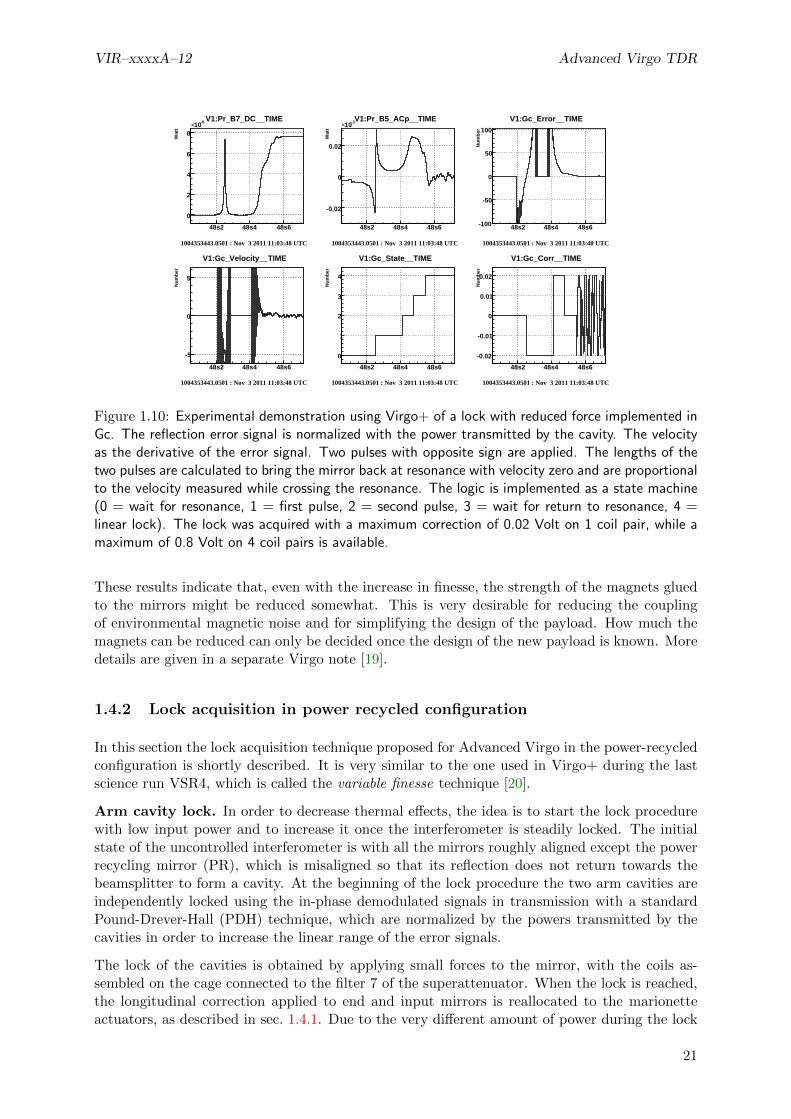
Such strategies have been tested experimentally just before the shutdown of Virgo+ with goodresults. It was even possible to lock the cavities with a force that was 160 times lower than themaximum available force, see Fig. 1.10. One important observation was that to keep the cavitylocked with low force for more than a few seconds, it is necessary to immediately reallocate thelow frequency part of the correction to the marionette actuators.
Similar tests were done in simulation using the optical parameters of Advanced Virgo, seeFig. 1.11. They show that the scheme should still work for the optical properties of the fu-ture cavities. Still missing from the simulation are an accurate representation of the mechanicsand the noise in the detection process. The exact noise level that can be tolerated has still tobe determined.
20
VIR–xxxxA–12 Advanced Virgo TDR
48s2 48s4 48s6
Wat
t
0
2
4
6
8
-610×
1004353443.0501 : Nov 3 2011 11:03:48 UTC
V1:Pr_B7_DC__TIME
1004353443.0501 : Nov 3 2011 11:03:48 UTC1004353443.0501 : Nov 3 2011 11:03:48 UTC
48s2 48s4 48s6
Wat
t
-0.02
0
0.02
-310×
1004353443.0501 : Nov 3 2011 11:03:48 UTC
V1:Pr_B5_ACp__TIME
1004353443.0501 : Nov 3 2011 11:03:48 UTC
48s2 48s4 48s6
Nu
mb
er
-100
-50
0
50
100
1004353443.0501 : Nov 3 2011 11:03:48 UTC
V1:Gc_Error__TIME
1004353443.0501 : Nov 3 2011 11:03:48 UTC
48s2 48s4 48s6
Nu
mb
er
-5
0
5
1004353443.0501 : Nov 3 2011 11:03:48 UTC
V1:Gc_Velocity__TIME
1004353443.0501 : Nov 3 2011 11:03:48 UTC
48s2 48s4 48s6
Nu
mb
er
0
1
2
3
4
1004353443.0501 : Nov 3 2011 11:03:48 UTC
V1:Gc_State__TIME
1004353443.0501 : Nov 3 2011 11:03:48 UTC
48s2 48s4 48s6
Nu
mb
er
-0.02
-0.01
0
0.01
0.02
1004353443.0501 : Nov 3 2011 11:03:48 UTC
V1:Gc_Corr__TIME
1004353443.0501 : Nov 3 2011 11:03:48 UTC
Figure 1.10: Experimental demonstration using Virgo+ of a lock with reduced force implemented inGc. The reflection error signal is normalized with the power transmitted by the cavity. The velocityas the derivative of the error signal. Two pulses with opposite sign are applied. The lengths of thetwo pulses are calculated to bring the mirror back at resonance with velocity zero and are proportionalto the velocity measured while crossing the resonance. The logic is implemented as a state machine(0 = wait for resonance, 1 = first pulse, 2 = second pulse, 3 = wait for return to resonance, 4 =linear lock). The lock was acquired with a maximum correction of 0.02 Volt on 1 coil pair, while amaximum of 0.8 Volt on 4 coil pairs is available.
These results indicate that, even with the increase in finesse, the strength of the magnets gluedto the mirrors might be reduced somewhat. This is very desirable for reducing the couplingof environmental magnetic noise and for simplifying the design of the payload. How much themagnets can be reduced can only be decided once the design of the new payload is known. Moredetails are given in a separate Virgo note [19].
1.4.2 Lock acquisition in power recycled configuration
In this section the lock acquisition technique proposed for Advanced Virgo in the power-recycledconfiguration is shortly described. It is very similar to the one used in Virgo+ during the lastscience run VSR4, which is called the variable finesse technique [20].
Arm cavity lock. In order to decrease thermal effects, the idea is to start the lock procedurewith low input power and to increase it once the interferometer is steadily locked. The initialstate of the uncontrolled interferometer is with all the mirrors roughly aligned except the powerrecycling mirror (PR), which is misaligned so that its reflection does not return towards thebeamsplitter to form a cavity. At the beginning of the lock procedure the two arm cavities areindependently locked using the in-phase demodulated signals in transmission with a standardPound-Drever-Hall (PDH) technique, which are normalized by the powers transmitted by thecavities in order to increase the linear range of the error signals.
The lock of the cavities is obtained by applying small forces to the mirror, with the coils as-sembled on the cage connected to the filter 7 of the superattenuator. When the lock is reached,the longitudinal correction applied to end and input mirrors is reallocated to the marionetteactuators, as described in sec. 1.4.1. Due to the very different amount of power during the lock
21

Advanced Virgo TDR VIR–xxxxA–12
0.050.000.050.100.150.200.25
mW
Cavity transmission
0.80.60.40.20.00.20.40.60.8
a.u.
Pound-Drever-Hall signal
1.00.50.00.51.0
a.u.
Correction
10505
1015
nm
Cavity length
5.23 5.24 5.25 5.26 5.27 5.28 5.29 5.30 5.31 5.32Time (s)
1.00.50.00.51.01.52.02.53.0
um/s
Velocity
Figure 1.11: Lock acquisition of an Advanced Virgo arm cavity, as simulated with e2e. Note thatthe cavity length and velocity are properties that are only available in simulation and cannot beobserved directly in reality. They are normally estimated, as described in the caption of Fig. 1.10 asthe derivative of the error signal on resonance crossing.
procedure, two different photodiodes could be needed to detect the transmitted light by the endmirrors: one for low power at the beginning of the procedure and the other for high power insteady state.
Half fringe lock. At the dark port, the resonance condition is initially chosen to be at halffringe (half of the maximum possible power is transmitted), which is outside the linear rangeof the demodulated signal. A method using the DC powers is therefore used to lock the MICHdegree of freedom: the ratio of the power transmitted to the dark port over the power impingingon the arm cavities (read with the PR pickoff beam) gives an estimation of the Michelson fringevalue. The fringe offset is set to 0.5 at the beginning, which is a standard side of fringe lockingof a Michelson interferometer and does not depend on any optical parameter of the cavities. Thelock acquisition of the MICH loop is thus virtually identical to the one used for initial Virgo.
Frequency stabilization. After these first steps, in Virgo and Virgo+ the control strategy ofthe two arms is modified. The SSFS, which keeps the laser frequency locked to the mean lengthof the arms below some tens of kHz (see 1.3.9 and [18]) is engaged. The control of DARM ismade by exploiting an error signal given by the transmission of one of the two cavities. TheCARM control is instead implemented using an error signal from the Reference Cavity (RFC)reflection with about 1 Hz of bandwidth: in this way the low frequency residual motion of theend mirror and of the laser frequency are reduced to a suitable value (see also sec. 1.3.4 forCARM accuracy requirements).
In the Advanced Virgo case the error signal foreseen for the SSFS comes from the interferometerreflection (see sec. 1.3.6) and it is not available before the PR is aligned. It might be necessarytherefore to modify the described strategy: the SSFS could be engaged after the realignment ofthe PR (this was done in Virgo at the time of the first commissioning runs) or it could use adifferent error signal for the lock acquisition (like B4 as done in Virgo and Virgo+) and switch
22

VIR–xxxxA–12 Advanced Virgo TDR
Misaligned PR Aligned PR Science Mode
MICH Offset [m] 1.33 · 10−7 1.33 · 10−7 1.60 · 10−9
B1p [W] 2.45 · 10−2 2.41 · 10−1 8.34 · 10−3
B2 [W] 1.22 · 10−3 7.48 · 10−1 1.61 · 10−1
B4 [W] 1.50 · 10−5 1.48 · 10−4 1.14 · 10−2
B7 [W] 6.91 · 10−6 6.82 · 10−5 5.28 · 10−3
Arm power [W] 6.91 6.82 · 101 5.28 · 103
Table 1.8: DC powers of various output ports during the lock acquisition, for 1 Watt of input power.Arm cavities are always locked. Note that in the real interferometer B1p power will depend stronglyon contrast defect and higher order mode contents.
to the final signal later.
PR realignment. At this point of the lock acquisition, the PR is realigned. During thistransition the circulating power inside the interferometer increases by a large amount. Thereforeall the signals are subjected to a large change in their optical gain, which is compensated by theuse of suitable normalization. At the same time the longitudinal control of the PR is engagedusing an error signal normalized by the value of the power inside the recycling cavity. Notethat the finesse of the recycling cavity is in this configuration dominated by the loss of the shortMichelson interferometer at half fringe. The lock acquisition of the PRCL loop should thusbe virtually identical to the one used in Virgo and Virgo+. This is the first condition of theinterferometer with all mirror aligned and all longitudinal degrees of freedom controlled.
MICH offset reduction.The locking point of the MICH loop is finally moved in several stepstowards its final value, which is close to the dark fringe, see sec. 1.3.3. During this transitionthe power in the cavities increases by about a factor 100 and gains of the lock loops have tobe changed accordingly. An analysis of the different condition in lock acquisition procedure hasbeen carried out using the simulation tool e2e [3]. In Tab. 1.8 the calculated values for the DCpower of various output ports during the lock acquisition for 1 W of input power are shown.The large excursion of the power impinging on the diodes might require the use of switchablesets of electronic gain.
Reaching dark fringe. The DARM loop control is then switched to a demodulated signalcoming from the beam extracted before the OMC (B1p). The automatic alignment for the alldegrees of freedom is engaged.
OMC and low noise configuration. The procedure that put the OMC in resonance is thenstarted and the DARM loop control is finally switched to the DC readout signal in transmissionof the OMC (B1). At this point the interferometer is locked in a robust configuration and theoperating point is very close to the final one. When the interferometer is in a steady condition,the input power is increased to the final value. When all the thermal effects connected to theincrease of the input power are stabilized, the control filters of all the longitudinal and angulardegrees of freedom are optimized in order to reduce control noise below the requirements. Allthe actions performed at the end of the lock acquisition procedure are focused to improve asmuch as possible the sensitivity of the detector (for example engaging of noise subtraction paths,etc.).
As explained in sec. 1.3.3, we do not expect large effects due to radiation pressure in the powerrecycled configuration, provided the idea of putting the DC readout offset on MICH is feasibleas shown in simulations.
23

Advanced Virgo TDR VIR–xxxxA–12
1.4.3 Lock acquisition in dual-recycled configuration
So far the lock acquisition of Advanced Virgo in the dual recycled configuration has not beenstudied yet. One possible solution would be to follow the strategy employed by LIGO, which isbriefly explained here. The idea is to first lock the arm cavities using an auxiliary laser, with atechnique similar to the one described in the next section 1.5. After this, the lock is transferred tothe main laser, using an error signal calculated from the DC signals in transmission of the cavities.A very large offset is applied to the CARM degree of freedom, so that the cavities are almostout of fringe. In this condition, the PRCL and SRCL degrees of freedom are locked. Finally,the offset is adiabatically removed. During this transition, the opto-mechanical resonance ofthe interferometer shifts in frequency, causing large changes in the optical transfer functions. Itappeared that the signals of the central interferometer demodulated at 3 times the modulationfrequencies are more robust during this transition, since they depend more on the resonancecondition of the sidebands, than on the carrier that resonates in the arm cavities [7].
An alternative method might be to extend the current variable finesse technique to the lock ofthe SRCL degree of freedom. The idea would be to first lock the two arm cavities with boththe PR and SR misaligned, lock MICH at half fringe and then align both mirrors one at a time.Finally, the offset of MICH would be adiabatically moved towards the dark fringe.
The lock acquisition strategy for the dual recycled interferometer is at this stage not a highpriority task, since it is expected that during the first commissioning phases the Advanced Virgodetector will run in power recycled configuration. Nevertheless the study of the lock acquisitionin dual recycled configuration will start in the next months and first results are expected at thebeginning of the next year.
1.5 Auxiliary lasers
1.5.1 Goals of the auxiliary lasers
The use of auxiliary lasers was first proposed to lock the very high finesse (1200 and then 900)long cavities in the Advanced Virgo design. The idea is to use an auxiliary laser at a wavelengthfar from 1064 nm so that the finesse seen by it can be chosen independently of the one seen bythe main laser. A low finesse (typically lower than 10) makes the lock of the cavity easy andallows to control its length down to a nm precision. It is then sufficient to change the workingpoint of the lock (or the frequency of the laser) to be able to cross a resonance of the main laserand then switch to the latter one for the full control.
With the current finesse for Advanced Virgo (443), it has been shown that even if we reduce theactuator maximum forces by a factor 5 (with respect to Virgo+ during the lock acquisition) wecan still lock the long arm cavities with the main laser [21] using a Virgo-like technique. There-fore, as explained in sec. 1.4.2, the lock acquisition strategy in the power recycled configurationwill be very similar to the Virgo one and there will be no need of auxiliary lasers.
However we will still face the problem to lock the interferometer with the presence of the signalrecycling mirror, which will increase the complexity to acquire the lock. As explained in theprevious section, the lock acquisition will be eased if we can have the long cavities frozen but offresonance from the main laser. Such action could be performed with an auxiliary laser as longas we can control the long cavities without getting the main laser resonating in the arms duringthe five minutes planned for the lock acquisition of the central interferometer.
Therefore the design and integration of the auxiliary laser system in Advanced Virgo can be breakdown in two steps. The interferometer must be designed in order to be compatible with the
24
VIR–xxxxA–12 Advanced Virgo TDR
600 700 800 900 1000 1100 1200 1300 14000
10
20
30
40
50
60
70
80
90
100
wavelength (nm)
Tra
nsm
issio
n (
%)
EM model
EM modelisation @ 1319 nm
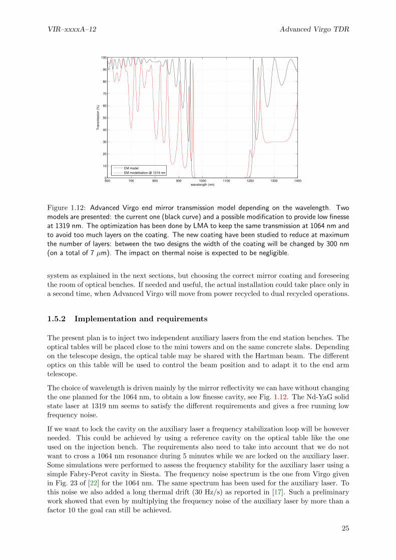
Figure 1.12: Advanced Virgo end mirror transmission model depending on the wavelength. Twomodels are presented: the current one (black curve) and a possible modification to provide low finesseat 1319 nm. The optimization has been done by LMA to keep the same transmission at 1064 nm andto avoid too much layers on the coating. The new coating have been studied to reduce at maximumthe number of layers: between the two designs the width of the coating will be changed by 300 nm(on a total of 7 µm). The impact on thermal noise is expected to be negligible.
system as explained in the next sections, but choosing the correct mirror coating and foreseeingthe room of optical benches. If needed and useful, the actual installation could take place only ina second time, when Advanced Virgo will move from power recycled to dual recycled operations.
1.5.2 Implementation and requirements
The present plan is to inject two independent auxiliary lasers from the end station benches. Theoptical tables will be placed close to the mini towers and on the same concrete slabs. Dependingon the telescope design, the optical table may be shared with the Hartman beam. The differentoptics on this table will be used to control the beam position and to adapt it to the end armtelescope.
The choice of wavelength is driven mainly by the mirror reflectivity we can have without changingthe one planned for the 1064 nm, to obtain a low finesse cavity, see Fig. 1.12. The Nd-YaG solidstate laser at 1319 nm seems to satisfy the different requirements and gives a free running lowfrequency noise.
If we want to lock the cavity on the auxiliary laser a frequency stabilization loop will be howeverneeded. This could be achieved by using a reference cavity on the optical table like the oneused on the injection bench. The requirements also need to take into account that we do notwant to cross a 1064 nm resonance during 5 minutes while we are locked on the auxiliary laser.Some simulations were performed to assess the frequency stability for the auxiliary laser using asimple Fabry-Perot cavity in Siesta. The frequency noise spectrum is the one from Virgo givenin Fig. 23 of [22] for the 1064 nm. The same spectrum has been used for the auxiliary laser. Tothis noise we also added a long thermal drift (30 Hz/s) as reported in [17]. Such a preliminarywork showed that even by multiplying the frequency noise of the auxiliary laser by more than afactor 10 the goal can still be achieved.
25

Advanced Virgo TDR VIR–xxxxA–12
We think we can use two lasers with the same wavelength for the two arms and select a differentpolarization for each of them. Then a polarizer will be needed for all photodiodes used in thesystem. The design of the optical table is currently under study. The system will be a standardone with laser and optics to select the polarization, a pickoff towards the reference cavity, anElectro-optical modulator (EOM), a telescope to match the beam to the end arm detection tableand some motorized optics for alignment. We will use a set of photodiodes to control the lasers(power and frequency) and the long cavity by using the reflected beam. We will also controlthe position and alignment of the beam with some quadrants photodiodes. The loops to controlthe laser will be done locally. The control of the cavity will be performed directly in the lockingalgorithm of the global control system.
When the lock acquisition procedure will be completed, we will switch off the auxiliary lasers toavoid any perturbation to the detector in Science Mode.
The auxiliary lasers will not be needed before the installation of the SR and so their installationcan be delayed up to that time. The different interactions with the MIR, DAQ and DETsubsystems have been defined and taken into account in their designs. The installation couldbe done in two steps. We could start to construct the in-air optical table independently andcharacterize the beam and the different optical elements. This phase may be done in LAL beforebringing the elements on site. Otherwise we could start the installation in the end arm station.Finally we will need to have access to the long cavities to align the beam correctly for at leastone month per arm.
Most of the requirements and techniques will be tested on the CALVA platform under commis-sioning in the Laboratoire de l’Accelerateur Lineaire.
1.6 Sideband aberration risk reduction strategy
Simulations of thermal effects and mirror surface and substrate defects in the power recyclingcavity showed a large sensitivity of radiofrequency sidebands. Very large aberrations can degradesignificantly the quality of the longitudinal error signals. The thermal compensation system isdesigned to be able to measure and compensate these effects. However it is important, at leastin the first stages of commissioning, to have a strategy to robustly control the interferometereven in presence of strong sideband aberrations.
Modal and FFT simulations show that the sideband sensitivity to PRC defects depends on theirrecycling gain. The larger it is the more sensitive the sidebands are to defects [8]. For thisreason an additional modulation frequency of 21 times the first one f4 = 131.686317 MHz willbe used. The corresponding sideband will have a recycling gain of few units and will be poorlysensitive to PRC defects.
Signals from this additional modulation frequency will be needed at all central part ports andthey will be used to control the interferometer in the first steps of commissioning of the thermalcompensation system. The modulation depth could be smaller than the one of the main mod-ulation and the photodiode requirements in term of demodulation noise and efficiency could berelaxed, since these signals will be used during the lock acquisition stage when noise performancesare not critical.
26

VIR–xxxxA–12 Advanced Virgo TDR
RR EMX
θ θEMXIMX
θ
REMX
θ IMX
θ EMX
R IMX
θ
Figure 1.13: Effect of radiation pressure in a Fabry-Perot cavity. The two mirror modes becomeconnected by an optical spring. The Fabry-Perot cavity misalignments can be described using the(+) plus and (-) minus modes. The combinations of single mirror misalignments giving the twomodes depend on the cavity geometry.
1.7 Angular control system
1.7.1 Introduction
In order to ensure long data taking periods the interferometer has to be kept on the chosenworking point, this means, among other things, that the core mirrors have to be aligned withrespect to the beam. So a global angular control system or automatic alignment (AA) systemhas to be implemented.
The main differences between the Advanced Virgo and the Virgo interferometer configurationsare the higher circulating power and the presence of the signal recycling cavity. These modifi-cations produce an improvement in the interferometer sensitivity but an increase of complexityfor the development of the AA control system:
High circulating power: the high amount of laser power produces strong radiation pressureeffects, as it will be detailed in sec. 1.7.2, which modify the mechanical transfer functionsof the angular degrees of freedom.
Presence of the signal recycling cavity: it adds to the number of degrees of freedom tocontrol and further increases the off-diagonal couplings in the AA error signals.
The AA control system has been fully designed in the three configurations already described inthe introduction: power recycled only at 25 W, dual recycled at 25 W and 125 W.
The design consisted in the definition of accuracy requirements (the maximum allowable mis-alignments which do not affect the interferometer performances) and the development of thesensing and control scheme, including the evaluation of control noises.
This analysis has been carried out using the simulation tools Finesse [1] and Optickle [2].
Finally requirements for other subsystems are given: quadrant photodiodes specifications (quan-tity, demodulation frequencies, etc ...) and suspension requirements for the terminal detectionbenches.
1.7.2 Radiation pressure effect and angular modes
In a high power interferometer radiation pressure plays an important role. The laser beam actson the mirror with force proportional to the power. The largest effect is present in the long arm
27
Advanced Virgo TDR VIR–xxxxA–12
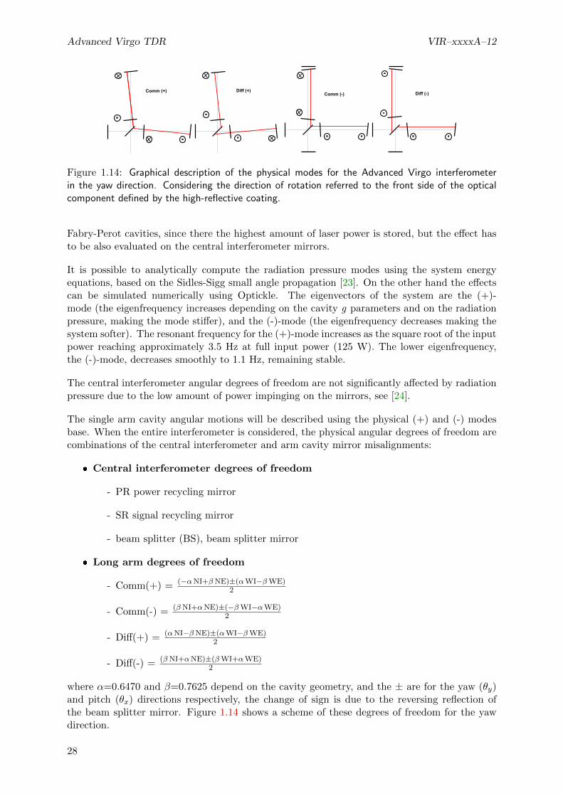
Comm (+) Diff (+)Comm (-) Diff (-)
Figure 1.14: Graphical description of the physical modes for the Advanced Virgo interferometerin the yaw direction. Considering the direction of rotation referred to the front side of the opticalcomponent defined by the high-reflective coating.
Fabry-Perot cavities, since there the highest amount of laser power is stored, but the effect hasto be also evaluated on the central interferometer mirrors.
It is possible to analytically compute the radiation pressure modes using the system energyequations, based on the Sidles-Sigg small angle propagation [23]. On the other hand the effectscan be simulated numerically using Optickle. The eigenvectors of the system are the (+)-mode (the eigenfrequency increases depending on the cavity g parameters and on the radiationpressure, making the mode stiffer), and the (-)-mode (the eigenfrequency decreases making thesystem softer). The resonant frequency for the (+)-mode increases as the square root of the inputpower reaching approximately 3.5 Hz at full input power (125 W). The lower eigenfrequency,the (-)-mode, decreases smoothly to 1.1 Hz, remaining stable.
The central interferometer angular degrees of freedom are not significantly affected by radiationpressure due to the low amount of power impinging on the mirrors, see [24].
The single arm cavity angular motions will be described using the physical (+) and (-) modesbase. When the entire interferometer is considered, the physical angular degrees of freedom arecombinations of the central interferometer and arm cavity mirror misalignments:
Central interferometer degrees of freedom
- PR power recycling mirror
- SR signal recycling mirror
- beam splitter (BS), beam splitter mirror
Long arm degrees of freedom
- Comm(+) = (−αNI+βNE)±(αWI−βWE)2
- Comm(-) = (βNI+αNE)±(−βWI−αWE)2
- Diff(+) = (αNI−βNE)±(αWI−βWE)2
- Diff(-) = (βNI+αNE)±(βWI+αWE)2
where α=0.6470 and β=0.7625 depend on the cavity geometry, and the ± are for the yaw (θy)and pitch (θx) directions respectively, the change of sign is due to the reversing reflection ofthe beam splitter mirror. Figure 1.14 shows a scheme of these degrees of freedom for the yawdirection.
28
VIR–xxxxA–12 Advanced Virgo TDR
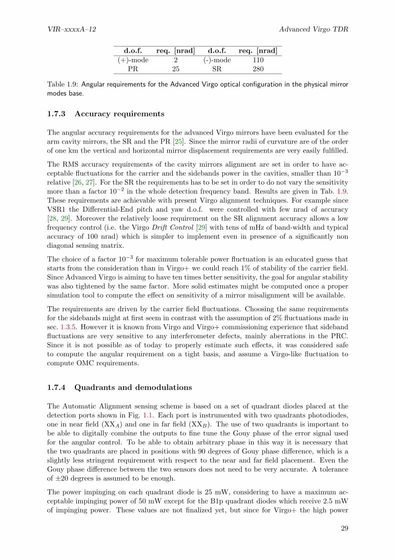
d.o.f. req. [nrad] d.o.f. req. [nrad]
(+)-mode 2 (-)-mode 110PR 25 SR 280
Table 1.9: Angular requirements for the Advanced Virgo optical configuration in the physical mirrormodes base.
1.7.3 Accuracy requirements
The angular accuracy requirements for the advanced Virgo mirrors have been evaluated for thearm cavity mirrors, the SR and the PR [25]. Since the mirror radii of curvature are of the orderof one km the vertical and horizontal mirror displacement requirements are very easily fulfilled.
The RMS accuracy requirements of the cavity mirrors alignment are set in order to have ac-ceptable fluctuations for the carrier and the sidebands power in the cavities, smaller than 10−3
relative [26, 27]. For the SR the requirements has to be set in order to do not vary the sensitivitymore than a factor 10−2 in the whole detection frequency band. Results are given in Tab. 1.9.These requirements are achievable with present Virgo alignment techniques. For example sinceVSR1 the Differential-End pitch and yaw d.o.f. were controlled with few nrad of accuracy[28, 29]. Moreover the relatively loose requirement on the SR alignment accuracy allows a lowfrequency control (i.e. the Virgo Drift Control [29] with tens of mHz of band-width and typicalaccuracy of 100 nrad) which is simpler to implement even in presence of a significantly nondiagonal sensing matrix.
The choice of a factor 10−3 for maximum tolerable power fluctuation is an educated guess thatstarts from the consideration than in Virgo+ we could reach 1% of stability of the carrier field.Since Advanced Virgo is aiming to have ten times better sensitivity, the goal for angular stabilitywas also tightened by the same factor. More solid estimates might be computed once a propersimulation tool to compute the effect on sensitivity of a mirror misalignment will be available.
The requirements are driven by the carrier field fluctuations. Choosing the same requirementsfor the sidebands might at first seem in contrast with the assumption of 2% fluctuations made insec. 1.3.5. However it is known from Virgo and Virgo+ commissioning experience that sidebandfluctuations are very sensitive to any interferometer defects, mainly aberrations in the PRC.Since it is not possible as of today to properly estimate such effects, it was considered safeto compute the angular requirement on a tight basis, and assume a Virgo-like fluctuation tocompute OMC requirements.
1.7.4 Quadrants and demodulations
The Automatic Alignment sensing scheme is based on a set of quadrant diodes placed at thedetection ports shown in Fig. 1.1. Each port is instrumented with two quadrants photodiodes,one in near field (XXA) and one in far field (XXB). The use of two quadrants is important tobe able to digitally combine the outputs to fine tune the Gouy phase of the error signal usedfor the angular control. To be able to obtain arbitrary phase in this way it is necessary thatthe two quadrants are placed in positions with 90 degrees of Gouy phase difference, which is aslightly less stringent requirement with respect to the near and far field placement. Even theGouy phase difference between the two sensors does not need to be very accurate. A toleranceof ±20 degrees is assumed to be enough.
The power impinging on each quadrant diode is 25 mW, considering to have a maximum ac-ceptable impinging power of 50 mW except for the B1p quadrant diodes which receive 2.5 mWof impinging power. These values are not finalized yet, but since for Virgo+ the high power
29

Advanced Virgo TDR VIR–xxxxA–12
Port Angular control Beam centering
B1p f1, f2, DC 2×f2B2 f1, f2, f3 DCB4 f1, f2 DCB7 DCB8 DC
Table 1.10: Quadrant diode demodulation frequency specifications. In bold signals used for thecontrol
quadrant diodes can accept 30 mW of impinging power, a maximum tolerance of 50 mW couldbe feasible. On the other hand the maximum allowed beam power for the B1p quadrants is2.5 mW to be more conservative, since it is not clear up to now which is the amount of powerat the dark port which can be extracted from the main beam for angular control. Clearly if theamount of power will be higher the signal to noise ratio will improve with a square root law.
All quadrants will be equipped with fast galvo centering system. The quadrants on the endbenches will also need translation stages that might be used during the pre-alignment steps.
The quadrants have to be suspended in vacuum to reduce the spoiling of the signals, bothdemodulated and DC, due to seismic and acoustic noise. In Virgo and Virgo+, error signals,especially the DC ones, were dominated, below the Hz region, by air currents. Starting from10 Hz, where there should be only shot noise, seismic motion was instead the limiting factor(see also sec. 1.7.7). It is important to mention that in Virgo and Virgo+ the error signal usedto control the Differential-End DOF, which is the most critical one in term of control noise, wasdominated by the electronic noise given by analog to digital converters (ADC) non-linearities[29, 30, 31, 32]. The very large dynamical range needed for automatic alignment signals (typicallyof the order of 106-107) must be properly tackled in the design of the electronic readout system.
For angular control, demodulated signals at all three main frequencies will be used. Needsfor each port are summarized in Tab. 1.10. Some signals will be used for angular control ofthe interferometer mirrors, some other to extract spot position to maintain the sensor wellcentered. Not all the signals coming from the detection ports are used in the present controlscheme. These are highlighted in bold in Tab. 1.10. Nevertheless in the commissioning phasethe possibility to have a larger choice of signals, thus a flexible system, is mandatory. In Virgothe final control system has been developed in the years obtaining at the end a scheme whichis completely different with respect to the one foreseen in simulations. This happened due toITF imperfections and improvements and also due to the lack of complete and perfectly reliablealignment simulations.
Even for Advanced Virgo there is not a proper simulation tool available which allows to studythe behavior of the alignment system as a function of possible unwanted effects (such as thermaleffects, robustness versus interferometer working points etc...). As mentioned before the toolspresently used are Finesse and Optickle. Optickle can take into account the radiation pressureeffect, fundamental in the high power interferometers, but considers only the first higher ordermode (not allowing the study of thermal effects, beam mismatches etc..) and no mirror staticmisalignments. On the other hand Finesse can take into account higher order modes but notradiation pressure effects. For all of these reasons, even if the control scheme which has beensimulated and designed works properly in simulation, it is important to have enough flexibilityand safety margins to be able to use a different control scheme with respect to the designed one,to deal with commissioning uncertainties and effects than could not be simulated nor foreseen.
30

VIR–xxxxA–12 Advanced Virgo TDR
1.7.5 Automatic Alignment control scheme
Sensing scheme
The Automatic Alignment control scheme has been modeled with Optickle, its control noise andthe control accuracy for each angular degree of freedom have been evaluated with Pickle [33],the Optickle tool to propagate the angular control noise to the sensitivity, together with theresidual mirror displacements, that was developed by the Advanced LIGO ISC group.
The only noise taken into account in the simulations is the shotnoise, thus if the sensing will bedominated by other sources of noise the angular control scheme has to be completely redesignedand the control noise reevaluated. In other words all quadrant photodiode signals are assumedto be shotnoise limited everywhere above 10 Hz.
In order to design the control scheme the sensing has been simulated by optimizing the amplitudeof the transfer functions between the angular degree of freedom and the quadrant diodes tuningthe Gouy and demodulation phases of the quadrants. The goal was to obtain the best decouplingof the angular degrees of freedom, taking care not to spoil the signal to noise ratio. In otherwords, whenever possible, the signal with larger SNR has been chosen.
It has been chosen to use a similar control scheme for all the three optical configurations (low,high power with and without SRC) in the sense that for each configuration a given angular d.o.f.is detected by the same detection port. Nevertheless, in each optical configuration parametersare retuned, such as demodulation and Gouy phases and control gains. Control filters are clearlydifferent in the high and low power regime to take into account radiation pressure effects on themechanical transfer function.
The optimal sensing scheme is the following:
- B1p demodulated at f2 used for Differential(+)
- difference of the DC signals coming from the terminal benches for Differential(−)
- B2 demodulated at f3 used for Common(+)
- sum of the DC signals coming from the terminal benches for Common(−)
- B4 demodulated at f1 for PR
- B1p DC signal for SR (controlled in Drift control mode)
- B4 demodulated at f2 for BS
Arm degrees of freedom control
The plane of the interferometer is kept fixed by the input beam control (not taken into account inthese simulations) and the (-)-modes, controlled with a DC signals using B7 and B8 quadrants.At low frequency (about 3 mHz) the (-)-modes error signal will be substituted with mirror tobeam relative centering signals to minimize the angular to longitudinal coupling. Such signalscan be obtained using a dithering technique as done for the Virgo input mirrors centering [29].Otherwise, as recently proposed, processed camera images [34] might provide the needed signals.
A clear difference between the Virgo and the Advanced Virgo angular control is the suppres-sion of the (+)-modes sensing due to the radiation pressure effects. Increasing the circulatingpower the (+)-modes become more and more stiff, reaching a mechanical resonance frequencyof about 3.5 Hz at full power. The decoupling of the sensing matrix is also reduced, makingthe interferometer more sensitive to possible optical imperfections. As an example, the high
31

Advanced Virgo TDR VIR–xxxxA–12
power interferometer configuration becomes the most critical configuration for mistuning of thelongitudinal working point, as it has been evaluated for the differential offset tuning [9].
Central cavity degrees of freedom control
The PR is controlled by using the first demodulation frequency while the BS using the second one.The BS and PR error signals can be exchanged if needed by retuning the Gouy and demodulationphases. It was chosen to use the best signal, in terms of SNR, for the PR since it is stronglycoupled with the Differential(+), especially in the final configuration [9]. This sensing schemeshould then assure the lowest PR control noise reintroduction in the Differential(+) mode.
The relaxed accuracy requirement for the SR (280 nrad) allows to adopt a hierarchical controlstrategy, using a low frequency control for the SR mirror with a bandwidth of some tens of mHz.This strongly simplifies the angular control decoupling. In Virgo the drift control developed forthe input mirrors, which used a dithering technique to generate the error signals, achieved acontrol accuracy of about 100 nrad, which would be already compliant with the Advanced Virgorequirements for SR.
Discussion
After the control scheme was designed the sensor noise has been projected in the dark fringe.The requirement is, as in the longitudinal case, that all noise contributions must remain a factor10 below the design sensitivity. In the angular control case this safety factor is even moreimportant since it must also take into account the uncertainty in the simulation results.
In all the three studied configurations the control scheme is compliant with the specifications ofcontrol accuracy and control noise and it does not show any evident difficulties for the baselinedesign (as the decoupling of the sensing, the design of the control filtering etc...) [9]. The mostcritical degrees of freedom in term of control noise, for all the three configurations, are the (-)-modes which are controlled with DC signals coming from the terminal benches. For this reasonit is mandatory to have these sensors shotnoise limited. The performance of the end benchessuspension becomes very important, see sec. 1.7.7.
In the power recycled only configuration at 25 W input power, the sensing is very well decoupledand the angular control noise is compliant with the factor 10 of safety below the sensitivitycurve. Radiation pressure effects do not affect strongly the cavity modes. This configurationis the closest to the Virgo+ one. The experience gained in the past years will help the firstcommissioning phases.
In the dual recycled at 25 W configuration, the angular control scheme is very similar to the firstone except for the introduction of the SRC. The Drift control applied to the SRC allows an easydecoupling of the signals which will help the implementation of an angular control compliantwith the sensitivity requirements.
The final, dual recycled at full power configuration, which allows to reach the highest possiblesensitivity, results to be compliant with the control noise sensitivity requirements. This config-uration is the most critical one in terms of angular degrees of freedom decoupling, due to the(+)-mode sensing suppression and the presence of the SRC. The system is controllable, but itsdecoupling may become worrying as soon as optical defects occur in the real interferometer [9].Indeed, in Virgo and Virgo+ we have experienced a strong coupling between the BS and PRmirror angular d.o.f. (a sensing ratio of 1:1) which made the commissioning and the imple-mentation of the complete automatic alignment system longer and more difficult than initiallyforeseen. For instance up to VSR4, spring 2011, we could not control both degrees of freedom
32

VIR–xxxxA–12 Advanced Virgo TDR
PR SR BS
B4 f1 103.4 0 -74.4B1p A DC 0 1 0B4 f2 -2.1 0 -4.3
Table 1.11: Sensing for the central interferometer degrees of freedom in case of high power configurationwith SR cavity, the most coupled configuration.
acting from the marionette. The PR had to be controlled by using the reference mass (which isnoisier with respect the control from the marionette) due to the fact that in the PR error signalthe BS resonances were visible and not mechanically damped. Table 1.11 shows the sensingmatrix for the central interferometer degrees of freedom in the dual recycled configuration.
Moreover when some optical defects were present in the interferometer (such as thermal tran-sients, higher order modes circulating in the cavities, not optimally tuned working point etc.) itwas not possible to find two independent and noiseless signals to control both the BS and thePR mirrors. In VSR3 only the BS was globally aligned since the mistuning of the end mirrorradii of curvature created lots of higher order modes which affected the angular error signal.The lack of a complete control system yielded a non reliable working point affecting the detectorduty cycle and sensitivity. These kind of issues will make the Advanced Virgo angular controlsystem commissioning more complex and longer.
1.7.6 Performances of the angular control system
The performances of the designed control system can be quantified with the mirror residualmotion in the AA closed loop configuration, and with the projection of angular control noiseto the Advanced Virgo sensitivity. The control filters have been designed in order to meet thesensitivity requirements starting from 10 Hz, while the low frequency part of the controls hasbeen tuned to meet, within a factor 2, the accuracy requirements. Further tunings are not usefulat this step of the design, since the mechanical transfer function of the new payloads is not fixedyet. See Fig. 1.15, 1.16 and 1.17: bottom plots for control noise and top plots for accuracyperformances.
The residual angular displacements and the AA control noise, evaluated with the Optickle sim-ulation, are in agreement with the accuracy and the sensitivity requirements, for all the threeconfigurations. The most critical degrees of freedom in terms of control noise are the (-)-modes,for all the three commissioning configurations.
In the final configuration, the high power dual recycled interferometer, the radiation pressuresuppresses the (+)-mode sensing. The consequence is a worse mode reconstruction, especiallyfor the Differential(+), which yield an excess of control noise. This fact is visible in Fig. 1.17where the control noise due to the Differential(+) mode, dashed blue line, is larger with respectto the B1p diode shotnoise contribution, blue line.
This behavior is not critical in simulation since the Differential(+) noise is far from the sensitivity,but the coupling can be stronger in a real interferometer leading to further increase of controlnoise.
1.7.7 Quadrant suspension requirements
The requirements for the quadrant suspension, tilt and translation, have been evaluated ana-lytically for the DC signals in transmission to the long arm cavities used for the control of the
33

Advanced Virgo TDR VIR–xxxxA–12
10−2
10−1
100
10−12
10−11
10−10
10−9
10−8
10−7
10−6
frequency (Hz)
rad/
sqrt
Hz
Residual pitch motion
NI TotNE TotWI TotWE TotPR TotBS TotNI RMSNE RMSWI RMSWE RMSPR RMSBS RMS
100
101
102
10−22
10−21
10−20
10−19
10−18
10−17
frequency (Hz)
m/s
qrtH
z
Angular Noise Coupling to DARM
B1pAP2
B7A
DC
B2A
P3
B8A
DC
B4A
P1
B1pAP1
SeismicDiff
PDiff
MComm
PComm
M
PRBSTotalDesign sensitivitySafety Factor
Figure 1.15: Mirror residual displacement and Automatic Alignment control noise projection for thefirst commissioning phase (low power interferometer without SRC) on the top and on the bottom plotrespectively. The mirror residual motions are close to the accuracy requirements and improvementmargins have been left in the filter design.
34

VIR–xxxxA–12 Advanced Virgo TDR
10−2
10−1
100
10−12
10−11
10−10
10−9
10−8
10−7
10−6
frequency (Hz)
rad/
sqrt
Hz
Residual pitch motion
NI TotNE TotWI TotWE TotPR TotSR TotBS TotNI RMSNE RMSWI RMSWE RMSPR RMSSR RMSBS RMS
100
101
102
10−22
10−21
10−20
10−19
10−18
10−17
frequency (Hz)
m/s
qrtH
z
Angular Noise Coupling to DARM
B1pAP2
B7A
DC
B2A
P3
B8A
DC
B4A
P1
B1pADC
B4AP2
SeismicDiff
PDiff
MComm
PComm
M
PRMSRMBSTotalDesign sensitivitySafety Factor
Figure 1.16: Mirror residual displacement and Automatic Alignment control noise projection for thelow power interferometer with SRC on the top and on the bottom plot respectively.
35
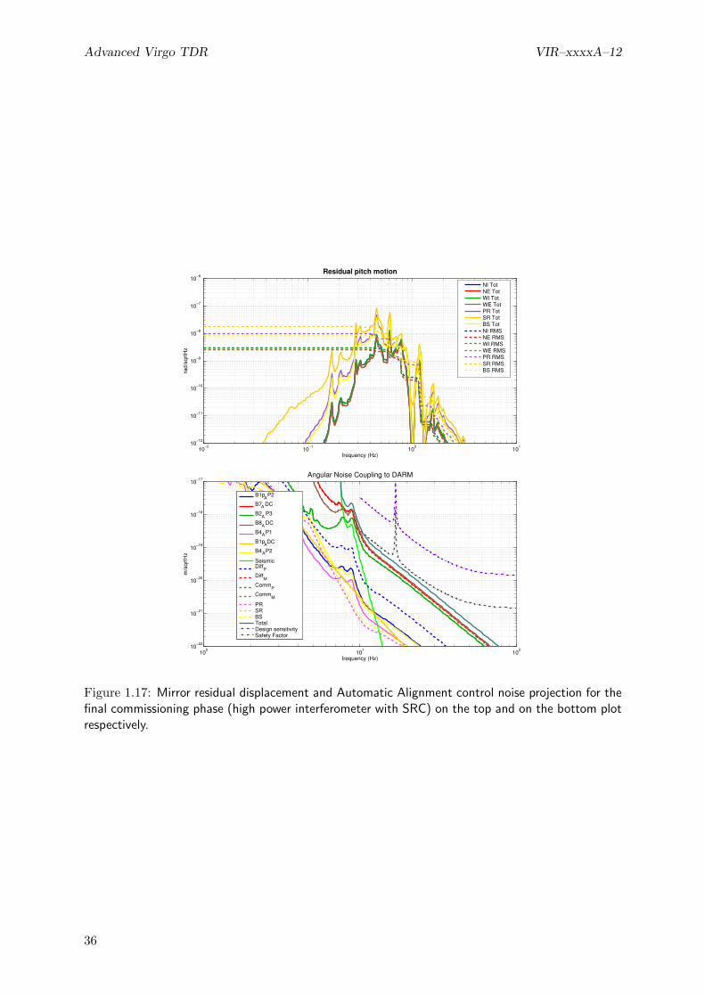
Advanced Virgo TDR VIR–xxxxA–12
10−2
10−1
100
101
10−12
10−11
10−10
10−9
10−8
10−7
10−6
frequency (Hz)
rad/
sqrt
Hz
Residual pitch motion
NI TotNE TotWI TotWE TotPR TotSR TotBS TotNI RMSNE RMSWI RMSWE RMSPR RMSSR RMSBS RMS
100
101
102
10−22
10−21
10−20
10−19
10−18
10−17
frequency (Hz)
m/s
qrtH
z
Angular Noise Coupling to DARM
B1pA
P2
B7A DC
B2A
P3
B8A DC
B4AP1
B1p ADC
B4AP2
SeismicDiff
PDiff
MComm
PComm
M
PRSRBSTotalDesign sensitivitySafety Factor
Figure 1.17: Mirror residual displacement and Automatic Alignment control noise projection for thefinal commissioning phase (high power interferometer with SRC) on the top and on the bottom plotrespectively.
36
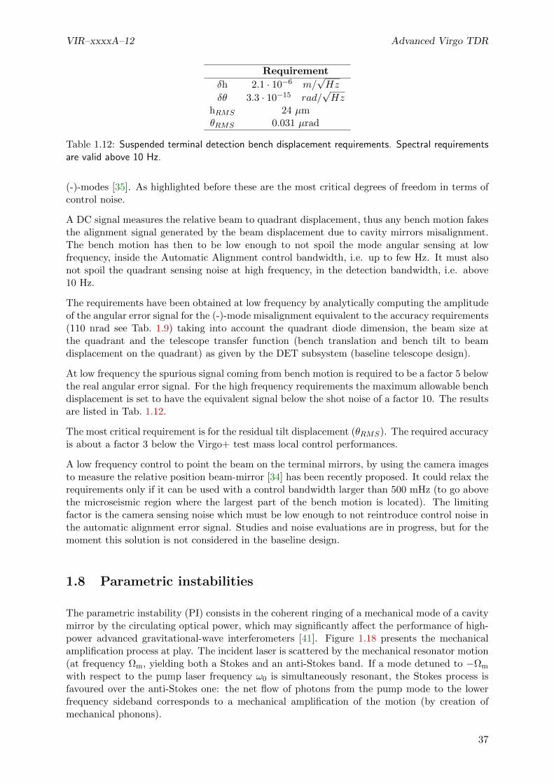
VIR–xxxxA–12 Advanced Virgo TDR
Requirement
δh 2.1 · 10−6 m/√Hz
δθ 3.3 · 10−15 rad/√Hz
hRMS 24 µmθRMS 0.031 µrad
Table 1.12: Suspended terminal detection bench displacement requirements. Spectral requirementsare valid above 10 Hz.
(-)-modes [35]. As highlighted before these are the most critical degrees of freedom in terms ofcontrol noise.
A DC signal measures the relative beam to quadrant displacement, thus any bench motion fakesthe alignment signal generated by the beam displacement due to cavity mirrors misalignment.The bench motion has then to be low enough to not spoil the mode angular sensing at lowfrequency, inside the Automatic Alignment control bandwidth, i.e. up to few Hz. It must alsonot spoil the quadrant sensing noise at high frequency, in the detection bandwidth, i.e. above10 Hz.
The requirements have been obtained at low frequency by analytically computing the amplitudeof the angular error signal for the (-)-mode misalignment equivalent to the accuracy requirements(110 nrad see Tab. 1.9) taking into account the quadrant diode dimension, the beam size atthe quadrant and the telescope transfer function (bench translation and bench tilt to beamdisplacement on the quadrant) as given by the DET subsystem (baseline telescope design).
At low frequency the spurious signal coming from bench motion is required to be a factor 5 belowthe real angular error signal. For the high frequency requirements the maximum allowable benchdisplacement is set to have the equivalent signal below the shot noise of a factor 10. The resultsare listed in Tab. 1.12.
The most critical requirement is for the residual tilt displacement (θRMS). The required accuracyis about a factor 3 below the Virgo+ test mass local control performances.
A low frequency control to point the beam on the terminal mirrors, by using the camera imagesto measure the relative position beam-mirror [34] has been recently proposed. It could relax therequirements only if it can be used with a control bandwidth larger than 500 mHz (to go abovethe microseismic region where the largest part of the bench motion is located). The limitingfactor is the camera sensing noise which must be low enough to not reintroduce control noise inthe automatic alignment error signal. Studies and noise evaluations are in progress, but for themoment this solution is not considered in the baseline design.
1.8 Parametric instabilities
The parametric instability (PI) consists in the coherent ringing of a mechanical mode of a cavitymirror by the circulating optical power, which may significantly affect the performance of high-power advanced gravitational-wave interferometers [41]. Figure 1.18 presents the mechanicalamplification process at play. The incident laser is scattered by the mechanical resonator motion(at frequency Ωm, yielding both a Stokes and an anti-Stokes band. If a mode detuned to −Ωm
with respect to the pump laser frequency ω0 is simultaneously resonant, the Stokes process isfavoured over the anti-Stokes one: the net flow of photons from the pump mode to the lowerfrequency sideband corresponds to a mechanical amplification of the motion (by creation ofmechanical phonons).
37

Advanced Virgo TDR VIR–xxxxA–12
w
pumplaser
Stokesband
anti-Stokesband
w W0 m- w
0 w W0 m+
Wm
w0
w W0 m-Acoustic
mode
TEM00
TEMpq
Figure 1.18: Interpretation of the three mode amplification process in terms of photon scattering bymechanical phonons to a different optical mode. Both the pump photon and the scattered one canbe simultaneously resonant into the cavity.
For a single cavity, the corresponding parametric gain for the mirror motion R is (for the Stokesprocess):
R =8F
λcMΓΩmPin Λ
(Ω2c
Ω2c + (ω0 − Ωm − ωho)2
), (1.12)
where M is the effecive mass of the vibration mode, Γ its damping, ωho the resonance frequencyof the higher-order optical mode, F and Ωc the associated finesse and optical bandwidth, andΛ the spatial overlap between optical modes and the mechanical one. Mirror motion (such asthermal noise) is amplified by this process up to an instability threshold (R = 1) where themirror is coherently set into motion by laser light.
Such a 3-mode parametric coupling has already been observed on large test masses in the Aus-tralian high-power laser facility [42] and in the LKB group [43], using an almost degenerateoptical cavity and a silicon micromirror, eventhough no experiment to date has been able toreach the parametric instability threshold. The advanced large scale interferometers, with theirvery high mechanical mode density at frequencies such as tens of kHz, unfortunately are verygood candidates to display such an instability.
After the seminal work of Braginsky on a single cavity [41], a number of groups have startedmodelling a complex interferometer, with dual recycling. The group led by D. Blair has shownthat for a given mechanical mode, the overall amplification effect may involve tens of higher-order optical modes [44]. The parametric gain should then take into account all optical modes,whether they have an amplification or a damping effect, and can be written for instance, for asingle cavity:
R =8Pin
λcMΓΩm
∑p,q
(Fpq Λpq Ω2
cpq
Ω2cpq + (ω0 − ωpq + Ωm)2
−Fpq ΛpqΩ
2cpq
Ω2cpq + (ω0 − ωpq − Ωm)2
), (1.13)
where the summation is on transverse optical modes p, q. To avoid instability, the gain Rmust remain below unity.
Detailed simulations of the impact of the PI by the Perth and MIT groups have shown that inthe current Advanced LIGO optical configuration, the number of unstable mechanical modesis unlikely to be below 5 for any set of optical parameters [44, 45]. Such modes are likelyto reach a very important vibration amplitude and therefore prevent any stable operation ofthe interferometer, eventhough most mechanical modes are outside the detection window. It istherefore of utmost importance to understand, fully compute and mitigate this instability.
The MatLab code first developed by UWA [44] has been adapted to Advanced Virgo and carefullychecked. The results so far only include a truncated (but yet significant) set of optical modes.The work already performed includes:
38

VIR–xxxxA–12 Advanced Virgo TDR
Ansys computations of the mechanical modes of the test masses (taking into account theirexact geometry)
computation of the mechanical quality factors, taking into account the losses due to theoptical coating
computation of the higher-order modes of the cavities of the interferometer, including theiroptical losses
computation of the spatial overlap between all possible triplets of modes (TEM00 pumpmode, mechanical mode, higher-order optical mode)
parametric gain R for each mechanical mode by summation of the extension of eq. (1.13)to a dual-recycled interferometer.
The computation can be performed for a number of optical configurations: single cavity, in-terferometer, interferometer with power or dual recycling, etc. Figure 1.19 presents one plotproduced by the code: parametric gain R for each mechanical mode up to 46 kHz, for a dual-recyled interferometer with Advanced Virgo specifications and an input power of 125 W. In sucha configuration, 13 modes (per test mass) are likely to be unstable, but this is an upper limit,computed under the assumption that the mechanical Qs are effectively limited by coating lossesand not clamping losses. The gain is proportional to the input power, so that for a lower one,the number of unstable modes is drastically decreased. In the case of 25 W, about 4 modes permirror remain unstable. As the results are strongly dependent on the (optical and mechanical)characteristics of the mirrors and the cavities, a statistical analysis has to be performed in orderto take into account the expected deviations of the actual mirrors from their specifications.
Possible mitigations strategies include:
passive damping (with resonant dampers) in order to decrease the Q and increase the PIthreshold
thermal tuning of the RoCs to a ’sweet spot’ with a lower number of unstable mechanicalmodes [46]
feedbak damping [47] by a combination of high-speed PI monitoring (at frequencies up to50 kHz) and efficient actuation on the mirror mode profiles (eg not a global actuation ofthe mirror center-of-mass)
The tasks to be completed include:
Computation of the PI gain with a larger set of optical modes, for a more accurate esti-mation of R
’Worst case’ statistical analysis, to take into account the highly sensitive character of theresults to small discrepancies
evaluation of the impact of the PI over the lock acquisition process
definition of a mitigation strategy
1.9 Software requirements
1.9.1 Fast realtime control
The realtime system that is currently used for both the lock acquisition and the steady statecontrol consists of a chain of several components (ADC,Photo-diode read-out (Pr), Gc, Digital
39

Advanced Virgo TDR VIR–xxxxA–12
Para
metr
ic|
|R
gain
Frequencies of mechanical modes (kHz)5 10 15 20 25 30 35 40 45 50
1
10-1
10-2
10-3
10-4
10
Figure 1.19: Example of a plot obtained with the PI simulation code: parametric gain |R| computedfor all mechanical modes of the suspended mirrors, up to 46 kHz, for a dual-recycled interferometer.Red dots indicate amplified modes (R > 0), blue dots damped ones. 13 modes (per test mass) arelikely to be unstable.
Signal Processor (DSP) and finally the Digital to analog converter (DAC)) that run at a samplefrequency of 10 kHz. It is expected that the realtime software that will be used for the longitu-dinal control of Advanced Virgo will not be fundamentally different from the current one. Someminor work might be required to remove some legacy parts or update to the future software en-vironment. The locking algorithm (which is part of Gc will probably be rewritten from scratch,which will be done in parallel with the commissioning activity.
The overall delay of all the components in the chain poses a limit on the unity gain frequencyof the locking loops. As discussed in 1.3.6, there might be a need to increase the unity gainfrequency to 400 Hz in case of a double-recycled interferometer, which is hard to achieve withthe current system. A reduction of the delays will be necessary, for example by increasing thesample frequency or optimizing the antialiasing filters. This is discussed in more detail in [xxref DAQ chapter].
The software chain used for controlling the angular degrees of freedom is pretty similar to theone used for the longitudinal part. The main difference is that it uses quadrant detectors insteadof photodiodes and that the control process runs at a much lower frequency (2 kHz typically).Since this is about an order of magnitude slower than the control system used for the longitudinalcontrols, it poses no extra requirements on the digital or analog delays of the control system.
1.9.2 Slow control
Most of the slow control of Virgo is performed using Automation of the Locking Procedure (ALP)servers. The whole lock acquisition currently takes between 10 and 20 minutes. This process isdriven by the AlpMain server, which basically executes a long lists of Cm commands that aresent to other processes, with the occasional waits and checks to see if a certain state is achieved.The whole sequence of the lock acquisition itself will have to be written from scratch, based onthe experience of the commissioning.
In addition to this simple sequencing, a number of servos is active that implement slow feedbackloops for stabilizing e.g. a unity gain frequency of a certain loop. Also these are implemented
40
VIR–xxxxA–12 Advanced Virgo TDR
in ALP (e.g. AlpLock, AlpTCS, etc.).
Since all the time critical actions are performed using realtime systems and since ALP is mainlyused to slowly change the configuration of the interferometer, the requirements on it are not veryhigh. It should therefore be no problem to use ALP as it is now to implement the slow controlof Advanced Virgo. ALP has, however, some limitations when it is used to implement complexlogic (e.g. subfunctions, exceptions, inter-process communication) and advanced calculations(e.g. vector math as in Matlab). These kind of operations were already important in Virgo+ andare more critical in Advanced Virgo, given the increased complexity of the system. We thereforepropose to investigate the possibility of using an existing scripting language in addition to or inplace of ALP, instead of upgrading ALP to obtain such new features. The migration to the newarchitecture will be needed only at the time of restart of the commissioning activities, thereforethis is not a priority task.
1.10 Interfaces with other subsystems
The design of both longitudinal and angular control systems creates several interfaces with othersubsystems. All the requirements are discussed in more details in the corresponding sections.
1.10.1 OSD
In order to control the power and signal recycling cavity longitudinal degrees of freedom a pickoffof the beam inside the recycling cavity is needed. This requires the addition of a plate in frontof the power recycling mirror to extract such a beam.
1.10.2 MIR
The use of Etalon effect in the input mirrors to tune the interferometer finesse asymmetry isan important risk reduction strategy (sec. 1.3.10 and 1.3.9). This implies the need of havinginput mirrors with parallel faces. To meet the sensitivity requirements, in the power recycledcase losses asymmetries must remain below 20 ppm and finesse asymmetry below 1% to be ableto meet the requirements.
The reflectivity of the power recycling pickoff plate is required to be about 300 ppm, in order tohave enough power in the pickoff beam even with low input power (sec. 1.3.2).
Auxiliary lasers at a wavelength different from the main one (sec. 1.5) needs a careful evaluationof the mirror coating performances at the new wavelength. We ask to have an arm cavity finessebetween 5 and 10 at 1319 nm for the coating of the mirror without changing the value of the1064 nm parameters. This requirements have already been obtained for the mirror installed inthe CALVA platform [4].
The angular control system foresees the use, even in science mode configuration, of signalscoming from quadrants in transmission of the end mirrors. In order to have a suitable amountof power in the beam a lower limit for the end mirror transmission must be set. In the caseof low input power (25 W), a transmission of 1 ppm gives about 150 mW of power on the endbenches, which seems a reasonable amount to be shared between diodes, quadrants and cameras.Therefore the end mirror transmission should be T ≥ 1 ppm.
41

Advanced Virgo TDR VIR–xxxxA–12
Frequency Phase noise [rad/√
Hz] Rel. ampl. noise [1/√
Hz]
6.3 MHz 1.8 · 10−6 1.7 · 10−7
56.4 MHz 1.1 · 10−6 1.1 · 10−6
8.4 MHz 0.27 1.7 · 10−7
Table 1.13: Summary of requirements for sideband amplitude and phase noise. Modulation noisesenters in the photodiode output signal following two paths. The first one is through the noise at thelevel of the modulation, which is transmitted to the laser beam and enters on one of the inputs ofthe mixer. The second path is through noise introduced by the local oscillator distribution system,which enters on the other input of the mixer. The requirements given here apply to the total of thetwo contributions.
Requirement
δh 2.1 · 10−6 m/√Hz
δθ 3.3 · 10−15 rad/√Hz
hRMS 24 µmθRMS 0.031 µrad
Table 1.14: Suspended terminal detection bench displacement requirements. Spectral requirementsare valid above 10 Hz.
1.10.3 INJ
The lock acquisition procedure might be strongly affected by radiation pressure issue. Moreoverinitial commissioning activities will be for sure carried out in a reduced input power regime.Both these considerations indicate the need of a system to continuously and smoothly tune theinput power from its minimum values up to the maximum.
Requirements on modulation phase and amplitude noise have been computed, based on thesteady state longitudinal control design. They are summarized in Tab. 1.13 (see sec. 1.3.7 formore details).
1.10.4 SBE
The end mirror transmitted beams will be sensed by two quadrant photodiodes for each port.Spot position (DC) signals will be used to control two angular degrees of freedom. Their requiredaccuracy gives limits on the spurious signal created by bench motion, which should give acontribution not larger than what would be equivalent to a beam translation inside the armcavity of the order of 20 µm. Provided the magnification properties of the telescope (designedto reduce the beam size to a reasonable value which will fit the sensor) the spot motion on thequadrant can be converted to angular and translational residual motion of the end benches. Therequirements obtained in this way are quite stringent and reported in Tab. 1.14 (see sec. 1.7.7for more details).
There are additional requirement on the bench motions inside the detector bandwidth, above10 Hz. In order to have error signals dominated by shot noise, the maximum bench motioncan be computed. With the present telescope design the required maximum bench motions aresummarized in Tab. 1.14 (see sec. 1.7.7 for more details).
42

VIR–xxxxA–12 Advanced Virgo TDR
Port photodiodes Quadrant photodiodes
Symmetric port (B2) DC, f1, 3f1, f2, f3 DC, f1, f2, f3Dark port after OMC (B1) DC
Dark port before OMC (B1p) DC, f1, f2, 2f1, 2f2 DC, f1, f2, 2f2OMC reflection (B1s) DC, f1, f2, 2f1, 2f2
Power Recycling pick off (B4) DC, f1, f2, 2f1, 2f2 DC, f1, f2Arm cavity transmission (B7, B8) DC , f1 DC
Table 1.15: Needed signals and demodulation frequencies at each interferometer output port.
Frequency [MHz] PR 25 W SR 25 W SR 125 W
6 1/120 1/7 1/3656 1/1700 1/460 1/2300
Table 1.16: Filtering requirements (in power) for the OMC in different interferometer configurations.
1.10.5 DET
The different demodulation frequencies needed at each port are summarized in Tab. 1.15. Inall ports the two quadrants should be placed in such a way to have the Gouy phase differencebetween them as close as possible to 90 degrees. In this way the signals from both quadrantscould be mixed digitally to reconstruct with high accuracy the needed Gouy phase. This isnecessary to proper decouple the angular degrees of freedom (sec. 1.7.4). All quadrants will usegalvo fast centering systems.
The requirement on the DARM longitudinal control loop (sec. 1.3.4), which comes from ISCconsiderations, have an impact on design requirements of the OMC. Any fluctuation of spuriousfields (sidebands or higher order modes) transmitted by the OMC is directly translated to amotion of the DARM degree of freedom, thus spoiling the loop accuracy (sec. 1.3.5). Fromthese considerations a requirement on the maximum sideband power which can be tolerated intransmission of the OMC is obtained to be of the order of 0.07 mW. This poses stringent limitson the OMC filtering capabilities. Tab. 1.16 summarizes the filtering requirement in differentconfigurations, using the estimate of sideband powers at the input of the OMC given in [36].
As anticipated in the INJ interface description, requirements on modulation phase and ampli-tude noise have been computed, based on the steady state longitudinal control design. Theserequirements are given in term of the total phase and amplitude noises at all mixer inputs, andtherefore apply also to the local oscillator distribution network. A summary can be found insec. 1.3.7 and Tab. 1.13.
Most of the photodiode and quadrant signals will have very large dynamical range (typically106-107 in Virgo+ angular signals). The full readout chain must be able to handle such largedynamics, without introducing up-conversion noise.
Auxiliary lasers (sec. 1.5) will go through the detection benches. Proper space to allow theneeded optical path must be prepared. Since a different wavelength will be used we will need aspecial dichroic element to separate the beams and also avoid any perturbation on the signalsobserved with the 1064 nm laser. For the latter point some beam dumpers may also be needed.
Time domain simulations done at LIGO suggest that in case of an unlock of a double-recycledinterferometer, a large part of the optical power stored in the interferometer (around 50 Joule)will exit the asymmetrical port in a very short time (less than 20 ms). Since the damage-threshold of a typical photodiode is on the order of 100 mJ, a very fast shutter is needed. To notcause any damage, the shutter must be almost completely closed within 1-2 ms after receiving
43

Advanced Virgo TDR VIR–xxxxA–12
Configuration 10 Hz 100 Hz 1000 Hz
PR 25 W 2 · 10−8 Hz−1/2 1.5 · 10−8 Hz−1/2 2 · 10−8 Hz−1/2
SR 125 W 4 · 10−9 Hz−1/2 9 · 10−9 Hz−1/2 9 · 10−9 Hz−1/2
Table 1.17: Summary of RIN requirements at the interferometer input. For the full dependence onthe frequency refer to Fig. 1.4 and 1.7.
a trigger, which might be based on the DC-power crossing a certain threshold [7]. This seemspretty demanding for a standard mechanical shutter.
DET sub-system fixed the DC-readout offset value in order to have a carrier power at dark portof 80 mW. From the point of view of ISC, it would be better to reduce as much as possiblethe offset. As explained in [9] the larger the offset the more coupled the angular sensing matrixbecomes.
1.10.6 PSL
The lock acquisition of the long arms requires the residual frequency noise with pre-stabilizedlaser to be significantly smaller than the cavity line-width, namely smaller than about 1 HzRMS.
Considering the coupling of frequency and power noise at the interferometer input to the detectorsensitivity in presence of some reasonable asymmetries, it is possible to draw requirementsfor the stabilization loops. This is in particular important for the power stabilization at theIMC transmission. The required relative intensity noise (RIN) depends on the interferometerconfiguration (sec. 1.3.8). A summary of the requirements are given in Tab. 1.17. More detailsare given in Fig. 1.4 and 1.7.
1.10.7 DAQ
All the control loop designs have been carried out without considering the effect of delays intro-duced by the real-time control system. Such delays might play an important role only in the caseof the DARM loop for dual recycled configuration, which has a unity gain frequency of about400 Hz [6]. This would impose a requirement on the total delay of about 50 µs which accordingto the DAQ subsystem would be difficult to reach. Therefore it is necessary to re-consider thedesign of the control. It seems feasible, although not yet designed, to reduce the band-width to200 Hz. This would relax the delay requirement to about 100 µs.
The automation of the entire lock procedure and the steady state operations requires an infras-tructure to implement scripting and slow servo loop, as was done in Virgo using ALP. A greaterflexibility with respect to the scripting and computational capabilities of ALP would be veryuseful (sec. 1.9) to improve the lock acquisition robustness and speed up the commissioning.
1.10.8 SAT
The issue of total delay in the DARM loop involves also the SAT subsystem, since part of thedelay must be accounted to the DSP, coil drivers and DAC controlling the mirror actuators.
The performances of the inertial damping system are important for the total residual RMSmotion of the mirrors. Indeed the RMS is almost completely accumulated at frequencies below1-2 Hz. The requirements for the longitudinal control accuracy are met by the control loops,
44
VIR–xxxxA–12 Advanced Virgo TDR
assuming the payload motion is the same as measured in Virgo (about 0.5 µm and 0.1 µradRMS). This implies that the mirror motion in Advanced Virgo must not be larger than theVirgo one. Moreover, any reduction of the mirror low frequency motion at the level of thesuspension system will help implementing more stable and less noisy longitudinal control loops.
1.10.9 PAY
The force needed to acquire and maintain the interferometer lock can be estimated starting fromsimple modeling and experimental verifications. The use of non-linear lock acquisition, whichwas experimentally proved in Virgo+, reduces the maximum force needed in high power of abouta factor 160 with respect to the Virgo+ actuators (sec. 1.4.1). A rough estimation indicates thatthe maximum force used in Virgo+ was of the order of 3 mN per coil-pair. Keeping some safetymargin, we can expect to reduce this by a factor 5-10. The exact value is still to be decided anddepends on the mechanics of the new payload and on the amount of sensor noise during the lockacquisition.
Early re-allocation to the marionette also virtually eliminates any requirement on the maximumactuation force on the mirror, from the need to maintain the lock.
The need of increasing the DARM loop band-width poses stringent requirements on the minimumpossible frequency of internal resonances of the structure holding the actuation coils. The presentdesign of the DARM control foresee and band-width of 400 Hz. Having all resonance above thisfrequency seems very difficult, therefore it is necessary to re-consider the design of the control.It seems feasible, although not yet designed, to reduce the band-width to 200 Hz.
The issue of parametric instabilities and the possible strategies to damp them, passively oractively, must be deeply investigated with the collaboration of the PAY sub-system.
1.10.10 INF
In the terminal stations, the space for auxiliary laser benches must be allocated near the mini-tower and on the same concrete slab. We need to check with the infrastructure group the safetyissues, as we will be placed on the roof of the clean room. We may also need an acoustic enclosureand we may be able to reuse the one installed around the end arm optical tables.
1.11 Summary and conclusions
The conceptual design of the steady state control of Advanced Virgo, both for angular andlongitudinal degrees of freedom, is concluded. Three different configurations have been studied:power recycled only at low input power, dual recycled at both low and full input power.
To be compliant with the detector scientific goal all control noises must remain a factor 10 belowthe design sensitivity in all studied configurations. To reach such performances the sensing noiseof all the error signals cannot exceed the shot noise level, given the maximum power that canbe sensed, as set by the DET subsystem.
The accuracy requirements for the control system have been computed based on considerationson the maximum tolerable power fluctuations and on noise up-conversion. The control sys-tems are compliant with such accuracy constraint, provided that some requirements to othersubsystems are fulfilled. In particular the longitudinal control poses constraints on the OMC per-formances and the angular ones on the end benches seismic attenuation system. Requirements
45

Advanced Virgo TDR VIR–xxxxA–12
on the laser technical noises at the interferometer input and on the interferometer asymmetriesare also derived. The need of a precise matching of the two input mirror reflectivities dictatesthe need of the Etalon effect and its control.
The performances of the ISC control system have been evaluated using modal simulation tools,namely Finesse and Optickle. The uncertainty in the modeling and in the simulation results isstill large. Indeed the large circulating power leads to strong radiation pressure effects. Sucheffects can be modeled only using Optickle, which on the other hand cannot use higher ordermodes and therefore does not give completely accurate results in particular for the angular con-trols. A tool capable of simultaneously handle higher order modes and radiation pressure wouldbe very important. Plans for the development of such a tool are being considered, compatiblywith the available manpower.
The study of the lock acquisition procedure has started only since few months. The lock acquisi-tion of a single arm, even with the increased finesse of Advanced Virgo, will not pose fundamentaldifficulties. It was shown in simulation and experimentally in Virgo+ that low force lock acqui-sition techniques are available, allowing a reduction of the needed maximum actuation force atthe level of the mirrors.
In the case of power recycled only interferometer, which will be the first one to be commis-sioned, the same locking algorithm implemented in Virgo and Virgo+ will be used. The opticalconfiguration is very similar and there are no differences that will make the Variable Finessetechnique inadequate. We expect to acquire the lock at reduced power and then increase it tothe running one when the interferometer is in a well controlled state. If we use a MICH offset,the switch to DC readout will pose no fundamental difficulty since the controlled system willremain open-loop stable.
The lock acquisition procedure in the dual recycled case has not been studied in depth so far. Weexpect to be able to profit from the use of auxiliary laser to maintain the arm cavity locked whileacquiring the control of the central part of the interferometer. This would imply a completelydifferent locking scheme with respect to the power recycled case. Another possible strategy thatwill be considered in the next months is an extension of the Variable Finesse technique.
A risk reduction strategy to cope with sideband aberrations due to thermal effects and mirrordefects is proposed. It foresees the use, during the thermal compensation system commissioning,of an additional high frequency modulation. The corresponding sidebands will have very lowrecycling gain and therefore will be poorly sensitive to recycling cavity defects, providing reliablecontrol signals.
46

Bibliography
[1] A. Freise, at al. , Frequency domain interferometer simulation with higher-order spatialmodes, Class. Quant. Grav. 21 (2004) S1067 [arXiv:gr-qc/0309012] 1, 27
[2] Optickle home-page, http://ilog.ligo-wa.caltech.edu:7285/advligo/ISC_Modeling_Software 1, 3, 27
[3] H. Yamamoto et al., End to End time-domain optical simulator http://www.ligo.
caltech.edu/~e2e/ 2, 23
[4] CALVA home-page, http://calva.lal.in2p3.fr/ 41
[5] R. Gouaty, Requirements for longitudinal and quadrant photo-diodes, VIR-0438A-11 (2011)3, 6
[6] G. Vajente, Advanced Virgo Length Sensing and Control steady state design, VIR-0738A-11(2011) 4, 6, 7, 9, 10, 44
[7] L. Barsotti and M. Evans, Lock Acquisition Study for Advanced LIGO, LIGO technical noteLIGO-T1000294-v1 (2011) 24, 44
[8] G. Vajente, R. Day, J. Marque, AdV optical layout: new parameters proposal, VIR-0377B-11(2011) 4, 26
[9] M. Mantovani, Differential offset vs Automatic Alignment control, VIR-0737A-11 6, 32, 44
[10] E. Tournefier, Advanced Virgo output mode cleaner: specifications, VIR-0071A-08 (2008) 8
[11] J. Marque, G. Vajente, Proposal of an alternative design of the OMC to improve filteringperformance, VIR-0713A-11 (2011) 8
[12] B. Swinkels, E. Campagna, G. Vajente, L. Barsotti and M. Evans, Longitudinal noisesubtraction: the alpha-, beta- and gamma-technique, VIR-0050A-08 (2008) 9
[13] E. Tournefier, High frequency noise in the recycled ITF, VIR-0154A-05 (2005) 10
[14] A. Chiummo, Coupling of frequency and power noise vs. ITF asymmetries: preliminaryresults, VIR-0485A-11 (2011) 13, 15
[15] A. Chiummo, Requirements for technical noise with ITF asymmetries, VIR-0517A-11 13,15
[16] R. Gouaty, OMC design & specifications for side band transmission, VIR-0581A-11 15
[17] F. Bondu, L’interferometre Virgo: proprietes optiques, stabilisation en frequence du laser,Memoire d’habilitation a diriger des recherches, Observatoire de la Cote d’Azur (2008) 15,25
[18] E. Calloni, G. Vajente, Conceptual design of the second stage of frequency stabilization forAdvanced Virgo VIR-0013A-12 5, 15, 22
47
Advanced Virgo TDR VIR–xxxxA–12
[19] B. Swinkels, P. Ruggi and G. Vajente, Lock acquisition of the Advanced Virgo arm-cavitieswith reduced force, VIR-0019A-12 (2012) 21
[20] F. Acernese et al., Lock acquisition of the Virgo gravitational wave detector, AstroparticlePhysics vol. 30 p. 29, (2008) 21
[21] F. Cavalier, Lock acquisition for the arms, VIR-0656A-10 24
[22] B. Canuel et al, AdV INJ: Preliminary Design Study document, VIR-0023A-09 25
[23] D. Sigg et al., Phys. Lett. A 354 3 (2006) 167-172 . 28
[24] M. Mantovani, Automatic Alignment control scheme & Terminal bench requirements update,VIR-0444A-11 28
[25] M. Mantovani, Automatic Alignment Sensing and Control scheme for Advanced VirgoMSRC configuration, VIR-0201A-11 29
[26] M. Mantovani, G. Vajente, Alignment accuracy requirements for Advanced Virgo, VIR-0247A-10 29
[27] M. Mantovani, Stable Recycling Cavities : L.R.C. vs S.R.C. angular requirements, VIR-0029B-11 29
[28] M. Mantovani for the Virgo Collaboration, Automatic Automatic Alignment for the firstscience run of the Virgo interferometer, Astroparticle Physics Volume 33, Issue 3, April2010, Pages 131-139 29
[29] M. Mantovani for the LIGO-Virgo Collaboration, Automatic Alignment system during thesecond science run of the Virgo interferometer, Astroparticle Physics Volume 34 (2011)327-332 29, 30, 31
[30] M. Mantovani, Automatic Alignment status for VSR2 and plans toward V+ sensitivity,VIR-0513A-09 (2009) 30
[31] M. Mantovani, AA electronics status and future installations, VIR-0208A-10 (2010) 30
[32] M. Mantovani, A. Masserot, Virgo logbook entry 24766 (2009); M. Mantovani, Virgo log-book entry 25217 (2009); M. Mantovani, A. Masserot, F. Paoletti, Virgo logbook entry26695 (2010) 30
[33] L. Barsotti, M. Evans, Modeling of Alignment Sensing and Control for Advanced LIGO,LIGO-T0900511-v4 31
[34] B. Mours, Beams centering using cameras, VIR-0654A-11 31, 37
[35] M. Mantovani, SEB displacement requirements update, VIR-0523A-11 37
[36] R. Gouaty, OMC design & specifications for side band transmission, VIR-0581A-11 (2011)43
[37] R. Abbott, R. Adhikari, S. Ballmer, L. Barsotti, M. Evans, P. Fritschel, V. Frolov,G. Mueller, B. Slagmolen, S. Waldman, AdvLIGO Interferometer Sensing and Control Con-ceptual Design, LIGO-T070247-00-I (2008) 2
[38] H. Grote, High power, low-noise, and multiply resonant photodetector for interferometricgravitational wave detectors, Rev. Sc. Instr. 78, 054704 (2007) 2
[39] E. Tournefier, Technical noises for Virgo+: DC and AC readout cases, VIR-NOT-LAP-1390-338 3
[40] The Virgo Collaboration, Advanced Virgo Baseline Design, VIR-027A-09 3
48

VIR–xxxxA–12 Advanced Virgo TDR
[41] V.B. Braginsky, S.E. Strigin, and S.P. Vyatchanin, Phys. Lett. A 287, 331 (2001). 37, 38
[42] C. Zhao et al., Phys. Rev. A 78, 023807 (2008). 38
[43] C. Molinelli et al., in preparation (2012). 38
[44] S. Gras, C. Zhao, L. Ju, J. Degallaix, and D.G Blair, Phys. Rev. Lett. 94, 121102 (2004).38
[45] M. Evans, L. Barsotti, and P. Fritschel, Phys. Lett. A 374, 665 (2010). 38
[46] J. Degallaix, C. Zhao, L. Ju, and D. Blair, “Thermal tuning of optical cavities for parametricinstability control,” J. Opt. Soc. Am. B 24, 1336 (2007) 39
[47] J. Miller et al., Phys. Lett. A 375, 788 (2011). 39
49