advanced linear electron beam phased...
TRANSCRIPT

Thomas Propulsion U.S. Patent Pending July 2007
Advanced Linear Electron Beam Phased Propulsion Michael E. Thomas
Thomas Propulsion
http://nlspropulsion.net
ABSTRACT Patents have been filed on an Advanced Electric Propulsion Linear Electron Beam Particle Accelerator (LINAC) for light speed electron particle propulsion used in a unique proprietary method developed to take future space craft propulsion in a new direction. Keywords: linac, electron, klystron, pebble bed, spacecraft, interstellar, interplanetary, space mining, phased array.
INTRODUCTION For the first time in history, a design concept takes space propulsion in a direction never thought of by any scientist or organization in history which will be explained, Fig. 1. A unique new approach never tried before by any company, corporation, research facility, university, military, independent private or public research. This is what is known. Present day Oberth technology used by many will now be classified as an antiquated propulsion technology which hits ~ 25,000 miles/hr. max (.00378 % of c, c=186,000 miles/sec) and has a very limited travel distance. Space travelers using Oberth technology would see the time needed to travel to Alpha Centauri our closest neighboring star taking hundreds if not thousands of years. With the introduction of the concept of Near Light Speed (NLS) propulsion approaching 10 % of light speed that is ~ 67,061,662 miles/hr. there is plenty of room to learn and grow towards 99.9 % the speed of light (c=670,616,629.384 mile per hour). This would mean travel to Mars in 144 days not years and travel to Alpha Centauri in 5 to 10 years. Table 1
Fig. 1

Thomas Propulsion U.S. Patent Pending July 2007
2
TABLE 1
1 Spacecraft 22 control cables for SSTAR (small, sealed, transportable, autonomous nuclear reactor )
2 UHF transmitter receiver 23 crew living quarters 3 VHF transmitter receiver 24 low frequency transmitter receiver 4 LINAC control/status, Reactor
control/status 25 three dimension radar
5 Phased Array control/status 26 space debris particle and radiation shield 6 self contained nuclear reactor SSTAR 27 spacecraft command and control center 7 control cables to Klystron and LINAC 28 klystron waveguide 8 Klystron 29 high power microwave feed horn 9 electron particle bunches 30 continuous linear accelerator wave tube 10 klystron 31 positive phase shifted microwaves 11 klystron 32 negative shifted microwaves 12 accelerated electron particle beam
propellant 33 phase shifted electron propulsion beam
13 LINAC linear particle accelerator 34 virtual high power microwave waveguide 14 power cables to Klystrons, and phased
array microwave transmitters 35 plus or minus 90 degree angular change of electron pulse
beam 15 magnetic drift tubes 36 normal angle of electron pulse beam 16 anode 37 high power phased array microwave transmitter 17 electron bunch 38 high power phased array microwave transmitter 18 control gate 39 angular force pushing rear/aft of spacecraft down 19 thermionic electrons 40 force of electron propulsion pushing spacecraft 20 cathode electron source 41 electron particle beam 21 power cable to LINAC 42 positive peaks of the base klystron microwave frequency 44 LINAC engine compartment 43 Positive charged coulomb collector ring 45 High voltage insulators 48 Positive voltage charge 46 Coulomb Screen positive charged 49 Repelled protons and other positive charge matter 47 Screen to ring connection 50 Free electrons attracted to Coulomb screen
ELECTRON PROPELLANT First of all, there are a few constants that are used in the equations that will be defined here to remove any ambiguity. Given the below equations, the relationship between velocity and kinetic energy can be found. Specifically, solving for beta. Engine is resonant RF cavity standing wave electron particle linear accelerator, independently, one electron is only capable of producing a very minute force, and in groups they can produce a large force, due to the ability to rapidly accelerate them. The acceleration force (F) of an electrically charged particle, such as an electron, is equal to the particle's charge (q) multiplied by
the strength of the electric field (E) through which it is passing. With the given charge of an electron being and the electric field through which it passes being , the force of a single electron is essentially , (where C is the unit of electrons in Coulombs and N is the unit of force in Newton’s). The resulting acceleration is calculated by employing relativistic mechanics. Dr. Paul H. Conner 1, US Patent number: 5546743 calculates,

Thomas Propulsion U.S. Patent Pending July 2007
3
Where (gamma) is a variable that can change with v (velocity), c is the speed of light, m is mass or in units m is meters and s is seconds. With an initial velocity of 0, the acceleration of the electron becomes:
This force, which can be considered insignificant, does notably produce a substantial acceleration. When the charge or number of electrons is increased, for example to the number that equals one Coulomb :
By exchanging the electron mass with the predicted mass of a free-electron spacecraft, arbitrarily taken to be kg, the resulting acceleration of the spacecraft is:
This one "G" acceleration is the ideal desired rate of travel for an interplanetary or interstellar vehicle, as it simulates the gravitational effects of Earth, although, within the constraints of relativistic mechanics, a constant force will not provide a constant acceleration. As the craft reaches greater velocities, the force will have to be increased. The following shows the force required to easily sustain one "G" acceleration at a velocity of 0.10c or 10% of the speed of light (much higher speeds
are possible). From the equation with , gamma will be equal to 7.1.
To maintain an acceleration of 1 "G" or :
Either the electric field or the total charge, as in the case above, can be increased in magnitude to compensate for an increasing relative mass. from the last equation, Dr. Paul Conner

Thomas Propulsion U.S. Patent Pending July 2007
4
INTERSTELLAR TRAVEL USING 1 G CONSTANT ACCELERATION
Using today's 25,000 miles/hr propulsion technology to Mars when it is closest at 35-60 million miles opposition takes 6 to 8 months or using the average distance of 141 million miles (250 million max.) means 21 months (639 days) one way or 1278 days (3.5 years) round trip to Mars. This time duration poses a major health hazard for humans traveling in space. An NLS Space Shuttle could travel from Earth to Mars 1 way in 72 days or round trip in 144 days using this technology. Two other scientist have also shown that 24 hour seven day week acceleration at 1 G can be used to reach near light speed propulsion speeds necessary for interstellar and interplanetary travel. Dr. Steve Schaefer 2, Ph.D. Princeton University (Physics), “Calculates if X = 4.3 light- years, then T = 3.6 years. Dozens of stars could be reached in five to six years. In fact, a traveler could even go to the Andromeda galaxy (2,000,000 light years) in under 29 years (Ship Time in Years) if a constant acceleration could be maintained." If we suppose that we eventually have the ability to harness enormous resources, but do not uncover new laws of physics, then it will always take individual humans years to travel between the stars. The problem is that we can't accelerate faster than our bodies can survive. So, if we assume that the passengers want to experience the journey at an acceleration of 1 g, then how much travel time do they experience on an interstellar journey? The difficulty that we have to work through is that the traveler isn't in an inertial frame of reference. That is, v keeps changing. The traveler starts at rest and undergoes a constant rate of acceleration g (in the traveler's frame of reference). What is the traveler's velocity (relative to the original frame of reference) at any time? Let's define some coordinates. The position of the traveler in the original frame of reference is (x, t). (Here I'm using "position" to refer to both space and time.) The velocity of the traveler as measured in the original frame of reference is v. (The traveler sees the same velocity, but has a different distance scale...) The cumulative elapsed time that the traveler has experienced is τ. We want to define the relationship between these coordinates. To do so, we define two additional sets of coordinates: The coordinates in the traveler's inertial frame of reference are (x1, t1). The traveler doesn't really have an inertial frame of reference, since he/she is accelerating constantly, but this is the inertial frame that the traveler would be in if the acceleration were turned off briefly. The traveler is at position x1 = 0. When we envision turning off the acceleration briefly, we will take that moment to correspond to t1 = 0. At that moment, we will also want to consider another set of coordinates (x0, t0) in the Earth's inertial frame of reference. These coordinates are defined by the Lorentz transformation: The traveler is at position x1 = 0. When we envision turning off the acceleration briefly, we will take that moment to correspond to t1 = 0. At that moment, we will also want to consider another set of coordinates (x0, t0) in the Earth's inertial frame of reference. These coordinates are defined by the Lorentz transformation: x1 = γ (x0 – v t0) (1) t1 = γ (t0 – v x0 / c2) x0 = γ (x1 + v t1) t0 = γ (t1 + v x1 / c2) where γ = √[1 – v2 / c2] –1 There will be an offset between x and x0 and between t and t0, but while we imagine the acceleration to be turned off, the offset is constant. That is, dx = dx0 and dt = dt0. Similarly, there is an offset between τ and t1, but dτ = dt1. To make the physics perfectly clear, let's consider the acceleration to be a series of discrete boosts in velocity. That is, the traveler instantaneously shifts from the frame (x1, t1) into another frame of reference (x2, t2).

Thomas Propulsion U.S. Patent Pending July 2007
5
The change in velocity dv1 happens at intervals dτ, such that dv1 = g dτ = g dt1. So, the relative velocity of the coordinate system (x1, t1) with respect to the coordinate system (x0, t0) is v, and the relative velocity of the coordinate system (x2, t2) with respect to the coordinate system (x1, t1) is dv1, but what is the relative velocity of the coordinate system (x2, t2) with respect to the coordinate system (x0, t0)? We find (2) x2 = γ1 (x1 – v t1) = γ1 γ (1 + v dv1 / c2) [ x0 – (v + dv1) c2 / ( c2 + v dv1) t0 ] t2 = γ1 (t1 – v x1 / c2) = γ1 γ (1 + v dv1 / c2) [ t0 – ( v + dv1) / ( c2 + v dv1) x0 ] where γ1 = √[1 – (dv1 / c)2] –1 Now we can recognize that this must also be a Lorentz transformation. Therefore, we must have (3) v2 = (v + dv1) c2 / c2 + v dv1 γ2 = γ1 γ (1 + v dv1 / c2) where γ2 = √[1 – (v2 / c)2] –1 A little painful algebra verifies that the third equation follows from the first two. If dv1 is actually an infinitesimal change in velocity, then we only care about the first order term. (4) v2 ≈ v + (1 – v2 / c2) dv1 dv = (1 – v2 / c2) dv1 Since dv1 = g dτ, we can integrate to find the velocity at any time τ. (5) ∫ dv / 1 – v2 / c2 = ∫g dτ c tanh–1 (v / c) = g τ v = c tanh (g τ / c) This gives the velocity in terms of the traveler's elapsed time. From here it is a simple process to integrate this equation and find the position as a function of time. It is not, however, a trivial process, because the velocity is not equal to dx / dτ. The velocity is equal to dx / dt, so we need to determine the relationship between dt and dτ before we can integrate. We want to consider this relationship from the point of view of the traveler at x1 = 0, since that is where Equation 5 applies. Looking at Equation 1, we see that dt0 = γ dt1. Since dt = dt0 and dτ = dt1, we find (6) dt = γ dτ Now we can use Equation 5 to write γ = cosh(g τ / c), and it is trivial to integrate Equation 5. ∫ dx = ∫ v γ dτ x = ∫ c sinh (g τ / c) dτ = (c2 / g) [cosh (g τ / c) – 1] Finally, this is very close to the formula that we want. We want to know the value of T when the traveler has made it halfway to the destination, because then the deceleration starts. If the total distance is X, then the total travel time T is given by (8)

Thomas Propulsion U.S. Patent Pending July 2007
6
X / 2 = (c2 / g) [cosh (0.5 g T / c) – 1] T = (2 c / g) cosh–1 (1 + 0.5 g X / c2) If X = 4.3 light-years, then T = 3.6 years. Dozens of stars could be reached in five to six years. In fact, a traveler could even go the Andromeda galaxy in under 29 years if a constant acceleration could be maintained. A future spacecraft, using technologies that we haven't even dreamed of, may use an engine that could sustain a constant acceleration of 1 g until the ship reaches relativistic speeds. With such an engine, a trip even to Andromeda may be possible within a human lifetime. "Einstein For Dummies", Also see Dr. Carlos I. Calle, PhD 3, NASA senior research scientist. Pub. Date: June 2005, ISBN: 978-0-7645-8348-3, Pages: 384 Pages. Table 1 shows several possible trips on a ship constantly accelerating at 1 g. The figure for "Distance in Light-Years" is also the time that would pass on Earth while the ship traveled to its destination.
Table 1: Ship Time for Interstellar Travel at 1 g
Destination Distance in Light-Years Ship Time in Years
Alpha Centauri 4 3
Sirius 9 5
Epsilon Eridani 10 5
2M1207: Star with first visible planet 230 11
CoKu Tau 4 420 12
Galactic center 30,000 20
Andromeda galaxy 2,000,000 28
LINEAR PARTICLE ACCELERATION A LINear Accelerator or LINAC is a particle accelerator which accelerates charged particles - electrons, protons or heavy ions - in a straight line, Fig. 2. Charged particles enter on the left and are accelerated towards the first drift tube by an electric field. Once inside the drift tube, they are shielded from the field and drift through at a constant velocity. When they arrive at the next gap, the field accelerates them again until they reach the next drift tube. This continues, with the particles picking up more and more energy in each gap, until they shoot out of the accelerator. The drift tubes are necessary because an alternating field is used and without them, the field would alternately accelerate and decelerate the particles. The drift tubes shield the particles for the length of time that the field would be decelerating the linear accelerator, or linac, is the electromagnetic catapult that brings electrons from a standing start to relativistic velocity--a velocity near the speed of light.

Thomas Propulsion U.S. Patent Pending July 2007
7
Fig. 2
Propulsion factors Klystron linear accelerator (impulse, mass fraction)
RF microwave accelerated kinetic energy electron propulsion of electrons from 74,000 horsepower (55,250,000 watts.
Table 2
C Band frequency Klystron E3783 – Operating Frequency 2856 MHz Peak Output Power 4.5 MW Average Power 2.8 MW Power efficiency 44 % Gain (dB) 48 % Pulse Length Duration 20 usec typical Pulse Repetition 250 pps Gun Voltage 130 KV Beam Current 85 amps Weight 60 kg Length 1.2 meters Electron exit velocity 670,603,679 Mile per Hour
The electron gun, located at the left in the drawing, is where electron acceleration begins. The electrons start out attached to the molecules in a plate of barium aluminate or other thermionic materials such as thorium. This is the cathode of the electron gun. A cathode is a surface that has a negative electrical charge. In linac electron guns this charge is usually created by heating the cathode. Barium aluminate is a "thermionic" material, Table 3, this means that its electrons tend to break free of their atoms when heated. These electrons "boil" near the surface of the cathode. The gate is like a switch. It consists of a copper screen, or "grid," and is an anode. An anode is a surface with a positive electrical charge. Every 500 millionth of a second the gate is given a strong positive charge that causes electrons to fly toward it from the cathode in tremendous numbers.

Thomas Propulsion U.S. Patent Pending July 2007
8
As these electrons reach the gate, they become attracted even more strongly by the main anode, and pass through the gate. Because the gate is pulsing at a rate of 500 million times per second (500 MHz), the electrons arrive at the anode in loose bunches, a 500 millionth of a second apart. The anode is a torus (a doughnut) shaped to create an electromagnetic field that guides most of the electrons through the hole into the next part of the accelerator, called the buncher. The purpose of the buncher is to accelerate the pulsing electrons as they come out of the electron gun and pack them into bunches. To do this the buncher receives powerful microwave radiation from the klystron, Table 2. The microwaves accelerate the electrons in somewhat the same way that ocean waves accelerate surfers on surfboards. The linac itself is just an extension of the buncher. It receives additional RF power to continue accelerating the electrons and compacting them into tighter bunches. Electrons enter the linac from the buncher at a velocity of 0.6c--that's 60% of the speed of light. By the time the electrons leave the linac, they are traveling very close to the speed of light. The schematic Fig. 2 shows accelerating radio frequency Hi-Q Cavities, but any number can be added to increase the energy of the electrons. The higher the energy the faster the velocity of electrons and the closer to light speed velocities. The yellow-orange disks are electrons in the buncher. The curve is the microwave radiation in the buncher. The electrons receive more energy from the wave--more acceleration--depending on how near they are to the crest of the wave, so the electrons riding higher on the wave catch up with the slower ones riding lower. The right-hand wave shows the same group of electrons a split second later. On the front of the wave, the two faster electrons have almost caught up with the slower electron. They won't pass it though, because they are now lower on the wave and therefore receive less acceleration. The higher electron on the back of the wave gets just enough acceleration to match the speed of the wave, and is in the same position as it was on the left-hand wave. This represents the last electron in the bunch. The lower electron on the back of the wave gets too little energy to keep up with the bunch and ends up even lower on the right-hand wave. Eventually it will fall back to the electron bunch forming one wave behind. To obtain good characteristics, the electrons, in general, need to be emitted from a well defined surface in a controlled manner. The actual design of an electron gun is mainly a function of the use of the required beam and in general is amenable to computer simulation. Thermionic emission is the escape of electrons from a heated surface. Electrons are effectively evaporated from the material. To escape from the metal, electrons must have a component of velocity at right angles to the surface and their corresponding kinetic energy must be at least equal to the work done in passing through the surface. This minimum energy is known as the 'work function'. If the heated surface forms a cathode, then at a given temperature T (° K) the maximum current density emitted is given by the Richardson/Dushman equation:- J = A . T2 . e ( -11600 . / T ) where is the work function (eV) and A is a constant with a theoretical value of 120 A/cm2.K. In reality this value is not attained for real materials. Table 3 illustrates the basic characteristics of some thermionic emitter materials that are commonly used. It can be seen that the most important parameter for thermionic emission is that the work function as should be as low as possible to use a cathode at an acceptable temperature. The mixed oxide cathode is commonly found in small radio type valves. Cs/W/O, although not good for thermal emitters, is usually found in photo-tubes whilst the heavy metal cathodes are used in high power electron tube devices.
Table 3
Important characteristics of some thermionic emitter materials
Material A Temp (° K) J (A/cm2)
Tungsten 60 4.54 2500 0.3 Thoriated W 3 2.63 1900 1.16 Mixed oxides 0.01 1.0 1200 1.0 Cesium 162 1.81 Tantalum 60 3.38 2500 2.38 Cs/O/W 0.003 0.72 1000 0.35
Thomas Propulsion U.S. Patent Pending July 2007
9
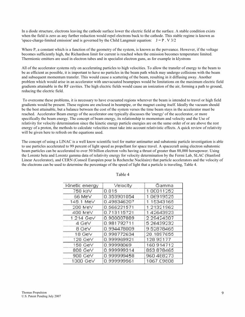
In a diode structure, electrons leaving the cathode surface lower the electric field at the surface. A stable condition exists when the field is zero as any further reduction would repel electrons back to the cathode. This stable regime is known as 'space-charge-limited emission' and is governed by the Child Langmuir equation: J = P . V 3/2 Where P, a constant which is a function of the geometry of the system, is known as the perveance. However, if the voltage becomes sufficiently high, the Richardson limit for current is reached when the emission becomes temperature limited. Thermionic emitters are used in electron tubes and in specialist electron guns, as for example in klystrons All of the accelerator systems rely on accelerating particles to high velocities. To allow the transfer of energy to the beam to be as efficient as possible, it is important to have no particles in the beam path which may undergo collisions with the beam and subsequent momentum transfer. This would cause a scattering of the beam, resulting in it diffusing away. Another problem which would arise in an accelerator with unevacuated beampipes would be limitations on the maximum electric field gradients attainable in the RF cavities. The high electric fields would cause an ionization of the air, forming a path to ground, reducing the electric field. To overcome these problems, it is necessary to have evacuated regions wherever the beam is intended to travel or high field gradients would be present. These regions are enclosed in beampipe, or the magnet casing itself. Ideally the vacuum should be the best attainable, but a balance between the cost of the system verses the time beam stays in the accelerator must be reached. Accelerator Beam energy of the accelerator one typically discusses the 'energy' of the accelerator, or more specifically the beam energy. The concept of beam energy, its relationship to momentum and velocity and the Use of relativity for velocity determination since the kinetic energy particle energies are on the same order of or are above the rest energy of a proton, the methods to calculate velocities must take into account relativistic effects. A quick review of relativity will be given here to refresh on the equations used. The concept of using a LINAC is a well know scientific tool for matter antimatter and subatomic particle investigation is able to use particles accelerated to 99 percent of light speed as propellant for space travel. A spacecraft using electron subatomic beam particles can be accelerated to over 50 billion electron volts having a thrust of greater than 88,000 horsepower. Using the Lorentz beta and Lorentz gamma data of relativity energy for velocity determination by the Fermi Lab, SLAC (Stanford Linear Accelerator), and CERN (Conseil Européen pour la Recherche Nucléaire) that particle accelerators and the velocity of the electrons can be used to determine the percentage of the speed of light that a particle is traveling, Table 4.
Table 4

Thomas Propulsion U.S. Patent Pending July 2007
10
The present invention using a linear particle accelerator follows Albert Einstein’s Law of Relativity E=MC2 , Newton’s Laws of Motion, and data beam energies seen in Fermi lab accelerators as proof that an electron beam energy stream can be accelerated to the speed of light. It can therefore be shown that the kinetic energy of the high velocity electrons having mass, i.e. E=MC2, can be used to propel a spacecraft through outer space. The self contained small, sealed, transportable, autonomous pebble bed nuclear reactor (PBR) will provide >25 Megawatts of electrical energy. The electrical energy from the PBR will be the generator for electrons to the linear particle accelerator. This electrical energy used as a 30 year source of thermionic electrons to the cathode. There are atleast two major advantages for operating a linear particle accelerator in outer space as the vacuum creates very low temperatures (2 degrees above absolute zero) which can be used to keep the LINAC from overheating and burning up. The second reason for operation in space is there are no particles that can get into the wave tube during operation causing unwanted ionization preventing efficient electron subatomic particle acceleration. The thermionic electrons movement away from the cathode will be controlled by a control gate which allows electrons to pass. The control gate will also control forward velocity of the spacecraft by allowing more thermionic electronics to enter the wave tube to be accelerated by the LINAC. An anode close to the control gate accelerates the electrons faster so they can’t be recaptured by control gate. The first of many microwave high energy Klystrons tuned to slightly longer wavelength will accelerate the electrons through the linear particle accelerator. The first stage klystron is used to bring the electrons in alignment with the positive peaks of the base microwave frequency used in the linear accelerator and is called the buncher. From the buncher the electrons enter the wave tube region in the linear accelerator (LINAC) where the electron beam particles are eventually accelerated to 99 percent of light speed. The LINAC uses magnetic stirring guides called drift tubes installed between klystron waveguide microwave power inputs to keep the electron beam energy bunched together preventing them from drifting apart in the linear acceleration waveguide. Each klystron is tuned to a slightly different wavelength to continue pushing the electrons forward through the accelerator using the peaks of the gradually increasing microwave frequency wavelength to move the electrons in a linear forward direction only. The accelerated electron beam particles exit the LINAC with a force equal to or greater than 50 billion electron volts traveling at 663,910,463 miles / hour arriving at the high energy phased array microwave antenna’s located near the exiting LINAC electron beam particles.
MICROWAVE PHASED ARRAY STEERING The accelerated electrons have reached a point where the energy from exciting the linear accelerator can now be used for space craft propulsion. The exciting synchronized beam electrons angular direction of movement from the space craft is steered by changing the phase of the output electro magnetic fields (EMF) waveform. The phased array microwave control electronics will change the peak EMF waveform start time thus shifting the phase angle of the EMF transmitted microwave. The phased array microwave control electronics will change the peak EMF waveform start time thus shifting the phase angle of the EMF transmitted microwave. The phased array microwave EMF positive peak sine waves synchronize with the positive peaks of the electron particle beam containing the high energy near light speed negative charged electron subatomic particles. By changing the time phase output of the microwave peak pulse influences the electro magnetic energy wave front angle to be able to move through a +60 to -60 degree from 0 degree normal microwave radiation pattern. The phased array EMF microwave is synchronized to the microwave force of the near light speed electron particle beam providing a means for changing the spacecrafts speed and direction. The 4 minimum microwave phased array antenna electro magnetic frequencies will work together to create a variable angular pitch virtual waveguide in space for the path of the near light speed propellant electrons. No physical contact is made with the electrons thereby preventing loss of kinetic energy of the electron propellant’s work energy. An equal and opposite force will thereby be applied to the spacecraft according to Newton’s Third Law of Motion. Changing the path angle of the discharged electron beam changes the direction of force on the aft / rear of the spacecraft used as a rudder for steering the spacecraft per Newton’s Three Laws of Motion. The increased energy of the linear particle accelerated electron beam falling under Einstein’s General Theory of Relativity E=MC2 and Special Theory of Relativity.

Thomas Propulsion U.S. Patent Pending July 2007
11
Fig 3
CAPTURE OF ELECTRON PROPELLANT IN SPACE There is a renewable propellant source using the infinite varying concentration of electrons (leptons - e) in space that will be attracted to a moving space craft. The positive charge created by the space craft propulsion can also be used for some protection to the space craft from positive particles in space like protons, some alpha particle, dust, etc. which would be repelled. Electrons (leptons - e) would be attracted and collected by the positive charged coulomb collector ring 43 around the center of the space craft hull as a renewable energy source4. The extremely high energy of the free space electrons will be captured along with the mass of the electrons for increased power needs. The rest of the ships hull 26 is near voltage neutral. Fig. 4
Fig. 4

Thomas Propulsion U.S. Patent Pending July 2007
12
PROPULSION POWER AND ENGINEERING REQUIREMENTS
The interplanetary and interstellar space craft will rely on a 22.5 MW pebble bed nuclear reactor using the heated helium gas from the nuclear reactor as the coolant. The heated gas coolant will be used by a gas turbine generator for the generation of electricity. The pebble bed reactor will use a simple system of adding and removing grapefruit size uranium graphite balls to increase and decrease reactor activity. Helium gas is passed into the reactor and flows over the fuel pebbles in which a chain reaction is taking place. The helium is heated to a temperature of 900 degrees and pressure increases to 69 bars inside the reactor. The heated helium gas flows through to the turbine which in turn drives a generator. The helium gas then goes through to a very effective recuperator which gives up much of its heat to the helium which is just about to re-enter the reactor - pre or re-heating the helium. The lower-energy helium gas is then passed through the pre-intercooler and inter-cooler and low pressure compressor and high pressure compressor before returning to the reactor core at 540 degrees. Vacuum of space and heat exchanger will be used only on the cooling systems throughout the space craft. SSTAR Pebble Bed Reactor, Fig. 4. Below is a diagram example of a Simple Modular High Temperature Gas-cooled Reactor power plant is essentially contained in two interconnected pressure vessels for 22.5 Megawatt. The design can be customized to our spec.
Fig 4

Thomas Propulsion U.S. Patent Pending July 2007
13
Pebble Bed Nuclear Fuel – Minimum of 10 years fuel life Weight of Self Contained Pebble Bed Reactor Fuel for normal operation, the pressure vessel contains a fuel load of 44000 balls, each 60 mm in diameter, Fig. 5. This load consists of 31000 fuel balls containing uranium dioxide particles encased in graphite and silicon carbide. The uranium dioxide particles are less than half a millimeter in size, and there are 1500 of them in one fuel ball, totaling 9 g of uranium, which means that total uranium in one fuel load is approximately (454 lbs.). Approximate weight of self contained pebble bed reactor is (11,200 lbs.) at approximately (10 feet x 10 feet).
Fig 5
Thermal characteristics Helium gas turbine, power klystrons, control electronics, misc. electronics and linear particle accelerator generator with rely on heat in some cases to generate energy and in some cases heat will be an unwanted by product. The temperature of 2 degrees of absolute zero in free vacuum space will be utilized to remove all thermal loads from the space craft by heat exchangers. Radiators can be developed to be deployed and used when and if they are needed to balance the heat load of the propulsion system. They can be designed so they can be deployed during space craft acceleration. Electrical Power requirements Approximately 22.5 MW for the linear accelerator operation, control electronic, crews power needs, radio frequency communication / radar, and phased array microwave rudder system. Structure (Vibration / acoustics) The vibration of the space craft’s linear accelerator will be kept to minimum through the use of high powered superconducting magnets using the vacuum of space to kept the temperature in the safe operating mode. Motors and generator use will be kept to a minimum to reduce noise, vibration, and unwanted RF interference. The crew’s quarters, control and command lab with have a gravitational field due to the continual acceleration during flight. The crew’s quarter will be kept at comfortable temperature from excessive heat by the propulsion unit and additional heat can be pumped into the living quarters by sharing of the heat load from the reactor helium coolant. Helium is an inert gas having 0 reactive components to harm ships personnel.
CONCLUSIONS
The simplicity, cost, and indefinite reusability of a near light speed space craft using an electron linear particle accelerator propulsion engine using thermionic electrons, magnetic wave tubes, radio frequency klystrons, self contained nuclear reactor, and phased shifted microwaves for spacecraft propulsion have endless applications for mankind. A self contained nuclear reactor with a minimum of a 10 year lifetime will supply an electron fuel source of thermionic electrons for a linear particle accelerator and free electrons in space will be used as a renewable propellant source for the space craft. No other propulsion method published to date has covered the realistic possibilities of such an engine capable of interstellar and interstellar travel having the possibility of saving mankind from extinction. The space shuttle will be the best application of this technology.

Thomas Propulsion U.S. Patent Pending July 2007
14
REFERENCES 1 Patent: 5546743, Dr. Paul H. Conner, Dumfries, Va. 2 Mathematical Recreations, Interstellar Travel, Dr. Steve Schaefer, Ph.D. Princeton University (Physics) 3 "Einstein For Dummies", By Dr. Carlos I. Calle, PhD, NASA senior research scientist Pub. Date: June 2005, ISBN: 978-0- 7645-8348-3, Pages: 384 Pages. 4 A new measurement of the electron density in the local interstellar medium, Dr. Brian E. Wood and Dr. Jeffrey L. Linsky 1996 October 17, http://www.journals.uchicago.edu/cgi-bin/resolve?1997ApJ...474L..39WPDF