advanced diffractive optical elements - nanyang...
TRANSCRIPT

Advanced diffractive optical elements
Sergiy Valyukh
Laboratory of Applied Optics,Department of Physics, Chemistry and Biology (IFM)
Linköping University, SE-58183, Linköpinge-mail: [email protected]

Outline
Introduction
Conclusions
LC lenses for autostereoscopic displays
Diffractive reflective liquid crystals elements
Basic principals of liquid crystal diffractive optical elements
Optical projection system for near-to-eye displays
Ellipsometry as a accurate technique for characterization surfaces and materials

IntroductionThe 21st century is the century of the photon!

Introduction
Mechanical systems are relatively heavy and bulky
LC systems are associated with low driving voltage, low energyconsumption and non-mechanical tunability

Diffraction occurring with a single slit Diffraction occurring with two slits (amplitude diffraction grating)
Diffractive optical elements

Single-layer blazed grating with the interface to Air. The diagram shows the diffraction efficiency for the diffracted orders m = 0, 1, and 2. (Material: inorganic glass SSK3).
Two-layers blazed grating with the interface to Air. The diagram shows the diffraction efficiency for the first diffracted order. (Material: inorganic glass SSK3 and polystyrene).
Diffractive optical elements

Fresnel lens
Surface relief profile of the Fresnel lens
Blazed binary approach of the Fresnel lens
Diffractive optical elements

Gradient-index (GRIN) media
Fermat’s principle: the path taken between two points by a ray of light is the path that can be traversed in the least time
Gradient-index lens
Aberrations in a refractive lens
Light ray in a GRIN medium

neff ( x )= x sin αd +neff (0 ) neff ( x )= x2
df+neff ( 0)
neff=1L ∫L
no ne dl
√no2+(ne2− no2)(�n ( l)�k ( l))2
a) Prism (beam steering device)
Liquid crystal optical elementsb) Lens

( )∫ sdielel f+dzf+f=G1) Finding the director distribution
( )2
2211 sincos
21
⎟⎠⎞
⎜⎝⎛
dzd(z)α(z)K+α(z)K=f 33el
EεEε=f odiel
rrˆ
21
f sbottom=f s
top= 12 W sin2(α− α o)
Design of LC OE

2) Calculation of the light propagation2
2∆∆Rλ=D
∫L
2eo
eo
θ(r)n+θ(r)ndrnn
λ=Φ
222 cossin2π
)rθ(n+)rθ(nnn=)r(n
2eo
eoe rrr
222 cossin
d
k(x,y)
X
Yγ
Z
f
Design of LC OE

LC OE controlled with a non-uniform electric field
Fig. 1 Conceptual design and operation of an LC reflection-mode beam steerer. Steering occurs in a plane perpendicular to the electrode length, as shown in the upper portion of the figure.
Fig. 2 Electrode voltage distribution, equal potential lines, and LC director distribution for a 48-um-period blazed grating formed in a 4.8-um LC cell (top). Resulting phase profile for lamda=633 nm (bottom).
From B. Apter, U. Efron, E. Bahat-Treidel, Appl. Opt., 43, 11 (2004)
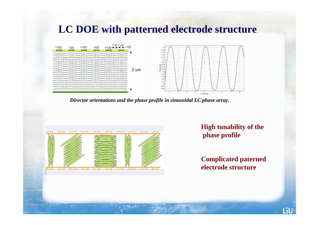
Director orientations and the phase profile in sinusoidal LC phase array.
LC DOE with patterned electrode structure
High tunability of thephase profile
Complicated paterned electrode structure

LC director orientations in an LC cell with the cell gap 5µm and width 30µm. A half of the cell (0-15µm) is under 5V and the resulting phase profile in the LC cell
Fly-back zone
2
0 1 ⎟⎠⎞
⎜⎝⎛
Λ∆
−=Xηη
S. Valyukh, I. Valyukh, V. Chigrinov, Photon. Lett. Pol. 3, 88 (2011).S. Valyukh, V. Chigrinov, SID Digest, 49, p.1691, (2011).S. Valyukh, I. Valyukh, V. Chigrinov, H.S. Kwok, H. Arwin, Appl. Phys. Let. 97, 231120 (2010).S. Valyukh, V. Chigrinov, H. S. Kwok, H. Arwin, Opt. Expr., 20, Issue 14, pp. 15209 (2012).

LC DOE controlled with uniform electric field
LC DOE contained periodic polymer structure
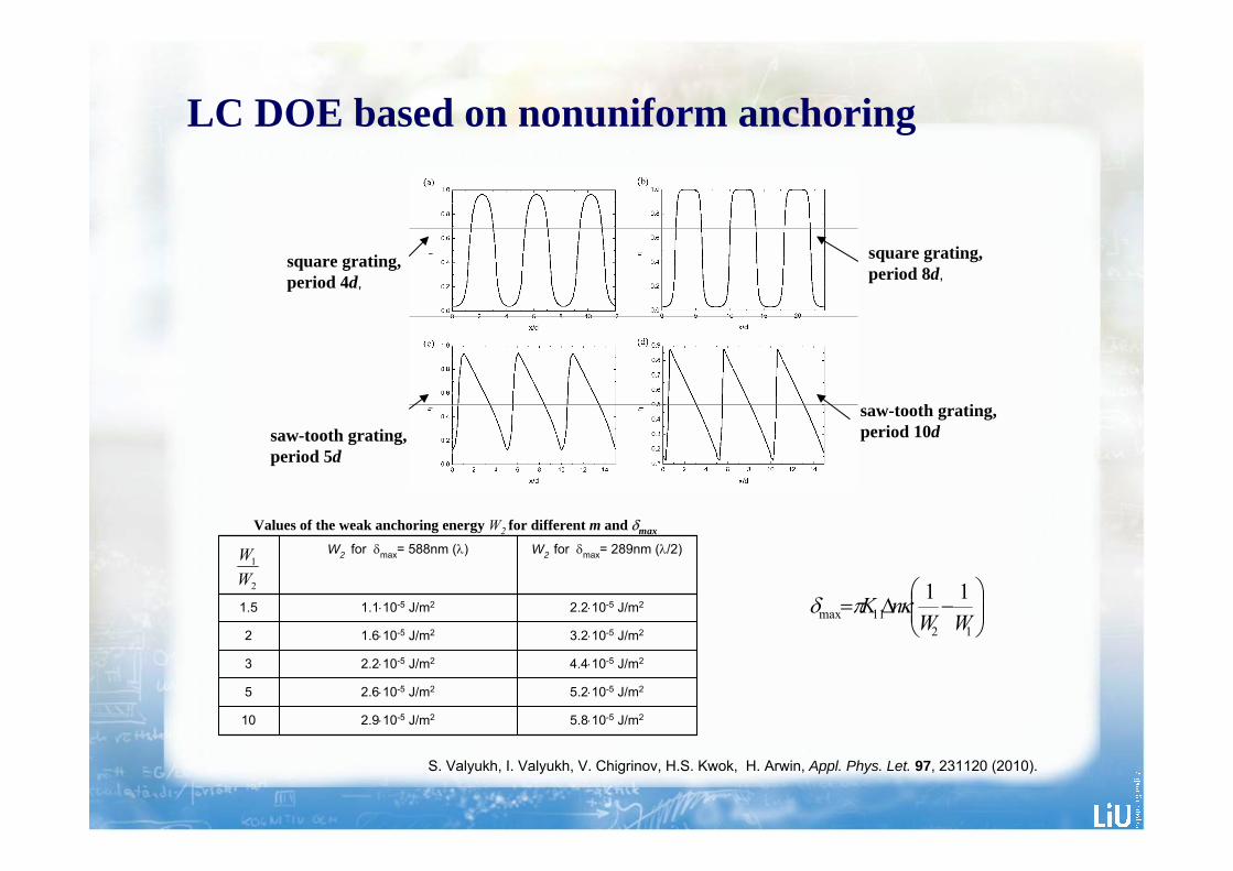
LC DOE based on nonuniform anchoring
⎟⎟⎠
⎞⎜⎜⎝
⎛−∆=
1211max
11WW
nK κπδ
Values of the weak anchoring energy W2 for different m and δmax
5.8⋅10-5 J/m22.9⋅10-5 J/m210
5.2⋅10-5 J/m22.6⋅10-5 J/m25
4.4⋅10-5 J/m22.2⋅10-5 J/m23
3.2⋅10-5 J/m21.6⋅10-5 J/m22
2.2⋅10-5 J/m21.1⋅10-5 J/m21.5
W2 for δmax= 289nm (λ/2) W2 for δmax= 588nm (λ)
2
1
WW
LC DOE based on nonuniform anchoring
square grating,period 4d,
square grating,period 8d,
saw-tooth grating,period 5d
saw-tooth grating,period 10d
S. Valyukh, I. Valyukh, V. Chigrinov, H.S. Kwok, H. Arwin, Appl. Phys. Let. 97, 231120 (2010).

LC DOE based on nonuniform pretilt angle
( )⎟⎟
⎠
⎞
⎜⎜
⎝
⎛−⎟⎟
⎠
⎞⎜⎜⎝
⎛+−
= 1)(
)(sin2
22
22
xdndn
nnnx
o
e
oe
o
δα
η as a function of X/Λ for different values of Λ
oe
effe
nnnn
−
−=η
S. Valyukh, V. Chigrinov, H. S. Kwok, H. Arwin, Opt. Expr., 20, Issue 14, pp. 15209 (2012).

LC DOE based on nonuniform pretilt angle
( )⎟⎟
⎠
⎞
⎜⎜
⎝
⎛−⎟⎟
⎠
⎞⎜⎜⎝
⎛+−
= 1)(
)(sin2
22
22
xdndn
nnnx
o
e
oe
o
δα
99.9%0.04%100d
93.2%1.1%20d
75.6%3.7%8d
54.1%8.6%4d
39.4%12.7%2d
1st order0 order Period
Diffraction efficiency of the grating
S. Valyukh, V. Chigrinov, H. S. Kwok, H. Arwin, Opt. Expr., 20, Issue 14, pp. 15209 (2012).
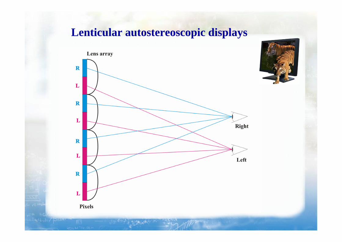
Lenticular autostereoscopic displays

Near-to-eye display
Google’s Project Glass prototype and a hypothetical view

J. D. Smet, A. Avci, R. Beernaert, D. Cuypers and H. D. Smet, “Wrinkle formation in conformable liquid crystal cells for use in a contact lens display”, Proc. 18 thInternational Display Workshop & Asia Displays, pp. 1203-1206, Japan (2011).
Yoneda, Yuka. “Solar Powered Augmented Contact Lenses Cover Your Eye with 100s of LEDs”, inhabitat, 17 March 2010
Augmented Reality in a Contact Lens
Near-to-eye display

Definition of the problem
Requirements for the optical system:
Definition of the problem
1) provide a clear vision of the display image
2) do not distort the image from outside
3) compactness

Definition of the problem
Projection of the display image on the eye
f = abb− a
If b>>a and b>>t, f≈a
fD 1
=

Liquid Crystal Lens
2000 50 0.25 10 dioptersDµm,=R,=∆nµm,=d ≈
)0()(2
effeff ndfxxn +=
( )( )∫−+
=L
oeo
eoeff
lklnnnn
dlnnL
n2222 )()(
1rr
Optical power:( )22
2ndR
ndD∆−
∆=

Cross section of the near eye LCD matched with the LC lens array
Array of Liquid Crystal Lenses
LC lens array
Polarizers Transparent electrodes
Pixels of LCD

Array of Liquid Crystal Lenses
A hypothetical view through the near eye display
%1001 ×⎟⎟⎠
⎞⎜⎜⎝
⎛−=
display
image
SS
T
Area overlapped by the lens (image). This area is semitransparent.
lens (image)
Object
The ray tracing scheme of the object
Domain with an image
The area of the display is divided into domains,in which separate images are generated

Array of Liquid Crystal Lenses
LC lenses are matched with the pixels of LCD
Example in which the lens area is 4 times larger the pixel area
PolarizersTransparent electrodes
Pixels of LCD LC lens array

0.20.4
0.6
0.8
0
1
2
3
0.20.4
0.60.8
Anc
horin
g en
ergy
Wx1
0-4 [J
/m2 ]
Y(mm)
X (mm)
Distributions of the anchoring energy for a positive LC lens
Example. Anchoring distribution
Liquid Crystal Lens based on non-uniform alignment
S. Valyukh, V. Chigrinov, H. S. Kwok, H. Arwin, Opt. Exp., 20, pp. 15209-15221 (2012).
S. Valyukh, I. Valyukh, V. Chigrinov, H. S. Kwok, H. Arwin, Appl. Phys. Lett. 97, 231120 (2010)

Reflective surfaces
Ligh reflected from a uniform flat surface. The angle of reflection does not depend on X.
Ligh reflected from a flat surface having a complex periodic microstracture. The angle of reflection is a function of X.
X
X

Cholesteric liquid crystal lenses
θ θ i r θ θ i r
Incline planar texture of ChLC
ChLC lens
Planar texture of ChLC

Electromagnetic wave (E) after reflection from a chelicoidal non-flat structure
Cholesteric liquid crystal lenses

Spherical PV cell
Folded PV cell
V. Andersson, K. Tvingstedt, O. Inganäs. J. App. Phys. 103, 094520 (2008).
Cholesteric liquid crystal lenses
Reflective flat surfaces with complex periodic microstructures can essentially increase efficiencyof the folded PV cells

Light Scattering from Scarab Beetles
Beetles of the subfamily Rutelinae: a) Chrysophora chrysochlora, b) Chrysina resplendens.
a) b)
View through left-handed circular polarizer View through right-handed circular polarizer

+
⎟⎟⎟⎟⎟⎟
⎠
⎞
⎜⎜⎜⎜⎜⎜
⎝
⎛
+
+
=
⊥
⊥
⊥
ε
εε
εε
ε
00
02
0
002
)(ˆ II
II
z⎟⎟⎟
⎠
⎞
⎜⎜⎜
⎝
⎛−
+ ⊥
0000)2cos()2sin(0)2sin()2cos(
2qzqz
qzqzII εε
qkk rirrr
=−
Reflection from periodical structure
1) High reflection within a certain spectral range
2) Existence of the “blue shift”
3) The reflected light is circular polarized
+
⎟⎟⎟⎟⎟⎟
⎠
⎞
⎜⎜⎜⎜⎜⎜
⎝
⎛
+
+
=
⊥
⊥
⊥
)(00
02
)()(0
002
)()(
)(ˆ
z
zz
zz
z II
II
ε
εε
εε
ε⎟⎟⎟
⎠
⎞
⎜⎜⎜
⎝
⎛−
+ ⊥
0000))(2cos())(2sin(0))(2sin())(2cos(
2)()( zzqzzq
zzqzzqzzII εε
H. Arwin, R. Magnusson, J. Landin, K. Järrendahl Phil. Mag. 92, 1593 (2012)
IIpp ελε ≤≤⊥

Roughness influence
Model of helicoidal periodic and imperfect structure
Z
Y
Z
( ) ( )),()(ˆ),('ˆ 1 zyRzzyR θεθε −=

⎥⎥⎥⎥
⎦
⎤
⎢⎢⎢⎢
⎣
⎡
=
3
2
1
SSSS
S
o
r
oo IISo 900 +=
oo IIS 9001 −=
oo IIS 45452 −+ −=
LR IIS −=3
),(ˆ)(),(ˆ λαλα αα aMfM r=
( )A
o
eA
f 2
2
21)(
αα
απ
α−
−=
),(),(ˆ),( λαλαλα ir SMSrr
=
Roughness influence
Reflection and refraction of incident collimated light show moderate scattering.

dpdpfMffC
M pD
p
p
βλθθβθβλα θ
β
ββγ )),,(,,(ˆ)()(1),(ˆ
max
min
max
min
2∫ ∫=
)(ˆ)(),(ˆ λβλβ ββ tMfM =( )
Bo
eB
f 2
2
21)(
ββ
βπ
β−
−=
Reflection from domains
The curved helicoidal structure can be presented as an ensemble of uncorrelated domains that have flat profiles and different inclinations.
The quasi-periodical helicoidal structure can be presented as an ensemble of uncorrelated domains that are characterized with a distribution of the orientation and pitch

Overall scattering and reflectance
),(ˆ)1(),(ˆ),(ˆ λαµλαµλα γα MMM S −+=
Scattering includes two parts: scattering from the surface and scattering from the ensemble of the domains distributed in orientation and pitch

Schematic setup for ellipsometric measurements
Ellipsometry

The Jones matrix:
Ellipsometry
⎥⎥⎦
⎤
⎢⎢⎣
⎡⎥⎦
⎤⎢⎣
⎡=
⎥⎥⎦
⎤
⎢⎢⎣
⎡iny
inx
outy
outx
EE
JJJJ
EE
2212
2111
⎥⎥⎥⎥
⎦
⎤
⎢⎢⎢⎢
⎣
⎡
=
3
2
1
SSSS
S
o
r
oo IISo 900 +=
oo IIS 9001 −=
oo IIS 45452 −+ −=
LR IIS −=3
The Muller matrix:
ir SMSrr ˆ=

♦ Tunable LC diffractive optical elements have been considered
Conclusions
♦ The optical system consisting of an array of active LC lenses has been reported
♦ The system enables the viewer to see an image formed by a near eye display integrated into glasses or a contact lens.
♦ Cholesteric liquid crystal lenses have been discussed