ads single stub tutorial
DESCRIPTION
ADs tutorial for single stub matchingTRANSCRIPT
Advanced Design System
Instructions for ADS Use at WSU: ADS software runs on windows 2000 and XP platform and is installed on 15 PCs in sloan and six in eme230 North (same as RF Lab.). To start ADS:
1. Sign on the PC. 2. click start > program>Advanced Design System 20002 > Advanced Design System
The following tutorial demonstrates using ADS for designing a single stub matching circuit. You will be introduced to passive components and S-parameter element and fine tuning the circuit. NOTE: You can access this tutorial on the internet at:

2
Tutorial for Automated Design System (ADS)
You Chung Chung Cynthia Furse
January 23, 2001
http://www.engineering.usu.edu/ece/faculty/furse/TUTORIAL/ADS/singlestub/ADSsinglestub.doc
Cynthia Furse Associate Professor Department of Electrical and Computer Engineering Utah State University 4120 Old Main Hill Office: EL152

3
In this tutorial we will see how to use ADS. We see in this tutorial how to do Single-Stub Shunt matching We see how to use Smith Chart and also Rectangular to get matching To Start ADS in the SUN lab •type: “hpads” to run the program If display environment is not matched for ADS, set your environment as following. Add to your .cshrc file: #hpeesof (ads 1.3) config
setenv HPEESOF_DIR /opt/hpeesof set path = ( $path $HPEESOF_DIR/bin) setenv HPEESOF_KEY $HPEESOF_DIR/licenses/hpeesof.key
•source .cshrc •type: “hpads” to run the program To Start ADS in the EM lab (PC)
Double Click on ADS icon: Advanced System Design.

4
Table of Contents 1. Create a NEW Project Directory............................................................................... 4
2. Open a Schematic Window ........................................................................................ 5
3. Get parts and Paste ...................................................................................................... 5
4. Copy/Paste and Move a part ....................................................................................... 6
5. Calculate length and width of MLIN with Line Calculation Tool........................... 7
6. Change Component Parameters................................................................................. 8
7. Add MTEE part, Change width of MTEE and Move Text of a part...................... 9
8. Add Open Circuit Stub (MLOC) ............................................................................. 10
9. Calculate the length of MLOC and Change Parameters of Open Circuit Stub
(MLOC)...................................................................................................................... 11
10. Add Term, R and L.................................................................................................. 12
11. Add S Parameter ....................................................................................................... 13
12. Add MSUB................................................................................................................. 14
13. Saving and Simulation of the Circuit ...................................................................... 15
14. Open a Data Display Window, and Rectangular Plot in the Data Display Window
..................................................................................................................................... 16
15. Select S(1,1)/Plot Magnitude Parameter ................................................................ 17
16. Add Marker on S(1,1) graph.................................................................................... 18
17. Tuning Parameters ................................................................................................... 19
18. Fine Tuning Parameters ........................................................................................... 20
19. Changing Impedance to Admittance....................................................................... 21
20. Tuning with Smith Chart ......................................................................................... 22
21. Matching with Admittance....................................................................................... 23

5
1. Create a NEW Project Directory. • Create a new project by clicking on New Directory icon
• Then, you will have the window below. Click on Length Unit and select ‘micron’. Click
on ‘OK’ on Length Unit window. • Then, Type the directory name that you want. Click ‘OK’
6
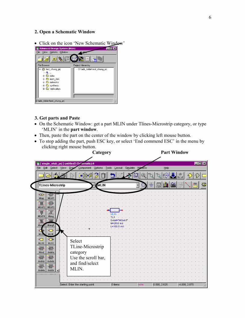
2. Open a Schematic Window • Click on the icon ‘New Schematic Window’
3. Get parts and Paste • On the Schematic Window: get a part MLIN under Tlines-Microstrip category, or type
‘MLIN’ in the part window. • Then, paste the part on the center of the window by clicking left mouse button. • To stop adding the part, push ESC key, or select ‘End commend ESC’ in the menu by
clicking right mouse button. Category Part Window
Select TLine-Microstrip category Use the scroll bar, and find/select MLIN.

7
4. Copy/Paste and Move a part • Highlight/select the part that you want to copy, and click on copy under edit. • Click on left mouse button at the place to paste. • To move a part, select a part and drag the part.
8
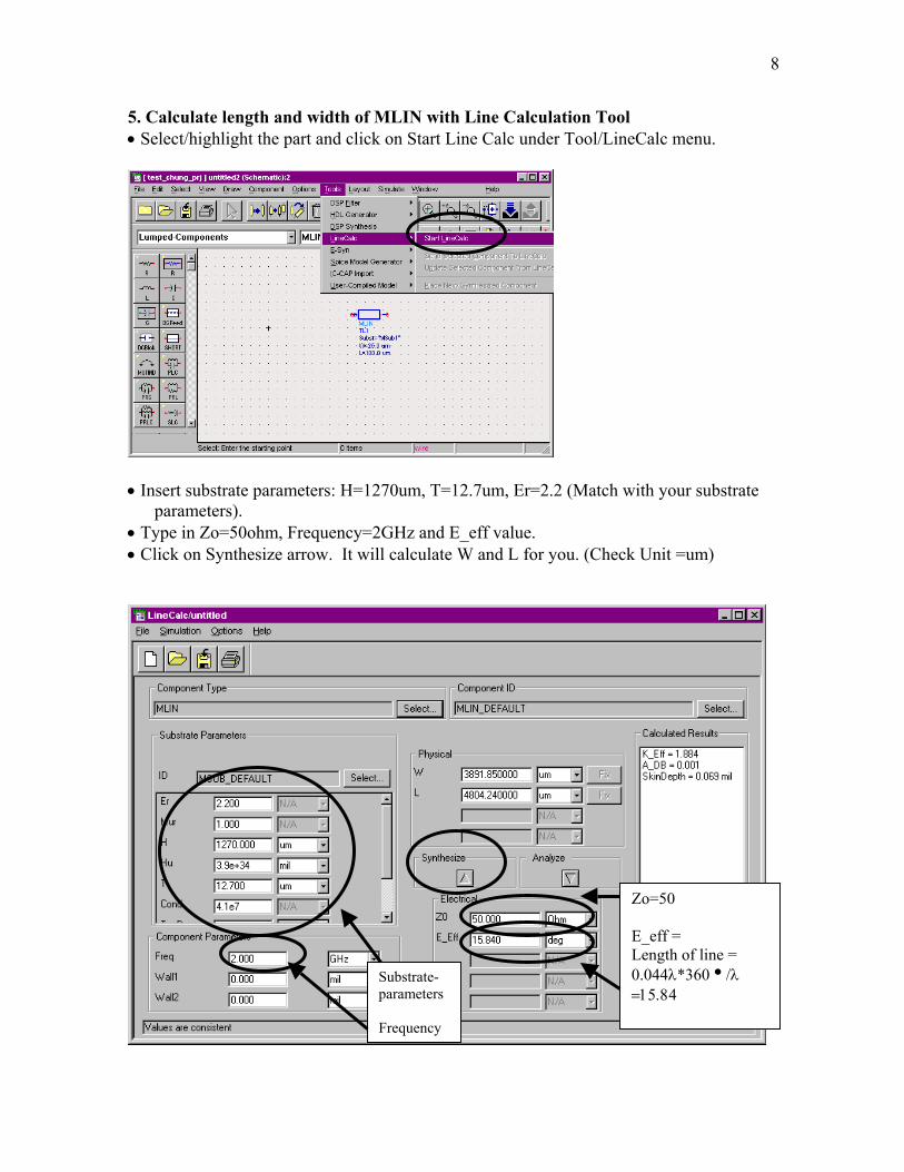
5. Calculate length and width of MLIN with Line Calculation Tool • Select/highlight the part and click on Start Line Calc under Tool/LineCalc menu.
• Insert substrate parameters: H=1270um, T=12.7um, Er=2.2 (Match with your substrate
parameters). • Type in Zo=50ohm, Frequency=2GHz and E_eff value. • Click on Synthesize arrow. It will calculate W and L for you. (Check Unit =um)
Zo=50 E_eff = Length of line = 0.044λ*360i/λ =15.84
Substrate-parameters Frequency

9
6. Change Component Parameters • Either double click on the part or select the part & click right mouse button (Then, click
on ‘Edit component parameters’) • You can change the part parameters on the Schematic Window by click on the value of
W or L. • Change width (W=3891.85um) and length (L=4804.24), from the numbers (W, L) in
LineCalc window.
10
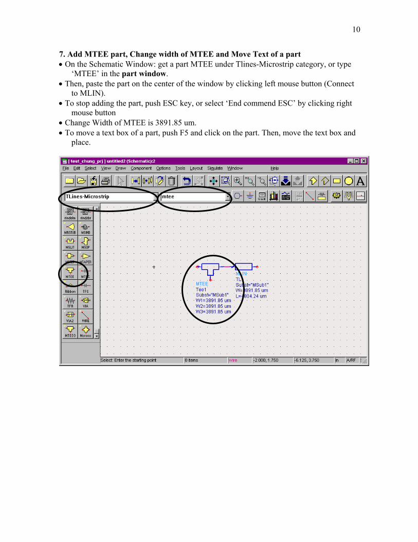
7. Add MTEE part, Change width of MTEE and Move Text of a part • On the Schematic Window: get a part MTEE under Tlines-Microstrip category, or type
‘MTEE’ in the part window. • Then, paste the part on the center of the window by clicking left mouse button (Connect
to MLIN). • To stop adding the part, push ESC key, or select ‘End commend ESC’ by clicking right
mouse button • Change Width of MTEE is 3891.85 um. • To move a text box of a part, push F5 and click on the part. Then, move the text box and
place.

11
8. Add Open Circuit Stub (MLOC) • On the Schematic Window: get a part MLOC under Tlines-Microstrip category, or type
‘MLOC’ in the part window. • Then, connect to the MTEE part. • To stop adding the part, push ESC key, or select ‘End commend ESC’ by clicking right-
side mouse button • Change Width of MLOC (3891.85um). • To rotate a part after paste the part, select/highlight the part and click on Rotate under
Edit menu, or click on Rotation icon. Then, move the mouse and rotate the part/paste. • To move a text box of a part, push F5 and click on the part. Then, move the text box and
place. Rotation Icon
Change Width W=3891.85 um
12
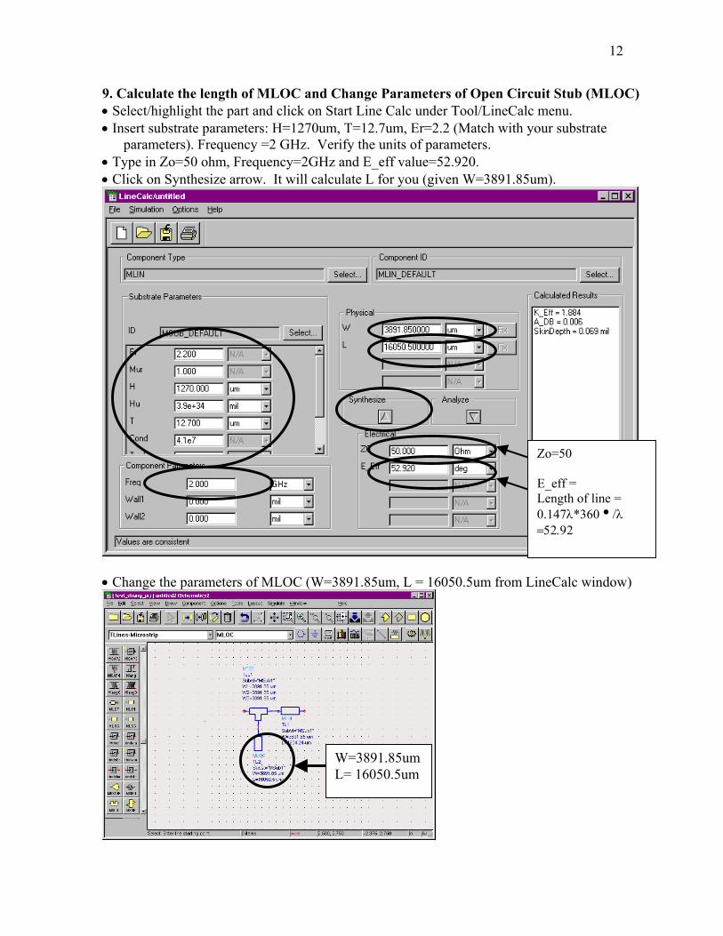
9. Calculate the length of MLOC and Change Parameters of Open Circuit Stub (MLOC) • Select/highlight the part and click on Start Line Calc under Tool/LineCalc menu. • Insert substrate parameters: H=1270um, T=12.7um, Er=2.2 (Match with your substrate
parameters). Frequency =2 GHz. Verify the units of parameters. • Type in Zo=50 ohm, Frequency=2GHz and E_eff value=52.920. • Click on Synthesize arrow. It will calculate L for you (given W=3891.85um).
• Change the parameters of MLOC (W=3891.85um, L = 16050.5um from LineCalc window)
Zo=50 E_eff = Length of line = 0.147λ*360i/λ =52.92
W=3891.85um L= 16050.5um
13
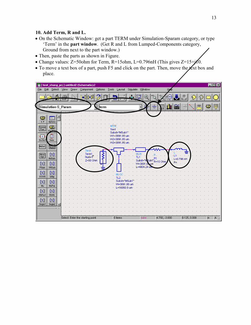
10. Add Term, R and L. • On the Schematic Window: get a part TERM under Simulation-Sparam category, or type
‘Term’ in the part window. (Get R and L from Lumped-Components category, Ground from next to the part window.)
• Then, paste the parts as shown in Figure. • Change values: Z=50ohm for Term, R=15ohm, L=0.796nH (This gives Z=15+j10. • To move a text box of a part, push F5 and click on the part. Then, move the text box and
place.

14
11. Add S Parameter • On the Schematic Window: get a part S P under Simulation-Sparam, or type ‘S_param’
in the part window. • Then, paste the part as shown in Figure. • Change parameters of the S Parameter part. Start = 1GHz, Stop=3GHz and Step=0.2GHz.
Start= 1 GHz Stop= 3 GHz Step =0.2GHz

15
12. Add MSUB • On the Schematic Window: get a part MSUB under Tlines-Microstrip category manually,
or type ‘MSUB’ in the part window. • Then, paste the part as shown in Figure. • Change MSUB parameters of the part. H=1270um, T=12.7um, Er=2.2, Mur=1,
Cond=high value (1E+50), Hu=high value (1E+36um).
e (1E+36um).
Add MSUB
MSUB H=1270um, T=12.7um, Er=2.2, Mur=1, Cond=high value (1E+50), Hu=high valu

16
13. Saving and Simulation of the Circuit • Click on save icon and click on simulate. (If you save your file not in the current project directory, you cannot simulate.)

17
14. Opening a Data Display Window, and Rectangular Plot in the Data Display Window. • Click on New Data Display Window. Then, click on ‘Rectangular Plot’ icon in the data
display window. Place the rectangular plot window in the data display window.
• Data Display Window.

18
15. Select S(1,1)/Plot Magnitude Parameter • Select S(1,1) parameter, and click on ADD. • Select Magnitude option in Complex Data window. Click on ‘OK’. • Click on ‘OK’ on Plot Trace & Attributes window.

19
16. Adding Marker on S(1,1) graph. • Click on New under Marker menu, and click on the point on the graph where you want to
put a marker. (Put it on 2GHz.)

20
17. Tuning Parameters. • Select/highlight the MLIN part in the center of Schematic window, and Click on Turn
Parameters. • Select only L parameter on Text part of MLIN by clicking on L.
21
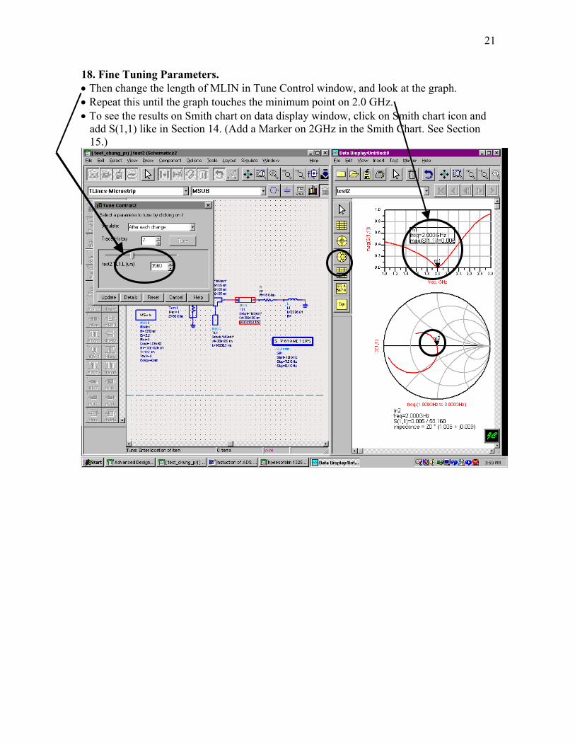
18. Fine Tuning Parameters. • Then change the length of MLIN in Tune Control window, and look at the graph. • Repeat this until the graph touches the minimum point on 2.0 GHz. • To see the results on Smith chart on data display window, click on Smith chart icon and
add S(1,1) like in Section 14. (Add a Marker on 2GHz in the Smith Chart. See Section 15.)
22
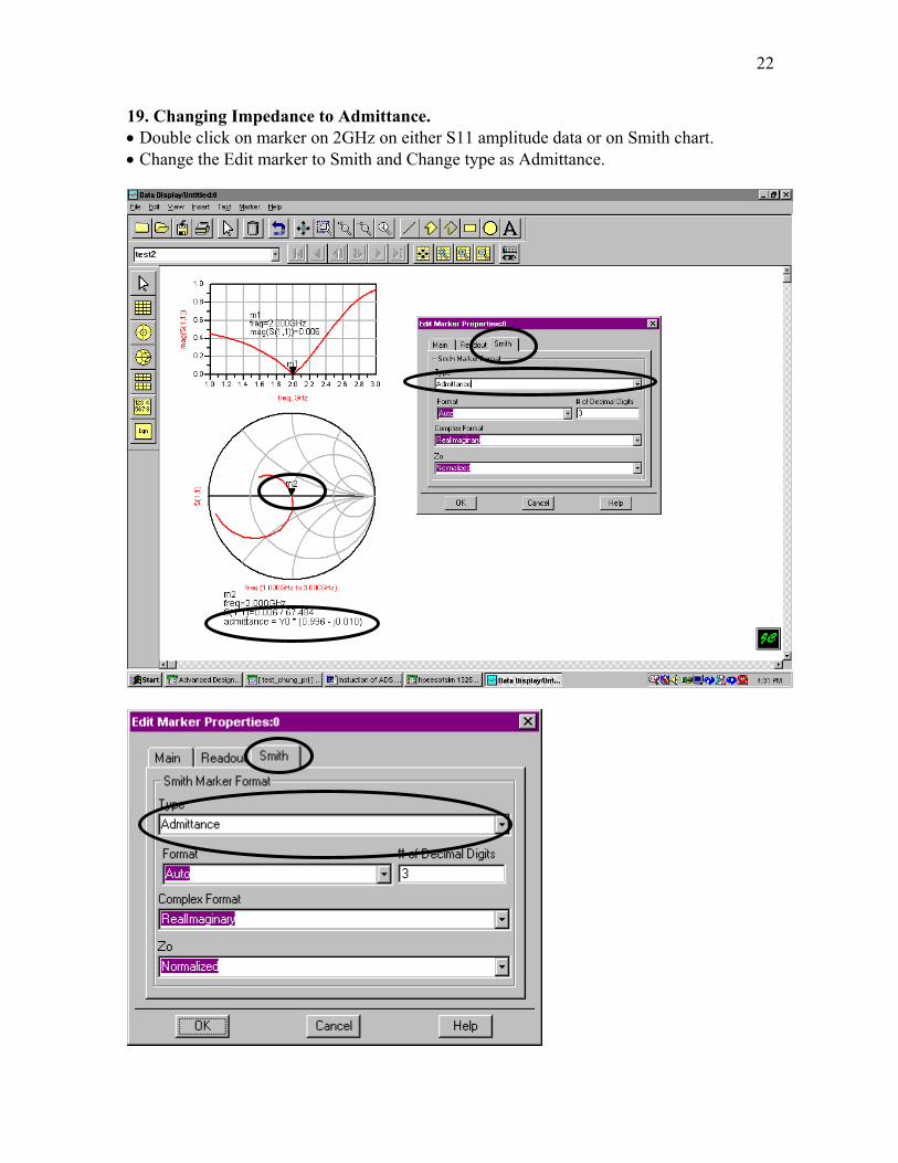
19. Changing Impedance to Admittance. • Double click on marker on 2GHz on either S11 amplitude data or on Smith chart. • Change the Edit marker to Smith and Change type as Admittance.

23
20. Tuning with Smith Chart • If you are using Smith chart instead of using S11 amplitude data, control length of MLIN
until the real part of the admittance is 1. • Then change the length of MLOC until the imaginary part of admittance is 0. • After matching the length of MLIN, the point on 2GHz should be at the center.
24
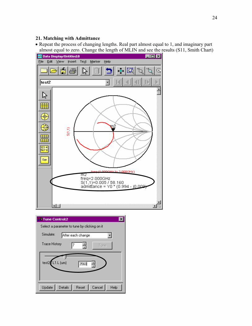
21. Matching with Admittance • Repeat the process of changing lengths. Real part almost equal to 1, and imaginary part
almost equal to zero. Change the length of MLIN and see the results (S11, Smith Chart)