adding new hardware for avaya servers and gateways
TRANSCRIPT
Adding New Hardware for Avaya Servers and Gateways
03-300684Issue 3
Release 5.0January 2008

© 2008 Avaya Inc.All Rights Reserved.
NoticeWhile reasonable efforts were made to ensure that the information in this document was complete and accurate at the time of printing, Avaya Inc. can assume no liability for any errors. Changes and corrections to the information in this document may be incorporated in future releases.For full support information, please see the complete document, Avaya Support Notices for Hardware Documentation, document number03-600759.To locate this document on our Web site, simply go to http://www.avaya.com/support and search for the document number in the search box.
Documentation disclaimerAvaya Inc. is not responsible for any modifications, additions, or deletions to the original published version of this documentation unless such modifications, additions, or deletions were performed by Avaya. Customer and/or End User agree to indemnify and hold harmless Avaya, Avaya's agents, servants and employees against all claims, lawsuits, demands and judgments arising out of, or in connection with, subsequent modifications, additions or deletions to this documentation to the extent made by the Customer or End User.
Link disclaimerAvaya Inc. is not responsible for the contents or reliability of any linked Web sites referenced elsewhere within this documentation, and Avaya does not necessarily endorse the products, services, or information described or offered within them. We cannot guarantee that these links will work all of the time and we have no control over the availability of the linked pages.
WarrantyAvaya Inc. provides a limited warranty on this product. Refer to your sales agreement to establish the terms of the limited warranty. In addition, Avaya’s standard warranty language, as well as information regarding support for this product, while under warranty, is available through the following Web site:http://www.avaya.com/support.
CopyrightExcept where expressly stated otherwise, the Product is protected by copyright and other laws respecting proprietary rights. Unauthorized reproduction, transfer, and or use can be a criminal, as well as a civil, offense under the applicable law.
Avaya supportAvaya provides a telephone number for you to use to report problems or to ask questions about your product. The support telephone number is 1-800-242-2121 in the United States. For additional support telephone numbers, see the Avaya Web site: http://www.avaya.com/support.
Issue 3 January 2008 3
Chapter 1: Introduction . . . . . . . . . . . . . . . . . . . . . . . . . . . 9Audience . . . . . . . . . . . . . . . . . . . . . . . . . . . . . . . . . . . . . . . . 9Using this documentation. . . . . . . . . . . . . . . . . . . . . . . . . . . . . . . 9
Chapter 2: IP connectivity hardware . . . . . . . . . . . . . . . . . . . 11Installing the circuit packs . . . . . . . . . . . . . . . . . . . . . . . . . . . . . . 11Installing and administering IP connectivity hardware . . . . . . . . . . . . . . . 12
TN799DP Control LAN . . . . . . . . . . . . . . . . . . . . . . . . . . . . . . 12Checking your shipment . . . . . . . . . . . . . . . . . . . . . . . . . . . 13Installing a TN799DP C-LAN . . . . . . . . . . . . . . . . . . . . . . . . . 13Installing the cables . . . . . . . . . . . . . . . . . . . . . . . . . . . . . . 14Installing the circuit packs . . . . . . . . . . . . . . . . . . . . . . . . . . 15Administering the TN799DP . . . . . . . . . . . . . . . . . . . . . . . . . 15Testing the external connection to the LAN . . . . . . . . . . . . . . . . . 16
TN2302AP IP Media Processor . . . . . . . . . . . . . . . . . . . . . . . . . . 17Checking your shipment . . . . . . . . . . . . . . . . . . . . . . . . . . . 18Installing a TN2302AP IP Media Processor . . . . . . . . . . . . . . . . . 18Installing the cables . . . . . . . . . . . . . . . . . . . . . . . . . . . . . . 19Installing the circuit packs . . . . . . . . . . . . . . . . . . . . . . . . . . 20Administering the IP Media Processor . . . . . . . . . . . . . . . . . . . 21Testing the external connection to the LAN . . . . . . . . . . . . . . . . . 22Verifying active call status . . . . . . . . . . . . . . . . . . . . . . . . . . 22
TN2501AP Voice announcements over LAN (VAL) . . . . . . . . . . . . . . . 22Installing a TN2501AP VAL . . . . . . . . . . . . . . . . . . . . . . . . . . 23Testing the external connection to the LAN . . . . . . . . . . . . . . . . . 26
TN2602AP IP Media Resource 320 . . . . . . . . . . . . . . . . . . . . . . . . 26Installing the TN2602AP Media Resource 320 . . . . . . . . . . . . . . . . 28Checking your shipment . . . . . . . . . . . . . . . . . . . . . . . . . . . 28Installing a TN2602AP IP Media Resource 320. . . . . . . . . . . . . . . . 29Installing the cables . . . . . . . . . . . . . . . . . . . . . . . . . . . . . . 30Installing the circuit packs . . . . . . . . . . . . . . . . . . . . . . . . . . 31Verifying installation and voice channels . . . . . . . . . . . . . . . . . . 31Administering the TN2602AP circuit pack . . . . . . . . . . . . . . . . . . 32Testing the external connection to the LAN . . . . . . . . . . . . . . . . . 33Verifying active call status . . . . . . . . . . . . . . . . . . . . . . . . . . 33Testing the circuit pack . . . . . . . . . . . . . . . . . . . . . . . . . . . . 34Upgrading firmware (if necessary) . . . . . . . . . . . . . . . . . . . . . . 34
Firmware upgrades . . . . . . . . . . . . . . . . . . . . . . . . . . . . . . . . 34Replacing the I/O cables . . . . . . . . . . . . . . . . . . . . . . . . . . . . . 34
Contents
Contents
4 Adding New Hardware for Avaya Servers and Gateways
Chapter 3: Adding hard drives and power supplies to S8730 Servers . 37Installing an additional hard drive . . . . . . . . . . . . . . . . . . . . . . . . . . 37Installing an additional power supply . . . . . . . . . . . . . . . . . . . . . . . . 39
Chapter 4: Trunks and lines . . . . . . . . . . . . . . . . . . . . . . . . 43List of analog and digital trunk and line circuit packs . . . . . . . . . . . . . . . 43Adding TN464HP/TN2464CP with echo cancellation . . . . . . . . . . . . . . . . 45Adding CO, FX, WATS, and PCOL . . . . . . . . . . . . . . . . . . . . . . . . . . 46Adding DID trunks . . . . . . . . . . . . . . . . . . . . . . . . . . . . . . . . . . 47Adding Analog Tie trunks . . . . . . . . . . . . . . . . . . . . . . . . . . . . . . 47Adding digital DS1 Tie trunks and OPS . . . . . . . . . . . . . . . . . . . . . . . 49Adding TTC Japan 2-Mbit trunk . . . . . . . . . . . . . . . . . . . . . . . . . . . 50Adding CAMA/E911 trunk . . . . . . . . . . . . . . . . . . . . . . . . . . . . . . . 50
Installing the circuit pack . . . . . . . . . . . . . . . . . . . . . . . . . . . . . 52Adding the trunks . . . . . . . . . . . . . . . . . . . . . . . . . . . . . . . . . 52Changing the feature access code . . . . . . . . . . . . . . . . . . . . . . . . 52Changing the ARS digit analysis . . . . . . . . . . . . . . . . . . . . . . . . . 53Changing the route patterns . . . . . . . . . . . . . . . . . . . . . . . . . . . 53Changing the CAMA numbering and class of restriction . . . . . . . . . . . 54
Adding ISDN—PRI . . . . . . . . . . . . . . . . . . . . . . . . . . . . . . . . . . 55North American . . . . . . . . . . . . . . . . . . . . . . . . . . . . . . . . . . 55International . . . . . . . . . . . . . . . . . . . . . . . . . . . . . . . . . . . . 55Adding circuit packs. . . . . . . . . . . . . . . . . . . . . . . . . . . . . . . . 55Connecting cables . . . . . . . . . . . . . . . . . . . . . . . . . . . . . . . . . 56Administering the circuit pack . . . . . . . . . . . . . . . . . . . . . . . . . . 56Resolving alarms . . . . . . . . . . . . . . . . . . . . . . . . . . . . . . . . . 56Saving translations . . . . . . . . . . . . . . . . . . . . . . . . . . . . . . . . 56
Chapter 5: Port networks . . . . . . . . . . . . . . . . . . . . . . . . . . 57Installing a G650 Media Gateway . . . . . . . . . . . . . . . . . . . . . . . . . . 58Installing the IPSI circuit pack . . . . . . . . . . . . . . . . . . . . . . . . . . . . 58Assigning IP addresses to the IPSI circuit packs . . . . . . . . . . . . . . . . . . 58Using static addressing . . . . . . . . . . . . . . . . . . . . . . . . . . . . . . . 59
Clearing the ARP cache on the laptop . . . . . . . . . . . . . . . . . . . . . . 59Logging into the IPSI . . . . . . . . . . . . . . . . . . . . . . . . . . . . . . . 60Setting the control interface . . . . . . . . . . . . . . . . . . . . . . . . . . . 60Setting the VLAN and diffserv parameters. . . . . . . . . . . . . . . . . . . . 61
Using DHCP addressing . . . . . . . . . . . . . . . . . . . . . . . . . . . . . . . 62
Contents
Issue 3 January 2008 5
Administering the location assignment . . . . . . . . . . . . . . . . . . . . . 62Setting the switch ID. . . . . . . . . . . . . . . . . . . . . . . . . . . . . . . . 63Setting the cabinet number . . . . . . . . . . . . . . . . . . . . . . . . . . . . 64Resetting the IPSI . . . . . . . . . . . . . . . . . . . . . . . . . . . . . . . . . 65
Administering the port network . . . . . . . . . . . . . . . . . . . . . . . . . . . 66Adding IPSI translations to Communication Manager . . . . . . . . . . . . . . . 66
Set IPSI duplication (duplicated control network only) . . . . . . . . . . . . . 67Setting alarm activation level . . . . . . . . . . . . . . . . . . . . . . . . . . 68Verifying IPSI translations . . . . . . . . . . . . . . . . . . . . . . . . . . . . 69Verifying IPSI connectivity . . . . . . . . . . . . . . . . . . . . . . . . . . . . 69
Installing additional circuit packs . . . . . . . . . . . . . . . . . . . . . . . . . . 69
Chapter 6: Adjuncts and peripherals. . . . . . . . . . . . . . . . . . . . 71Terminal server installation . . . . . . . . . . . . . . . . . . . . . . . . . . . . . . 71
Installing and administering the terminal server . . . . . . . . . . . . . . . . 72Distance limits . . . . . . . . . . . . . . . . . . . . . . . . . . . . . . . . . 73Cable connection diagram . . . . . . . . . . . . . . . . . . . . . . . . . . 73Making the connections . . . . . . . . . . . . . . . . . . . . . . . . . . . . 74Administering the IOLAN+ . . . . . . . . . . . . . . . . . . . . . . . . . . 75Potential failure scenarios and repair actions . . . . . . . . . . . . . . . . 82
Administering IP node names . . . . . . . . . . . . . . . . . . . . . . . . . . 83Administering IP services . . . . . . . . . . . . . . . . . . . . . . . . . . . . . 83
Call detail recording (CDR) . . . . . . . . . . . . . . . . . . . . . . . . . . . . . . 84Connecting CDR Equipment . . . . . . . . . . . . . . . . . . . . . . . . . . . 84Administering CDR data collection . . . . . . . . . . . . . . . . . . . . . . . 85Administering CDR parameters . . . . . . . . . . . . . . . . . . . . . . . . . 86Testing the switch-to-adjunct link . . . . . . . . . . . . . . . . . . . . . . . . 86
Reliable Data Transport Tool (RDTT) Package. . . . . . . . . . . . . . . . . . . . 86Contents of the RDTT . . . . . . . . . . . . . . . . . . . . . . . . . . . . . . . 87Downloading the tool . . . . . . . . . . . . . . . . . . . . . . . . . . . . . . . 87Installing RDTT . . . . . . . . . . . . . . . . . . . . . . . . . . . . . . . . . . 87Administering RDTT . . . . . . . . . . . . . . . . . . . . . . . . . . . . . . . 88Related Topics . . . . . . . . . . . . . . . . . . . . . . . . . . . . . . . . . . . 88
Wideband endpoints. . . . . . . . . . . . . . . . . . . . . . . . . . . . . . . . . . 88Nonsignaling configuration . . . . . . . . . . . . . . . . . . . . . . . . . . . . 88Signaling configuration . . . . . . . . . . . . . . . . . . . . . . . . . . . . . . 89
Multimedia call handling (MMCH) . . . . . . . . . . . . . . . . . . . . . . . . . . 92Connecting the endpoints. . . . . . . . . . . . . . . . . . . . . . . . . . . . . 92
Administering the system . . . . . . . . . . . . . . . . . . . . . . . . . . 93Administering the endpoints . . . . . . . . . . . . . . . . . . . . . . . . . 93
Contents
6 Adding New Hardware for Avaya Servers and Gateways
Administering one number complex . . . . . . . . . . . . . . . . . . . . . 93Expansion services module. . . . . . . . . . . . . . . . . . . . . . . . . . . . 94
ESM installation . . . . . . . . . . . . . . . . . . . . . . . . . . . . . . . . 94Administration . . . . . . . . . . . . . . . . . . . . . . . . . . . . . . . . . . . 95Place test call . . . . . . . . . . . . . . . . . . . . . . . . . . . . . . . . . . . 96Troubleshooting . . . . . . . . . . . . . . . . . . . . . . . . . . . . . . . . . . 96
Printers . . . . . . . . . . . . . . . . . . . . . . . . . . . . . . . . . . . . . . . . . 96Connecting printers using TCP/IP . . . . . . . . . . . . . . . . . . . . . . . . 96
Task list. . . . . . . . . . . . . . . . . . . . . . . . . . . . . . . . . . . . . 97Administering adjunct parameters . . . . . . . . . . . . . . . . . . . . . . 97Using the downloadable reliable session-layer protocol (RSP) tool . . . . 98
DS1/T1 CPE loopback jack . . . . . . . . . . . . . . . . . . . . . . . . . . . . . . 98Installing a loopback jack . . . . . . . . . . . . . . . . . . . . . . . . . . . . 99
With a smart jack. . . . . . . . . . . . . . . . . . . . . . . . . . . . . . . . 99Without a smart jack . . . . . . . . . . . . . . . . . . . . . . . . . . . . . . 100
Administering the loopback jack . . . . . . . . . . . . . . . . . . . . . . . . . 100Loopback testing with a smart jack . . . . . . . . . . . . . . . . . . . . . . . 101
Testing the DS1 span from the ICSU to the loopback jack . . . . . . . . . 101Restoring DS1 administration. . . . . . . . . . . . . . . . . . . . . . . . . 106Releasing the DS1 circuit pack . . . . . . . . . . . . . . . . . . . . . . . . 107Testing the DS1 span from the smart jack to the network interfacetermination or fiber multiplexer (MUX) . . . . . . . . . . . . . . . . . . . 107
Testing the DS1 span from the loopback jack to the smart jack . . . . . . 108Testing a loopback jack without a smart jack . . . . . . . . . . . . . . . . . . 112Configurations using fiber multiplexers . . . . . . . . . . . . . . . . . . . . . 115
External modems . . . . . . . . . . . . . . . . . . . . . . . . . . . . . . . . . . . 116Hardware required when configuring modems . . . . . . . . . . . . . . . . . 116Paradyne COMSPHERE 3810 Plus and 3811 Plus . . . . . . . . . . . . . . . . 117
Configuring the 3810 Plus and 3811 Plus modems . . . . . . . . . . . . . 117Paradyne COMSPHERE 3910 . . . . . . . . . . . . . . . . . . . . . . . . . . . 117
Configuring the 3910 for CMS. . . . . . . . . . . . . . . . . . . . . . . . . 118Multi-Tech MT5634ZBA-USB-V92 . . . . . . . . . . . . . . . . . . . . . . . . 118
Configuring the MT5634ZBA-USB-V92 modem . . . . . . . . . . . . . . . 118Multi-Tech MT5634ZBA-V92-GLOBAL . . . . . . . . . . . . . . . . . . . . . . 118Administration . . . . . . . . . . . . . . . . . . . . . . . . . . . . . . . . . . . 119
ISDN converters and adapters . . . . . . . . . . . . . . . . . . . . . . . . . . . . 119Converters for single-carrier cabinets . . . . . . . . . . . . . . . . . . . . . . 120
PRI-to-DASS and PRI-to-DPNSS converters . . . . . . . . . . . . . . . . 120PRI-to-BRI converter. . . . . . . . . . . . . . . . . . . . . . . . . . . . . . 121
Converters for multicarrier cabinets . . . . . . . . . . . . . . . . . . . . . . . 122
Contents
Issue 3 January 2008 7
PRI-to-DASS and PRI-to-DPNSS converters . . . . . . . . . . . . . . . . . 122PRI-to-BRI converter. . . . . . . . . . . . . . . . . . . . . . . . . . . . . . 123
Busy tone disconnect equipment fornon-U.S. installations . . . . . . . . . . . . . . . . . . . . . . . . . . . . . . . . 124
909A/B universal coupler . . . . . . . . . . . . . . . . . . . . . . . . . . . . . . . 124Malicious call trace . . . . . . . . . . . . . . . . . . . . . . . . . . . . . . . . . . 128Music-on-hold . . . . . . . . . . . . . . . . . . . . . . . . . . . . . . . . . . . . . 129
Registered music source . . . . . . . . . . . . . . . . . . . . . . . . . . . 131Nonregistered music source . . . . . . . . . . . . . . . . . . . . . . . . . 131Unregistered Music Source on a G700 or G350 Media Gateway . . . . . . 134Registered Music Source on a G700 or G350 Media Gateway . . . . . . . 136
Paging and announcement equipment. . . . . . . . . . . . . . . . . . . . . . . . 137Loudspeaker paging. . . . . . . . . . . . . . . . . . . . . . . . . . . . . . . . 137
Loudspeaker paging without paging adapter . . . . . . . . . . . . . . . . 137Loudspeaker paging access without universal coupler . . . . . . . . . . 138Loudspeaker paging with universal coupler . . . . . . . . . . . . . . . . . 139
ESPA radio paging. . . . . . . . . . . . . . . . . . . . . . . . . . . . . . . . . 140External ringing . . . . . . . . . . . . . . . . . . . . . . . . . . . . . . . . . . 141Queue warning indicator . . . . . . . . . . . . . . . . . . . . . . . . . . . . . 141Loudspeaker paging. . . . . . . . . . . . . . . . . . . . . . . . . . . . . . . . 142
Adjunct information sources . . . . . . . . . . . . . . . . . . . . . . . . . . . . . 143Call Management System . . . . . . . . . . . . . . . . . . . . . . . . . . . . . 143INTUITY AUDIX Messaging Systems . . . . . . . . . . . . . . . . . . . . . . . 144Avaya Modular Messaging System . . . . . . . . . . . . . . . . . . . . . . . . 144ASAI and DEFINITY LAN Gateway . . . . . . . . . . . . . . . . . . . . . . . . 144Avaya Interactive Response . . . . . . . . . . . . . . . . . . . . . . . . . . . 144Avaya Extension to Cellular. . . . . . . . . . . . . . . . . . . . . . . . . . . . 145Property Management Systems . . . . . . . . . . . . . . . . . . . . . . . . . 145Call Accounting Systems . . . . . . . . . . . . . . . . . . . . . . . . . . . . . 145DEFINITY Wireless Business System . . . . . . . . . . . . . . . . . . . . . . 145
Index . . . . . . . . . . . . . . . . . . . . . . . . . . . . . . . . . . 147

Contents
8 Adding New Hardware for Avaya Servers and Gateways
Issue 3 January 2008 9
Chapter 1: Introduction
Use this book to add hardware to an existing Avaya S8XXX Server configuration. Hardware includes circuit packs for existing media gateways, new media gateways that make up new port networks, and adjunct or peripheral equipment. It also includes additional hard drives and power supplies that may be installed on S8730 Servers.
This book includes the following information:
● IP connectivity hardware on page 11
- Installing the circuit packs on page 11
- Installing and administering IP connectivity hardware on page 12
● Adding hard drives and power supplies to S8730 Servers on page 37
● Trunks and lines on page 43
● Port networks on page 57
● Adjuncts and peripherals on page 71
AudienceThis documentation is for the following audiences:
● Technical support representatives
● Authorized Business Partners
Using this documentationUse this documentation as a guide to install and administer the added hardware. For more information about a particular task, see the index or table of contents to locate the page number where the information is described.
You can download the latest version of this documentation from the Avaya Support Web site (http://support.avaya.com). You must have access to the Internet and a copy of Adobe Reader installed on your personal computer.
Avaya makes all possible efforts to ensure that the information in this book is complete and accurate. However, information can change after we publish this documentation. Therefore, the Avaya Support Web site might also contain new product information and updates to the

10 Adding New Hardware for Avaya Servers and Gateways
information in this book. You can also download these updates from the Avaya Support Web site.
Issue 3 January 2008 11
Chapter 2: IP connectivity hardware
This chapter provides procedures for:
● Installing the circuit packs on page 11
● Installing and administering IP connectivity hardware on page 12.
Note:Note: If a circuit pack requires a right-to-use fee for a particular feature, the customer
must have a license file to enable the feature.
When you install additional features or equipment, you might need to install additional circuit packs. Use the following general procedure when adding features or equipment that require adding circuit packs.
1. Log in to the server using a services log in.
Note:Note: S8700-series Servers: For an S8700-series Server, you must log into the active
server to access SAT commands. Use a terminal emulation application, such as Avaya Terminal Emulation, or Avaya Site Administration.
2. Install the TN circuit pack into the media gateway or carrier (if MCC1).
3. Do the minimally required administration so that Avaya Communication Manager recognizes the circuit pack.
4. Log off the server after the addition and any required administration is complete.
For more information about further administering circuit packs and other equipment, see the Administrator Guide for Avaya Communication Manager (03-300509).
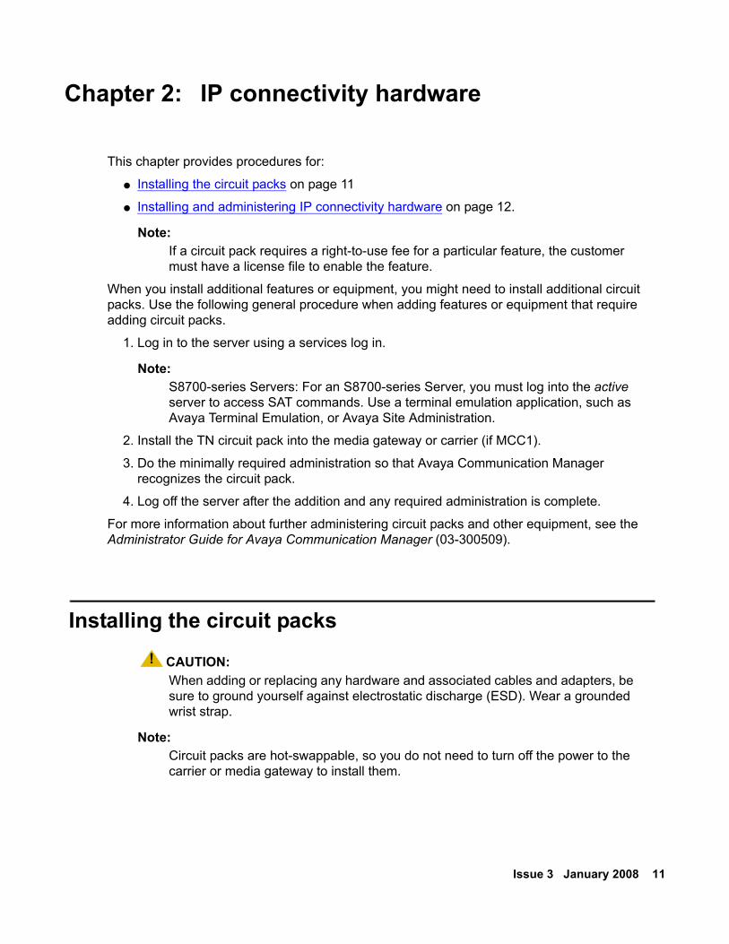
Installing the circuit packs! CAUTION:
CAUTION: When adding or replacing any hardware and associated cables and adapters, be sure to ground yourself against electrostatic discharge (ESD). Wear a grounded wrist strap.
Note:Note: Circuit packs are hot-swappable, so you do not need to turn off the power to the
carrier or media gateway to install them.
12 Adding New Hardware for Avaya Servers and Gateways
Note:Note: To properly seat a circuit pack, push firmly on the front of the faceplate until the
latch reaches the bottom rail of the carrier. Then close the latch until it is fully engaged.
To install a TN circuit pack.
1. Insert the circuit pack into any port slot. If the circuit pack was assigned a slot location, put it in the assigned slot.
2. Type list configuration all and press Enter to verify that the system recognizes the newly installed circuit pack(s).
Installing and administering IP connectivity hardwareThere are several port circuit packs that are used specifically for IP connectivity. This section provides information on installing a:
● TN799DP Control LAN on page 12
● TN2302AP IP Media Processor on page 17
● TN2501AP Voice announcements over LAN (VAL) on page 22
● TN2602AP IP Media Resource 320 on page 26
TN799DP Control LAN The TN799DP Control LAN circuit pack serves several purposes:
● A connection for the signaling (telephone) network to the customer’s data network for IP telephones.
● A source board for downloading firmware to circuit packs having the P designation.
● An IP interface for adjuncts such as Intuity Audix
● An IP interface for DCS connection with another Avaya configuration.
See the Hardware Description and Reference for Avaya Communication Manager (555-245-207) for more information.
Check the firmware vintage and upgrade availability for the TN799DP circuit pack on the Avaya Support Web site: http://support.avaya.com.
The following sections describe the process:
● Checking your shipment on page 13
● Installing a TN799DP C-LAN on page 13
Issue 3 January 2008 13
● Installing the cables on page 14
● Installing the circuit packs on page 15
● Administering the TN799DP on page 15
● Testing the external connection to the LAN on page 16
Checking your shipment
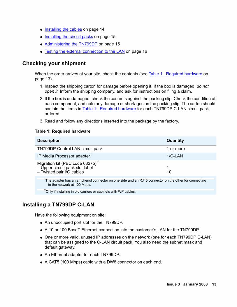
When the order arrives at your site, check the contents (see Table 1: Required hardware on page 13).
1. Inspect the shipping carton for damage before opening it. If the box is damaged, do not open it. Inform the shipping company, and ask for instructions on filing a claim.
2. If the box is undamaged, check the contents against the packing slip. Check the condition of each component, and note any damage or shortages on the packing slip. The carton should contain the items in Table 1: Required hardware for each TN799DP C-LAN circuit pack ordered.
3. Read and follow any directions inserted into the package by the factory.
Installing a TN799DP C-LAN
Have the following equipment on site:
● An unoccupied port slot for the TN799DP.
● A 10 or 100 BaseT Ethernet connection into the customer’s LAN for the TN799DP.
● One or more valid, unused IP addresses on the network (one for each TN799DP C-LAN) that can be assigned to the C-LAN circuit pack. You also need the subnet mask and default gateway.
● An Ethernet adapter for each TN799DP.
● A CAT5 (100 Mbps) cable with a DW8 connector on each end.
Table 1: Required hardware
Description Quantity
TN799DP Control LAN circuit pack 1 or more
IP Media Processor adapter1 1/C-LAN
Migration kit (PEC code 63275):2 – Upper circuit pack slot label– Twisted pair I/O cables
110
1The adapter has an amphenol connector on one side and an RJ45 connector on the other for connecting to the network at 100 Mbps.
2Only if installing in old carriers or cabinets with WP cables.
14 Adding New Hardware for Avaya Servers and Gateways
Installing the cables
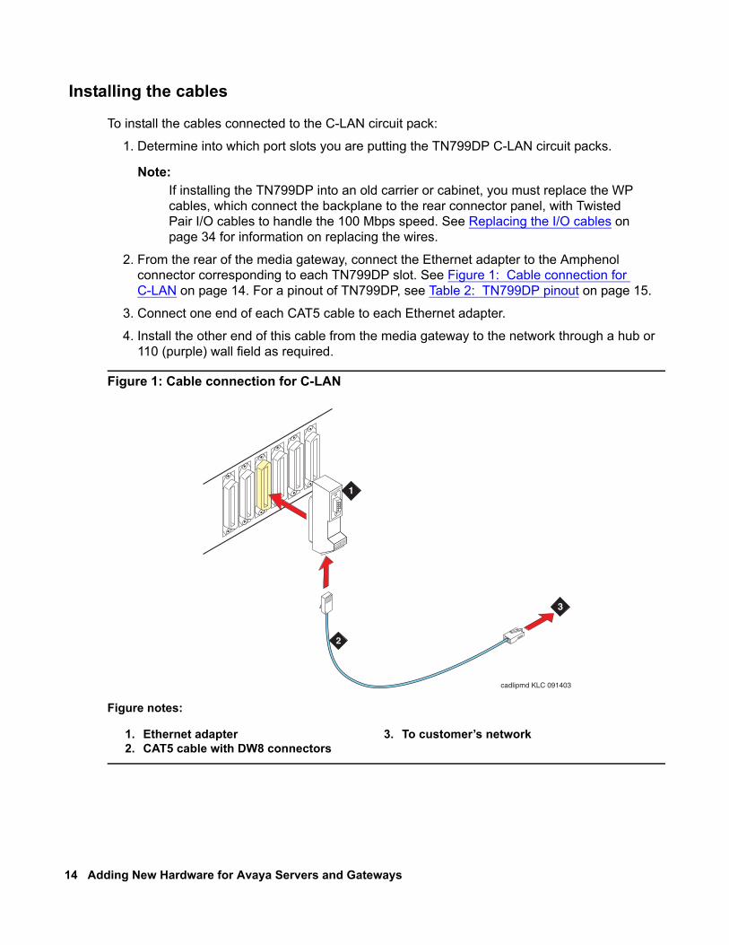
To install the cables connected to the C-LAN circuit pack:
1. Determine into which port slots you are putting the TN799DP C-LAN circuit packs.
Note:Note: If installing the TN799DP into an old carrier or cabinet, you must replace the WP
cables, which connect the backplane to the rear connector panel, with Twisted Pair I/O cables to handle the 100 Mbps speed. See Replacing the I/O cables on page 34 for information on replacing the wires.
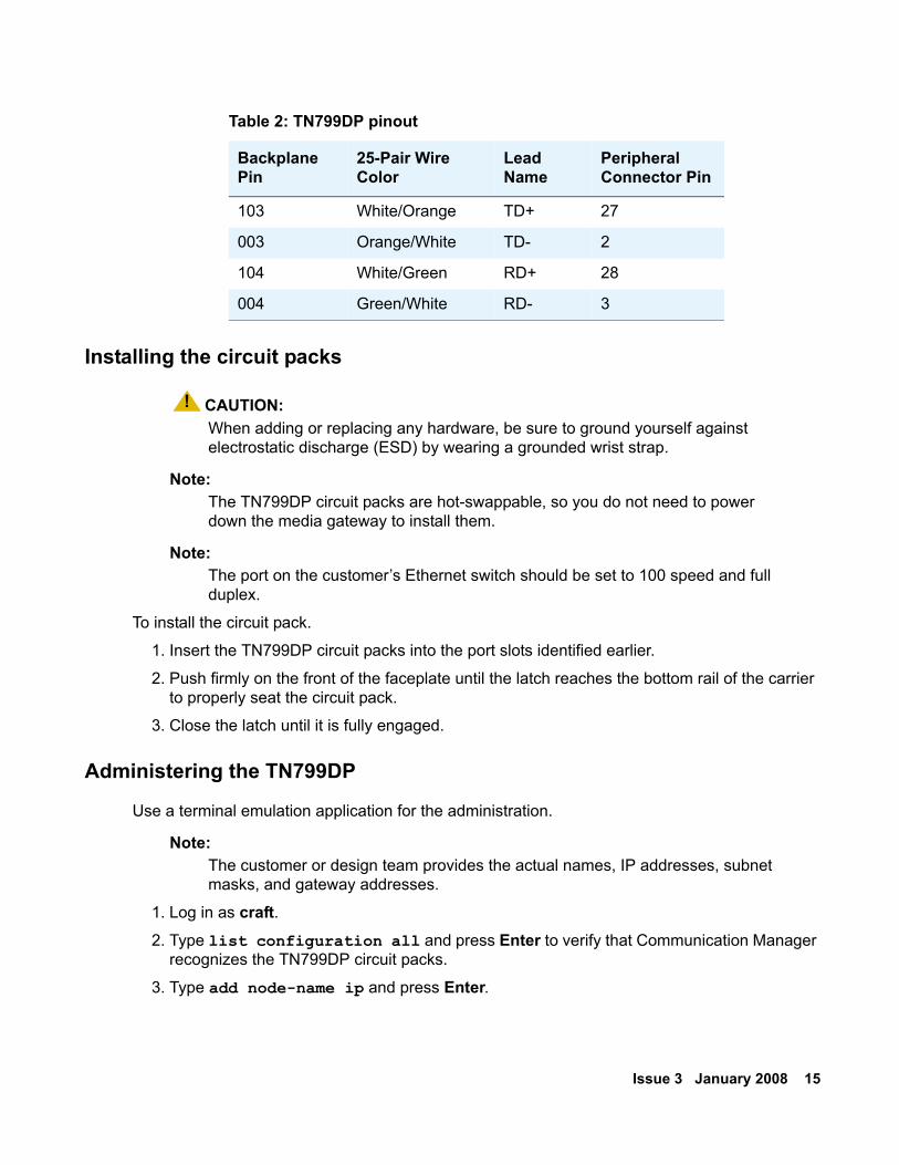
2. From the rear of the media gateway, connect the Ethernet adapter to the Amphenol connector corresponding to each TN799DP slot. See Figure 1: Cable connection for C-LAN on page 14. For a pinout of TN799DP, see Table 2: TN799DP pinout on page 15.
3. Connect one end of each CAT5 cable to each Ethernet adapter.
4. Install the other end of this cable from the media gateway to the network through a hub or 110 (purple) wall field as required.
Figure 1: Cable connection for C-LAN
Figure notes:
1. Ethernet adapter2. CAT5 cable with DW8 connectors
3. To customer’s network
cadlipmd KLC 091403
3
2
RS232 DEBUG
10/100bT ETHERNET
1
Issue 3 January 2008 15
Installing the circuit packs
! CAUTION:CAUTION: When adding or replacing any hardware, be sure to ground yourself against
electrostatic discharge (ESD) by wearing a grounded wrist strap.
Note:Note: The TN799DP circuit packs are hot-swappable, so you do not need to power
down the media gateway to install them.
Note:Note: The port on the customer’s Ethernet switch should be set to 100 speed and full
duplex.
To install the circuit pack.
1. Insert the TN799DP circuit packs into the port slots identified earlier.
2. Push firmly on the front of the faceplate until the latch reaches the bottom rail of the carrier to properly seat the circuit pack.
3. Close the latch until it is fully engaged.
Administering the TN799DP
Use a terminal emulation application for the administration.
Note:Note: The customer or design team provides the actual names, IP addresses, subnet
masks, and gateway addresses.
1. Log in as craft.2. Type list configuration all and press Enter to verify that Communication Manager
recognizes the TN799DP circuit packs.
3. Type add node-name ip and press Enter.
Table 2: TN799DP pinout
Backplane Pin
25-Pair Wire Color
Lead Name
Peripheral Connector Pin
103 White/Orange TD+ 27
003 Orange/White TD- 2
104 White/Green RD+ 28
004 Green/White RD- 3
16 Adding New Hardware for Avaya Servers and Gateways
4. Type in the node names and IP addresses for each TN799DP C-LAN circuit pack.
5. Type display circuit-pack cabinetnumber and press Enter, where cabinetnumber is the cabinet where the circuit packs reside to verify that the TN799DP shows up in the Code column.
6. Type add ip-interface UUCSS and press Enter, where UU is the cabinet, C is the carrier, and SS is the slot location of the TN799DP C-LAN circuit pack.
7. Type in the following information:
● The Type, Slot, IP Address, and Code/Suffix fields are populated automatically.
● In the Node Name field, type the same node name entered on the Node Name screen.
● In the Subnet Mask field, use the default setting unless you are given a different subnet mask.
● In the Gateway Address field, use the address you are given or leave blank.
● Set the Enable Ethernet Port field to y.
● Set the Net Region field to 1 unless you are given a different number.
● Set VLAN field to n.
8. Press Enter to save the information and effect the new settings.
9. Type add data-module next and press Enter.10. Set the Type field to ethernet.11. Set the Port field to correspond to the circuit pack location.
The port number (final two digits) is always 17 for the TN799DP circuit pack.
12. Set the Link field to an unassigned or next-available link number.
13. Set the Network uses 1’s for Broadcast Address? field according to the your network requirements.
14. Type a unique name in the Name field.
15. Press Enter to save your changes.
See the Administration for Network Connectivity for Avaya Communication Manager (555-233-504) for more information on these administration steps and for the steps to administer endpoints.
Testing the external connection to the LAN
To test the external IP connections, ping the gateway and a known computer connected to the network. If everything is configured correctly, you have a successful ping. If you cannot ping, verify the IP-address information and check the connectivity, including the cabling.

Issue 3 January 2008 17
To test the external IP connections, ping a computer on the same subnet, the gateway, and a computer beyond the gateway. If everything is configured correctly, the Result column on the Ping Results screen reads pass. If it reads abort, verify the IP-address information and check the connectivity, including the cabling.
1. Type ping ip-address ipaddress board UUCSS and press Enter, where ipaddress is the IP address of a computer on the same subnet and UUCSS is the cabinet, carrier, and slot location of the TN799DP C-LAN circuit pack that is used to send the ping.
2. If step 1 passes, type ping ip-address ipaddress board UUCSS and press Enter, where ipaddress is the IP address of the customer’s gateway and UUCSS is the cabinet, carrier, and slot location.
3. If step 2 passes, type ping ip-address ipaddress board UUCSS and press Enter, where ipaddress is the IP address of a computer beyond the gateway and UUCSS is the cabinet, carrier, and slot location.
The TN799DP C-LAN circuit pack is now installed in the media gateway and connected to the IP network.
TN2302AP IP Media Processor The TN2302AP IP Media Processor circuit pack provides an interface between a customer’s IP network and Avaya media gateways. This interface is used to transport voice and FAX between the media gateways and IP devices such as H.323 V2 compliant endpoints and other Avaya telephone systems. Each TN2302AP can support between 32 and 64 voice channels, depending on the codecs used.
Note:Note: The P board suffix designation means the circuit pack is firmware-downloadable.
Check the firmware vintage and upgrade availability for the TN2302AP circuit pack on the Avaya Support Web site: http://support.avaya.com.
The following sections describe the process:
● Checking your shipment on page 18
● Installing a TN2302AP IP Media Processor on page 18
● Installing the cables on page 19
● Installing the circuit packs on page 20
● Administering the IP Media Processor on page 21
● Testing the external connection to the LAN on page 22
● Verifying active call status on page 22
For further administration, see the Administration for Network Connectivity for Avaya Communication Manager (555-233-504).
18 Adding New Hardware for Avaya Servers and Gateways
Checking your shipment
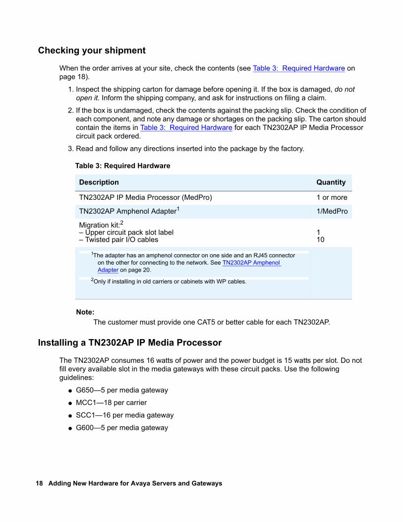
When the order arrives at your site, check the contents (see Table 3: Required Hardware on page 18).
1. Inspect the shipping carton for damage before opening it. If the box is damaged, do not open it. Inform the shipping company, and ask for instructions on filing a claim.
2. If the box is undamaged, check the contents against the packing slip. Check the condition of each component, and note any damage or shortages on the packing slip. The carton should contain the items in Table 3: Required Hardware for each TN2302AP IP Media Processor circuit pack ordered.
3. Read and follow any directions inserted into the package by the factory.
Note:Note: The customer must provide one CAT5 or better cable for each TN2302AP.
Installing a TN2302AP IP Media Processor
The TN2302AP consumes 16 watts of power and the power budget is 15 watts per slot. Do not fill every available slot in the media gateways with these circuit packs. Use the following guidelines:
● G650—5 per media gateway
● MCC1—18 per carrier
● SCC1—16 per media gateway
● G600—5 per media gateway
Table 3: Required Hardware
Description Quantity
TN2302AP IP Media Processor (MedPro) 1 or more
TN2302AP Amphenol Adapter1 1/MedPro
Migration kit:2 – Upper circuit pack slot label– Twisted pair I/O cables
110
1The adapter has an amphenol connector on one side and an RJ45 connector on the other for connecting to the network. See TN2302AP Amphenol Adapter on page 20.
2Only if installing in old carriers or cabinets with WP cables.
Issue 3 January 2008 19
Have the following equipment on site before your shipment arrives:
● An unoccupied port slot in the media gateway for each TN2302AP IP Media Processor
● A 10 BaseT or 10/100 BaseT Ethernet connection into your local area network (LAN)
● One or more valid, unused IP addresses on the network that can be assigned to the IP Media Processor server. You also need the subnet mask and default gateway.
Note:Note: Get this information from the project manager or the customer’s network
administrator.
In addition to the TN2302AP IP Media Processor, you also must install and administer a TN799CP C-LAN circuit pack. For C-LAN installation and administration, see TN799DP Control LAN on page 12.
Installing the cables
To install the cable for the IP Media Processor circuit pack:
1. Determine into which port slots you are putting the TN2302AP IP Media Processor circuit packs.
From the rear of the media gateway:
Note:Note: If installing the TN2302AP into an old carrier or cabinet, you must replace the WP
cables, which connect the backplane to the rear connector panel, with Twisted Pair I/O cables to handle the 100 Mbps speed. See Replacing the I/O cables on page 34 for information on replacing the wires.
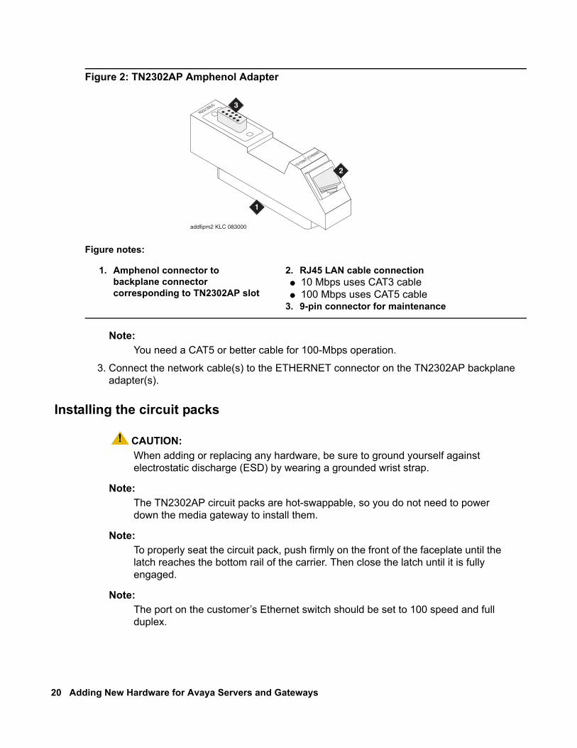
2. Connect the amphenol connector on the adapter to the Amphenol connector corresponding to each TN2302AP slot. See Figure 2: TN2302AP Amphenol Adapter on page 20.
20 Adding New Hardware for Avaya Servers and Gateways
Figure 2: TN2302AP Amphenol Adapter
Note:Note: You need a CAT5 or better cable for 100-Mbps operation.
3. Connect the network cable(s) to the ETHERNET connector on the TN2302AP backplane adapter(s).
Installing the circuit packs
! CAUTION:CAUTION: When adding or replacing any hardware, be sure to ground yourself against
electrostatic discharge (ESD) by wearing a grounded wrist strap.
Note:Note: The TN2302AP circuit packs are hot-swappable, so you do not need to power
down the media gateway to install them.
Note:Note: To properly seat the circuit pack, push firmly on the front of the faceplate until the
latch reaches the bottom rail of the carrier. Then close the latch until it is fully engaged.
Note:Note: The port on the customer’s Ethernet switch should be set to 100 speed and full
duplex.
Figure notes:
1. Amphenol connector to backplane connector corresponding to TN2302AP slot
2. RJ45 LAN cable connection● 10 Mbps uses CAT3 cable● 100 Mbps uses CAT5 cable
3. 9-pin connector for maintenance
addfipm2 KLC 083000
1
2
3
Issue 3 January 2008 21
To install the circuit pack.
1. Insert the TN2302AP IP Media Processor into the port slot you reserved for it and seat it properly.
When you plug in the TN2302AP IP Media Processor, the circuit pack starts to boot. The RED LED stays on until an IP address is assigned to the circuit pack.
Administering the IP Media Processor
Use a terminal emulation application for the administration.
1. Log in as craft.
2. Type list configuration all and press Enter to verify that Communication Manager recognizes the TN2302AP circuit packs.
3. Type add node-names and press Enter.4. On page 2, type in the node names and IP addresses for the TN2302AP.
5. Type display circuit-pack and press Enter. Verify that the TN2302AP shows up in the Code column.
6. Type add ip-interface UUCSS and press Enter, where UUCSS is the cabinet, carrier, and slot location.
7. Type in the following information:
● The Type, Slot, IP Address, and Code/Suffix fields are populated automatically.
● In the Node Name field, type the same node name entered on the Node Name screen.
● In the Subnet Mask field, use the default setting unless you are given a different subnet mask.
● In the Gateway Address field, use the address you are given or leave blank.
● Set the Enable Ethernet Port field to y.
● Set the Net Region field to 1 unless you are given a different number.
● Set VLAN to n.
8. Press Enter to save the information and effect the new settings.
22 Adding New Hardware for Avaya Servers and Gateways
Testing the external connection to the LAN
To test the external IP connections, ping a computer on the same subnet, the gateway, and a computer beyond the gateway. If everything is configured correctly, the Result column on the Ping Results screen reads pass. If it reads abort, verify the IP-address information and check the connectivity, including the cabling.
1. Type ping ip-address ipaddress board UUCSS and press Enter, where ipaddress is the IP address of a computer on the same subnet and UUCSS is the cabinet, carrier, and slot location of the TN2302AP IP Media Processor.
2. If step 1 passes, type ping ip-address ipaddress board UUCSS and press Enter, where ipaddress is the IP address of the customer’s gateway and UUCSS is the cabinet, carrier, and slot location.
3. If step 2 passes, type ping ip-address ipaddress board UUCSS and press Enter, where ipaddress is the IP address of a computer beyond the gateway and UUCSS is the cabinet, carrier, and slot location.
The TN2302AP IP Media Processor circuit pack is now installed in the media gateway and connected to the IP network.
Verifying active call status
To verify that calls are being processed:
1. Type status media processor board UUCSS.
2. Look at the LINKS and DSP CHANNEL STATUS categories to determine whether calls are being processed.
See the Administration for Network Connectivity for Avaya Communication Manager (555-233-504) for more information on these administration steps and for the steps to administer endpoints.
TN2501AP Voice announcements over LAN (VAL) The TN2501AP voice announcements over LAN (VAL) circuit pack is an integrated announcement circuit pack that uses *.wav files for announcements and plays them over the TDM bus. It can store up to 1 hour of announcement storage capacity.
Issue 3 January 2008 23
Installing a TN2501AP VAL
Note:Note: The P board suffix designation means the circuit pack is firmware-downloadable.
Note:Note: To install a TN2501AP, make sure that the system is enabled for TN2501AP
(VAL) circuit packs. If the Maximum VAL boards field on the System Parameters Customer Options screen is set to 0, then you need to obtain and install a new license file before you can install the card.
Check the firmware vintage and upgrade availability for the TN2501AP circuit pack on the Avaya Support Web site: http://support.avaya.com.
Installing the pack includes:
● Verifying the required hardware on page 23
● Installing the circuit packs on page 24
● Administering the TN2501AP on page 25
Verifying the required hardwareMake sure that you have the required hardware:
● TN2501AP VAL circuit pack (108772583).
● 10/100BaseT backplane adapter (848525887—same one used for the IP Media Processor). See Figure 3: Backplane adapter on page 24.
● Tight-twisted I/O cable kit (700234032) only if installing in old carriers or cabinets with WP cables.
● LAN cable with RJ45 connectors (customer supplied).
24 Adding New Hardware for Avaya Servers and Gateways
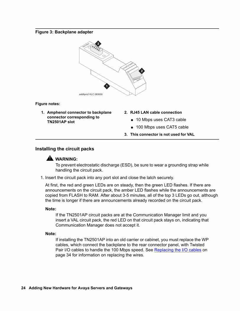
Figure 3: Backplane adapter
Installing the circuit packs
! WARNING:WARNING: To prevent electrostatic discharge (ESD), be sure to wear a grounding strap while
handling the circuit pack.
1. Insert the circuit pack into any port slot and close the latch securely.
At first, the red and green LEDs are on steady, then the green LED flashes. If there are announcements on the circuit pack, the amber LED flashes while the announcements are copied from FLASH to RAM. After about 3-5 minutes, all of the top 3 LEDs go out, although the time is longer if there are announcements already recorded on the circuit pack.
Note:Note: If the TN2501AP circuit packs are at the Communication Manager limit and you
insert a VAL circuit pack, the red LED on that circuit pack stays on, indicating that Communication Manager does not accept it.
Note:Note: If installing the TN2501AP into an old carrier or cabinet, you must replace the WP
cables, which connect the backplane to the rear connector panel, with Twisted Pair I/O cables to handle the 100 Mbps speed. See Replacing the I/O cables on page 34 for information on replacing the wires.
Figure notes:
1. Amphenol connector to backplane connector corresponding to TN2501AP slot
2. RJ45 LAN cable connection
● 10 Mbps uses CAT3 cable
● 100 Mbps uses CAT5 cable
3. This connector is not used for VAL
addfipm2 KLC 083000
1
2
3
Issue 3 January 2008 25
2. Connect the backplane adapter to the Amphenol connector on the back of the media gateway corresponding to the TN2501AP circuit pack slot.
3. Connect the LAN CAT5 cable to the RJ45 connector on the backplane adapter.
Administering the TN2501APAfter you have installed the hardware, to support an FTP session you must administer and test the installation.
Use a terminal emulation application or Avaya Site Administration for this administration.
1. Type list configuration board board-location and press Enter.The System Configuration report appears. Use this report to ensure that the Communication Manager recognizes the TN2501AP circuit pack after it is latched in the carrier slot.
2. Verify the following field values:
● Board Type shows VAL-ANNOUNCEMENT● Code is TN2501AP
3. Type add node-names ip and press Enter.4. In the Name field, type a unique name.
This name is recognized only within the Communication Manager and does not need to match the node name on your network.
5. Type the IP Address.
Get this information from the project manager or the customer’s network administrator.
6. Press Enter to save the changes.
7. Type add ip-interface UUCSS and press Enter, where UUCSS is the cabinet, carrier, and slot location.
8. Type in the following information:
● The Type, Slot, IP Address, and Code/Suffix fields are populated automatically.
● In the Node Name field, type the same node name entered on the Node Name screen.
● In the Subnet Mask field, use the default setting unless you are given a different subnet mask.
● In the Gateway Address field, use the address you are given or leave blank.
● Set the Enable Ethernet Port field to y.
● Set the Net Region field to 1 unless you are given a different number.
● Set VLAN to n.
9. Press Enter to save the changes.
10. Type add data-module extension and press Enter.
26 Adding New Hardware for Avaya Servers and Gateways
11. Set the Type field to ethernet.12. Set the Port field to correspond to the circuit pack location.
The port number (final two digits) is always 33 for the TN2501AP circuit pack.
13. Set the Link field to an unassigned or next-available link number.
14. Set the Network uses 1’s for Broadcast Address? field according to the your network requirements.
15. In the Name field, type a unique name.
16. Press Enter to save your changes.
17. Type add ip-route and press Enter.18. Administer IP routes to the TN2501AP circuit pack.
19. Press Enter to effect the changes.
Testing the external connection to the LAN
To test the connection to the LAN.
1. Click Start > Run to open the Run dialog box.
2. Type command and press Enter to open an MS-DOS command window.
3. Type ping ipaddress, where ipaddress is a known computer on the network and press Enter to verify connectivity.
4. Type status link to test the new IP connections that you have administered.
TN2602AP IP Media Resource 320The TN2602AP IP Media Resource 320 provides high-capacity voice over Internet protocol (VoIP) audio access to the switch for local stations and outside trunks. The IP Media Resource 320 provides audio processing for the following types of calls:
● TDM-to-IP and IP-to-TDM — for example, a call from a 4602 IP telephone to a 6402 DCP telephone
● IP-to-IP — for example, a non-shuffled conference callThe TN2602AP IP Media Resource 320 circuit pack has 320 voice channels. Only two TN2602AP circuit packs are allowed per port network.
Note:Note: The TN2602AP IP Media Resource 320 is not supported in CMC1 and G600
Media Gateways.
Issue 3 January 2008 27
Up to two TN2602AP circuit packs may be installed in a single port network for load balancing. The TN2602AP circuit pack is also compatible with and can share load balancing with the TN2302 and TN802B IP Media Processor circuit packs. Actual capacity may be affected by a variety of factors, including the codec used for a call and fax support.
Note:Note: When two TN2602AP circuit packs, each with 320 voice channels, are used for
load balancing within a port network, the total number of voice channels available is 484, because 484 is the maximum number of time slots available for a port network.
Two TN2602AP circuit packs may be installed in a single port network (PN) for bearer duplication. In this configuration, one TN2602AP is an active IP media processor and one is a standby IP media processor. If the active media processor, or connections to it, fail, active connections failover to the standby media processor and remain active. This duplication prevents active calls in progress from being dropped in case of failure. The interchange between duplicated circuit packs affects only the PN in which the circuit packs reside.
Note:Note: The 4606, 4612, and 4624 telephones do not support the bearer duplication
feature of the TN2602AP circuit pack. If these telephones are used while an interchange from active to standby media processor is in process, calls may be dropped.
The Communication Manager license file must have entries for each circuit pack, with the entries having identical voice channels enabled. In addition, both circuit packs must have the latest firmware that supports bearer duplication.
Duplicated TN2602AP circuit packs must be in the same subnet. In addition, the Ethernet switch or switches that the circuit packs connect to must also be in the same subnet. This shared subnet allows the Ethernet switches to use signals from the TN2602AP firmware to identify the MAC address of the active circuit pack. This identification process provides a consistent virtual interface for calls.
A single port network can have up to two TN2602AP circuit packs only. As result, the port network can have either two duplicated TN2602AP circuit packs or two load balancing TN2602AP circuit packs, but not both a duplicated pair and a load-balancing pair. However, in a Communication Manager configuration, some port networks can have a duplicated pair of TN2602AP circuit packs and other port networks can have a load-balancing pair of TN2602AP circuit packs. Some port networks can also have single or no TN2602AP circuit packs.
Note:Note: If a pair of TN2602AP circuit packs previously used for load balancing are
re-administered to be used for bearer duplication, only the voice channels of whichever circuit pack is active can be used. For example, if you have two TN2602 AP circuit packs in a load balancing configuration, each with 320 voice channels, and you re-administer the circuit packs to be in bearer duplication mode, you will have 320 (rather than 484) channels available.
28 Adding New Hardware for Avaya Servers and Gateways
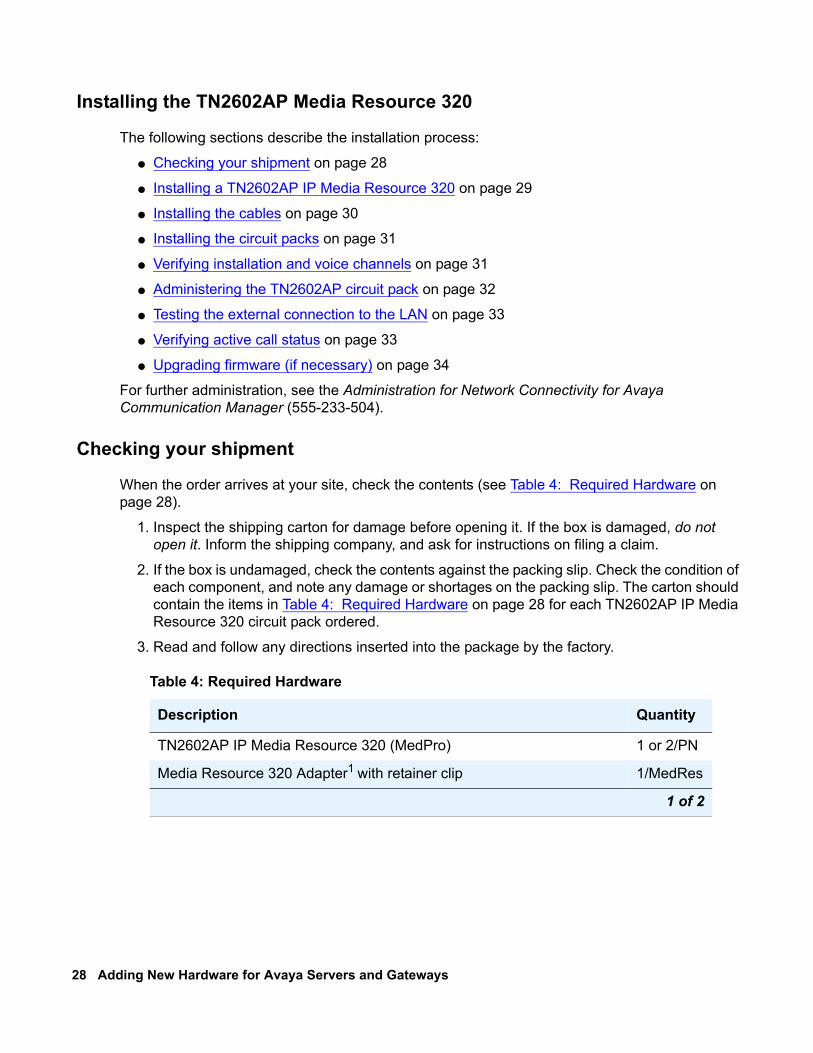
Installing the TN2602AP Media Resource 320
The following sections describe the installation process:
● Checking your shipment on page 28
● Installing a TN2602AP IP Media Resource 320 on page 29
● Installing the cables on page 30
● Installing the circuit packs on page 31
● Verifying installation and voice channels on page 31
● Administering the TN2602AP circuit pack on page 32
● Testing the external connection to the LAN on page 33
● Verifying active call status on page 33
● Upgrading firmware (if necessary) on page 34
For further administration, see the Administration for Network Connectivity for Avaya Communication Manager (555-233-504).
Checking your shipment
When the order arrives at your site, check the contents (see Table 4: Required Hardware on page 28).
1. Inspect the shipping carton for damage before opening it. If the box is damaged, do not open it. Inform the shipping company, and ask for instructions on filing a claim.
2. If the box is undamaged, check the contents against the packing slip. Check the condition of each component, and note any damage or shortages on the packing slip. The carton should contain the items in Table 4: Required Hardware on page 28 for each TN2602AP IP Media Resource 320 circuit pack ordered.
3. Read and follow any directions inserted into the package by the factory.
Table 4: Required Hardware
Description Quantity
TN2602AP IP Media Resource 320 (MedPro) 1 or 2/PN
Media Resource 320 Adapter1 with retainer clip 1/MedRes
1 of 2
Issue 3 January 2008 29
Note:Note: The customer must provide one CAT5 or better cable for each TN2602AP.
Installing a TN2602AP IP Media Resource 320
Note:Note: Only two TN2602AP circuit packs are allowed per port network.
Have the following equipment and information on site before your shipment arrives:
Note:Note: If used in place of an Expansion Interface circuit pack in a mixed port network
configuration, we recommend that the TN2602AP circuit pack be installed in the A01 slot.
● One or two unoccupied port slots in the media gateway for the TN2602AP circuit pack(s).
● One or two 10/100 BaseT Ethernet connections into the customer’s local area network (LAN)
● One or two valid, unused IP addresses on the network that can be assigned to the IP Media Resource 320 server. You also need the subnet mask, which should be the same for each of the TN2602AP circuit packs installed on the same port network. You may need the default gateway if the circuit pack handles off-subnet calls.
Note:Note: Get this information from the project manager or the customer’s network
administrator.
Migration kit (PEC code 63275):2 – Upper circuit pack slot label– Twisted pair I/O cables
110
1The adapter has an amphenol connector on one side, an RJ45 connector and 2 Ethernet ports on the other for connecting to the network. See Media Resource 320 Adapter on page 30.
2Only if installing in old carriers or cabinets with WP cables.
Table 4: Required Hardware (continued)
Description Quantity
2 of 2
30 Adding New Hardware for Avaya Servers and Gateways
Installing the cables
To install the cable for the IP Media Resource 320 circuit pack:
Note:Note: If used in place of an Expansion Interface circuit pack in a mixed port network
configuration, we recommend that the TN2602AP circuit pack be installed in the A01 slot.
1. Determine into which port slot(s) you are putting the TN2602AP circuit pack(s).
From the rear of the media gateway:
Note:Note: If installing the TN2602AP into an old carrier or cabinet, you must replace the WP
cables, which connect the backplane to the rear connector panel, with Twisted Pair I/O cables to handle the 100 Mbps speed. See Replacing the WP cables on page 40 for information on replacing the wires.
2. Connect the amphenol connector on the adapter to the Amphenol connector corresponding to each TN2602AP slot. See Figure 4: Media Resource 320 Adapter.
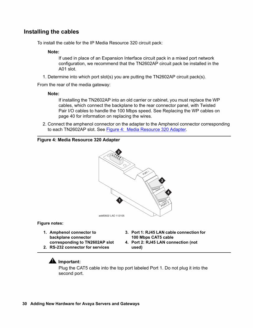
Figure 4: Media Resource 320 Adapter
! Important:Important: Plug the CAT5 cable into the top port labeled Port 1. Do not plug it into the
second port.
Figure notes:
1. Amphenol connector to backplane connector corresponding to TN2602AP slot
2. RS-232 connector for services
3. Port 1: RJ45 LAN cable connection for 100 Mbps CAT5 cable
4. Port 2: RJ45 LAN connection (not used)
addf2602 LAO 112105
PORT 1
PORT 21
2
3
4
Issue 3 January 2008 31
3. Connect the network cable(s) to the Port 1 ETHERNET connector on the Media Resource 320 adapter(s) on the backplane.
4. Snap the retainer clip(s) over the adapter(s) to hold them in place.
Installing the circuit packs
! CAUTION:CAUTION: When adding or replacing any hardware, be sure to ground yourself against
electrostatic discharge (ESD) by wearing a grounded wrist strap.
Note:Note: The TN2602AP circuit packs are hot-swappable, so you do not need to power
down the media gateway to install them.
Note:Note: To properly seat the circuit pack, push firmly on the front of the faceplate until the
latch reaches the bottom rail of the carrier. Then close the latch until it is fully engaged.
To install the circuit pack.
1. Insert the TN2602AP circuit pack into the port slot you reserved for it and seat it properly.
When you plug in the TN2602AP circuit pack, it starts to boot. The RED LED stays on until the onboard firmware is operational.
Verifying installation and voice channels
To verify the installation:
1. Type list configuration board UUCSS and press Enter, where UUCSS is the cabinet, carrier, and slot location of the TN2602AP.
2. Verify that TN2602AP shows in the slot location.
3. Look under the Vintage column and note the firmware version. If the firmware version is lower than the one on the Avaya Support Web site, you must upgrade the firmware on the circuit pack. See the Firmware Download Procedure document, which is posted on the Avaya Download Web site.
4. Type display system-parameters customer-options and press Enter.5. Find the Maximum TN2602 VoIP Channels: field. Look at the Used column next to the field
to see the maximum number of voice channels available.
32 Adding New Hardware for Avaya Servers and Gateways
Administering the TN2602AP circuit pack
To administer the circuit pack:
1. Type change node-names ip and press Enter.2. Type in the node names and IP addresses for the TN2602AP.
3. Type display circuit-packs and press Enter. Verify that the TN2602AP shows up in the Code column.
4. Type add ip-interface UUCSS and press Enter, where UUCSS is the cabinet, carrier, and slot location.
5. Type in the following information:
● If administering two circuit packs as duplicated, in the Critical Reliable Bearer? field, type y.
Note:Note: If Critical Reliable Bearer? is yes, a second column of information displays. Fill
in information for both circuit packs.
● The Type, Slot, IP Address, and Code/Suffix fields are populated automatically.
● In the Node Name field, type the same node name entered on the Node Name screen.
● In the Subnet Mask field, enter the subnet mask determined by the LAN administrator. This setting also applies to the second TN2602AP circuit pack when Critical Reliable Bearer is y.
● In the Gateway Address field, use the address determined by the LAN administrator. This setting also applies to the second TN2602AP circuit pack when Critical Reliable Bearer is y.
● Set the Enable Ethernet Port field to y.
● Set the Net Region field to 1 or another number determined by the LAN administrator. This setting also applies to the second TN2602AP circuit pack when Critical Reliable Bearer is y.
● Set VLAN to n.
● Set the VOIP Channel field to 320.
● Set the Shared Virtual Address field to the virtual IP address shared by the two TN2602AP circuit packs.
● Set the Virtual MAC Table field to a number from 1 to 4. Normally, you can enter 1. However, you might choose a different table number if all of the following conditions exist:
- A port network under the control of a different Communication Manager main server has duplicated TN2602AP circuit packs.
- That port network controlled by a different main server has the same number as the port network in which you are administering the TN2602AP circuit packs.
Issue 3 January 2008 33
- The port network or its main server connects to the same Ethernet switch as the port network in which you are administering the TN2602AP circuit packs.
Selecting a different Virtual MAC Table from that chosen for a port network that has the previously-listed conditions helps prevent the possibility that two TN2602AP circuit packs within the customer’s network will have the same virtual MAC address.
● The Virtual MAC Address field is populated automatically with a MAC address from the Virtual MAC Table you select.
● Set Ethernet Options to match the customers network. The recommended settings are
- Auto: y (default)
If you enter n, also complete the following fields. The recommended values are displayed.
- Speed: 100 Mbps- Duplex: Full
6. Press Enter to save the information and effect the new settings.
Testing the external connection to the LAN
To test the external IP connections, ping a computer on the same subnet, the gateway, and a computer beyond the gateway. If everything is configured correctly, the Result column on the Ping Results screen reads pass. If it reads abort, verify the IP-address information and check the connectivity, including the cabling.
1. Type ping ip-address ipaddress board UUCSS and press Enter, where ipaddress is the IP address of the TN2602AP IP Media Resource 320 and UUCSS is the cabinet, carrier, and slot location of a C-LAN circuit pack or another media processor circuit pack within the subnet.
2. If step 1 passes, type ping ip-address ipaddress board UUCSS and press Enter, where ipaddress is the IP address of an endpoint on the customer’s gateway and UUCSS is the cabinet, carrier, and slot location of the TN2602AP circuit pack you are testing.
3. If step 2 passes, type ping ip-address ipaddress board UUCSS and press Enter, where ipaddress is the IP address of an endpoint beyond the gateway and UUCSS is the cabinet, carrier, and slot location of the TN2602AP circuit pack you are testing.
Verifying active call status
To verify that calls are being processed:
1. Type status media processor board UUCSS, where UUCSS is the board location.
2. Look at the LINKS and DSP CHANNEL STATUS categories to determine whether calls are being processed.
34 Adding New Hardware for Avaya Servers and Gateways
Testing the circuit pack
Test the TN2602AP circuit pack with the command test board UUCSS. For more information, see the Maintenance Commands for Avaya Communication Manager R3.1 Media Gateways and Servers, 03-300431.
Upgrading firmware (if necessary)
If you determined that you must upgrade the firmware, do so now. More information on firmware downloads, and instructions for downloading, are available at:
http://www.avaya.com/support/
Click Download Center!.
Firmware upgradesFirmware is upgraded the same way as the TN799DP C-LAN and TN2501AP VAL circuit packs. Resetting the circuit pack as part of the process affects the bearer traffic.
Replacing the I/O cables
Note:Note: You only need to replace the I/O cables for the TN2602AP circuit packs you are
installing.
On older MCC1, SCC1, and G600 media gateways (cabinets) you must replace the existing I/O cables (WP-90753, LI) with twisted pair I/O cables. These I/O cables connect the backplane to the rear connector panel.
The existing I/O cables have straight, not twisted, wires. These cables can be mostly white with two red or multicolored. If the cables have multicolored, tightly twisted wires, no replacement is necessary.
! CAUTION:CAUTION: Turn off power to the carrier or the media gateway before you replace the cables.
! CAUTION:CAUTION: When you add or replace any hardware and associated cables and adapters,
ground yourself against electrostatic discharge (ESD). Always wear a grounded wrist strap.
Issue 3 January 2008 35
To replace the existing I/O cables:
1. Perform one of the following actions:
● If the configuration includes an MCC1 or an SCC1 Media Gateway, continue with step 2.
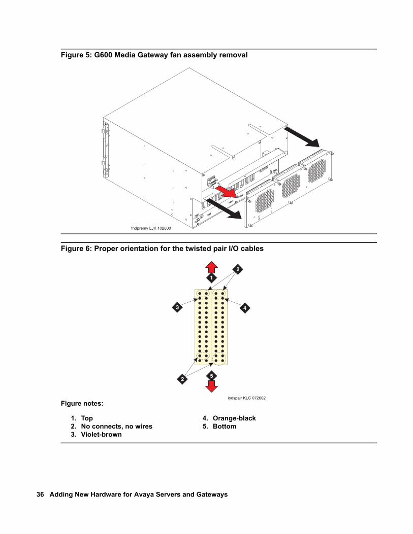
● If the configuration includes a G600 Media Gateway, you must remove the fan assembly to access the cables. Loosen the thumb screws on the fan assembly and pull it straight out (G600 Media Gateway fan assembly removal on page 36). Leave the fan assembly off until you install all the wires.
2. Note the orientation of the existing 10 cables. The existing I/O cables can be white and red or multicolored. These cables are not twisted.
3. Remove the I/O cables that you want to replace from the backplane and the connector panel slots.
4. Install the twisted pair I/O cables onto the backplane in the place of the cables you just removed. Use the correct orientation (Proper orientation for the twisted pair I/O cables on page 36). Observe the white outline that is printed on the backplane for the location of each connector.
5. View the cables from the “wiring” side of the twin connectors. That is, view the cables while you plug the cables into the backplane. Connectors oriented correctly for plug-in look like the cables in Proper orientation for the twisted pair I/O cables on page 36.
The circled pin locations are “No-Connects.” At the top there is an orange-black pair on the right and a violet-brown pair on the left. Do not install wires in these locations.
If you are replacing I/O cables for all slot positions, plug all cables into the backplane before you match the “D” connector on each cable to the carrier frame.
You must install the 50-position metal shell “D” connectors into the carrier frame. Make sure that the longer side of the “D” connector (pins 1 to 25) is toward the right when you view the pins from the rear of the media gateway.
6. Apply the 10/100 mbps label to the front of the carrier slot. Apply the label over the slot label that corresponds to the slot where you installed the twisted pair I/O cable.
7. For the G600 Media Gateway, replace the fan unit if you are not adding any media gateways. If you are adding more media gateways to the rack, leave the fan units off until you install all the TDM cables.
36 Adding New Hardware for Avaya Servers and Gateways
Figure 5: G600 Media Gateway fan assembly removal
Figure 6: Proper orientation for the twisted pair I/O cables
Figure notes:
1. Top2. No connects, no wires3. Violet-brown
4. Orange-black5. Bottom
fndpremv LJK 102600
1
3 4
5
2
2
iodspair KLC 072602
Issue 3 January 2008 37
Chapter 3: Adding hard drives and power supplies to S8730 Servers
This chapter gives procedures for installing an additional hard drive and an additional power supply to an S8730 Server.
Use these procedures if the customer has one or both of the following optional configurations:
● RAID level 1 configuration with disk mirroring.
One or more hard drives may be added in order to take advantage of the RAID level 1 feature, which provides disk mirroring. In this configuration, a customer’s data is mirrored on two or more disks, thus increasing the availability of the system. Each of the disks is independent of each other and contains a complete copy of the data. No administration is necessary to activate the RAID feature. Once an additional hard drive is installed, Communication Manager recognizes the additional hard drive and automatically activates RAID. Use the procedure Installing an additional hard drive on page 37.
● Dual power supply configuration.
An extra power supply may be added to S8730 Servers to increase availability. Use the procedure Installing an additional power supply on page 39.
Installing an additional hard driveHave the following equipment on site:
● S8730 HARD DISK 72 GB SAS HDD (RAID DISK) (Material code 7004445794)
● Electrostatic wrist ground strap and mat
Note:Note: You do not need to power down the server to add the extra hard drive.
! CAUTION:CAUTION: Wear an antistatic wrist ground strap whenever handling the hard drive. Connect
the strap to an approved ground, such as an unpainted metal surface. Also, place the hard drive on an antistatic mat that is similarly grounded. Do not place the drive on a bare surface.
To install an additional hard drive:
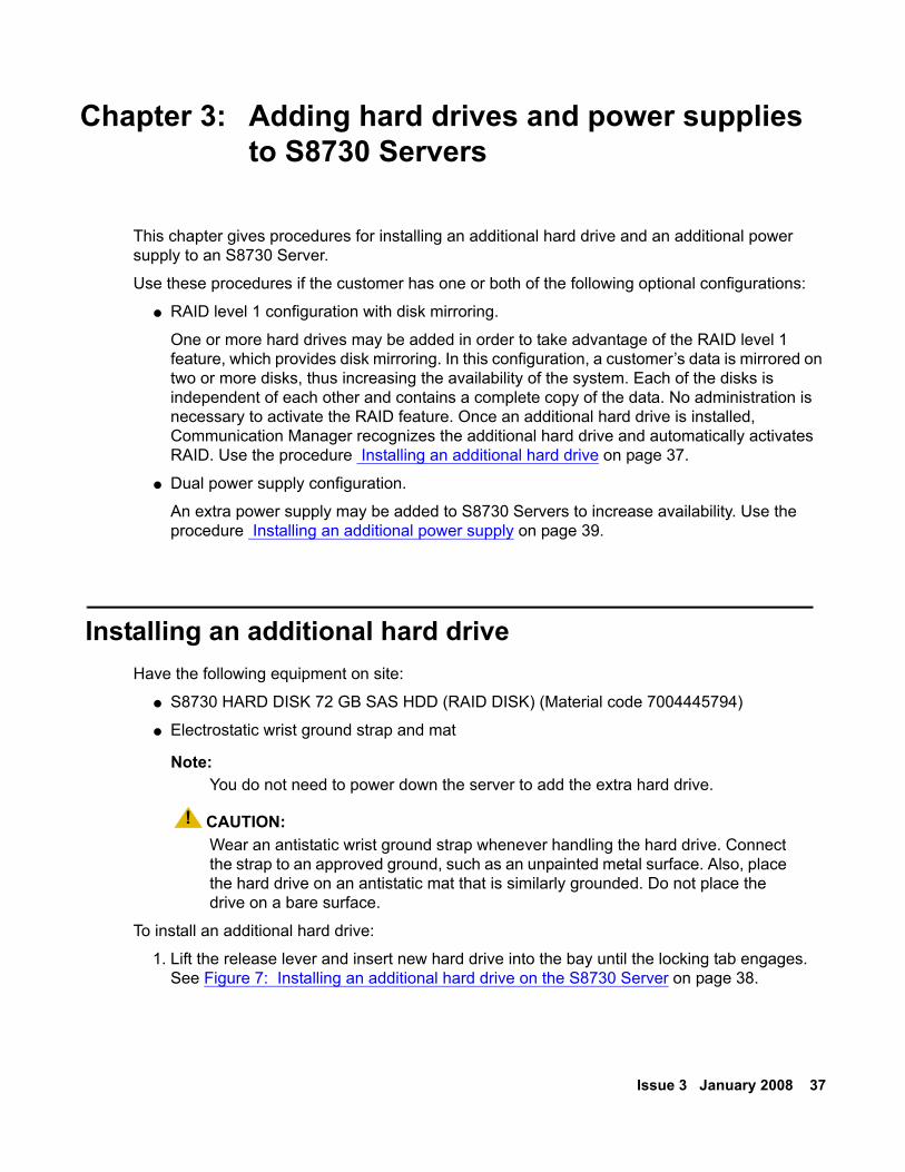
1. Lift the release lever and insert new hard drive into the bay until the locking tab engages. See Figure 7: Installing an additional hard drive on the S8730 Server on page 38.
38 Adding New Hardware for Avaya Servers and Gateways
2. Close the release lever to securely seat the hard drive in the bay. See Figure 7: Installing an additional hard drive on the S8730 Server on page 38.
Note:Note: After installing the extra drive, you do not have to remaster it with Communication
Manager software, apply service packs, or restore translations. The RAID software builds the drive automatically.
3. Make sure the new hard drive begins to be rebuilt. The raid_status command can be used to help with this. To follow the progress of the rebuild process, repeat the raid_status command several times. When the rebuilding is complete, a message will be displayed, ending with OK.
Figure 7: Installing an additional hard drive on the S8730 Server
hw873dr2 LAO 091807
UID
12
FANS
INTERLOCKOVERTEMPI-PPM
DIMMS
DIMMS
POWERSUPPLY POWER
SUPPLY
PCIRISERCAGE
PPMPROC
PROC
2
3
1
4
Issue 3 January 2008 39
Installing an additional power supplyHave the following equipment on site:
● Power supply for S8730 Server (Material Code 700445802)
Note:Note: You do not have to power down the server to install an additional power supply.
! WARNING:WARNING: To reduce the risk of electric shock or damage to the equipment, do not connect
the power cord to the power supply until you install the power supply.
To install an additional power supply:
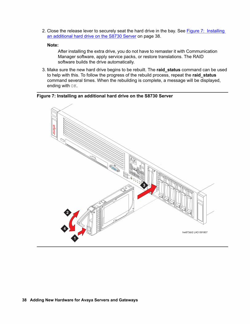
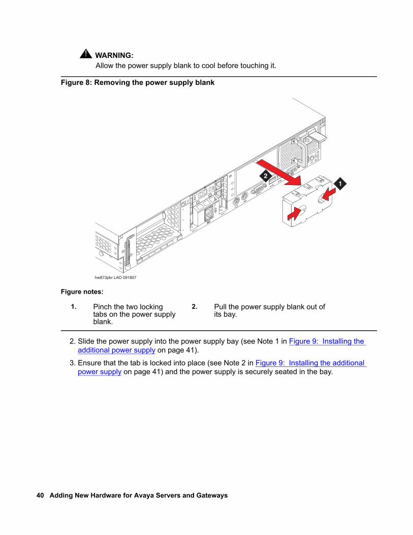
1. On the S8730 rear panel, remove the power supply blank. See Figure 8: Removing the power supply blank on page 40.
40 Adding New Hardware for Avaya Servers and Gateways
! WARNING:WARNING: Allow the power supply blank to cool before touching it.
Figure 8: Removing the power supply blank
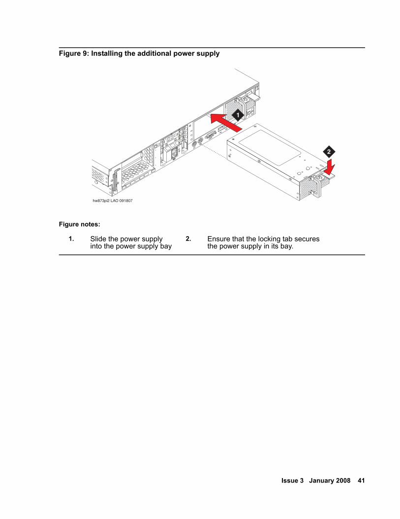
2. Slide the power supply into the power supply bay (see Note 1 in Figure 9: Installing the additional power supply on page 41).
3. Ensure that the tab is locked into place (see Note 2 in Figure 9: Installing the additional power supply on page 41) and the power supply is securely seated in the bay.
Figure notes:
1. Pinch the two locking tabs on the power supply blank.
2. Pull the power supply blank out of its bay.
1
2
UID
ILO 2
PCIe 1
PCIe 23
4
5
hw873pbr LAO 091807
12
Issue 3 January 2008 41
Figure 9: Installing the additional power supply
Figure notes:
1. Slide the power supply into the power supply bay
2. Ensure that the locking tab secures the power supply in its bay.
1
2
UID
ILO 2
PCIe 1
PCIe 23
4
5
hw873pi2 LAO 091807
2
1

42 Adding New Hardware for Avaya Servers and Gateways
Issue 3 January 2008 43
Chapter 4: Trunks and lines
This chapter provides procedures for adding analog and digital trunks and lines to an existing media gateway. These procedures are examples only. Actual wiring procedures might vary at each site.
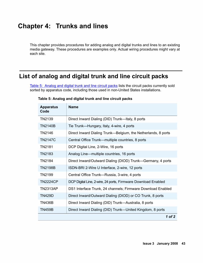
List of analog and digital trunk and line circuit packs Table 5: Analog and digital trunk and line circuit packs lists the circuit packs currently sold sorted by apparatus code, including those used in non-United States installations.
Table 5: Analog and digital trunk and line circuit packs
Apparatus Code
Name
TN2139 Direct Inward Dialing (DID) Trunk—Italy, 8 ports
TN2140B Tie Trunk—Hungary, Italy, 4-wire, 4 ports
TN2146 Direct Inward Dialing Trunk—Belgium, the Netherlands, 8 ports
TN2147C Central Office Trunk—multiple countries, 8 ports
TN2181 DCP Digital Line, 2-Wire, 16 ports
TN2183 Analog Line—multiple countries, 16 ports
TN2184 Direct Inward/Outward Dialing (DIOD) Trunk—Germany, 4 ports
TN2198B ISDN-BRI 2-Wire U Interface, 2-wire, 12 ports
TN2199 Central Office Trunk—Russia, 3-wire, 4 ports
TN2224CP DCP Digital Line, 2-wire, 24 ports, Firmware Download Enabled
TN2313AP DS1 Interface Trunk, 24 channels; Firmware Download Enabled
TN429D Direct Inward/Outward Dialing (DIOD) or CO Trunk, 8 ports
TN436B Direct Inward Dialing (DID) Trunk—Australia, 8 ports
TN459B Direct Inward Dialing (DID) Trunk—United Kingdom, 8 ports
1 of 2
44 Adding New Hardware for Avaya Servers and Gateways
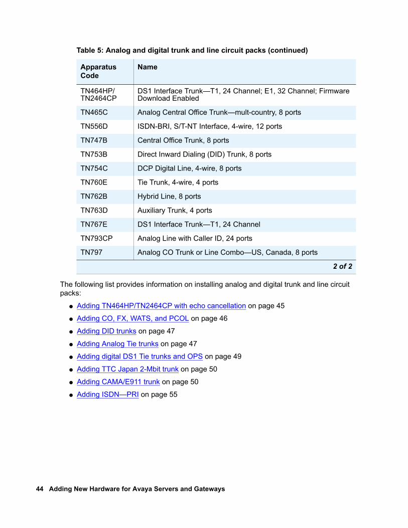
The following list provides information on installing analog and digital trunk and line circuit packs:
● Adding TN464HP/TN2464CP with echo cancellation on page 45
● Adding CO, FX, WATS, and PCOL on page 46
● Adding DID trunks on page 47
● Adding Analog Tie trunks on page 47
● Adding digital DS1 Tie trunks and OPS on page 49
● Adding TTC Japan 2-Mbit trunk on page 50
● Adding CAMA/E911 trunk on page 50
● Adding ISDN—PRI on page 55
TN464HP/TN2464CP
DS1 Interface Trunk—T1, 24 Channel; E1, 32 Channel; Firmware Download Enabled
TN465C Analog Central Office Trunk—mult-country, 8 ports
TN556D ISDN-BRI, S/T-NT Interface, 4-wire, 12 ports
TN747B Central Office Trunk, 8 ports
TN753B Direct Inward Dialing (DID) Trunk, 8 ports
TN754C DCP Digital Line, 4-wire, 8 ports
TN760E Tie Trunk, 4-wire, 4 ports
TN762B Hybrid Line, 8 ports
TN763D Auxiliary Trunk, 4 ports
TN767E DS1 Interface Trunk—T1, 24 Channel
TN793CP Analog Line with Caller ID, 24 ports
TN797 Analog CO Trunk or Line Combo—US, Canada, 8 ports
Table 5: Analog and digital trunk and line circuit packs (continued)
Apparatus Code
Name
2 of 2
Issue 3 January 2008 45
Adding TN464HP/TN2464CP with echo cancellation The TN464HP and TN2464CP circuit packs with echo cancellation are intended for customers who are likely to encounter echo over circuits connected to the Direct Distance Dialing (DDD) network. These circuit packs are intended for channels supporting voice. Therefore, they support the following trunks: CAS, CO, DID, DIOD, DMI, FX, Tie, and WATS. They do not support any data trunk groups.
Note:Note: The P suffix designation means the circuit pack is programmable. New firmware
can be downloaded to the circuit pack.
The TN464HP and TN2464CP circuit packs are backwards compatible. However, the echo cancellation feature can be used only with Release 1.1 or later of Communication Manager and after the feature is enabled.
The echo cancellation feature cancels echoes with delays up to 96 milliseconds. Echo cancellation disables automatically when the circuit pack detects a 2100-hertz phase-reversed tone put out by high-speed modems (56 kilobaud). Echo cancellation does not disable when the circuit pack detects a 2100-hertz straight tone generated by low-speed modems (9.6 kilobaud).
For more information about installing port circuit packs, see Installing the circuit pack on page 52. For more information about setting the option switches, see the job aid titled Option Switch Settings (555-245-774). For more information about circuit pack administration, see Administrator Guide for Avaya Communication Manager (03-300509).
Echo cancellation must first be purchased then activated by the license file. See Administrator Guide for Avaya Communication Manager (03-300509).
To modify the settings:
Note:Note: You do not need to busyout the circuit packs to modify the settings. But the
modified settings do not take effect until either the port is busied out or the scheduled maintenance runs.
1. Type display system-parameters customer-options and press Enter. Verify that the DS1 Echo Cancellation? field is set to y. If not, contact your Avaya representative because the license file determines this setting.
2. Type add ds1 UUCSS, where UUCSS is the cabinet, carrier, and slot location, and press Enter.
3. On the DS1 Circuit Pack screen, set the Echo Cancellation? field to y.
When set to y, the system displays two new fields: EC Direction: and EC Configuration:.● If you know the echo is coming into the system, keep the default setting for the EC
Direction: field of inward.
46 Adding New Hardware for Avaya Servers and Gateways
● If the distant party is hearing echo that originates in either the system, the line side stations, or system equipment, set the EC Direction: field to outward.
● Keep the default setting for the EC Configuration: field.
4. Type add trunk-group next and press Enter.5. On Trunk Features, set the DS1 Echo Cancellation? field to y.
6. Test the voice quality on a telephone connected through the TN464HP or TN2464CP circuit packs and known to have echo to determine if the echo was eliminated.
7. If the echo still exists, reset the EC Configuration: field and test the voice quality. These settings provide help for the following scenarios:
● Setting 1 rapidly minimizes echo when first detected, regardless of how loud the speaker talks. Settings 1 and 4 have the same EC settings except that Setting 1 introduces 6 dB of loss.
● Setting 2 minimizes speech clipping, but it takes a fraction of a second longer for the echo to fade.
● Setting 3 eliminates speech clipping, but a strong echo might take 2 or 3 seconds to fade.
● Setting 4 minimizes strong echo, hot signals, or excessive clipping or breakup of speech from a distant party. It reduces speech clipping but might allow slight residual echo or more background noise.
8. If the echo still exists after you try all these settings, contact technical support.
Adding CO, FX, WATS, and PCOL Each of the following trunks connects to one port of an 8-port TN747B Central Office trunk or to one of an assortment of North American Central Office trunk circuit packs:
● Central Office (CO) trunk
● Foreign Exchange (FX) trunk
● Personal Central Office Line (PCOL)
● Wide Area Telecommunications Service (WATS) trunk
Before physically installing the circuit pack, you need the assigned slot location (UUCSS). UU is the media gateway (MCC1) or port network number (G650). C is the media gateway (G650) or carrier (MCC1). SS is the slot location. This information is available from the person who administered the translations, most likely the software specialist. If the information is not available, you can find the information on the Trunk Group Status screen.
1. Get the trunk group number from the administrator.
2. Type status trunk-group number and press Enter.
Issue 3 January 2008 47
3. Install the CO trunk circuit pack in the assigned carrier slot.
Use the correct type of trunk circuit pack with enough ports to handle the number of trunks you need. For more information about how to find out how many circuit packs you need, see the Hardware Description and Reference for Avaya Communication Manager (555-245-207).
4. Administer the screens listed under Adding a CO, FX, or WATS Trunk Group and Adding a PCOL Trunk Group in the Administrator Guide for Avaya Communication Manager (03-300509).
Adding DID trunks Each Direct Inward Dial (DID) trunk connects to either:
● one port of a DID Trunk circuit pack
or
● one port of an assortment of global DID/DIOD trunk circuit packs.
Before physically installing the circuit pack, you need the assigned slot location (UUCSS). UU is the media gateway (MCC1) or port network number (G650). C is the media gateway (G650) or carrier (MCC1). SS is the slot location. The information is available from the person who administered the translations, most likely the software specialist. If the information is not available, you can find the information on the Trunk Group Status screen.
1. Get the trunk group number from the administrator.
2. Type status trunk-group number and press Enter. 3. Install a DID/DIOD trunk circuit pack in the assigned carrier slot.
4. Administer the screens listed under Adding a DID Trunk Group in the Administrator Guide for Avaya Communication Manager (03-300509).
Adding Analog Tie trunks Each analog tie trunk connects to 1 port of a 4-port tie trunk circuit pack or to an assortment of global tie trunk circuit packs.
Before physically installing the circuit pack, you need the assigned slot location (UUCSS). UU is the media gateway (MCC1) or port network number (G650). C is the media gateway (G650) or carrier (MCC1). SS is the slot location. The information is available from the person who
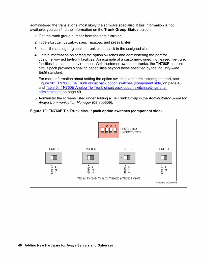
48 Adding New Hardware for Avaya Servers and Gateways
administered the translations, most likely the software specialist. If this information is not available, you can find the information on the Trunk Group Status screen.
1. Get the trunk group number from the administrator.
2. Type status trunk-group number and press Enter. 3. Install the analog or global tie trunk circuit pack in the assigned slot.
4. Obtain information on setting the option switches and administering the port for customer-owned tie-trunk facilities. An example of a customer-owned, not leased, tie-trunk facilities is a campus environment. WIth customer-owned tie-trunks, the TN760E tie trunk circuit pack provides signaling capabilities beyond those specified by the industry-wide E&M standard.
For more information about setting the option switches and administering the port, see Figure 10: TN760E Tie Trunk circuit pack option switches (component side) on page 48 and Table 6: TN760E Analog Tie Trunk circuit pack option switch settings and administration on page 49.
5. Administer the screens listed under Adding a Tie Trunk Group in the Administrator Guide for Avaya Communication Manager (03-300509).
Figure 10: TN760E Tie Trunk circuit pack option switches (component side)
swmsjump LAO 080603
1 2 3 4PROTECTEDUNPROTECTED
PORT 1
SM
PLX
E &
M
1
PORT 2
SM
PLX
E &
M
1
PORT 3
SM
PLX
E &
M
1
PORT 4
SM
PLX
E &
M
1
TN760, TN760B, TN760C, TN760D & TN760E V1-V2
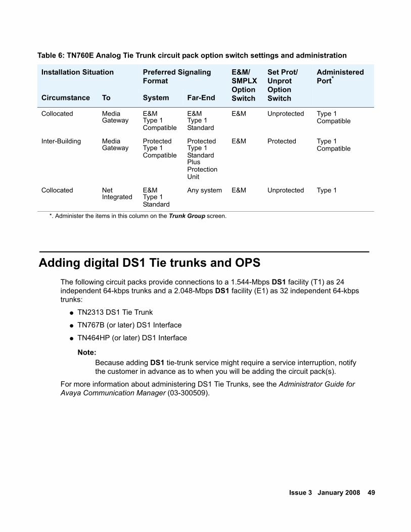
Issue 3 January 2008 49
Adding digital DS1 Tie trunks and OPS The following circuit packs provide connections to a 1.544-Mbps DS1 facility (T1) as 24 independent 64-kbps trunks and a 2.048-Mbps DS1 facility (E1) as 32 independent 64-kbps trunks:
● TN2313 DS1 Tie Trunk
● TN767B (or later) DS1 Interface
● TN464HP (or later) DS1 Interface
Note:Note: Because adding DS1 tie-trunk service might require a service interruption, notify
the customer in advance as to when you will be adding the circuit pack(s).
For more information about administering DS1 Tie Trunks, see the Administrator Guide for Avaya Communication Manager (03-300509).
Table 6: TN760E Analog Tie Trunk circuit pack option switch settings and administration
Installation Situation Preferred Signaling Format
E&M/SMPLX Option Switch
Set Prot/ Unprot Option Switch
Administered Port*
Circumstance To System Far-End
Collocated Media Gateway
E&M Type 1Compatible
E&M Type 1Standard
E&M Unprotected Type 1Compatible
Inter-Building Media Gateway
Protected Type 1Compatible
Protected Type 1Standard PlusProtectionUnit
E&M Protected Type 1Compatible
Collocated Net Integrated
E&M Type 1Standard
Any system E&M Unprotected Type 1
*. Administer the items in this column on the Trunk Group screen.
50 Adding New Hardware for Avaya Servers and Gateways
Adding TTC Japan 2-Mbit trunk The TN2242 Japan 2-Mbit trunk connects the media gateway to other vendor equipment in Japan and to other MultiVantage configurations through the Time Division Multiplexor (TDM).
Before physically installing the circuit pack, you need the assigned slot location (UUCSS). UU is the media gateway (MCC1) or port network number (G650). C is the media gateway (G650) or carrier (MCC1). SS is the slot location. The information is available from the person who administered the translations, most likely the software specialist. If the information is not available, you can find the information on the Trunk Group Status screen.
1. Get the trunk group number from the administrator.
2. Type status trunk-group number and press Enter. 3. Install a TN2242 trunk circuit pack in the assigned slot.
4. Connect the H600-513 cable from the media gateway to the Time Division Multiplexor device.
5. To administer screens, see the Administrator Guide for Avaya Communication Manager (03-300509):
● For ISDN applications, see ISDN Service.
● For non-ISDN applications, see Managing Trunks.
Adding CAMA/E911 trunk The Centralized Automatic Message Accounting (CAMA)/E911 feature requires the TN429C/D (or later) CO Trunk circuit pack.
Port networks in which TN429C/D circuit packs connect to CAMA trunks require some Call Progress Tone Receiver (CPTR) resources to be either TN744D V2 or TN2182B circuit packs. These resources are required because Touch Tone Receiver (TTR)/CPTR or General Purpose Tone Receiver (GPTR) resources are selected from the available pool in the port network when needed.
Table 7: Compatibility Tone Clock, TTR/CPTR, and GPTR circuit packs on page 51 denotes which of these circuit packs are compatible and which are not affected.
Do the following tasks when adding CAMA/E911 trunks:
● Installing the circuit pack on page 52
● Adding the trunks on page 52
● Changing the feature access code on page 52
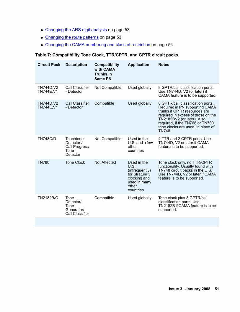
Issue 3 January 2008 51
● Changing the ARS digit analysis on page 53
● Changing the route patterns on page 53
● Changing the CAMA numbering and class of restriction on page 54
Table 7: Compatibility Tone Clock, TTR/CPTR, and GPTR circuit packs
Circuit Pack Description Compatibility with CAMA Trunks in Same PN
Application Notes
TN744D,V2TN744E,V1
Call Classifier - Detector
Not Compatible Used globally 8 GPTR/call classification ports. Use TN744D, V2 (or later) if CAMA feature is to be supported.
TN744D,V2TN744E,V1
Call Classifier - Detector
Compatible Used globally 8 GPTR/call classification ports. Required in PN supporting CAMA trunks if GPTR resources are required in excess of those on the TN2182BV2 (or later). Also required, if the TN768 or TN780 tone clocks are used, in place of TN748.
TN748C/D Touchtone Detector / Call Progress Tone Detector
Not Compatible Used in the U.S. and a few other countries
4 TTR and 2 CPTR ports. Use TN744D, V2 or later if CAMA feature is to be supported.
TN780 Tone Clock Not Affected Used in the U.S. (infrequently) for Stratum 3 clocking and used in many other countries
Tone clock only, no TTR/CPTR functionality. Usually found with TN748 circuit packs in the U.S. Use TN744D, V2 or later if CAMA feature is to be supported.
TN2182B/C Tone Detector/ Tone Generator/ Call Classifier
Compatible Used globally Tone clock plus 8 GPTR/call classification ports. Use TN2182B if CAMA feature is to be supported.
52 Adding New Hardware for Avaya Servers and Gateways
Installing the circuit pack To install the circuit pack:
1. Insert the TN429C or later CO Trunk circuit pack in any available port slot. Ensure that the TN744D Call Classifier/Detector circuit pack is Vintage 2 or later or use the TN744E.
2. Connect the CAMA trunk to the Main Distribution Field, the trunk from the CO. For more information, see the Circuit Pack and Auxiliary Equipment Leads (Pinout Charts) in the job aid titled Connector and Cable Diagrams (Pinout Charts) (555-245-773).
Adding the trunks To add trunks to a group:
Note:Note: So that this trunk group does not get buried within the other trunk groups, use a
distinctive trunk group number such as 99.
1. Type add trunk 99 and press Enter.2. In the Group Type field, type cama.
3. In the Group Name field, type the desired name.
4. In the TAC field, type the desired trunk access code.
5. In the Outgoing Display field, type y.
6. In the CESID I Digits Sent field, type the number directed by the Central Office (CO) or the Public Safety Answering Point (PSAP).
7. Go to the Administrable Timers screen. Adjust these fields according to your CO.
8. Go to the Group Member Assignments screen.
9. In the Port field, add the trunk members.
10. Press F3 when finished to submit the form and effect the changes.
Changing the feature access code To change the feature access code:
1. Type change feature-access-code and press Enter.2. In the Auto Route Selection (ARS) Access Code 1: field, administer the ARS access
code and press Enter. In the example above, it is 9. The ARS access code must match the dial plan.
Issue 3 January 2008 53
Changing the ARS digit analysis To change the ARS digit analysis:
1. Type change ars analysis number and press Enter. The example uses the number 9.
2. In the Dialed String field, in the first empty row, type 11.
3. In the Total Mn field, type 2.
4. In the Total Mx field, type 2.
5. In the Rte Pat field, type the desired Route Pattern. In the example, the route pattern is 11.
Note:Note: For the following step, if you are using the Attendant Crisis Alerting feature, type
alrt instead of emer.
6. In Call Type field, type emer.
7. On the next empty row, in the Dialed String field, type 911.
8. In the Total Mn field, type 3.
9. In the Total Mx field, type 3.
10. In the Rte Pat field, type the desired Route Pattern. In the example, the route pattern is 12.
Note:Note: For the following step, if you are using the Attendant Crisis Alerting feature, type
alrt instead of emer.
11. In the Call Type field, type emer and press Enter.12. Press F3 to submit the screen and effect the changes.
Changing the route patterns To change the route patterns:
1. Type change route-pattern number, the route pattern to be changed, and press Enter. In the example, the route pattern is 11.
2. In the Grp. No. field, type the CAMA trunk group number.
3. In the FRL field, type 0.
Note:Note: For the following step, if the service provider Central Office (CO) wants KP11ST
as the dialed digit string, leave it blank. If the CO wants KP911ST, type 9 in the Inserted Digits field.

54 Adding New Hardware for Avaya Servers and Gateways
4. Administer the Inserted Digits field if needed and press Enter.5. Type change route-pattern number, the route pattern to be changed, and press
Enter. In the example, the route pattern is 12.
6. In Grp. No. field, type the CAMA trunk group number.
7. In the FRL field, type 0.
Note:Note: For the following step, if the service provider Central Office (CO) wants KP911ST
as the dialed digit string, leave blank. If the CO wants KP11ST, delete one digit.
8. Administer No. Del Digits field, if needed.
9. Press F3 to submit the screen and effect the changes.
Changing the CAMA numbering and class of restriction To change the CAMA numbering and class of restriction:
1. Type change cama-numbering and press Enter.2. In the System CESID Default field, type in your own system default.
This system default is the number that the 911 operator sees when the extension code is not found in the CAMA Numbering table.
3. In the Ext Len, Ext Code, CESID, and Total Length fields, fill out to your own CAMA numbering plan. Be sure to cover all extensions.
4. Press F3 to submit the screen and effect the changes.
5. Type change cor number which is the class of restriction (COR) to be changed and press Enter.
6. Change all CORs that are defined for stations to remove any calling party restrictions for 911 calls.
7. In the Calling Party Restriction: field, type none.
8. Press F3 to submit the screen and effect the changes.
9. Type save translations and press Enter. This command takes all translation information in memory and writes it to the hard disk drive.
Issue 3 January 2008 55
Adding ISDN—PRI
North AmericanTo add ISDN-PRI:
1. Install a TN767E (or later) DS1 or a TN464HP DS1/E1 circuit pack for a signaling link and up to 23 ISDN—PRI Trunk Group members.
2. If the port network does not have a TN2312AP IPSI circuit pack, install a TN2182 Tone-Clock circuit pack. The Tone-Clock circuit pack provides synchronization for the DS1 circuit pack.
InternationalTo add ISDN-PRI:
1. Install a TN464HP DS1/E1 circuit pack for the assignment of the 2 signaling channels and up to 30 ISDN — PRI Trunk Group members. Each E1 span provides 32 ports.
2. If the port network does not have a TN2312AP IPSI circuit pack, install a TN2182 Tone-Clock circuit pack. The Tone-Clock circuit pack provides synchronization for the DS1/E1 circuit pack.
Adding circuit packsBefore physically installing the circuit pack, you need the assigned slot location (UUCSS). UU is the media gateway (MCC1, SCC1) or port network number. C is the media gateway or carrier (MCC1). SS is the slot location. The information is available from the person who administered the translations, most likely the software specialist. If the information is not available, you can find the information on the Trunk Group Status screen.
1. Get the trunk group number from the administrator.
2. Type status trunk-group number and press Enter. 3. Install the DS1 Interface circuit pack in the assigned slot.
4. Install a Tone Detector circuit pack, if required.
56 Adding New Hardware for Avaya Servers and Gateways
Connecting cablesTo connect the cables to the MDF:
1. Install and connect cables from the TN464HP to the Main Distribution Field as required.
Administering the circuit packTo administer the circuit pack:
1. Administer the screens listed under ISDN Trunk Group and Trunk Group screens in the Administrator Guide for Avaya Communication Manager (03-300509). These screens are described in the Screen Reference chapter.
Resolving alarmsTo display the alarms:
1. Type display alarms and press Enter.2. Examine the alarm log. Resolve any alarms that might exist using the appropriate
maintenance documentation.
Saving translationsTo save translations:
1. Type save translation and press Enter. This command takes all translation information in memory and writes it to the hard disk drive.
Issue 3 January 2008 57
Chapter 5: Port networks
This chapter contains information and procedures for adding a port network to an existing system. The new port network consists of 1 to 5 TDM-cabled G650 Media Gateways.
To add a port network complete the following tasks:
● Installing a G650 Media Gateway on page 58
● Installing the IPSI circuit pack on page 58
● Assigning IP addresses to the IPSI circuit packs on page 58
● Administering the port network on page 66
● Installing additional circuit packs on page 69
There are three options for port networks:
● All fiber port network connectivity (fiber-PNC) port networks
● All IP-PNC port networks
● A combination of fiber-PNC and IP-PNC port networks
Fiber-PNC port networks include direct-connected PNs, Center Stage Switch (CSS)-connected PNs or Asynchronous Transfer Mode (ATM)-connected PNs.
Starting with Avaya Communication Manager Release 3.0, you can combine IP-PNC and fiber-PNC configurations. The S8700-series and S8500 Servers support configurations that combine IP-PNC with fiber-PNC systems. Additionally, the servers can support configurations that contain
● single control networks,
● duplicated control networks,
● single IP-PNC bearer networks,
● duplicated fiber-PNC bearer networks, and
● IP-PNC networks with duplicated control and duplicated bearer.
Note:Note: If you are adding an IP-PNC G650 Media Gateway to a system with fiber-PNC
port networks, you need either a TN2302AP Media Processor or TN2602AP Media Resource 320 circuit pack. The port network with the IPSI circuit pack in a fiber-PNC portion of the system must contain the TN2302AP Media Processor or TN2602AP Media Resource 320 circuit pack.
58 Adding New Hardware for Avaya Servers and Gateways
Installing a G650 Media Gateway For more information about physically installing the G650 Media Gateway(s) and connecting it to the MDF or patch panels, see Installing the Avaya G650 Media Gateway (03-300144).
Installing the IPSI circuit pack Once you have installed all the media gateways, install the TN2312BP IP Server Interface (IPSI) circuit pack in the media gateway. Install this circuit pack in the A position, slot A01.
S8700-series: If you have a duplicated control network, then install a second IPSI in the media gateway in the B position, slot B01.
1. Install the IPSI adapter to the connector associated with slot 1 on the backplane.
2. Insert the TN2312BP IP Server Interface circuit pack into slot 1.
3. Connect a CAT5 cable to the RJ45 connector on the IPSI adapter.
4. If not already connected, connect the other end of the CAT5 cable to the next available port on the Ethernet switch.
5. If customer is using one, connect one end of the serial maintenance cable to the 9-pin serial port connector on the IPSI adapter.
Assigning IP addresses to the IPSI circuit packs Once the IPSI is installed, you must assign an IP address to it.
IP server interface circuit packs get IP addresses in one of two ways:
● Using static IP addressing
● Using dynamic host configuration protocol (DHCP)
The IPSI circuit packs associated with a nondedicated control network use the static addressing method. In rare cases they might use the DHCP addressing method.
The IPSI circuit packs associated with a dedicated control network use the DHCP method. In rare cases they might use the static addressing method.
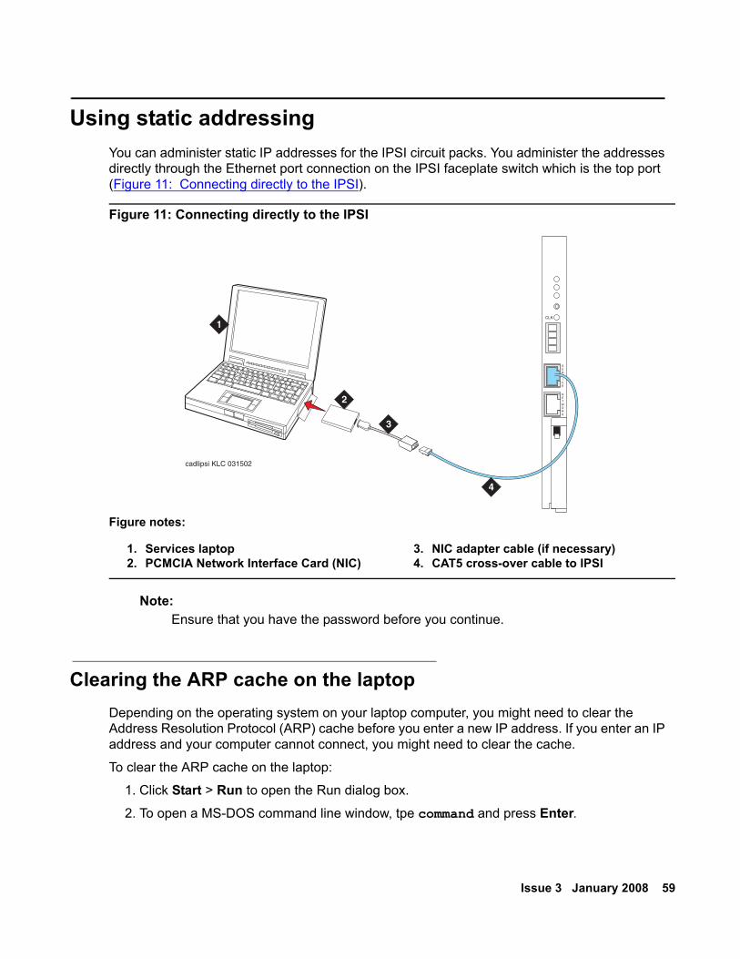
Issue 3 January 2008 59
Using static addressing You can administer static IP addresses for the IPSI circuit packs. You administer the addresses directly through the Ethernet port connection on the IPSI faceplate switch which is the top port (Figure 11: Connecting directly to the IPSI).
Figure 11: Connecting directly to the IPSI
Note:Note: Ensure that you have the password before you continue.
Clearing the ARP cache on the laptop Depending on the operating system on your laptop computer, you might need to clear the Address Resolution Protocol (ARP) cache before you enter a new IP address. If you enter an IP address and your computer cannot connect, you might need to clear the cache.
To clear the ARP cache on the laptop:
1. Click Start > Run to open the Run dialog box.
2. To open a MS-DOS command line window, tpe command and press Enter.
Figure notes:
1. Services laptop2. PCMCIA Network Interface Card (NIC)
3. NIC adapter cable (if necessary)4. CAT5 cross-over cable to IPSI
cadlipsi KLC 031502
1
2
CLK
SERVICE
NETWORK
3
4
60 Adding New Hardware for Avaya Servers and Gateways
3. Type arp -d 192.11.13.6 and press Enter. This command produces one of the following responses:
● The command line prompt when the cache is cleared.
● The message: The specified entry was not found when the specified IP address does not currently appear in the ARP cache.
4. To access the server, type ping -t 192.11.13.6. The -t causes the ping to repeat until you get a response. When you get a response, in about 3 minutes, wait an additional 30 seconds before going back to the Web interface.
5. To stop the ping, type ctrl c.
6. Close the MS-DOS window.
Logging into the IPSITo log into the IPSI:
1. Connect to the IPSI using SSH, with the IP address 192.11.13.6.
Prompt = [IPSI]:
Note:Note: Most commands have abbreviations. For more help while you are connected to
the IPSI, you can type help or ?.
2. Type ipsilogin and press Enter. The abbreviated command is il.
Note:Note: The craft login that you use on the IPSI has a different password than the craft
login used on the servers.
3. Log in as craft.
Prompt = [IPADMIN]:
Setting the control interfaceTo set the control interface:
1. Type show control interface and press Enter.2. To see the current settings, type show port 1 and press Enter.
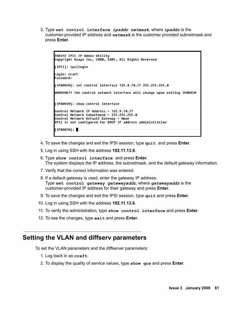
Issue 3 January 2008 61
3. Type set control interface ipaddr netmask, where ipaddr is the customer-provided IP address and netmask is the customer provided subnetmask and press Enter.
4. To save the changes and exit the IPSI session, type quit and press Enter.5. Log in using SSH with the address 192.11.13.6.
6. Type show control interface and press Enter.The system displays the IP address, the subnetmask, and the default gateway information.
7. Verify that the correct information was entered.
8. If a default gateway is used, enter the gateway IP address. Type set control gateway gatewayaddr, where gatewayaddr is the customer-provided IP address for their gateway and press Enter.
9. To save the changes and exit the IPSI session, type quit and press Enter.10. Log in using SSH with the address 192.11.13.6.
11. To verify the administration, type show control interface and press Enter.12. To see the changes, type exit and press Enter.
Setting the VLAN and diffserv parametersTo set the VLAN parameters and the diffserver parameters:
1. Log back in as craft.
2. To display the quality of service values, type show qos and press Enter.
62 Adding New Hardware for Avaya Servers and Gateways
3. If necessary, use the following commands to set the VLAN and diffserv parameters to the recommended values shown.
Note:Note: Use Help to obtain syntax guidelines for these commands.
● Type set vlan priority 6
● Type set diffserv 46
● Type set vlan tag on
● Type set port negotiation 1 disable
● Type set port duplex 1 full
● Type set port speed 1 100
4. To check the administered values, type show qos and press Enter.5. To exit, type quit and press Enter.
! Important:Important: Ensure that the port settings on the Ethernet switches are set to the same values
as shown in the set port commands in step 3.
Using DHCP addressing So that the TN2312BP IPSI circuit packs can receive IP addresses dynamically, you must assign the switch ID and the cabinet number to each IPSI circuit pack. The switch ID is A through J. The cabinet number is 01 through 64. For G650 Media Gateways, a cabinet is defined as one or more media gateways connected by TDM cable. This cabinet configuration is called a G650 rack mount stack.
Administering the location assignmentTo administer the location assignment:
1. Fully insert the TN2312BP IPSI circuit pack. If necessary, reseat the circuit pack to start the programming sequence.
Note:Note: You must start the following steps within 5 seconds after you insert the circuit
pack.
Note:Note: For the following step, do not use a graphite pencil.
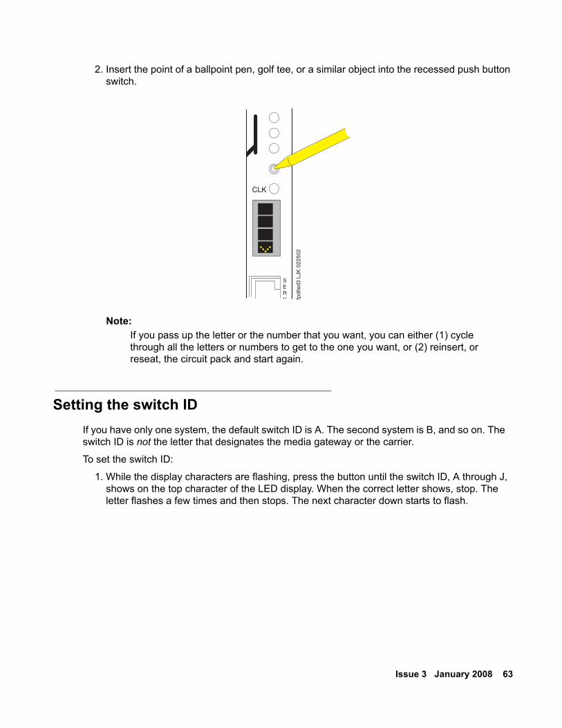
Issue 3 January 2008 63
2. Insert the point of a ballpoint pen, golf tee, or a similar object into the recessed push button switch.
Note:Note: If you pass up the letter or the number that you want, you can either (1) cycle
through all the letters or numbers to get to the one you want, or (2) reinsert, or reseat, the circuit pack and start again.
Setting the switch IDIf you have only one system, the default switch ID is A. The second system is B, and so on. The switch ID is not the letter that designates the media gateway or the carrier.
To set the switch ID:
1. While the display characters are flashing, press the button until the switch ID, A through J, shows on the top character of the LED display. When the correct letter shows, stop. The letter flashes a few times and then stops. The next character down starts to flash.
CLK
SERV fp
dlle
d3 L
JK 0
2250
2
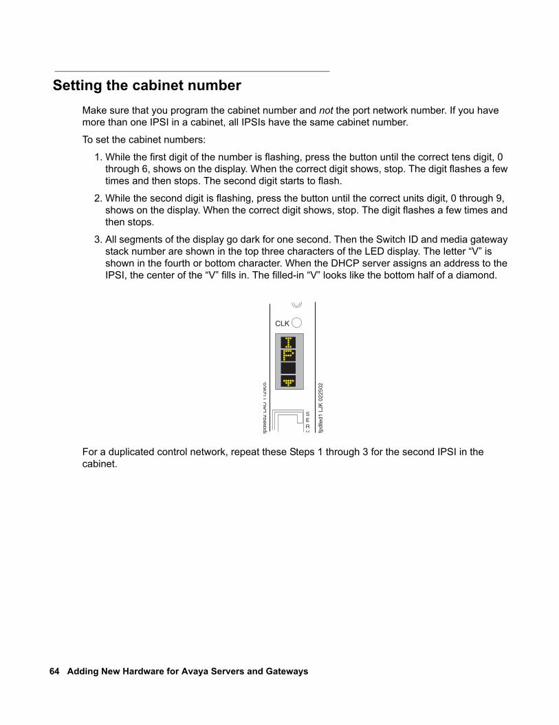
64 Adding New Hardware for Avaya Servers and Gateways
Setting the cabinet numberMake sure that you program the cabinet number and not the port network number. If you have more than one IPSI in a cabinet, all IPSIs have the same cabinet number.
To set the cabinet numbers:
1. While the first digit of the number is flashing, press the button until the correct tens digit, 0 through 6, shows on the display. When the correct digit shows, stop. The digit flashes a few times and then stops. The second digit starts to flash.
2. While the second digit is flashing, press the button until the correct units digit, 0 through 9, shows on the display. When the correct digit shows, stop. The digit flashes a few times and then stops.
3. All segments of the display go dark for one second. Then the Switch ID and media gateway stack number are shown in the top three characters of the LED display. The letter “V” is shown in the fourth or bottom character. When the DHCP server assigns an address to the IPSI, the center of the “V” fills in. The filled-in “V” looks like the bottom half of a diamond.
For a duplicated control network, repeat these Steps 1 through 3 for the second IPSI in the cabinet.
fpdl
led2
LA
O 1
1290
5
CLK
SERV fp
dlle
d1 L
JK 0
2250
2
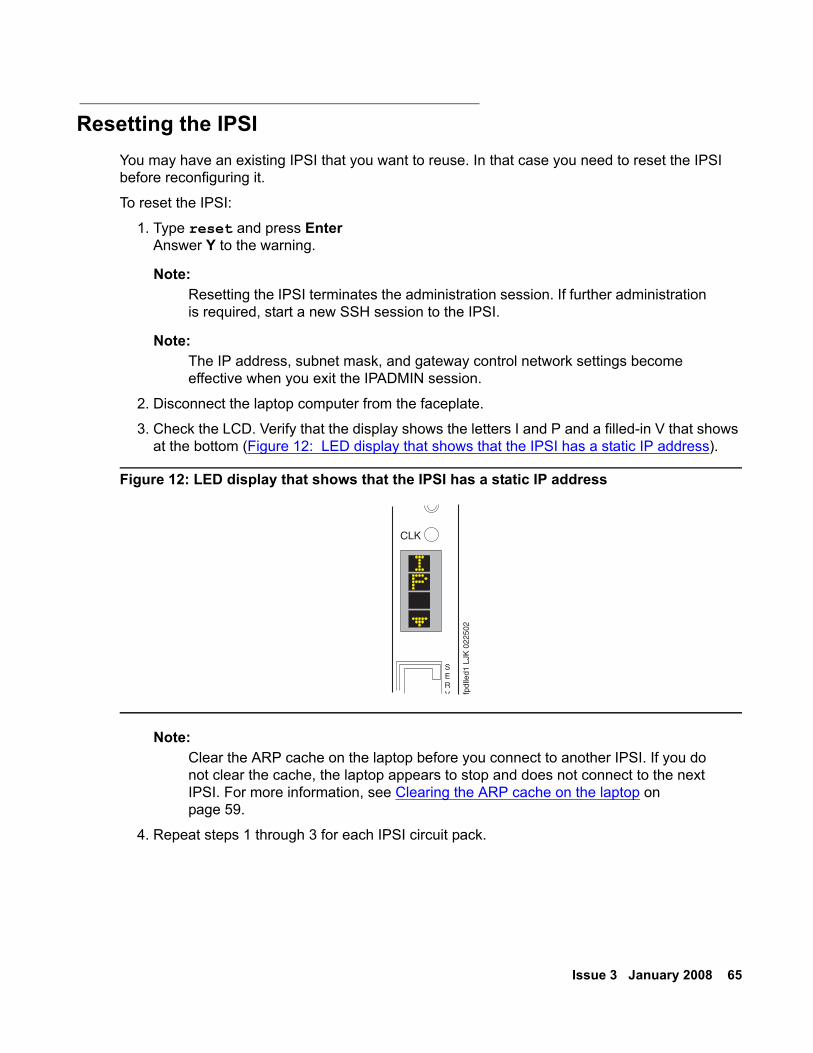
Issue 3 January 2008 65
Resetting the IPSIYou may have an existing IPSI that you want to reuse. In that case you need to reset the IPSI before reconfiguring it.
To reset the IPSI:
1. Type reset and press EnterAnswer Y to the warning.
Note:Note: Resetting the IPSI terminates the administration session. If further administration
is required, start a new SSH session to the IPSI.
Note:Note: The IP address, subnet mask, and gateway control network settings become
effective when you exit the IPADMIN session.
2. Disconnect the laptop computer from the faceplate.
3. Check the LCD. Verify that the display shows the letters I and P and a filled-in V that shows at the bottom (Figure 12: LED display that shows that the IPSI has a static IP address).
Figure 12: LED display that shows that the IPSI has a static IP address
Note:Note: Clear the ARP cache on the laptop before you connect to another IPSI. If you do
not clear the cache, the laptop appears to stop and does not connect to the next IPSI. For more information, see Clearing the ARP cache on the laptop on page 59.
4. Repeat steps 1 through 3 for each IPSI circuit pack.
CLK
SERV fp
dlle
d1 L
JK 0
2250
2
66 Adding New Hardware for Avaya Servers and Gateways
Administering the port network Once the port network is installed, you must add translation information to the server. Use Secure Shell to access SAT commands.
Note:Note: For port networks using G650 Media Gateways, a cabinet is defined as up to 5
G650 Media Gateways mounted in a rack and TDM-connected.
1. Type add cabinet number where number is the next available number, up to 64, and press Enter.
Note:Note: When you install a IP-PNC G650 Media Gateway into a fiber-PNC port network
the IP-PNC? field on the Customer Options screen must be set to n. The customer license file determines this setting. With this field set to n, the maximum number of port networks in the system can be 64. This maximum is possible even if direct-, ATM- or CSS-connected port networks exist in the configuration.
2. Fill in the location and carrier type for media gateways 2, 3, 4, and 5.
3. Repeat steps 1 through 3 for each G650 media gateway stack controlled by one TN2312BP IPSI circuit pack.
Adding IPSI translations to Communication Manager To add IPSI translations to Communication Manager.
1. Type add ipserver-interface PN where PN is the port network 1-64 and press Enter to add the IPSI circuit pack information.
2. When using a DHCP server, verify that the fields associated with the Primary IPSI and Secondary IPSI, if equipped, are populated with default data. Set the Host: and DHCP ID: fields through the DHCP server.
3. When using static addressing, in the Host: field, type in the IP address for the IPSI. This IPSI is located in the port network and is listed in the Location: field.
4. If the port network is IP-PNC, set the IP Control? field to y. Then, an IP-PNC port network can be synchronized with fiber-PNC port networks.
or
If the port network is fiber-PNC only, with no IP-PNC port networks in the system, set the IP Control? field to n. You cannot type n in this field unless one or more fiber links have been administered in the media gateway that houses the IPSI circuit pack.
Issue 3 January 2008 67
5. Verify that all the other fields are populated.
6. Press Enter to effect the changes.
7. Repeat steps 1 through 6 for each port network.
Set IPSI duplication (duplicated control network only) Perform the following tasks if you are adding a duplicated control PN to an existing port network system. These port networks can be fiber-PNC or IP-PNC.
Starting with Avaya Communication Manager Release 3.0, you can combine fiber-PNC and IP-PNC duplicate control PNs. For example, you can combine a duplicated control fiber-PNC PN with an existing single-control IP-PNC system.
Note:Note: If you set IPSI duplication in a system with both fiber-PNC PNs and IP-PNC port
networks, you may need to perform further administration to configure the control networks. For more information, see Administration for Network Connectivity for Avaya Communication Manager (555-233-504).
To enable IPSI duplication in a duplicated control network.
1. Type change system-parameters duplication and press Enter.The system displays the following screen when the IP-PNC? field on the Customer Options screen is set to n. Set the IP-PNC? field to n if either of the following conditions are true:
● any of the port networks in your system are fiber-PNC
or
● you anticipate that you will add fiber-PNC port networks in the future
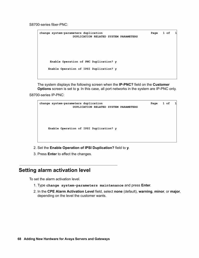
68 Adding New Hardware for Avaya Servers and Gateways
S8700-series fiber-PNC:
The system displays the following screen when the IP-PNC? field on the Customer Options screen is set to y. In this case, all port networks in the system are IP-PNC only.
S8700-series IP-PNC:
2. Set the Enable Operation of IPSI Duplication? field to y.
3. Press Enter to effect the changes.
Setting alarm activation level To set the alarm activation level.
1. Type change system-parameters maintenance and press Enter.2. In the CPE Alarm Activation Level field, select none (default), warning, minor, or major,
depending on the level the customer wants.
change system-parameters duplication Page 1 of 1 DUPLICATION RELATED SYSTEM PARAMETERS
Enable Operation of PNC Duplication? y
Enable Operation of IPSI Duplication? y
change system-parameters duplication Page 1 of 1 DUPLICATION RELATED SYSTEM PARAMETERS
Enable Operation of IPSI Duplication? y
Issue 3 January 2008 69
Verifying IPSI translations To verify that the IPSI recognized by Communication Manager.
1. Type list ipserver-interface and press Enter.2. Verify that the ISPI circuit pack(s) is translated.
Verifying IPSI connectivity To verify that the IPSI is connected to the network.
1. Under Diagnostics, click Ping.
2. Select IPSIs with cab number (1–99) ___ carrier number ___. Fill in the blanks with the correct cabinet and carrier numbers.
3. Click Execute Ping.
4. Verify that the endpoints respond correctly.
Installing additional circuit packs If the customer is adding circuit packs, install them now. For more information about installing and administering various circuit packs, see Chapter 2: IP connectivity hardware on page 11.

70 Adding New Hardware for Avaya Servers and Gateways
Issue 3 January 2008 71
Chapter 6: Adjuncts and peripherals
This chapter provides procedures for installing software (adjuncts) and equipment (peripherals) to Avaya servers and media gateways. Not all adjuncts and peripherals are addressed here. For more information about the adjuncts and peripherals not addressed in this document, we are supplying other resources for the information.
Avaya servers and media gateways can work with a wide range of external equipment, applications, and peripherals. For the purpose of this chapter, we define the terms as follows:
● Adjuncts are software products that work with the various Avaya servers or media gateways.
● Peripherals are hardware products that connect directly or remotely to Avaya servers or media gateways.
Be aware that some equipment and software work only with certain releases. See your Avaya representative for the most current compatibility information.
Terminal server installation This section provides information about connecting adjunct equipment to the C-LAN circuit pack or Internet connection on the S8300 Server using a terminal server (Figure 13: Switch-to-adjunct LAN connectivity through a terminal server on page 72). Avaya supports the IOLAN+ 104 terminal server, which is RoHS compliant.
Any device that does not support a direct TCP/IP connection but does support an RS232 interface can connect through a terminal server. System printers, property management systems (PMS), and some CDR devices use RS232 connections and can connect through a terminal server.
You can connect up to four adjuncts through one terminal server.
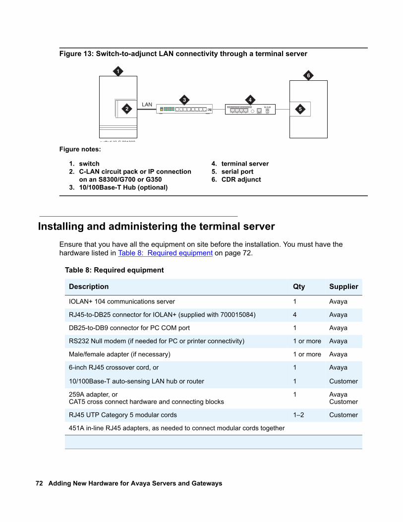
72 Adding New Hardware for Avaya Servers and Gateways
Figure 13: Switch-to-adjunct LAN connectivity through a terminal server
Installing and administering the terminal serverEnsure that you have all the equipment on site before the installation. You must have the hardware listed in Table 8: Required equipment on page 72.
Figure notes:
1. switch2. C-LAN circuit pack or IP connection
on an S8300/G700 or G3503. 10/100Base-T Hub (optional)
4. terminal server5. serial port6. CDR adjunct
LAN
cydfadj KLC 091302
1
2 5
6
3DATA CONNECTIONS ONLY - NOT FOR TELECOM USE
1 2 3 4 10BASE-T 5VDC
4
Table 8: Required equipment
Description Qty Supplier
IOLAN+ 104 communications server 1 Avaya
RJ45-to-DB25 connector for IOLAN+ (supplied with 700015084) 4 Avaya
DB25-to-DB9 connector for PC COM port 1 Avaya
RS232 Null modem (if needed for PC or printer connectivity) 1 or more Avaya
Male/female adapter (if necessary) 1 or more Avaya
6-inch RJ45 crossover cord, or
10/100Base-T auto-sensing LAN hub or router
1
1
Avaya
Customer
259A adapter, orCAT5 cross connect hardware and connecting blocks
1 AvayaCustomer
RJ45 UTP Category 5 modular cords 1–2 Customer
451A in-line RJ45 adapters, as needed to connect modular cords together
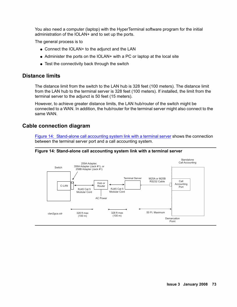
Issue 3 January 2008 73
You also need a computer (laptop) with the HyperTerminal software program for the initial administration of the IOLAN+ and to set up the ports.
The general process is to
● Connect the IOLAN+ to the adjunct and the LAN
● Administer the ports on the IOLAN+ with a PC or laptop at the local site
● Test the connectivity back through the switch
Distance limits
The distance limit from the switch to the LAN hub is 328 feet (100 meters). The distance limit from the LAN hub to the terminal server is 328 feet (100 meters). If installed, the limit from the terminal server to the adjunct is 50 feet (15 meters).
However, to achieve greater distance limits, the LAN hub/router of the switch might be connected to a WAN. In addition, the hub/router for the terminal server might also connect to the same WAN.
Cable connection diagram
Figure 14: Stand-alone call accounting system link with a terminal server shows the connection between the terminal server port and a call accounting system.
Figure 14: Stand-alone call accounting system link with a terminal server
clan2gca.cdr 50 Ft. Maximum
StandaloneCall Accounting
CallAccounting
Port
DemarcationPoint
M25A or M25BRS232 Cable
«C-LAN
Switch
Hub orRouter
328 ft max(100 m)
328 ft max(100 m)
AC Power
Terminal Server
RJ45 Cat 5Modular Cord
RJ45 Cat 5Modular Cord
259A Adapter,356A Adapter (Jack #1), or
258B Adapter (Jack #1)
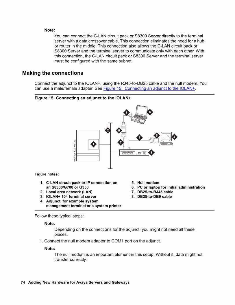
74 Adding New Hardware for Avaya Servers and Gateways
Note:Note: You can connect the C-LAN circuit pack or S8300 Server directly to the terminal
server with a data crossover cable. This connection eliminates the need for a hub or router in the middle. This connection also allows the C-LAN circuit pack or S8300 Server and the terminal server to communicate only with each other. With this connection, the C-LAN circuit pack or S8300 Server and the terminal server must be configured with the same subnet.
Making the connections
Connect the adjunct to the IOLAN+, using the RJ45-to-DB25 cable and the null modem. You can use a male/female adapter. See Figure 15: Connecting an adjunct to the IOLAN+.
Figure 15: Connecting an adjunct to the IOLAN+
Follow these typical steps:
Note:Note: Depending on the connections for the adjunct, you might not need all these
pieces.1. Connect the null modem adapter to COM1 port on the adjunct.
Note:Note: The null modem is an important element in this setup. Without it, data might not
transfer correctly.
Figure notes:
1. C-LAN circuit pack or IP connection on an S8300/G700 or G350
2. Local area network (LAN)3. IOLAN+ 104 terminal server4. Adjunct, for example system
management terminal or a system printer
5. Null modem6. PC or laptop for initial administration7. DB25-to-RJ45 cable8. DB25-to-DB9 cable
cydf
rcon
KLC
021
201
1
2
4
DATA CONNECTIONS ONLY - NOT FOR TELECOM USE
1 2 3 4 10BASE-T 5VDC
3
7
7
8
5
5
6
Issue 3 January 2008 75
2. Connect the other end of the null modem adapter to the DB25 to RJ45 cable.
3. Connect the RJ45 end to any port on the IOLAN+.
Administering the IOLAN+
To administer the IOLAN+ the first time, you must connect a PC or laptop to the RS232 Port 1 on the IOLAN+ terminal server. Follow these typical steps:
Note:Note: Depending on the COM port of the computer, you might not need all these
pieces.
1. Connect the DB9 end of the DB9-to-DB25 cable to the COM port on the PC or laptop.
2. Connect the DB25 end to the null modem adapter.
3. Connect the other end of the null modem adapter to the DB25 to RJ45 cable.
4. Connect the RJ45 end to Port 1 of the IOLAN+.
Before starting the initial administration, ensure that you have the following information:
● New IP address and subnet mask for IOLAN+
● Host name for IOLAN+
● IP address of C-LAN circuit pack Ethernet interface
● Port number of C-LAN circuit pack Ethernet interface where adjunct connects.
Setting up HyperTerminal on the computerUse the HyperTerminal software program that comes with Windows NT/2000 to administer the IOLAN+.
1. Open HyperTerminal.
2. Click File > Properties > Connect tab. In the Connect using: field, select COM n, where n is the communication port your computer is using.
3. Click CONFIGURE and set the bits per second field to 9600 and the Flow control field to Hardware.
4. Click OK.
5. Press Enter to get the login prompt.
Navigating the IOLAN+ terminal serverFor more information, see the IOLAN+ user guide. Usually, you follow these steps:
● Use the arrow keys to move to a menu item
● Use the TAB key to move from field to field horizontally.
● Use the Enter key to choose an item.
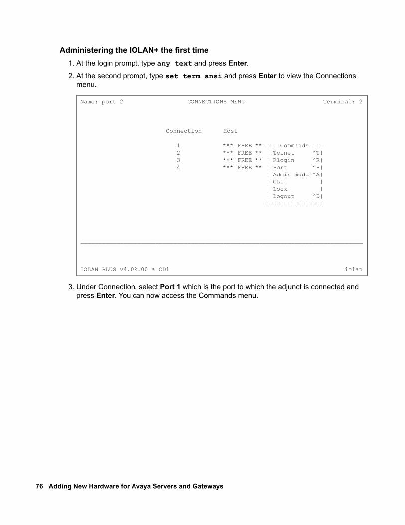
76 Adding New Hardware for Avaya Servers and Gateways
Administering the IOLAN+ the first time1. At the login prompt, type any text and press Enter.2. At the second prompt, type set term ansi and press Enter to view the Connections
menu.
3. Under Connection, select Port 1 which is the port to which the adjunct is connected and press Enter. You can now access the Commands menu.
Name: port 2 CONNECTIONS MENU Terminal: 2
Connection Host
1 *** FREE ** === Commands === 2 *** FREE ** | Telnet ^T| 3 *** FREE ** | Rlogin ^R| 4 *** FREE ** | Port ^P| | Admin mode ^A| | CLI | | Lock | | Logout ^D| ================
_______________________________________________________________________________
IOLAN PLUS v4.02.00 a CDi iolan
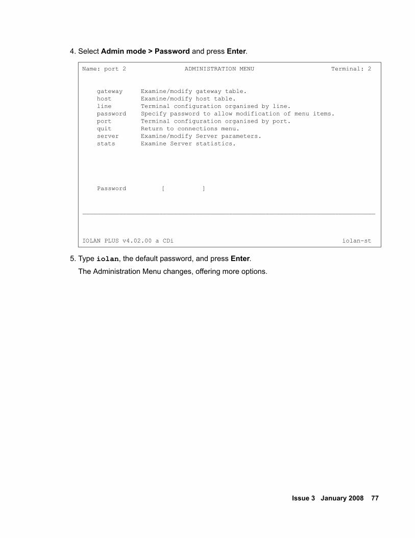
Issue 3 January 2008 77
4. Select Admin mode > Password and press Enter.
5. Type iolan, the default password, and press Enter.The Administration Menu changes, offering more options.
Name: port 2 ADMINISTRATION MENU Terminal: 2
gateway Examine/modify gateway table. host Examine/modify host table. line Terminal configuration organised by line. password Specify password to allow modification of menu items. port Terminal configuration organised by port. quit Return to connections menu. server Examine/modify Server parameters. stats Examine Server statistics.
Password [ ]
________________________________________________________________________________
IOLAN PLUS v4.02.00 a CDi iolan-st
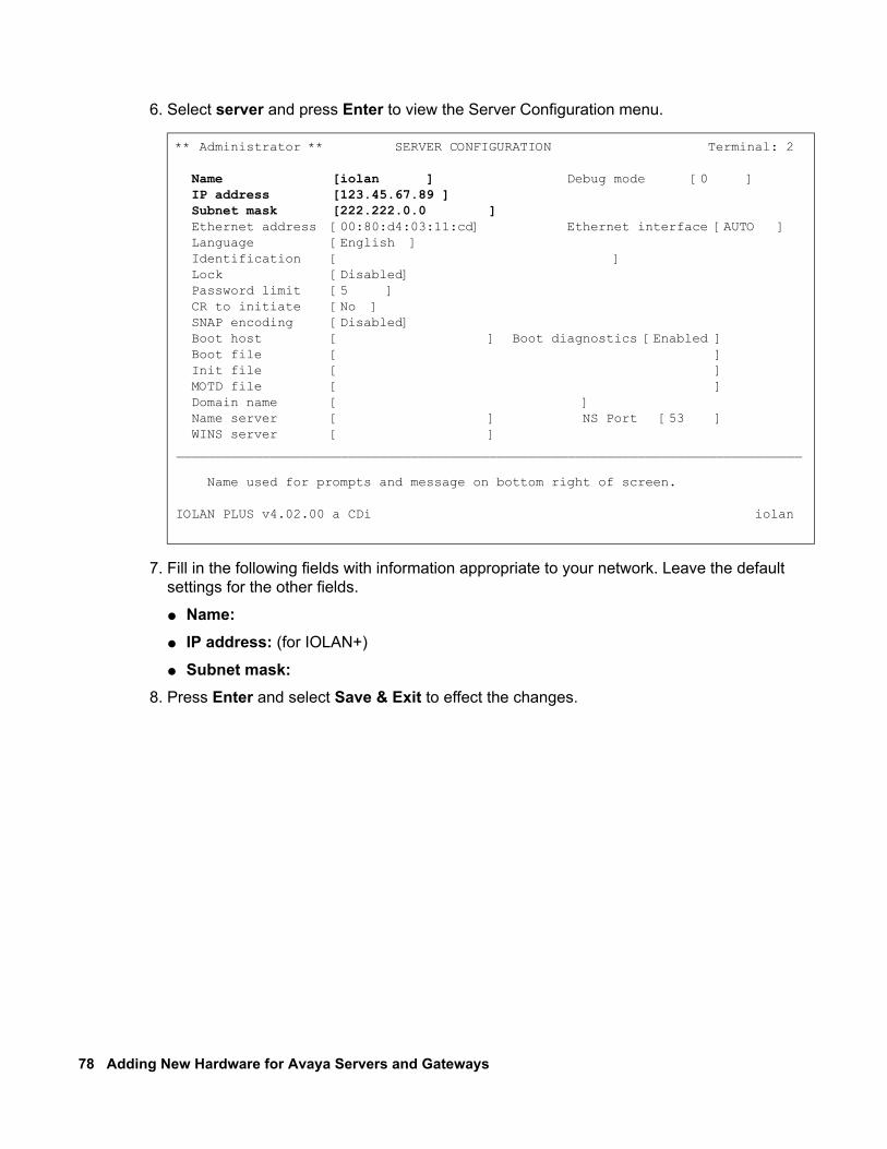
78 Adding New Hardware for Avaya Servers and Gateways
6. Select server and press Enter to view the Server Configuration menu.
7. Fill in the following fields with information appropriate to your network. Leave the default settings for the other fields.
● Name: ● IP address: (for IOLAN+)
● Subnet mask:8. Press Enter and select Save & Exit to effect the changes.
** Administrator ** SERVER CONFIGURATION Terminal: 2
Name [iolan ] Debug mode [0 ] IP address [123.45.67.89 ] Subnet mask [222.222.0.0 ] Ethernet address [00:80:d4:03:11:cd] Ethernet interface [AUTO ] Language [English ] Identification [ ] Lock [Disabled] Password limit [5 ] CR to initiate [No ] SNAP encoding [Disabled] Boot host [ ] Boot diagnostics [Enabled ] Boot file [ ] Init file [ ] MOTD file [ ] Domain name [ ] Name server [ ] NS Port [53 ] WINS server [ ]________________________________________________________________________________
Name used for prompts and message on bottom right of screen.
IOLAN PLUS v4.02.00 a CDi iolan
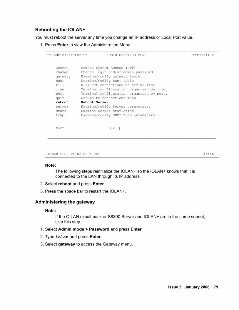
Issue 3 January 2008 79
Rebooting the IOLAN+ You must reboot the server any time you change an IP address or Local Port value.
1. Press Enter to view the Administration Menu.
Note:Note: The following steps reinitialize the IOLAN+ so the IOLAN+ knows that it is
connected to the LAN through its IP address.
2. Select reboot and press Enter.3. Press the space bar to restart the IOLAN+.
Administering the gateway
Note:Note: If the C-LAN circuit pack or S8300 Server and IOLAN+ are in the same subnet,
skip this step.
1. Select Admin mode > Password and press Enter.2. Type iolan and press Enter.3. Select gateway to access the Gateway menu.
** Administrator ** ADMINISTRATION MENU Terminal: 2
access Remote System Access (PPP). change Change login and/or admin password. gateway Examine/modify gateway table. host Examine/modify host table. kill Kill TCP connections on serial line. line Terminal configuration organised by line. port Terminal configuration organised by port. quit Return to connections menu. reboot Reboot Server. server Examine/modify Server parameters. stats Examine Server statistics. trap Examine/modify SNMP Trap parameters.
Port [2 ]
________________________________________________________________________________
IOLAN PLUS v4.02.00 a CDi iolan
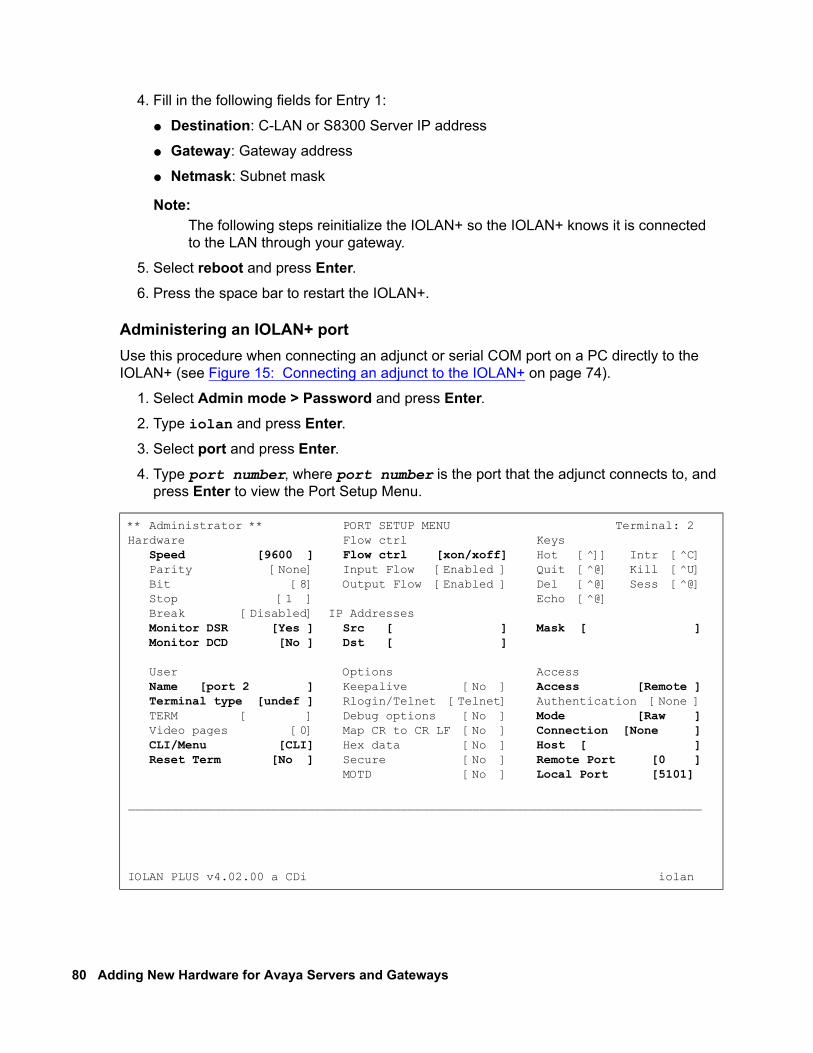
80 Adding New Hardware for Avaya Servers and Gateways
4. Fill in the following fields for Entry 1:
● Destination: C-LAN or S8300 Server IP address
● Gateway: Gateway address
● Netmask: Subnet mask
Note:Note: The following steps reinitialize the IOLAN+ so the IOLAN+ knows it is connected
to the LAN through your gateway.
5. Select reboot and press Enter. 6. Press the space bar to restart the IOLAN+.
Administering an IOLAN+ portUse this procedure when connecting an adjunct or serial COM port on a PC directly to the IOLAN+ (see Figure 15: Connecting an adjunct to the IOLAN+ on page 74).
1. Select Admin mode > Password and press Enter.2. Type iolan and press Enter.3. Select port and press Enter.4. Type port number, where port number is the port that the adjunct connects to, and
press Enter to view the Port Setup Menu.
** Administrator ** PORT SETUP MENU Terminal: 2Hardware Flow ctrl Keys Speed [9600 ] Flow ctrl [xon/xoff] Hot [^]] Intr [^C] Parity [None] Input Flow [Enabled ] Quit [^@] Kill [^U] Bit [8] Output Flow [Enabled ] Del [^@] Sess [^@] Stop [1 ] Echo [^@] Break [Disabled] IP Addresses Monitor DSR [Yes ] Src [ ] Mask [ ] Monitor DCD [No ] Dst [ ]
User Options Access Name [port 2 ] Keepalive [No ] Access [Remote ] Terminal type [undef ] Rlogin/Telnet [Telnet] Authentication [None ] TERM [ ] Debug options [No ] Mode [Raw ] Video pages [0] Map CR to CR LF [No ] Connection [None ] CLI/Menu [CLI] Hex data [No ] Host [ ] Reset Term [No ] Secure [No ] Remote Port [0 ] MOTD [No ] Local Port [5101]
________________________________________________________________________________
IOLAN PLUS v4.02.00 a CDi iolan
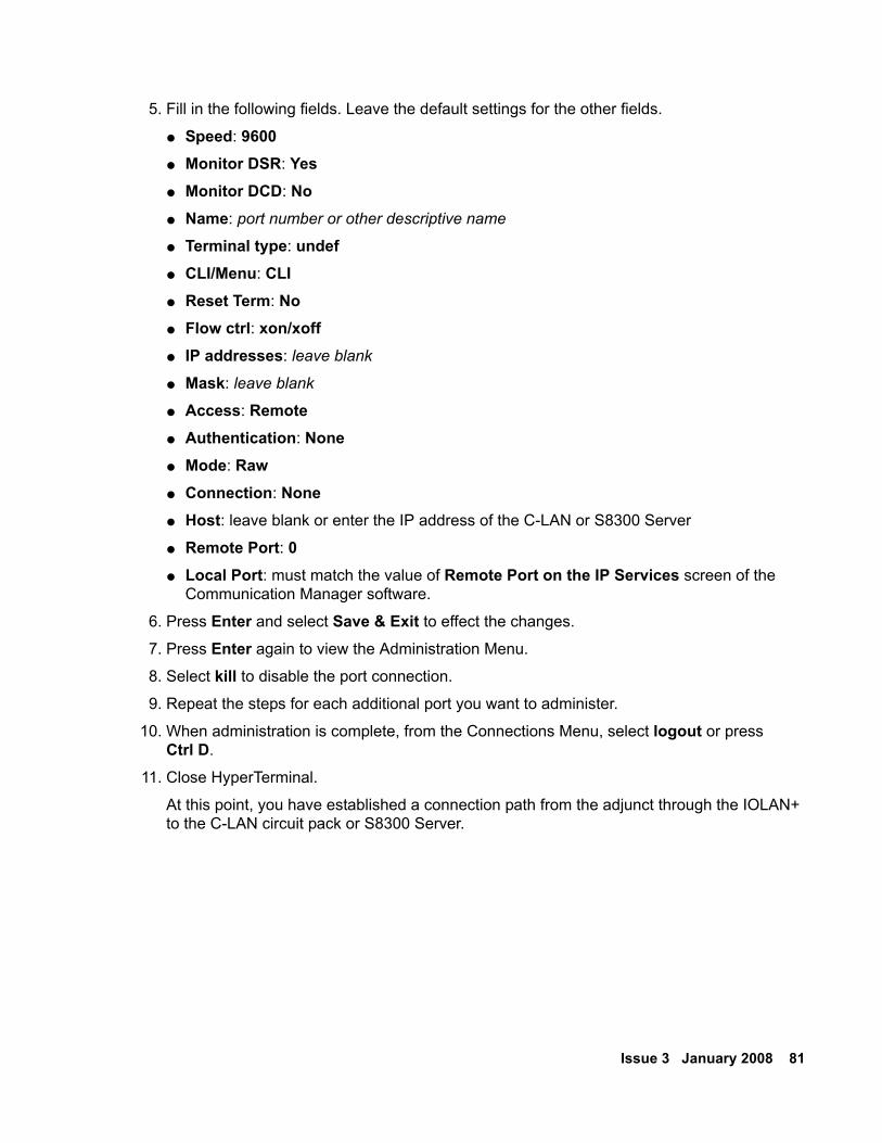
Issue 3 January 2008 81
5. Fill in the following fields. Leave the default settings for the other fields.
● Speed: 9600● Monitor DSR: Yes● Monitor DCD: No● Name: port number or other descriptive name
● Terminal type: undef● CLI/Menu: CLI● Reset Term: No● Flow ctrl: xon/xoff ● IP addresses: leave blank
● Mask: leave blank
● Access: Remote● Authentication: None● Mode: Raw● Connection: None● Host: leave blank or enter the IP address of the C-LAN or S8300 Server
● Remote Port: 0● Local Port: must match the value of Remote Port on the IP Services screen of the
Communication Manager software.
6. Press Enter and select Save & Exit to effect the changes.
7. Press Enter again to view the Administration Menu.
8. Select kill to disable the port connection.
9. Repeat the steps for each additional port you want to administer.
10. When administration is complete, from the Connections Menu, select logout or press Ctrl D.
11. Close HyperTerminal.
At this point, you have established a connection path from the adjunct through the IOLAN+ to the C-LAN circuit pack or S8300 Server.
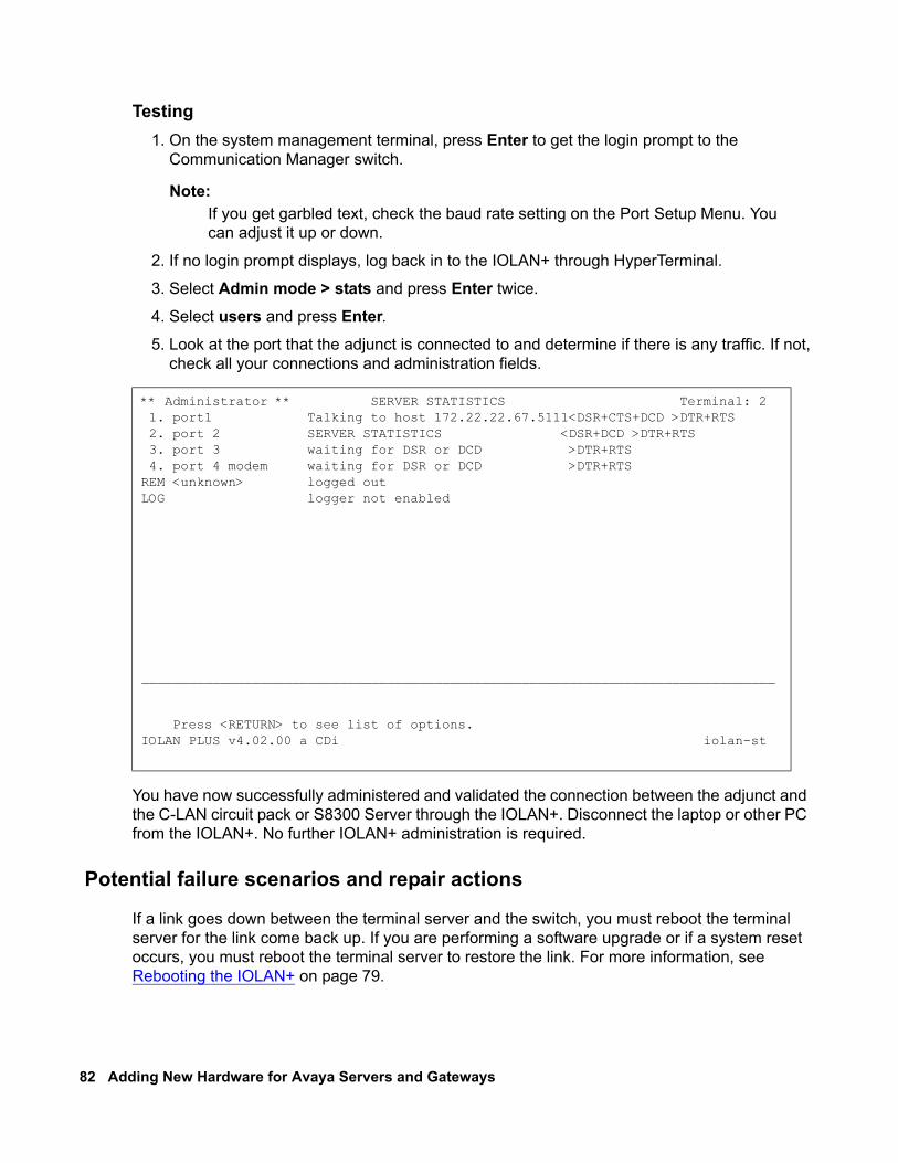
82 Adding New Hardware for Avaya Servers and Gateways
Testing1. On the system management terminal, press Enter to get the login prompt to the
Communication Manager switch.
Note:Note: If you get garbled text, check the baud rate setting on the Port Setup Menu. You
can adjust it up or down.
2. If no login prompt displays, log back in to the IOLAN+ through HyperTerminal.
3. Select Admin mode > stats and press Enter twice.
4. Select users and press Enter.5. Look at the port that the adjunct is connected to and determine if there is any traffic. If not,
check all your connections and administration fields.
You have now successfully administered and validated the connection between the adjunct and the C-LAN circuit pack or S8300 Server through the IOLAN+. Disconnect the laptop or other PC from the IOLAN+. No further IOLAN+ administration is required.
Potential failure scenarios and repair actions
If a link goes down between the terminal server and the switch, you must reboot the terminal server for the link come back up. If you are performing a software upgrade or if a system reset occurs, you must reboot the terminal server to restore the link. For more information, see Rebooting the IOLAN+ on page 79.
** Administrator ** SERVER STATISTICS Terminal: 2 1. port1 Talking to host 172.22.22.67.5111<DSR+CTS+DCD >DTR+RTS 2. port 2 SERVER STATISTICS <DSR+DCD >DTR+RTS 3. port 3 waiting for DSR or DCD >DTR+RTS 4. port 4 modem waiting for DSR or DCD >DTR+RTSREM <unknown> logged outLOG logger not enabled
________________________________________________________________________________
Press <RETURN> to see list of options.IOLAN PLUS v4.02.00 a CDi iolan-st
Issue 3 January 2008 83
Administering IP node namesYou must administer the IP addresses of all of the following components:
● the C-LAN board,
● any adjunct that connects directly to the LAN,
● the terminal server, if appropriate, and
● the PC that runs the Reliable Session-Layer Protocol, if appropriate.
Use the Node Names screen to administer the IP addresses.
1. Type change node-names ip and press RETURN.
2. Type the name and the IP address of the C-LAN board and any adjunct, terminal server or PC you need to administer.
3. Print a copy of this screen, or write down the node names you entered. You need this information for the next administration task.
4. Press Enter to save your changes.
Administering IP servicesFor each adjunct that you connect using TCP/IP, you need to administer IP services to establish the IP address/TCP port pairing. The IP address is associated with the node name that you just administered. In this example, we are administering the primary CDR connection as end-to-end TCP/IP, and the PMS connection through a terminal server.
1. Type change ip-services and press RETURN to assign the CDR endpoint.
2. In the Service Type field, type CDR1 for the call accounting link, and PMS for the property management system.
3. In the Local Node field, type the node name for the switch. In this example, switch-clan is the local node.
4. The Local Port field defaults to 0 for all client applications. You cannot make an entry in this field.
5. In the Remote Node field, type the node name for the adjunct, as administered on the Node Names screen. For the call accounting application, type callacctg. Since the PMS application routes through the terminal server, termserver is the remote node for this service type.
6. In the Remote Port field, type the TCP listen port assigned to the adjunct. The recommended value for CDR1 is 5101, and the recommended value for PMS is 5103.
84 Adding New Hardware for Avaya Servers and Gateways
Note:Note: This number must match the port administered on the end device. If you are
using the Downloadable Reliable Session-Layer Protocol tool, this number must match the port administered in the Server application. If you are using a terminal server, this number must match the Local Port number on the Port Setup menu. Consult the documentation for your Call Accounting system to determine the appropriate port for the CDR device.
7. Move to Page 3. In the Reliable Protocol field, type n for the CDR Service Type. You do not use RSP with a terminal server.
8. Press Enter to save your changes.
Call detail recording (CDR) This section provides information on connecting call detail recording (CDR) equipment.
Connecting CDR EquipmentThe interface between an Avaya server and CDR equipment is a C-LAN card or Processor Ethernet Connection.
CDR equipment connects to the C-LAN circuit pack in a G650 Media Gateway through a TCP/IP connection which is an Ethernet connection. Any CDR equipment that supports the Reliable Session Protocol supports a direct TCP/IP connection. A CDR application that supports an RS232 interface can also connect to the C-LAN through a terminal server. For more information about connecting through a terminal server, see Terminal server installation on page 71.
CDR equipment connects to one of the two IP connections (EXT 1 or EXT 2) on the front of the G700 or G350 Media Gateway. As with C-LAN connections, the CDR adjunct may be a terminal server or a CDR application using RSP.
Note:Note: A printer or customer premises equipment (CPE) can also be used as the output
receiving device. For more information about using a printer, see Terminal server installation on page 71.
Issue 3 January 2008 85
Administering CDR data collection To administer the CDR data collection.
Note:Note: To send CDR data through the C-LAN or a processor Ethernet interface to a
device on the LAN/WAN, you have the option to enable/disable RSP.
1. Setup the CDR adjunct to be ready to collect CDR data. Record the IP address and the port number of the CDR adjunct, which can be a terminal server or a CDR application that uses RSP.
If the CDR adjunct is an application that uses RSP, start the application to listen for a client connection at the port.
2. Access the Node Names screen in Communication Manager. For more information, see Administering IP node names on page 83. Perform the following steps:
a. In the Name field, type the name of the CDR adjunct from step 1.
b. In the Address field, type the IP address of the CDR adjunct.
3. Access the IP Services screen in Communication Manager. For more information, see Administering IP services on page 83. Perform the following steps:
a. In the Service Type field, type CDR1 or CDR2.
b. In the Local Node field, type switch-clan or procr.c. The Local Port field defaults to 0 for all client applications. You cannot make an entry in
this field.
d. In the Remote Node field, type the node name you assigned to the CDR adjunct in step 2.
e. In the Remote Port field, type the port number used by the CDR adjunct determined in step 1.
4. Go to Page 3 and perform the following steps:
a. In the Reliable Protocol field, type y if you have a CDR application using RSP. Type n if the CDR adjunct is connected through a terminal server.
b. If RSP is being used, complete the Packet Resp Timer and Connectivity Timer fields with some reasonable value that matches the network condition. The recommended values are 30 and 60 seconds, respectively.
c. Leave the defaults in the other fields.
5. Administer CDR parameters as described in Administering CDR parameters on page 86.
86 Adding New Hardware for Avaya Servers and Gateways
Administering CDR parameters You must administer CDR parameters to let the system know that the adjunct is connected through TCP/IP. For more information about all fields on the CDR System Parameters screen, see Administrator Guide for Avaya Communication Manager (03-300509).
1. Type change system-parameters cdr and press ENTER.
2. In the Primary Output Format field, type a format specific to the call accounting system, if necessary. In the example, unformatted is used. If you are sending data directly to a printer, you use printer.
3. In the Primary Output Endpoint field, type CDR1.
4. If you use a secondary output device, and that device is also connected through TCP/IP, complete the Secondary Output Format field. Also, type CDR2 in the Secondary Output Endpoint field.
5. Press Enter to save your changes.
Testing the switch-to-adjunct link You can use the test, status, busyout and release commands to find and correct problems with CDR links. For more information about these commands, see the Maintenance manual for your switch.
Work with the vendor to test the link from the call accounting adjunct.
If a link does not come up immediately, use the busyout cdr-link and release cdr-link commands to bring up the link.
Additional administration procedures for CDR equipment are provided in the Administrator Guide for Avaya Communication Manager (03-300509).
Reliable Data Transport Tool (RDTT) PackageAvaya provides this free software application to help vendors and customers develop CDR applications. These applications use the reliable session protocol to collect CDR data from an Avaya server. The Reliable Data Transport Tool (RDTT) is a testing tool. Therefore, Avaya does not support the RDTT.
Issue 3 January 2008 87
Contents of the RDTT The RDTT package consists of the following components:
● Specifications for the Reliable Session Protocol
● The Client application (Client.exe)
With this application, you can test the reliable session protocol without use of an Avaya server.
● The Server application (Server.exe)
With this application, you can understand the reliable session protocol and to start building your products to work with the Avaya server.
● User Guide
This document contains information about the client and server applications.
Downloading the tool The RDTT tool is available from the Avaya support Web site as a self-extracting executable. To download the RDTT:
1. Go to the Avaya Customer Support Web site at http://avaya.com/support.
2. In the Search For text box, type reliable and click Go.
3. Select Reliable Data Transport Client/Server Tool from the list of found links.
4. When asked, save the RDTT.exe file to a temporary folder on your computer. It is approximately 1.6 to 2.0-MB.
Installing RDTT To install the RDTT:
1. Double-click the RDTT.exe file.
The Install Shield Wizard steps you through the installation.
2. When prompted to select Client or Server, select both programs.
3. Continue with the installation. Use the default destination folder and program folder.
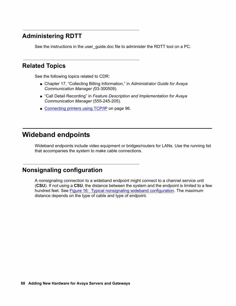
88 Adding New Hardware for Avaya Servers and Gateways
Administering RDTT See the instructions in the user_guide.doc file to administer the RDTT tool on a PC.
Related TopicsSee the following topics related to CDR:
● Chapter 17, “Collecting Billing Information,” in Administrator Guide for Avaya Communication Manager (03-300509).
● “Call Detail Recording” in Feature Description and Implementation for Avaya Communication Manager (555-245-205).
● Connecting printers using TCP/IP on page 96.
Wideband endpointsWideband endpoints include video equipment or bridges/routers for LANs. Use the running list that accompanies the system to make cable connections.
Nonsignaling configurationA nonsignaling connection to a wideband endpoint might connect to a channel service unit (CSU). If not using a CSU, the distance between the system and the endpoint is limited to a few hundred feet. See Figure 16: Typical nonsignaling wideband configuration. The maximum distance depends on the type of cable and type of endpoint.
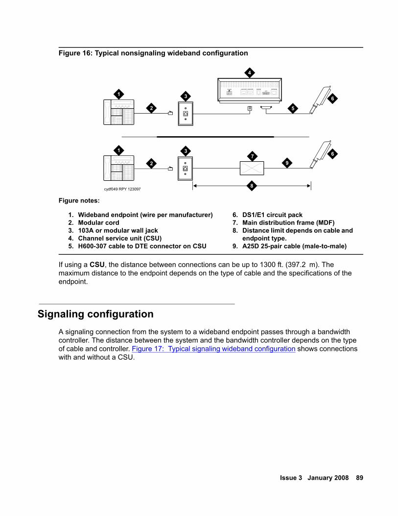
Issue 3 January 2008 89
Figure 16: Typical nonsignaling wideband configuration
If using a CSU, the distance between connections can be up to 1300 ft. (397.2 m). The maximum distance to the endpoint depends on the type of cable and the specifications of the endpoint.
Signaling configuration A signaling connection from the system to a wideband endpoint passes through a bandwidth controller. The distance between the system and the bandwidth controller depends on the type of cable and controller. Figure 17: Typical signaling wideband configuration shows connections with and without a CSU.
Figure notes:
1. Wideband endpoint (wire per manufacturer)2. Modular cord3. 103A or modular wall jack4. Channel service unit (CSU)5. H600-307 cable to DTE connector on CSU
6. DS1/E1 circuit pack 7. Main distribution frame (MDF)8. Distance limit depends on cable and
endpoint type. 9. A25D 25-pair cable (male-to-male)
cydf049 RPY 123097
AUX PORT COM PORT MODEMDTE
NETWORKPOWER
1
1
2
2
3
3
4
5
6
67
8
9
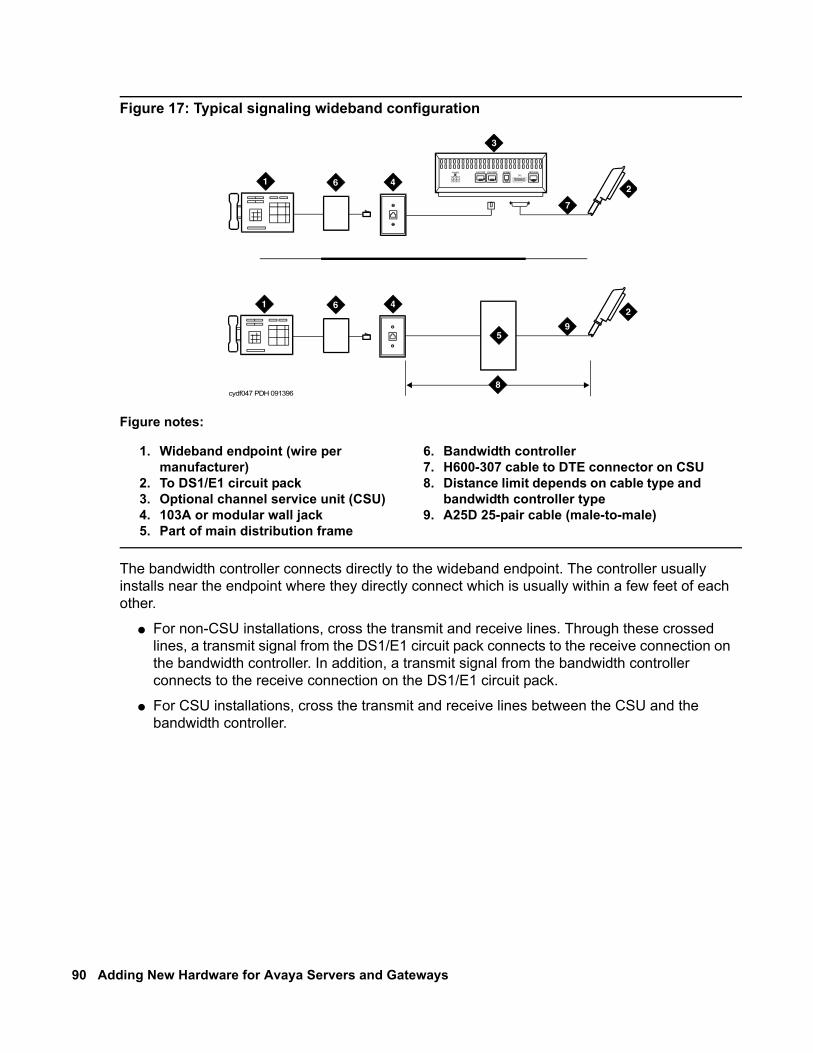
90 Adding New Hardware for Avaya Servers and Gateways
Figure 17: Typical signaling wideband configuration
The bandwidth controller connects directly to the wideband endpoint. The controller usually installs near the endpoint where they directly connect which is usually within a few feet of each other.
● For non-CSU installations, cross the transmit and receive lines. Through these crossed lines, a transmit signal from the DS1/E1 circuit pack connects to the receive connection on the bandwidth controller. In addition, a transmit signal from the bandwidth controller connects to the receive connection on the DS1/E1 circuit pack.
● For CSU installations, cross the transmit and receive lines between the CSU and the bandwidth controller.
Figure notes:
1. Wideband endpoint (wire per manufacturer)
2. To DS1/E1 circuit pack3. Optional channel service unit (CSU)4. 103A or modular wall jack5. Part of main distribution frame
6. Bandwidth controller7. H600-307 cable to DTE connector on CSU8. Distance limit depends on cable type and
bandwidth controller type9. A25D 25-pair cable (male-to-male)
AUXPORT COM PORT MODEMDTE
NETWORKPOWER
cydf047 PDH 091396
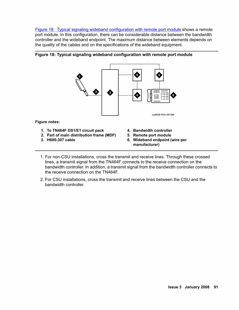
Issue 3 January 2008 91
Figure 18: Typical signaling wideband configuration with remote port module shows a remote port module. In this configuration, there can be considerable distance between the bandwidth controller and the wideband endpoint. The maximum distance between elements depends on the quality of the cables and on the specifications of the wideband equipment.
Figure 18: Typical signaling wideband configuration with remote port module
1. For non-CSU installations, cross the transmit and receive lines. Through these crossed lines, a transmit signal from the TN464F connects to the receive connection on the bandwidth controller. In addition, a transmit signal from the bandwidth controller connects to the receive connection on the TN464F.
2. For CSU installations, cross the transmit and receive lines between the CSU and the bandwidth controller.
Figure notes:
1. To TN464F DS1/E1 circuit pack2. Part of main distribution frame (MDF)3. H600-307 cable
4. Bandwidth controller5. Remote port module6. Wideband endpoint (wire per
manufacturer)
cydf048 PDH 091396
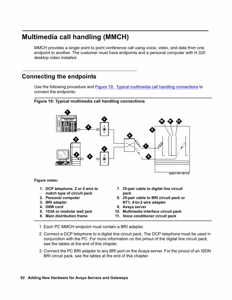
92 Adding New Hardware for Avaya Servers and Gateways
Multimedia call handling (MMCH) MMCH provides a single point to point conference call using voice, video, and data from one endpoint to another. The customer must have endpoints and a personal computer with H.320 desktop video installed.
Connecting the endpointsUse the following procedure and Figure 19: Typical multimedia call handling connections to connect the endpoints:
Figure 19: Typical multimedia call handling connections
1. Each PC MMCH endpoint must contain a BRI adapter.
2. Connect a DCP telephone to a digital line circuit pack. The DCP telephone must be used in conjunction with the PC. For more information on the pinout of the digital line circuit pack, see the tables at the end of this chapter.
3. Connect the PC BRI adapter to any BRI port on the Avaya server. For the pinout of an ISDN BRI circuit pack, see the tables at the end of this chapter.
Figure notes:
1. DCP telephone, 2 or 4 wire to match type of circuit pack
2. Personal computer3. BRI adapter4. D8W cord5. 103A or modular wall jack6. Main distribution frame
7. 25-pair cable to digital line circuit pack
8. 25-pair cable to BRI circuit pack or NT1, 4-to-2 wire adapter
9. Avaya server10. Multimedia interface circuit pack11. Voice conditioner circuit pack
Issue 3 January 2008 93
Administering the system
To administer the system:
1. Call INADS and notify the representative that the Multimedia Call Handling (MMCH)? field on page 2 of the System-Parameters Customer-Options screen must be changed to y.
2. Logoff the terminal and then log back on the terminal to see your changes.
Administering the endpoints
To administer the endpoints:
1. Log in and type add data-next <or a valid extension number>.
2. The system displays the Data Module screen. On page 1:
● In the Data Extension: field, type xxxx.
● In the Type: field, type 7500.
● In the Name: field, type the user name, such as ProShare.
● In Multimedia? field, type y.
3. On page 2:
● In the XID? field, type n.
● In the MIM Support? field, type n and press Enter.
Administering one number complex
To administer the one number complex:
1. Identify the voice telephone (DCP set) to associate with the data endpoint. The station record for this voice station must be changed.
2. Type change station station number and press Enter.3. On screen 1, in the MM Complex Data Ext: field, type the data extension number.
4. On screen 2, in the H.320 Conversion? field, type y and press Enter.5. In the Multimedia Early Answer field, type y and press Enter.
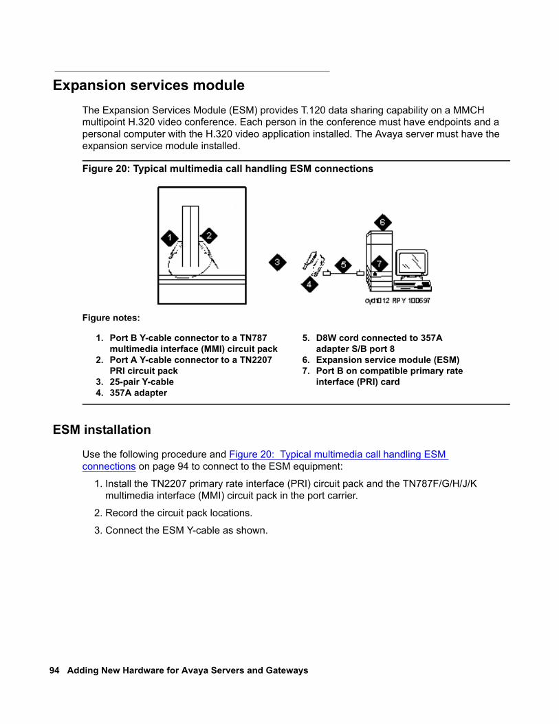
94 Adding New Hardware for Avaya Servers and Gateways
Expansion services moduleThe Expansion Services Module (ESM) provides T.120 data sharing capability on a MMCH multipoint H.320 video conference. Each person in the conference must have endpoints and a personal computer with the H.320 video application installed. The Avaya server must have the expansion service module installed.
Figure 20: Typical multimedia call handling ESM connections
ESM installation
Use the following procedure and Figure 20: Typical multimedia call handling ESM connections on page 94 to connect to the ESM equipment:
1. Install the TN2207 primary rate interface (PRI) circuit pack and the TN787F/G/H/J/K multimedia interface (MMI) circuit pack in the port carrier.
2. Record the circuit pack locations.
3. Connect the ESM Y-cable as shown.
Figure notes:
1. Port B Y-cable connector to a TN787 multimedia interface (MMI) circuit pack
2. Port A Y-cable connector to a TN2207 PRI circuit pack
3. 25-pair Y-cable4. 357A adapter
5. D8W cord connected to 357A adapter S/B port 8
6. Expansion service module (ESM)7. Port B on compatible primary rate
interface (PRI) card
Issue 3 January 2008 95
Administration To administer the DS1 circuit packs:
1. Type list configuration all and press Enter. The system displays a list of the installed carriers, circuit packs, and ports.
2. Record the board number location of the new circuit packs and verify that all other required circuit packs are present. For more information on this procedure, see ESM installation on page 94.
3. Type add DS1 xxxxx where xxxxx is the location of the TN2207 PRI circuit pack recorded in step 2 and press Enter. The system displays the DS1 circuit pack administration form.
4. Set the Name: field to ESM DS1.
5. Set the Bit Rate: field to 2.048.
6. Set the Line Coding: field to hdb3.
7. Set the Signaling Mode: field to isdn-pri.8. Set the Connect: field to pbx.
9. Set the Interface: field to network.
10. Set the Country Protocol:field to 1.
11. Set the Protocol Version:field to a.
12. Set the CRC?:field to y.
13. The Idle Code default is 11111111.
14. The DCP/Analog Bearer Capability default is 3.1 kHz.
15. Set the MMI Cabling Board: field to xxxxx where xxxxx is the location of the TN787F/H/J/K MMI circuit pack recorded in step 2. This location must be the slot for port B of the Y-cable.
The system displays the MMI Interface: field ESM.
16. Type add signaling-group next.
The system displays the signaling-group form.
17. Change Associated Signaling: field to y.
18. Change Primary D-Channel Port: field to xxxx17 where xxxx is the address of the TN2207 PRI circuit pack. An example address is B0517.
19. The Max Number of NCA TSC: default is 0.
20. The Max Number of GA TSC: default is 0.
21. Trunk Group for NCA TSC: ____ (leave blank).
96 Adding New Hardware for Avaya Servers and Gateways
22. Trunk Group for Channel Selection:____ (leave blank).
23. Log off the terminal and then log back on the terminal to view your changes.
Place test callPlace multimedia data-conference call to an endpoint with known video capability to test the esm function.
TroubleshootingTo determine ESM link status type the following commands from the system administration terminal:
● Status esm
● Status signaling-group
● List MMI
Note:Note: When you move ESM circuit packs, you must remove the DS1 and signaling
group translations. You cannot use the change circuit pack command.
For more information, see Expansion services module on page 94.
PrintersThis section provides information on connecting and configuring printers that work with your system and Avaya Communication Manager.
Connecting printers using TCP/IPYou can connect printers to the switch using asynchronous TCP/IP links and a terminal server. This section provides information on connecting adjuncts to the C-LAN circuit pack in a media gateway. This section also provides the initial administration for these connections. For connecting a printer to a G700 or G350 Media Gateway, see Terminal server installation on page 71 for more information.
Issue 3 January 2008 97
Task list
Whether you use an end-to-end TCP/IP configuration, a terminal server or a PC running RSP, you must complete the following tasks:
● Administering IP node names on page 83.● Administering IP services on page 83.● Administering adjunct parameters on page 97.● If you are using a terminal server, also complete Installing and administering the terminal
server on page 72.● If you are using a PC with the Downloadable RSP Tool, complete Using the downloadable
reliable session-layer protocol (RSP) tool on page 98.
Administering adjunct parametersYou must administer adjunct parameters to let the system know that the adjunct is connected through TCP/IP.
PMS journal and PMS log printersSee Guestworks and DEFINITY Systems Technician Handbook for Hospitality Installations (555-231-743).
System printer1. Type change system-parameters features and press Enter.
The system displays the Feature-Related System Parameters screen.2. Move to Page 4.3. In the System Printer Endpoint field, type SYS_PRNT.4. Press Enter to save your changes.
Testing the switch-to-adjunct link You can use the test, status, busyout and release commands to find and correct problems with a system printer, PMS log printer, or PMS journal printer. For more information about these commands, see the Maintenance manual for your switch.
If a link does not come up immediately, try using the busyout and release commands. The busyout commands are journal-link pms-log and wakeup-log, and sp-link. The release commands are journal-link pms-log and wakeup-log, and sp-link.
Note:Note: Status sp-link can show a system printer link as down, when it is actually properly
connected. If no data is being transmitted, the switch might not see this link as active.
98 Adding New Hardware for Avaya Servers and Gateways
Using the downloadable reliable session-layer protocol (RSP) tool
The intent of the Reliable Session-Layer Protocol (RSP) is to guarantee delivery of data records from the switch. The protocol delivers the records to an output device that connects to the switch over an asynchronous TCP/IP link. With the Downloadable RDTT tool, you can implement this protocol on a PC that collects data records in a file. The protocol ensures that the data records arrive safely at the PC. You can then send the output file to a printer. For more information, see Reliable Data Transport Tool (RDTT) Package on page 86.
DS1/T1 CPE loopback jackThis section provides information on how to install and use a DS1 loopback jack. You can use the jack to test the DS1 span between the Avaya server or gateway and the network interface point. The loopback jack is required when DC power is at the interface to the integrated channel service unit (ICSU).
Note:Note: Do not remove the loopback jack after installation. The jack must always be
available for remote tests of the DS1 span.
Note:Note: For G700 or G350 Media Gateway systems, the channel service unit (CSU) is
integrated within the MM710 board. This means that there is no need for a separate external device. For earlier media gateway systems, the integrated channel service unit (ICSU), also known as the 120A2, is a separate device. The ICSU plugs into the back of the media gateway.
Note:Note: For G700 or G350 Media Gateway systems, the loopback jack isolates the
MM710 internal CSU from the DC power and properly loops the DC span power.
Issue 3 January 2008 99
Installing a loopback jack You can install a loopback jack with or without a smart jack.
With a smart jack
Install the loopback jack at the interface to the smart jack, if possible. This position provides maximum coverage of CPE wiring when remote loopback tests are run. The installation method depends on whether the smart jack is accessible and whether there is an extended demarcation point. The following installation scenarios are possible.
● If the smart jack is not accessible, install the loopback jack at the extended demarcation point.
● If there is no extended demarcation point, install the loopback jack directly at the network interface point. An example of this installation is in Figure 21: Network interface at smart jack for a 120A2 (or later) ICSU on page 109.
● If there is an extended demarcation point and the smart jack is not accessible, install the loopback jack as shown in Figure 22: Network interface at extended demarcation point (smart jack inaccessible) for a 120A2 (or later) ICSU on page 110.
● If there is an extended demarcation point, but the smart jack is accessible, install the loopback jack as shown in Figure 23: Network interface at extended demarcation point (smart jack accessible) for a 120A2 (or later) ICSU on page 111.
To install the loopback jack:
1. Disconnect the RJ-48 (8-wide) connector at the appropriate interface point and connect the loopback jack in series with the DS1 span. For examples, see Figure 21: Network interface at smart jack for a 120A2 (or later) ICSU on page 109 through Figure 25: Network interface at “dumb” block with repeater line to fiber MUX for a 120A2 (or later) ICSU on page 113.
2. Plug the H600-383 cable from the ICSU or the MM710 into the female connector on the loopback jack.
3. Plug the male connector on the loopback jack cable into the network interface point.
Note:Note: Do not remove the loopback jack after installation. The jack is not a test tool and
must always be available to remotely test a DS1 span.
100 Adding New Hardware for Avaya Servers and Gateways
Without a smart jack
Install the loopback jack at the point where the cable connections from the ICSU plugs into the dumb block. If there is more than one dumb block, choose the one that is closest to the Interface Termination feed or the fiber MUX. This choice provides maximum coverage for loopback jack tests. See Figure 24: Network interface at “dumb” block for a 120A2 (or later) ICSU on page 112 and Figure 25: Network interface at “dumb” block with repeater line to fiber MUX for a 120A2 (or later) ICSU on page 113.
To install the loopback jack:
1. Disconnect the RJ-48 (8-wide) connector at the appropriate interface point and connect the loopback jack in series with the DS1 span. For examples, see Figure 21: Network interface at smart jack for a 120A2 (or later) ICSU on page 109 through Figure 25: Network interface at “dumb” block with repeater line to fiber MUX for a 120A2 (or later) ICSU on page 113.
2. Plug the H600-383 cable from the ICSU, or from the MM710, into the female connector on the loopback jack.
3. Plug the male connector on the loopback jack cable into the network interface point.
Note:Note: Do not remove the loopback jack after installation. The jack is not a test tool and
must always be available to remotely test a DS1 span.
Administering the loopback jack To administer the loopback jack:
1. At the management terminal, type change ds1 location where location is the DS1 interface circuit pack that corresponds to the loopback jack. Press Enter,
2. Verify that the near-end CSU type is set to integrated.
3. Page down to Page 2 of the screen. Change the supply CPE loopback jack power field to y.
Setting this field to y informs the technician that a loopback jack is present on the facility. The technician can determine whether the facility is available for remote testing.
4. Type save translation and press Enter to save the new information.
Issue 3 January 2008 101
Loopback testing with a smart jackThe loopback jack and smart jack isolate faults by dividing the DS1 span into three sections. For more information, see Figure 21: Network interface at smart jack for a 120A2 (or later) ICSU on page 109 through Figure 23: Network interface at extended demarcation point (smart jack accessible) for a 120A2 (or later) ICSU on page 111:
The three sections are:
● From the 120A2, or later, ICSU or from the MM710 to the loopback jack
● From the loopback jack to the smart jack, which is the network interface point
● From the smart jack to the CO
The first two sections are your responsibility. The last is the responsibility of the DS1 service provider.
Testing the DS1 span from the ICSU to the loopback jack
The DS1 span test has 2 parts.
● Checking for circuit connectivity
The first part of the test turns on power to the loopback jack. The test sends a signal from the DS1 circuit pack, through the wiring, to the loopback jack. The test allows about 10 seconds for the signal to loop around the loopback jack and return to the DS1 circuit pack. Then it sends the results to the management terminal and proceeds to the second part of the test.
● The second part of the test sends the standard, 3-in-24 DS1 stress-testing pattern from the DS1 board, through the loopback jack, and back to a bit error detector and counter on the DS1 board. A bit-error rate counter displays the results on the management terminal until you terminate the test.
Always perform both parts of the test. Proceed as follows.
Checking the integrity of local equipmentBefore you go any further, ensure that the problem is actually on the DS1 span by testing the equipment that connects to the span at the near end. Test the DS1 circuit pack, and perform any needed maintenance or repairs.
102 Adding New Hardware for Avaya Servers and Gateways
Busying out the DS1 circuit packNow take the DS1 circuit out of service.
Note:Note: If you have a G700 or G350 Media Gateway, substitute XXXVS for UUCSS in the
following command. XXX is the administered number of the G700 or G350, such as 002. VS is the slot number on the G700 or G350 of the Media Module, such as V3. The V is not a variable and must be included in the command exactly where shown. A sample address for a DS1 circuit pack on a G700 or G350 Media Gateway is 002V3.
1. Once you are sure that the DS1 circuit pack and ICSU are functioning correctly, go to the management terminal and busy out the DS1 circuit pack by typing busyout board UUCSS. UU is the cabinet number. C is the carrier letter. SS is the slot number of the DS1 board.
Administering the DS1 for the test1. At the management terminal, open the DS1 Administration screen. Type change ds1 UUCSS, where UU is the cabinet number, C is the carrier letter, and SS is the slot number of the DS1 board.
2. Ensure that the near-end csu type field is set to integrated.
3. Change to page 2 of the DS1 administration screen, and confirm that the value of the TX LBO field is 0dB.
4. If the value of the TX LBO field is not 0dB, record the current value. Then set the TX LBO field to 0dB for testing.
5. Press Enter to make the changes, Cancel to quit without changes.
Testing the integrity of the loopback circuitNow perform the first part of the actual loopback test.
Note:Note: If you have a G700 or G350 Media Gateway, substitute XXXVS for UUCSS in the
following command. XXX is the administered number of the G700 or G350, such as 002. VS is the slot number on the G700 or G350 of the Media Module, such as V3. The V is not a variable and needs to be included in the command exactly where shown. A sample address for a DS1 circuit pack on a G700 or G350 Media Gateway might look like this: 002V3.
1. At the management terminal, type test ds1-loop UUCSS cpe-loopback-jack. UU is the cabinet number. C is the carrier letter. SS is the slot number of the DS1 board.
The loopback jack turns on. Active, DS1 facility alarms (if any) clear. After about 20 seconds, the first set of results appears on the terminal.
Issue 3 January 2008 103
2. If FAIL appears on the terminal display, there might be a fault in the wiring between the ICSU and the loopback jack. Or, the loopback jack might be faulty. Isolate the problem by replacing the loopback jack and repeating step 1.
3. If FAIL still appears after you replaced the loopback jack, suspect a wiring problem. Replace the cable between the ICSU and the loopback jack. Then repeat step 1.
4. When PASS appears on the terminal, proceed with the second part of the test, checking the integrity of transmitted data.
Testing the integrity of data sent over the loopNow perform the second part of the test, checking for data errors.
Note:Note: The loss of signal (LOS) alarm in demand test #138 is not processed during this
test while the 3-in-24 pattern is active.
Clearing the results of previous tests
Note:Note: If you have a G700 or G350 Media Gateway, substitute XXXVS for UUCSS in the
following commands. XXX is the administered number of the G700 or G350, such as 002. VS is the slot number on the G700 or G350 of the Media Module, such as V3. The V is not a variable and needs to be included in the command exactly where shown. A sample address for a DS1 circuit pack on a G700 or G350 Media Gateway is 002V3.
1. Zero out the bit-error counter. At the management terminal, type clear meas ds1 loop UUCSS. UU is the cabinet number. C is the carrier letter. SS is the slot number of the DS1 board.
2. Zero out the performance measurement counter. At the management terminal, type clear meas ds1 log UUCSS. UU is the cabinet number. C is the carrier letter. SS is the slot number of the DS1 board.
3. Zero out the ESF error count. At the management terminal, type clear meas ds1 esf UUCSS. UU is the cabinet number. C is the carrier letter. SS is the slot number of the DS1 board.
Running the data test
Note:Note: If you have a G700 or G350 Media Gateway, substitute XXXVS for UUCSS in the
following command. XXX is the administered number of the G700 or G350, such as 002. VS is the slot number on the G700 or G350 of the Media Module, such as V3. The V is not a variable and needs to be included in the command exactly where shown. A sample address for a DS1 circuit pack on a G700 or G350 Media Gateway is 002V3.
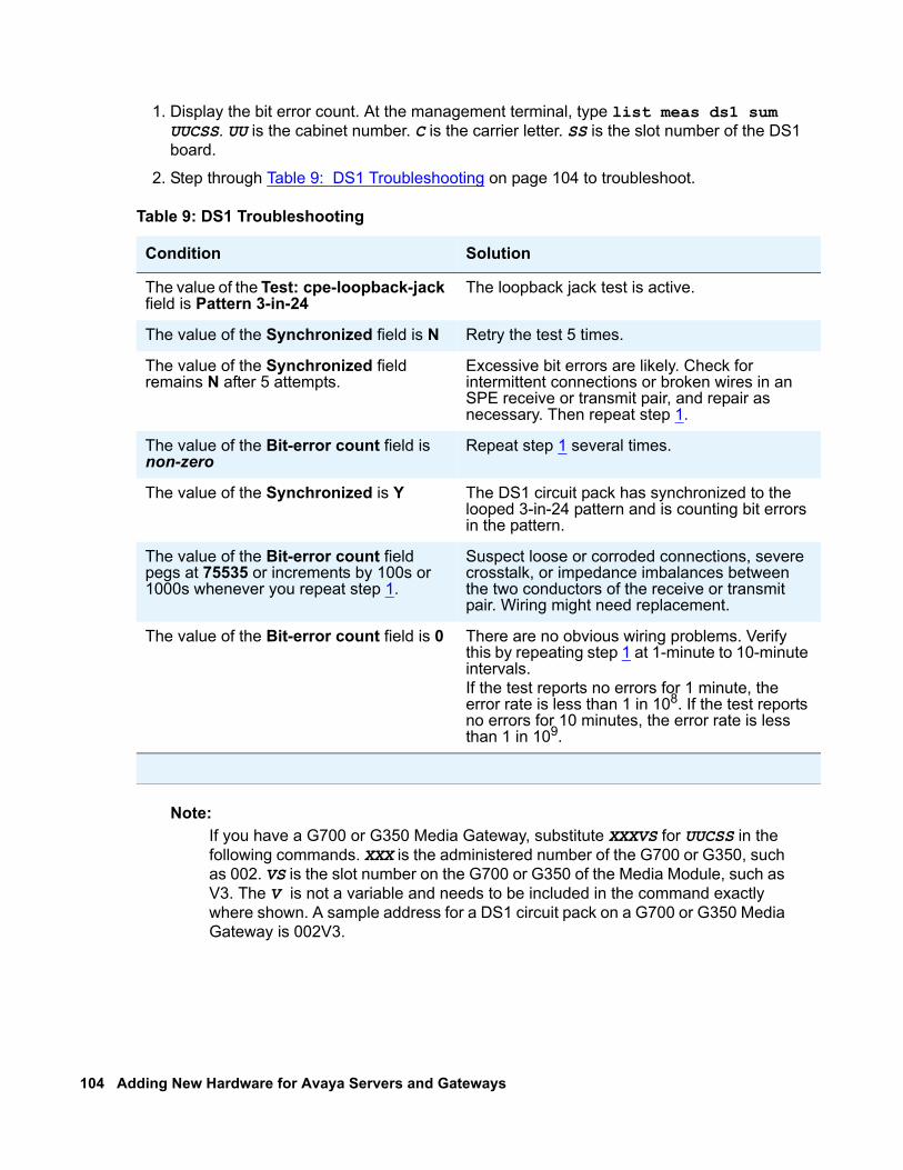
104 Adding New Hardware for Avaya Servers and Gateways
1. Display the bit error count. At the management terminal, type list meas ds1 sum UUCSS. UU is the cabinet number. C is the carrier letter. SS is the slot number of the DS1 board.
2. Step through Table 9: DS1 Troubleshooting on page 104 to troubleshoot.
Note:Note: If you have a G700 or G350 Media Gateway, substitute XXXVS for UUCSS in the
following commands. XXX is the administered number of the G700 or G350, such as 002. VS is the slot number on the G700 or G350 of the Media Module, such as V3. The V is not a variable and needs to be included in the command exactly where shown. A sample address for a DS1 circuit pack on a G700 or G350 Media Gateway is 002V3.
Table 9: DS1 Troubleshooting
Condition Solution
The value of the Test: cpe-loopback-jack field is Pattern 3-in-24
The loopback jack test is active.
The value of the Synchronized field is N Retry the test 5 times.
The value of the Synchronized field remains N after 5 attempts.
Excessive bit errors are likely. Check for intermittent connections or broken wires in an SPE receive or transmit pair, and repair as necessary. Then repeat step 1.
The value of the Bit-error count field is non-zero
Repeat step 1 several times.
The value of the Synchronized is Y The DS1 circuit pack has synchronized to the looped 3-in-24 pattern and is counting bit errors in the pattern.
The value of the Bit-error count field pegs at 75535 or increments by 100s or 1000s whenever you repeat step 1.
Suspect loose or corroded connections, severe crosstalk, or impedance imbalances between the two conductors of the receive or transmit pair. Wiring might need replacement.
The value of the Bit-error count field is 0 There are no obvious wiring problems. Verify this by repeating step 1 at 1-minute to 10-minute intervals.If the test reports no errors for 1 minute, the error rate is less than 1 in 108. If the test reports no errors for 10 minutes, the error rate is less than 1 in 109.
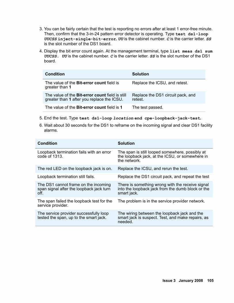
Issue 3 January 2008 105
3. You can be fairly certain that the test is reporting no errors after at least 1 error-free minute. Then, confirm that the 3-in-24 pattern error detector is operating. Type test ds1-loop UUCSS inject-single-bit-error. UU is the cabinet number. C is the carrier letter. SS is the slot number of the DS1 board.
4. Display the bit error count again. At the management terminal, type list meas ds1 sum UUCSS. UU is the cabinet number. C is the carrier letter. SS is the slot number of the DS1 board.
5. End the test. Type test ds1-loop location end cpe-loopback-jack-test.6. Wait about 30 seconds for the DS1 to reframe on the incoming signal and clear DS1 facility
alarms.
Condition Solution
The value of the Bit-error count field is greater than 1
Replace the ICSU, and retest.
The value of the Bit-error count field is still greater than 1 after you replace the ICSU.
Replace the DS1 circuit pack, and retest.
The value of the Bit-error count field is 1 The test passed.
Condition Solution
Loopback termination fails with an error code of 1313.
The span is still looped somewhere, possibly at the loopback jack, at the ICSU, or somewhere in the network.
The red LED on the loopback jack is on. Replace the ICSU, and rerun the test.
Loopback termination still fails. Replace the DS1 circuit pack, and repeat the test
The DS1 cannot frame on the incoming span signal after the loopback jack turn off.
There is something wrong with the receive signal into the loopback jack from the dumb block or the smart jack.
The span failed the loopback test for the service provider.
The problem is in the service provider network.
The service provider successfully loop tested the span, up to the smart jack.
The wiring between the loopback jack and the smart jack is suspect. Test, and make repairs, as needed.
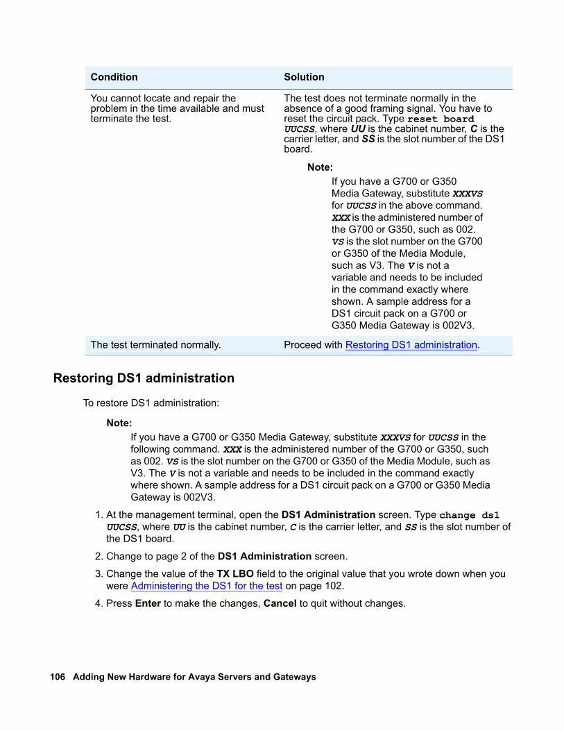
106 Adding New Hardware for Avaya Servers and Gateways
Restoring DS1 administration
To restore DS1 administration:
Note:Note: If you have a G700 or G350 Media Gateway, substitute XXXVS for UUCSS in the
following command. XXX is the administered number of the G700 or G350, such as 002. VS is the slot number on the G700 or G350 of the Media Module, such as V3. The V is not a variable and needs to be included in the command exactly where shown. A sample address for a DS1 circuit pack on a G700 or G350 Media Gateway is 002V3.
1. At the management terminal, open the DS1 Administration screen. Type change ds1 UUCSS, where UU is the cabinet number, C is the carrier letter, and SS is the slot number of the DS1 board.
2. Change to page 2 of the DS1 Administration screen.
3. Change the value of the TX LBO field to the original value that you wrote down when you were Administering the DS1 for the test on page 102.
4. Press Enter to make the changes, Cancel to quit without changes.
You cannot locate and repair the problem in the time available and must terminate the test.
The test does not terminate normally in the absence of a good framing signal. You have to reset the circuit pack. Type reset board UUCSS, where UU is the cabinet number, C is the carrier letter, and SS is the slot number of the DS1 board.
Note:Note: If you have a G700 or G350
Media Gateway, substitute XXXVS for UUCSS in the above command. XXX is the administered number of the G700 or G350, such as 002. VS is the slot number on the G700 or G350 of the Media Module, such as V3. The V is not a variable and needs to be included in the command exactly where shown. A sample address for a DS1 circuit pack on a G700 or G350 Media Gateway is 002V3.
The test terminated normally. Proceed with Restoring DS1 administration.
Condition Solution
Issue 3 January 2008 107
Releasing the DS1 circuit pack
To release the DS1 circuit pack:
Note:Note: If you have a G700 or G350 Media Gateway, substitute XXXVS for UUCSS in the
following command. XXX is the administered number of the G700 or G350, such as 002. VS is the slot number on the G700 or G350 of the Media Module, such as V3. The V is not a variable and needs to be included in the command exactly where shown. A sample address for a DS1 circuit pack on a G700 or G350 Media Gateway is 002V3.
1. Release the DS1 circuit pack. From the management terminal, type release board UUCSS. UU is the cabinet number. C is the carrier letter. SS is the slot number of the DS1 board.
2. Leave the loopback jack in place.
Testing the DS1 span from the smart jack to the network interfacetermination or fiber multiplexer (MUX)
To test the DS1 span:
1. Have the service provider run a smart-jack loopback test against the network interface wiring that links the smart jack to the CO. For more information, see section 3 in Figure 21: Network interface at smart jack for a 120A2 (or later) ICSU on page 109 through Figure 23: Network interface at extended demarcation point (smart jack accessible) for a 120A2 (or later) ICSU on page 111.
2. If the tests fails, there is a problem on the network side. Have the service provider correct it.
108 Adding New Hardware for Avaya Servers and Gateways
Testing the DS1 span from the loopback jack to the smart jack
Test the short length of customer premises wiring between the loopback jack and the smart jack. Use a loopback that overlaps this section of the span. For more information, see section 2 in the following 3 figures.
● Have the DS1 service provider at the CO end run a local ICSU line loopback test.
● Have the DS1 service provider at the CO end run a local DS1 payload loopback test.
● Run a far-end ICSU or MM710 line loopback, using the following procedure.
Note:Note: This test cannot isolate the problem if there are problems in the wiring between
the far-end CO and the far-end ICSU. You must coordinate this test with the DS1 service provider.
Note:Note: If you have a G700 or G350 Media Gateway, substitute XXXVS for UUCSS in the
following command. XXX is the administered number of the G700 or G350, such as 002. VS is the slot number on the G700 or G350 of the Media Module, such as V3. The V is not a variable and needs to be included in the command exactly where shown. A sample address for a DS1 circuit pack on a G700 or G350 Media Gateway is 002V3.
1. From the management terminal, type test ds1-loop location far-csu-loopback-test-begin, where location is the cabinet and slot location of the DS1 board (for example, 02205) or the administered and slot number of the G700. The V is not a variable and needs to be included in the command exactly where shown. A sample address for a DS1 circuit pack on a G700 or G350 Media Gateway might look like this: 002V3.
2. Examine the bit-error counts, as in Testing the integrity of data sent over the loop on page 103.
3. Terminate the test. Type test ds1-loop location end-loopback/span-test.
4. If the tests fails and no problems develop when you follow the procedures in Testing the DS1 span from the ICSU to the loopback jack on page 101 or Testing the DS1 span from the smart jack to the network interface termination or fiber multiplexer (MUX) on page 107, there is a problem between the loopback jack to the smart jack. Work with the service provider to isolate the fault.
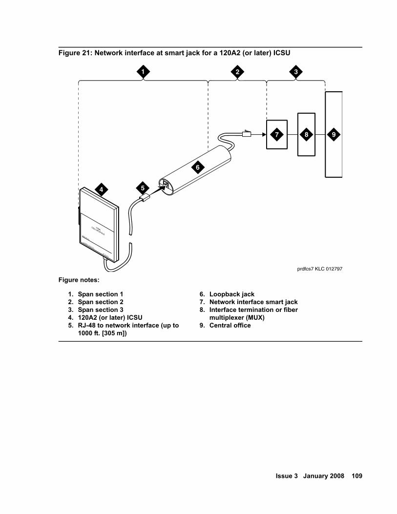
Issue 3 January 2008 109
Figure 21: Network interface at smart jack for a 120A2 (or later) ICSU
Figure notes:
1. Span section 12. Span section 23. Span section 34. 120A2 (or later) ICSU5. RJ-48 to network interface (up to
1000 ft. [305 m])
6. Loopback jack7. Network interface smart jack8. Interface termination or fiber
multiplexer (MUX)9. Central office
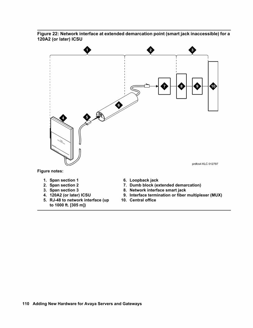
110 Adding New Hardware for Avaya Servers and Gateways
Figure 22: Network interface at extended demarcation point (smart jack inaccessible) for a 120A2 (or later) ICSU
Figure notes:
1. Span section 12. Span section 23. Span section 34. 120A2 (or later) ICSU5. RJ-48 to network interface (up
to 1000 ft. [305 m])
6. Loopback jack7. Dumb block (extended demarcation)8. Network interface smart jack9. Interface termination or fiber multiplexer (MUX)
10. Central office
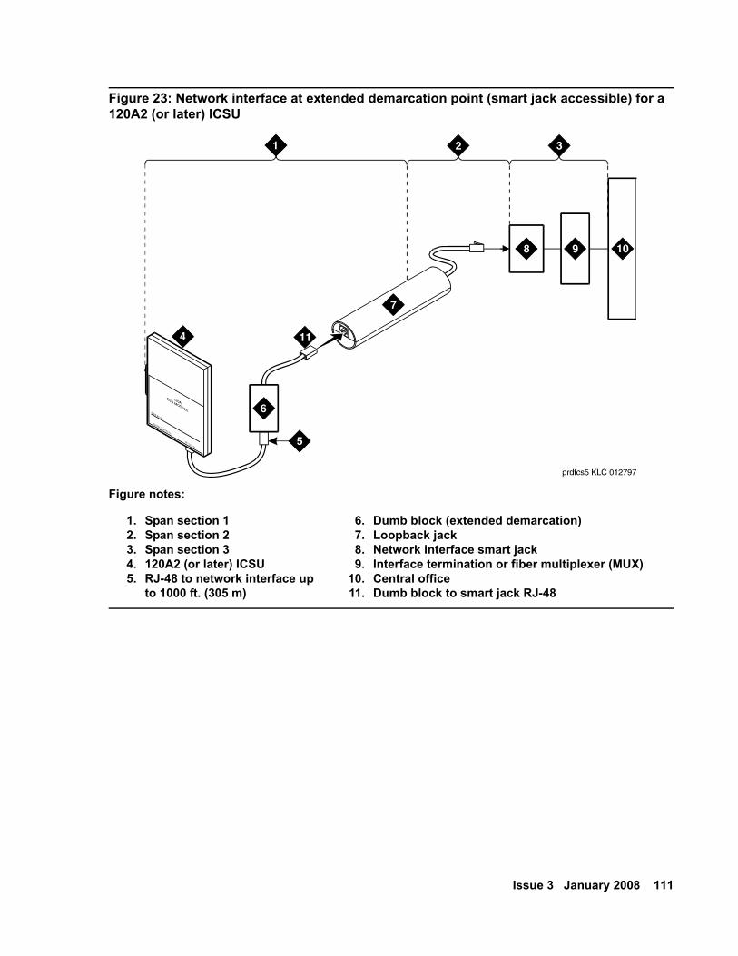
Issue 3 January 2008 111
Figure 23: Network interface at extended demarcation point (smart jack accessible) for a 120A2 (or later) ICSU
Figure notes:
1. Span section 12. Span section 23. Span section 34. 120A2 (or later) ICSU5. RJ-48 to network interface up
to 1000 ft. (305 m)
6. Dumb block (extended demarcation)7. Loopback jack8. Network interface smart jack9. Interface termination or fiber multiplexer (MUX)
10. Central office11. Dumb block to smart jack RJ-48
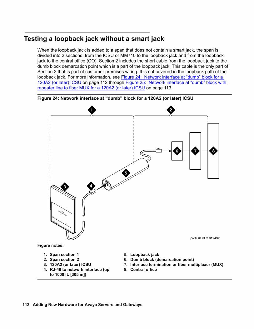
112 Adding New Hardware for Avaya Servers and Gateways
Testing a loopback jack without a smart jackWhen the loopback jack is added to a span that does not contain a smart jack, the span is divided into 2 sections: from the ICSU or MM710 to the loopback jack and from the loopback jack to the central office (CO). Section 2 includes the short cable from the loopback jack to the dumb block demarcation point which is a part of the loopback jack. This cable is the only part of Section 2 that is part of customer premises wiring. It is not covered in the loopback path of the loopback jack. For more information, see Figure 24: Network interface at “dumb” block for a 120A2 (or later) ICSU on page 112 through Figure 25: Network interface at “dumb” block with repeater line to fiber MUX for a 120A2 (or later) ICSU on page 113.
Figure 24: Network interface at “dumb” block for a 120A2 (or later) ICSU
Figure notes:
1. Span section 12. Span section 23. 120A2 (or later) ICSU4. RJ-48 to network interface (up
to 1000 ft. [305 m])
5. Loopback jack6. Dumb block (demarcation point)7. Interface termination or fiber multiplexer (MUX)8. Central office
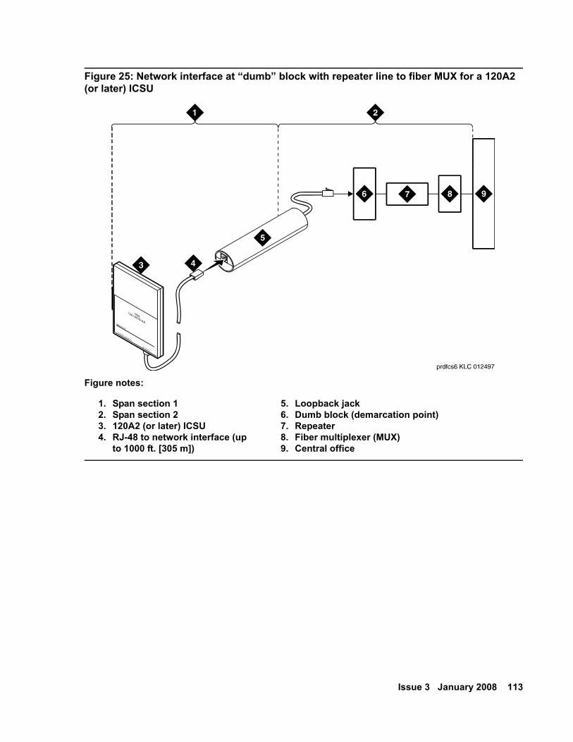
Issue 3 January 2008 113
Figure 25: Network interface at “dumb” block with repeater line to fiber MUX for a 120A2 (or later) ICSU
Figure notes:
1. Span section 12. Span section 23. 120A2 (or later) ICSU4. RJ-48 to network interface (up
to 1000 ft. [305 m])
5. Loopback jack6. Dumb block (demarcation point)7. Repeater8. Fiber multiplexer (MUX)9. Central office
114 Adding New Hardware for Avaya Servers and Gateways
You are responsible for finding and correcting problems in the customer wiring (section 1 and the loopback cable portion of section 2). The DS1 service provider is responsible for finding and correcting problems in the majority of section 2.
Proceed as follows.
1. Test customer premises wiring from the ICSU to the loopback jack, as described in the “DS1 Span Test” section.
2. Test the loopback jack-to-dumb block and dumb block-to-CO wiring. For more information, see section 2 in Figure 24: Network interface at “dumb” block for a 120A2 (or later) ICSU on page 112 through Figure 25: Network interface at “dumb” block with repeater line to fiber MUX for a 120A2 (or later) ICSU on page 113). This test can be done using a loopback that “overlaps” the section of the span. Use any of the following loopbacks:
● The line loopback of the local ICSU. The DS1 service provider at the CO end typically activates, tests, and then deactivates this loopback.
● The payload loopback. of the local DS1 interface. The DS1 service provider at the CO end activates and tests this loopback.
● The line loopback of the far-end ICSU or MM710. Activate this test at the management terminal by typing test ds1-loop location far-csu-loopback-test-begin, where location is the DS1 interface circuit pack corresponding to the loopback jack. To terminate this test, type test ds1-loop location end-loopback/span-test, where location is the DS1 interface circuit pack corresponding to the loopback jack.
Bit error counts are examined as described in the “DS1 Span Test” section. This test only isolates problems to Section 2 wiring if there are no problems in the wiring between the far-end CO and the far-end ICSU. Coordinate this test with the DS1 service provider.
Failure of any of the previous tests indicate a problem in Section 2. This problem could be bad loopback jack -to-”dumb” block cabling. However, it more likely indicates a problem somewhere between the “dumb” block and the CO. This problem is the responsibility of the DS1 service provider.
If the DS1 Span Test confirms that there are no problems in Section 1, proceed as follows to avoid unnecessary dispatch.
a. Identify and contact the DS1 service provider.
b. Inform the DS1 provider that loopback tests of the CPE wiring to the “dumb” block (section 1) showed no problems.
c. If the far-end ICSU or MM710 line loopback test failed, inform the DS1 provider.
d. Request that the DS1 provider perform a loopback test of their portion of the Section 2 wiring. The DS1 provider must send someone out to loop Section 2 back to the CO at the “dumb” block.
If this test fails, the problem is in the service provider wiring.
If the test passes, the problem is in the cable between the loopback jack and the “dumb” block. Replace the loopback jack.
Issue 3 January 2008 115
Configurations using fiber multiplexersUse the loopback jack when the customer premises DS1 wiring:
● connects to an on-site fiber multiplexer (MUX)
and
● allows remote tests of the wiring to the network interface point on the MUX. This requires that the MM710 CSU be set so it can be used on DS1 wiring to the MUX.
Fiber MUXs can take the place of Interface termination feeds as shown in Figure 21: Network interface at smart jack for a 120A2 (or later) ICSU on page 109 through Figure 24: Network interface at “dumb” block for a 120A2 (or later) ICSU on page 112 Test these spans with the same procedures as metallic spans. Note the following points:
1. Fiber MUXs might have loopback capabilities that the service provider can activate from the CO end. These capabilities might loop the signal back to the CO or back to the DS1 circuit pack or MM710. If the MUX provides the equivalent of a line loopback on the “problem” DS1 facility, activate the MUX after a successful loopback jack test. Then use the MUX to isolate problems to the wiring between the loopback jack and the MUX.
2. Be aware that there are installations that use repeater metallic lines between the MUX and the “dumb” block. These lines require DC power for the repeaters and this DC power is present at the “dumb” block interface to the CPE equipment. A loopback jack is required in this configuration to properly isolate and terminate the DC power.
To check for the presence of DC, make the following 4 measurements at the network interface jack:
1. From transmit tip (T, Pin 5) to receive tip (T1, Pin 2)
2. From transmit ring (R, Pin 4) to receive ring (R1, Pin 1)
3. From transmit tip (T, Pin 5) to transmit ring (R, Pin 4)
4. From receive tip (T1, Pin 2) to receive ring (R1, Pin 1)
All measurements should read zero (0) volts DC. For more information about pin numbers and pin designations, see Integrated CSU Module Installation and Operation 555-230-193.
116 Adding New Hardware for Avaya Servers and Gateways
External modems The following section assumes that you are using one of the recommended external modems. However, any locally obtained, type-approved external modem will work. Contact your Avaya representative for more information.
Recommended modems include:
● for S8300 Server:
● Paradyne COMSPHERE 3810 Plus and 3811 Plus
● Paradyne COMSPHERE 3910
● for S8400, S8500, S8700-Series Servers
● Multi-Tech MT5634ZBA-USB-V92
● Multi-Tech MT5634ZBA-V92-GLOBAL
Hardware required when configuring modems To configure many modems, use the Hayes-compatible AT command set.
Note:Note: If your modem uses a USB connection, use the USB ports instead of the serial
port. Also, AT commands are not required, so you can skip this section. Use the factory defaults.
Before you can enter AT configuration commands, first connect a terminal or a PC with a keyboard, monitor, and terminal-emulation software to the modem.
Proceed as follows:
1. Connect one end of an RS-232 cable to an RS-232, serial-communications port, often called a COM port, on the terminal or PC.
2. Connect the other end of the RS-232 cable to the modem.
3. If you are using a PC, start your terminal emulation software.
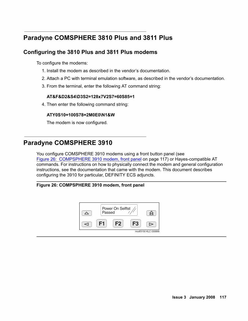
Issue 3 January 2008 117
Paradyne COMSPHERE 3810 Plus and 3811 Plus
Configuring the 3810 Plus and 3811 Plus modems
To configure the modems:
1. Install the modem as described in the vendor’s documentation.
2. Attach a PC with terminal emulation software, as described in the vendor’s documentation.
3. From the terminal, enter the following AT command string:
AT&F&D2&S4\D3S2=128x7V2S7=60S85=14. Then enter the following command string:
ATY0S10=100S78=2M0E0\N1&WThe modem is now configured.
Paradyne COMSPHERE 3910 You configure COMSPHERE 3910 modems using a front button panel (see Figure 26: COMPSPHERE 3910 modem, front panel on page 117) or Hayes-compatible AT commands. For instructions on how to physically connect the modem and general configuration instructions, see the documentation that came with the modem. This document describes configuring the 3910 for particular, DEFINITY ECS adjuncts.
Figure 26: COMPSPHERE 3910 modem, front panel
F1 F2 F3
Power On SelftstPassed
modf3150 KLC 030899
118 Adding New Hardware for Avaya Servers and Gateways
Configuring the 3910 for CMS
The COMSPHERE 3910 modem may be used as the Call Management System (CMS) Remote Console Modem or as a device that provides serial connectivity to CMS through the Network Terminal Server (NTS). For the instructions to set up the modem for use in CMS (other configurations may work as well), see one of the following:
● Avaya Call Management System (CMS) Sun Enterprise 3500 Computer Hardware Installation, Maintenance, and Troubleshooting, 585-215-873
● Avaya Call Management System (CMS) Sun Ultra 5 Computer Hardware Installation, Maintenance, and Troubleshooting, 585-215-871
Multi-Tech MT5634ZBA-USB-V92 Avaya recommends using a Multi-Tech USB modem, model MT5634ZBA-USB-V92, with any of the following configurations:
● S8300/G700
● S8500
● S8700-series
This modem is used for sending alarms, and for remote dial up to the server for maintenance and administration.
Configuring the MT5634ZBA-USB-V92 modem
In the United States, the Multi-Tech MT5634ZBA-US-V92 modem gets configured automatically through the USB port with the factory defaults. No special configuration is necessary. In a non-US country, the modem might require settings specific to the country in which the modem is used.
Multi-Tech MT5634ZBA-V92-GLOBAL Avaya recommends using a Multi-Tech USB modem, model MT5634ZBA-V92-GLOBAL, with S8400, S8500, S8700-series Servers or a G350 media gateway.
The Multi-Tech serial modem connects the remote maintenance board (RMB) to an external trunk. The RMB, which monitors S8500 components and software, can then send alarms to the services support group. Additionally, you can dial the S8500 remotely to either turn power on or off. For more information, see Installing and Configuring the Avaya S8500 Server (03-300143).
Issue 3 January 2008 119
The Multi-Tech serial modem connects the G350 media gateway to an external trunk. This connection enables remote dial in capability for administration and troubleshooting. For more information, see Installation of the Avaya G350 Media Gateway Controlled by an Avaya S8300, S8500, or S8700 Server, 555-245-104.
Note:Note: The Multi-Tech serial modem, which requires its own power, comes with a DC
adapter and a separately shipped power cord and modular cord.
Administration The Multi-Tech modems do not require administration if used in the United States. In non-US countries, these modems might require administration.
For the full range of modem options, see the Administrator Guide for Avaya Communication Manager (03-300509).
ISDN converters and adapters This section provides information on ISDN converters and adapters. These converters and adapters are sometimes necessary when connecting to coaxial facilities in either a multicarrier cabinet or a single carrier cabinet.Connections include:
● Integrated Services Data Network Primary Rate Interface (ISDN-PRI) to Direct Access Secondary Storage (DASS)
● PRI to Digital Private Network Signaling System (DPNSS)● PRI to ISDN Basic Rate Interface (ISDN-BRI)
Converter circuit packs known as common channel signaling converter (CCSC), types 1 and 2.
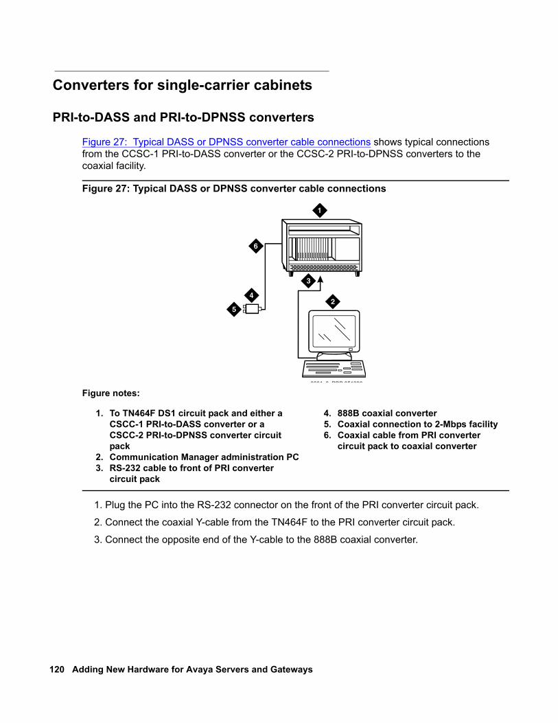
120 Adding New Hardware for Avaya Servers and Gateways
Converters for single-carrier cabinets
PRI-to-DASS and PRI-to-DPNSS converters
Figure 27: Typical DASS or DPNSS converter cable connections shows typical connections from the CCSC-1 PRI-to-DASS converter or the CCSC-2 PRI-to-DPNSS converters to the coaxial facility.
Figure 27: Typical DASS or DPNSS converter cable connections
1. Plug the PC into the RS-232 connector on the front of the PRI converter circuit pack.
2. Connect the coaxial Y-cable from the TN464F to the PRI converter circuit pack.
3. Connect the opposite end of the Y-cable to the 888B coaxial converter.
Figure notes:
1. To TN464F DS1 circuit pack and either a CSCC-1 PRI-to-DASS converter or a CSCC-2 PRI-to-DPNSS converter circuit pack
2. Communication Manager administration PC3. RS-232 cable to front of PRI converter
circuit pack
4. 888B coaxial converter5. Coaxial connection to 2-Mbps facility6. Coaxial cable from PRI converter
circuit pack to coaxial converter
0001 0 RBP 051396
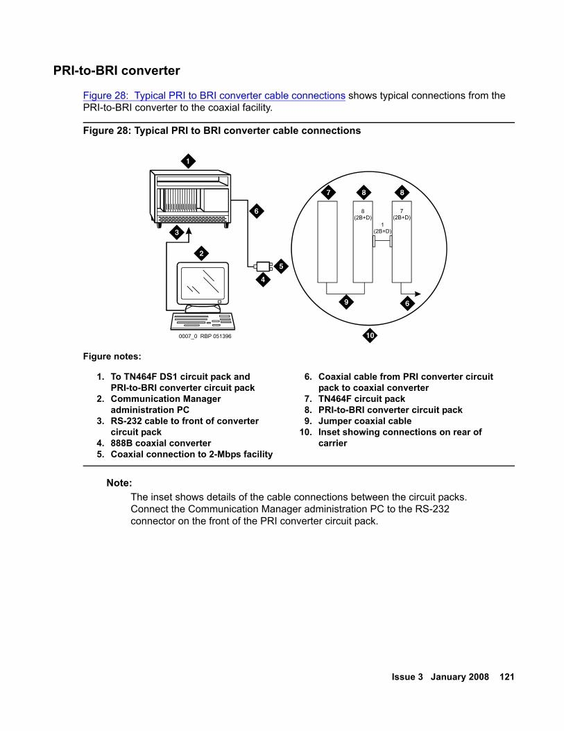
Issue 3 January 2008 121
PRI-to-BRI converter
Figure 28: Typical PRI to BRI converter cable connections shows typical connections from the PRI-to-BRI converter to the coaxial facility.
Figure 28: Typical PRI to BRI converter cable connections
Note:Note: The inset shows details of the cable connections between the circuit packs.
Connect the Communication Manager administration PC to the RS-232 connector on the front of the PRI converter circuit pack.
Figure notes:
1. To TN464F DS1 circuit pack and PRI-to-BRI converter circuit pack
2. Communication Manager administration PC
3. RS-232 cable to front of converter circuit pack
4. 888B coaxial converter5. Coaxial connection to 2-Mbps facility
6. Coaxial cable from PRI converter circuit pack to coaxial converter
7. TN464F circuit pack8. PRI-to-BRI converter circuit pack9. Jumper coaxial cable
10. Inset showing connections on rear of carrier
0007_0 RBP 051396
7(2B+D)
1(2B+D)
8(2B+D)
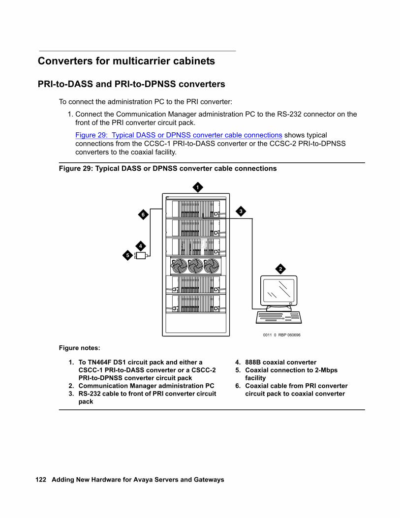
122 Adding New Hardware for Avaya Servers and Gateways
Converters for multicarrier cabinets
PRI-to-DASS and PRI-to-DPNSS converters
To connect the administration PC to the PRI converter:
1. Connect the Communication Manager administration PC to the RS-232 connector on the front of the PRI converter circuit pack.
Figure 29: Typical DASS or DPNSS converter cable connections shows typical connections from the CCSC-1 PRI-to-DASS converter or the CCSC-2 PRI-to-DPNSS converters to the coaxial facility.
Figure 29: Typical DASS or DPNSS converter cable connections
Figure notes:
1. To TN464F DS1 circuit pack and either a CSCC-1 PRI-to-DASS converter or a CSCC-2 PRI-to-DPNSS converter circuit pack
2. Communication Manager administration PC3. RS-232 cable to front of PRI converter circuit
pack
4. 888B coaxial converter5. Coaxial connection to 2-Mbps
facility6. Coaxial cable from PRI converter
circuit pack to coaxial converter
ALARMS
EMER TRCARD
IN
USE
ENT
ER/Y
ESN
EX
T/N
OBA
CKAUDIX
BO
OT
/S
HU
TDO
WN
0011 0 RBP 060696
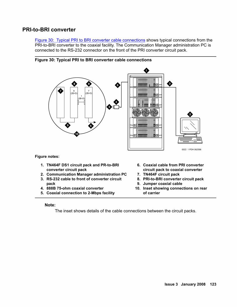
Issue 3 January 2008 123
PRI-to-BRI converter
Figure 30: Typical PRI to BRI converter cable connections shows typical connections from the PRI-to-BRI converter to the coaxial facility. The Communication Manager administration PC is connected to the RS-232 connector on the front of the PRI converter circuit pack.
Figure 30: Typical PRI to BRI converter cable connections
Note:Note: The inset shows details of the cable connections between the circuit packs.
Figure notes:
1. TN464F DS1 circuit pack and PR-to-BRI converter circuit pack
2. Communication Manager administration PC3. RS-232 cable to front of converter circuit
pack4. 888B 75-ohm coaxial converter5. Coaxial connection to 2-Mbps facility
6. Coaxial cable from PRI converter circuit pack to coaxial converter
7. TN464F circuit pack8. PRI-to-BRI converter circuit pack9. Jumper coaxial cable
10. Inset showing connections on rear of carrier
ALARMS
EMER TRCARD
IN
USE
EN
TER
/YE
SN
EXT
/NO
BAC
KAUDIX
BOO
T/
SHUT
DO
WN
0022 1 PDH 062596
7(2B+D)
1(2B+D)
8(2B+D)
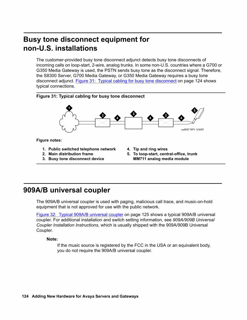
124 Adding New Hardware for Avaya Servers and Gateways
Busy tone disconnect equipment fornon-U.S. installations
The customer-provided busy tone disconnect adjunct detects busy tone disconnects of incoming calls on loop-start, 2-wire, analog trunks. In some non-U.S. countries where a G700 or G350 Media Gateway is used, the PSTN sends busy tone as the disconnect signal. Therefore, the S8300 Server, G700 Media Gateway, or G350 Media Gateway requires a busy tone disconnect adjunct. Figure 31: Typical cabling for busy tone disconnect on page 124 shows typical connections.
Figure 31: Typical cabling for busy tone disconnect
909A/B universal couplerThe 909A/B universal coupler is used with paging, malicious call trace, and music-on-hold equipment that is not approved for use with the public network.
Figure 32: Typical 909A/B universal coupler on page 125 shows a typical 909A/B universal coupler. For additional installation and switch setting information, see 909A/909B Universal Coupler Installation Instructions, which is usually shipped with the 909A/909B Universal Coupler.
Note:Note: If the music source is registered by the FCC in the USA or an equivalent body,
you do not require the 909A/B universal coupler.
Figure notes:
1. Public switched telephone network2. Main distribution frame3. Busy tone disconnect device
4. Tip and ring wires5. To loop-start, central-office, trunk
MM711 analog media module
cydf057 RPY 123097
1
2 234 4 4
5
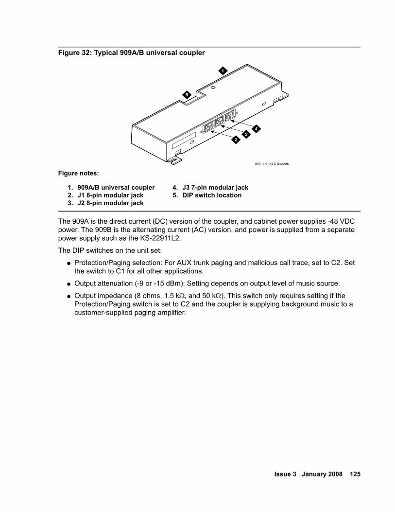
Issue 3 January 2008 125
Figure 32: Typical 909A/B universal coupler
The 909A is the direct current (DC) version of the coupler, and cabinet power supplies -48 VDC power. The 909B is the alternating current (AC) version, and power is supplied from a separate power supply such as the KS-22911L2.
The DIP switches on the unit set:
● Protection/Paging selection: For AUX trunk paging and malicious call trace, set to C2. Set the switch to C1 for all other applications.
● Output attenuation (-9 or -15 dBm): Setting depends on output level of music source.
● Output impedance (8 ohms, 1.5 kΩ, and 50 kΩ). This switch only requires setting if the Protection/Paging switch is set to C2 and the coupler is supplying background music to a customer-supplied paging amplifier.
Figure notes:
1. 909A/B universal coupler2. J1 8-pin modular jack3. J2 8-pin modular jack
4. J3 7-pin modular jack5. DIP switch location
909 brkt KLC 042296
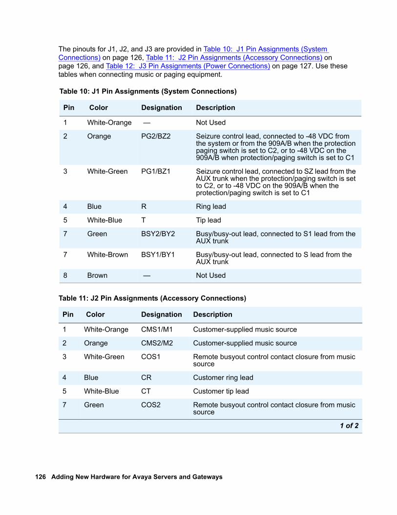
126 Adding New Hardware for Avaya Servers and Gateways
The pinouts for J1, J2, and J3 are provided in Table 10: J1 Pin Assignments (System Connections) on page 126, Table 11: J2 Pin Assignments (Accessory Connections) on page 126, and Table 12: J3 Pin Assignments (Power Connections) on page 127. Use these tables when connecting music or paging equipment.
Table 10: J1 Pin Assignments (System Connections)
Pin Color Designation Description
1 White-Orange — Not Used
2 Orange PG2/BZ2 Seizure control lead, connected to -48 VDC from the system or from the 909A/B when the protection paging switch is set to C2, or to -48 VDC on the 909A/B when protection/paging switch is set to C1
3 White-Green PG1/BZ1 Seizure control lead, connected to SZ lead from the AUX trunk when the protection/paging switch is set to C2, or to -48 VDC on the 909A/B when the protection/paging switch is set to C1
4 Blue R Ring lead
5 White-Blue T Tip lead
7 Green BSY2/BY2 Busy/busy-out lead, connected to S1 lead from the AUX trunk
7 White-Brown BSY1/BY1 Busy/busy-out lead, connected to S lead from the AUX trunk
8 Brown — Not Used
Table 11: J2 Pin Assignments (Accessory Connections)
Pin Color Designation Description
1 White-Orange CMS1/M1 Customer-supplied music source
2 Orange CMS2/M2 Customer-supplied music source
3 White-Green COS1 Remote busyout control contact closure from music source
4 Blue CR Customer ring lead
5 White-Blue CT Customer tip lead
7 Green COS2 Remote busyout control contact closure from music source
1 of 2
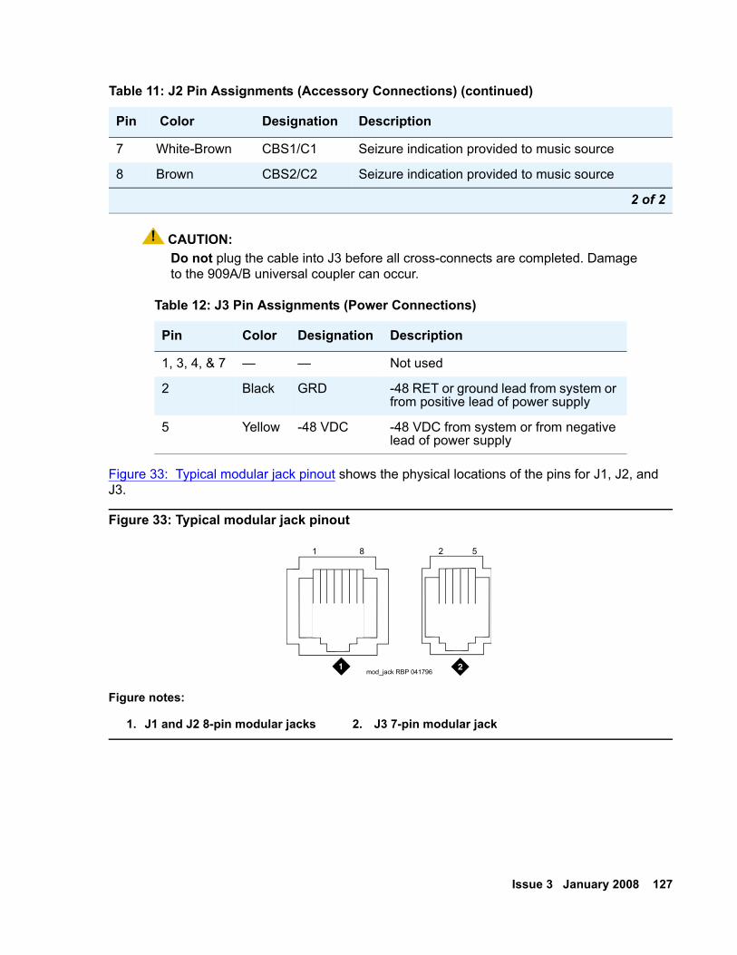
Issue 3 January 2008 127
! CAUTION:CAUTION: Do not plug the cable into J3 before all cross-connects are completed. Damage
to the 909A/B universal coupler can occur.
Figure 33: Typical modular jack pinout shows the physical locations of the pins for J1, J2, and J3.
Figure 33: Typical modular jack pinout
7 White-Brown CBS1/C1 Seizure indication provided to music source
8 Brown CBS2/C2 Seizure indication provided to music source
Table 12: J3 Pin Assignments (Power Connections)
Pin Color Designation Description
1, 3, 4, & 7 — — Not used
2 Black GRD -48 RET or ground lead from system or from positive lead of power supply
5 Yellow -48 VDC -48 VDC from system or from negative lead of power supply
Figure notes:
1. J1 and J2 8-pin modular jacks 2. J3 7-pin modular jack
Table 11: J2 Pin Assignments (Accessory Connections) (continued)
Pin Color Designation Description
2 of 2
1 8 2 5
mod_jack RBP 041796
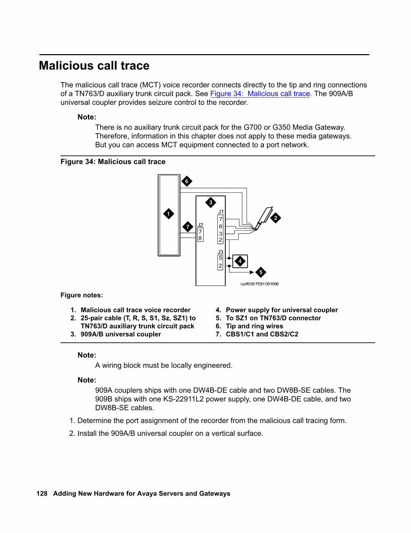
128 Adding New Hardware for Avaya Servers and Gateways
Malicious call traceThe malicious call trace (MCT) voice recorder connects directly to the tip and ring connections of a TN763/D auxiliary trunk circuit pack. See Figure 34: Malicious call trace. The 909A/B universal coupler provides seizure control to the recorder.
Note:Note: There is no auxiliary trunk circuit pack for the G700 or G350 Media Gateway.
Therefore, information in this chapter does not apply to these media gateways. But you can access MCT equipment connected to a port network.
Figure 34: Malicious call trace
Note:Note: A wiring block must be locally engineered.
Note:Note: 909A couplers ships with one DW4B-DE cable and two DW8B-SE cables. The
909B ships with one KS-22911L2 power supply, one DW4B-DE cable, and two DW8B-SE cables.
1. Determine the port assignment of the recorder from the malicious call tracing form.
2. Install the 909A/B universal coupler on a vertical surface.
Figure notes:
1. Malicious call trace voice recorder2. 25-pair cable (T, R, S, S1, Sz, SZ1) to
TN763/D auxiliary trunk circuit pack3. 909A/B universal coupler
4. Power supply for universal coupler5. To SZ1 on TN763/D connector6. Tip and ring wires7. CBS1/C1 and CBS2/C2
cydf038 PDH 091696
J2
J3
J1
52
7
78 2
36
Issue 3 January 2008 129
3. Connect the SZ, SZ1, S, and S1 leads from the 909A/B to an auxiliary trunk circuit pack.
a. Tip and ring connect from the voice recorder to the auxiliary trunk circuit pack (J1 on the 909A/B).
b. CBS1/C1 and CBS2/C2 connect from the voice recorder to J2 on the 909A/B.
4. On the 909A/B universal coupler:
a. Connect seizure control voltage of from -9 to -70 Volts to the PG2/BZ2 connection (pin 2 of J1). Switching voltage to the PG2/BZ2 connection can be from the 909A/B -48 VDC supply.
b. Connect SZ1 to the ground lead of the DC power source used for PG2/BZ2.
c. Set S1 to the “C2” position. Set S2 position 7 to “OPEN”.
d. Connect an approved -48 VDC power source to the -48 and GRD terminals (pins 5 and 2, respectively, of J3 on the 909A/B).
5. Administer the switch for the call trace device.
Note:Note: For more information about installation, see 909A/909B Universal Coupler
Installation Instructions, which is usually shipped with the 909A/909B Universal Coupler.
Music-on-hold With the music-on-hold (MOH) feature, a caller hears music when that caller is placed on hold. Music-on-hold can be provided:
through either
● a two-wire TN2183 analog line circuit pack, or equivalent,
or
● auxiliary trunk circuit pack to a customer-supplied music source.
Music-on-hold is available on the following media gateways:
● MCC1
● SCC1
● CMC1
● G600
● G650
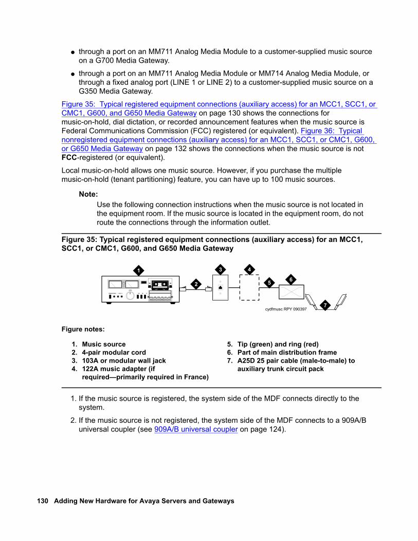
130 Adding New Hardware for Avaya Servers and Gateways
● through a port on an MM711 Analog Media Module to a customer-supplied music source on a G700 Media Gateway.
● through a port on an MM711 Analog Media Module or MM714 Analog Media Module, or through a fixed analog port (LINE 1 or LINE 2) to a customer-supplied music source on a G350 Media Gateway.
Figure 35: Typical registered equipment connections (auxiliary access) for an MCC1, SCC1, or CMC1, G600, and G650 Media Gateway on page 130 shows the connections for music-on-hold, dial dictation, or recorded announcement features when the music source is Federal Communications Commission (FCC) registered (or equivalent). Figure 36: Typical nonregistered equipment connections (auxiliary access) for an MCC1, SCC1, or CMC1, G600, or G650 Media Gateway on page 132 shows the connections when the music source is not FCC-registered (or equivalent).
Local music-on-hold allows one music source. However, if you purchase the multiple music-on-hold (tenant partitioning) feature, you can have up to 100 music sources.
Note:Note: Use the following connection instructions when the music source is not located in
the equipment room. If the music source is located in the equipment room, do not route the connections through the information outlet.
Figure 35: Typical registered equipment connections (auxiliary access) for an MCC1, SCC1, or CMC1, G600, and G650 Media Gateway
1. If the music source is registered, the system side of the MDF connects directly to the system.
2. If the music source is not registered, the system side of the MDF connects to a 909A/B universal coupler (see 909A/B universal coupler on page 124).
Figure notes:
1. Music source2. 4-pair modular cord3. 103A or modular wall jack4. 122A music adapter (if
required—primarily required in France)
5. Tip (green) and ring (red)6. Part of main distribution frame7. A25D 25 pair cable (male-to-male) to
auxiliary trunk circuit pack
cydfmusc RPY 090397
1
2
3 4
5 6
7

Issue 3 January 2008 131
Registered music source
See Figure 35: Typical registered equipment connections (auxiliary access) for an MCC1, SCC1, or CMC1, G600, and G650 Media Gateway on page 130 to install a registered music source.
1. Determine feature port assignment from Feature-Related System Parameters form.
2. Install music source according to the manufacturer instructions.
3. Install patch cord/jumper wires at the main distribution frame.
4. Administer the switch for the new equipment.
Nonregistered music source
See Figure 36: Typical nonregistered equipment connections (auxiliary access) for an MCC1, SCC1, or CMC1, G600, or G650 Media Gateway on page 132 and Figure 37: Connections to nonregistered music-on-hold using analog line for an MCC1, SCC1, or CMC1, G600, or G650 Media Gateway on page 133 when installing a nonregistered music source.
1. Determine feature port assignment from Feature-Related System Parameters Form.
2. Install the music source according to the manufacturer instructions.
3. Connect a cable from the assigned port carrier slot to J1 on the 909A/B universal coupler. For more information, see 909A/B universal coupler on page 124. A wiring block must be locally engineered.
a. Connect the T-lead at pin 5 and the R-lead at pin 4 of J1 on the 909A/B universal coupler to the corresponding leads from the TN2183.
b. Connect the CT-lead at pin 5 and the CR-lead at pin 4 of J2 on the 909A/B universal coupler to the MDF.
4. Install patch cord/jumper wires at the MDF to connect tip and ring to the information outlet at the music source.
5. Set the Protection/Paging switch to C1.
6. Connect a modular cord from the information outlet to the music source.
7. Connect -48V to pin 5 and -48V RET to pin 2 of J3 on the 909A/B. The power source can be an 1151A, 1151A2, or other approved power supply.
8. Administer the switch for the new equipment.
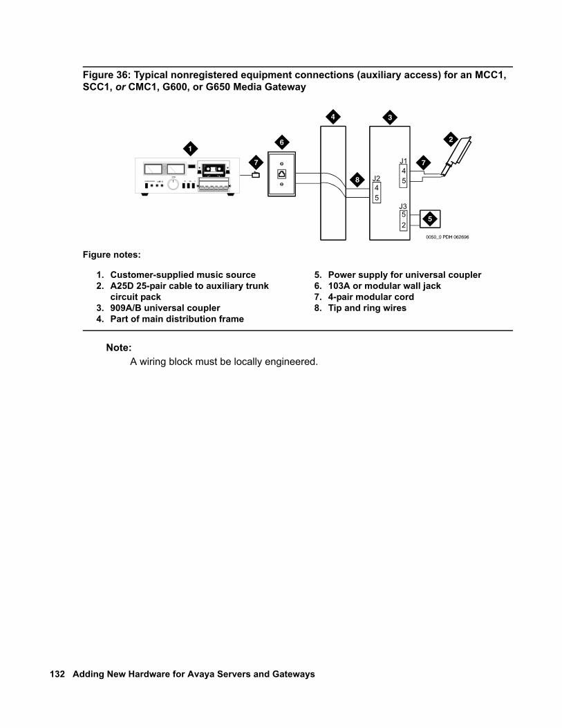
132 Adding New Hardware for Avaya Servers and Gateways
Figure 36: Typical nonregistered equipment connections (auxiliary access) for an MCC1, SCC1, or CMC1, G600, or G650 Media Gateway
Note:Note: A wiring block must be locally engineered.
Figure notes:
1. Customer-supplied music source 2. A25D 25-pair cable to auxiliary trunk
circuit pack3. 909A/B universal coupler4. Part of main distribution frame
5. Power supply for universal coupler6. 103A or modular wall jack7. 4-pair modular cord8. Tip and ring wires
J2
J3
J1
52
45
45
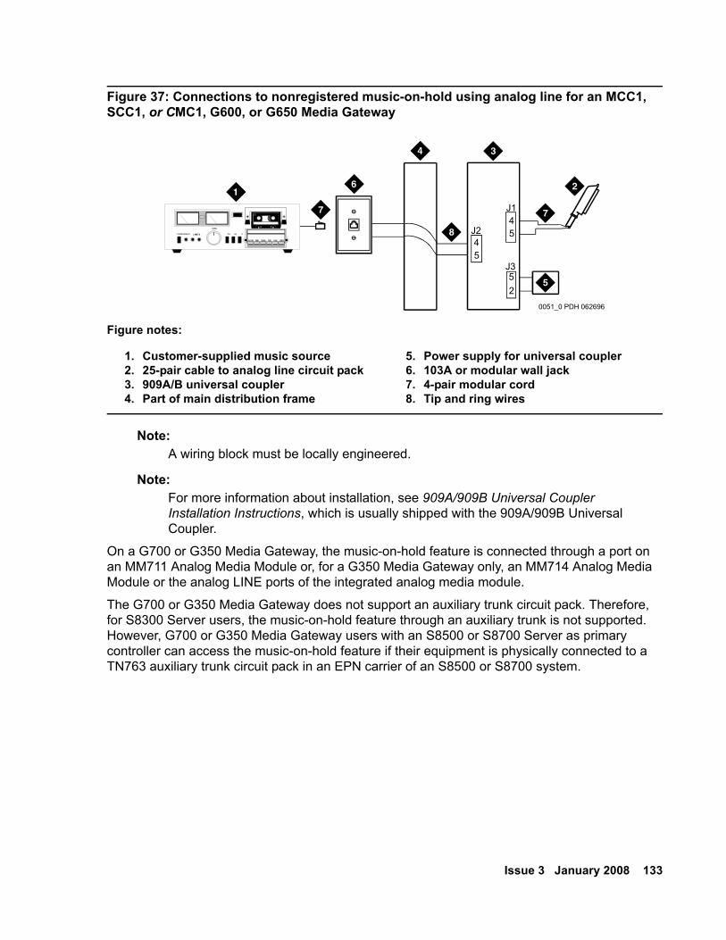
Issue 3 January 2008 133
Figure 37: Connections to nonregistered music-on-hold using analog line for an MCC1, SCC1, or CMC1, G600, or G650 Media Gateway
Note:Note: A wiring block must be locally engineered.
Note:Note: For more information about installation, see 909A/909B Universal Coupler
Installation Instructions, which is usually shipped with the 909A/909B Universal Coupler.
On a G700 or G350 Media Gateway, the music-on-hold feature is connected through a port on an MM711 Analog Media Module or, for a G350 Media Gateway only, an MM714 Analog Media Module or the analog LINE ports of the integrated analog media module.
The G700 or G350 Media Gateway does not support an auxiliary trunk circuit pack. Therefore, for S8300 Server users, the music-on-hold feature through an auxiliary trunk is not supported. However, G700 or G350 Media Gateway users with an S8500 or S8700 Server as primary controller can access the music-on-hold feature if their equipment is physically connected to a TN763 auxiliary trunk circuit pack in an EPN carrier of an S8500 or S8700 system.
Figure notes:
1. Customer-supplied music source2. 25-pair cable to analog line circuit pack3. 909A/B universal coupler4. Part of main distribution frame
5. Power supply for universal coupler6. 103A or modular wall jack7. 4-pair modular cord8. Tip and ring wires
0051_0 PDH 062696
J2
J3
J1
52
45
45
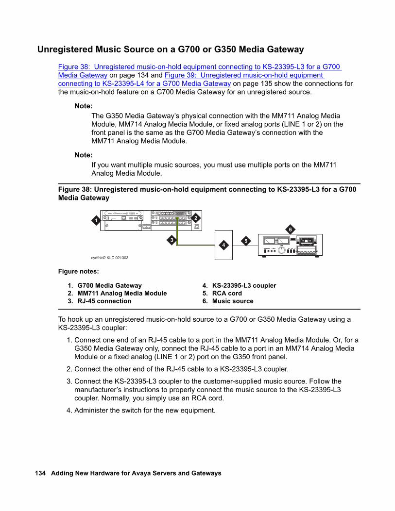
134 Adding New Hardware for Avaya Servers and Gateways
Unregistered Music Source on a G700 or G350 Media Gateway
Figure 38: Unregistered music-on-hold equipment connecting to KS-23395-L3 for a G700 Media Gateway on page 134 and Figure 39: Unregistered music-on-hold equipment connecting to KS-23395-L4 for a G700 Media Gateway on page 135 show the connections for the music-on-hold feature on a G700 Media Gateway for an unregistered source.
Note:Note: The G350 Media Gateway’s physical connection with the MM711 Analog Media
Module, MM714 Analog Media Module, or fixed analog ports (LINE 1 or 2) on the front panel is the same as the G700 Media Gateway’s connection with the MM711 Analog Media Module.
Note:Note: If you want multiple music sources, you must use multiple ports on the MM711
Analog Media Module.
Figure 38: Unregistered music-on-hold equipment connecting to KS-23395-L3 for a G700 Media Gateway
To hook up an unregistered music-on-hold source to a G700 or G350 Media Gateway using a KS-23395-L3 coupler:
1. Connect one end of an RJ-45 cable to a port in the MM711 Analog Media Module. Or, for a G350 Media Gateway only, connect the RJ-45 cable to a port in an MM714 Analog Media Module or a fixed analog (LINE 1 or 2) port on the G350 front panel.
2. Connect the other end of the RJ-45 cable to a KS-23395-L3 coupler.
3. Connect the KS-23395-L3 coupler to the customer-supplied music source. Follow the manufacturer’s instructions to properly connect the music source to the KS-23395-L3 coupler. Normally, you simply use an RCA cord.
4. Administer the switch for the new equipment.
Figure notes:
1. G700 Media Gateway2. MM711 Analog Media Module3. RJ-45 connection
4. KS-23395-L3 coupler5. RCA cord6. Music source
cydfhld2 KLC 021303
ALM
TST
ACT
1 2 3 4 5 6 87
ALM
TST
ACT
1 2 3 4 5 6 87
REMOVE
ALM
TST
ACT
OK TOSHUT DOWN
SERVICES USB 1 USB 2
E1/T1 EIA 530A DCE
ALM
TST
ACT
SIG
EISO EMSM EOSI
1 2
4
6
53
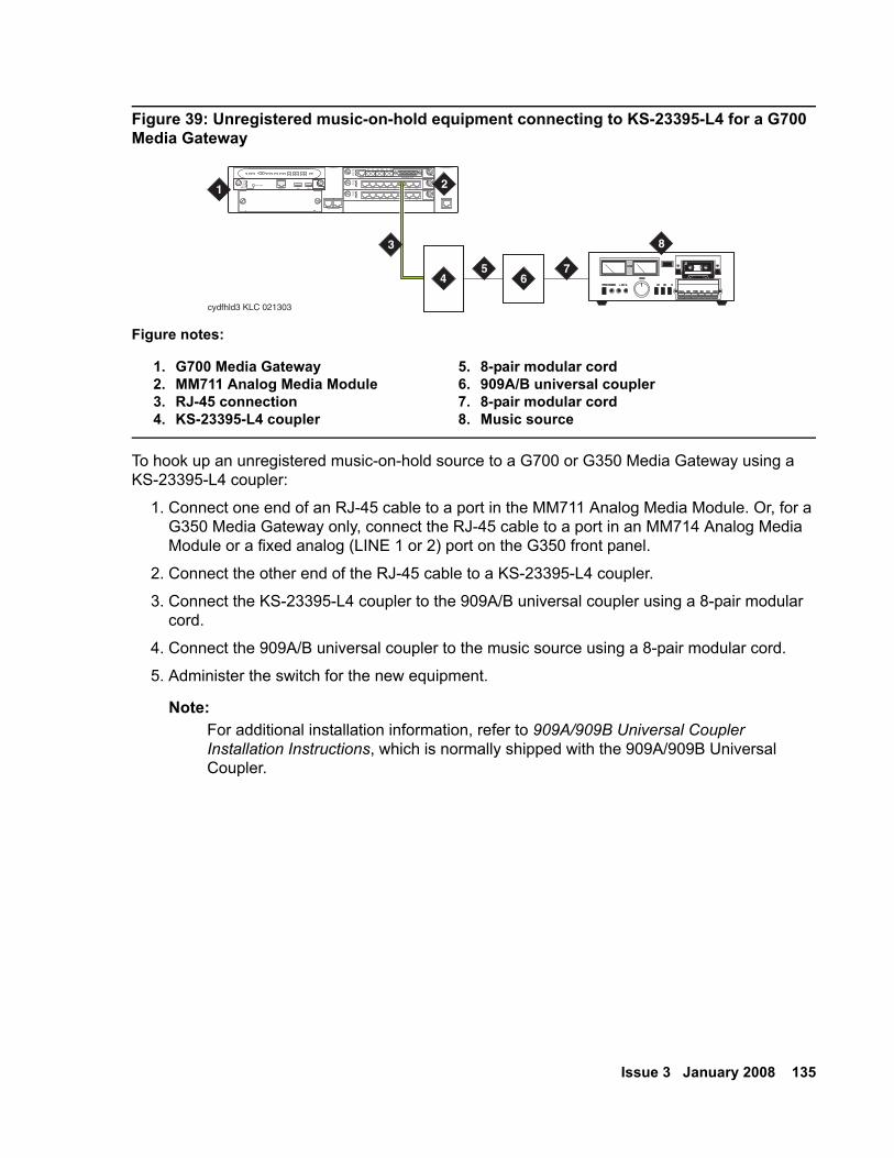
Issue 3 January 2008 135
Figure 39: Unregistered music-on-hold equipment connecting to KS-23395-L4 for a G700 Media Gateway
To hook up an unregistered music-on-hold source to a G700 or G350 Media Gateway using a KS-23395-L4 coupler:
1. Connect one end of an RJ-45 cable to a port in the MM711 Analog Media Module. Or, for a G350 Media Gateway only, connect the RJ-45 cable to a port in an MM714 Analog Media Module or a fixed analog (LINE 1 or 2) port on the G350 front panel.
2. Connect the other end of the RJ-45 cable to a KS-23395-L4 coupler.
3. Connect the KS-23395-L4 coupler to the 909A/B universal coupler using a 8-pair modular cord.
4. Connect the 909A/B universal coupler to the music source using a 8-pair modular cord.
5. Administer the switch for the new equipment.
Note:Note: For additional installation information, refer to 909A/909B Universal Coupler
Installation Instructions, which is normally shipped with the 909A/909B Universal Coupler.
Figure notes:
1. G700 Media Gateway2. MM711 Analog Media Module3. RJ-45 connection4. KS-23395-L4 coupler
5. 8-pair modular cord6. 909A/B universal coupler7. 8-pair modular cord8. Music source
cydfhld3 KLC 021303
ALM
TST
ACT
1 2 3 4 5 6 87
ALM
TST
ACT
1 2 3 4 5 6 87
REMOVE
ALM
TST
ACT
OK TOSHUT DOWN
SERVICES USB 1 USB 2
E1/T1 EIA 530A DCE
ALM
TST
ACT
SIG
EISO EMSM EOSI
1 2
54 6
7
83
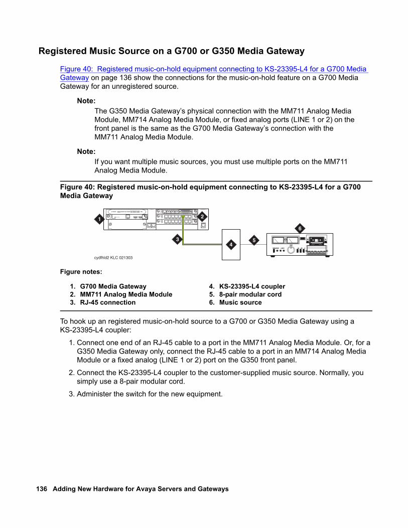
136 Adding New Hardware for Avaya Servers and Gateways
Registered Music Source on a G700 or G350 Media Gateway
Figure 40: Registered music-on-hold equipment connecting to KS-23395-L4 for a G700 Media Gateway on page 136 show the connections for the music-on-hold feature on a G700 Media Gateway for an unregistered source.
Note:Note: The G350 Media Gateway’s physical connection with the MM711 Analog Media
Module, MM714 Analog Media Module, or fixed analog ports (LINE 1 or 2) on the front panel is the same as the G700 Media Gateway’s connection with the MM711 Analog Media Module.
Note:Note: If you want multiple music sources, you must use multiple ports on the MM711
Analog Media Module.
Figure 40: Registered music-on-hold equipment connecting to KS-23395-L4 for a G700 Media Gateway
To hook up an registered music-on-hold source to a G700 or G350 Media Gateway using a KS-23395-L4 coupler:
1. Connect one end of an RJ-45 cable to a port in the MM711 Analog Media Module. Or, for a G350 Media Gateway only, connect the RJ-45 cable to a port in an MM714 Analog Media Module or a fixed analog (LINE 1 or 2) port on the G350 front panel.
2. Connect the KS-23395-L4 coupler to the customer-supplied music source. Normally, you simply use a 8-pair modular cord.
3. Administer the switch for the new equipment.
Figure notes:
1. G700 Media Gateway2. MM711 Analog Media Module3. RJ-45 connection
4. KS-23395-L4 coupler5. 8-pair modular cord6. Music source
cydfhld2 KLC 021303
ALM
TST
ACT
1 2 3 4 5 6 87
ALM
TST
ACT
1 2 3 4 5 6 87
REMOVE
ALM
TST
ACT
OK TOSHUT DOWN
SERVICES USB 1 USB 2
E1/T1 EIA 530A DCE
ALM
TST
ACT
SIG
EISO EMSM EOSI
1 2
4
6
53
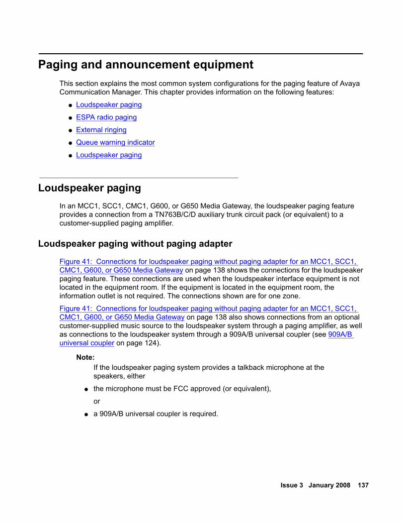
Issue 3 January 2008 137
Paging and announcement equipmentThis section explains the most common system configurations for the paging feature of Avaya Communication Manager. This chapter provides information on the following features:
● Loudspeaker paging
● ESPA radio paging
● External ringing
● Queue warning indicator
● Loudspeaker paging
Loudspeaker pagingIn an MCC1, SCC1, CMC1, G600, or G650 Media Gateway, the loudspeaker paging feature provides a connection from a TN763B/C/D auxiliary trunk circuit pack (or equivalent) to a customer-supplied paging amplifier.
Loudspeaker paging without paging adapter
Figure 41: Connections for loudspeaker paging without paging adapter for an MCC1, SCC1, CMC1, G600, or G650 Media Gateway on page 138 shows the connections for the loudspeaker paging feature. These connections are used when the loudspeaker interface equipment is not located in the equipment room. If the equipment is located in the equipment room, the information outlet is not required. The connections shown are for one zone.
Figure 41: Connections for loudspeaker paging without paging adapter for an MCC1, SCC1, CMC1, G600, or G650 Media Gateway on page 138 also shows connections from an optional customer-supplied music source to the loudspeaker system through a paging amplifier, as well as connections to the loudspeaker system through a 909A/B universal coupler (see 909A/B universal coupler on page 124).
Note:Note: If the loudspeaker paging system provides a talkback microphone at the
speakers, either
● the microphone must be FCC approved (or equivalent),
or
● a 909A/B universal coupler is required.
138 Adding New Hardware for Avaya Servers and Gateways
Figure 41: Connections for loudspeaker paging without paging adapter for an MCC1, SCC1, CMC1, G600, or G650 Media Gateway
Note:Note: On the 25-pair cable to TN763B/C/D auxiliary trunk circuit pack, SZ1 connects to
GRD on key 10. The 50 points amphenol is connected to the back of a G600 or G650 Media Gateway.
Loudspeaker paging access without universal coupler
To install the loudspeaker equipment:
1. Determine port assignment of paging zone(s) from loudspeaker paging form.
2. At the main distribution frame, locate the connecting block and terminals assigned to the selected port.
3. On the locally engineered wiring block, place a strap between terminals S and SZ. Place a strap between terminals S1 and SZ1.
4. Install patch cord/jumper wires at the main distribution frame.
5. Connect a 2-pair line cord, with a modular plug at one end, from the information outlet to the paging amplifier of the loudspeaker system.
6. Install loudspeaker equipment according to the manufacturer instructions.
7. Administer the switch for the new equipment.
Figure notes:
1. 25-pair cable to TN763B/C/D auxiliary trunk circuit pack
2. Loudspeaker paging system3. 909A/B universal coupler (if required)4. Part of main distribution frame (MDF)
circuits 1-165. Paging amplifier
6. Music source for background music over loudspeakers (optional)
7. 103A or modular wall jack8. To SZ1 on TN763 connector9. Tip and ring wires
10. -48 VDC power supply for 909B
cydfnzm KLC 091202
J2
J3
J1
5
1
2
2
7
4
45
236
51
23
4
5
7
8
9
9
106
Issue 3 January 2008 139
Loudspeaker paging with universal coupler
An information outlet provides access to loudspeaker paging. The system side of the main distribution frame connects to a 909A/B universal coupler. Make provisions for the DC power that the 909A/B universal coupler requires, such as a 1151A, 1151A2, or other approved -48VDC power supply.
Six leads (T, R, SZ, SZ1, S, and S1) connect the adapter to an auxiliary trunk circuit pack located in a port carrier.
1. Determine port assignment of paging zone(s) from loudspeaker Paging form.
2. Identify carrier slot and label both ends of an A25D (male to male) cable.
3. Connect a cable from the 909A/B to the system side of the main distribution frame. A wiring block must be locally engineered.
4. 909A/B universal coupler on page 124 provides details of the connections between the 909A/B universal coupler and the wiring blocks.
! CAUTION:CAUTION: Damage to the 909A/B might occur if the cable is plugged into J3 before all
cross-connects are completed.
5. On the 909A/B universal coupler:
● Connect seizure control voltage of from -9 to -70 volts to the PG2/BZ2 connection (pin 2 of J1). Switching voltage to the PG2/BZ2 connection can be from the 909-48-volt supply.
● Connect a -48 VDC power source to the -48 and GRD terminals on the 909A/B.
6. Install patch cord/jumper wires at the main distribution frame.
7. Connect a 2-pair line cord (modular plug at one end) from the information outlet to the loudspeaker system.
8. Install loudspeaker equipment according to the manufacturer instructions.
9. Connect an approved -48 VDC power source to the -48 and GRD terminals (pins 5 and 2, respectively, of J3).
10. Administer the switch for the new equipment.
Note:Note: For more information about installation, see 909A/909B Universal Coupler
Installation Instructions, which is usually shipped with the 909A/909B Universal Coupler.
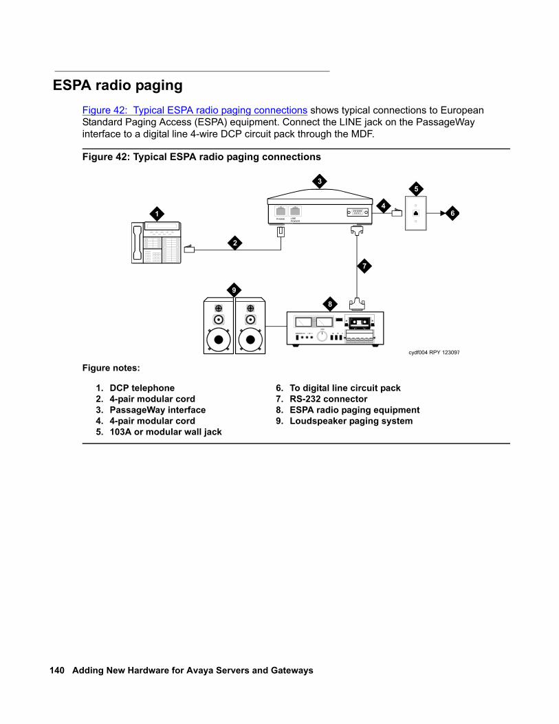
140 Adding New Hardware for Avaya Servers and Gateways
ESPA radio pagingFigure 42: Typical ESPA radio paging connections shows typical connections to European Standard Paging Access (ESPA) equipment. Connect the LINE jack on the PassageWay interface to a digital line 4-wire DCP circuit pack through the MDF.
Figure 42: Typical ESPA radio paging connections
Figure notes:
1. DCP telephone 2. 4-pair modular cord3. PassageWay interface4. 4-pair modular cord5. 103A or modular wall jack
6. To digital line circuit pack7. RS-232 connector8. ESPA radio paging equipment9. Loudspeaker paging system
cydf004 RPY 123097
PHONE LINEPOWER
1
2
3
4
5
6
7
8
9
Issue 3 January 2008 141
External ringingConnections for external ringing are at an information outlet. The system side of the main distribution frame (MDF) is connected to a TN2183 (or equivalent) analog line circuit pack in any of the following gateways:
● MCC1
● SCC1
● CMC1
● G600,
● G650
Note:Note: Up to three devices can be connected to one analog line circuit pack port.
1. Wire the ringing device to the information outlet.
2. Administer the switch for the new equipment.
Queue warning indicatorThe connections for the queue warning indicator are the same as external ringing. An AC indicator (light) such as a 21C49 can be used in a Uniform Call Distribution/Direct Departmental Calling (UCD/DDC) queue. The light is connected to an information outlet. The system side of the MDF is connected to an analog line circuit pack located in a port carrier.
1. Wire the queue warning indicator to the information outlet.
2. Administer the switch for the new equipment.
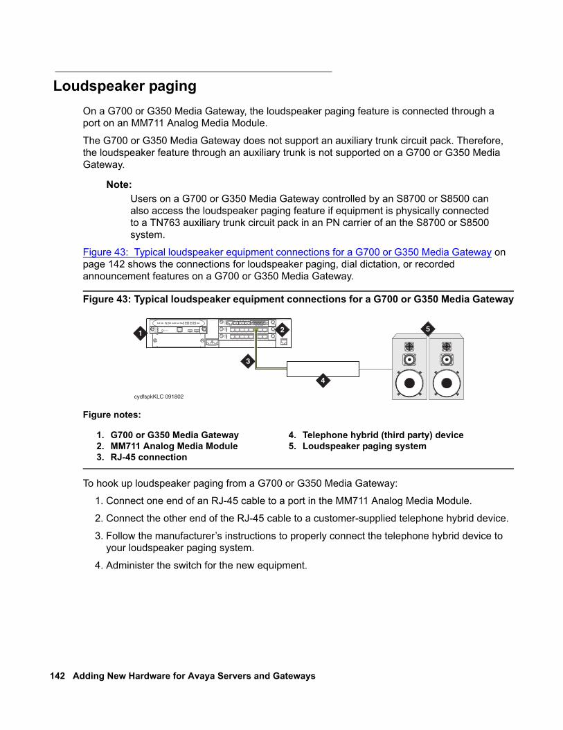
142 Adding New Hardware for Avaya Servers and Gateways
Loudspeaker pagingOn a G700 or G350 Media Gateway, the loudspeaker paging feature is connected through a port on an MM711 Analog Media Module.
The G700 or G350 Media Gateway does not support an auxiliary trunk circuit pack. Therefore, the loudspeaker feature through an auxiliary trunk is not supported on a G700 or G350 Media Gateway.
Note:Note: Users on a G700 or G350 Media Gateway controlled by an S8700 or S8500 can
also access the loudspeaker paging feature if equipment is physically connected to a TN763 auxiliary trunk circuit pack in an PN carrier of an the S8700 or S8500 system.
Figure 43: Typical loudspeaker equipment connections for a G700 or G350 Media Gateway on page 142 shows the connections for loudspeaker paging, dial dictation, or recorded announcement features on a G700 or G350 Media Gateway.
Figure 43: Typical loudspeaker equipment connections for a G700 or G350 Media Gateway
To hook up loudspeaker paging from a G700 or G350 Media Gateway:
1. Connect one end of an RJ-45 cable to a port in the MM711 Analog Media Module.
2. Connect the other end of the RJ-45 cable to a customer-supplied telephone hybrid device.
3. Follow the manufacturer’s instructions to properly connect the telephone hybrid device to your loudspeaker paging system.
4. Administer the switch for the new equipment.
Figure notes:
1. G700 or G350 Media Gateway2. MM711 Analog Media Module3. RJ-45 connection
4. Telephone hybrid (third party) device5. Loudspeaker paging system
cydfspkKLC 091802
ALM
TST
ACT
1 2 3 4 5 6 87
ALM
TST
ACT
1 2 3 4 5 6 87
REMOVE
ALM
TST
ACT
OK TOSHUT DOWN
SERVICES USB 1 USB 2
E1/T1 EIA 530A DCE
ALM
TST
ACT
SIG
EISO EMSM EOSI
1 2
4
3
5
Issue 3 January 2008 143
Adjunct information sourcesThis section lists documents you can use for installation of some of the key adjunct systems that you can connect.
You can access or download the latest version of documentation from the Avaya Support Web site at http:/avaya.com/support. You must have access to the Internet and a copy of Adobe Reader installed on your personal computer.
To download the latest version of this documentation:
1. Access the Avaya Support Web site at http://support.avaya.com.
2. At the top of the page, click in the Search text box.
3. Type the documentation number and click the arrow button.
The system displays the list of documentation issues. Click the latest version of the documentation.
Call Management System For more information about installing Call Management System, see the following documents:
● Avaya Call Management System (CMS) Release 13 Software Installation, Maintenance, and Troubleshooting Guide (07-300738)
● Avaya Call Management System Sun Fire V880/V890 Computer Hardware Installation, Maintenance, and Troubleshooting (585-215-116)
● Avaya Call Management System Sun Blade 100/150 Workstation Hardware Installation, Maintenance, and Troubleshooting (585-310-783)
144 Adding New Hardware for Avaya Servers and Gateways
INTUITY AUDIX Messaging SystemsFor more information about installing INTUITY AUDIX Messaging systems, see the following documents:
● For INTUITY AUDIX Release 5.1 Messaging, see INTUITY Messaging Solutions Release 5 Installation for New Systems on the INTUITY Messaging Solutions Release 5 Documentation CD-ROM (585-313-803)
● For INTUITY AUDIX LX Messaging, see INTUITY AUDIX LX Installation Checklist on the INTUITY AUDIX LX Release 1 Documentation CD-ROM (585-313-818)
● For IA770 INTUITY AUDIX Messaging, see IA 770 INTUITY AUDIX R1.1 Installation Instructions and Checklist, 585-313-159, on the Avaya S8300, S8500, and S8700 Server Library CD-ROM, 555-233-825.
Avaya Modular Messaging SystemFor more information about installing Avaya Modular Messaging systems, see Modular Messaging Release 3 Documentation CD-ROM (700376627).
ASAI and DEFINITY LAN GatewayFor more information about installing ASAI systems and DEFINITY LAN Gateway, see Avaya MultiVantage ASAI Applications over MAPD (555-230-136) and Avaya Communication Manager Release 2.0 ASAI Technical Reference (555-230-220) on the Avaya Communication Manager Release 2.0 ASAI Documents CD-ROM (585-246-801).
Another document related to ASAI is Avaya CVLAN Server 9.0 for Linux Installation and Basic Administration, which is available at http://avaya.com/support. Click the following links: Support>Technical Database>Contact Centers/CRM>CTI>CVLAN Server for Linux R9.
Avaya Interactive ResponseFor more information about installing Avaya Interactive Response systems, see Avaya Interactive Response R1.2.1 Install and Troubleshooting Guide (07-300180) on the Avaya Interactive Response R1.2.1 Documentation CD (07-300181).

Issue 3 January 2008 145
Avaya Extension to CellularFor more information about installing Avaya Extension to Cellular systems, see the Avaya Extension to Cellular User’s Guide (210-100-700).
Property Management SystemsFor more information about installing property management systems, see Guestworks and DEFINITY Systems Technician Handbook for Hospitality Installations (555-231-743).
Call Accounting SystemsFor more information about installing Call Accounting Systems, see one of the following documents:
● The online help or documentation included with the eCAS software CD-ROM
● For Guestworks Server INTUITY Lodging Call Accounting System, see GuestWorks and DEFINITY Systems Technician Handbook for Hospitality Installations (555-231-743).
DEFINITY Wireless Business SystemFor more information about installing DEFINITY Wireless Business System, see DEFINITY Wireless Business System Installation and Test (555-232-102).

146 Adding New Hardware for Avaya Servers and Gateways
Issue 3 January 2008 147
Index
Numerical120A ICSU . . . . . . . . . . . . . . . . . . . . 101120A2 ICSU . . . . . . . . . . . . . . . . . . . . 98888B converter . . . . . . . . . . . . . . . . . . 120909A coupler, DC version . . . . . . . . . . . . . 125909A/B universal coupler . 124, 128, 130, 131, 137, 139
DIP switch settings . . . . . . . . . . . . . . . 125909B coupler, AC version . . . . . . . . . . . . . 125
KS-22911 power supply for . . . . . . . . . . . 125
Aadapters
TN2302AP Amphenol adapter . . . . . . . . . . 20adding
a port network . . . . . . . . . . . . . . . . . 57CO trunk . . . . . . . . . . . . . . . . . . .46, 49DID trunk. . . . . . . . . . . . . . . . . . . . 47DS1 tie trunk . . . . . . . . . . . . . . . . . . 49FX trunk . . . . . . . . . . . . . . . . . . .46, 49ISDN—PRI . . . . . . . . . . . . . . . . . . . 55OPS trunk . . . . . . . . . . . . . . . . . . . 49PCOL trunk . . . . . . . . . . . . . . . . . . 46tie trunk . . . . . . . . . . . . . . . . . . . . 47TN2464BP . . . . . . . . . . . . . . . . . . . 45TN464GP . . . . . . . . . . . . . . . . . . . 45TTC Japanese 2-Mbit trunks. . . . . . . . . . . 50WATS trunk . . . . . . . . . . . . . . . . .46, 49
administeringCDR data collection. . . . . . . . . . . . . . . 85CDR parameters . . . . . . . . . . . . . . . . 86Expansion Services Module (ESM) . . . . . . . 95external modems . . . . . . . . . . . . . . . . 119IP Media Processor . . . . . . . . . . . . . . . 21IP Media Resource . . . . . . . . . . . . . . . 32IPSI . . . . . . . . . . . . . . . . . . . . . . 66loopback jack. . . . . . . . . . . . . . . . . . 100multimedia call handling (MMCH) . . . . . . . . 93multimedia call handling (MMCH) endpoints . . . 93multimedia call handling (MMCH) one number complex
93Reliable Data Transport Tool . . . . . . . . . . 88TN799DP C-LAN circuit pack . . . . . . . . . . 15
alarm activation levelsetting . . . . . . . . . . . . . . . . . . . . . 68
assigning addresses . . . . . . . . . . . . . . . . 58asynchronous links. . . . . . . . . . . . . . . . . 96
Bbackplane I/O cables, replacing . . . . . . . . . . . 34busy tone disconnect . . . . . . . . . . . . . . . 124
Ccall detail recording (CDR)
administering data collection . . . . . . . . . . . 85administering parameters . . . . . . . . . . . . 86connecting equipment . . . . . . . . . . . . . . 84testing links . . . . . . . . . . . . . . . . . . . 86
calling queue . . . . . . . . . . . . . . . . . . . 141CAMA/E911 trunks . . . . . . . . . . . 50, 52, 53, 54circuit packs
installing . . . . . . . . . . . . . . . . . . 11, 69programmable . . . . . . . . . . . . . . . . . 17reusing . . . . . . . . . . . . . . . . . . . . . 59sorted by code . . . . . . . . . . . . . . . . . 43TN2183 analog line . . . . . . . . . . . . 129, 141TN2302AP . . . . . . . . . . . . . . . . . . . 17TN2501. . . . . . . . . . . . . . . . . . . . . 22TN799DP . . . . . . . . . . . . . . . . . . . . 12TNCCSC-1 PRI-to-DASS converter. . . . . 120, 122TNCCSC-2 PRI-to-DPNSS converter . . . . 120, 122TNPRI/BRI converter . . . . . . . . . . . 121, 123
C-LANadministering . . . . . . . . . . . . . . . . . . 15Ethernet adapter . . . . . . . . . . . . . . . . 14installing . . . . . . . . . . . . . . . . . . . . 13replacing WP cables with I/O twisted pairs . . . . 14testing external connection to LAN . . . . . . . . 16
clearing the ARP cache on the laptop . . . . . . . . 59CO trunk, adding . . . . . . . . . . . . . . . . 46, 49coaxial converter, 888B . . . . . . . . . . . . . . 120connecting a printer to a G700 or G350 Media Gateway96connections
CDR equipment . . . . . . . . . . . . . . . . . 84ITS
network . . . . . . . . . . . . . . . . . 19, 30connections, music-on-hold
FCC-registered equipment . . . . . . . . . . . 131non-FCC-registered equipment. . . . . . . . . 131
connectivityverifying IPSI . . . . . . . . . . . . . . . . . . 69
Critical Reliability . . . . . . . . . . . . . . . . 58, 67
148 Adding New Hardware for Avaya Servers and Gateways
DDHCP. . . . . . . . . . . . . . . . . . . . . . . 62DID trunk
adding . . . . . . . . . . . . . . . . . . . . . 47DS1 loopback jack . . . . . . . . . . . . . . . . . 98DS1 span . . . . . . . . . . . . . . . . . . . . . 99
T1 . . . . . . . . . . . . . . . . . . . . . . . 98DS1 tie trunk, adding. . . . . . . . . . . . . . . . 49
Eecho cancellation
with TN2464BP. . . . . . . . . . . . . . . . . 45with TN464GP . . . . . . . . . . . . . . . . . 45
endpoints . . . . . . . . . . . . . . . . . . . . . 92European Standard Paging Access (ESPA) radio paging
equipment . . . . . . . . . . . . . . . . . . . . 140Expansion Services Module (ESM) . . . . . . . . . 94
administration . . . . . . . . . . . . . . . . . 95installation . . . . . . . . . . . . . . . . . . . 94
external communications controller (ECC) . . . . . . 133external ringing . . . . . . . . . . . . . . . . . . 141
FFeature Access Code form . . . . . . . . . . . . . 52FX trunk, adding . . . . . . . . . . . . . . . . .46, 49
GG650 Media Gateway
installing . . . . . . . . . . . . . . . . . . . . 58
Hhard drive (S8730 Server) . . . . . . . . . . . . . 37High Reliability. . . . . . . . . . . . . . . . . .58, 67
II/O cables, replacing . . . . . . . . . . . . . . . . 34installing
circuit packs . . . . . . . . . . . . . . . . .11, 69Expansion Services Module (ESM) . . . . . . . 94IOLAN+ 104 terminal server . . . . . . . . . . . 71IPSI circuit pack . . . . . . . . . . . . . . . . 58loopback jack. . . . . . . . . . . . . . . . . . 99Reliable Data Transport Tool . . . . . . . . . . 87TN2302AP IP Media Processor . . . . . . . . . 18TN799DP C-LAN . . . . . . . . . . . . . . . . 13
integrated channel service unit (ICSU) . . . . . . . 98integration process
connectingITS to the network . . . . . . . . . . . . 19, 30
internal communications controller (ICC) . . . . . . 133IOLAN+ 104 terminal server . . . . . . . . . . . . . 71
installation . . . . . . . . . . . . . . . . . . . 71installing and administering . . . . . . . . . . . 72
IP addressassigning . . . . . . . . . . . . . . . . . . . . 58
IP connectivity hardware . . . . . . . . . . . . . . 11IP Media Processor
administering . . . . . . . . . . . . . . . . . . 21installing . . . . . . . . . . . . . . . . . . . . 18testing external connection to LAN . . . . . . . . 22verifying active call status . . . . . . . . . . . . 22
IP Media Resourceadministering . . . . . . . . . . . . . . . . . . 32testing external connection to LAN . . . . . . . . 33verifying active call status . . . . . . . . . . . . 33
IP services . . . . . . . . . . . . . . . . . . . . . 83IPSI . . . . . . . . . . . . . . . . . . . . . . . . 62
duplication . . . . . . . . . . . . . . . . . . . 67verifying translations. . . . . . . . . . . . . . . 69
IPSI circuit pack . . . . . . . . . . . . . . . . . . 58administering and enabling. . . . . . . . . . . . 66assigning IP addresses . . . . . . . . . . . . . 58installing . . . . . . . . . . . . . . . . . . . . 58verifying connectivity . . . . . . . . . . . . . . 69
ISDN adapters . . . . . . . . . . . . . . . . . . .119ISDN converters . . . . . . . . . . . . . . . . . .119
for multicarrier cabinets . . . . . . . . . . . . 122for single-carrier cabinets . . . . . . . . . . . 120PRI-to-BRI . . . . . . . . . . . . . . . . 121, 123PRI-to-DASS . . . . . . . . . . . . . . . 120, 122PRI-to-DPNSS . . . . . . . . . . . . . . 120, 122
ISDN—PRIadding . . . . . . . . . . . . . . . . . . . . . 55
KKS-22911 power supply. . . . . . . . . . . . . . 125KS-22911L2 power supply . . . . . . . . . . . . 128
Lloopback jack . . . . . . . . . . . . . . . . . . . 98
administration . . . . . . . . . . . . . . . . . 100installation . . . . . . . . . . . . . . . . . . . 99
Mmain distribution frame (MDF) . . . . . . . . . . . 141malicious call trace (MCT). . . . . . . . . . . . . 128Media Gateway
G650 . . . . . . . . . . . . . . . . . . . . . . 58
Issue 3 January 2008 149
modems, external . . . . . . . . . . . . . . . . . 116administration . . . . . . . . . . . . . . . . . 119hardware to configure . . . . . . . . . . . . . . 116Multi-Tech MT5634ZBA-USB . . . . . . . . . . 118Multi-Tech MT5634ZBA-V92 . . . . . . . . . . 118Paradyne COMSPHERE 3810 Plus . . . . . . . 117Paradyne COMSPHERE 3811 Plus . . . . . . . 117Paradyne COMSPHERE 3910. . . . . . . . . . 117
multimedia call handling (MMCH) . . . . . . . . . . 92administering endpoints . . . . . . . . . . . . . 93administering one number complex . . . . . . . 93administering the system . . . . . . . . . . . . 93connecting endpoints . . . . . . . . . . . . . . 92
Multi-Tech MT5634ZBA-USB modems . . . . . . . 118Multi-Tech MT5634ZBA-V92 modems. . . . . . . . 118music-on-hold (MOH) . . . . . . . . . . . . . . . 129
connecting FCC-registered equipment . . . . . . 131connecting non-FCC-registered equipment . . . . 131
Nnetwork
adding a port network . . . . . . . . . . . . . . 57ITS
connecting . . . . . . . . . . . . . . . .19, 30network interface . . . . . . . . . . . . . . . . . 101node names . . . . . . . . . . . . . . . . . . . . 83
OOPS, adding. . . . . . . . . . . . . . . . . . . . 49
Ppaging equipment . . . . . . . . . . . . . . . . . 137
ESPA radio paging . . . . . . . . . . . . . . . 140external ringing . . . . . . . . . . . . . . . . . 141loudspeaker paging for G700 or G350 media gateways
142loudspeaker paging for MCC1, SCC1, CMC1, G600. or
G650 Media Gateways . . . . . . . . . . . . 137queue warning indicator . . . . . . . . . . . . . 141
Paradyne COMSPHERE modemsmodel 3810 Plus . . . . . . . . . . . . . . . . 117model 3811 Plus . . . . . . . . . . . . . . . . 117model 3910 . . . . . . . . . . . . . . . . . . 117
PCOL trunk, adding . . . . . . . . . . . . . . . . 46power supply (S8730 Server) . . . . . . . . . . . . 39printers
connecting to a G700 or G350 Media Gateway . . 96TCP/IP connections. . . . . . . . . . . . . . . 96
programmable circuit packsTN2302AP . . . . . . . . . . . . . . . . . . . 17TN2464BP . . . . . . . . . . . . . . . . . . . 45TN2501 . . . . . . . . . . . . . . . . . . . . 22
TN464GP. . . . . . . . . . . . . . . . . . . . 45TN799DP . . . . . . . . . . . . . . . . . . . . 12
Qqueue warning indicator. . . . . . . . . . . . . . 141
RReliability
Critical . . . . . . . . . . . . . . . . . . . 58, 67High . . . . . . . . . . . . . . . . . . . . 58, 67
Reliable Data Transport Tool (RDTT)administering . . . . . . . . . . . . . . . . . . 88downloading . . . . . . . . . . . . . . . . . . 87installing . . . . . . . . . . . . . . . . . . . . 87
SS8730 Server . . . . . . . . . . . . . . . . . . . 37service laptop
connecting . . . . . . . . . . . . . . . . . . . 59static IP address . . . . . . . . . . . . . . . . . . 59switch-to-call accounting link, testing. . . . . . . 86, 97
TT1 DS1 span . . . . . . . . . . . . . . . . . . . . 98TCP/IP connections . . . . . . . . . . . . . . . . 96terminal server . . . . . . . . . . . . . . . . . . . 71
administering IP node names . . . . . . . . . . 83administering IP services . . . . . . . . . . . . 83IOLAN+ 104 . . . . . . . . . . . . . . . . . . 71
testing, switch-to-call accounting link. . . . . . . 86, 97tie trunk
adding . . . . . . . . . . . . . . . . . . . . . 47TN2183 analog line circuit pack . . . . . . . . 129, 141TN2302AP Amphenol adapter . . . . . . . . . . . . 20TN2302AP IP Media Processor . . . . . . . . . . . 17TN2312AP IPSI . . . . . . . . . . . . . . . . . . 62TN2312BP IPSI . . . . . . . . . . . . . . . . . . 62TN2501 Voice over the LAN circuit pack . . . . . . . 22TN2501AP (integrated announcements)
faceplate LEDs and interpretation . . . . . . . . 24TN2602AP IP Media Resource 320 . . . . . . . . . 26TN429 circuit pack . . . . . . . . . . . . . . . . . 52TN799DP C-LAN circuit pack . . . . . . . . . . . . 12
administering . . . . . . . . . . . . . . . . . . 15installing . . . . . . . . . . . . . . . . . . 13, 15
TNCCSC-1 PRI-to-DASS converter . . . . . . 120, 122TNCCSC-2 PRI-to-DPNSS converter . . . . . 120, 122TNPRI/BRI converter . . . . . . . . . . . . . 121, 123translations
verifying IPSI . . . . . . . . . . . . . . . . . . 69
150 Adding New Hardware for Avaya Servers and Gateways
translations, CDR parameters . . . . . . . . . .86, 97trunks
adding . . . . . . . . . . . . . . . . . . . . . 46CAMA/E911 . . . . . . . . . . . . . 50, 52, 53, 54
TTC Japanese 2-Mbit trunks, adding . . . . . . . . 50
UUniform Call Distribution/Direct Departmental Calling (UCD/
DDC) queue . . . . . . . . . . . . . . . . . . . 141
VVAL See TN2501 Voice over the LAN.Voice over LAN
testing external connection to LAN . . . . . . . . 26
WWATS trunk, adding . . . . . . . . . . . . . . .46, 49wideband endpoints
non-signaling configuration . . . . . . . . . . . 88remote port module . . . . . . . . . . . . . . . 91signaling configuration . . . . . . . . . . . . . 89