administration for the avaya g250 and avaya g350...
TRANSCRIPT
Administration for the Avaya G250 and Avaya G350 Media Gateways
03-300436Issue 2
February 2006

© 2006 Avaya Inc.All Rights Reserved.
NoticeWhile reasonable efforts were made to ensure that the information in this document was complete and accurate at the time of printing, Avaya Inc. can assume no liability for any errors. Changes and corrections to the information in this document may be incorporated in future releases.
For full legal page information, please see the complete document, Avaya Legal Page for Software Documentation, Document number 03-600758.To locate this document on the website, simply go to http://www.avaya.com/support and search for the document number in the search box.
Documentation disclaimerAvaya Inc. is not responsible for any modifications, additions, or deletions to the original published version of this documentation unless such modifications, additions, or deletions were performed by Avaya. Customer and/or End User agree to indemnify and hold harmless Avaya, Avaya's agents, servants and employees against all claims, lawsuits, demands and judgments arising out of, or in connection with, subsequent modifications, additions or deletions to this documentation to the extent made by the Customer or End User.
Link disclaimerAvaya Inc. is not responsible for the contents or reliability of any linked Web sites referenced elsewhere within this documentation, and Avaya does not necessarily endorse the products, services, or information described or offered within them. We cannot guarantee that these links will work all of the time and we have no control over the availability of the linked pages.
WarrantyAvaya Inc. provides a limited warranty on this product. Refer to your sales agreement to establish the terms of the limited warranty. In addition, Avaya’s standard warranty language, as well as information regarding support for this product, while under warranty, is available through the following Web site:http://www.avaya.com/support
Copyright Except where expressly stated otherwise, the Product is protected by copyright and other laws respecting proprietary rights. Unauthorized reproduction, transfer, and or use can be a criminal, as well as a civil, offense under the applicable law.
Avaya supportAvaya provides a telephone number for you to use to report problems or to ask questions about your product. The support telephone number is 1-800-242-2121 in the United States. For additional support telephone numbers, see the Avaya Web site:http://www.avaya.com/support
Issue 2 February 2006 3
About this Book . . . . . . . . . . . . . . . . . . . . . . . . . . . . . . . 17Overview . . . . . . . . . . . . . . . . . . . . . . . . . . . . . . . . . . . . . . . . 17Audience . . . . . . . . . . . . . . . . . . . . . . . . . . . . . . . . . . . . . . . . 17Downloading this book and updates from the Web . . . . . . . . . . . . . . . . . 17
Downloading this book . . . . . . . . . . . . . . . . . . . . . . . . . . . . . . 17Related resources . . . . . . . . . . . . . . . . . . . . . . . . . . . . . . . . . . . 18Technical assistance . . . . . . . . . . . . . . . . . . . . . . . . . . . . . . . . . 19
Within the US. . . . . . . . . . . . . . . . . . . . . . . . . . . . . . . . . . . . 19International . . . . . . . . . . . . . . . . . . . . . . . . . . . . . . . . . . . . 19
Trademarks. . . . . . . . . . . . . . . . . . . . . . . . . . . . . . . . . . . . . . . 19Sending us comments. . . . . . . . . . . . . . . . . . . . . . . . . . . . . . . . . 20
Chapter 1: Introduction . . . . . . . . . . . . . . . . . . . . . . . . . . . 21
Chapter 2: Configuration overview. . . . . . . . . . . . . . . . . . . . . 25Installation and setup overview. . . . . . . . . . . . . . . . . . . . . . . . . . . . 25Configuration using CLI . . . . . . . . . . . . . . . . . . . . . . . . . . . . . . . . 27Configuration using GUI applications . . . . . . . . . . . . . . . . . . . . . . . . 27Saving configuration changes . . . . . . . . . . . . . . . . . . . . . . . . . . . . 28Firmware version control . . . . . . . . . . . . . . . . . . . . . . . . . . . . . . . 29
Chapter 3: Accessing the Avaya G250/G350 Media Gateway . . . . . . 31Accessing the CLI . . . . . . . . . . . . . . . . . . . . . . . . . . . . . . . . . . . 31
CLI Overview . . . . . . . . . . . . . . . . . . . . . . . . . . . . . . . . . . . . 32CLI contexts . . . . . . . . . . . . . . . . . . . . . . . . . . . . . . . . . . 32CLI help . . . . . . . . . . . . . . . . . . . . . . . . . . . . . . . . . . . . . 32
Accessing the CLI locally . . . . . . . . . . . . . . . . . . . . . . . . . . . . . 33Accessing CLI via local network . . . . . . . . . . . . . . . . . . . . . . . 33Accessing CLI with a console device . . . . . . . . . . . . . . . . . . . . 33
Accessing the CLI via modem . . . . . . . . . . . . . . . . . . . . . . . . . . 34Accessing the CLI via a USB modem. . . . . . . . . . . . . . . . . . . . . 34Accessing the CLI via a serial modem . . . . . . . . . . . . . . . . . . . . 35Accessing the CLI via a modem connection to the S8300 . . . . . . . . . 36
Accessing Avaya IW . . . . . . . . . . . . . . . . . . . . . . . . . . . . . . . . . . 36Accessing GIW. . . . . . . . . . . . . . . . . . . . . . . . . . . . . . . . . . . . . 38Accessing PIM . . . . . . . . . . . . . . . . . . . . . . . . . . . . . . . . . . . . . 40Accessing Avaya Communication Manager . . . . . . . . . . . . . . . . . . . . . 40Managing login permissions . . . . . . . . . . . . . . . . . . . . . . . . . . . . . 41
Contents
Contents
4 Administration for the Avaya G250 and Avaya G350 Media Gateways
Security overview . . . . . . . . . . . . . . . . . . . . . . . . . . . . . . . . . 41Managing users and passwords . . . . . . . . . . . . . . . . . . . . . . . . . 42
Privilege level . . . . . . . . . . . . . . . . . . . . . . . . . . . . . . . . . 42Configuring usernames . . . . . . . . . . . . . . . . . . . . . . . . . . . . 42
SSH protocol support . . . . . . . . . . . . . . . . . . . . . . . . . . . . . . . 43SSH Configuration . . . . . . . . . . . . . . . . . . . . . . . . . . . . . . . 44
SCP protocol support . . . . . . . . . . . . . . . . . . . . . . . . . . . . . . . 44RADIUS authentication . . . . . . . . . . . . . . . . . . . . . . . . . . . . . . 45802.1x protocol. . . . . . . . . . . . . . . . . . . . . . . . . . . . . . . . . . . 46
Authentication Modes . . . . . . . . . . . . . . . . . . . . . . . . . . . . . 46Configuring 802.1x . . . . . . . . . . . . . . . . . . . . . . . . . . . . . . 47Manual re-authentication . . . . . . . . . . . . . . . . . . . . . . . . . . . 50Optional 802.1x commands . . . . . . . . . . . . . . . . . . . . . . . . . . 50Displaying 802.1x parameters. . . . . . . . . . . . . . . . . . . . . . . . . 51
Special security features . . . . . . . . . . . . . . . . . . . . . . . . . . . . . . . 54Enabling and disabling recovery password . . . . . . . . . . . . . . . . . . . 54Enabling and disabling telnet access . . . . . . . . . . . . . . . . . . . . . . 54Enabling SYN cookies . . . . . . . . . . . . . . . . . . . . . . . . . . . . . . . 55
Overview of SYN cookies . . . . . . . . . . . . . . . . . . . . . . . . . . . 55Configuring SYN cookies . . . . . . . . . . . . . . . . . . . . . . . . . . . 56Maintaining SYN cookies . . . . . . . . . . . . . . . . . . . . . . . . . . . 57
Managed Security Services (MSS) . . . . . . . . . . . . . . . . . . . . . . . . 57MSS reporting mechanism . . . . . . . . . . . . . . . . . . . . . . . . . . 57Configuring MSS. . . . . . . . . . . . . . . . . . . . . . . . . . . . . . . . 58DoS attack classifications. . . . . . . . . . . . . . . . . . . . . . . . . . . 60Defining custom DoS classifications . . . . . . . . . . . . . . . . . . . . . 61CLI commands . . . . . . . . . . . . . . . . . . . . . . . . . . . . . . . . . 62Example . . . . . . . . . . . . . . . . . . . . . . . . . . . . . . . . . . . . 63
Chapter 4: Basic device configuration . . . . . . . . . . . . . . . . . . . 65Defining an interface . . . . . . . . . . . . . . . . . . . . . . . . . . . . . . . . . 65Configuring the Primary Management Interface (PMI) . . . . . . . . . . . . . . . 66Defining the default gateway . . . . . . . . . . . . . . . . . . . . . . . . . . . . . 67Configuring the Media Gateway Controller (MGC) . . . . . . . . . . . . . . . . . 67
The Media Gateway Controller (MGC) . . . . . . . . . . . . . . . . . . . . . . 68Survivability and migration options . . . . . . . . . . . . . . . . . . . . . . . 69Configuring the MGC list . . . . . . . . . . . . . . . . . . . . . . . . . . . . . 70Setting reset times. . . . . . . . . . . . . . . . . . . . . . . . . . . . . . . . . 71Accessing the registered MGC . . . . . . . . . . . . . . . . . . . . . . . . . . 72Monitoring the ICC or LSP . . . . . . . . . . . . . . . . . . . . . . . . . . . . 73
Contents
Issue 2 February 2006 5
DNS Resolver . . . . . . . . . . . . . . . . . . . . . . . . . . . . . . . . . . . . . 73DNS Resolver overview . . . . . . . . . . . . . . . . . . . . . . . . . . . . . . 73Typical DNS resolver application – VPN failover . . . . . . . . . . . . . . . . 74Configuring DNS Resolver . . . . . . . . . . . . . . . . . . . . . . . . . . . . 75
DNS Resolver configuration example . . . . . . . . . . . . . . . . . . . . 78Maintaining DNS Resolver . . . . . . . . . . . . . . . . . . . . . . . . . . . . 78
Showing DNS Resolver information . . . . . . . . . . . . . . . . . . . . . 78Clearing DNS Resolver counters . . . . . . . . . . . . . . . . . . . . . . . 79Viewing DNS Resolver logging . . . . . . . . . . . . . . . . . . . . . . . . 79
Viewing the status of the device . . . . . . . . . . . . . . . . . . . . . . . . . . . 79Version management . . . . . . . . . . . . . . . . . . . . . . . . . . . . . . . . . 81
File transfer . . . . . . . . . . . . . . . . . . . . . . . . . . . . . . . . . . . . 81Software and firmware upgrades . . . . . . . . . . . . . . . . . . . . . . . . . 82
Managing the firmware banks. . . . . . . . . . . . . . . . . . . . . . . . . 82Upgrading software and firmware . . . . . . . . . . . . . . . . . . . . . . 83
Managing configuration files . . . . . . . . . . . . . . . . . . . . . . . . . . . 85Listing the files on the Avaya G250/G350 Media Gateway . . . . . . . . . . . 85
Chapter 5: Configuring Standard Local Survivability(SLS) on the G250 . . . . . . . . . . . . . . . . . . . . . . . 87
SLS overview. . . . . . . . . . . . . . . . . . . . . . . . . . . . . . . . . . . . . . 87Call processing in SLS mode . . . . . . . . . . . . . . . . . . . . . . . . . . . 88Provisioning data . . . . . . . . . . . . . . . . . . . . . . . . . . . . . . . . . 89Entering SLS mode . . . . . . . . . . . . . . . . . . . . . . . . . . . . . . . . 90
Unregistered . . . . . . . . . . . . . . . . . . . . . . . . . . . . . . . . . . 90Setup . . . . . . . . . . . . . . . . . . . . . . . . . . . . . . . . . . . . . . 90Registered . . . . . . . . . . . . . . . . . . . . . . . . . . . . . . . . . . . 91Teardown . . . . . . . . . . . . . . . . . . . . . . . . . . . . . . . . . . . . 91
SLS interaction with specific G250/G350 features . . . . . . . . . . . . . . . 91SLS logging activities . . . . . . . . . . . . . . . . . . . . . . . . . . . . . . . 92
Configuring SLS . . . . . . . . . . . . . . . . . . . . . . . . . . . . . . . . . . . . 94Gathering provisioning data from PIM . . . . . . . . . . . . . . . . . . . . . . 94Enabling and disabling SLS on the G250 . . . . . . . . . . . . . . . . . . . . 98Manually configuring the SLS data through the CLI . . . . . . . . . . . . . . 99
Prerequisites . . . . . . . . . . . . . . . . . . . . . . . . . . . . . . . . . . 99Configuring the SLS data . . . . . . . . . . . . . . . . . . . . . . . . . . . 99
Chapter 6: Configuring Ethernet ports. . . . . . . . . . . . . . . . . . . 107Ethernet ports on the G250 . . . . . . . . . . . . . . . . . . . . . . . . . . . . . . 107Ethernet ports on the G350 . . . . . . . . . . . . . . . . . . . . . . . . . . . . . . 108
Contents
6 Administration for the Avaya G250 and Avaya G350 Media Gateways
Configuring switch Ethernet ports . . . . . . . . . . . . . . . . . . . . . . . . . . 108Switch Ethernet port commands . . . . . . . . . . . . . . . . . . . . . . . . . 109
Configuring the WAN Ethernet port . . . . . . . . . . . . . . . . . . . . . . . . . 110WAN Ethernet port traffic shaping . . . . . . . . . . . . . . . . . . . . . . . . 111Backup interfaces . . . . . . . . . . . . . . . . . . . . . . . . . . . . . . . . . 111WAN Ethernet port commands . . . . . . . . . . . . . . . . . . . . . . . . . . 111
Configuring DHCP client . . . . . . . . . . . . . . . . . . . . . . . . . . . . . . . 112DHCP client overview . . . . . . . . . . . . . . . . . . . . . . . . . . . . . . . 112DHCP client applications . . . . . . . . . . . . . . . . . . . . . . . . . . . . . 113DHCP client configuration . . . . . . . . . . . . . . . . . . . . . . . . . . . . 113Releasing and renewing a DHCP lease. . . . . . . . . . . . . . . . . . . . . . 115Maintaining DHCP client . . . . . . . . . . . . . . . . . . . . . . . . . . . . . 116Configuring DHCP client logging messages. . . . . . . . . . . . . . . . . . . 116
Configuring LLDP . . . . . . . . . . . . . . . . . . . . . . . . . . . . . . . . . . . 116Supported TLVs . . . . . . . . . . . . . . . . . . . . . . . . . . . . . . . . . . 117LLDP configuration . . . . . . . . . . . . . . . . . . . . . . . . . . . . . . . . 118
Supported ports for LLDP. . . . . . . . . . . . . . . . . . . . . . . . . . . 118
Chapter 7: Configuring logging . . . . . . . . . . . . . . . . . . . . . . 119Logging overview . . . . . . . . . . . . . . . . . . . . . . . . . . . . . . . . . . . 119Configuring a Syslog server . . . . . . . . . . . . . . . . . . . . . . . . . . . . . 120Configuring a log file . . . . . . . . . . . . . . . . . . . . . . . . . . . . . . . . . 123Configuring a session log. . . . . . . . . . . . . . . . . . . . . . . . . . . . . . . 124Configuring logging filters . . . . . . . . . . . . . . . . . . . . . . . . . . . . . . 126
Setting the logging filters . . . . . . . . . . . . . . . . . . . . . . . . . . . 126Severity levels . . . . . . . . . . . . . . . . . . . . . . . . . . . . . . . . . 127Applications to be filtered . . . . . . . . . . . . . . . . . . . . . . . . . . . 128
Logging configuration examples . . . . . . . . . . . . . . . . . . . . . . . . . . . 130Syslog server example . . . . . . . . . . . . . . . . . . . . . . . . . . . . 130Log file example . . . . . . . . . . . . . . . . . . . . . . . . . . . . . . . . 130Session log example. . . . . . . . . . . . . . . . . . . . . . . . . . . . . . 131
Chapter 8: Configuring VoIP QoS . . . . . . . . . . . . . . . . . . . . . 133VoIP overview . . . . . . . . . . . . . . . . . . . . . . . . . . . . . . . . . . . . . 133Configuring RTP and RTCP . . . . . . . . . . . . . . . . . . . . . . . . . . . . . . 134Configuring header compression . . . . . . . . . . . . . . . . . . . . . . . . . . 134
Header compression overview . . . . . . . . . . . . . . . . . . . . . . . . . . 134Configuring IPHC-type header compression . . . . . . . . . . . . . . . . . . 135Configuring VJ-type header compression . . . . . . . . . . . . . . . . . . . . 137
Contents
Issue 2 February 2006 7
Displaying and clearing header compression statistics . . . . . . . . . . . . 138Configuring QoS parameters . . . . . . . . . . . . . . . . . . . . . . . . . . . . . 138Configuring RTCP QoS parameters . . . . . . . . . . . . . . . . . . . . . . . . . 139Configuring RSVP parameters . . . . . . . . . . . . . . . . . . . . . . . . . . . . 140Configuring Weighted Fair VoIP Queuing (WFVQ) . . . . . . . . . . . . . . . . . 140
Chapter 9: Configuring the G250 and G350 for modem use . . . . . . . 141Configuring the USB port for modem use . . . . . . . . . . . . . . . . . . . . . . 141Configuring the console port for modem use . . . . . . . . . . . . . . . . . . . . 143
Chapter 10: Configuring WAN interfaces . . . . . . . . . . . . . . . . . 145WAN overview . . . . . . . . . . . . . . . . . . . . . . . . . . . . . . . . . . . . . 145Serial interface overview . . . . . . . . . . . . . . . . . . . . . . . . . . . . . . . 147
Frame Relay multipoint topology support . . . . . . . . . . . . . . . . . . . . 148Initial WAN configuration . . . . . . . . . . . . . . . . . . . . . . . . . . . . . . . 149
Configuring the Avaya MM340 E1/T1 WAN media module . . . . . . . . . . . 149E1/T1 default settings . . . . . . . . . . . . . . . . . . . . . . . . . . . . . 152
Configuring the Avaya MM342 USP WAN media module . . . . . . . . . . . . 153USP default settings . . . . . . . . . . . . . . . . . . . . . . . . . . . . . . 154
Configuring PPP . . . . . . . . . . . . . . . . . . . . . . . . . . . . . . . . . . 155Configuring PPPoE . . . . . . . . . . . . . . . . . . . . . . . . . . . . . . . . 155
PPPoE overview . . . . . . . . . . . . . . . . . . . . . . . . . . . . . . . . 156PPPoE configuration . . . . . . . . . . . . . . . . . . . . . . . . . . . . . 156
Configuring frame relay . . . . . . . . . . . . . . . . . . . . . . . . . . . . . . 159Verifying the WAN configuration and testing connectivity . . . . . . . . . . . 161
Backup interfaces . . . . . . . . . . . . . . . . . . . . . . . . . . . . . . . . . . . 162Backup commands . . . . . . . . . . . . . . . . . . . . . . . . . . . . . . . . 164
Modem dial backup . . . . . . . . . . . . . . . . . . . . . . . . . . . . . . . . . . 164Modem dial backup overview . . . . . . . . . . . . . . . . . . . . . . . . . . . 164Typical installations . . . . . . . . . . . . . . . . . . . . . . . . . . . . . . . . 167Configuring modem dial backup . . . . . . . . . . . . . . . . . . . . . . . . . 167Modem dial backup interactions with other features . . . . . . . . . . . . . . 171Configuration example . . . . . . . . . . . . . . . . . . . . . . . . . . . . . . 172Modem dial backup maintenance. . . . . . . . . . . . . . . . . . . . . . . . . 177
ICMP keepalive. . . . . . . . . . . . . . . . . . . . . . . . . . . . . . . . . . . . . 183Dynamic CAC . . . . . . . . . . . . . . . . . . . . . . . . . . . . . . . . . . . . . 186Object tracking. . . . . . . . . . . . . . . . . . . . . . . . . . . . . . . . . . . . . 187
Object tracking overview . . . . . . . . . . . . . . . . . . . . . . . . . . . . . 188Object tracking configuration. . . . . . . . . . . . . . . . . . . . . . . . . . . 188
Contents
8 Administration for the Avaya G250 and Avaya G350 Media Gateways
Configuring RTR . . . . . . . . . . . . . . . . . . . . . . . . . . . . . . . . 189Configuring object tracking . . . . . . . . . . . . . . . . . . . . . . . . . . 191
Object tracking maintenance . . . . . . . . . . . . . . . . . . . . . . . . . . . 194Showing RTR and object tracking configuration . . . . . . . . . . . . . . 194Viewing RTR and object trackers logging . . . . . . . . . . . . . . . . . . 194
RTR and object tracking configuration examples . . . . . . . . . . . . . . . . 195Example — tracking a single remote device . . . . . . . . . . . . . . . . . 195Example — tracking a group of devices . . . . . . . . . . . . . . . . . . . 196
Typical object tracking applications . . . . . . . . . . . . . . . . . . . . . . . 197Typical application – VPN failover using object tracking . . . . . . . . . . 198Typical application – backup for the WAN Fast Ethernet interface . . . . 198Typical application – interface backup via policy-based routing. . . . . . 201Typical application – tracking the DHCP client default route . . . . . . . . 202
Frame relay encapsulation features . . . . . . . . . . . . . . . . . . . . . . . . . 203Frame Relay Traffic Shaping and FRF.12 Fragmentation . . . . . . . . . . . . 203
Priority DLCI . . . . . . . . . . . . . . . . . . . . . . . . . . . . . . . . . . . . . . 204WAN configuration example . . . . . . . . . . . . . . . . . . . . . . . . . . . . . 204
PPP VoIP configuration . . . . . . . . . . . . . . . . . . . . . . . . . . . . . . 205Configuration Example for Site A. . . . . . . . . . . . . . . . . . . . . . . 206Configuration Example for Site B. . . . . . . . . . . . . . . . . . . . . . . 208
Chapter 11: Configuring PoE . . . . . . . . . . . . . . . . . . . . . . . . 209PoE overview. . . . . . . . . . . . . . . . . . . . . . . . . . . . . . . . . . . . . . 209
Introduction to PoE on the G250 and G350 . . . . . . . . . . . . . . . . . . . 209Load detection . . . . . . . . . . . . . . . . . . . . . . . . . . . . . . . . . . . 210
How the G250/G350 detects a powered device (PD). . . . . . . . . . . . . 210Plug and Play Operation. . . . . . . . . . . . . . . . . . . . . . . . . . . . 211
Powering devices . . . . . . . . . . . . . . . . . . . . . . . . . . . . . . . . . 211PoE configuration CLI commands . . . . . . . . . . . . . . . . . . . . . . . . . . 212PoE configuration examples . . . . . . . . . . . . . . . . . . . . . . . . . . . . . 212
Chapter 12: Configuring Emergency Transfer Relay (ETR). . . . . . . . 215ETR overview . . . . . . . . . . . . . . . . . . . . . . . . . . . . . . . . . . . . . 215Setting ETR state . . . . . . . . . . . . . . . . . . . . . . . . . . . . . . . . . . . 216Viewing ETR state . . . . . . . . . . . . . . . . . . . . . . . . . . . . . . . . . . . 217
Chapter 13: Configuring SNMP. . . . . . . . . . . . . . . . . . . . . . . 219SNMP configuration overview . . . . . . . . . . . . . . . . . . . . . . . . . . . . 219SNMP versions. . . . . . . . . . . . . . . . . . . . . . . . . . . . . . . . . . . . . 221
Contents
Issue 2 February 2006 9
SNMPv1. . . . . . . . . . . . . . . . . . . . . . . . . . . . . . . . . . . . . . . 221SNMPv2c . . . . . . . . . . . . . . . . . . . . . . . . . . . . . . . . . . . . . . 221SNMPv3. . . . . . . . . . . . . . . . . . . . . . . . . . . . . . . . . . . . . . . 222Users . . . . . . . . . . . . . . . . . . . . . . . . . . . . . . . . . . . . . . . . 222Groups . . . . . . . . . . . . . . . . . . . . . . . . . . . . . . . . . . . . . . . 223Views . . . . . . . . . . . . . . . . . . . . . . . . . . . . . . . . . . . . . . . . 224
Configuring SNMP traps . . . . . . . . . . . . . . . . . . . . . . . . . . . . . . . 225Configuring SNMP access . . . . . . . . . . . . . . . . . . . . . . . . . . . . . . 227Configuring dynamic trap manager . . . . . . . . . . . . . . . . . . . . . . . . . 228SNMP configuration examples . . . . . . . . . . . . . . . . . . . . . . . . . . . . 228
Chapter 14: Configuring contact closure . . . . . . . . . . . . . . . . . 231Contact closure overview . . . . . . . . . . . . . . . . . . . . . . . . . . . . . . . 231Contact closure hardware configuration. . . . . . . . . . . . . . . . . . . . . . . 232Contact closure software configuration . . . . . . . . . . . . . . . . . . . . . . . 232Showing contact closure status . . . . . . . . . . . . . . . . . . . . . . . . . . . 233
Chapter 15: Transferring and managing announcement files . . . . . . 235
Chapter 16: Configuring advanced switching . . . . . . . . . . . . . . . 239Configuring VLANs . . . . . . . . . . . . . . . . . . . . . . . . . . . . . . . . . . 239
VLAN overview. . . . . . . . . . . . . . . . . . . . . . . . . . . . . . . . . . . 240VLAN tagging . . . . . . . . . . . . . . . . . . . . . . . . . . . . . . . . . . . 241Multi VLAN binding . . . . . . . . . . . . . . . . . . . . . . . . . . . . . . . . 242G250/G350 VLAN table . . . . . . . . . . . . . . . . . . . . . . . . . . . . . . 242Ingress VLAN security. . . . . . . . . . . . . . . . . . . . . . . . . . . . . . . 243ICC-VLAN. . . . . . . . . . . . . . . . . . . . . . . . . . . . . . . . . . . . . . 243VLAN CLI commands . . . . . . . . . . . . . . . . . . . . . . . . . . . . . . . 243VLAN configuration examples . . . . . . . . . . . . . . . . . . . . . . . . . . 244
Configuring port redundancy (G350 only) . . . . . . . . . . . . . . . . . . . . . . 247Port redundancy overview . . . . . . . . . . . . . . . . . . . . . . . . . . . . 247Secondary port activation. . . . . . . . . . . . . . . . . . . . . . . . . . . . . 247Switchback . . . . . . . . . . . . . . . . . . . . . . . . . . . . . . . . . . . . . 248Port redundancy CLI commands . . . . . . . . . . . . . . . . . . . . . . . . . 248Port redundancy configuration examples . . . . . . . . . . . . . . . . . . . . 249
Configuring port mirroring . . . . . . . . . . . . . . . . . . . . . . . . . . . . . . 250Port mirroring overview . . . . . . . . . . . . . . . . . . . . . . . . . . . . . . 250Port mirroring constraints . . . . . . . . . . . . . . . . . . . . . . . . . . . . 250Port mirroring CLI commands . . . . . . . . . . . . . . . . . . . . . . . . . . 250
Contents
10 Administration for the Avaya G250 and Avaya G350 Media Gateways
Port mirroring configuration examples . . . . . . . . . . . . . . . . . . . . . 251Configuring spanning tree (G350 only) . . . . . . . . . . . . . . . . . . . . . . . 252
Spanning tree overview . . . . . . . . . . . . . . . . . . . . . . . . . . . . . . 252Spanning tree protocol . . . . . . . . . . . . . . . . . . . . . . . . . . . . 252Spanning tree per port. . . . . . . . . . . . . . . . . . . . . . . . . . . . . 253Rapid Spanning Tree Protocol (RSTP) . . . . . . . . . . . . . . . . . . . . 253
Spanning tree CLI commands . . . . . . . . . . . . . . . . . . . . . . . . . . 255Spanning tree configuration examples. . . . . . . . . . . . . . . . . . . . . . 256
Port classification . . . . . . . . . . . . . . . . . . . . . . . . . . . . . . . . . . . 258Port classification overview. . . . . . . . . . . . . . . . . . . . . . . . . . . . 258Port classification CLI commands . . . . . . . . . . . . . . . . . . . . . . . . 258Port classification configuration examples . . . . . . . . . . . . . . . . . . . 258
Chapter 17: Configuring monitoring applications. . . . . . . . . . . . . 261Configuring RMON. . . . . . . . . . . . . . . . . . . . . . . . . . . . . . . . . . . 261
RMON overview . . . . . . . . . . . . . . . . . . . . . . . . . . . . . . . . . . 261RMON CLI commands . . . . . . . . . . . . . . . . . . . . . . . . . . . . . . . 262RMON configuration examples . . . . . . . . . . . . . . . . . . . . . . . . . . 262
Configuring and analyzing RTP statistics . . . . . . . . . . . . . . . . . . . . . . 264Overview . . . . . . . . . . . . . . . . . . . . . . . . . . . . . . . . . . . . . . 264Configuring the RTP statistics application . . . . . . . . . . . . . . . . . . . 266
Viewing RTP statistics thresholds . . . . . . . . . . . . . . . . . . . . . . 266Configuring RTP statistics thresholds . . . . . . . . . . . . . . . . . . . . 268Enabling and resetting the RTP statistics application . . . . . . . . . . . 269Viewing application configuration . . . . . . . . . . . . . . . . . . . . . . 270Configuring QoS traps. . . . . . . . . . . . . . . . . . . . . . . . . . . . . 271Configuring QoS fault and clear traps . . . . . . . . . . . . . . . . . . . . 273Configuring the trap rate limiter . . . . . . . . . . . . . . . . . . . . . . . 273
Analyzing RTP statistics output . . . . . . . . . . . . . . . . . . . . . . . . . 274Viewing RTP statistics summary reports . . . . . . . . . . . . . . . . . . 274Viewing RTP session statistics . . . . . . . . . . . . . . . . . . . . . . . . 275Viewing QoS traps, QoS fault traps, and QoS clear traps. . . . . . . . . . 282Analyzing QoS trap output . . . . . . . . . . . . . . . . . . . . . . . . . . 283Analyzing QoS fault and clear trap output . . . . . . . . . . . . . . . . . . 286Viewing automatic traceroute results . . . . . . . . . . . . . . . . . . . . 287
RTP statistics examples. . . . . . . . . . . . . . . . . . . . . . . . . . . . . . 289Configuring the RTP statistics application for a sample network . . . . . 289A call over the WAN from an analog phone to an IP phone. . . . . . . . . 293A local call between an IP and an analog phone . . . . . . . . . . . . . . 295A remote call over the WAN from an IP phone to an IP phone . . . . . . . 297
Contents
Issue 2 February 2006 11
A conference call . . . . . . . . . . . . . . . . . . . . . . . . . . . . . . . 300RTP statistics CLI commands . . . . . . . . . . . . . . . . . . . . . . . . . . 302
Configuring and analyzing packet sniffing . . . . . . . . . . . . . . . . . . . . . 303Overview . . . . . . . . . . . . . . . . . . . . . . . . . . . . . . . . . . . . . . 303What can be captured . . . . . . . . . . . . . . . . . . . . . . . . . . . . . . . 304Configuring packet sniffing . . . . . . . . . . . . . . . . . . . . . . . . . . . . 305
Enabling packet sniffing. . . . . . . . . . . . . . . . . . . . . . . . . . . . 305Limiting packet sniffing to specific interfaces . . . . . . . . . . . . . . . . 305Creating a capture list . . . . . . . . . . . . . . . . . . . . . . . . . . . . . 306Defining rule criteria for a capture list . . . . . . . . . . . . . . . . . . . . 306Viewing the capture list . . . . . . . . . . . . . . . . . . . . . . . . . . . . 313Applying a capture list. . . . . . . . . . . . . . . . . . . . . . . . . . . . . 313Configuring packet sniffing settings . . . . . . . . . . . . . . . . . . . . . 314Starting the packet sniffing service . . . . . . . . . . . . . . . . . . . . . 315
Analyzing captured packets . . . . . . . . . . . . . . . . . . . . . . . . . . . 316Stopping the packet sniffing service . . . . . . . . . . . . . . . . . . . . . 316Viewing packet sniffing information . . . . . . . . . . . . . . . . . . . . . 316Uploading the capture file . . . . . . . . . . . . . . . . . . . . . . . . . . . 317Analyzing the capture file . . . . . . . . . . . . . . . . . . . . . . . . . . . 319
Simulating packets . . . . . . . . . . . . . . . . . . . . . . . . . . . . . . . . 321Packet sniffing CLI commands . . . . . . . . . . . . . . . . . . . . . . . . . . 321
General context . . . . . . . . . . . . . . . . . . . . . . . . . . . . . . . . 322ip capture-list context . . . . . . . . . . . . . . . . . . . . . . . . . . . . . 323ip-rule context . . . . . . . . . . . . . . . . . . . . . . . . . . . . . . . . . 324Ip-rule default context . . . . . . . . . . . . . . . . . . . . . . . . . . . . . 325
Reporting on interface status . . . . . . . . . . . . . . . . . . . . . . . . . . . . . 326Configuring and monitoring CNA test plugs. . . . . . . . . . . . . . . . . . . . . 327
CNA test plug overview . . . . . . . . . . . . . . . . . . . . . . . . . . . . . . 327CNA test plug functionality . . . . . . . . . . . . . . . . . . . . . . . . . . . . 327Configuring the G250/G350 test plug for registration . . . . . . . . . . . . . . 328CNA test plug configuration example . . . . . . . . . . . . . . . . . . . . . . 329
Chapter 18: Configuring the router. . . . . . . . . . . . . . . . . . . . . 333Overview of the G250 and G350 router. . . . . . . . . . . . . . . . . . . . . . . . 334Configuring interfaces. . . . . . . . . . . . . . . . . . . . . . . . . . . . . . . . . 334
Router interface concepts. . . . . . . . . . . . . . . . . . . . . . . . . . . . . 335Physical router interfaces . . . . . . . . . . . . . . . . . . . . . . . . . . . 335Layer 2 virtual interfaces . . . . . . . . . . . . . . . . . . . . . . . . . . . 335Layer 2 logical interfaces . . . . . . . . . . . . . . . . . . . . . . . . . . . 336
IP Interface configuration commands . . . . . . . . . . . . . . . . . . . . . . 336
Contents
12 Administration for the Avaya G250 and Avaya G350 Media Gateways
Interface configuration examples. . . . . . . . . . . . . . . . . . . . . . . . . 337Configuring unnumbered IP interfaces . . . . . . . . . . . . . . . . . . . . . . . 337
Unnumbered IP overview . . . . . . . . . . . . . . . . . . . . . . . . . . . . . 337Configuring unnumbered IP on an interface. . . . . . . . . . . . . . . . . . . 338Unnumbered IP examples . . . . . . . . . . . . . . . . . . . . . . . . . . . . . 338
Configuring the routing table . . . . . . . . . . . . . . . . . . . . . . . . . . . . . 339Overview of the routing table . . . . . . . . . . . . . . . . . . . . . . . . . . . 340Via-interface static route . . . . . . . . . . . . . . . . . . . . . . . . . . . . . 341Permanent static route . . . . . . . . . . . . . . . . . . . . . . . . . . . . . . 342Discard route. . . . . . . . . . . . . . . . . . . . . . . . . . . . . . . . . . . . 342Routing table commands . . . . . . . . . . . . . . . . . . . . . . . . . . . . . 343
Configuring GRE tunneling . . . . . . . . . . . . . . . . . . . . . . . . . . . . . . 343GRE tunneling overview. . . . . . . . . . . . . . . . . . . . . . . . . . . . . . 344Routing packets to a GRE tunnel . . . . . . . . . . . . . . . . . . . . . . . . . 345Preventing nested tunneling in GRE tunnels . . . . . . . . . . . . . . . . . . 345Optional GRE tunnel features. . . . . . . . . . . . . . . . . . . . . . . . . . . 348
keepalive . . . . . . . . . . . . . . . . . . . . . . . . . . . . . . . . . . . . 348Dynamic MTU discovery. . . . . . . . . . . . . . . . . . . . . . . . . . . . 348
Setting up a GRE tunnel. . . . . . . . . . . . . . . . . . . . . . . . . . . . . . 349Additional GRE tunnel parameters . . . . . . . . . . . . . . . . . . . . . . . . 351GRE tunnel application example . . . . . . . . . . . . . . . . . . . . . . . . . 351
Configuring DHCP and BOOTP relay. . . . . . . . . . . . . . . . . . . . . . . . . 353DHCP . . . . . . . . . . . . . . . . . . . . . . . . . . . . . . . . . . . . . . . . 353BOOTP . . . . . . . . . . . . . . . . . . . . . . . . . . . . . . . . . . . . . . . 354DHCP/BOOTP relay . . . . . . . . . . . . . . . . . . . . . . . . . . . . . . . . 354DHCP/BOOTP relay commands. . . . . . . . . . . . . . . . . . . . . . . . . . 355
Configuring DHCP server . . . . . . . . . . . . . . . . . . . . . . . . . . . . . . . 355Typical DHCP server application . . . . . . . . . . . . . . . . . . . . . . . . . 356DHCP server CLI configuration . . . . . . . . . . . . . . . . . . . . . . . . . . 357
Configuring Options . . . . . . . . . . . . . . . . . . . . . . . . . . . . . . 358Configuring vendor-specific options . . . . . . . . . . . . . . . . . . . . . 359
DHCP pool configuration examples . . . . . . . . . . . . . . . . . . . . . . . 359Configuring broadcast relay . . . . . . . . . . . . . . . . . . . . . . . . . . . . . 361
Directed broadcast forwarding . . . . . . . . . . . . . . . . . . . . . . . . . . 362NetBIOS rebroadcast . . . . . . . . . . . . . . . . . . . . . . . . . . . . . . . 362
Configuring the ARP table . . . . . . . . . . . . . . . . . . . . . . . . . . . . . . 363Overview of ARP . . . . . . . . . . . . . . . . . . . . . . . . . . . . . . . . . . 363The ARP table . . . . . . . . . . . . . . . . . . . . . . . . . . . . . . . . . . . 363ARP table commands . . . . . . . . . . . . . . . . . . . . . . . . . . . . . . . 365
Enabling proxy ARP . . . . . . . . . . . . . . . . . . . . . . . . . . . . . . . . . . 365
Contents
Issue 2 February 2006 13
Configuring ICMP errors . . . . . . . . . . . . . . . . . . . . . . . . . . . . . . . 366Configuring RIP . . . . . . . . . . . . . . . . . . . . . . . . . . . . . . . . . . . . 366
RIP overview . . . . . . . . . . . . . . . . . . . . . . . . . . . . . . . . . . . . 366RIPv1 . . . . . . . . . . . . . . . . . . . . . . . . . . . . . . . . . . . . . . 367RIPv2 . . . . . . . . . . . . . . . . . . . . . . . . . . . . . . . . . . . . . . 367
Preventing routing loops in RIP . . . . . . . . . . . . . . . . . . . . . . . . . 367RIP distribution access lists . . . . . . . . . . . . . . . . . . . . . . . . . . . 368RIP limitations . . . . . . . . . . . . . . . . . . . . . . . . . . . . . . . . . . . 369RIP commands . . . . . . . . . . . . . . . . . . . . . . . . . . . . . . . . . . . 369
Configuring OSPF . . . . . . . . . . . . . . . . . . . . . . . . . . . . . . . . . . . 370Overview of OSPF . . . . . . . . . . . . . . . . . . . . . . . . . . . . . . . . . 370OSPF dynamic cost . . . . . . . . . . . . . . . . . . . . . . . . . . . . . . . . 371OSPF limitations . . . . . . . . . . . . . . . . . . . . . . . . . . . . . . . . . . 371OSPF commands . . . . . . . . . . . . . . . . . . . . . . . . . . . . . . . . . 372
Route redistribution . . . . . . . . . . . . . . . . . . . . . . . . . . . . . . . . . . 373Export default metric . . . . . . . . . . . . . . . . . . . . . . . . . . . . . . . 374
Configuring VRRP . . . . . . . . . . . . . . . . . . . . . . . . . . . . . . . . . . . 374Overview of VRRP . . . . . . . . . . . . . . . . . . . . . . . . . . . . . . . . . 374VRRP configuration example . . . . . . . . . . . . . . . . . . . . . . . . . . . 375VRRP commands . . . . . . . . . . . . . . . . . . . . . . . . . . . . . . . . . 376
Configuring fragmentation . . . . . . . . . . . . . . . . . . . . . . . . . . . . . . 377Overview of fragmentation . . . . . . . . . . . . . . . . . . . . . . . . . . . . 377Reassembly parameters. . . . . . . . . . . . . . . . . . . . . . . . . . . . . . 378Fragmentation commands . . . . . . . . . . . . . . . . . . . . . . . . . . . . 378
Chapter 19: Configuring IPSec VPN . . . . . . . . . . . . . . . . . . . . 379Introduction to IPSec VPN . . . . . . . . . . . . . . . . . . . . . . . . . . . . . . 379
G250/G350 R2.2 VPN capabilities. . . . . . . . . . . . . . . . . . . . . . . . . 380G250/G350 R3.0 VPN capabilities. . . . . . . . . . . . . . . . . . . . . . . . . 380G250/G350 R3.1 VPN capabilities. . . . . . . . . . . . . . . . . . . . . . . . . 381Overview of IPSec VPN configuration . . . . . . . . . . . . . . . . . . . . . . 381Overview of IPSec VPN components . . . . . . . . . . . . . . . . . . . . . . . 382Summary of configuration steps . . . . . . . . . . . . . . . . . . . . . . . . . 384
Configuring a site-to-site IPSec VPN . . . . . . . . . . . . . . . . . . . . . . . . . 386Installing the VPN license file . . . . . . . . . . . . . . . . . . . . . . . . . . . 386Configuring IPSec VPN . . . . . . . . . . . . . . . . . . . . . . . . . . . . . . 387
Prerequisites . . . . . . . . . . . . . . . . . . . . . . . . . . . . . . . . . . 387IPSec VPN configuration overview . . . . . . . . . . . . . . . . . . . . . . 387
Coordinating with the VPN peer . . . . . . . . . . . . . . . . . . . . . . . . . 388Configuring ISAKMP policies . . . . . . . . . . . . . . . . . . . . . . . . . . . 388
Contents
14 Administration for the Avaya G250 and Avaya G350 Media Gateways
Configuring transform-sets . . . . . . . . . . . . . . . . . . . . . . . . . . . . 389Configuring ISAKMP peer information . . . . . . . . . . . . . . . . . . . . . . 391Configuring an ISAKMP peer-group . . . . . . . . . . . . . . . . . . . . . . . 394Configuring crypto maps . . . . . . . . . . . . . . . . . . . . . . . . . . . . . 395Configuring crypto-lists . . . . . . . . . . . . . . . . . . . . . . . . . . . . . . 397
Deactivating crypto lists to modify IPSec VPN parameters. . . . . . . . . 400Configuring and assigning an access control list . . . . . . . . . . . . . . . . 401Configuring global parameters . . . . . . . . . . . . . . . . . . . . . . . . . . 401
Configuring NAT Traversal . . . . . . . . . . . . . . . . . . . . . . . . . . 401Assigning a crypto-list to an interface . . . . . . . . . . . . . . . . . . . . . . 402
IPSec VPN maintenance. . . . . . . . . . . . . . . . . . . . . . . . . . . . . . . . 404Displaying IPSec VPN configuration . . . . . . . . . . . . . . . . . . . . . . . 404Displaying IPSec VPN status . . . . . . . . . . . . . . . . . . . . . . . . . . . 404IPSec VPN intervention . . . . . . . . . . . . . . . . . . . . . . . . . . . . . . 405IPSec VPN logging. . . . . . . . . . . . . . . . . . . . . . . . . . . . . . . . . 405
Typical installations . . . . . . . . . . . . . . . . . . . . . . . . . . . . . . . . . . 407Simple VPN topology — VPN hub and spokes . . . . . . . . . . . . . . . . . 407
Using dynamic local peer IP . . . . . . . . . . . . . . . . . . . . . . . . . 413Enabling continuous channel . . . . . . . . . . . . . . . . . . . . . . . . . 416
Full or partial mesh . . . . . . . . . . . . . . . . . . . . . . . . . . . . . . . . 417Full solution — hub-and-spoke with VPN for data and VoIP control backup . 429Typical failover applications . . . . . . . . . . . . . . . . . . . . . . . . . . . 436
Introduction to the failover mechanism . . . . . . . . . . . . . . . . . . . 436Failover using GRE . . . . . . . . . . . . . . . . . . . . . . . . . . . . . . 437Failover using DNS . . . . . . . . . . . . . . . . . . . . . . . . . . . . . . 444Failover using a peer-group. . . . . . . . . . . . . . . . . . . . . . . . . . 452
Check-List for Configuring site-to-site IPSec VPN . . . . . . . . . . . . . . . . . 460
Chapter 20: Configuring policy . . . . . . . . . . . . . . . . . . . . . . . 463Policy overview . . . . . . . . . . . . . . . . . . . . . . . . . . . . . . . . . . . . 463
Access control lists . . . . . . . . . . . . . . . . . . . . . . . . . . . . . . . . 464Network security using access control lists . . . . . . . . . . . . . . . . . 464
QoS lists . . . . . . . . . . . . . . . . . . . . . . . . . . . . . . . . . . . . . . 465Policy-based routing . . . . . . . . . . . . . . . . . . . . . . . . . . . . . . . 466Managing policy lists . . . . . . . . . . . . . . . . . . . . . . . . . . . . . . . 466
Defining policy lists . . . . . . . . . . . . . . . . . . . . . . . . . . . . . . . . . . 467Creating and editing a policy list . . . . . . . . . . . . . . . . . . . . . . . . . 467Defining list identification attributes . . . . . . . . . . . . . . . . . . . . . . . 468Default actions . . . . . . . . . . . . . . . . . . . . . . . . . . . . . . . . . . . 469Deleting a policy list . . . . . . . . . . . . . . . . . . . . . . . . . . . . . . . . 469
Contents
Issue 2 February 2006 15
Attaching policy lists to an interface . . . . . . . . . . . . . . . . . . . . . . . . . 469Device-wide policy lists . . . . . . . . . . . . . . . . . . . . . . . . . . . . . . . . 471Defining global rules . . . . . . . . . . . . . . . . . . . . . . . . . . . . . . . . . 472Defining rules . . . . . . . . . . . . . . . . . . . . . . . . . . . . . . . . . . . . . 472
Overview of rule criteria . . . . . . . . . . . . . . . . . . . . . . . . . . . . . . 473Editing and creating rules. . . . . . . . . . . . . . . . . . . . . . . . . . . . . 473Rule criteria . . . . . . . . . . . . . . . . . . . . . . . . . . . . . . . . . . . . 474
IP protocol . . . . . . . . . . . . . . . . . . . . . . . . . . . . . . . . . . . 475Source and destination IP address . . . . . . . . . . . . . . . . . . . . . . 475Source and destination port range . . . . . . . . . . . . . . . . . . . . . . 476ICMP type and code . . . . . . . . . . . . . . . . . . . . . . . . . . . . . . 477TCP Establish bit (access control lists only) . . . . . . . . . . . . . . . . 477Fragments . . . . . . . . . . . . . . . . . . . . . . . . . . . . . . . . . . . 478DSCP . . . . . . . . . . . . . . . . . . . . . . . . . . . . . . . . . . . . . . 478Operation . . . . . . . . . . . . . . . . . . . . . . . . . . . . . . . . . . . . 478
Composite operations . . . . . . . . . . . . . . . . . . . . . . . . . . . . . . . . . 479Overview of composite operations . . . . . . . . . . . . . . . . . . . . . . . . 479Pre-configured composite operations for access control lists. . . . . . . . . 479Pre-configured composite operations for QoS lists. . . . . . . . . . . . . . . 480Configuring composite operations . . . . . . . . . . . . . . . . . . . . . . . . 481Composite operation example . . . . . . . . . . . . . . . . . . . . . . . . . . 482
DSCP table . . . . . . . . . . . . . . . . . . . . . . . . . . . . . . . . . . . . . . . 482Displaying and testing policy lists . . . . . . . . . . . . . . . . . . . . . . . . . . 484
Displaying policy lists . . . . . . . . . . . . . . . . . . . . . . . . . . . . . . . 484Simulating packets . . . . . . . . . . . . . . . . . . . . . . . . . . . . . . . . 485
Chapter 21: Configuring policy-based routing . . . . . . . . . . . . . . 487Policy-based routing overview . . . . . . . . . . . . . . . . . . . . . . . . . . . . 487Applications . . . . . . . . . . . . . . . . . . . . . . . . . . . . . . . . . . . . . . 488
Separate routing of voice and data traffic . . . . . . . . . . . . . . . . . . . . 488Backup . . . . . . . . . . . . . . . . . . . . . . . . . . . . . . . . . . . . . . . 489
Configuring policy-based routing . . . . . . . . . . . . . . . . . . . . . . . . . . 490PBR rules. . . . . . . . . . . . . . . . . . . . . . . . . . . . . . . . . . . . . . . . 493
Overview of rule criteria . . . . . . . . . . . . . . . . . . . . . . . . . . . . . . 493Modifying rules . . . . . . . . . . . . . . . . . . . . . . . . . . . . . . . . . . 494Rule criteria . . . . . . . . . . . . . . . . . . . . . . . . . . . . . . . . . . . . 494
Next hop lists . . . . . . . . . . . . . . . . . . . . . . . . . . . . . . . . . . . . . 494Next hop list overview . . . . . . . . . . . . . . . . . . . . . . . . . . . . . . . 495Modifying next hop lists. . . . . . . . . . . . . . . . . . . . . . . . . . . . . . 495
Contents
16 Administration for the Avaya G250 and Avaya G350 Media Gateways
Editing and Deleting PBR lists . . . . . . . . . . . . . . . . . . . . . . . . . . . . 496Displaying PBR lists . . . . . . . . . . . . . . . . . . . . . . . . . . . . . . . . . . 496Application example . . . . . . . . . . . . . . . . . . . . . . . . . . . . . . . . . . 497
Simulating packets . . . . . . . . . . . . . . . . . . . . . . . . . . . . . . . . 502
Chapter 22: Setting synchronization . . . . . . . . . . . . . . . . . . . . 503Displaying synchronization status . . . . . . . . . . . . . . . . . . . . . . . . . . 504
Chapter 23: FIPS. . . . . . . . . . . . . . . . . . . . . . . . . . . . . . . 505Overview . . . . . . . . . . . . . . . . . . . . . . . . . . . . . . . . . . . . . . . . 505
G250 image and interfaces . . . . . . . . . . . . . . . . . . . . . . . . . . . . 506G250-BRI image and interfaces . . . . . . . . . . . . . . . . . . . . . . . . . . 509G350 Image and interfaces . . . . . . . . . . . . . . . . . . . . . . . . . . . . 519Supported algorithms . . . . . . . . . . . . . . . . . . . . . . . . . . . . . . . 523Non-FIPS mode of operation . . . . . . . . . . . . . . . . . . . . . . . . . . . 524Security level. . . . . . . . . . . . . . . . . . . . . . . . . . . . . . . . . . . . 525Operational environment . . . . . . . . . . . . . . . . . . . . . . . . . . . . . 525Assumptions of roles . . . . . . . . . . . . . . . . . . . . . . . . . . . . . . . 525Assumptions concerning user behavior . . . . . . . . . . . . . . . . . . . . . 527Critical security parameters and private keys . . . . . . . . . . . . . . . . . . 528Public keys . . . . . . . . . . . . . . . . . . . . . . . . . . . . . . . . . . . . . 530CSP access rights within roles and services . . . . . . . . . . . . . . . . . . 531
Security rules . . . . . . . . . . . . . . . . . . . . . . . . . . . . . . . . . . . . . 535Password guidelines . . . . . . . . . . . . . . . . . . . . . . . . . . . . . . . . . 537Managing the module in FIPS-compliant mode . . . . . . . . . . . . . . . . . . . 537
Prerequisites . . . . . . . . . . . . . . . . . . . . . . . . . . . . . . . . . . . . 538Administration procedures . . . . . . . . . . . . . . . . . . . . . . . . . . . . . . 538
Limitations . . . . . . . . . . . . . . . . . . . . . . . . . . . . . . . . . . . 538FIPS-related CLI commands . . . . . . . . . . . . . . . . . . . . . . . . . 539
Entering FIPS mode . . . . . . . . . . . . . . . . . . . . . . . . . . . . . . . . 539Failure scenarios and repair actions . . . . . . . . . . . . . . . . . . . . . . . 555Error states. . . . . . . . . . . . . . . . . . . . . . . . . . . . . . . . . . . . . 556
Recovering from an error state . . . . . . . . . . . . . . . . . . . . . . . . 557
Appendix A: Traps and MIBs . . . . . . . . . . . . . . . . . . . . . . . . 559G250/G350 traps . . . . . . . . . . . . . . . . . . . . . . . . . . . . . . . . . . . . 559G250/G350 MIBs . . . . . . . . . . . . . . . . . . . . . . . . . . . . . . . . . . . . 567
Index . . . . . . . . . . . . . . . . . . . . . . . . . . . . . . . . . . 625

Issue 2 February 2006 17
About this Book
OverviewAdministration for the Avaya G250 and Avaya G350 Media Gateways describes how to configure and manage the Avaya G250 or G350 Media Gateway after it is already installed. For installation instructions, see Installing and Upgrading the Avaya G250 Media Gateway, 03-300434 or Installing and Upgrading the Avaya G350 Media Gateway, 03-300394.
AudienceThe information in this book is intended for use by Avaya technicians, provisioning specialists, business partners, and customers.
Downloading this book and updates from the WebYou can download the latest version of the Administration for the Avaya G250 and Avaya G350 Media Gateways from the Avaya Web site. You must have access to the Internet, and a copy of Acrobat Reader must be installed on your personal computer.
Avaya makes every effort to ensure that the information in this book is complete and accurate.However, information can change after we publish this book. Therefore, the Avaya Web site might contain new product information and updates to the information in this book. You can also download these updates from the Avaya Web site.
Downloading this bookTo download the latest version of this book:
1. Access the Avaya web site at http://www.avaya.com/support.
2. On the left side of the page, click Product Documentation.
The system displays the Welcome to Product Documentation page.

About this Book
18 Administration for the Avaya G250 and Avaya G350 Media Gateways
3. On the right side of the page, type 03-300436, and then click Search.
The system displays the Product Documentation Search Results page.
4. Scroll down to find the latest issue number, and then click the book title that is to the right of the latest issue number.
5. On the next page, scroll down and click one of the following options:
- PDF Format to download the book in regular PDF format
- ZIP Format to download the book as a zipped PDF file
Related resourcesFor more information on the Avaya G250 and G350 Media Gateways and related features, see the following books:
Title Number
Overview for the Avaya G250 and Avaya G350 Media Gateways 03-300435
Quick Start for Hardware Installation: The Avaya G250 Media Gateway 03-300433
Quick Start for Hardware Installation: The Avaya G350 Media Gateway 03-300148
Installing and Upgrading the Avaya G250 Media Gateway 03-300434
Installing and Upgrading the Avaya G350 Media Gateway 03-300394
Maintenance for the Avaya G250 and Avaya G350 Media Gateways 03-300438
Avaya G250 and Avaya G350 CLI Reference 03-300437
Technical assistance
Issue 2 February 2006 19
Technical assistanceAvaya provides the following resources for technical assistance.
Within the US For help with:
● Feature administration and system applications, call the Avaya DEFINITY Helpline at1-800-225-7585
● Maintenance and repair, call the Avaya National Customer Care Support Line at1-800-242-2121
● Toll fraud, call Avaya Toll Fraud Intervention at 1-800-643-2353
International For all international resources, contact your local Avaya authorized dealer for additional help.
TrademarksAll trademarks identified by the ® or ™ are registered trademarks or trademarks, respectively, of Avaya Inc. All other trademarks are the property of their respective owners.

About this Book
20 Administration for the Avaya G250 and Avaya G350 Media Gateways
Sending us comments Avaya welcomes your comments about this book. To reach us by:
● Mail, send your comments to:
Avaya Inc.
Product Documentation Group
Room B3-H13
1300 W. 120th Ave.
Westminster, CO 80234 USA
● E-mail, send your comments to:
● Fax, send your comments to:
1-303-538-1741
Mention the name and number of this book, Administration for the Avaya G250 and Avaya G350 Media Gateways, 03-300436.

Issue 2 February 2006 21
Chapter 1: Introduction
The Avaya G250 and G350 Media Gateways are high-performance converged telephony and networking devices that are located in small branch locations, providing all infrastructure needs in one box — telephone exchange and data networking. The G250 and G350 each feature a VoIP engine, WAN router, and Power over Ethernet LAN switch. The G350 provides full support for legacy DCP and analog telephones. The G250 supports legacy analog telephones, and the G250-DCP model also supports DCP telephones.
The G350 is designed for use in a 16-24 user environment, but can support sites with up to 40 stations. The G250 is a designed for smaller branch offices with two to eight users.
The G250 and G350 contain:
● an advanced router
● a high-performance switch
● a Voice over IP (VoIP) engine
● a fax and modem over IP engine
● preservation of calls in progress when switching from one server to another (applicable to all connections except ISDN BRI)
● support for contact closure
● Virtual Private Networks (VPN)
● Emergency Transfer Relay (ETR)
When you add plug-in media modules to the G350, the G350 also supports:
● Power over Ethernet (PoE) IP telephones
● DCP digital telephones
● Analog telephones and trunks
● E1/T1 trunks
● ISDN PRI trunks
● ISDN BRI trunks
● E1/T1 and USP WAN data lines
● on board ports
● USP ports
Introduction
22 Administration for the Avaya G250 and Avaya G350 Media Gateways
The G250 supports the following on the device itself, without plug-in media modules:
● Power over Ethernet (PoE) IP telephones
● Analog telephones and trunks
● E1/T1 trunks
● ISDN PRI trunks
● ISDN BRI trunks
You can also add a plug-in WAN media module to the G250 for support of:
● E1/T1 and USP WAN data lines
The G250 is available in the following models:
● Analog model (G250-Analog). The G250-Analog includes four analog trunk ports, two analog line ports, a Fast Ethernet WAN port, and eight PoE LAN ports.
● BRI model (G250-BRI). The G250-BRI replaces three out of four of the G250’s fixed analog trunk ports with two ISDN BRI trunk ports.
● DCP model (G250-DCP). The G250-DCP provides twelve DCP (Digital Communications Protocol) ports, as well as four analog trunk ports, two analog line ports, a Fast Ethernet WAN port, and two LAN ports.
● DS1 model (G250-DS1). The G250-DS1 provides a T1/E1 and a PRI trunk port, enabling support of fractional T1/E1 and PRI. The G250-DS1 also includes one analog trunk port, two analog line ports, a Fast Ethernet WAN port, and eight PoE LAN ports.
This guide explains how to configure the Avaya G250 and G350 Media Gateways. Instructions in this guide are valid for both the Avaya G250 and G350 Media Gateways except where otherwise noted. This guide contains the following chapters:
● Chapter 2: Configuration overview — overview of G250/G350 configuration tasks
● Chapter 3: Accessing the Avaya G250/G350 Media Gateway — how to access the G250/G350 and manage login permissions
● Chapter 4: Basic device configuration — how to identify the G250/G350 to other devices, view device status, configure the MGC list and DNS Resolver, and manage files
● Chapter 5: Configuring Standard Local Survivability (SLS) on the G250 — how to configure standard local survivability (SLS) on the G250
● Chapter 6: Configuring Ethernet ports — how to configure Ethernet ports on the G250/G350
● Chapter 7: Configuring logging — how to configure G250/G350 system logging
● Chapter 8: Configuring VoIP QoS — how to configure VoIP QoS parameters and header compression on the G250/G350
● Chapter 9: Configuring the G250 and G350 for modem use — how to configure the G250/G350 console and USB ports for modem use
Issue 2 February 2006 23
● Chapter 10: Configuring WAN interfaces — how to configure a WAN line on the G250/G350
● Chapter 11: Configuring PoE — how to configure PoE on the G250/G350
● Chapter 12: Configuring Emergency Transfer Relay (ETR) — how to configure ETR on the G250/G350
● Chapter 13: Configuring SNMP — how to configure SNMP on the G250/G350
● Chapter 14: Configuring contact closure — how to configure contact closure on the G250/G350
● Chapter 15: Transferring and managing announcement files — how to transfer announcements files to and from Avaya Voice Announcement Manager (VAM) and manage announcements files stored in the G250/G350.
● Chapter 16: Configuring advanced switching — how to configure advanced switching features on the G250/G350
● Chapter 17: Configuring monitoring applications — how to configure applications for monitoring the G250/G350, including RMON, RTP statistics, packet sniffing, and CNA test plugs
● Chapter 18: Configuring the router — how to configure advanced features of the G250/G350 router
● Chapter 19: Configuring IPSec VPN — how to configure IPSec VPN on the G250/G350
● Chapter 20: Configuring policy — how to configure access control and QoS policy lists on the G250/G350
● Chapter 21: Configuring policy-based routing — how to configure policy-based routing lists on the G250/G350
● Chapter 22: Setting synchronization — how to configure synchronization for digital trunks on the G350
● Chapter 23: FIPS — information about the G250/G350 cryptographic module’s compliance with the Federal Information Processing Standard (FIPS-140-2) for cryptographic modules and how to configure the module to work in FIPS mode
● Appendix A: Traps and MIBs — SNMP traps and MIBs on the G250/G350

Introduction
24 Administration for the Avaya G250 and Avaya G350 Media Gateways
Issue 2 February 2006 25
Chapter 2: Configuration overview
This chapter provides an overview of the Avaya G250/G350 Media Gateway configuration process and contains the following sections:
● Installation and setup overview — overview of the G250/G350 installation and setup process
● Configuration using CLI — overview of CLI, a command prompt interface for entering configuration commands
● Configuration using GUI applications — overview of GUI applications that can be used for some configuration tasks
● Saving configuration changes — instructions on how to save configuration changes
● Firmware version control — overview of firmware version control
Installation and setup overviewA new Avaya G250/G350 Media Gateway comes with default configuration settings. There are certain items that you must configure, according to your system specifications, before using the G250/G350. Configuration of other items depends on the specifications of your network.
A new G250/G350 has two IP interfaces for management (SNMP, telnet). These are the console interface and the USB interface.
The first thing you should do when configuring a new G250/G350 is to assign an IP address to the console interface. It is not necessary to include a subnet mask.
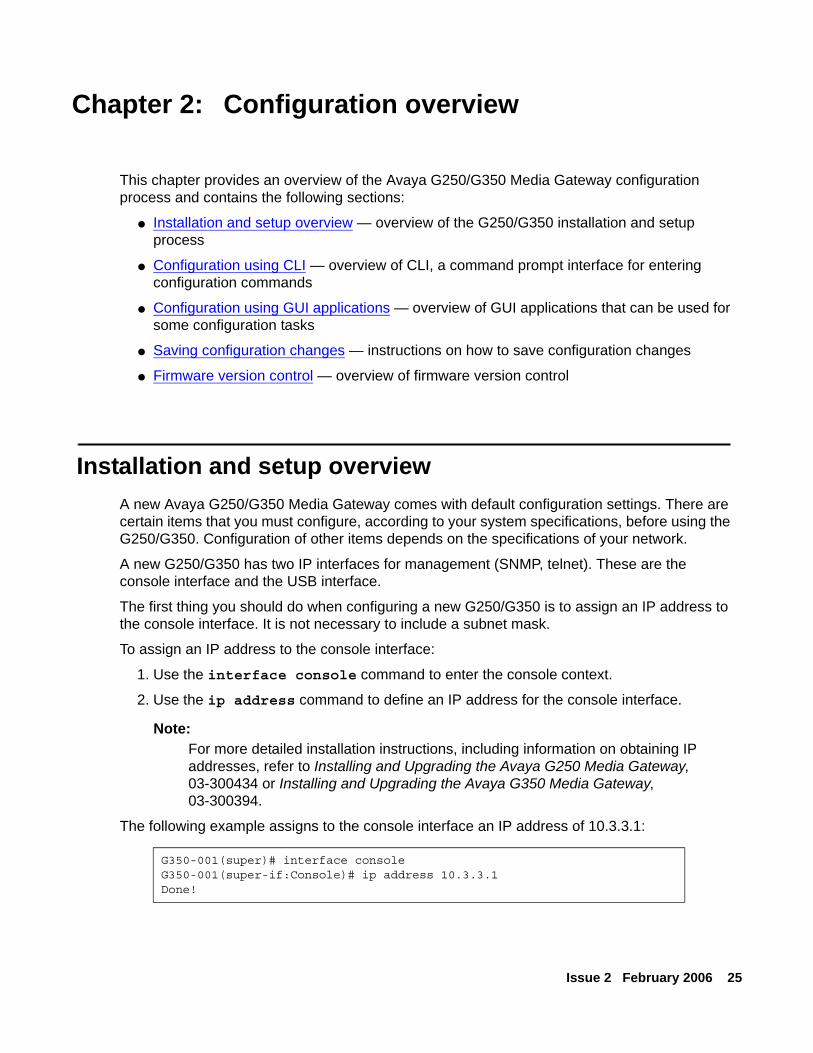
To assign an IP address to the console interface:
1. Use the interface console command to enter the console context.
2. Use the ip address command to define an IP address for the console interface.
Note:Note: For more detailed installation instructions, including information on obtaining IP
addresses, refer to Installing and Upgrading the Avaya G250 Media Gateway, 03-300434 or Installing and Upgrading the Avaya G350 Media Gateway, 03-300394.
The following example assigns to the console interface an IP address of 10.3.3.1:
G350-001(super)# interface consoleG350-001(super-if:Console)# ip address 10.3.3.1Done!
Configuration overview
26 Administration for the Avaya G250 and Avaya G350 Media Gateways
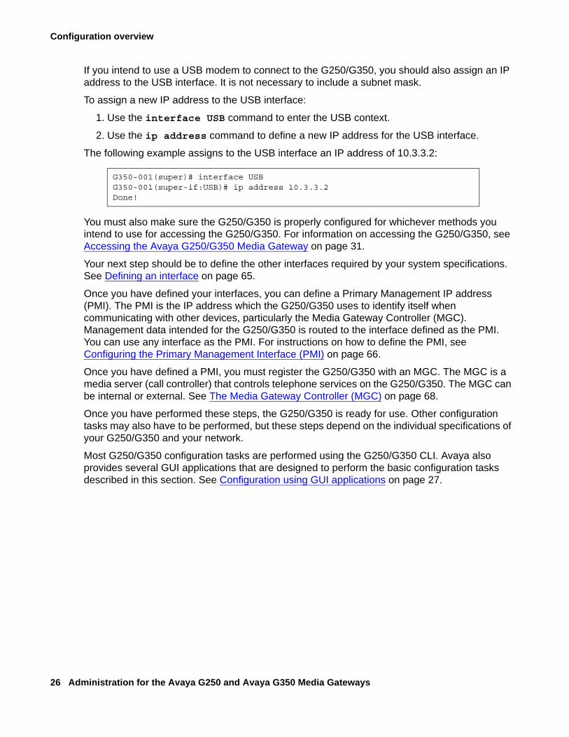
If you intend to use a USB modem to connect to the G250/G350, you should also assign an IP address to the USB interface. It is not necessary to include a subnet mask.
To assign a new IP address to the USB interface:
1. Use the interface USB command to enter the USB context.
2. Use the ip address command to define a new IP address for the USB interface.
The following example assigns to the USB interface an IP address of 10.3.3.2:
You must also make sure the G250/G350 is properly configured for whichever methods you intend to use for accessing the G250/G350. For information on accessing the G250/G350, see Accessing the Avaya G250/G350 Media Gateway on page 31.
Your next step should be to define the other interfaces required by your system specifications. See Defining an interface on page 65.
Once you have defined your interfaces, you can define a Primary Management IP address (PMI). The PMI is the IP address which the G250/G350 uses to identify itself when communicating with other devices, particularly the Media Gateway Controller (MGC). Management data intended for the G250/G350 is routed to the interface defined as the PMI. You can use any interface as the PMI. For instructions on how to define the PMI, see Configuring the Primary Management Interface (PMI) on page 66.
Once you have defined a PMI, you must register the G250/G350 with an MGC. The MGC is a media server (call controller) that controls telephone services on the G250/G350. The MGC can be internal or external. See The Media Gateway Controller (MGC) on page 68.
Once you have performed these steps, the G250/G350 is ready for use. Other configuration tasks may also have to be performed, but these steps depend on the individual specifications of your G250/G350 and your network.
Most G250/G350 configuration tasks are performed using the G250/G350 CLI. Avaya also provides several GUI applications that are designed to perform the basic configuration tasks described in this section. See Configuration using GUI applications on page 27.
G350-001(super)# interface USBG350-001(super-if:USB)# ip address 10.3.3.2Done!
Configuration using CLI
Issue 2 February 2006 27
Configuration using CLIYou can use the Avaya G250/G350 Media Gateway CLI to manage the G250/G350. The CLI is a command prompt interface that enables you to type commands and view responses. For instructions on how to access the G250/G350 CLI, see Accessing the CLI on page 31.
This guide contains information and examples about how to use CLI commands to configure the Avaya G250/G350 Media Gateway. For more information about the G250/G350 CLI and a complete description of each CLI command, see the Avaya G250 and Avaya G350 CLI Reference, 03-300437.
Configuration using GUI applicationsSeveral Avaya GUI applications enable you to perform some configuration tasks on the Avaya G250/G350 Media Gateway. It is recommended to use these applications whenever possible, particularly for initial installation and provisioning.
The Avaya Installation Wizard (Avaya IW) is a web-based installation wizard that leads the user through the key configuration steps of a G250/G350 installation. The Avaya IW can be used for initial configuration of a G250/G350 with an S8300 installed as the G250/G350’s primary (ICC) or backup (LSP) call controller. For instructions on how to access the Avaya IW, see Accessing Avaya IW on page 36. For step-by-step instructions on how to configure the G250/G350 using the Avaya IW, see Installing and Upgrading the Avaya G250 Media Gateway, 03-300434 or Installing and Upgrading the Avaya G350 Media Gateway, 03-300394.
The Gateway Installation Wizard (GIW) is a standalone application that allows the user to perform certain basic G250/G350 configuration tasks. The GIW can be used for initial configuration of a G250/G350 that does not have an S8300 installed as either the G250/G350’s primary (ICC) or backup (LSP) call controller. For instructions on how to access the GIW, see Accessing GIW on page 38. For step-by-step instructions on how to configure the G250/G350 using the GIW, see Installing and Upgrading the Avaya G250 Media Gateway, 03-300434 or Installing and Upgrading the Avaya G350 Media Gateway, 03-300394.
The Avaya Provisioning and Installation Manager (PIM) is an application that allows the user to perform initial installation and provisioning of multiple gateways. It provides integrated network system views that ease centralized configuration tasks, especially provisioning and installing large numbers of gateways simultaneously. One of the primary functions of PIM is to provision and configure Standard Local Survivability (SLS) on the G250. For instructions on how to access PIM, see Accessing PIM on page 40. For instructions on configuring SLS, see Chapter 5: Configuring Standard Local Survivability (SLS) on the G250 on page 87.
Configuration overview
28 Administration for the Avaya G250 and Avaya G350 Media Gateways
You can also use the Avaya G250/G350 Manager to configure most features of the G250/G350. The Avaya G250/G350 Manager is a GUI application. You can access the Avaya G250/G350 Manager from Avaya Integrated Management software or from a web browser. Most of the commands that are available through the G250/G350 CLI are also available through the Avaya G250/G350 Manager. For more information about the Avaya G250/G350 Manager, see the Avaya G250/G350 Manager User Guide, 650-100-709.
Saving configuration changesWhen you make changes to the configuration of the Avaya G250/G350 Media Gateway, you must save your changes to make them permanent. The G250/G350 has two sets of configuration information:
● Running configuration
● Startup configuration
The G250/G350 operates according to the running configuration. When the G250/G350 is reset, the G250/G350 erases the running configuration and loads the startup configuration as the new running configuration. When you change the configuration of the G250/G350, your changes affect only the running configuration. Your changes are lost when the G250/G350 resets if you do not save your changes.
Use the copy running-config startup-config command to save changes to the configuration of the G250/G350. A copy of the running configuration becomes the new startup configuration.
You can back up either the running configuration or the startup configuration to an FTP or TFTP server on your network. You can restore a backup copy of the configuration from the FTP or TFTP server. When you restore the backup copy of the configuration, the backup copy becomes the new running configuration on the G250/G350. For more information, see Managing configuration files on page 85.

Firmware version control
Issue 2 February 2006 29
Firmware version controlFirmware is the software that runs the Avaya G250/G350 Media Gateway. The Avaya G250/G350 Media Gateway has two firmware banks:
● Bank A
● Bank B
Each firmware bank contains a version of the G250/G350 firmware. These may be different versions. The purpose of this feature is to provide redundancy of firmware. You can save an old version of the firmware in case you need to use it later. If it becomes necessary to use the older version, you can reset the G250/G350 using the older version. This is particularly important when uploading new versions.
For more information on firmware version control, see Software and firmware upgrades on page 82.

Configuration overview
30 Administration for the Avaya G250 and Avaya G350 Media Gateways
Issue 2 February 2006 31
Chapter 3: Accessing the Avaya G250/G350 Media Gateway
This chapter provides information about the various ways of accessing the Avaya G250/G350 Media Gateway and contains the following sections:
● Accessing the CLI — instructions on how to access the CLI
● Accessing Avaya IW — instructions on how to access the Avaya IW
● Accessing GIW — instructions on how to access the GIW
● Accessing PIM — instructions on how to access the PIM
● Accessing Avaya Communication Manager — instructions on how to access the Avaya Communication Manager
● Managing login permissions — instructions on using and configuring usernames and passwords, and on configuring the G250/G350 to use SSH, SCP, RADIUS authentication, and the 802.1x protocol
● Special security features — instructions on how to enable and disable the recovery password, establish incoming and outgoing telnet connections, and configure SYN cookies for preventing SYN attacks
Accessing the CLIThis section explains how to access the CLI and includes the following topics:
● CLI Overview — basic instructions on how to use the CLI
● Accessing the CLI locally — instructions on how to access the CLI locally via a local network or a console device
● Accessing the CLI via modem — instructions on how to access the CLI from a remote location using a modem
Accessing the Avaya G250/G350 Media Gateway
32 Administration for the Avaya G250 and Avaya G350 Media Gateways
CLI OverviewThe CLI is a textual command prompt interface that you can use to configure the Avaya G250/G350 Media Gateway and media modules. You can access the CLI with any of the following:
● Telnet through the network
● A console device
● Telnet through dialup:
● Telnet through a serial modem
● Telnet through a USB modem
● Telnet through a USB modem via the S8300
Log in to the CLI with a username and password that your system administrator provides. If your network has a RADIUS server, you can use RADIUS authentication. For more information, see Managing login permissions on page 41.
Note:Note: You can disconnect a telnet session by typing <Ctrl>+]. This is particularly useful
if the normal telnet logout does not work.
CLI contexts
The CLI is divided into various contexts from which sets of related commands can be entered. Contexts are nested in a hierarchy, with each context accessible from another context, called the parent context. The top level of the CLI tree is called the general context. Each command has a context in which the command must be used. You can only use a command in its proper context.
For example, in order to configure the Loopback interface, you must first enter the Loopback interface context from general context. Enter the Loopback interface context using the interface loopback 1 command. Once you are in the Loopback interface context, you can enter Loopback interface commands.
You can use the tree command to view the available commands in each context.
CLI help
You can display a list of commands for the context you are in by typing help or ?. The help command displays a list of all CLI commands that you can use within the current context, with a short explanation of each command.
If you type help or ? before or after the first word or words of a command, the CLI displays a list of all commands in the current context that begin with this word or words. For example, to display a list of IP commands available in general context, type help ip, ip help, ? ip, or ip ?.
Accessing the CLI
Issue 2 February 2006 33
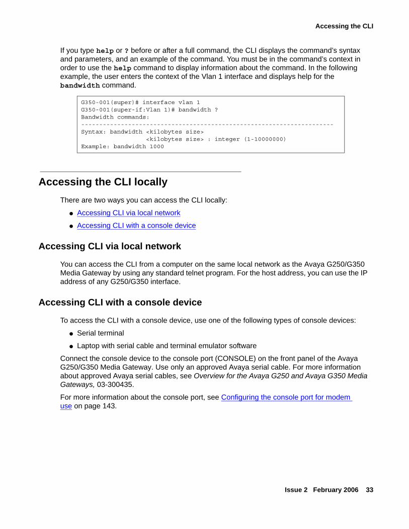
If you type help or ? before or after a full command, the CLI displays the command’s syntax and parameters, and an example of the command. You must be in the command’s context in order to use the help command to display information about the command. In the following example, the user enters the context of the Vlan 1 interface and displays help for the bandwidth command.
Accessing the CLI locallyThere are two ways you can access the CLI locally:
● Accessing CLI via local network
● Accessing CLI with a console device
Accessing CLI via local network
You can access the CLI from a computer on the same local network as the Avaya G250/G350 Media Gateway by using any standard telnet program. For the host address, you can use the IP address of any G250/G350 interface.
Accessing CLI with a console device
To access the CLI with a console device, use one of the following types of console devices:
● Serial terminal
● Laptop with serial cable and terminal emulator software
Connect the console device to the console port (CONSOLE) on the front panel of the Avaya G250/G350 Media Gateway. Use only an approved Avaya serial cable. For more information about approved Avaya serial cables, see Overview for the Avaya G250 and Avaya G350 Media Gateways, 03-300435.
For more information about the console port, see Configuring the console port for modem use on page 143.
G350-001(super)# interface vlan 1G350-001(super-if:Vlan 1)# bandwidth ?Bandwidth commands:----------------------------------------------------------------------Syntax: bandwidth <kilobytes size> <kilobytes size> : integer (1-10000000)Example: bandwidth 1000
Accessing the Avaya G250/G350 Media Gateway
34 Administration for the Avaya G250 and Avaya G350 Media Gateways
Accessing the CLI via modemYou can access the CLI from a remote location using any standard telnet program. Use a dialup PPP network connection from a modem at the remote location. You can connect to either a USB modem connected to the USB port on the front panel of the G250/G350 or a serial modem connected to the console port on the front panel of the G250/G350. Use only an approved Avaya serial cable. For more information about approved Avaya serial cables, see Overview for the Avaya G250 and Avaya G350 Media Gateways, 03-300435.
Note:Note: You can disconnect a telnet session by typing <Ctrl>+]. This is particularly useful
if the normal telnet logout does not work.
Accessing the CLI via a USB modem
To access the CLI with telnet through dialup from a remote location using a USB modem:
1. Connect a modem to the USB port on the front panel of the Avaya G250 or G350 Media Gateway. Use a USB cable to connect the modem. The G250/G350 supports the Multitech MultiModem USB, MT5634ZBA-USB-V92.
2. Make sure the USB port is properly configured for modem use. For details, see Configuring the USB port for modem use on page 141.
3. From the remote computer, create a dialup network connection to the Avaya G250 or G350 Media Gateway. Use the TCP/IP and PPP protocols to create the connection. Configure the connection according to the configuration of the COM port of the remote computer. By default, the G250/G350 uses PAP authentication. If your network has a RADIUS server, you can use RADIUS authentication for the PPP connection. For more information, see Managing login permissions on page 41.
4. Open any standard telnet program on the remote computer.
5. Open a telnet session to the IP address of the USB port on the G250/G350. For instructions on how to set the IP address of the USB port (i.e., the USB interface), see Configuring the USB port for modem use on page 141.
6. Configure the serial connection on the remote computer to match the configuration of the USB port on the G250/G350. The USB port uses the following settings:
● baud —
● data bits — 8
● parity — none
● stop bits — 1
● flow control — hardware
Accessing the CLI
Issue 2 February 2006 35
Accessing the CLI via a serial modem
To access the CLI with telnet through dialup from a remote location using a serial modem:
1. Connect a modem to the console port (CONSOLE) on the front panel of the Avaya G250/G350 Media Gateway. Use an RJ-45 serial cable to connect the modem. The G250/G350 supports the following serial modems:
● Multitech MultiModem ZBA, MT5634ZBA-V92.
● Multitech BRI-NT1 ISDN Modem w/ POTS, MTA128NT, for use in US/Canada.
● Multitech ISDN Modem w/ POTS, MTA128STBRI, for use in Europe and the rest of the world.
The ISDN modems require DB-25 termination as well as the RJ-45 cable.
2. Make sure the console port is properly configured for modem use. For details, see Configuring the console port for modem use on page 143.
3. From the remote computer, create a dialup network connection to the Avaya G250/G350 Media Gateway. Use the TCP/IP and PPP protocols to create the connection. Configure the connection according to the configuration of the COM port of the remote computer. By default, The G250/G350 uses PAP authentication. If your network has a RADIUS server, you can use RADIUS authentication for the PPP connection. For more information, see Managing login permissions on page 41.
4. Open any standard telnet program on the remote computer.
5. Open a telnet session to the IP address of the console port on the G250/G350. For instructions on how to set the IP address of the console port (i.e., the console interface), see Configuring the console port for modem use on page 143.
6. Configure the serial connection on the remote computer to match the configuration of the console port on the G250/G350. The console port uses the following settings:
● baud — highest possible
● data bits — 8
● parity — none
● stop bits — 1
● flow control — hardware
Accessing the Avaya G250/G350 Media Gateway
36 Administration for the Avaya G250 and Avaya G350 Media Gateways
Accessing the CLI via a modem connection to the S8300
If the Avaya G250/G350 Media Gateway includes an S8300 Media Server, you can access the CLI from a remote location by establishing a PPP network connection from a modem at the remote location to a USB modem connected to the one of the USB ports on the front panel of the S8300.
Note:Note: In order to access the CLI via the S8300, the PMI of the G250/G350 must be
configured. See Configuring the Primary Management Interface (PMI) on page 66.
To access the G250/G350 CLI via telnet through a dialup connection from a remote location via the S8300:
1. Connect a USB modem to either of the two USB ports on the Avaya S8300 Media Server. The G250/G350 supports the Multitech MultiModem USB, MT5634ZBA-USB-V92.
2. Use the Avaya Maintenance Web Interface (MWI) to configure the USB port on the S8300 for modem use. For instructions, see Installing and Upgrading the Avaya G250 Media Gateway, 03-300434 or Installing and Upgrading the Avaya G350 Media Gateway, 03-300394.
3. From a remote computer, create a dialup network connection to the S8300. Use the TCP/IP and PPP protocols to create the connection.
4. Open any standard telnet program on the remote computer.
5. Enter the command telnet, followed by the IP address of the S8300 USB port to which the modem is connected.
6. Enter the command telnet, followed by the PMI of the G250/G350.
Accessing Avaya IWThe Avaya Installation Wizard (Avaya IW) is a web-based installation wizard that is used with the Avaya G250/G350 Media Gateway to perform initial configuration tasks and to upgrade software and firmware. The Avaya IW is designed for use with systems that include an S8300 Media Server, operating in either ICC or LSP mode. See The Media Gateway Controller (MGC) on page 68.
Specifically, you can perform the following tasks with the Avaya IW:
● Configure PMI information — see Configuring the Primary Management Interface (PMI) on page 66
● Configure SNMP information — see Configuring SNMP on page 219● Configure Ethernet interfaces — see Configuring Ethernet ports on page 107
Accessing Avaya IW
Issue 2 February 2006 37
● Configure primary and secondary Media Gateway Controllers — see The Media Gateway Controller (MGC) on page 68
● Install license and password files● Install software and firmware upgrades — see Software and firmware upgrades on
page 82● Enable and configure the USB ports of the S8300 for modem use● Enable the G250/G350 for modem use — see Configuring the G250 and G350 for modem
use on page 141● Configure G250/G350 telephony and trunk parameters● Configure alarms● Change your password
When performing initial configuration of the G250/G350, you can access and run the Avaya IW using a laptop computer. To access the Avaya IW:
1. Connect a laptop computer to the Services port of the S8300, using a crossover cable.
2. Make sure the laptop is configured as follows:
● IP Address: 192.11.13.5
● NetMask: 255.255.255.252
● Disable DNS
● Clear the primary WINS and secondary WINS IP Addresses
● Disable the Proxy Server in the Internet Explorer
3. Launch Internet Explorer on the laptop and type the following URL to access the S8300 Media Server Home Page: http://192.11.13.6.
4. Enter the appropriate login name and password.
5. Select the Launch Installation Wizard link from the home page. The Overview screen appears:
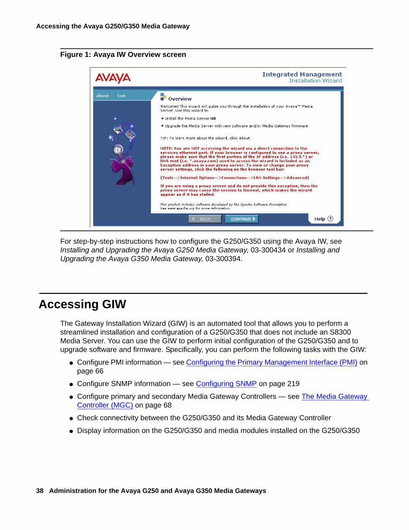
Accessing the Avaya G250/G350 Media Gateway
38 Administration for the Avaya G250 and Avaya G350 Media Gateways
Figure 1: Avaya IW Overview screen
For step-by-step instructions how to configure the G250/G350 using the Avaya IW, see Installing and Upgrading the Avaya G250 Media Gateway, 03-300434 or Installing and Upgrading the Avaya G350 Media Gateway, 03-300394.
Accessing GIWThe Gateway Installation Wizard (GIW) is an automated tool that allows you to perform a streamlined installation and configuration of a G250/G350 that does not include an S8300 Media Server. You can use the GIW to perform initial configuration of the G250/G350 and to upgrade software and firmware. Specifically, you can perform the following tasks with the GIW:
● Configure PMI information — see Configuring the Primary Management Interface (PMI) on page 66
● Configure SNMP information — see Configuring SNMP on page 219
● Configure primary and secondary Media Gateway Controllers — see The Media Gateway Controller (MGC) on page 68
● Check connectivity between the G250/G350 and its Media Gateway Controller
● Display information on the G250/G350 and media modules installed on the G250/G350
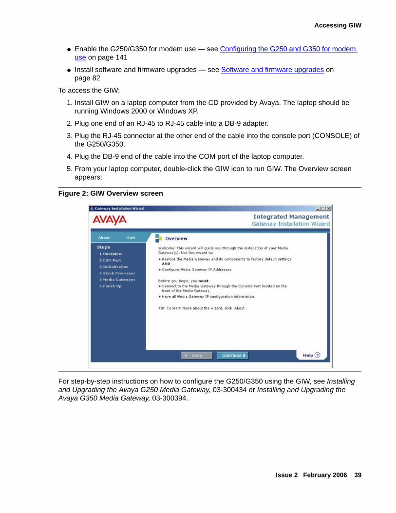
Accessing GIW
Issue 2 February 2006 39
● Enable the G250/G350 for modem use — see Configuring the G250 and G350 for modem use on page 141
● Install software and firmware upgrades — see Software and firmware upgrades on page 82
To access the GIW:
1. Install GIW on a laptop computer from the CD provided by Avaya. The laptop should be running Windows 2000 or Windows XP.
2. Plug one end of an RJ-45 to RJ-45 cable into a DB-9 adapter.
3. Plug the RJ-45 connector at the other end of the cable into the console port (CONSOLE) of the G250/G350.
4. Plug the DB-9 end of the cable into the COM port of the laptop computer.
5. From your laptop computer, double-click the GIW icon to run GIW. The Overview screen appears:
Figure 2: GIW Overview screen
For step-by-step instructions on how to configure the G250/G350 using the GIW, see Installing and Upgrading the Avaya G250 Media Gateway, 03-300434 or Installing and Upgrading the Avaya G350 Media Gateway, 03-300394.
Accessing the Avaya G250/G350 Media Gateway
40 Administration for the Avaya G250 and Avaya G350 Media Gateways
Accessing PIMThe Provisioning and Installation Manager (PIM) provides the capability to remotely configure devices, primarily Avaya media gateways, on a network-wide basis. PIM provides integrated network system views that ease centralized configuration tasks, especially provisioning and installing large numbers of gateways simultaneously.
One of PIM’s primary functions is to provision and configure Standard Local Survivability (SLS) on the G250. See Chapter 5: Configuring Standard Local Survivability (SLS) on the G250 on page 87.
PIM is launched from the Avaya Network Management Console. The Avaya Network Management Console is the central infrastructure application that discovers and monitors enabled network devices and runs Avaya Integrated Management applications.
PIM must be installed on the same Windows server as Avaya Network Management Console with System View and Avaya Secure Access Administration.
For detailed information about installing and launching PIM, see Avaya Integrated Management Enterprise Network Management Installation and Upgrade, 14-300444.
Accessing Avaya Communication ManagerUse Avaya Communication Manager software to control telephone services that the Avaya G250/G350 Media Gateway provides. Avaya Communication Manager software runs on a media server. There might be several media servers on your network that can control the Avaya G250/G350 Media Gateway. You can access Avaya Communication Manager on any media server that is a Media Gateway Controller (MGC) for the Avaya G250/G350 Media Gateway. For more information, see The Media Gateway Controller (MGC) on page 68.
You can access Avaya Communication Manager with any of the following:
● Avaya Site Administration (ASA). ASA provides wizards and other tools that help you to use Avaya Communication Manager effectively. For more information, see Administrator Guide for Avaya Communication Manager, 03-300509.
● Telnet to port 5023 on the MGC, using the following syntax: telnet <IP address of the media server> <5023>. For more information, see Administrator Guide for Avaya Communication Manager, 03-300509.
● Avaya G250/G350 Media Gateway CLI. See Accessing the registered MGC on page 72.
Managing login permissions
Issue 2 February 2006 41
Managing login permissionsThis section explains how to manage login permissions and contains the following topics:
● Security overview — overview of the G250/G350’s internal security mechanism and how it can operate in conjunction with a RADIUS authentication system
● Managing users and passwords — explanation of users, passwords, and access privileges, and instructions on how to define new users
● SSH protocol support — explanation of SSH authentication and instructions on how to configure SSH authentication parameters
● SCP protocol support — explanation of SCP authentication and instructions on how to configure SCP authentication parameters
● RADIUS authentication — instructions on how to configure the G250/G350 to work with an external RADIUS server
● 802.1x protocol — instructions on how to configure 802.1x protocol
Security overviewThe Avaya G250/G350 Media Gateway includes a security mechanism through which the system administrator defines users and assigns each user and username and a password. Each user is assigned a privilege level. The user’s privilege level determines which commands the user can perform.
In addition to its basic security mechanism, the G250/G350 supports secure data transfer via SSH and SCP.
The G250/G350 can be configured to work with an external RADIUS server to provide user authentication. When RADIUS authentication is enabled on the G250/G350, the RADIUS server operates in conjunction with the G250/G350 security mechanism. When the user enters a username, the G250/G350 first searches its own database for the username. If the G250/G350 does not find the username in its own database, it establishes a connection with the RADIUS server, and the RADIUS server provides the necessary authentication services.
The G250/G350 also uses the 802.1x protocol in conjunction with EAP within EAPOL and over RADIUS to provide a means for authenticating and authorizing users attached to a LAN port, and for preventing access to that port in cases where the authentication process fails.
Accessing the Avaya G250/G350 Media Gateway
42 Administration for the Avaya G250 and Avaya G350 Media Gateways
Managing users and passwordsYou must provide a username and password when you perform any of the following actions:
● When you access the CLI. For more information, see Accessing the CLI on page 31.
● When you connect a modem with dialup PPP. For more information, see Accessing the CLI via modem on page 34.
● When you open Avaya G350 Manager.
When you use Avaya G350 Manager or the CLI, your username determines your privilege level. The commands that are available to you during the session depend on your privilege level.
If your network has a RADIUS server, you can use RADIUS authentication instead of a username and password. A RADIUS server provides centralized authentication service for many devices on a network. For more information, see RADIUS authentication on page 45.
Privilege level
When you start to use Avaya G350 Manager or the CLI, you must enter a username. The username that you enter sets your privilege level. The commands that are available to you during the session depend on your privilege level. If you use RADIUS authentication, the RADIUS server sets your privilege level.
The G250/G350 provides the following three privilege levels:
● Read-only — You can use Read-only privilege level to view configuration parameters.
● Read-write — You can use Read-write privilege level to view and change all configuration parameters except those related to security. For example, you cannot change a password with Read-write privilege level.
● Admin — You can use Admin privilege level to view and change all configuration parameters, including parameters related to security. Use Admin privilege level only when you need to change configuration that is related to security, such as adding new user accounts and setting the device policy manager source.
The default username has Admin privilege level. For security reasons, the network administrator usually changes the password of the default username. For more information about privilege levels, see Avaya G250 and Avaya G350 CLI Reference, 03-300437.
Configuring usernames
To create a username, use the username command. To remove a username, use the no username command. To change the password or the privilege level for a username, remove the username and add it again. You need an Admin privilege level to use the username and no username commands.
Managing login permissions
Issue 2 February 2006 43
When you create a new user, you must define the user’s password and privilege level. The following example creates a user named John with the password johnny69 and a Read-write privilege level:
SSH protocol supportSecure Shell (SSH) protocol is a security protocol that enables you to establish a remote session over a secured tunnel, also called a remote shell. SSH accomplishes this by creating a transparent, encrypted channel between the local and remote devices. In addition to the remote shell, SSH provides secure file transfer between the local and remote devices. SSH is used for telnet file transfers. The G250/G350 supports two concurrent SSH users.
There are two ways to establish an SSH session:
● RSA authentication
● Password authentication
Use the show ip ssh command to determine which of these ways is used on your G250/G350. See SSH Configuration on page 44.
RSA authentication works as follows:
● The G250/G350 generates a key of variable length (512-2048 bits) using the DSA encryption method. This is the private key.
● The G250/G350 calculates an MD5 Hash of the private key, called a fingerprint (the public key). The fingerprint is always 16 bytes long. This fingerprint is displayed.
● The G250/G350 sends the public key (the fingerprint) to the client computer. This public key is used by the client to encrypt the data it sends to the G250/G350. The G250/G350 decrypts the data using the private key.
● Both sides negotiate and must agree on the same chipper type. The G250/G350 only supports 3DES-CBC encryption. The user on the client side accepts the fingerprint. The client maintains a cache containing a list of fingerprints per server IP address. If the information in this cache changes, the client notifies the user.
● The client chooses a random number that is used to encrypt and decrypt the information sent.
● This random number is sent to the G250/G350, after encryption based on the G250/G350’s public key.
● When the G250/G350 receives the encrypted random number, it decrypts it using the private key. This random number is now used with the 3DES-CBC encryption method for all encryption and decryption of data. The public and private keys are no longer used.
G350-001(super)# username john password johnny69 access-type read-write
Accessing the Avaya G250/G350 Media Gateway
44 Administration for the Avaya G250 and Avaya G350 Media Gateways
Password authentication works as follows:
● Before any data is transferred, the G250/G350 requires the client to supply a user name and password. This authenticates the user on the client side to the G250/G350.
SSH Configuration
Use the ip ssh command to enable SSH authentication. Use the no form of this command to disable the SSH server. Disabling the server disconnects all active SSH sessions. By default, SSH is enabled.
Use the crypto key generate dsa command to generate an SSH host key pair.
Use the show ip ssh command to display SSH configuration information and information about any active SSH sessions.
Use the disconnect ssh command to disconnect an existing SSH session.
SCP protocol supportIn addition to data transfer via an SSH session, the SSH protocol is used to support SCP for secure file transfer. When using SCP, the G250/G350 is the client, and an SCP server must be installed on the management station. After users are defined on the SCP server, the G250/G350 acts as an SCP client.
The process of establishing an SCP session is the same process as described in SSH protocol support on page 43, except that the roles of the G250/G350 and the client computer are reversed.
To perform file transfers secured by SCP, the G250/G350 launches a local SSH client via the CLI. This establishes a secured channel to the secured file server. The G250/G350 authenticates itself to the server by providing a user name and password. With a Windows-based SSH server (WinSSHD), the user name provided must be a defined user on the Windows machine with read/write privileges. The files transferred via SCP are saved in the C:\Documents and Settings\username directory.
Use the clear ssh-client known-hosts command to clear the client’s list of SCP server fingerprints. Each SCP client maintains a list of server fingerprints. If a key changes, the client’s verification of the server’s fingerprint will fail, thereby preventing the client’s access to the SCP server. If this happens, you can use the clear ssh-client known-hosts command to erase the client’s server fingerprint list. This enables the client to access the server and begin to recreate its list of fingerprints with the SCP server’s new fingerprint.
The network element performs file transfer in unattended mode.
Managing login permissions
Issue 2 February 2006 45
RADIUS authenticationIf your network has a RADIUS server, you can configure the G250/G350 to use RADIUS authentication. A RADIUS server provides centralized authentication service for many devices on a network. When you use RADIUS authentication, you do not need to configure usernames and passwords on the G250/G350. When you try to access the G250/G350, the G250/G350 searches for your username and password in its own database first. If it does not find them, it activates RADIUS authentication.
To use RADIUS authentication:
1. Configure your RADIUS server with the usernames, passwords, and privilege levels that you want to use on the G250/G350.
2. Configure RADIUS authentication on the G250/G350, as described below.
Use the following commands to configure RADIUS authentication on the G250/G350. For more information about these commands, see the Avaya G250 and Avaya G350 CLI Reference, 03-300437.
1. Use the set radius authentication enable command to enable RADIUS authentication.
2. Use the set radius authentication secret command to set the shared secret for the authentication. This command must be followed by a text string. For example:
set radius authentication secret hush
3. Use the set radius authentication server command to set the IP address of the primary or secondary RADIUS Authentication server.
You can use the following commands to change the RADIUS parameters. These commands are optional.
● Use the set radius authentication retry-number command to set the number of times to resend an access request when there is no response.
● Use the set radius authentication retry-time command to set the time to wait before resending an access request.
● Use the set radius authentication udp-port command to set the RFC 2138 approved UDP port number. Normally, the UDP port number should be set to its default value of 1812. Some early implementations of the RADIUS server used port number 1645.
To disable RADIUS authentication on the G250/G350, use the set radius authentication disable command.
To display the RADIUS parameters, use the show radius authentication command. Shared secrets are not displayed.
For additional information on RADIUS configuration and authentication, go to the Avaya web site at http://www.avaya.com/support, and perform a search for the document Avaya G700/G350 RADIUS Configuration Overview.
Accessing the Avaya G250/G350 Media Gateway
46 Administration for the Avaya G250 and Avaya G350 Media Gateways
802.1x protocolThe 802.1x protocol is a method for performing authentication to obtain access to the G250/G350’s LAN ports. 802.1x provides a means of authenticating and authorizing users attached to a LAN port and of preventing access to that port in cases where the authentication process fails. On the G350, you can enable 802.1x on the MM314 and MM316 media modules’ 10/100 Ethernet ports. On the G250, you can enable 802.1x on the eight Ethernet LAN PoE ports located on the G250’s front panel.
Note:Note: You cannot enable 802.1x on the MM314/MM316 media modules’ Gigabit
Ethernet port (port 51). Also, 802.1x is not available on the G250-DCP.
The 802.1x protocol defines an interaction between the following three entities:
● Supplicant — an entity (the host) at one end of a point-to-point LAN segment that is requesting authentication
● Authenticator — an entity (in this case the G250/G350) at the other end of a point-to-point LAN segment that facilitates authentication of the Supplicant
● Authentication (RADIUS) Server — an entity that provides an authentication service to the Authenticator. The Authentication Server determines, from the credentials provided by the Supplicant, whether the Supplicant is authorized to access the services provided by the Authenticator.
The 802.1x application complies with the existing IEEE Port Based Network Control standard to perform its authentication operation. Specifically, it makes use of Extensible Authentication Protocol (EAP) messages encapsulated within Ethernet frames (EAPOL), and EAP over RADIUS for the communication between the Authenticator and the Authentication Server.
Note:Note: The G250/G350 supports the following EAP types: MD5, PEAP, TTLS, and TLS.
Authentication Modes
There are two available authentication modes:
● Port-based — the authentication mode defined by the 802.1x standard. This mode requires that each 10/100 802.1x-enabled port be connected directly to a single 802.1x Supplicant, so security will be maintained. If more clients are connected to that port, the first authenticated client opens the port and all other clients are able to enter the network without the need for authentication.
Port-based mode is the default mode and it is backward compatible with the 802.1x implementation in previous releases.
This mode is also known as Single Supplicant mode.
Managing login permissions
Issue 2 February 2006 47
● MAC-based — an extension to the 802.1x standard. In this mode, multiple Supplicants are connected to an 802.1x-enabled port via an external repeater/hub. Authentication is performed per MAC address.
The main application for the MAC-based mode is to allow the connection of an Avaya IP phone and a PC which are connected to the same gateway port and support the 802.1x application. In previous releases, this case could not be supported because in port-based mode the gateway authenticates the port and not the stations connected to it. Thus, connecting two supplicants to the same port in port-base mode could confuse the gateway.
This mode is also known as Multi Supplicant mode.
Note:Note: It is highly recommended to configure all ports in MAC-based mode.
How port based authentication worksThe authentication procedure is port-based, which means:
● Access control is achieved by enforcing authentication on connected ports.
● If an endpoint station that connects to a port is not authorized, the port state is set to “unauthorized”, which closes the port to all traffic.
● As a result of an authentication attempt, the port can be either in a “blocked” or a “forwarding” state. Since the spanning-tree application also controls the same forwarding state of the port, the actual forwarding state of the port is the combination of the decisions made by the two applications; e.g., if 802.1x or STA put the port into a “blocked” state, the port is in a “blocked” state.
How MAC-based authentication worksIn this mode, the port is always in a forwarding state, assuming STA doesn't block the port. However, the G350 monitors the ingress/egress packets and only those originating from or routed to the authenticated device are forwarded. If the device is not authenticated, the gateway initiates authentication with the device. All unauthenticated device packets are discarded. During this time, all authenticated supplicants can send and receive packets from the port.
The G250 behaves a little differently. The G250 controls only the egress packets, i.e., until the device authenticates the port, all packets from the network to the device are blocked.
Configuring 802.1x
On the G350, you can configure 802.1x on the MM314 and MM316 10M/100M ports. Neither the LAN and WAN port on the chassis nor the uplink port in the MM314 (10/100/1G copper) and MM316 (10/100/1G copper) media modules support 802.1x.
On the G250, you can enable 802.1x on the eight Ethernet LAN PoE ports located on the G250’s front panel. 802.1x is not supported on the G250-DCP model.
Accessing the Avaya G250/G350 Media Gateway
48 Administration for the Avaya G250 and Avaya G350 Media Gateways
To configure 802.1x:
1. Configure RADIUS authentication on the G250/G350. For instructions, see RADIUS authentication on page 45.
2. Use the set port dot1x port-control command to change the 802.1x mode of an individual port. This command must be followed by the module and port number, and the 802.1x mode. The following are the possible modes:
- force-unauthorize — the port is always blocked
- auto — whether the port is blocked or open depends on the authentication outcome
- force-authorize — the port is always open (in forwarding state)
By default, all ports are in auto mode. In other words, all ports are configured to use 802.1x authentication if it is enabled on the G250/G350. If a port is not in auto mode, you can use the following command to return the port to auto mode:
3. Use the set port dot1x port-control command to configure the authentication mode of the LAN port connected to the RADIUS server as force-authorize. This ensures that the port remains open at all times, so that it will be able to transmit authentication requests to the RADIUS server. For example, if port 5 is the port that connects to the RADIUS server, type the following command:
4. Use the set dot1x system-auth-control enable command to enable 802.1x authentication on all ports set to auto mode. For example:
To disable 802.1x authentication on the G250/G350, use the command set dot1x system-auth-control disable.
G250-001(super)# set port dot1x port-control 10/4 autoDone !G250-001(super)#
G350-001(super)# set port dot1x port-control 6/3 autoDone !G350-001(super)#
G250-001(super)# set port dot1x port-control 10/5 force-authorizeDone !G250-001(super)#
G350-001(super)# set port dot1x port-control 6/5 force-authorizeDone !G350-001(super)#
G350-001(super)# set dot1x system-auth-control enable
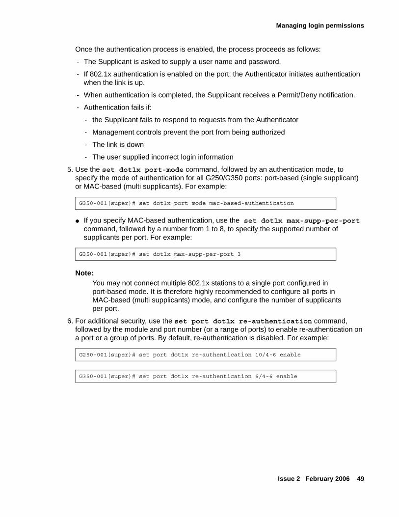
Managing login permissions
Issue 2 February 2006 49
Once the authentication process is enabled, the process proceeds as follows:
- The Supplicant is asked to supply a user name and password.
- If 802.1x authentication is enabled on the port, the Authenticator initiates authentication when the link is up.
- When authentication is completed, the Supplicant receives a Permit/Deny notification.
- Authentication fails if:
- the Supplicant fails to respond to requests from the Authenticator
- Management controls prevent the port from being authorized
- The link is down
- The user supplied incorrect login information
5. Use the set dot1x port-mode command, followed by an authentication mode, to specify the mode of authentication for all G250/G350 ports: port-based (single supplicant) or MAC-based (multi supplicants). For example:
● If you specify MAC-based authentication, use the set dot1x max-supp-per-port command, followed by a number from 1 to 8, to specify the supported number of supplicants per port. For example:
Note:Note: You may not connect multiple 802.1x stations to a single port configured in
port-based mode. It is therefore highly recommended to configure all ports in MAC-based (multi supplicants) mode, and configure the number of supplicants per port.
6. For additional security, use the set port dot1x re-authentication command, followed by the module and port number (or a range of ports) to enable re-authentication on a port or a group of ports. By default, re-authentication is disabled. For example:
G350-001(super)# set dot1x port mode mac-based-authentication
G350-001(super)# set dot1x max-supp-per-port 3
G250-001(super)# set port dot1x re-authentication 10/4-6 enable
G350-001(super)# set port dot1x re-authentication 6/4-6 enable
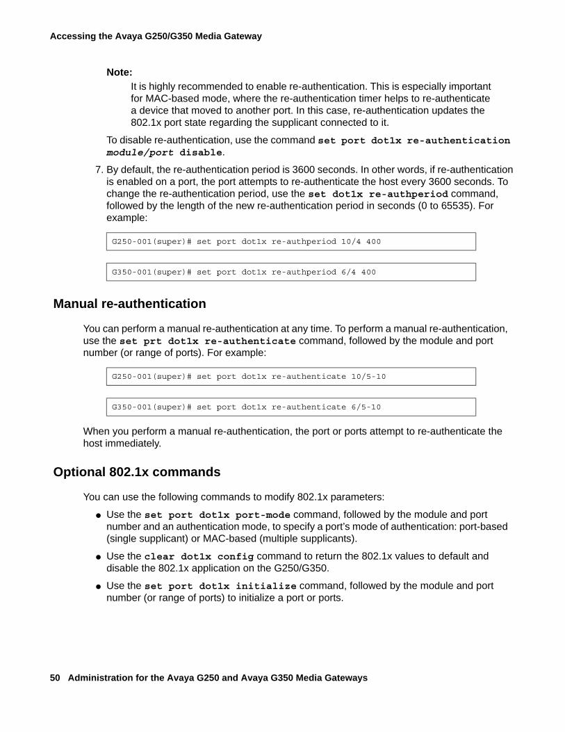
Accessing the Avaya G250/G350 Media Gateway
50 Administration for the Avaya G250 and Avaya G350 Media Gateways
Note:Note: It is highly recommended to enable re-authentication. This is especially important
for MAC-based mode, where the re-authentication timer helps to re-authenticate a device that moved to another port. In this case, re-authentication updates the 802.1x port state regarding the supplicant connected to it.
To disable re-authentication, use the command set port dot1x re-authentication module/port disable.
7. By default, the re-authentication period is 3600 seconds. In other words, if re-authentication is enabled on a port, the port attempts to re-authenticate the host every 3600 seconds. To change the re-authentication period, use the set dot1x re-authperiod command, followed by the length of the new re-authentication period in seconds (0 to 65535). For example:
Manual re-authentication
You can perform a manual re-authentication at any time. To perform a manual re-authentication, use the set prt dot1x re-authenticate command, followed by the module and port number (or range of ports). For example:
When you perform a manual re-authentication, the port or ports attempt to re-authenticate the host immediately.
Optional 802.1x commands
You can use the following commands to modify 802.1x parameters:
● Use the set port dot1x port-mode command, followed by the module and port number and an authentication mode, to specify a port’s mode of authentication: port-based (single supplicant) or MAC-based (multiple supplicants).
● Use the clear dot1x config command to return the 802.1x values to default and disable the 802.1x application on the G250/G350.
● Use the set port dot1x initialize command, followed by the module and port number (or range of ports) to initialize a port or ports.
G250-001(super)# set port dot1x re-authperiod 10/4 400
G350-001(super)# set port dot1x re-authperiod 6/4 400
G250-001(super)# set port dot1x re-authenticate 10/5-10
G350-001(super)# set port dot1x re-authenticate 6/5-10
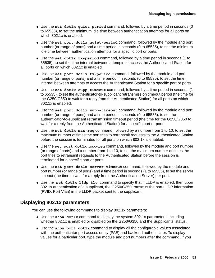
Managing login permissions
Issue 2 February 2006 51
● Use the set dot1x quiet-period command, followed by a time period in seconds (0 to 65535), to set the minimum idle time between authentication attempts for all ports on which 802.1x is enabled.
● Use the set port dot1x quiet-period command, followed by the module and port number (or range of ports) and a time period in seconds (0 to 65535), to set the minimum idle time between authentication attempts for a specific port or ports.
● Use the set dot1x tx-period command, followed by a time period in seconds (1 to 65535), to set the time internal between attempts to access the Authenticated Station for all ports on which 802.1x is enabled.
● Use the set port dot1x tx-period command, followed by the module and port number (or range of ports) and a time period in seconds (0 to 65535), to set the time internal between attempts to access the Authenticated Station for a specific port or ports.
● Use the set dot1x supp-timeout command, followed by a time period in seconds (1 to 65535), to set the authenticator-to-supplicant retransmission timeout period (the time for the G250/G350 to wait for a reply from the Authenticated Station) for all ports on which 802.1x is enabled.
● Use the set port dot1x supp-timeout command, followed by the module and port number (or range of ports) and a time period in seconds (0 to 65535), to set the authenticator-to-supplicant retransmission timeout period (the time for the G250/G350 to wait for a reply from the Authenticated Station) for a specific port or ports.
● Use the set dot1x max-req command, followed by a number from 1 to 10, to set the maximum number of times the port tries to retransmit requests to the Authenticated Station before the session is terminated for all ports on which 802.1x is enabled.
● Use the set port dot1x max-req command, followed by the module and port number (or range of ports) and a number from 1 to 10, to set the maximum number of times the port tries to retransmit requests to the Authenticated Station before the session is terminated for a specific port or ports.
● Use the set port dot1x server-timeout command, followed by the module and port number (or range of ports) and a time period in seconds (1 to 65535), to set the server timeout (the time to wait for a reply from the Authentication Server) per port.
● Use the set dot1x lldp tlv command to specify that if LLDP is enabled, then upon 802.1x authentication of a supplicant, the G250/G350 transmits the port LLDP information (PVID, Port Vlan) in the LLDP packet sent to the supplicant.
Displaying 802.1x parametersYou can use the following commands to display 802.1x parameters:
● Use the show dot1x command to display the system 802.1x parameters, including whether 802.1x is enabled or disabled on the G250/G350 and the Supplicants’ status.
● Use the show port dot1x command to display all the configurable values associated with the authenticator port access entity (PAE) and backend authenticator. To display values for a particular port, type the module and port numbers after the command. If you
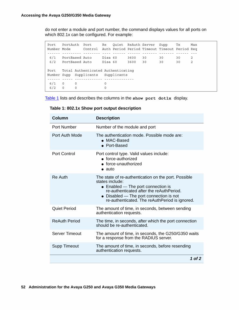
Accessing the Avaya G250/G350 Media Gateway
52 Administration for the Avaya G250 and Avaya G350 Media Gateways
do not enter a module and port number, the command displays values for all ports on which 802.1x can be configured. For example:
Table 1 lists and describes the columns in the show port dot1x display.
Port PortAuth Port Re Quiet ReAuth Server Supp Tx MaxNumber Mode Control Auth Period Period Timeout Timeout Period Req------ --------- -------- ---- ------ ------ ------- ------- ------ --- 6/1 PortBased Auto Disa 60 3600 30 30 30 2 6/2 PortBased Auto Disa 60 3600 30 30 30 2
Port Total Authenticated AuthenticatingNumber Supp Supplicants Supplicants------ ----- ------------- -------------- 6/1 0 0 0 6/2 0 0 0
Table 1: 802.1x Show port output description
Column Description
Port Number Number of the module and port
Port Auth Mode The authentication mode. Possible mode are: ● MAC-Based● Port-Based
Port Control Port control type. Valid values include:● force-authorized● force-unauthorized● auto
Re Auth The state of re-authentication on the port. Possible states include:
● Enabled — The port connection is re-authenticated after the reAuthPeriod.
● Disabled — The port connection is not re-authenticated. The reAuthPeriod is ignored.
Quiet Period The amount of time, in seconds, between sending authentication requests.
ReAuth Period The time, in seconds, after which the port connection should be re-authenticated.
Server Timeout The amount of time, in seconds, the G250/G350 waits for a response from the RADIUS server.
Supp Timeout The amount of time, in seconds, before resending authentication requests.
1 of 2
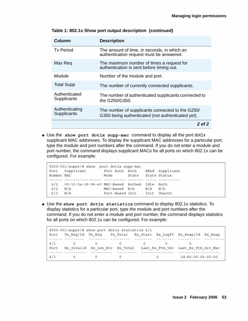
Managing login permissions
Issue 2 February 2006 53
● Use the show port dot1x supp-mac command to display all the port dot1x supplicant MAC addresses. To display the supplicant MAC addresses for a particular port, type the module and port numbers after the command. If you do not enter a module and port number, the command displays supplicant MACs for all ports on which 802.1x can be configured. For example:
● Use the show port dot1x statistics command to display 802.1x statistics. To display statistics for a particular port, type the module and port numbers after the command. If you do not enter a module and port number, the command displays statistics for all ports on which 802.1x can be configured. For example:
Tx Period The amount of time, in seconds, in which an authentication request must be answered.
Max Req The maximum number of times a request for authentication is sent before timing out.
Module Number of the module and port.
Total Supp The number of currently connected supplicants.
Authenticated Supplicants
The number of authenticated supplicants connected to the G250/G350.
Authenticating Supplicants
The number of supplicants connected to the G250/G350 being authenticated (not authenticated yet).
G350-001(super)# show port dot1x supp-macPort Supplicant Port Auth Auth BEnd SupplicantNumber MAC Mode State State Status------ ----------------- ---------- ------- ----- ---------- 6/1 00-10-5a-18-94-e3 MAC-Based Authed Idle Auth 6/2 N/A MAC-Based N/A N/A N/A 6/3 N/A Port-Based Init Init Unauth
G350-001(super)# show port dot1x statistics 6/1Port Tx_Req/Id Tx_Req Tx_Total Rx_Start Rx_Logff Rx_Resp/Id Rx_Resp------ --------- -------- --------- -------- -------- ---------- ---------6/1 2 5 0 0 0 0Port Rx_Invalid Rx_Len_Err Rx_Total Last_Rx_Frm_Ver Last_Rx_Frm_Src_Mac------ ---------- ---------- --------- --------------- -------------------6/1 0 0 0 0 1d-80-00-00-00-00
Table 1: 802.1x Show port output description (continued)
Column Description
2 of 2
Accessing the Avaya G250/G350 Media Gateway
54 Administration for the Avaya G250 and Avaya G350 Media Gateways
Special security featuresThis section describes the following special security features:
● Enabling and disabling recovery password — instructions on how to enable and disable the recovery password, which provides emergency access to the G250/G350 via a direct connection to the console port
● Enabling and disabling telnet access — instructions on how to enable and disable telnet access to and from the G250/G350
● Enabling SYN cookies — instructions on how to enable SYN cookies for preventing SYN attacks on the G250/G350
● Managed Security Services (MSS) — describes the reporting of suspected DoS attacks to Avaya Security Operations Center (SOC)
Enabling and disabling recovery passwordThe G250/G350 includes a special recovery password. The purpose of the recovery password is to enable the system administrator to access the G250/G350 in the event that the regular password is forgotten. You can only use the recovery password when accessing the G250/G350 via a direct connection to the console port. See Accessing CLI with a console device on page 33.
You can use the set terminal recovery password command to enable or disable the recovery password. You can only use this command when accessing the G250/G350 via a direct connection to the console port.
Enabling and disabling telnet accessYou can enable and disable the G250/G350’s ability to establish incoming and outgoing telnet connections, using the following commands. You can only use these commands when accessing the G250/G350 via a direct connection to the console port. See Accessing CLI with a console device on page 33.
● Use the ip telnet command to enable the G250/G350 to establish an incoming telnet connection. Use the no form of this command to disable the G250/G350’s ability to establish an incoming telnet connection.
● Use the ip telnet-client command to enable the G250/G350 to establish an outgoing telnet connection. Use the no form of this command to disable the G250/G350’s ability to establish an outgoing telnet connection.
Special security features
Issue 2 February 2006 55
Enabling SYN cookiesThis section describes how SYN cookies provide protection against SYN attacks, and how to enable SYN cookies, and includes the following topics:
● Overview of SYN cookies — describes SYN attacks and how SYN cookies protect from SYN attacks
● Configuring SYN cookies — instructions on how to configure SYN cookies
● Maintaining SYN cookies — instructions on how to display and clear SYN cookies statistics
Overview of SYN cookies
The G250/G350 provides various TCP/IP services and is therefore exposed to a myriad of TCP/IP based DoS attacks.DoS (Denial of Service) attacks refers to a wide range of malicious attacks that can cause a denial of one or more services provided by a targeted host. Specifically, a SYN attack is a well-known TCP/IP attack in which a malicious attacker targets a vulnerable device and effectively denies it from establishing new TCP connections.SYN cookies refers to a well-known method of protection against a SYN attack.
SYN attack (SYN flood attack)The SYN (TCP connection request) attack is a common DoS attack characterized by the following pattern: Using a spoofed IP address, an attacker sends multiple SYN packets to a listening TCP port on the target machine (the victim). For each SYN packet received, the target machine allocates resources and sends an acknowledgement (SYN-ACK) to the source IP address. The TCP connection is called a “half-open” connection at this point since the initiating side did not yet send back an acknowledgment (termed the 3rd ACK).Because the target machine does not receive a response from the attacking machine, it attempts to resend the SYN-ACK, typically five times, at 3-, 6-, 12-, 24-, and 48-second intervals, before de-allocating the resources 96 seconds after attempting the last retry. Altogether, the target machine typically allocates resources for over three minutes to respond to a single SYN attack.When an attacker uses this technique repeatedly, the target machine eventually runs out of memory resources since it holds numerous half-open connections. It is unable to handle any more connections, thereby denying service to legitimate users.Moreover, flooding the victim with TCP SYN at a high rate can cause the internal queues to fill up, also causing a denial of service.
Accessing the Avaya G250/G350 Media Gateway
56 Administration for the Avaya G250 and Avaya G350 Media Gateways
SYN cookiesSYN cookies protect against SYN attacks by employing the following strategies:
● Not maintaining any state at all for half-open inbound TCP sessions, thus preventing the SYN attack from depleting memory resources.
SYN cookies are able to maintain no state for half-open connections by responding to SYN requests with a SYN-ACK that contains a specially crafted initial sequence number (ISN), called a cookie. The value of the cookie is not a pseudo-random number generated by the system but is instead the result of a hash function. The hash result is generated from the source IP, source port, destination IP, destination port, and some secret values. The cookie can be verified when receiving a valid 3rd ACK that establishes the connection. The verification ensures that the connection is a legitimate connection and that the source IP address was not spoofed.
● Employing the SYN cookies method at a lower point in the network stack then regular TCP handling, closer to the start point of packet handling. This reduces the chances that a SYN attack will fill up the internal queues.
● Performing SYN attack fingerprinting and alerting an administrator about a SYN attack as it occurs. This is implemented by keeping track of the rate at which half-open TCP connections are created, and sending an alert when the rate exceeds a certain threshold.
In addition, when the SYN cookies mechanism is active, a hostile port scan might be fooled into thinking all TCP ports are open.
Configuring SYN cookies
To configure SYN cookies on the G250/G350:
1. Type the tcp syn-cookies command.
2. Copy the running configuration to the start-up configuration using the copy running-config startup-config command.
3. Reset the device using the reset command.
SYN cookies are now enabled on the device.
SYN attack notificationWhen the SYN cookies feature is enabled, the G250/G350 alerts the administrator to a suspected SYN attack as it occurs by sending the following syslog message:
SYN attack suspected! Number of unanswered SYN requests is greater than 20 in last 10 seconds.
Special security features
Issue 2 February 2006 57
Maintaining SYN cookies
You can use the following commands to show and clear SYN cookies statistics:
● Use the show tcp syn-cookies command to show SYN cookies statistics.
Note:Note: For an example and explanation of SYN cookies statistics, see Avaya G250 and
Avaya G350 CLI Reference, 03-300437.
● Use the clear tcp syn-cookies counters command to clear the SYN cookies counters.
Managed Security Services (MSS)Media Gateway IP interfaces and gateway applications such as WAN routers, PoE switches, and VPN devices can be at risk for Denial of Service (DoS) attacks. The G250/G350 identifies predefined or custom-defined traffic patterns as suspected DoS attacks and generates SNMP notifications, referred to as Managed Security Services (MSS) notifications.
This section includes the following topics:
● MSS reporting mechanism
● Configuring MSS
● DoS attack classifications
● Defining custom DoS classifications
● CLI commands
● Example
MSS reporting mechanism
MSS notifications are sent to the active MGC by the dynamic trap manager. MSS notifications sent to the active MGC by the dynamic trap manager are converted to syslog messages by the SNMP trap manager on the MGC. For general information about configuring and enabling syslog messages and syslog message format, refer to Configuring a Syslog server on page 120.
MSS notifications are intercepted and, if certain conditions are met, may be forwarded to the Avaya Security Operations Center (SOC) as INADS alarms. The SOC is an Avaya service group that handles DoS alerts, responding as necessary to any DoS attack or related security issue.
Accessing the Avaya G250/G350 Media Gateway
58 Administration for the Avaya G250 and Avaya G350 Media Gateways
Note:Note: The syslog messages on the active MGC are stored in the messages file on the
MGC hard disk. You can view the syslog messages through the Avaya Maintenance Web Interface (MWI) if you want to debug security issues directly. For information about how to view syslog messages, see Viewing QoS traps, QoS fault traps, and QoS clear traps on page 282.
Note:Note: Any additional SNMP recipients defined with the security notification group
enabled also receive the MSS notifications.
Configuring MSS
The MSS feature is automatically enabled and monitors all IP interfaces, including WAN data interfaces, IPSEC tunnels, Ethernet LAN and WAN ports, VoIP engine interfaces, and Dialer and serial PPP interfaces. The MSS reporting rate is configurable.
To configure MSS notifications:
1. Make sure that the dynamic trap manager, which automatically sets the IP address of the active MGC SNMP trap manager, is configured so that security notifications are sent to the active MGC. By default, all types of notifications are enabled. You can use the show snmp command to check which notification groups are configured to be sent to the active MGC. You can modify the dynamic trap manager configuration using the snmp-server dynamic-trap-manager command, setting the notification type to all or security.
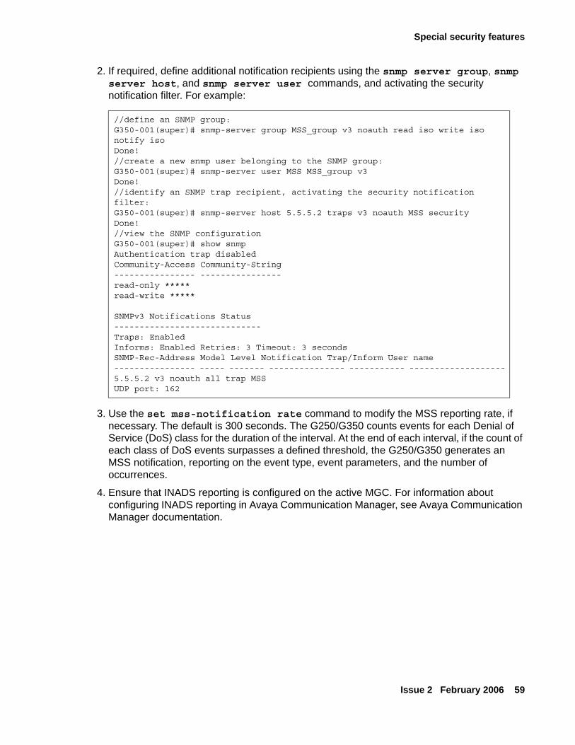
Special security features
Issue 2 February 2006 59
2. If required, define additional notification recipients using the snmp server group, snmp server host, and snmp server user commands, and activating the security notification filter. For example:
3. Use the set mss-notification rate command to modify the MSS reporting rate, if necessary. The default is 300 seconds. The G250/G350 counts events for each Denial of Service (DoS) class for the duration of the interval. At the end of each interval, if the count of each class of DoS events surpasses a defined threshold, the G250/G350 generates an MSS notification, reporting on the event type, event parameters, and the number of occurrences.
4. Ensure that INADS reporting is configured on the active MGC. For information about configuring INADS reporting in Avaya Communication Manager, see Avaya Communication Manager documentation.
//define an SNMP group:G350-001(super)# snmp-server group MSS_group v3 noauth read iso write isonotify isoDone!//create a new snmp user belonging to the SNMP group:G350-001(super)# snmp-server user MSS MSS_group v3Done!//identify an SNMP trap recipient, activating the security notification filter:G350-001(super)# snmp-server host 5.5.5.2 traps v3 noauth MSS securityDone!//view the SNMP configurationG350-001(super)# show snmpAuthentication trap disabled Community-Access Community-String---------------- ----------------read-only *****read-write *****
SNMPv3 Notifications Status-----------------------------Traps: EnabledInforms: Enabled Retries: 3 Timeout: 3 seconds SNMP-Rec-Address Model Level Notification Trap/Inform User name---------------- ----- ------- --------------- ----------- ------------------- 5.5.5.2 v3 noauth all trap MSSUDP port: 162
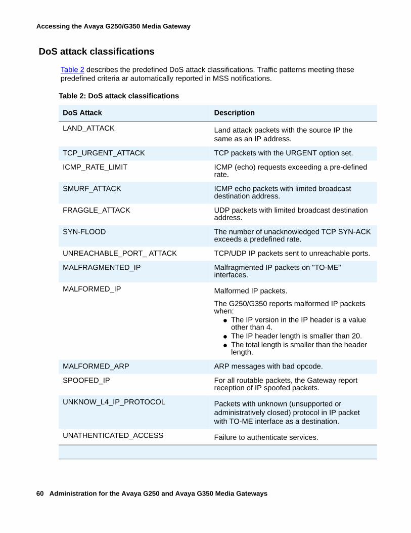
Accessing the Avaya G250/G350 Media Gateway
60 Administration for the Avaya G250 and Avaya G350 Media Gateways
DoS attack classifications
Table 2 describes the predefined DoS attack classifications. Traffic patterns meeting these predefined criteria ar automatically reported in MSS notifications.
Table 2: DoS attack classifications
DoS Attack Description
LAND_ATTACK Land attack packets with the source IP the same as an IP address.
TCP_URGENT_ATTACK TCP packets with the URGENT option set.
ICMP_RATE_LIMIT ICMP (echo) requests exceeding a pre-defined rate.
SMURF_ATTACK ICMP echo packets with limited broadcast destination address.
FRAGGLE_ATTACK UDP packets with limited broadcast destination address.
SYN-FLOOD The number of unacknowledged TCP SYN-ACK exceeds a predefined rate.
UNREACHABLE_PORT_ ATTACK TCP/UDP IP packets sent to unreachable ports.
MALFRAGMENTED_IP Malfragmented IP packets on "TO-ME" interfaces.
MALFORMED_IP Malformed IP packets.
The G250/G350 reports malformed IP packets when:
● The IP version in the IP header is a value other than 4.
● The IP header length is smaller than 20.● The total length is smaller than the header
length.
MALFORMED_ARP ARP messages with bad opcode.
SPOOFED_IP For all routable packets, the Gateway report reception of IP spoofed packets.
UNKNOW_L4_IP_PROTOCOL Packets with unknown (unsupported or administratively closed) protocol in IP packet with TO-ME interface as a destination.
UNATHENTICATED_ACCESS Failure to authenticate services.
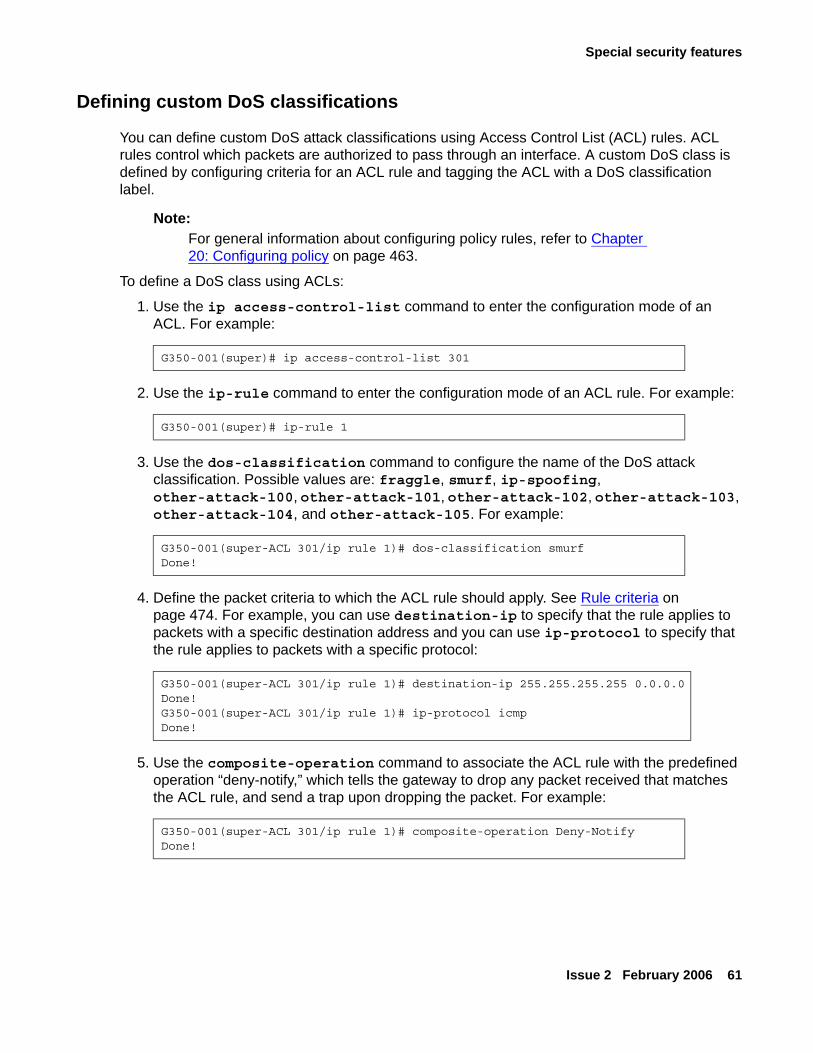
Special security features
Issue 2 February 2006 61
Defining custom DoS classifications
You can define custom DoS attack classifications using Access Control List (ACL) rules. ACL rules control which packets are authorized to pass through an interface. A custom DoS class is defined by configuring criteria for an ACL rule and tagging the ACL with a DoS classification label.
Note:Note: For general information about configuring policy rules, refer to Chapter
20: Configuring policy on page 463.
To define a DoS class using ACLs:
1. Use the ip access-control-list command to enter the configuration mode of an ACL. For example:
2. Use the ip-rule command to enter the configuration mode of an ACL rule. For example:
3. Use the dos-classification command to configure the name of the DoS attack classification. Possible values are: fraggle, smurf, ip-spoofing, other-attack-100, other-attack-101, other-attack-102, other-attack-103, other-attack-104, and other-attack-105. For example:
4. Define the packet criteria to which the ACL rule should apply. See Rule criteria on page 474. For example, you can use destination-ip to specify that the rule applies to packets with a specific destination address and you can use ip-protocol to specify that the rule applies to packets with a specific protocol:
5. Use the composite-operation command to associate the ACL rule with the predefined operation “deny-notify,” which tells the gateway to drop any packet received that matches the ACL rule, and send a trap upon dropping the packet. For example:
G350-001(super)# ip access-control-list 301
G350-001(super)# ip-rule 1
G350-001(super-ACL 301/ip rule 1)# dos-classification smurfDone!
G350-001(super-ACL 301/ip rule 1)# destination-ip 255.255.255.255 0.0.0.0Done!G350-001(super-ACL 301/ip rule 1)# ip-protocol icmpDone!
G350-001(super-ACL 301/ip rule 1)# composite-operation Deny-NotifyDone!
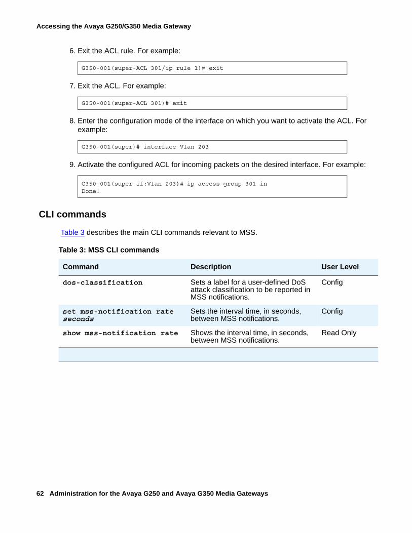
Accessing the Avaya G250/G350 Media Gateway
62 Administration for the Avaya G250 and Avaya G350 Media Gateways
6. Exit the ACL rule. For example:
7. Exit the ACL. For example:
8. Enter the configuration mode of the interface on which you want to activate the ACL. For example:
9. Activate the configured ACL for incoming packets on the desired interface. For example:
CLI commands
Table 3 describes the main CLI commands relevant to MSS.
G350-001(super-ACL 301/ip rule 1)# exit
G350-001(super-ACL 301)# exit
G350-001(super)# interface Vlan 203
G350-001(super-if:Vlan 203)# ip access-group 301 inDone!
Table 3: MSS CLI commands
Command Description User Level
dos-classification Sets a label for a user-defined DoS attack classification to be reported in MSS notifications.
Config
set mss-notification rate seconds
Sets the interval time, in seconds, between MSS notifications.
Config
show mss-notification rate Shows the interval time, in seconds, between MSS notifications.
Read Only
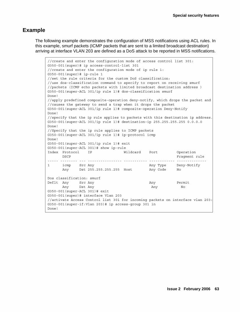
Special security features
Issue 2 February 2006 63
Example
The following example demonstrates the configuration of MSS notifications using ACL rules. In this example, smurf packets (ICMP packets that are sent to a limited broadcast destination) arriving at interface VLAN 203 are defined as a DoS attack to be reported in MSS notifications.
//create and enter the configuration mode of access control list 301:G350-001(super)# ip access-control-list 301//create and enter the configuration mode of ip rule 1:G350-001(super)# ip-rule 1//set the rule criteria for the custom DoS classification://use dos-classification command to specify to report on receiving smurf //packets (ICMP echo packets with limited broadcast destination address )G350-001(super-ACL 301/ip rule 1)# dos-classification smurfDone!//apply predefined composite-operation deny-notify, which drops the packet and //causes the gateway to send a trap when it drops the packetG350-001(super-ACL 301/ip rule 1)# composite-operation Deny-NotifyDone!//specify that the ip rule applies to packets with this destination ip address.G350-001(super-ACL 301/ip rule 1)# destination-ip 255.255.255.255 0.0.0.0Done!//Specify that the ip rule applies to ICMP packetsG350-001(super-ACL 301/ip rule 1)# ip-protocol icmpDone!G350-001(super-ACL 301/ip rule 1)# exitG350-001(super-ACL 301)# show ip-rule Index Protocol IP Wildcard Port Operation
DSCP Fragment rule----- -------- --- ---------------- ----------- ------------ --------------1 icmp Src Any Any Type Deny-Notify
Any Dst 255.255.255.255 Host Any Code No
Dos classification: smurf Deflt Any Src Any Any Permit
Any Dst Any Any No G350-001(super-ACL 301)# exit G350-001(super)# interface Vlan 203//activate Access Control list 301 for incoming packets on interface vlan 203:G350-001(super-if:Vlan 203)# ip access-group 301 inDone!

Accessing the Avaya G250/G350 Media Gateway
64 Administration for the Avaya G250 and Avaya G350 Media Gateways
Issue 2 February 2006 65
Chapter 4: Basic device configuration
This chapter provides information about basic configuration of the Avaya G250/G350 Media Gateway and contains the following sections:
● Defining an interface — instructions on how to define a new interface and its IP address
● Configuring the Primary Management Interface (PMI) — instructions on how to configure parameters that identify the G250/G350 to other devices
● Defining the default gateway — instructions on how to define a G250/G350 interface as the G250/G350’s default gateway
● Configuring the Media Gateway Controller (MGC) — instructions on how to configure an MGC to work with the G250/G350
● DNS Resolver — instructions on how to configure DNS Resolver for resolving host names to IP addresses
● Viewing the status of the device — instructions on how to view the status of the G250/G350
● Version management — instructions on how to manage and upgrade software, firmware, configuration, and other files on the G250/G350
Defining an interfaceAll interfaces on the G250 and G350 must be defined by the administrator, after installation of the G250/G350.
To define an interface:
1. Use the interface command to enter the interface context. Some types of interfaces require an identifier as a parameter. Other types of interfaces require the interface’s module and port number as a parameter. For example:
interface vlan 1interface serial 2/1interface fastethernet 10/2.0
For more information on the various types of interfaces, see Router interface concepts on page 335.
2. Use the ip address command, followed by an IP address and subnet mask, to assign an IP address to the interface.
3. Use the load-interval command to set the load calculation interval for the interface.
Basic device configuration
66 Administration for the Avaya G250 and Avaya G350 Media Gateways
For a list and descriptions of other interface configuration commands, see Configuring interfaces on page 334. For interface configuration examples, see WAN configuration example on page 204.
Configuring the Primary Management Interface (PMI)The Primary Management Interface (PMI) address is the IP address of an interface that you can specify on the Avaya G250/G350 Media Gateway. The first IP address you configure on the G250/G350 automatically becomes the PMI. You can subsequently assign any IP interface to be the PMI.
The PMI is used as the IP address of the G250/G350 for the following management functions:
● Registration of the G250/G350 to an MGC
● Sending SNMP traps
● Opening telnet sessions from the G250/G350
● Sending messages from the G250/G350 using FTP and TFTP protocol
You can designate any of the G250/G350’s interfaces to serve as the G250/G350’s PMI. The PMI must be an IP address that the MGC recognizes. If you are not sure which interface to use as the PMI, check with your system administrator.
To set the PMI of the G250/G350:
1. Use the interface command to enter the context of the interface to which you want to set the PMI. For example, to use the VLAN 1 interface as the PMI, type interface vlan 1.
Note:Note: If the interface has not been defined, you must define it now. See Defining an
interface on page 65.
2. Type the pmi command.
3. Type exit to return to general context.
4. Type the copy running-config startup-config command. This saves the new PMI in the startup configuration file.
5. Use the reset command to reset the G250/G350.
Note:Note: Most configuration changes take effect as soon as you make the change, but
must be saved to the startup configuration file in order to remain in effect after you reset the G250/G350. The PMI address is an exception. A change to the PMI does not take effect at all until you reset the G250/G350.
Defining the default gateway
Issue 2 February 2006 67
6. To verify the new PMI, type the show pmi command in general context. If you use this command before you reset the G250/G350, it displays two different PMIs:
● Active PMI — the PMI the G250/G350 is currently using, as defined in the running configuration file
● Configured PMI — the PMI that the G250/G350 is configured to use after reset, as defined in the startup configuration file
If you use this command after you reset the G250/G350, both the Active and the Configured PMI should be the same IP address.
Use the following commands to configure other identification information:
● Use the set system contact command to set the contact information for the G250/G350.
● Use the set system location command to set the location information for the G250/G350.
● Use the set system name command to specify the name of the G250/G350.
Defining the default gatewayThe G250/G350 uses a default gateway to connect to outside networks that are not listed on the G250/G350’s routing table. To define a default gateway, use the ip default-gateway command, followed by either the IP address or name (type and number) of the interface you want to define as the default gateway.
The following example defines the interface with the IP address 132.55.4.45 as the default gateway:
ip default-gateway 132.55.4.45
The following example defines Serial interface 5/1:1 as the default gateway:
ip default-gateway Serial 5/1:1
Configuring the Media Gateway Controller (MGC)This section provides information about configuring a Media Gateway Controller (MGC) to work with the G250/G350 and includes the following topics:
● The Media Gateway Controller (MGC) — an overview of the types of MGCs that can be used with the G250/G350
● Survivability and migration options — an overview of the features that provide for smooth migration and backup service in the event of a loss of connectivity with the MGC
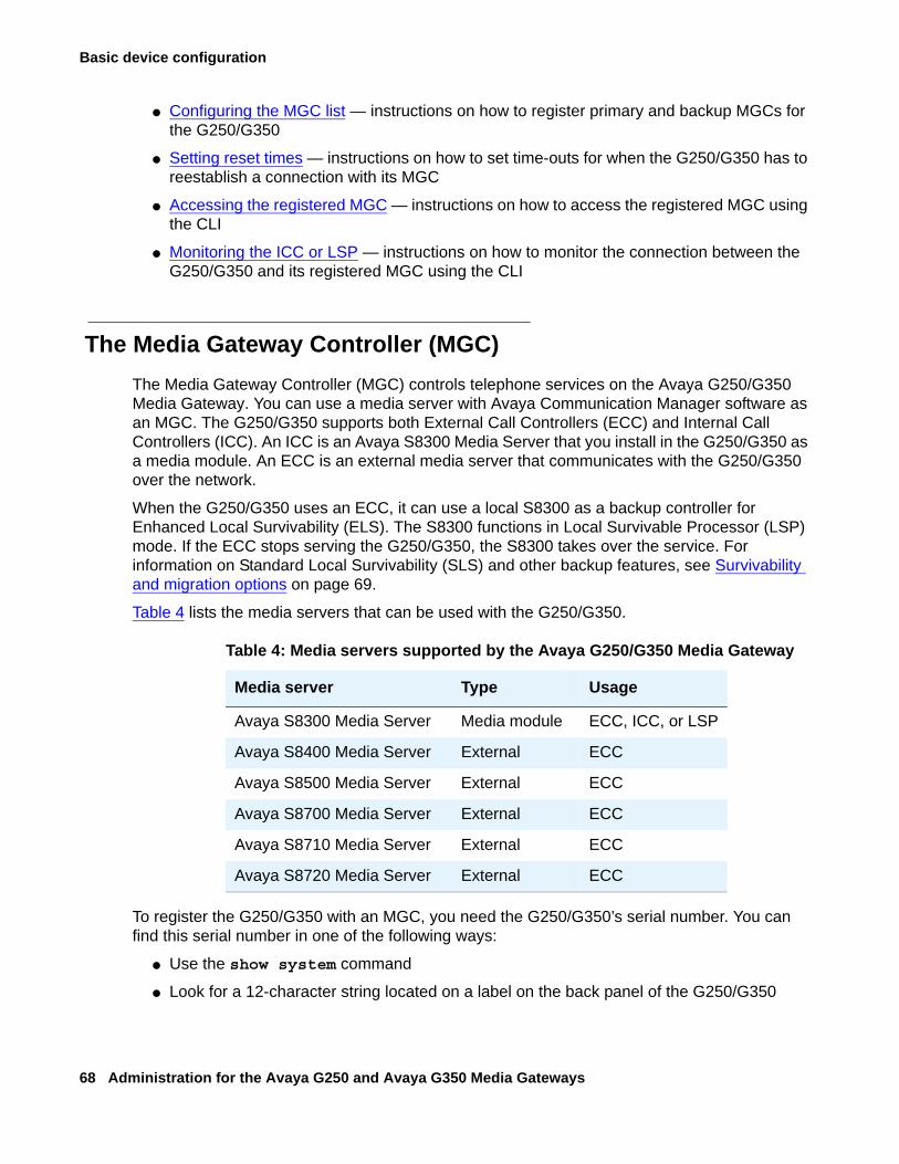
Basic device configuration
68 Administration for the Avaya G250 and Avaya G350 Media Gateways
● Configuring the MGC list — instructions on how to register primary and backup MGCs for the G250/G350
● Setting reset times — instructions on how to set time-outs for when the G250/G350 has to reestablish a connection with its MGC
● Accessing the registered MGC — instructions on how to access the registered MGC using the CLI
● Monitoring the ICC or LSP — instructions on how to monitor the connection between the G250/G350 and its registered MGC using the CLI
The Media Gateway Controller (MGC)The Media Gateway Controller (MGC) controls telephone services on the Avaya G250/G350 Media Gateway. You can use a media server with Avaya Communication Manager software as an MGC. The G250/G350 supports both External Call Controllers (ECC) and Internal Call Controllers (ICC). An ICC is an Avaya S8300 Media Server that you install in the G250/G350 as a media module. An ECC is an external media server that communicates with the G250/G350 over the network.
When the G250/G350 uses an ECC, it can use a local S8300 as a backup controller for Enhanced Local Survivability (ELS). The S8300 functions in Local Survivable Processor (LSP) mode. If the ECC stops serving the G250/G350, the S8300 takes over the service. For information on Standard Local Survivability (SLS) and other backup features, see Survivability and migration options on page 69.
Table 4 lists the media servers that can be used with the G250/G350.
To register the G250/G350 with an MGC, you need the G250/G350’s serial number. You can find this serial number in one of the following ways:
● Use the show system command
● Look for a 12-character string located on a label on the back panel of the G250/G350
Table 4: Media servers supported by the Avaya G250/G350 Media Gateway
Media server Type Usage
Avaya S8300 Media Server Media module ECC, ICC, or LSP
Avaya S8400 Media Server External ECC
Avaya S8500 Media Server External ECC
Avaya S8700 Media Server External ECC
Avaya S8710 Media Server External ECC
Avaya S8720 Media Server External ECC
Configuring the Media Gateway Controller (MGC)
Issue 2 February 2006 69
Survivability and migration optionsSeveral options exist to minimize network disruption in the event that connectivity between the G250/G350 and the MGC is lost.
● MGC list. You must register the G250/G350 with at least one, and up to four, MGCs. The first MGC on the list is the primary MGC. If the G250/G350 cannot connect with, or loses its connection with, the primary MGC, it attempts to connect with the other MGCs on the list. See Configuring the MGC list on page 70.
Note:Note: On a G250 with SLS enabled, the MGC list includes the SLS module as a fifth
entry in the MGC list. For details about SLS, see Chapter 5: Configuring Standard Local Survivability (SLS) on the G250 on page 87.
● Standard Local Survivability (SLS). SLS consists of a module built into the G250 to provide partial backup MGC functionality in the event that the connection with the primary MGC is lost. This feature allows a local G250 to provide a degree of MGC functionality when no link is available to an external MGC. It is configured on a system-wide basis using the Provisioning and Installation Manager (PIM) (see Accessing PIM on page 40). Alternatively, it can be configured on an individual G250 using the CLI. For more information and instructions on configuring SLS, see Chapter 5: Configuring Standard Local Survivability (SLS) on the G250 on page 87.
Note:Note: SLS survivability is not supported on the G350.
● Enhanced Local Survivability (ELS). ELS is available for both the G250 and the G350 using a local S8300 functioning in LSP mode. If the ECC stops serving the G250/G350, the S8300 takes over the service.
● Auto fallback to primary MGC. This feature provides a means by which a G250/G350 being serviced by its LSP can return to its primary MGC automatically when the connection is restored between the G250/G350 and the MSG. By migrating the G250/G350 to the MGC automatically, a fragmented network can be made whole more quickly, without the need for human intervention. Auto fallback is configured via the Avaya Communication Manager. For details, see the Administrator Guide for Avaya Communication Manager, 03-300509.
Note:Note: Auto fallback does not include survivability. Therefore, there is a short period
during registration with the MGC during which calls are dropped and service is not available. This problem can be minimized using the connection preservation feature described below.
● Connection preservation. This feature enables the G250/G350 to preserve the bearer paths of stable calls in the event that the G250/G350 migrates to another MGC (including an LSP), including migration back from an LSP to the primary MGC. A call for which the
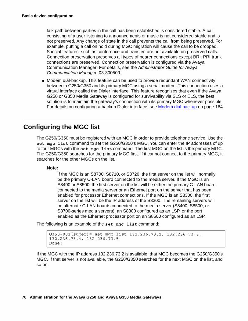
Basic device configuration
70 Administration for the Avaya G250 and Avaya G350 Media Gateways
talk path between parties in the call has been established is considered stable. A call consisting of a user listening to announcements or music is not considered stable and is not preserved. Any change of state in the call prevents the call from being preserved. For example, putting a call on hold during MGC migration will cause the call to be dropped. Special features, such as conference and transfer, are not available on preserved calls. Connection preservation preserves all types of bearer connections except BRI. PRI trunk connections are preserved. Connection preservation is configured via the Avaya Communication Manager. For details, see the Administrator Guide for Avaya Communication Manager, 03-300509.
● Modem dial-backup. This feature can be used to provide redundant WAN connectivity between a G250/G350 and its primary MGC using a serial modem. This connection uses a virtual interface called the Dialer interface. This feature recognizes that even if the Avaya G250 or G350 Media Gateway is configured for survivability via SLS or ELS, the best solution is to maintain the gateway’s connection with its primary MGC whenever possible. For details on configuring a backup Dialer interface, see Modem dial backup on page 164.
Configuring the MGC listThe G250/G350 must be registered with an MGC in order to provide telephone service. Use the set mgc list command to set the G250/G350’s MGC. You can enter the IP addresses of up to four MGCs with the set mgc list command. The first MGC on the list is the primary MGC. The G250/G350 searches for the primary MGC first. If it cannot connect to the primary MGC, it searches for the other MGCs on the list.
Note:Note: If the MGC is an S8700, S8710, or S8720, the first server on the list will normally
be the primary C-LAN board connected to the media server. If the MGC is an S8400 or S8500, the first server on the list will be either the primary C-LAN board connected to the media server or an Ethernet port on the server that has been enabled for processor Ethernet connections. If the MGC is an S8300, the first server on the list will be the IP address of the S8300. The remaining servers will be alternate C-LAN boards connected to the media server (S8400, S8500, or S8700-series media servers), an S8300 configured as an LSP, or the port enabled as the Ethernet processor port on an S8500 configured as an LSP.
The following is an example of the set mgc list command:
If the MGC with the IP address 132.236.73.2 is available, that MGC becomes the G250/G350’s MGC. If that server is not available, the G250/G350 searches for the next MGC on the list, and so on.
G350-001(super)# set mgc list 132.236.73.2, 132.236.73.3, 132.236.73.4, 132.236.73.5Done!
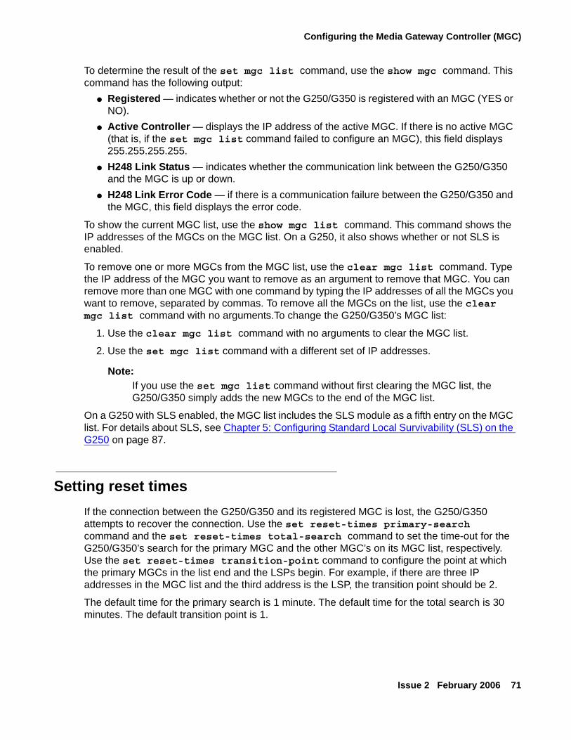
Configuring the Media Gateway Controller (MGC)
Issue 2 February 2006 71
To determine the result of the set mgc list command, use the show mgc command. This command has the following output:
● Registered — indicates whether or not the G250/G350 is registered with an MGC (YES or NO).
● Active Controller — displays the IP address of the active MGC. If there is no active MGC (that is, if the set mgc list command failed to configure an MGC), this field displays 255.255.255.255.
● H248 Link Status — indicates whether the communication link between the G250/G350 and the MGC is up or down.
● H248 Link Error Code — if there is a communication failure between the G250/G350 and the MGC, this field displays the error code.
To show the current MGC list, use the show mgc list command. This command shows the IP addresses of the MGCs on the MGC list. On a G250, it also shows whether or not SLS is enabled.
To remove one or more MGCs from the MGC list, use the clear mgc list command. Type the IP address of the MGC you want to remove as an argument to remove that MGC. You can remove more than one MGC with one command by typing the IP addresses of all the MGCs you want to remove, separated by commas. To remove all the MGCs on the list, use the clear mgc list command with no arguments.To change the G250/G350’s MGC list:
1. Use the clear mgc list command with no arguments to clear the MGC list.
2. Use the set mgc list command with a different set of IP addresses.
Note:Note: If you use the set mgc list command without first clearing the MGC list, the
G250/G350 simply adds the new MGCs to the end of the MGC list.
On a G250 with SLS enabled, the MGC list includes the SLS module as a fifth entry on the MGC list. For details about SLS, see Chapter 5: Configuring Standard Local Survivability (SLS) on the G250 on page 87.
Setting reset timesIf the connection between the G250/G350 and its registered MGC is lost, the G250/G350 attempts to recover the connection. Use the set reset-times primary-search command and the set reset-times total-search command to set the time-out for the G250/G350’s search for the primary MGC and the other MGC’s on its MGC list, respectively. Use the set reset-times transition-point command to configure the point at which the primary MGCs in the list end and the LSPs begin. For example, if there are three IP addresses in the MGC list and the third address is the LSP, the transition point should be 2.
The default time for the primary search is 1 minute. The default time for the total search is 30 minutes. The default transition point is 1.
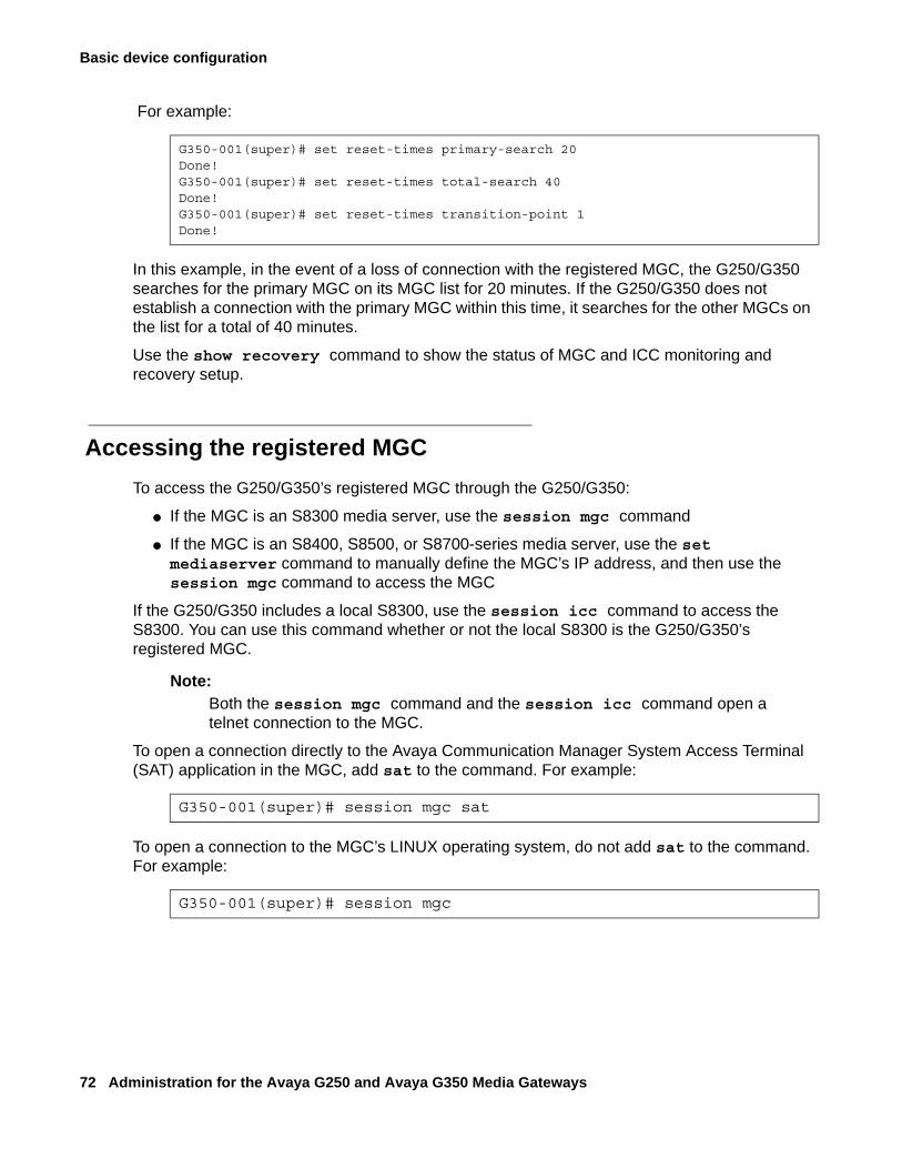
Basic device configuration
72 Administration for the Avaya G250 and Avaya G350 Media Gateways
For example:
In this example, in the event of a loss of connection with the registered MGC, the G250/G350 searches for the primary MGC on its MGC list for 20 minutes. If the G250/G350 does not establish a connection with the primary MGC within this time, it searches for the other MGCs on the list for a total of 40 minutes.
Use the show recovery command to show the status of MGC and ICC monitoring and recovery setup.
Accessing the registered MGCTo access the G250/G350’s registered MGC through the G250/G350:
● If the MGC is an S8300 media server, use the session mgc command
● If the MGC is an S8400, S8500, or S8700-series media server, use the set mediaserver command to manually define the MGC’s IP address, and then use the session mgc command to access the MGC
If the G250/G350 includes a local S8300, use the session icc command to access the S8300. You can use this command whether or not the local S8300 is the G250/G350’s registered MGC.
Note:Note: Both the session mgc command and the session icc command open a
telnet connection to the MGC.
To open a connection directly to the Avaya Communication Manager System Access Terminal (SAT) application in the MGC, add sat to the command. For example:
To open a connection to the MGC’s LINUX operating system, do not add sat to the command. For example:
G350-001(super)# set reset-times primary-search 20Done!G350-001(super)# set reset-times total-search 40Done!G350-001(super)# set reset-times transition-point 1Done!
G350-001(super)# session mgc sat
G350-001(super)# session mgc
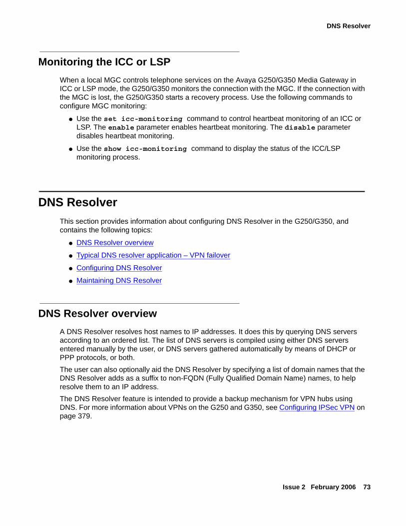
DNS Resolver
Issue 2 February 2006 73
Monitoring the ICC or LSPWhen a local MGC controls telephone services on the Avaya G250/G350 Media Gateway in ICC or LSP mode, the G250/G350 monitors the connection with the MGC. If the connection with the MGC is lost, the G250/G350 starts a recovery process. Use the following commands to configure MGC monitoring:
● Use the set icc-monitoring command to control heartbeat monitoring of an ICC or LSP. The enable parameter enables heartbeat monitoring. The disable parameter disables heartbeat monitoring.
● Use the show icc-monitoring command to display the status of the ICC/LSP monitoring process.
DNS ResolverThis section provides information about configuring DNS Resolver in the G250/G350, and contains the following topics:
● DNS Resolver overview
● Typical DNS resolver application – VPN failover
● Configuring DNS Resolver
● Maintaining DNS Resolver
DNS Resolver overviewA DNS Resolver resolves host names to IP addresses. It does this by querying DNS servers according to an ordered list. The list of DNS servers is compiled using either DNS servers entered manually by the user, or DNS servers gathered automatically by means of DHCP or PPP protocols, or both.The user can also optionally aid the DNS Resolver by specifying a list of domain names that the DNS Resolver adds as a suffix to non-FQDN (Fully Qualified Domain Name) names, to help resolve them to an IP address.The DNS Resolver feature is intended to provide a backup mechanism for VPN hubs using DNS. For more information about VPNs on the G250 and G350, see Configuring IPSec VPN on page 379.
Basic device configuration
74 Administration for the Avaya G250 and Avaya G350 Media Gateways
DNS Resolver FeaturesThe G250/G350 supports the following DNS Resolver features:
● Fully compliant with RFC1034, RFC1035 and RFC1123.
● Maintains a global DNS database for all interfaces. The database is compiled using:
● Static (user-defined) DNS servers.
● Automatically-learned DNS servers. DNS servers can be automatically learned by the Fast Ethernet 10/2 interface when it is configured as a DHCP client or configured for PPP. For more information on DHCP Client, see Configuring DHCP client on page 112.
Note:Note: The following PPP interfaces can be configured to automatically learn the DNS
servers in the system:
- Fast Ethernet with PPPoE- Dialer interface- Serial interface
The most common application of this configuration is for connecting the G250/G350 to the Internet and getting the DNS server information from the ISP. Therefore, interfaces configured to automatically learn the DNS servers in the system are usually the Fast Ethernet with PPPoE interface and the Dialer interface.
Typical DNS resolver application – VPN failoverIn this typical application, the DNS Resolver feature is used to provide a VPN failover mechanism between two main offices. The failover mechanism is implemented as follows.The VPN branch office(s) connect to two main offices (the VPN remote peers) that are configured with the same FQDN name, but have different IP addresses. When a branch office makes a DNS query to resolve the VPN remote peer name to an IP address, it receives a list with the IP addresses of both main offices, selects the first one, and builds a VPN tunnel with it. If the first main office fails, the branch office sends another DNS query, and receives in reply the IP address of the second main office. It will then start a VPN tunnel with the second main office.This typical application is described in full in Failover using DNS on page 444.
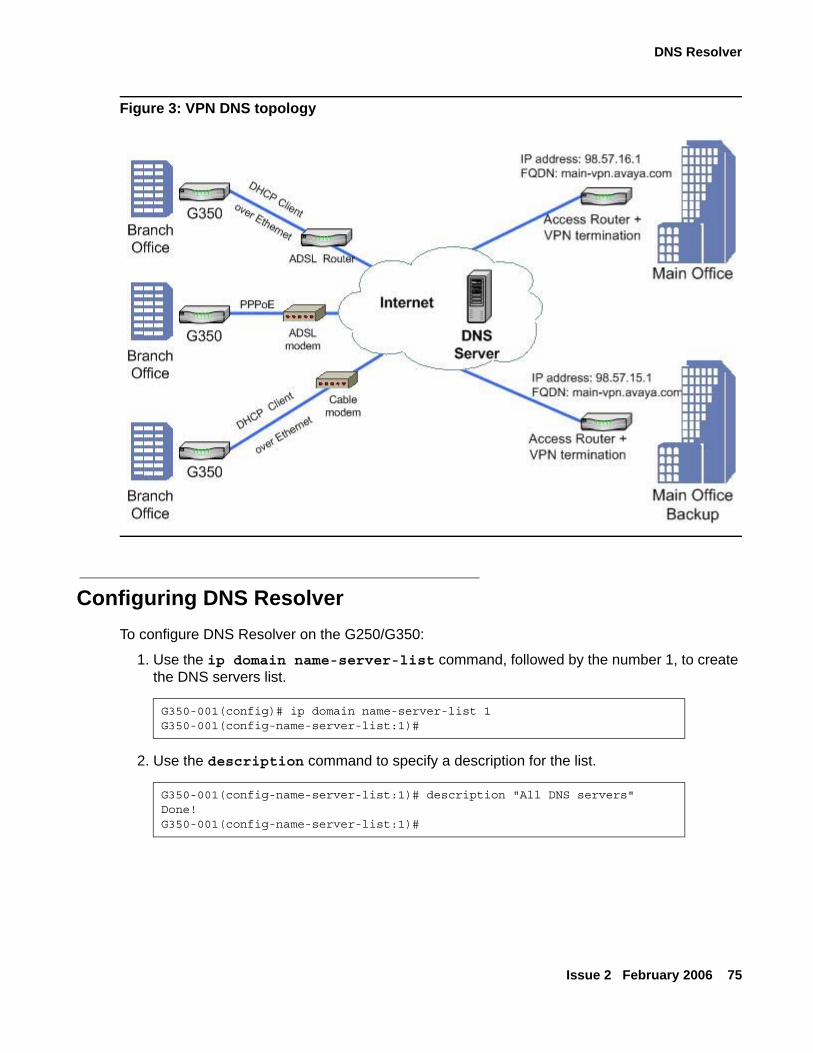
DNS Resolver
Issue 2 February 2006 75
Figure 3: VPN DNS topology
Configuring DNS ResolverTo configure DNS Resolver on the G250/G350:
1. Use the ip domain name-server-list command, followed by the number 1, to create the DNS servers list.
2. Use the description command to specify a description for the list.
G350-001(config)# ip domain name-server-list 1G350-001(config-name-server-list:1)#
G350-001(config-name-server-list:1)# description "All DNS servers"Done!G350-001(config-name-server-list:1)#
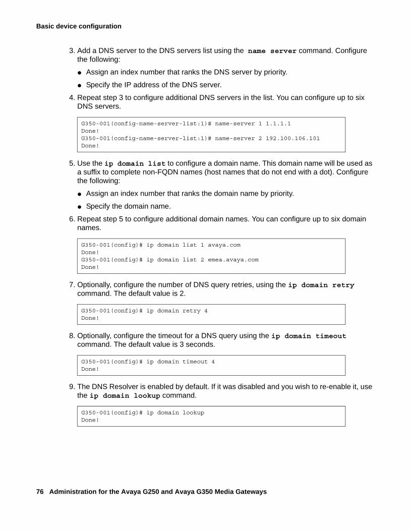
Basic device configuration
76 Administration for the Avaya G250 and Avaya G350 Media Gateways
3. Add a DNS server to the DNS servers list using the name server command. Configure the following:
● Assign an index number that ranks the DNS server by priority.
● Specify the IP address of the DNS server.
4. Repeat step 3 to configure additional DNS servers in the list. You can configure up to six DNS servers.
5. Use the ip domain list to configure a domain name. This domain name will be used as a suffix to complete non-FQDN names (host names that do not end with a dot). Configure the following:
● Assign an index number that ranks the domain name by priority.
● Specify the domain name.
6. Repeat step 5 to configure additional domain names. You can configure up to six domain names.
7. Optionally, configure the number of DNS query retries, using the ip domain retry command. The default value is 2.
8. Optionally, configure the timeout for a DNS query using the ip domain timeout command. The default value is 3 seconds.
9. The DNS Resolver is enabled by default. If it was disabled and you wish to re-enable it, use the ip domain lookup command.
G350-001(config-name-server-list:1)# name-server 1 1.1.1.1Done!G350-001(config-name-server-list:1)# name-server 2 192.100.106.101Done!
G350-001(config)# ip domain list 1 avaya.comDone!G350-001(config)# ip domain list 2 emea.avaya.comDone!
G350-001(config)# ip domain retry 4Done!
G350-001(config)# ip domain timeout 4Done!
G350-001(config)# ip domain lookupDone!
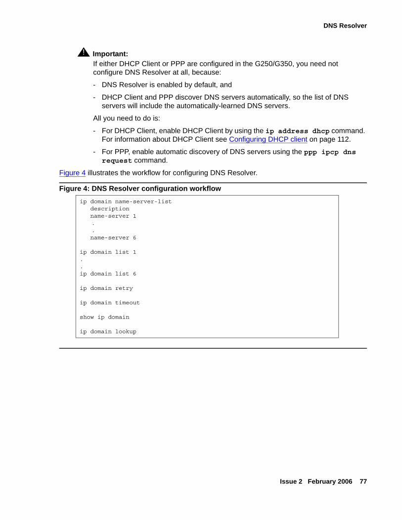
DNS Resolver
Issue 2 February 2006 77
! Important:Important: If either DHCP Client or PPP are configured in the G250/G350, you need not
configure DNS Resolver at all, because:
- DNS Resolver is enabled by default, and
- DHCP Client and PPP discover DNS servers automatically, so the list of DNS servers will include the automatically-learned DNS servers.
All you need to do is:
- For DHCP Client, enable DHCP Client by using the ip address dhcp command. For information about DHCP Client see Configuring DHCP client on page 112.
- For PPP, enable automatic discovery of DNS servers using the ppp ipcp dns request command.
Figure 4 illustrates the workflow for configuring DNS Resolver.
Figure 4: DNS Resolver configuration workflowip domain name-server-list description name-server 1
.
. name-server 6
ip domain list 1..ip domain list 6
ip domain retry
ip domain timeout
show ip domain
ip domain lookup
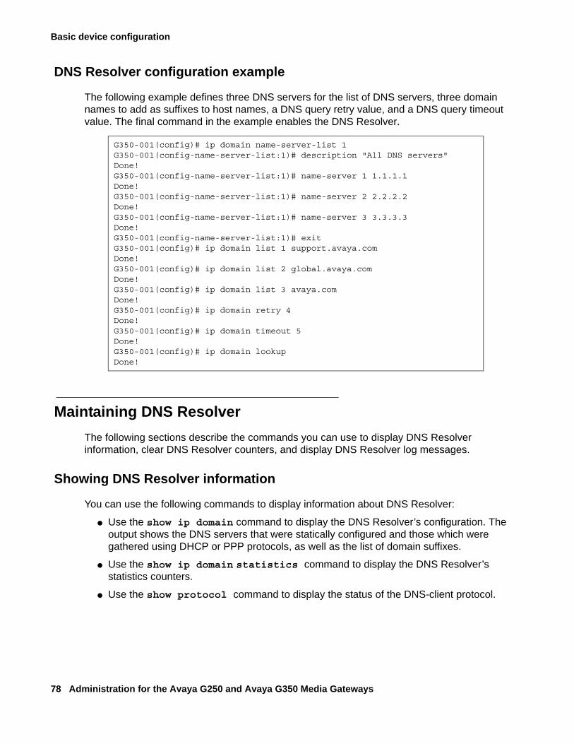
Basic device configuration
78 Administration for the Avaya G250 and Avaya G350 Media Gateways
DNS Resolver configuration example
The following example defines three DNS servers for the list of DNS servers, three domain names to add as suffixes to host names, a DNS query retry value, and a DNS query timeout value. The final command in the example enables the DNS Resolver.
Maintaining DNS ResolverThe following sections describe the commands you can use to display DNS Resolver information, clear DNS Resolver counters, and display DNS Resolver log messages.
Showing DNS Resolver information
You can use the following commands to display information about DNS Resolver:
● Use the show ip domain command to display the DNS Resolver’s configuration. The output shows the DNS servers that were statically configured and those which were gathered using DHCP or PPP protocols, as well as the list of domain suffixes.
● Use the show ip domain statistics command to display the DNS Resolver’s statistics counters.
● Use the show protocol command to display the status of the DNS-client protocol.
G350-001(config)# ip domain name-server-list 1G350-001(config-name-server-list:1)# description "All DNS servers"Done!G350-001(config-name-server-list:1)# name-server 1 1.1.1.1Done!G350-001(config-name-server-list:1)# name-server 2 2.2.2.2Done!G350-001(config-name-server-list:1)# name-server 3 3.3.3.3Done!G350-001(config-name-server-list:1)# exitG350-001(config)# ip domain list 1 support.avaya.comDone!G350-001(config)# ip domain list 2 global.avaya.comDone!G350-001(config)# ip domain list 3 avaya.comDone!G350-001(config)# ip domain retry 4Done!G350-001(config)# ip domain timeout 5Done!G350-001(config)# ip domain lookupDone!
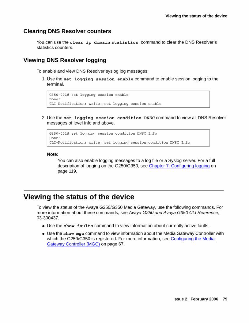
Viewing the status of the device
Issue 2 February 2006 79
Clearing DNS Resolver counters
You can use the clear ip domain statistics command to clear the DNS Resolver’s statistics counters.
Viewing DNS Resolver logging
To enable and view DNS Resolver syslog log messages:
1. Use the set logging session enable command to enable session logging to the terminal.
2. Use the set logging session condition DNSC command to view all DNS Resolver messages of level Info and above.
Note:Note: You can also enable logging messages to a log file or a Syslog server. For a full
description of logging on the G250/G350, see Chapter 7: Configuring logging on page 119.
Viewing the status of the deviceTo view the status of the Avaya G250/G350 Media Gateway, use the following commands. For more information about these commands, see Avaya G250 and Avaya G350 CLI Reference, 03-300437.
● Use the show faults command to view information about currently active faults.
● Use the show mgc command to view information about the Media Gateway Controller with which the G250/G350 is registered. For more information, see Configuring the Media Gateway Controller (MGC) on page 67.
G350-001# set logging session enableDone!CLI-Notification: write: set logging session enable
G350-001# set logging session condition DNSC InfoDone!CLI-Notification: write: set logging session condition DNSC Info
Basic device configuration
80 Administration for the Avaya G250 and Avaya G350 Media Gateways
● Use the show mm command to view information about media modules that are installed on the G250/G350. To view information about a specific media module, include the slot number of the media module as an argument. For example, to view information about the media module in slot 2, enter show mm v2. The output of the command shows the following information:
- Slot number- Uptime- Type of media module- Description- Serial number and other hardware identification numbers- Firmware version- Number of ports- Fault messages
● Use the show module command or the show mg list command to view brief information about media modules that are installed in the G250/G350. To view brief information about a specific media module, include the slot number of the media module as an argument. For example, to view information about the media module in slot 2, enter show module v2. The output of the command shows the following information:
- Slot number
- Firmware version
- Type of media module
- Media module code
● Use the show system command to display the serial number of the G250/G350, the G250/G350’s uptime, the firmware version number, MAC addresses, and other system information.
● Use the show restart-log command to view information about the last time that the G250/G350 was reset.
● Use the show temp command to view the temperature of the G250/G350 CPU. This command also displays the high and low temperatures that will trigger a temperature warning.
● Use the show voltages command to view the power supply voltages of the G250/G350.
● Use the show utilization command to display information about CPU and memory usage on the G250/G350.
Note:Note: Before using this command, you must first use the set utilization cpu
command to enable CPU utilization measurements.
Version management
Issue 2 February 2006 81
● Use the test led command to test the system ALM and MDM and system CPU LEDs on the front panel of the G250/G350. The CPU and media module LEDs blink for five seconds.
Version managementThis section provides information about managing and upgrading software, firmware, configuration, and other files on the Avaya G250/G350 Media Gateway and contains the following sections:
● File transfer — overview of transferring software and firmware files to the G250/G350
● Software and firmware upgrades — instructions on how to upgrade software and firmware
● Managing configuration files — instructions on how to manage configuration files
● Listing the files on the Avaya G250/G350 Media Gateway — instructions on how to display a list of G250/G350 files and their version numbers
File transferThe Avaya G250/G350 Media Gateway can be a client for the FTP and TFTP protocols. Use the FTP or TFTP protocols to transfer files between the Avaya G250/G350 Media Gateway and other devices. You can use file transfer to:
● Install software and firmware upgrades on the G250/G350
● Install firmware upgrades on media modules
● Back up and restore configuration settings
To use file transfer, you need to have an FTP server or TFTP server on your network.
Note:Note: If you use an FTP server, the G250/G350 prompts you for a username and
password when you enter a command to transfer a file. Also, when opening an FTP connection to the S8300, all anonymous FTP file transfers are restricted to the /pub directory. Permission for anonymous FTP users to create files in other directories is denied.
Basic device configuration
82 Administration for the Avaya G250 and Avaya G350 Media Gateways
Software and firmware upgradesYou can upgrade software on the Avaya G250/G350 Media Gateway. Software used to control the Avaya G250/G350 Media Gateway itself and media modules installed on the G250/G350 is called firmware. Use the FTP or TFTP protocol to upload a new version of software or firmware. You can upgrade the following types of software and firmware:
● Firmware for the Avaya G250/G350 Media Gateway
● Java applet for Avaya G350 Manager (G350 only)
● Firmware for media modules
Note:Note: You can also use the G250/G350 to upgrade the firmware and configuration files
for IP phones. For details, see Installing and Upgrading the Avaya G250 Media Gateway, 03-300434 or Installing and Upgrading the Avaya G350 Media Gateway, 03-300394.
Managing the firmware banks
The G250/G350 has two firmware banks:
● Bank A
● Bank B
Each firmware bank contains a version of the G250/G350 firmware. These may be different versions. The purpose of this feature is to provide software redundancy. If one of the versions becomes corrupted, you can reset the G250/G350 using the other version. This is particularly important when uploading new versions.
By default, when you turn on or reset the G250/G350, the G250/G350 loads firmware from Bank B. To change the default bank from which firmware is loaded during startup, type the set boot bank command. For example, to configure the G250/G350 to load firmware from Bank A on startup, type set boot bank bank-A. After typing the set boot bank command, you must type the copy running-config startup-config command to save the change. Now, when you reset the G250/G350, it will load firmware from Bank A.
You can use the ASB button on the G250/G350 front panel to load firmware from the bank other than the default bank during startup:
1. Press and hold the reset button.
2. Press and hold the ASB button.
3. Release the reset button.
4. Release the ASB button.
For example, if the G250/G350 is configured to load firmware from Bank B, use the steps listed above to reset the G250/G350 to load the firmware from Bank A instead.
Version management
Issue 2 February 2006 83
To display the bank from which the G250/G350 is currently set to load its firmware upon startup or reset, type the show boot bank command.
Upgrading software and firmware
To upgrade software or firmware, you must obtain an upgrade file from Avaya. Place the file on your FTP or TFTP server. Then, use one of the following commands to upload the file to the G250/G350. For each of these commands, include the full path of the file and the IP address of the FTP or TFTP host as parameters. When you enter the command, the CLI prompts you for a username and password.
Note:Note: In addition to using the CLI to upgrade software and firmware, you can use the
Avaya IW and the GIW. See Accessing Avaya IW on page 36 and Accessing GIW on page 38.
● Use the copy ftp EW_archive command to upgrade the Java applet for Avaya G350 Manager software from an FTP server.
Note:Note: This command is not supported on the G250.
● Use the copy ftp module command, followed by the module number of the module you want to upgrade, to upgrade the firmware on a media module from an FTP server.
● Use the copy ftp SW_imageA command to upgrade the G250/G350 firmware into Bank A from an FTP server.
● Use the copy ftp SW_imageB command to upgrade the G250/G350 firmware into Bank B from an FTP server.
● Use the copy tftp EW_archive command to upgrade the Java applet for Avaya G350 Manager software from a TFTP server.
Note:Note: This command is not supported on the G250.
● Use the copy tftp module command, followed by the module number of the module you want to upgrade, to upgrade the firmware on a media module from a TFTP server.
● Use the copy tftp SW_imageA command to upgrade the G250/G350 firmware into Bank A from a TFTP server.
● Use the copy tftp SW_imageB command to upgrade the G250/G350 firmware into Bank B from a TFTP server.
● Use the copy ftp EW_archive command to upgrade the Java applet for Avaya G350 Manager software from an FTP server.
Note:Note: This command is not supported on the G250.
Basic device configuration
84 Administration for the Avaya G250 and Avaya G350 Media Gateways
● Use the copy ftp module command, followed by the module number of the module you want to upgrade, to upgrade the firmware on a media module from an FTP server.
● Use the copy ftp SW_imageA command to upgrade the G250/G350 firmware into Bank A from an FTP server.
● Use the copy ftp SW_imageB command to upgrade the G250/G350 firmware into Bank B from an FTP server.
● Use the copy tftp EW_archive command to upgrade the Java applet for Avaya G350 Manager software from a TFTP server.
Note:Note: This command is not supported on the G250.
● Use the copy tftp module command, followed by the module number of the module you want to upgrade, to upgrade the firmware on a media module from a TFTP server.
● Use the copy tftp SW_imageA command to upgrade the G250/G350 firmware into Bank A from a TFTP server.
● Use the copy tftp SW_imageB command to upgrade the G250/G350 firmware into Bank B from a TFTP server.
When using FTP or TFTP commands, you must use the specific path to the file on the FTP or TFTP server according to the home directory of the service (FTP or TFTP) that you are using. For example, to upgrade the firmware of an MM710 media module in slot 2 from a TFTP server with the IP address 192.1.1.10, where the home directory is c:\home\ftp\ and the upgrade file is located in the directory c:\home\ftp\version, use the following command:
copy tftp module \version\mm710v3.fdl 192.1.1.10 2
Note:Note: When uploading firmware from the S8300, use only the file name, without the
directory path, in the command line. Otherwise, the procedure will fail. For instance, in the example above, you must use the following command:copy tftp module mm710v3.fdl 192.1.1.10 2
Note:Note: When uploading firmware from the S8300 using TFTP, you may need to enable
TFTP service in the Set LAN Security parameters of your web server.
The following example uploads a firmware version with the path and file name C:\g350.net from an FTP server with the IP address 149.49.134.153 to Bank A of the G350:
copy ftp SW_imageA C:\g350.net 149.49.134.153
Version management
Issue 2 February 2006 85
Managing configuration filesA configuration file is a data file that contains a complete set of configuration settings for the Avaya G250/G350 Media Gateway. You can use configuration files to back up and restore the configuration of the G250/G350. Use the FTP or TFTP protocol to transfer a configuration file between the G250/G350 and a server on the network. You can back up either the running configuration or the startup configuration to the server as a configuration file. When you restore a configuration file from a server, it becomes the startup configuration on the G250/G350. For more information about running configuration and startup configuration, see Configuration using GUI applications on page 27.
To transfer a configuration file between the G250/G350 and a server on the network, use one of the following commands:
● Use the copy ftp startup-config command to restore a configuration file from an FTP server. The configuration file becomes the startup configuration on the G250/G350.
● Use the copy tftp startup-config command to restore a configuration file from a TFTP server. The configuration file becomes the startup configuration on the G250/G350.
● Use the copy running-config ftp command to back up the running configuration on the G250/G350 to an FTP server.
● Use the copy running-config tftp command to back up the running configuration on the G250/G350 to a TFTP server.
● Use the copy startup-config ftp command to back up the startup configuration on the G250/G350 to an FTP server.
● Use the copy startup-config tftp command to back up the startup configuration on the G250/G350 to a TFTP server.
Listing the files on the Avaya G250/G350 Media GatewayUse the dir command to list all G250/G350 files. When you list the files, you can see the version numbers of the software components. The dir command also shows the booter file, which cannot be changed.

Basic device configuration
86 Administration for the Avaya G250 and Avaya G350 Media Gateways
Issue 2 February 2006 87
Chapter 5: Configuring Standard Local Survivability(SLS) on the G250
Standard Local Survivability (SLS) provides a local G250 with a limited subset of MGC functionality when there is no IP-routed WAN link available to an MGC or no MGC is available.
This chapter provides information about configuring SLS on the G250 and includes the following sections:
● SLS overview
● Configuring SLS
SLS overviewSLS provides:
● Call capability for analog, DCP, and IP phones
● Outbound dialing through the local PSTN (local trunk gateway) from analog, DCP, and IP phones
● Inbound calls from each trunk to pre-configured local analog or IP phones that have registered
● Direct Inward Dialing
● Multiple call appearances
● Hold and Call Transfer functions
● Contact closure feature
● Local call progress tones (dial tone, busy, etc.)
● Emergency Transfer Relay (ETR) in cases of power loss
● Auto Fallback to primary MGC
● IP station registration
SLS is not a replacement for ELS or LSP survivability, which offer full call-feature functionality and full translations in the survivable mode. Instead, SLS is a cost-effective survivability alternative offering limited call processing in survivable mode. Although the G250 has an option to host an S8300 Media Server in ICC or LSP mode, SLS offers both local survivability and call control.
Configuring Standard Local Survivability (SLS) on the G250
88 Administration for the Avaya G250 and Avaya G350 Media Gateways
In contrast to the server-based survivability features, SLS operates entirely from the media gateway and requires a data set comprised of Avaya Communication Manager translations (Survivable ARS Analysis and configuration data). This data set is compiled and distributed to a group of devices using the Provisioning and Installation Manager (PIM). In the absence of PIM, the data set can be configured manually from individual media gateways using CLI commands. For instructions on configuring SLS, see Configuring SLS on page 94.
Call processing in SLS modeIn survivable mode, SLS provides only a limited subset of Avaya Communication Manager call processing functionality:
● Limited call routing through a Survivable ARS Analysis Table (in the PIM application or through the CLI) and COR calling permissions.
● Inbound calls are directed to a previously-administered pool of available stations (the Survivable Trunk Dest? field is y on the Station form). The search algorithm is circular so that the incoming calls are fairly distributed.
! Important:Important: SLS permits 911 calls, but the specific location information is not transmitted to
the Public Service Answering Point (PSAP) but only the general trunk-identifying information. Emergency personnel will have a general location associated with the trunk (for example, a building address), but nothing more specific like the room or office number. Also, If a 911 call disconnects for any reason, emergency personnel cannot reliably call the originator back.
● Communication Manager Feature Access Codes for ARS, Contact Closure, and Hold● Acts as H.323 Gatekeeper that allows IP endpoints to register simultaneously● Direct Inward Dialing● Multiple call appearances● Hold and Call Transfer functions● Contact closure feature● Call Detail Recording (CDR, see SLS logging activities on page 92)● Trunk Access Code (TAC) dialing● Centrex features
Note:Note: SLS cannot add or delete digits for outbound calls to the analog loop-start (CO)
trunk. This means that Centrex users, for example, must manually dial the extra digit(s) before they can call out to the PSTN. If the CO access code is “9,” then a Centrex customer would have to dial “9-555-1212” for local directory service. If this Centrex access code is not dialed correctly, the local outbound PSTN call will not complete successfully.
SLS overview
Issue 2 February 2006 89
SLS does not support the following functionality in Release 3.1:
● Many small business customers employ custom calling features like call waiting from the BOC/LEC, attempting a more PBX-like capability. These features are not supported by SLS.
● ISDN BRI trunks
● E1/T1-PRI trunks
● T1 In-band signaling on trunks
● E1 In-band signaling on trunks
● ‘Calling party name/number’ information to digital station displays
● Caller ID on outgoing analog station calls
● Caller ID on incoming analog loop-start trunk calls
● 3-party conferences
● Last Number Redial
● Call Forwarding-Busy/Don’t Answer
● No Music On Hold source or announcement playback
● Call Center features, including ASAI
● Connection Preserving Failover/Failback for H.248 Gateways
Provisioning dataSLS requires that the G250 Media Gateway has connected to an MGC at least once and has received provisioning information, including:
● Avaya Communication Manager port information through the H.248 control channel
- Tone sources, including a distinctly different dial tone to inform users that the system is operating in survivable mode
- Loss plan
● Avaya Communication Manager analog resource information through the CCMS channel
● Provisioning and Installation Manager (PIM) queries Avaya Communication Manager for station/trunk configuration and dialplan routing administration data through SNMP
For information on administering SLS in the Avaya Communication Manager, see “Network Recovery” in Maintenance Procedures for Avaya Communication Manager 3.1, Media Gateways and Servers, 03-300432.
Configuring Standard Local Survivability (SLS) on the G250
90 Administration for the Avaya G250 and Avaya G350 Media Gateways
SLS also requires PIM configuration data, some of which the G250 extracts from the Avaya Communication Manager translations. PIM aggregates the required data and copies the provisioning data over a secure communication path to non-volatile RAM (NVRAM) on the G250. After the initial data collection, PIM retains a copy of the data set for each G250. This set is compared with subsequent data sets to determine if anything has changed:
● If the data set changes, then the newer data set is pushed down to the media gateway.
● If the data set does not change, then the data set in NVRAM remains unchanged.
Users can schedule when to collect and push data, perform scheduled and manual backups, and enable and disable SLS, as well as display (but not change) the data to ensure correct information.If PIM is unavailable, the SLS data set can be manually configured in the G250 CLI. For information on configuring SLS, both manually and via PIM, see Configuring SLS on page 94.
Entering SLS modeWhen SLS is enabled, the MGC list displays a fifth element called survivable-call-engine. This element is always past the Transition Point. After the Link Recovery search concludes for the primary MGC list (entries above the Transition Point), it then searches the alternate MGC list (entries below the Transition Point), ending with survivable-call-engine, the last choice for the G250.When the Link Recovery search settles on the survivable-call-engine entry in the MGC list, then the G250 registers with SLS (resident on the G250) for its call control. This section discusses each of the four possible SLS states and the transitions from one state to another.
Unregistered
This is the normal state in which SLS waits for an H.248 registration request from the G250. When SLS receives the request, it registers the G250 and transitions to the Setup state.
Setup
In this transitional state, SLS performs the following activities:
1. Checks for proper provisioning data. If there is insufficient provisioning, then the registration request is denied, and SLS returns to the Unregistered state.
2. Initializes SLS components such as gatekeeper data (for example, IP endpoint’s E.164 addresses and passwords), dial plan, and ARS routing.
3. Completes H.248 registration with SLS.
4. Creates the H.323 GateKeeper socket after successful registration.
When Setup is complete, SLS transitions to the Registered state.
SLS overview
Issue 2 February 2006 91
Registered
SLS can only process calls while it is in the Registered state in which it:
1. Constructs endpoint objects based on board insertion and IP registration
2. Tears down endpoint objects based on board removal and IP unregistration
3. Handles registration requests from H.323 endpoints that display the IP address that has been discovered (the G250 IP address) or searching for.
4. Handles stimuli from all interfaces
SLS remains in the Registered state as long as the socket to SLS is open.
Teardown
SLS transitions to the Teardown state whenever:
● The G250 administrator uses the set survivable-call-engine disable command from the G250 CLI.
-or-
● The G250 closes the SLS socket after maintenance determines that it has completed an H.248 registration with the primary MGC.
● SLS determines that it needs to unregister with the G250 due to internal error conditions.
In this transitional state SLS:
1. Tears down endpoint objects
2. Sends unregistrations requests to IP endpoints that are not on active calls. IP endpoints lose registration with SLS and display the discovered IP address during re-registration with an MGC.
3. Closes the H.323 GateKeeper socket
After Teardown has completed, SLS transitions to the Unregistered state.
SLS interaction with specific G250/G350 featuresFor a description of how SLS interacts with specific G250/G350 features, refer to Maintenance for the Avaya G250 and Avaya G350 Media Gateways, 03-300438.
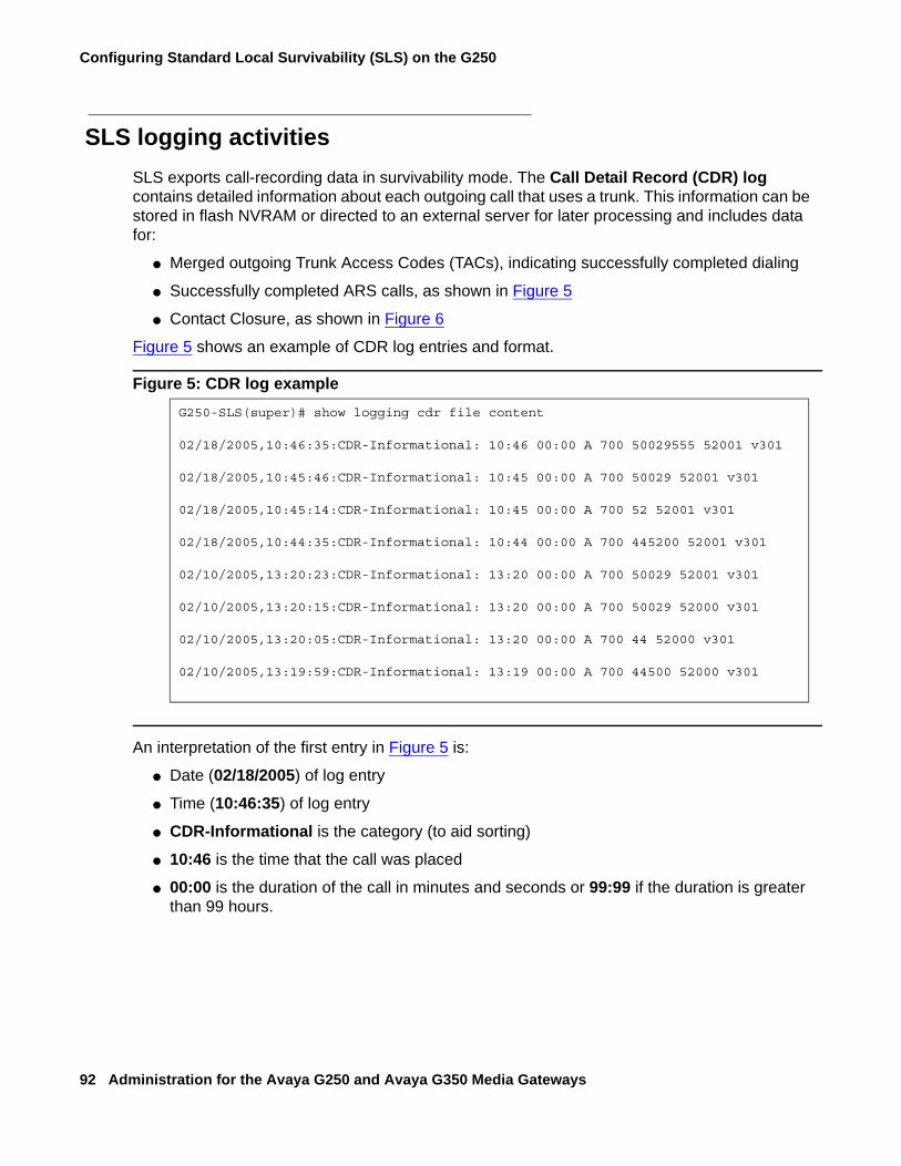
Configuring Standard Local Survivability (SLS) on the G250
92 Administration for the Avaya G250 and Avaya G350 Media Gateways
SLS logging activitiesSLS exports call-recording data in survivability mode. The Call Detail Record (CDR) log contains detailed information about each outgoing call that uses a trunk. This information can be stored in flash NVRAM or directed to an external server for later processing and includes data for:
● Merged outgoing Trunk Access Codes (TACs), indicating successfully completed dialing
● Successfully completed ARS calls, as shown in Figure 5
● Contact Closure, as shown in Figure 6
Figure 5 shows an example of CDR log entries and format.
Figure 5: CDR log example
An interpretation of the first entry in Figure 5 is:
● Date (02/18/2005) of log entry
● Time (10:46:35) of log entry
● CDR-Informational is the category (to aid sorting)
● 10:46 is the time that the call was placed
● 00:00 is the duration of the call in minutes and seconds or 99:99 if the duration is greater than 99 hours.
G250-SLS(super)# show logging cdr file content
02/18/2005,10:46:35:CDR-Informational: 10:46 00:00 A 700 50029555 52001 v301
02/18/2005,10:45:46:CDR-Informational: 10:45 00:00 A 700 50029 52001 v301
02/18/2005,10:45:14:CDR-Informational: 10:45 00:00 A 700 52 52001 v301
02/18/2005,10:44:35:CDR-Informational: 10:44 00:00 A 700 445200 52001 v301
02/10/2005,13:20:23:CDR-Informational: 13:20 00:00 A 700 50029 52001 v301
02/10/2005,13:20:15:CDR-Informational: 13:20 00:00 A 700 50029 52000 v301
02/10/2005,13:20:05:CDR-Informational: 13:20 00:00 A 700 44 52000 v301
02/10/2005,13:19:59:CDR-Informational: 13:19 00:00 A 700 44500 52000 v301
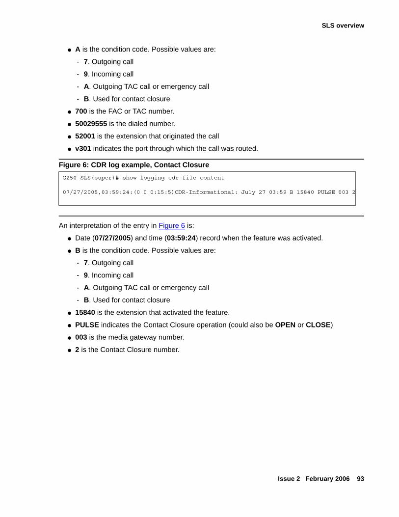
SLS overview
Issue 2 February 2006 93
● A is the condition code. Possible values are:
- 7. Outgoing call
- 9. Incoming call
- A. Outgoing TAC call or emergency call
- B. Used for contact closure
● 700 is the FAC or TAC number.
● 50029555 is the dialed number.
● 52001 is the extension that originated the call
● v301 indicates the port through which the call was routed.
Figure 6: CDR log example, Contact Closure
An interpretation of the entry in Figure 6 is:
● Date (07/27/2005) and time (03:59:24) record when the feature was activated.
● B is the condition code. Possible values are:
- 7. Outgoing call
- 9. Incoming call
- A. Outgoing TAC call or emergency call
- B. Used for contact closure
● 15840 is the extension that activated the feature.
● PULSE indicates the Contact Closure operation (could also be OPEN or CLOSE)
● 003 is the media gateway number.
● 2 is the Contact Closure number.
G250-SLS(super)# show logging cdr file content
07/27/2005,03:59:24:(0 0 0:15:5)CDR-Informational: July 27 03:59 B 15840 PULSE 003 2
Configuring Standard Local Survivability (SLS) on the G250
94 Administration for the Avaya G250 and Avaya G350 Media Gateways
Configuring SLSSLS is installed when the G250 is installed. However, for SLS to actually work, the following conditions must be satisfied:
● Provisioning data from the PIM tool must be gathered from Avaya Communication Manager and delivered to the G250 using PIM. If PIM is not available, the G250 can be manually configured for SLS and Auto Fallback via the CLI. See Gathering provisioning data from PIM for instructions on gathering and delivering the provisioning data. If PIM is not available, see Manually configuring the SLS data through the CLI.
● SLS must be enabled on the G250. See Enabling and disabling SLS on the G250.
● Avaya Communication Manager must be configured for SLS and Auto Fallback. For information about configuring SLS in Avaya Communication Manager, see “Network Recovery” in Maintenance Procedures for Avaya Communication Manager 3.0, Media Gateways and Servers, 03-300432.
Gathering provisioning data from PIMBefore enabling SLS, you must gather provisioning data from PIM and deliver it to the G250. Run PIM’s Device Profile Wizard to perform this task. The Device Profile Wizard gathers a subset of the Communication Manager translations (dial plan analysis and destination routing instructions) and delivers them to the G250. If PIM is not available, this translation subset (the SLS data set) can be created manually, using the procedure described in Manually configuring the SLS data through the CLI on page 99.
PIM must be installed on and launched from the Avaya Network Management Console. For information about PIM, see Accessing PIM on page 40.
From PIM’s Device Profile Wizard:
1. Use the Add ARS Dial String page (Figure 7) to administer an Automatic Route Selection in SLS.
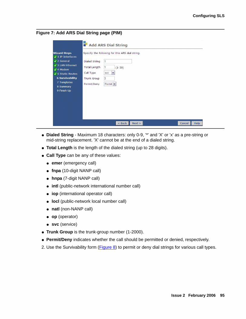
Configuring SLS
Issue 2 February 2006 95
Figure 7: Add ARS Dial String page (PIM)
● Dialed String - Maximum 18 characters: only 0-9, '*' and 'X' or 'x' as a pre-string or mid-string replacement. 'X' cannot be at the end of a dialed string.
● Total Length is the length of the dialed string (up to 28 digits).
● Call Type can be any of these values:
● emer (emergency call)
● fnpa (10-digit NANP call)
● hnpa (7-digit NANP call)
● intl (public-network international number call)
● iop (international operator call)
● locl (public-network local number call)
● natl (non-NANP call)
● op (operator)
● svc (service)
● Trunk Group is the trunk-group number (1-2000).
● Permit/Deny indicates whether the call should be permitted or denied, respectively.
2. Use the Survivability form (Figure 8) to permit or deny dial strings for various call types.
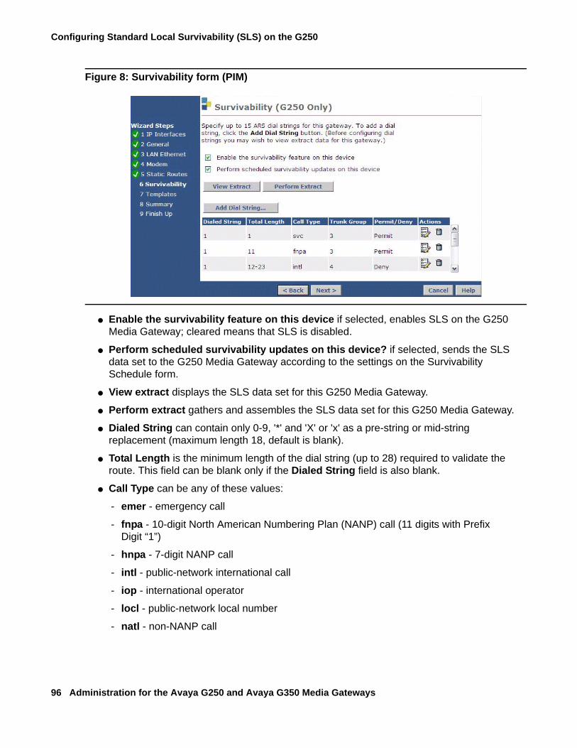
Configuring Standard Local Survivability (SLS) on the G250
96 Administration for the Avaya G250 and Avaya G350 Media Gateways
Figure 8: Survivability form (PIM)
● Enable the survivability feature on this device if selected, enables SLS on the G250 Media Gateway; cleared means that SLS is disabled.
● Perform scheduled survivability updates on this device? if selected, sends the SLS data set to the G250 Media Gateway according to the settings on the Survivability Schedule form.
● View extract displays the SLS data set for this G250 Media Gateway.
● Perform extract gathers and assembles the SLS data set for this G250 Media Gateway.
● Dialed String can contain only 0-9, '*' and 'X' or 'x' as a pre-string or mid-string replacement (maximum length 18, default is blank).
● Total Length is the minimum length of the dial string (up to 28) required to validate the route. This field can be blank only if the Dialed String field is also blank.
● Call Type can be any of these values:
- emer - emergency call
- fnpa - 10-digit North American Numbering Plan (NANP) call (11 digits with Prefix Digit “1”)
- hnpa - 7-digit NANP call
- intl - public-network international call
- iop - international operator
- locl - public-network local number
- natl - non-NANP call
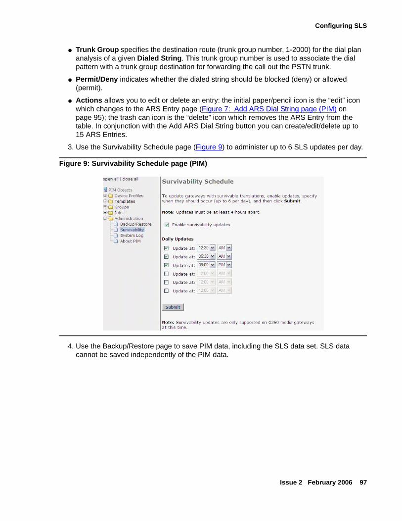
Configuring SLS
Issue 2 February 2006 97
● Trunk Group specifies the destination route (trunk group number, 1-2000) for the dial plan analysis of a given Dialed String. This trunk group number is used to associate the dial pattern with a trunk group destination for forwarding the call out the PSTN trunk.
● Permit/Deny indicates whether the dialed string should be blocked (deny) or allowed (permit).
● Actions allows you to edit or delete an entry: the initial paper/pencil icon is the “edit” icon which changes to the ARS Entry page (Figure 7: Add ARS Dial String page (PIM) on page 95); the trash can icon is the “delete” icon which removes the ARS Entry from the table. In conjunction with the Add ARS Dial String button you can create/edit/delete up to 15 ARS Entries.
3. Use the Survivability Schedule page (Figure 9) to administer up to 6 SLS updates per day.
Figure 9: Survivability Schedule page (PIM)
4. Use the Backup/Restore page to save PIM data, including the SLS data set. SLS data cannot be saved independently of the PIM data.
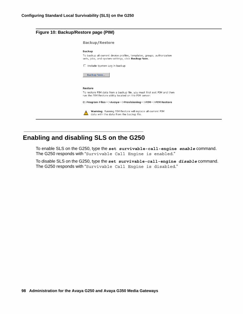
Configuring Standard Local Survivability (SLS) on the G250
98 Administration for the Avaya G250 and Avaya G350 Media Gateways
Figure 10: Backup/Restore page (PIM)
Enabling and disabling SLS on the G250To enable SLS on the G250, type the set survivable-call-engine enable command. The G250 responds with “Survivable Call Engine is enabled.”
To disable SLS on the G250, type the set survivable-call-engine disable command. The G250 responds with “Survivable Call Engine is disabled.”
Configuring SLS
Issue 2 February 2006 99
Manually configuring the SLS data through the CLIIt is recommended to use PIM to configure the SLS data. However, if PIM is unavailable, you can also configure the SLS data from the G250 itself using the G250 CLI.
Prerequisites
● Communication Manager Release 3.1 or later running on the host server
● PIM or configuration of the G250 through its CLI
● Registration of the G250 with Avaya Communication Manager
● SLS enabled on the G250 through its CLI
● No access to Communication Manager on the S8500 through the Processor Ethernet interface
● S8300 is not serving as a LSP
● G250 is not subtending to another external server (including ESS or another LSP in another gateway).
Configuring the SLS data
To create the SLS data set on the G250 using the CLI:
1. Type the survivable-call-engine command to enter survivable-call-engine context.
2. Type the station extension class command to enter the context of a station that you want to be covered by SLS, where:
● extension is a 1-7 digit numeric string, and
● class is the type of phone (analog, dcp, or ip)
For example:
● station 1234567 ip enters the context of an IP phone with the extension 1234567.
Note:Note: To remove a station from SLS coverage, type clear extension extension.
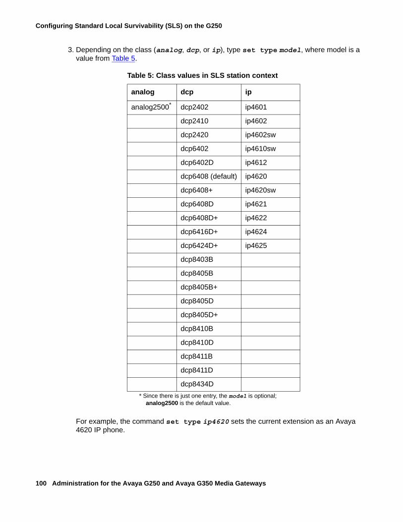
Configuring Standard Local Survivability (SLS) on the G250
100 Administration for the Avaya G250 and Avaya G350 Media Gateways
3. Depending on the class (analog, dcp, or ip), type set type model, where model is a value from Table 5.
For example, the command set type ip4620 sets the current extension as an Avaya 4620 IP phone.
Table 5: Class values in SLS station context
analog dcp ip
analog2500*
* Since there is just one entry, the model is optional; analog2500 is the default value.
dcp2402 ip4601
dcp2410 ip4602
dcp2420 ip4602sw
dcp6402 ip4610sw
dcp6402D ip4612
dcp6408 (default) ip4620
dcp6408+ ip4620sw
dcp6408D ip4621
dcp6408D+ ip4622
dcp6416D+ ip4624
dcp6424D+ ip4625
dcp8403B
dcp8405B
dcp8405B+
dcp8405D
dcp8405D+
dcp8410B
dcp8410D
dcp8411B
dcp8411D
dcp8434D
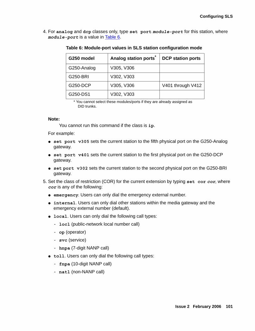
Configuring SLS
Issue 2 February 2006 101
4. For analog and dcp classes only, type set port module-port for this station, where module-port is a value in Table 6.
Note:Note: You cannot run this command if the class is ip.
For example:
● set port v305 sets the current station to the fifth physical port on the G250-Analog gateway.
● set port v401 sets the current station to the first physical port on the G250-DCP gateway.
● set port v302 sets the current station to the second physical port on the G250-BRI gateway.
5. Set the class of restriction (COR) for the current extension by typing set cor cor, where cor is any of the following:
● emergency. Users can only dial the emergency external number.
● internal. Users can only dial other stations within the media gateway and the emergency external number (default).
● local. Users can only dial the following call types:
- locl (public-network local number call)
- op (operator)
- svc (service)
- hnpa (7-digit NANP call)
● toll. Users can only dial the following call types:
- fnpa (10-digit NANP call)
- natl (non-NANP call)
Table 6: Module-port values in SLS station configuration mode
G250 model Analog station ports*
* You cannot select these modules/ports if they are already assigned as DID trunks.
DCP station ports
G250-Analog V305, V306
G250-BRI V302, V303
G250-DCP V305, V306 V401 through V412
G250-DS1 V302, V303
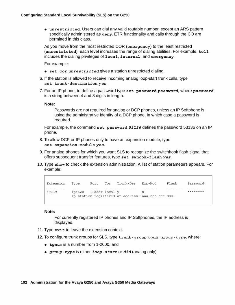
Configuring Standard Local Survivability (SLS) on the G250
102 Administration for the Avaya G250 and Avaya G350 Media Gateways
● unrestricted. Users can dial any valid routable number, except an ARS pattern specifically administered as deny. ETR functionality and calls through the CO are permitted in this class.
As you move from the most restricted COR (emergency) to the least restricted (unrestricted), each level increases the range of dialing abilities. For example, toll includes the dialing privileges of local, internal, and emergency.
For example:
● set cor unrestricted gives a station unrestricted dialing.
6. If the station is allowed to receive incoming analog loop-start trunk calls, type set trunk-destination yes.
7. For an IP phone, to define a password type set password password, where password is a string between 4 and 8 digits in length.
Note:Note: Passwords are not required for analog or DCP phones, unless an IP Softphone is
using the administrative identity of a DCP phone, in which case a password is required.
For example, the command set password 53136 defines the password 53136 on an IP phone.
8. To allow DCP or IP phones only to have an expansion module, type set expansion-module yes.
9. For analog phones for which you want SLS to recognize the switchhook flash signal that offers subsequent transfer features, type set swhook-flash yes.
10. Type show to check the extension administration. A list of station parameters appears. For example:
Note:Note: For currently registered IP phones and IP Softphones, the IP address is
displayed.
11. Type exit to leave the extension context.
12. To configure trunk groups for SLS, type trunk-group tgum group-type, where:
● tgnum is a number from 1-2000, and
● group-type is either loop-start or did (analog only)
Extension Type Port Cor Trunk-Des Exp-Mod Flash Password--------- ---- ---- ----- --------- ------- ------- --------49139 ip4620 IPaddr local y n - ******** ip station registered at address ‘aaa.bbb.ccc.ddd’
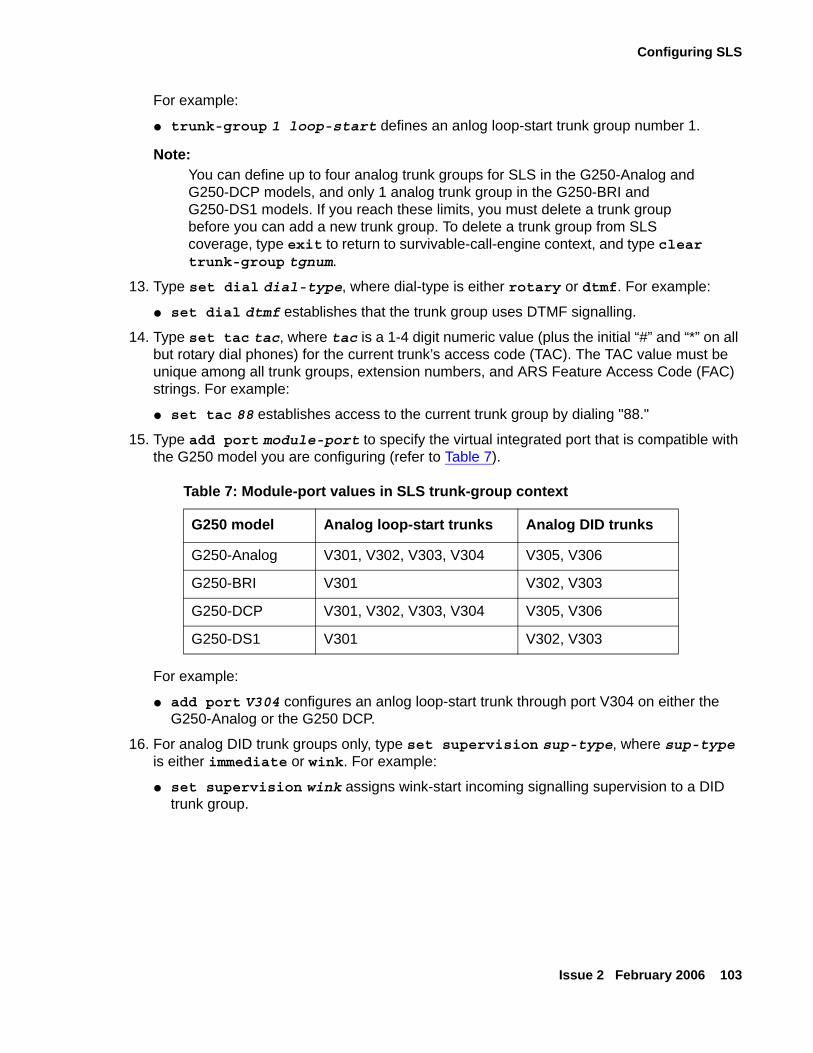
Configuring SLS
Issue 2 February 2006 103
For example:
● trunk-group 1 loop-start defines an anlog loop-start trunk group number 1.
Note:Note: You can define up to four analog trunk groups for SLS in the G250-Analog and
G250-DCP models, and only 1 analog trunk group in the G250-BRI and G250-DS1 models. If you reach these limits, you must delete a trunk group before you can add a new trunk group. To delete a trunk group from SLS coverage, type exit to return to survivable-call-engine context, and type clear trunk-group tgnum.
13. Type set dial dial-type, where dial-type is either rotary or dtmf. For example:
● set dial dtmf establishes that the trunk group uses DTMF signalling.
14. Type set tac tac, where tac is a 1-4 digit numeric value (plus the initial “#” and “*” on all but rotary dial phones) for the current trunk’s access code (TAC). The TAC value must be unique among all trunk groups, extension numbers, and ARS Feature Access Code (FAC) strings. For example:
● set tac 88 establishes access to the current trunk group by dialing "88."
15. Type add port module-port to specify the virtual integrated port that is compatible with the G250 model you are configuring (refer to Table 7).
For example:
● add port V304 configures an anlog loop-start trunk through port V304 on either the G250-Analog or the G250 DCP.
16. For analog DID trunk groups only, type set supervision sup-type, where sup-type is either immediate or wink. For example:
● set supervision wink assigns wink-start incoming signalling supervision to a DID trunk group.
Table 7: Module-port values in SLS trunk-group context
G250 model Analog loop-start trunks Analog DID trunks
G250-Analog V301, V302, V303, V304 V305, V306
G250-BRI V301 V302, V303
G250-DCP V301, V302, V303, V304 V305, V306
G250-DS1 V301 V302, V303
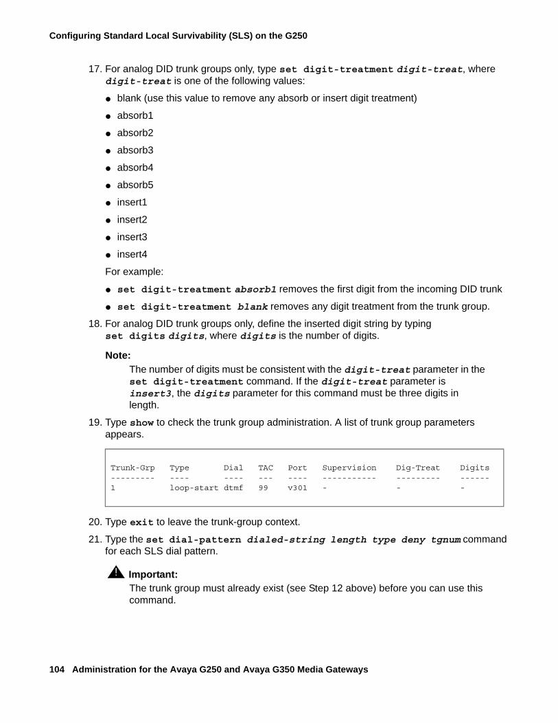
Configuring Standard Local Survivability (SLS) on the G250
104 Administration for the Avaya G250 and Avaya G350 Media Gateways
17. For analog DID trunk groups only, type set digit-treatment digit-treat, where digit-treat is one of the following values:
● blank (use this value to remove any absorb or insert digit treatment)
● absorb1
● absorb2
● absorb3
● absorb4
● absorb5
● insert1
● insert2
● insert3
● insert4
For example:
● set digit-treatment absorb1 removes the first digit from the incoming DID trunk
● set digit-treatment blank removes any digit treatment from the trunk group.
18. For analog DID trunk groups only, define the inserted digit string by typing set digits digits, where digits is the number of digits.
Note:Note: The number of digits must be consistent with the digit-treat parameter in the
set digit-treatment command. If the digit-treat parameter is insert3, the digits parameter for this command must be three digits in length.
19. Type show to check the trunk group administration. A list of trunk group parameters appears.
20. Type exit to leave the trunk-group context.
21. Type the set dial-pattern dialed-string length type deny tgnum command for each SLS dial pattern.
! Important:Important: The trunk group must already exist (see Step 12 above) before you can use this
command.
Trunk-Grp Type Dial TAC Port Supervision Dig-Treat Digits--------- ---- ---- --- ---- ----------- --------- ------1 loop-start dtmf 99 v301 - - -
Configuring SLS
Issue 2 February 2006 105
Examples● set dial-pattern 100 4 fnpa false 30
● set dial-pattern 200 4 fnpa false 30
22. Type the set fac feature fac command to set the Feature Access Code, where feature is any of the following:
● ars1
● ars2
● hold
● contact-open
● contact-close
● contact-pulse
and fac is a 1-4 digit string that includes the digits 0 through 9, excluding “*” and “#” for analog rotary phones. The fac string must be unique and must not conflict with station extension numbers and Trunk Access Codes (TACs). For example:
● set fac ars2 *9
● set fac contact-close 8
Note:Note: The “*” and “#” characters are not available on rotary-dial, analog phones.
23. Type the set-ip-codec-set command to select the country-specific G.711 codec (G.711mu or G.711a).
24. To change the maximum allowable IP registrations from the default (8), use the set max-ip-registrations n command, where n is between 1-12.
! Important:Important: Since the VoIP resources on the G250 are limited, adjusting the maximum IP
registrations above the default value can result in system performance problems.
25. Type the exit command to leave the survivable-call-engine context.
26. Type the set survivable-call-engine enable command to enable SLS on the G250 media gateway.
27. Type the copy running-config startup-config command to save the configuration changes.

Configuring Standard Local Survivability (SLS) on the G250
106 Administration for the Avaya G250 and Avaya G350 Media Gateways
Issue 2 February 2006 107
Chapter 6: Configuring Ethernet ports
This chapter provides information about configuring Ethernet ports on the Avaya G250 and G350 Media Gateways and contains the following sections:
● Ethernet ports on the G250 — a description of the Ethernet ports on the G250
● Ethernet ports on the G350 — a description of the Ethernet ports on the G350
● Configuring switch Ethernet ports — instructions on how to configure Ethernet ports on the G250 and G350 switches
● Configuring the WAN Ethernet port — instructions on how to configure the Ethernet port on the G250 and G350 routers
● Configuring DHCP client — instructions on how to configure DCHP client on the Fast Ethernet interface, for support of dynamic IP addressing
● Configuring LLDP — instructions on how to configure LLDP on the G250 and G350, and on Ethernet interfaces, to enable LLDP advertisements
Ethernet ports on the G250The switch on the Avaya G250 Media Gateway has the following Ethernet ports:
● Eight 10/100 mbps fixed switch ports on the front panel (ports 10/3 - 10/10)
Note:Note: The G250-DCP model only has two 10/100 mbps fixed switch ports on its front
panel.
The router on the Avaya G250 Media Gateway has the following Ethernet port:
● The 10/100 mbps fixed router port on the front panel (port 10/2)
Use a standard network cable when you connect one of the following devices to the fixed router port:
● WAN endpoint device
● Switch
● Router
Use a crossover network cable when you connect a computer or other endpoint device to the fixed router port. For the other Ethernet ports on the G250, you can use either a standard network cable or a crossover network cable to connect any device.
Configuring Ethernet ports
108 Administration for the Avaya G250 and Avaya G350 Media Gateways
Ethernet ports on the G350The switch on the Avaya G350 Media Gateway has the following Ethernet ports:
● The 10/100 mbps fixed switch port on the front panel (port 10/3)
● The 10/100 mbps ports on the Avaya MM314 Media Module (ports 6/1 through 6/24)
● The 10/100 mbps ports on the Avaya MM316 Media Module (ports 6/1 through 6/40)
● The Gigabit port on the Avaya MM314 or MM316 Media Module (port 6/51)
Note:Note: The ports on the Avaya MM314 or MM316 Media Module are only available if
your G350 includes one of these two media modules.
The router on the Avaya G350 Media Gateway has the following Ethernet port:
● The 10/100 mbps fixed router port on the front panel (port 10/2)
Use a standard network cable when you connect one of the following devices to the fixed router port:
● WAN endpoint device
● Switch
● Router
Use a crossover network cable when you connect a computer or other endpoint device to the fixed router port. For all other Ethernet ports on the G350, you can use either a standard network cable or a crossover network cable to connect any device.
Configuring switch Ethernet portsFor basic configuration of a switch Ethernet port, use the commands listed below. You can also configure the following features on a switch Ethernet port:
● Advanced switching features, including VLANs. For more information, see Chapter 16: Configuring advanced switching.
● VoIP queuing. To configure VoIP queuing on a switch port, configure a VLAN for the port. Then configure VoIP queuing on the VLAN. For more information about VoIP queuing, see Configuring QoS parameters on page 138.
Configuring switch Ethernet ports
Issue 2 February 2006 109
● Access control policy lists and QoS policy lists. To configure policy lists on a switch port, configure a VLAN for the port. Then configure policy on the VLAN. For more information on policy lists, see Chapter 20: Configuring policy.
● SNMP Link Up and Link Down traps. For more information, see Configuring SNMP traps on page 225.
Switch Ethernet port commandsUse the following commands for basic configuration of switch Ethernet ports. For more information about these commands, see Avaya G250 and Avaya G350 CLI Reference, 03-300437.
● Use the set port auto-negotiation-flowcontrol-advertisement command to set the flowcontrol advertisement for the specified port when performing auto-negotiation. This command is only applicable to the Gigabit Ethernet port.
● Use the set port disable command to disable a port or range of ports.
● Use the set port duplex command to configure the duplex type of an Ethernet or Fast Ethernet port or range of ports.You can configure Ethernet and Fast Ethernet interfaces to either full duplex or half duplex. The duplex status of a port in auto-negotiation mode is determined by auto-negotiation. When auto-negotiation is enabled, an error message is generated if you attempt to set the transmission type of auto-negotiation Fast Ethernet ports to half-duplex or full-duplex mode.
● Use the set port edge admin state command to determine whether or not the port is an edge port. Edge port is a treatment assigned to ports for the purposes of RSTP (Rapid Spanning Tree Protocol). For more information about using this command and RSTP configuration in general, see Rapid Spanning Tree Protocol (RSTP) on page 253.
Note:Note: This command is not supported by the G250.
● Use the set port enable command to enable a port or a range of ports.
● Use the set port level command to determine the default packet priority level for untagged packets. Packets traveling through a port set at normal priority should be served only after packets traveling through a port set at high priority are served.
● Use the set port name command to configure a name for a port.
● Use the set port negotiation command to enable or disable the link negotiation protocol on the specified port. This command applies to Fast Ethernet or Gigabit Ethernet ports. When negotiation is enabled, the speed and duplex of the Fast Ethernet ports are determined by auto-negotiation. If negotiation is disabled, the user can set the speed and duplex of the Fast Ethernet ports.
Configuring Ethernet ports
110 Administration for the Avaya G250 and Avaya G350 Media Gateways
● Use the set port point-to-point admin status command, followed by the module and port number of the port, to manage the connection type of the port. Use one of the following arguments with this command:
- force-true — the port is treated as if it were connected point-to-point
- force-false — the port is treated as if it were connected to shared media
- auto — the G350 tries to automatically detect the connection type of the port
Note:Note: This command is not supported by the G250.
● Use the set port speed command to configure the speed of a port or range of ports. In auto-negotiation mode, the port’s speed is determined by auto-negotiation. An error message is generated if you attempt to set the speed when auto-negotiation is enabled
Configuring the WAN Ethernet portFor basic configuration of the WAN Ethernet port:
1. Use the interface FastEthernet 10/2 command to enter the context of the port interface.
2. Perform basic configuration of the interface. For more information, see Configuring interfaces on page 334.
3. Use the Ethernet WAN port configuration commands in the context of the port interface. See WAN Ethernet port commands on page 111.
You can also configure the following features on the WAN Ethernet port:
● Primary Management Interface (PMI). For more information, see Configuring the Primary Management Interface (PMI) on page 66.
● Advanced router features. For more information, see Chapter 18: Configuring the router.
● VoIP queuing. For more information, see Configuring QoS parameters on page 138.
● Access control policy lists and QoS policy lists. For more information, see Chapter 20: Configuring policy.
● SNMP Link Up and Link Down traps. For more information, see Configuring SNMP traps on page 225.
Configuring the WAN Ethernet port
Issue 2 February 2006 111
WAN Ethernet port traffic shapingYou can use traffic shaping to determine the data transfer rate on the WAN Ethernet port. To set traffic shaping, use the traffic-shape rate command in the interface context. Traffic shaping works in tandem with the configured bandwidth. If you change the traffic shape rate, this automatically changes the bandwidth. Similarly, if you change the bandwidth, this automatically changes the traffic shape rate.
Note:Note: The traffic shape rate is determined in bits. The bandwidth is determined in
kilobytes.
To disable traffic shaping, use the no form of the traffic-shape rate command.
For information on traffic shaping in general, see Configuring QoS parameters on page 138.
Backup interfacesYou can configure backup relations between a pair of any Layer 2 serial interfaces, including the Fast Ethernet interface. For instructions on how to configure backup interfaces, see Backup interfaces on page 162.
WAN Ethernet port commandsUse the following commands in FastEthernet 10/2 context for basic Ethernet configuration of the WAN Ethernet port:
● Use the autoneg command to set the port speed and duplex to auto-negotiation mode for the external Fast Ethernet port. Use the no form of this command to disable the auto-negotiation mode.
● Use the duplex command to control the duplex setting for the interface.
● Use the shutdown command to set the administrative status of the current interface to down. Use the no form of this command to restore the administrative status of the interface to up.
● Use the speed command to set the port speed.
Configuring Ethernet ports
112 Administration for the Avaya G250 and Avaya G350 Media Gateways
Configuring DHCP clientThis section provides information about configuring DHCP client in the G250/G350, and contains the following topics:
● DHCP client overview
● DHCP client applications
● DHCP client configuration
● Releasing and renewing a DHCP lease
● Maintaining DHCP client
● Configuring DHCP client logging messages
DHCP client overviewThe Avaya G250/G350 Media Gateway can be configured to function as a DHCP (Dynamic Host Configuration Protocol) client. DHCP client enables the G250/G350 to receive an IP address from a DHCP server, according to the DHCP client-server protocol. The DHCP server grants the G250/G350 DHCP client an IP address for a fixed amount of time, called the lease. After the lease expires, the G250/G350 DHCP client is required to stop using the IP address. The G250/G350 DHCP client periodically sends requests to the server to renew or extend the lease. In addition to receiving an IP address, a G250/G350 DHCP client can optionally request to receive a domain name, a list of default routers, and a list of available DNS servers.
Note:Note: The Avaya G250/G350 Media Gateway can function as both a DHCP server and
a DHCP client simultaneously. That is, you can connect a cable modem for an Internet connection to the WAN fast Ethernet in order to use the G250/G350 as a DHCP client. At the same time, you can activate the DHCP server on the G250/G350 for use by clients such as IP phones and PCs connected to the LAN ports. The DHCP server on the G250/G350 does not serve Internet devices connected over the WAN Fast Ethernet port.
For information on configuring the G250/G350 as a DHCP server, see Configuring DHCP server on page 355.
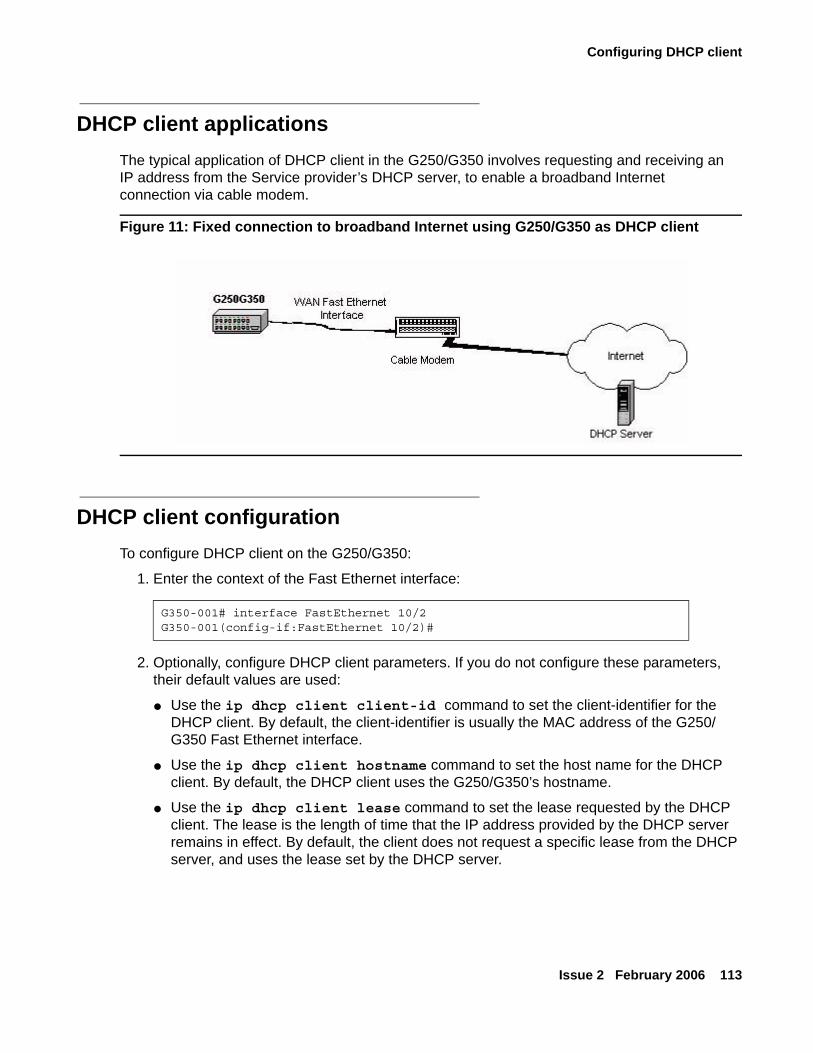
Configuring DHCP client
Issue 2 February 2006 113
DHCP client applicationsThe typical application of DHCP client in the G250/G350 involves requesting and receiving an IP address from the Service provider’s DHCP server, to enable a broadband Internet connection via cable modem.
Figure 11: Fixed connection to broadband Internet using G250/G350 as DHCP client
DHCP client configurationTo configure DHCP client on the G250/G350:
1. Enter the context of the Fast Ethernet interface:
2. Optionally, configure DHCP client parameters. If you do not configure these parameters, their default values are used:
● Use the ip dhcp client client-id command to set the client-identifier for the DHCP client. By default, the client-identifier is usually the MAC address of the G250/G350 Fast Ethernet interface.
● Use the ip dhcp client hostname command to set the host name for the DHCP client. By default, the DHCP client uses the G250/G350’s hostname.
● Use the ip dhcp client lease command to set the lease requested by the DHCP client. The lease is the length of time that the IP address provided by the DHCP server remains in effect. By default, the client does not request a specific lease from the DHCP server, and uses the lease set by the DHCP server.
G350-001# interface FastEthernet 10/2G350-001(config-if:FastEthernet 10/2)#
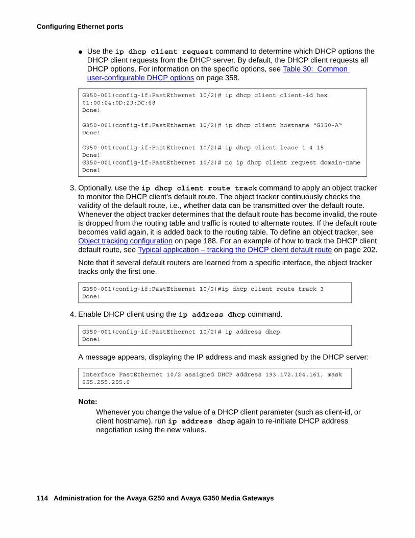
Configuring Ethernet ports
114 Administration for the Avaya G250 and Avaya G350 Media Gateways
● Use the ip dhcp client request command to determine which DHCP options the DHCP client requests from the DHCP server. By default, the DHCP client requests all DHCP options. For information on the specific options, see Table 30: Common user-configurable DHCP options on page 358.
3. Optionally, use the ip dhcp client route track command to apply an object tracker to monitor the DHCP client’s default route. The object tracker continuously checks the validity of the default route, i.e., whether data can be transmitted over the default route. Whenever the object tracker determines that the default route has become invalid, the route is dropped from the routing table and traffic is routed to alternate routes. If the default route becomes valid again, it is added back to the routing table. To define an object tracker, see Object tracking configuration on page 188. For an example of how to track the DHCP client default route, see Typical application – tracking the DHCP client default route on page 202.
Note that if several default routers are learned from a specific interface, the object tracker tracks only the first one.
4. Enable DHCP client using the ip address dhcp command.
A message appears, displaying the IP address and mask assigned by the DHCP server:
Note:Note: Whenever you change the value of a DHCP client parameter (such as client-id, or
client hostname), run ip address dhcp again to re-initiate DHCP address negotiation using the new values.
G350-001(config-if:FastEthernet 10/2)# ip dhcp client client-id hex 01:00:04:0D:29:DC:68Done!
G350-001(config-if:FastEthernet 10/2)# ip dhcp client hostname “G350-A“Done!
G350-001(config-if:FastEthernet 10/2)# ip dhcp client lease 1 4 15Done!G350-001(config-if:FastEthernet 10/2)# no ip dhcp client request domain-nameDone!
G350-001(config-if:FastEthernet 10/2)#ip dhcp client route track 3Done!
G350-001(config-if:FastEthernet 10/2)# ip address dhcpDone!
Interface FastEthernet 10/2 assigned DHCP address 193.172.104.161, mask 255.255.255.0
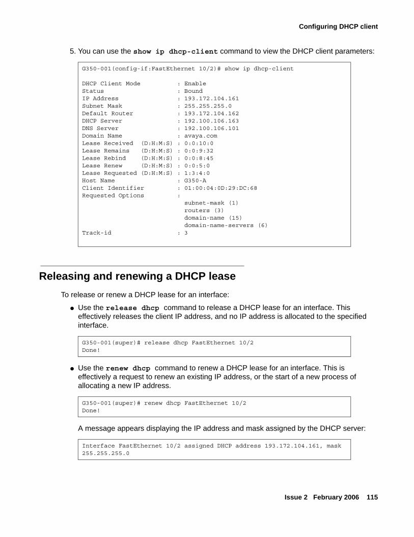
Configuring DHCP client
Issue 2 February 2006 115
5. You can use the show ip dhcp-client command to view the DHCP client parameters:
Releasing and renewing a DHCP leaseTo release or renew a DHCP lease for an interface:
● Use the release dhcp command to release a DHCP lease for an interface. This effectively releases the client IP address, and no IP address is allocated to the specified interface.
● Use the renew dhcp command to renew a DHCP lease for an interface. This is effectively a request to renew an existing IP address, or the start of a new process of allocating a new IP address.
A message appears displaying the IP address and mask assigned by the DHCP server:
G350-001(config-if:FastEthernet 10/2)# show ip dhcp-client
DHCP Client Mode : EnableStatus : BoundIP Address : 193.172.104.161Subnet Mask : 255.255.255.0Default Router : 193.172.104.162DHCP Server : 192.100.106.163DNS Server : 192.100.106.101Domain Name : avaya.comLease Received (D:H:M:S) : 0:0:10:0Lease Remains (D:H:M:S) : 0:0:9:32Lease Rebind (D:H:M:S) : 0:0:8:45Lease Renew (D:H:M:S) : 0:0:5:0Lease Requested (D:H:M:S) : 1:3:4:0Host Name : G350-AClient Identifier : 01:00:04:0D:29:DC:68Requested Options : subnet-mask (1) routers (3) domain-name (15) domain-name-servers (6)Track-id : 3
G350-001(super)# release dhcp FastEthernet 10/2Done!
G350-001(super)# renew dhcp FastEthernet 10/2Done!
Interface FastEthernet 10/2 assigned DHCP address 193.172.104.161, mask 255.255.255.0
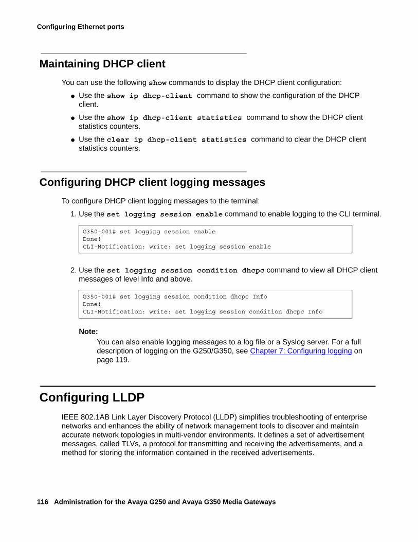
Configuring Ethernet ports
116 Administration for the Avaya G250 and Avaya G350 Media Gateways
Maintaining DHCP clientYou can use the following show commands to display the DHCP client configuration:
● Use the show ip dhcp-client command to show the configuration of the DHCP client.
● Use the show ip dhcp-client statistics command to show the DHCP client statistics counters.
● Use the clear ip dhcp-client statistics command to clear the DHCP client statistics counters.
Configuring DHCP client logging messagesTo configure DHCP client logging messages to the terminal:
1. Use the set logging session enable command to enable logging to the CLI terminal.
2. Use the set logging session condition dhcpc command to view all DHCP client messages of level Info and above.
Note:Note: You can also enable logging messages to a log file or a Syslog server. For a full
description of logging on the G250/G350, see Chapter 7: Configuring logging on page 119.
Configuring LLDPIEEE 802.1AB Link Layer Discovery Protocol (LLDP) simplifies troubleshooting of enterprise networks and enhances the ability of network management tools to discover and maintain accurate network topologies in multi-vendor environments. It defines a set of advertisement messages, called TLVs, a protocol for transmitting and receiving the advertisements, and a method for storing the information contained in the received advertisements.
G350-001# set logging session enableDone!CLI-Notification: write: set logging session enable
G350-001# set logging session condition dhcpc InfoDone!CLI-Notification: write: set logging session condition dhcpc Info
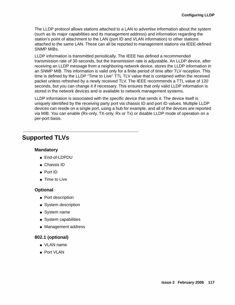
Configuring LLDP
Issue 2 February 2006 117
The LLDP protocol allows stations attached to a LAN to advertise information about the system (such as its major capabilities and its management address) and information regarding the station’s point of attachment to the LAN (port ID and VLAN information) to other stations attached to the same LAN. These can all be reported to management stations via IEEE-defined SNMP MIBs.LLDP information is transmitted periodically. The IEEE has defined a recommended transmission rate of 30 seconds, but the transmission rate is adjustable. An LLDP device, after receiving an LLDP message from a neighboring network device, stores the LLDP information in an SNMP MIB. This information is valid only for a finite period of time after TLV reception. This time is defined by the LLDP “Time to Live” TTL TLV value that is contained within the received packet unless refreshed by a newly received TLV. The IEEE recommends a TTL value of 120 seconds, but you can change it if necessary. This ensures that only valid LLDP information is stored in the network devices and is available to network management systems.
LLDP information is associated with the specific device that sends it. The device itself is uniquely identified by the receiving party port via chassis ID and port ID values. Multiple LLDP devices can reside on a single port, using a hub for example, and all of the devices are reported via MIB. You can enable (Rx-only, TX-only, Rx or Tx) or disable LLDP mode of operation on a per-port basis.
Supported TLVs
Mandatory● End-of-LDPDU
● Chassis ID
● Port ID
● Time to Live
Optional● Port description
● System description
● System name
● System capabilities
● Management address
802.1 (optional)● VLAN name
● Port VLAN
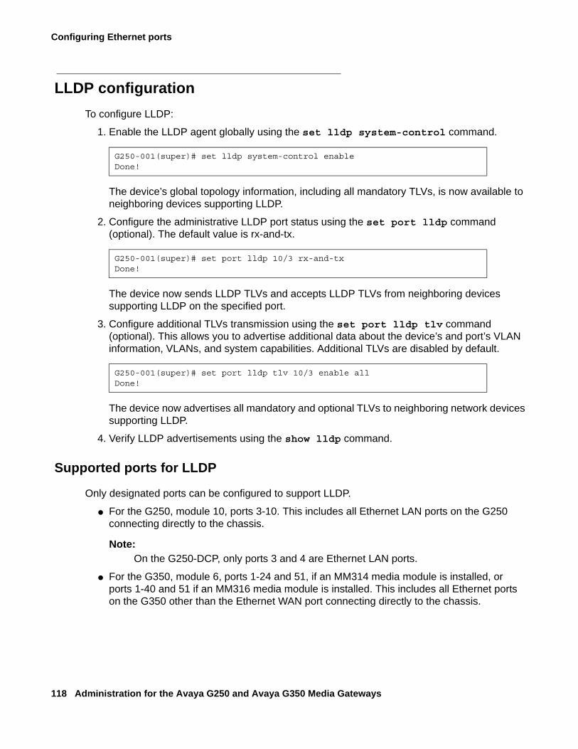
Configuring Ethernet ports
118 Administration for the Avaya G250 and Avaya G350 Media Gateways
LLDP configurationTo configure LLDP:
1. Enable the LLDP agent globally using the set lldp system-control command.
The device’s global topology information, including all mandatory TLVs, is now available to neighboring devices supporting LLDP.
2. Configure the administrative LLDP port status using the set port lldp command (optional). The default value is rx-and-tx.
The device now sends LLDP TLVs and accepts LLDP TLVs from neighboring devices supporting LLDP on the specified port.
3. Configure additional TLVs transmission using the set port lldp tlv command (optional). This allows you to advertise additional data about the device’s and port’s VLAN information, VLANs, and system capabilities. Additional TLVs are disabled by default.
The device now advertises all mandatory and optional TLVs to neighboring network devices supporting LLDP.
4. Verify LLDP advertisements using the show lldp command.
Supported ports for LLDP
Only designated ports can be configured to support LLDP.
● For the G250, module 10, ports 3-10. This includes all Ethernet LAN ports on the G250 connecting directly to the chassis.
Note:Note: On the G250-DCP, only ports 3 and 4 are Ethernet LAN ports.
● For the G350, module 6, ports 1-24 and 51, if an MM314 media module is installed, or ports 1-40 and 51 if an MM316 media module is installed. This includes all Ethernet ports on the G350 other than the Ethernet WAN port connecting directly to the chassis.
G250-001(super)# set lldp system-control enableDone!
G250-001(super)# set port lldp 10/3 rx-and-txDone!
G250-001(super)# set port lldp tlv 10/3 enable allDone!
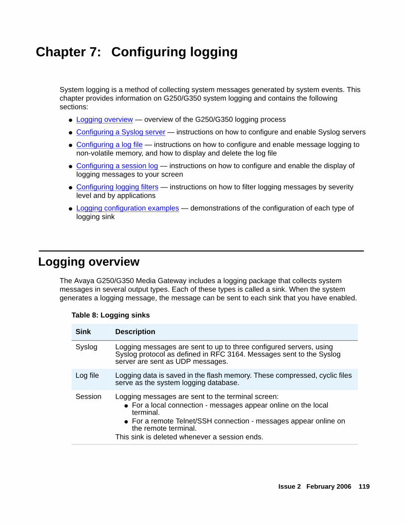
Issue 2 February 2006 119
Chapter 7: Configuring logging
System logging is a method of collecting system messages generated by system events. This chapter provides information on G250/G350 system logging and contains the following sections:
● Logging overview — overview of the G250/G350 logging process
● Configuring a Syslog server — instructions on how to configure and enable Syslog servers
● Configuring a log file — instructions on how to configure and enable message logging to non-volatile memory, and how to display and delete the log file
● Configuring a session log — instructions on how to configure and enable the display of logging messages to your screen
● Configuring logging filters — instructions on how to filter logging messages by severity level and by applications
● Logging configuration examples — demonstrations of the configuration of each type of logging sink
Logging overviewThe Avaya G250/G350 Media Gateway includes a logging package that collects system messages in several output types. Each of these types is called a sink. When the system generates a logging message, the message can be sent to each sink that you have enabled.
Table 8: Logging sinks
Sink Description
Syslog Logging messages are sent to up to three configured servers, using Syslog protocol as defined in RFC 3164. Messages sent to the Syslog server are sent as UDP messages.
Log file Logging data is saved in the flash memory. These compressed, cyclic files serve as the system logging database.
Session Logging messages are sent to the terminal screen:● For a local connection - messages appear online on the local
terminal.● For a remote Telnet/SSH connection - messages appear online on
the remote terminal.This sink is deleted whenever a session ends.
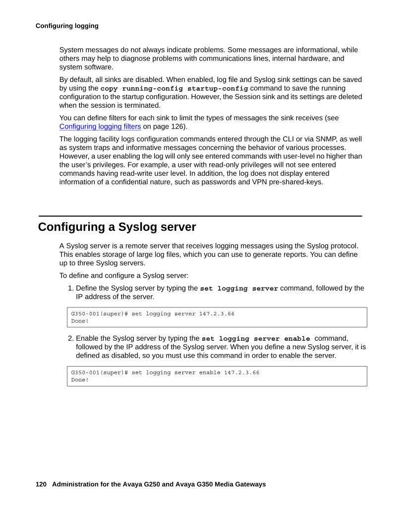
Configuring logging
120 Administration for the Avaya G250 and Avaya G350 Media Gateways
System messages do not always indicate problems. Some messages are informational, while others may help to diagnose problems with communications lines, internal hardware, and system software.
By default, all sinks are disabled. When enabled, log file and Syslog sink settings can be saved by using the copy running-config startup-config command to save the running configuration to the startup configuration. However, the Session sink and its settings are deleted when the session is terminated.
You can define filters for each sink to limit the types of messages the sink receives (see Configuring logging filters on page 126).
The logging facility logs configuration commands entered through the CLI or via SNMP, as well as system traps and informative messages concerning the behavior of various processes. However, a user enabling the log will only see entered commands with user-level no higher than the user’s privileges. For example, a user with read-only privileges will not see entered commands having read-write user level. In addition, the log does not display entered information of a confidential nature, such as passwords and VPN pre-shared-keys.
Configuring a Syslog serverA Syslog server is a remote server that receives logging messages using the Syslog protocol. This enables storage of large log files, which you can use to generate reports. You can define up to three Syslog servers.
To define and configure a Syslog server:
1. Define the Syslog server by typing the set logging server command, followed by the IP address of the server.
2. Enable the Syslog server by typing the set logging server enable command, followed by the IP address of the Syslog server. When you define a new Syslog server, it is defined as disabled, so you must use this command in order to enable the server.
G350-001(super)# set logging server 147.2.3.66Done!
G350-001(super)# set logging server enable 147.2.3.66Done!
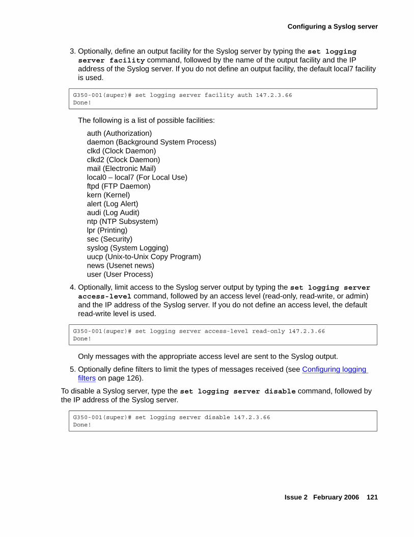
Configuring a Syslog server
Issue 2 February 2006 121
3. Optionally, define an output facility for the Syslog server by typing the set logging server facility command, followed by the name of the output facility and the IP address of the Syslog server. If you do not define an output facility, the default local7 facility is used.
The following is a list of possible facilities:
auth (Authorization)daemon (Background System Process)clkd (Clock Daemon)clkd2 (Clock Daemon)mail (Electronic Mail)local0 – local7 (For Local Use)ftpd (FTP Daemon)kern (Kernel)alert (Log Alert)audi (Log Audit)ntp (NTP Subsystem)lpr (Printing)sec (Security)syslog (System Logging)uucp (Unix-to-Unix Copy Program)news (Usenet news)user (User Process)
4. Optionally, limit access to the Syslog server output by typing the set logging server access-level command, followed by an access level (read-only, read-write, or admin) and the IP address of the Syslog server. If you do not define an access level, the default read-write level is used.
Only messages with the appropriate access level are sent to the Syslog output.
5. Optionally define filters to limit the types of messages received (see Configuring logging filters on page 126).
To disable a Syslog server, type the set logging server disable command, followed by the IP address of the Syslog server.
G350-001(super)# set logging server facility auth 147.2.3.66Done!
G350-001(super)# set logging server access-level read-only 147.2.3.66Done!
G350-001(super)# set logging server disable 147.2.3.66Done!
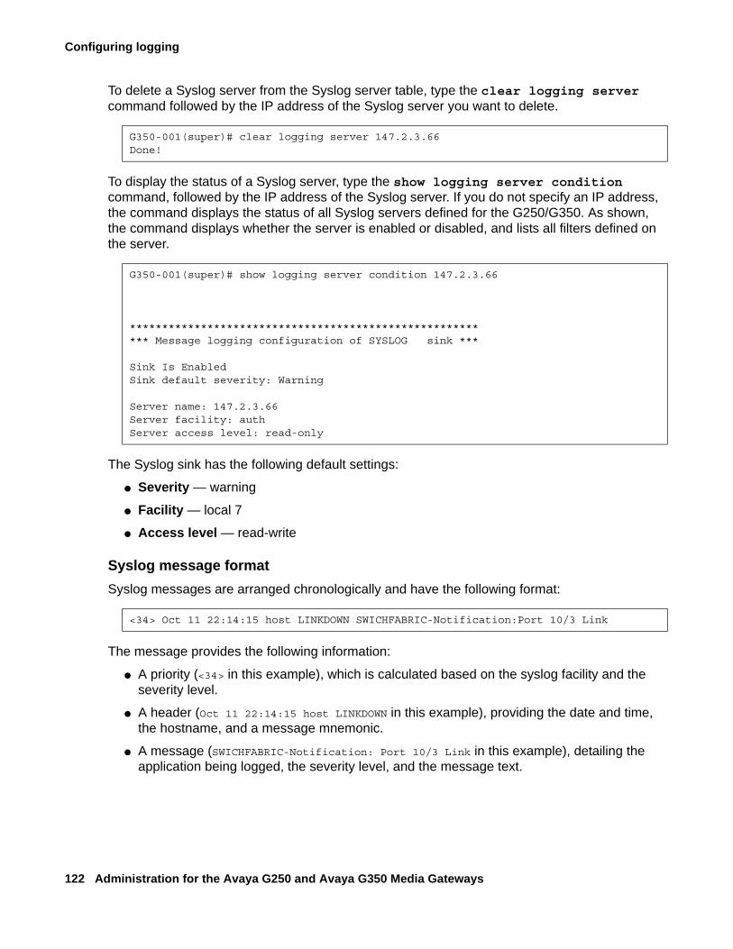
Configuring logging
122 Administration for the Avaya G250 and Avaya G350 Media Gateways
To delete a Syslog server from the Syslog server table, type the clear logging server command followed by the IP address of the Syslog server you want to delete.
To display the status of a Syslog server, type the show logging server condition command, followed by the IP address of the Syslog server. If you do not specify an IP address, the command displays the status of all Syslog servers defined for the G250/G350. As shown, the command displays whether the server is enabled or disabled, and lists all filters defined on the server.
The Syslog sink has the following default settings:
● Severity — warning
● Facility — local 7
● Access level — read-write
Syslog message formatSyslog messages are arranged chronologically and have the following format:
The message provides the following information:
● A priority (<34> in this example), which is calculated based on the syslog facility and the severity level.
● A header (Oct 11 22:14:15 host LINKDOWN in this example), providing the date and time, the hostname, and a message mnemonic.
● A message (SWICHFABRIC-Notification: Port 10/3 Link in this example), detailing the application being logged, the severity level, and the message text.
G350-001(super)# clear logging server 147.2.3.66Done!
G350-001(super)# show logging server condition 147.2.3.66
********************************************************* Message logging configuration of SYSLOG sink ***
Sink Is EnabledSink default severity: Warning
Server name: 147.2.3.66Server facility: authServer access level: read-only
<34> Oct 11 22:14:15 host LINKDOWN SWICHFABRIC-Notification:Port 10/3 Link
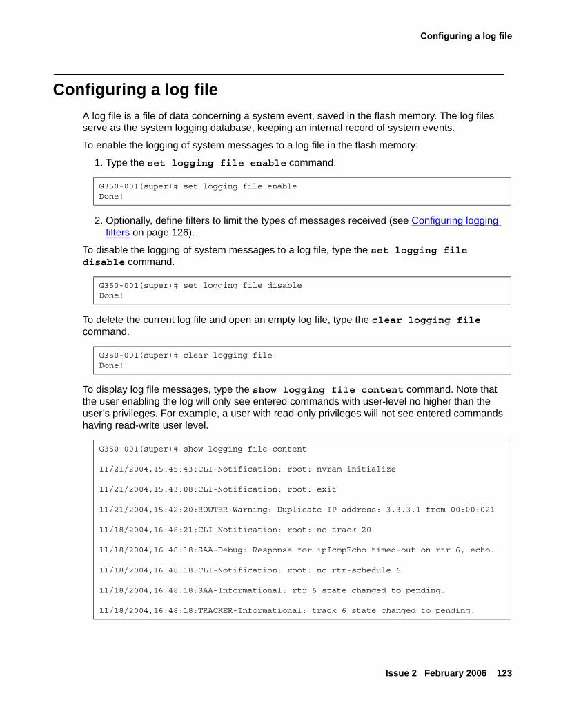
Configuring a log file
Issue 2 February 2006 123
Configuring a log fileA log file is a file of data concerning a system event, saved in the flash memory. The log files serve as the system logging database, keeping an internal record of system events.
To enable the logging of system messages to a log file in the flash memory:
1. Type the set logging file enable command.
2. Optionally, define filters to limit the types of messages received (see Configuring logging filters on page 126).
To disable the logging of system messages to a log file, type the set logging file disable command.
To delete the current log file and open an empty log file, type the clear logging file command.
To display log file messages, type the show logging file content command. Note that the user enabling the log will only see entered commands with user-level no higher than the user’s privileges. For example, a user with read-only privileges will not see entered commands having read-write user level.
G350-001(super)# set logging file enableDone!
G350-001(super)# set logging file disableDone!
G350-001(super)# clear logging fileDone!
G350-001(super)# show logging file content
11/21/2004,15:45:43:CLI-Notification: root: nvram initialize
11/21/2004,15:43:08:CLI-Notification: root: exit
11/21/2004,15:42:20:ROUTER-Warning: Duplicate IP address: 3.3.3.1 from 00:00:021
11/18/2004,16:48:21:CLI-Notification: root: no track 20
11/18/2004,16:48:18:SAA-Debug: Response for ipIcmpEcho timed-out on rtr 6, echo.
11/18/2004,16:48:18:CLI-Notification: root: no rtr-schedule 6
11/18/2004,16:48:18:SAA-Informational: rtr 6 state changed to pending.
11/18/2004,16:48:18:TRACKER-Informational: track 6 state changed to pending.
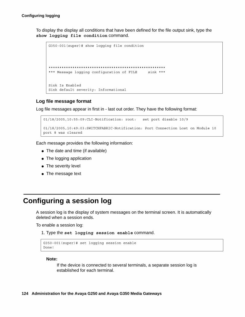
Configuring logging
124 Administration for the Avaya G250 and Avaya G350 Media Gateways
To display the display all conditions that have been defined for the file output sink, type the show logging file condition command.
Log file message formatLog file messages appear in first in - last out order. They have the following format:
Each message provides the following information:
● The date and time (if available)
● The logging application
● The severity level
● The message text
Configuring a session logA session log is the display of system messages on the terminal screen. It is automatically deleted when a session ends.
To enable a session log:
1. Type the set logging session enable command.
Note:Note: If the device is connected to several terminals, a separate session log is
established for each terminal.
G350-001(super)# show logging file condition
********************************************************* Message logging configuration of FILE sink ***
Sink Is EnabledSink default severity: Informational
01/18/2005,10:55:09:CLI-Notification: root: set port disable 10/9
01/18/2005,10:49:03:SWITCHFABRIC-Notification: Port Connection Lost on Module 10 port 8 was cleared
G350-001(super)# set logging session enableDone!
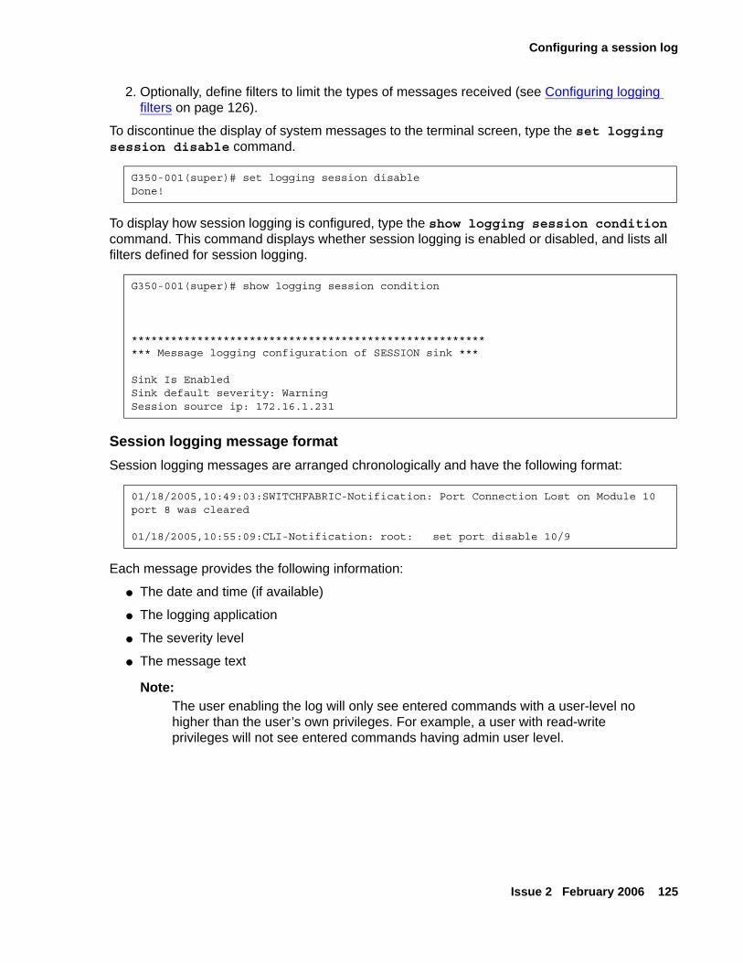
Configuring a session log
Issue 2 February 2006 125
2. Optionally, define filters to limit the types of messages received (see Configuring logging filters on page 126).
To discontinue the display of system messages to the terminal screen, type the set logging session disable command.
To display how session logging is configured, type the show logging session condition command. This command displays whether session logging is enabled or disabled, and lists all filters defined for session logging.
Session logging message formatSession logging messages are arranged chronologically and have the following format:
Each message provides the following information:
● The date and time (if available)
● The logging application
● The severity level
● The message text
Note:Note: The user enabling the log will only see entered commands with a user-level no
higher than the user’s own privileges. For example, a user with read-write privileges will not see entered commands having admin user level.
G350-001(super)# set logging session disableDone!
G350-001(super)# show logging session condition
********************************************************* Message logging configuration of SESSION sink ***
Sink Is EnabledSink default severity: WarningSession source ip: 172.16.1.231
01/18/2005,10:49:03:SWITCHFABRIC-Notification: Port Connection Lost on Module 10 port 8 was cleared
01/18/2005,10:55:09:CLI-Notification: root: set port disable 10/9
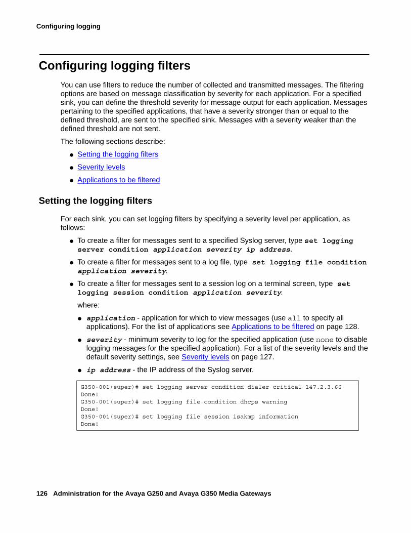
Configuring logging
126 Administration for the Avaya G250 and Avaya G350 Media Gateways
Configuring logging filtersYou can use filters to reduce the number of collected and transmitted messages. The filtering options are based on message classification by severity for each application. For a specified sink, you can define the threshold severity for message output for each application. Messages pertaining to the specified applications, that have a severity stronger than or equal to the defined threshold, are sent to the specified sink. Messages with a severity weaker than the defined threshold are not sent.
The following sections describe:
● Setting the logging filters
● Severity levels
● Applications to be filtered
Setting the logging filters
For each sink, you can set logging filters by specifying a severity level per application, as follows:
● To create a filter for messages sent to a specified Syslog server, type set logging server condition application severity ip address.
● To create a filter for messages sent to a log file, type set logging file condition application severity.
● To create a filter for messages sent to a session log on a terminal screen, type set logging session condition application severity.
where:
● application - application for which to view messages (use all to specify all applications). For the list of applications see Applications to be filtered on page 128.
● severity - minimum severity to log for the specified application (use none to disable logging messages for the specified application). For a list of the severity levels and the default severity settings, see Severity levels on page 127.
● ip address - the IP address of the Syslog server.
G350-001(super)# set logging server condition dialer critical 147.2.3.66Done!G350-001(super)# set logging file condition dhcps warningDone!G350-001(super)# set logging file session isakmp informationDone!
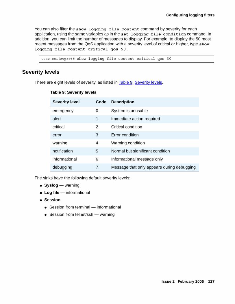
Configuring logging filters
Issue 2 February 2006 127
You can also filter the show logging file content command by severity for each application, using the same variables as in the set logging file condition command. In addition, you can limit the number of messages to display. For example, to display the 50 most recent messages from the QoS application with a severity level of critical or higher, type show logging file content critical qos 50.
Severity levels
There are eight levels of severity, as listed in Table 9, Severity levels.
The sinks have the following default severity levels:
● Syslog — warning
● Log file — informational
● Session● Session from terminal — informational
● Session from telnet/ssh — warning
G350-001(super)# show logging file content critical qos 50
Table 9: Severity levels
Severity level Code Description
emergency 0 System is unusable
alert 1 Immediate action required
critical 2 Critical condition
error 3 Error condition
warning 4 Warning condition
notification 5 Normal but significant condition
informational 6 Informational message only
debugging 7 Message that only appears during debugging
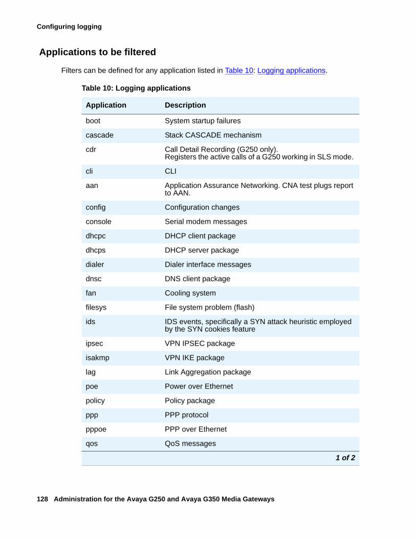
Configuring logging
128 Administration for the Avaya G250 and Avaya G350 Media Gateways
Applications to be filtered
Filters can be defined for any application listed in Table 10: Logging applications.
Table 10: Logging applications
Application Description
boot System startup failures
cascade Stack CASCADE mechanism
cdr Call Detail Recording (G250 only). Registers the active calls of a G250 working in SLS mode.
cli CLI
aan Application Assurance Networking. CNA test plugs report to AAN.
config Configuration changes
console Serial modem messages
dhcpc DHCP client package
dhcps DHCP server package
dialer Dialer interface messages
dnsc DNS client package
fan Cooling system
filesys File system problem (flash)
ids IDS events, specifically a SYN attack heuristic employed by the SYN cookies feature
ipsec VPN IPSEC package
isakmp VPN IKE package
lag Link Aggregation package
poe Power over Ethernet
policy Policy package
ppp PPP protocol
pppoe PPP over Ethernet
qos QoS messages
1 of 2
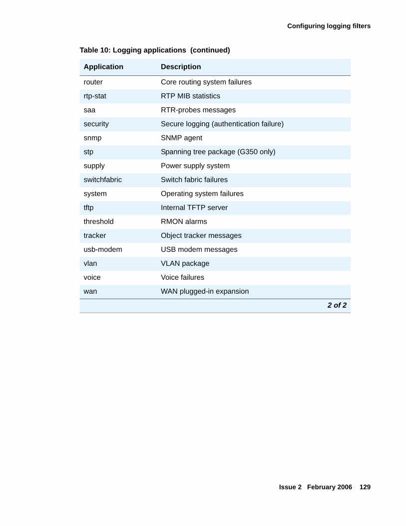
Configuring logging filters
Issue 2 February 2006 129
router Core routing system failures
rtp-stat RTP MIB statistics
saa RTR-probes messages
security Secure logging (authentication failure)
snmp SNMP agent
stp Spanning tree package (G350 only)
supply Power supply system
switchfabric Switch fabric failures
system Operating system failures
tftp Internal TFTP server
threshold RMON alarms
tracker Object tracker messages
usb-modem USB modem messages
vlan VLAN package
voice Voice failures
wan WAN plugged-in expansion
Table 10: Logging applications (continued)
Application Description
2 of 2
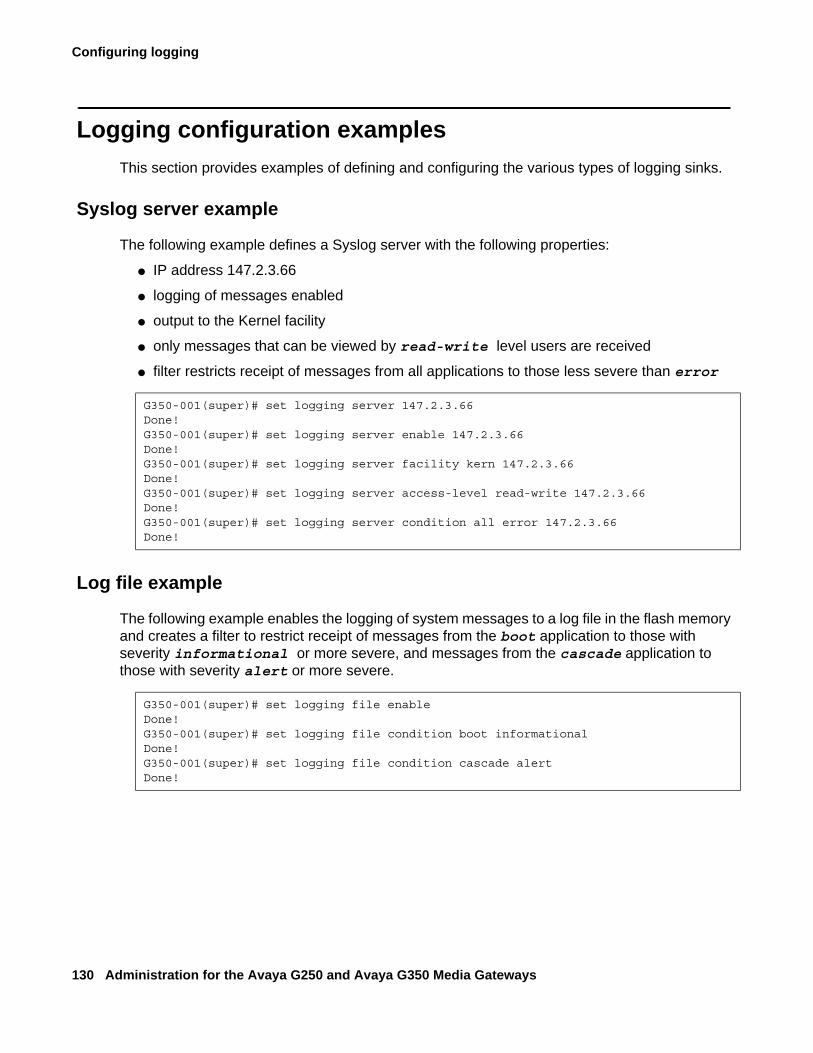
Configuring logging
130 Administration for the Avaya G250 and Avaya G350 Media Gateways
Logging configuration examplesThis section provides examples of defining and configuring the various types of logging sinks.
Syslog server example
The following example defines a Syslog server with the following properties:
● IP address 147.2.3.66
● logging of messages enabled
● output to the Kernel facility
● only messages that can be viewed by read-write level users are received
● filter restricts receipt of messages from all applications to those less severe than error
Log file example
The following example enables the logging of system messages to a log file in the flash memory and creates a filter to restrict receipt of messages from the boot application to those with severity informational or more severe, and messages from the cascade application to those with severity alert or more severe.
G350-001(super)# set logging server 147.2.3.66Done!G350-001(super)# set logging server enable 147.2.3.66Done!G350-001(super)# set logging server facility kern 147.2.3.66Done!G350-001(super)# set logging server access-level read-write 147.2.3.66Done!G350-001(super)# set logging server condition all error 147.2.3.66Done!
G350-001(super)# set logging file enableDone!G350-001(super)# set logging file condition boot informationalDone!G350-001(super)# set logging file condition cascade alertDone!
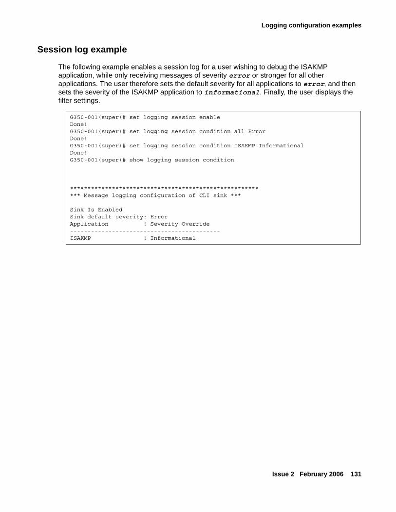
Logging configuration examples
Issue 2 February 2006 131
Session log example
The following example enables a session log for a user wishing to debug the ISAKMP application, while only receiving messages of severity error or stronger for all other applications. The user therefore sets the default severity for all applications to error, and then sets the severity of the ISAKMP application to informational. Finally, the user displays the filter settings.
G350-001(super)# set logging session enableDone!G350-001(super)# set logging session condition all ErrorDone!G350-001(super)# set logging session condition ISAKMP InformationalDone!G350-001(super)# show logging session condition
********************************************************* Message logging configuration of CLI sink ***
Sink Is EnabledSink default severity: ErrorApplication ! Severity Override-------------------------------------------ISAKMP ! Informational

Configuring logging
132 Administration for the Avaya G250 and Avaya G350 Media Gateways
Issue 2 February 2006 133
Chapter 8: Configuring VoIP QoS
This chapter provides information about configuring VoIP on the G250/G350 and contains the following sections:
● VoIP overview — an overview of G250/G350 VoIP configuration
● Configuring RTP and RTCP — instructions on how to configure RTP and RTCP protocols on the G250/G350
● Configuring header compression — instructions on how to configure RTP and TCP header compression
● Configuring QoS parameters — instructions on how to configure MGP QoS parameters on the G250/G350
● Configuring RTCP QoS parameters — instructions on how to configure RTP QoS parameters on the G250/G350
● Configuring RSVP parameters — instructions on how to configure RSVP protocol on the G250/G350
● Configuring Weighted Fair VoIP Queuing (WFVQ) — instructions on how to configure VoIP queueing.
VoIP overviewThe Avaya G250/G350 Media Gateway provides voice services over IP data networks using VoIP. VoIP is a group of protocols for transmitting and receiving various types of voice data over an IP network. VoIP includes protocols for transmitting and receiving the following types of information:
● Digitally encoded voice data
● Call signalling information
● Call routing information
● QoS information
VoIP uses the RTP and RTCP protocols to transmit and receive digitally encoded voice data. For more information about configuring RTP and RTCP on the Avaya G250/G350 Media Gateway, see Configuring RTP and RTCP on page 134.
You can use many types of telephones and trunks that do not directly support VoIP. The Avaya G250/G350 Media Gateway translates voice and signalling data between VoIP and the system used by the telephones and trunks.
Configuring VoIP QoS
134 Administration for the Avaya G250 and Avaya G350 Media Gateways
Configuring RTP and RTCPVoIP uses the RTP and RTCP protocols to transmit and receive digitally encoded voice data. RTP and RTCP are the basis of common VoIP traffic. RTP and RTCP run over UDP and incur a 12-byte header on top of other (IP, UDP) headers. Running on PPP or frame relay, these protocols can be compressed.
Configuring header compressionThis section provides information about configuring header compression in the G250/G350, and contains the following topics:
● Header compression overview
● Configuring IPHC-type header compression
● Configuring VJ-type header compression
● Displaying and clearing header compression statistics
Header compression overviewHeader compression reduces the size of packet headers, thus reducing the amount of bandwidth needed for data. The header compression method is based on the fact that most of the header fields remain constant or change in predictable ways throughout the session. Thus, instead of constantly retransmitting the header, each side keeps a context table of the sessions (the normal headers), and while sending and receiving packets it replaces the full-length headers with 1 or 2 bytes CID (context-id) plus unpredictable deltas from the last packet.
The G250/G350 offers both RTP header compression for reducing the amount of bandwidth needed for voice traffic, and TCP and UDP header compression for reducing the amount of bandwidth needed for non-voice traffic.
For header compression purposes, any UDP packet with an even destination port within a user-configurable range of ports, is considered an RTP packet.
The G250/G350 enables decompression whenever compression is enabled. However, when enabling header compression on a Frame Relay interface, you must first make sure that the remote host is also employing header compression. Header compression on a Frame Relay interface does not check what the remote host is employing. Thus, it may compress headers even when the remote host is not configured to decompress headers.
You can configure how often a full header is transmitted, either as a function of time or of transmitted compressed packets.
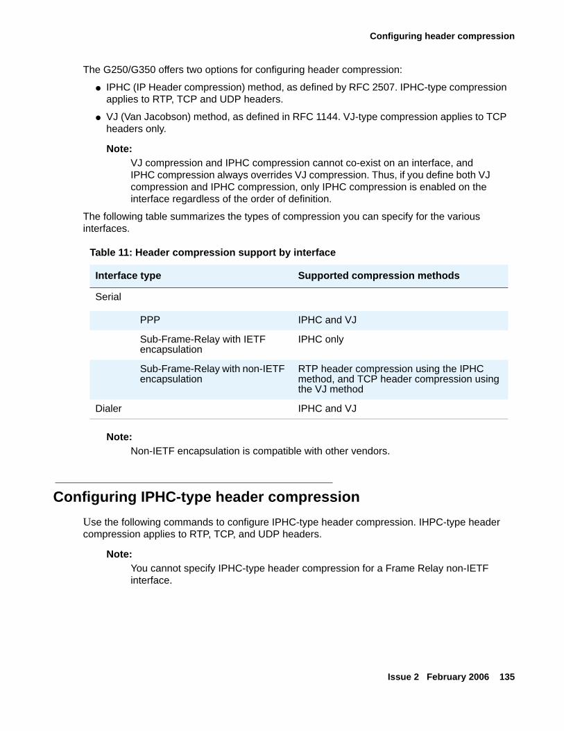
Configuring header compression
Issue 2 February 2006 135
The G250/G350 offers two options for configuring header compression:
● IPHC (IP Header compression) method, as defined by RFC 2507. IPHC-type compression applies to RTP, TCP and UDP headers.
● VJ (Van Jacobson) method, as defined in RFC 1144. VJ-type compression applies to TCP headers only.
Note:Note: VJ compression and IPHC compression cannot co-exist on an interface, and
IPHC compression always overrides VJ compression. Thus, if you define both VJ compression and IPHC compression, only IPHC compression is enabled on the interface regardless of the order of definition.
The following table summarizes the types of compression you can specify for the various interfaces.
Note:Note: Non-IETF encapsulation is compatible with other vendors.
Configuring IPHC-type header compressionUse the following commands to configure IPHC-type header compression. IHPC-type header compression applies to RTP, TCP, and UDP headers.
Note:Note: You cannot specify IPHC-type header compression for a Frame Relay non-IETF
interface.
Table 11: Header compression support by interface
Interface type Supported compression methods
Serial
PPP IPHC and VJ
Sub-Frame-Relay with IETF encapsulation
IPHC only
Sub-Frame-Relay with non-IETF encapsulation
RTP header compression using the IPHC method, and TCP header compression using the VJ method
Dialer IPHC and VJ
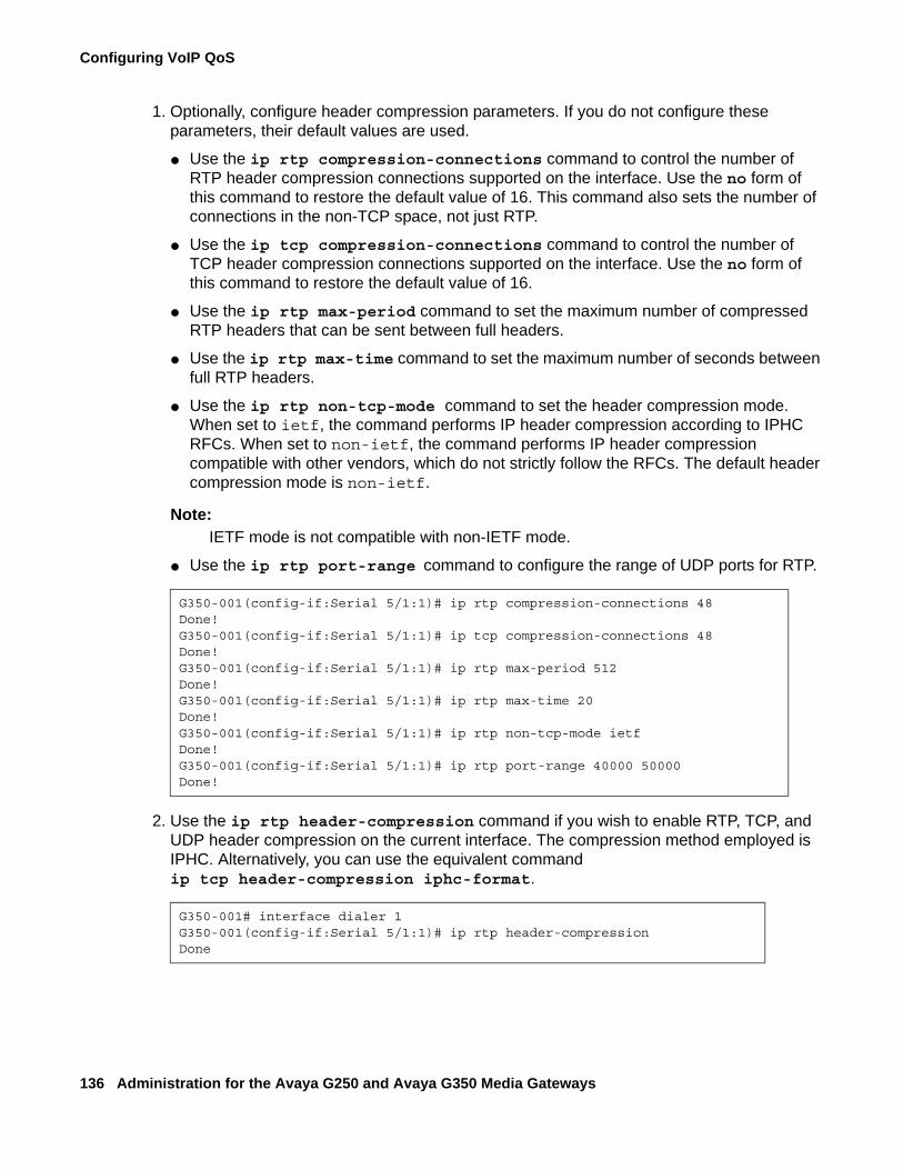
Configuring VoIP QoS
136 Administration for the Avaya G250 and Avaya G350 Media Gateways
1. Optionally, configure header compression parameters. If you do not configure these parameters, their default values are used.
● Use the ip rtp compression-connections command to control the number of RTP header compression connections supported on the interface. Use the no form of this command to restore the default value of 16. This command also sets the number of connections in the non-TCP space, not just RTP.
● Use the ip tcp compression-connections command to control the number of TCP header compression connections supported on the interface. Use the no form of this command to restore the default value of 16.
● Use the ip rtp max-period command to set the maximum number of compressed RTP headers that can be sent between full headers.
● Use the ip rtp max-time command to set the maximum number of seconds between full RTP headers.
● Use the ip rtp non-tcp-mode command to set the header compression mode. When set to ietf, the command performs IP header compression according to IPHC RFCs. When set to non-ietf, the command performs IP header compression compatible with other vendors, which do not strictly follow the RFCs. The default header compression mode is non-ietf.
Note:Note: IETF mode is not compatible with non-IETF mode.
● Use the ip rtp port-range command to configure the range of UDP ports for RTP.
2. Use the ip rtp header-compression command if you wish to enable RTP, TCP, and UDP header compression on the current interface. The compression method employed is IPHC. Alternatively, you can use the equivalent command ip tcp header-compression iphc-format.
G350-001(config-if:Serial 5/1:1)# ip rtp compression-connections 48Done!G350-001(config-if:Serial 5/1:1)# ip tcp compression-connections 48Done!G350-001(config-if:Serial 5/1:1)# ip rtp max-period 512Done!G350-001(config-if:Serial 5/1:1)# ip rtp max-time 20Done!G350-001(config-if:Serial 5/1:1)# ip rtp non-tcp-mode ietfDone!G350-001(config-if:Serial 5/1:1)# ip rtp port-range 40000 50000Done!
G350-001# interface dialer 1G350-001(config-if:Serial 5/1:1)# ip rtp header-compressionDone
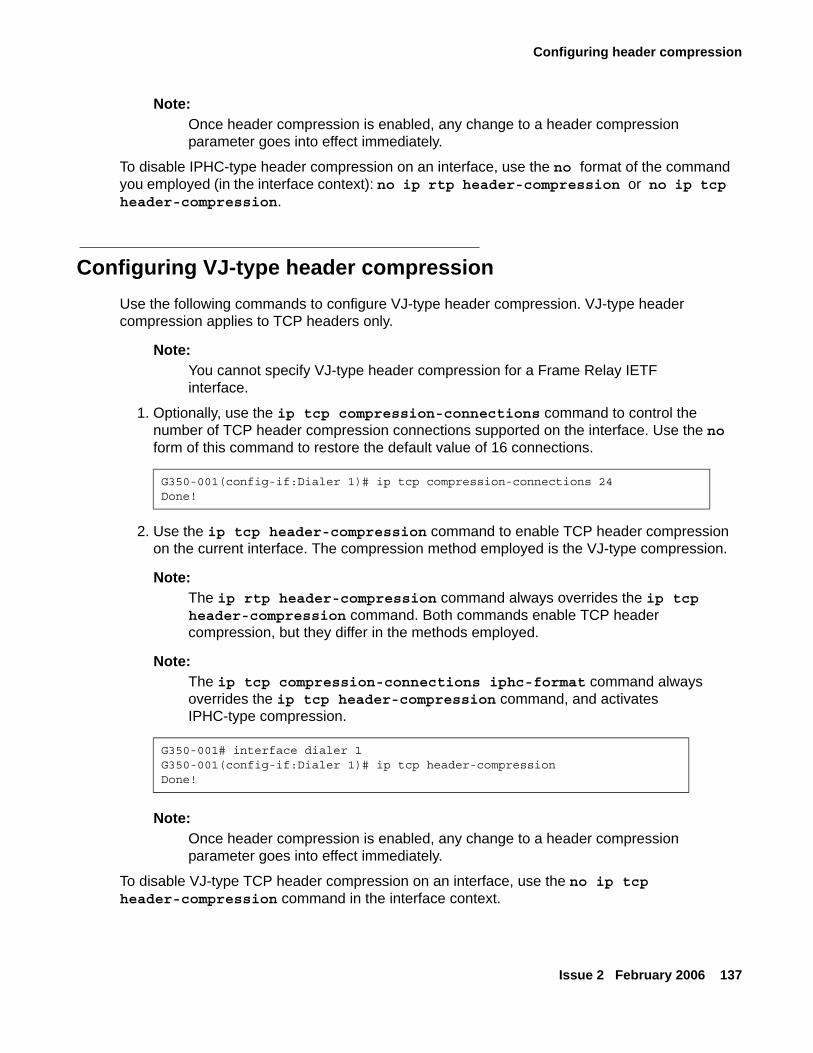
Configuring header compression
Issue 2 February 2006 137
Note:Note: Once header compression is enabled, any change to a header compression
parameter goes into effect immediately.
To disable IPHC-type header compression on an interface, use the no format of the command you employed (in the interface context): no ip rtp header-compression or no ip tcp header-compression.
Configuring VJ-type header compressionUse the following commands to configure VJ-type header compression. VJ-type header compression applies to TCP headers only.
Note:Note: You cannot specify VJ-type header compression for a Frame Relay IETF
interface.
1. Optionally, use the ip tcp compression-connections command to control the number of TCP header compression connections supported on the interface. Use the no form of this command to restore the default value of 16 connections.
2. Use the ip tcp header-compression command to enable TCP header compression on the current interface. The compression method employed is the VJ-type compression.
Note:Note: The ip rtp header-compression command always overrides the ip tcp
header-compression command. Both commands enable TCP header compression, but they differ in the methods employed.
Note:Note: The ip tcp compression-connections iphc-format command always
overrides the ip tcp header-compression command, and activates IPHC-type compression.
Note:Note: Once header compression is enabled, any change to a header compression
parameter goes into effect immediately.
To disable VJ-type TCP header compression on an interface, use the no ip tcp header-compression command in the interface context.
G350-001(config-if:Dialer 1)# ip tcp compression-connections 24Done!
G350-001# interface dialer 1G350-001(config-if:Dialer 1)# ip tcp header-compressionDone!
Configuring VoIP QoS
138 Administration for the Avaya G250 and Avaya G350 Media Gateways
Displaying and clearing header compression statisticsYou can use the following commands to display and clear header compression statistics. For a full description of the commands and their output fields, see Avaya G250 and Avaya G350 CLI Reference, 03-300437.
● Use the show ip rtp header-compression command to display the RTP header compression statistics for a specific interface. If no interface is specified, statistics for all interfaces are displayed.
● Use the show ip tcp header-compression command to display the TCP header compression statistics for a specific interface. If no interface is specified, statistics for all interfaces are displayed. Use this command regardless of which compression method is employed.
● Use the clear ip rtp header-compression command to clear RTP header compression statistics either for all enabled interfaces or for a specific interface. To clear RTP compression statistics for all enabled interfaces, do not enter an interface type and number. Clearing the statistics does not cause renegotiation of parameters.
● Use the clear ip tcp header-compression command to clear TCP header compression statistics either for all enabled interfaces or for a specific interface. To clear TCP compression statistics for all enabled interfaces, do not enter an interface type and number. Clearing the statistics does not cause renegotiation of parameters. Use this command regardless of which compression method is employed.
Configuring QoS parametersThe G250/G350 uses MGCP (H248) protocol for call signalling and call routing information. Use the following commands to configure QoS for signalling and VoIP traffic. For more information about these commands, including parameters and default settings, see Avaya G250 and Avaya G350 CLI Reference, 03-300437.
● Use the set qos control command to define the source for QoS control parameters. The source can be either local where the user configures the values locally on the G250/G350, or remote in which case the values are obtained from the G250/G350’s registered MGC.
● Use the set qos bearer command to provide the means to set up QoS parameters for the VoIP bearer.
Configuring RTCP QoS parameters
Issue 2 February 2006 139
Note:Note: The parameters you define using the set qos bearer command may conflict
with the default QoS list (400). This causes the 801.2p for VoIP packets to differ from settings configured in the QoS list. To avoid this problem, perform the following steps:
1. Create a new QoS list.
2. In the new QoS list, either
● Set the default IP rule composite operation to No Change, OR
● Configure the DSCP map according to the QoS parameters you defined using the set qos bearer command. For instructions on creating a QoS list, see QoS lists on page 465.
● Use the set qos signal command to provide the means to set up QoS parameters for MGCP (H248) communication with the MGC.
● Use the voip-queue-delay command to set the maximum queue delay for which to estimate the high priority queue size necessary to meet the queuing delay for a specific VoIP codec. To determine the queue size you currently have, use the show queueing command.
● Use the show qos command to display the local and downloaded QoS parameters.
Configuring RTCP QoS parametersUse the following commands to configure QoS monitoring for RTCP:
● Use the set qos rtcp command to permit the setup of RTCP parameters. The parameters that can be set are enabling or disabling RTCP reporting capability, setting the IP address of the monitor, setting the reporting period (the default is 5 sec.), and defining the listening port number.
● Use the show qos-rtcp command to display QoS, RSVP, and RTCP parameters.
Configuring VoIP QoS
140 Administration for the Avaya G250 and Avaya G350 Media Gateways
Configuring RSVP parametersVoIP can use the RSVP protocol to reserve network resources for voice data while communicating with other media gateways and other VoIP entities, such as IP phones and Softphones.
● Use the set qos rsvp command to set the current values for the RSVP parameters of the VoIP engines. The parameters that can be set are enabled/disabled, refresh rate (seconds), failure retry (y or n), and service profile (Guaranteed or Controlled).
● Use the show qos-rtcp command to display QoS, RSVP, and RTCP parameters.
Configuring Weighted Fair VoIP Queuing (WFVQ)Weighted Fair VoIP Queuing (WFVQ) combines weighted fair queuing (WFQ) for data streams and priority VoIP queuing to provide the real-time response time that is required for VoIP.
WFQ is applied to data streams to provide fair bandwidth distribution among different data streams, with faster response times for shorter packets that are typical for interactive applications such as telnet. Priority VoIP queuing is applied to VoIP bearer and signaling traffic.
WFVQ is the default queuing mode for all Serial interfaces for which frame-relay traffic-shaping is not enabled, and all Fast Ethernet interfaces for which traffic-shaping is enabled. It is also the only queueing mode available on a per-PVC basis for serial interfaces when frame relay traffic shaping is enabled. To disable WFVQ on an interface, you must enable another queuing mode, using either the voip-queue or the priority-queue command in interface context. To re-enable WFVQ on an interface, use the fair-voip-queue command in interface context. WFVQ is the recommended queuing mode for interfaces.
Note:Note: There is no no form of the fair-voip-queue command. If you enter the
command no fair-voip-queue, it will actually enable WFVQ if WFVQ is not already enabled.
Use the following commands to set the WFVQ queuing parameters.
● Use the voip-queue-delay command to set the maximum query delay. To determine the queue size you currently have, use the show queueing command.
● Use the fair-queue-limit command to specify the maximum number of packets that can be queued in the weighted fair queue. The upper and lower limits of this command depend on the amount of bandwidth configured for the interface.
Note:Note: This command should generally be used only for troubleshooting.
Issue 2 February 2006 141
Chapter 9: Configuring the G250 and G350 for modem use
You can connect either a USB or a serial modem to the Avaya G250/G350 Media Gateway. A USB modem must be connected to the USB port on the G250 or G350 chassis. A serial modem must be connected to the console port (CONSOLE) on the G250 or G350 chassis.
Both the USB port and the console port require configuration for modem use. You can configure the ports for modem use via the Avaya IW or the GIW. For details on using a modem with the G250 or G350, see Installing and Upgrading the Avaya G250 Media Gateway, 03-300434 or Installing and Upgrading the Avaya G350 Media Gateway, 03-300394.
This chapter explains how to use the CLI to configure the console and USB ports for modem use.
Configuring the USB port for modem useBy default, the USB port is not enabled. To enable the USB port, you must enable the USB interface. Use the interface usb-modem command to enable the USB interface. Use the no form of this command to disable the USB interface. The no form of the interface usb-modem command also resets the interface to its default parameter values. These values are:
● Interface status — down
● PPP timeout absolute — 0
To set the USB port’s parameters, use the following commands in USB interface context:
● Use the async reset-modem command to reset the connected modem. You can use this command from within an active PPP session over the USB modem..
● Use the ip address command to assign an IP address to the USB port. This is the IP address to which a remote user can connect using telnet. For example, to assign the IP address 192.168.22.33 to the USB port, use the following command:
There is no default IP address for the USB port.
G350-001(if:USB)# ip address 192.168.22.33 255.255.255.0
Configuring the G250 and G350 for modem use
142 Administration for the Avaya G250 and Avaya G350 Media Gateways
● Use the ppp authentication command to configure the authentication method used when starting a client session on the PPP server. Use this command with one of the following parameters:
- pap — Password Authentication Protocol. An unencrypted password is sent for authentication.
- chap — Challenge Handshake Authentication Protocol. An encrypted password is sent for authentication. To configure this password, use the ppp chap-secret command.
Note:Note: If the G250/G350 firmware is replaced by an earlier firmware version, the ppp
chap-secret is erased, and must be re-configured.
- ras — reserved for future use
- none — no password is sent
Note:Note: The ppp authentication command changes the PPP authentication
parameters of the console port as well as the USB port, even if you use the command in USB interface context.
● Use the shutdown command to disconnect an active PPP session and shut down the modem.
● Use the timeout absolute command to set the number of minutes until the system automatically disconnects an idle PPP incoming session. By default, there is no timeout.
● Use the ip peer address command to change the IP address offered to a requesting calling host during PPP/IPCP connection establishment. By default, the interface offers its own IP address plus one.
● Use the show interface usb-modem command to display the USB interface parameters, the current status of the USB port, and the identity of any USB modem connected to the USB port.
Configuring the console port for modem use
Issue 2 February 2006 143
Configuring the console port for modem useThe console port is labeled Console. The console port is an RJ-45 socket that functions as a serial port. You can connect a console device or serial modem to the console port to access the CLI. For more information, see Accessing the CLI on page 31.
You can set the console port so that it automatically detects whether a console device or a modem is connected to it. Use the async mode interactive command to set the console port to use modem mode every time an Avaya proprietary modem cable is plugged into the console port. If you do not want the console port to automatically detect when a modem is connected to it, use the async mode terminal command to disable interactive mode.
Note:Note: By default, async mode is set to terminal.
Use the following commands to configure the console port for use with a modem:
● Use the interface console command to enter the console interface configuration mode. Use the no form of this command to set the console parameters to their default values.
● Use the async reset-modem command to reset the connected modem.
● Use the speed command to set the PPP baud rate to be used by the console port when connected to a modem (in bits per second). Options are 9600, 19200, 38400, 57600, and 115200. The default baud rate is 38400.
● Use the async modem-type command to configure the console port for the modem type you want to use. By default, the console port is set to work with MultiTech ZBA modems. Set this command to USR-Sportster to use a USR-Sportster modem or to null to use any other modem type.
● Use the ip address command to assign an IP address to the console port. This is the IP address to which a remote user can connect using telnet. For example, to assign the IP address 192.168.22.33 to the console port, use the following command:
● There is no default IP address for the console port.● Use the ppp authentication command to decide the authentication method used
when starting a client session on the PPP server. Use this command with one of the following parameters:- pap — Password Authentication Protocol. An unencrypted password is sent for
authentication.- chap — Challenge Handshake Authentication Protocol. An encrypted password is sent
for authentication. To configure this password, use the ppp chap-secret command.
G350-001(if:Console)# ip address 192.168.22.33 255.255.255.0
Configuring the G250 and G350 for modem use
144 Administration for the Avaya G250 and Avaya G350 Media Gateways
Note:Note: If the G250/G350 firmware is replaced by an earlier firmware version, the ppp
chap-secret is erased, and must be re-configured.
- ras — reserved for future use- none — no password is sent
Note:Note: This command changes the PPP authentication parameters of the USB port as
well as the console port, even if you use the command in console interface context.
● Use the shutdown command to disconnect an active PPP session and shut down the modem.
● Use the timeout absolute command to set the number of minutes until the system automatically disconnects an idle PPP incoming session. By default, there is no timeout.
● Use the load-interval command to set the load calculation interval for the interface.
When you use a console device to access the CLI through the console port, you must configure the serial connection on the console device to match the configuration of the console port. The console port uses the following settings:
● baud — 9600
● data bits — 8
● parity — none
● stop bits — 1
● flow control — hardware
Issue 2 February 2006 145
Chapter 10: Configuring WAN interfaces
This chapter provides information about configuring WAN features on the Avaya G250/G350 Media Gateway and contains the following sections:
● WAN overview — a description of the WAN features supported on the G250/G350
● Serial interface overview — an overview of serial interfaces
● Initial WAN configuration — instructions on how to configure a WAN line on the G250/G350
● Backup interfaces — a description of backup interfaces and how they work on the G250/G350
● Modem dial backup — a description of modem dial backup using the Dialer interface and how to configure it on the G250/G350
● ICMP keepalive — a description of the ICMP keepalive feature for sending ping packets through an interface at defined intervals to determine if the interface is up or down
● Dynamic CAC — a description of dynamic CAC and how to configure it on a WAN interface
● Object tracking — a description of object tracking and how to configure it on a WAN interface
● Frame relay encapsulation features — a description of the frame relay encapsulation features supported on the G250/G350
● Priority DLCI — a description of class-based traffic assignment (priority DLCI) and how to configure priority DLCI on a WAN interface
● WAN configuration example — an example of a WAN configuration on the G250/G350
WAN overviewYou can use an MM340 E1/T1 media module or an MM342 USP media module as an endpoint for a WAN line on both the G250 and the G350. You can also use the Fast Ethernet port on the G250/G350 chassis as the endpoint for a WAN line by configuring the Fast Ethernet interface for PPP over Ethernet (PPPoE). The G250/G350 serves as a router, as well as the endpoint, for the WAN line. For more information about routing, see Configuring the router on page 333.
The G250/G350 supports the following WAN features:
● PPP over channeled and fractional E1/T1 — the G250/G350 has the ability to map several PPP sessions to a single E1/T1 interface
● PPP over USP
Configuring WAN interfaces
146 Administration for the Avaya G250 and Avaya G350 Media Gateways
● PPPoE
● Unframed E1 for enabling full 2.048 Mbps bandwidth usage
● Point-to-Point frame relay encapsulation over channelized, fractional, or unframed E1/T1 ports or over a USP interface
● Frame relay — the G250/G350 supports the following LMI types:
- ANSI (Annex D)
- ITU-T:Q-933 (Annex A0)
- LMI-Rev1
- No LMI
● Backup functionality supported between any type of Serial Layer 2 interface. For more information, see Backup interfaces on page 162.
● Dynamic CAC for Fast Ethernet, Serial, and GRE tunnel interfaces. For more information, see Dynamic CAC on page 186.
● Quality of Service (QoS) — the G250/G350 uses Weighted Fair VoIP Queuing (WFVQ) as the default queuing mode for WAN interfaces. WFVQ combines weighted fair queuing (WFQ) for data streams and priority VoIP queuing to provide the real-time response time that is required for VoIP. The G250/G350 also supports the VoIP Queue and Priority Queue legacy queuing methods. For more information, see Configuring Weighted Fair VoIP Queuing (WFVQ) on page 140.
● Policy — each interface on the G250/G350 can have four active policy lists:
- Ingress Access Control List
- Ingress QoS List
- Egress Access Control List
- Egress QoS List
Access control lists define which packets should be forwarded or denied access to the network. QoS lists change the DSCP and 802.1p priority of routed packets according to the packet characteristics. For more information, see Configuring policy on page 463.
Each interface on the G250/G350 can also have an active policy-based routing list. For more information, see Chapter 21: Configuring policy-based routing on page 487.
● Header Compression — use of header compression reduces the size of packet headers, thus reducing the amount of bandwidth needed for data. RTP header compression enhances the efficiency of voice transmission over the network by compressing the headers of Real Time Protocol (RTP) packets, thereby minimizing the overhead and delays involved in RTP implementation. TCP header compression reduces the amount of bandwidth needed for non-voice traffic. For more information, see Configuring header compression on page 134.
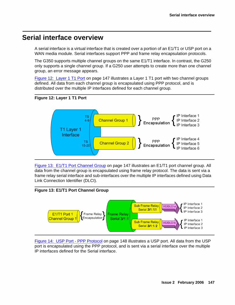
Serial interface overview
Issue 2 February 2006 147
Serial interface overviewA serial interface is a virtual interface that is created over a portion of an E1/T1 or USP port on a WAN media module. Serial interfaces support PPP and frame relay encapsulation protocols.
The G350 supports multiple channel groups on the same E1/T1 interface. In contrast, the G250 only supports a single channel group. If a G250 user attempts to create more than one channel group, an error message appears.
Figure 12: Layer 1 T1 Port on page 147 illustrates a Layer 1 T1 port with two channel groups defined. All data from each channel group is encapsulated using PPP protocol, and is distributed over the multiple IP interfaces defined for each channel group.
Figure 12: Layer 1 T1 Port
Figure 13: E1/T1 Port Channel Group on page 147 illustrates an E1/T1 port channel group. All data from the channel group is encapsulated using frame relay protocol. The data is sent via a frame relay serial interface and sub-interfaces over the multiple IP interfaces defined using Data Link Connection Identifier (DLCI).
Figure 13: E1/T1 Port Channel Group
Figure 14: USP Port - PPP Protocol on page 148 illustrates a USP port. All data from the USP port is encapsulated using the PPP protocol, and is sent via a serial interface over the multiple IP interfaces defined for the Serial interface.
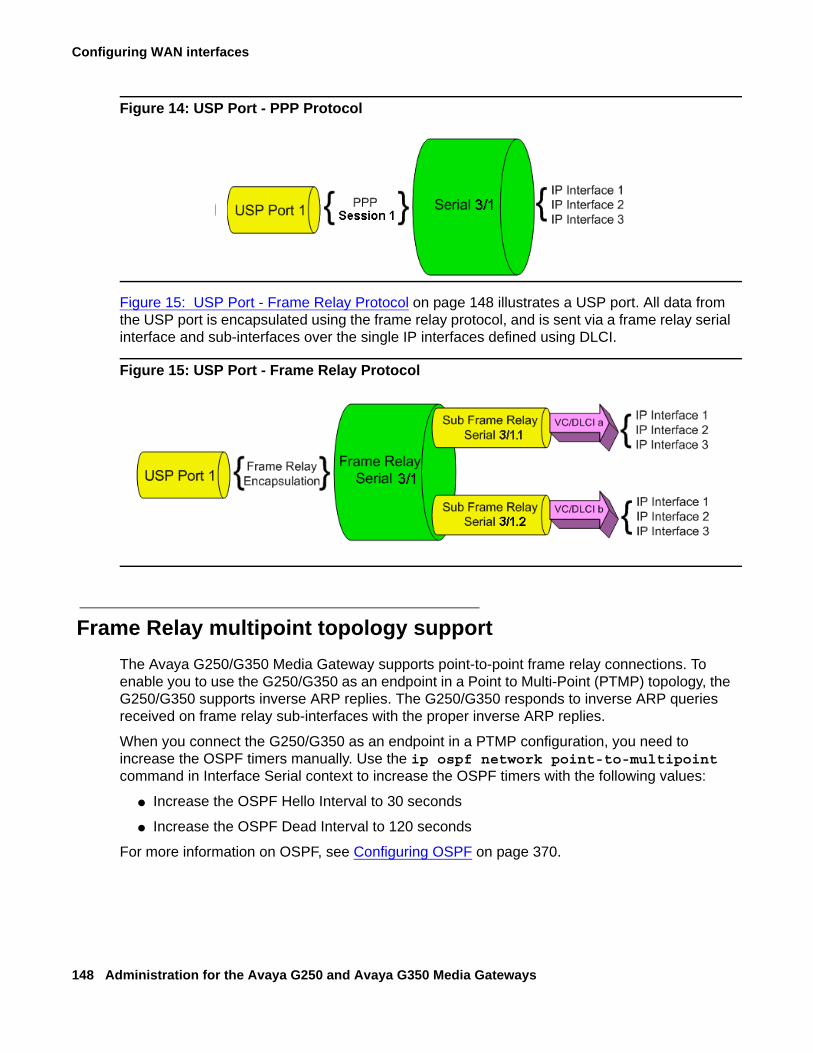
Configuring WAN interfaces
148 Administration for the Avaya G250 and Avaya G350 Media Gateways
Figure 14: USP Port - PPP Protocol
Figure 15: USP Port - Frame Relay Protocol on page 148 illustrates a USP port. All data from the USP port is encapsulated using the frame relay protocol, and is sent via a frame relay serial interface and sub-interfaces over the single IP interfaces defined using DLCI.
Figure 15: USP Port - Frame Relay Protocol
Frame Relay multipoint topology supportThe Avaya G250/G350 Media Gateway supports point-to-point frame relay connections. To enable you to use the G250/G350 as an endpoint in a Point to Multi-Point (PTMP) topology, the G250/G350 supports inverse ARP replies. The G250/G350 responds to inverse ARP queries received on frame relay sub-interfaces with the proper inverse ARP replies.
When you connect the G250/G350 as an endpoint in a PTMP configuration, you need to increase the OSPF timers manually. Use the ip ospf network point-to-multipoint command in Interface Serial context to increase the OSPF timers with the following values:
● Increase the OSPF Hello Interval to 30 seconds
● Increase the OSPF Dead Interval to 120 seconds
For more information on OSPF, see Configuring OSPF on page 370.
Initial WAN configuration
Issue 2 February 2006 149
Initial WAN configurationTo configure the Avaya G250/G350 Media Gateway to support a WAN:
1. Add one of the following WAN media modules:
- Avaya MM340 E1/T1 media module
- Avaya MM342 USP media module
Note:Note: You can also use the Fast Ethernet port on the G250/G350 chassis as the
endpoint for a WAN line by configuring this interface for PPPoE. See Configuring PPPoE on page 155.
2. Connect the WAN line to the media module. For more information, see Installing and Upgrading the Avaya G250 Media Gateway, 03-300434 or Installing and Upgrading the Avaya G350 Media Gateway, 03-300394.
3. Configure the WAN interface on the WAN media module:
- For the MM340, see Configuring the Avaya MM340 E1/T1 WAN media module on page 149.
- For the MM342, see Configuring the Avaya MM342 USP WAN media module on page 153.
4. By default, a G250/G350 WAN interface uses Point-to-Point Protocol (PPP). For instructions on changing the default PPP parameters, see Configuring PPP on page 155.
5. If you want frame relay encapsulation on the WAN, configure frame relay. See Configuring frame relay on page 159.
6. Test the WAN configuration. See Verifying the WAN configuration and testing connectivity on page 161.
7. Use the copy running-config startup-config command to save the configuration.
Configuring the Avaya MM340 E1/T1 WAN media moduleFor a list of G250/G350 default settings, see E1/T1 default settings on page 152. To display the current settings, use the show controllers command.
To configure an E1 or T1 port:
1. Use the show-ds command to check if the G250/G350 is configured for E1 or T1 operation.
2. Use the ds-mode command to set the mode of the G250/G350 to E1 or T1. Changing the line type requires resetting the module. The default value is T1.
Configuring WAN interfaces
150 Administration for the Avaya G250 and Avaya G350 Media Gateways
3. Use the controller ds-mode slot/port command to enter controller context for the port to be configured. The prompt changes to:
where s is the slot number of the media module, and p is the port number.
4. Use the following commands to change the clock source, frame type, linecode, or cable length parameters from the default settings:
- For T1 mode:
clock source line|internal (default is line)
framing sf|esf (default is sf)
linecode ami|b8zs (default is ami)
cablelength long|short (default is long, gain26, 0db)
Note:Note: Use the cablelength command to configure the cable’s transmit and receive
levels. If the cable is longer than 655 feet, use the command cablelength long gain26|gain36 -15db|-22.5db|-7.5db|0db (default gain26, 0db). If the cable is 655 feet or less, use the command cablelength short 133ft|266ft|399ft|533ft|655ft (default 133ft). When using the cablelength short form of the command, the transmit attenuation is configured using the loop length.
- For E1 mode:
clock source line|internal (default is line)
framing crc4|no-crc4|unframed (default is crc4)
linecode ami|hdb3 (default is hdb3)
5. Use the channel-group command to specify the channel group and time slots to be mapped, as well as the DS0 speed. For example:
- For T1 mode:
channel-group 1 timeslots 1,3-5,7 speed 64
configures time slots numbered 1, 3-5 and 7 to be mapped in channel-group number 1, and sets the DS0 speed to 64 kbps. The default DS0 speed for T1 mode is 56.
- For E1 mode:
channel-group 1 timeslots 1,3-5,7 speed 64
configures time slots numbered 1, 3-5, and 7 to be mapped in channel-group number 1, and sets the DS0 speed to 64 kbps. The default DS0 speed for E1 mode is 64.
Note:Note: The G250 only supports a single channel group.
G350-001(super-if:Serial s/p)#
Initial WAN configuration
Issue 2 February 2006 151
6. Type exit to return to general context. The prompt returns to:
7. Use the interface Serial command to enter the context of the interface. Specify the slot number of the media module, the port number, the channel group number, and optionally, the IP interface number.
Note:Note: The WAN media module in a G250 must always be in slot number 2. The G250
only supports a single channel group.
If you do not specify an IP interface number for the first serial interface that you define on a channel group, the G250/G350 automatically assigns IP interface number 0. For each additional serial interface that you define on the channel group, use a different IP interface number. For example:
- interface Serial 2/1:1 enters a serial interface on the media module in slot number 2, on port number 1, with channel group number 1.
- interface Serial 5/1:2.3 enters a serial interface on the media module in slot number 5, on port number 1, with channel group number 2, and with IP interface number 3.
Note:Note: If you use the framing unframed command in Step 3 for an E1 port, a channel
group is automatically created on the entire E1 bandwidth. The channel group has the number 0. In Step 6, use the command interface Serial s/p:0 where s is the slot number and p is the port number.
Note:Note: After the serial interface is created, its default encapsulation is PPP.
8. Configure the interface encapsulation:
- By default, the serial interface uses PPP encapsulation. For information on setting PPP parameters, or instructions on returning the interface to the default PPP encapsulation after it has been configured for a different encapsulation, see Configuring PPP on page 155.
- For frame relay encapsulation, see Configuring frame relay on page 159.
9. Use the ip address command to configure the IP address and subnet mask of the interface.
10. Type exit to return to general context. The prompt returns to:
11. If needed, repeat Step 7 through Step 9 to configure additional IP interfaces on the same channel group.
G350-001(super)#
G350-001(super)#
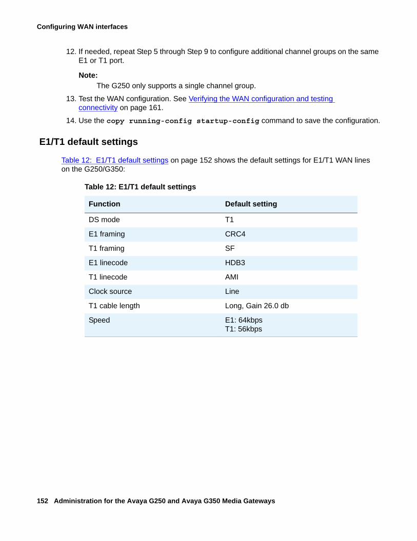
Configuring WAN interfaces
152 Administration for the Avaya G250 and Avaya G350 Media Gateways
12. If needed, repeat Step 5 through Step 9 to configure additional channel groups on the same E1 or T1 port.
Note:Note: The G250 only supports a single channel group.
13. Test the WAN configuration. See Verifying the WAN configuration and testing connectivity on page 161.
14. Use the copy running-config startup-config command to save the configuration.
E1/T1 default settings
Table 12: E1/T1 default settings on page 152 shows the default settings for E1/T1 WAN lines on the G250/G350:
Table 12: E1/T1 default settings
Function Default setting
DS mode T1
E1 framing CRC4
T1 framing SF
E1 linecode HDB3
T1 linecode AMI
Clock source Line
T1 cable length Long, Gain 26.0 db
Speed E1: 64kbpsT1: 56kbps
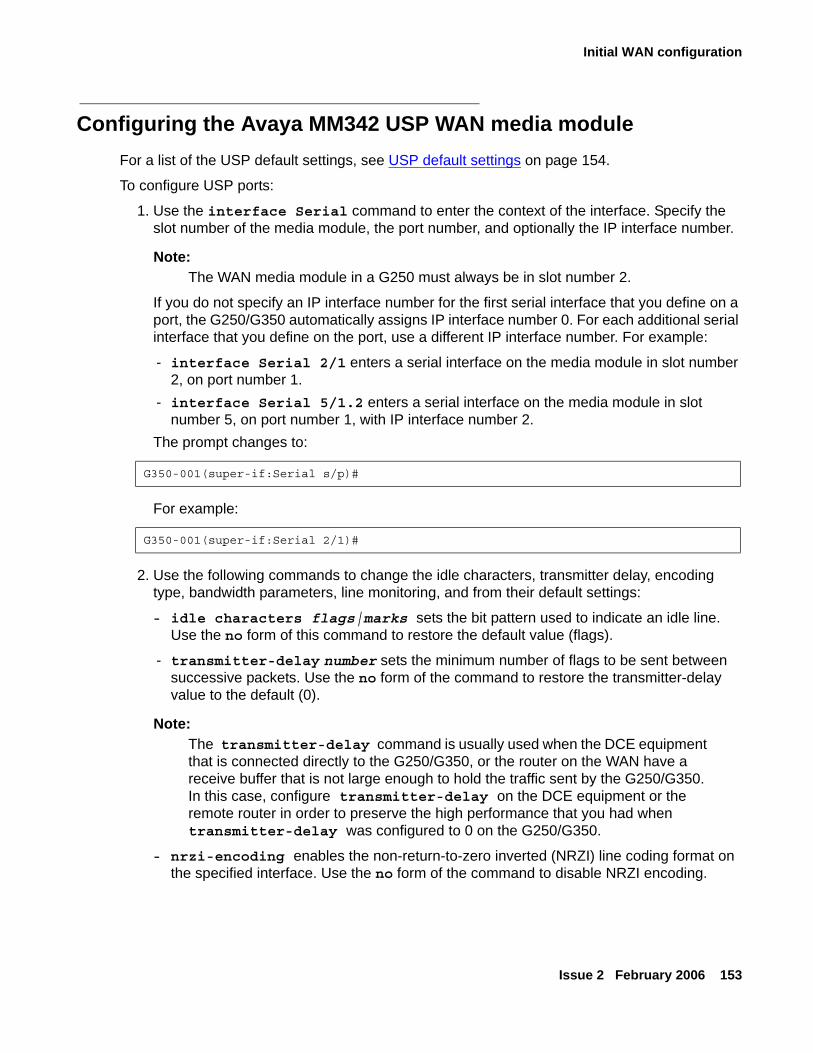
Initial WAN configuration
Issue 2 February 2006 153
Configuring the Avaya MM342 USP WAN media moduleFor a list of the USP default settings, see USP default settings on page 154.
To configure USP ports:
1. Use the interface Serial command to enter the context of the interface. Specify the slot number of the media module, the port number, and optionally the IP interface number.
Note:Note: The WAN media module in a G250 must always be in slot number 2.
If you do not specify an IP interface number for the first serial interface that you define on a port, the G250/G350 automatically assigns IP interface number 0. For each additional serial interface that you define on the port, use a different IP interface number. For example:
- interface Serial 2/1 enters a serial interface on the media module in slot number 2, on port number 1.
- interface Serial 5/1.2 enters a serial interface on the media module in slot number 5, on port number 1, with IP interface number 2.
The prompt changes to:
For example:
2. Use the following commands to change the idle characters, transmitter delay, encoding type, bandwidth parameters, line monitoring, and from their default settings:
- idle characters flags|marks sets the bit pattern used to indicate an idle line. Use the no form of this command to restore the default value (flags).
- transmitter-delay number sets the minimum number of flags to be sent between successive packets. Use the no form of the command to restore the transmitter-delay value to the default (0).
Note:Note: The transmitter-delay command is usually used when the DCE equipment
that is connected directly to the G250/G350, or the router on the WAN have a receive buffer that is not large enough to hold the traffic sent by the G250/G350. In this case, configure transmitter-delay on the DCE equipment or the remote router in order to preserve the high performance that you had when transmitter-delay was configured to 0 on the G250/G350.
- nrzi-encoding enables the non-return-to-zero inverted (NRZI) line coding format on the specified interface. Use the no form of the command to disable NRZI encoding.
G350-001(super-if:Serial s/p)#
G350-001(super-if:Serial 2/1)#
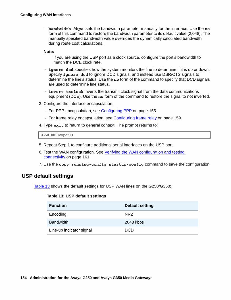
Configuring WAN interfaces
154 Administration for the Avaya G250 and Avaya G350 Media Gateways
- bandwidth kbps sets the bandwidth parameter manually for the interface. Use the no form of this command to restore the bandwidth parameter to its default value (2,048). The manually specified bandwidth value overrides the dynamically calculated bandwidth during route cost calculations.
Note:Note: If you are using the USP port as a clock source, configure the port’s bandwidth to
match the DCE clock rate.
- ignore dcd specifies how the system monitors the line to determine if it is up or down. Specify ignore dcd to ignore DCD signals, and instead use DSR/CTS signals to determine the line’s status. Use the no form of the command to specify that DCD signals are used to determine line status.
- invert txclock inverts the transmit clock signal from the data communications equipment (DCE). Use the no form of the command to restore the signal to not inverted.
3. Configure the interface encapsulation:
- For PPP encapsulation, see Configuring PPP on page 155.
- For frame relay encapsulation, see Configuring frame relay on page 159.
4. Type exit to return to general context. The prompt returns to:
5. Repeat Step 1 to configure additional serial interfaces on the USP port.
6. Test the WAN configuration. See Verifying the WAN configuration and testing connectivity on page 161.
7. Use the copy running-config startup-config command to save the configuration.
USP default settings
Table 13 shows the default settings for USP WAN lines on the G250/G350:
G350-001(super)#
Table 13: USP default settings
Function Default setting
Encoding NRZ
Bandwidth 2048 kbps
Line-up indicator signal DCD
Initial WAN configuration
Issue 2 February 2006 155
Configuring PPPPPP is the default encapsulation on a WAN port. If the encapsulation has been changed to frame relay and you want to restore PPP encapsulation, or to change the PPP parameters:
1. Ensure that you are in the context of a serial interface that is defined on the port. If you are not in the context of a serial interface, use the interface Serial command. To view all serial interfaces that are defined, use the show interfaces Serial command.
2. If the interface is not already configured to use PPP encapsulation, use the encapsulation ppp command to change the encapsulation to PPP.
3. If you want to change the queuing mode of the interface, see Configuring Weighted Fair VoIP Queuing (WFVQ) on page 140 for instructions.
4. Use the following commands to change the interface parameters:
- Use the ip address command to configure the IP address and subnet mask of the interface.
- Use the ppp timeout ncp command to set the maximum time to wait for the network layer to negotiate. If this time is exceeded, the G250/G350 restarts the PPP session.
- Use the ppp timeout retry command to set the maximum time to wait for a response during PPP negotiation.
- Use the keepalive-icmp command to enable keepalive or change the interval to which keepalive is set. When activated, keepalive performs the initial negotiation and sends health checks at defined intervals to the other side of the interface. To deactivate keepalive, use the no form of the command or set the health check interval to 0.
5. Type exit to return to general context. The prompt returns to:
6. Test the WAN configuration. See Verifying the WAN configuration and testing connectivity on page 161.
7. Use the copy running-config startup-config command to save the configuration.
Configuring PPPoEYou can configure the ETH WAN Fast Ethernet port as a WAN port using PPPoE (PPP over Ethernet). PPPoE offers dialup style authentication and accounting and allows subscribers to dynamically select their ISP.
G350-001(super)#
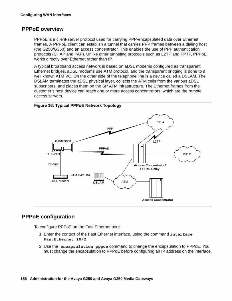
Configuring WAN interfaces
156 Administration for the Avaya G250 and Avaya G350 Media Gateways
PPPoE overview
PPPoE is a client-server protocol used for carrying PPP-encapsulated data over Ethernet frames. A PPPoE client can establish a tunnel that carries PPP frames between a dialing host (the G250/G350) and an access concentrator. This enables the use of PPP authentication protocols (CHAP and PAP). Unlike other tunneling protocols such as L2TP and PPTP, PPPoE works directly over Ethernet rather than IP.
A typical broadband access network is based on aDSL modems configured as transparent Ethernet bridges. aDSL modems use ATM protocol, and the transparent bridging is done to a well known ATM VC. On the other side of the telephone line is a device called a DSLAM. The DSLAM terminates the aDSL physical layer, collects the ATM cells from the various aDSL subscribers, and places them on the SP ATM infrastructure. The Ethernet frames from the customer’s host device can reach one or more access concentrators, which are the remote access servers.
Figure 16: Typical PPPoE Network Topology
PPPoE configuration
To configure PPPoE on the Fast Ethernet port:
1. Enter the context of the Fast Ethernet interface, using the command interface FastEthernet 10/2.
2. Use the encapsulation pppoe command to change the encapsulation to PPPoE. You must change the encapsulation to PPPoE before configuring an IP address on the interface.
ISP A
DSL Modem
ETH-WAN
ATM over DSL
G250/G350
DSLAM ATM
L2TP
PPP
PPPoE
Access Concentrator/PPPoE Relay
Access Concentrator
ISP B
Ethernet
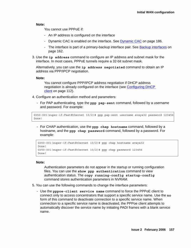
Initial WAN configuration
Issue 2 February 2006 157
Note:Note: You cannot use PPPoE if:
- An IP address is configured on the interface
- Dynamic CAC is enabled on the interface. See Dynamic CAC on page 186.
- The interface is part of a primary-backup interface pair. See Backup interfaces on page 162.
3. Use the ip address command to configure an IP address and subnet mask for the interface. In most cases, PPPoE tunnels require a 32-bit subnet mask.
Alternatively, you can use the ip address negotiated command to obtain an IP address via PPP/IPCP negotiation.
Note:Note: You cannot configure PPP/IPCP address negotiation if DHCP address
negotiation is already configured on the interface (see Configuring DHCP client on page 112).
4. Configure an authentication method and parameters:
- For PAP authenticating, type the ppp pap-sent command, followed by a username and password. For example:
- For CHAP authentication, use the ppp chap hostname command, followed by a hostname, and the ppp chap password command, followed by a password. For example:
Note:Note: Authentication parameters do not appear in the startup or running configuration
files. You can use the show ppp authentication command to view authentication status. The copy running-config startup-config command stores authentication parameters in NVRAM.
5. You can use the following commands to change the interface parameters:
- Use the pppoe-client service name command to force the PPPoE client to connect only to access concentrators that support a specific service name. Use the no form of this command to deactivate connection to a specific service name. When connection to a specific service name is deactivated, the PPPoe client attempts to automatically discover the service name by initiating PADI frames with a blank service name.
G350-001(super-if:FastEthernet 10/2)# ppp pap-sent username avaya32 password 123456Done!
G350-001(super-if:FastEthernet 10/2)# ppp chap hostname avaya32Done!G350-001(super-if:FastEthernet 10/2)# ppp chap password 123456Done!
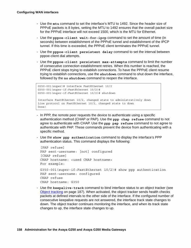
Configuring WAN interfaces
158 Administration for the Avaya G250 and Avaya G350 Media Gateways
- Use the mtu command to set the interface’s MTU to 1492. Since the header size of PPPoE packets is 8 bytes, setting the MTU to 1492 ensures that the overall packet size for the PPPoE interface will not exceed 1500, which is the MTU for Ethernet.
- Use the pppoe-client wait-for-ipcp command to set the amount of time (in seconds) between establishment of the PPPoE tunnel and establishment of the IPCP tunnel. If this time is exceeded, the PPPoE client terminates the PPPoE tunnel.
- Use the pppoe-client persistent delay command to set the interval between pppoe-client dial attempts.
- Use the pppoe-client persistent max-attempts command to limit the number of consecutive connection establishment retries. When this number is reached, the PPPoE client stops trying to establish connections. To have the PPPoE client resume trying to establish connections, use the shutdown command to shut down the interface, followed by the no shutdown command to reopen the interface.
- In PPP, the remote peer requests the device to authenticate using a specific authentication method (CHAP or PAP). Use the ppp chap refuse command to not agree to authenticate with CHAP. Use the ppp pap refuse command to not agree to authenticate with PAP. These commands prevent the device from authenticating with a specific method.
- Use the show ppp authentication command to display the interface’s PPP authentication status. This command displays the following:
[PAP refuse]PAP sent-username: [not] configured[CHAP refuse]CHAP hostname: <used CHAP hostname>For example:
G350-001(super-if:FastEthernet 10/2)# show ppp authenticationPAP sent-username: configuredCHAP refuseCHAP hostname: G350
- Use the keepalive-track command to bind interface status to an object tracker (see Object tracking on page 187). When activated, the object tracker sends health checks packets at defined intervals to the other side of the interface. If the configured number of consecutive keepalive requests are not answered, the interface track state changes to down. The object tracker continues monitoring the interface, and when its track state changes to up, the interface state changes to up.
G350-001(super)# interface FastEthernet 10/2G350-001(super-if:FastEthernet 10/2)#G350-001(super-if:FastEthernet 10/2)# shutdown
Interface FastEthernet 10/2, changed state to administratively downLine protocol on FastEthernet 10/2, changed state to downDone!
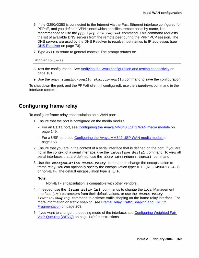
Initial WAN configuration
Issue 2 February 2006 159
6. If the G250/G350 is connected to the Internet via the Fast Ethernet interface configured for PPPoE, and you define a VPN tunnel which specifies remote hosts by name, it is recommended to use the ppp ipcp dns request command. This command requests the list of available DNS servers from the remote peer during the PPP/IPCP session. The DNS servers are used by the DNS Resolver to resolve host names to IP addresses (see DNS Resolver on page 73).
7. Type exit to return to general context. The prompt returns to:
8. Test the configuration. See Verifying the WAN configuration and testing connectivity on page 161.
9. Use the copy running-config startup-config command to save the configuration.
To shut down the port, and the PPPoE client (if configured), use the shutdown command in the interface context.
Configuring frame relayTo configure frame relay encapsulation on a WAN port:
1. Ensure that the port is configured on the media module:
- For an E1/T1 port, see Configuring the Avaya MM340 E1/T1 WAN media module on page 149.
- For a USP port, see Configuring the Avaya MM342 USP WAN media module on page 153.
2. Ensure that you are in the context of a serial interface that is defined on the port. If you are not in the context of a serial interface, use the interface Serial command. To view all serial interfaces that are defined, use the show interfaces Serial command.
3. Use the encapsulation frame-relay command to change the encapsulation to frame relay. You can optionally specify the encapsulation type: IETF (RFC1490/RFC2427) or non-IETF. The default encapsulation type is IETF.
Note:Note: Non-IETF encapsulation is compatible with other vendors.
4. If needed, use the frame-relay lmi commands to change the Local Management Interface (LMI) parameters from their default values, or use the frame-relay traffic-shaping command to activate traffic shaping on the frame relay interface. For more information on traffic shaping, see Frame Relay Traffic Shaping and FRF.12 Fragmentation on page 203.
5. If you want to change the queuing mode of the interface, see Configuring Weighted Fair VoIP Queuing (WFVQ) on page 140 for instructions.
G350-001(super)#
Configuring WAN interfaces
160 Administration for the Avaya G250 and Avaya G350 Media Gateways
6. Type exit to return to general context. The prompt returns to:
7. Use the interface Serial if.fr-sub-if point-to-point command to create a frame relay sub-interface and enter the context of the interface. For example:
- interface Serial 2/1:2.1 point-to-pointcreates frame relay sub-interface number 1 on the E1/T1 media module in slot number 2, on port number 1, with channel group number 2
- interface Serial 5/1:2.3.2 point-to-pointcreates frame relay sub-interface number 3 on the E1/T1 media module in slot number 5, on port number 1, with channel group number 2, and with IP interface number 2
- interface Serial 2/1.2 point-to-pointcreates frame relay sub-interface number 2 on the USP media module in slot number 2, on port number 1
- interface Serial 5/1.2.1 point-to-pointcreates frame relay sub-interface number 2 on the USP media module in slot number 5, on port number 1, with IP interface number 1
Note:Note: The WAN media module in a G250 must always be in slot number 2. The G250
only supports a single channel group.
Note:Note: Currently only point-to-point frame relay sub-interfaces are supported.
8. Use the frame-relay interface-dlci DLCI-number command to configure a Data Link Connection Identifier (DLCI) for the frame relay sub-interface. You can optionally specify the encapsulation type: IETF (RFC1490/RFC2427) or non-IETF. The default encapsulation type is IETF.
Note:Note: Non-IETF encapsulation is compatible with other vendors.
9. If required, use the frame-relay priority-dlci-group command to configure a Priority DLCI group. The arguments for this command are the DLCIs you want to assign to high, medium, normal, and low priority traffic, respectively. For example, the command frame-relay priority-dlci-group 17 18 19 assigns DLCI 17 to high priority traffic, DLCI 18 to medium priority traffic, and DLCI 19 to normal and low priority traffic. For more information, see Frame Relay Traffic Shaping and FRF.12 Fragmentation on page 203.
10. Use the ip address command to configure an IP address and subnet mask for the frame relay sub-interface.
G350-001(super)#
Initial WAN configuration
Issue 2 February 2006 161
11. Type exit to return to general context. The prompt returns to:
12. If needed, repeat Step 6 through Step 10 to configure additional frame relay sub-interfaces on the same serial interface.
13. If needed, repeat Step 2 through Step 11 to configure frame relay encapsulation for other serial interfaces on the same WAN port.
14. Test the WAN configuration. See Verifying the WAN configuration and testing connectivity on page 161.
15. Use the copy running-config startup-config command to save the configuration.
Verifying the WAN configuration and testing connectivityAfter configuring the new interface, you can perform the following tests to verify that the new interface is operating correctly.
● For E1/T1 interfaces, use the show controllers command to view the status of the interface’s controller. Make sure the controller is up, and that all error counters do not increase.
● For all serial interfaces (E1/T1 and USB), use the show interfaces Serial command to verify that the interface and line protocol are both up:
Serial x/y:z is up, line protocol is up
● For USB interfaces only, use the show interfaces Serial command to verify that all line signals are up:
DCD = up DSR = up DTR = up RTS = up CTS - up
● Use the show frame-relay pvc command to view basic information about frame relay configuration. For more information about frame relay configuration, use the following commands:
- show frame-relay fragment to display frame relay fragmentation statistics and configuration on all PVCs associated with the interface.
- show frame-relay lmi to display LMI statistics for the interface.
- show frame-relay map to display a summary table of frame relay sub-interfaces and DLCIs associated with the sub-interfaces.
- show frame-relay traffic to display frame relay protocol statistics, including ARP requests and replies sent and received over the interface.
- show map-class frame-relay to display the map-class Frame Relay table.
G350-001(super)#
Configuring WAN interfaces
162 Administration for the Avaya G250 and Avaya G350 Media Gateways
● Use the show traffic-shape command to view traffic shaping and frame relay traffic shaping configuration parameters for all interfaces.
● Use the show ip interface command to display information about IP interfaces. To display information about a specific interface, include the name of the interface as an argument. To display information about the interface of a specific IP address, include the IP address as an argument.
● Use the show running-config command to display the configuration running on the device.
● Use the show startup-config command to display the configuration loaded at startup.
● Use the ping command to send ICMP echo request packets from the G250/G350 to the interface serial peer IP address and verify that it responds.
● Use the ping command to send ICMP echo request packets to another node on the network. Each node is periodically pinged and checked if an answer was received. This checks host reachability and network connectivity.
Backup interfacesYou can configure backup relations between a pair of any Layer 2 serial interfaces. A backup interface is activated when the primary interface fails. The backup interface is deactivated when the primary interface is restored. A PPP session, frame relay interface, frame relay sub-interface, Dialer interface, Fast Ethernet interface, or loopback interface can serve as a backup interface to any other serial interface on the same module, including interfaces on different serial ports.
Note:Note: A frame relay interface in a primary or backup role overrides the role of its
sub-interfaces.
Note:Note: If the Fast Ethernet interface serving as a backup interface is configured as a
DHCP client, it sends no DHCP packets. Therefore its IP address is not renewed until it becomes the primary interface.
If the Fast Ethernet interface serving as a primary interface is configured as a DHCP client, the expiration of the leases on its IP address or no reception of an IP address does not cause activation of the backup interface.
Backup interfaces
Issue 2 February 2006 163
Configurable activation and deactivation delays provide a damping effect on the backup interface pair. This eliminates primary-to-backup switching in case of fluctuating underlying Layer 2 interfaces. You can configure the following backup delays using the backup delay command:
● Failure delay — The time in seconds between the primary interface going down and the backup interface activation. Default = 0 seconds, maximum = 3600 seconds.
● Secondary Disable delay — The time in seconds between the primary interface restoration and the backup interface deactivation. Default = 0 seconds, maximum = 3600 seconds. Both interfaces are active during this time to enable a smooth transition for the routing protocols. To keep the backup interface active indefinitely, use never as the secondary disable delay.
For example, you can use the following command to switch over immediately to the backup interface in case of failure, and pause 60 seconds before reverting to the primary interface:
The following rules govern the interface backup relations:
● Each interface can have only one backup interface.
● A backup interface can serve as a backup for only one other interface.
● Only one member of a primary and backup pair is active at any given time. An interface is automatically deactivated when configured as backup.
● The backup implementation does not protect against the failure of both interfaces. Therefore, if a backup interface fails while active, no switch to the primary interface is attempted.
When using frame relay encapsulation, the frame relay interface is considered down when its primary DLCI is down. The switch over back to the main interface occurs when the primary Data Link Connection Identifier (DLCI) is restored.
Note:Note: The backup interface is not activated when the primary interface is
administratively disabled.
G350-001(super)# interface FastEthernet 10/2G350-001(super-if:FastEthernet 10/2)# backup delay 0 60Done!G350-001(super-if:FastEthernet 10/2)#
Configuring WAN interfaces
164 Administration for the Avaya G250 and Avaya G350 Media Gateways
Backup commandsUse the following commands to configure a backup interface:
● Use the backup interface command, followed by the interface type and number, to set a backup interface. You must use this command from the context of the interface for which you are setting a backup interface.
● Use the backup delay command to set the time to wait before switching over to the backup interface, in case of failure. You can also use this command to set a delay before reverting back to the primary interface. For example, the following command causes the G250/G350 to switch immediately to the backup interface in the event of primary interface failure, and to delay 60 seconds before reverting back to the primary interface once the primary interface is restored to service:
G350-001(super-if:FastEthernet 10/2)# backup delay 0 60
Modem dial backupThis section describes the modem dial backup feature and includes the following topics:
● Modem dial backup overview
● Typical installations
● Configuring modem dial backup
● Modem dial backup interactions with other features
● Configuration example
● Modem dial backup maintenance
Modem dial backup overviewThe modem dial backup feature allows the Avaya G250/G350 Media Gateway to utilize a modem to provide redundant connectivity between a G250/G350 and IP phones in a small branch office and their primary Media Gateway Controller (MGC) at the headquarters or a regional branch office.Even if the gateway has Standard Local Survivability (SLS - G250 only), or Enhanced Local Survivability (ELS) using a local S8300 in LSP mode, it is always preferable to continue working with the primary MGC, since features are lost when the system is fragmented.
Modem dial backup
Issue 2 February 2006 165
Analog modems have limited bandwidth and high latency, and are therefore unfit for carrying VoIP traffic. However, using Dynamic Call Admission Control (CAC), the G250/G350 can be configured to report zero bandwidth for bearer traffic to the MGC when the primary WAN link fails. A matching configuration on the MGC allows it to block new calls, if their bearer is about to go over the modem dial backup interface, and to alert the user with a busy tone. In this case, the user is still able to place external calls manually if local PSTN trunks are available. Furthermore, Avaya Communication Manager 3.0 Inter-Gateway Alternate Routing (IGAR) may be configured to become active in such a case and to use the PSTN for transporting the voice bearer transparently between the sites, transparently to the user. For information about Dynamic CAC in the G250/G350, see Dynamic CAC on page 186. For information about IGAR, see Administrator Guide for Avaya Communication Manager, 03-300509.Modem dial backup is a generic data dial backup feature that can carry not only signalling but every type of IP traffic. However, the low bandwidth of an analog modem would be likely to cause congestion. The administrator must therefore ensure that VoIP signaling has priority over the Dialer interface. This can be performed using access control lists (ACL), QoS lists, and Weighted Fair Queuing (WFQ) priority schemes. The administrator should apply these tools in both the G250/G350 and the Remote Access Server (RAS). For information on ACL and QoS lists, see Chapter 20: Configuring policy on page 463. For information On WFQ, see Configuring Weighted Fair VoIP Queuing (WFVQ) on page 140.You can configure modem dial backup to dial to an enterprise-owned RAS or to the Internet via an Internet Service Provider (ISP). Most ISPs mandate the use of the internal IPSec VPN gateway process to encrypt the traffic as it goes over the Internet.
Note:Note: IPSec VPN adds overhead to each packet, further reducing available bandwidth.
Under ideal conditions, the bandwidth of the analog modem can reach 56kbps for downlink (53kbps in the US) and 33.6kbps for uplink. However, sub-optimal PSTN quality may degrade the downlink bandwidth to 33.6kbps or even 28kbps. This may not be enough to carry a single ISDN-PRI 64kbps D-Channel for signalling over H.248 to and from the MGC, even without considering the need to support IP phones and/or analog or DCP trunks.VoIP signaling consumes bandwidth when setting up and tearing down calls. However, calculations, testing, and field experience show that an analog modem can easily support a small branch office when the expected Busy Hour Call Completion (BHCC) is limited.
Note:Note: The low bandwidth and high Round-Trip-Time (RTT) of analog modems
(~100ms) may lead to acceptable changes in Post-Dial-Delay (PDD) and offhook-to-dialtone delays.
Modem dial backup uses the G250/G350’s backup interface functionality to activate the Dialer interface for modem dial backup when the primary interface fails and to deactivate the Dialer interface when the primary interface is up again. Currently, modem dial backup does not support such features as Dial On Demand Routing (DDR), callbacks, or RAS. Modem dial backup cannot receive backup calls. For more information about backup interfaces, see Backup interfaces on page 162.
Configuring WAN interfaces
166 Administration for the Avaya G250 and Avaya G350 Media Gateways
Note:Note: You can only backup one interface with modem dialer backup.
Using the G250/G350’s backup interface functionality, you can designate the Dialer interface as the backup for the main WAN link. However, this method is not always available, since an 'up' WAN link status does not ensure connectivity, and the main WAN link may not even be directly connected to the G250/G350.The workaround is to use the G250/G350’s object tracking feature to verify connectivity to the primary MGC using Respond Time Reports (RTRs) and object trackers. Configure object tracking to change the state of the Loopback interface accordingly, and configure the Dialer interface as a backup to the Loopback interface. For more information about object tracking, see Object tracking on page 187.Modem dial backup uses a modem connected directly to the G250/G350’s USB or console port. The modem can also be used to access the G250/G350 CLI from a remote location. The modem cannot do both at the same time. For information about remote access to the G250/G350 via modem, see Accessing the CLI via modem on page 34.Finally, IP routing must be configured so that traffic to and from the site uses the Dialer interface when the primary interface is down. The Dialer interface can work both with static and dynamic routing (OSPF and RIP). Note that the latter mandates the use of unnumbered IP interfaces. For information about unnumbered IP interfaces, see Configuring unnumbered IP interfaces on page 337.
Note:Note: Modem dial backup has complex interactions with other configuration modules
within the G250/G350 and on your network. Before configuring modem dial-backup, Avaya recommends reading Application Note - VoIP Network Resiliency. This document discusses the issues of network design for maximum resiliency, capacity planning for optimum performance, configuration options for network devices, strategies for implementing routing across the network, and security concerns. Based on your existing network design, several redundancy scenarios featuring modem dial backup are available. See Modem dial backup interactions with other features on page 171 for brief discussions of the various features required for an effective backup scenario for your VoIP installation.
Note:Note: Modem dial backup does not support backup dial-ins or callbacks. Some backup
configurations require the remote host to receive a request for connection, acknowledge, end the connection, and dial back the requester. This configuration is not supported.
Modem dial backup
Issue 2 February 2006 167
Typical installationsThe Avaya G250 and G350 Media Gateways were designed for small branch offices of a larger enterprise. Consequently, the same RAS may serve many branch offices, and therefore many G250/G350s. A reasonable assumption is that not all branch office would need modem dial backup at the same time. Therefore, the ratio of modem channels at the RAS to G250/G350s at branch offices can be less than 1:1. There are several practical ways to configure the RAS server for use with modem dial backup Dialer interfaces:
● The RAS can assign an IP address to the calling G250/G350. This would require the RAS to identify the call gateway using the PAP/CHAP username, and install an appropriate static route to the branch office subnets accordingly. The username, password, and static route can be configured in an external RADIUS/TACACS+ server.
● The RAS server can use OSPF to learn the branch office subnets. This is much simpler to configure as all branch offices can share the same username and password. The G250/G350 is configured to advertise the branch office subnets with OSPF. This feature requires the use of unnumbered IP addresses at the G250/G350 and the RAS. Since the Dialer and the primary interfaces are not expected to be up in the same time, the RAS server can use passive-OSPF-interface and the G250/G350 can use static via routes.
● The G250/G350 can call an ISP RAS (which is likely to assign it a dynamic IP address) and open an IPSec VPN tunnel to an enterprise-owned VPN gateway.
While using OSPF and calling an ISP RAS are expected to be the most common scenarios, they involve complex interaction with IP routing and the remote RAS server. For more detailed configuration examples, see Application Note - VoIP Network Resiliency.
Configuring modem dial backupConfiguring modem dial backup requires the following prerequisites:
● At least one dialer string, which determines the phone number(s) of the remote modem(s) dialed by the Dialer interface
● A configured interface to be backed up
● Read/write or admin access level
● A Multitech MultiModem ZBA (MT5634ZBA) or MultimodemUSB (MT5634ZBA-USB) modem
● RAS properties:
● A dialer string
● Authentication parameters (username, password, PAP/CHAP)
● IP addressing (static, dynamic, or unnumbered)
Configuring WAN interfaces
168 Administration for the Avaya G250 and Avaya G350 Media Gateways
● Routing (static, RIP, or OSPF)
● IPSec VPN, with all necessary parameters configured
Note:Note: Make sure policy is configured properly at the RAS server to ensure that
signaling has priority over regular traffic.
For modem configuration instructions, see Chapter 9: Configuring the G250 and G350 for modem use on page 141.
Note:Note: It is recommended to use the maximum UART speed for the serial modem
(115400 BAUD).
To configure modem dial backup:
1. From the main context, use the show interfaces Console or show interfaces usb-modem command to verify that the modem is connected. If required, enable the modem as described in Chapter 9: Configuring the G250 and G350 for modem use on page 141.
2. Use the interface dialer command, followed by the identifier, to create the Dialer interface.
The Dialer interface is created and can now be defined as a backup interface for an existing WAN interface.
3. Enter up to five dialer strings using the dialer string command.
On activation, the dialer first attempts to dial the number associated with dialer string 1. If that attempt fails, the dialer attempts to connect to the number associated with the next dialer string, and so on.
4. Set the IP address of the Dialer interface using the ip address command.
There are three options:
● Manually set the ip address and subnet mask, as shown in the following example. Use this option when you know what server the dialed string is going to connect to.
● Use the command ip address negotiated. This command means that the IP address will be provided by the peer (as in case when dialing to an ISP) once the dialup connection succeeds.
G350-001(super)# interface dialer 1G350-001(if:dialer 1)#
G350-001(if:dialer 1)# dialer string 1 5555555Done!G350-001(if:dialer 1)# dialer string 2 1234567Done!
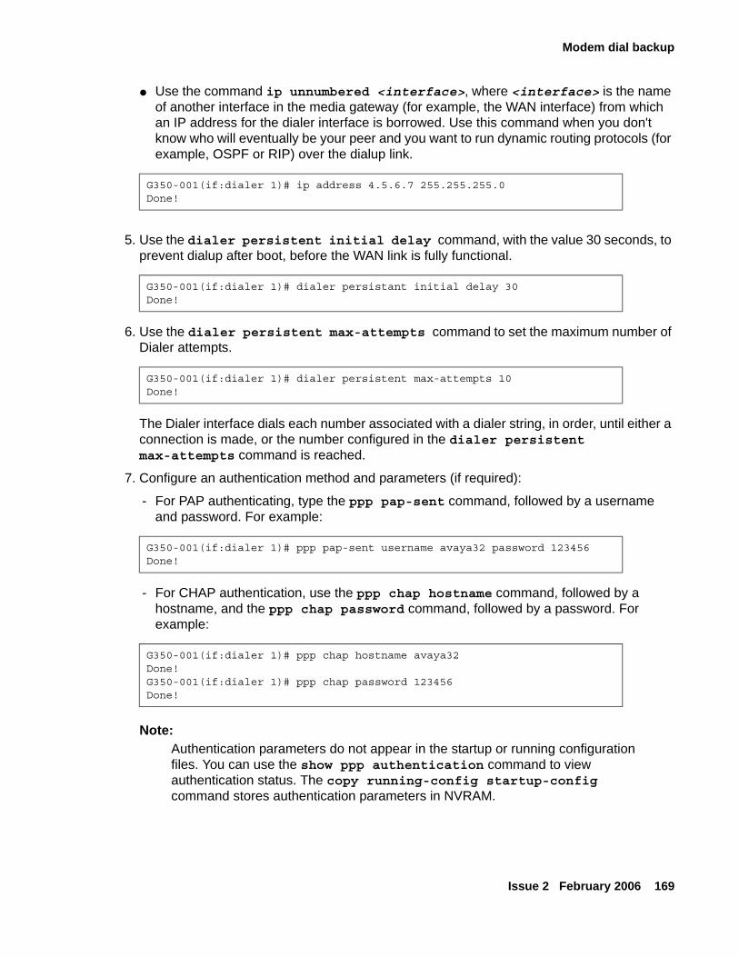
Modem dial backup
Issue 2 February 2006 169
● Use the command ip unnumbered <interface>, where <interface> is the name of another interface in the media gateway (for example, the WAN interface) from which an IP address for the dialer interface is borrowed. Use this command when you don't know who will eventually be your peer and you want to run dynamic routing protocols (for example, OSPF or RIP) over the dialup link.
5. Use the dialer persistent initial delay command, with the value 30 seconds, to prevent dialup after boot, before the WAN link is fully functional.
6. Use the dialer persistent max-attempts command to set the maximum number of Dialer attempts.
The Dialer interface dials each number associated with a dialer string, in order, until either a connection is made, or the number configured in the dialer persistent max-attempts command is reached.
7. Configure an authentication method and parameters (if required):
- For PAP authenticating, type the ppp pap-sent command, followed by a username and password. For example:
- For CHAP authentication, use the ppp chap hostname command, followed by a hostname, and the ppp chap password command, followed by a password. For example:
Note:Note: Authentication parameters do not appear in the startup or running configuration
files. You can use the show ppp authentication command to view authentication status. The copy running-config startup-config command stores authentication parameters in NVRAM.
G350-001(if:dialer 1)# ip address 4.5.6.7 255.255.255.0Done!
G350-001(if:dialer 1)# dialer persistant initial delay 30Done!
G350-001(if:dialer 1)# dialer persistent max-attempts 10Done!
G350-001(if:dialer 1)# ppp pap-sent username avaya32 password 123456Done!
G350-001(if:dialer 1)# ppp chap hostname avaya32Done!G350-001(if:dialer 1)# ppp chap password 123456Done!
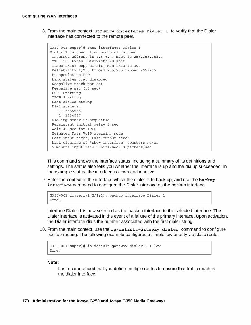
Configuring WAN interfaces
170 Administration for the Avaya G250 and Avaya G350 Media Gateways
8. From the main context, use show interfaces Dialer 1 to verify that the Dialer interface has connected to the remote peer.
This command shows the interface status, including a summary of its definitions and settings. The status also tells you whether the interface is up and the dialup succeeded. In the example status, the interface is down and inactive.
9. Enter the context of the interface which the dialer is to back up, and use the backup interface command to configure the Dialer interface as the backup interface.
Interface Dialer 1 is now selected as the backup interface to the selected interface. The Dialer interface is activated in the event of a failure of the primary interface. Upon activation, the Dialer interface dials the number associated with the first dialer string.
10. From the main context, use the ip-default-gateway dialer command to configure backup routing. The following example configures a simple low priority via static route.
Note:Note: It is recommended that you define multiple routes to ensure that traffic reaches
the dialer interface.
G350-001(super)# show interfaces Dialer 1Dialer 1 is down, line protocol is down Internet address is 4.5.6.7, mask is 255.255.255.0 MTU 1500 bytes, Bandwidth 28 kbit IPSec PMTU: copy df-bit, Min PMTU is 300 Reliability 1/255 txLoad 255/255 rxLoad 255/255 Encapsulation PPP Link status trap disabled Keepalive track not set Keepalive set (10 sec) LCP Starting IPCP Starting Last dialed string: Dial strings: 1: 5555555 2: 1234567 Dialing order is sequential Persistent initial delay 5 sec Wait 45 sec for IPCP Weighted Fair VoIP queueing mode Last input never, Last output never Last clearing of 'show interface' counters never 5 minute input rate 0 bits/sec, 0 packets/sec
G350-001(if:serial 2/1:1)# backup interface Dialer 1Done!
G350-001(super)# ip default-gateway dialer 1 1 lowDone!
Modem dial backup
Issue 2 February 2006 171
Modem dial backup interactions with other featuresOptimal modem dial backup configuration is a complex undertaking, dependent on a large number of factors. For an extensive discussion of network design, capacity planning, routing configuration, device configuration, and security considerations, see Application Note - VoIP Network Resiliency. Device and network configuration features that need to be taken into account include:
● The backup interface command allows you to designate the Dialer interface as the backup to an existing WAN interface on the G250/G350. When the G250/G350 reports the primary WAN interface down for a specified period of time, the Dialer interface is automatically activated and the modem dials. For more information on the backup interface command, see Backup interfaces on page 162.
● The G250/G350’s console port is an RJ-45 asynchronous port that can be used to support the modem for dial backup. Thus the dialer can utilize the same serial modem that is used for remote access to the device. Asynchronous dialing and modem recognition options must be set on the console port to support creation of the Dialer interface. For more information on configuring the console port, see Configuring the console port for modem use on page 143.
● The Dialer interface supports PAP and CHAP authentication for PPP connections. In addition, the Dialer interface can be configured to be a member of a VPN, allowing encryption of the modem traffic. Van Jacobsen compression is available for encrypted traffic over the Dialer interface, allowing optimal use of bandwidth. For more information on configuring PPP authentication and encryption, see Configuring PPP on page 155. For more information on heading compression, see Configuring header compression on page 134.
● It is recommended to filter traffic through the Dialer interface to permit only those packets necessary for continued interaction with the Avaya Communication Manager server. Filtering can be accomplished using access control lists, which specify traffic permissible through a selected interface. For more information on configuring access control lists, see Chapter 20: Configuring policy on page 463.
● Dynamic CAC can be used in conjunction with IGAR to provide a stable backup path for continued IP phone function in the event of a dial backup scenario. Dynamic CAC notifies the Avaya Communication Manager server that no bandwidth is available for bearer traffic, keeping the dial circuit from becoming fully congested. IGAR provides a path for gateway-to-gateway traffic destined for a remote Avaya Communication Manager server by forcing voice calls to and from the branch office to use the PSTN for bearer traffic. For more information on configuring Dynamic CAC, see Dynamic CAC on page 186. For more information on configuring IGAR, see Administrator Guide for Avaya Communication Manager, 03-300509.
Configuring WAN interfaces
172 Administration for the Avaya G250 and Avaya G350 Media Gateways
● Static IP addressing for the Dialer interface may not be feasible. Dynamic IP addressing is available to enable you to connect to the remote network through an ISP. ISPs commonly provide IP addressing for connected ports on an as-needed basis. IP unnumbered links are available to supply addressing in situations where you wish to run routing over your network link without committing a subnet. For information on configuring dynamic IP addressing, see Using dynamic local peer IP on page 413. For information on configuring unnumbered IP, see Configuring unnumbered IP interfaces on page 337.
● Object tracking can be used with the Loopback interface to provide an alternative method for activating the Dialer interface when connectivity with the main office is lost. This is useful in configurations where the WAN interface is not connected directly to the G250/G350. Use object tracking to configure RTRs to verify connectivity with the main office. If the RTR fails, the object tracker can be configured to change the status of the Loopback interface to down. If the Dialer interface is configured as the backup for the Loopback interface, the Dialer interface will automatically dial when connectivity fails. For more information about object tracking, see Object tracking on page 187.
Note:Note: In a situation where the same modem is used for inbound Avaya Service calls
and outbound dial backup calls, only one call can be active at any time.
Note:Note: Refer to www.multitech.com for a listing of modem AT commands used to
configure the modem directly.
● You must disable modem dial backup before configuring FIPS.
Configuration exampleThis example sets up a modem dial backup for the WAN link between a branch office and the headquarters data center. The branch office is connected to the corporate network using a G250. IP phone users in the branch office connect to an MGC located in the headquarters data center, and there is an RAS located in the headquarters data center, with multiple phone lines available for dial access. The primary WAN connection is a PPP link connected to the port Serial 2/1. The dialer PPP session uses CHAP encryption. The corporate network is routed using OSPF. An analog trunk connects the branch office to the PSTN for non-corporate bearer traffic.Figure 17 shows the network topology.
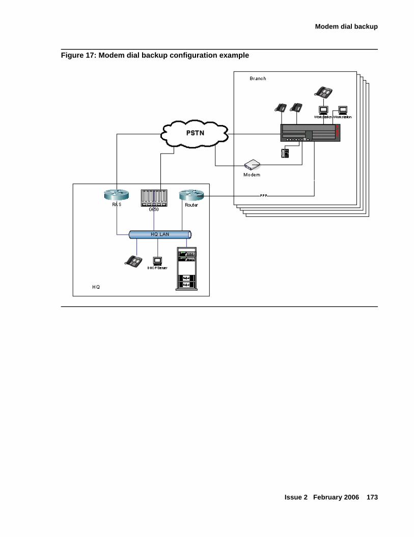
Modem dial backup
Issue 2 February 2006 173
Figure 17: Modem dial backup configuration example
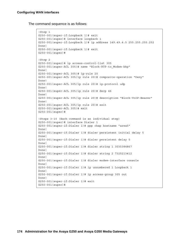
Configuring WAN interfaces
174 Administration for the Avaya G250 and Avaya G350 Media Gateways
The command sequence is as follows:
!Step 1G250-001(super-if:Loopback 1)# exitG250-001(super)# interface loopback 1G250-001(super-if:Loopback 1)# ip address 149.49.4.5 255.255.255.252Done!G250-001(super-if:Loopback 1)# exitG250-001(super)#
!Step 2G250-001(super)# ip access-control-list 305G250-001(super-ACL 305)# name "Block-RTP-to_Modem-bkp"Done!G250-001(super-ACL 305)# ip-rule 20G250-001(super-ACL 305/ip rule 20)# composite-operation "Deny"Done!G250-001(super-ACL 305/ip rule 20)# ip-protocol udpDone!G250-001(super-ACL 305/ip rule 20)# dscp 46Done!G250-001(super-ACL 305/ip rule 20)# description "Block-VoIP-Bearer"Done!G250-001(super-ACL 305/ip rule 20)# exitG250-001(super-ACL 305)# exitG250-001(super)#
!Steps 3-10 (Each command is an individual step)G250-001(super)# interface Dialer 1G250-001(super-if:Dialer 1)# ppp chap hostname "area5"Done!G250-001(super-if:Dialer 1)# dialer persistent initial delay 5Done!G250-001(super-if:Dialer 1)# dialer persistent delay 5Done!G250-001(super-if:Dialer 1)# dialer string 1 3035384867Done!G250-001(super-if:Dialer 1)# dialer string 2 7325213412Done!G250-001(super-if:Dialer 1)# dialer modem-interface consoleDone!G250-001(super-if:Dialer 1)# ip unnumbered 1 Loopback 1Done!G250-001(super-if:Dialer 1)# ip access-group 305 outDone!G250-001(super-if:Dialer 1)# exitG250-001(super)#
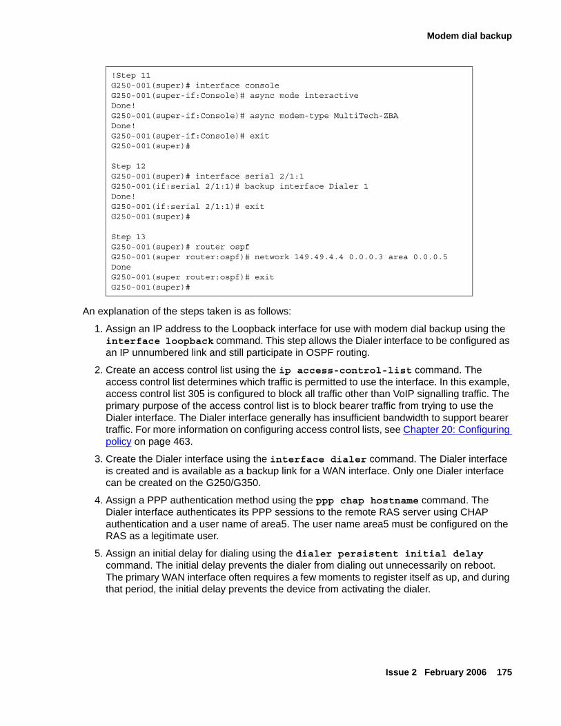
Modem dial backup
Issue 2 February 2006 175
An explanation of the steps taken is as follows:
1. Assign an IP address to the Loopback interface for use with modem dial backup using the interface loopback command. This step allows the Dialer interface to be configured as an IP unnumbered link and still participate in OSPF routing.
2. Create an access control list using the ip access-control-list command. The access control list determines which traffic is permitted to use the interface. In this example, access control list 305 is configured to block all traffic other than VoIP signalling traffic. The primary purpose of the access control list is to block bearer traffic from trying to use the Dialer interface. The Dialer interface generally has insufficient bandwidth to support bearer traffic. For more information on configuring access control lists, see Chapter 20: Configuring policy on page 463.
3. Create the Dialer interface using the interface dialer command. The Dialer interface is created and is available as a backup link for a WAN interface. Only one Dialer interface can be created on the G250/G350.
4. Assign a PPP authentication method using the ppp chap hostname command. The Dialer interface authenticates its PPP sessions to the remote RAS server using CHAP authentication and a user name of area5. The user name area5 must be configured on the RAS as a legitimate user.
5. Assign an initial delay for dialing using the dialer persistent initial delay command. The initial delay prevents the dialer from dialing out unnecessarily on reboot. The primary WAN interface often requires a few moments to register itself as up, and during that period, the initial delay prevents the device from activating the dialer.
!Step 11G250-001(super)# interface consoleG250-001(super-if:Console)# async mode interactiveDone!G250-001(super-if:Console)# async modem-type MultiTech-ZBADone!G250-001(super-if:Console)# exitG250-001(super)#
Step 12G250-001(super)# interface serial 2/1:1G250-001(if:serial 2/1:1)# backup interface Dialer 1Done!G250-001(if:serial 2/1:1)# exitG250-001(super)#
Step 13G250-001(super)# router ospfG250-001(super router:ospf)# network 149.49.4.4 0.0.0.3 area 0.0.0.5DoneG250-001(super router:ospf)# exitG250-001(super)#
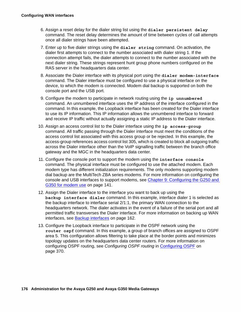
Configuring WAN interfaces
176 Administration for the Avaya G250 and Avaya G350 Media Gateways
6. Assign a reset delay for the dialer string list using the dialer persistent delay command. The reset delay determines the amount of time between cycles of call attempts once all dialer strings have been attempted.
7. Enter up to five dialer strings using the dialer string command. On activation, the dialer first attempts to connect to the number associated with dialer string 1. If the connection attempt fails, the dialer attempts to connect to the number associated with the next dialer string. These strings represent hunt group phone numbers configured on the RAS server in the headquarters data center.
8. Associate the Dialer interface with its physical port using the dialer modem-interface command. The Dialer interface must be configured to use a physical interface on the device, to which the modem is connected. Modem dial backup is supported on both the console port and the USB port.
9. Configure the modem to participate in network routing using the ip unnumbered command. An unnumbered interface uses the IP address of the interface configured in the command. In this example, the Loopback interface has been created for the Dialer interface to use its IP information. This IP information allows the unnumbered interface to forward and receive IP traffic without actually assigning a static IP address to the Dialer interface.
10. Assign an access control list to the Dialer interface using the ip access-group command. All traffic passing through the Dialer interface must meet the conditions of the access control list associated with this access group or be rejected. In this example, the access-group references access control list 305, which is created to block all outgoing traffic across the Dialer interface other than the VoIP signalling traffic between the branch office gateway and the MGC in the headquarters data center.
11. Configure the console port to support the modem using the interface console command. The physical interface must be configured to use the attached modem. Each modem type has different initialization requirements. The only modems supporting modem dial backup are the MultiTech ZBA series modems. For more information on configuring the console and USB interfaces to support modems, see Chapter 9: Configuring the G250 and G350 for modem use on page 141.
12. Assign the Dialer interface to the interface you want to back up using the backup interface dialer command. In this example, interface dialer 1 is selected as the backup interface to interface serial 2/1:1, the primary WAN connection to the headquarters network. The dialer activates in the event of a failure of the serial port and all permitted traffic transverses the Dialer interface. For more information on backing up WAN interfaces, see Backup interfaces on page 162.
13. Configure the Loopback interface to participate in the OSPF network using the router ospf command. In this example, a group of branch offices are assigned to OSPF area 5. This configuration allows filtering to take place at the border points and minimizes topology updates on the headquarters data center routers. For more information on configuring OSPF routing, see Configuring OSPF routing in Configuring OSPF on page 370.
Modem dial backup
Issue 2 February 2006 177
Modem dial backup maintenanceThe G250/G350 generates specific log messages for Dialer interface activity when configured to do so. Certain dialer-related log messages are generated to aid you in troubleshooting problems with modem dial backup. In addition, messages generated by the modem and the PPP session are available to help with troubleshooting modem dial backup issues. To activate session logging for modem dial backup functions, type the following commands. Logging messages will be sent to the terminal screen.
Note:Note: Syslog and log file logging are also available. See Chapter 7: Configuring
logging on page 119.
● set logging session condition dialer information
● set logging session condition console information
● set logging session condition usb-modem information
● set logging session condition ppp information
Note:Note: Not all logging messages indicate a trouble condition. Some are generated to
provide information on normal working activity of the Dialer interface. For more information on logging configuration, see Chapter 7: Configuring logging on page 119.
The set logging commands must include a severity level. All logging messages with the specified severity and higher are displayed. The following are the available severity levels:
● Information - This message is for informational purposes and requires no action on your part.
● Debug - This message provides information that can be useful in debugging certain problems, but requires no action itself.
● Warning - This message indicates a condition requiring user intervention and troubleshooting.
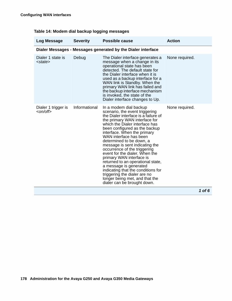
Configuring WAN interfaces
178 Administration for the Avaya G250 and Avaya G350 Media Gateways
Table 14: Modem dial backup logging messages
Log Message Severity Possible cause Action
Dialer Messages - Messages generated by the Dialer interface
Dialer 1 state is <state>
Debug The Dialer interface generates a message when a change in its operational state has been detected. The default state for the Dialer interface when it is used as a backup interface for a WAN link is Standby. When the primary WAN link has failed and the backup interface mechanism is invoked, the state of the Dialer interface changes to Up.
None required.
Dialer 1 trigger is <on/off>
Informational In a modem dial backup scenario, the event triggering the Dialer interface is a failure of the primary WAN interface for which the Dialer interface has been configured as the backup interface. When the primary WAN interface has been determined to be down, a message is sent indicating the occurrence of the triggering event for the dialer. When the primary WAN interface is returned to an operational state, a message is generated indicating that the conditions for triggering the dialer are no longer being met, and that the dialer can be brought down.
None required.
1 of 6
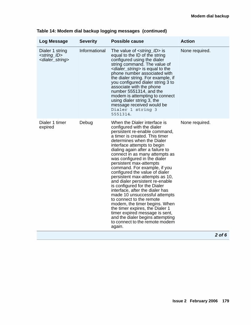
Modem dial backup
Issue 2 February 2006 179
Dialer 1 string <string_ID> <dialer_string>
Informational The value of <string_ID> is equal to the ID of the string configured using the dialer string command. The value of <dialer_string> is equal to the phone number associated with the dialer string. For example, if you configured dialer string 3 to associate with the phone number 5551314, and the modem is attempting to connect using dialer string 3, the message received would be Dialer 1 string 3 5551314.
None required.
Dialer 1 timer expired
Debug When the Dialer interface is configured with the dialer persistent re-enable command, a timer is created. This timer determines when the Dialer interface attempts to begin dialing again after a failure to connect in as many attempts as was configured in the dialer persistent max-attempts command. For example, if you configured the value of dialer persistent max-attempts as 10, and dialer persistent re-enable is configured for the Dialer interface, after the dialer has made 10 unsuccessful attempts to connect to the remote modem, the timer begins. When the timer expires, the Dialer 1 timer expired message is sent, and the dialer begins attempting to connect to the remote modem again.
None required.
Table 14: Modem dial backup logging messages (continued)
Log Message Severity Possible cause Action
2 of 6
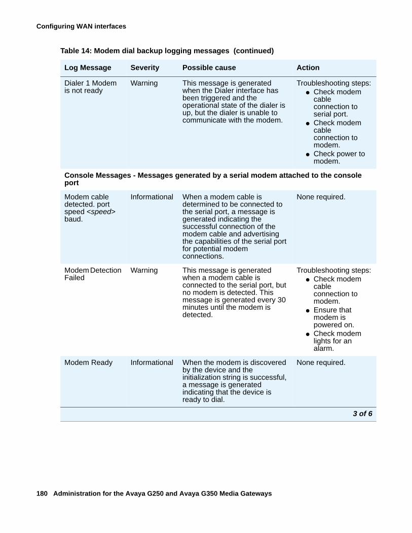
Configuring WAN interfaces
180 Administration for the Avaya G250 and Avaya G350 Media Gateways
Dialer 1 Modem is not ready
Warning This message is generated when the Dialer interface has been triggered and the operational state of the dialer is up, but the dialer is unable to communicate with the modem.
Troubleshooting steps:● Check modem
cable connection to serial port.
● Check modem cable connection to modem.
● Check power to modem.
Console Messages - Messages generated by a serial modem attached to the console port
Modem cable detected. port speed <speed> baud.
Informational When a modem cable is determined to be connected to the serial port, a message is generated indicating the successful connection of the modem cable and advertising the capabilities of the serial port for potential modem connections.
None required.
Modem Detection Failed
Warning This message is generated when a modem cable is connected to the serial port, but no modem is detected. This message is generated every 30 minutes until the modem is detected.
Troubleshooting steps:● Check modem
cable connection to modem.
● Ensure that modem is powered on.
● Check modem lights for an alarm.
Modem Ready Informational When the modem is discovered by the device and the initialization string is successful, a message is generated indicating that the device is ready to dial.
None required.
Table 14: Modem dial backup logging messages (continued)
Log Message Severity Possible cause Action
3 of 6
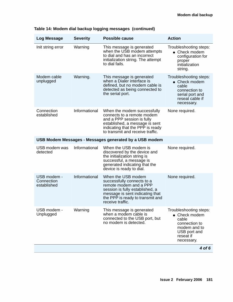
Modem dial backup
Issue 2 February 2006 181
Init string error Warning This message is generated when the USB modem attempts to dial and has an incorrect initialization string. The attempt to dial fails.
Troubleshooting steps:● Check modem
configuration for proper initialization string.
Modem cable unplugged
Warning. This message is generated when a Dialer interface is defined, but no modem cable is detected as being connected to the serial port.
Troubleshooting steps:● Check modem
cable connection to serial port and reseat cable if necessary.
Connection established
Informational When the modem successfully connects to a remote modem and a PPP session is fully established, a message is sent indicating that the PPP is ready to transmit and receive traffic.
None required.
USB Modem Messages - Messages generated by a USB modem
USB modem was detected
Informational When the USB modem is discovered by the device and the initialization string is successful, a message is generated indicating that the device is ready to dial.
None required.
USB modem - Connection established
Informational When the USB modem successfully connects to a remote modem and a PPP session is fully established, a message is sent indicating that the PPP is ready to transmit and receive traffic.
None required.
USB modem - Unplugged
Warning This message is generated when a modem cable is connected to the USB port, but no modem is detected.
Troubleshooting steps:● Check modem
cable connection to modem and to USB port and reseat if necessary.
Table 14: Modem dial backup logging messages (continued)
Log Message Severity Possible cause Action
4 of 6
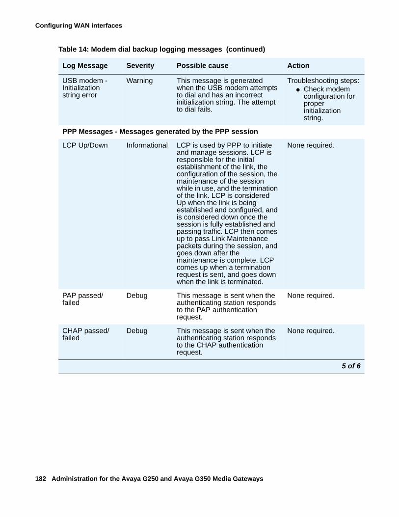
Configuring WAN interfaces
182 Administration for the Avaya G250 and Avaya G350 Media Gateways
USB modem - Initialization string error
Warning This message is generated when the USB modem attempts to dial and has an incorrect initialization string. The attempt to dial fails.
Troubleshooting steps:● Check modem
configuration for proper initialization string.
PPP Messages - Messages generated by the PPP session
LCP Up/Down Informational LCP is used by PPP to initiate and manage sessions. LCP is responsible for the initial establishment of the link, the configuration of the session, the maintenance of the session while in use, and the termination of the link. LCP is considered Up when the link is being established and configured, and is considered down once the session is fully established and passing traffic. LCP then comes up to pass Link Maintenance packets during the session, and goes down after the maintenance is complete. LCP comes up when a termination request is sent, and goes down when the link is terminated.
None required.
PAP passed/failed
Debug This message is sent when the authenticating station responds to the PAP authentication request.
None required.
CHAP passed/failed
Debug This message is sent when the authenticating station responds to the CHAP authentication request.
None required.
Table 14: Modem dial backup logging messages (continued)
Log Message Severity Possible cause Action
5 of 6
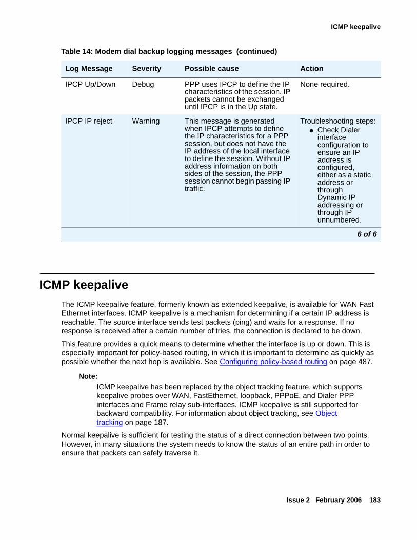
ICMP keepalive
Issue 2 February 2006 183
ICMP keepaliveThe ICMP keepalive feature, formerly known as extended keepalive, is available for WAN Fast Ethernet interfaces. ICMP keepalive is a mechanism for determining if a certain IP address is reachable. The source interface sends test packets (ping) and waits for a response. If no response is received after a certain number of tries, the connection is declared to be down.
This feature provides a quick means to determine whether the interface is up or down. This is especially important for policy-based routing, in which it is important to determine as quickly as possible whether the next hop is available. See Configuring policy-based routing on page 487.
Note:Note: ICMP keepalive has been replaced by the object tracking feature, which supports
keepalive probes over WAN, FastEthernet, loopback, PPPoE, and Dialer PPP interfaces and Frame relay sub-interfaces. ICMP keepalive is still supported for backward compatibility. For information about object tracking, see Object tracking on page 187.
Normal keepalive is sufficient for testing the status of a direct connection between two points. However, in many situations the system needs to know the status of an entire path in order to ensure that packets can safely traverse it.
IPCP Up/Down Debug PPP uses IPCP to define the IP characteristics of the session. IP packets cannot be exchanged until IPCP is in the Up state.
None required.
IPCP IP reject Warning This message is generated when IPCP attempts to define the IP characteristics for a PPP session, but does not have the IP address of the local interface to define the session. Without IP address information on both sides of the session, the PPP session cannot begin passing IP traffic.
Troubleshooting steps:● Check Dialer
interface configuration to ensure an IP address is configured, either as a static address or through Dynamic IP addressing or through IP unnumbered.
Table 14: Modem dial backup logging messages (continued)
Log Message Severity Possible cause Action
6 of 6
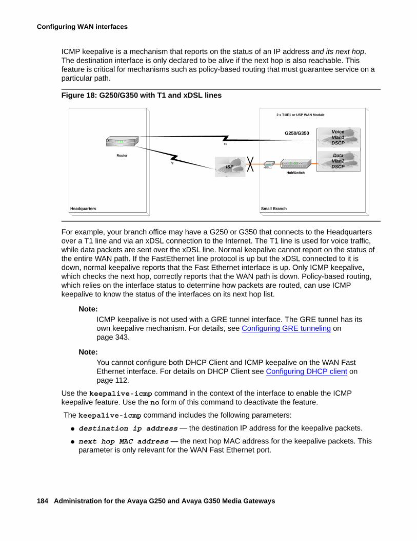
Configuring WAN interfaces
184 Administration for the Avaya G250 and Avaya G350 Media Gateways
ICMP keepalive is a mechanism that reports on the status of an IP address and its next hop. The destination interface is only declared to be alive if the next hop is also reachable. This feature is critical for mechanisms such as policy-based routing that must guarantee service on a particular path.
Figure 18: G250/G350 with T1 and xDSL lines
For example, your branch office may have a G250 or G350 that connects to the Headquarters over a T1 line and via an xDSL connection to the Internet. The T1 line is used for voice traffic, while data packets are sent over the xDSL line. Normal keepalive cannot report on the status of the entire WAN path. If the FastEthernet line protocol is up but the xDSL connected to it is down, normal keepalive reports that the Fast Ethernet interface is up. Only ICMP keepalive, which checks the next hop, correctly reports that the WAN path is down. Policy-based routing, which relies on the interface status to determine how packets are routed, can use ICMP keepalive to know the status of the interfaces on its next hop list.
Note:Note: ICMP keepalive is not used with a GRE tunnel interface. The GRE tunnel has its
own keepalive mechanism. For details, see Configuring GRE tunneling on page 343.
Note:Note: You cannot configure both DHCP Client and ICMP keepalive on the WAN Fast
Ethernet interface. For details on DHCP Client see Configuring DHCP client on page 112.
Use the keepalive-icmp command in the context of the interface to enable the ICMP keepalive feature. Use the no form of this command to deactivate the feature.
The keepalive-icmp command includes the following parameters:
● destination ip address — the destination IP address for the keepalive packets.
● next hop MAC address — the next hop MAC address for the keepalive packets. This parameter is only relevant for the WAN Fast Ethernet port.
2 x T1/E1 or USP WAN Module
Small Branch
Hub/Switch
S8300
xDSL1ISP
DataVlan2DSCP
VoiceVlan1DSCP
Headquarters
T1
T1
Router
G250/G350
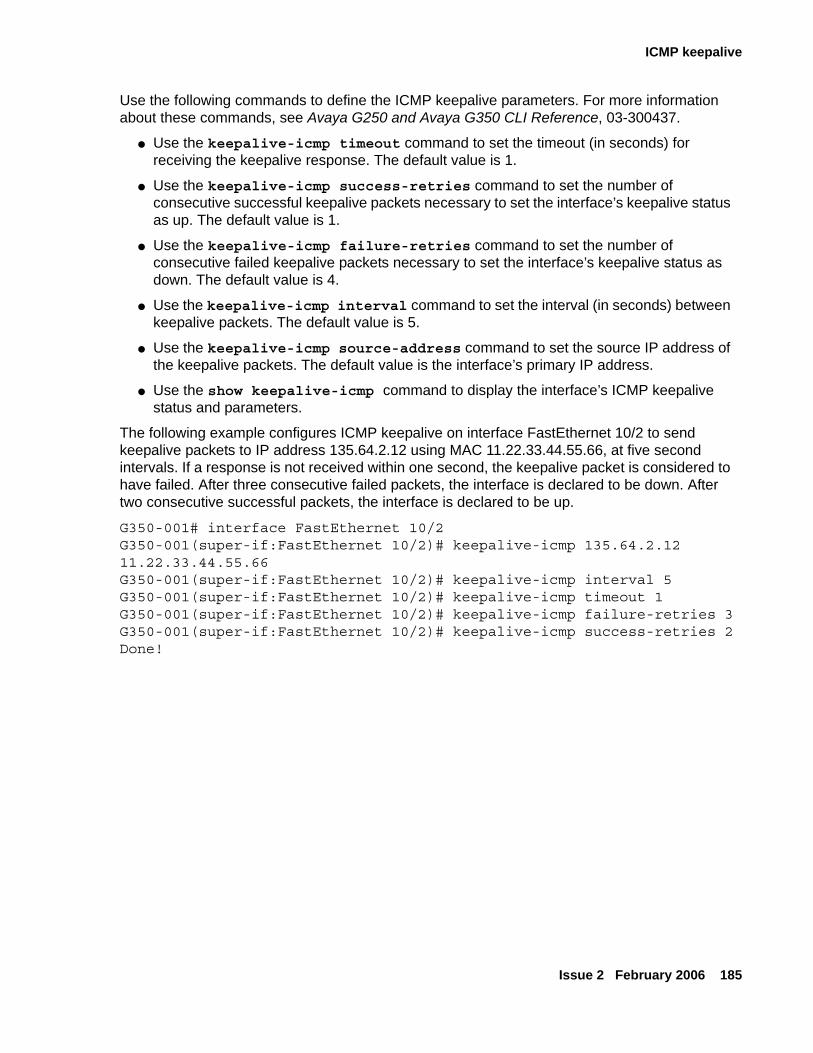
ICMP keepalive
Issue 2 February 2006 185
Use the following commands to define the ICMP keepalive parameters. For more information about these commands, see Avaya G250 and Avaya G350 CLI Reference, 03-300437.
● Use the keepalive-icmp timeout command to set the timeout (in seconds) for receiving the keepalive response. The default value is 1.
● Use the keepalive-icmp success-retries command to set the number of consecutive successful keepalive packets necessary to set the interface’s keepalive status as up. The default value is 1.
● Use the keepalive-icmp failure-retries command to set the number of consecutive failed keepalive packets necessary to set the interface’s keepalive status as down. The default value is 4.
● Use the keepalive-icmp interval command to set the interval (in seconds) between keepalive packets. The default value is 5.
● Use the keepalive-icmp source-address command to set the source IP address of the keepalive packets. The default value is the interface’s primary IP address.
● Use the show keepalive-icmp command to display the interface’s ICMP keepalive status and parameters.
The following example configures ICMP keepalive on interface FastEthernet 10/2 to send keepalive packets to IP address 135.64.2.12 using MAC 11.22.33.44.55.66, at five second intervals. If a response is not received within one second, the keepalive packet is considered to have failed. After three consecutive failed packets, the interface is declared to be down. After two consecutive successful packets, the interface is declared to be up.
G350-001# interface FastEthernet 10/2G350-001(super-if:FastEthernet 10/2)# keepalive-icmp 135.64.2.12 11.22.33.44.55.66G350-001(super-if:FastEthernet 10/2)# keepalive-icmp interval 5G350-001(super-if:FastEthernet 10/2)# keepalive-icmp timeout 1G350-001(super-if:FastEthernet 10/2)# keepalive-icmp failure-retries 3G350-001(super-if:FastEthernet 10/2)# keepalive-icmp success-retries 2Done!
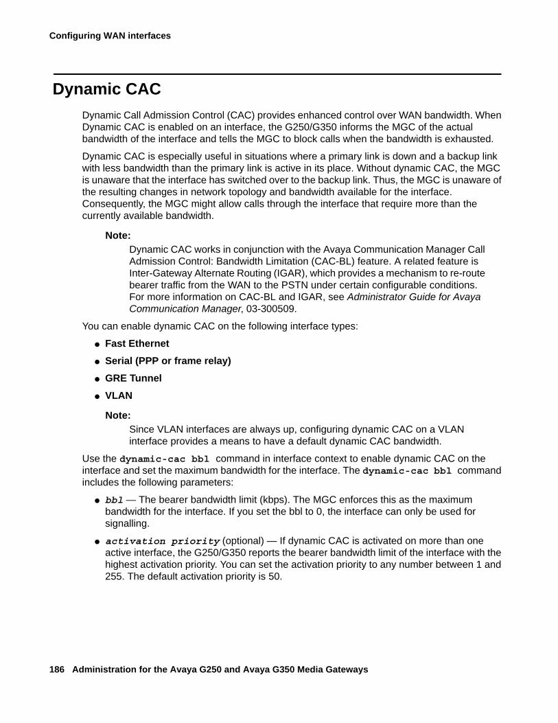
Configuring WAN interfaces
186 Administration for the Avaya G250 and Avaya G350 Media Gateways
Dynamic CACDynamic Call Admission Control (CAC) provides enhanced control over WAN bandwidth. When Dynamic CAC is enabled on an interface, the G250/G350 informs the MGC of the actual bandwidth of the interface and tells the MGC to block calls when the bandwidth is exhausted.
Dynamic CAC is especially useful in situations where a primary link is down and a backup link with less bandwidth than the primary link is active in its place. Without dynamic CAC, the MGC is unaware that the interface has switched over to the backup link. Thus, the MGC is unaware of the resulting changes in network topology and bandwidth available for the interface. Consequently, the MGC might allow calls through the interface that require more than the currently available bandwidth.
Note:Note: Dynamic CAC works in conjunction with the Avaya Communication Manager Call
Admission Control: Bandwidth Limitation (CAC-BL) feature. A related feature is Inter-Gateway Alternate Routing (IGAR), which provides a mechanism to re-route bearer traffic from the WAN to the PSTN under certain configurable conditions. For more information on CAC-BL and IGAR, see Administrator Guide for Avaya Communication Manager, 03-300509.
You can enable dynamic CAC on the following interface types:
● Fast Ethernet ● Serial (PPP or frame relay) ● GRE Tunnel● VLAN
Note:Note: Since VLAN interfaces are always up, configuring dynamic CAC on a VLAN
interface provides a means to have a default dynamic CAC bandwidth.
Use the dynamic-cac bbl command in interface context to enable dynamic CAC on the interface and set the maximum bandwidth for the interface. The dynamic-cac bbl command includes the following parameters:
● bbl — The bearer bandwidth limit (kbps). The MGC enforces this as the maximum bandwidth for the interface. If you set the bbl to 0, the interface can only be used for signalling.
● activation priority (optional) — If dynamic CAC is activated on more than one active interface, the G250/G350 reports the bearer bandwidth limit of the interface with the highest activation priority. You can set the activation priority to any number between 1 and 255. The default activation priority is 50.
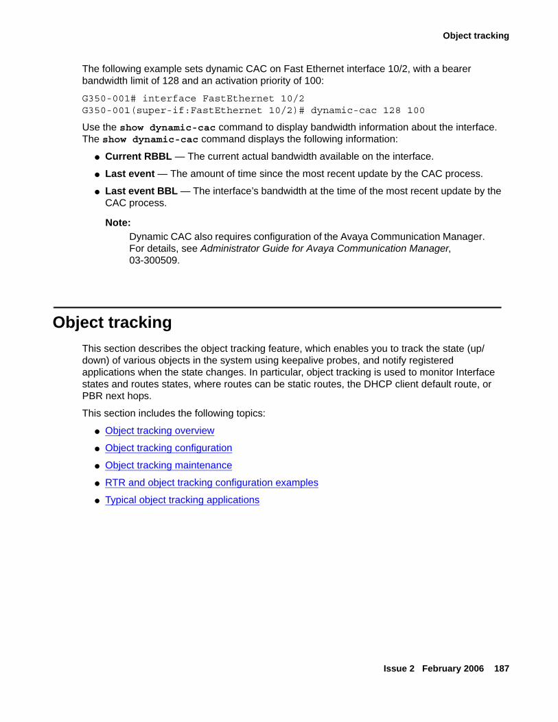
Object tracking
Issue 2 February 2006 187
The following example sets dynamic CAC on Fast Ethernet interface 10/2, with a bearer bandwidth limit of 128 and an activation priority of 100:
G350-001# interface FastEthernet 10/2G350-001(super-if:FastEthernet 10/2)# dynamic-cac 128 100
Use the show dynamic-cac command to display bandwidth information about the interface. The show dynamic-cac command displays the following information:
● Current RBBL — The current actual bandwidth available on the interface.
● Last event — The amount of time since the most recent update by the CAC process.
● Last event BBL — The interface’s bandwidth at the time of the most recent update by the CAC process.
Note:Note: Dynamic CAC also requires configuration of the Avaya Communication Manager.
For details, see Administrator Guide for Avaya Communication Manager, 03-300509.
Object trackingThis section describes the object tracking feature, which enables you to track the state (up/down) of various objects in the system using keepalive probes, and notify registered applications when the state changes. In particular, object tracking is used to monitor Interface states and routes states, where routes can be static routes, the DHCP client default route, or PBR next hops.
This section includes the following topics:
● Object tracking overview
● Object tracking configuration
● Object tracking maintenance
● RTR and object tracking configuration examples
● Typical object tracking applications
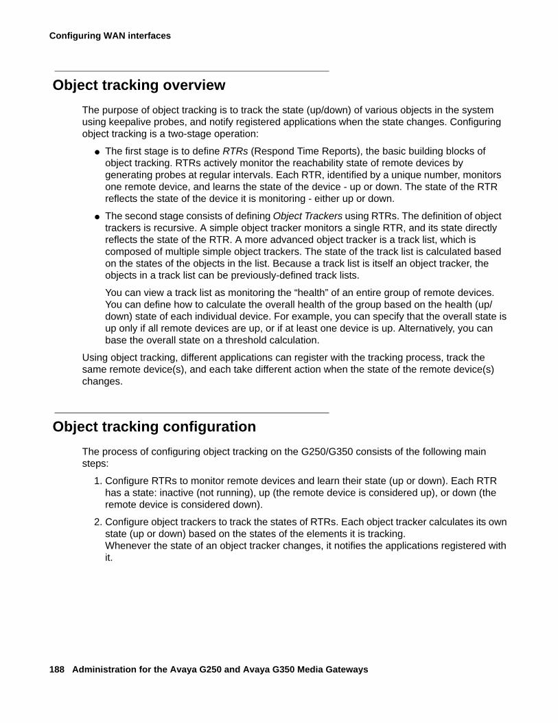
Configuring WAN interfaces
188 Administration for the Avaya G250 and Avaya G350 Media Gateways
Object tracking overviewThe purpose of object tracking is to track the state (up/down) of various objects in the system using keepalive probes, and notify registered applications when the state changes. Configuring object tracking is a two-stage operation:
● The first stage is to define RTRs (Respond Time Reports), the basic building blocks of object tracking. RTRs actively monitor the reachability state of remote devices by generating probes at regular intervals. Each RTR, identified by a unique number, monitors one remote device, and learns the state of the device - up or down. The state of the RTR reflects the state of the device it is monitoring - either up or down.
● The second stage consists of defining Object Trackers using RTRs. The definition of object trackers is recursive. A simple object tracker monitors a single RTR, and its state directly reflects the state of the RTR. A more advanced object tracker is a track list, which is composed of multiple simple object trackers. The state of the track list is calculated based on the states of the objects in the list. Because a track list is itself an object tracker, the objects in a track list can be previously-defined track lists.
You can view a track list as monitoring the “health” of an entire group of remote devices. You can define how to calculate the overall health of the group based on the health (up/down) state of each individual device. For example, you can specify that the overall state is up only if all remote devices are up, or if at least one device is up. Alternatively, you can base the overall state on a threshold calculation.
Using object tracking, different applications can register with the tracking process, track the same remote device(s), and each take different action when the state of the remote device(s) changes.
Object tracking configurationThe process of configuring object tracking on the G250/G350 consists of the following main steps:
1. Configure RTRs to monitor remote devices and learn their state (up or down). Each RTR has a state: inactive (not running), up (the remote device is considered up), or down (the remote device is considered down).
2. Configure object trackers to track the states of RTRs. Each object tracker calculates its own state (up or down) based on the states of the elements it is tracking. Whenever the state of an object tracker changes, it notifies the applications registered with it.
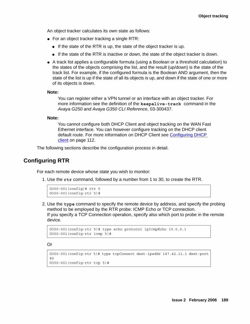
Object tracking
Issue 2 February 2006 189
An object tracker calculates its own state as follows:
● For an object tracker tracking a single RTR:
● If the state of the RTR is up, the state of the object tracker is up.
● If the state of the RTR is inactive or down, the state of the object tracker is down.
● A track list applies a configurable formula (using a Boolean or a threshold calculation) to the states of the objects comprising the list, and the result (up/down) is the state of the track list. For example, if the configured formula is the Boolean AND argument, then the state of the list is up if the state of all its objects is up, and down if the state of one or more of its objects is down.
Note:Note: You can register either a VPN tunnel or an interface with an object tracker. For
more information see the definition of the keepalive-track command in the Avaya G250 and Avaya G350 CLI Reference, 03-300437.
Note:Note: You cannot configure both DHCP Client and object tracking on the WAN Fast
Ethernet interface. You can however configure tracking on the DHCP client default route. For more information on DHCP Client see Configuring DHCP client on page 112.
The following sections describe the configuration process in detail.
Configuring RTR
For each remote device whose state you wish to monitor:
1. Use the rtr command, followed by a number from 1 to 30, to create the RTR.
2. Use the type command to specify the remote device by address, and specify the probing method to be employed by the RTR probe: ICMP Echo or TCP connection. If you specify a TCP Connection operation, specify also which port to probe in the remote device.
Or
G350-001(config)# rtr 5G350-001(config-rtr 5)#
G350-001(config-rtr 5)# type echo protocol ipIcmpEcho 10.0.0.1G350-001(config-rtr icmp 5)#
G350-001(config-rtr 5)# type tcpConnect dest-ipaddr 147.42.11.1 dest-port 80G350-001(config-rtr tcp 5)#
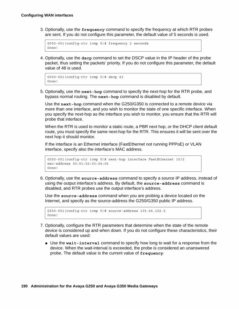
Configuring WAN interfaces
190 Administration for the Avaya G250 and Avaya G350 Media Gateways
3. Optionally, use the frequency command to specify the frequency at which RTR probes are sent. If you do not configure this parameter, the default value of 5 seconds is used.
4. Optionally, use the dscp command to set the DSCP value in the IP header of the probe packet, thus setting the packets’ priority. If you do not configure this parameter, the default value of 48 is used.
5. Optionally, use the next-hop command to specify the next-hop for the RTR probe, and bypass normal routing. The next-hop command is disabled by default.
Use the next-hop command when the G250/G350 is connected to a remote device via more than one interface, and you wish to monitor the state of one specific interface. When you specify the next-hop as the interface you wish to monitor, you ensure that the RTR will probe that interface.
When the RTR is used to monitor a static route, a PBR next hop, or the DHCP client default route, you must specify the same next-hop for the RTR. This ensures it will be sent over the next hop it should monitor.
If the interface is an Ethernet interface (FastEthernet not running PPPoE) or VLAN interface, specify also the interface’s MAC address.
6. Optionally, use the source-address command to specify a source IP address, instead of using the output interface’s address. By default, the source-address command is disabled, and RTR probes use the output interface’s address.
Use the source-address command when you are probing a device located on the Internet, and specify as the source-address the G250/G350 public IP address.
7. Optionally, configure the RTR parameters that determine when the state of the remote device is considered up and when down. If you do not configure these characteristics, their default values are used:
● Use the wait-interval command to specify how long to wait for a response from the device. When the wait-interval is exceeded, the probe is considered an unanswered probe. The default value is the current value of frequency.
G350-001(config-rtr icmp 5)# frequency 2 secondsDone!
G350-001(config-rtr icmp 5)# dscp 43Done!
G350-001(config-rtr icmp 5)# next-hop interface FastEthernet 10/2 mac-address 00:01:02:03:04:05Done!
G350-001(config-rtr icmp 5)# source-address 135.64.102.5Done!
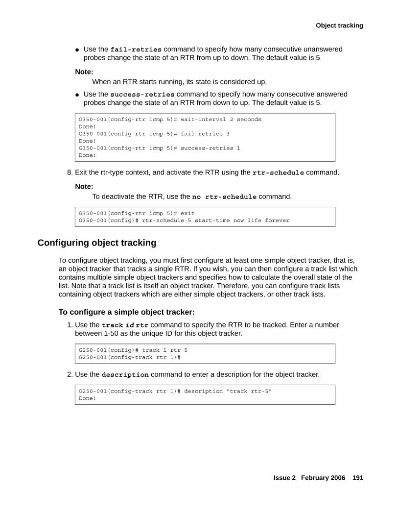
Object tracking
Issue 2 February 2006 191
● Use the fail-retries command to specify how many consecutive unanswered probes change the state of an RTR from up to down. The default value is 5
Note:Note: When an RTR starts running, its state is considered up.
● Use the success-retries command to specify how many consecutive answered probes change the state of an RTR from down to up. The default value is 5.
8. Exit the rtr-type context, and activate the RTR using the rtr-schedule command.
Note:Note: To deactivate the RTR, use the no rtr-schedule command.
Configuring object tracking
To configure object tracking, you must first configure at least one simple object tracker, that is, an object tracker that tracks a single RTR. If you wish, you can then configure a track list which contains multiple simple object trackers and specifies how to calculate the overall state of the list. Note that a track list is itself an object tracker. Therefore, you can configure track lists containing object trackers which are either simple object trackers, or other track lists.
To configure a simple object tracker:1. Use the track id rtr command to specify the RTR to be tracked. Enter a number
between 1-50 as the unique ID for this object tracker.
2. Use the description command to enter a description for the object tracker.
G350-001(config-rtr icmp 5)# wait-interval 2 secondsDone!G350-001(config-rtr icmp 5)# fail-retries 3Done!G350-001(config-rtr icmp 5)# success-retries 1Done!
G350-001(config-rtr icmp 5)# exitG350-001(config)# rtr-schedule 5 start-time now life forever
G250-001(config)# track 1 rtr 5G250-001(config-track rtr 1)#
G250-001(config-track rtr 1)# description "track rtr-5"Done!
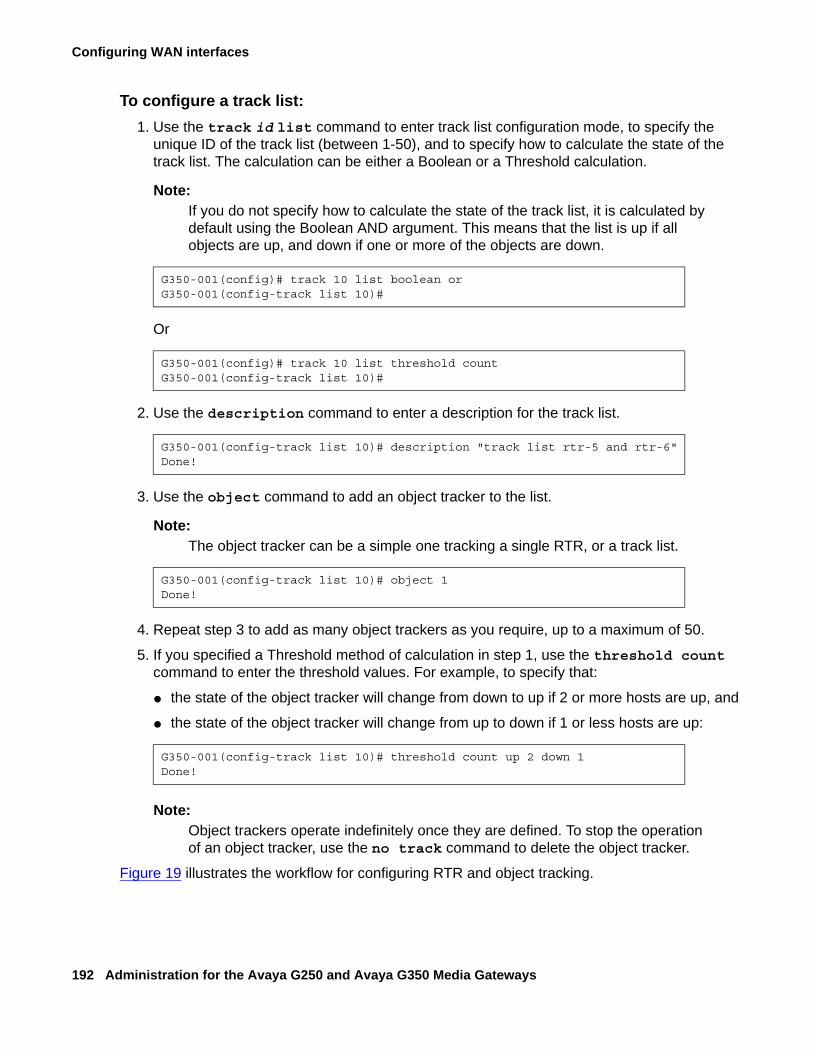
Configuring WAN interfaces
192 Administration for the Avaya G250 and Avaya G350 Media Gateways
To configure a track list:1. Use the track id list command to enter track list configuration mode, to specify the
unique ID of the track list (between 1-50), and to specify how to calculate the state of the track list. The calculation can be either a Boolean or a Threshold calculation.
Note:Note: If you do not specify how to calculate the state of the track list, it is calculated by
default using the Boolean AND argument. This means that the list is up if all objects are up, and down if one or more of the objects are down.
Or
2. Use the description command to enter a description for the track list.
3. Use the object command to add an object tracker to the list.
Note:Note: The object tracker can be a simple one tracking a single RTR, or a track list.
4. Repeat step 3 to add as many object trackers as you require, up to a maximum of 50.
5. If you specified a Threshold method of calculation in step 1, use the threshold count command to enter the threshold values. For example, to specify that:
● the state of the object tracker will change from down to up if 2 or more hosts are up, and
● the state of the object tracker will change from up to down if 1 or less hosts are up:
Note:Note: Object trackers operate indefinitely once they are defined. To stop the operation
of an object tracker, use the no track command to delete the object tracker.
Figure 19 illustrates the workflow for configuring RTR and object tracking.
G350-001(config)# track 10 list boolean orG350-001(config-track list 10)#
G350-001(config)# track 10 list threshold countG350-001(config-track list 10)#
G350-001(config-track list 10)# description "track list rtr-5 and rtr-6"Done!
G350-001(config-track list 10)# object 1Done!
G350-001(config-track list 10)# threshold count up 2 down 1Done!
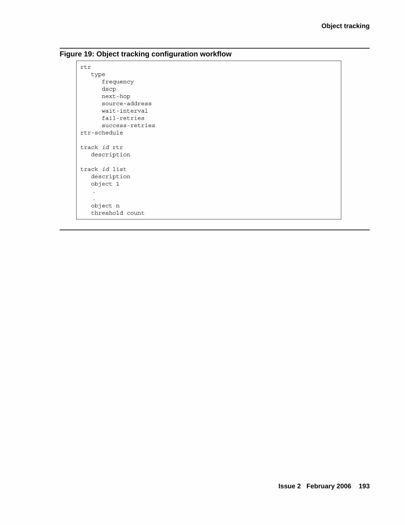
Object tracking
Issue 2 February 2006 193
Figure 19: Object tracking configuration workflowrtr type frequency dscp next-hop source-address wait-interval fail-retries success-retriesrtr-schedule
track id rtr description
track id list description object 1
.
. object n threshold count
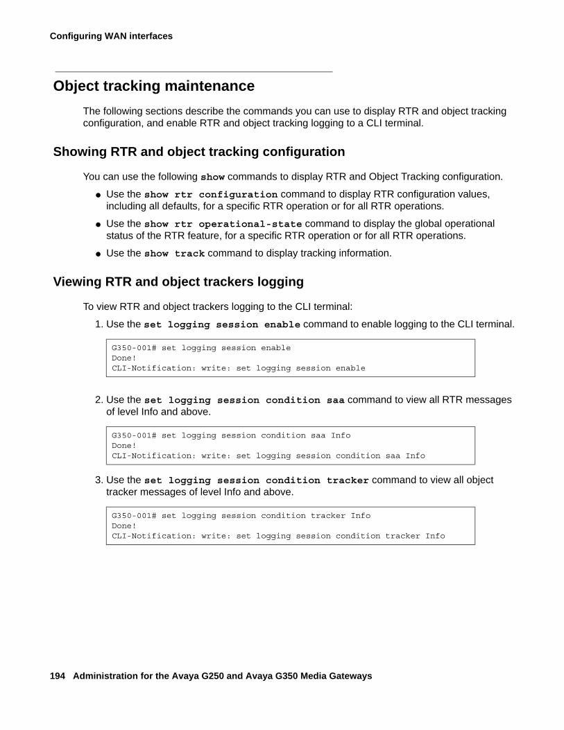
Configuring WAN interfaces
194 Administration for the Avaya G250 and Avaya G350 Media Gateways
Object tracking maintenanceThe following sections describe the commands you can use to display RTR and object tracking configuration, and enable RTR and object tracking logging to a CLI terminal.
Showing RTR and object tracking configuration
You can use the following show commands to display RTR and Object Tracking configuration.
● Use the show rtr configuration command to display RTR configuration values, including all defaults, for a specific RTR operation or for all RTR operations.
● Use the show rtr operational-state command to display the global operational status of the RTR feature, for a specific RTR operation or for all RTR operations.
● Use the show track command to display tracking information.
Viewing RTR and object trackers logging
To view RTR and object trackers logging to the CLI terminal:
1. Use the set logging session enable command to enable logging to the CLI terminal.
2. Use the set logging session condition saa command to view all RTR messages of level Info and above.
3. Use the set logging session condition tracker command to view all object tracker messages of level Info and above.
G350-001# set logging session enableDone!CLI-Notification: write: set logging session enable
G350-001# set logging session condition saa InfoDone!CLI-Notification: write: set logging session condition saa Info
G350-001# set logging session condition tracker InfoDone!CLI-Notification: write: set logging session condition tracker Info
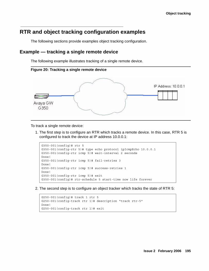
Object tracking
Issue 2 February 2006 195
RTR and object tracking configuration examplesThe following sections provide examples object tracking configuration.
Example — tracking a single remote device
The following example illustrates tracking of a single remote device.
Figure 20: Tracking a single remote device
To track a single remote device:
1. The first step is to configure an RTR which tracks a remote device. In this case, RTR 5 is configured to track the device at IP address 10.0.0.1:
2. The second step is to configure an object tracker which tracks the state of RTR 5:
G350-001(config)# rtr 5G350-001(config-rtr 5)# type echo protocol ipIcmpEcho 10.0.0.1G350-001(config-rtr icmp 5)# wait-interval 2 secondsDone!G350-001(config-rtr icmp 5)# fail-retries 3Done!G350-001(config-rtr icmp 5)# success-retries 1Done!G350-001(config-rtr icmp 5)# exitG350-001(config)# rtr-schedule 5 start-time now life forever
G250-001(config)# track 1 rtr 5G250-001(config-track rtr 1)# description "track rtr-5"Done!G250-001(config-track rtr 1)# exit
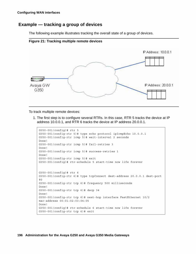
Configuring WAN interfaces
196 Administration for the Avaya G250 and Avaya G350 Media Gateways
Example — tracking a group of devices
The following example illustrates tracking the overall state of a group of devices.
Figure 21: Tracking multiple remote devices
To track multiple remote devices:
1. The first step is to configure several RTRs. In this case, RTR 5 tracks the device at IP address 10.0.0.1, and RTR 6 tracks the device at IP address 20.0.0.1.
G350-001(config)# rtr 5G350-001(config-rtr 5)# type echo protocol ipIcmpEcho 10.0.0.1G350-001(config-rtr icmp 5)# wait-interval 2 secondsDone!G350-001(config-rtr icmp 5)# fail-retries 3Done!G350-001(config-rtr icmp 5)# success-retries 1Done!G350-001(config-rtr icmp 5)# exitG350-001(config)# rtr-schedule 5 start-time now life forever
G350-001(config)# rtr 6G350-001(config-rtr 6)# type tcpConnect dest-address 20.0.0.1 dest-port 80G350-001(config-rtr tcp 6)# frequency 500 millisecondsDone!G350-001(config-rtr tcp 6)# dscp 34Done!G350-001(config-rtr tcp 6)# next-hop interface FastEthernet 10/2 mac-address 00:01:02:03:04:05Done!G350-001(config)# rtr-schedule 6 start-time now life foreverG350-001(config-rtr tcp 6)# exit
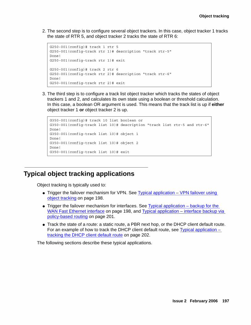
Object tracking
Issue 2 February 2006 197
2. The second step is to configure several object trackers. In this case, object tracker 1 tracks the state of RTR 5, and object tracker 2 tracks the state of RTR 6:
3. The third step is to configure a track list object tracker which tracks the states of object trackers 1 and 2, and calculates its own state using a boolean or threshold calculation. In this case, a boolean OR argument is used. This means that the track list is up if either object tracker 1 or object tracker 2 is up.
Typical object tracking applications Object tracking is typically used to:
● Trigger the failover mechanism for VPN. See Typical application – VPN failover using object tracking on page 198.
● Trigger the failover mechanism for interfaces. See Typical application – backup for the WAN Fast Ethernet interface on page 198, and Typical application – interface backup via policy-based routing on page 201.
● Track the state of a route: a static route, a PBR next hop, or the DHCP client default route. For an example of how to track the DHCP client default route, see Typical application – tracking the DHCP client default route on page 202.
The following sections describe these typical applications.
G250-001(config)# track 1 rtr 5G250-001(config-track rtr 1)# description "track rtr-5"Done!G250-001(config-track rtr 1)# exit
G250-001(config)# track 2 rtr 6G250-001(config-track rtr 2)# description "track rtr-6"Done!G250-001(config-track rtr 2)# exit
G350-001(config)# track 10 list boolean orG350-001(config-track list 10)# description "track list rtr-5 and rtr-6"Done!G350-001(config-track list 10)# object 1Done!G350-001(config-track list 10)# object 2Done!G350-001(config-track list 10)# exit
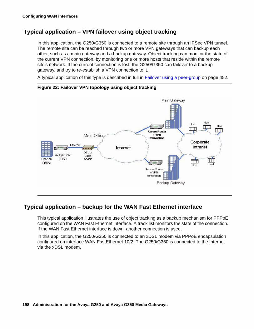
Configuring WAN interfaces
198 Administration for the Avaya G250 and Avaya G350 Media Gateways
Typical application – VPN failover using object tracking
In this application, the G250/G350 is connected to a remote site through an IPSec VPN tunnel. The remote site can be reached through two or more VPN gateways that can backup each other, such as a main gateway and a backup gateway. Object tracking can monitor the state of the current VPN connection, by monitoring one or more hosts that reside within the remote site's network. If the current connection is lost, the G250/G350 can failover to a backup gateway, and try to re-establish a VPN connection to it.A typical application of this type is described in full in Failover using a peer-group on page 452.
Figure 22: Failover VPN topology using object tracking
Typical application – backup for the WAN Fast Ethernet interface
This typical application illustrates the use of object tracking as a backup mechanism for PPPoE configured on the WAN Fast Ethernet interface. A track list monitors the state of the connection. If the WAN Fast Ethernet interface is down, another connection is used.In this application, the G250/G350 is connected to an xDSL modem via PPPoE encapsulation configured on interface WAN FastEthernet 10/2. The G250/G350 is connected to the Internet via the xDSL modem.
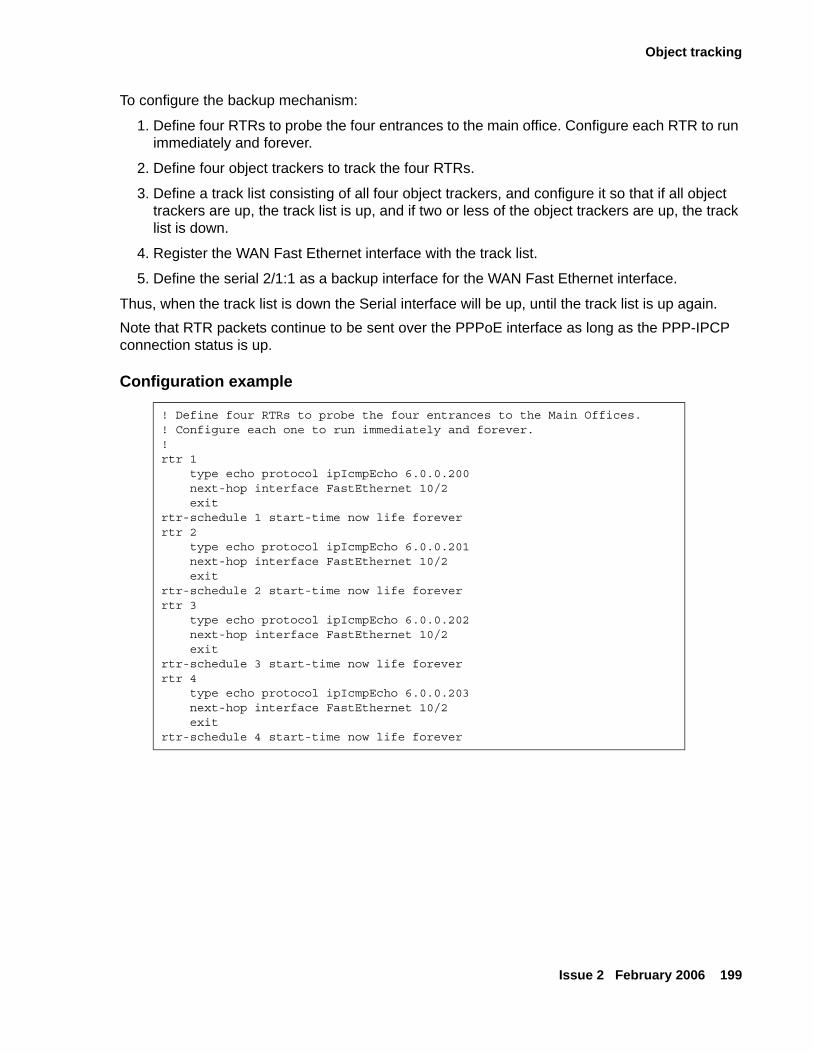
Object tracking
Issue 2 February 2006 199
To configure the backup mechanism:
1. Define four RTRs to probe the four entrances to the main office. Configure each RTR to run immediately and forever.
2. Define four object trackers to track the four RTRs.
3. Define a track list consisting of all four object trackers, and configure it so that if all object trackers are up, the track list is up, and if two or less of the object trackers are up, the track list is down.
4. Register the WAN Fast Ethernet interface with the track list.
5. Define the serial 2/1:1 as a backup interface for the WAN Fast Ethernet interface.
Thus, when the track list is down the Serial interface will be up, until the track list is up again. Note that RTR packets continue to be sent over the PPPoE interface as long as the PPP-IPCP connection status is up.
Configuration example
! Define four RTRs to probe the four entrances to the Main Offices. ! Configure each one to run immediately and forever.!rtr 1 type echo protocol ipIcmpEcho 6.0.0.200 next-hop interface FastEthernet 10/2 exitrtr-schedule 1 start-time now life foreverrtr 2 type echo protocol ipIcmpEcho 6.0.0.201 next-hop interface FastEthernet 10/2 exitrtr-schedule 2 start-time now life foreverrtr 3 type echo protocol ipIcmpEcho 6.0.0.202 next-hop interface FastEthernet 10/2 exitrtr-schedule 3 start-time now life foreverrtr 4 type echo protocol ipIcmpEcho 6.0.0.203 next-hop interface FastEthernet 10/2 exitrtr-schedule 4 start-time now life forever
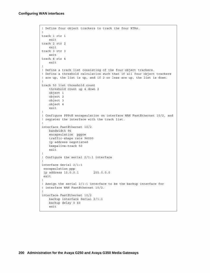
Configuring WAN interfaces
200 Administration for the Avaya G250 and Avaya G350 Media Gateways
! Define four object trackers to track the four RTRs.!track 1 rtr 1 exittrack 2 rtr 2 exittrack 3 rtr 3 exittrack 4 rtr 4 exit!! Define a track list consisting of the four object trackers.! Define a threshold calculation such that if all four object trackers! are up, the list is up, and if 2 or less are up, the list is down.!track 50 list threshold count threshold count up 4 down 2 object 1 object 2 object 3 object 4 exit! ! Configure PPPoE encapsulation on interface WAN FastEthernet 10/2, and! register the interface with the track list.!interface FastEthernet 10/2 bandwidth 96 encapsulation pppoe traffic-shape rate 96000 ip address negotiated keepalive-track 50 exit!! Configure the serial 2/1:1 interface!interface Serial 2/1:1 encapsulation ppp ip address 10.0.0.1 255.0.0.0 exit!! Assign the serial 2/1:1 interface to be the backup interface for! interface WAN FastEthernet 10/2.!interface FastEthernet 10/2 backup interface Serial 2/1:1 backup delay 0 60 exit
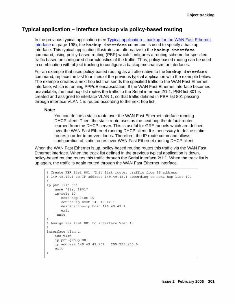
Object tracking
Issue 2 February 2006 201
Typical application – interface backup via policy-based routing
In the previous typical application (see Typical application – backup for the WAN Fast Ethernet interface on page 198), the backup interface command is used to specify a backup interface. This typical application illustrates an alternative to the backup interface command, using policy-based routing (PBR) which configures a routing scheme for specified traffic based on configured characteristics of the traffic. Thus, policy-based routing can be used in combination with object tracking to configure a backup mechanism for interfaces. For an example that uses policy-based routing as an alternative to the backup interface command, replace the last four lines of the previous typical application with the example below. The example creates a next hop list that sends the specified traffic to the WAN Fast Ethernet interface, which is running PPPoE encapsulation. If the WAN Fast Ethernet interface becomes unavailable, the next hop list routes the traffic to the Serial interface 2/1:1. PBR list 801 is created and assigned to interface VLAN 1, so that traffic defined in PBR list 801 passing through interface VLAN 1 is routed according to the next hop list.
Note:Note: You can define a static route over the WAN Fast Ethernet interface running
DHCP client. Then, the static route uses as the next hop the default router learned from the DHCP server. This is useful for GRE tunnels which are defined over the WAN Fast Ethernet running DHCP client. It is necessary to define static routes in order to prevent loops. Therefore, the IP route command allows configuration of static routes over WAN Fast Ethernet running DHCP client.
When the WAN Fast Ethernet is up, policy-based routing routes this traffic via the WAN Fast Ethernet interface. When the track list defined in the previous typical application is down, policy-based routing routes this traffic through the Serial interface 2/1:1. When the track list is up again, the traffic is again routed through the WAN Fast Ethernet interface.
! Create PBR list 801. This list routes traffic from IP address ! 149.49.42.1 to IP address 149.49.43.1 according to next hop list 10.!ip pbr-list 801 name "list #801" ip-rule 10 next-hop list 10 source-ip host 149.49.42.1 destination-ip host 149.49.43.1 exit exit!! Assign PBR list 801 to interface Vlan 1.!interface Vlan 1 icc-vlan ip pbr-group 801 ip address 149.49.42.254 255.255.255.0 exit!
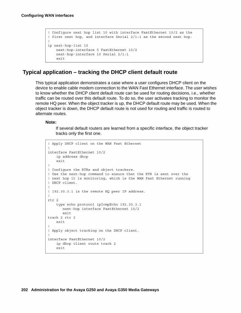
Configuring WAN interfaces
202 Administration for the Avaya G250 and Avaya G350 Media Gateways
Typical application – tracking the DHCP client default route
This typical application demonstrates a case where a user configures DHCP client on the device to enable cable modem connection to the WAN Fast Ethernet interface. The user wishes to know whether the DHCP client default route can be used for routing decisions, i.e., whether traffic can be routed over this default route. To do so, the user activates tracking to monitor the remote HQ peer. When the object tracker is up, the DHCP default route may be used. When the object tracker is down, the DHCP default route is not used for routing and traffic is routed to alternate routes.
Note:Note: If several default routers are learned from a specific interface, the object tracker
tracks only the first one.
! Configure next hop list 10 with interface FastEthernet 10/2 as the! first next hop, and interface Serial 2/1:1 as the second next hop.!ip next-hop-list 10 next-hop-interface 5 FastEthernet 10/2 next-hop-interface 10 Serial 2/1:1 exit
! Apply DHCP client on the WAN Fast Ethernet !interface FastEthernet 10/2 ip address dhcp
exit!! Configure the RTRs and object trackers.! Use the next-hop command to ensure that the RTR is sent over the ! next hop it is monitoring, which is the WAN Fast Ethernet running ! DHCP client.!! 192.30.3.1 is the remote HQ peer IP address.!rtr 2 type echo protocol ipIcmpEcho 192.30.3.1 next-hop interface FastEthernet 10/2
exittrack 2 rtr 2
exit!! Apply object tracking on the DHCP client.! interface FastEthernet 10/2 ip dhcp client route track 2
exit
Frame relay encapsulation features
Issue 2 February 2006 203
Frame relay encapsulation featuresThe Avaya G250/G350 Media Gateway supports the following frame relay encapsulation features:
● Frame Relay Traffic Shaping and FRF.12 Fragmentation
● Priority DLCI
Note:Note: The terms PVC (Permanent Virtual Circuit) and DLCI (Data Link Connection
Identifier) describe the same entity and are interchangeable.
To improve voice quality using RTP, see Configuring header compression on page 134.
Frame Relay Traffic Shaping and FRF.12 FragmentationFrame Relay Traffic shaping regulates the outgoing traffic rate on a per-DLCI basis. Each DLCI maintains a weighted fair VoIP queue scheduler to buffer the packets.
FRF.12 Fragmentation allows for link fragmentation and interleaving (LFI), which reduces the serialization delay on narrow bandwidth PVCs. This is required for VoIP traffic.
You can configure the traffic shaping and fragmentation parameters within map classes. A map class is comprised of the following parameters:
● CIR — default 56,000 bps
● Committed Burst (BC) size — default 7,000 bps
● Excess Burst (BE) size — default 0 bps
● Fragmentation — fragment size, in bytes. The default is No Fragmentation.
You can configure up to 128 different map classes using different combinations of traffic shaping parameters. You then apply these map classes to a PVC.
Note:Note: For a Priority DLCI group you must configure the Primary VC before associating
a DLCI map class to the Priority DLCI group VCs. Removing the Primary VC after associating a DLCI map class to the Priority LCI group VCs, removes their map class configuration.
You can enable traffic shaping on a frame relay interface using the frame-relay traffic-shaping command. After you enable traffic shaping, a default map class is applied to all currently configured PVCs.
Configuring WAN interfaces
204 Administration for the Avaya G250 and Avaya G350 Media Gateways
Priority DLCITo implement new priority mechanisms, ISPs rely on new classes of service. Traffic types and users are divided into these classes and treated differently during peak periods. A premium, or first class user or traffic stream receives higher priority than a general user. This rating system ensures that the critical Internet user maintains peak performance. It also provides a means for ISPs to enhance the cost structure of network operations.
The G250/G350 supports class-based traffic assignment (priority DLCI). Priority DLCI is a means for implementing QoS on frame relay circuits. The G250/G350 separates traffic with different QoS levels to up to four different VCs on the same frame relay sub-interface. This feature enables you to assign unique Permanent VCs (PVC) for VoIP and non-VoIP traffic. You can set and adjust the priority using policy. For more information, see Configuring policy on page 463.
Configure Priority DLCI using the frame-relay priority-dlci-group command in the serial sub-interface context. Specify the DLCIs in this command from the highest to lowest priority. If you specify less than four DLCIs, the last DLCI specified is automatically used for the missing priorities.
When using Priority DLCI, the primary DLCI is used to determine the state of the sub frame relay interface. When the primary DLCI is up, the sub frame relay interface is up. When the primary DLCI is down, the sub frame relay interface is down. When using Priority DLCI, it is therefore recommended to verify that the primary DLCI is set as the High Priority DLCI in the Priority DLCI group.
On the Avaya G250/G350 Media Gateway, OSPF is mapped by default to the High Priority DLCI. For better network reliability, it is recommended to verify that the same configuration exists on the other side of the frame relay connection.
If one of the Priority DLCIs is down, its traffic is dropped.
Map the PVC control protocol on the routers at all ends of a multi-VC point-to-point link. Map this VC to the highest priority DLCI.
WAN configuration exampleThis section contains an example that illustrates a common PPP VoIP configuration between two sites connected over a WAN.
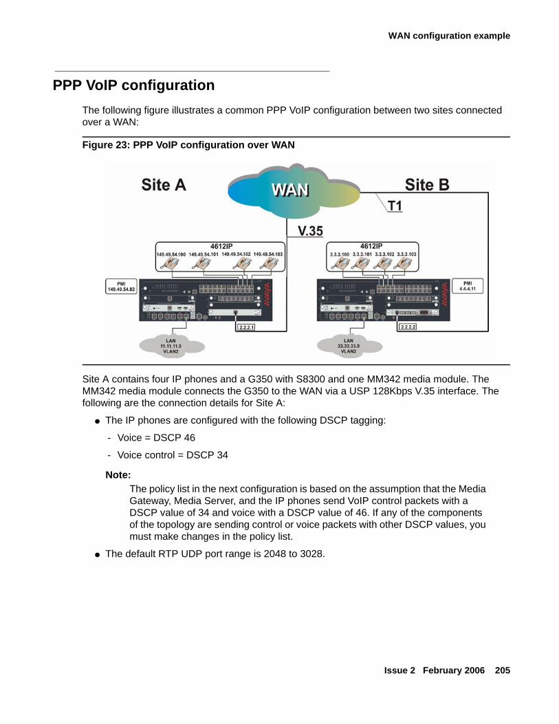
WAN configuration example
Issue 2 February 2006 205
PPP VoIP configurationThe following figure illustrates a common PPP VoIP configuration between two sites connected over a WAN:
Figure 23: PPP VoIP configuration over WAN
Site A contains four IP phones and a G350 with S8300 and one MM342 media module. The MM342 media module connects the G350 to the WAN via a USP 128Kbps V.35 interface. The following are the connection details for Site A:
● The IP phones are configured with the following DSCP tagging:
- Voice = DSCP 46
- Voice control = DSCP 34
Note:Note: The policy list in the next configuration is based on the assumption that the Media
Gateway, Media Server, and the IP phones send VoIP control packets with a DSCP value of 34 and voice with a DSCP value of 46. If any of the components of the topology are sending control or voice packets with other DSCP values, you must make changes in the policy list.
● The default RTP UDP port range is 2048 to 3028.
Configuring WAN interfaces
206 Administration for the Avaya G250 and Avaya G350 Media Gateways
● Network IPs (24 bit subnet masks):
- IP phones - 149.49.54.0 (VLAN 1)
- Data - 11.11.11.0 (VLAN 2)
- Serial - 2.2.2.1
- S8300 - 149.49.54.81
- G350 PMI - 149.49.54.82
Site B contains four IP phones and a G350 with S8300 and one MM340 media module. The MM340 media module connects the G350 to the WAN via a two-timeslot (128Kbps) T1 interface. The following are the connection details for Site B:
● IP phone are configured with DSCP tagging:
- Voice = DSCP 46
- Voice control = DSCP 34
● The default RTP UDP port range is 2048 to 3028.
● Network IPs (24 bit subnet masks):
- IP phones - 3.3.3.0 (VLAN 1)
- Data - 33.33.33.0 (VLAN 2)
- Serial - 2.2.2.2
- S8300 - 4.4.4.10
- G350 PMI - 4.4.4.11
Configuration Example for Site A
The following is the procedure for configuring PPP VoIP on the G350 at Site A. Commands with footnotes are described at the end of the configuration procedure.
● Loopback and PMI interfaces configuration:
G350-001# interface Loopback 1G350-001(if:Loopback 1)# ip address 149.49.54.82 24Done!G350-001(if:Loopback 1)# pmiThe Primary management interface has changed. Please copy the running configuration to the start-up configuration file, and reset the device.G350-001(if:Loopback 1)# exitG350-001# copy running-config startup-configG350-001# reset
WAN configuration example
Issue 2 February 2006 207
● VLAN interface configuration:
● Serial interface configuration:
Note:Note: Some LAN data applications do not support fragmented packets. In this case, do
not change the MTU from its default of 1500.
● VoIP configuration:
● Static routes configuration:
* Description of footnoted commands (also applies to identical stages in configuring Site B):
(1) At this stage you apply Priority 7 to Voice Control traffic.
(2) At this stage you apply Priority 6 to RTP traffic.
(3) At this stage you apply maximum trust between 802.1p priority and DSCP.
(4) At this stage the number of connections (20) depends on the number of phones.
(5) At this stage you are matching the RTP port range to that of the G350.
(6) At this stage the default queue size is 6, and since RTP is enabled you can double the VoIP queue size.
G350-001# interface Vlan 1G350-001(if:Vlan 1)# ip address 149.49.54.24Done!G350-001(if:Vlan 1)# exitG350-001# interface Vlan 2G350-001(if:Vlan 2)# ip address 11.11.11.1 24Done!G350-001(if:Vlan 2)# exit
G350-001# interface Serial 5/1G350-001(if:Serial 5/1)# ip address 2.2.2.1 24G350-001(if:Serial 5/1)# mtu 300
G350-001(if:Serial 5/1)# bandwidth 128
G350-001(if:Serial 5/1)# ip rtp header-compressionG350-001(if:Serial 5/1)# ip rtp compression-connections 20 (4)G350-001(if:Serial 5/1)# ip rtp port-range 2048 3028 (5)G350-001(if:Serial 5/1)# exit
G350-001# ip default-gateway 5/1
Configuring WAN interfaces
208 Administration for the Avaya G250 and Avaya G350 Media Gateways
Configuration Example for Site B
The following is the procedure for configuring PPP VoIP on the G350 at Site B.
● Loopback and PMI interfaces configuration:
● VLAN interface configuration:
● Serial interface configuration:
Note:Note: Some LAN data applications do not support fragmented packets. In this case, do
not change the MTU from its default of 1500.
● VoIP configuration:
● Static routes configuration:
G350-001# interface Loopback 1G350-001(if:Loopback1)# ip address 4.4.4.11 32Done!G350-001(if:Loopback 1)# pmiThe Primary management interface has changed. Please copy the running configuration to the start-up configuration file, and reset the device.G350-001(if:Loopback1)# exitG350-001# copy running-config startup-configG350-001# reset
G350-001# interface Vlan 1G350-001(if:Vlan 1)# ip address 3.3.3.1 24G350-001(if:Vlan 1)# exitG350-001# interface Vlan 2G350-001(if:Vlan 1:2)# ip address 33.33.33.1 24G350-001(if:Vlan 1:2)# exit
G350-001# controller t1 5/1G350-001(controller:5/1)# channel-group 1 timeslots 1-2 speed 64G350-001(controller:5/1)# exitG350-001# interface Serial 5/1:1G350-001(if:Serial 5/1:1)# ip address 2.2.2.2 24G350-001(if:Serial 5/1:1)# mtu 300
G350-001(if:Serial 5/1:1)# ip rtp header-compressionG350-001(if:Serial 5/1:1)# ip rtp compression-connections 20G350-001(if:Serial 5/1:1)# ip rtp port-range 2048 3028G350-001(if:Serial 5/1:1)# exit
G350-001# ip route 1.1.1.0 24 serial 5/1:1G350-001# ip route 11.11.11.0 24 serial 5/1:1

Issue 2 February 2006 209
Chapter 11: Configuring PoE
This chapter provides information about Power over Ethernet (PoE) on the G250/G350, and contains the following sections:
● PoE overview — an overview of PoE on the G250 and G350
● PoE configuration CLI commands — a list and descriptions of CLI commands for PoE configuration
● PoE configuration examples — examples of PoE configurations
PoE overviewThis section provides an overview of Power over Ethernet (PoE) on the G250/G350, and includes the following topics:
● Introduction to PoE on the G250 and G350
● Load detection
● Powering devices
Introduction to PoE on the G250 and G350The Avaya G350 MM314 and MM316 PoE media modules provide Inline DC power over the signal pairs, in addition to switched Ethernet, on the existing LAN infrastructure for devices such as IP telephones and Wireless LAN access points. This allows you to deploy devices in the network that require power without installing standard power cables. The G350 MM314 and MM316 enable you to configure a power consumption usage threshold, as well as to generate traps when this threshold is crossed.
The MM314 and MM316 PoE media modules provide power over standard Category 3 and Category 5 cables. The MM314 and MM316 PoE media modules are designed to comply with the IEEE 802.3af standard.
The G250 provides the same PoE functionality as the MM314 and MM316 PoE media modules, except that the G250 provides PoE functionality through the gateway itself to the eight Ethernet LAN PoE ports located on the G250’s front panel.
Note:Note: The G250-DCP model does not support PoE.
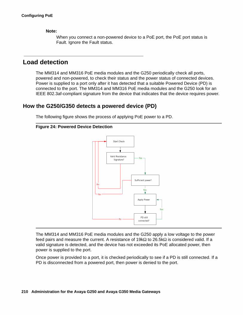
Configuring PoE
210 Administration for the Avaya G250 and Avaya G350 Media Gateways
Note:Note: When you connect a non-powered device to a PoE port, the PoE port status is
Fault. Ignore the Fault status.
Load detectionThe MM314 and MM316 PoE media modules and the G250 periodically check all ports, powered and non-powered, to check their status and the power status of connected devices. Power is supplied to a port only after it has detected that a suitable Powered Device (PD) is connected to the port. The MM314 and MM316 PoE media modules and the G250 look for an IEEE 802.3af-compliant signature from the device that indicates that the device requires power.
How the G250/G350 detects a powered device (PD)
The following figure shows the process of applying PoE power to a PD.
Figure 24: Powered Device Detection
The MM314 and MM316 PoE media modules and the G250 apply a low voltage to the power feed pairs and measure the current. A resistance of 19kΩ to 26.5kΩ is considered valid. If a valid signature is detected, and the device has not exceeded its PoE allocated power, then power is supplied to the port.
Once power is provided to a port, it is checked periodically to see if a PD is still connected. If a PD is disconnected from a powered port, then power is denied to the port.
Start Check
Valid ResistanceSignature?
Apply Power
Yes
No
PD stillconnected?
No
Yes
Sufficient power?
Yes
No
PoE overview
Issue 2 February 2006 211
Plug and Play Operation
You can add and remove PDs without manually reconfiguring the switch, since it performs a periodic automatic load detection scan on non-powered ports.
● If a PD that fits the above criteria is detected on a non-powered port, then power is applied to the port.
● If a PD is removed from a port, then power is denied to that port. The disconnected port is then scanned as well.
In addition, if the PoE module in the G350 is removed and replaced with a module of the same type, the port power configuration of the module is retained.
Powering devicesThe Avaya G350 MM314 and MM316 media modules have their own power supplies. For the MM314 media module, a full 335 W of power is available for PDs. For the MM316 media module, 435 W of power is available for PDs. Each port can supply up to 19.5 W by default. If a PD tries to draw more than the maximum allowed power per port, power is denied.
The G250 has 92 W of power available for PDs. Each port can supply up to 18.8 W by default. If a PD tries to draw more than the maximum allowed power per port, power is denied.
Since the power available may not be enough for driving PDs on all the ports simultaneously, a priority mechanism exists. The priority mechanism determines the order in which ports are powered after the switch is booted.
There are three user-configurable PoE priority levels:
● Low
● High
● Critical
The default value for all ports is Low.
Power is automatically applied to PDs according to their priority when the power budget increases. If the power budget is exceeded, power is not provided to a new PD when you attach it, even if you define its priority as High or Critical.
Note:Note: The order in which ports are powered within the same priority group is not
sequential.
Configuring PoE
212 Administration for the Avaya G250 and Avaya G350 Media Gateways
PoE configuration CLI commandsUse the following commands to configure PoE on the G250, or the G350’s MM314 or MM316 PoE media module:
● Use the set port powerinline command to enable or disable load detection on a port.
● Use the set port powerinline type command to configure the connected PD type.
● Use the set port powerinline priority to configure the PoE priority level over a port.
● Use the set powerinline trap enable to configure PoE traps and the consumption usage threshold value.
● Use the show powerinline command to display Power over Ethernet (PoE) information.
Note:Note: If another PoE-enabled device (such as a P333T-PWR switch) is connected to a
port, the show powerinline command may incorrectly show the port power status as Delivering Power. To disable inline power for a port connected to a P333T-PWR, use the command set port powerinline disable.
PoE configuration examplesThis section provides PoE configuration examples.
The following example enables PoE on a G250 port:
The following example enables PoE on a G350 port:
The following example disables PoE on a G250 port:
G250-001(super)# set port powerinline 10/4 enableLoad detection process on port 10/4 is enabled.
G350-001(super)# set port powerinline 6/12 enableLoad detection process on port 6/12 is enabled.
G250-001(super)# set port powerinline 10/5 disableLoad detection process on port 10/5 is disabled.
PoE configuration examples
Issue 2 February 2006 213
The following example disables PoE on a G350 port:
The following example configures PoE priority on a G250 port:
The following example configures PoE priority on a G350 port:
The following example displays PoE information for the G350:
G350-001(super)# set port powerinline 6/12 disableLoad detection process on port 6/12 is disabled.
G250-001(super)# set port powerinline priority 10/3 highPowering priority on port 10/3 was set to High.
G350-001(super)# set port powerinline priority 6/14 highPowering priority on port 6/14 was set to High.
G350-001(super)# show powerinlineActual powerinline power consumption is 4 W.Powerinline power consumption trap threshold is 207(99%) Watts.Powerline traps are enabledPort Inline Powering PD Operational Priority Type Status------ ------------------ --------- --------6/1 Searching Low telephone6/2 Searching Low telephone6/3 Searching Low telephone6/4 Searching Low telephone6/5 Searching Low telephone6/6 Searching Low telephone6/7 Searching Low telephone6/8 Searching Low telephone6/9 Searching Low telephone6/10 Searching Low telephone6/11 Searching Low telephone6/12 Disabled Low telephone6/13 Searching Low telephone6/14 Searching High telephone6/15 Searching Low telephone6/16 Searching Low telephone6/17 Fault Low telephone6/18 Fault Low telephone6/19 Searching Low telephone6/20 Searching Low telephone6/21 Searching Low telephone6/22 Fault Low telephone6/23 Delivering Power Low telephone

Configuring PoE
214 Administration for the Avaya G250 and Avaya G350 Media Gateways
The following example displays PoE information for the G250:
G250-003(super)# show powerinlineActual powerinline power consumption is 4 W.Powerinline power consumption trap threshold is 90 (98%) Watts.Powerline traps are enabledPort Inline Powering PD Operational Priority Type Status------ ------------------ --------- --------10/3 Searching Low telephone10/4 Searching Low telephone10/5 Searching Low telephone10/6 Searching Low telephone10/7 Delivering Power Low telephone10/8 Searching Low telephone10/9 Searching Low telephone10/10 Searching Low telephone
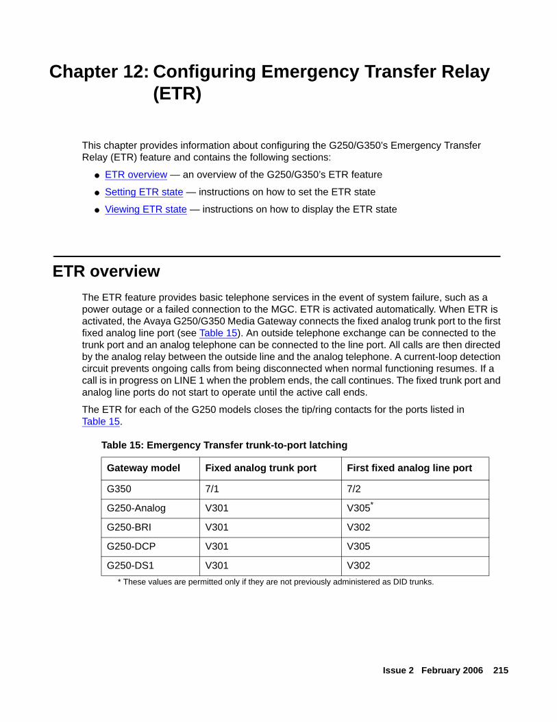
Issue 2 February 2006 215
Chapter 12: Configuring Emergency Transfer Relay (ETR)
This chapter provides information about configuring the G250/G350’s Emergency Transfer Relay (ETR) feature and contains the following sections:
● ETR overview — an overview of the G250/G350’s ETR feature
● Setting ETR state — instructions on how to set the ETR state
● Viewing ETR state — instructions on how to display the ETR state
ETR overviewThe ETR feature provides basic telephone services in the event of system failure, such as a power outage or a failed connection to the MGC. ETR is activated automatically. When ETR is activated, the Avaya G250/G350 Media Gateway connects the fixed analog trunk port to the first fixed analog line port (see Table 15). An outside telephone exchange can be connected to the trunk port and an analog telephone can be connected to the line port. All calls are then directed by the analog relay between the outside line and the analog telephone. A current-loop detection circuit prevents ongoing calls from being disconnected when normal functioning resumes. If a call is in progress on LINE 1 when the problem ends, the call continues. The fixed trunk port and analog line ports do not start to operate until the active call ends.
The ETR for each of the G250 models closes the tip/ring contacts for the ports listed in Table 15.
Table 15: Emergency Transfer trunk-to-port latching
Gateway model Fixed analog trunk port First fixed analog line port
G350 7/1 7/2
G250-Analog V301 V305*
* These values are permitted only if they are not previously administered as DID trunks.
G250-BRI V301 V302
G250-DCP V301 V305
G250-DS1 V301 V302
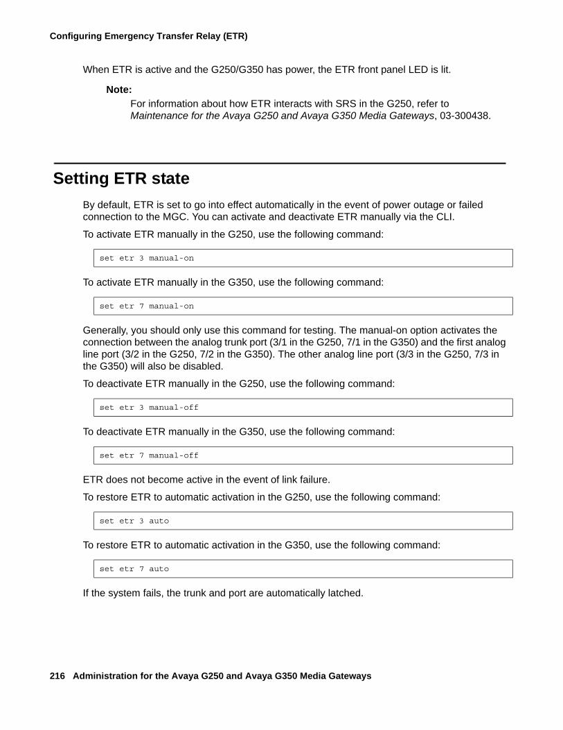
Configuring Emergency Transfer Relay (ETR)
216 Administration for the Avaya G250 and Avaya G350 Media Gateways
When ETR is active and the G250/G350 has power, the ETR front panel LED is lit.
Note:Note: For information about how ETR interacts with SRS in the G250, refer to
Maintenance for the Avaya G250 and Avaya G350 Media Gateways, 03-300438.
Setting ETR stateBy default, ETR is set to go into effect automatically in the event of power outage or failed connection to the MGC. You can activate and deactivate ETR manually via the CLI.
To activate ETR manually in the G250, use the following command:
To activate ETR manually in the G350, use the following command:
Generally, you should only use this command for testing. The manual-on option activates the connection between the analog trunk port (3/1 in the G250, 7/1 in the G350) and the first analog line port (3/2 in the G250, 7/2 in the G350). The other analog line port (3/3 in the G250, 7/3 in the G350) will also be disabled.
To deactivate ETR manually in the G250, use the following command:
To deactivate ETR manually in the G350, use the following command:
ETR does not become active in the event of link failure.
To restore ETR to automatic activation in the G250, use the following command:
To restore ETR to automatic activation in the G350, use the following command:
If the system fails, the trunk and port are automatically latched.
set etr 3 manual-on
set etr 7 manual-on
set etr 3 manual-off
set etr 7 manual-off
set etr 3 auto
set etr 7 auto
Viewing ETR state
Issue 2 February 2006 217
Note:Note: A call in progress will be terminated when ETR is activated wither automatically
or manually. The relay call will be terminated only when ETR is deactivated manually.
Viewing ETR stateYou can use the show etr command to display ETR information. This information includes the following:
● ETR setting (auto, manual-off, or manual-on)
● Module status (in service, out of service, or out of service waiting for off-hook)
● Trunk number of the trunk connected to ETR
● Line number of the line connected to ETR
● Line status (off hook or on hook)

Configuring Emergency Transfer Relay (ETR)
218 Administration for the Avaya G250 and Avaya G350 Media Gateways
Issue 2 February 2006 219
Chapter 13: Configuring SNMP
This chapter provides information about configuring SNMP on the G250/G350 and contains the following sections:
● SNMP configuration overview — an overview of SNMP configuration on G250/G350 devices
● SNMP versions — a description of the SNMP versions supported by the G250/G350
● Configuring SNMP traps — instructions on how to configure SNMP traps on G250/G350 devices
● Configuring SNMP access — instructions on how to configure SNMP access on G250/G350 devices
● Configuring dynamic trap manager — instructions on how to configure dynamic trap manager, a feature that ensures that traps are always sent to the G250/G350’s active MGC
● SNMP configuration examples — examples of SNMP configuration
SNMP configuration overview SNMP uses software entities called managers and agents to manage network devices. The manager monitors and controls all other SNMP-managed devices or network nodes on the network. There must be at least one SNMP Manager in a managed network. The manager is installed on a workstation located on the network.
An agent resides in a managed device or network node. The agent receives instructions from the SNMP Manager, generates reports in response to requests from the SNMP Manager, and sends management information back to the SNMP Manager as events occur. The agent can reside on:
● Routers
● Bridges
● Hubs
● Workstations
● Printers
● Other network devices
Configuring SNMP
220 Administration for the Avaya G250 and Avaya G350 Media Gateways
There are many SNMP management applications, but all these applications perform the same basic task. They allow SNMP managers to communicate with agents to configure, get statistics and information, and receive alerts from network devices. You can use any SNMP-compatible network management system to monitor and control a G250/G350.
There are several ways that the SNMP manager and the agent communicate. The manager can:
● Retrieve a value – a get action.The SNMP manager requests information from the agent, such as the number of users logged on to the agent device or the status of a critical process on that device. The agent gets the value of the requested Management Information Base (MIB) variable and sends the value back to the manager.
● Retrieve the value immediately after the variable you name — a get-next action.The SNMP manager retrieves different instances of MIB variables. The SNMP manager takes the variable you name and then uses a sequential search to find the desired variable.
● Retrieve a number of values — a get-bulk action.The get-bulk operation retrieves the specified number of instances of the requested MIB variable. This minimizes the number of protocol exchanges required to retrieve a large amount of data.
Note:Note: Get-bulk is not supported in SNMPv1.
● Change a configuration on the agent — a set action.The SNMP manager requests the agent to change the value of the MIB variable. For example, you can run a script or an application on a remote device with a set action.
● An agent can send an unsolicited message to the manager at any time if a significant, predetermined event takes place on the agent. This message is called a notification. When a notification condition occurs, the SNMP agent sends an SNMP notification to the device specified as the trap receiver or trap host. The SNMP Administrator configures the trap host, usually the SNMP management station, to perform the action needed when a trap is detected.
Note:Note: For a list of traps and MIBS, see Traps and MIBs on page 559.
SNMP versions
Issue 2 February 2006 221
SNMP versionsThere are currently three versions of SNMP:
● SNMPv1
● SNMPv2c
● SNMPv3
The Avaya G350 Media Gateway supports all three of these versions. The implementation of SNMPv3 on the G350 is backwards compatible. An agent that supports SNMPv3 will also support SNMPv1 and SNMPv2c.
The Avaya G250 Media Gateway supports users for all three of these versions, but only supports the SNMPv3 mechanism for sending traps. Thus, the set snmp trap command is not supported in the G250, although the set snmp trap enable auth|frame-relay command is supported.
SNMPv1SNMPv1 uses community strings to limit access rights. Each SNMP device is assigned to a read community and a write community. To communicate with a device, you must send an SNMP packet with the relevant community name.
By default, if you communicate with a device using only the read community, you are assigned the security name ReadCommN. This security name is mapped to the ReadCommG group by default. This allows you to view the agent’s MIB tree, but you cannot change any of the values in the MIB tree.
If you communicate with a device using the write community, you are assigned the security name WriteCommN. This security name is mapped to the WriteCommG group by default. This allows you to view the agent’s MIB tree and change any of the values in the MIB tree.
Note:Note: If you delete the ReadCommN or WriteCommN users, the ReadCommG or
WriteCommG groups, or the snmpv1WriteView or snmpv1View, you may not be able to access the device using SNMPv1 or SNMPv2c.
In addition, traps are sent to designated trap receivers. Packets with trap information also contain a trap community string.
SNMPv2cSNMPv2c is very similar to SNMPv1. However, SNMPv2c adds support for the get-bulk action and supports a different trap format.
Configuring SNMP
222 Administration for the Avaya G250 and Avaya G350 Media Gateways
SNMPv3SNMPv3 enables the following features over SNMPv1 or v2c:
● User authentication with a user name and password.
● Communication encryption between the Network Management Station (NMS) and the SNMP agent at the application level.
● Access control definition for specific MIB items available on the SNMP agent.
● Notification of specified network events directed toward specified users.
● Definition of roles using access control, each with unique access permissions and authentication and encryption requirements.
The basic components in SNMPv3 access control are users, groups, and views. In addition, SNMPv3 uses an SNMP engine ID to identify SNMP identity. An SNMP engine ID is assigned to each MAC address of each device in the network. Each SNMP engine ID should be unique in the network.
UsersSNMPv3 uses the User-based Security Model (USM) for security, and the View-based Access Control Model (VACM) for access control. USM uses the HMAC-MD5-96 and HMAC-SHA-96 protocols for user authentication, and the CBC-DES56 protocol for encryption or privacy.
An unlimited number of uses can access SNMPv3 at the same time.
SNMP supports three security levels:
● NoAuthNoPriv — This is the lowest level of SNMPv3 security. No Message Authentication Code (MAC) is provided with the message, and no encryption is performed. This method maintains the same security level as SNMPv1, but provides a method for limiting the access rights of the user.
● AuthNoPriv — User authentication is performed based on MD5 or SHA algorithms. The message is sent with an HMAC that is calculated with the user key. The data part is sent unencrypted.
● AuthPriv — User authentication is performed based on MD5 or SHA algorithms. The message is sent in encrypted MAC that is calculated with the user key, and the data part is sent with DES56 encryption using the user key.
Use the snmp-server user command to create a user or to change the parameters of an existing user. This command includes the following parameters:
● Username — A string of up to 32 characters representing the name of the user.
● Groupname — A string of up to 32 characters representing the name of the group with which the user is associated.
SNMP versions
Issue 2 February 2006 223
● SecurityModel — The SNMP version functionality that the user is authorized to use. Possible values are: v1 (SNMPv1), v2c (SNMPv2c), and v3 (SNMPv3).
● Authentication Protocol — The authentication protocol to use. Possible values are: noAuth (no authentication), md5 (HMAC MD5), and sha (HMAC SHA-1).
● Authentication Password — A string of between 8 and 64 characters specifying the user’s authentication password. The authentication password is transformed using the authentication protocol and the SNMP engine ID to create an authentication key.
● Privacy Protocol — The privacy protocol to use. Possible values are: No privacy, DES privacy.
● Privacy Password — A string of between 8 and 64 characters specifying the user’s privacy password.
Use the no form of the snmp-server user command to remove a user and its mapping to a specified group. If you do not specify a group, the no form of the snmp-server user command removes the user from all groups.
GroupsIn SNMPv3, each user is mapped to a group. The group maps its users to defined views. These views define sets of access rights, including read, write, and trap or inform notifications the users can receive.
The group maps its users to views based on the security mode and level with which the user is communicating with the G250/G350. Within a group, the following combinations of security mode and level can be mapped to views:
● SNMPv1 — Anyone with a valid SNMPv1 community name.
● SNMPv2c — Anyone with a valid SNMPv2c community name.
● NoAuthNoPriv — An SNMPv3 user using the NoAuthNoPriv security level.
● AuthNoPriv — An SNMPv3 user using the AuthNoPriv security level.
● AuthPriv — An SNMPv3 user using the AuthPriv security level.
If views are not defined for all security modes and levels, a user can access the highest level view below the user’s security level. For example, if the SNMPv1 and SNMPv2c views are undefined for a group, anyone logging in using SNMPv1 and SNMPv2c cannot access the device. If the NoAuthNoPriv view is not defined for a group, SNMPv3 users with a NoAuthNoPriv security level can access the SNMPv2c view.
To create an SNMPv3 group, the following information must be provided:
● GroupName — A 32-character string representing the name of the group.
● SNMPv1 — The name of the view for anyone communicating with the device via SNMPv1.
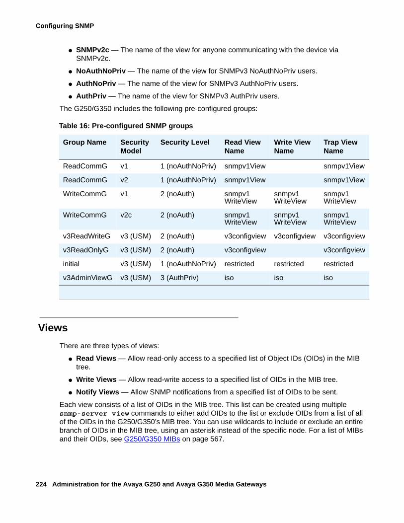
Configuring SNMP
224 Administration for the Avaya G250 and Avaya G350 Media Gateways
● SNMPv2c — The name of the view for anyone communicating with the device via SNMPv2c.
● NoAuthNoPriv — The name of the view for SNMPv3 NoAuthNoPriv users.
● AuthNoPriv — The name of the view for SNMPv3 AuthNoPriv users.
● AuthPriv — The name of the view for SNMPv3 AuthPriv users.
The G250/G350 includes the following pre-configured groups:
ViewsThere are three types of views:
● Read Views — Allow read-only access to a specified list of Object IDs (OIDs) in the MIB tree.
● Write Views — Allow read-write access to a specified list of OIDs in the MIB tree.
● Notify Views — Allow SNMP notifications from a specified list of OIDs to be sent.
Each view consists of a list of OIDs in the MIB tree. This list can be created using multiple snmp-server view commands to either add OIDs to the list or exclude OIDs from a list of all of the OIDs in the G250/G350’s MIB tree. You can use wildcards to include or exclude an entire branch of OIDs in the MIB tree, using an asterisk instead of the specific node. For a list of MIBs and their OIDs, see G250/G350 MIBs on page 567.
Table 16: Pre-configured SNMP groups
Group Name Security Model
Security Level Read View Name
Write View Name
Trap View Name
ReadCommG v1 1 (noAuthNoPriv) snmpv1View snmpv1View
ReadCommG v2 1 (noAuthNoPriv) snmpv1View snmpv1View
WriteCommG v1 2 (noAuth) snmpv1WriteView
snmpv1WriteView
snmpv1WriteView
WriteCommG v2c 2 (noAuth) snmpv1WriteView
snmpv1WriteView
snmpv1WriteView
v3ReadWriteG v3 (USM) 2 (noAuth) v3configview v3configview v3configview
v3ReadOnlyG v3 (USM) 2 (noAuth) v3configview v3configview
initial v3 (USM) 1 (noAuthNoPriv) restricted restricted restricted
v3AdminViewG v3 (USM) 3 (AuthPriv) iso iso iso
Configuring SNMP traps
Issue 2 February 2006 225
To create an SNMPv3 view, the following information must be provided:
● ViewName — A string of up to 32 characters representing the name of the view.
● ViewType — Indicates whether the specified OID is included or excluded from the view.
● OIDs — A list of the OIDs accessible using the view.
Configuring SNMP trapsWhen SNMP traps are enabled on the device, SNMP traps are sent to all IP addresses listed in the trap receivers table. You can add and remove addresses from the trap receivers table. In addition, you can limit the traps sent to specified receivers. You can also enable and disable link up/down traps on specified G250/G350 interfaces. Use the following commands to configure the trap receivers table:
Note:Note: You need an Admin privilege level to use the SNMP commands.
● Use the snmp-server enable notifications command to enable SNMP traps and notifications. Use the no form of this command to disable SNMP traps and notifications.
● Use the set port trap command to enable and disable link-up and link-down notifications and traps.
● Use the set snmp trap enable/disable auth command to enable and disable authentication failure traps for all managers.
● Use the set snmp trap enable frame-relay command to enable frame relay traps for all managers.
● Use the show snmp command to display SNMP information.● Use the snmp-server informs command to configure the SNMPv3 timeout and retries
for notifications.● Use the snmp-server host command to define an SNMPv3 notification host. Use the no form of this command to remove an SNMPv3 notification host and to remove notification filter groups from a specific host. You can define the following parameters with this command:- type — Determines whether to send traps or informs to the recipient. The default is
traps.- version — Determines the SNMP security model (v1, v2c, v3). If the security model is
v1, you must add the v1 community string to use in notifications. If you select v3, you must also specify the authentication method. Options are:● auth — authentication without encryption● noauth — no authentication● priv — authentication with encryption
Configuring SNMP
226 Administration for the Avaya G250 and Avaya G350 Media Gateways
- community string — The v1 community string to use in notifications
- user name — The v3 user name to use in notifications
- udp port — Optional. A keyword and variable that specify which UDP port of the target host to use as the destination UDP port when sending a notification to this manager. The default is 162.
- notification type — The type of traps to be sent. You can choose from the following:
● all — all traps. This is the default.● generic — generic traps● hardware — hardware faults● rmon — RMON rising/falling alarm● dhcp server — DHCP server error, such as a DHCP IP conflict detection or
notification of no IP address left for specific network● dhcp-clients — DHCP client error, such as a DHCP client conflict detection● rtp-stat-faults — RTP statistics: QoS fault/clear traps● rtp-stat-qos — RTP statistics: end-of-call QoS traps● wan — WAN router traps● media-gateway — media gateway traps (equivalent to G700 MGP traps)● security — security traps, such as unAuthAccess, macSecurity, unknownHostCopy,
and accountLockout● config — configuration change notifications● eth-port-faults — Ethernet port fault notifications● sw-redundancy — software redundancy notifications● temperature — temperature warning notifications● cam-change — changes in CAM notifications● 13-events — duplicate IP, VLAN violations● policy — policy change notifications● link-faults — ITC proprietary link down notifications● supply — main and backup power supply notifications
Note:Note: There is no default value for the notification type parameter. Thus, you
must enter a value in order to send traps.
● Use the snmp trap link-status command to enable Link Up and Link Down traps on an interface. You must use this command from an interface context.
● Use the no snmp trap link-status command to disable Link Up and Link Down traps on an interface. You must use this command from an interface context.
Configuring SNMP access
Issue 2 February 2006 227
Configuring SNMP accessUse the following commands to configure SNMP access:
Note:Note: You need an Admin privilege level to use the SNMP commands.
● Use the ip snmp enable command to enable SNMP access to the G250/G350. Use the no form of this command to disable SNMP access to the G250/G350.
● Use the snmp-server community command to enable SNMPv1 access to the G250/G350. Use the no form of this command to disable SNMPv1 access to the G250/G350.
● Use the snmp-server user command to create an SNMPv3 user. Use the no form of this command to remove an SNMPv3 user.
● Use the snmp-server group command to create an SNMPv3 group. Use the no form of this command to remove an SNMPv3 group.
● Use the snmp-server remote-user command to create an SNMPv3 remote user for SNMP notifications. Use the no form of this command to remove an SNMPv3 remote user for SNMP notifications.
● Use the set snmp community command to create or modify an SNMPv1 community.
● Use the snmp-server engineID command to configure the SNMPv3 engine ID. Use the no form of this command to configure the engine ID to its default value. The SNMP engine ID is set automatically by a calculation based on the MAC address of the host device, but you can change the engine ID using this command. If the SNMP engine ID changes, all users other than the default user are invalid and must be redefined.
● Use the snmp-server view command to add or exclude OIDs from a view. Use the no form of this command to delete an SNMPv3 view.
● Use the show snmp view command to display a list of SNMPv3 views.
● Use the show snmp userToGroup command to display a table of SNMPv3 users and the groups to which they are mapped.
● Use the show snmp engineID command to display the SNMPv3 engine ID.
● Use the show snmp group command to display a list of SNMPv3 groups.
● Use the show snmp user command to display a list of SNMPv3 users.
● Use the show snmp command to display a list of SNMP notification receivers.
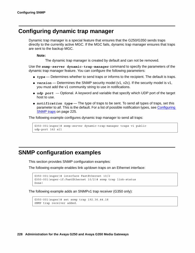
Configuring SNMP
228 Administration for the Avaya G250 and Avaya G350 Media Gateways
Configuring dynamic trap managerDynamic trap manager is a special feature that ensures that the G250/G350 sends traps directly to the currently active MGC. If the MGC fails, dynamic trap manager ensures that traps are sent to the backup MGC.
Note:Note: The dynamic trap manager is created by default and can not be removed.
Use the snmp-server dynamic-trap-manager command to specify the parameters of the dynamic trap manager feature. You can configure the following parameters:
● type — Determines whether to send traps or informs to the recipient. The default is traps.
● version — Determines the SNMP security model (v1, v2c). If the security model is v1, you must add the v1 community string to use in notifications.
● udp port — Optional. A keyword and variable that specify which UDP port of the target host to use.
● notification type — The type of traps to be sent. To send all types of traps, set this parameter to all. This is the default. For a list of possible notification types, see Configuring SNMP traps on page 225.
The following example configures dynamic trap manager to send all traps:
SNMP configuration examplesThis section provides SNMP configuration examples:
The following example enables link up/down traps on an Ethernet interface:
The following example adds an SNMPv1 trap receiver (G350 only):
G350-001(super)# snmp-server dynamic-trap-manager traps v1 publicudp-port 162 all
G350-001(super)# interface FastEthernet 10/2G350-001(super-if:FastEthernet 10/2)# snmp trap link-statusDone!
G350-001(super)# set snmp trap 192.36.44.18SNMP trap receiver added.
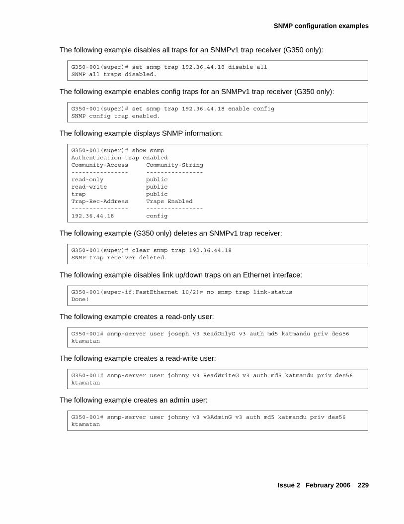
SNMP configuration examples
Issue 2 February 2006 229
The following example disables all traps for an SNMPv1 trap receiver (G350 only):
The following example enables config traps for an SNMPv1 trap receiver (G350 only):
The following example displays SNMP information:
The following example (G350 only) deletes an SNMPv1 trap receiver:
The following example disables link up/down traps on an Ethernet interface:
The following example creates a read-only user:
The following example creates a read-write user:
The following example creates an admin user:
G350-001(super)# set snmp trap 192.36.44.18 disable allSNMP all traps disabled.
G350-001(super)# set snmp trap 192.36.44.18 enable configSNMP config trap enabled.
G350-001(super)# show snmpAuthentication trap enabledCommunity-Access Community-String---------------- ----------------read-only publicread-write publictrap publicTrap-Rec-Address Traps Enabled---------------- ----------------192.36.44.18 config
G350-001(super)# clear snmp trap 192.36.44.18SNMP trap receiver deleted.
G350-001(super-if:FastEthernet 10/2)# no snmp trap link-statusDone!
G350-001# snmp-server user joseph v3 ReadOnlyG v3 auth md5 katmandu priv des56 ktamatan
G350-001# snmp-server user johnny v3 ReadWriteG v3 auth md5 katmandu priv des56 ktamatan
G350-001# snmp-server user johnny v3 v3AdminG v3 auth md5 katmandu priv des56 ktamatan
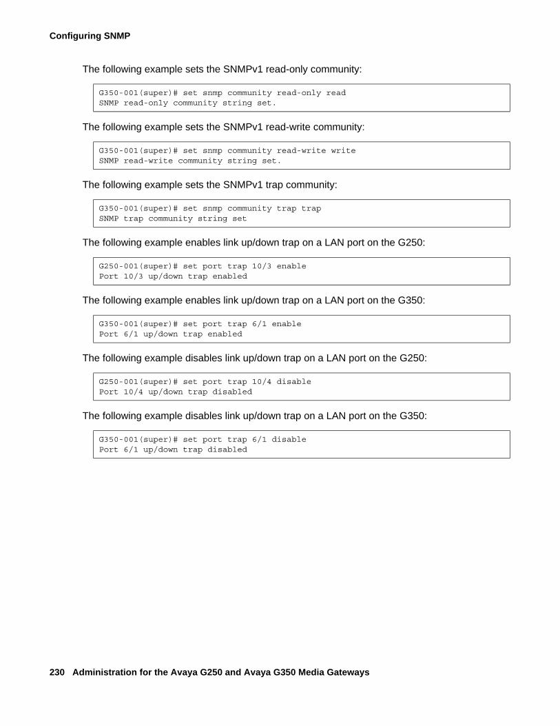
Configuring SNMP
230 Administration for the Avaya G250 and Avaya G350 Media Gateways
The following example sets the SNMPv1 read-only community:
The following example sets the SNMPv1 read-write community:
The following example sets the SNMPv1 trap community:
The following example enables link up/down trap on a LAN port on the G250:
The following example enables link up/down trap on a LAN port on the G350:
The following example disables link up/down trap on a LAN port on the G250:
The following example disables link up/down trap on a LAN port on the G350:
G350-001(super)# set snmp community read-only readSNMP read-only community string set.
G350-001(super)# set snmp community read-write writeSNMP read-write community string set.
G350-001(super)# set snmp community trap trapSNMP trap community string set
G250-001(super)# set port trap 10/3 enablePort 10/3 up/down trap enabled
G350-001(super)# set port trap 6/1 enablePort 6/1 up/down trap enabled
G250-001(super)# set port trap 10/4 disablePort 10/4 up/down trap disabled
G350-001(super)# set port trap 6/1 disablePort 6/1 up/down trap disabled
Issue 2 February 2006 231
Chapter 14: Configuring contact closure
This chapter provides information about configuring the G250/G350’s contact closure feature and contains the following sections:
● Contact closure overview — an overview of contact closure configuration on the G250/G350
● Contact closure hardware configuration — instructions on how to configure the contact closure hardware
● Contact closure software configuration — instructions on how to configure the G250/G350 to use contact closure
● Showing contact closure status — instructions on how to display the contact closure configuration
Contact closure overviewYou can use contact closure to control up to two electrical devices remotely. With contact closure, you can dial feature access codes on a telephone to activate, deactivate, or pulse electrical devices such as electrical door locks. You can also activate and deactivate contact closure using CLI commands. You can only use feature access codes if you configure the Avaya G250/G350 Media Gateway to use a media server with Avaya Communication Manager software. For more information, see Configuring the Media Gateway Controller (MGC) on page 67.
It is recommended that you use an Avaya Partner Contact Closure Adjunct™ for contact closure. For more information, see Overview for the Avaya G250 and Avaya G350 Media Gateways, 03-300435. An Avaya Partner Contact Closure Adjunct contains two relays, one for each electrical device. You can control each relay in any of the following ways:
● When you dial the contact closure open access code, the relay opens (no contact).
● When you dial the contact closure close access code, the relay closes (contact).
● When you dial the contact closure pulse access code, the relay closes (contact) for the pulse duration and then opens (no contact).
● You can control each contact closure relay manually with CLI commands or with Avaya G350 Manager.
Note:Note: Configuration of the feature access code is performed through the Avaya
Communication Manager. For more information, see Administrator Guide for Avaya Communication Manager, 03-300509.
Configuring contact closure
232 Administration for the Avaya G250 and Avaya G350 Media Gateways
Contact closure hardware configurationTo configure your hardware for contact closure:
1. Connect an Avaya Partner Contact Closure Adjunct to the Contact Closure port on the Avaya G250/G350 Media Gateway front panel. The Contact Closure port is labeled CCA on both the G250 and the G350 front panels. Use a telephone cable with standard RJ-11 connectors.
2. A qualified electrician should connect the electrical devices to the relays on the Avaya Partner Contact Closure Adjunct. For information on contact closure specifications, see Overview for the Avaya G250 and Avaya G350 Media Gateways, 03-300435.
Contact closure software configurationYou can specify the following contact closure modes:
To configure the Avaya G250/G350 Media Gateway to activate contact closure when the feature access code is dialed:
1. Enter the set contact-closure admin command. In the following example, the command sets contact closure to work in relay 1 of the Avaya Partner Contact Closure Adjunct when activated by the call controller.
set contact-closure admin 10/1:1 mgc
2. Use the set contact-closure pulse-duration command to set the length of time for the relay to return to normal after the call controller triggers it. In the following example, the command sets relay 2 of the Avaya Partner Contact Closure Adjunct to return to normal 5 seconds after the call controller triggers contact closure in the relay.
set contact-closure pulse-duration 10/1:2 5
Mode Description
mgc The MGC controls contact closure. In mgc mode, the user dials feature access codes to activate and deactivate contact closure.
manual-trigger Activates contact closure for the specified relay.
manual-off Deactivates contact closure for the specified relay.
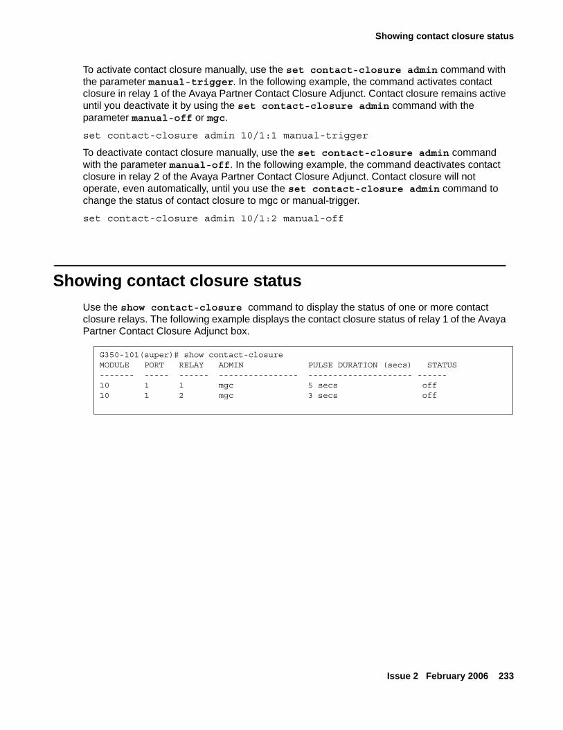
Showing contact closure status
Issue 2 February 2006 233
To activate contact closure manually, use the set contact-closure admin command with the parameter manual-trigger. In the following example, the command activates contact closure in relay 1 of the Avaya Partner Contact Closure Adjunct. Contact closure remains active until you deactivate it by using the set contact-closure admin command with the parameter manual-off or mgc.
set contact-closure admin 10/1:1 manual-trigger
To deactivate contact closure manually, use the set contact-closure admin command with the parameter manual-off. In the following example, the command deactivates contact closure in relay 2 of the Avaya Partner Contact Closure Adjunct. Contact closure will not operate, even automatically, until you use the set contact-closure admin command to change the status of contact closure to mgc or manual-trigger.
set contact-closure admin 10/1:2 manual-off
Showing contact closure statusUse the show contact-closure command to display the status of one or more contact closure relays. The following example displays the contact closure status of relay 1 of the Avaya Partner Contact Closure Adjunct box.
G350-101(super)# show contact-closureMODULE PORT RELAY ADMIN PULSE DURATION (secs) STATUS------- ----- ------ ---------------- --------------------- ------10 1 1 mgc 5 secs off10 1 2 mgc 3 secs off

Configuring contact closure
234 Administration for the Avaya G250 and Avaya G350 Media Gateways

Issue 2 February 2006 235
Chapter 15: Transferring and managing announcement files
The G250/G350 stores announcement files in an internal announcement directory. The G250/G350 supports up to 256 announcement files, totalling up to 15 minutes of audio for announcements and music on hold. The recording, storage, and playing of announcement files are controlled by Avaya CM.
An application called Avaya Voice Announcement Manager (VAM) can be used to centrally manage announcement files for multiple voice systems, including G250/G350 media gateways. VAM is designed to be installed on a customer-provided platform at a remote location. For information about VAM, see Avaya Voice Announcement Manager Reference, 14-300613.
The G250/G350 supports:
● Secure transfer of announcement files to and from Avaya Voice Announcement Manager (VAM) using SCP.
● Simple management operations for the announcement files stored in the announcement directory.
You can perform the following announcement file operations using the CLI:
● Upload an announcement file to a remote SCP server, using the copy announcement-file scp command. Specify the file name of the announcement file in the G250/G350 announcement directory, followed by the IP address of the remote SCP server, and, optionally, a destination file name, including the full path.
● Download an announcement file from a remote SCP server to the G250/G350 announcement directory, using the copy scp announcement-file command. Specify the file name of the announcement file on the remote SCP server, followed by the IP address of the remote SCP server, and, optionally, a destination file name, including the full path.
● Erase an announcement file from the G250/G350 announcement directory, using the erase announcement-file command. Specify the name of the file.
G350-001(super)# copy announcement-file scp local_announcement2.wav 192.168.49.10 c:\remote_announcement2.wav
G350-001(super)# copy scp announcement-file c:\temp\announcement_file1.wav 192.168.49.10
G350-001# erase announcement-file local_announcement1.wav
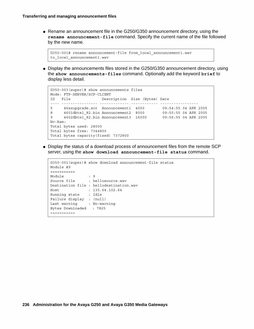
Transferring and managing announcement files
236 Administration for the Avaya G250 and Avaya G350 Media Gateways
● Rename an announcement file in the G250/G350 announcement directory, using the rename announcement-file command. Specify the current name of the file followed by the new name.
● Display the announcements files stored in the G250/G350 announcement directory, using the show announcements-files command. Optionally add the keyword brief to display less detail.
● Display the status of a download process of announcement files from the remote SCP server, using the show download announcement-file status command.
G350-001# rename announcement-file from_local_announcement1.wav to_local_announcement1.wav
G350-003(super)# show announcements filesMode: FTP-SERVER/SCP-CLIENTID File Description Size (Bytes) Date---- ---------------- ------------- ------------ -----------------5 46xxupgrade.scr Announcement1 4000 09:54:55 04 APR 20058 4601dbte1_82.bin Announcement2 8000 09:55:55 04 APR 20059 4602dbte1_82.bin Announcement3 16000 09:56:55 04 APR 2005Nv-Ram:Total bytes used: 28000Total bytes free: 7344800Total bytes capacity(fixed) 7372800
G350-001(super)# show download announcement-file statusModule #9===========Module : 9Source file : hellosource.wavDestination file : hellodestination.wavHost : 135.64.102.64Running state : IdleFailure display : (null)Last warning : No-warningBytes Downloaded : 7825===========
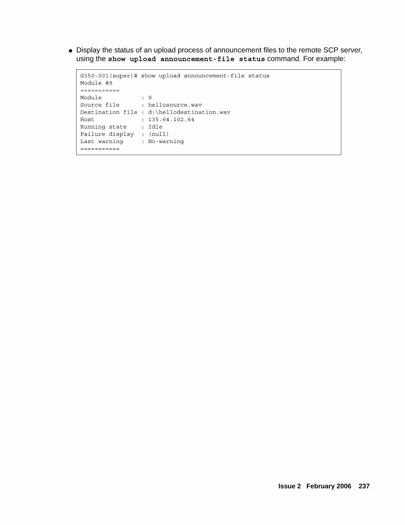
Issue 2 February 2006 237
● Display the status of an upload process of announcement files to the remote SCP server, using the show upload announcement-file status command. For example:
G350-001(super)# show upload announcement-file statusModule #9===========Module : 9Source file : hellosource.wavDestination file : d:\hellodestination.wavHost : 135.64.102.64Running state : IdleFailure display : (null)Last warning : No-warning===========

Transferring and managing announcement files
238 Administration for the Avaya G250 and Avaya G350 Media Gateways
Issue 2 February 2006 239
Chapter 16: Configuring advanced switching
This chapter provides information about configuring advanced switching on the switch ports of the Avaya G250 and G350 Media Gateways. In the G250, the switch ports are the ETH LAN PoE ports located on the front panel. For the G350, switch ports are located on the Avaya MM314 Media Module and the Avaya MM316 Media Module, either (or neither) of which may be installed.
This chapter contains the following sections:
● Configuring VLANs — instructions on how to configure VLANs
● Configuring port redundancy (G350 only) — instructions on how to configure port redundancy
● Configuring port mirroring — instructions on how to configure port mirroring
● Configuring spanning tree (G350 only) — instructions on how to configure spanning tree
● Port classification — instructions on how to configure port classification
Configuring VLANsThis section contains information about VLAN configuration on the G250/G350’s switch ports and includes the following topics:
● VLAN overview — an overview of VLANs and how they can be used in a network
● VLAN tagging — an explanation of VLAN tagging
● Multi VLAN binding — an explanation of Multi VLAN binding, also known as Multiple VLANs per port
● G250/G350 VLAN table — an explanation of the G250/G350’s VLAN table
● Ingress VLAN security — an explanation of the G250/G350’s ingress security mechanism
● ICC-VLAN — instructions on how to configure the ICC-VLAN
● VLAN CLI commands — a list and explanation of the CLI commands used to configure VLANs in the G250/G350
● VLAN configuration examples — examples of how to use CLI commands to configure VLANs in the G250/G350
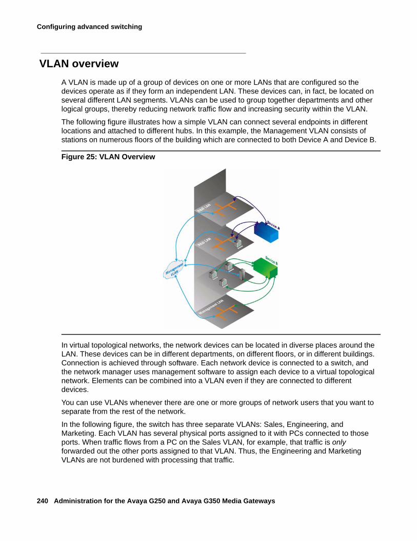
Configuring advanced switching
240 Administration for the Avaya G250 and Avaya G350 Media Gateways
VLAN overviewA VLAN is made up of a group of devices on one or more LANs that are configured so the devices operate as if they form an independent LAN. These devices can, in fact, be located on several different LAN segments. VLANs can be used to group together departments and other logical groups, thereby reducing network traffic flow and increasing security within the VLAN.
The following figure illustrates how a simple VLAN can connect several endpoints in different locations and attached to different hubs. In this example, the Management VLAN consists of stations on numerous floors of the building which are connected to both Device A and Device B.
Figure 25: VLAN Overview
In virtual topological networks, the network devices can be located in diverse places around the LAN. These devices can be in different departments, on different floors, or in different buildings. Connection is achieved through software. Each network device is connected to a switch, and the network manager uses management software to assign each device to a virtual topological network. Elements can be combined into a VLAN even if they are connected to different devices.
You can use VLANs whenever there are one or more groups of network users that you want to separate from the rest of the network.
In the following figure, the switch has three separate VLANs: Sales, Engineering, and Marketing. Each VLAN has several physical ports assigned to it with PCs connected to those ports. When traffic flows from a PC on the Sales VLAN, for example, that traffic is only forwarded out the other ports assigned to that VLAN. Thus, the Engineering and Marketing VLANs are not burdened with processing that traffic.
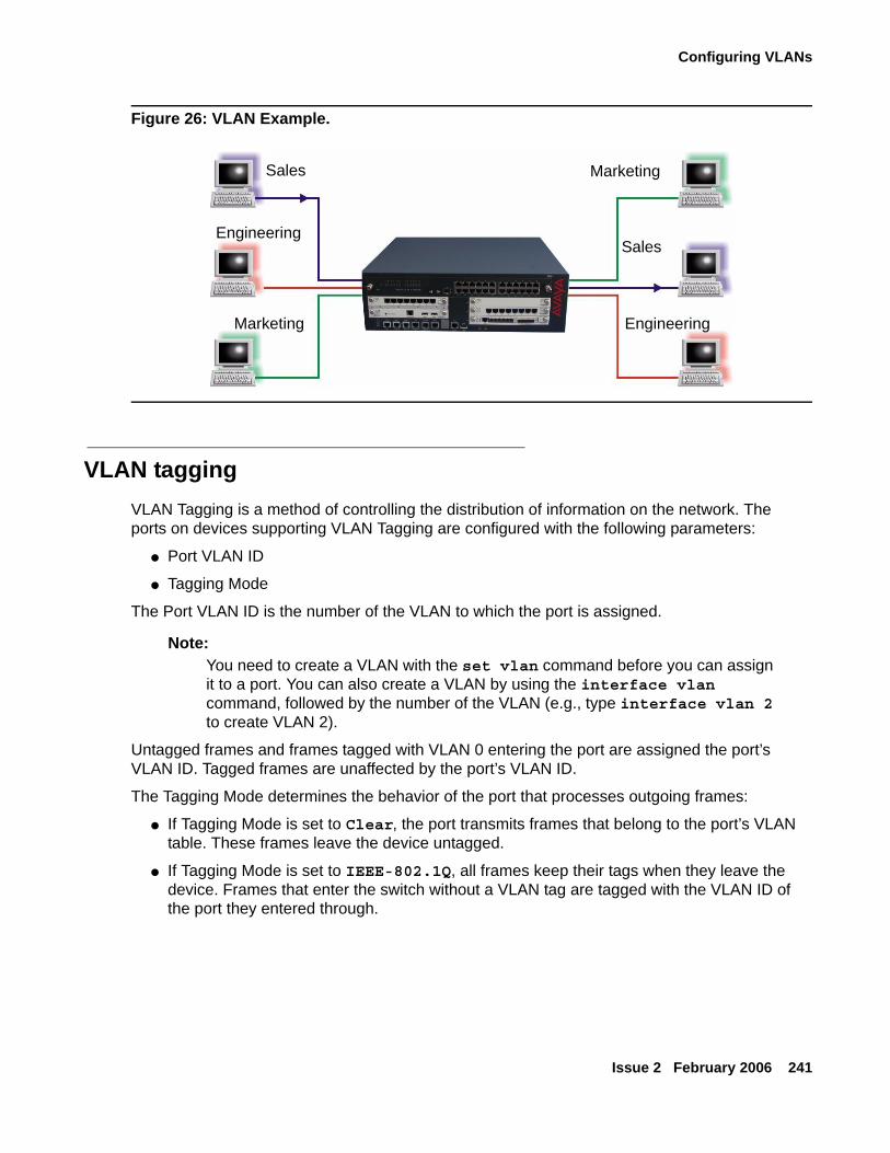
Configuring VLANs
Issue 2 February 2006 241
Figure 26: VLAN Example.
VLAN taggingVLAN Tagging is a method of controlling the distribution of information on the network. The ports on devices supporting VLAN Tagging are configured with the following parameters:
● Port VLAN ID
● Tagging Mode
The Port VLAN ID is the number of the VLAN to which the port is assigned.
Note:Note: You need to create a VLAN with the set vlan command before you can assign
it to a port. You can also create a VLAN by using the interface vlan command, followed by the number of the VLAN (e.g., type interface vlan 2 to create VLAN 2).
Untagged frames and frames tagged with VLAN 0 entering the port are assigned the port’s VLAN ID. Tagged frames are unaffected by the port’s VLAN ID.
The Tagging Mode determines the behavior of the port that processes outgoing frames:
● If Tagging Mode is set to Clear, the port transmits frames that belong to the port’s VLAN table. These frames leave the device untagged.
● If Tagging Mode is set to IEEE-802.1Q, all frames keep their tags when they leave the device. Frames that enter the switch without a VLAN tag are tagged with the VLAN ID of the port they entered through.
Sales
Sales
Marketing Engineering
Engineering
Marketing
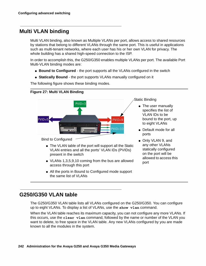
Configuring advanced switching
242 Administration for the Avaya G250 and Avaya G350 Media Gateways
Multi VLAN bindingMulti VLAN binding, also known as Multiple VLANs per port, allows access to shared resources by stations that belong to different VLANs through the same port. This is useful in applications such as multi-tenant networks, where each user has his or her own VLAN for privacy. The whole building has a shared high-speed connection to the ISP.
In order to accomplish this, the G250/G350 enables multiple VLANs per port. The available Port Multi-VLAN binding modes are:
● Bound to Configured - the port supports all the VLANs configured in the switch
● Statically Bound - the port supports VLANs manually configured on it
The following figure shows these binding modes.
Figure 27: Multi VLAN Binding
G250/G350 VLAN tableThe G250/G350 VLAN table lists all VLANs configured on the G250/G350. You can configure up to eight VLANs. To display a list of VLANs, use the show vlan command.When the VLAN table reaches its maximum capacity, you can not configure any more VLANs. If this occurs, use the clear vlan command, followed by the name or number of the VLAN you want to delete, to free space in the VLAN table. Any new VLANs configured by you are made known to all the modules in the system.
Static Binding
● The user manually specifies the list of VLAN IDs to be bound to the port, up to eight VLANs
● Default mode for all ports
● Only VLAN 9, and any other VLANs statically configured on the port will be allowed to access this port
Bind to Configured
● The VLAN table of the port will support all the Static VLAN entries and all the ports’ VLAN IDs (PVIDs) present in the switch
● VLANs 1,3,5,9,10 coming from the bus are allowed access through this port
● All the ports in Bound to Configured mode support the same list of VLANs
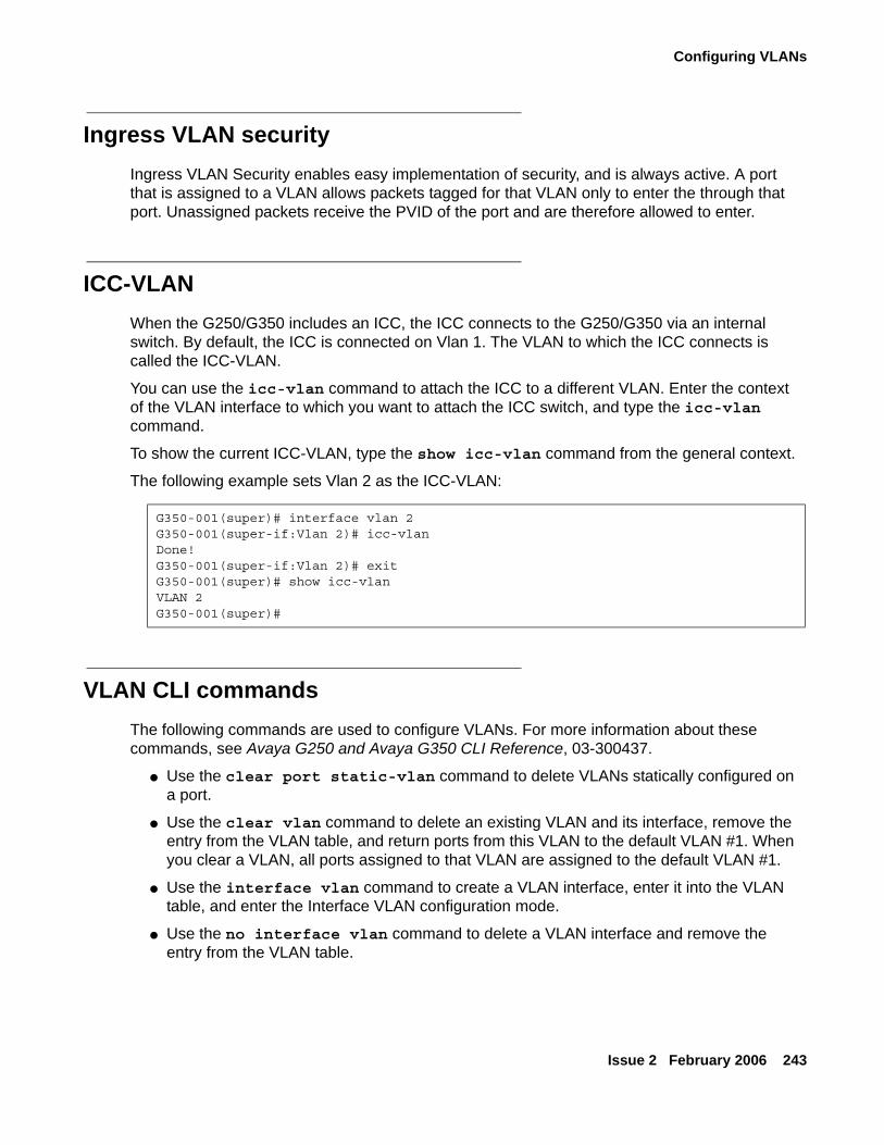
Configuring VLANs
Issue 2 February 2006 243
Ingress VLAN securityIngress VLAN Security enables easy implementation of security, and is always active. A port that is assigned to a VLAN allows packets tagged for that VLAN only to enter the through that port. Unassigned packets receive the PVID of the port and are therefore allowed to enter.
ICC-VLANWhen the G250/G350 includes an ICC, the ICC connects to the G250/G350 via an internal switch. By default, the ICC is connected on Vlan 1. The VLAN to which the ICC connects is called the ICC-VLAN.
You can use the icc-vlan command to attach the ICC to a different VLAN. Enter the context of the VLAN interface to which you want to attach the ICC switch, and type the icc-vlan command.
To show the current ICC-VLAN, type the show icc-vlan command from the general context.
The following example sets Vlan 2 as the ICC-VLAN:
VLAN CLI commandsThe following commands are used to configure VLANs. For more information about these commands, see Avaya G250 and Avaya G350 CLI Reference, 03-300437.
● Use the clear port static-vlan command to delete VLANs statically configured on a port.
● Use the clear vlan command to delete an existing VLAN and its interface, remove the entry from the VLAN table, and return ports from this VLAN to the default VLAN #1. When you clear a VLAN, all ports assigned to that VLAN are assigned to the default VLAN #1.
● Use the interface vlan command to create a VLAN interface, enter it into the VLAN table, and enter the Interface VLAN configuration mode.
● Use the no interface vlan command to delete a VLAN interface and remove the entry from the VLAN table.
G350-001(super)# interface vlan 2G350-001(super-if:Vlan 2)# icc-vlanDone!G350-001(super-if:Vlan 2)# exitG350-001(super)# show icc-vlanVLAN 2G350-001(super)#
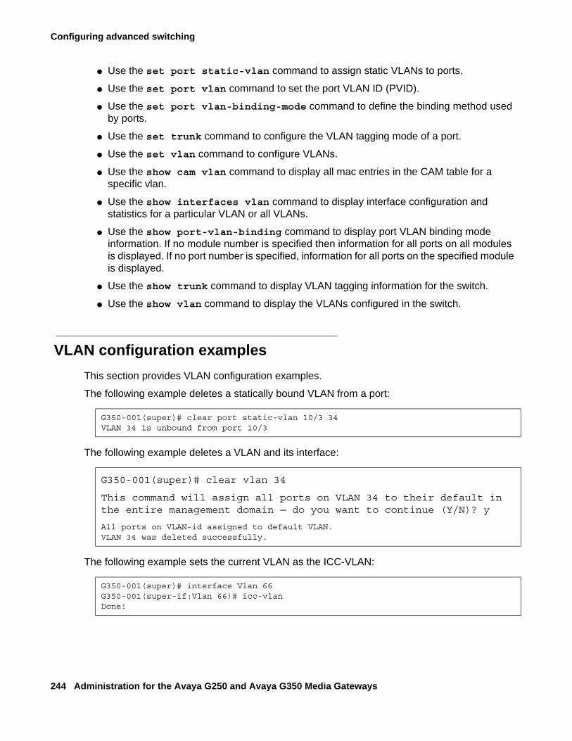
Configuring advanced switching
244 Administration for the Avaya G250 and Avaya G350 Media Gateways
● Use the set port static-vlan command to assign static VLANs to ports.
● Use the set port vlan command to set the port VLAN ID (PVID).
● Use the set port vlan-binding-mode command to define the binding method used by ports.
● Use the set trunk command to configure the VLAN tagging mode of a port.
● Use the set vlan command to configure VLANs.
● Use the show cam vlan command to display all mac entries in the CAM table for a specific vlan.
● Use the show interfaces vlan command to display interface configuration and statistics for a particular VLAN or all VLANs.
● Use the show port-vlan-binding command to display port VLAN binding mode information. If no module number is specified then information for all ports on all modules is displayed. If no port number is specified, information for all ports on the specified module is displayed.
● Use the show trunk command to display VLAN tagging information for the switch.
● Use the show vlan command to display the VLANs configured in the switch.
VLAN configuration examplesThis section provides VLAN configuration examples.
The following example deletes a statically bound VLAN from a port:
The following example deletes a VLAN and its interface:
The following example sets the current VLAN as the ICC-VLAN:
G350-001(super)# clear port static-vlan 10/3 34VLAN 34 is unbound from port 10/3
G350-001(super)# clear vlan 34
This command will assign all ports on VLAN 34 to their default in the entire management domain — do you want to continue (Y/N)? y
All ports on VLAN-id assigned to default VLAN.VLAN 34 was deleted successfully.
G350-001(super)# interface Vlan 66G350-001(super-if:Vlan 66)# icc-vlanDone!
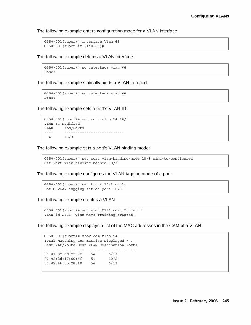
Configuring VLANs
Issue 2 February 2006 245
The following example enters configuration mode for a VLAN interface:
The following example deletes a VLAN interface:
The following example statically binds a VLAN to a port:
The following example sets a port’s VLAN ID:
The following example sets a port’s VLAN binding mode:
The following example configures the VLAN tagging mode of a port:
The following example creates a VLAN:
The following example displays a list of the MAC addresses in the CAM of a VLAN:
G350-001(super)# interface Vlan 66G350-001(super-if:Vlan 66)#
G350-001(super)# no interface vlan 66Done!
G350-001(super)# no interface vlan 66Done!
G350-001(super)# set port vlan 54 10/3VLAN 54 modifiedVLAN Mod/Ports---- ---------------------------54 10/3
G350-001(super)# set port vlan-binding-mode 10/3 bind-to-configuredSet Port vlan binding method:10/3
G350-001(super)# set trunk 10/3 dot1qDot1Q VLAN tagging set on port 10/3.
G350-001(super)# set vlan 2121 name TrainingVLAN id 2121, vlan-name Training created.
G350-001(super)# show cam vlan 54Total Matching CAM Entries Displayed = 3Dest MAC/Route Dest VLAN Destination Ports------------------- ---- -----------------00:01:02:dd:2f:9f 54 6/1300:02:2d:47:00:6f 54 10/200:02:4b:5b:28:40 54 6/13
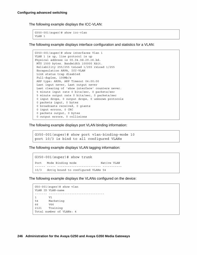
Configuring advanced switching
246 Administration for the Avaya G250 and Avaya G350 Media Gateways
The following example displays the ICC-VLAN:
The following example displays interface configuration and statistics for a VLAN:
The following example displays port VLAN binding information:
The following example displays VLAN tagging information:
The following example displays the VLANs configured on the device:
G350-001(super)# show icc-vlanVLAN 1
G350-001(super)# show interfaces Vlan 1VLAN 1 is up, line protocol is upPhysical address is 00.04.0d.29.c6.bd. MTU 1500 bytes. Bandwidth 100000 kbit. Reliability 255/255 txLoad 1/255 rxLoad 1/255 Encapsulation ARPA, ICC-VLAN Link status trap disabled Full-duplex, 100Mb/s ARP type: ARPA, ARP Timeout 04:00:00 Last input never, Last output never Last clearing of 'show interface' counters never. 5 minute input rate 0 bits/sec, 0 packets/sec 5 minute output rate 0 bits/sec, 0 packets/sec 0 input drops, 0 output drops, 0 unknown protocols 0 packets input, 0 bytes 0 broadcasts received, 0 giants 0 input errors, 0 CRC 0 packets output, 0 bytes 0 output errors, 0 collisions
G350-001(super)# show port vlan-binding-mode 10port 10/3 is bind to all configured VLANs
G350-001(super)# show trunk
Port Mode Binding mode Native VLAN------ ----- ------------------------- -----------10/3 dot1q bound to configured VLANs 54
G50-001(super)# show vlanVLAN ID VLAN-name------- --------------------------------1 V154 Marketing66 V662121 TrainingTotal number of VLANs: 4
Configuring port redundancy (G350 only)
Issue 2 February 2006 247
Configuring port redundancy (G350 only)This section contains information about port redundancy configuration on G350 switch ports and includes the following topics:
● Port redundancy overview — an overview of port redundancy on the G350
● Secondary port activation — a description of how the secondary port is activated
● Switchback — a description of how switchback occurs
● Port redundancy CLI commands — a list and description of the CLI commands used to configure port redundancy
● Port redundancy configuration examples — examples of port redundancy configurations
Note:Note: Port redundancy is not supported on the G250.
Port redundancy overviewRedundancy involves the duplication of devices, services, or connections, so, in the event of a failure, the redundant duplicate can take over for the one that failed.
Since computer networks are critical for business operations, it is vital to ensure that the network continues to function even if a piece of equipment fails. Even the most reliable equipment might fail on occasion, but a redundant component can ensure that the network continues to operate despite such failure.
To achieve port redundancy, you can define a redundancy relationship between any two ports in a switch. One port is defined as the primary port and the other as the secondary port. If the primary port fails, the secondary port takes over.
You can configure up to 25 pairs of ports per chassis. Each pair contains a primary and secondary port. You can configure any type of Ethernet port to be redundant to any other. You can configure redundant ports from among the Ethernet LAN port on the G350 front panel and the Ethernet ports (1-24) and the Gigabit Ethernet port (51) on the MM314 Media Module or the Ethernet ports (1-40) and the Gigabit Ethernet port (51) on the MM316 Media Module.
Secondary port activationThe secondary port takes over within one second and is activated when the primary port link stops functioning. Subsequent switchovers take place after the minimum time between switchovers has elapsed. To set the minimum time between switchovers, use the set port redundancy-intervals command.
Configuring advanced switching
248 Administration for the Avaya G250 and Avaya G350 Media Gateways
SwitchbackIf switchback is enabled and the primary port recovers, a switchback takes place. Use the set port redundancy-intervals command to set the following switchback parameters:
● min-time-between-switchovers — the minimum time that is allowed to elapse before a primary-backup switchover
● switchback-interval — the minimum time the primary port link has to be up before a switchback to the primary port takes place. If you set this to none, there is no switchback to the primary port when it recovers. In this case, switchback to the primary port only takes place if the secondary port fails.
Port redundancy CLI commandsThe following commands are used to configure port redundancy. For more information about these commands, see Avaya G250 and Avaya G350 CLI Reference, 03-300437.
● Use the set port redundancy enable/disable command to globally enable or disable the redundancy pairs you have defined. Using this command will not delete existing redundancy entries.
● Use the set port redundancy on/off command to define or remove redundancy pairs. Use the show port redundancy command to ensure that there is no redundancy scheme already defined on any of the links.
● Use the set port redundancy-intervals command to configure the two time constants that determine redundancy switchover parameters.
● Use the show port redundancy command to display information about software port redundancy schemes defined for the switch.
Note:Note: If you configure the Ethernet LAN port on the G350 front panel to be redundant
with the Gigabit Ethernet port on the MM314 or MM316 Media Module, the Ethernet LAN port becomes the primary port after resetting the G350 even if you configured the Gigabit Ethernet port to be primary. To prevent this, use the set port redundancy-intervals command with the switchback interval parameter set to 0.
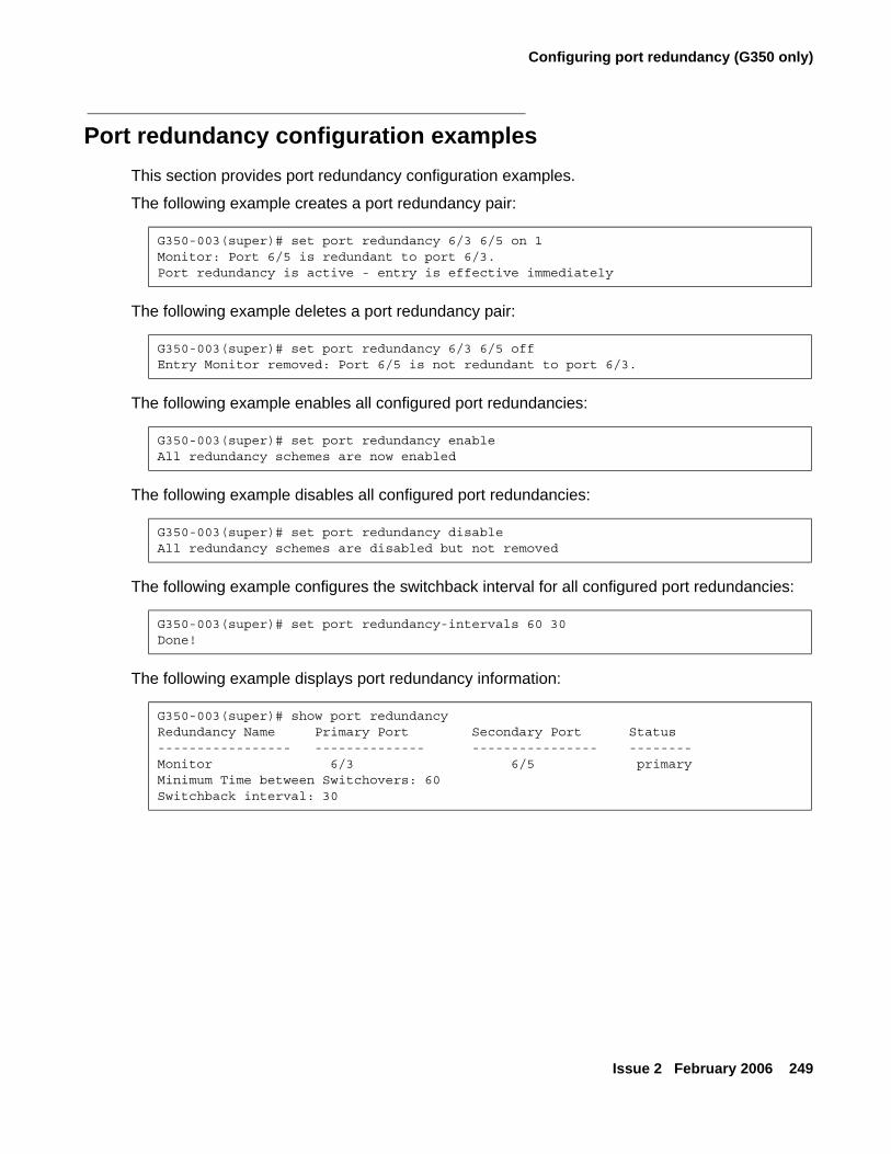
Configuring port redundancy (G350 only)
Issue 2 February 2006 249
Port redundancy configuration examplesThis section provides port redundancy configuration examples.
The following example creates a port redundancy pair:
The following example deletes a port redundancy pair:
The following example enables all configured port redundancies:
The following example disables all configured port redundancies:
The following example configures the switchback interval for all configured port redundancies:
The following example displays port redundancy information:
G350-003(super)# set port redundancy 6/3 6/5 on 1Monitor: Port 6/5 is redundant to port 6/3.Port redundancy is active - entry is effective immediately
G350-003(super)# set port redundancy 6/3 6/5 offEntry Monitor removed: Port 6/5 is not redundant to port 6/3.
G350-003(super)# set port redundancy enableAll redundancy schemes are now enabled
G350-003(super)# set port redundancy disableAll redundancy schemes are disabled but not removed
G350-003(super)# set port redundancy-intervals 60 30Done!
G350-003(super)# show port redundancyRedundancy Name Primary Port Secondary Port Status----------------- -------------- ---------------- --------Monitor 6/3 6/5 primaryMinimum Time between Switchovers: 60Switchback interval: 30
Configuring advanced switching
250 Administration for the Avaya G250 and Avaya G350 Media Gateways
Configuring port mirroringThis section provides information about configuring port mirroring on G250/G350 devices and includes the following topics:
● Port mirroring overview — an overview of port mirroring on the G250/G350
● Port mirroring CLI commands — a list and description of the CLI commands used to configure port mirroring on the G250/G350
● Port mirroring configuration examples — examples of port mirroring configurations
Port mirroring overviewPort Mirroring copies all received and transmitted packets (including local traffic) from a source port to a predefined destination port, in addition to the normal destination port of the packets. Port Mirroring, also known as “sniffing,” is useful in debugging network problems.
Port mirroring allows you to define a source port and a destination port, regardless of port type. For example, a 10 Mbps and a 100 Mbps port can form a valid source/destination pair. You cannot, however define the port mirroring source and destination ports as the same source and destination port.
You can define one source port and one destination port on each G250/G350 for received (Rx), transmitted (Tx), or transmitted and received (both) traffic.
Port mirroring constraintsYou cannot use the LAN port on the G350 front panel or the WAN Fast Ethernet port on the G250 and G350 front panels in port mirroring.
Port mirroring CLI commandsThe following commands are used to configure port mirroring on the G250/G350. For more information about these commands, see Avaya G250 and Avaya G350 CLI Reference, 03-300437.
● Use the set port mirror command to define a port mirroring pair in the switch.
● Use the show port mirror command to display mirroring information for the switch.
● Use the clear port mirror command to cancel port mirroring.
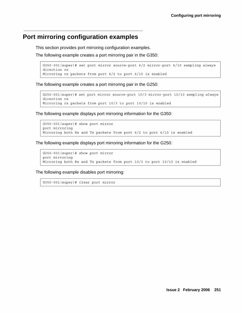
Configuring port mirroring
Issue 2 February 2006 251
Port mirroring configuration examplesThis section provides port mirroring configuration examples.
The following example creates a port mirroring pair in the G350:
The following example creates a port mirroring pair in the G250:
The following example displays port mirroring information for the G350:
The following example displays port mirroring information for the G250:
The following example disables port mirroring:
G350-001(super)# set port mirror source-port 6/2 mirror-port 6/10 sampling always direction rxMirroring rx packets from port 6/2 to port 6/10 is enabled
G250-001(super)# set port mirror source-port 10/3 mirror-port 10/10 sampling always direction rxMirroring rx packets from port 10/3 to port 10/10 is enabled
G350-001(super)# show port mirrorport mirroringMirroring both Rx and Tx packets from port 6/2 to port 6/10 is enabled
G250-001(super)# show port mirrorport mirroringMirroring both Rx and Tx packets from port 10/3 to port 10/10 is enabled
G350-001(super)# clear port mirror
Configuring advanced switching
252 Administration for the Avaya G250 and Avaya G350 Media Gateways
Configuring spanning tree (G350 only)This section provides information about configuring spanning tree on the G350 and contains the following topics:
● Spanning tree overview — an overview of spanning tree protocol
● Spanning tree CLI commands — a list and description of CLI commands used to configure spanning tree protocol on the G350
● Spanning tree configuration examples — examples of spanning tree protocol configurations
Note:Note: Spanning tree is not supported on the G250.
Spanning tree overviewG350 devices support the enhanced Rapid Spanning Tree protocol (802.1w). The 802.1w standard is a faster and more sophisticated version of the 802.1d (STP) standard, and includes backward compatibility with 802.1d. Spanning Tree makes it possible to recover connectivity after an outage within a minute or so. RSTP, with its “rapid” algorithm, can usually restore connectivity to a network where a backbone link has failed in much less time.
Spanning tree protocol
The Spanning Tree Algorithm ensures the existence of a loop-free topology in networks that contain parallel bridges. A loop occurs when there are alternate routes between hosts. If there is a loop in an extended network, bridges may forward traffic indefinitely, which can result in increased traffic and degradation in network performance.
The Spanning Tree Algorithm:
● Produces a logical tree topology out of any arrangement of bridges. The result is a single path between any two end stations on an extended network.
● Provides a high degree of fault tolerance. It allows the network to automatically reconfigure the spanning tree topology if there is a bridge or data-path failure.
The Spanning Tree Algorithm requires five values to derive the spanning tree topology. These are:
● A multicast address specifying all bridges on the extended network. This address is media-dependent and is automatically determined by the software.
● A network-unique identifier for each bridge on the extended network.
● A unique identifier for each bridge/LAN interface (a port).
Configuring spanning tree (G350 only)
Issue 2 February 2006 253
● The relative priority of each port.
● The cost of each port.
After these values are assigned, bridges multicast and process the formatted frames (called Bridge Protocol Data Units, or BPDUs) to derive a single, loop-free topology throughout the extended network. The bridges exchange BPDU frames quickly, minimizing the time that service is unavailable between hosts.
Spanning tree per port
Spanning tree can take up to 30 seconds to open traffic on a port. This delay can cause problems on ports carrying time-sensitive traffic. You can therefore enable or disable spanning tree in the G350 on a per-port basis to minimize this effect.
Rapid Spanning Tree Protocol (RSTP)
About the 802.1w (RSTP) standardThe enhanced feature set of the 802.1w standard includes:
● Bridge Protocol Data Unit (BPDU) type 2
● New port roles: Alternate port, Backup port
● Direct handshaking between adjacent bridges regarding a desired topology change (TC). This eliminates the need to wait for the timer to expire.
● Improvement in the time it takes to propagate TC information. Specifically, TC information does not have to be propagated all the way back to the Root Bridge (and back) to be changed.
● Origination of BPDUs on a port-by-port basis
Port rolesAt the center of RSTP — specifically as an improvement over STP (802.1d) — are the roles that are assigned to the ports. There are four port roles:
● Root port — port closest to the root bridge
● Designated port — corresponding port on the remote bridge of the local root port
● Alternate port — an alternate route to the root
● Backup port — an alternate route to the network segment
The RSTP algorithm usually makes it possible to change port roles rapidly through its fast topology change propagation mechanism. For example, a port in the blocking state can be assigned the role of alternate port. When the backbone of the network fails the port can rapidly be changed to forwarding.
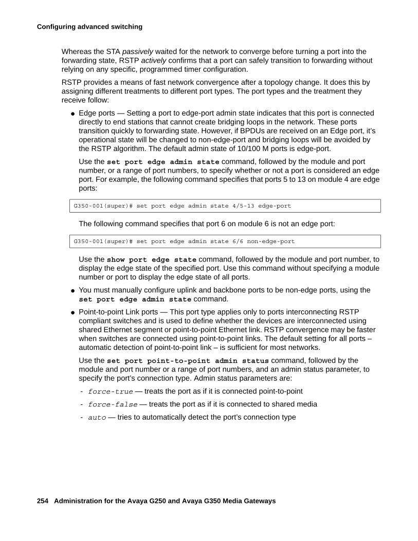
Configuring advanced switching
254 Administration for the Avaya G250 and Avaya G350 Media Gateways
Whereas the STA passively waited for the network to converge before turning a port into the forwarding state, RSTP actively confirms that a port can safely transition to forwarding without relying on any specific, programmed timer configuration.
RSTP provides a means of fast network convergence after a topology change. It does this by assigning different treatments to different port types. The port types and the treatment they receive follow:
● Edge ports — Setting a port to edge-port admin state indicates that this port is connected directly to end stations that cannot create bridging loops in the network. These ports transition quickly to forwarding state. However, if BPDUs are received on an Edge port, it’s operational state will be changed to non-edge-port and bridging loops will be avoided by the RSTP algorithm. The default admin state of 10/100 M ports is edge-port.
Use the set port edge admin state command, followed by the module and port number, or a range of port numbers, to specify whether or not a port is considered an edge port. For example, the following command specifies that ports 5 to 13 on module 4 are edge ports:
The following command specifies that port 6 on module 6 is not an edge port:
Use the show port edge state command, followed by the module and port number, to display the edge state of the specified port. Use this command without specifying a module number or port to display the edge state of all ports.
● You must manually configure uplink and backbone ports to be non-edge ports, using the set port edge admin state command.
● Point-to-point Link ports — This port type applies only to ports interconnecting RSTP compliant switches and is used to define whether the devices are interconnected using shared Ethernet segment or point-to-point Ethernet link. RSTP convergence may be faster when switches are connected using point-to-point links. The default setting for all ports – automatic detection of point-to-point link – is sufficient for most networks.
Use the set port point-to-point admin status command, followed by the module and port number or a range of port numbers, and an admin status parameter, to specify the port’s connection type. Admin status parameters are:
- force-true — treats the port as if it is connected point-to-point
- force-false — treats the port as if it is connected to shared media
- auto — tries to automatically detect the port’s connection type
G350-001(super)# set port edge admin state 4/5-13 edge-port
G350-001(super)# set port edge admin state 6/6 non-edge-port
Configuring spanning tree (G350 only)
Issue 2 February 2006 255
For example, the following command specifies that ports 3 to 5 on module 5 are treated is if they were connected point-to-point:
Use the show port point-to-point status command, followed by the module and port number, to display the point-to-point status of the specified point-to-point status of all ports.
Spanning tree CLI commandsUse the following commands to configure spanning tree. For more information about these commands, see Avaya G250 and Avaya G350 CLI Reference, 03-300437.
● Use the set port spantree command to enable or disable the spanning tree mode for specific switch ports.
● Use the set spantree default-path-cost command to set the version of the spanning tree default path cost used by this bridge.
● Use the set spantree enable/disable command to enable or disable the spanning tree algorithm.
● Use the set spantree forward-delay command to specify the time used when transferring the state of a port to the forwarding state.
● Use the set spantree hello-time command to specify the time interval between the generation of configuration BPDUs by the root.
● Use the set spantree max-age command to specify the time to keep an information message before it is discarded.
● Use the set spantree priority command to set the bridge priority for STP.
● Use the set spantree tx-hold-count command to set the value in packets used by the spanning tree in order to limit the maximum number of BPDUs transmitted during a hello-time period.
● Use the set spantree version command to set the version of the spanning tree protocol.
● Use the show spantree command to display spanning-tree information.
G350-001(super)# set port point-to-point admin status 5/3-5 force-true

Configuring advanced switching
256 Administration for the Avaya G250 and Avaya G350 Media Gateways
Spanning tree configuration examplesThis section provides spanning tree configuration examples.
The following example enables spanning tree on a port:
The following example disables spanning tree on a port:
The following example configures the version of the spanning tree default path cost used by this bridge:
GThe following example configures the time used when transferring the port to the forwarding state:
The following example configures the time interval between the generation of configuration BPDUs by the root:
The following example configures the amount of time an information message is kept before being discarded:
The following example configures the bridge priority for spanning tree:
The following example sets the value in packets used by spanning tree in order to limit the maximum number of BPDUs transmitted during a hello-time period:
G350-003(super)# set port spantree enable 6/8port 6/8 was enabled on spantree
G350-003(super)# set port spantree disable 6/8port 6/8 was disabled on spantree
350-003(super)# set spantree default-path-cost common-spanning-treeSpanning tree default path costs is set to common spanning tree.
G350-003(super)# set spantree forward-delay 16bridge forward delay is set to 16.
G350-003(super)# set spantree hello-time 2bridge hello time is set to 2.
G350-003(super)# set spantree max-age 21bridge max age is set to 21.
G350-003(super)# set spantree priority 36864Bridge priority set to 36864.
G350-003(super)# set spantree tx-hold-count 4tx hold count is set to 4.
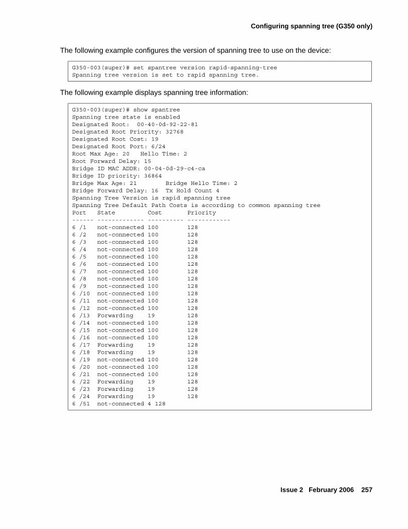
Configuring spanning tree (G350 only)
Issue 2 February 2006 257
The following example configures the version of spanning tree to use on the device:
The following example displays spanning tree information:
G350-003(super)# set spantree version rapid-spanning-treeSpanning tree version is set to rapid spanning tree.
G350-003(super)# show spantreeSpanning tree state is enabledDesignated Root: 00-40-0d-92-22-81Designated Root Priority: 32768Designated Root Cost: 19Designated Root Port: 6/24Root Max Age: 20 Hello Time: 2Root Forward Delay: 15Bridge ID MAC ADDR: 00-04-0d-29-c4-caBridge ID priority: 36864Bridge Max Age: 21 Bridge Hello Time: 2Bridge Forward Delay: 16 Tx Hold Count 4Spanning Tree Version is rapid spanning treeSpanning Tree Default Path Costs is according to common spanning treePort State Cost Priority------ ------------- ---------- ------------6 /1 not-connected 100 1286 /2 not-connected 100 1286 /3 not-connected 100 1286 /4 not-connected 100 1286 /5 not-connected 100 1286 /6 not-connected 100 1286 /7 not-connected 100 1286 /8 not-connected 100 1286 /9 not-connected 100 1286 /10 not-connected 100 1286 /11 not-connected 100 1286 /12 not-connected 100 1286 /13 Forwarding 19 1286 /14 not-connected 100 1286 /15 not-connected 100 1286 /16 not-connected 100 1286 /17 Forwarding 19 1286 /18 Forwarding 19 1286 /19 not-connected 100 1286 /20 not-connected 100 1286 /21 not-connected 100 1286 /22 Forwarding 19 1286 /23 Forwarding 19 1286 /24 Forwarding 19 1286 /51 not-connected 4 128
Configuring advanced switching
258 Administration for the Avaya G250 and Avaya G350 Media Gateways
Port classificationThis section provides information on configuring port classification on the G250/G350 and includes the following topics:
● Port classification overview — an overview of port classification on the G250/G350
● Port classification CLI commands — a list and description of the CLI commands used to configure port classification on the G250/G350
● Port classification configuration examples — examples of port classification configurations
Port classification overviewWith the G250/G350, you can classify any port as either regular or valuable. Classifying a port as valuable means that a link fault trap is sent in the event of a link failure. The trap is sent even when the port is disabled. This feature is particularly useful for the port redundancy application, where you need to be informed about a link failure on the dormant port.
Note:Note: The 1GB port is classified as valuable by default.
Port classification CLI commandsUse the following commands to configure port classification. For more information about these commands, see Avaya G250 and Avaya G350 CLI Reference, 03-300437.
● Use the set port classification command to set the port classification to either regular or valuable. Any change in the Spanning Tree state from Forwarding for a valuable port will erase all learned MAC addresses in the switch.
● Use the show port classification command to display a port’s classification.
Port classification configuration examplesThis section provides port classification configuration examples.
The following example classifies a port as a valuable port:
G350-003(super)# set port classification 6/4 valuablePort 6/4 classification has been changed.
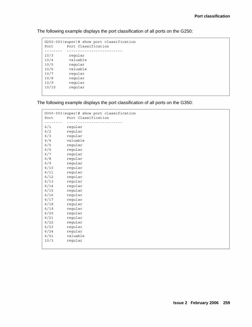
Port classification
Issue 2 February 2006 259
The following example displays the port classification of all ports on the G250:
The following example displays the port classification of all ports on the G350:
G250-003(super)# show port classificationPort Port Classification-------- -------------------------10/3 regular10/4 valuable10/5 regular10/6 valuable10/7 regular10/8 regular10/9 regular10/10 regular
G350-003(super)# show port classificationPort Port Classification-------- -------------------------6/1 regular6/2 regular6/3 regular6/4 valuable6/5 regular6/6 regular6/7 regular6/8 regular6/9 regular6/10 regular6/11 regular6/12 regular6/13 regular6/14 regular6/15 regular6/16 regular6/17 regular6/18 regular6/19 regular6/20 regular6/21 regular6/22 regular6/23 regular6/24 regular6/51 valuable10/3 regular

Configuring advanced switching
260 Administration for the Avaya G250 and Avaya G350 Media Gateways
Issue 2 February 2006 261
Chapter 17: Configuring monitoring applications
The Avaya G250 and G350 Media Gateways provide several software tools for monitoring and diagnosing your network. Use these tools to monitor the status of your network operations, and to analyze the flow of information.
This chapter provides information on configuring monitoring tools on the G250/G350 and includes the following sections:
● Configuring RMON — instructions for configuring RMON monitoring on the G250/G350
● Configuring and analyzing RTP statistics — instructions for configuring and analyzing the results of RTP statistics monitoring, a QoS monitoring tool, on the G250/G350
● Configuring and analyzing packet sniffing — instructions for configuring and analyzing the results of the packet sniffing application
● Configuring and monitoring CNA test plugs — instructions for configuring CNA test plugs to register with the Converged Network Analyzer (CNA) system and monitoring test plug activity
Configuring RMONThis section provides information on monitoring the G250 and G350 using RMON and includes the following topics:
● RMON overview — an overview of the RMON network monitoring standard
● RMON CLI commands — a list and description of the CLI commands used to configure RMON monitoring on the G250/G350
● RMON configuration examples — examples of RMON configurations
RMON overviewRemote Monitoring (RMON), the internationally recognized network monitoring standard, is a network management protocol that allows network information to be gathered at a single workstation. You can use RMON probes to monitor and analyze a single segment only. When you deploy a switch on the network, there are additional components in the network that cannot be monitored using RMON. These components include the switch fabric, VLAN, and statistics for all ports.
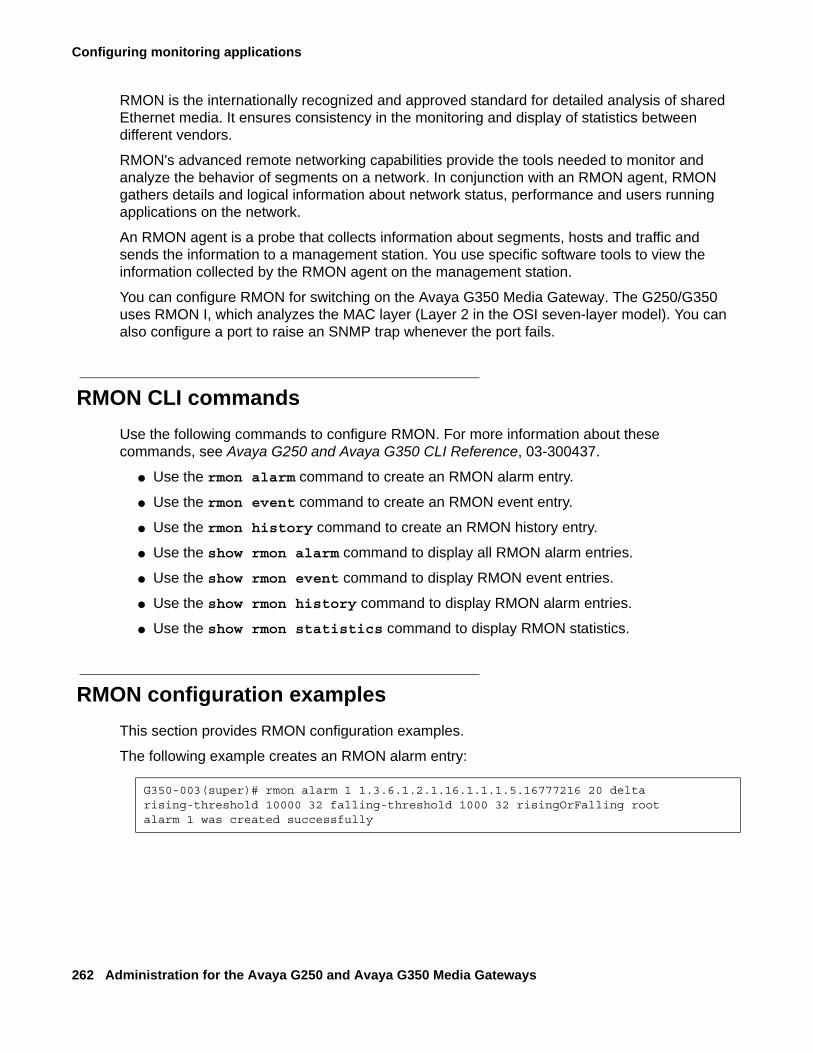
Configuring monitoring applications
262 Administration for the Avaya G250 and Avaya G350 Media Gateways
RMON is the internationally recognized and approved standard for detailed analysis of shared Ethernet media. It ensures consistency in the monitoring and display of statistics between different vendors.
RMON's advanced remote networking capabilities provide the tools needed to monitor and analyze the behavior of segments on a network. In conjunction with an RMON agent, RMON gathers details and logical information about network status, performance and users running applications on the network.
An RMON agent is a probe that collects information about segments, hosts and traffic and sends the information to a management station. You use specific software tools to view the information collected by the RMON agent on the management station.
You can configure RMON for switching on the Avaya G350 Media Gateway. The G250/G350 uses RMON I, which analyzes the MAC layer (Layer 2 in the OSI seven-layer model). You can also configure a port to raise an SNMP trap whenever the port fails.
RMON CLI commandsUse the following commands to configure RMON. For more information about these commands, see Avaya G250 and Avaya G350 CLI Reference, 03-300437.
● Use the rmon alarm command to create an RMON alarm entry.
● Use the rmon event command to create an RMON event entry.
● Use the rmon history command to create an RMON history entry.
● Use the show rmon alarm command to display all RMON alarm entries.
● Use the show rmon event command to display RMON event entries.
● Use the show rmon history command to display RMON alarm entries.
● Use the show rmon statistics command to display RMON statistics.
RMON configuration examplesThis section provides RMON configuration examples.
The following example creates an RMON alarm entry:
G350-003(super)# rmon alarm 1 1.3.6.1.2.1.16.1.1.1.5.16777216 20 delta rising-threshold 10000 32 falling-threshold 1000 32 risingOrFalling rootalarm 1 was created successfully
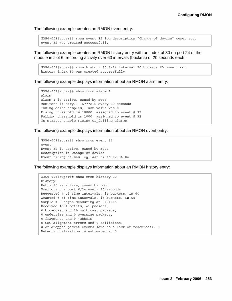
Configuring RMON
Issue 2 February 2006 263
The following example creates an RMON event entry:
The following example creates an RMON history entry with an index of 80 on port 24 of the module in slot 6, recording activity over 60 intervals (buckets) of 20 seconds each.
The following example displays information about an RMON alarm entry:
The following example displays information about an RMON event entry:
The following example displays information about an RMON history entry:
G350-003(super)# rmon event 32 log description “Change of device” owner rootevent 32 was created successfully
G350-003(super)# rmon history 80 6/24 interval 20 buckets 60 owner roothistory index 80 was created successfully
G350-003(super)# show rmon alarm 1alarmalarm 1 is active, owned by rootMonitors ifEntry.1.16777216 every 20 secondsTaking delta samples, last value was 0Rising threshold is 10000, assigned to event # 32Falling threshold is 1000, assigned to event # 32On startup enable rising or_falling alarms
G350-003(super)# show rmon event 32eventEvent 32 is active, owned by rootDescription is Change of deviceEvent firing causes log,last fired 12:36:04
G350-003(super)# show rmon history 80historyEntry 80 is active, owned by rootMonitors the port 6/24 every 20 secondsRequested # of time intervals, ie buckets, is 60Granted # of time intervals, ie buckets, is 60Sample # 2 began measuring at 0:21:16Received 4081 octets, 41 packets,0 broadcast and 10 multicast packets,0 undersize and 0 oversize packets,0 fragments and 0 jabbers,0 CRC alignment errors and 0 collisions,# of dropped packet events (due to a lack of resources): 0Network utilization is estimated at 0
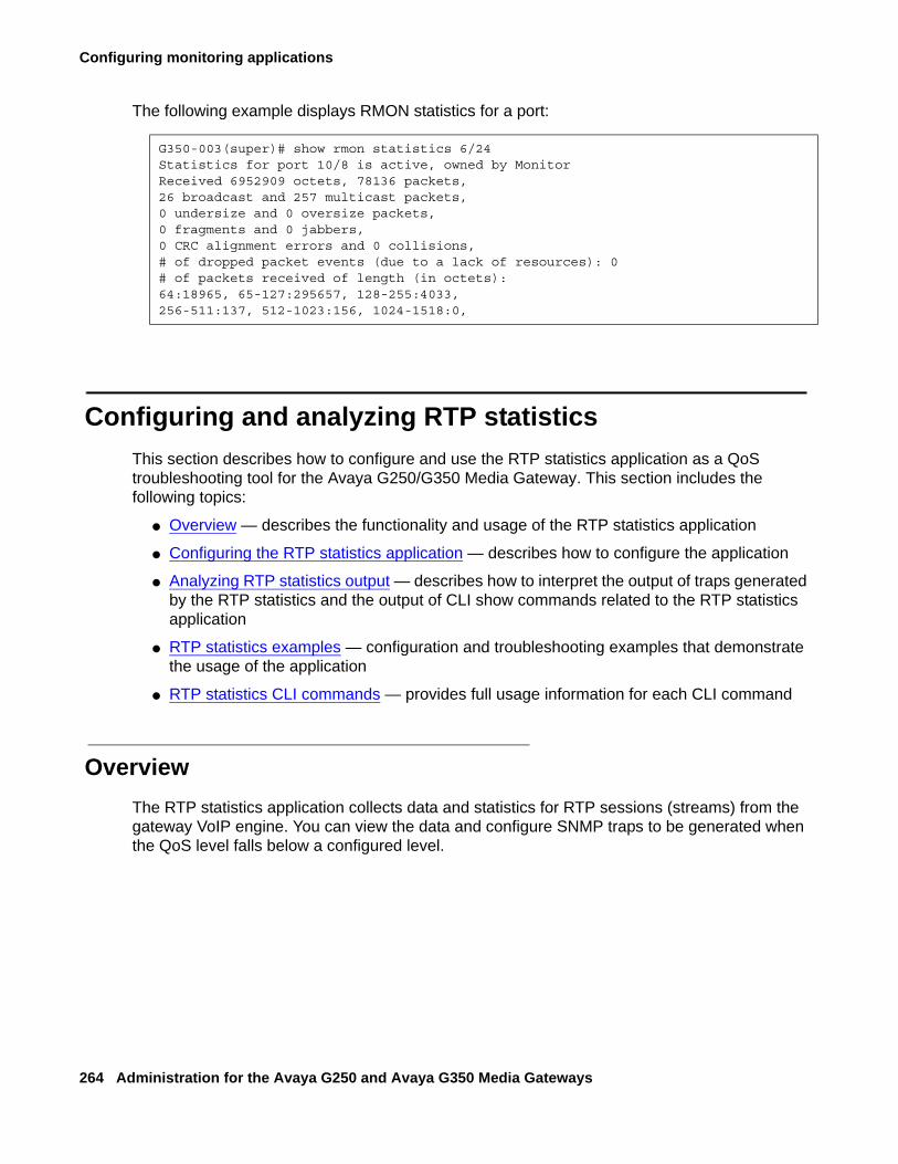
Configuring monitoring applications
264 Administration for the Avaya G250 and Avaya G350 Media Gateways
The following example displays RMON statistics for a port:
Configuring and analyzing RTP statisticsThis section describes how to configure and use the RTP statistics application as a QoS troubleshooting tool for the Avaya G250/G350 Media Gateway. This section includes the following topics:
● Overview — describes the functionality and usage of the RTP statistics application
● Configuring the RTP statistics application — describes how to configure the application
● Analyzing RTP statistics output — describes how to interpret the output of traps generated by the RTP statistics and the output of CLI show commands related to the RTP statistics application
● RTP statistics examples — configuration and troubleshooting examples that demonstrate the usage of the application
● RTP statistics CLI commands — provides full usage information for each CLI command
OverviewThe RTP statistics application collects data and statistics for RTP sessions (streams) from the gateway VoIP engine. You can view the data and configure SNMP traps to be generated when the QoS level falls below a configured level.
G350-003(super)# show rmon statistics 6/24Statistics for port 10/8 is active, owned by MonitorReceived 6952909 octets, 78136 packets,26 broadcast and 257 multicast packets,0 undersize and 0 oversize packets,0 fragments and 0 jabbers,0 CRC alignment errors and 0 collisions,# of dropped packet events (due to a lack of resources): 0# of packets received of length (in octets):64:18965, 65-127:295657, 128-255:4033,256-511:137, 512-1023:156, 1024-1518:0,
Configuring and analyzing RTP statistics
Issue 2 February 2006 265
Note:Note: An alternative tool available from Avaya for debugging QoS problems is VMON.
VMON is an RTCP QoS reports collector. VMON support, available in all Avaya devices, is the capability of a VoIP device to send a copy of an RTCP message to the IP address of a VMON server. VMON can collect RTCP reports, store them to its host hard disk, and analyze and generate graphic reports. However, VMON requires a dedicated Windows server. The RTP statistics application runs on the G250/G350’s firmware, and does not require any dedicated hardware. For information about configuring VMON in Avaya Communication Manager, see Administrator Guide for Avaya Communication Manager, 03-300509.
Note:Note: The gateway performs traceroutes whenever RTP statistics is enabled.
The RTP statistics application provides the following functionality:
● Collects QoS data from the gateway VoIP engine(s), including Real-Time Control Protocol (RTCP) data, traceroute reports, and information from the DSP regarding jitter buffer, internal delays, and so on.
Note:Note: RTCP is a standard QoS report companion protocol to RTP. RTP endpoints
periodically send RTCP report packets to their remote peer (or peers in multicast). RTCP reports include QoS data such as delay, jitter, and loss.
● Collects call data from the gateway, such as duration, start-time, and end-time.
● Displays the RTP statistics in CLI and MIB formats.
● Displays summary reports for the VoIP engine(s).
● Assesses QoS status based on configurable thresholds on an extensive set of QoS metrics.
● Generates QoS traps. QoS traps are notifications sent via SNMP upon termination of an RTP stream that suffers from bad QoS. These notifications include extensive data about the session that enables offline troubleshooting of QoS problems.The trap rate is controlled by a configurable trap rate limiter.
Note:Note: QoS trap generation is an especially convenient troubleshooting tool for large
installations, since all devices that support the RTP statistics application can be configured to send traps to a single SNMP trap manager.
● Generates QoS fault and clear traps. QoS fault traps are notifications that are sent when more than a configurable number of active sessions have QoS indicators over the configured thresholds. A QoS clear trap is a notification that is sent after a QoS fault trap when the number of active RTP sessions with QoS indicators over the configured thresholds reduces to a specified number.
Configuring monitoring applications
266 Administration for the Avaya G250 and Avaya G350 Media Gateways
Configuring the RTP statistics applicationTo configure the RTP statistics application, work through the following sections, in order:
● Viewing RTP statistics thresholds
● Configuring RTP statistics thresholds
● Enabling and resetting the RTP statistics application
● Viewing application configuration
● Configuring QoS traps
● Configuring QoS fault and clear traps
● Configuring the trap rate limiter
Viewing RTP statistics thresholds
The RTP statistics application uses a system of thresholds to evaluate levels of QoS during RTP sessions. The thresholds are configured on several QoS metrics. Your configuration of the thresholds determines when the application evaluates a session as having bad QoS conditions. This section describes the thresholds that you can configure, how you can view the thresholds that are currently configured, and the metrics on which you can configure them.The RTP statistics application samples the VoIP engine every RTCP interval, which is configured in Avaya Communication Manager, where it is called “RTCP Report Period”. For information about configuring the RTCP interval (RTCP report period), see Administrator Guide for Avaya Communication Manager, 03-300509. The RTCP interval is typically 5 to 8 seconds.There are three types of thresholds:
● A threshold on a metric. For example, you can configure a threshold on the metric ‘packet loss’. The application samples the metric every RTP interval and increments a counter (event counter) if the sampled value is over the threshold. Hence, the 'event-counter' represents the number of times the metric was sampled over its threshold.
● An event threshold. An event threshold is a threshold on an event counter. If QoS traps are configured, the application generates a QoS trap when, at the end of a session, one or more event counters are over their event thresholds. For example, if the event threshold for packet loss is 2, the application generates a QoS trap if packet loss is sampled over its threshold two or more times.
● Thresholds on metric averages. The application calculates averages of some of the metrics. When an RTP session terminates, the application evaluates the average metrics and generates a QoS trap (if QoS traps are configured) if one of them is over its corresponding threshold.
Note:Note: All CLI commands described in this section are available in the general context of
the CLI.
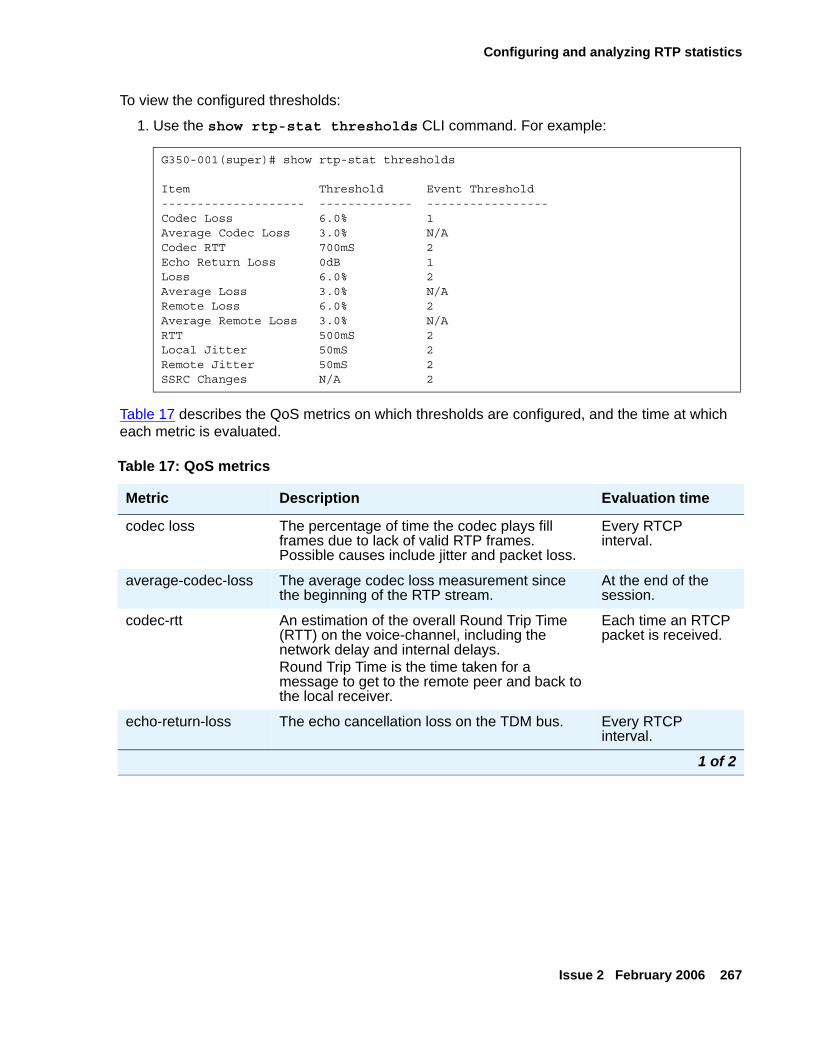
Configuring and analyzing RTP statistics
Issue 2 February 2006 267
To view the configured thresholds:
1. Use the show rtp-stat thresholds CLI command. For example:
Table 17 describes the QoS metrics on which thresholds are configured, and the time at which each metric is evaluated.
G350-001(super)# show rtp-stat thresholds
Item Threshold Event Threshold-------------------- ------------- -----------------Codec Loss 6.0% 1Average Codec Loss 3.0% N/ACodec RTT 700mS 2Echo Return Loss 0dB 1Loss 6.0% 2Average Loss 3.0% N/ARemote Loss 6.0% 2Average Remote Loss 3.0% N/ARTT 500mS 2Local Jitter 50mS 2Remote Jitter 50mS 2SSRC Changes N/A 2
Table 17: QoS metrics
Metric Description Evaluation time
codec loss The percentage of time the codec plays fill frames due to lack of valid RTP frames. Possible causes include jitter and packet loss.
Every RTCP interval.
average-codec-loss The average codec loss measurement since the beginning of the RTP stream.
At the end of the session.
codec-rtt An estimation of the overall Round Trip Time (RTT) on the voice-channel, including the network delay and internal delays. Round Trip Time is the time taken for a message to get to the remote peer and back to the local receiver.
Each time an RTCP packet is received.
echo-return-loss The echo cancellation loss on the TDM bus. Every RTCP interval.
1 of 2
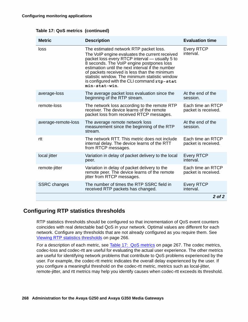
Configuring monitoring applications
268 Administration for the Avaya G250 and Avaya G350 Media Gateways
Configuring RTP statistics thresholds
RTP statistics thresholds should be configured so that incrementation of QoS event counters coincides with real detectable bad QoS in your network. Optimal values are different for each network. Configure any thresholds that are not already configured as you require them. See Viewing RTP statistics thresholds on page 266.For a description of each metric, see Table 17: QoS metrics on page 267. The codec metrics, codec-loss and codec-rtt are useful for evaluating the actual user experience. The other metrics are useful for identifying network problems that contribute to QoS problems experienced by the user. For example, the codec-rtt metric indicates the overall delay experienced by the user. If you configure a meaningful threshold on the codec-rtt metric, metrics such as local-jitter, remote-jitter, and rtt metrics may help you identify causes when codec-rtt exceeds its threshold.
loss The estimated network RTP packet loss.The VoIP engine evaluates the current received packet loss every RTCP interval — usually 5 to 8 seconds. The VoIP engine postpones loss estimation until the next interval if the number of packets received is less than the minimum statistic window. The minimum statistic window is configured with the CLI command rtp-stat min-stat-win.
Every RTCP interval.
average-loss The average packet loss evaluation since the beginning of the RTP stream.
At the end of the session.
remote-loss The network loss according to the remote RTP receiver. The device learns of the remote packet loss from received RTCP messages.
Each time an RTCP packet is received.
average-remote-loss The average remote network loss measurement since the beginning of the RTP stream.
At the end of the session.
rtt The network RTT. This metric does not include internal delay. The device learns of the RTT from RTCP messages.
Each time an RTCP packet is received.
local jitter Variation in delay of packet delivery to the local peer.
Every RTCP interval.
remote-jitter Variation in delay of packet delivery to the remote peer. The device learns of the remote jitter from RTCP messages.
Each time an RTCP packet is received.
SSRC changes The number of times the RTP SSRC field in received RTP packets has changed.
Every RTCP interval.
Table 17: QoS metrics (continued)
Metric Description Evaluation time
2 of 2
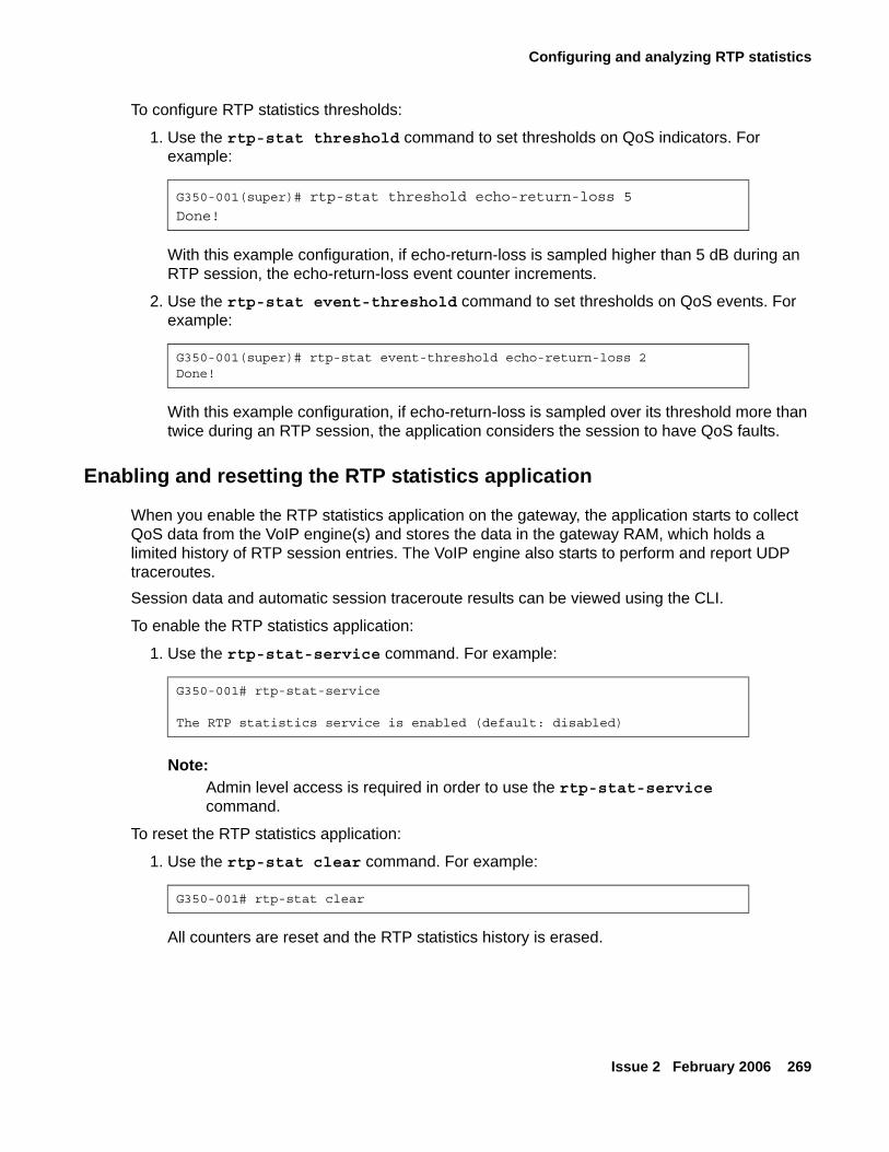
Configuring and analyzing RTP statistics
Issue 2 February 2006 269
To configure RTP statistics thresholds:
1. Use the rtp-stat threshold command to set thresholds on QoS indicators. For example:
With this example configuration, if echo-return-loss is sampled higher than 5 dB during an RTP session, the echo-return-loss event counter increments.
2. Use the rtp-stat event-threshold command to set thresholds on QoS events. For example:
With this example configuration, if echo-return-loss is sampled over its threshold more than twice during an RTP session, the application considers the session to have QoS faults.
Enabling and resetting the RTP statistics application
When you enable the RTP statistics application on the gateway, the application starts to collect QoS data from the VoIP engine(s) and stores the data in the gateway RAM, which holds a limited history of RTP session entries. The VoIP engine also starts to perform and report UDP traceroutes.Session data and automatic session traceroute results can be viewed using the CLI.
To enable the RTP statistics application:
1. Use the rtp-stat-service command. For example:
Note:Note: Admin level access is required in order to use the rtp-stat-service
command.
To reset the RTP statistics application:
1. Use the rtp-stat clear command. For example:
All counters are reset and the RTP statistics history is erased.
G350-001(super)# rtp-stat threshold echo-return-loss 5
Done!
G350-001(super)# rtp-stat event-threshold echo-return-loss 2Done!
G350-001# rtp-stat-service
The RTP statistics service is enabled (default: disabled)
G350-001# rtp-stat clear
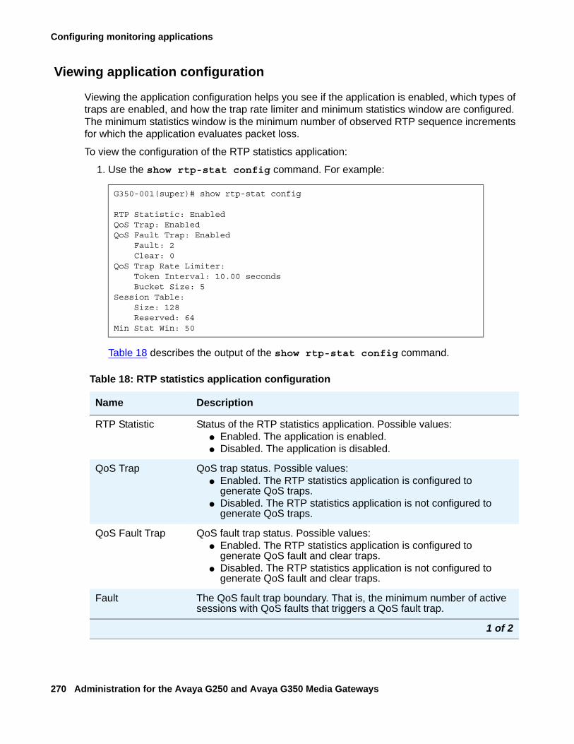
Configuring monitoring applications
270 Administration for the Avaya G250 and Avaya G350 Media Gateways
Viewing application configuration
Viewing the application configuration helps you see if the application is enabled, which types of traps are enabled, and how the trap rate limiter and minimum statistics window are configured. The minimum statistics window is the minimum number of observed RTP sequence increments for which the application evaluates packet loss.
To view the configuration of the RTP statistics application:
1. Use the show rtp-stat config command. For example:
Table 18 describes the output of the show rtp-stat config command.
G350-001(super)# show rtp-stat config
RTP Statistic: EnabledQoS Trap: EnabledQoS Fault Trap: Enabled Fault: 2 Clear: 0QoS Trap Rate Limiter: Token Interval: 10.00 seconds Bucket Size: 5Session Table: Size: 128 Reserved: 64Min Stat Win: 50
Table 18: RTP statistics application configuration
Name Description
RTP Statistic Status of the RTP statistics application. Possible values:● Enabled. The application is enabled.● Disabled. The application is disabled.
QoS Trap QoS trap status. Possible values:● Enabled. The RTP statistics application is configured to
generate QoS traps.● Disabled. The RTP statistics application is not configured to
generate QoS traps.
QoS Fault Trap QoS fault trap status. Possible values:● Enabled. The RTP statistics application is configured to
generate QoS fault and clear traps.● Disabled. The RTP statistics application is not configured to
generate QoS fault and clear traps.
Fault The QoS fault trap boundary. That is, the minimum number of active sessions with QoS faults that triggers a QoS fault trap.
1 of 2
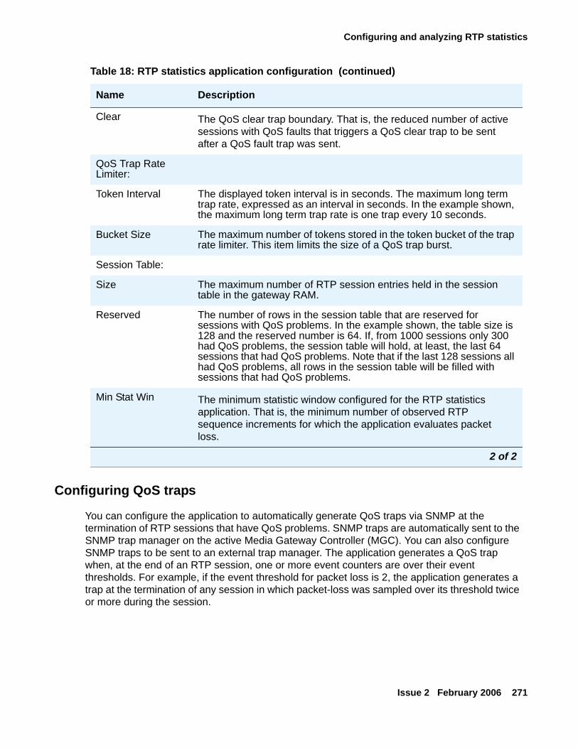
Configuring and analyzing RTP statistics
Issue 2 February 2006 271
Configuring QoS traps
You can configure the application to automatically generate QoS traps via SNMP at the termination of RTP sessions that have QoS problems. SNMP traps are automatically sent to the SNMP trap manager on the active Media Gateway Controller (MGC). You can also configure SNMP traps to be sent to an external trap manager. The application generates a QoS trap when, at the end of an RTP session, one or more event counters are over their event thresholds. For example, if the event threshold for packet loss is 2, the application generates a trap at the termination of any session in which packet-loss was sampled over its threshold twice or more during the session.
Clear The QoS clear trap boundary. That is, the reduced number of active sessions with QoS faults that triggers a QoS clear trap to be sent after a QoS fault trap was sent.
QoS Trap Rate Limiter:
Token Interval The displayed token interval is in seconds. The maximum long term trap rate, expressed as an interval in seconds. In the example shown, the maximum long term trap rate is one trap every 10 seconds.
Bucket Size The maximum number of tokens stored in the token bucket of the trap rate limiter. This item limits the size of a QoS trap burst.
Session Table:
Size The maximum number of RTP session entries held in the session table in the gateway RAM.
Reserved The number of rows in the session table that are reserved for sessions with QoS problems. In the example shown, the table size is 128 and the reserved number is 64. If, from 1000 sessions only 300 had QoS problems, the session table will hold, at least, the last 64 sessions that had QoS problems. Note that if the last 128 sessions all had QoS problems, all rows in the session table will be filled with sessions that had QoS problems.
Min Stat Win The minimum statistic window configured for the RTP statistics application. That is, the minimum number of observed RTP sequence increments for which the application evaluates packet loss.
Table 18: RTP statistics application configuration (continued)
Name Description
2 of 2
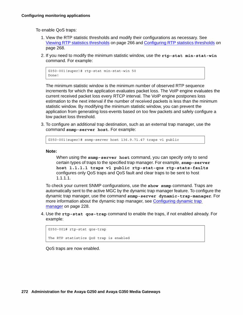
Configuring monitoring applications
272 Administration for the Avaya G250 and Avaya G350 Media Gateways
To enable QoS traps:
1. View the RTP statistic thresholds and modify their configurations as necessary. See Viewing RTP statistics thresholds on page 266 and Configuring RTP statistics thresholds on page 268.
2. If you need to modify the minimum statistic window, use the rtp-stat min-stat-win command. For example:
The minimum statistic window is the minimum number of observed RTP sequence increments for which the application evaluates packet loss. The VoIP engine evaluates the current received packet loss every RTCP interval. The VoIP engine postpones loss estimation to the next interval if the number of received packets is less than the minimum statistic window. By modifying the minimum statistic window, you can prevent the application from generating loss-events based on too few packets and safely configure a low packet loss threshold.
3. To configure an additional trap destination, such as an external trap manager, use the command snmp-server host. For example:
Note:Note: When using the snmp-server host command, you can specify only to send
certain types of traps to the specified trap manager. For example, snmp-server host 1.1.1.1 traps v1 public rtp-stat-qos rtp-stats-faults configures only QoS traps and QoS fault and clear traps to be sent to host 1.1.1.1.
To check your current SNMP configurations, use the show snmp command. Traps are automatically sent to the active MGC by the dynamic trap manager feature. To configure the dynamic trap manager, use the command snmp-server dynamic-trap-manager. For more information about the dynamic trap manager, see Configuring dynamic trap manager on page 228.
4. Use the rtp-stat qos-trap command to enable the traps, if not enabled already. For example:
QoS traps are now enabled.
G350-001(super)# rtp-stat min-stat-win 50Done!
G350-001(super)# snmp-server host 136.9.71.47 traps v1 public
G350-001# rtp-stat qos-trap
The RTP statistics QoS trap is enabled
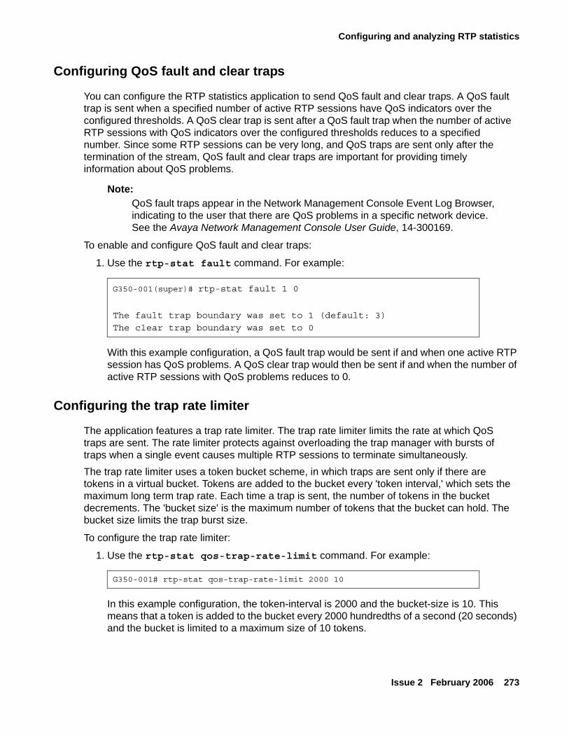
Configuring and analyzing RTP statistics
Issue 2 February 2006 273
Configuring QoS fault and clear traps
You can configure the RTP statistics application to send QoS fault and clear traps. A QoS fault trap is sent when a specified number of active RTP sessions have QoS indicators over the configured thresholds. A QoS clear trap is sent after a QoS fault trap when the number of active RTP sessions with QoS indicators over the configured thresholds reduces to a specified number. Since some RTP sessions can be very long, and QoS traps are sent only after the termination of the stream, QoS fault and clear traps are important for providing timely information about QoS problems.
Note:Note: QoS fault traps appear in the Network Management Console Event Log Browser,
indicating to the user that there are QoS problems in a specific network device. See the Avaya Network Management Console User Guide, 14-300169.
To enable and configure QoS fault and clear traps:
1. Use the rtp-stat fault command. For example:
With this example configuration, a QoS fault trap would be sent if and when one active RTP session has QoS problems. A QoS clear trap would then be sent if and when the number of active RTP sessions with QoS problems reduces to 0.
Configuring the trap rate limiter
The application features a trap rate limiter. The trap rate limiter limits the rate at which QoS traps are sent. The rate limiter protects against overloading the trap manager with bursts of traps when a single event causes multiple RTP sessions to terminate simultaneously.The trap rate limiter uses a token bucket scheme, in which traps are sent only if there are tokens in a virtual bucket. Tokens are added to the bucket every 'token interval,' which sets the maximum long term trap rate. Each time a trap is sent, the number of tokens in the bucket decrements. The 'bucket size' is the maximum number of tokens that the bucket can hold. The bucket size limits the trap burst size.
To configure the trap rate limiter:
1. Use the rtp-stat qos-trap-rate-limit command. For example:
In this example configuration, the token-interval is 2000 and the bucket-size is 10. This means that a token is added to the bucket every 2000 hundredths of a second (20 seconds) and the bucket is limited to a maximum size of 10 tokens.
G350-001(super)# rtp-stat fault 1 0
The fault trap boundary was set to 1 (default: 3)
The clear trap boundary was set to 0
G350-001# rtp-stat qos-trap-rate-limit 2000 10
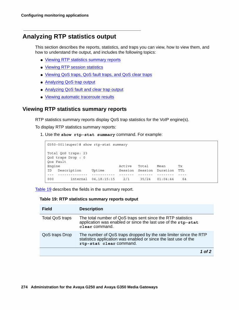
Configuring monitoring applications
274 Administration for the Avaya G250 and Avaya G350 Media Gateways
Analyzing RTP statistics outputThis section describes the reports, statistics, and traps you can view, how to view them, and how to understand the output, and includes the following topics:
● Viewing RTP statistics summary reports
● Viewing RTP session statistics
● Viewing QoS traps, QoS fault traps, and QoS clear traps
● Analyzing QoS trap output
● Analyzing QoS fault and clear trap output
● Viewing automatic traceroute results
Viewing RTP statistics summary reports
RTP statistics summary reports display QoS trap statistics for the VoIP engine(s).
To display RTP statistics summary reports:
1. Use the show rtp-stat summary command. For example:
Table 19 describes the fields in the summary report.
G350-001(super)# show rtp-stat summary
Total QoS traps: 23QoS traps Drop : 0Qos FaultEngine Active Total Mean TxID Description Uptime Session Session Duration TTL--- -------------- ----------- ------- ------- -------- ----000 internal 04,18:15:15 2/1 35/24 01:04:44 64
Table 19: RTP statistics summary reports output
Field Description
Total QoS traps The total number of QoS traps sent since the RTP statistics application was enabled or since the last use of the rtp-stat clear command.
QoS traps Drop The number of QoS traps dropped by the rate limiter since the RTP statistics application was enabled or since the last use of the rtp-stat clear command.
1 of 2
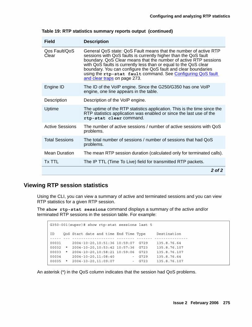
Configuring and analyzing RTP statistics
Issue 2 February 2006 275
Viewing RTP session statistics
Using the CLI, you can view a summary of active and terminated sessions and you can view RTP statistics for a given RTP session. The show rtp-stat sessions command displays a summary of the active and/or terminated RTP sessions in the session table. For example:
An asterisk (*) in the QoS column indicates that the session had QoS problems.
Qos Fault/QoS Clear
General QoS state: QoS Fault means that the number of active RTP sessions with QoS faults is currently higher than the QoS fault boundary. QoS Clear means that the number of active RTP sessions with QoS faults is currently less than or equal to the QoS clear boundary. You can configure the QoS fault and clear boundaries using the rtp-stat fault command. See Configuring QoS fault and clear traps on page 273.
Engine ID The ID of the VoIP engine. Since the G250/G350 has one VoIP engine, one line appears in the table.
Description Description of the VoIP engine.
Uptime The uptime of the RTP statistics application. This is the time since the RTP statistics application was enabled or since the last use of the rtp-stat clear command.
Active Sessions The number of active sessions / number of active sessions with QoS problems.
Total Sessions The total number of sessions / number of sessions that had QoS problems.
Mean Duration The mean RTP session duration (calculated only for terminated calls).
Tx TTL The IP TTL (Time To Live) field for transmitted RTP packets.
Table 19: RTP statistics summary reports output (continued)
Field Description
2 of 2
G350-001(super)# show rtp-stat sessions last 5
ID QoS Start date and time End Time Type Destination----- --- ------------------- -------- ------- ---------------00031 2004-10-20,10:51:36 10:59:07 G729 135.8.76.6400032 * 2004-10-20,10:53:42 10:57:36 G723 135.8.76.10700033 * 2004-10-20,10:58:21 10:59:06 G723 135.8.76.10700034 2004-10-20,11:08:40 - G729 135.8.76.6400035 * 2004-10-20,11:09:07 - G723 135.8.76.107
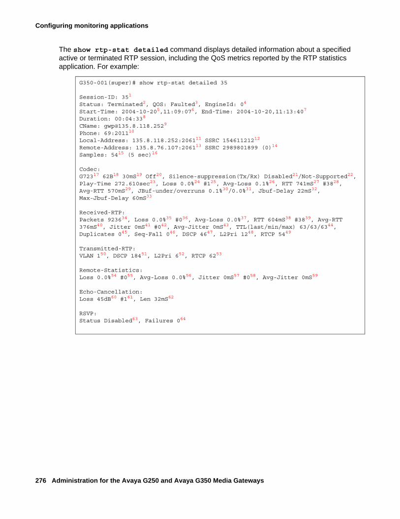
Configuring monitoring applications
276 Administration for the Avaya G250 and Avaya G350 Media Gateways
The show rtp-stat detailed command displays detailed information about a specified active or terminated RTP session, including the QoS metrics reported by the RTP statistics application. For example:
G350-001(super)# show rtp-stat detailed 35
Session-ID: 351
Status: Terminated2, QOS: Faulted3, EngineId: 04
Start-Time: 2004-10-205,11:09:076, End-Time: 2004-10-20,11:13:407
Duration: 00:04:338
CName: [email protected]
Phone: 69:201110
Local-Address: 135.8.118.252:206111 SSRC 15461121212
Remote-Address: 135.8.76.107:206113 SSRC 2989801899 (0)14
Samples: 5415 (5 sec)16
Codec:G72317 62B18 30mS19 Off20, Silence-suppression(Tx/Rx) Disabled21/Not-Supported22, Play-Time 272.610sec23, Loss 0.0%24 #125, Avg-Loss 0.1%26, RTT 741mS27 #3828, Avg-RTT 570mS29, JBuf-under/overruns 0.1%30/0.0%31, Jbuf-Delay 22mS32, Max-Jbuf-Delay 60mS33
Received-RTP:Packets 923634, Loss 0.0%35 #036, Avg-Loss 0.0%37, RTT 604mS38 #3839, Avg-RTT 376mS40, Jitter 0mS41 #042, Avg-Jitter 0mS43, TTL(last/min/max) 63/63/6344, Duplicates 045, Seq-Fall 046, DSCP 4647, L2Pri 1248, RTCP 5449
Transmitted-RTP:VLAN 150, DSCP 18451, L2Pri 652, RTCP 6253
Remote-Statistics:Loss 0.0%54 #055, Avg-Loss 0.0%56, Jitter 0mS57 #058, Avg-Jitter 0mS59
Echo-Cancellation:Loss 45dB60 #161, Len 32mS62
RSVP:Status Disabled63, Failures 064
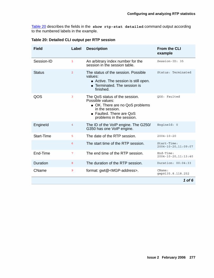
Configuring and analyzing RTP statistics
Issue 2 February 2006 277
Table 20 describes the fields in the show rtp-stat detailed command output according to the numbered labels in the example.
Table 20: Detailed CLI output per RTP session
Field Label Description From the CLI example
Session-ID 1 An arbitrary index number for the session in the session table.
Session-ID: 35
Status 2 The status of the session. Possible values:
● Active. The session is still open.● Terminated. The session is
finished.
Status: Terminated
QOS 3 The QoS status of the session. Possible values:
● OK. There are no QoS problems in the session.
● Faulted. There are QoS problems in the session.
QOS: Faulted
EngineId 4 The ID of the VoIP engine. The G250/G350 has one VoIP engine.
EngineId: 0
Start-Time 5 The date of the RTP session. 2004-10-20
6 The start time of the RTP session. Start-Time: 2004-10-20,11:09:07
End-Time 7 The end time of the RTP session. End-Time: 2004-10-20,11:13:40
Duration 8 The duration of the RTP session. Duration: 00:04:33
CName 9 format: gwt@<MGP-address>. CName: [email protected]
1 of 6
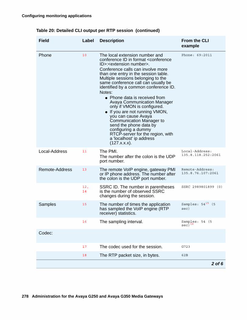
Configuring monitoring applications
278 Administration for the Avaya G250 and Avaya G350 Media Gateways
Phone 10 The local extension number and conference ID in format <conference ID>:<extension number>. Conference calls can involve more than one entry in the session table. Multiple sessions belonging to the same conference call can usually be identified by a common conference ID. Notes:
● Phone data is received from Avaya Communication Manager only if VMON is configured.
● If you are not running VMON, you can cause Avaya Communication Manager to send the phone data by configuring a dummy RTCP-server for the region, with a 'localhost' ip address (127.x.x.x).
Phone: 69:2011
Local-Address 11 The PMI.The number after the colon is the UDP port number.
Local-Address: 135.8.118.252:2061
Remote-Address 13 The remote VoIP engine, gateway PMI or IP phone address. The number after the colon is the UDP port number.
Remote-Address: 135.8.76.107:2061
12, 14
SSRC ID. The number in parentheses is the number of observed SSRC changes during the session.
SSRC 2989801899 (0)
Samples 15 The number of times the application has sampled the VoIP engine (RTP receiver) statistics.
Samples: 5415 (5 sec)
16 The sampling interval. Samples: 54 (5 sec)16
Codec:
17 The codec used for the session. G723
18 The RTP packet size, in bytes. 62B
Table 20: Detailed CLI output per RTP session (continued)
Field Label Description From the CLI example
2 of 6
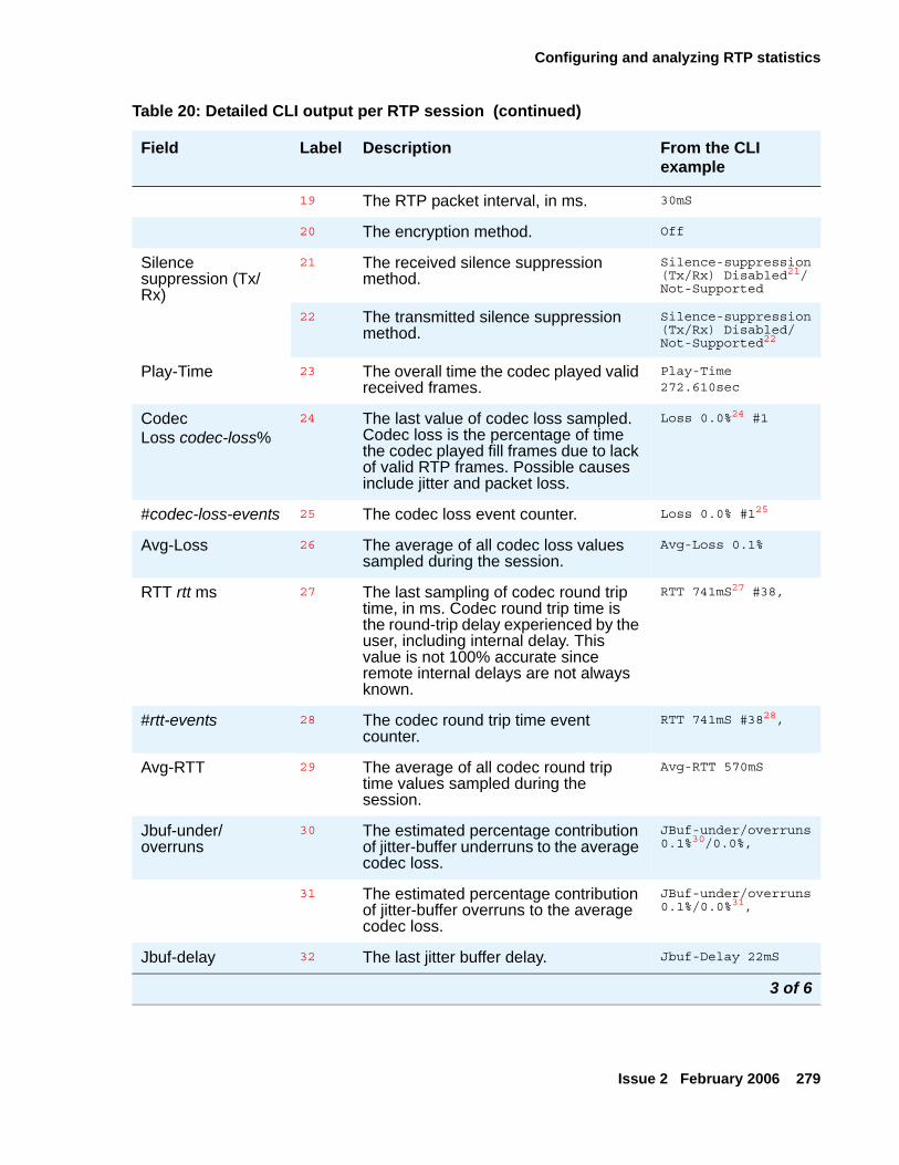
Configuring and analyzing RTP statistics
Issue 2 February 2006 279
19 The RTP packet interval, in ms. 30mS
20 The encryption method. Off
Silence suppression (Tx/Rx)
21 The received silence suppression method.
Silence-suppression(Tx/Rx) Disabled21/Not-Supported
22 The transmitted silence suppression method.
Silence-suppression(Tx/Rx) Disabled/Not-Supported22
Play-Time 23 The overall time the codec played valid received frames.
Play-Time 272.610sec
CodecLoss codec-loss%
24 The last value of codec loss sampled. Codec loss is the percentage of time the codec played fill frames due to lack of valid RTP frames. Possible causes include jitter and packet loss.
Loss 0.0%24 #1
#codec-loss-events 25 The codec loss event counter. Loss 0.0% #125
Avg-Loss 26 The average of all codec loss values sampled during the session.
Avg-Loss 0.1%
RTT rtt ms 27 The last sampling of codec round trip time, in ms. Codec round trip time is the round-trip delay experienced by the user, including internal delay. This value is not 100% accurate since remote internal delays are not always known.
RTT 741mS27 #38,
#rtt-events 28 The codec round trip time event counter.
RTT 741mS #3828,
Avg-RTT 29 The average of all codec round trip time values sampled during the session.
Avg-RTT 570mS
Jbuf-under/overruns
30 The estimated percentage contribution of jitter-buffer underruns to the average codec loss.
JBuf-under/overruns 0.1%30/0.0%,
31 The estimated percentage contribution of jitter-buffer overruns to the average codec loss.
JBuf-under/overruns 0.1%/0.0%31,
Jbuf-delay 32 The last jitter buffer delay. Jbuf-Delay 22mS
Table 20: Detailed CLI output per RTP session (continued)
Field Label Description From the CLI example
3 of 6
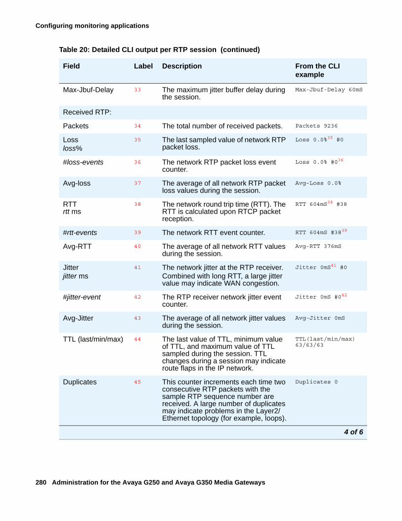
Configuring monitoring applications
280 Administration for the Avaya G250 and Avaya G350 Media Gateways
Max-Jbuf-Delay 33 The maximum jitter buffer delay during the session.
Max-Jbuf-Delay 60mS
Received RTP:
Packets 34 The total number of received packets. Packets 9236
Lossloss%
35 The last sampled value of network RTP packet loss.
Loss 0.0%35 #0
#loss-events 36 The network RTP packet loss event counter.
Loss 0.0% #036
Avg-loss 37 The average of all network RTP packet loss values during the session.
Avg-Loss 0.0%
RTTrtt ms
38 The network round trip time (RTT). The RTT is calculated upon RTCP packet reception.
RTT 604mS38 #38
#rtt-events 39 The network RTT event counter. RTT 604mS #3839
Avg-RTT 40 The average of all network RTT values during the session.
Avg-RTT 376mS
Jitterjitter ms
41 The network jitter at the RTP receiver.Combined with long RTT, a large jitter value may indicate WAN congestion.
Jitter 0mS41 #0
#jitter-event 42 The RTP receiver network jitter event counter.
Jitter 0mS #042
Avg-Jitter 43 The average of all network jitter values during the session.
Avg-Jitter 0mS
TTL (last/min/max) 44 The last value of TTL, minimum value of TTL, and maximum value of TTL sampled during the session. TTL changes during a session may indicate route flaps in the IP network.
TTL(last/min/max) 63/63/63
Duplicates 45 This counter increments each time two consecutive RTP packets with the sample RTP sequence number are received. A large number of duplicates may indicate problems in the Layer2/Ethernet topology (for example, loops).
Duplicates 0
Table 20: Detailed CLI output per RTP session (continued)
Field Label Description From the CLI example
4 of 6
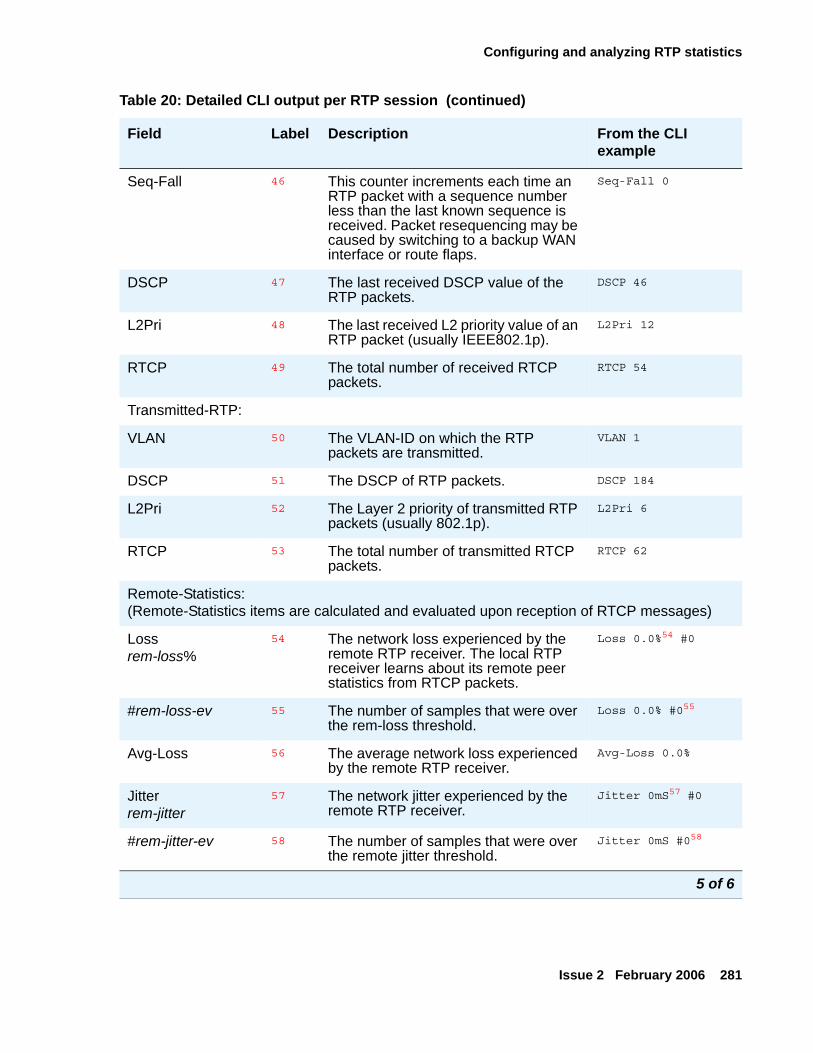
Configuring and analyzing RTP statistics
Issue 2 February 2006 281
Seq-Fall 46 This counter increments each time an RTP packet with a sequence number less than the last known sequence is received. Packet resequencing may be caused by switching to a backup WAN interface or route flaps.
Seq-Fall 0
DSCP 47 The last received DSCP value of the RTP packets.
DSCP 46
L2Pri 48 The last received L2 priority value of an RTP packet (usually IEEE802.1p).
L2Pri 12
RTCP 49 The total number of received RTCP packets.
RTCP 54
Transmitted-RTP:
VLAN 50 The VLAN-ID on which the RTP packets are transmitted.
VLAN 1
DSCP 51 The DSCP of RTP packets. DSCP 184
L2Pri 52 The Layer 2 priority of transmitted RTP packets (usually 802.1p).
L2Pri 6
RTCP 53 The total number of transmitted RTCP packets.
RTCP 62
Remote-Statistics:(Remote-Statistics items are calculated and evaluated upon reception of RTCP messages)
Lossrem-loss%
54 The network loss experienced by the remote RTP receiver. The local RTP receiver learns about its remote peer statistics from RTCP packets.
Loss 0.0%54 #0
#rem-loss-ev 55 The number of samples that were over the rem-loss threshold.
Loss 0.0% #055
Avg-Loss 56 The average network loss experienced by the remote RTP receiver.
Avg-Loss 0.0%
Jitterrem-jitter
57 The network jitter experienced by the remote RTP receiver.
Jitter 0mS57 #0
#rem-jitter-ev 58 The number of samples that were over the remote jitter threshold.
Jitter 0mS #058
Table 20: Detailed CLI output per RTP session (continued)
Field Label Description From the CLI example
5 of 6
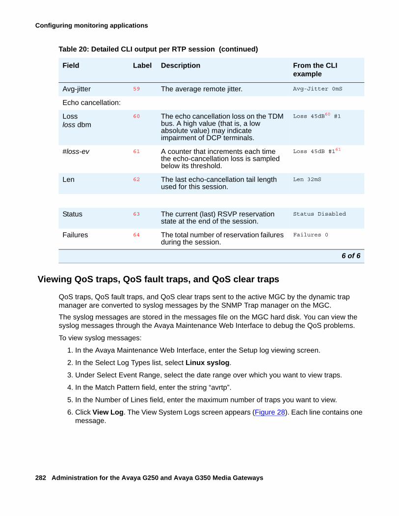
Configuring monitoring applications
282 Administration for the Avaya G250 and Avaya G350 Media Gateways
Viewing QoS traps, QoS fault traps, and QoS clear traps
QoS traps, QoS fault traps, and QoS clear traps sent to the active MGC by the dynamic trap manager are converted to syslog messages by the SNMP Trap manager on the MGC. The syslog messages are stored in the messages file on the MGC hard disk. You can view the syslog messages through the Avaya Maintenance Web Interface to debug the QoS problems.
To view syslog messages:
1. In the Avaya Maintenance Web Interface, enter the Setup log viewing screen.
2. In the Select Log Types list, select Linux syslog.
3. Under Select Event Range, select the date range over which you want to view traps.
4. In the Match Pattern field, enter the string “avrtp”.
5. In the Number of Lines field, enter the maximum number of traps you want to view.
6. Click View Log. The View System Logs screen appears (Figure 28). Each line contains one message.
Avg-jitter 59 The average remote jitter. Avg-Jitter 0mS
Echo cancellation:
Lossloss dbm
60 The echo cancellation loss on the TDM bus. A high value (that is, a low absolute value) may indicate impairment of DCP terminals.
Loss 45dB60 #1
#loss-ev 61 A counter that increments each time the echo-cancellation loss is sampled below its threshold.
Loss 45dB #161
Len 62 The last echo-cancellation tail length used for this session.
Len 32mS
Status 63 The current (last) RSVP reservation state at the end of the session.
Status Disabled
Failures 64 The total number of reservation failures during the session.
Failures 0
Table 20: Detailed CLI output per RTP session (continued)
Field Label Description From the CLI example
6 of 6
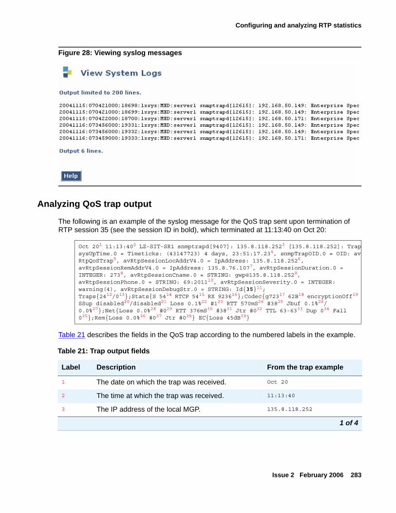
Configuring and analyzing RTP statistics
Issue 2 February 2006 283
Figure 28: Viewing syslog messages
Analyzing QoS trap output
The following is an example of the syslog message for the QoS trap sent upon termination of RTP session 35 (see the session ID in bold), which terminated at 11:13:40 on Oct 20:
Table 21 describes the fields in the QoS trap according to the numbered labels in the example.
Oct 201 11:13:402 LZ-SIT-SR1 snmptrapd[9407]: 135.8.118.2523 [135.8.118.252]: TrapsysUpTime.0 = Timeticks: (43147723) 4 days, 23:51:17.234, snmpTrapOID.0 = OID: avRtpQoSTrap5, avRtpSessionLocAddrV4.0 = IpAddress: 135.8.118.2526, avRtpSessionRemAddrV4.0 = IpAddress: 135.8.76.1077, avRtpSessionDuration.0 = INTEGER: 2738, avRtpSessionCname.0 = STRING: [email protected], avRtpSessionPhone.0 = STRING: 69:201110, avRtpSessionSeverity.0 = INTEGER: warning(4), avRtpSessionDebugStr.0 = STRING: Id{35}11;Traps{2412/013};Stats{S 5414 RTCP 5415 RX 923616};Codec{g72317 62B18 encryptionOff19 SSup disabled20/disabled21 Loss 0.1%22 #123 RTT 570mS24 #3825 Jbuf 0.1%26/0.0%27};Net{Loss 0.0%28 #029 RTT 376mS30 #3831 Jtr #032 TTL 63-6333 Dup 034 Fall 035};Rem{Loss 0.0%36 #037 Jtr #038} EC{Loss 45dB39}
Table 21: Trap output fields
Label Description From the trap example
1 The date on which the trap was received. Oct 20
2 The time at which the trap was received. 11:13:40
3 The IP address of the local MGP. 135.8.118.252
1 of 4
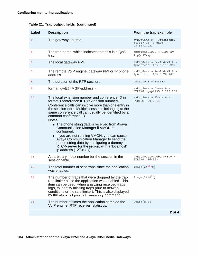
Configuring monitoring applications
284 Administration for the Avaya G250 and Avaya G350 Media Gateways
4 The gateway up time. sysUpTime.0 = Timeticks: (43147723) 4 days, 23:51:17.23
5 The trap name, which indicates that this is a QoS trap.
snmpTrapOID.0 = OID: avRtpQoSTrap
6 The local gateway PMI. avRtpSessionLocAddrV4.0 = IpAddress: 135.8.118.252
7 The remote VoIP engine, gateway PMI or IP phone address.
avRtpSessionRemAddrV4.0 = IpAddress: 135.8.76.107
8 The duration of the RTP session. Duration: 00:04:33
9 format: gwt@<MGP-address>. avRtpSessionCname.0 = STRING: [email protected]
10 The local extension number and conference ID in format <conference ID>:<extension number>. Conference calls can involve more than one entry in the session table. Multiple sessions belonging to the same conference call can usually be identified by a common conference ID. Notes:
● The phone string data is received from Avaya Communication Manager if VMON is configured.
● If you are not running VMON, you can cause Avaya Communication Manager to send the phone string data by configuring a dummy RTCP-server for the region, with a 'localhost' ip address (127.x.x.x).
avRtpSessionPhone.0 = STRING: 69:2011
11 An arbitrary index number for the session in the session table.
avRtpSessionDebugStr.0 = STRING: Id{35}
12 The total number of sent traps since the application was enabled.
Traps{2411/0}
13 The number of traps that were dropped by the trap rate limiter since the application was enabled. This item can be used, when analyzing received traps logs, to identify missing traps (due to network conditions or the rate limiter). This is also displayed by the show rtp-stat summary command.
Traps{24/012}
14 The number of times the application sampled the VoIP engine (RTP receiver) statistics.
Stats{S 54
Table 21: Trap output fields (continued)
Label Description From the trap example
2 of 4
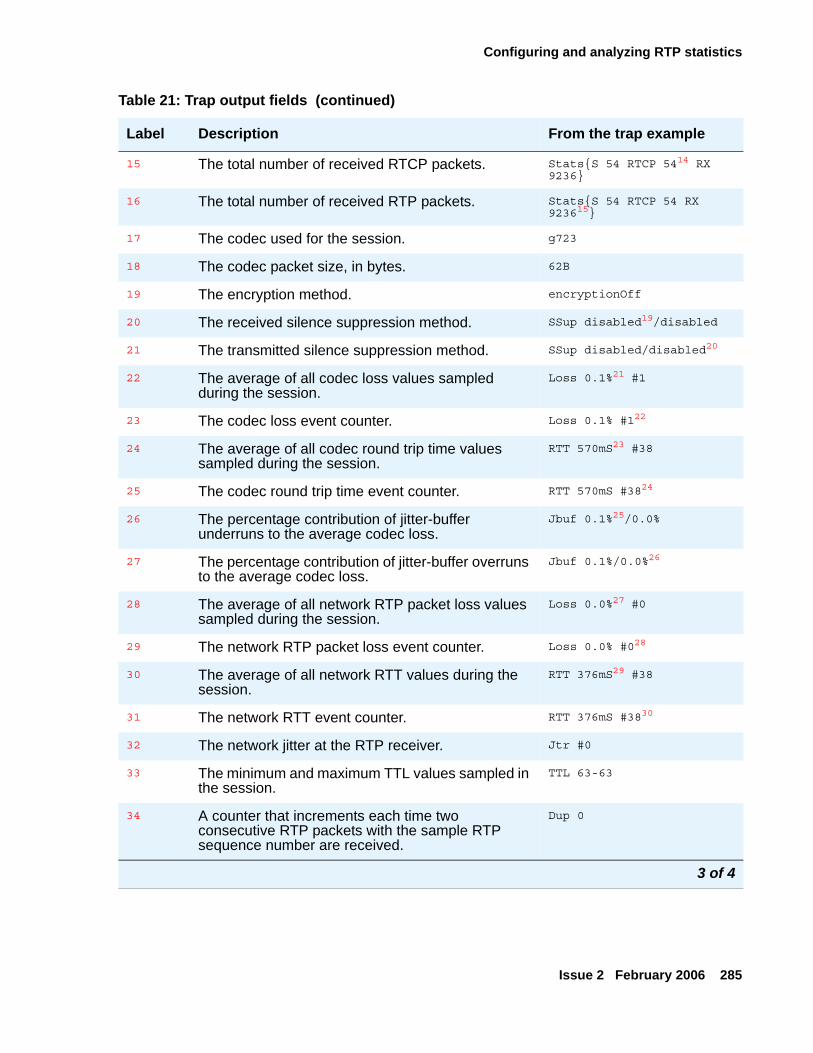
Configuring and analyzing RTP statistics
Issue 2 February 2006 285
15 The total number of received RTCP packets. Stats{S 54 RTCP 5414 RX 9236}
16 The total number of received RTP packets. Stats{S 54 RTCP 54 RX 923615}
17 The codec used for the session. g723
18 The codec packet size, in bytes. 62B
19 The encryption method. encryptionOff
20 The received silence suppression method. SSup disabled19/disabled
21 The transmitted silence suppression method. SSup disabled/disabled20
22 The average of all codec loss values sampled during the session.
Loss 0.1%21 #1
23 The codec loss event counter. Loss 0.1% #122
24 The average of all codec round trip time values sampled during the session.
RTT 570mS23 #38
25 The codec round trip time event counter. RTT 570mS #3824
26 The percentage contribution of jitter-buffer underruns to the average codec loss.
Jbuf 0.1%25/0.0%
27 The percentage contribution of jitter-buffer overruns to the average codec loss.
Jbuf 0.1%/0.0%26
28 The average of all network RTP packet loss values sampled during the session.
Loss 0.0%27 #0
29 The network RTP packet loss event counter. Loss 0.0% #028
30 The average of all network RTT values during the session.
RTT 376mS29 #38
31 The network RTT event counter. RTT 376mS #3830
32 The network jitter at the RTP receiver. Jtr #0
33 The minimum and maximum TTL values sampled in the session.
TTL 63-63
34 A counter that increments each time two consecutive RTP packets with the sample RTP sequence number are received.
Dup 0
Table 21: Trap output fields (continued)
Label Description From the trap example
3 of 4
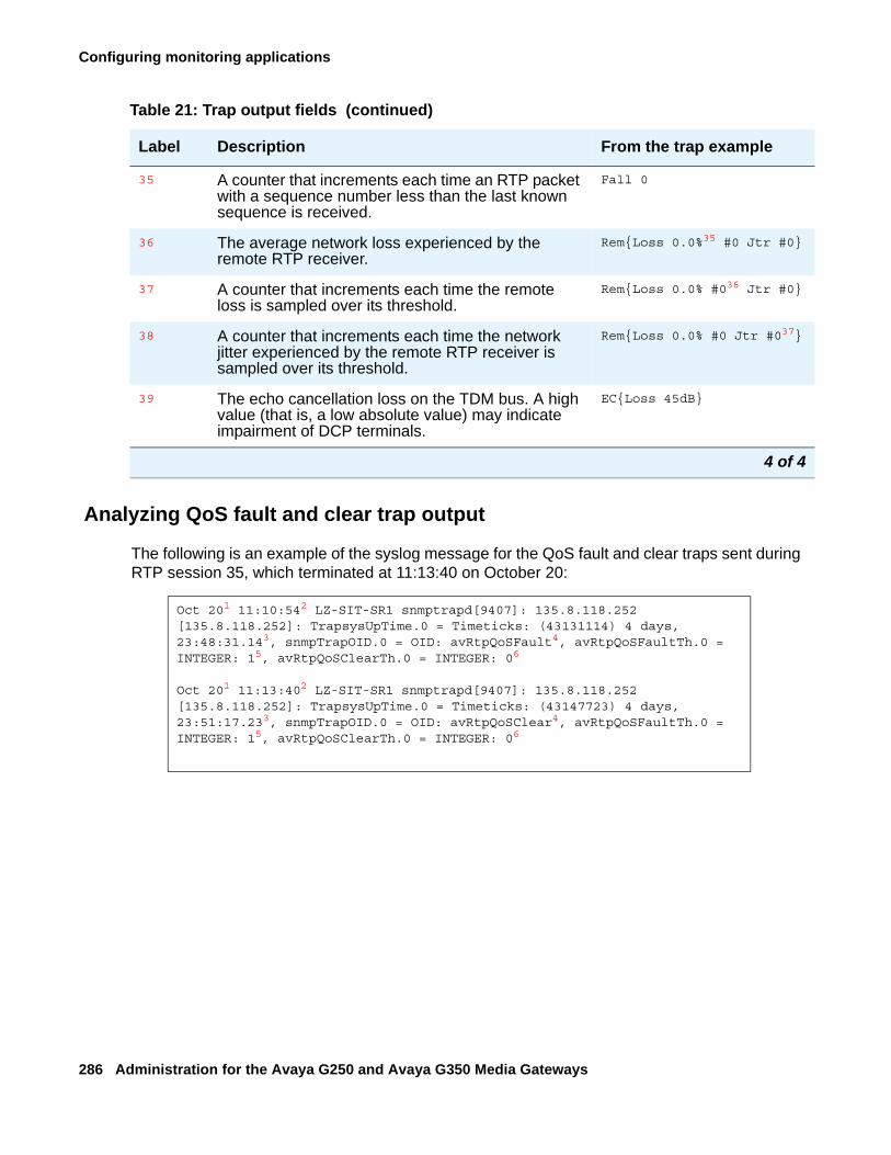
Configuring monitoring applications
286 Administration for the Avaya G250 and Avaya G350 Media Gateways
Analyzing QoS fault and clear trap output
The following is an example of the syslog message for the QoS fault and clear traps sent during RTP session 35, which terminated at 11:13:40 on October 20:
35 A counter that increments each time an RTP packet with a sequence number less than the last known sequence is received.
Fall 0
36 The average network loss experienced by the remote RTP receiver.
Rem{Loss 0.0%35 #0 Jtr #0}
37 A counter that increments each time the remote loss is sampled over its threshold.
Rem{Loss 0.0% #036 Jtr #0}
38 A counter that increments each time the network jitter experienced by the remote RTP receiver is sampled over its threshold.
Rem{Loss 0.0% #0 Jtr #037}
39 The echo cancellation loss on the TDM bus. A high value (that is, a low absolute value) may indicate impairment of DCP terminals.
EC{Loss 45dB}
Table 21: Trap output fields (continued)
Label Description From the trap example
4 of 4
Oct 201 11:10:542 LZ-SIT-SR1 snmptrapd[9407]: 135.8.118.252 [135.8.118.252]: TrapsysUpTime.0 = Timeticks: (43131114) 4 days, 23:48:31.143, snmpTrapOID.0 = OID: avRtpQoSFault4, avRtpQoSFaultTh.0 = INTEGER: 15, avRtpQoSClearTh.0 = INTEGER: 06
Oct 201 11:13:402 LZ-SIT-SR1 snmptrapd[9407]: 135.8.118.252 [135.8.118.252]: TrapsysUpTime.0 = Timeticks: (43147723) 4 days, 23:51:17.233, snmpTrapOID.0 = OID: avRtpQoSClear4, avRtpQoSFaultTh.0 = INTEGER: 15, avRtpQoSClearTh.0 = INTEGER: 06
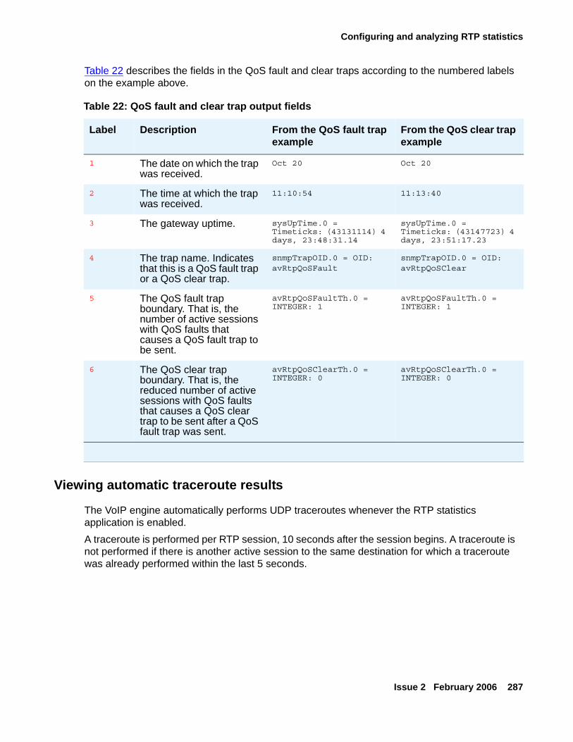
Configuring and analyzing RTP statistics
Issue 2 February 2006 287
Table 22 describes the fields in the QoS fault and clear traps according to the numbered labels on the example above.
Viewing automatic traceroute results
The VoIP engine automatically performs UDP traceroutes whenever the RTP statistics application is enabled.A traceroute is performed per RTP session, 10 seconds after the session begins. A traceroute is not performed if there is another active session to the same destination for which a traceroute was already performed within the last 5 seconds.
Table 22: QoS fault and clear trap output fields
Label Description From the QoS fault trap example
From the QoS clear trap example
1 The date on which the trap was received.
Oct 20 Oct 20
2 The time at which the trap was received.
11:10:54 11:13:40
3 The gateway uptime. sysUpTime.0 = Timeticks: (43131114) 4 days, 23:48:31.14
sysUpTime.0 = Timeticks: (43147723) 4 days, 23:51:17.23
4 The trap name. Indicates that this is a QoS fault trap or a QoS clear trap.
snmpTrapOID.0 = OID: avRtpQoSFault
snmpTrapOID.0 = OID: avRtpQoSClear
5 The QoS fault trap boundary. That is, the number of active sessions with QoS faults that causes a QoS fault trap to be sent.
avRtpQoSFaultTh.0 = INTEGER: 1
avRtpQoSFaultTh.0 = INTEGER: 1
6 The QoS clear trap boundary. That is, the reduced number of active sessions with QoS faults that causes a QoS clear trap to be sent after a QoS fault trap was sent.
avRtpQoSClearTh.0 = INTEGER: 0
avRtpQoSClearTh.0 = INTEGER: 0
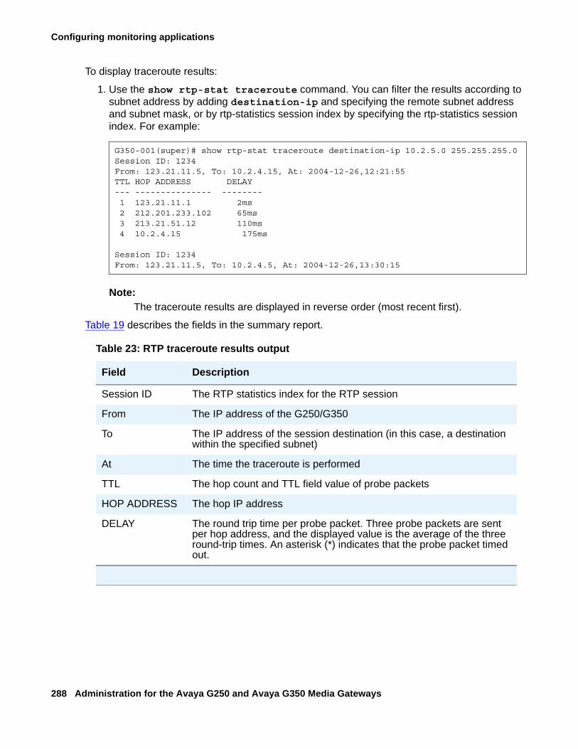
Configuring monitoring applications
288 Administration for the Avaya G250 and Avaya G350 Media Gateways
To display traceroute results:
1. Use the show rtp-stat traceroute command. You can filter the results according to subnet address by adding destination-ip and specifying the remote subnet address and subnet mask, or by rtp-statistics session index by specifying the rtp-statistics session index. For example:
Note:Note: The traceroute results are displayed in reverse order (most recent first).
Table 19 describes the fields in the summary report.
G350-001(super)# show rtp-stat traceroute destination-ip 10.2.5.0 255.255.255.0Session ID: 1234From: 123.21.11.5, To: 10.2.4.15, At: 2004-12-26,12:21:55TTL HOP ADDRESS DELAY --- --------------- -------- 1 123.21.11.1 2ms 2 212.201.233.102 65ms 3 213.21.51.12 110ms 4 10.2.4.15 175ms
Session ID: 1234From: 123.21.11.5, To: 10.2.4.5, At: 2004-12-26,13:30:15
Table 23: RTP traceroute results output
Field Description
Session ID The RTP statistics index for the RTP session
From The IP address of the G250/G350
To The IP address of the session destination (in this case, a destination within the specified subnet)
At The time the traceroute is performed
TTL The hop count and TTL field value of probe packets
HOP ADDRESS The hop IP address
DELAY The round trip time per probe packet. Three probe packets are sent per hop address, and the displayed value is the average of the three round-trip times. An asterisk (*) indicates that the probe packet timed out.
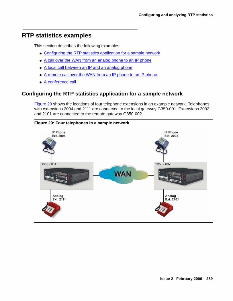
Configuring and analyzing RTP statistics
Issue 2 February 2006 289
RTP statistics examplesThis section describes the following examples:
● Configuring the RTP statistics application for a sample network
● A call over the WAN from an analog phone to an IP phone
● A local call between an IP and an analog phone
● A remote call over the WAN from an IP phone to an IP phone
● A conference call
Configuring the RTP statistics application for a sample network
Figure 29 shows the locations of four telephone extensions in an example network. Telephones with extensions 2004 and 2111 are connected to the local gateway G350-001. Extensions 2002 and 2101 are connected to the remote gateway G350-002.
Figure 29: Four telephones in a sample network
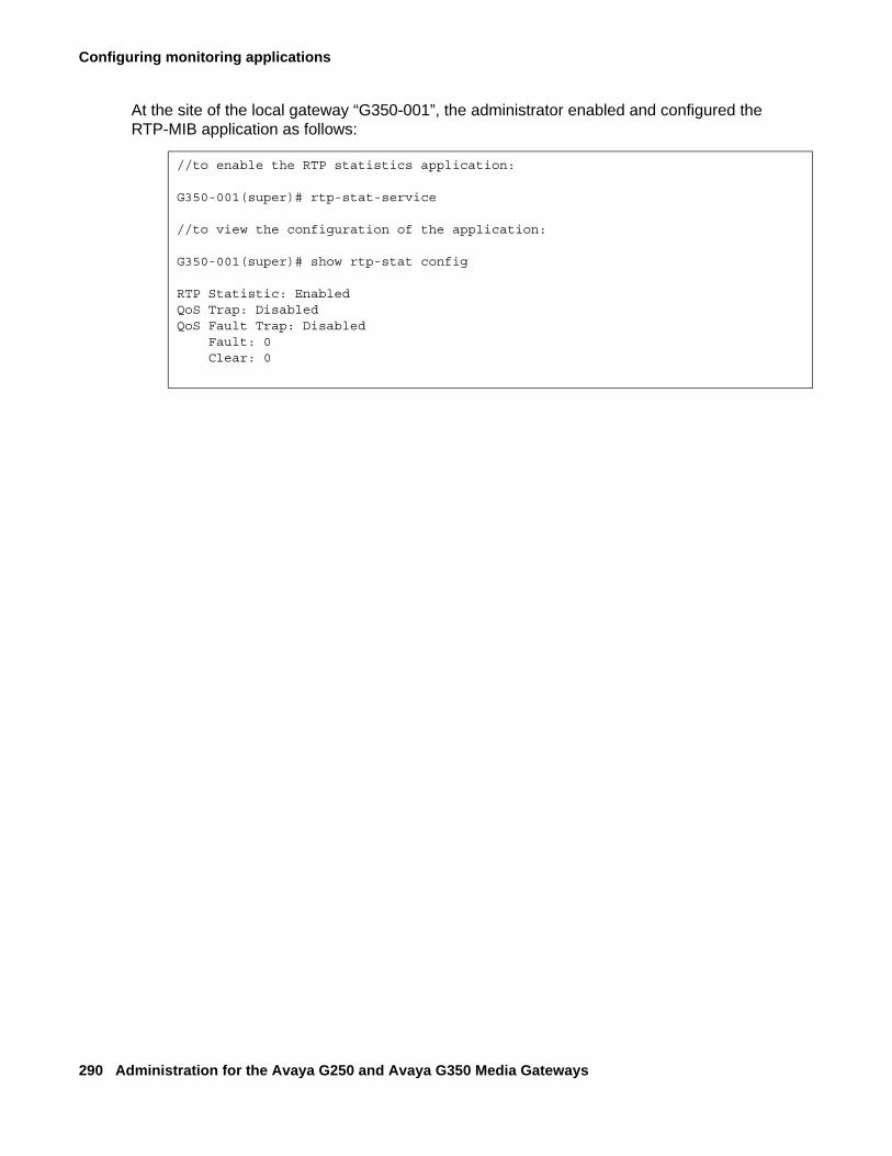
Configuring monitoring applications
290 Administration for the Avaya G250 and Avaya G350 Media Gateways
At the site of the local gateway “G350-001”, the administrator enabled and configured the RTP-MIB application as follows:
//to enable the RTP statistics application:
G350-001(super)# rtp-stat-service
//to view the configuration of the application:
G350-001(super)# show rtp-stat config
RTP Statistic: EnabledQoS Trap: DisabledQoS Fault Trap: Disabled Fault: 0 Clear: 0
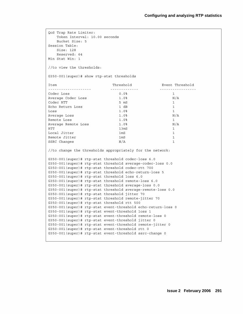
Configuring and analyzing RTP statistics
Issue 2 February 2006 291
QoS Trap Rate Limiter: Token Interval: 10.00 seconds Bucket Size: 5Session Table: Size: 128 Reserved: 64Min Stat Win: 1
//to view the thresholds:
G350-001(super)# show rtp-stat thresholds
Item Threshold Event Threshold-------------------- ------------- -----------------Codec Loss 0.0% 1Average Codec Loss 1.0% N/ACodec RTT 5 mS 1Echo Return Loss 1 dB 1Loss 1.0% 1Average Loss 1.0% N/ARemote Loss 1.0% 1Average Remote Loss 1.0% N/ARTT 13mS 1Local Jitter 1mS 1Remote Jitter 1mS 1SSRC Changes N/A 1
//to change the thresholds appropriately for the network:
G350-001(super)# rtp-stat threshold codec-loss 6.0G350-001(super)# rtp-stat threshold average-codec-loss 0.0G350-001(super)# rtp-stat threshold codec-rtt 700G350-001(super)# rtp-stat threshold echo-return-loss 5G350-001(super)# rtp-stat threshold loss 6.0G350-001(super)# rtp-stat threshold remote-loss 6.0G350-001(super)# rtp-stat threshold average-loss 0.0G350-001(super)# rtp-stat threshold average-remote-loss 0.0G350-001(super)# rtp-stat threshold jitter 70G350-001(super)# rtp-stat threshold remote-jitter 70G350-001(super)# rtp-stat threshold rtt 500G350-001(super)# rtp-stat event-threshold echo-return-loss 0G350-001(super)# rtp-stat event-threshold loss 1G350-001(super)# rtp-stat event-threshold remote-loss 0G350-001(super)# rtp-stat event-threshold jitter 0G350-001(super)# rtp-stat event-threshold remote-jitter 0G350-001(super)# rtp-stat event-threshold rtt 0G350-001(super)# rtp-stat event-threshold ssrc-change 0
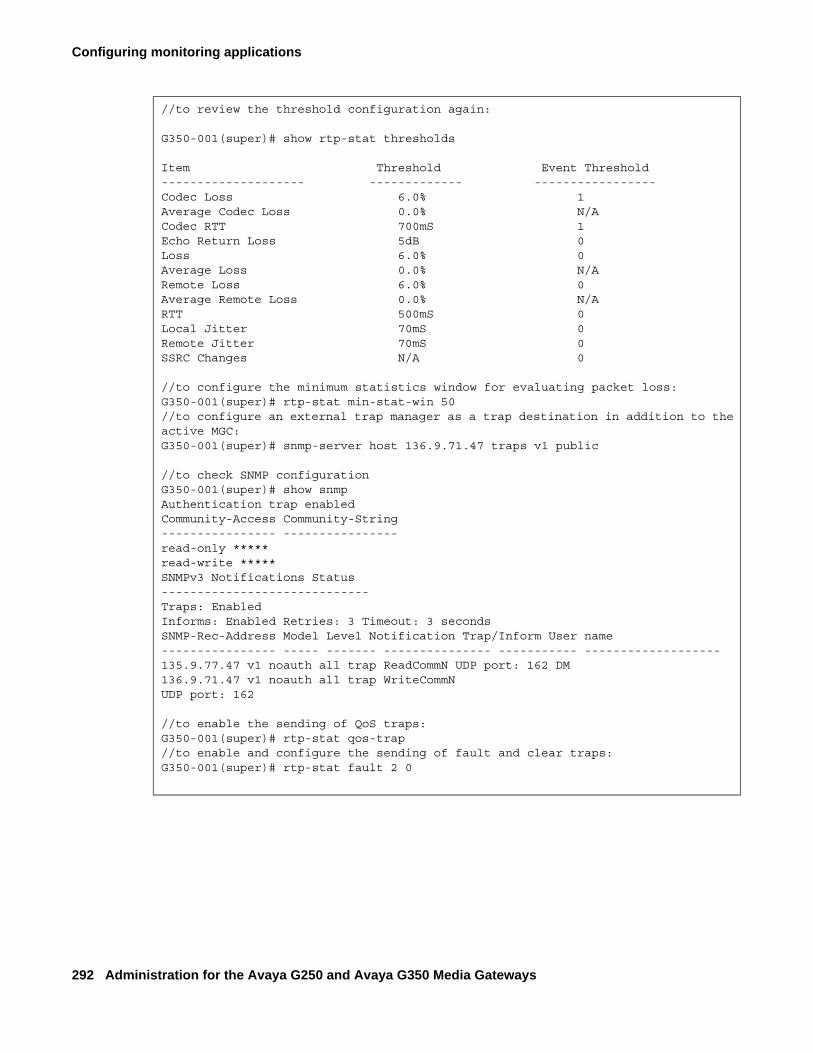
Configuring monitoring applications
292 Administration for the Avaya G250 and Avaya G350 Media Gateways
//to review the threshold configuration again:
G350-001(super)# show rtp-stat thresholds
Item Threshold Event Threshold-------------------- ------------- -----------------Codec Loss 6.0% 1Average Codec Loss 0.0% N/ACodec RTT 700mS 1Echo Return Loss 5dB 0Loss 6.0% 0Average Loss 0.0% N/ARemote Loss 6.0% 0Average Remote Loss 0.0% N/ARTT 500mS 0Local Jitter 70mS 0Remote Jitter 70mS 0SSRC Changes N/A 0
//to configure the minimum statistics window for evaluating packet loss:G350-001(super)# rtp-stat min-stat-win 50//to configure an external trap manager as a trap destination in addition to the active MGC:G350-001(super)# snmp-server host 136.9.71.47 traps v1 public
//to check SNMP configurationG350-001(super)# show snmpAuthentication trap enabledCommunity-Access Community-String---------------- ----------------read-only *****read-write *****SNMPv3 Notifications Status-----------------------------Traps: EnabledInforms: Enabled Retries: 3 Timeout: 3 seconds SNMP-Rec-Address Model Level Notification Trap/Inform User name---------------- ----- ------- --------------- ----------- -------------------135.9.77.47 v1 noauth all trap ReadCommN UDP port: 162 DM 136.9.71.47 v1 noauth all trap WriteCommN UDP port: 162
//to enable the sending of QoS traps:G350-001(super)# rtp-stat qos-trap//to enable and configure the sending of fault and clear traps:G350-001(super)# rtp-stat fault 2 0
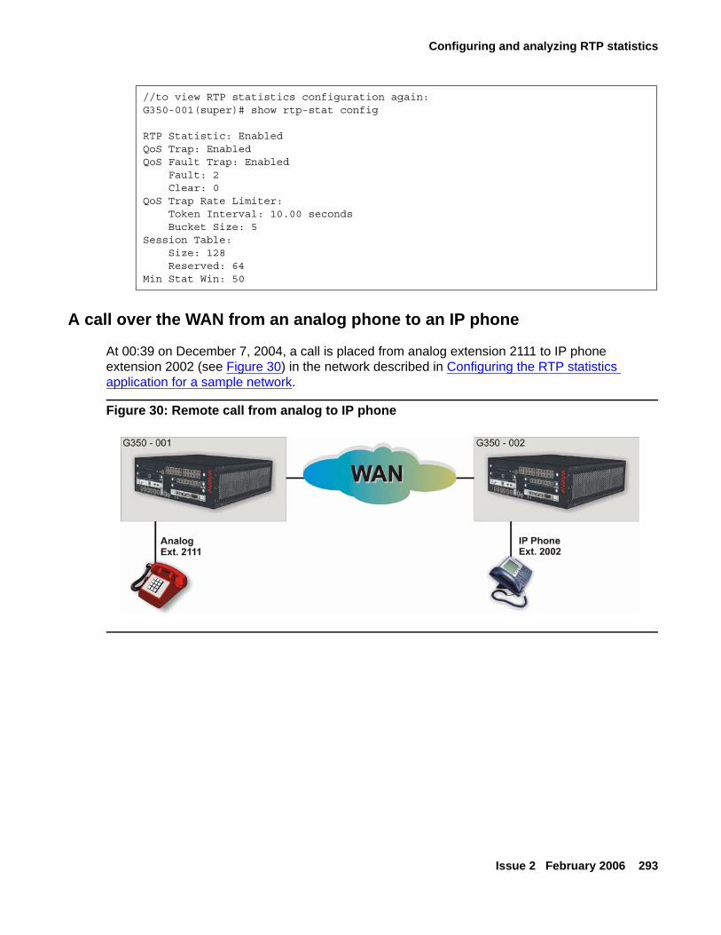
Configuring and analyzing RTP statistics
Issue 2 February 2006 293
A call over the WAN from an analog phone to an IP phone
At 00:39 on December 7, 2004, a call is placed from analog extension 2111 to IP phone extension 2002 (see Figure 30) in the network described in Configuring the RTP statistics application for a sample network.
Figure 30: Remote call from analog to IP phone
//to view RTP statistics configuration again:G350-001(super)# show rtp-stat config
RTP Statistic: EnabledQoS Trap: EnabledQoS Fault Trap: Enabled Fault: 2 Clear: 0QoS Trap Rate Limiter: Token Interval: 10.00 seconds Bucket Size: 5Session Table: Size: 128 Reserved: 64Min Stat Win: 50
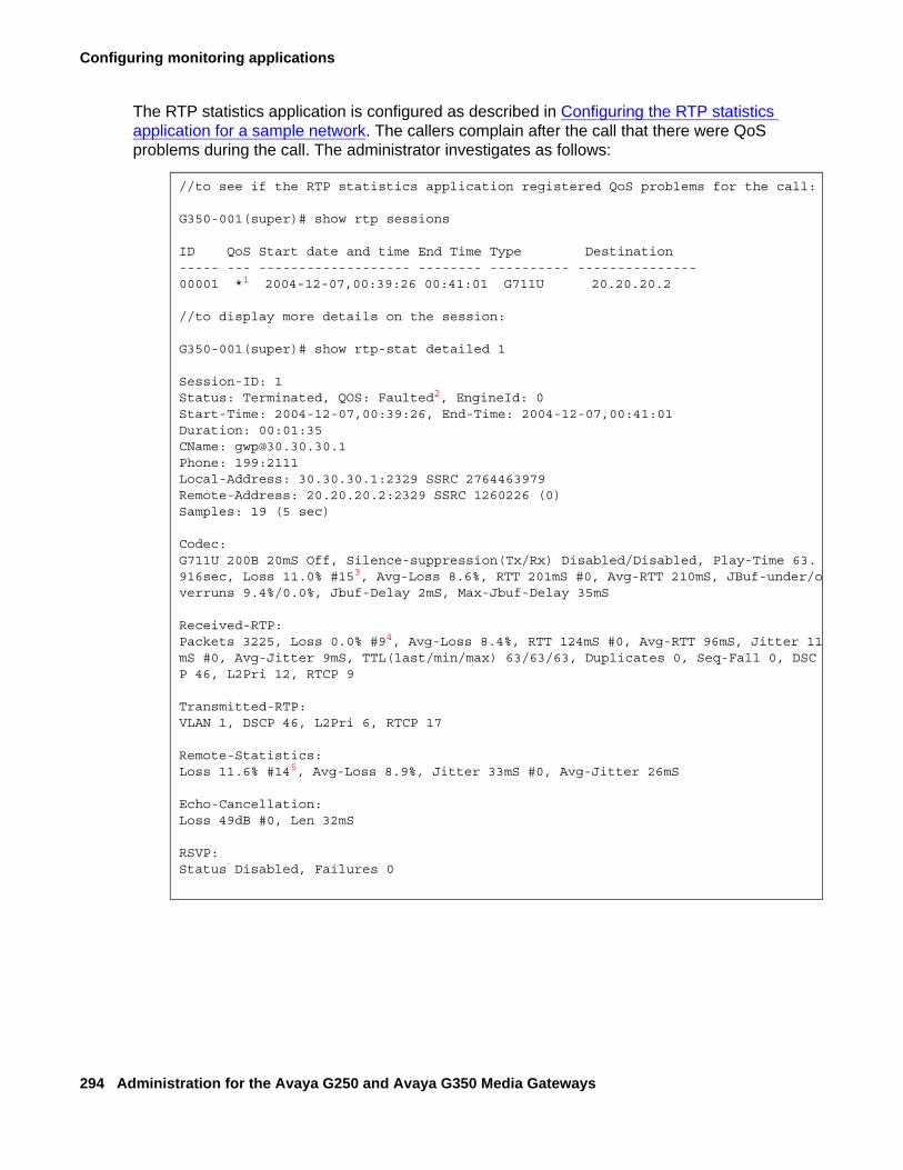
Configuring monitoring applications
294 Administration for the Avaya G250 and Avaya G350 Media Gateways
The RTP statistics application is configured as described in Configuring the RTP statistics application for a sample network. The callers complain after the call that there were QoS problems during the call. The administrator investigates as follows:
//to see if the RTP statistics application registered QoS problems for the call:
G350-001(super)# show rtp sessions
ID QoS Start date and time End Time Type Destination----- --- ------------------- -------- ---------- ---------------00001 *1 2004-12-07,00:39:26 00:41:01 G711U 20.20.20.2
//to display more details on the session:
G350-001(super)# show rtp-stat detailed 1
Session-ID: 1Status: Terminated, QOS: Faulted2, EngineId: 0Start-Time: 2004-12-07,00:39:26, End-Time: 2004-12-07,00:41:01Duration: 00:01:35CName: [email protected]: 199:2111Local-Address: 30.30.30.1:2329 SSRC 2764463979 Remote-Address: 20.20.20.2:2329 SSRC 1260226 (0)Samples: 19 (5 sec)
Codec:G711U 200B 20mS Off, Silence-suppression(Tx/Rx) Disabled/Disabled, Play-Time 63.916sec, Loss 11.0% #153, Avg-Loss 8.6%, RTT 201mS #0, Avg-RTT 210mS, JBuf-under/overruns 9.4%/0.0%, Jbuf-Delay 2mS, Max-Jbuf-Delay 35mS
Received-RTP:Packets 3225, Loss 0.0% #94, Avg-Loss 8.4%, RTT 124mS #0, Avg-RTT 96mS, Jitter 11mS #0, Avg-Jitter 9mS, TTL(last/min/max) 63/63/63, Duplicates 0, Seq-Fall 0, DSCP 46, L2Pri 12, RTCP 9
Transmitted-RTP:VLAN 1, DSCP 46, L2Pri 6, RTCP 17
Remote-Statistics:Loss 11.6% #145, Avg-Loss 8.9%, Jitter 33mS #0, Avg-Jitter 26mS
Echo-Cancellation:Loss 49dB #0, Len 32mS
RSVP:Status Disabled, Failures 0
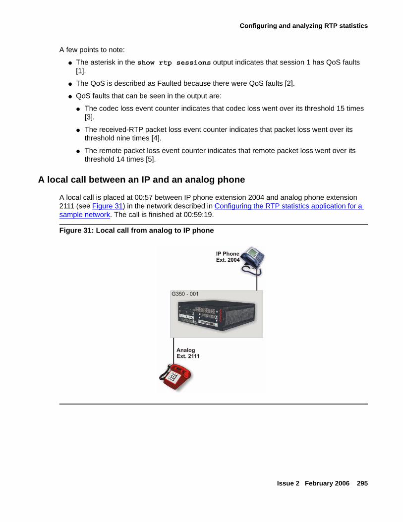
Configuring and analyzing RTP statistics
Issue 2 February 2006 295
A few points to note:
● The asterisk in the show rtp sessions output indicates that session 1 has QoS faults [1].
● The QoS is described as Faulted because there were QoS faults [2].
● QoS faults that can be seen in the output are:
● The codec loss event counter indicates that codec loss went over its threshold 15 times [3].
● The received-RTP packet loss event counter indicates that packet loss went over its threshold nine times [4].
● The remote packet loss event counter indicates that remote packet loss went over its threshold 14 times [5].
A local call between an IP and an analog phone
A local call is placed at 00:57 between IP phone extension 2004 and analog phone extension 2111 (see Figure 31) in the network described in Configuring the RTP statistics application for a sample network. The call is finished at 00:59:19.
Figure 31: Local call from analog to IP phone
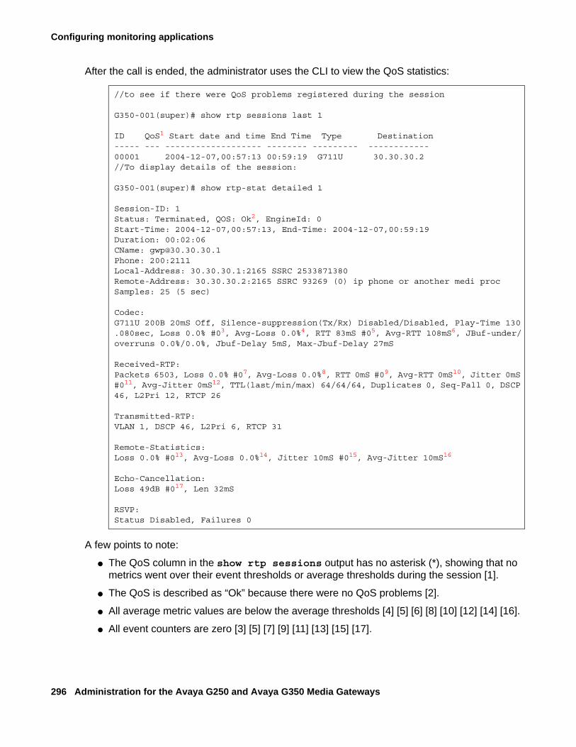
Configuring monitoring applications
296 Administration for the Avaya G250 and Avaya G350 Media Gateways
After the call is ended, the administrator uses the CLI to view the QoS statistics:
A few points to note:
● The QoS column in the show rtp sessions output has no asterisk (*), showing that no metrics went over their event thresholds or average thresholds during the session [1].
● The QoS is described as “Ok” because there were no QoS problems [2].
● All average metric values are below the average thresholds [4] [5] [6] [8] [10] [12] [14] [16].
● All event counters are zero [3] [5] [7] [9] [11] [13] [15] [17].
//to see if there were QoS problems registered during the session
G350-001(super)# show rtp sessions last 1
ID QoS1 Start date and time End Time Type Destination----- --- ------------------- -------- --------- ------------00001 2004-12-07,00:57:13 00:59:19 G711U 30.30.30.2//To display details of the session:
G350-001(super)# show rtp-stat detailed 1
Session-ID: 1Status: Terminated, QOS: Ok2, EngineId: 0Start-Time: 2004-12-07,00:57:13, End-Time: 2004-12-07,00:59:19Duration: 00:02:06CName: [email protected]: 200:2111Local-Address: 30.30.30.1:2165 SSRC 2533871380Remote-Address: 30.30.30.2:2165 SSRC 93269 (0) ip phone or another medi procSamples: 25 (5 sec)
Codec:G711U 200B 20mS Off, Silence-suppression(Tx/Rx) Disabled/Disabled, Play-Time 130.080sec, Loss 0.0% #03, Avg-Loss 0.0%4, RTT 83mS #05, Avg-RTT 108mS6, JBuf-under/overruns 0.0%/0.0%, Jbuf-Delay 5mS, Max-Jbuf-Delay 27mS
Received-RTP:Packets 6503, Loss 0.0% #07, Avg-Loss 0.0%8, RTT 0mS #09, Avg-RTT 0mS10, Jitter 0mS #011, Avg-Jitter 0mS12, TTL(last/min/max) 64/64/64, Duplicates 0, Seq-Fall 0, DSCP 46, L2Pri 12, RTCP 26
Transmitted-RTP:VLAN 1, DSCP 46, L2Pri 6, RTCP 31
Remote-Statistics:Loss 0.0% #013, Avg-Loss 0.0%14, Jitter 10mS #015, Avg-Jitter 10mS16
Echo-Cancellation:Loss 49dB #017, Len 32mS
RSVP:Status Disabled, Failures 0
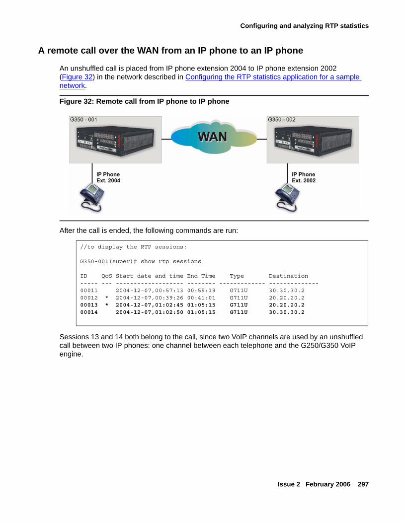
Configuring and analyzing RTP statistics
Issue 2 February 2006 297
A remote call over the WAN from an IP phone to an IP phone
An unshuffled call is placed from IP phone extension 2004 to IP phone extension 2002 (Figure 32) in the network described in Configuring the RTP statistics application for a sample network.
Figure 32: Remote call from IP phone to IP phone
After the call is ended, the following commands are run:
Sessions 13 and 14 both belong to the call, since two VoIP channels are used by an unshuffled call between two IP phones: one channel between each telephone and the G250/G350 VoIP engine.
//to display the RTP sessions:
G350-001(super)# show rtp sessions
ID QoS Start date and time End Time Type Destination----- --- ------------------- -------- ------------- --------------00011 2004-12-07,00:57:13 00:59:19 G711U 30.30.30.200012 * 2004-12-07,00:39:26 00:41:01 G711U 20.20.20.200013 * 2004-12-07,01:02:45 01:05:15 G711U 20.20.20.200014 2004-12-07,01:02:50 01:05:15 G711U 30.30.30.2
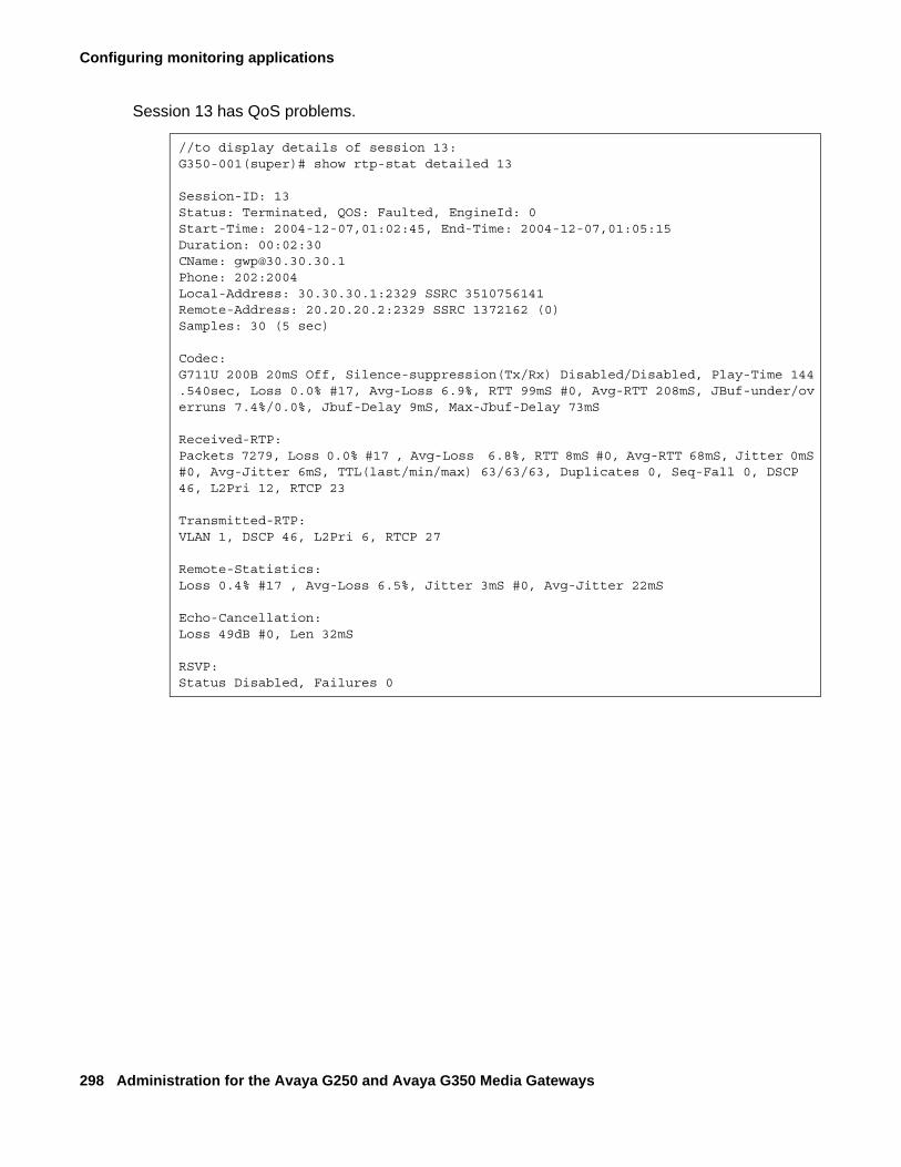
Configuring monitoring applications
298 Administration for the Avaya G250 and Avaya G350 Media Gateways
Session 13 has QoS problems.
//to display details of session 13:G350-001(super)# show rtp-stat detailed 13
Session-ID: 13Status: Terminated, QOS: Faulted, EngineId: 0Start-Time: 2004-12-07,01:02:45, End-Time: 2004-12-07,01:05:15Duration: 00:02:30CName: [email protected]: 202:2004Local-Address: 30.30.30.1:2329 SSRC 3510756141Remote-Address: 20.20.20.2:2329 SSRC 1372162 (0)Samples: 30 (5 sec)
Codec:G711U 200B 20mS Off, Silence-suppression(Tx/Rx) Disabled/Disabled, Play-Time 144.540sec, Loss 0.0% #17, Avg-Loss 6.9%, RTT 99mS #0, Avg-RTT 208mS, JBuf-under/overruns 7.4%/0.0%, Jbuf-Delay 9mS, Max-Jbuf-Delay 73mS
Received-RTP:Packets 7279, Loss 0.0% #17 , Avg-Loss 6.8%, RTT 8mS #0, Avg-RTT 68mS, Jitter 0mS #0, Avg-Jitter 6mS, TTL(last/min/max) 63/63/63, Duplicates 0, Seq-Fall 0, DSCP 46, L2Pri 12, RTCP 23
Transmitted-RTP:VLAN 1, DSCP 46, L2Pri 6, RTCP 27
Remote-Statistics:Loss 0.4% #17 , Avg-Loss 6.5%, Jitter 3mS #0, Avg-Jitter 22mS
Echo-Cancellation:Loss 49dB #0, Len 32mS
RSVP:Status Disabled, Failures 0
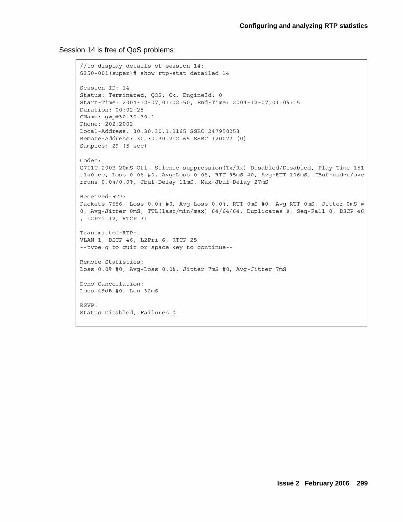
Configuring and analyzing RTP statistics
Issue 2 February 2006 299
Session 14 is free of QoS problems:
//to display details of session 14:G350-001(super)# show rtp-stat detailed 14
Session-ID: 14Status: Terminated, QOS: Ok, EngineId: 0Start-Time: 2004-12-07,01:02:50, End-Time: 2004-12-07,01:05:15Duration: 00:02:25CName: [email protected]: 202:2002Local-Address: 30.30.30.1:2165 SSRC 247950253Remote-Address: 30.30.30.2:2165 SSRC 120077 (0)Samples: 29 (5 sec)
Codec:G711U 200B 20mS Off, Silence-suppression(Tx/Rx) Disabled/Disabled, Play-Time 151.140sec, Loss 0.0% #0, Avg-Loss 0.0%, RTT 95mS #0, Avg-RTT 106mS, JBuf-under/overruns 0.0%/0.0%, Jbuf-Delay 11mS, Max-Jbuf-Delay 27mS
Received-RTP:Packets 7556, Loss 0.0% #0, Avg-Loss 0.0%, RTT 0mS #0, Avg-RTT 0mS, Jitter 0mS #0, Avg-Jitter 0mS, TTL(last/min/max) 64/64/64, Duplicates 0, Seq-Fall 0, DSCP 46, L2Pri 12, RTCP 31
Transmitted-RTP:VLAN 1, DSCP 46, L2Pri 6, RTCP 25--type q to quit or space key to continue--
Remote-Statistics:Loss 0.0% #0, Avg-Loss 0.0%, Jitter 7mS #0, Avg-Jitter 7mS
Echo-Cancellation:Loss 49dB #0, Len 32mS
RSVP:Status Disabled, Failures 0
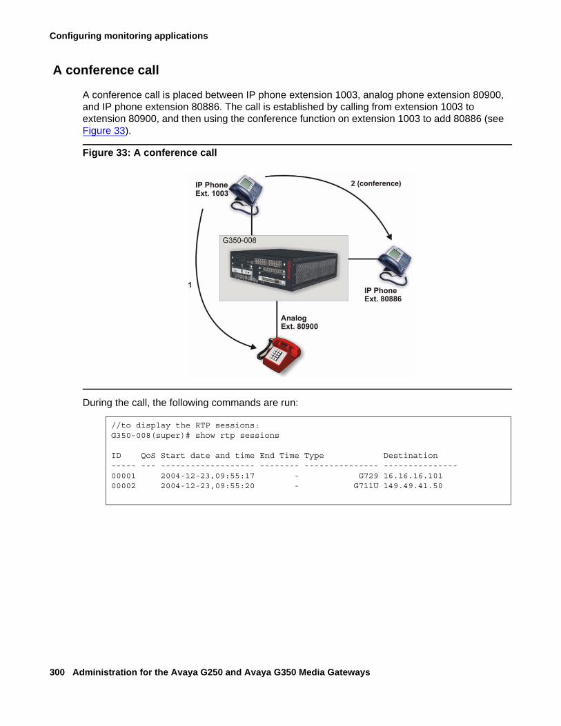
Configuring monitoring applications
300 Administration for the Avaya G250 and Avaya G350 Media Gateways
A conference call
A conference call is placed between IP phone extension 1003, analog phone extension 80900, and IP phone extension 80886. The call is established by calling from extension 1003 to extension 80900, and then using the conference function on extension 1003 to add 80886 (see Figure 33).
Figure 33: A conference call
During the call, the following commands are run:
//to display the RTP sessions:G350-008(super)# show rtp sessions
ID QoS Start date and time End Time Type Destination----- --- ------------------- -------- --------------- ---------------00001 2004-12-23,09:55:17 - G729 16.16.16.10100002 2004-12-23,09:55:20 - G711U 149.49.41.50
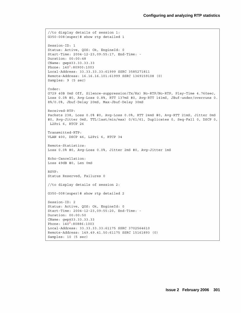
Configuring and analyzing RTP statistics
Issue 2 February 2006 301
//to display details of session 1:G350-008(super)# show rtp detailed 1
Session-ID: 1Status: Active, QOS: Ok, EngineId: 0Start-Time: 2004-12-23,09:55:17, End-Time: -Duration: 00:00:48CName: [email protected]: 1401:80900:1003Local-Address: 33.33.33.33:61999 SSRC 3585271811Remote-Address: 16.16.16.101:61999 SSRC 1369159108 (0)Samples: 9 (5 sec)
Codec:G729 40B 0mS Off, Silence-suppression(Tx/Rx) No-RTP/No-RTP, Play-Time 4.760sec,Loss 0.0% #0, Avg-Loss 0.8%, RTT 137mS #0, Avg-RTT 141mS, JBuf-under/overruns 0.8%/0.0%, Jbuf-Delay 20mS, Max-Jbuf-Delay 30mS
Received-RTP:Packets 238, Loss 0.0% #0, Avg-Loss 0.0%, RTT 24mS #0, Avg-RTT 21mS, Jitter 0mS#0, Avg-Jitter 0mS, TTL(last/min/max) 0/61/61, Duplicates 0, Seq-Fall 0, DSCP 0, L2Pri 6, RTCP 26
Transmitted-RTP:VLAN 400, DSCP 46, L2Pri 6, RTCP 34
Remote-Statistics:Loss 0.0% #0, Avg-Loss 0.0%, Jitter 2mS #0, Avg-Jitter 1mS
Echo-Cancellation:Loss 49dB #0, Len 0mS
RSVP:Status Reserved, Failures 0
//to display details of session 2:
G350-008(super)# show rtp detailed 2
Session-ID: 2Status: Active, QOS: Ok, EngineId: 0Start-Time: 2004-12-23,09:55:20, End-Time: -Duration: 00:00:50CName: [email protected]: 1402:80886:1003Local-Address: 33.33.33.33:61175 SSRC 3702564610Remote-Address: 149.49.41.50:61175 SSRC 15161893 (0)Samples: 10 (5 sec)
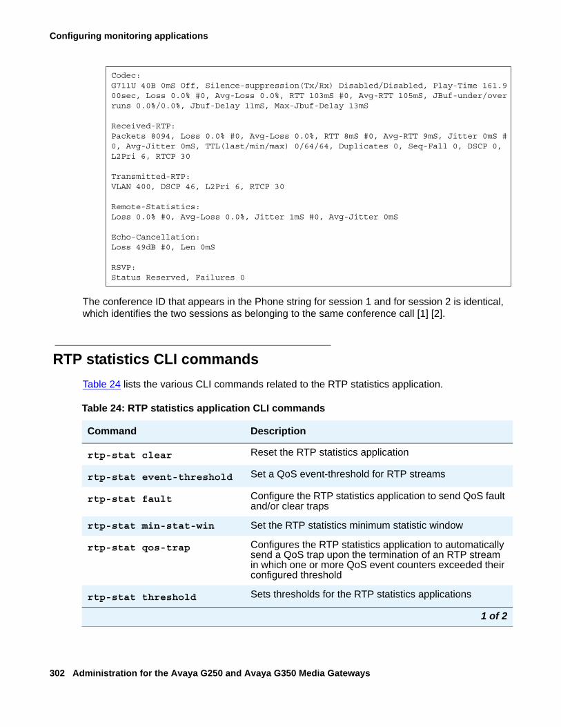
Configuring monitoring applications
302 Administration for the Avaya G250 and Avaya G350 Media Gateways
The conference ID that appears in the Phone string for session 1 and for session 2 is identical, which identifies the two sessions as belonging to the same conference call [1] [2].
RTP statistics CLI commandsTable 24 lists the various CLI commands related to the RTP statistics application.
Codec:G711U 40B 0mS Off, Silence-suppression(Tx/Rx) Disabled/Disabled, Play-Time 161.900sec, Loss 0.0% #0, Avg-Loss 0.0%, RTT 103mS #0, Avg-RTT 105mS, JBuf-under/overruns 0.0%/0.0%, Jbuf-Delay 11mS, Max-Jbuf-Delay 13mS
Received-RTP:Packets 8094, Loss 0.0% #0, Avg-Loss 0.0%, RTT 8mS #0, Avg-RTT 9mS, Jitter 0mS #0, Avg-Jitter 0mS, TTL(last/min/max) 0/64/64, Duplicates 0, Seq-Fall 0, DSCP 0,L2Pri 6, RTCP 30
Transmitted-RTP:VLAN 400, DSCP 46, L2Pri 6, RTCP 30
Remote-Statistics:Loss 0.0% #0, Avg-Loss 0.0%, Jitter 1mS #0, Avg-Jitter 0mS
Echo-Cancellation:Loss 49dB #0, Len 0mS
RSVP:Status Reserved, Failures 0
Table 24: RTP statistics application CLI commands
Command Description
rtp-stat clear Reset the RTP statistics application
rtp-stat event-threshold Set a QoS event-threshold for RTP streams
rtp-stat fault Configure the RTP statistics application to send QoS fault and/or clear traps
rtp-stat min-stat-win Set the RTP statistics minimum statistic window
rtp-stat qos-trap Configures the RTP statistics application to automatically send a QoS trap upon the termination of an RTP stream in which one or more QoS event counters exceeded their configured threshold
rtp-stat threshold Sets thresholds for the RTP statistics applications
1 of 2
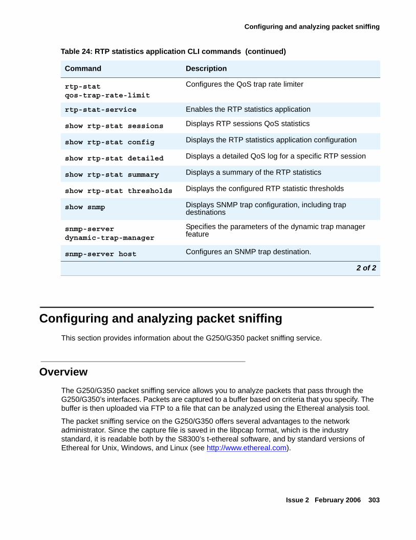
Configuring and analyzing packet sniffing
Issue 2 February 2006 303
Configuring and analyzing packet sniffingThis section provides information about the G250/G350 packet sniffing service.
OverviewThe G250/G350 packet sniffing service allows you to analyze packets that pass through the G250/G350’s interfaces. Packets are captured to a buffer based on criteria that you specify. The buffer is then uploaded via FTP to a file that can be analyzed using the Ethereal analysis tool.
The packet sniffing service on the G250/G350 offers several advantages to the network administrator. Since the capture file is saved in the libpcap format, which is the industry standard, it is readable both by the S8300’s t-ethereal software, and by standard versions of Ethereal for Unix, Windows, and Linux (see http://www.ethereal.com).
rtp-stat qos-trap-rate-limit
Configures the QoS trap rate limiter
rtp-stat-service Enables the RTP statistics application
show rtp-stat sessions Displays RTP sessions QoS statistics
show rtp-stat config Displays the RTP statistics application configuration
show rtp-stat detailed Displays a detailed QoS log for a specific RTP session
show rtp-stat summary Displays a summary of the RTP statistics
show rtp-stat thresholds Displays the configured RTP statistic thresholds
show snmp Displays SNMP trap configuration, including trap destinations
snmp-server dynamic-trap-manager
Specifies the parameters of the dynamic trap manager feature
snmp-server host Configures an SNMP trap destination.
Table 24: RTP statistics application CLI commands (continued)
Command Description
2 of 2
Configuring monitoring applications
304 Administration for the Avaya G250 and Avaya G350 Media Gateways
Note:Note: Ethereal is an open source application.
In addition, the G250/G350’s packet sniffing service is capable of capturing non-Ethernet packets, such as frame-relay and PPP. Non-Ethernet packets are wrapped in a dummy Ethernet header to allow them to be viewed in a libpcap format. Thus, the G250/G350 allows you to analyze packets on all the interfaces of the device.
The G250/G350’s packet sniffing service gives you full control over the memory usage of the sniffer. You can set a maximum limit for the capture buffer size, configure a circular buffer so that older information is overwritten when the buffer fills up, and specify a maximum number of bytes to capture for each packet.
What can be capturedThe G250/G350 packet sniffing service captures only the packets handled by the G250/G350 and delivered to the device CPU (“non-promiscuous” mode). This is unlike regular sniffer applications that pick up all traffic on the network.
Streams that can always be captured include:
● H.248 registration
● RTP from the G250/G350
● ARP on the LAN (broadcast)
● All packets that traverse the WAN
● All traffic to/from the G250/G350
Streams that can never be captured because they are switched by the internal Ethernet switch and not by the CPU include:
● H.323 Signaling from an IP phone on the LAN to an ICC on the LAN
● RTP stream between IP phones on the LAN
Streams that can be captured if the G250/G350 is the WAN router include:
● H.323 Signaling from IP phones on the LAN to an ECC over the WAN
● DHCP when the DHCP server is behind the WAN (using the G250/G350 DHCP relay capability)
● RTP stream on an IP phone on the LAN to a remote IP phone
The following sections describe how to configure packet sniffing and analyze the resulting capture file.
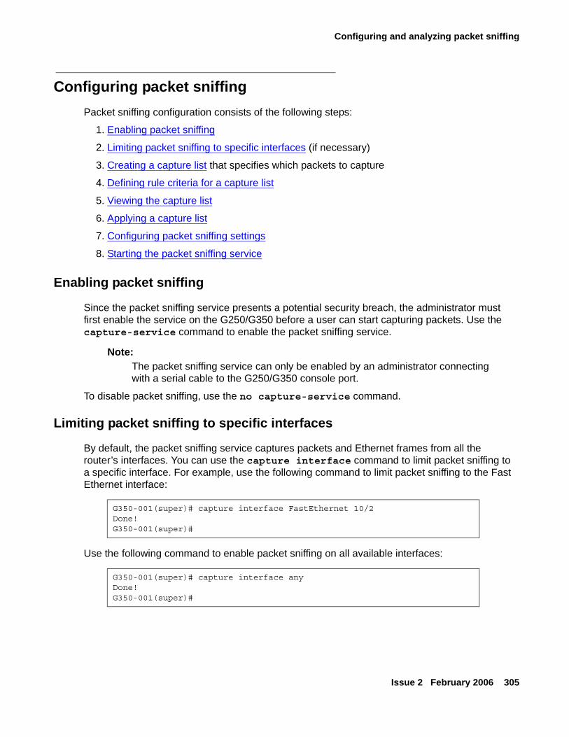
Configuring and analyzing packet sniffing
Issue 2 February 2006 305
Configuring packet sniffingPacket sniffing configuration consists of the following steps:
1. Enabling packet sniffing
2. Limiting packet sniffing to specific interfaces (if necessary)
3. Creating a capture list that specifies which packets to capture
4. Defining rule criteria for a capture list
5. Viewing the capture list
6. Applying a capture list
7. Configuring packet sniffing settings
8. Starting the packet sniffing service
Enabling packet sniffing
Since the packet sniffing service presents a potential security breach, the administrator must first enable the service on the G250/G350 before a user can start capturing packets. Use the capture-service command to enable the packet sniffing service.
Note:Note: The packet sniffing service can only be enabled by an administrator connecting
with a serial cable to the G250/G350 console port.
To disable packet sniffing, use the no capture-service command.
Limiting packet sniffing to specific interfaces
By default, the packet sniffing service captures packets and Ethernet frames from all the router’s interfaces. You can use the capture interface command to limit packet sniffing to a specific interface. For example, use the following command to limit packet sniffing to the Fast Ethernet interface:
Use the following command to enable packet sniffing on all available interfaces:
G350-001(super)# capture interface FastEthernet 10/2Done!G350-001(super)#
G350-001(super)# capture interface anyDone!G350-001(super)#
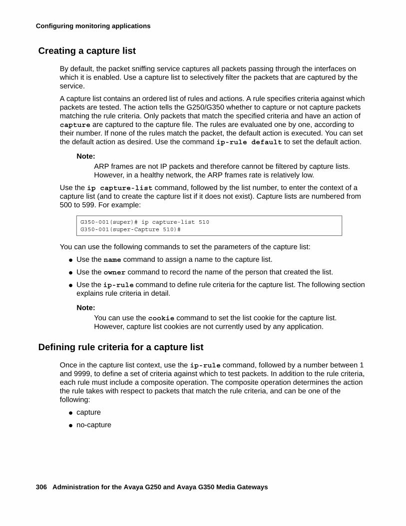
Configuring monitoring applications
306 Administration for the Avaya G250 and Avaya G350 Media Gateways
Creating a capture list
By default, the packet sniffing service captures all packets passing through the interfaces on which it is enabled. Use a capture list to selectively filter the packets that are captured by the service.
A capture list contains an ordered list of rules and actions. A rule specifies criteria against which packets are tested. The action tells the G250/G350 whether to capture or not capture packets matching the rule criteria. Only packets that match the specified criteria and have an action of capture are captured to the capture file. The rules are evaluated one by one, according to their number. If none of the rules match the packet, the default action is executed. You can set the default action as desired. Use the command ip-rule default to set the default action.
Note:Note: ARP frames are not IP packets and therefore cannot be filtered by capture lists.
However, in a healthy network, the ARP frames rate is relatively low.
Use the ip capture-list command, followed by the list number, to enter the context of a capture list (and to create the capture list if it does not exist). Capture lists are numbered from 500 to 599. For example:
You can use the following commands to set the parameters of the capture list:
● Use the name command to assign a name to the capture list.
● Use the owner command to record the name of the person that created the list.
● Use the ip-rule command to define rule criteria for the capture list. The following section explains rule criteria in detail.
Note:Note: You can use the cookie command to set the list cookie for the capture list.
However, capture list cookies are not currently used by any application.
Defining rule criteria for a capture list
Once in the capture list context, use the ip-rule command, followed by a number between 1 and 9999, to define a set of criteria against which to test packets. In addition to the rule criteria, each rule must include a composite operation. The composite operation determines the action the rule takes with respect to packets that match the rule criteria, and can be one of the following:
● capture
● no-capture
G350-001(super)# ip capture-list 510G350-001(super-Capture 510)#
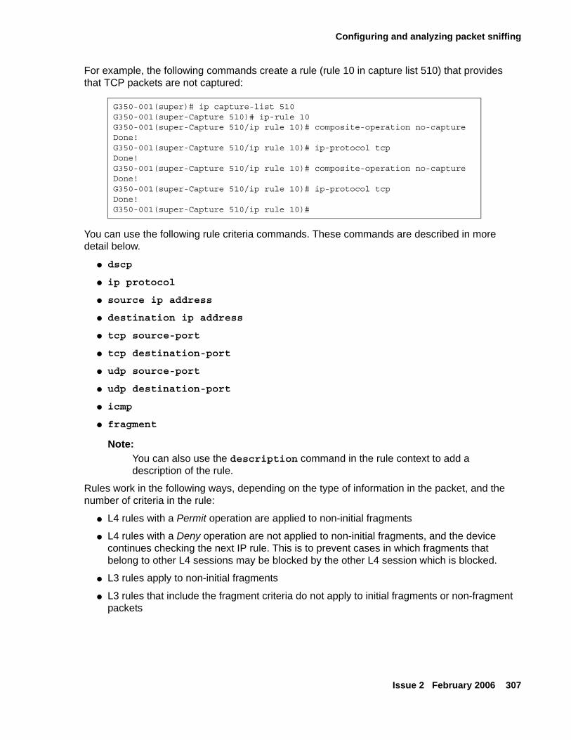
Configuring and analyzing packet sniffing
Issue 2 February 2006 307
For example, the following commands create a rule (rule 10 in capture list 510) that provides that TCP packets are not captured:
You can use the following rule criteria commands. These commands are described in more detail below.
● dscp
● ip protocol
● source ip address
● destination ip address
● tcp source-port
● tcp destination-port
● udp source-port
● udp destination-port
● icmp
● fragment
Note:Note: You can also use the description command in the rule context to add a
description of the rule.
Rules work in the following ways, depending on the type of information in the packet, and the number of criteria in the rule:
● L4 rules with a Permit operation are applied to non-initial fragments
● L4 rules with a Deny operation are not applied to non-initial fragments, and the device continues checking the next IP rule. This is to prevent cases in which fragments that belong to other L4 sessions may be blocked by the other L4 session which is blocked.
● L3 rules apply to non-initial fragments
● L3 rules that include the fragment criteria do not apply to initial fragments or non-fragment packets
G350-001(super)# ip capture-list 510G350-001(super-Capture 510)# ip-rule 10G350-001(super-Capture 510/ip rule 10)# composite-operation no-captureDone!G350-001(super-Capture 510/ip rule 10)# ip-protocol tcpDone!G350-001(super-Capture 510/ip rule 10)# composite-operation no-captureDone!G350-001(super-Capture 510/ip rule 10)# ip-protocol tcpDone!G350-001(super-Capture 510/ip rule 10)#
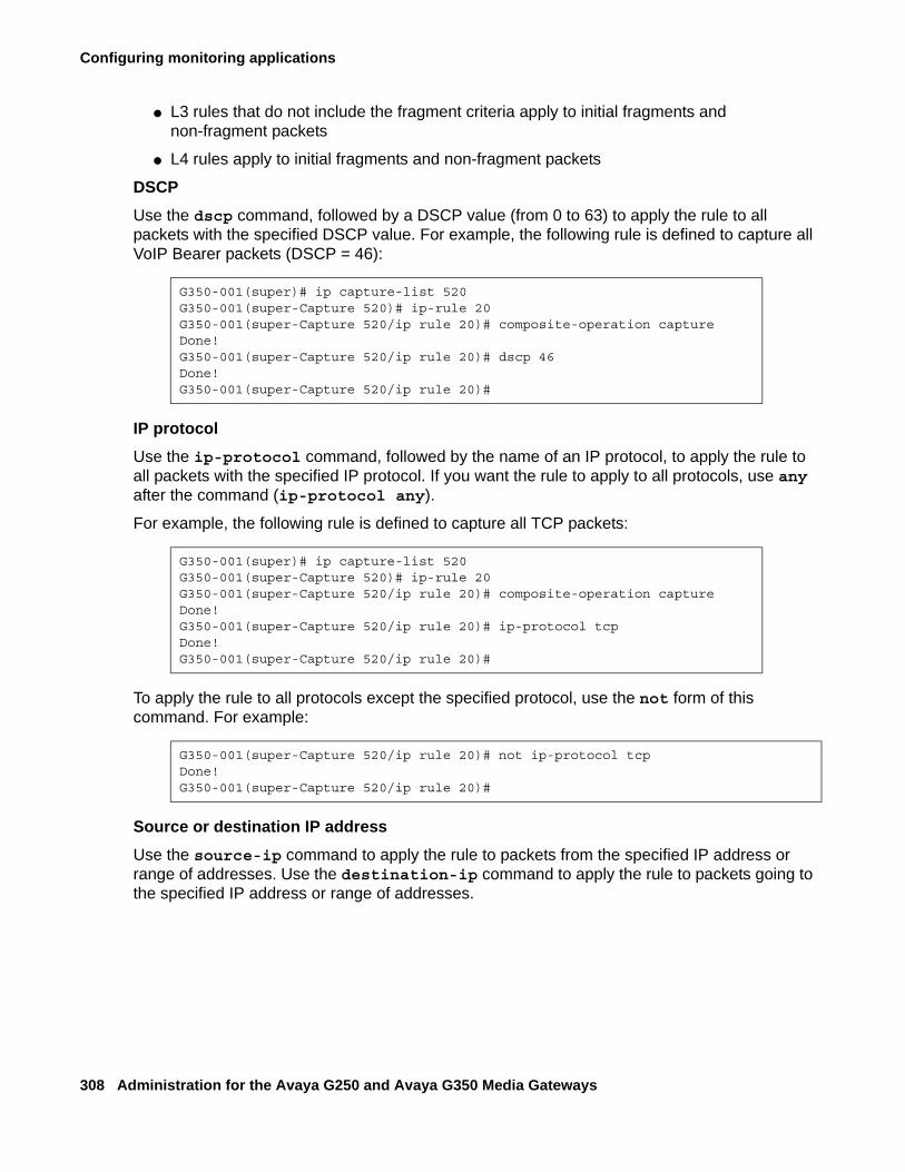
Configuring monitoring applications
308 Administration for the Avaya G250 and Avaya G350 Media Gateways
● L3 rules that do not include the fragment criteria apply to initial fragments and non-fragment packets
● L4 rules apply to initial fragments and non-fragment packets
DSCPUse the dscp command, followed by a DSCP value (from 0 to 63) to apply the rule to all packets with the specified DSCP value. For example, the following rule is defined to capture all VoIP Bearer packets (DSCP = 46):
IP protocolUse the ip-protocol command, followed by the name of an IP protocol, to apply the rule to all packets with the specified IP protocol. If you want the rule to apply to all protocols, use any after the command (ip-protocol any).
For example, the following rule is defined to capture all TCP packets:
To apply the rule to all protocols except the specified protocol, use the not form of this command. For example:
Source or destination IP addressUse the source-ip command to apply the rule to packets from the specified IP address or range of addresses. Use the destination-ip command to apply the rule to packets going to the specified IP address or range of addresses.
G350-001(super)# ip capture-list 520G350-001(super-Capture 520)# ip-rule 20G350-001(super-Capture 520/ip rule 20)# composite-operation captureDone!G350-001(super-Capture 520/ip rule 20)# dscp 46Done!G350-001(super-Capture 520/ip rule 20)#
G350-001(super)# ip capture-list 520G350-001(super-Capture 520)# ip-rule 20G350-001(super-Capture 520/ip rule 20)# composite-operation captureDone!G350-001(super-Capture 520/ip rule 20)# ip-protocol tcpDone!G350-001(super-Capture 520/ip rule 20)#
G350-001(super-Capture 520/ip rule 20)# not ip-protocol tcpDone!G350-001(super-Capture 520/ip rule 20)#
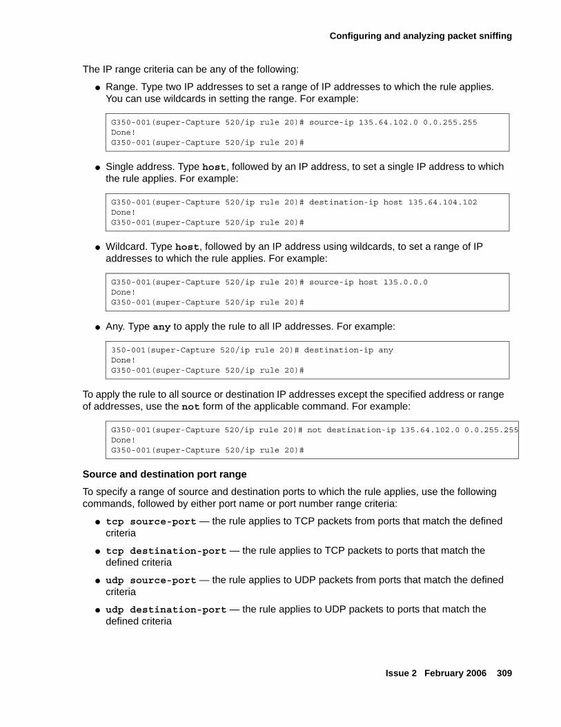
Configuring and analyzing packet sniffing
Issue 2 February 2006 309
The IP range criteria can be any of the following:
● Range. Type two IP addresses to set a range of IP addresses to which the rule applies. You can use wildcards in setting the range. For example:
● Single address. Type host, followed by an IP address, to set a single IP address to which the rule applies. For example:
● Wildcard. Type host, followed by an IP address using wildcards, to set a range of IP addresses to which the rule applies. For example:
● Any. Type any to apply the rule to all IP addresses. For example:
To apply the rule to all source or destination IP addresses except the specified address or range of addresses, use the not form of the applicable command. For example:
Source and destination port rangeTo specify a range of source and destination ports to which the rule applies, use the following commands, followed by either port name or port number range criteria:
● tcp source-port — the rule applies to TCP packets from ports that match the defined criteria
● tcp destination-port — the rule applies to TCP packets to ports that match the defined criteria
● udp source-port — the rule applies to UDP packets from ports that match the defined criteria
● udp destination-port — the rule applies to UDP packets to ports that match the defined criteria
G350-001(super-Capture 520/ip rule 20)# source-ip 135.64.102.0 0.0.255.255Done!G350-001(super-Capture 520/ip rule 20)#
G350-001(super-Capture 520/ip rule 20)# destination-ip host 135.64.104.102Done!G350-001(super-Capture 520/ip rule 20)#
G350-001(super-Capture 520/ip rule 20)# source-ip host 135.0.0.0Done!G350-001(super-Capture 520/ip rule 20)#
350-001(super-Capture 520/ip rule 20)# destination-ip anyDone!G350-001(super-Capture 520/ip rule 20)#
G350-001(super-Capture 520/ip rule 20)# not destination-ip 135.64.102.0 0.0.255.255Done!G350-001(super-Capture 520/ip rule 20)#
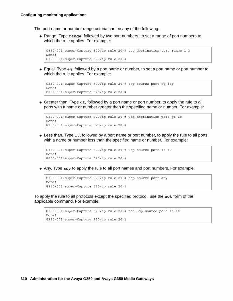
Configuring monitoring applications
310 Administration for the Avaya G250 and Avaya G350 Media Gateways
The port name or number range criteria can be any of the following:
● Range. Type range, followed by two port numbers, to set a range of port numbers to which the rule applies. For example:
● Equal. Type eq, followed by a port name or number, to set a port name or port number to which the rule applies. For example:
● Greater than. Type gt, followed by a port name or port number, to apply the rule to all ports with a name or number greater than the specified name or number. For example:
● Less than. Type lt, followed by a port name or port number, to apply the rule to all ports with a name or number less than the specified name or number. For example:
● Any. Type any to apply the rule to all port names and port numbers. For example:
To apply the rule to all protocols except the specified protocol, use the not form of the applicable command. For example:
G350-001(super-Capture 520/ip rule 20)# tcp destination-port range 1 3Done!G350-001(super-Capture 520/ip rule 20)#
G350-001(super-Capture 520/ip rule 20)# tcp source-port eq ftpDone!G350-001(super-Capture 520/ip rule 20)#
G350-001(super-Capture 520/ip rule 20)# udp destination-port gt 10Done!G350-001(super-Capture 520/ip rule 20)#
G350-001(super-Capture 520/ip rule 20)# udp source-port lt 10Done!G350-001(super-Capture 520/ip rule 20)#
G350-001(super-Capture 520/ip rule 20)# tcp source-port anyDone!G350-001(super-Capture 520/ip rule 20)#
G350-001(super-Capture 520/ip rule 20)# not udp source-port lt 10Done!G350-001(super-Capture 520/ip rule 20)#
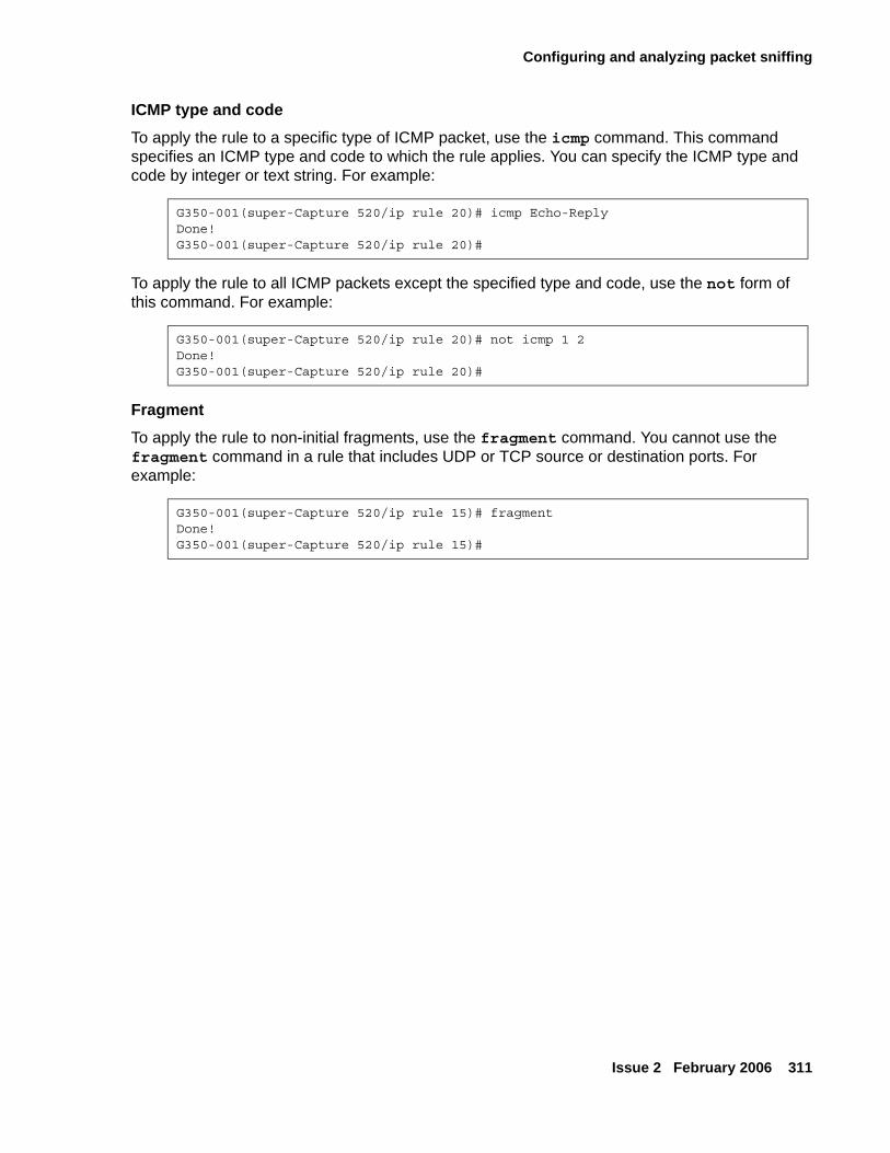
Configuring and analyzing packet sniffing
Issue 2 February 2006 311
ICMP type and codeTo apply the rule to a specific type of ICMP packet, use the icmp command. This command specifies an ICMP type and code to which the rule applies. You can specify the ICMP type and code by integer or text string. For example:
To apply the rule to all ICMP packets except the specified type and code, use the not form of this command. For example:
FragmentTo apply the rule to non-initial fragments, use the fragment command. You cannot use the fragment command in a rule that includes UDP or TCP source or destination ports. For example:
G350-001(super-Capture 520/ip rule 20)# icmp Echo-ReplyDone!G350-001(super-Capture 520/ip rule 20)#
G350-001(super-Capture 520/ip rule 20)# not icmp 1 2Done!G350-001(super-Capture 520/ip rule 20)#
G350-001(super-Capture 520/ip rule 15)# fragmentDone!G350-001(super-Capture 520/ip rule 15)#
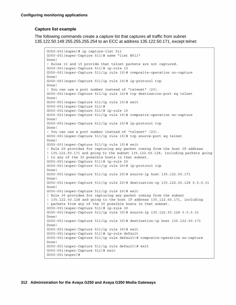
Configuring monitoring applications
312 Administration for the Avaya G250 and Avaya G350 Media Gateways
Capture list exampleThe following commands create a capture list that captures all traffic from subnet 135.122.50.149 255.255.255.254 to an ECC at address 135.122.50.171, except telnet:
G350-001(super)# ip capture-list 511G350-001(super-Capture 511)# name "list #511"Done!! Rules 10 and 15 provide that telnet packets are not captured.G350-001(super-Capture 511)# ip-rule 10G350-001(super-Capture 511/ip rule 10)# composite-operation no-captureDone!G350-001(super-Capture 511/ip rule 10)# ip-protocol tcpDone!! You can use a port number instead of "telenet" (23).G350-001(super-Capture 511/ip rule 10)# tcp destination-port eq telnetDone!G350-001(super-Capture 511/ip rule 10)# exitG350-001(super-Capture 511)#G350-001(super-Capture 511)# ip-rule 15G350-001(super-Capture 511/ip rule 15)# composite-operation no-captureDone!G350-001(super-Capture 511/ip rule 15)# ip-protocol tcpDone!! You can use a port number instead of "telenet" (23).G350-001(super-Capture 511/ip rule 15)# tcp source-port eq telnetDone!G350-001(super-Capture 511/ip rule 15)# exit! Rule 20 provides for capturing any packet coming from the host IP address! 135.122.50.171 and going to the subnet 135.122.50.128, including packets going ! to any of the 30 possible hosts in that subnet.G350-001(super-Capture 511)# ip-rule 20G350-001(super-Capture 511/ip rule 20)# ip-protocol tcpDone!G350-001(super-Capture 511/ip rule 20)# source-ip host 135.122.50.171Done!G350-001(super-Capture 511/ip rule 20)# destination-ip 135.122.50.128 0.0.0.31Done!G350-001(super-Capture 511/ip rule 20)# exit! Rule 30 provides for capturing any packet coming from the subnet! 135.122.50.128 and going to the host IP address 135.122.50.171, including! packets from any of the 30 possible hosts in that subnet.G350-001(super-Capture 511)# ip-rule 30G350-001(super-Capture 511/ip rule 30)# source-ip 135.122.50.128 0.0.0.31Done!G350-001(super-Capture 511/ip rule 30)# destination-ip host 135.122.50.171Done!G350-001(super-Capture 511/ip rule 30)# exitG350-001(super-Capture 511)# ip-rule defaultG350-001(super-Capture 511/ip rule default)# composite-operation no-captureDone!G350-001(super-Capture 511/ip rule default)# exitG350-001(super-Capture 511)# exitG350-001(super)#
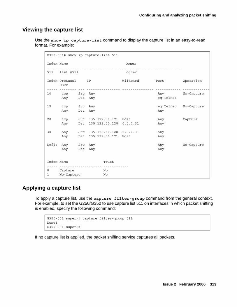
Configuring and analyzing packet sniffing
Issue 2 February 2006 313
Viewing the capture list
Use the show ip capture-list command to display the capture list in an easy-to-read format. For example:
Applying a capture list
To apply a capture list, use the capture filter-group command from the general context. For example, to set the G250/G350 to use capture list 511 on interfaces in which packet sniffing is enabled, specify the following command:
If no capture list is applied, the packet sniffing service captures all packets.
G350-001# show ip capture-list 511
Index Name Owner----- ------------------------------- --------------------------511 list #511 other
Index Protocol IP Wildcard Port Operation DSCP----- -------- --- ---------------- --------------- ------------ -------------10 tcp Src Any Any No-Capture Any Dst Any eq Telnet 15 tcp Src Any eq Telnet No-Capture Any Dst Any Any
20 tcp Src 135.122.50.171 Host Any Capture Any Dst 135.122.50.128 0.0.0.31 Any
30 Any Src 135.122.50.128 0.0.0.31 Any Any Dst 135.122.50.171 Host Any
Deflt Any Src Any Any No-Capture Any Dst Any Any
Index Name Trust----- -------------------- ------------0 Capture No1 No-Capture No
G350-001(super)# capture filter-group 511Done!G350-001(super)#
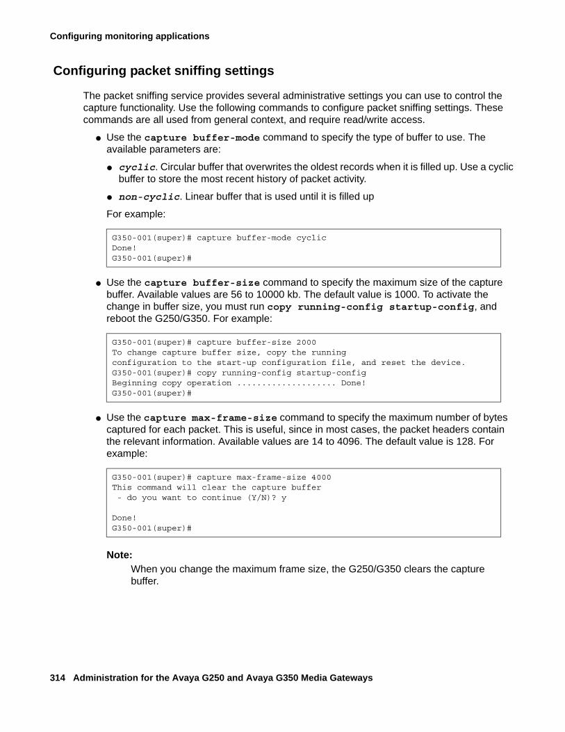
Configuring monitoring applications
314 Administration for the Avaya G250 and Avaya G350 Media Gateways
Configuring packet sniffing settings
The packet sniffing service provides several administrative settings you can use to control the capture functionality. Use the following commands to configure packet sniffing settings. These commands are all used from general context, and require read/write access.
● Use the capture buffer-mode command to specify the type of buffer to use. The available parameters are:
● cyclic. Circular buffer that overwrites the oldest records when it is filled up. Use a cyclic buffer to store the most recent history of packet activity.
● non-cyclic. Linear buffer that is used until it is filled up
For example:
● Use the capture buffer-size command to specify the maximum size of the capture buffer. Available values are 56 to 10000 kb. The default value is 1000. To activate the change in buffer size, you must run copy running-config startup-config, and reboot the G250/G350. For example:
● Use the capture max-frame-size command to specify the maximum number of bytes captured for each packet. This is useful, since in most cases, the packet headers contain the relevant information. Available values are 14 to 4096. The default value is 128. For example:
Note:Note: When you change the maximum frame size, the G250/G350 clears the capture
buffer.
G350-001(super)# capture buffer-mode cyclicDone!G350-001(super)#
G350-001(super)# capture buffer-size 2000To change capture buffer size, copy the runningconfiguration to the start-up configuration file, and reset the device.G350-001(super)# copy running-config startup-configBeginning copy operation .................... Done!G350-001(super)#
G350-001(super)# capture max-frame-size 4000This command will clear the capture buffer - do you want to continue (Y/N)? y
Done!G350-001(super)#
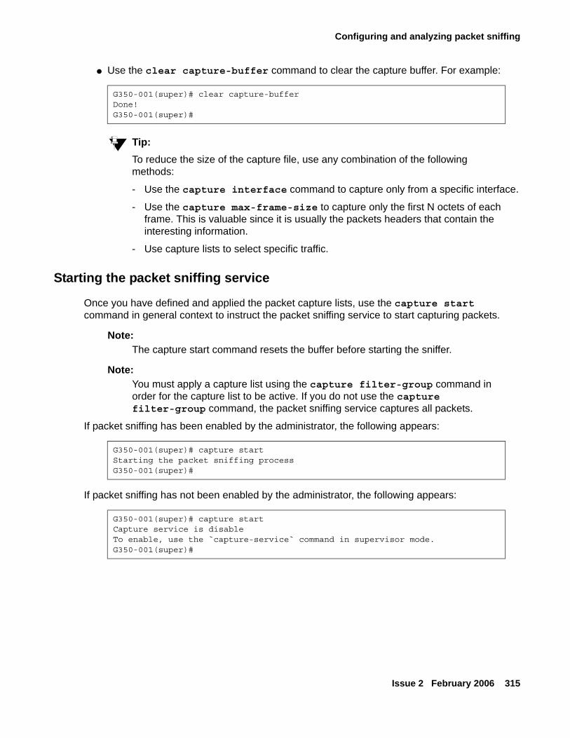
Configuring and analyzing packet sniffing
Issue 2 February 2006 315
● Use the clear capture-buffer command to clear the capture buffer. For example:
Tip:Tip: To reduce the size of the capture file, use any combination of the following
methods:
- Use the capture interface command to capture only from a specific interface.
- Use the capture max-frame-size to capture only the first N octets of each frame. This is valuable since it is usually the packets headers that contain the interesting information.
- Use capture lists to select specific traffic.
Starting the packet sniffing service
Once you have defined and applied the packet capture lists, use the capture start command in general context to instruct the packet sniffing service to start capturing packets.
Note:Note: The capture start command resets the buffer before starting the sniffer.
Note:Note: You must apply a capture list using the capture filter-group command in
order for the capture list to be active. If you do not use the capture filter-group command, the packet sniffing service captures all packets.
If packet sniffing has been enabled by the administrator, the following appears:
If packet sniffing has not been enabled by the administrator, the following appears:
G350-001(super)# clear capture-bufferDone!G350-001(super)#
G350-001(super)# capture startStarting the packet sniffing processG350-001(super)#
G350-001(super)# capture startCapture service is disableTo enable, use the `capture-service` command in supervisor mode.G350-001(super)#
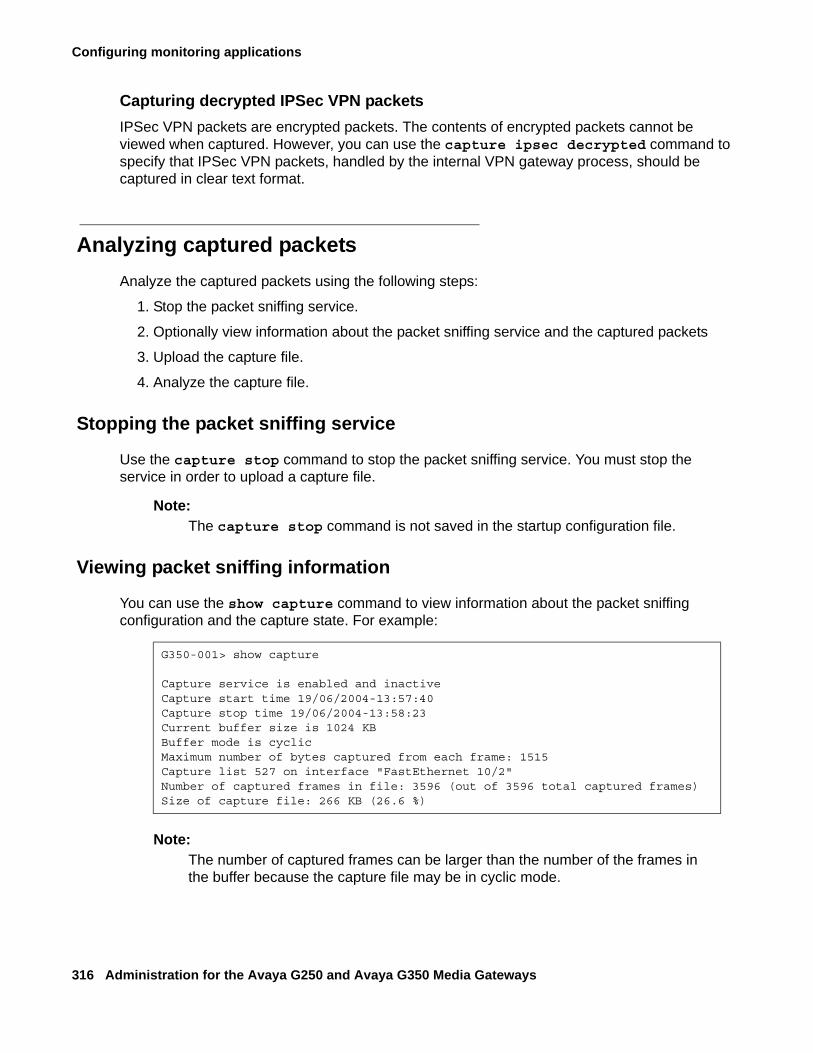
Configuring monitoring applications
316 Administration for the Avaya G250 and Avaya G350 Media Gateways
Capturing decrypted IPSec VPN packetsIPSec VPN packets are encrypted packets. The contents of encrypted packets cannot be viewed when captured. However, you can use the capture ipsec decrypted command to specify that IPSec VPN packets, handled by the internal VPN gateway process, should be captured in clear text format.
Analyzing captured packetsAnalyze the captured packets using the following steps:
1. Stop the packet sniffing service.
2. Optionally view information about the packet sniffing service and the captured packets
3. Upload the capture file.
4. Analyze the capture file.
Stopping the packet sniffing service
Use the capture stop command to stop the packet sniffing service. You must stop the service in order to upload a capture file.
Note:Note: The capture stop command is not saved in the startup configuration file.
Viewing packet sniffing information
You can use the show capture command to view information about the packet sniffing configuration and the capture state. For example:
Note:Note: The number of captured frames can be larger than the number of the frames in
the buffer because the capture file may be in cyclic mode.
G350-001> show capture
Capture service is enabled and inactiveCapture start time 19/06/2004-13:57:40Capture stop time 19/06/2004-13:58:23Current buffer size is 1024 KBBuffer mode is cyclicMaximum number of bytes captured from each frame: 1515Capture list 527 on interface "FastEthernet 10/2"Number of captured frames in file: 3596 (out of 3596 total captured frames)Size of capture file: 266 KB (26.6 %)
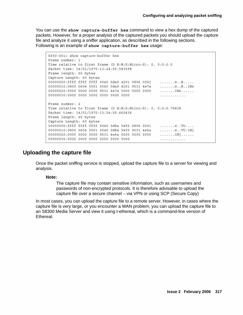
Configuring and analyzing packet sniffing
Issue 2 February 2006 317
You can use the show capture-buffer hex command to view a hex dump of the captured packets. However, for a proper analysis of the captured packets you should upload the capture file and analyze it using a sniffer application, as described in the following sections. Following is an example of show capture-buffer hex usage:
Uploading the capture file
Once the packet sniffing service is stopped, upload the capture file to a server for viewing and analysis.
Note:Note: The capture file may contain sensitive information, such as usernames and
passwords of non-encrypted protocols. It is therefore advisable to upload the capture file over a secure channel – via VPN or using SCP (Secure Copy)
In most cases, you can upload the capture file to a remote server. However, in cases where the capture file is very large, or you encounter a WAN problem, you can upload the capture file to an S8300 Media Server and view it using t-ethereal, which is a command-line version of Ethereal.
G350-001> show capture-buffer hexFrame number: 1Time relative to first frame (D H:M:S:Micro-S): 0, 0:0:0.0Packet time: 14/01/1970-13:24:55.583598Frame length: 60 bytesCapture Length: 60 bytes00000000:ffff ffff ffff 0040 0da9 4201 0806 0001 [email protected]:0800 0604 0001 0040 0da9 4201 9531 4e7a [email protected]:0000 0000 0000 9531 4e7a 0000 0000 0000 .......1Nz......00000030:0000 0000 0000 0000 0000 0000 ............
Frame number: 2Time relative to first frame (D H:M:S:Micro-S): 0, 0:0:0.76838Packet time: 14/01/1970-13:24:55.660436Frame length: 60 bytesCapture Length: 60 bytes00000000:ffff ffff ffff 0040 0d8a 5455 0806 0001 [email protected]:0800 0604 0001 0040 0d8a 5455 9531 4e6a [email protected]:0000 0000 0000 9531 4e6a 0000 0000 0000 .......1Nj......00000030:0000 0000 0000 0000 0000 0000 ............
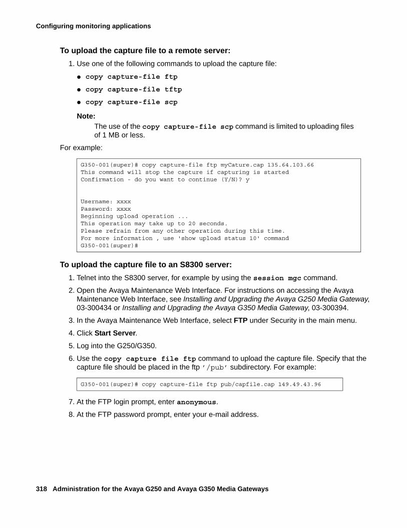
Configuring monitoring applications
318 Administration for the Avaya G250 and Avaya G350 Media Gateways
To upload the capture file to a remote server:1. Use one of the following commands to upload the capture file:
● copy capture-file ftp
● copy capture-file tftp
● copy capture-file scp
Note:Note: The use of the copy capture-file scp command is limited to uploading files
of 1 MB or less.
For example:
To upload the capture file to an S8300 server:1. Telnet into the S8300 server, for example by using the session mgc command.
2. Open the Avaya Maintenance Web Interface. For instructions on accessing the Avaya Maintenance Web Interface, see Installing and Upgrading the Avaya G250 Media Gateway, 03-300434 or Installing and Upgrading the Avaya G350 Media Gateway, 03-300394.
3. In the Avaya Maintenance Web Interface, select FTP under Security in the main menu.
4. Click Start Server.5. Log into the G250/G350.
6. Use the copy capture file ftp command to upload the capture file. Specify that the capture file should be placed in the ftp ’/pub’ subdirectory. For example:
7. At the FTP login prompt, enter anonymous.
8. At the FTP password prompt, enter your e-mail address.
G350-001(super)# copy capture-file ftp myCature.cap 135.64.103.66This command will stop the capture if capturing is startedConfirmation - do you want to continue (Y/N)? y
Username: xxxxPassword: xxxxBeginning upload operation ...This operation may take up to 20 seconds.Please refrain from any other operation during this time.For more information , use 'show upload status 10' commandG350-001(super)#
G350-001(super)# copy capture-file ftp pub/capfile.cap 149.49.43.96
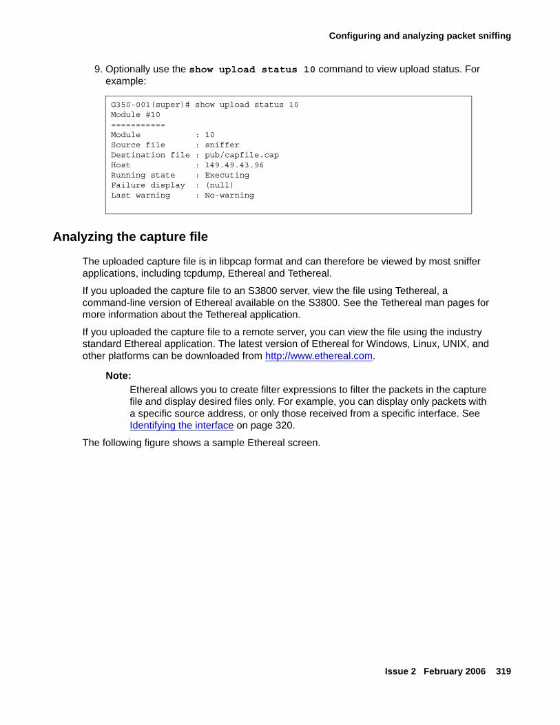
Configuring and analyzing packet sniffing
Issue 2 February 2006 319
9. Optionally use the show upload status 10 command to view upload status. For example:
Analyzing the capture file
The uploaded capture file is in libpcap format and can therefore be viewed by most sniffer applications, including tcpdump, Ethereal and Tethereal.
If you uploaded the capture file to an S3800 server, view the file using Tethereal, a command-line version of Ethereal available on the S3800. See the Tethereal man pages for more information about the Tethereal application.
If you uploaded the capture file to a remote server, you can view the file using the industry standard Ethereal application. The latest version of Ethereal for Windows, Linux, UNIX, and other platforms can be downloaded from http://www.ethereal.com.
Note:Note: Ethereal allows you to create filter expressions to filter the packets in the capture
file and display desired files only. For example, you can display only packets with a specific source address, or only those received from a specific interface. See Identifying the interface on page 320.
The following figure shows a sample Ethereal screen.
G350-001(super)# show upload status 10Module #10===========Module : 10Source file : snifferDestination file : pub/capfile.capHost : 149.49.43.96Running state : ExecutingFailure display : (null)Last warning : No-warning
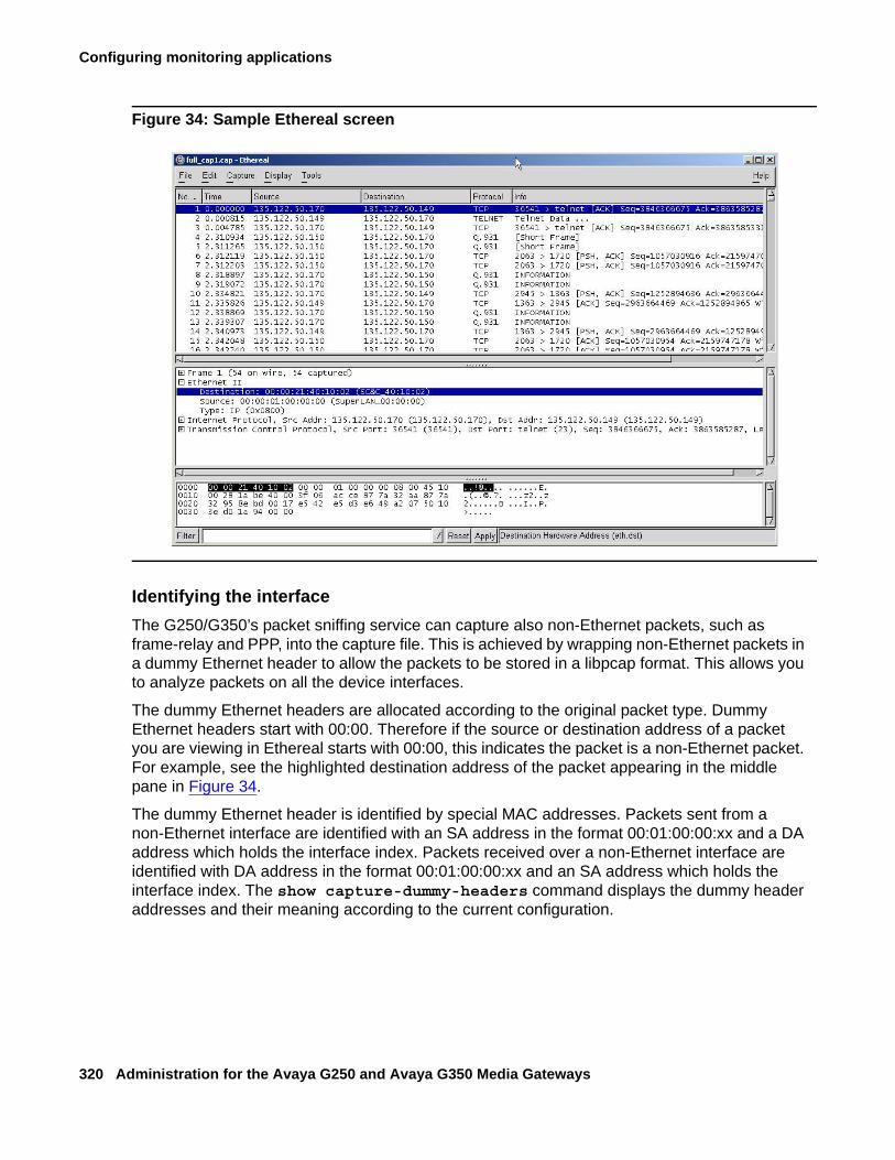
Configuring monitoring applications
320 Administration for the Avaya G250 and Avaya G350 Media Gateways
Figure 34: Sample Ethereal screen
Identifying the interfaceThe G250/G350’s packet sniffing service can capture also non-Ethernet packets, such as frame-relay and PPP, into the capture file. This is achieved by wrapping non-Ethernet packets in a dummy Ethernet header to allow the packets to be stored in a libpcap format. This allows you to analyze packets on all the device interfaces.
The dummy Ethernet headers are allocated according to the original packet type. Dummy Ethernet headers start with 00:00. Therefore if the source or destination address of a packet you are viewing in Ethereal starts with 00:00, this indicates the packet is a non-Ethernet packet. For example, see the highlighted destination address of the packet appearing in the middle pane in Figure 34.
The dummy Ethernet header is identified by special MAC addresses. Packets sent from a non-Ethernet interface are identified with an SA address in the format 00:01:00:00:xx and a DA address which holds the interface index. Packets received over a non-Ethernet interface are identified with DA address in the format 00:01:00:00:xx and an SA address which holds the interface index. The show capture-dummy-headers command displays the dummy header addresses and their meaning according to the current configuration.
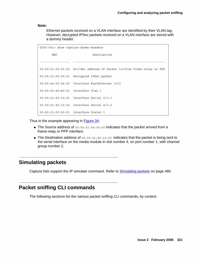
Configuring and analyzing packet sniffing
Issue 2 February 2006 321
Note:Note: Ethernet packets received on a VLAN interface are identified by their VLAN tag.
However, decrypted IPSec packets received on a VLAN interface are stored with a dummy header.
Thus in the example appearing in Figure 34:
● The Source address of 00:00:01:00:00:00 indicates that the packet arrived from a frame-relay or PPP interface.
● The Destination address of 00:00:21:40:10:02 indicates that the packet is being sent to the serial interface on the media module in slot number 4, on port number 1, with channel group number 2.
Simulating packetsCapture lists support the IP simulate command. Refer to Simulating packets on page 485.
Packet sniffing CLI commandsThe following sections list the various packet sniffing CLI commands, by context.
G350-001> show capture-dummy-headers
MAC Description
----------------- ----------------------------------------------------
00:00:01:00:00:00 Src/dst address of Packet to/from frame-relay or PPP
00:00:01:00:00:01 Decrypted IPSec packet
00:00:0a:00:0a:02 Interface FastEthernet 10/2
00:00:0c:a0:b0:01 Interface Vlan 1
00:00:21:20:10:01 Interface Serial 2/1:1
00:00:21:40:10:02 Interface Serial 4/1:2
00:00:31:00:00:01 Interface Dialer 1
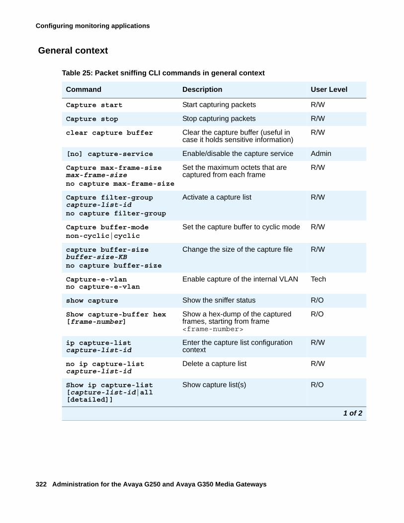
Configuring monitoring applications
322 Administration for the Avaya G250 and Avaya G350 Media Gateways
General context
Table 25: Packet sniffing CLI commands in general context
Command Description User Level
Capture start Start capturing packets R/W
Capture stop Stop capturing packets R/W
clear capture buffer Clear the capture buffer (useful in case it holds sensitive information)
R/W
[no] capture-service Enable/disable the capture service Admin
Capture max-frame-size max-frame-sizeno capture max-frame-size
Set the maximum octets that are captured from each frame
R/W
Capture filter-group capture-list-idno capture filter-group
Activate a capture list R/W
Capture buffer-mode non-cyclic|cyclic
Set the capture buffer to cyclic mode R/W
capture buffer-size buffer-size-KBno capture buffer-size
Change the size of the capture file R/W
Capture-e-vlanno capture-e-vlan
Enable capture of the internal VLAN Tech
show capture Show the sniffer status R/O
Show capture-buffer hex [frame-number]
Show a hex-dump of the captured frames, starting from frame <frame-number>
R/O
ip capture-list capture-list-id
Enter the capture list configuration context
R/W
no ip capture-list capture-list-id
Delete a capture list R/W
Show ip capture-list [capture-list-id|all [detailed]]
Show capture list(s) R/O
1 of 2
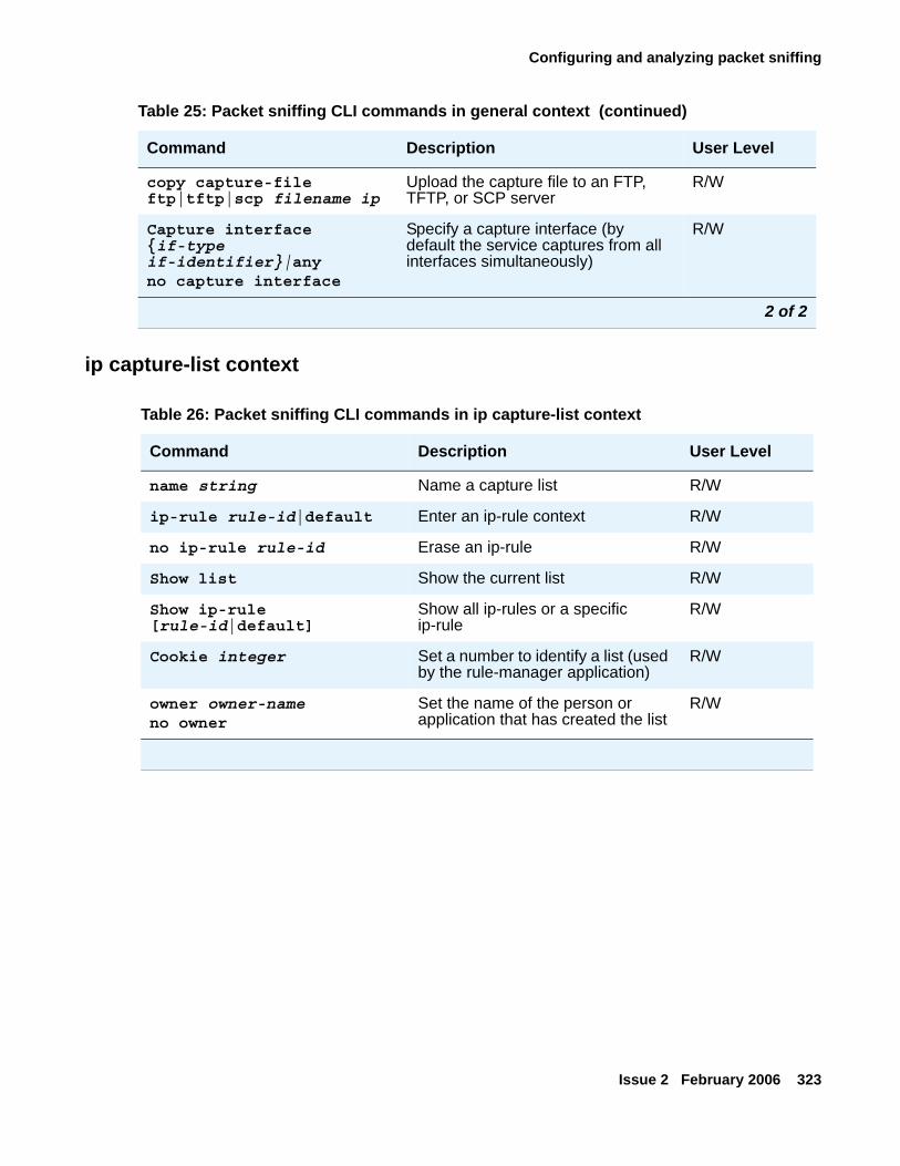
Configuring and analyzing packet sniffing
Issue 2 February 2006 323
ip capture-list context
copy capture-file ftp|tftp|scp filename ip
Upload the capture file to an FTP, TFTP, or SCP server
R/W
Capture interface {if-type if-identifier}|anyno capture interface
Specify a capture interface (by default the service captures from all interfaces simultaneously)
R/W
Table 25: Packet sniffing CLI commands in general context (continued)
Command Description User Level
2 of 2
Table 26: Packet sniffing CLI commands in ip capture-list context
Command Description User Level
name string Name a capture list R/W
ip-rule rule-id|default Enter an ip-rule context R/W
no ip-rule rule-id Erase an ip-rule R/W
Show list Show the current list R/W
Show ip-rule [rule-id|default]
Show all ip-rules or a specific ip-rule
R/W
Cookie integer Set a number to identify a list (used by the rule-manager application)
R/W
owner owner-nameno owner
Set the name of the person or application that has created the list
R/W
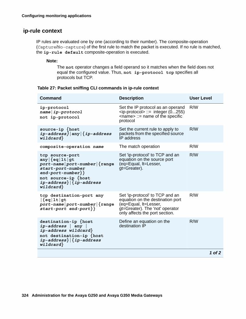
Configuring monitoring applications
324 Administration for the Avaya G250 and Avaya G350 Media Gateways
ip-rule context
IP rules are evaluated one by one (according to their number). The composite-operation (Capture/No-capture) of the first rule to match the packet is executed. If no rule is matched, the ip-rule default composite-operation is executed.
Note:Note: The not operator changes a field operand so it matches when the field does not
equal the configured value. Thus, not ip-protocol tcp specifies all protocols but TCP.
Table 27: Packet sniffing CLI commands in ip-rule context
Command Description User Level
ip-protocol name|ip-protocolnot ip-protocol
Set the IP protocol as an operand<ip-protocol> ::= integer (0...255)<name> ::= name of the specific protocol
R/W
source-ip {host ip-address}|any|{ip-address wildcard}
Set the current rule to apply to packets from the specified source IP address
R/W
composite-operation name The match operation R/W
tcp source-port any|{eq|lt|gt port-name|port-number|{range start-port-number end-port-number}}not source-ip {host ip-address}|{ip-address wildcard}
Set 'ip-protocol' to TCP and an equation on the source port (eq=Equal, lt=Lesser, gt=Greater).
R/W
tcp destination-port any |{eq|lt|gt port-name|port-number|{range start-port end-port}}
Set 'ip-protocol' to TCP and an equation on the destination port (eq=Equal, lt=Lesser, gt=Greater). The 'not' operator only affects the port section.
R/W
destination-ip {host ip-address | any | ip-address wildcard}not destination-ip {host ip-address}|{ip-address wildcard}
Define an equation on the destination IP
R/W
1 of 2
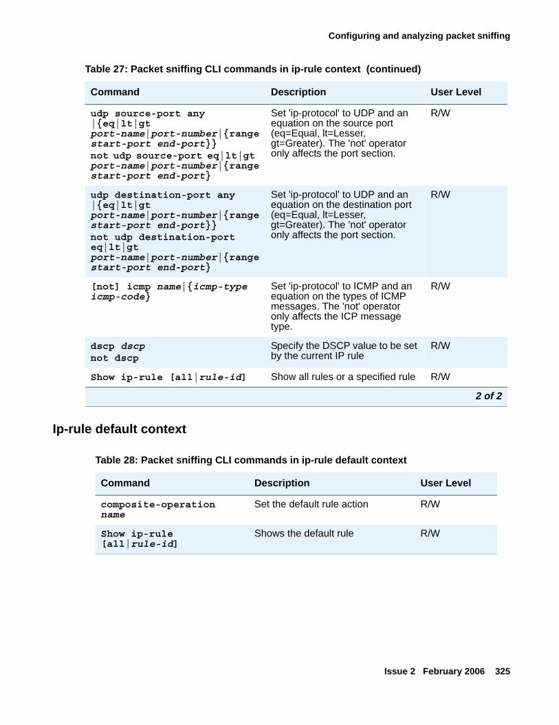
Configuring and analyzing packet sniffing
Issue 2 February 2006 325
Ip-rule default context
udp source-port any |{eq|lt|gt port-name|port-number|{range start-port end-port}}not udp source-port eq|lt|gt port-name|port-number|{range start-port end-port}
Set 'ip-protocol' to UDP and an equation on the source port (eq=Equal, lt=Lesser, gt=Greater). The 'not' operator only affects the port section.
R/W
udp destination-port any |{eq|lt|gt port-name|port-number|{range start-port end-port}}not udp destination-port eq|lt|gt port-name|port-number|{range start-port end-port}
Set 'ip-protocol' to UDP and an equation on the destination port (eq=Equal, lt=Lesser, gt=Greater). The 'not' operator only affects the port section.
R/W
[not] icmp name|{icmp-type icmp-code}
Set 'ip-protocol' to ICMP and an equation on the types of ICMP messages. The 'not' operator only affects the ICP message type.
R/W
dscp dscpnot dscp
Specify the DSCP value to be set by the current IP rule
R/W
Show ip-rule [all|rule-id] Show all rules or a specified rule R/W
Table 27: Packet sniffing CLI commands in ip-rule context (continued)
Command Description User Level
2 of 2
Table 28: Packet sniffing CLI commands in ip-rule default context
Command Description User Level
composite-operation name
Set the default rule action R/W
Show ip-rule [all|rule-id]
Shows the default rule R/W
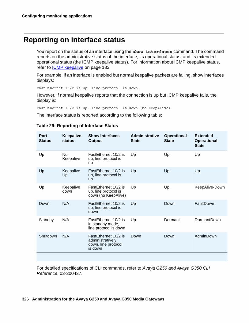
Configuring monitoring applications
326 Administration for the Avaya G250 and Avaya G350 Media Gateways
Reporting on interface statusYou report on the status of an interface using the show interfaces command. The command reports on the administrative status of the interface, its operational status, and its extended operational status (the ICMP keepalive status). For information about ICMP keepalive status, refer to ICMP keepalive on page 183.
For example, if an interface is enabled but normal keepalive packets are failing, show interfaces displays:FastEthernet 10/2 is up, line protocol is down
However, if normal keepalive reports that the connection is up but ICMP keepalive fails, the display is:FastEthernet 10/2 is up, line protocol is down (no KeepAlive)
The interface status is reported according to the following table:
For detailed specifications of CLI commands, refer to Avaya G250 and Avaya G350 CLI Reference, 03-300437.
Table 29: Reporting of Interface Status
PortStatus
Keepalive status
Show Interfaces Output
AdministrativeState
Operational State
Extended Operational State
Up No Keepalive
FastEthernet 10/2 is up, line protocol is up
Up Up Up
Up Keepalive Up
FastEthernet 10/2 is up, line protocol is up
Up Up Up
Up Keepalive down
FastEthernet 10/2 is up, line protocol is down (no KeepAlive)
Up Up KeepAlive-Down
Down N/A FastEthernet 10/2 is up, line protocol is down
Up Down FaultDown
Standby N/A FastEthernet 10/2 is in standby mode, line protocol is down
Up Dormant DormantDown
Shutdown N/A FastEthernet 10/2 is administratively down, line protocol is down
Down Down AdminDown
Configuring and monitoring CNA test plugs
Issue 2 February 2006 327
Configuring and monitoring CNA test plugsThis section describes how to configure and monitor the activity of the CNA test plug service available in G250/G350 Media Gateways and includes the following topics:
● CNA test plug overview
● CNA test plug functionality
● Configuring the G250/G350 test plug for registration
● CNA test plug configuration example
CNA test plug overviewThe Converged Network Analyzer (CNA) is a distributed system for real-time monitoring of IP networks, using active measurements. The CNA supports various network tests including connectivity tests with pings, topology tests with traceroute, and QoS tests with synthetic RTP streams. Within a CNA system, test plugs are the entities that execute the tests, according to instructions from CNA schedulers, and return the results. For more information about administrating the CNA system, see IM R3.0 Converged Network Analyzer (CNA) Configuration, 14-300284.
CNA test plug functionalityWhen activated, test plugs present themselves to the CNA system in a process called registration. During registration, a test plug publishes its IP address and active ports, and authenticates and exchanges encryption keys with CNA Schedulers.The schedulers are software components running on single board computers called chatterboxes. Schedulers are responsible for initiating tests, coordinating tests, and collecting the test results.For redundancy and load sharing, CNA systems usually include multiple chatterboxes and, therefore, multiple schedulers. However, the schedulers distribute test plug registration parameters among themselves, and so, a test plug only has to register with a single scheduler. test plug administrators typically configure multiple schedulers addresses, for redundancy.You can configure a list of up to five scheduler IP addresses. The test plug attempts to register with the first scheduler on the list first, and then moves down the list as necessary if the registration isn’t successful.When the test plug registers with a scheduler, the test plug provides the scheduler with its IP address, and two UDP port numbers, called the control port and the RTP echo port. The test plug IP address is the IP address of the interface on which the PMI is configured.
Configuring monitoring applications
328 Administration for the Avaya G250 and Avaya G350 Media Gateways
Once registered, the test plug listens for test requests on the control port. When the test plug receives an authenticated and validly formatted test request from the scheduler, the test plug:
● Injects any one of the tests specified in the test request into the network
● Performs the specified test using the parameter values passed in the test request
● Upon successful completion of the test, sends the test results to the analyzer of the Chatterbox whose IP Address is designated in the test request
The G250/G350 test plug supports all CNA tests, which are:
● Traceroute. Measures per-hop round-trip delays to a target IP address by sending a sequence of hop-limited UDP messages, each with a TTL (time-to-live) value that is one greater than that of the preceding message.
● Real Time Protocol (RTP). Measures delay, packet loss, and jitter to another test plug by sending a simulated RTP stream that is echoed back.
● Ping. Sends an ICMP echo message to a target IP address, and reports whether or not a response was returned.
● Transmission Control Protocol (TCP) Connect. Attempts to establish a TCP connection to a specified port at a target IP address and reports whether the attempt succeeded or failed and the time taken by the TCP packet to reach its destination.
● Merge. Chatter test that is used, transparently to the user, to identify a single device with multiple IP addresses and to merge its multiple appearances into one in the network topology map.
When the test plug receives a request to run an RTP test, the test plug uses a UDP port called the RTP test port to send an RTP stream to another test plug. The test plug listens on the RTP echo port for RTP streams sent by other test plugs running RTP tests. All the UDP ports have default values, which can be overridden using CLI commands. The defaults are:
● Control port: 8889
● RTP echo port: 8888
● RTP test port: 8887
Any changes you make to the test plug configuration, such as changing scheduler addresses or port numbers, only take effect when you cause the test plug to disconnect from the scheduler and register again.
Configuring the G250/G350 test plug for registrationFrom the G250/G350 CLI, you can configure the G250/G350 test plug to register with a CNA scheduler.
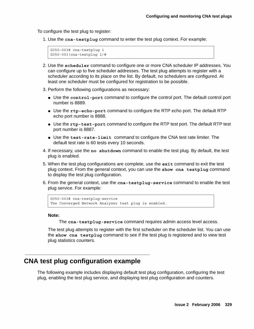
Configuring and monitoring CNA test plugs
Issue 2 February 2006 329
To configure the test plug to register:
1. Use the cna-testplug command to enter the test plug context. For example:
2. Use the scheduler command to configure one or more CNA scheduler IP addresses. You can configure up to five scheduler addresses. The test plug attempts to register with a scheduler according to its place on the list. By default, no schedulers are configured. At least one scheduler must be configured for registration to be possible.
3. Perform the following configurations as necessary:
● Use the control-port command to configure the control port. The default control port number is 8889.
● Use the rtp-echo-port command to configure the RTP echo port. The default RTP echo port number is 8888.
● Use the rtp-test-port command to configure the RTP test port. The default RTP test port number is 8887.
● Use the test-rate-limit command to configure the CNA test rate limiter. The default test rate is 60 tests every 10 seconds.
4. If necessary, use the no shutdown command to enable the test plug. By default, the test plug is enabled.
5. When the test plug configurations are complete, use the exit command to exit the test plug context. From the general context, you can use the show cna testplug command to display the test plug configuration.
6. From the general context, use the cna-testplug-service command to enable the test plug service. For example:
Note:Note: The cna-testplug-service command requires admin access level access.
The test plug attempts to register with the first scheduler on the scheduler list. You can use the show cna testplug command to see if the test plug is registered and to view test plug statistics counters.
CNA test plug configuration exampleThe following example includes displaying default test plug configuration, configuring the test plug, enabling the test plug service, and displaying test plug configuration and counters.
G350-003# cna-testplug 1G350-003(cna-testplug 1)#
G350-003# cna-testplug-serviceThe Converged Network Analyzer test plug is enabled.
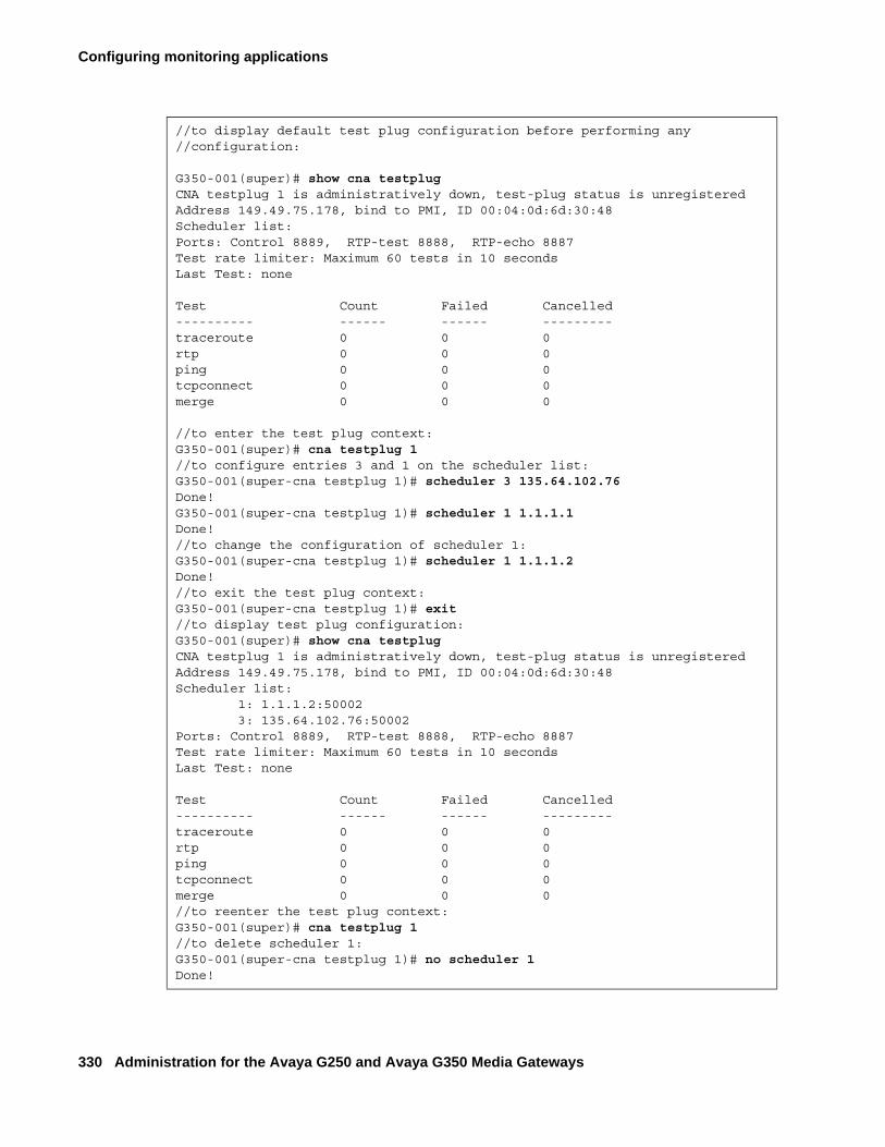
Configuring monitoring applications
330 Administration for the Avaya G250 and Avaya G350 Media Gateways
//to display default test plug configuration before performing any //configuration:
G350-001(super)# show cna testplugCNA testplug 1 is administratively down, test-plug status is unregisteredAddress 149.49.75.178, bind to PMI, ID 00:04:0d:6d:30:48Scheduler list:Ports: Control 8889, RTP-test 8888, RTP-echo 8887Test rate limiter: Maximum 60 tests in 10 secondsLast Test: none
Test Count Failed Cancelled---------- ------ ------ ---------traceroute 0 0 0rtp 0 0 0ping 0 0 0tcpconnect 0 0 0merge 0 0 0
//to enter the test plug context:G350-001(super)# cna testplug 1//to configure entries 3 and 1 on the scheduler list:G350-001(super-cna testplug 1)# scheduler 3 135.64.102.76Done!G350-001(super-cna testplug 1)# scheduler 1 1.1.1.1Done!//to change the configuration of scheduler 1: G350-001(super-cna testplug 1)# scheduler 1 1.1.1.2Done!//to exit the test plug context:G350-001(super-cna testplug 1)# exit//to display test plug configuration:G350-001(super)# show cna testplugCNA testplug 1 is administratively down, test-plug status is unregisteredAddress 149.49.75.178, bind to PMI, ID 00:04:0d:6d:30:48Scheduler list: 1: 1.1.1.2:50002 3: 135.64.102.76:50002Ports: Control 8889, RTP-test 8888, RTP-echo 8887Test rate limiter: Maximum 60 tests in 10 secondsLast Test: none
Test Count Failed Cancelled---------- ------ ------ ---------traceroute 0 0 0rtp 0 0 0ping 0 0 0tcpconnect 0 0 0merge 0 0 0//to reenter the test plug context:G350-001(super)# cna testplug 1//to delete scheduler 1:G350-001(super-cna testplug 1)# no scheduler 1Done!
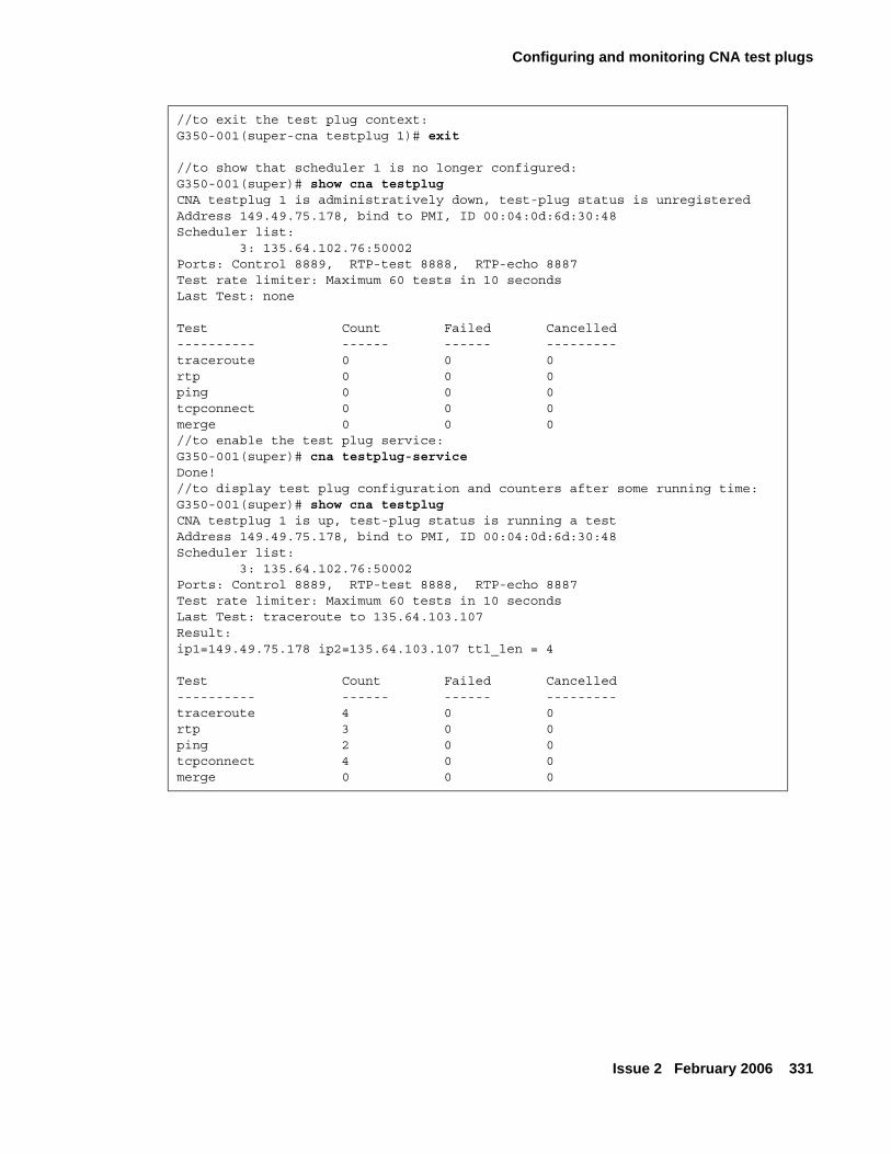
Configuring and monitoring CNA test plugs
Issue 2 February 2006 331
//to exit the test plug context:G350-001(super-cna testplug 1)# exit
//to show that scheduler 1 is no longer configured:G350-001(super)# show cna testplugCNA testplug 1 is administratively down, test-plug status is unregisteredAddress 149.49.75.178, bind to PMI, ID 00:04:0d:6d:30:48Scheduler list: 3: 135.64.102.76:50002Ports: Control 8889, RTP-test 8888, RTP-echo 8887Test rate limiter: Maximum 60 tests in 10 secondsLast Test: none
Test Count Failed Cancelled---------- ------ ------ ---------traceroute 0 0 0rtp 0 0 0ping 0 0 0tcpconnect 0 0 0merge 0 0 0//to enable the test plug service:G350-001(super)# cna testplug-serviceDone!//to display test plug configuration and counters after some running time:G350-001(super)# show cna testplugCNA testplug 1 is up, test-plug status is running a testAddress 149.49.75.178, bind to PMI, ID 00:04:0d:6d:30:48Scheduler list: 3: 135.64.102.76:50002Ports: Control 8889, RTP-test 8888, RTP-echo 8887Test rate limiter: Maximum 60 tests in 10 secondsLast Test: traceroute to 135.64.103.107Result:ip1=149.49.75.178 ip2=135.64.103.107 ttl_len = 4
Test Count Failed Cancelled---------- ------ ------ ---------traceroute 4 0 0rtp 3 0 0ping 2 0 0tcpconnect 4 0 0merge 0 0 0

Configuring monitoring applications
332 Administration for the Avaya G250 and Avaya G350 Media Gateways
Issue 2 February 2006 333
Chapter 18: Configuring the router
This chapter provides information about configuring the G250/G350 router and contains the following sections:
● Overview of the G250 and G350 router — a list of features supported on the G250/G350 router, along with instructions for enabling and disabling the router
● Configuring interfaces — instructions on how to configure Fast Ethernet, Loopback, Serial, and VLAN interfaces on the router
● Configuring unnumbered IP interfaces — instructions on how to configure a point-to-point interface to borrow an IP address from another interface, rather than assigning the interface its own IP address
● Configuring the routing table — instructions on how to configure the routing table
● Configuring GRE tunneling — instructions on how to configure GRE tunnels on the router
● Configuring DHCP and BOOTP relay — instructions on how to configure DHCP and BOOTP relays for routing on the G250/G350
● Configuring DHCP server — instructions on how to configure DHCP server on the G250/G350
● Configuring broadcast relay — instructions on how to configure broadcast relay for routing on the G250/G350
● Configuring the ARP table — instructions on how to configure the ARP table
● Enabling proxy ARP — instructions on how to enable proxy ARP on an interface
● Configuring ICMP errors — instructions on how to configure whether the router sends ICMP error messages
● Configuring RIP — instructions on how to configure RIP parameters for each interface on the router
● Configuring OSPF — instructions on how to configure OSPF parameters for each interface on the router
● Route redistribution — instructions on how to configure route redistribution among multiple routing protocols
● Configuring VRRP — instructions on how to configure the VRRP protocol so as to support redundancy of LAN routers and load balancing
● Configuring fragmentation — instructions on how to configure IP fragmentation and reassembly on the G250/G350 router
Configuring the router
334 Administration for the Avaya G250 and Avaya G350 Media Gateways
Overview of the G250 and G350 routerThe Avaya G250 and G350 Media Gateways each have an internal router. You can configure the following routing features on the router:
● Interfaces
● Unnumbered IP interfaces
● Routing table
● GRE tunneling
● DHCP and BOOTP relay
● DHCP server
● Broadcast relay
● ARP table
● ICMP errors
● RIP
● OSPF
● Route redistribution
● VRRP
● Fragmentation
Use the ip routing command to enable the router. Use the no form of this command to disable the router.
Configuring interfacesThis section provides information about configuring interfaces on the router and includes the following topics:
● Router interface concepts — a description of the types of interfaces that you can configure on the G250/G350 router
● IP Interface configuration commands — a list and descriptions of the CLI commands used to configure interfaces on the G250/G350 router
● Interface configuration examples — examples of router interface configurations
Configuring interfaces
Issue 2 February 2006 335
Router interface conceptsThe router in the Avaya G250/G350 Media Gateway includes the following interface categories:
● physical
● Layer 2 virtual
● Layer 3 routing
Physical router interfacesThe following are the physical interfaces of the G250/G350 router:
● WAN Interfaces — When you add a WAN media module to the Avaya G250/G350 Media Gateway, the media module provides a WAN interface. You can add one of the following types of WAN media modules:
- The Avaya MM340 media module provides an E1/T1 WAN interface.
- The Avaya MM342 media module provides a USP WAN interface.
● Fast Ethernet Interface — The 10/2 Fast Ethernet port on the front panel of the G250 and G350 provides a Fast Ethernet interface. This interface is an autosensing 10/100Mbps Fast Ethernet port. It can be used to connect to a LAN, an external firewall, an external Virtual Private Network (VPN), or a DeMilitarized Zone (DMZ). This interface can also be used as a WAN interface when configured for PPPoE. For more information, see Configuring PPPoE on page 155.
● Switching Interface — An internal 100Mbps connection to the G250 and G350 internal switch provides a switching interface. The switching interface supports VLANs. By default, the switching interface is associated with the first VLAN (Vlan 1).
When you configure the G250 or G350 without an external VPN or firewall, Vlan 1 is used to connect the internal G250/G350 router to the internal G250/G350 switch. If an external firewall or VPN is connected to the Fast Ethernet port, it is important to disable Vlan 1 to prevent a direct flow of packets from the WAN to the LAN.
Layer 2 virtual interfaces● Loopback — The Loopback interface is a virtual Layer 2 interface over which Loopback IP
addresses are configured. The Loopback interface represents the router by an IP address that is always available, a feature necessary mainly for network troubleshooting.
Since the Loopback interface is not connected to any physical interface, an entry in the routing table can not have the Loopback interface’s subnet as its next hop.
● GRE tunnel — A GRE tunnel is a virtual point-to-point link using two routers at two ends of an Internet cloud as its endpoints. GRE tunneling encapsulates packets and sends them over a GRE tunnel. At the end of the GRE tunnel, the encapsulation is removed and the packet is sent to its destination in the network at the far end of the GRE tunnel. For more information, see Configuring GRE tunneling on page 343.
Configuring the router
336 Administration for the Avaya G250 and Avaya G350 Media Gateways
Layer 2 logical interfaces
● VLAN (on the Switching Interface) — The G250/G350 switch can have multiple VLANs defined within its switching fabric. Both the G250 and the G350 router support up to eight VLANs that can be configured over their internal switching interface connections.
● Serial Interface — A serial interface is a virtual interface that is created over a portion of an E1/T1 or USP port. Serial interfaces support PPP and frame relay encapsulation protocols. For more information about configuring serial interfaces for a WAN, see Initial WAN configuration on page 149.
● Dialer Interface — is used for the modem dial-backup feature. Refer to Modem dial backup on page 164.
Note:Note: One or more IP interfaces can be defined over each serial, Fast Ethernet,
switching, and Loopback interface.
IP Interface configuration commandsTo configure an interface:
1. To create an interface, type the interface command, followed by the type of interface you want to create. Some types of interfaces require an identifier as a parameter. Other types of interfaces require the interface’s module and port number as a parameter. For example:
interface vlan 1interface serial 2/1
2. Use the ip address command, followed by an IP address and subnet mask, to assign an IP address to the interface. Use the no form of this command to delete the IP interface.
Use the following commands to configure the interface parameters. For more information about these commands, see Avaya G250 and Avaya G350 CLI Reference, 03-300437.
● Use the ip admin-state command to set the administrative state of the IP interface. The default state is up.
● Use the ip broadcast-address command to update the interface broadcast address.
Configuring unnumbered IP interfaces
Issue 2 February 2006 337
Interface configuration examplesUse the following commands to configure the fixed router port with IP address 10.20.30.40 and subnet mask 255.255.0.0:
Use the following commands to create VLAN 2 on the Switching Interface and configure it with IP address 10.30.50.70 and subnet mask 255.255.0.0:
Configuring unnumbered IP interfacesThis section describes how to configured an unnumbered IP interface, and includes the following sections:
● Unnumbered IP overview
● Configuring unnumbered IP on an interface
● Unnumbered IP examples
Unnumbered IP overviewUnnumbered IP is a feature that enables you to configure a point-to-point interface to borrow an IP address from another interface. Unnumbered IP enables IP processing on a point-to-point interface without assigning an explicit IP address to the interface. Although unnumbered IP is supported on all point-to-point interfaces, the main use of the feature is to enable dynamic routing on the Dialer interface. The Dialer interface is used for the modem dial-backup feature. Refer to Modem dial backup on page 164. Modem dial-backup is a feature that sets up a backup dialing destination for a branch gateway. Modem dial-backup requires unnumbered IP to be configured on the Dialer interface of the branch gateway and at both the default and the backup dialing destinations.
G350-001# interface FastEthernet 10/2G350-001(if:FastEthernet 10/2)# ip address 10.20.30.40 255.255.0.0Done!
G350-001# interface Vlan 2G350-001(if:Vlan 2)# ip address 10.30.50.70 255.255.0.0Done!
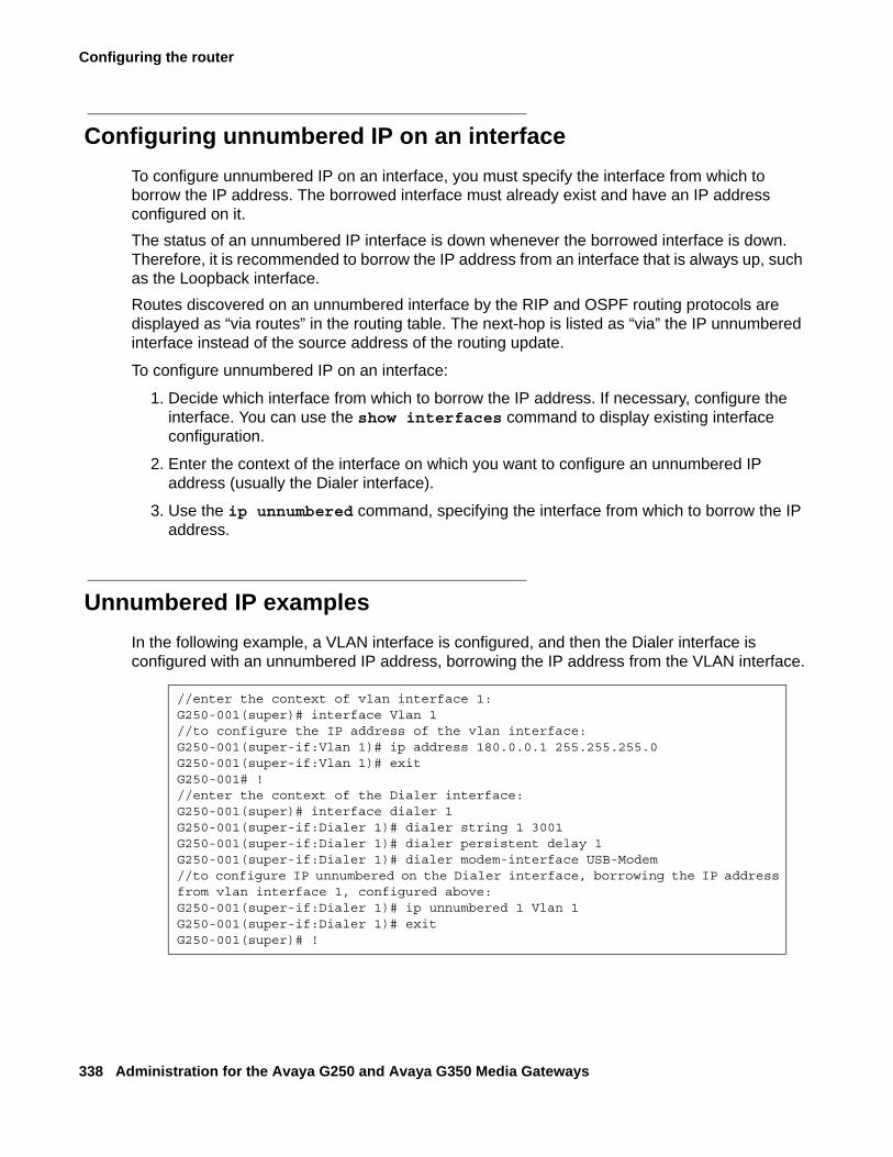
Configuring the router
338 Administration for the Avaya G250 and Avaya G350 Media Gateways
Configuring unnumbered IP on an interfaceTo configure unnumbered IP on an interface, you must specify the interface from which to borrow the IP address. The borrowed interface must already exist and have an IP address configured on it. The status of an unnumbered IP interface is down whenever the borrowed interface is down. Therefore, it is recommended to borrow the IP address from an interface that is always up, such as the Loopback interface.Routes discovered on an unnumbered interface by the RIP and OSPF routing protocols are displayed as “via routes” in the routing table. The next-hop is listed as “via” the IP unnumbered interface instead of the source address of the routing update.
To configure unnumbered IP on an interface:
1. Decide which interface from which to borrow the IP address. If necessary, configure the interface. You can use the show interfaces command to display existing interface configuration.
2. Enter the context of the interface on which you want to configure an unnumbered IP address (usually the Dialer interface).
3. Use the ip unnumbered command, specifying the interface from which to borrow the IP address.
Unnumbered IP examplesIn the following example, a VLAN interface is configured, and then the Dialer interface is configured with an unnumbered IP address, borrowing the IP address from the VLAN interface.
//enter the context of vlan interface 1:G250-001(super)# interface Vlan 1//to configure the IP address of the vlan interface:G250-001(super-if:Vlan 1)# ip address 180.0.0.1 255.255.255.0G250-001(super-if:Vlan 1)# exitG250-001# !//enter the context of the Dialer interface:G250-001(super)# interface dialer 1G250-001(super-if:Dialer 1)# dialer string 1 3001G250-001(super-if:Dialer 1)# dialer persistent delay 1G250-001(super-if:Dialer 1)# dialer modem-interface USB-Modem//to configure IP unnumbered on the Dialer interface, borrowing the IP address from vlan interface 1, configured above:G250-001(super-if:Dialer 1)# ip unnumbered 1 Vlan 1G250-001(super-if:Dialer 1)# exitG250-001(super)# !
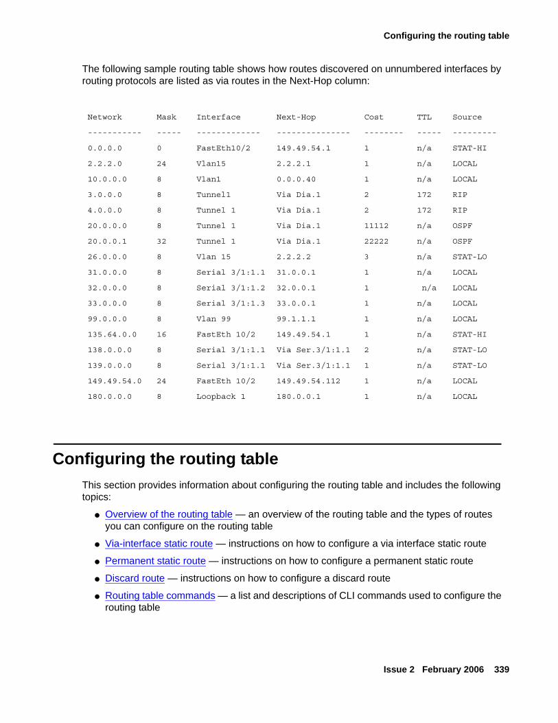
Configuring the routing table
Issue 2 February 2006 339
The following sample routing table shows how routes discovered on unnumbered interfaces by routing protocols are listed as via routes in the Next-Hop column:
Configuring the routing tableThis section provides information about configuring the routing table and includes the following topics:
● Overview of the routing table — an overview of the routing table and the types of routes you can configure on the routing table
● Via-interface static route — instructions on how to configure a via interface static route
● Permanent static route — instructions on how to configure a permanent static route
● Discard route — instructions on how to configure a discard route
● Routing table commands — a list and descriptions of CLI commands used to configure the routing table
Network Mask Interface Next-Hop Cost TTL Source
----------- ----- ------------- --------------- -------- ----- ---------
0.0.0.0 0 FastEth10/2 149.49.54.1 1 n/a STAT-HI
2.2.2.0 24 Vlan15 2.2.2.1 1 n/a LOCAL
10.0.0.0 8 Vlan1 0.0.0.40 1 n/a LOCAL
3.0.0.0 8 Tunnel1 Via Dia.1 2 172 RIP
4.0.0.0 8 Tunnel 1 Via Dia.1 2 172 RIP
20.0.0.0 8 Tunnel 1 Via Dia.1 11112 n/a OSPF
20.0.0.1 32 Tunnel 1 Via Dia.1 22222 n/a OSPF
26.0.0.0 8 Vlan 15 2.2.2.2 3 n/a STAT-LO
31.0.0.0 8 Serial 3/1:1.1 31.0.0.1 1 n/a LOCAL
32.0.0.0 8 Serial 3/1:1.2 32.0.0.1 1 n/a LOCAL
33.0.0.0 8 Serial 3/1:1.3 33.0.0.1 1 n/a LOCAL
99.0.0.0 8 Vlan 99 99.1.1.1 1 n/a LOCAL
135.64.0.0 16 FastEth 10/2 149.49.54.1 1 n/a STAT-HI
138.0.0.0 8 Serial 3/1:1.1 Via Ser.3/1:1.1 2 n/a STAT-LO
139.0.0.0 8 Serial 3/1:1.1 Via Ser.3/1:1.1 1 n/a STAT-LO
149.49.54.0 24 FastEth 10/2 149.49.54.112 1 n/a LOCAL
180.0.0.0 8 Loopback 1 180.0.0.1 1 n/a LOCAL
Configuring the router
340 Administration for the Avaya G250 and Avaya G350 Media Gateways
Overview of the routing tableWhen you configure the routing table, you can:
● View information about the routing table
● Add entries to the routing table
● Delete entries from the routing table
Note:Note: To change an entry in the routing table, delete the entry and then add it as a new
entry.
The routes in the routing table are static routes. They are never timed-out, and can only be removed manually. If you delete the interface, all static routes on the interface are also deleted.
A static route becomes inactive whenever the underlying Layer 2 interface is down, except for permanent static routes. You can disable the interface manually using the IP admin-state down command. For more information, see Permanent static route on page 342. When the underlying Layer 2 interface becomes active, the static route enters the routing table again.
You can monitor the status of non-permanent static routes by applying object tracking to the route. Thus, if the track state is changed to down then the static route state is changed to inactive, and if the track state is changed to up then the static route state is changed to active. For more information on object tracking, see Object tracking on page 187.
Static routes can be configured with the following as next-hops:
● Via-interface route — specifies a serial interface as the next-hop, without a specific next-hop IP address. See Via-interface static route on page 341.
● Next-hop IP address — specifies the IP address of a router as a next-hop. The next-hop router must belong to one of the directly attached networks for which the Avaya G250/G350 Media Gateway has an IP interface.
Two kinds of static routes can be configured:
● High Preference static routes — preferred to routes learned from any routing protocol
● Low Preference static routes — used temporarily until the route is learned from a routing protocol.
By default, a static route has low preference.
Static routes can be advertised by routing protocols, such as RIP and OSPF. For more information, see Route redistribution on page 373. Static routes also support load-balancing similar to OSPF. You can configure up to three next-hops for each static route in one of the following manners:
● Enter all of the next-hops using a single ip route command. To add a new next-hop to an existing static route, enter the new next-hop individually, as in the following option.
● Enter each next-hop individually with it’s own ip route command.
Configuring the routing table
Issue 2 February 2006 341
Note:Note: If you apply tracking to a static route, you can only configure one next-hop for the
route.
Using the no ip route command deletes the route including all of its next-hops, whether entered individually or with a single command. For example, to specify next-hops 149.49.54.1 and 149.49.75.1 as a static route to the network 10.1.1.0, perform one of the following:
● Use the single ip route 10.1.1.0 24 149.49.54.1 149.49.75.1 command specifying all next-hops together,
Or
● Use the individual ip route 10.1.1.0 24 149.49.54.1 and ip route 10.1.1.0 24 149.49.75.1 commands.
Next-hops can only be added to an existing static route if they have the same preference and metric as the currently defined next-hops.
Note:Note: Metrics are used to choose between routes of the same protocol. Preferences
are used to choose between routes of different protocols.
The Avaya G250/G350 Media Gateway supports the following Static Route configurations:
● Via-interface static route
● Permanent static route
● Discard route
Via-interface static routePPP and frame relay allow for a Layer 3 interface to be established without knowing in advance the next-hop on the other side of a serial link. In this case you can specify a Serial Layer 2 interface or a GRE tunnel as a next-hop instead of providing a specific next-hop IP address. This is equivalent to specifying the node on the other side of the serial link as the next-hop when its IP address is unknown. The via interface option is configured by specifying the type and the number of the serial interface using the ip route command.
Note:Note: The interface used in the via route must have an IP address attached to it.
For example, the command ip route 193.168.10.0 24 serial 2/1:1 creates a static route to the network 193.168.10.0 24 via the Serial 2/1:1 interface.
A static route can have both via interface and IP addressed next-hops, with a maximum of three next-hops. If such a combination is required, separate ip route commands should be used for the via interface static route and the IP addressed next-hop routes. Also, if more than one via interface next-hops are required, each must be configured by separate ip route commands.
Configuring the router
342 Administration for the Avaya G250 and Avaya G350 Media Gateways
Note:Note: You cannot define a static route through the Fast Ethernet interface unless the
interface was previously configured to use PPPoE encapsulation or was configured as a DHCP Client. See Configuring PPPoE on page 155 and Configuring DHCP client on page 112.
Permanent static routeThe Avaya G250/G350 Media Gateway enables you to configure a static route as a permanent route. Configuring this option prevents the static route from becoming inactive when the underlying Layer 2 interface is down. This prevents routing table updates from being sent each time an interface goes up or down when there is a fluctuating Layer 2 interface on the static route. Configure the permanent option using the ip route command.
For example, the command ip route 193.168.10.0 24 serial 2/1:1 permanent creates a permanent static route to the network 193.168.10.0 24 via the Serial 2/1:1 interface.
Permanent static routes should not be configured over Serial Layer 2 interfaces that participate in a Primary-Backup pair. For more information on Backup interfaces, see Backup interfaces on page 162.
Note:Note: You cannot configure tracking on a permanent static route.
Discard routeDiscard route enables you to prevent forwarding traffic to specific networks. You can configure a static route that drops all packets destined to the route. This is called a discard route, indicated by the null0 parameter, and is configured using the ip route <network> <mask> null0 command.
For example, the command ip route 134.66.0.0 16 Null0 configures the network 134.66.0.0 16 as a discard route.
Note:Note: You cannot configure tracking on a discard route.
Configuring GRE tunneling
Issue 2 February 2006 343
Routing table commandsUse the following commands to configure the routing table. For more information about these commands, see Avaya G250 and Avaya G350 CLI Reference, 03-300437.
● Use the clear ip route all command to delete all dynamic routing entries from the routing table.
● Use the ip default-gateway command to define a default gateway for the router. Use the no form of this command to remove the default gateway.
● Use the ip route command to establish a static route. Use the no form of this command to remove a static route.
● Use the show ip route command to display information about the IP routing table.
● Use the show ip route best-match command, followed by an IP address, to display a routing table for a destination address.
● Use the show ip route static command to display static routes.
● Use the show ip route summary command to display the number of routes known to the device.
● Use the show ip route track-table command to display all routes with configured object trackers.
● Use the traceroute command, followed by an IP address, to trace the route an IP packet would follow to the specified IP address. The G250/G350 traces the route by launching UDP probe packets with a small time to live (TTL), then listening for an ICMP time exceeded reply from a gateway.
Note:Note: Using the traceroute command, you can also trace the route inside a locally
terminated tunnel (GRE, VPN).
Configuring GRE tunnelingThis section provides information about configuring GRE tunnels and contains the following topics:
● GRE tunneling overview — an overview of GRE tunneling
● Setting up a GRE tunnel — instructions on how to configure a GRE tunnel
● Routing packets to a GRE tunnel — instructions on how to route packets to a GRE tunnel
● Preventing nested tunneling in GRE tunnels — instructions on how to prevent GRE tunnels from causing loops
Configuring the router
344 Administration for the Avaya G250 and Avaya G350 Media Gateways
● Optional GRE tunnel features — a description of optional features you can configure on GRE tunnels
● Additional GRE tunnel parameters — a list and description of additional GRE tunnel parameters
● GRE tunnel application example — a sample application for GRE tunneling
GRE tunneling overviewGeneric Routing Encapsulation (GRE) is a multi-carrier protocol that encapsulates packets with an IP header and enables them to pass through the Internet via a GRE tunnel. A GRE tunnel is a virtual interface in which two routers serve as endpoints. The first router encapsulates the packet and sends it over the Internet to a router at the far end of the GRE tunnel. The second router removes the encapsulation and sends the packet towards its destination.
A GRE tunnel is set up as an IP interface, which allows you to use the GRE tunnel as a routing destination. A GRE tunnel can transport multicast packets, which allows it to work with routing protocols such as RIP and OSPF.
To set up a GRE tunnel, you must create the interface and assign it the following: an IP address, a tunnel source address, and a tunnel destination address. GRE tunnels can be configured as next hops on static routes and policy-based routing next hop lists. Packets can also be routed to GRE tunnels dynamically.
Note:Note: There may be cases in which the GRE tunnel is not used for routing. In such
cases, it may not be necessary to assign an IP address to the tunnel.
The main application for GRE tunneling is to allow packets that use protocols not supported on the Internet, or packets that use private IP addresses that cannot be routed on the Internet, to travel across the Internet. The following are examples of situations in which this can be useful:
● Providing multiprotocol local networks over a single-protocol backbone
● Providing workarounds for networks containing protocols that have limited hop counts, such as AppleTalk
● Connecting discontinuous subnetworks
● Enabling virtual private networks (VPNs) over a WAN
You can also configure a GRE tunnel to serve as a backup interface. For information on configuring backup interfaces, see Backup interfaces on page 162.
For an example of a GRE tunneling application, see GRE tunnel application example on page 351.
Configuring GRE tunneling
Issue 2 February 2006 345
Routing packets to a GRE tunnelPackets can be routed to a GRE tunnel in the following ways:
● The tunnel interface is configured as the next hop in a static route. See Configuring the routing table on page 339.
● The packet is routed to the tunnel interface dynamically by a routing protocol (RIP or OSPF).
● The packet is routed to the tunnel interface via policy-based routing. See Configuring policy-based routing on page 487.
Preventing nested tunneling in GRE tunnelsNested tunneling occurs when the tunnel’s next hop for its destination is another tunnel, or the tunnel itself. When the next hop is the tunnel itself, a tunnel loop occurs. This is also known as recursive routing.
When the G250/G350 recognizes nested tunneling, it brings down the tunnel interface and produces a message that the interface is temporarily disabled due to nested tunneling. The tunnel remains down until the tunnel is reconfigured to eliminate the nested tunneling.
In addition to checking for nested tunneling, the G250/G350 prevents loops in connection with GRE tunnels by preventing the same packet from being encapsulated more than once in the G250/G350.
Several things can lead to nested tunneling in a GRE tunnel:
● A static route exists on the source tunnel endpoint that tells the tunnel to route packets addressed to the receiving tunnel endpoint via the tunnel itself.
● The local endpoint of the tunnel learns the tunnel as a route to the tunnel’s remote endpoint via OSPF or RIP.
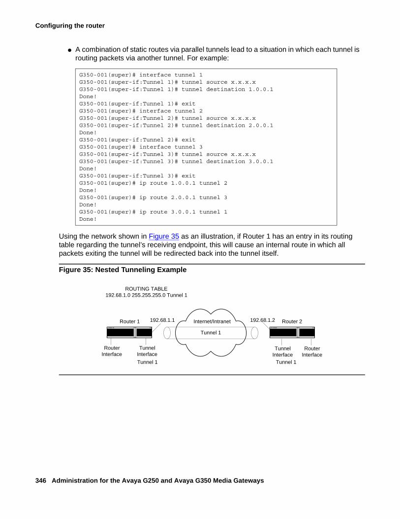
Configuring the router
346 Administration for the Avaya G250 and Avaya G350 Media Gateways
● A combination of static routes via parallel tunnels lead to a situation in which each tunnel is routing packets via another tunnel. For example:
Using the network shown in Figure 35 as an illustration, if Router 1 has an entry in its routing table regarding the tunnel’s receiving endpoint, this will cause an internal route in which all packets exiting the tunnel will be redirected back into the tunnel itself.
Figure 35: Nested Tunneling Example
G350-001(super)# interface tunnel 1G350-001(super-if:Tunnel 1)# tunnel source x.x.x.xG350-001(super-if:Tunnel 1)# tunnel destination 1.0.0.1Done!G350-001(super-if:Tunnel 1)# exitG350-001(super)# interface tunnel 2G350-001(super-if:Tunnel 2)# tunnel source x.x.x.xG350-001(super-if:Tunnel 2)# tunnel destination 2.0.0.1Done!G350-001(super-if:Tunnel 2)# exitG350-001(super)# interface tunnel 3G350-001(super-if:Tunnel 3)# tunnel source x.x.x.xG350-001(super-if:Tunnel 3)# tunnel destination 3.0.0.1Done!G350-001(super-if:Tunnel 3)# exitG350-001(super)# ip route 1.0.0.1 tunnel 2Done!G350-001(super)# ip route 2.0.0.1 tunnel 3Done!G350-001(super)# ip route 3.0.0.1 tunnel 1Done!
Tunnel 1
ROUTING TABLE192.68.1.0 255.255.255.0 Tunnel 1
Router 1 Router 2Internet/Intranet192.68.1.1 192.68.1.2
RouterInterface
TunnelInterface
TunnelInterface
RouterInterface
Tunnel 1 Tunnel 1
Configuring GRE tunneling
Issue 2 February 2006 347
The following are recommended ways to avoid nested tunneling:
● Announce policy.
Configure a policy rule on the receiving tunnel endpoint (router 2) that will cause the receiving endpoint to block advertisements of the source network (192.68.1.0) in its routing updates. This will prevent the source endpoint (router 1) from learning the route. This solution is for nested tunneling caused by RIP. For example, using the network shown in Figure 35 as an illustration, you would configure the following policy rule on router 2 and activate it on the router RIP with the matching interface:
● Accept policy.
Configure a policy rule on the source tunnel endpoint (router 1) that will cause the source endpoint to not accept routing updates that include the source network (192.68.1.0). This solution is for nested tunneling caused by RIP. For example, using the network shown in Figure 35 as an illustration, you would configure the following policy rule on router 1 and activate it on the router RIP with the matching interface:
● Static route.
Configure a static rule on router 1 telling it the route for packets destined to the tunnel’s receiving endpoint (192.68.1.2). This route should be configured with a high route preference. For example:
G350-001(super)# ip distribution access-list-name 1 "list #1"Done!G350-001(super)# ip distribution access-default-action 1 default-action-permitDone!G350-001(super)# ip distribution access-list 1 10 "deny" 192.68.1.0 0.0.0.255Done!G350-001(super)# router ripG350-001(super router:rip)# distribution-list 1 out FastEthernet 10/2Done!G350-001(super router:rip)# exitG350-001(super)#
G350-001(super)# ip distribution access-list-name 1 "list #1"Done!G350-001(super)# ip distribution access-default-action 1 default-action-permitDone!G350-001(super)# ip distribution access-list 1 10 "deny" 192.68.1.0 0.0.0.255Done!G350-001(super)# router ripG350-001(super router:rip)# distribution-list 1 in FastEthernet 10/2Done!G350-001(super router:rip)# exitG350-001(super)#
G350-001(super)# ip route 192.68.1.2 255.255.0.0 192.68.1.3 high permanentDone!G350-001(super)#
Configuring the router
348 Administration for the Avaya G250 and Avaya G350 Media Gateways
Optional GRE tunnel featuresYou can configure the following optional features in GRE tunnels:
● keepalive — enables periodic checking to determine if the tunnel is up or down.
● Dynamic MTU discovery — determines and updates the lowest MTU on the current route through the tunnel.
keepalive
The tunnel keepalive feature sends keepalive packets through the tunnel interface to determine whether the tunnel is up or down. This feature enables the tunnel’s source interface to inform the host if the tunnel is down. When the tunnel keepalive feature is not active, if the tunnel is down, the tunnel’s local endpoint continues to attempt to send packets over the tunnel without informing the host that the packets are failing to reach their destination.
Use the keepalive command in the context of the GRE tunnel interface to enable the tunnel keepalive feature. Use the no form of this command to deactivate the feature.
The keepalive command includes the following parameters:
● seconds — the length, in seconds, of the interval at which the source interface sends keepalive packets. The default value is 10.
● retries — the number of retries after which the source interface declares that the tunnel is down. The default value is 3.
The following example configures Tunnel 1 to send keepalive packets every 20 seconds. If the tunnel’s destination interface fails to respond to three consecutive packets, the tunnel’s source interface concludes that the tunnel is down. The source interface continues to send keepalive packets, but until it receives a response from the tunnel’s destination interface, the tunnel informs hosts that send packets to the tunnel that the tunnel is down.
Note:Note: You do not have to configure tunnel keepalive on both sides of the tunnel.
Dynamic MTU discovery
The size of packets that can travel through a GRE tunnel is limited by the lowest MTU of any router along the route through the tunnel. When dynamic MTU discovery is enabled, the tunnel maintains an MTU limit.
G350-001# interface Tunnel 1G350-001(if:Tunnel 1)# keepalive 20 3Done!
Configuring GRE tunneling
Issue 2 February 2006 349
When a large packet is sent from the host with the DF bit on, and a router in the tunnel path has an MTU that is smaller than the size of the packet, since the DF bit is set, the router sends an ICMP unreachable message back in the originator (in this case, the GRE router). The GRE router then updates the tunnel’s MTU limit accordingly. When a packet larger than the MTU arrives at the tunnel, if the packet is marked do not fragment, the tunnel’s source interface sends the packet back to the host requesting the host to fragment the packet. When dynamic MTU discovery is disabled, the tunnel’s source interface marks each packet as may be fragmented, even if the packet’s original setting is do not fragment. For more information on MTU and fragmentation, refer to Overview of fragmentation on page 377.
Use the tunnel path-mtu-discovery command in the context of the GRE tunnel interface to enable dynamic MTU discovery by the tunnel. Use the no form of this command to deactivate the feature.
The tunnel path-mtu-discovery command includes the following parameters:
● age-timer — how long, until the local tunnel endpoint returns the tunnel MTU to its default. The default value of this parameter is 10 minutes.
Setting up a GRE tunnelTo set up a GRE tunnel:
1. Use the interface tunnel command, followed by a number identifying the tunnel, to create the new tunnel interface. If you are changing the parameters of an existing tunnel, use the interface tunnel command, followed by a number identifying the tunnel, to enter the context of the tunnel. For example:
2. In the interface context, use the tunnel source command, followed by the public IP address of the local tunnel endpoint, to set the source address of the tunnel. For example:
3. In the interface context, use the tunnel destination command, followed by the IP address of the remote tunnel endpoint, to set the destination address of the tunnel. For example:
G350-001(super)# interface tunnel 2G350-001(super-if:Tunnel 2)#
G350-001(super-if:Tunnel 2)# tunnel source 70.70.70.2Done!G350-001(super-if:Tunnel 2)#
G350-001(super-if:Tunnel 2)# tunnel destination 20.0.1.1Done!G350-001(super-if:Tunnel 2)#
Configuring the router
350 Administration for the Avaya G250 and Avaya G350 Media Gateways
Note:Note: The Avaya G250/G350 Media Gateway does not check whether the configured
tunnel source IP address is an existing IP address registered with the G250/G350 router.
4. In most cases, it is recommended to configure keepalive in the tunnel so that the tunnel’s source interface can determine and inform the host if the tunnel is down. For more information on keepalive, see keepalive on page 348.
To configure keepalive for a tunnel interface, type the keepalive command in the interface context, followed by the length (in seconds) of the interval at which the source interface sends keepalive packets, and the number of retries necessary in order to declare the tunnel down. The following example configures the tunnel to send a keepalive packet every 20 seconds, and to declare the tunnel down if the source interface sends three consecutive keepalive packets without a response.
5. In most cases, it is recommended to configure dynamic MTU discovery in the tunnel. This prevents fragmentation of packets larger than the tunnel’s MTU. When dynamic MTU discovery is not enabled, the tunnel fragments packets larger than the tunnel’s MTU, even when the packet is marked do not fragment. For more information on dynamic MTU discovery, see Dynamic MTU discovery on page 348.
The following example configures dynamic MTU discovery, with an age timer of 15 minutes.
6. Type the copy running-config startup-config command. This saves the new tunnel interface configuration in the startup configuration file.
For a list of optional GRE tunnel features, refer to Optional GRE tunnel features on page 348. For a list of additional GRE tunnel CLI commands, refer to Additional GRE tunnel parameters on page 351.
G350-001(super-if:Tunnel 2)# keepalive 20 3Done!G350-001(super-if:Tunnel 2)#
G350-001(super-if:Tunnel 2)# tunnel path-mtu-discovery age-timer 15Done!G350-001(super-if:Tunnel 2)#
Configuring GRE tunneling
Issue 2 February 2006 351
Additional GRE tunnel parametersUse the following commands to configure additional GRE tunnel parameters. For more information about these commands, see Avaya G250 and Avaya G350 CLI Reference, 03-300437.
● Use the tunnel checksum command in the context of the GRE tunnel interface to add a checksum to the GRE header of packets traveling through the tunnel. When a checksum is included on one endpoint, the receiving tunnel endpoint performs checksum validation on incoming packets and packets without a valid checksum are discarded. Use the no form of this command to disable checksums.
● Use the tunnel key command in the context of the GRE tunnel interface to enable and set an ID key for the tunnel. Tunnel ID keys are used as a security device. The key must be set to the same value on the tunnel endpoints. Packets without the configured key must be discarded. Use the no form of this command to disable key checking.
● Use the tunnel DSCP command in the context of the GRE tunnel interface to assign a DSCP value to packets traveling through the tunnel. The DSCP value is placed in the packet’s Carrier IP header. You can assign a DSCP value between 0 and 63. If you do not assign a DSCP value, the DSCP value is copied from the packet’s original IP header.
Note:Note: The Carrier IP header identifies the source and destination IP address of the
tunnel.
● Use the tunnel TTL command in the context of the GRE tunnel interface to assign a TTL value to packets traveling through the tunnel. The TTL value is placed in the packet’s Carrier IP header. You can assign a TTL value between 1 and 255. The default tunnel TTL value is 255.
● Use the show interface tunnel command to show interface configuration and statistics for a particular tunnel or all GRE tunnels.
Note:Note: If the tunnel interface is down, the show interface tunnel command
displays the MTU value as not available.
GRE tunnel application exampleThis section provides an example of a GRE tunnel application and its configuration.
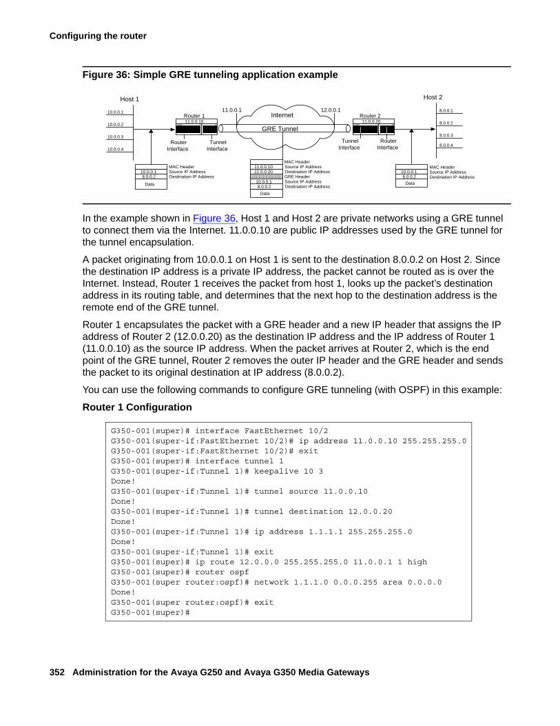
Configuring the router
352 Administration for the Avaya G250 and Avaya G350 Media Gateways
Figure 36: Simple GRE tunneling application example
In the example shown in Figure 36, Host 1 and Host 2 are private networks using a GRE tunnel to connect them via the Internet. 11.0.0.10 are public IP addresses used by the GRE tunnel for the tunnel encapsulation.
A packet originating from 10.0.0.1 on Host 1 is sent to the destination 8.0.0.2 on Host 2. Since the destination IP address is a private IP address, the packet cannot be routed as is over the Internet. Instead, Router 1 receives the packet from host 1, looks up the packet’s destination address in its routing table, and determines that the next hop to the destination address is the remote end of the GRE tunnel.
Router 1 encapsulates the packet with a GRE header and a new IP header that assigns the IP address of Router 2 (12.0.0.20) as the destination IP address and the IP address of Router 1 (11.0.0.10) as the source IP address. When the packet arrives at Router 2, which is the end point of the GRE tunnel, Router 2 removes the outer IP header and the GRE header and sends the packet to its original destination at IP address (8.0.0.2).
You can use the following commands to configure GRE tunneling (with OSPF) in this example:
Router 1 Configuration
G350-001(super)# interface FastEthernet 10/2G350-001(super-if:FastEthernet 10/2)# ip address 11.0.0.10 255.255.255.0G350-001(super-if:FastEthernet 10/2)# exitG350-001(super)# interface tunnel 1G350-001(super-if:Tunnel 1)# keepalive 10 3Done!G350-001(super-if:Tunnel 1)# tunnel source 11.0.0.10Done!G350-001(super-if:Tunnel 1)# tunnel destination 12.0.0.20Done!G350-001(super-if:Tunnel 1)# ip address 1.1.1.1 255.255.255.0Done!G350-001(super-if:Tunnel 1)# exitG350-001(super)# ip route 12.0.0.0 255.255.255.0 11.0.0.1 1 highG350-001(super)# router ospfG350-001(super router:ospf)# network 1.1.1.0 0.0.0.255 area 0.0.0.0Done!G350-001(super router:ospf)# exitG350-001(super)#
Internet
GRE Tunnel
Host 1
RouterInterface
TunnelInterface
Router 1
MAC HeaderSource IP AddressDestination IP Address
Data
8.0.0.210.0.0.1
10.0.0.1
10.0.0.2
10.0.0.3
10.0.0.4
TunnelInterface
Router 2
Data8.0.0.2
10.0.0.1
Host 2
MAC HeaderSource IP AddressDestination IP Address
8.0.0.1
8.0.0.2
8.0.0.3
8.0.0.4
11.0.0.10
Data8.0.0.2
10.0.0.1GRE HeaderSource IP AddressDestination IP Address
11.0.0.2011.0.0.10
MAC HeaderSource IP AddressDestination IP Address
11.0.0.20
RouterInterface
11.0.0.1 12.0.0.1
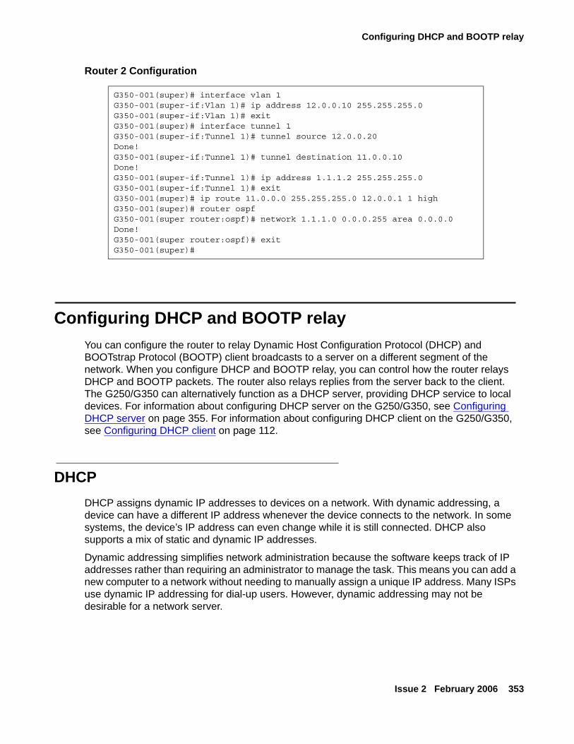
Configuring DHCP and BOOTP relay
Issue 2 February 2006 353
Router 2 Configuration
Configuring DHCP and BOOTP relayYou can configure the router to relay Dynamic Host Configuration Protocol (DHCP) and BOOTstrap Protocol (BOOTP) client broadcasts to a server on a different segment of the network. When you configure DHCP and BOOTP relay, you can control how the router relays DHCP and BOOTP packets. The router also relays replies from the server back to the client. The G250/G350 can alternatively function as a DHCP server, providing DHCP service to local devices. For information about configuring DHCP server on the G250/G350, see Configuring DHCP server on page 355. For information about configuring DHCP client on the G250/G350, see Configuring DHCP client on page 112.
DHCPDHCP assigns dynamic IP addresses to devices on a network. With dynamic addressing, a device can have a different IP address whenever the device connects to the network. In some systems, the device’s IP address can even change while it is still connected. DHCP also supports a mix of static and dynamic IP addresses.
Dynamic addressing simplifies network administration because the software keeps track of IP addresses rather than requiring an administrator to manage the task. This means you can add a new computer to a network without needing to manually assign a unique IP address. Many ISPs use dynamic IP addressing for dial-up users. However, dynamic addressing may not be desirable for a network server.
G350-001(super)# interface vlan 1G350-001(super-if:Vlan 1)# ip address 12.0.0.10 255.255.255.0G350-001(super-if:Vlan 1)# exitG350-001(super)# interface tunnel 1G350-001(super-if:Tunnel 1)# tunnel source 12.0.0.20Done!G350-001(super-if:Tunnel 1)# tunnel destination 11.0.0.10Done!G350-001(super-if:Tunnel 1)# ip address 1.1.1.2 255.255.255.0G350-001(super-if:Tunnel 1)# exitG350-001(super)# ip route 11.0.0.0 255.255.255.0 12.0.0.1 1 highG350-001(super)# router ospfG350-001(super router:ospf)# network 1.1.1.0 0.0.0.255 area 0.0.0.0Done!G350-001(super router:ospf)# exitG350-001(super)#
Configuring the router
354 Administration for the Avaya G250 and Avaya G350 Media Gateways
BOOTPBOOTP is an Internet protocol that allows a diskless workstation to discover the following:
● Its own IP address
● The IP address of a BOOTP server on the network
● A file to be loaded into memory to boot the workstation
BOOTP allows the workstation to boot without requiring a hard disk or diskette drive. It is used when the user or station location changes frequently. The protocol is defined by RFC 951.
DHCP/BOOTP relayThe Avaya G250/G350 Media Gateway supports the DHCP/BOOTP relay agent function. This is an application that accepts DHCP/BOOTP requests that are broadcast on one VLAN. The application sends them to a DHCP/BOOTP server. That server connects to another VLAN or a server that might be located across one or more routers that might otherwise not get the broadcast request. The relay agent handles the DHCP/BOOTP replies as well. The relay agent transmits the replies to the client directly or as broadcast, according to a flag in the reply message.
Note:Note: The same DHCP/BOOTP relay agent serves both the BOOTP and DHCP
protocols.
When there is more than one IP interface on a VLAN, the G250/G350 chooses the lowest IP address on this VLAN when relaying DHCP/BOOTP requests. The DHCP/BOOTP server then uses this address to decide the network from which to allocate the address. When there are multiple networks configured, the G250/G350 performs a round-robin selection process.
When the DHCP/BOOTP server is configured to allocate addresses only from a single subnetwork among the different subnetworks defined on the VLAN, you might need to configure the G250/G350 with the relay address on that subnet so the DHCP/BOOTP server can accept the request.
DHCP/BOOTP Relay in G250/G350 is configurable per VLAN and allows for two DHCP/BOOTP servers to be specified. In this case, the G250/G350 duplicates each request, and sends it to both servers. This duplication provides redundancy and prevents the failure of a single server from blocking hosts from loading. You can enable or disable DHCP/BOOTP Relay in G250/G350.
Configuring DHCP server
Issue 2 February 2006 355
DHCP/BOOTP relay commandsUse the following commands to configure DHCP relay and BOOTP relay:
● Use the ip bootp-dhcp network command to select the network from which the BOOTP/DHCP server should allocate an address. This command is required only when there are multiple IP interfaces over the VLAN. Use the no form of this command to restore the default value. You must be in interface context to use this command.
● Use the ip bootp-dhcp relay command to enable relaying of BOOTP and DHCP requests to the BOOTP/DHCP server. Use the no form of this command to disable relaying of BOOTP and DHCP requests. You must be in general context to use this command.
● Use the ip bootp-dhcp server command to add a BOOTP/DHCP server to handle BOOTP/DHCP requests received by this interface. A maximum of two servers can be added to a single interface. Use the no form of this command to remove a server. You must be in interface context to use this command.
Configuring DHCP serverThe G250/G350 supports DHCP server. DHCP server is a protocol for automatically assigning IP addresses and other configuration parameters to clients on a TCP/IP network. DHCP server minimizes the maintenance of a network of, among other things, IP telephones and PCs, by removing the need to assign and maintain IP addresses and other parameters for each device on the network individually.Since a DHCP server can be configured on the G250/G350, local branch devices are not dependant on receiving configuration parameters over the WAN from a remote DHCP server and therefore can be assigned IP configuration parameters in case of WAN failure.The G250/G350 supports the following DHCP server features:
● Up to 32 DHCP pools
● Up to 120 users
● Up to 256 IP addresses for all DHCP pools together
● Automatic and reservation pools
● Standard DHCP options and IP phone and wireless special options
● Vendor specific information option
● DHCP relay packets
● Global statistics
● Syslog/traps for special events
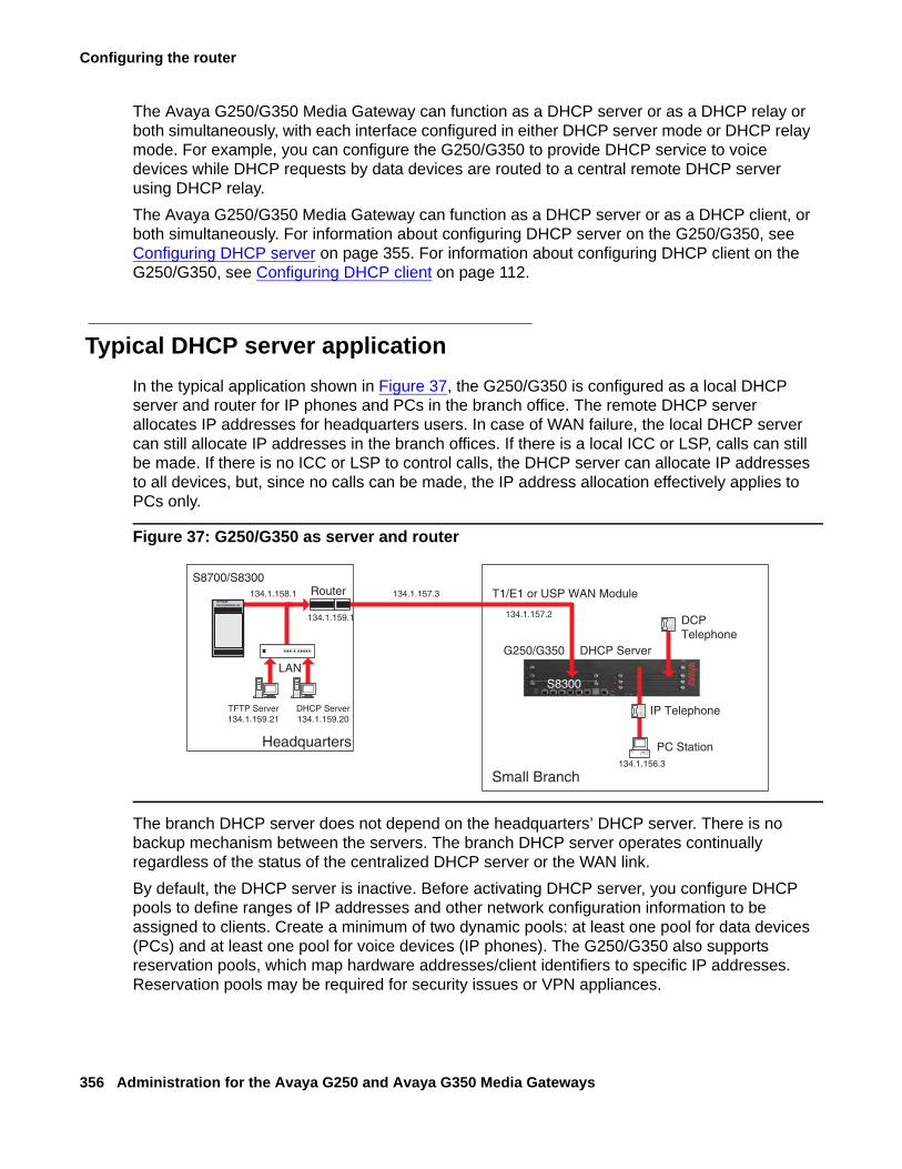
Configuring the router
356 Administration for the Avaya G250 and Avaya G350 Media Gateways
The Avaya G250/G350 Media Gateway can function as a DHCP server or as a DHCP relay or both simultaneously, with each interface configured in either DHCP server mode or DHCP relay mode. For example, you can configure the G250/G350 to provide DHCP service to voice devices while DHCP requests by data devices are routed to a central remote DHCP server using DHCP relay.The Avaya G250/G350 Media Gateway can function as a DHCP server or as a DHCP client, or both simultaneously. For information about configuring DHCP server on the G250/G350, see Configuring DHCP server on page 355. For information about configuring DHCP client on the G250/G350, see Configuring DHCP client on page 112.
Typical DHCP server applicationIn the typical application shown in Figure 37, the G250/G350 is configured as a local DHCP server and router for IP phones and PCs in the branch office. The remote DHCP server allocates IP addresses for headquarters users. In case of WAN failure, the local DHCP server can still allocate IP addresses in the branch offices. If there is a local ICC or LSP, calls can still be made. If there is no ICC or LSP to control calls, the DHCP server can allocate IP addresses to all devices, but, since no calls can be made, the IP address allocation effectively applies to PCs only.
Figure 37: G250/G350 as server and router
The branch DHCP server does not depend on the headquarters’ DHCP server. There is no backup mechanism between the servers. The branch DHCP server operates continually regardless of the status of the centralized DHCP server or the WAN link.By default, the DHCP server is inactive. Before activating DHCP server, you configure DHCP pools to define ranges of IP addresses and other network configuration information to be assigned to clients. Create a minimum of two dynamic pools: at least one pool for data devices (PCs) and at least one pool for voice devices (IP phones). The G250/G350 also supports reservation pools, which map hardware addresses/client identifiers to specific IP addresses. Reservation pools may be required for security issues or VPN appliances.
d
/XFHQW7HFKQRORJLHV
�
S8700/S8300
Headquarters
134.1.159.1
LAN
DHCP Server134.1.159.20
Router
Small Branch
134.1.157.3
G250/G350
T1/E1 or USP WAN Module
IP Telephone
PC Station
TFTP Server134.1.159.21
134.1.158.1
134.1.156.3
S8300
134.1.157.2DCPTelephone
DHCP Server
Configuring DHCP server
Issue 2 February 2006 357
Overlap between pools is not allowed. You cannot configure a reservation pool on an IP address that falls within the range of another pool.
DHCP server CLI configurationTo configure DHCP server on the G250/G350:
1. Use the ip dhcp pool command, followed by a number from 1 to 32, to create a DHCP pool.
2. Use the name command to configure the pool’s name.
3. Configure a range of available IP addresses that the DHCP server may assign to clients, using start-ip-addr to set the start IP address of the range and end-ip-addr to set the end IP address of the range. Consider the following:
● For a manual/reservation pool, set identical IP addresses for the start and end IP addresses.
● The start IP address and end IP address must be on the same network according to the subnet mask.
● The start IP address must be lower than the end IP address.
● The combined number of IP addresses in all pools must not exceed 256 addresses.
● The start IP address and end IP address can be in the range of up to 223.255.255.255.
● The start IP address and end IP address may not be network/broadcast addresses according to the subnet mask.
4. Use the subnet-mask command to configure the subnet mask of the pool.
5. Use the lease command to configure the lease period for IP address assignment. By default, the lease is eight days.
6. For a manual/reservation pool, use the client-identifier command to reserve the pool’s IP address for assignment to a specific client. To configure a reservation, the start IP address and end IP address must be identical. You cannot configure more than one reservation on a single pool.
7. Configure DHCP options for the pool, if required. See Configuring Options on page 358 and, for vendor specific options, Configuring vendor-specific options on page 359.
8. Repeat steps 1-7 to configure as many DHCP pools as you require. You can configure up to 32 DHCP pools. By default, all pools are inactive until you activate them. This enables you to modify each pool’s configuration without affecting network devices.
9. Activate each of the DHCP pools you configured, using the ic dhcp activate pool command in general context, followed by the pool number.
10. Use the ip dhcp-server command to activate DHCP server. DHCP server is now active. If you change the pool configuration, it is recommended to do so while the pool is active.
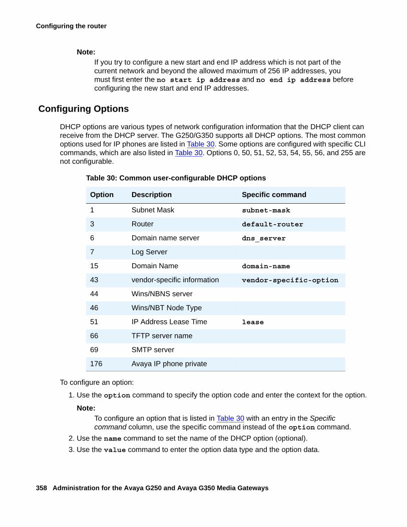
Configuring the router
358 Administration for the Avaya G250 and Avaya G350 Media Gateways
Note:Note: If you try to configure a new start and end IP address which is not part of the
current network and beyond the allowed maximum of 256 IP addresses, you must first enter the no start ip address and no end ip address before configuring the new start and end IP addresses.
Configuring Options
DHCP options are various types of network configuration information that the DHCP client can receive from the DHCP server. The G250/G350 supports all DHCP options. The most common options used for IP phones are listed in Table 30. Some options are configured with specific CLI commands, which are also listed in Table 30. Options 0, 50, 51, 52, 53, 54, 55, 56, and 255 are not configurable.
To configure an option:
1. Use the option command to specify the option code and enter the context for the option.
Note:Note: To configure an option that is listed in Table 30 with an entry in the Specific
command column, use the specific command instead of the option command. 2. Use the name command to set the name of the DHCP option (optional).3. Use the value command to enter the option data type and the option data.
Table 30: Common user-configurable DHCP options
Option Description Specific command
1 Subnet Mask subnet-mask
3 Router default-router
6 Domain name server dns_server
7 Log Server
15 Domain Name domain-name
43 vendor-specific information vendor-specific-option
44 Wins/NBNS server
46 Wins/NBT Node Type
51 IP Address Lease Time lease
66 TFTP server name
69 SMTP server
176 Avaya IP phone private
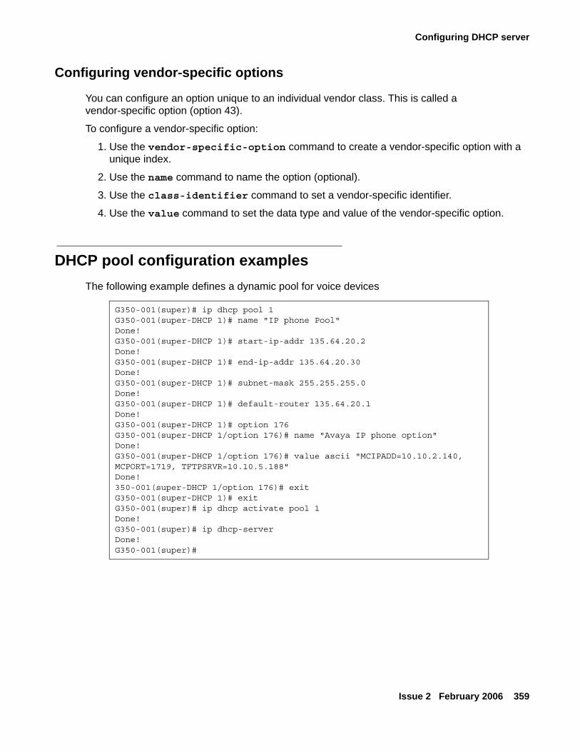
Configuring DHCP server
Issue 2 February 2006 359
Configuring vendor-specific options
You can configure an option unique to an individual vendor class. This is called a vendor-specific option (option 43).
To configure a vendor-specific option:
1. Use the vendor-specific-option command to create a vendor-specific option with a unique index.
2. Use the name command to name the option (optional).
3. Use the class-identifier command to set a vendor-specific identifier.
4. Use the value command to set the data type and value of the vendor-specific option.
DHCP pool configuration examplesThe following example defines a dynamic pool for voice devices
G350-001(super)# ip dhcp pool 1G350-001(super-DHCP 1)# name "IP phone Pool"Done!G350-001(super-DHCP 1)# start-ip-addr 135.64.20.2Done!G350-001(super-DHCP 1)# end-ip-addr 135.64.20.30Done!G350-001(super-DHCP 1)# subnet-mask 255.255.255.0Done!G350-001(super-DHCP 1)# default-router 135.64.20.1Done!G350-001(super-DHCP 1)# option 176G350-001(super-DHCP 1/option 176)# name "Avaya IP phone option"Done!G350-001(super-DHCP 1/option 176)# value ascii "MCIPADD=10.10.2.140, MCPORT=1719, TFTPSRVR=10.10.5.188"Done!350-001(super-DHCP 1/option 176)# exitG350-001(super-DHCP 1)# exitG350-001(super)# ip dhcp activate pool 1Done!G350-001(super)# ip dhcp-serverDone!G350-001(super)#
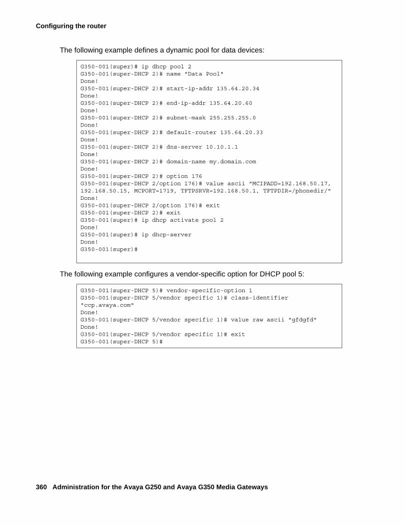
Configuring the router
360 Administration for the Avaya G250 and Avaya G350 Media Gateways
The following example defines a dynamic pool for data devices:
The following example configures a vendor-specific option for DHCP pool 5:
G350-001(super)# ip dhcp pool 2G350-001(super-DHCP 2)# name "Data Pool"Done!G350-001(super-DHCP 2)# start-ip-addr 135.64.20.34Done!G350-001(super-DHCP 2)# end-ip-addr 135.64.20.60Done!G350-001(super-DHCP 2)# subnet-mask 255.255.255.0Done!G350-001(super-DHCP 2)# default-router 135.64.20.33Done!G350-001(super-DHCP 2)# dns-server 10.10.1.1Done!G350-001(super-DHCP 2)# domain-name my.domain.comDone!G350-001(super-DHCP 2)# option 176G350-001(super-DHCP 2/option 176)# value ascii "MCIPADD=192.168.50.17, 192.168.50.15, MCPORT=1719, TFTPSRVR=192.168.50.1, TFTPDIR=/phonedir/"Done!G350-001(super-DHCP 2/option 176)# exitG350-001(super-DHCP 2)# exitG350-001(super)# ip dhcp activate pool 2Done!G350-001(super)# ip dhcp-serverDone!G350-001(super)#
G350-001(super-DHCP 5)# vendor-specific-option 1G350-001(super-DHCP 5/vendor specific 1)# class-identifier "ccp.avaya.com"Done!G350-001(super-DHCP 5/vendor specific 1)# value raw ascii "gfdgfd"Done!G350-001(super-DHCP 5/vendor specific 1)# exitG350-001(super-DHCP 5)#
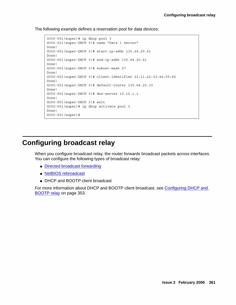
Configuring broadcast relay
Issue 2 February 2006 361
The following example defines a reservation pool for data devices:
Configuring broadcast relayWhen you configure broadcast relay, the router forwards broadcast packets across interfaces. You can configure the following types of broadcast relay:
● Directed broadcast forwarding
● NetBIOS rebroadcast
● DHCP and BOOTP client broadcast
For more information about DHCP and BOOTP client broadcast, see Configuring DHCP and BOOTP relay on page 353.
G350-001(super)# ip dhcp pool 3G350-001(super-DHCP 3)# name "Data 1 Server"Done!G350-001(super-DHCP 3)# start-ip-addr 135.64.20.61Done!G350-001(super-DHCP 3)# end-ip-addr 135.64.20.61Done!G350-001(super-DHCP 3)# subnet-mask 27Done!G350-001(super-DHCP 3)# client-identifier 01:11:22:33:44:55:66Done!G350-001(super-DHCP 3)# default-router 135.64.20.33Done!G350-001(super-DHCP 3)# dns-server 10.10.1.1Done!G350-001(super-DHCP 3)# exitG350-001(super)# ip dhcp activate pool 3Done!G350-001(super)#
Configuring the router
362 Administration for the Avaya G250 and Avaya G350 Media Gateways
Directed broadcast forwardingA directed broadcast is an IP packet whose destination address is the broadcast address of a network or subnet. A directed broadcast causes every host on the network to respond. You can use directed broadcasts to obtain a list of all active hosts on the network. A hostile user can exploit directed broadcasts to launch a denial-of-service attack on the network. For each interface on the Avaya G250/G350 Media Gateway, you can configure whether the G250/G350 forwards directed broadcast packets to the network address or subnet mask address of the interface.
Use the ip directed-broadcast command to enable directed broadcast forwarding on an interface. Use the no form of this command to disable directed broadcast forwarding on an interface.
NetBIOS rebroadcastNetwork Basic Input Output System (NetBIOS) is a protocol for sharing resources among desktop computers on a LAN. You can configure the Avaya G250/G350 Media Gateway to relay NetBIOS UDP broadcast packets. This feature is used for applications such as WINS that use broadcast but might need to communicate with stations on other subnetworks or VLANs.
Configuration is performed on a per-interface basis. A NetBIOS broadcast packet arrives from an interface on which NetBIOS rebroadcast is enabled. The packet is distributed to all other interfaces configured to rebroadcast NetBIOS.
If the NetBIOS packet is a net-directed broadcast, for example, 149.49.255.255, the packet is relayed to all other interfaces on the list, and the IP destination of the packet is replaced by the appropriate interface broadcast address.
If the NetBIOS broadcast packet is a limited broadcast, for example, 255.255.255.255, it is relayed to all VLANs on which there are NetBIOS-enabled interfaces. In that case, the destination IP address remains the limited broadcast address.
Use the ip netbios-rebroadcast both command to enable NetBIOS rebroadcasts on an interface. Use the ip netbios-rebroadcast disable command to disable NetBIOS rebroadcasts on an interface.
Configuring the ARP table
Issue 2 February 2006 363
Configuring the ARP tableWhen you configure the ARP table, you can:
● View information about the ARP table
● Add entries to the ARP table
● Delete entries from the ARP table
● Configure the ARP timeout
Note:Note: To change an entry in the ARP table, delete the entry and add it back with revised
parameters.
Overview of ARPIP logical network addresses are independent of physical addresses. The physical address must be used to convey data in the form of a frame from one device to another. Therefore, a mechanism is required to acquire a destination device hardware address from its IP address. This mechanism is called ARP (Address Resolution Protocol).
The ARP tableThe ARP table stores pairs of IP and MAC addresses. This storage saves time and communication costs, since the host looks in the ARP table first when transmitting a packet. If the information is not there, then the host sends an ARP Request.
There are two types of entries in the ARP table:
● Static ARP table entries
● Dynamic ARP table entries
Static ARP table entries do not expire. You add static ARP table entries manually with the arp command. For example, to add a static ARP table entry for station 192.168.7.8 with MAC address 00:40:0d:8c:2a:01, use the following command:
G350-001# arp 192.168.7.8 00:40:0d:8c:2a:01
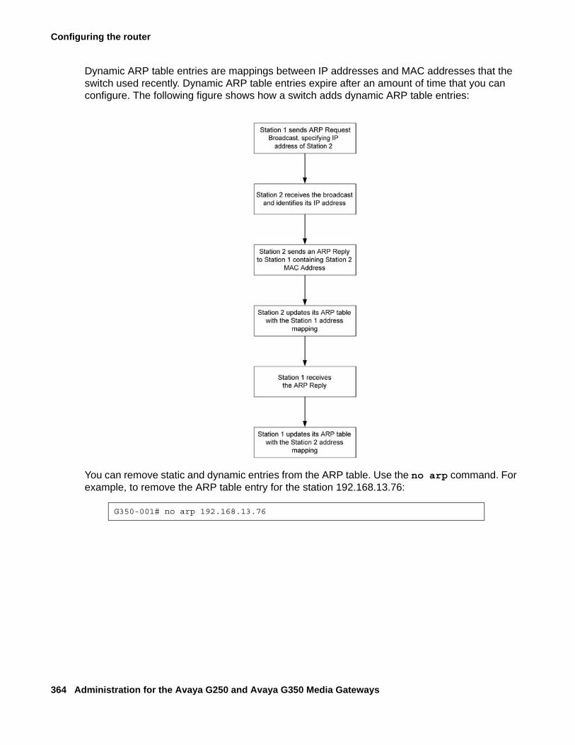
Configuring the router
364 Administration for the Avaya G250 and Avaya G350 Media Gateways
Dynamic ARP table entries are mappings between IP addresses and MAC addresses that the switch used recently. Dynamic ARP table entries expire after an amount of time that you can configure. The following figure shows how a switch adds dynamic ARP table entries:
You can remove static and dynamic entries from the ARP table. Use the no arp command. For example, to remove the ARP table entry for the station 192.168.13.76:
G350-001# no arp 192.168.13.76
Enabling proxy ARP
Issue 2 February 2006 365
ARP table commandsUse the following commands to configure the ARP table. For more information about these commands, see Avaya G250 and Avaya G350 CLI Reference, 03-300437.
● Use the arp command to add a permanent entry to the Address Resolution Protocol (ARP) table. Use the no form of this command to remove either a static entry or a dynamically learned entry from the ARP table.
● Use the arp timeout command to configure the amount of time, in seconds, that an entry remains in the ARP table. Entering the arp timeout command without a time parameter will display the current timeout value. Use the no form of this command to restore the default value (four hours).
● Use the clear arp-cache command to delete all dynamic entries from the ARP table and the IP route cache.
● Use the ip max-arp-entries command to specify the maximum number of ARP table entries allowed in the ARP table. Use the no form of this command to restore the default value.
● Use the show ip arp command to display a list of the ARP resolved MAC to IP addresses in the ARP table.
● Use the show ip reverse-arp command to display the IP address of a host, based on a known MAC address.
Enabling proxy ARPThe G250/G350 supports proxy ARP. Proxy ARP is a technique by which a router provides a false identity when answering ARP requests intended for another device. By falsifying its identify, the router accepts responsibility for routing packets to their true destination.
Proxy ARP can help devices on a subnet to reach remote subnets without the need to configure routing or a default gateway.
To enable proxy ARP on a G250/G350 interface, use the ip proxy-arp command. Use the no form of this command to disable proxy ARP on an interface.
Configuring the router
366 Administration for the Avaya G250 and Avaya G350 Media Gateways
Configuring ICMP errorsYou can control whether the router sends Internet Control Message Protocol (ICMP) error messages. The router sends an ICMP error message to the source of a packet if the router rejects the packet. Use the following commands to configure ICMP errors:
● Use the ip icmp-errors command to set ICMP error messages to ON. Use the no form of this command to set ICMP error messages to OFF.
● Use the show ip icmp command to display the status (enabled or disabled) of ICMP error messages.
Configuring RIPThis section provides information about configuring RIP parameters for router interfaces and contains the following topics:
● RIP overview — an overview of the RIP protocol
● Preventing routing loops in RIP — instructions on how to use RIP features to prevent routing loops
● RIP distribution access lists — instructions on how to configure RIP distribution access lists
● RIP limitations — a description of the limitations on the use of RIP on the G250/G350
● RIP commands — a list and description of CLI commands used to configure RIP
RIP overviewThe Routing Information Protocol (RIP) enables routers to compute the path that an IP packet should follow. Routers exchange routing information using RIP to determine routes that other routers are connected to. OSPF is a newer protocol that serves a similar purpose. For more information about OSPF, see Overview of OSPF on page 370.
You can configure route redistribution between OSPF, RIP, and static routes. With route redistribution, you can configure the G250/G350 to redistribute routes learned from one protocol into the domain of the other routing protocol. For more information, see Route redistribution on page 373.
RIP is a distance vector protocol. The router decides which path to use on distance or the number of intermediate hops. In order for this protocol to work correctly, all the routers, and possibly the nodes, need to gather information on how to reach each destination in the Internet.
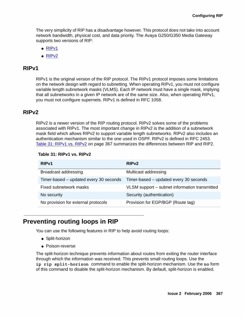
Configuring RIP
Issue 2 February 2006 367
The very simplicity of RIP has a disadvantage however. This protocol does not take into account network bandwidth, physical cost, and data priority. The Avaya G250/G350 Media Gateway supports two versions of RIP:
● RIPv1
● RIPv2
RIPv1
RIPv1 is the original version of the RIP protocol. The RIPv1 protocol imposes some limitations on the network design with regard to subnetting. When operating RIPv1, you must not configure variable length subnetwork masks (VLMS). Each IP network must have a single mask, implying that all subnetworks in a given IP network are of the same size. Also, when operating RIPv1, you must not configure supernets. RIPv1 is defined in RFC 1058.
RIPv2
RIPv2 is a newer version of the RIP routing protocol. RIPv2 solves some of the problems associated with RIPv1. The most important change in RIPv2 is the addition of a subnetwork mask field which allows RIPv2 to support variable length subnetworks. RIPv2 also includes an authentication mechanism similar to the one used in OSPF. RIPv2 is defined in RFC 2453. Table 31: RIPv1 vs. RIPv2 on page 367 summarizes the differences between RIP and RIP2.
Preventing routing loops in RIPYou can use the following features in RIP to help avoid routing loops:
● Split-horizon
● Poison-reverse
The split-horizon technique prevents information about routes from exiting the router interface through which the information was received. This prevents small routing loops. Use the ip rip split-horizon command to enable the split-horizon mechanism. Use the no form of this command to disable the split-horizon mechanism. By default, split-horizon is enabled.
Table 31: RIPv1 vs. RIPv2
RIPv1 RIPv2
Broadcast addressing Multicast addressing
Timer-based – updated every 30 seconds Timer-based – updated every 30 seconds
Fixed subnetwork masks VLSM support – subnet information transmitted
No security Security (authentication)
No provision for external protocols Provision for EGP/BGP (Route tag)
Configuring the router
368 Administration for the Avaya G250 and Avaya G350 Media Gateways
Poison-reverse updates explicitly indicate that a network or subnet is unreachable. Poison-reverse updates are sent to defeat large routing loops. Use the ip rip poison-reverse command to enable split-horizon with poison-reverse on an interface. Use the no form of this command to disable the poison-reverse mechanism.
RIP distribution access listsRIP distribution access lists consist of rules that specify how a router distributes and accepts RIP routing information from other routers. Before sending an update, the router consults an access list to determine if it should include specific routes in the update. When receiving an update, the router first checks a set of rules which apply to incoming updates to determine if it should insert those routes into its routing table. You can assign the rules per interface and per direction.
Up to 99 RIP distribution access lists can be configured on the Avaya G250/G350 Media Gateway.
For example: To configure RIP distribution access list number 10 permitting distribution and learning of network 10.10.0.0:
1. Enter the command: ip distribution access-list 10 1 permit 10.10.0.0 0.0.255.255
The default action of the access list is deny and can be changed using the ip distribution access-default-action command.
Note:Note: Whenever at least one permit rule exists, distributing and learning of all the
remaining networks is denied, unless specifically permitted by another rule.
2. Apply the distribution list created in Step 1 by performing the following procedure within the router rip context:
- Enter the distribution-list 10 in command to apply list number 10 created in Step 1 on all updates received on all interfaces.
- Enter the distribution-list 10 in FastEthernet 10/2 command to apply Access List 10 on updates received on interface ‘FastEthernet 10/2’.
- Enter the distribution-list 10 out command to apply Access List 10 to all advertised updates.
- Enter the distribution-list 10 out ospf command to apply Access List 10 to all advertised updates that were learned from OSPF (redistributed from OSPF into RIP).
If no distribution access list is defined, learning and advertising is allowed for all of the routing information. This is the default.
Configuring RIP
Issue 2 February 2006 369
RIP limitationsConfiguration of RIPv1 and RIPv2 is per IP interface. Configuration must be homogeneous on all routers on each subnetwork. That is, RIPv1 and RIPv2 routers should not be configured on the same subnetwork. However, you can configure different IP interfaces of the G250/G350 with different RIP versions. This configuration is valid as long as all routers on the subnet are configured with the same version.
RIPv2 and RIPv1 are considered the same protocol with regard to redistribution to and from OSPF and static route preferences.
RIP commandsUse the following commands to configure RIP. For more information about these commands, see Avaya G250 and Avaya G350 CLI Reference, 03-300437.
● Use the default-metric command to set the interface RIP route metric value. Use the no form of this command to restore the default value.
● Use the distribution-list command to apply a distribution policy rule for incoming or outgoing routing information in route updates. Use the no form of this command to deactivate the rule.
● Use the ip rip authentication key command to set the authentication string used on the interface. Use the no form of this command to clear the password.
● Use the ip rip authentication mode command to specify the type of authentication used in RIP Version 2 packets. Use the no form of this command to restore the default value, none.
● Use the ip rip default-route-mode command to enable learning of the default route received by the RIP protocol. The default state is talk-listen. Use the no form of this command to disable listening to default routes.
● Use the ip rip poison-reverse command to enable split-horizon with poison-reverse on an interface. Use the no form of this command to disable the poison-reverse mechanism.
● Use the ip rip rip-version command to specify the RIP version running on the interface.
● Use the ip rip send-receive-mode command to set the RIP send and receive modes on an interface. Use the no form of this command to set the RIP to talk, that is, to send reports.
● Use the ip rip split-horizon command to enable the split-horizon mechanism. Use the no form of this command to disable the split-horizon mechanism. By default split-horizon is enabled.
Configuring the router
370 Administration for the Avaya G250 and Avaya G350 Media Gateways
● Use the network command to specify a list of networks on which the RIP is running. Use the no form of this command to remove an entry from the list of networks.
● Use the redistribute command to redistribute routing information from other protocols into RIP. Use the no form of this command to restore the default value, disable redistribution by RIP.
● Use the router rip command to enable RIP and to enter the router configuration context. Use the no form of this command to restore the default value, disabling RIP.
● Use the timers basic command to set RIP timers. Use the no form of this command to set the RIP timers to their default values.
Configuring OSPFThis section provides information about configuring OSPF parameters for router interfaces and contains the following topics:
● Overview of OSPF — an overview of OSPF
● OSPF dynamic cost — a description of OSPF cost calculation, with instructions on how to manually configure the cost of an OSPF interface
● OSPF limitations — a description of the limitations on the use of OSPF on the G250/G350
● OSPF commands — a list and descriptions of CLI commands used to configure OSPF on the G250/G350
Overview of OSPFThe Open Shortest Path First (OSPF) protocol enables routers to compute the path that an IP packet should follow. Routers exchange routing information with OSPF to determine where to send each IP packet on its next hop. RIP is an older protocol that serves a similar purpose. For more information about RIP, see RIP overview on page 366.
OSPF is based on the shortest-path-first or link-state algorithm. It was introduced to overcome the limitations of RIP in increasingly complex network designs. OSPF uses the cost of a path as the criterion for comparing paths. In contrast, RIP uses the number of hops as the criterion for comparing paths. Also, updates are sent when there is a topological change in the network, rather than every 30 seconds as with RIP.
The advantage of shortest-path-first algorithms is that under stable conditions, there are less frequent updates (thereby saving bandwidth). They converge quickly, thus preventing such problems as routing loops and Count-to-Infinity, when routers continuously increment the hop count to a particular network. These algorithms make a stable network. The disadvantage of shortest-path-first algorithms is that they require a lot of CPU power and memory.
Configuring OSPF
Issue 2 February 2006 371
In OSPF, routers use link-state updates to send routing information to all nodes in a network by calculating the shortest path to each node. This calculation is based on a topography of the network constructed by each node. Each router sends that portion of the routing table that describes the state of its own links, and it also sends the complete routing structure (topography).
You can configure route redistribution between OSPF, RIP, and static routes. With route redistribution, you can configure the G250/G350 to redistribute routes learned from one protocol into the domain of the other routing protocol. For more information, see Route redistribution on page 373.
OSPF dynamic costAn OSPF interface on the G250/G350 can dynamically set a Cost. The Cost represents the price assigned to each interface for purposes of determining the shortest path.
By default the OSPF interface Cost is calculated based on the interface bandwidth, according to the following formula:
Cost = 100,000/bandwidth (in kbps)
The result is that the higher the bandwidth, the lower the Cost.
To manually configure the Cost of an OSPF interface, use the ip ospf cost command from the interface context. By using this option, dynamic bandwidth updates do not change the Cost. Use the no ip ospf cost command to return to dynamic cost calculation on an interface.
Use the bandwidth command from the Interface context to manually adjust the interface’s bandwidth If Cost is being determined dynamically, this configured bandwidth and not the actual interface bandwidth, is used to calculate Cost.
OSPF limitationsYou can configure the G250/G350 as an OSPF Autonomous System Boundary Router (ASBR) using route redistribution. The G250/G350 can be installed in the OSPF backbone area (area 0.0.0.0) or in any OSPF area that is part of a multiple areas network. However, the G250/G350 cannot be configured to be an OSPF area border router itself.
The G250/G350 supports the ECMP equal-cost multipath (ECMP) feature which allows load balancing by splitting traffic between several equivalent paths.
While you can activate OSPF with default values for each interface using a single command, you can configure many of the OSPF parameters.
Configuring the router
372 Administration for the Avaya G250 and Avaya G350 Media Gateways
OSPF commandsUse the following commands to configure OSPF. For more information about these commands, see Avaya G250 and Avaya G350 CLI Reference, 03-300437.
● Use the area command to configure the OSPF area ID of the router. Use the no form of the command to delete the OSPF area id.
● Use the default-metric command to set the interface OSPF route metric value. Use the no form of this command to restore the default value.
● Use the ip ospf authentication-key command to configure the interface authentication password. Use the no form of this command to remove the OSPF password.
● Use the ip ospf cost command to configure the interface metric. Use the no form of this command to set the cost to its default value.
● Use the ip ospf dead-interval command to configure the interval before declaring the neighbor as dead. Use the no form of this command to set the dead-interval to its default value.
● Use the ip ospf hello-interval command to specify the time interval between hello packets sent by the router. Use the no form of this command to set the hello-interval to its default value.
● Use the ip ospf network point-to-multipoint command to specify the network type for the interface. Use the no form of the command to return the interface to the default value.
● Use the ip ospf priority command to configure interface priority used in DR election. Use the no form of this command to set the OSPF priority to its default value.
● Use the ip ospf router-id command to configure the router ID. Use the no form of this command to return the router ID to its default value.
● Use the network command to enable OSPF in a network. Use the no form of this command to disable OSPF in a network. The default value is disabled.
● Use the passive-interface command to suppress OSPF routing updates on an interface. This is used to allow interfaces to be flooded into the OSPF domain as OSPF routes rather than external routes.
Note:Note: You must also use the network command, in conjunction with the
passive-interface command, to make the network passive.● Use the redistribute command to redistribute routing information from other protocols
into OSPF. Use the no form of this command to disable redistribution by OSPF.● Use the router ospf command to enable OSPF protocol on the system and to enter the
router configuration context. Use the no form of this command to restore the default value, disable OSPF globally.
Route redistribution
Issue 2 February 2006 373
● Use the show ip ospf command to display general information about OSPF routing.● Use the show ip ospf database command to display lists of information related to the
OSPF database for a specific router.● Use the show ip ospf interface command to display the OSPF-related interface
information.● Use the show ip ospf neighbor command to display OSPF neighbor information on a
per-interface basis.● Use the timers spf command to configure the delay between runs of OSPF’s (SPF)
calculation. Use the no form of this command to restore the default value.
Route redistributionRoute redistribution is the interaction of multiple routing protocols. OSPF and RIP can be operated concurrently in the G250/G350. In this case, you can configure the G250/G350 to redistribute routes learned from one protocol into the domain of the other routing protocol. Similarly, static routes can be redistributed to RIP and OSPF.
Note:Note: Take care when you configure route redistribution. It involves metric changes and
might cause routing loops in the presence of other routes with incompatible schemes for route redistribution and route preferences.
The G250/G350 scheme for metric translation in route redistribution is as follows:
● Static to RIP metric configurable (default 1)
● OSPF internal metric N to RIP metric (default 1)
● OSPF external type 1 metric N to RIP metric (default 1)
● OSPF external type 2 metric N to RIP metric (default 1)
● Static to OSPF external type 2, metric configurable (default 20)
● RIP metric N to OSPF external type 2, metric (default 20)
● Direct to OSPF external type 2, metric (default 20)
By default, the G250/G350 does not redistribute routes between OSPF and RIP. Redistribution from one protocol to the other can be configured. Static routes are, by default, redistributed to RIP and OSPF. The G250/G350 allows the user to globally disable redistribution of static routes to RIP, and separately to globally disable redistribution of static routes to OSPF. In addition you can configure, on a per static route basis, whether the route is to be redistributed to RIP and OSPF, and what metric to use (in the range of 1-15). The default state is to allow the route to be redistributed at metric 1. When static routes are redistributed to OSPF, they are always redistributed as external type 2.
Configuring the router
374 Administration for the Avaya G250 and Avaya G350 Media Gateways
Use the redistribute command in the Router RIP context to configure route redistribution into RIP. Use the redistribute command in the Router OSPF context to configure route redistribution into OSPF.
Export default metricThe Avaya G250/G350 Media Gateway enables you to configure the metric to be used in updates that are redistributed from one routing protocol to another.
In RIP, the default is 1 and the maximum value is 16. In OSPF, the default is 20.
Set this value before redistribution using the default-metric command from within the Router RIP or Router OSPF contexts. This value is used for all types of redistributed routes, regardless of the protocol from which the route was learned.
Configuring VRRPThis section provides information about configuring VRRP to provide router redundancy and load balancing and includes the following topics:
● Overview of VRRP — an overview of the VRRP protocol
● VRRP configuration example — an example of a VRRP configuration with one main router and one backup router
● VRRP commands — a list and descriptions of CLI commands used to configure VRRP
Overview of VRRPVirtual Router Redundancy Protocol (VRRP) is an IETF protocol designed to support redundancy of routers on the LAN and load balancing of traffic. VRRP is open to host stations, making it an ideal option when redundancy, load balancing, and ease of configuration are required.
The concept underlying VRRP is that a router can backup other routers, in addition to performing its primary routing functions. This redundancy is achieved by introducing the concept of a virtual router. A virtual router is a routing entity associated with multiple physical routers. One of the physical routers with which the virtual router is associated performs the routing functions. This router is known as the master router. For each virtual router, VRRP selects a master router. If the selected master router fails, another router is selected as master router.
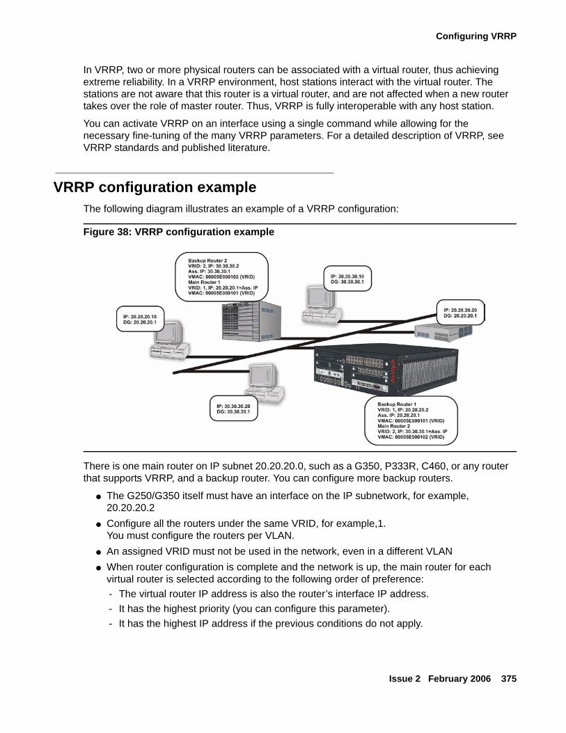
Configuring VRRP
Issue 2 February 2006 375
In VRRP, two or more physical routers can be associated with a virtual router, thus achieving extreme reliability. In a VRRP environment, host stations interact with the virtual router. The stations are not aware that this router is a virtual router, and are not affected when a new router takes over the role of master router. Thus, VRRP is fully interoperable with any host station.
You can activate VRRP on an interface using a single command while allowing for the necessary fine-tuning of the many VRRP parameters. For a detailed description of VRRP, see VRRP standards and published literature.
VRRP configuration exampleThe following diagram illustrates an example of a VRRP configuration:
Figure 38: VRRP configuration example
There is one main router on IP subnet 20.20.20.0, such as a G350, P333R, C460, or any router that supports VRRP, and a backup router. You can configure more backup routers.
● The G250/G350 itself must have an interface on the IP subnetwork, for example, 20.20.20.2
● Configure all the routers under the same VRID, for example,1.You must configure the routers per VLAN.
● An assigned VRID must not be used in the network, even in a different VLAN● When router configuration is complete and the network is up, the main router for each
virtual router is selected according to the following order of preference:- The virtual router IP address is also the router’s interface IP address.- It has the highest priority (you can configure this parameter).- It has the highest IP address if the previous conditions do not apply.
Configuring the router
376 Administration for the Avaya G250 and Avaya G350 Media Gateways
● The virtual router IP address needs to be configured as the default gateway on the stations.
● The Main router advertises a six-byte Virtual MAC address in the format 00.00.5E.00.01.02 VRID as a response to the stations’ ARP requests.
● The redundant router uses a VRRP polling protocol to check the Main router integrity at one second intervals (default). Otherwise, it is idle.
● If the Main router fails, the redundant router that does not receive a response from four consecutive polling requests (default) takes over and starts to advertise the same Virtual MAC for ARP requests. Therefore the stations will not sense any change either in the configured default gateway or at the MAC level.
● VRRP has no provisions for routing database synchronization among the redundant routers. You need to perform this manually if needed.
VRRP commandsUse the following commands to configure VRRP. For more information about these commands, see Avaya G250 and Avaya G350 CLI Reference, 03-300437.
● Use the ip vrrp command to create a virtual router on an interface. Use the no form of this command to delete a virtual router.
● Use the ip vrrp address command to assign an IP address to a virtual router. Use the no form of this command to remove an IP address from a virtual router.
● Use the ip vrrp auth-key command to set the virtual router simple password authentication key for the virtual router ID. Use the no form of this command to disable simple password authentication for the virtual router instance.
● Use the ip vrrp override addr owner command to accept packets addressed to the IP addresses associated with the virtual router, such as ICMP, SNMP, and telnet (if it is not the IP address owner). Use the no form of this command to discard these packets.
● Use the ip vrrp preempt command to configure a router to preempt a lower priority master for the virtual router ID. Use the no form of this command to disable preemption for a virtual router instance. By default, preemption is enabled.
● Use the ip vrrp primary command to set the primary address used as the source address of VRRP packets for the virtual router ID. Use the no form of this command to restore the default primary address for a virtual router instance. By default, the primary address is selected automatically by the device.
● Use the ip vrrp priority command to set the virtual router priority value used when selecting a master router. Use the no form of this command to restore the default value.
● Use the ip vrrp timer command to set the virtual router advertisement timer value for the virtual router ID. Use the no form of this command to restore the default value.
Configuring fragmentation
Issue 2 February 2006 377
● Use the router vrrp command to enable VRRP routing. Use the no form of this command to disable VRRP routing.
● Use the show ip vrrp command to display VRRP information.
Configuring fragmentationThis section provides information about configuring fragmentation on the G250/G350 router and contains the following topics:
● Overview of fragmentation — an overview of fragmentation and reassembly on the G250/G350 router
● Reassembly parameters — a description of the fragmentation parameters you can configure
● Fragmentation commands — a list and descriptions of CLI commands used to configure fragmentation
Overview of fragmentationThe G250/G350 supports IP fragmentation and reassembly. The G250/G350 router can fragment and reassemble IP packets according to RFC 791. This feature allows the router to send and receive large IP packets where the underlying data link protocol constrains the Maximum Transport Unit (MTU).
IP fragmentation involves breaking a datagram into a number of pieces that can be reassembled later. The IP source, destination, identification, total length, and fragment offset fields, along with the more fragment and don’t fragment flags in the IP header, are used for IP fragmentation and reassembly.
IP fragmentation works as follows:
● Each IP packet is divided into fragments.
● Each fragment becomes its own IP packet.
● Each packet has same identifier, source, and destination address.
Fragments are usually not reassembled until final destination. The G250/G350 supports fragmentation of IP packets according to RFC 791, and reassembly of IP packets destined only to its interfaces.

Configuring the router
378 Administration for the Avaya G250 and Avaya G350 Media Gateways
Reassembly parametersReassembly is associated with the following user-configurable parameters:
● Fragment Size — The maximum number of concurrently reassembled packets:Range: 0 to 200. Default: 100.
● Fragment Timeout — The maximum time, in seconds, to wait for a packet to be reassembled:Range: 5 to 120. Default: 10.
● Fragment Chain — The maximum number of fragments allowed per packet:Range: 2 to 2048. Default: 64.
Fragmentation commandsUse the following commands to configure fragmentation and reassembly. For more information about these commands, see Avaya G250 and Avaya G350 CLI Reference, 03-300437.
● Use the clear fragment command to clear the fragment database and restore its default values.
● Use the fragment chain command to set the maximum number of fragments that can comprise a single IP packet destined to the router. Use the no form of this command to set the fragment chain to its default value.
● Use the fragment size command to set the maximum number of fragmented IP packets destined to the router to reassemble at any given time. Use the no form of this command to set the fragment size to its default value.
● Use the fragment timeout command to set the maximum number of seconds to reassemble a fragmented IP packet destined to the router. Use the no form of this command to set the fragment timeout to its default value.
● Use the fragments command to set the treatment for IP fragmentation packets entering on an interface.
● Use the show fragment command to display information regarding fragmented IP packets that are destined to a router.
Issue 2 February 2006 379
Chapter 19: Configuring IPSec VPN
This chapter provides information about configuring IPSec VPN in the G250/G350, and contains the following sections:
● Introduction to IPSec VPN — an introduction to VPN and IPSec technology, including an Overview of IPSec VPN configuration
● Configuring a site-to-site IPSec VPN — instructions on how to configure IPSec VPN in the G250/G350
● IPSec VPN maintenance — instructions on displaying and clearing IPSec VPN data, as well as viewing the IPSec VPN log
● Typical installations — examples of IPSec VPN typical applications
● Check-List for Configuring site-to-site IPSec VPN — A check-list for gathering the information for simple G250 and G350 site-to-site IPSec VPN.
Introduction to IPSec VPNVPN (Virtual Private Network) defines a private secure connection between two nodes on a public network such as the Internet. VPN at the IP level is deployed using IPSec. IPSec (IP Security) is a standards-based set of protocols defined by the IETF that provide privacy, integrity, and authenticity to information transferred across IP networks.
The standard key exchange method employed by IPSec uses the IKE (Internet Key Exchange) protocol to exchange key information between the two nodes (called peers). Each peer maintains SAs (security associations) to maintain the private secure connection. IKE operates in two phases:
● The Phase-1 exchange negotiates an IKE SA.
● The IKE SA created in Phase-1 secures the subsequent Phase-2 exchanges, which in turn generate IPSec SAs.
IPSec SAs secure the actual traffic between the protected networks behind the peers, while the IKE SA only secures the key exchanges that generate the IPSec SAs between the peers.
The G250/G350 IPSec VPN feature is designed to support site-to-site topologies, in which the two peers are gateways.
Note:Note: To configure IPSec VPN, you need at least a basic knowledge of IPSec. The
following can provide a suitable introduction:
- http://www.tcpipguide.com/free/t_IPSecurityIPSecProtocols.htm
Configuring IPSec VPN
380 Administration for the Avaya G250 and Avaya G350 Media Gateways
G250/G350 R2.2 VPN capabilitiesR2.2 VPN supports the following:
● Standards-based IPSec implementation [RFC 2401-RFC 2412...]
● Standard encryption and authentication algorithms for IKE and ESP: DES,TDES, AES (128bit), MD5-HMAC, SHA1-HMAC, IKE DH groups 1 &2
● ESP for data protection and IKE (main mode) for key exchange
● Quick Mode key negotiation with Perfect Forward Secrecy (PFS)
● IKE peer authentication through pre-shared secret
● Multiple IPSec peers (up to 50) for Mesh and hub-and-spoke IPSec topologies
● IPSec protection can be applied on any output port and on many ports concurrently, for maximum installation flexibility
● Per-interface security policy with bypass capability
● IPsec is integrated into the router and can be used with other features such as GRE tunneling
● Random pre-shared key generation service
● Load balancing and resiliency achievable through integration with core routing features such as backup interfaces and GRE
G250/G350 R3.0 VPN capabilitiesR3.0 VPN supports the following, in addition to the R2.2 capabilities:
● Dynamic local peer IP address support through IKE aggressive mode and self-identity FQDN
Note:Note: The G250/G350 can acquire a dynamic IP address through PPPoE or DHCP
● Enhanced remote peer failover support-
● Specifying a hostname rather than IP address for the remote peer, thus allowing for a DNS server to perform a resiliency scheme when providing the IP address mapping.
● Specifying a group of redundant remote peers, rather then a single peer.
● Support for a standard based method called “Dead Peer Detection”, or DPD for short, which enables fast and efficient detection of connection failure at the IKE level.
● Detection of a dead remote peer through object tracking. For information about object tracking, see Object tracking on page 187.
Introduction to IPSec VPN
Issue 2 February 2006 381
● NAT Traversal. The G250/G350 supports both IETF NAT-T methods and the standard method, as well as Avaya’s proprietary method.
● Stronger encryption algorithms – AES with 192 bit key and AES with 256 bit key.
● Support of stronger Diffie-Hellman groups in IKE phase 1 – groups 5 and 14.
● Support of additional Perfect Forward Secrecy (PFS) groups – 5 and 14.
● Transport mode ESP encapsulation, intended for GRE over VPN.
● IP Payload compression (IPPCP) with LZS support.
● Continuous IKE SA and continuous IPSec SA. In this mode, SAs are negotiated as soon as possible, even if no traffic is traversing the connection.
● Configuration MIB, Monitoring MIB, and Traps – as described in avaya-ipsec-mib.my (OID 1.3.6.1.4.1.6889.2.6.1.1).
G250/G350 R3.1 VPN capabilitiesR3.1 VPN supports the following, in addition to the R3.0 capabilities:
● Support for configurations in which the G250/G350 acts as a regional VPN hub for dynamically addressed peers. This is achieved by supporting Aggressive Mode as a responder in an IKE Phase-1 negotiation.
● Enhanced failover scheme for switching back to the primary peer after timeout. When the currently active peer in a peer-group is not the first peer, and that peer has been active for more then 24 hours, if that peer is presumed dead then the active peer pointer is reset back to the first peer in the group.
● Fine tuning of the filtering rules in crypto-lists. This is achieved by enabling filtering of “bypass” rules by various criteria such as protocols and port ranges. Note that “protect” rules filtering has not been extended.
Overview of IPSec VPN configurationThis section provides an overview of the VPN configuration process. Figure 39 summarizes the components you need to define and the order in which you need to define them. Figure 40 describes the relationships among the various VPN components.
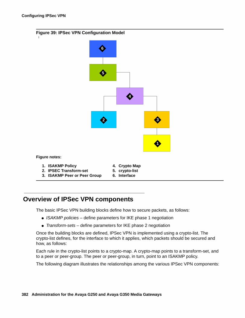
Configuring IPSec VPN
382 Administration for the Avaya G250 and Avaya G350 Media Gateways
Figure 39: IPSec VPN Configuration Modell
Overview of IPSec VPN componentsThe basic IPSec VPN building blocks define how to secure packets, as follows:
● ISAKMP policies – define parameters for IKE phase 1 negotiation
● Transform-sets – define parameters for IKE phase 2 negotiation
Once the building blocks are defined, IPSec VPN is implemented using a crypto-list. The crypto-list defines, for the interface to which it applies, which packets should be secured and how, as follows:
Each rule in the crypto-list points to a crypto-map. A crypto-map points to a transform-set, and to a peer or peer-group. The peer or peer-group, in turn, point to an ISAKMP policy.
The following diagram illustrates the relationships among the various IPSec VPN components:
Figure notes:
1. ISAKMP Policy2. IPSEC Transform-set3. ISAKMP Peer or Peer Group
4. Crypto Map5. crypto-list6. Interface
2
1
3
4
5
6

Introduction to IPSec VPN
Issue 2 February 2006 383
Figure 40: IPSec VPN Components
crypto map 2
crypto map 1 crypto map N
crypto maps pool
Rule 1
Rule 4
Rule 3
Rule 2
Rule N
crypto list
interface
isakmppolicy
N
isakmppolicy
2
isakmppolicy
1
isakmp policies pool
transform-set 1
transform-sets pool
isakmp peer 1
isakmp peer Ntransform-
set N
peer group
peer
isakmp peers pool
peer
isakmp peer-group 1
isakmp peer-group N
peerpeer
isakmp peer-groupspool
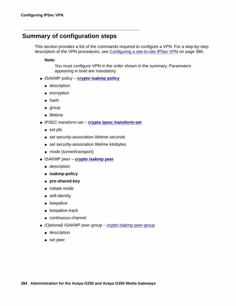
Configuring IPSec VPN
384 Administration for the Avaya G250 and Avaya G350 Media Gateways
Summary of configuration stepsThis section provides a list of the commands required to configure a VPN. For a step-by-step description of the VPN procedures, see Configuring a site-to-site IPSec VPN on page 386.
Note:Note: You must configure VPN in the order shown in the summary. Parameters
appearing in bold are mandatory.
● ISAKMP policy – crypto isakmp policy● description
● encryption
● hash
● group
● lifetime
● IPSEC transform-set – crypto ipsec transform-set● set pfs
● set security-association lifetime seconds
● set security-association lifetime kilobytes
● mode (tunnel/transport)
● ISAKMP peer – crypto isakmp peer● description
● isakmp-policy● pre-shared-key● initiate mode
● self-identity
● keepalive
● keepalive-track
● continuous-channel
● (Optional) ISAKMP peer group – crypto isakmp peer-group
● description
● set peer

Introduction to IPSec VPN
Issue 2 February 2006 385
● Crypto map – crypto map● description
● set transform-set● set peer OR set peer-group● set dscp
● continuous-channel
● IP crypto-list – ip crypto-list● local-address● ip-rule
● description
● source-ip● destination-ip● protect crypto map● ip-protocol
● tcp
● udp
● icmp
● dscp
● fragment
● Access control list – ip access-control-list
● global parameters
● crypto isakmp invalid-spi-recovery
● crypto ipsec nat-transparency udp-encapsulation
● crypto isakmp nat keepalive
● assigning a crypto-list to an interface
● crypto ipsec df-bit
● crypto ipsec minimal-pmtu
● ip crypto-group
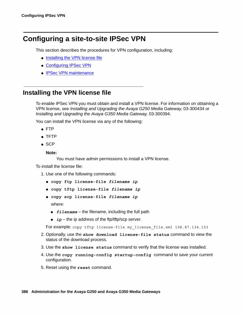
Configuring IPSec VPN
386 Administration for the Avaya G250 and Avaya G350 Media Gateways
Configuring a site-to-site IPSec VPNThis section describes the procedures for VPN configuration, including:
● Installing the VPN license file
● Configuring IPSec VPN
● IPSec VPN maintenance
Installing the VPN license fileTo enable IPSec VPN you must obtain and install a VPN license. For information on obtaining a VPN license, see Installing and Upgrading the Avaya G250 Media Gateway, 03-300434 or Installing and Upgrading the Avaya G350 Media Gateway, 03-300394.
You can install the VPN license via any of the following:
● FTP
● TFTP
● SCP
Note:Note: You must have admin permissions to install a VPN license.
To install the license file:
1. Use one of the following commands:
● copy ftp license-file filename ip
● copy tftp license-file filename ip
● copy scp license-file filename ip
where:
● filename – the filename, including the full path
● ip – the ip address of the ftp/tftp/scp server.
For example: copy tftp license-file my_license_file.xml 198.87.134.153
2. Optionally, use the show download license-file status command to view the status of the download process.
3. Use the show license status command to verify that the license was installed.
4. Use the copy running-config startup-config command to save your current configuration.
5. Reset using the reset command.
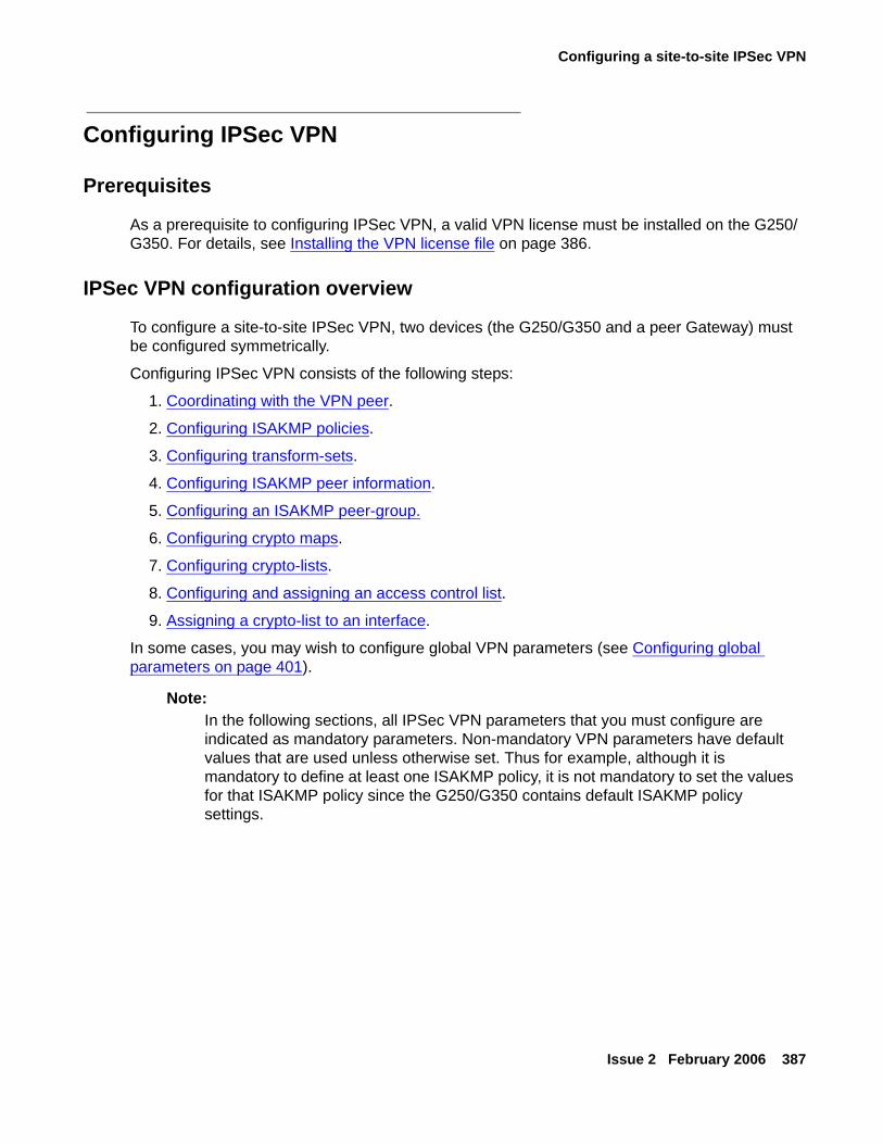
Configuring a site-to-site IPSec VPN
Issue 2 February 2006 387
Configuring IPSec VPN
Prerequisites
As a prerequisite to configuring IPSec VPN, a valid VPN license must be installed on the G250/G350. For details, see Installing the VPN license file on page 386.
IPSec VPN configuration overview
To configure a site-to-site IPSec VPN, two devices (the G250/G350 and a peer Gateway) must be configured symmetrically.
Configuring IPSec VPN consists of the following steps:
1. Coordinating with the VPN peer.
2. Configuring ISAKMP policies.
3. Configuring transform-sets.
4. Configuring ISAKMP peer information.
5. Configuring an ISAKMP peer-group.
6. Configuring crypto maps.
7. Configuring crypto-lists.
8. Configuring and assigning an access control list.
9. Assigning a crypto-list to an interface.
In some cases, you may wish to configure global VPN parameters (see Configuring global parameters on page 401).
Note:Note: In the following sections, all IPSec VPN parameters that you must configure are
indicated as mandatory parameters. Non-mandatory VPN parameters have default values that are used unless otherwise set. Thus for example, although it is mandatory to define at least one ISAKMP policy, it is not mandatory to set the values for that ISAKMP policy since the G250/G350 contains default ISAKMP policy settings.
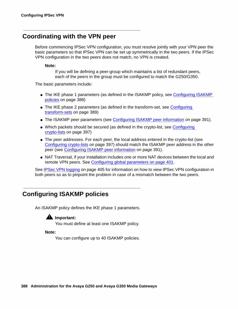
Configuring IPSec VPN
388 Administration for the Avaya G250 and Avaya G350 Media Gateways
Coordinating with the VPN peerBefore commencing IPSec VPN configuration, you must resolve jointly with your VPN peer the basic parameters so that IPSec VPN can be set up symmetrically in the two peers. If the IPSec VPN configuration in the two peers does not match, no VPN is created.
Note:Note: If you will be defining a peer-group which maintains a list of redundant peers,
each of the peers in the group must be configured to match the G250/G350.
The basic parameters include:
● The IKE phase 1 parameters (as defined in the ISAKMP policy, see Configuring ISAKMP policies on page 388)
● The IKE phase 2 parameters (as defined in the transform-set, see Configuring transform-sets on page 389)
● The ISAKMP peer parameters (see Configuring ISAKMP peer information on page 391).
● Which packets should be secured (as defined in the crypto-list, see Configuring crypto-lists on page 397)
● The peer addresses. For each peer, the local address entered in the crypto-list (see Configuring crypto-lists on page 397) should match the ISAKMP peer address in the other peer (see Configuring ISAKMP peer information on page 391).
● NAT Traversal, if your installation includes one or more NAT devices between the local and remote VPN peers. See Configuring global parameters on page 401.
See IPSec VPN logging on page 405 for information on how to view IPSec VPN configuration in both peers so as to pinpoint the problem in case of a mismatch between the two peers.
Configuring ISAKMP policies
An ISAKMP policy defines the IKE phase 1 parameters.
! Important:Important: You must define at least one ISAKMP policy.
Note:Note: You can configure up to 40 ISAKMP policies.
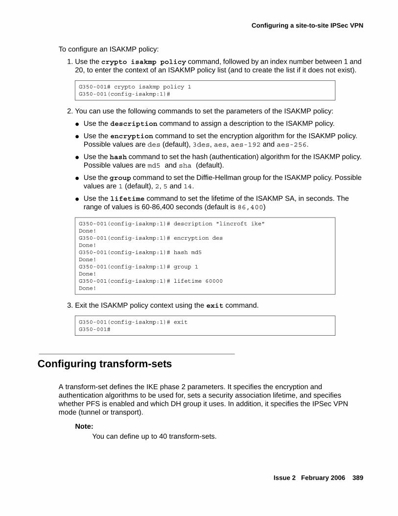
Configuring a site-to-site IPSec VPN
Issue 2 February 2006 389
To configure an ISAKMP policy:
1. Use the crypto isakmp policy command, followed by an index number between 1 and 20, to enter the context of an ISAKMP policy list (and to create the list if it does not exist).
2. You can use the following commands to set the parameters of the ISAKMP policy:
● Use the description command to assign a description to the ISAKMP policy.
● Use the encryption command to set the encryption algorithm for the ISAKMP policy. Possible values are des (default), 3des, aes, aes-192 and aes-256.
● Use the hash command to set the hash (authentication) algorithm for the ISAKMP policy. Possible values are md5 and sha (default).
● Use the group command to set the Diffie-Hellman group for the ISAKMP policy. Possible values are 1 (default), 2, 5 and 14.
● Use the lifetime command to set the lifetime of the ISAKMP SA, in seconds. The range of values is 60-86,400 seconds (default is 86,400)
3. Exit the ISAKMP policy context using the exit command.
Configuring transform-sets
A transform-set defines the IKE phase 2 parameters. It specifies the encryption and authentication algorithms to be used for, sets a security association lifetime, and specifies whether PFS is enabled and which DH group it uses. In addition, it specifies the IPSec VPN mode (tunnel or transport).
Note:Note: You can define up to 40 transform-sets.
G350-001# crypto isakmp policy 1G350-001(config-isakmp:1)#
G350-001(config-isakmp:1)# description "lincroft ike"Done!G350-001(config-isakmp:1)# encryption desDone!G350-001(config-isakmp:1)# hash md5Done!G350-001(config-isakmp:1)# group 1Done!G350-001(config-isakmp:1)# lifetime 60000Done!
G350-001(config-isakmp:1)# exitG350-001#
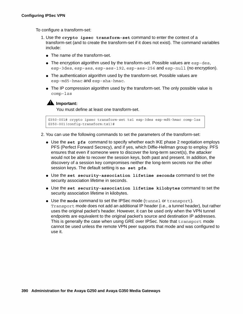
Configuring IPSec VPN
390 Administration for the Avaya G250 and Avaya G350 Media Gateways
To configure a transform-set:
1. Use the crypto ipsec transform-set command to enter the context of a transform-set (and to create the transform-set if it does not exist). The command variables include:
● The name of the transform-set.
● The encryption algorithm used by the transform-set. Possible values are esp-des, esp-3des, esp-aes, esp-aes-192, esp-aes-256 and esp-null (no encryption).
● The authentication algorithm used by the transform-set. Possible values are esp-md5-hmac and esp-sha-hmac.
● The IP compression algorithm used by the transform-set. The only possible value is comp-lzs
! Important:Important: You must define at least one transform-set.
2. You can use the following commands to set the parameters of the transform-set:
● Use the set pfs command to specify whether each IKE phase 2 negotiation employs PFS (Perfect Forward Secrecy), and if yes, which Diffie-Hellman group to employ. PFS ensures that even if someone were to discover the long-term secret(s), the attacker would not be able to recover the session keys, both past and present. In addition, the discovery of a session key compromises neither the long-term secrets nor the other session keys. The default setting is no set pfs.
● Use the set security-association lifetime seconds command to set the security association lifetime in seconds.
● Use the set security-association lifetime kilobytes command to set the security association lifetime in kilobytes.
● Use the mode command to set the IPSec mode (tunnel or transport). Transport mode does not add an additional IP header (i.e., a tunnel header), but rather uses the original packet’s header. However, it can be used only when the VPN tunnel endpoints are equivalent to the original packet’s source and destination IP addresses. This is generally the case when using GRE over IPSec. Note that transport mode cannot be used unless the remote VPN peer supports that mode and was configured to use it.
G350-001# crypto ipsec transform-set ts1 esp-3des esp-md5-hmac comp-lzsG350-001(config-transform:ts1)#
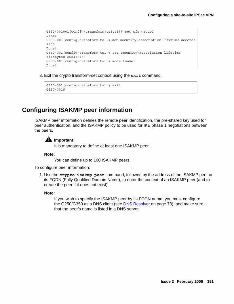
Configuring a site-to-site IPSec VPN
Issue 2 February 2006 391
3. Exit the crypto transform-set context using the exit command.
Configuring ISAKMP peer informationISAKMP peer information defines the remote peer identification, the pre-shared key used for peer authentication, and the ISAKMP policy to be used for IKE phase 1 negotiations between the peers.
! Important:Important: It is mandatory to define at least one ISAKMP peer.
Note:Note: You can define up to 100 ISAKMP peers.
To configure peer information:
1. Use the crypto isakmp peer command, followed by the address of the ISAKMP peer or its FQDN (Fully Qualified Domain Name), to enter the context of an ISAKMP peer (and to create the peer if it does not exist).
Note:Note: If you wish to specify the ISAKMP peer by its FQDN name, you must configure
the G250/G350 as a DNS client (see DNS Resolver on page 73), and make sure that the peer’s name is listed in a DNS server.
G350-001001(config-transform:ts1ts1)# set pfs group2Done!G350-001(config-transform:ts1)# set security-association lifetime seconds 7200Done!G350-001(config-transform:ts1)# set security-association lifetime kilobytes 268435456G350-001(config-transform:ts1)# mode tunnelDone!
G350-001(config-transform:ts1)# exitG350-001#
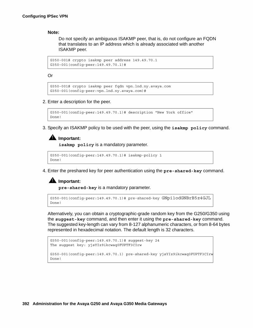
Configuring IPSec VPN
392 Administration for the Avaya G250 and Avaya G350 Media Gateways
Note:Note: Do not specify an ambiguous ISAKMP peer, that is, do not configure an FQDN
that translates to an IP address which is already associated with another ISAKMP peer.
Or
2. Enter a description for the peer.
3. Specify an ISAKMP policy to be used with the peer, using the isakmp policy command.
! Important:Important: isakmp policy is a mandatory parameter.
4. Enter the preshared key for peer authentication using the pre-shared-key command.
! Important:Important: pre-shared-key is a mandatory parameter.
Alternatively, you can obtain a cryptographic-grade random key from the G250/G350 using the suggest-key command, and then enter it using the pre-shared-key command. The suggested key-length can vary from 8-127 alphanumeric characters, or from 8-64 bytes represented in hexadecimal notation. The default length is 32 characters.
G350-001# crypto isakmp peer address 149.49.70.1G350-001(config-peer:149.49.70.1)#
G350-001# crypto isakmp peer fqdn vpn.lnd.ny.avaya.comG350-001(config-peer:vpn.lnd.ny.avaya.com)#
G350-001(config-peer:149.49.70.1)# description "New York office"Done!
G350-001(config-peer:149.49.70.1)# isakmp-policy 1Done!
G350-001(config-peer:149.49.70.1)# pre-shared-key GNpi1odGNBrB5z4GJLDone!
G350-001(config-peer:149.49.70.1)# suggest-key 24The suggest key: yjsYIz9ikcwaq0FUPTF3CIrw
G350-001(config-peer:149.49.70.1) pre-shared-key yjsYIz9ikcwaq0FUPTF3CIrwDone!
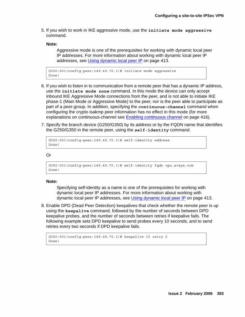
Configuring a site-to-site IPSec VPN
Issue 2 February 2006 393
5. If you wish to work in IKE aggressive mode, use the initiate mode aggressive command.
Note:Note: Aggressive mode is one of the prerequisites for working with dynamic local peer
IP addresses. For more information about working with dynamic local peer IP addresses, see Using dynamic local peer IP on page 413.
6. If you wish to listen in to communication from a remote peer that has a dynamic IP address, use the initiate mode none command. In this mode the device can only accept inbound IKE Aggressive Mode connections from the peer, and is not able to initiate IKE phase-1 (Main Mode or Aggressive Mode) to the peer, nor is the peer able to participate as part of a peer-group. In addition, specifying the continuous-channel command when configuring the crypto isakmp peer information has no effect in this mode (for more explanations on continuous-channel see Enabling continuous channel on page 416).
7. Specify the branch device (G250/G350) by its address or by the FQDN name that identifies the G250/G350 in the remote peer, using the self-identity command.
Or
Note:Note: Specifying self-identity as a name is one of the prerequisites for working with
dynamic local peer IP addresses. For more information about working with dynamic local peer IP addresses, see Using dynamic local peer IP on page 413.
8. Enable DPD (Dead Peer Detection) keepalives that check whether the remote peer is up using the keepalive command, followed by the number of seconds between DPD keepalive probes, and the number of seconds between retries if keepalive fails. The following example sets DPD keepalive to send probes every 10 seconds, and to send retries every two seconds if DPD keepalive fails.
G350-001(config-peer:149.49.70.1)# initiate mode aggressiveDone!
G350-001(config-peer:149.49.70.1)# self-identity addressDone!
G350-001(config-peer:149.49.70.1)# self-identity fqdn vpn.avaya.comDone!
G350-001(config-peer:149.49.70.1)# keepalive 10 retry 2Done!
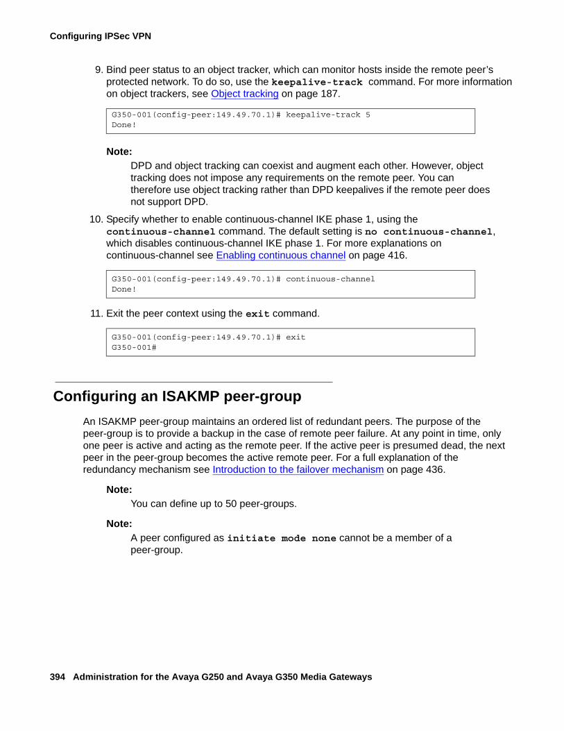
Configuring IPSec VPN
394 Administration for the Avaya G250 and Avaya G350 Media Gateways
9. Bind peer status to an object tracker, which can monitor hosts inside the remote peer’s protected network. To do so, use the keepalive-track command. For more information on object trackers, see Object tracking on page 187.
Note:Note: DPD and object tracking can coexist and augment each other. However, object
tracking does not impose any requirements on the remote peer. You can therefore use object tracking rather than DPD keepalives if the remote peer does not support DPD.
10. Specify whether to enable continuous-channel IKE phase 1, using the continuous-channel command. The default setting is no continuous-channel, which disables continuous-channel IKE phase 1. For more explanations on continuous-channel see Enabling continuous channel on page 416.
11. Exit the peer context using the exit command.
Configuring an ISAKMP peer-groupAn ISAKMP peer-group maintains an ordered list of redundant peers. The purpose of the peer-group is to provide a backup in the case of remote peer failure. At any point in time, only one peer is active and acting as the remote peer. If the active peer is presumed dead, the next peer in the peer-group becomes the active remote peer. For a full explanation of the redundancy mechanism see Introduction to the failover mechanism on page 436.
Note:Note: You can define up to 50 peer-groups.
Note:Note: A peer configured as initiate mode none cannot be a member of a
peer-group.
G350-001(config-peer:149.49.70.1)# keepalive-track 5Done!
G350-001(config-peer:149.49.70.1)# continuous-channelDone!
G350-001(config-peer:149.49.70.1)# exitG350-001#

Configuring a site-to-site IPSec VPN
Issue 2 February 2006 395
To define a peer-group:
1. Use the crypto isakmp peer-group command, followed by the name of a peer-group (a string of up to 110 characters), to enter the context of an ISAKMP peer-group (and to create the peer-group if it does not exist).
.
2. Use the description command to enter a description for the ISAKMP peer-group.
3. Add a peer to the list of peers in the group, using the set peer command.
● Specify the peer’s name or address.
● Optionally enter an index number, specifying the relative position of the peer within the peer-group. If you do not enter an index number, the peer is added at the end of the peer-group list, and is assigned an index following the last peer’s index.
4. Repeat step 3 for every peer you wish to add to the list.
Note:Note: You can define up to a maximum of five peers in a peer-group.
! Important:Important: Each of the peers listed in the peer-group must be configured as an ISAKMP
peer (see Configuring ISAKMP peer information on page 391).
Configuring crypto mapsA crypto map points to a transform-set and to a peer (which in turn points to an ISAKMP policy). If you defined a peer-group, the crypto map can point to the peer-group.The transform-set and ISAKMP policy define how to secure the traffic that matches the ip-rule that points to this crypto map.
! Important:Important: It is mandatory to create at least one crypto map.
Note:Note: You can configure up to 100 crypto maps.
G350-001# crypto isakmp peer-group NY-VPN-groupG350-001(config-peer-grp:NY-VPN-group)#
G350-001(config-peer-grp:NY-VPN-group)# description “Avaya peer group”Done!
G350-001(config-peer-grp:NY-VPN-group)# set peer 149.49.52.135 1Done!
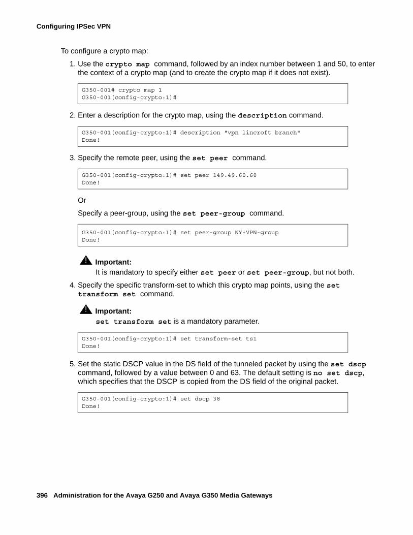
Configuring IPSec VPN
396 Administration for the Avaya G250 and Avaya G350 Media Gateways
To configure a crypto map:
1. Use the crypto map command, followed by an index number between 1 and 50, to enter the context of a crypto map (and to create the crypto map if it does not exist).
2. Enter a description for the crypto map, using the description command.
3. Specify the remote peer, using the set peer command.
Or
Specify a peer-group, using the set peer-group command.
! Important:Important: It is mandatory to specify either set peer or set peer-group, but not both.
4. Specify the specific transform-set to which this crypto map points, using the set transform set command.
! Important:Important: set transform set is a mandatory parameter.
5. Set the static DSCP value in the DS field of the tunneled packet by using the set dscp command, followed by a value between 0 and 63. The default setting is no set dscp, which specifies that the DSCP is copied from the DS field of the original packet.
G350-001# crypto map 1G350-001(config-crypto:1)#
G350-001(config-crypto:1)# description "vpn lincroft branch"Done!
G350-001(config-crypto:1)# set peer 149.49.60.60Done!
G350-001(config-crypto:1)# set peer-group NY-VPN-groupDone!
G350-001(config-crypto:1)# set transform-set ts1Done!
G350-001(config-crypto:1)# set dscp 38Done!
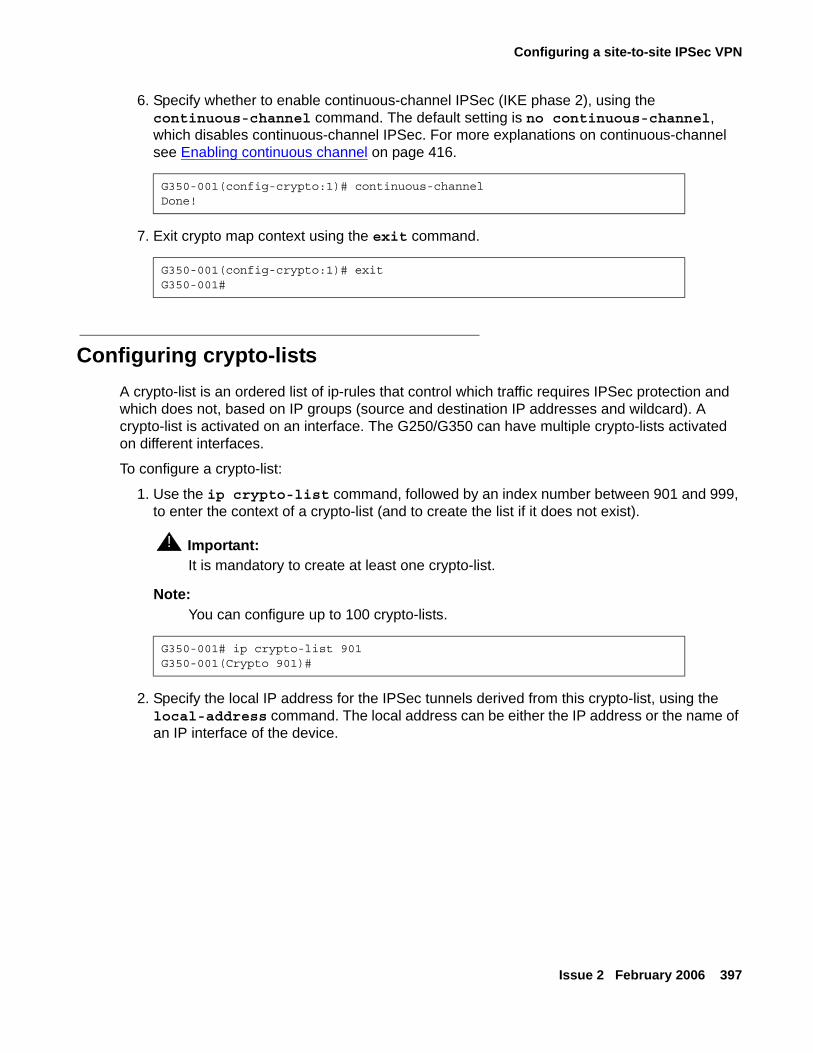
Configuring a site-to-site IPSec VPN
Issue 2 February 2006 397
6. Specify whether to enable continuous-channel IPSec (IKE phase 2), using the continuous-channel command. The default setting is no continuous-channel, which disables continuous-channel IPSec. For more explanations on continuous-channel see Enabling continuous channel on page 416.
7. Exit crypto map context using the exit command.
Configuring crypto-listsA crypto-list is an ordered list of ip-rules that control which traffic requires IPSec protection and which does not, based on IP groups (source and destination IP addresses and wildcard). A crypto-list is activated on an interface. The G250/G350 can have multiple crypto-lists activated on different interfaces.
To configure a crypto-list:
1. Use the ip crypto-list command, followed by an index number between 901 and 999, to enter the context of a crypto-list (and to create the list if it does not exist).
! Important:Important: It is mandatory to create at least one crypto-list.
Note:Note: You can configure up to 100 crypto-lists.
2. Specify the local IP address for the IPSec tunnels derived from this crypto-list, using the local-address command. The local address can be either the IP address or the name of an IP interface of the device.
G350-001(config-crypto:1)# continuous-channelDone!
G350-001(config-crypto:1)# exitG350-001#
G350-001# ip crypto-list 901G350-001(Crypto 901)#
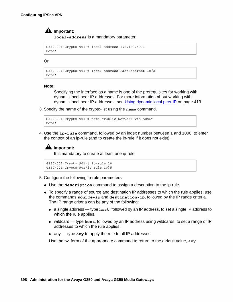
Configuring IPSec VPN
398 Administration for the Avaya G250 and Avaya G350 Media Gateways
! Important:Important: local-address is a mandatory parameter.
Or
Note:Note: Specifying the interface as a name is one of the prerequisites for working with
dynamic local peer IP addresses. For more information about working with dynamic local peer IP addresses, see Using dynamic local peer IP on page 413.
3. Specify the name of the crypto-list using the name command.
4. Use the ip-rule command, followed by an index number between 1 and 1000, to enter the context of an ip-rule (and to create the ip-rule if it does not exist).
! Important:Important: It is mandatory to create at least one ip-rule.
5. Configure the following ip-rule parameters:
● Use the description command to assign a description to the ip-rule.
● To specify a range of source and destination IP addresses to which the rule applies, use the commands source-ip and destination-ip, followed by the IP range criteria. The IP range criteria can be any of the following:
● a single address — type host, followed by an IP address, to set a single IP address to which the rule applies.
● wildcard — type host, followed by an IP address using wildcards, to set a range of IP addresses to which the rule applies.
● any — type any to apply the rule to all IP addresses.
Use the no form of the appropriate command to return to the default value, any.
G350-001(Crypto 901)# local-address 192.168.49.1Done!
G350-001(Crypto 901)# local-address FastEthernet 10/2Done!
G350-001(Crypto 901)# name “Public Network via ADSL”Done!
G350-001(Crypto 901)# ip-rule 10G350-001(Crypto 901/ip rule 10)#
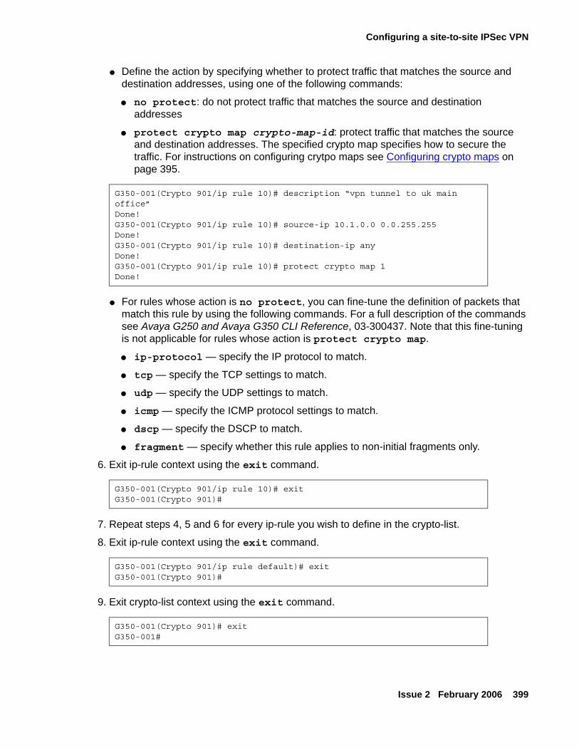
Configuring a site-to-site IPSec VPN
Issue 2 February 2006 399
● Define the action by specifying whether to protect traffic that matches the source and destination addresses, using one of the following commands:
● no protect: do not protect traffic that matches the source and destination addresses
● protect crypto map crypto-map-id: protect traffic that matches the source and destination addresses. The specified crypto map specifies how to secure the traffic. For instructions on configuring crytpo maps see Configuring crypto maps on page 395.
● For rules whose action is no protect, you can fine-tune the definition of packets that match this rule by using the following commands. For a full description of the commands see Avaya G250 and Avaya G350 CLI Reference, 03-300437. Note that this fine-tuning is not applicable for rules whose action is protect crypto map.
● ip-protocol — specify the IP protocol to match.
● tcp — specify the TCP settings to match.
● udp — specify the UDP settings to match.
● icmp — specify the ICMP protocol settings to match.
● dscp — specify the DSCP to match.
● fragment — specify whether this rule applies to non-initial fragments only.
6. Exit ip-rule context using the exit command.
7. Repeat steps 4, 5 and 6 for every ip-rule you wish to define in the crypto-list.
8. Exit ip-rule context using the exit command.
9. Exit crypto-list context using the exit command.
G350-001(Crypto 901/ip rule 10)# description “vpn tunnel to uk main office”Done!G350-001(Crypto 901/ip rule 10)# source-ip 10.1.0.0 0.0.255.255Done!G350-001(Crypto 901/ip rule 10)# destination-ip anyDone!G350-001(Crypto 901/ip rule 10)# protect crypto map 1Done!
G350-001(Crypto 901/ip rule 10)# exitG350-001(Crypto 901)#
G350-001(Crypto 901/ip rule default)# exitG350-001(Crypto 901)#
G350-001(Crypto 901)# exitG350-001#
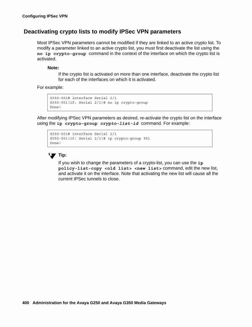
Configuring IPSec VPN
400 Administration for the Avaya G250 and Avaya G350 Media Gateways
Deactivating crypto lists to modify IPSec VPN parameters
Most IPSec VPN parameters cannot be modified if they are linked to an active crypto list. To modify a parameter linked to an active crypto list, you must first deactivate the list using the no ip crypto-group command in the context of the interface on which the crypto list is activated.
Note:Note: If the crypto list is activated on more than one interface, deactivate the crypto list
for each of the interfaces on which it is activated.
For example:
After modifying IPSec VPN parameters as desired, re-activate the crypto list on the interface using the ip crypto-group crypto-list-id command. For example:
Tip:Tip: If you wish to change the parameters of a crypto-list, you can use the ip
policy-list-copy <old list> <new list> command, edit the new list, and activate it on the interface. Note that activating the new list will cause all the current IPSec tunnels to close.
G350-001# interface Serial 2/1G350-001(if: Serial 2/1)# no ip crypto-groupDone!
G350-001# interface Serial 2/1G350-001(if: Serial 2/1)# ip crypto-group 901Done!
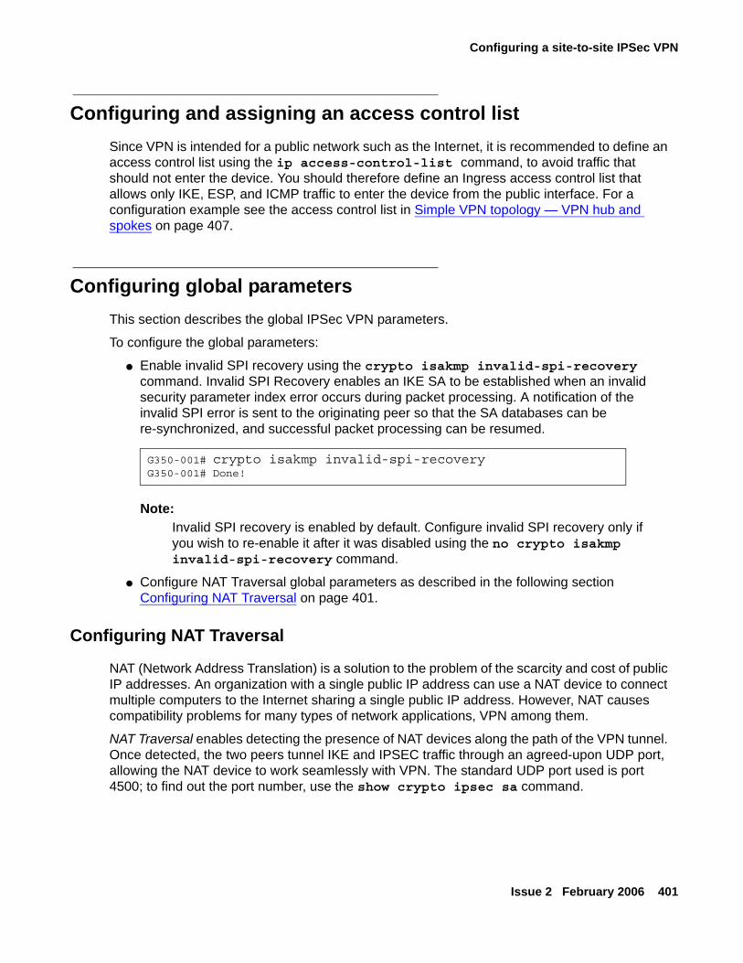
Configuring a site-to-site IPSec VPN
Issue 2 February 2006 401
Configuring and assigning an access control listSince VPN is intended for a public network such as the Internet, it is recommended to define an access control list using the ip access-control-list command, to avoid traffic that should not enter the device. You should therefore define an Ingress access control list that allows only IKE, ESP, and ICMP traffic to enter the device from the public interface. For a configuration example see the access control list in Simple VPN topology — VPN hub and spokes on page 407.
Configuring global parametersThis section describes the global IPSec VPN parameters.
To configure the global parameters:
● Enable invalid SPI recovery using the crypto isakmp invalid-spi-recovery command. Invalid SPI Recovery enables an IKE SA to be established when an invalid security parameter index error occurs during packet processing. A notification of the invalid SPI error is sent to the originating peer so that the SA databases can be re-synchronized, and successful packet processing can be resumed.
Note:Note: Invalid SPI recovery is enabled by default. Configure invalid SPI recovery only if
you wish to re-enable it after it was disabled using the no crypto isakmp invalid-spi-recovery command.
● Configure NAT Traversal global parameters as described in the following section Configuring NAT Traversal on page 401.
Configuring NAT Traversal
NAT (Network Address Translation) is a solution to the problem of the scarcity and cost of public IP addresses. An organization with a single public IP address can use a NAT device to connect multiple computers to the Internet sharing a single public IP address. However, NAT causes compatibility problems for many types of network applications, VPN among them.
NAT Traversal enables detecting the presence of NAT devices along the path of the VPN tunnel. Once detected, the two peers tunnel IKE and IPSEC traffic through an agreed-upon UDP port, allowing the NAT device to work seamlessly with VPN. The standard UDP port used is port 4500; to find out the port number, use the show crypto ipsec sa command.
G350-001# crypto isakmp invalid-spi-recoveryG350-001# Done!
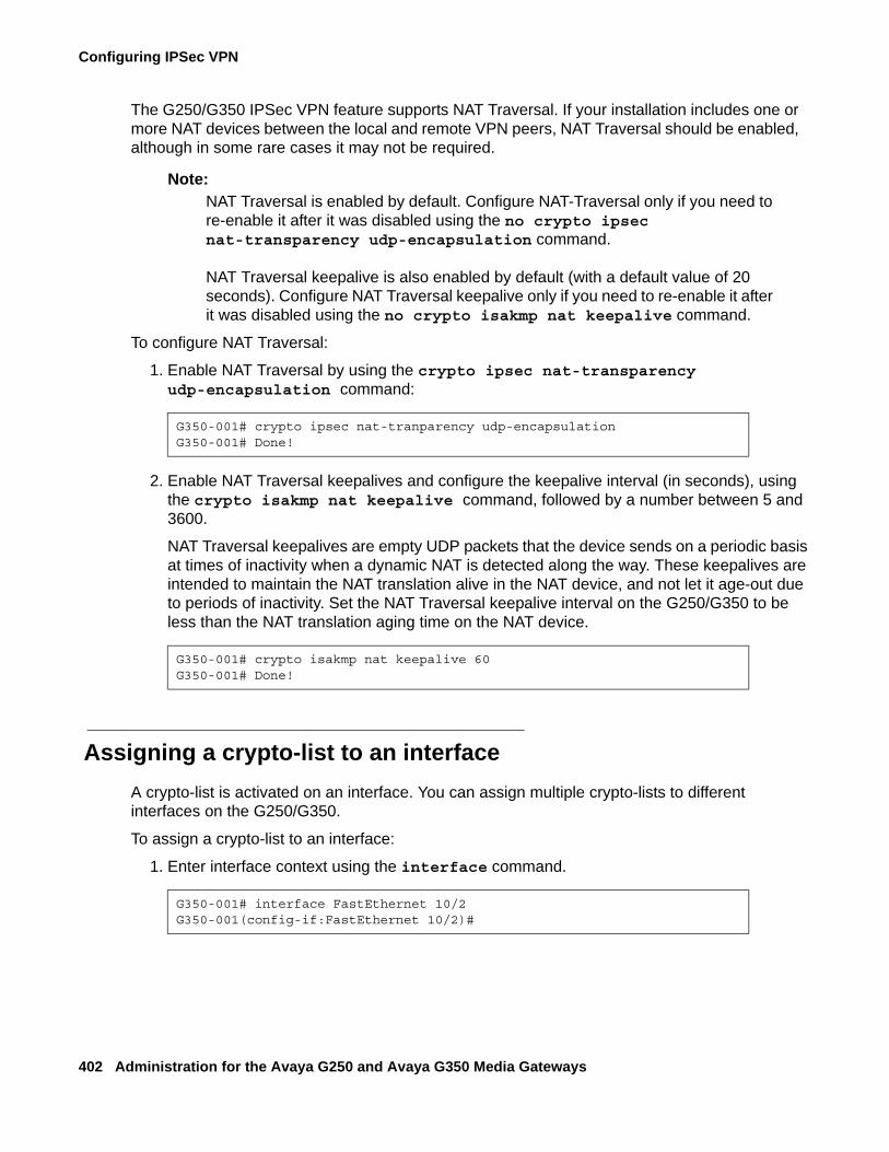
Configuring IPSec VPN
402 Administration for the Avaya G250 and Avaya G350 Media Gateways
The G250/G350 IPSec VPN feature supports NAT Traversal. If your installation includes one or more NAT devices between the local and remote VPN peers, NAT Traversal should be enabled, although in some rare cases it may not be required.
Note:Note: NAT Traversal is enabled by default. Configure NAT-Traversal only if you need to
re-enable it after it was disabled using the no crypto ipsec nat-transparency udp-encapsulation command.
NAT Traversal keepalive is also enabled by default (with a default value of 20 seconds). Configure NAT Traversal keepalive only if you need to re-enable it after it was disabled using the no crypto isakmp nat keepalive command.
To configure NAT Traversal:
1. Enable NAT Traversal by using the crypto ipsec nat-transparency udp-encapsulation command:
2. Enable NAT Traversal keepalives and configure the keepalive interval (in seconds), using the crypto isakmp nat keepalive command, followed by a number between 5 and 3600.
NAT Traversal keepalives are empty UDP packets that the device sends on a periodic basis at times of inactivity when a dynamic NAT is detected along the way. These keepalives are intended to maintain the NAT translation alive in the NAT device, and not let it age-out due to periods of inactivity. Set the NAT Traversal keepalive interval on the G250/G350 to be less than the NAT translation aging time on the NAT device.
Assigning a crypto-list to an interfaceA crypto-list is activated on an interface. You can assign multiple crypto-lists to different interfaces on the G250/G350.
To assign a crypto-list to an interface:
1. Enter interface context using the interface command.
G350-001# crypto ipsec nat-tranparency udp-encapsulationG350-001# Done!
G350-001# crypto isakmp nat keepalive 60G350-001# Done!
G350-001# interface FastEthernet 10/2G350-001(config-if:FastEthernet 10/2)#
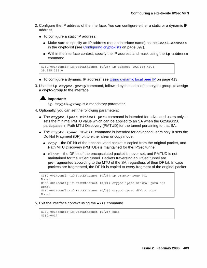
Configuring a site-to-site IPSec VPN
Issue 2 February 2006 403
2. Configure the IP address of the interface. You can configure either a static or a dynamic IP address.
● To configure a static IP address:
● Make sure to specify an IP address (not an interface name) as the local-address in the crypto-list (see Configuring crypto-lists on page 397).
● Within the interface context, specify the IP address and mask using the ip address command.
● To configure a dynamic IP address, see Using dynamic local peer IP on page 413.
3. Use the ip crypto-group command, followed by the index of the crypto-group, to assign a crypto-group to the interface.
! Important:Important: ip crypto-group is a mandatory parameter.
4. Optionally, you can set the following parameters:
● The crypto ipsec minimal pmtu command is intended for advanced users only. It sets the minimal PMTU value which can be applied to an SA when the G250/G350 participates in Path MTU Discovery (PMTUD) for the tunnel pertaining to that SA.
● The crypto ipsec df-bit command is intended for advanced users only. It sets the Do Not Fragment (DF) bit to either clear or copy mode:
● copy – the DF bit of the encapsulated packet is copied from the original packet, and Path MTU Discovery (PMTUD) is maintained for the IPSec tunnel.
● clear – the DF bit of the encapsulated packet is never set, and PMTUD is not maintained for the IPSec tunnel. Packets traversing an IPSec tunnel are pre-fragmented according to the MTU of the SA, regardless of their DF bit. In case packets are fragmented, the DF bit is copied to every fragment of the original packet.
5. Exit the interface context using the exit command.
G350-001(config-if:FastEthernet 10/2)# ip address 192.168.49.1 25.255.255.0
G350-001(config-if:FastEthernet 10/2)# ip crypto-group 901Done!G350-001(config-if:FastEthernet 10/2)# crypto ipsec minimal pmtu 500Done!G350-001(config-if:FastEthernet 10/2)# crypto ipsec df-bit copyDone!
G350-001(config-if:FastEthernet 10/2)# exitG350-001#
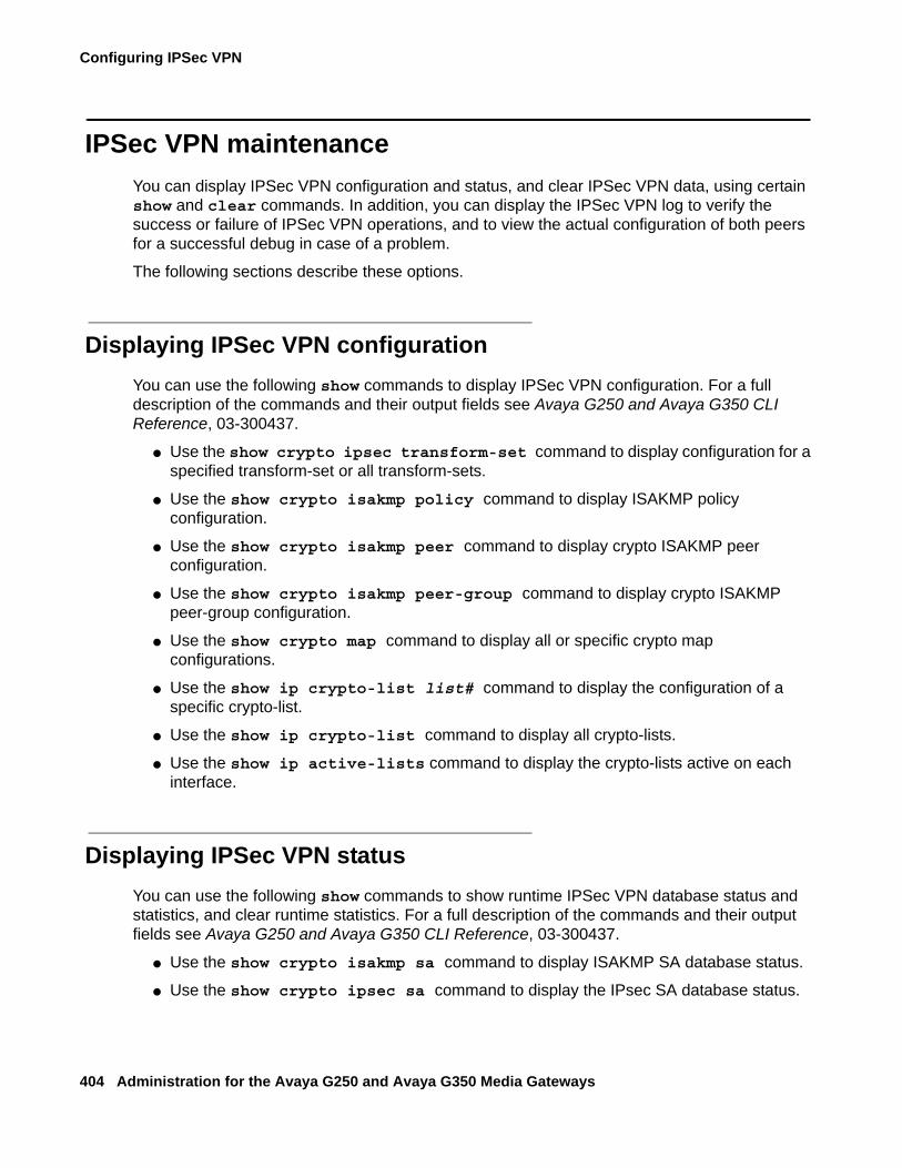
Configuring IPSec VPN
404 Administration for the Avaya G250 and Avaya G350 Media Gateways
IPSec VPN maintenanceYou can display IPSec VPN configuration and status, and clear IPSec VPN data, using certain show and clear commands. In addition, you can display the IPSec VPN log to verify the success or failure of IPSec VPN operations, and to view the actual configuration of both peers for a successful debug in case of a problem.
The following sections describe these options.
Displaying IPSec VPN configurationYou can use the following show commands to display IPSec VPN configuration. For a full description of the commands and their output fields see Avaya G250 and Avaya G350 CLI Reference, 03-300437.
● Use the show crypto ipsec transform-set command to display configuration for a specified transform-set or all transform-sets.
● Use the show crypto isakmp policy command to display ISAKMP policy configuration.
● Use the show crypto isakmp peer command to display crypto ISAKMP peer configuration.
● Use the show crypto isakmp peer-group command to display crypto ISAKMP peer-group configuration.
● Use the show crypto map command to display all or specific crypto map configurations.
● Use the show ip crypto-list list# command to display the configuration of a specific crypto-list.
● Use the show ip crypto-list command to display all crypto-lists.
● Use the show ip active-lists command to display the crypto-lists active on each interface.
Displaying IPSec VPN statusYou can use the following show commands to show runtime IPSec VPN database status and statistics, and clear runtime statistics. For a full description of the commands and their output fields see Avaya G250 and Avaya G350 CLI Reference, 03-300437.
● Use the show crypto isakmp sa command to display ISAKMP SA database status.
● Use the show crypto ipsec sa command to display the IPsec SA database status.
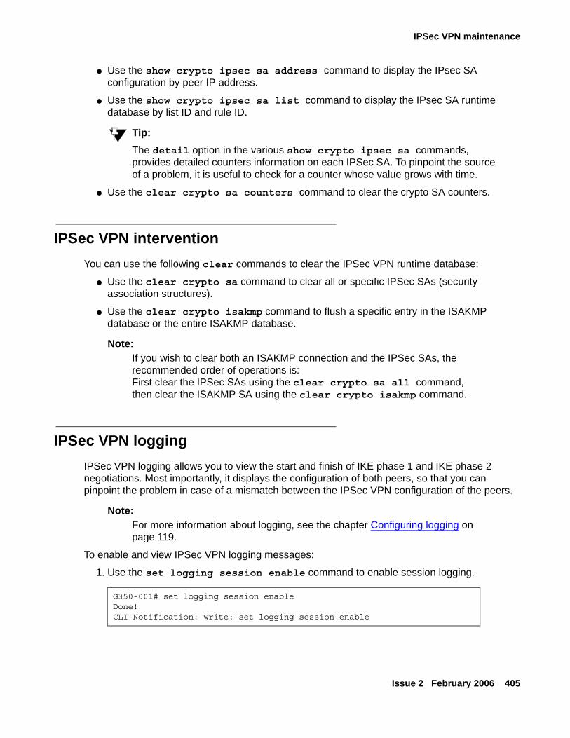
IPSec VPN maintenance
Issue 2 February 2006 405
● Use the show crypto ipsec sa address command to display the IPsec SA configuration by peer IP address.
● Use the show crypto ipsec sa list command to display the IPsec SA runtime database by list ID and rule ID.
Tip:Tip: The detail option in the various show crypto ipsec sa commands,
provides detailed counters information on each IPSec SA. To pinpoint the source of a problem, it is useful to check for a counter whose value grows with time.
● Use the clear crypto sa counters command to clear the crypto SA counters.
IPSec VPN interventionYou can use the following clear commands to clear the IPSec VPN runtime database:
● Use the clear crypto sa command to clear all or specific IPSec SAs (security association structures).
● Use the clear crypto isakmp command to flush a specific entry in the ISAKMP database or the entire ISAKMP database.
Note:Note: If you wish to clear both an ISAKMP connection and the IPSec SAs, the
recommended order of operations is:First clear the IPSec SAs using the clear crypto sa all command, then clear the ISAKMP SA using the clear crypto isakmp command.
IPSec VPN loggingIPSec VPN logging allows you to view the start and finish of IKE phase 1 and IKE phase 2 negotiations. Most importantly, it displays the configuration of both peers, so that you can pinpoint the problem in case of a mismatch between the IPSec VPN configuration of the peers.
Note:Note: For more information about logging, see the chapter Configuring logging on
page 119.
To enable and view IPSec VPN logging messages:
1. Use the set logging session enable command to enable session logging.
G350-001# set logging session enableDone!CLI-Notification: write: set logging session enable
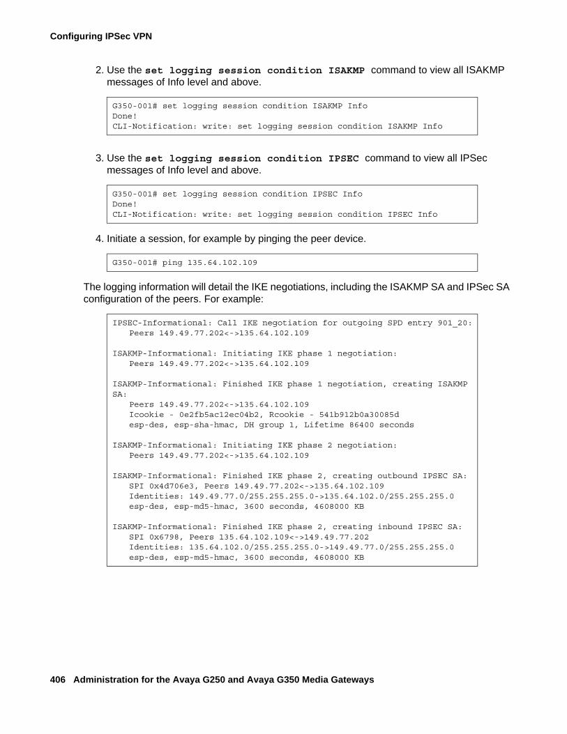
Configuring IPSec VPN
406 Administration for the Avaya G250 and Avaya G350 Media Gateways
2. Use the set logging session condition ISAKMP command to view all ISAKMP messages of Info level and above.
3. Use the set logging session condition IPSEC command to view all IPSec messages of Info level and above.
4. Initiate a session, for example by pinging the peer device.
The logging information will detail the IKE negotiations, including the ISAKMP SA and IPSec SA configuration of the peers. For example:
G350-001# set logging session condition ISAKMP InfoDone!CLI-Notification: write: set logging session condition ISAKMP Info
G350-001# set logging session condition IPSEC InfoDone!CLI-Notification: write: set logging session condition IPSEC Info
G350-001# ping 135.64.102.109
IPSEC-Informational: Call IKE negotiation for outgoing SPD entry 901_20:Peers 149.49.77.202<->135.64.102.109
ISAKMP-Informational: Initiating IKE phase 1 negotiation:Peers 149.49.77.202<->135.64.102.109
ISAKMP-Informational: Finished IKE phase 1 negotiation, creating ISAKMP SA:
Peers 149.49.77.202<->135.64.102.109Icookie - 0e2fb5ac12ec04b2, Rcookie - 541b912b0a30085desp-des, esp-sha-hmac, DH group 1, Lifetime 86400 seconds
ISAKMP-Informational: Initiating IKE phase 2 negotiation:Peers 149.49.77.202<->135.64.102.109
ISAKMP-Informational: Finished IKE phase 2, creating outbound IPSEC SA:SPI 0x4d706e3, Peers 149.49.77.202<->135.64.102.109Identities: 149.49.77.0/255.255.255.0->135.64.102.0/255.255.255.0esp-des, esp-md5-hmac, 3600 seconds, 4608000 KB
ISAKMP-Informational: Finished IKE phase 2, creating inbound IPSEC SA:SPI 0x6798, Peers 135.64.102.109<->149.49.77.202Identities: 135.64.102.0/255.255.255.0->149.49.77.0/255.255.255.0esp-des, esp-md5-hmac, 3600 seconds, 4608000 KB
Typical installations
Issue 2 February 2006 407
Typical installationsThe following sections describe the typical IPSec VPN installations.
● Simple VPN topology — VPN hub and spokes on page 407This includes also an explanation of Using dynamic local peer IP on page 413, and an explanation of Enabling continuous channel on page 416
● Full or partial mesh on page 417
● Full solution — hub-and-spoke with VPN for data and VoIP control backup on page 429
Also included are Typical failover applications:
● Failover using GRE on page 437, using GRE tunneling
● Failover using DNS on page 444
● Failover using a peer-group on page 452
Simple VPN topology — VPN hub and spokesThe simple VPN topology consists of several VPN spokes (branch offices) connected via the Internet to the VPN hub (Main Office).
In this topology:
● The Broadband Internet connection uses cable or DSL modem, with a static public IP address.
● There is a VPN tunnel from each Spoke to the VPN hub over the Internet.
● Only VPN traffic is allowed via the Internet connection.
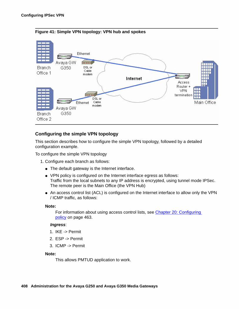
Configuring IPSec VPN
408 Administration for the Avaya G250 and Avaya G350 Media Gateways
Figure 41: Simple VPN topology: VPN hub and spokes
Configuring the simple VPN topologyThis section describes how to configure the simple VPN topology, followed by a detailed configuration example.
To configure the simple VPN topology
1. Configure each branch as follows:● The default gateway is the Internet interface.● VPN policy is configured on the Internet interface egress as follows:
Traffic from the local subnets to any IP address is encrypted, using tunnel mode IPSec. The remote peer is the Main Office (the VPN Hub)
● An access control list (ACL) is configured on the Internet interface to allow only the VPN / ICMP traffic, as follows:
Note:Note: For information about using access control lists, see Chapter 20: Configuring
policy on page 463.
Ingress:1. IKE -> Permit2. ESP -> Permit3. ICMP -> Permit
Note:Note: This allows PMTUD application to work.
Typical installations
Issue 2 February 2006 409
4. All allowed services from any IP address to any local subnet -> Permit
Note:Note: Due to the definition of the VPN Policy, this will be allowed only if traffic comes
over ESP.5. Default VPN policy-> DenyEgress:1. IKE -> Permit2. ESP -> Permit3. ICMP -> Permit
Note:Note: This allows the PMTUD application to work.
4. All allowed services from any local subnet to any IP address -> Permit
Note:Note: This traffic is tunnelled using VPN.
5. Default -> Deny
2. Configure the VPN Hub (Main Office) as follows:
● Static routing: Branch subnets -> Internet interface.● The VPN policy portion for the branch is configured as a mirror image of the branch, as
follows:Traffic from any to branch local subnets -> encrypt, using tunnel mode IPSec. The remote peer is the VPN Spoke (Branch Internet address).
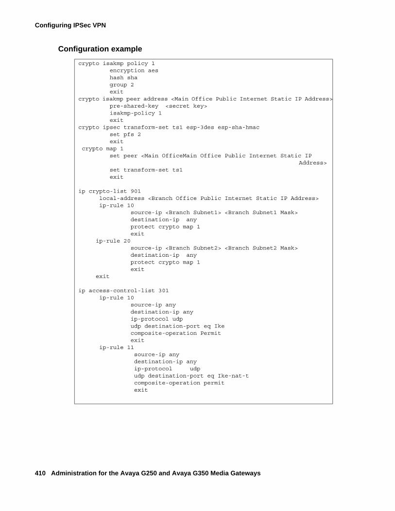
Configuring IPSec VPN
410 Administration for the Avaya G250 and Avaya G350 Media Gateways
Configuration example
crypto isakmp policy 1 encryption aes hash sha group 2 exitcrypto isakmp peer address <Main Office Public Internet Static IP Address> pre-shared-key <secret key> isakmp-policy 1 exit crypto ipsec transform-set ts1 esp-3des esp-sha-hmac set pfs 2 exit crypto map 1 set peer <Main OfficeMain Office Public Internet Static IP
Address> set transform-set ts1 exit ip crypto-list 901 local-address <Branch Office Public Internet Static IP Address> ip-rule 10 source-ip <Branch Subnet1> <Branch Subnet1 Mask> destination-ip any protect crypto map 1 exit ip-rule 20 source-ip <Branch Subnet2> <Branch Subnet2 Mask> destination-ip any protect crypto map 1 exit
exit
ip access-control-list 301 ip-rule 10 source-ip any destination-ip any ip-protocol udp udp destination-port eq Ike composite-operation Permit exit ip-rule 11 source-ip any destination-ip any ip-protocol udp udp destination-port eq Ike-nat-t composite-operation permit exit
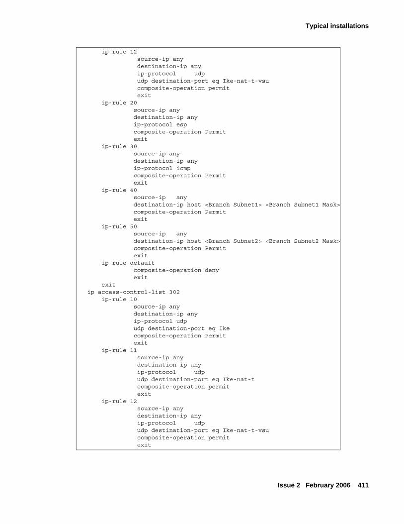
Typical installations
Issue 2 February 2006 411
ip-rule 12 source-ip any destination-ip any ip-protocol udp udp destination-port eq Ike-nat-t-vsu composite-operation permit exit ip-rule 20 source-ip any destination-ip any ip-protocol esp composite-operation Permit exit ip-rule 30 source-ip any destination-ip any ip-protocol icmp composite-operation Permit exit ip-rule 40 source-ip any destination-ip host <Branch Subnet1> <Branch Subnet1 Mask> composite-operation Permit exit ip-rule 50 source-ip any destination-ip host <Branch Subnet2> <Branch Subnet2 Mask> composite-operation Permit exit ip-rule default composite-operation deny exit exit ip access-control-list 302 ip-rule 10 source-ip any destination-ip any ip-protocol udp udp destination-port eq Ike composite-operation Permit exit ip-rule 11 source-ip any destination-ip any ip-protocol udp udp destination-port eq Ike-nat-t composite-operation permit exit ip-rule 12 source-ip any destination-ip any ip-protocol udp udp destination-port eq Ike-nat-t-vsu composite-operation permit exit
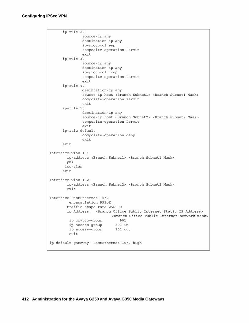
Configuring IPSec VPN
412 Administration for the Avaya G250 and Avaya G350 Media Gateways
ip-rule 20 source-ip any destination-ip any ip-protocol esp composite-operation Permit exit ip-rule 30 source-ip any destination-ip any ip-protocol icmp composite-operation Permit exit ip-rule 40 desintation-ip any source-ip host <Branch Subnet1> <Branch Subnet1 Mask> composite-operation Permit exit ip-rule 50 destination-ip any source-ip host <Branch Subnet2> <Branch Subnet2 Mask> composite-operation Permit exit ip-rule default composite-operation deny exit exit
Interface vlan 1.1 ip-address <Branch Subnet1> <Branch Subnet1 Mask> pmi icc-vlan exit
Interface vlan 1.2 ip-address <Branch Subnet2> <Branch Subnet2 Mask> exit
Interface FastEthernet 10/2 encapsulation PPPoE traffic-shape rate 256000 ip Address <Branch Office Public Internet Static IP Address>
<Branch Office Public Internet network mask> ip crypto-group 901 ip access-group 301 in ip access-group 302 out exit
ip default-gateway FastEthernet 10/2 high
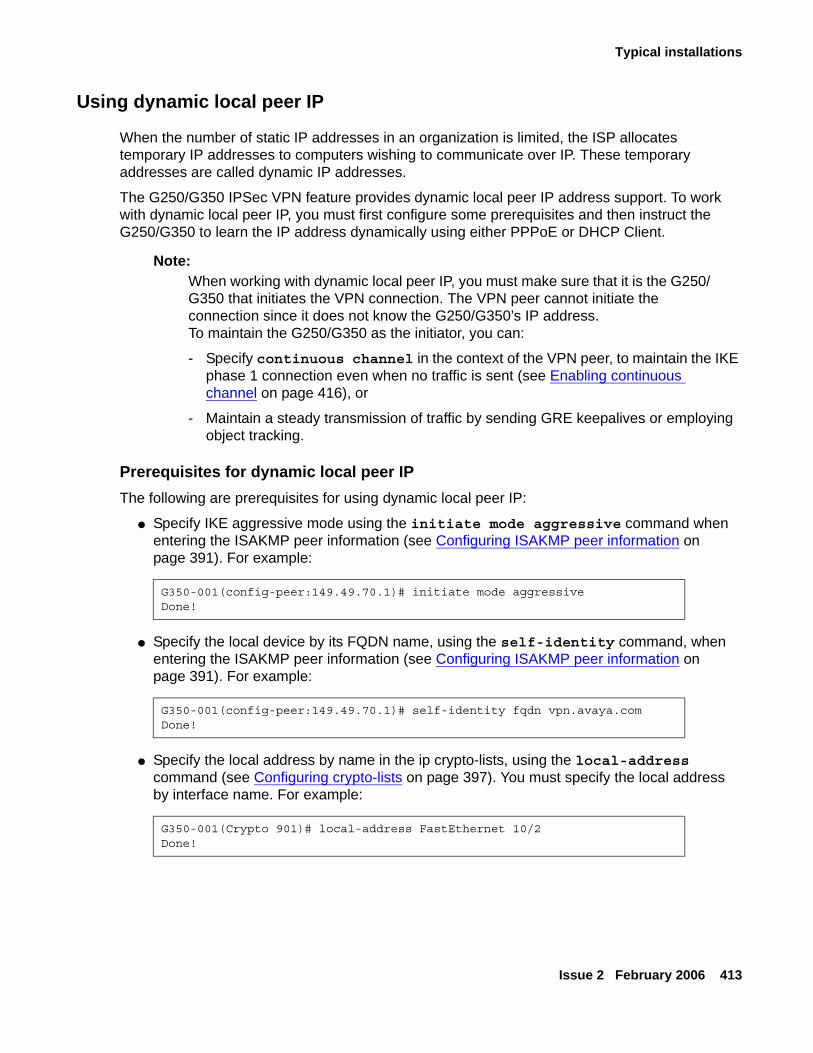
Typical installations
Issue 2 February 2006 413
Using dynamic local peer IP
When the number of static IP addresses in an organization is limited, the ISP allocates temporary IP addresses to computers wishing to communicate over IP. These temporary addresses are called dynamic IP addresses.
The G250/G350 IPSec VPN feature provides dynamic local peer IP address support. To work with dynamic local peer IP, you must first configure some prerequisites and then instruct the G250/G350 to learn the IP address dynamically using either PPPoE or DHCP Client.
Note:Note: When working with dynamic local peer IP, you must make sure that it is the G250/
G350 that initiates the VPN connection. The VPN peer cannot initiate the connection since it does not know the G250/G350’s IP address. To maintain the G250/G350 as the initiator, you can:
- Specify continuous channel in the context of the VPN peer, to maintain the IKE phase 1 connection even when no traffic is sent (see Enabling continuous channel on page 416), or
- Maintain a steady transmission of traffic by sending GRE keepalives or employing object tracking.
Prerequisites for dynamic local peer IPThe following are prerequisites for using dynamic local peer IP:
● Specify IKE aggressive mode using the initiate mode aggressive command when entering the ISAKMP peer information (see Configuring ISAKMP peer information on page 391). For example:
● Specify the local device by its FQDN name, using the self-identity command, when entering the ISAKMP peer information (see Configuring ISAKMP peer information on page 391). For example:
● Specify the local address by name in the ip crypto-lists, using the local-address command (see Configuring crypto-lists on page 397). You must specify the local address by interface name. For example:
G350-001(config-peer:149.49.70.1)# initiate mode aggressiveDone!
G350-001(config-peer:149.49.70.1)# self-identity fqdn vpn.avaya.comDone!
G350-001(Crypto 901)# local-address FastEthernet 10/2Done!
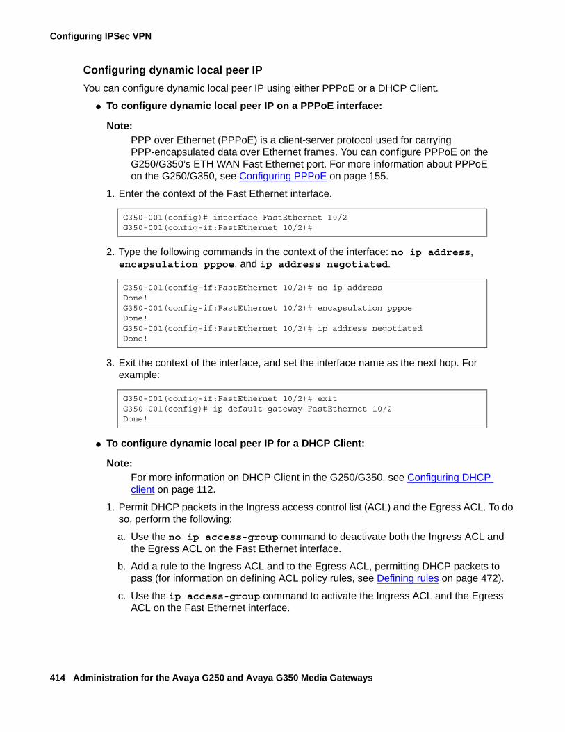
Configuring IPSec VPN
414 Administration for the Avaya G250 and Avaya G350 Media Gateways
Configuring dynamic local peer IPYou can configure dynamic local peer IP using either PPPoE or a DHCP Client.
● To configure dynamic local peer IP on a PPPoE interface:
Note:Note: PPP over Ethernet (PPPoE) is a client-server protocol used for carrying
PPP-encapsulated data over Ethernet frames. You can configure PPPoE on the G250/G350’s ETH WAN Fast Ethernet port. For more information about PPPoE on the G250/G350, see Configuring PPPoE on page 155.
1. Enter the context of the Fast Ethernet interface.
2. Type the following commands in the context of the interface: no ip address, encapsulation pppoe, and ip address negotiated.
3. Exit the context of the interface, and set the interface name as the next hop. For example:
● To configure dynamic local peer IP for a DHCP Client:
Note:Note: For more information on DHCP Client in the G250/G350, see Configuring DHCP
client on page 112.
1. Permit DHCP packets in the Ingress access control list (ACL) and the Egress ACL. To do so, perform the following:
a. Use the no ip access-group command to deactivate both the Ingress ACL and the Egress ACL on the Fast Ethernet interface.
b. Add a rule to the Ingress ACL and to the Egress ACL, permitting DHCP packets to pass (for information on defining ACL policy rules, see Defining rules on page 472).
c. Use the ip access-group command to activate the Ingress ACL and the Egress ACL on the Fast Ethernet interface.
G350-001(config)# interface FastEthernet 10/2G350-001(config-if:FastEthernet 10/2)#
G350-001(config-if:FastEthernet 10/2)# no ip addressDone!G350-001(config-if:FastEthernet 10/2)# encapsulation pppoeDone!G350-001(config-if:FastEthernet 10/2)# ip address negotiatedDone!
G350-001(config-if:FastEthernet 10/2)# exitG350-001(config)# ip default-gateway FastEthernet 10/2Done!
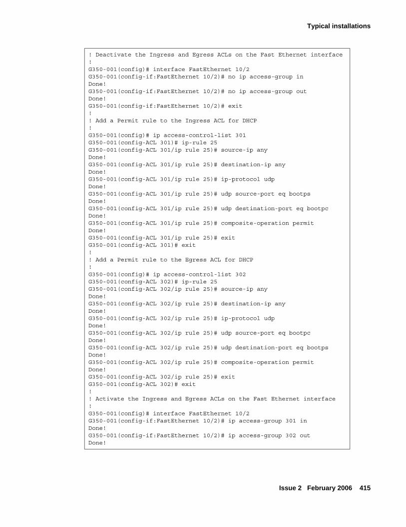
Typical installations
Issue 2 February 2006 415
! Deactivate the Ingress and Egress ACLs on the Fast Ethernet interface!G350-001(config)# interface FastEthernet 10/2G350-001(config-if:FastEthernet 10/2)# no ip access-group inDone!G350-001(config-if:FastEthernet 10/2)# no ip access-group outDone!G350-001(config-if:FastEthernet 10/2)# exit!! Add a Permit rule to the Ingress ACL for DHCP!G350-001(config)# ip access-control-list 301G350-001(config-ACL 301)# ip-rule 25G350-001(config-ACL 301/ip rule 25)# source-ip anyDone!G350-001(config-ACL 301/ip rule 25)# destination-ip anyDone!G350-001(config-ACL 301/ip rule 25)# ip-protocol udpDone!G350-001(config-ACL 301/ip rule 25)# udp source-port eq bootpsDone!G350-001(config-ACL 301/ip rule 25)# udp destination-port eq bootpcDone!G350-001(config-ACL 301/ip rule 25)# composite-operation permitDone!G350-001(config-ACL 301/ip rule 25)# exitG350-001(config-ACL 301)# exit!! Add a Permit rule to the Egress ACL for DHCP!G350-001(config)# ip access-control-list 302G350-001(config-ACL 302)# ip-rule 25G350-001(config-ACL 302/ip rule 25)# source-ip anyDone!G350-001(config-ACL 302/ip rule 25)# destination-ip anyDone!G350-001(config-ACL 302/ip rule 25)# ip-protocol udpDone!G350-001(config-ACL 302/ip rule 25)# udp source-port eq bootpcDone!G350-001(config-ACL 302/ip rule 25)# udp destination-port eq bootpsDone!G350-001(config-ACL 302/ip rule 25)# composite-operation permitDone!G350-001(config-ACL 302/ip rule 25)# exitG350-001(config-ACL 302)# exit!! Activate the Ingress and Egress ACLs on the Fast Ethernet interface!G350-001(config)# interface FastEthernet 10/2G350-001(config-if:FastEthernet 10/2)# ip access-group 301 inDone!G350-001(config-if:FastEthernet 10/2)# ip access-group 302 outDone!
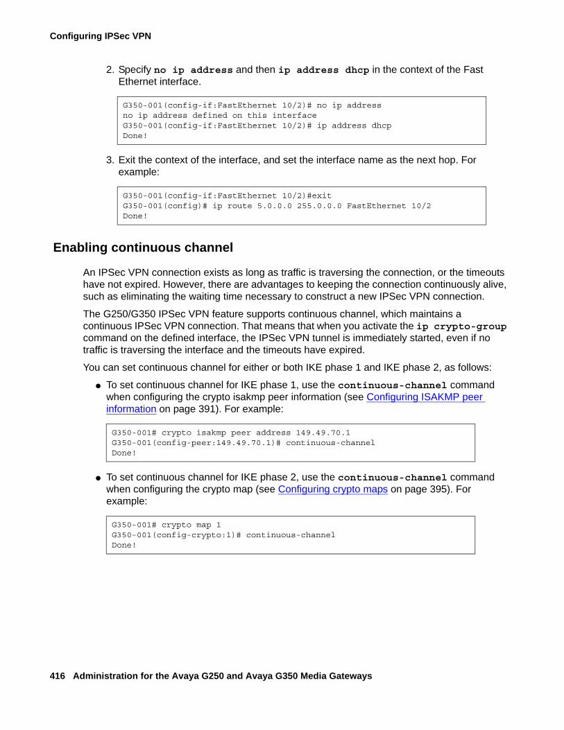
Configuring IPSec VPN
416 Administration for the Avaya G250 and Avaya G350 Media Gateways
2. Specify no ip address and then ip address dhcp in the context of the Fast Ethernet interface.
3. Exit the context of the interface, and set the interface name as the next hop. For example:
Enabling continuous channel
An IPSec VPN connection exists as long as traffic is traversing the connection, or the timeouts have not expired. However, there are advantages to keeping the connection continuously alive, such as eliminating the waiting time necessary to construct a new IPSec VPN connection.
The G250/G350 IPSec VPN feature supports continuous channel, which maintains a continuous IPSec VPN connection. That means that when you activate the ip crypto-group command on the defined interface, the IPSec VPN tunnel is immediately started, even if no traffic is traversing the interface and the timeouts have expired.
You can set continuous channel for either or both IKE phase 1 and IKE phase 2, as follows:
● To set continuous channel for IKE phase 1, use the continuous-channel command when configuring the crypto isakmp peer information (see Configuring ISAKMP peer information on page 391). For example:
● To set continuous channel for IKE phase 2, use the continuous-channel command when configuring the crypto map (see Configuring crypto maps on page 395). For example:
G350-001(config-if:FastEthernet 10/2)# no ip addressno ip address defined on this interfaceG350-001(config-if:FastEthernet 10/2)# ip address dhcpDone!
G350-001(config-if:FastEthernet 10/2)#exitG350-001(config)# ip route 5.0.0.0 255.0.0.0 FastEthernet 10/2Done!
G350-001# crypto isakmp peer address 149.49.70.1G350-001(config-peer:149.49.70.1)# continuous-channelDone!
G350-001# crypto map 1G350-001(config-crypto:1)# continuous-channelDone!
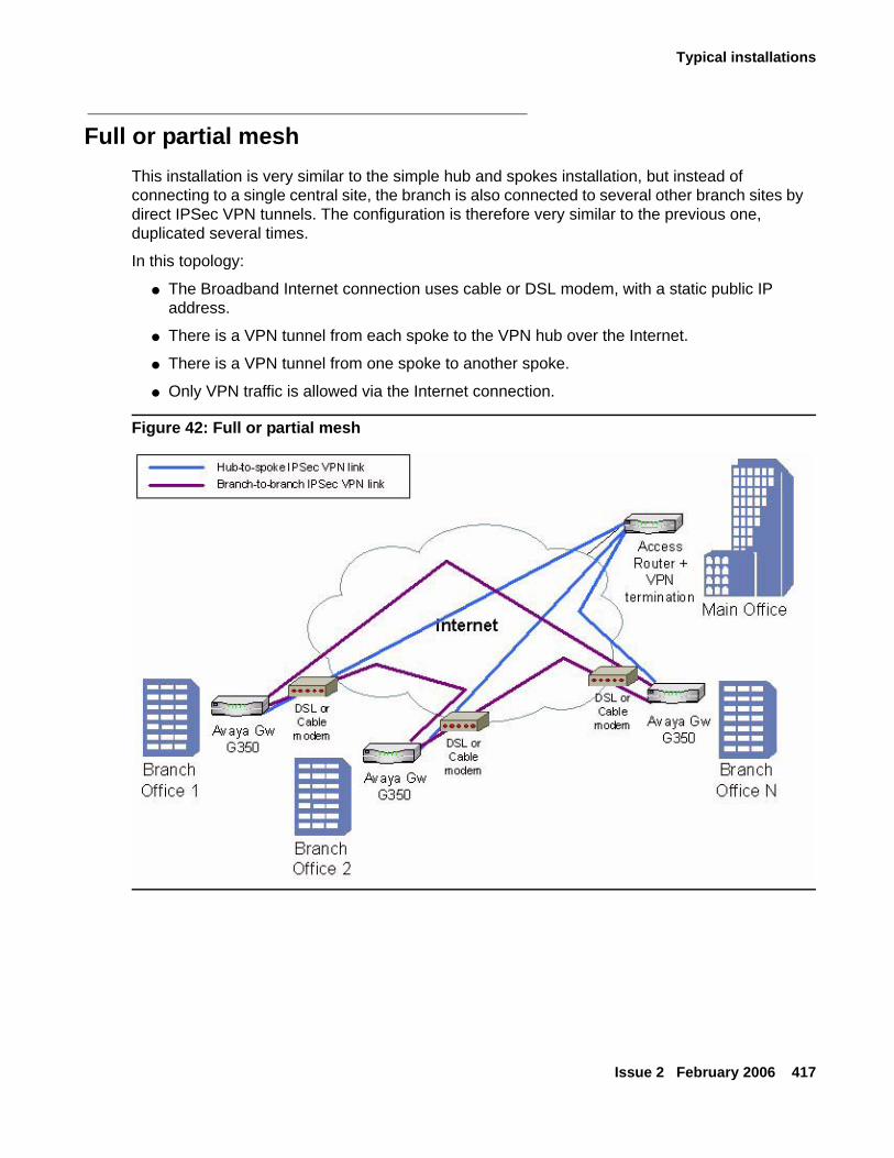
Typical installations
Issue 2 February 2006 417
Full or partial meshThis installation is very similar to the simple hub and spokes installation, but instead of connecting to a single central site, the branch is also connected to several other branch sites by direct IPSec VPN tunnels. The configuration is therefore very similar to the previous one, duplicated several times.
In this topology:
● The Broadband Internet connection uses cable or DSL modem, with a static public IP address.
● There is a VPN tunnel from each spoke to the VPN hub over the Internet.
● There is a VPN tunnel from one spoke to another spoke.
● Only VPN traffic is allowed via the Internet connection.
Figure 42: Full or partial mesh
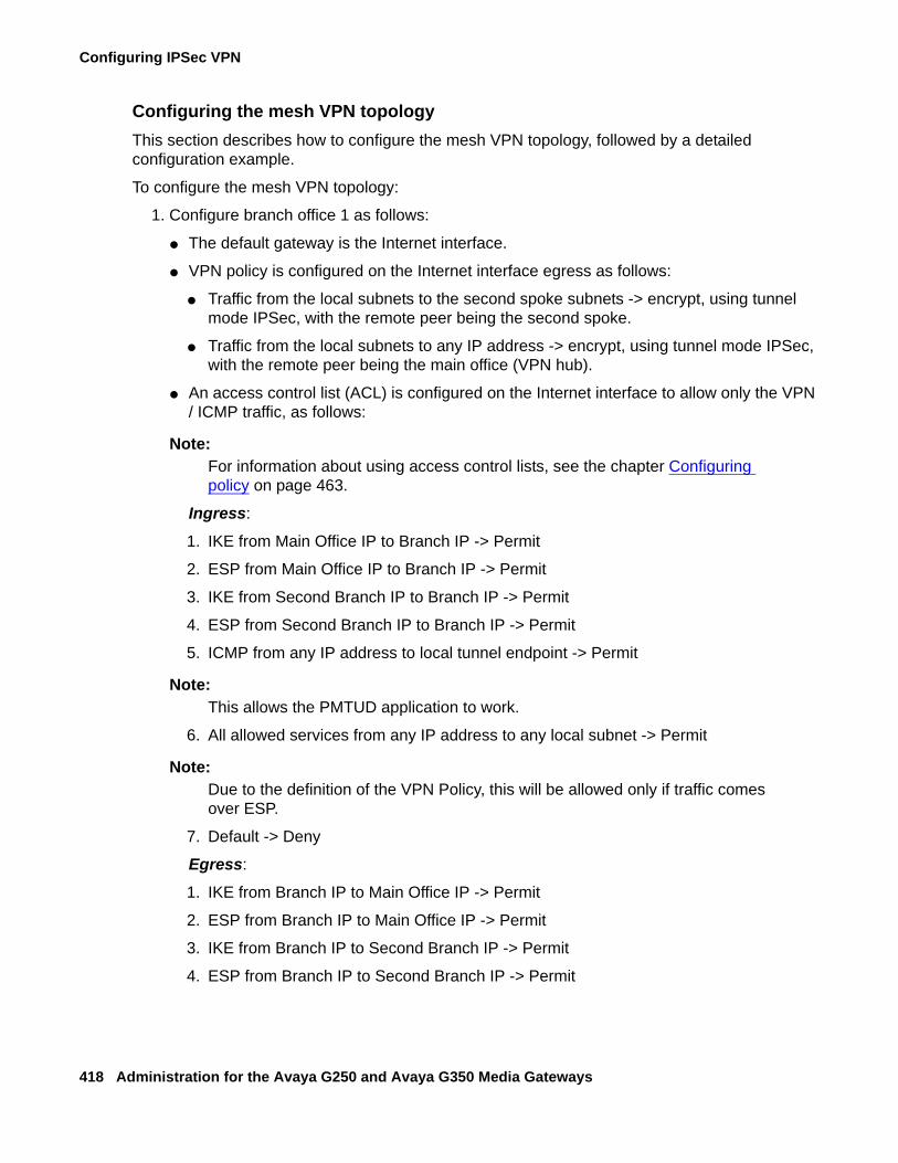
Configuring IPSec VPN
418 Administration for the Avaya G250 and Avaya G350 Media Gateways
Configuring the mesh VPN topologyThis section describes how to configure the mesh VPN topology, followed by a detailed configuration example.
To configure the mesh VPN topology:
1. Configure branch office 1 as follows:
● The default gateway is the Internet interface.
● VPN policy is configured on the Internet interface egress as follows:
● Traffic from the local subnets to the second spoke subnets -> encrypt, using tunnel mode IPSec, with the remote peer being the second spoke.
● Traffic from the local subnets to any IP address -> encrypt, using tunnel mode IPSec,with the remote peer being the main office (VPN hub).
● An access control list (ACL) is configured on the Internet interface to allow only the VPN / ICMP traffic, as follows:
Note:Note: For information about using access control lists, see the chapter Configuring
policy on page 463.
Ingress:
1. IKE from Main Office IP to Branch IP -> Permit
2. ESP from Main Office IP to Branch IP -> Permit
3. IKE from Second Branch IP to Branch IP -> Permit
4. ESP from Second Branch IP to Branch IP -> Permit
5. ICMP from any IP address to local tunnel endpoint -> Permit
Note:Note: This allows the PMTUD application to work.
6. All allowed services from any IP address to any local subnet -> Permit
Note:Note: Due to the definition of the VPN Policy, this will be allowed only if traffic comes
over ESP.
7. Default -> Deny
Egress:
1. IKE from Branch IP to Main Office IP -> Permit
2. ESP from Branch IP to Main Office IP -> Permit
3. IKE from Branch IP to Second Branch IP -> Permit
4. ESP from Branch IP to Second Branch IP -> Permit
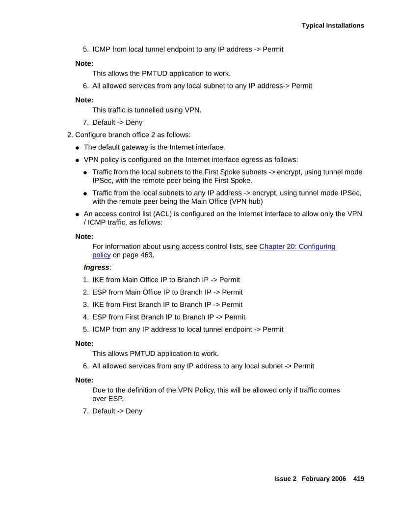
Typical installations
Issue 2 February 2006 419
5. ICMP from local tunnel endpoint to any IP address -> Permit
Note:Note: This allows the PMTUD application to work.
6. All allowed services from any local subnet to any IP address-> Permit
Note:Note: This traffic is tunnelled using VPN.
7. Default -> Deny
2. Configure branch office 2 as follows:
● The default gateway is the Internet interface.
● VPN policy is configured on the Internet interface egress as follows:
● Traffic from the local subnets to the First Spoke subnets -> encrypt, using tunnel mode IPSec, with the remote peer being the First Spoke.
● Traffic from the local subnets to any IP address -> encrypt, using tunnel mode IPSec,with the remote peer being the Main Office (VPN hub)
● An access control list (ACL) is configured on the Internet interface to allow only the VPN / ICMP traffic, as follows:
Note:Note: For information about using access control lists, see Chapter 20: Configuring
policy on page 463.
Ingress:
1. IKE from Main Office IP to Branch IP -> Permit
2. ESP from Main Office IP to Branch IP -> Permit
3. IKE from First Branch IP to Branch IP -> Permit
4. ESP from First Branch IP to Branch IP -> Permit
5. ICMP from any IP address to local tunnel endpoint -> Permit
Note:Note: This allows PMTUD application to work.
6. All allowed services from any IP address to any local subnet -> Permit
Note:Note: Due to the definition of the VPN Policy, this will be allowed only if traffic comes
over ESP.
7. Default -> Deny
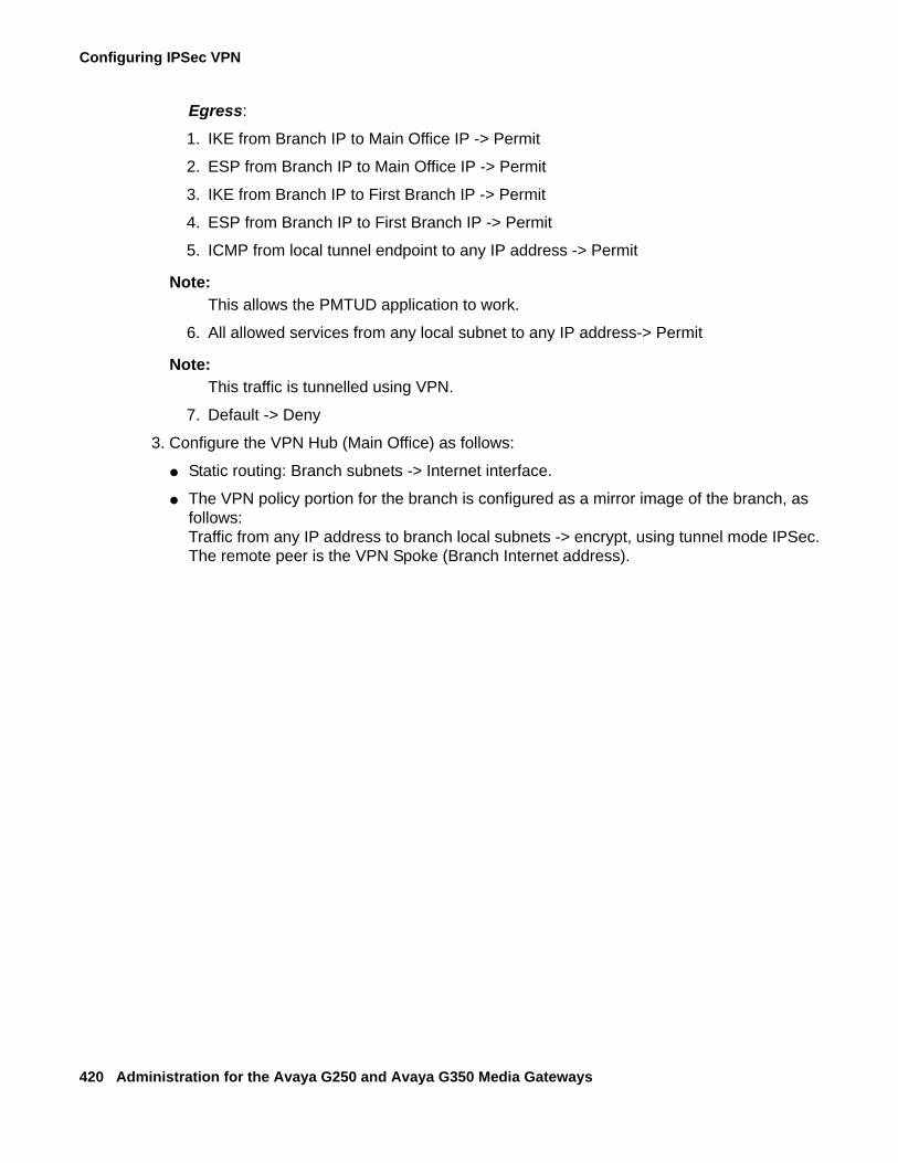
Configuring IPSec VPN
420 Administration for the Avaya G250 and Avaya G350 Media Gateways
Egress:
1. IKE from Branch IP to Main Office IP -> Permit
2. ESP from Branch IP to Main Office IP -> Permit
3. IKE from Branch IP to First Branch IP -> Permit
4. ESP from Branch IP to First Branch IP -> Permit
5. ICMP from local tunnel endpoint to any IP address -> Permit
Note:Note: This allows the PMTUD application to work.
6. All allowed services from any local subnet to any IP address-> Permit
Note:Note: This traffic is tunnelled using VPN.
7. Default -> Deny
3. Configure the VPN Hub (Main Office) as follows:
● Static routing: Branch subnets -> Internet interface.
● The VPN policy portion for the branch is configured as a mirror image of the branch, as follows:Traffic from any IP address to branch local subnets -> encrypt, using tunnel mode IPSec.The remote peer is the VPN Spoke (Branch Internet address).
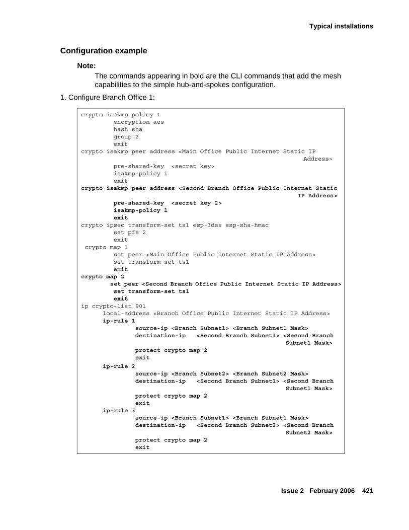
Typical installations
Issue 2 February 2006 421
Configuration example
Note:Note: The commands appearing in bold are the CLI commands that add the mesh
capabilities to the simple hub-and-spokes configuration.
1. Configure Branch Office 1:
crypto isakmp policy 1 encryption aes hash sha group 2 exitcrypto isakmp peer address <Main Office Public Internet Static IP
Address> pre-shared-key <secret key> isakmp-policy 1 exit crypto isakmp peer address <Second Branch Office Public Internet Static
IP Address> pre-shared-key <secret key 2> isakmp-policy 1 exit crypto ipsec transform-set ts1 esp-3des esp-sha-hmac set pfs 2 exit crypto map 1 set peer <Main Office Public Internet Static IP Address> set transform-set ts1 exitcrypto map 2 set peer <Second Branch Office Public Internet Static IP Address> set transform-set ts1 exitip crypto-list 901 local-address <Branch Office Public Internet Static IP Address> ip-rule 1 source-ip <Branch Subnet1> <Branch Subnet1 Mask> destination-ip <Second Branch Subnet1> <Second Branch
Subnet1 Mask> protect crypto map 2 exit
ip-rule 2 source-ip <Branch Subnet2> <Branch Subnet2 Mask> destination-ip <Second Branch Subnet1> <Second Branch
Subnet1 Mask> protect crypto map 2 exit ip-rule 3 source-ip <Branch Subnet1> <Branch Subnet1 Mask> destination-ip <Second Branch Subnet2> <Second Branch
Subnet2 Mask> protect crypto map 2 exit
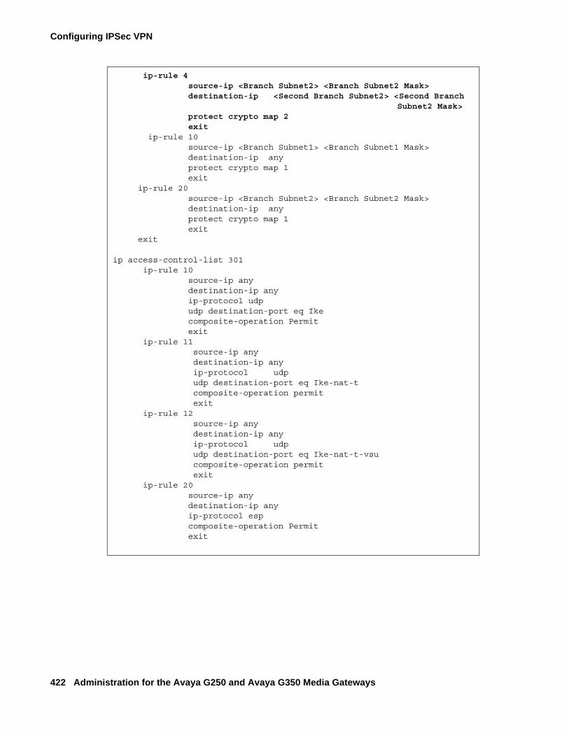
Configuring IPSec VPN
422 Administration for the Avaya G250 and Avaya G350 Media Gateways
ip-rule 4 source-ip <Branch Subnet2> <Branch Subnet2 Mask> destination-ip <Second Branch Subnet2> <Second Branch
Subnet2 Mask> protect crypto map 2 exit ip-rule 10 source-ip <Branch Subnet1> <Branch Subnet1 Mask> destination-ip any protect crypto map 1 exit ip-rule 20 source-ip <Branch Subnet2> <Branch Subnet2 Mask> destination-ip any protect crypto map 1 exit
exit
ip access-control-list 301 ip-rule 10 source-ip any destination-ip any ip-protocol udp udp destination-port eq Ike composite-operation Permit exit ip-rule 11 source-ip any destination-ip any ip-protocol udp udp destination-port eq Ike-nat-t composite-operation permit exit ip-rule 12 source-ip any destination-ip any ip-protocol udp udp destination-port eq Ike-nat-t-vsu composite-operation permit exit ip-rule 20 source-ip any destination-ip any ip-protocol esp composite-operation Permit exit

Typical installations
Issue 2 February 2006 423
ip-rule 30 source-ip any
destination-ip any ip-protocol icmp composite-operation Permit exit ip-rule 40 source-ip any destination-ip host <Branch Subnet1> <Branch Subnet1 Mask> composite-operation Permit exit ip-rule 50 source-ip any destination-ip host <Branch Subnet2> <Branch Subnet2 Mask> composite-operation Permit exit ip-rule default composite-operation deny exit exit
ip access-control-list 302 ip-rule 10 source-ip any destination-ip any ip-protocol udp udp destination-port eq Ike composite-operation Permit exit ip-rule 11 source-ip any destination-ip any ip-protocol udp udp destination-port eq Ike-nat-t composite-operation permit exit ip-rule 12 source-ip any destination-ip any ip-protocol udp udp destination-port eq Ike-nat-t-vsu composite-operation permit exit ip-rule 20 source-ip any destination-ip any ip-protocol esp composite-operation Permit exit
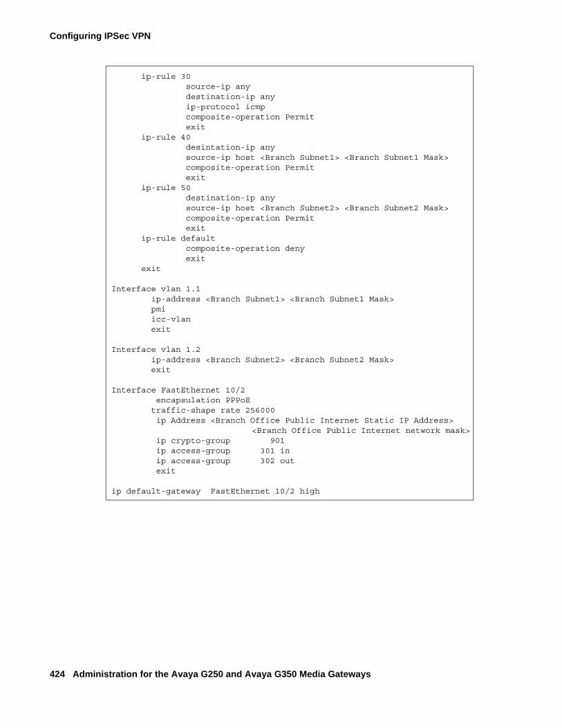
Configuring IPSec VPN
424 Administration for the Avaya G250 and Avaya G350 Media Gateways
ip-rule 30 source-ip any destination-ip any ip-protocol icmp composite-operation Permit exit ip-rule 40 desintation-ip any source-ip host <Branch Subnet1> <Branch Subnet1 Mask> composite-operation Permit exit ip-rule 50 destination-ip any source-ip host <Branch Subnet2> <Branch Subnet2 Mask> composite-operation Permit exit ip-rule default composite-operation deny exit exit
Interface vlan 1.1 ip-address <Branch Subnet1> <Branch Subnet1 Mask> pmi icc-vlan exit
Interface vlan 1.2 ip-address <Branch Subnet2> <Branch Subnet2 Mask> exit
Interface FastEthernet 10/2 encapsulation PPPoE traffic-shape rate 256000 ip Address <Branch Office Public Internet Static IP Address>
<Branch Office Public Internet network mask> ip crypto-group 901 ip access-group 301 in ip access-group 302 out exit
ip default-gateway FastEthernet 10/2 high
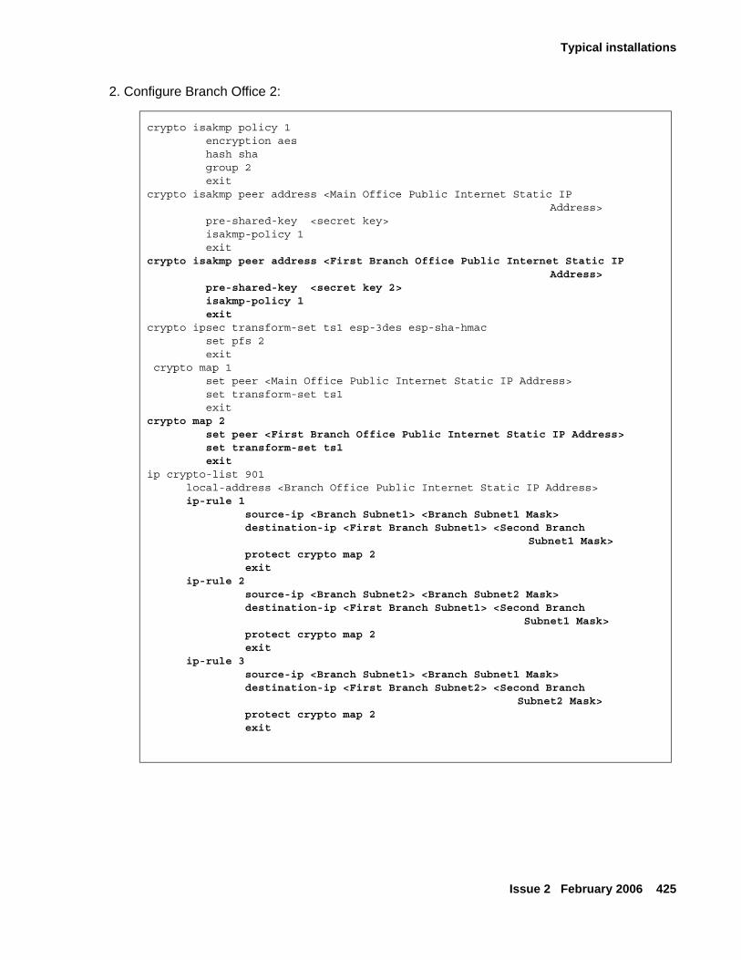
Typical installations
Issue 2 February 2006 425
2. Configure Branch Office 2:
crypto isakmp policy 1 encryption aes hash sha group 2 exitcrypto isakmp peer address <Main Office Public Internet Static IP
Address> pre-shared-key <secret key> isakmp-policy 1 exit crypto isakmp peer address <First Branch Office Public Internet Static IP
Address> pre-shared-key <secret key 2> isakmp-policy 1 exit crypto ipsec transform-set ts1 esp-3des esp-sha-hmac set pfs 2 exit crypto map 1 set peer <Main Office Public Internet Static IP Address> set transform-set ts1 exitcrypto map 2 set peer <First Branch Office Public Internet Static IP Address> set transform-set ts1 exitip crypto-list 901 local-address <Branch Office Public Internet Static IP Address> ip-rule 1 source-ip <Branch Subnet1> <Branch Subnet1 Mask> destination-ip <First Branch Subnet1> <Second Branch
Subnet1 Mask> protect crypto map 2 exit ip-rule 2 source-ip <Branch Subnet2> <Branch Subnet2 Mask> destination-ip <First Branch Subnet1> <Second Branch
Subnet1 Mask> protect crypto map 2 exit ip-rule 3 source-ip <Branch Subnet1> <Branch Subnet1 Mask> destination-ip <First Branch Subnet2> <Second Branch
Subnet2 Mask> protect crypto map 2 exit
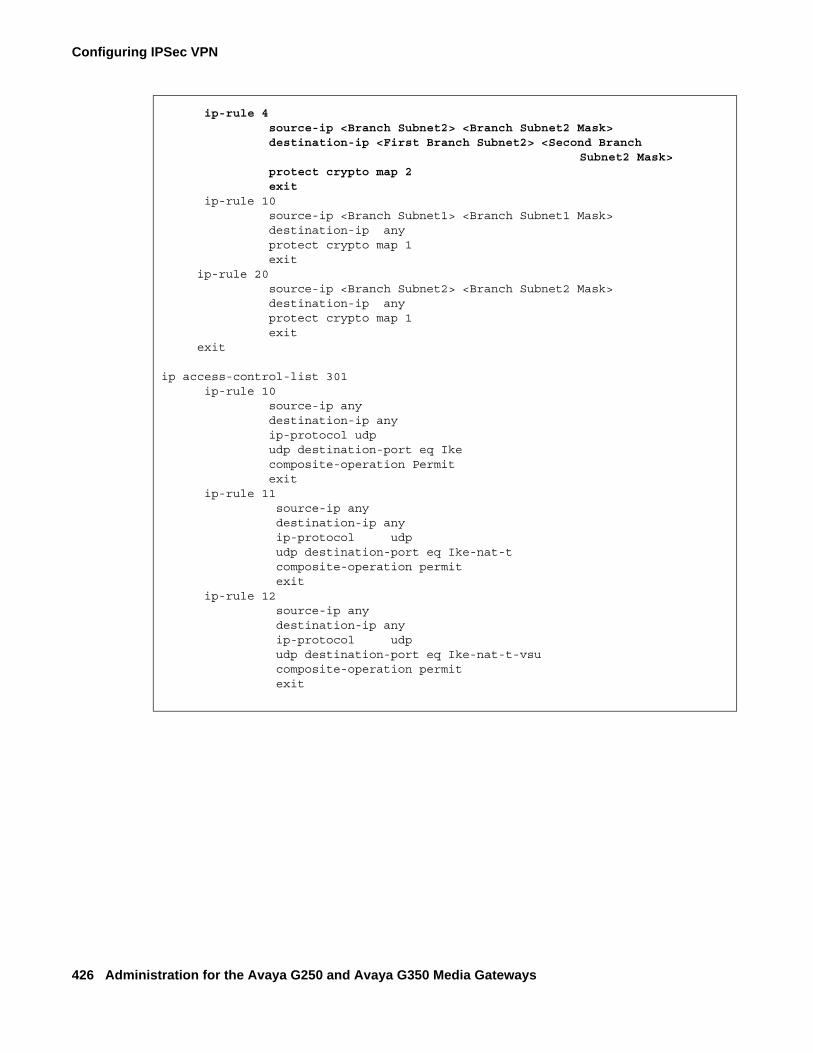
Configuring IPSec VPN
426 Administration for the Avaya G250 and Avaya G350 Media Gateways
ip-rule 4 source-ip <Branch Subnet2> <Branch Subnet2 Mask> destination-ip <First Branch Subnet2> <Second Branch
Subnet2 Mask> protect crypto map 2 exit ip-rule 10 source-ip <Branch Subnet1> <Branch Subnet1 Mask> destination-ip any protect crypto map 1 exit ip-rule 20 source-ip <Branch Subnet2> <Branch Subnet2 Mask> destination-ip any protect crypto map 1 exit
exit
ip access-control-list 301 ip-rule 10 source-ip any destination-ip any ip-protocol udp udp destination-port eq Ike composite-operation Permit exit ip-rule 11 source-ip any destination-ip any ip-protocol udp udp destination-port eq Ike-nat-t composite-operation permit exit ip-rule 12 source-ip any destination-ip any ip-protocol udp udp destination-port eq Ike-nat-t-vsu composite-operation permit exit
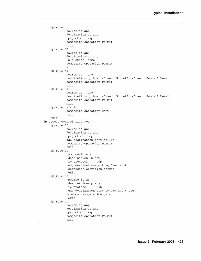
Typical installations
Issue 2 February 2006 427
ip-rule 20 source-ip any destination-ip any ip-protocol esp composite-operation Permit exit ip-rule 30 source-ip any destination-ip any ip-protocol icmp composite-operation Permit exit ip-rule 40 source-ip any destination-ip host <Branch Subnet1> <Branch Subnet1 Mask> composite-operation Permit exit ip-rule 50 source-ip any destination-ip host <Branch Subnet2> <Branch Subnet2 Mask> composite-operation Permit exit ip-rule default composite-operation deny exit exit ip access-control-list 302 ip-rule 10 source-ip any destination-ip any ip-protocol udp udp destination-port eq Ike composite-operation Permit exit ip-rule 11 source-ip any destination-ip any ip-protocol udp udp destination-port eq Ike-nat-t composite-operation permit exit ip-rule 12 source-ip any destination-ip any ip-protocol udp udp destination-port eq Ike-nat-t-vsu composite-operation permit exit ip-rule 20 source-ip any destination-ip any ip-protocol esp composite-operation Permit exit
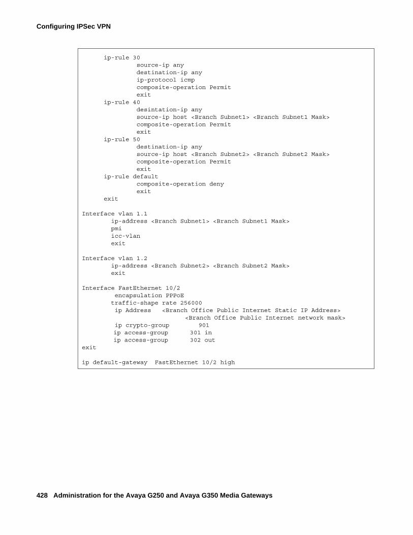
Configuring IPSec VPN
428 Administration for the Avaya G250 and Avaya G350 Media Gateways
ip-rule 30 source-ip any destination-ip any ip-protocol icmp composite-operation Permit exit ip-rule 40 desintation-ip any source-ip host <Branch Subnet1> <Branch Subnet1 Mask> composite-operation Permit exit ip-rule 50 destination-ip any source-ip host <Branch Subnet2> <Branch Subnet2 Mask> composite-operation Permit exit ip-rule default composite-operation deny exit exit
Interface vlan 1.1 ip-address <Branch Subnet1> <Branch Subnet1 Mask> pmi icc-vlan exit
Interface vlan 1.2 ip-address <Branch Subnet2> <Branch Subnet2 Mask> exit
Interface FastEthernet 10/2 encapsulation PPPoE traffic-shape rate 256000 ip Address <Branch Office Public Internet Static IP Address>
<Branch Office Public Internet network mask> ip crypto-group 901
ip access-group 301 in ip access-group 302 out
exit
ip default-gateway FastEthernet 10/2 high
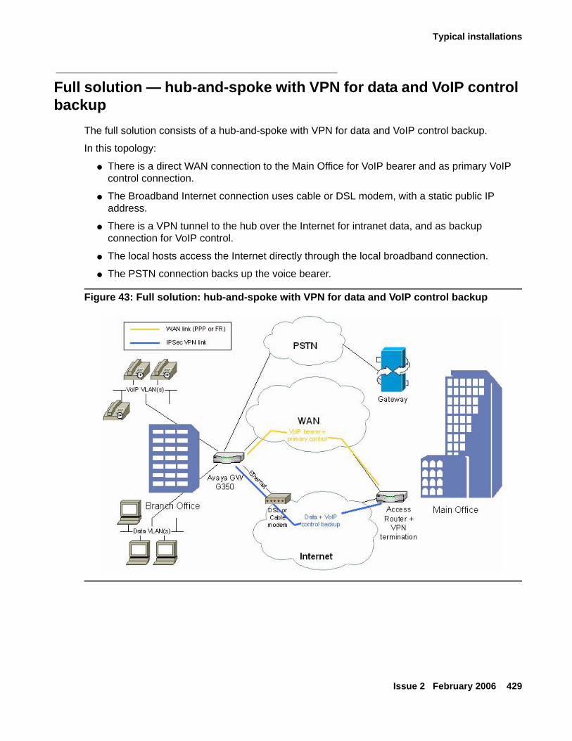
Typical installations
Issue 2 February 2006 429
Full solution — hub-and-spoke with VPN for data and VoIP control backup
The full solution consists of a hub-and-spoke with VPN for data and VoIP control backup.
In this topology:
● There is a direct WAN connection to the Main Office for VoIP bearer and as primary VoIP control connection.
● The Broadband Internet connection uses cable or DSL modem, with a static public IP address.
● There is a VPN tunnel to the hub over the Internet for intranet data, and as backup connection for VoIP control.
● The local hosts access the Internet directly through the local broadband connection.
● The PSTN connection backs up the voice bearer.
Figure 43: Full solution: hub-and-spoke with VPN for data and VoIP control backup
Configuring IPSec VPN
430 Administration for the Avaya G250 and Avaya G350 Media Gateways
Configuring hub-and-spoke with VPN for data and VoIP control backupThis section describes how to configure hub-and-spoke with VPN for data and VoIP control backup, followed by a detailed configuration example.
To configure hub-and-spoke with VPN for data and VoIP control backup:
1. Configure the Branch Office as follows:
● The default gateway is the Internet interface.
● VPN policy is configured on the Internet interface egress as follows:Traffic from the local GRE tunnel endpoint to the remote GRE tunnel endpoint -> encrypt, using IPSec tunnel mode, with the remote peer being the Main Office.
● An access control list (ACL) is configured on the Internet interface to allow only the VPN tunnel and ICMP traffic, as follows:
Note:Note: For information about using access control lists, see the chapter Configuring
policy on page 463.
Ingress:
1. IKE (UDP/500) from remote tunnel endpoint to local tunnel endpoint -> Permit
2. ESP/AH from remote tunnel endpoint to local tunnel endpoint -> Permit
3. Remote GRE tunnel endpoint to local GRE tunnel endpoint -> Permit
4. Allowed ICMP from any IP address to local tunnel endpoint -> Permit
5. Default -> Deny
Egress:
1. IKE (UDP/500) from local tunnel endpoint to remote tunnel endpoint -> Permit
2. Local GRE tunnel endpoint to remote GRE tunnel endpoint -> Permit
3. All allowed services from any local subnet to any IP address -> Permit
4. Allowed ICMP from local tunnel endpoint to any IP address -> Permit
5. Default -> Deny
● Policy Based Routing (PBR) is configured as follows, on VoIP VLAN and loopback interfaces:
Note:Note: For information about Policy-Based Routing, see the chapter Configuring
policy-based routing on page 487.
● Destination IP = local subnets -> Route: DBR
● DSCP = bearer -> Route: WAN
● DSCP = control -> Route: 1. WAN 2. DBR
Typical installations
Issue 2 February 2006 431
2. Configure the VPN Hub (Main Office) as follows:
● The VPN policy portion for the branch is configured as a mirror image of the branch.
● The ACL portion for the branch is a mirror image of the branch, with some minor modifications.
● Static routing is configured as follows:Branch subnets -> Internet interface.
● Policy Based Routing (PBR) portion for the branch is configured as follows, on most interfaces:
● Destination IP = branch VoIP subnet(s) or GW address (PMI), DSCP = bearer -> Route: WAN
● Destination IP = branch VoIP subnet(s) or GW address (PMI), DSCP = control -> Route: 1. WAN 2. DBR
● ACM is configured to route voice calls through PSTN when the main VoIP trunk is down.

Configuring IPSec VPN
432 Administration for the Avaya G250 and Avaya G350 Media Gateways
Configuration example
crypto isakmp policy 1 encryption aes hash sha group 2 authentication pre-share exitcrypto isakmp peer address <Main Office Internet public Static IP
Address> pre-shared-key <key1> isakmp-policy 1 exitcrypto ipsec transform-set ts1 esp-3des esp-sha-hmac exitcrypto map 1 set peer <Main Office Internet public Static IP Address> set transform-set ts1 exit
ip crypto-list 901 local-address <Branch Office Public Internet Static IP Address> ip-rule 10 source-ip <Branch data Subnet> <Branch data Subnet Mask> destination-ip any protect crypto map 1 exit ip-rule 20 source-ip <Branch voice Subnet> <Branch voice Subnet Mask> destination-ip any protect crypto map 1 exit
exit
ip access-control-list 301 ip-rule 10 source-ip any
destination-ip any ip-protocol udp udp destination-port eq Ike composite-operation Permit exit
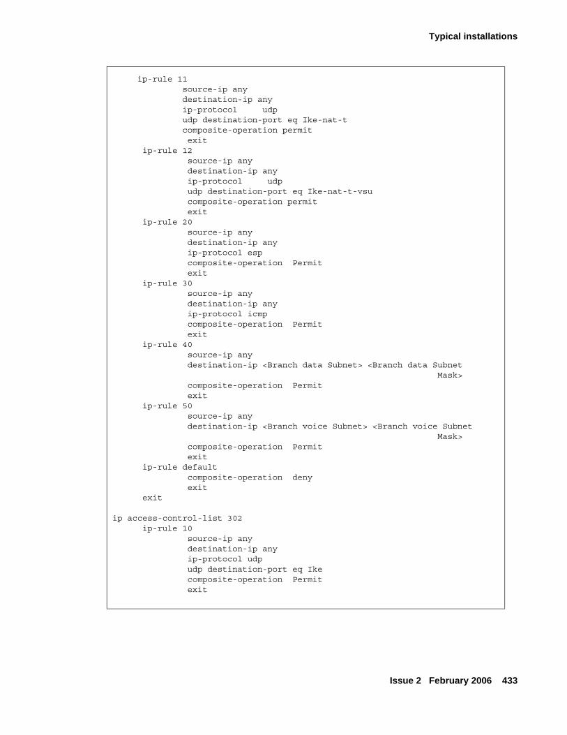
Typical installations
Issue 2 February 2006 433
ip-rule 11 source-ip any destination-ip any ip-protocol udp udp destination-port eq Ike-nat-t composite-operation permit exit ip-rule 12 source-ip any destination-ip any ip-protocol udp udp destination-port eq Ike-nat-t-vsu composite-operation permit exit ip-rule 20 source-ip any destination-ip any ip-protocol esp composite-operation Permit exit ip-rule 30 source-ip any destination-ip any ip-protocol icmp composite-operation Permit exit ip-rule 40 source-ip any destination-ip <Branch data Subnet> <Branch data Subnet
Mask> composite-operation Permit exit ip-rule 50 source-ip any destination-ip <Branch voice Subnet> <Branch voice Subnet
Mask> composite-operation Permit exit ip-rule default composite-operation deny exit exit
ip access-control-list 302 ip-rule 10 source-ip any destination-ip any ip-protocol udp udp destination-port eq Ike composite-operation Permit exit
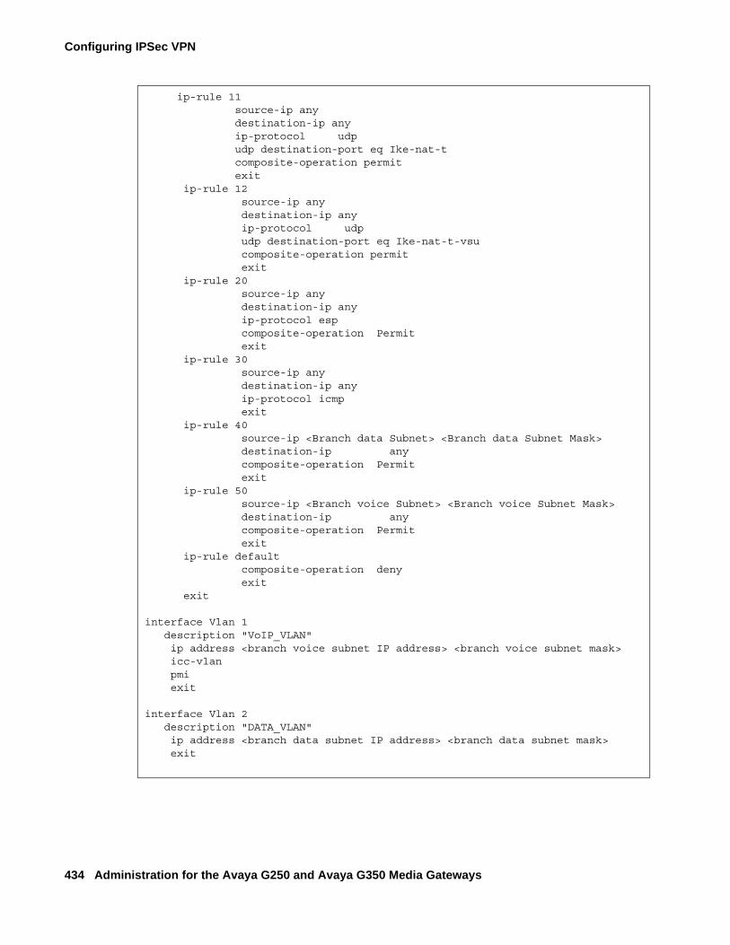
Configuring IPSec VPN
434 Administration for the Avaya G250 and Avaya G350 Media Gateways
ip-rule 11 source-ip any destination-ip any ip-protocol udp udp destination-port eq Ike-nat-t composite-operation permit exit ip-rule 12 source-ip any destination-ip any ip-protocol udp udp destination-port eq Ike-nat-t-vsu composite-operation permit exit ip-rule 20 source-ip any destination-ip any ip-protocol esp composite-operation Permit exit ip-rule 30 source-ip any destination-ip any ip-protocol icmp exit ip-rule 40 source-ip <Branch data Subnet> <Branch data Subnet Mask> destination-ip any composite-operation Permit exit ip-rule 50 source-ip <Branch voice Subnet> <Branch voice Subnet Mask> destination-ip any composite-operation Permit exit ip-rule default composite-operation deny exit exit
interface Vlan 1 description "VoIP_VLAN" ip address <branch voice subnet IP address> <branch voice subnet mask> icc-vlan pmi exit
interface Vlan 2 description "DATA_VLAN" ip address <branch data subnet IP address> <branch data subnet mask> exit
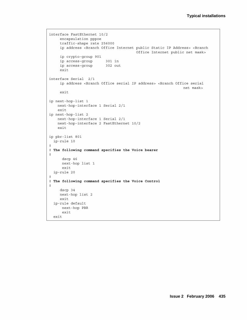
Typical installations
Issue 2 February 2006 435
interface FastEthernet 10/2 encapsulation pppoe traffic-shape rate 256000 ip address <Branch Office Internet public Static IP Address> <Branch
Office Internet public net mask> ip crypto-group 901 ip access-group 301 in ip access-group 302 out exit
interface Serial 2/1 ip address <Branch Office serial IP address> <Branch Office serial
net mask> exit
ip next-hop-list 1 next-hop-interface 1 Serial 2/1 exitip next-hop-list 2 next-hop-interface 1 Serial 2/1 next-hop-interface 2 FastEthernet 10/2 exit
ip pbr-list 801 ip-rule 10!! The following command specifies the Voice bearer!
dscp 46 next-hop list 1 exit ip-rule 20!! The following command specifies the Voice Control! dscp 34 next-hop list 2 exit ip-rule default next-hop PBR exit exit
Configuring IPSec VPN
436 Administration for the Avaya G250 and Avaya G350 Media Gateways
Typical failover applications
Introduction to the failover mechanism
The failover mechanism provides switchover to backup peers in case of remote peer failure. To enable the failover mechanism, you must:
● Configure VPN keepalives, which check the remote peer periodically and announce when the remote peer is dead.
● Provide backup peers and a mechanism for switching to a backup in case of remote peer failure.
In addition to the GRE failover mechanism (see Failover using GRE on page 437), the G250/G350 supports several additional failover mechanisms, as described below.
Configuring VPN keepalivesVPN keepalives can dramatically improve the speed with which the G250/G350 detects loss of connectivity with the remote VPN peer. Two types of VPN keepalives are available. You can use either or both methods:
● Enable DPD (Dead Peer Detection) keepalives, a standard VPN keepalive, that check whether the remote peer is up. This type of detection can be used only if it is supported also by the remote peer.
● Bind peer status to an object tracker. Object trackers track the state (up/down) of remote devices using keepalive probes, and notify registered applications such as VPN when the state changes. Object tracking allows monitoring of hosts inside the remote peer’s protected network, not just of the remote peer itself as in DPD.
Backup peer mechanismYou can use any one of these alternate backup peer mechanisms:
● DNS server (see Failover using DNS on page 444). This method utilizes the G250/G350’s DNS Resolver capability for dynamically resolving a remote peer’s IP address via a DNS query.
Use this feature when your DNS server supports failover through health-checking of redundant hosts. On your DNS server configure a hostname to translate to two or more redundant hosts, which act as redundant VPN peers. On the G250/G350 configure that hostname as your remote peer. The G250/G350 will perform a DNS query in order to resolve the hostname to an IP address before establishing an IKE connection. Your DNS server should be able to provide an IP address of a living host. The G250/G350 will perform a new DNS query and try to re-establish the VPN connection to the newly provided IP address whenever it senses that the currently active remote peer stopped responding. The G250/G350 can sense that a peer is dead when IKE negotiation times-out, through DPD keepalives, and through object tracking.
Typical installations
Issue 2 February 2006 437
● Using the G250/G350’s peer-group entity (see Failover using a peer-group on page 452):
a. Define a peer-group. A peer-group is an ordered list of redundant remote peers, only one of which is active at any time. When the active peer is considered dead, the next peer in the list becomes the active remote peer.
b. When configuring a crypto map, point to the peer-group instead of to a single peer.
Failover using GRE
A branch with a G250/G350 can connect to two or more VPN hub sites, in a way that will provide either redundancy or load sharing.
In this topology, the G250/G350 is connected through its 10/100 WAN Ethernet port to a DSL modem.
● Define two GRE tunnel interfaces:● GRE1 that leads to a Primary Main Office GRE End Point behind the VPN Hub Gateway ● GRE2 that leads to a Backup Main Office GRE End Point behind the VPN Hub Gateway
● Define two VPNs.● Connectivity to the networks in Primary/Backup Main Office is determined through GRE
keep alives. If network connectivity is lost due to failures in the WAN, in the Primary Main Office, the GRE keep-alive will fail and the GRE interface will transition to a “down” state.
The two GRE tunnels can then be used for branch to Primary/Backup Main Office in either Redundancy or Load sharing mode:
● Redundancy – GRE2 is configured as a backup interface for GRE1, and is activated only when GRE1 is down.
● Load sharing – Both tunnel interfaces are active. Routing protocols (RIP or OSPF) route traffic to destinations based on route cost & availability, as follows:
For two routes of equal cost to the same destination, one through the Primary Main Office and one through the Backup Main Office, OSPF will automatically distribute traffic through both routes, effectively sharing the load between routes.
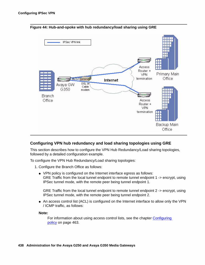
Configuring IPSec VPN
438 Administration for the Avaya G250 and Avaya G350 Media Gateways
Figure 44: Hub-and-spoke with hub redundancy/load sharing using GRE
Configuring VPN hub redundancy and load sharing topologies using GREThis section describes how to configure the VPN Hub Redundancy/Load sharing topologies, followed by a detailed configuration example.
To configure the VPN Hub Redundancy/Load sharing topologies:
1. Configure the Branch Office as follows:
● VPN policy is configured on the Internet interface egress as follows:GRE Traffic from the local tunnel endpoint to remote tunnel endpoint 1 -> encrypt, using IPSec tunnel mode, with the remote peer being tunnel endpoint 1.
GRE Traffic from the local tunnel endpoint to remote tunnel endpoint 2 -> encrypt, using IPSec tunnel mode, with the remote peer being tunnel endpoint 2.
● An access control list (ACL) is configured on the Internet interface to allow only the VPN / ICMP traffic, as follows:
Note:Note: For information about using access control lists, see the chapter Configuring
policy on page 463.
Typical installations
Issue 2 February 2006 439
Ingress:
1. IKE (UDP/500) from remote tunnel endpoints to local tunnel endpoint -> Permit
2. ESP/AH from remote tunnel endpoint to local tunnel endpoint -> Permit
3. Allowed ICMP from any IP address to local tunnel endpoint -> Permit
4. Default -> Deny
Egress:
1. IKE (UDP/500) from local tunnel endpoint to remote tunnel endpoint -> Permit
2. All allowed services from any local subnet to any IP address-> Permit
3. Allowed ICMP from local tunnel endpoint to any IP address -> Permit
4. Default -> Deny
● Configure dynamic routing (OSPF or RIP) to run over local data interfaces (data VLANs) and on the GRE interfaces.
2. Configure the VPN Hubs (Main Offices) as follows:
● The VPN policy portion for the branch is configured as a mirror image of the branch.
● The ACL portion for the branch is a mirror image of the branch, with some minor modifications.
● The GRE tunnel interface is configured for the branch.
● Dynamic routing (OSPF or RIP) is configured to run over the GRE interface to the branch.
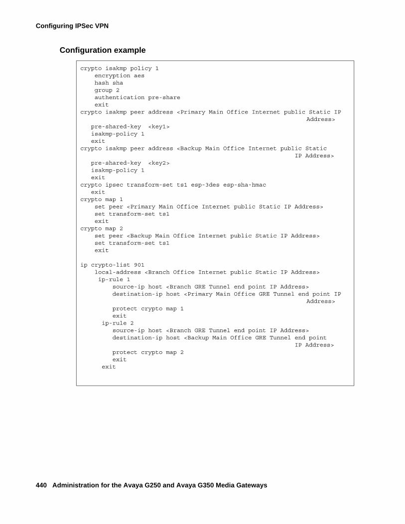
Configuring IPSec VPN
440 Administration for the Avaya G250 and Avaya G350 Media Gateways
Configuration example
crypto isakmp policy 1 encryption aes hash sha group 2 authentication pre-share exitcrypto isakmp peer address <Primary Main Office Internet public Static IP
Address> pre-shared-key <key1> isakmp-policy 1 exitcrypto isakmp peer address <Backup Main Office Internet public Static
IP Address> pre-shared-key <key2> isakmp-policy 1 exitcrypto ipsec transform-set ts1 esp-3des esp-sha-hmac exitcrypto map 1 set peer <Primary Main Office Internet public Static IP Address> set transform-set ts1 exitcrypto map 2 set peer <Backup Main Office Internet public Static IP Address> set transform-set ts1 exit
ip crypto-list 901 local-address <Branch Office Internet public Static IP Address> ip-rule 1 source-ip host <Branch GRE Tunnel end point IP Address> destination-ip host <Primary Main Office GRE Tunnel end point IP
Address> protect crypto map 1 exit ip-rule 2 source-ip host <Branch GRE Tunnel end point IP Address> destination-ip host <Backup Main Office GRE Tunnel end point
IP Address> protect crypto map 2 exit exit
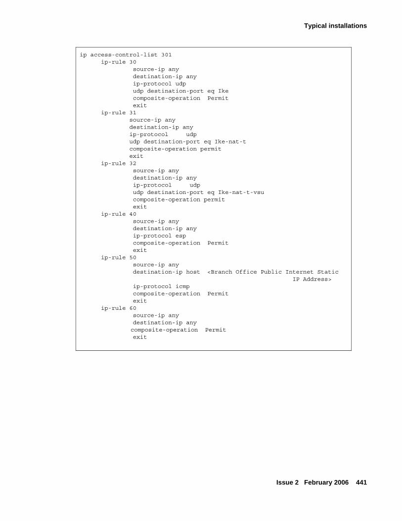
Typical installations
Issue 2 February 2006 441
ip access-control-list 301 ip-rule 30 source-ip any destination-ip any ip-protocol udp udp destination-port eq Ike composite-operation Permit exit ip-rule 31 source-ip any destination-ip any ip-protocol udp udp destination-port eq Ike-nat-t composite-operation permit exit ip-rule 32 source-ip any destination-ip any ip-protocol udp udp destination-port eq Ike-nat-t-vsu composite-operation permit exit ip-rule 40 source-ip any destination-ip any ip-protocol esp composite-operation Permit exit ip-rule 50 source-ip any destination-ip host <Branch Office Public Internet Static
IP Address> ip-protocol icmp composite-operation Permit exit ip-rule 60 source-ip any destination-ip any
composite-operation Permit exit
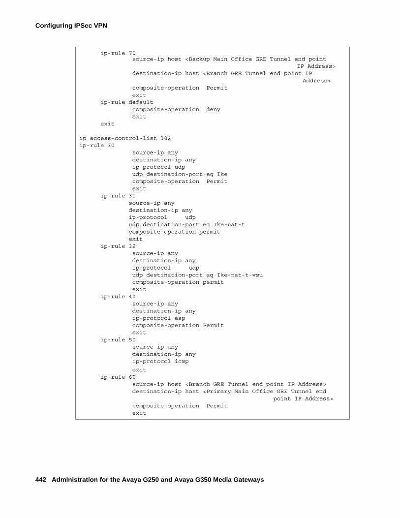
Configuring IPSec VPN
442 Administration for the Avaya G250 and Avaya G350 Media Gateways
ip-rule 70 source-ip host <Backup Main Office GRE Tunnel end point
IP Address>destination-ip host <Branch GRE Tunnel end point IP
Address> composite-operation Permit exit ip-rule default composite-operation deny exit exit
ip access-control-list 302 ip-rule 30 source-ip any destination-ip any ip-protocol udp udp destination-port eq Ike composite-operation Permit exit ip-rule 31 source-ip any destination-ip any ip-protocol udp udp destination-port eq Ike-nat-t composite-operation permit exit ip-rule 32 source-ip any destination-ip any ip-protocol udp udp destination-port eq Ike-nat-t-vsu composite-operation permit exit ip-rule 40 source-ip any destination-ip any ip-protocol esp composite-operation Permit exit ip-rule 50 source-ip any destination-ip any ip-protocol icmp
exit ip-rule 60 source-ip host <Branch GRE Tunnel end point IP Address> destination-ip host <Primary Main Office GRE Tunnel end
point IP Address> composite-operation Permit exit
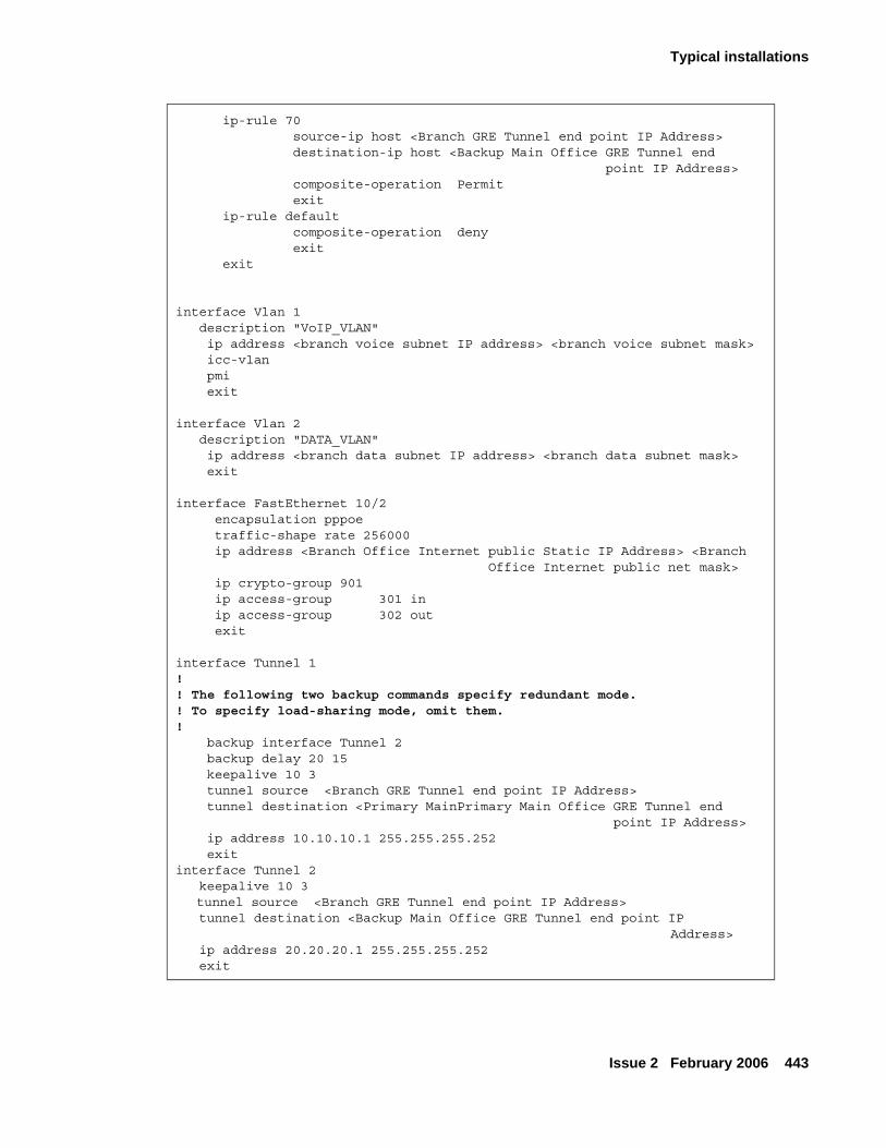
Typical installations
Issue 2 February 2006 443
ip-rule 70 source-ip host <Branch GRE Tunnel end point IP Address> destination-ip host <Backup Main Office GRE Tunnel end
point IP Address> composite-operation Permit exit ip-rule default composite-operation deny exit exit
interface Vlan 1 description "VoIP_VLAN" ip address <branch voice subnet IP address> <branch voice subnet mask> icc-vlan pmi exit
interface Vlan 2 description "DATA_VLAN" ip address <branch data subnet IP address> <branch data subnet mask> exit
interface FastEthernet 10/2 encapsulation pppoe traffic-shape rate 256000 ip address <Branch Office Internet public Static IP Address> <Branch
Office Internet public net mask> ip crypto-group 901 ip access-group 301 in ip access-group 302 out exit
interface Tunnel 1!! The following two backup commands specify redundant mode.! To specify load-sharing mode, omit them. ! backup interface Tunnel 2 backup delay 20 15 keepalive 10 3 tunnel source <Branch GRE Tunnel end point IP Address> tunnel destination <Primary MainPrimary Main Office GRE Tunnel end
point IP Address> ip address 10.10.10.1 255.255.255.252 exitinterface Tunnel 2 keepalive 10 3 tunnel source <Branch GRE Tunnel end point IP Address>
tunnel destination <Backup Main Office GRE Tunnel end point IP Address>
ip address 20.20.20.1 255.255.255.252 exit
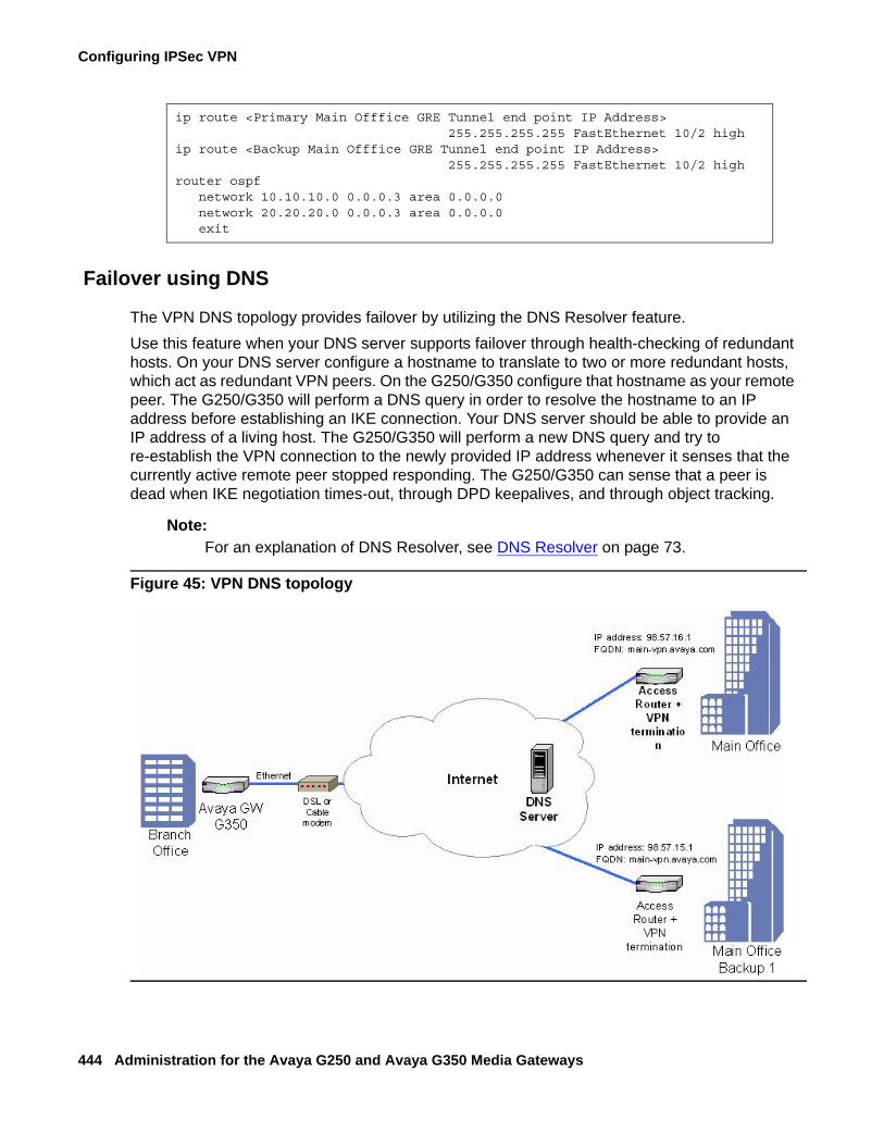
Configuring IPSec VPN
444 Administration for the Avaya G250 and Avaya G350 Media Gateways
Failover using DNS
The VPN DNS topology provides failover by utilizing the DNS Resolver feature.Use this feature when your DNS server supports failover through health-checking of redundant hosts. On your DNS server configure a hostname to translate to two or more redundant hosts, which act as redundant VPN peers. On the G250/G350 configure that hostname as your remote peer. The G250/G350 will perform a DNS query in order to resolve the hostname to an IP address before establishing an IKE connection. Your DNS server should be able to provide an IP address of a living host. The G250/G350 will perform a new DNS query and try to re-establish the VPN connection to the newly provided IP address whenever it senses that the currently active remote peer stopped responding. The G250/G350 can sense that a peer is dead when IKE negotiation times-out, through DPD keepalives, and through object tracking.
Note:Note: For an explanation of DNS Resolver, see DNS Resolver on page 73.
Figure 45: VPN DNS topology
ip route <Primary Main Offfice GRE Tunnel end point IP Address> 255.255.255.255 FastEthernet 10/2 high
ip route <Backup Main Offfice GRE Tunnel end point IP Address> 255.255.255.255 FastEthernet 10/2 high
router ospf network 10.10.10.0 0.0.0.3 area 0.0.0.0 network 20.20.20.0 0.0.0.3 area 0.0.0.0 exit
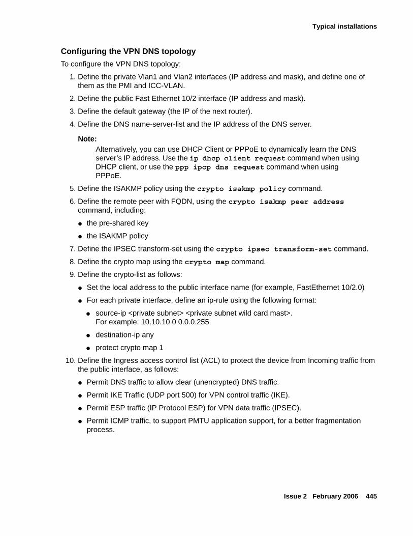
Typical installations
Issue 2 February 2006 445
Configuring the VPN DNS topologyTo configure the VPN DNS topology:
1. Define the private Vlan1 and Vlan2 interfaces (IP address and mask), and define one of them as the PMI and ICC-VLAN.
2. Define the public Fast Ethernet 10/2 interface (IP address and mask).
3. Define the default gateway (the IP of the next router).
4. Define the DNS name-server-list and the IP address of the DNS server.
Note:Note: Alternatively, you can use DHCP Client or PPPoE to dynamically learn the DNS
server’s IP address. Use the ip dhcp client request command when using DHCP client, or use the ppp ipcp dns request command when using PPPoE.
5. Define the ISAKMP policy using the crypto isakmp policy command.
6. Define the remote peer with FQDN, using the crypto isakmp peer address command, including:
● the pre-shared key
● the ISAKMP policy
7. Define the IPSEC transform-set using the crypto ipsec transform-set command.
8. Define the crypto map using the crypto map command.
9. Define the crypto-list as follows:
● Set the local address to the public interface name (for example, FastEthernet 10/2.0)
● For each private interface, define an ip-rule using the following format:
● source-ip <private subnet> <private subnet wild card mast>. For example: 10.10.10.0 0.0.0.255
● destination-ip any
● protect crypto map 1
10. Define the Ingress access control list (ACL) to protect the device from Incoming traffic from the public interface, as follows:
● Permit DNS traffic to allow clear (unencrypted) DNS traffic.
● Permit IKE Traffic (UDP port 500) for VPN control traffic (IKE).
● Permit ESP traffic (IP Protocol ESP) for VPN data traffic (IPSEC).
● Permit ICMP traffic, to support PMTU application support, for a better fragmentation process.
Configuring IPSec VPN
446 Administration for the Avaya G250 and Avaya G350 Media Gateways
● For each private subnet, add a permit rule, with the destination being the private subnet, and the source being any. This traffic will be allowed only if it tunnels under the VPN, because of the crypto-list.
● Define all other traffic (default rule) as deny in order to protect the device from non-secure traffic.
11. Define the Egress access control list to protect the device from sending traffic that is not allowed to the public interface (optional):
● Permit DNS traffic to allow clear (unencrypted) DNS traffic.
● Permit IKE Traffic (UDP port 500) for VPN control traffic (IKE).
● Permit ESP traffic (IP Protocol ESP) for VPN data traffic (IPSEC).
● Permit ICMP traffic, to support PMTU application support, for a better fragmentation process.
● For each private subnet, add a permit rule, with the source being the private subnet, and the destination being any.
● Define all other traffic (default rule) as deny in order to protect the device from sending non-secure traffic.
12. Activate the crypto-list, the Ingress access control list, and the Egress access control list, on the public interface.
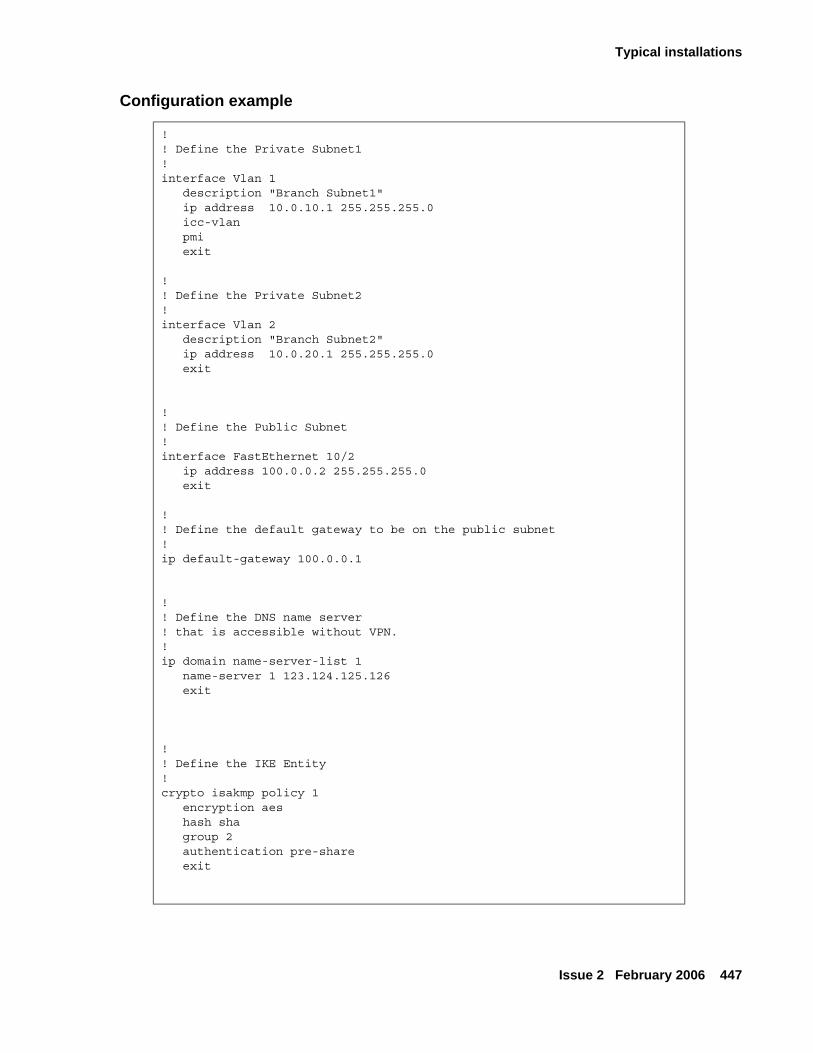
Typical installations
Issue 2 February 2006 447
Configuration example
! ! Define the Private Subnet1 !interface Vlan 1 description "Branch Subnet1" ip address 10.0.10.1 255.255.255.0 icc-vlan pmi exit ! ! Define the Private Subnet2!interface Vlan 2 description "Branch Subnet2" ip address 10.0.20.1 255.255.255.0 exit
! ! Define the Public Subnet !interface FastEthernet 10/2 ip address 100.0.0.2 255.255.255.0 exit !! Define the default gateway to be on the public subnet !ip default-gateway 100.0.0.1
!! Define the DNS name server ! that is accessible without VPN.!ip domain name-server-list 1 name-server 1 123.124.125.126 exit !! Define the IKE Entity !crypto isakmp policy 1 encryption aes hash sha group 2 authentication pre-share exit
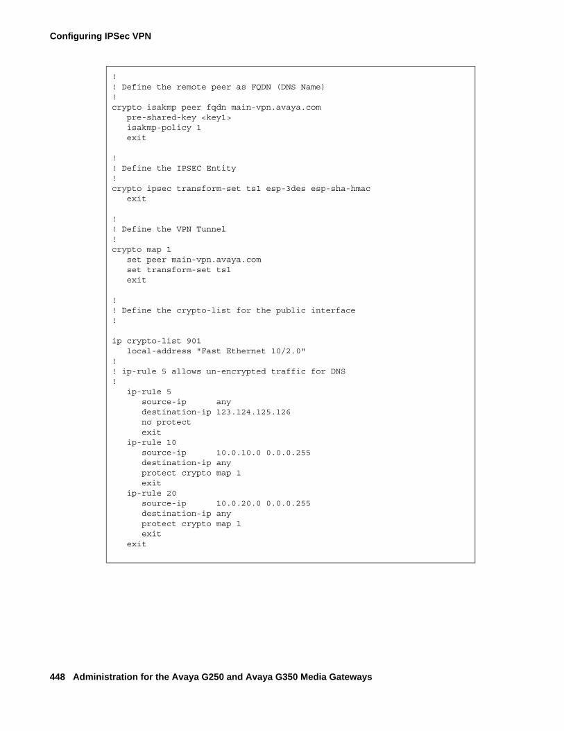
Configuring IPSec VPN
448 Administration for the Avaya G250 and Avaya G350 Media Gateways
!! Define the remote peer as FQDN (DNS Name) !crypto isakmp peer fqdn main-vpn.avaya.com pre-shared-key <key1> isakmp-policy 1 exit !! Define the IPSEC Entity !crypto ipsec transform-set ts1 esp-3des esp-sha-hmac exit !! Define the VPN Tunnel ! crypto map 1 set peer main-vpn.avaya.com set transform-set ts1 exit !! Define the crypto-list for the public interface! ip crypto-list 901 local-address "Fast Ethernet 10/2.0" !! ip-rule 5 allows un-encrypted traffic for DNS! ip-rule 5 source-ip any destination-ip 123.124.125.126 no protect exit ip-rule 10 source-ip 10.0.10.0 0.0.0.255 destination-ip any protect crypto map 1 exit ip-rule 20 source-ip 10.0.20.0 0.0.0.255 destination-ip any protect crypto map 1 exit
exit
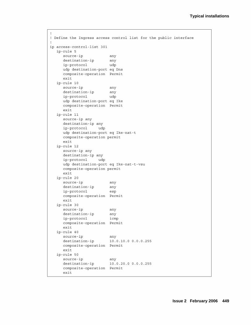
Typical installations
Issue 2 February 2006 449
!! Define the Ingress access control list for the public interface!ip access-control-list 301 ip-rule 5 source-ip any destination-ip any ip-protocol udp udp destination-port eq Dns composite-operation Permit exit ip-rule 10 source-ip any destination-ip any ip-protocol udp udp destination-port eq Ike composite-operation Permit exit ip-rule 11 source-ip any destination-ip any ip-protocol udp udp destination-port eq Ike-nat-t composite-operation permit exit ip-rule 12 source-ip any destination-ip any ip-protocol udp udp destination-port eq Ike-nat-t-vsu composite-operation permit exit ip-rule 20 source-ip any destination-ip any ip-protocol esp composite-operation Permit exit ip-rule 30 source-ip any destination-ip any ip-protocol icmp composite-operation Permit exit ip-rule 40 source-ip any destination-ip 10.0.10.0 0.0.0.255 composite-operation Permit exit ip-rule 50 source-ip any destination-ip 10.0.20.0 0.0.0.255 composite-operation Permit exit
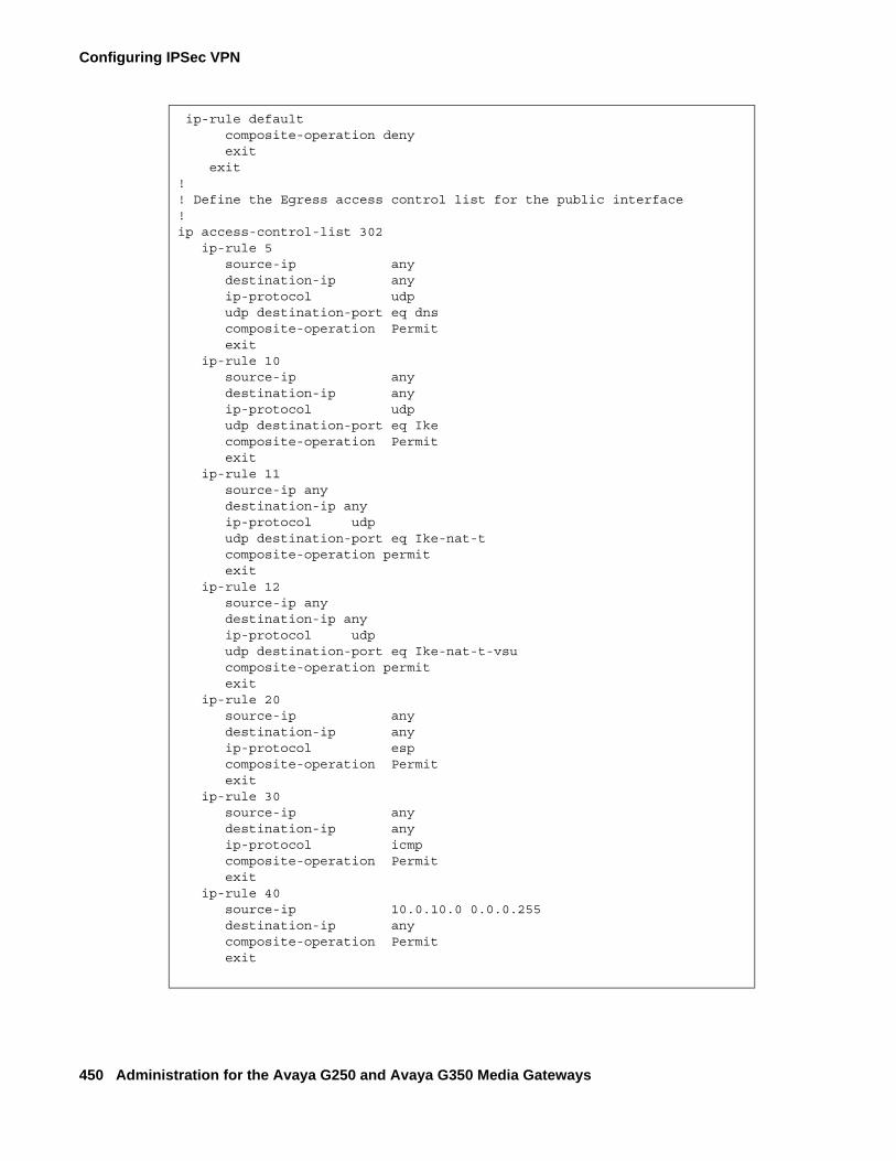
Configuring IPSec VPN
450 Administration for the Avaya G250 and Avaya G350 Media Gateways
ip-rule default composite-operation deny exit exit!! Define the Egress access control list for the public interface!ip access-control-list 302 ip-rule 5 source-ip any destination-ip any ip-protocol udp udp destination-port eq dns composite-operation Permit exit ip-rule 10 source-ip any destination-ip any ip-protocol udp udp destination-port eq Ike composite-operation Permit exit ip-rule 11 source-ip any destination-ip any ip-protocol udp udp destination-port eq Ike-nat-t composite-operation permit exit ip-rule 12 source-ip any destination-ip any ip-protocol udp udp destination-port eq Ike-nat-t-vsu composite-operation permit exit ip-rule 20 source-ip any destination-ip any ip-protocol esp composite-operation Permit exit ip-rule 30 source-ip any destination-ip any ip-protocol icmp composite-operation Permit exit ip-rule 40 source-ip 10.0.10.0 0.0.0.255 destination-ip any composite-operation Permit exit
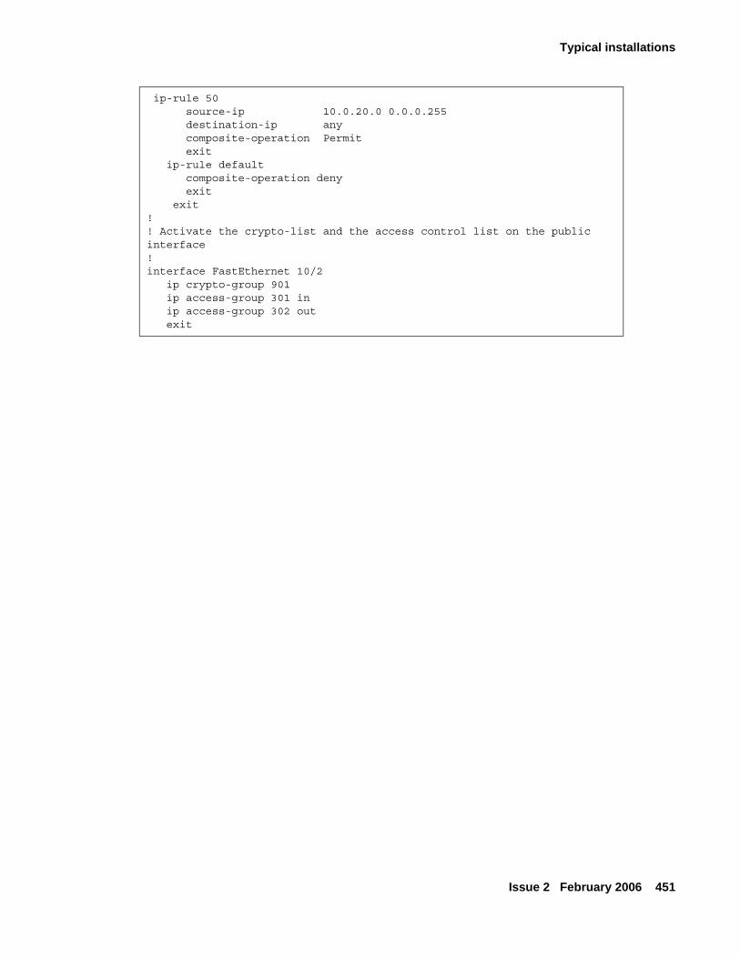
Typical installations
Issue 2 February 2006 451
ip-rule 50 source-ip 10.0.20.0 0.0.0.255 destination-ip any composite-operation Permit exit ip-rule default composite-operation deny exit exit! ! Activate the crypto-list and the access control list on the public interface!interface FastEthernet 10/2 ip crypto-group 901 ip access-group 301 in ip access-group 302 out exit
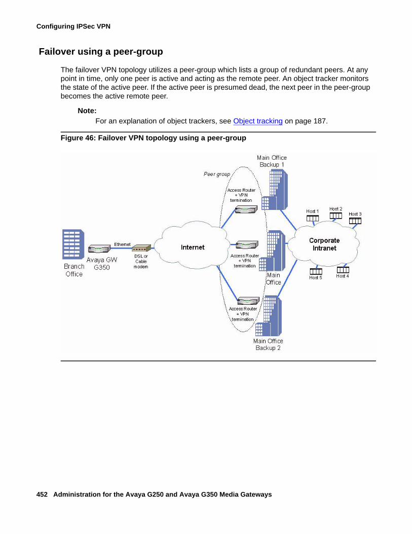
Configuring IPSec VPN
452 Administration for the Avaya G250 and Avaya G350 Media Gateways
Failover using a peer-group
The failover VPN topology utilizes a peer-group which lists a group of redundant peers. At any point in time, only one peer is active and acting as the remote peer. An object tracker monitors the state of the active peer. If the active peer is presumed dead, the next peer in the peer-group becomes the active remote peer.
Note:Note: For an explanation of object trackers, see Object tracking on page 187.
Figure 46: Failover VPN topology using a peer-group
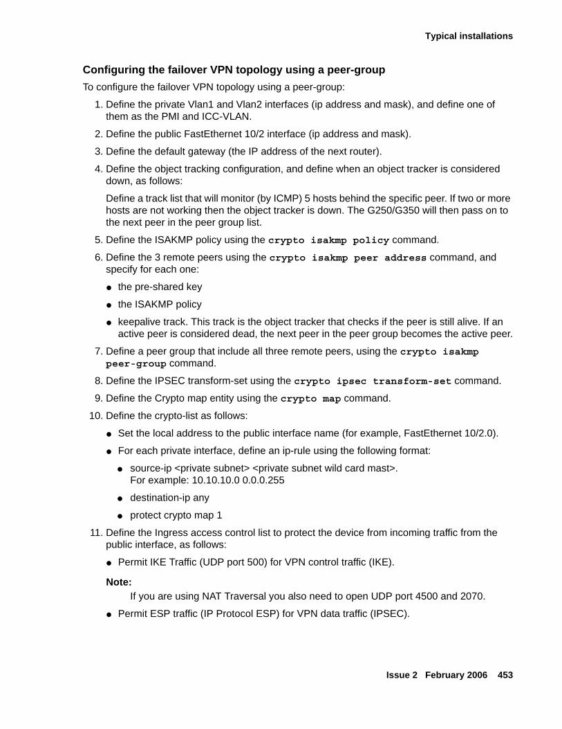
Typical installations
Issue 2 February 2006 453
Configuring the failover VPN topology using a peer-groupTo configure the failover VPN topology using a peer-group:
1. Define the private Vlan1 and Vlan2 interfaces (ip address and mask), and define one of them as the PMI and ICC-VLAN.
2. Define the public FastEthernet 10/2 interface (ip address and mask).
3. Define the default gateway (the IP address of the next router).
4. Define the object tracking configuration, and define when an object tracker is considered down, as follows:
Define a track list that will monitor (by ICMP) 5 hosts behind the specific peer. If two or more hosts are not working then the object tracker is down. The G250/G350 will then pass on to the next peer in the peer group list.
5. Define the ISAKMP policy using the crypto isakmp policy command.
6. Define the 3 remote peers using the crypto isakmp peer address command, and specify for each one:
● the pre-shared key
● the ISAKMP policy
● keepalive track. This track is the object tracker that checks if the peer is still alive. If an active peer is considered dead, the next peer in the peer group becomes the active peer.
7. Define a peer group that include all three remote peers, using the crypto isakmp peer-group command.
8. Define the IPSEC transform-set using the crypto ipsec transform-set command.
9. Define the Crypto map entity using the crypto map command.
10. Define the crypto-list as follows:
● Set the local address to the public interface name (for example, FastEthernet 10/2.0).
● For each private interface, define an ip-rule using the following format:
● source-ip <private subnet> <private subnet wild card mast>. For example: 10.10.10.0 0.0.0.255
● destination-ip any
● protect crypto map 1
11. Define the Ingress access control list to protect the device from incoming traffic from the public interface, as follows:
● Permit IKE Traffic (UDP port 500) for VPN control traffic (IKE).
Note:Note: If you are using NAT Traversal you also need to open UDP port 4500 and 2070.
● Permit ESP traffic (IP Protocol ESP) for VPN data traffic (IPSEC).
Configuring IPSec VPN
454 Administration for the Avaya G250 and Avaya G350 Media Gateways
● Permit ICMP traffic, to support PMTU application support, for a better fragmentation process.
● For each private subnet, add a permit rule, with the destination being the private subnet, and the source being any. This traffic will be allowed only if it tunnels under the VPN, because of the crypto-list.
● Define all other traffic (default rule) as deny in order to protect the device from non-secure traffic.
12. Define the Egress access control list to protect the device from sending traffic that is not allowed to the public interface (optional):
● Permit IKE Traffic (UDP port 500) for VPN control traffic (IKE).
Note:Note: If you are using NAT Traversal you also need to open UDP port 4500 and 2070
● Permit ESP traffic (IP Protocol ESP) for VPN data traffic (IPSEC)
● Permit ICMP traffic, to support the PMTU application, for a better fragmentation process.
● For each private subnet add a permit rule, with the source being the private subnet, and the destination being any.
● Define all other traffic (default rule) as deny in order to protect the device from sending non-secure traffic.
13. Activate the crypto-list, the Ingress access control list, and the Egress access control list, on the public interface.
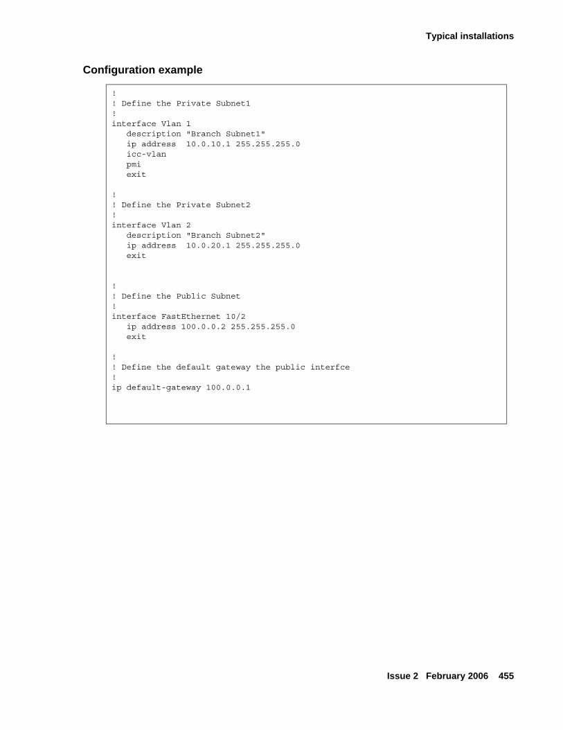
Typical installations
Issue 2 February 2006 455
Configuration example
! ! Define the Private Subnet1 !interface Vlan 1 description "Branch Subnet1" ip address 10.0.10.1 255.255.255.0 icc-vlan pmi exit ! ! Define the Private Subnet2!interface Vlan 2 description "Branch Subnet2" ip address 10.0.20.1 255.255.255.0 exit
! ! Define the Public Subnet !interface FastEthernet 10/2 ip address 100.0.0.2 255.255.255.0 exit !! Define the default gateway the public interfce !ip default-gateway 100.0.0.1
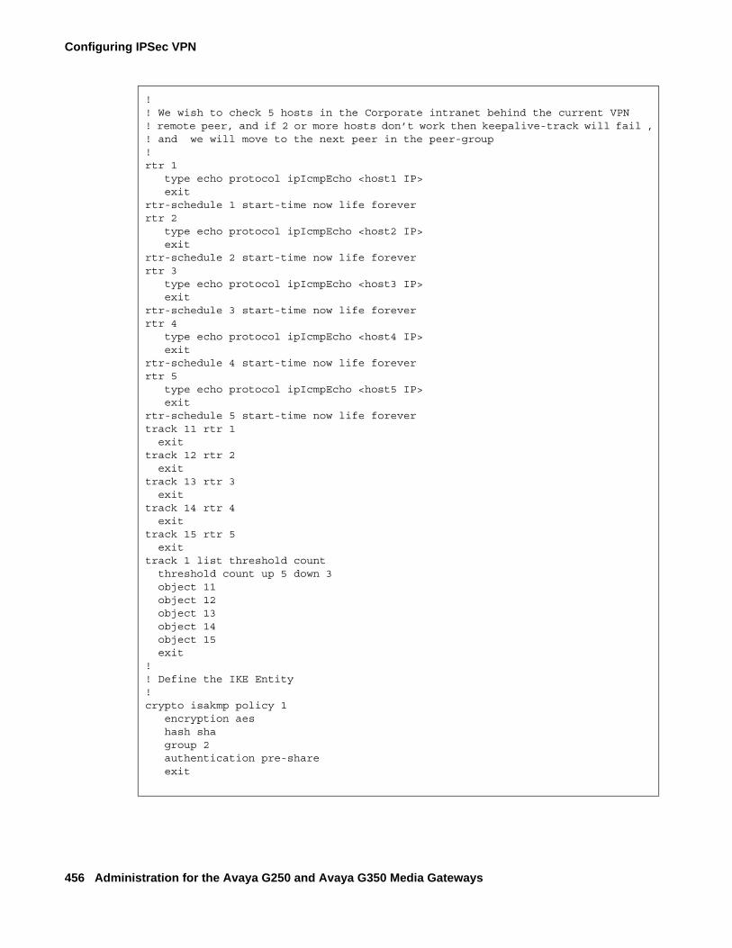
Configuring IPSec VPN
456 Administration for the Avaya G250 and Avaya G350 Media Gateways
!! We wish to check 5 hosts in the Corporate intranet behind the current VPN ! remote peer, and if 2 or more hosts don’t work then keepalive-track will fail , ! and we will move to the next peer in the peer-group!rtr 1 type echo protocol ipIcmpEcho <host1 IP> exitrtr-schedule 1 start-time now life foreverrtr 2 type echo protocol ipIcmpEcho <host2 IP> exitrtr-schedule 2 start-time now life foreverrtr 3 type echo protocol ipIcmpEcho <host3 IP> exitrtr-schedule 3 start-time now life foreverrtr 4 type echo protocol ipIcmpEcho <host4 IP> exitrtr-schedule 4 start-time now life foreverrtr 5 type echo protocol ipIcmpEcho <host5 IP> exitrtr-schedule 5 start-time now life forevertrack 11 rtr 1 exittrack 12 rtr 2 exittrack 13 rtr 3 exittrack 14 rtr 4 exittrack 15 rtr 5 exit track 1 list threshold count
threshold count up 5 down 3 object 11 object 12 object 13 object 14 object 15 exit!! Define the IKE Entity !crypto isakmp policy 1 encryption aes hash sha group 2 authentication pre-share exit
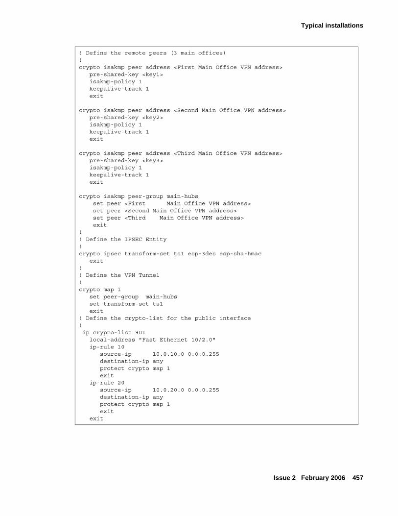
Typical installations
Issue 2 February 2006 457
! Define the remote peers (3 main offices)!crypto isakmp peer address <First Main Office VPN address> pre-shared-key <key1> isakmp-policy 1 keepalive-track 1 exit crypto isakmp peer address <Second Main Office VPN address> pre-shared-key <key2> isakmp-policy 1 keepalive-track 1 exit crypto isakmp peer address <Third Main Office VPN address> pre-shared-key <key3> isakmp-policy 1 keepalive-track 1 exit crypto isakmp peer-group main-hubs set peer <First Main Office VPN address> set peer <Second Main Office VPN address> set peer <Third Main Office VPN address> exit!! Define the IPSEC Entity !crypto ipsec transform-set ts1 esp-3des esp-sha-hmac exit!! Define the VPN Tunnel ! crypto map 1 set peer-group main-hubs set transform-set ts1 exit! Define the crypto-list for the public interface! ip crypto-list 901 local-address "Fast Ethernet 10/2.0" ip-rule 10 source-ip 10.0.10.0 0.0.0.255 destination-ip any protect crypto map 1 exit ip-rule 20 source-ip 10.0.20.0 0.0.0.255 destination-ip any protect crypto map 1 exit
exit
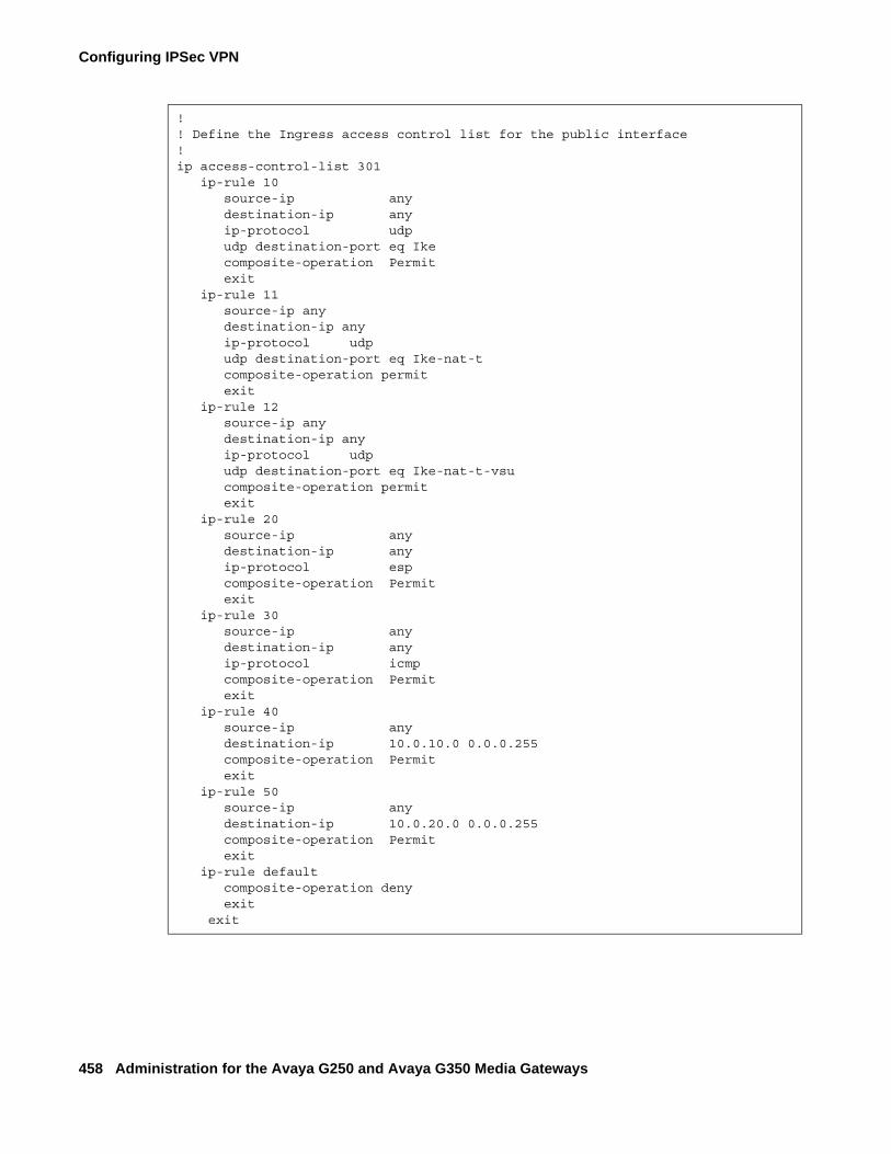
Configuring IPSec VPN
458 Administration for the Avaya G250 and Avaya G350 Media Gateways
!! Define the Ingress access control list for the public interface!ip access-control-list 301 ip-rule 10 source-ip any destination-ip any ip-protocol udp udp destination-port eq Ike composite-operation Permit exit ip-rule 11 source-ip any destination-ip any ip-protocol udp udp destination-port eq Ike-nat-t composite-operation permit exit ip-rule 12 source-ip any destination-ip any ip-protocol udp udp destination-port eq Ike-nat-t-vsu composite-operation permit exit ip-rule 20 source-ip any destination-ip any ip-protocol esp composite-operation Permit exit ip-rule 30 source-ip any destination-ip any ip-protocol icmp composite-operation Permit exit ip-rule 40 source-ip any destination-ip 10.0.10.0 0.0.0.255 composite-operation Permit exit ip-rule 50 source-ip any destination-ip 10.0.20.0 0.0.0.255 composite-operation Permit exit ip-rule default composite-operation deny exit exit
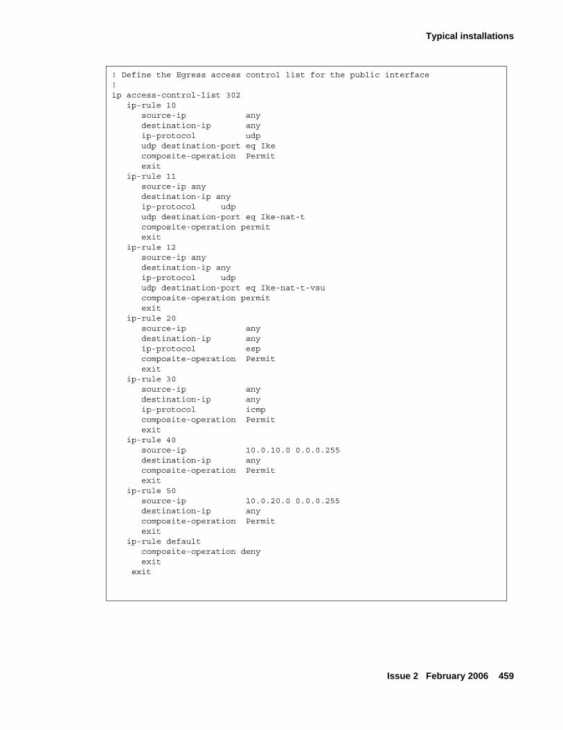
Typical installations
Issue 2 February 2006 459
! Define the Egress access control list for the public interface!ip access-control-list 302 ip-rule 10 source-ip any destination-ip any ip-protocol udp udp destination-port eq Ike composite-operation Permit exit ip-rule 11 source-ip any destination-ip any ip-protocol udp udp destination-port eq Ike-nat-t composite-operation permit exit ip-rule 12 source-ip any destination-ip any ip-protocol udp udp destination-port eq Ike-nat-t-vsu composite-operation permit exit ip-rule 20 source-ip any destination-ip any ip-protocol esp composite-operation Permit exit ip-rule 30 source-ip any destination-ip any ip-protocol icmp composite-operation Permit exit ip-rule 40 source-ip 10.0.10.0 0.0.0.255 destination-ip any composite-operation Permit exit ip-rule 50 source-ip 10.0.20.0 0.0.0.255 destination-ip any composite-operation Permit exit ip-rule default composite-operation deny exit exit
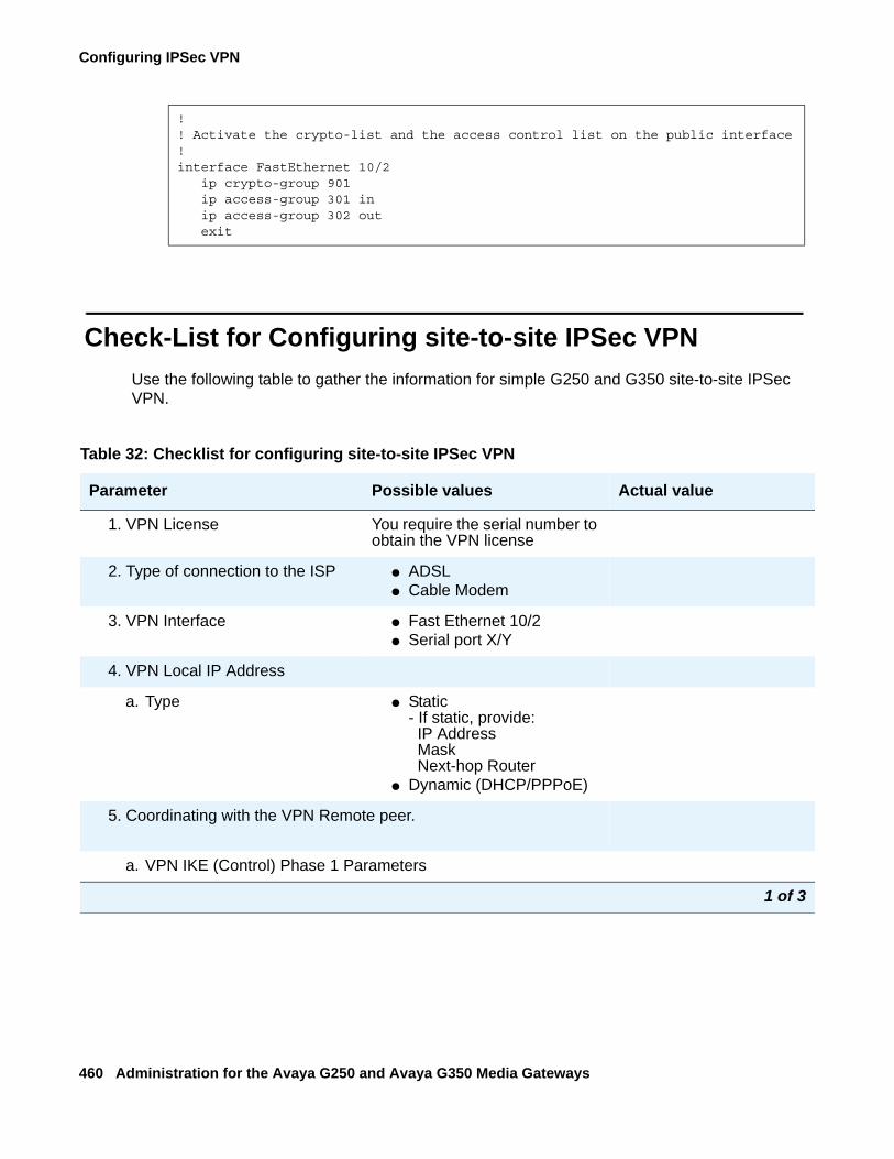
Configuring IPSec VPN
460 Administration for the Avaya G250 and Avaya G350 Media Gateways
Check-List for Configuring site-to-site IPSec VPNUse the following table to gather the information for simple G250 and G350 site-to-site IPSec VPN.
!! Activate the crypto-list and the access control list on the public interface!interface FastEthernet 10/2 ip crypto-group 901 ip access-group 301 in ip access-group 302 out exit
Table 32: Checklist for configuring site-to-site IPSec VPN
Parameter Possible values Actual value
1. VPN License You require the serial number to obtain the VPN license
2. Type of connection to the ISP ● ADSL ● Cable Modem
3. VPN Interface ● Fast Ethernet 10/2● Serial port X/Y
4. VPN Local IP Address
a. Type ● Static - If static, provide:
IP Address Mask Next-hop Router
● Dynamic (DHCP/PPPoE)
5. Coordinating with the VPN Remote peer.
a. VPN IKE (Control) Phase 1 Parameters
1 of 3
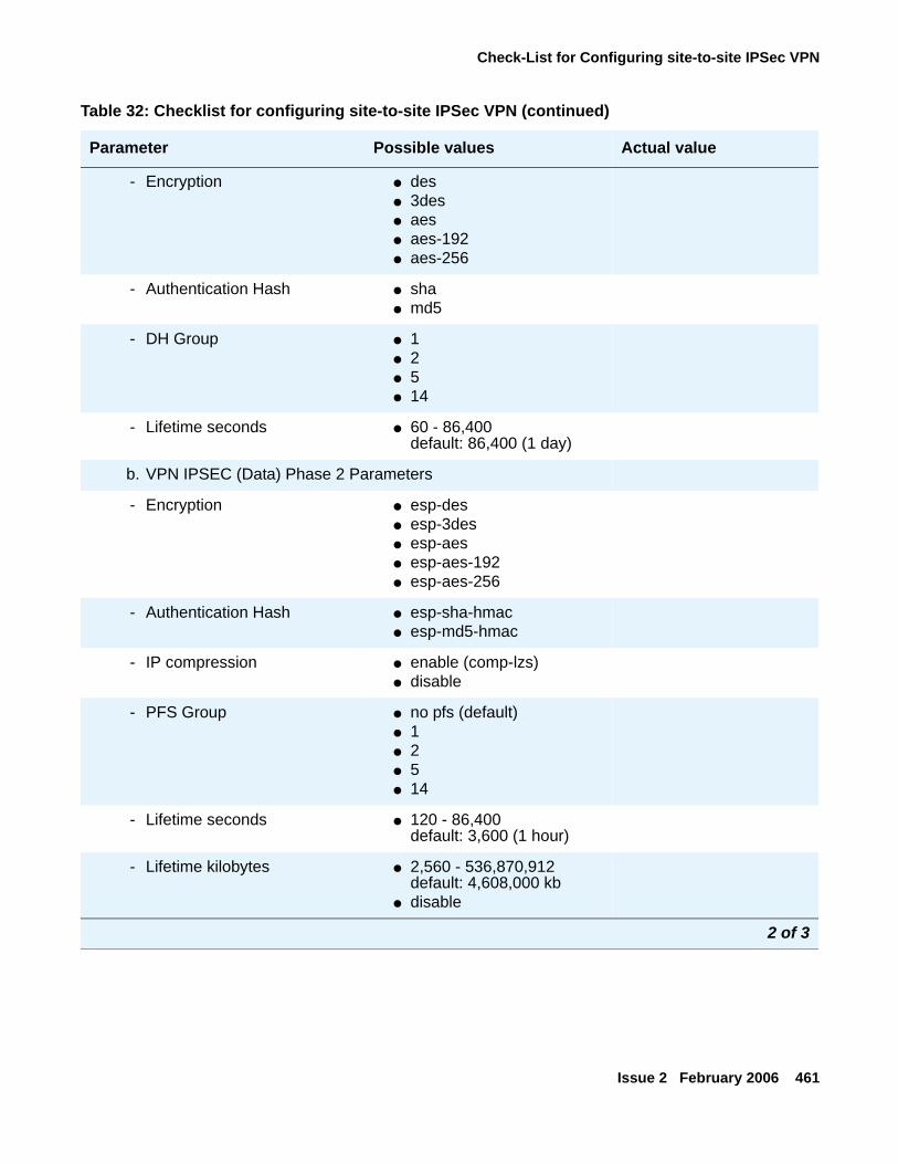
Check-List for Configuring site-to-site IPSec VPN
Issue 2 February 2006 461
- Encryption ● des● 3des● aes● aes-192● aes-256
- Authentication Hash ● sha● md5
- DH Group ● 1● 2● 5● 14
- Lifetime seconds ● 60 - 86,400default: 86,400 (1 day)
b. VPN IPSEC (Data) Phase 2 Parameters
- Encryption ● esp-des● esp-3des● esp-aes● esp-aes-192● esp-aes-256
- Authentication Hash ● esp-sha-hmac● esp-md5-hmac
- IP compression ● enable (comp-lzs)● disable
- PFS Group ● no pfs (default)● 1● 2● 5● 14
- Lifetime seconds ● 120 - 86,400default: 3,600 (1 hour)
- Lifetime kilobytes ● 2,560 - 536,870,912default: 4,608,000 kb
● disable
Table 32: Checklist for configuring site-to-site IPSec VPN (continued)
Parameter Possible values Actual value
2 of 3
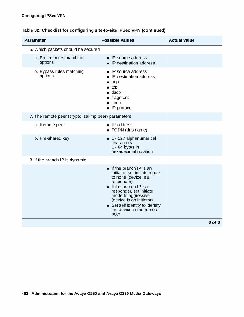
Configuring IPSec VPN
462 Administration for the Avaya G250 and Avaya G350 Media Gateways
6. Which packets should be secured
a. Protect rules matching options
● IP source address● IP destination address
b. Bypass rules matching options
● IP source address● IP destination address● udp● tcp● dscp● fragment● icmp● IP protocol
7. The remote peer (crypto isakmp peer) parameters
a. Remote peer ● IP address● FQDN (dns name)
b. Pre-shared key ● 1 - 127 alphanumerical characters. 1 - 64 bytes in hexadecimal notation
8. If the branch IP is dynamic
● If the branch IP is an initiator, set initiate mode to none (device is a responder)
● If the branch IP is a responder, set initiate mode to aggressive (device is an initiator)
● Set self identity to identify the device in the remote peer
Table 32: Checklist for configuring site-to-site IPSec VPN (continued)
Parameter Possible values Actual value
3 of 3
Issue 2 February 2006 463
Chapter 20: Configuring policy
This chapter provides information about configuring QoS policy on the G250/G350 and contains the following sections:
● Policy overview — an overview of QoS policy configuration
● Defining policy lists — instructions on how to configure policy lists
● Attaching policy lists to an interface — instructions on how to attach a policy list to an interface
● Device-wide policy lists — instructions on how to attach a policy list to all interfaces
● Defining global rules — instructions on how to configure rules that are executed before the list is evaluated
● Defining rules — instructions on how to configure rules, including an overview of rule criteria
● Composite operations — a description of composite operations and instructions on how to configure composite operations
● DSCP table — a description of the DSCP table, with examples
● Displaying and testing policy lists — instructions on how to view the configuration of policy lists and test their effects on simulated IP packets
Policy overviewPolicy lists allow you to control the ingress and egress of traffic to a router or port. You can use policies to manage security, determine packet priority through an interface, implement quality of service, or determine routing for a specific application or user. Each policy list consists of a set of rules determining the behavior of a packet entering or leaving the interface on which the list is applied.
This section provides an overview of policy lists on the G250/G350 and includes the following topics:
● Access control lists — a description of access control lists, which control which packets are authorized to pass through an interface
● QoS lists — a description of QoS lists, which can change the value of the QoS field in a packet
● Policy-based routing — an overview of policy-based routing, which is described in more detail in Configuring policy-based routing on page 487
● Managing policy lists — an overview of how to manage policy lists on the G250/G350
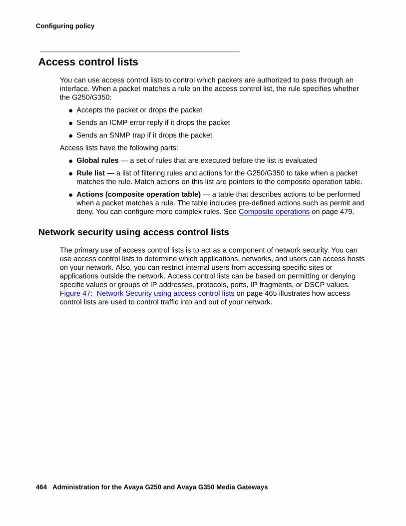
Configuring policy
464 Administration for the Avaya G250 and Avaya G350 Media Gateways
Access control listsYou can use access control lists to control which packets are authorized to pass through an interface. When a packet matches a rule on the access control list, the rule specifies whether the G250/G350:
● Accepts the packet or drops the packet
● Sends an ICMP error reply if it drops the packet
● Sends an SNMP trap if it drops the packet
Access lists have the following parts:
● Global rules — a set of rules that are executed before the list is evaluated
● Rule list — a list of filtering rules and actions for the G250/G350 to take when a packet matches the rule. Match actions on this list are pointers to the composite operation table.
● Actions (composite operation table) — a table that describes actions to be performed when a packet matches a rule. The table includes pre-defined actions such as permit and deny. You can configure more complex rules. See Composite operations on page 479.
Network security using access control lists
The primary use of access control lists is to act as a component of network security. You can use access control lists to determine which applications, networks, and users can access hosts on your network. Also, you can restrict internal users from accessing specific sites or applications outside the network. Access control lists can be based on permitting or denying specific values or groups of IP addresses, protocols, ports, IP fragments, or DSCP values. Figure 47: Network Security using access control lists on page 465 illustrates how access control lists are used to control traffic into and out of your network.
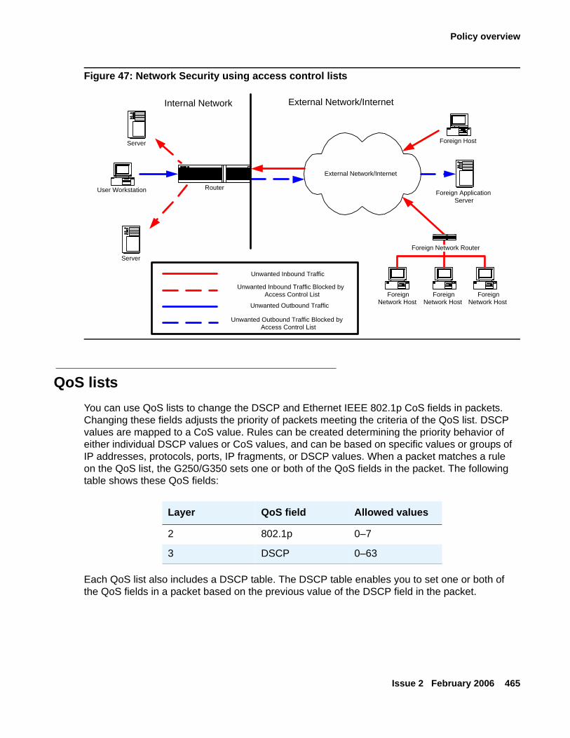
Policy overview
Issue 2 February 2006 465
Figure 47: Network Security using access control lists
QoS listsYou can use QoS lists to change the DSCP and Ethernet IEEE 802.1p CoS fields in packets. Changing these fields adjusts the priority of packets meeting the criteria of the QoS list. DSCP values are mapped to a CoS value. Rules can be created determining the priority behavior of either individual DSCP values or CoS values, and can be based on specific values or groups of IP addresses, protocols, ports, IP fragments, or DSCP values. When a packet matches a rule on the QoS list, the G250/G350 sets one or both of the QoS fields in the packet. The following table shows these QoS fields:
Each QoS list also includes a DSCP table. The DSCP table enables you to set one or both of the QoS fields in a packet based on the previous value of the DSCP field in the packet.
Foreign Network Router
Foreign ApplicationServer
Server
Server
User Workstation
External Network/Internet
Router
Foreign Host
Unwanted Inbound Traffic
Unwanted Inbound Traffic Blocked byAccess Control List
Unwanted Outbound Traffic Blocked byAccess Control List
Unwanted Outbound Traffic
Internal Network External Network/Internet
ForeignNetwork Host
ForeignNetwork Host
ForeignNetwork Host
Layer QoS field Allowed values
2 802.1p 0–7
3 DSCP 0–63
Configuring policy
466 Administration for the Avaya G250 and Avaya G350 Media Gateways
QoS lists have the following parts:
● Rule list — a list of filtering rules and actions for the G250/G350 to take when a packet matches the rule. Match actions on this list are pointers to the composite operation table.
● Actions (composite operation table) — a table that describes actions to be performed when a packet matches a rule. The table includes pre-defined actions such as permit and deny. You can configure more complex rules. Refer to Composite operations on page 479.
● DSCP map — a table that contains DSCP code points and match action pairs. Match actions are pointers to the composite operation table. Refer to DSCP table on page 482.
Policy-based routingYou can use policy-based routing to determine the routing path a packet takes based on the type of packet or the packet’s source or destination IP addresses or DSCP field. This enables you to route different types of traffic over different routes or interfaces. For example, you use policy-based routing to route voice traffic over a WAN interface and data traffic over the Internet. Policy-based routing is implemented by means of policy-based routing (PBR) lists. PBR lists are similar in many respects to access control lists and QoS lists. However, since there are also some key differences, policy-based routing is explained in a separate chapter. Refer to Configuring policy-based routing on page 487.
Managing policy listsYou can manage policy lists on the Avaya G250/G350 Media Gateway with CLI commands. You can also manage policy lists throughout your network with Avaya QoS Manager. Avaya QoS Manager is part of Avaya Integrated Management. Figure 48: Policy lists on page 467 illustrates the operation of policy lists on the Avaya G250/G350 Media Gateway:
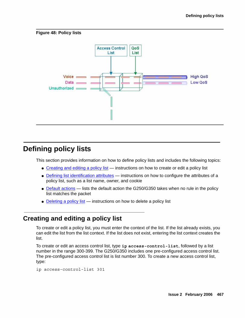
Defining policy lists
Issue 2 February 2006 467
Figure 48: Policy lists
Defining policy listsThis section provides information on how to define policy lists and includes the following topics:
● Creating and editing a policy list — instructions on how to create or edit a policy list
● Defining list identification attributes — instructions on how to configure the attributes of a policy list, such as a list name, owner, and cookie
● Default actions — lists the default action the G250/G350 takes when no rule in the policy list matches the packet
● Deleting a policy list — instructions on how to delete a policy list
Creating and editing a policy listTo create or edit a policy list, you must enter the context of the list. If the list already exists, you can edit the list from the list context. If the list does not exist, entering the list context creates the list.
To create or edit an access control list, type ip access-control-list, followed by a list number in the range 300-399. The G250/G350 includes one pre-configured access control list. The pre-configured access control list is list number 300. To create a new access control list, type:
ip access-control-list 301
Configuring policy
468 Administration for the Avaya G250 and Avaya G350 Media Gateways
To create or edit a QoS list, type ip qos-list, followed by a list number in the range 400-499. The G250/G350 includes one pre-configured QoS list. The pre-configured QoS list is list number 400. To create a new QoS list, type:
ip qos-list 401
Once you have entered the list context, you can perform the following actions:
● Configure rules — see Defining rules on page 472
● Configure composite operations — see Composite operations on page 479
● Configure DSCP mapping (QoS lists only) — see DSCP table on page 482
Defining list identification attributesThe following policy list attributes are used by Avaya QoS Manager software to identify policy lists:
● Name
● Owner
● Cookie
To define these attributes:
1. Enter the context of the policy list in which you want to define the attribute.
2. Enter one of the following commands, followed by a text string or integer:
- name — defines a list name (text string). The default value is owner.
- owner — defines a list owner (text string). The default value is list#<listnumber>.
- cookie — defines a list cookie (integer). The Avaya QoS Manager uses the cookie attribute internally. Normally, you should not change this attribute.
To set a policy list attribute to its default setting, use the no form of the appropriate command. For example, to set a list to its default name, use the command no name.
To view the attributes, use the show list command in the context of the list.
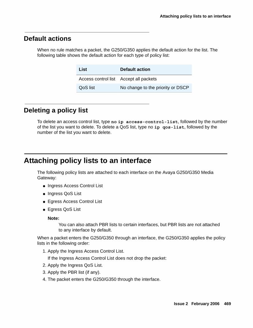
Attaching policy lists to an interface
Issue 2 February 2006 469
Default actionsWhen no rule matches a packet, the G250/G350 applies the default action for the list. The following table shows the default action for each type of policy list:
Deleting a policy listTo delete an access control list, type no ip access-control-list, followed by the number of the list you want to delete. To delete a QoS list, type no ip qos-list, followed by the number of the list you want to delete.
Attaching policy lists to an interfaceThe following policy lists are attached to each interface on the Avaya G250/G350 Media Gateway:
● Ingress Access Control List
● Ingress QoS List
● Egress Access Control List
● Egress QoS List
Note:Note: You can also attach PBR lists to certain interfaces, but PBR lists are not attached
to any interface by default.
When a packet enters the G250/G350 through an interface, the G250/G350 applies the policy lists in the following order:
1. Apply the Ingress Access Control List.If the Ingress Access Control List does not drop the packet:
2. Apply the Ingress QoS List.3. Apply the PBR list (if any).4. The packet enters the G250/G350 through the interface.
List Default action
Access control list Accept all packets
QoS list No change to the priority or DSCP
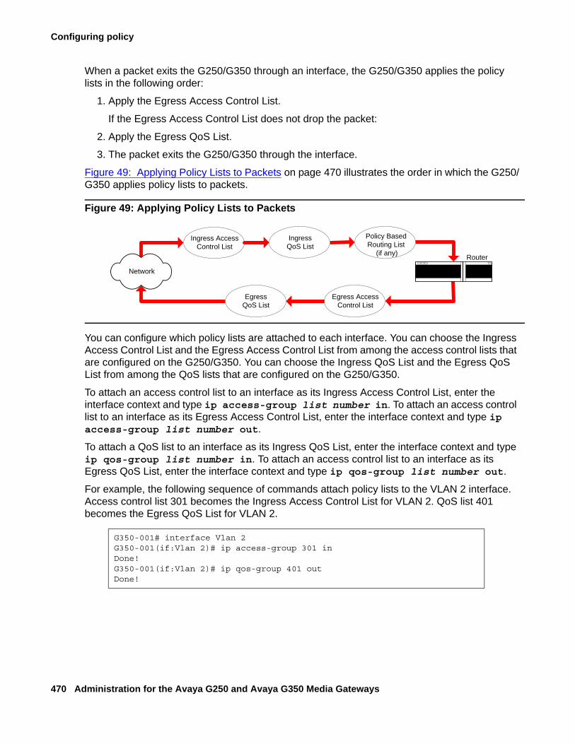
Configuring policy
470 Administration for the Avaya G250 and Avaya G350 Media Gateways
When a packet exits the G250/G350 through an interface, the G250/G350 applies the policy lists in the following order:
1. Apply the Egress Access Control List.
If the Egress Access Control List does not drop the packet:
2. Apply the Egress QoS List.
3. The packet exits the G250/G350 through the interface.
Figure 49: Applying Policy Lists to Packets on page 470 illustrates the order in which the G250/G350 applies policy lists to packets.
Figure 49: Applying Policy Lists to Packets
You can configure which policy lists are attached to each interface. You can choose the Ingress Access Control List and the Egress Access Control List from among the access control lists that are configured on the G250/G350. You can choose the Ingress QoS List and the Egress QoS List from among the QoS lists that are configured on the G250/G350.
To attach an access control list to an interface as its Ingress Access Control List, enter the interface context and type ip access-group list number in. To attach an access control list to an interface as its Egress Access Control List, enter the interface context and type ip access-group list number out.
To attach a QoS list to an interface as its Ingress QoS List, enter the interface context and type ip qos-group list number in. To attach an access control list to an interface as its Egress QoS List, enter the interface context and type ip qos-group list number out.
For example, the following sequence of commands attach policy lists to the VLAN 2 interface. Access control list 301 becomes the Ingress Access Control List for VLAN 2. QoS list 401 becomes the Egress QoS List for VLAN 2.
G350-001# interface Vlan 2G350-001(if:Vlan 2)# ip access-group 301 inDone!G350-001(if:Vlan 2)# ip qos-group 401 outDone!
Policy BasedRouting List
(if any) Router
IngressQoS List
Ingress AccessControl List
Egress AccessControl List
Network
EgressQoS List
Device-wide policy lists
Issue 2 February 2006 471
To remove a list from an interface, use the no form of the appropriate command. For example, if the Ingress Access Control List for the VLAN 1 interface is list number 302, you can remove the list from the interface by typing the following commands:
Note:Note: You cannot change or delete a default list. You cannot change or delete any list
when it is attached to an interface. In order to change or delete a list that is attached to an interface, you must first remove the list from the interface. You can then change or delete the list. After changing the list, you can reattach the list to the interface.
Device-wide policy listsYou can attach a policy list (other than a policy-based routing list) to every interface on the G250/G350 using one command. To do this, attach a list to the Loopback 1 interface. For more information, see Attaching policy lists to an interface on page 469.
Note:Note: If you attach a policy list to a Loopback interface other than Loopback 1, the
policy list has no effect.
When you attach a policy list to the Loopback 1 interface, thereby creating a device-wide policy list, and you also attach policy lists to specific interfaces, the G250/G350 applies the lists in the following order:
● Incoming packets:
a. Apply the ingress policy lists that are attached to the interface.
b. Apply the device-wide ingress policy lists.
● Outgoing packets:
a. Apply the device-wide egress policy lists.
b. Apply the egress policy lists that are attached to the interface.
G350-001(super)# interface Vlan 1G350-001(super-if:Vlan 1)# no ip access-group inDone!
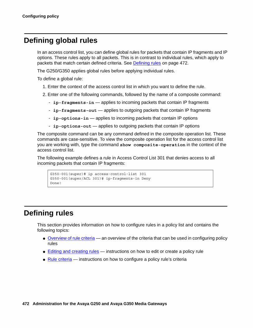
Configuring policy
472 Administration for the Avaya G250 and Avaya G350 Media Gateways
Defining global rulesIn an access control list, you can define global rules for packets that contain IP fragments and IP options. These rules apply to all packets. This is in contrast to individual rules, which apply to packets that match certain defined criteria. See Defining rules on page 472.
The G250/G350 applies global rules before applying individual rules.
To define a global rule:
1. Enter the context of the access control list in which you want to define the rule.
2. Enter one of the following commands, followed by the name of a composite command:
- ip-fragments-in — applies to incoming packets that contain IP fragments
- ip-fragments-out — applies to outgoing packets that contain IP fragments
- ip-options-in — applies to incoming packets that contain IP options
- ip-options-out — applies to outgoing packets that contain IP options
The composite command can be any command defined in the composite operation list. These commands are case-sensitive. To view the composite operation list for the access control list you are working with, type the command show composite-operation in the context of the access control list.
The following example defines a rule in Access Control List 301 that denies access to all incoming packets that contain IP fragments:
Defining rulesThis section provides information on how to configure rules in a policy list and contains the following topics:
● Overview of rule criteria — an overview of the criteria that can be used in configuring policy rules
● Editing and creating rules — instructions on how to edit or create a policy rule
● Rule criteria — instructions on how to configure a policy rule’s criteria
G350-001(super)# ip access-control-list 301G350-001(super/ACL 301)# ip-fragments-in DenyDone!
Defining rules
Issue 2 February 2006 473
Overview of rule criteriaYou can configure policy rules to match packets based on one or more of the following criteria:
● Source IP address, or a range of addresses
● Destination IP address or a range of addresses
● IP protocol, such as TCP, UDP, ICMP, IGMP
● Source TCP or UDP port or a range of ports
● Destination TCP or UDP port or a range of ports
● ICMP type and code
● Fragment
● DSCP
Use IP wildcards to specify a range of source or destination IP addresses. The zero bits in the wildcard correspond to bits in the IP address that remain fixed. The one bits in the wildcard correspond to bits in the IP address that can vary. Note that this is the opposite of how bits are used in a subnet mask.
For access control lists, you can require the packet to be part of an established TCP session. If the packet is a request for a new TCP session, the packet does not match the rule. You can also specify whether an access control list accepts packets that have an IP option field.
Editing and creating rulesTo create or edit a policy rule, you must enter the context of the rule. If the rule already exists, you can edit the rule from the rule context. If the rule does not exist, entering the rule context creates the rule.
To enter a rule context:
1. Enter the context of the list in which you want to create or edit a rule.
2. Type the command ip-rule, followed by the number of the rule you want to create or edit. For example, to create rule 1, type ip-rule 1.
You can use the description command in the rule context to add a description of the rule. This description is used in the AccessViolation Policy trap to identify and describe the IP rule in which the trap was caused.
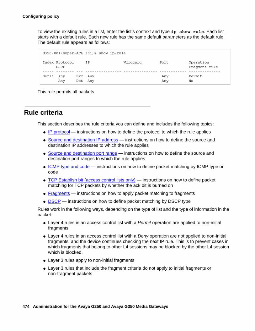
Configuring policy
474 Administration for the Avaya G250 and Avaya G350 Media Gateways
To view the existing rules in a list, enter the list’s context and type ip show-rule. Each list starts with a default rule. Each new rule has the same default parameters as the default rule. The default rule appears as follows:
This rule permits all packets.
Rule criteriaThis section describes the rule criteria you can define and includes the following topics:
● IP protocol — instructions on how to define the protocol to which the rule applies
● Source and destination IP address — instructions on how to define the source and destination IP addresses to which the rule applies
● Source and destination port range — instructions on how to define the source and destination port ranges to which the rule applies
● ICMP type and code — instructions on how to define packet matching by ICMP type or code
● TCP Establish bit (access control lists only) — instructions on how to define packet matching for TCP packets by whether the ack bit is burned on
● Fragments — instructions on how to apply packet matching to fragments
● DSCP — instructions on how to define packet matching by DSCP type
Rules work in the following ways, depending on the type of list and the type of information in the packet:
● Layer 4 rules in an access control list with a Permit operation are applied to non-initial fragments
● Layer 4 rules in an access control list with a Deny operation are not applied to non-initial fragments, and the device continues checking the next IP rule. This is to prevent cases in which fragments that belong to other L4 sessions may be blocked by the other L4 session which is blocked.
● Layer 3 rules apply to non-initial fragments
● Layer 3 rules that include the fragment criteria do not apply to initial fragments or non-fragment packets
G350-001(super-ACL 301)# show ip-rule
Index Protocol IP Wildcard Port Operation DSCP Fragment rule----- -------- --- ---------------- --------------- ------------ --------------Deflt Any Src Any Any Permit Any Dst Any Any No

Defining rules
Issue 2 February 2006 475
● Layer 3 rules that do not include the fragment criteria apply to initial fragments and non-fragment packets
● Layer 4 rules apply to initial fragments and non-fragment packets
● Layer 3 and Layer 4 rules in QoS and policy-based routing lists apply to non-initial fragments
IP protocol
To specify the IP protocol to which the rule applies, use the ip-protocol command, followed by the name of an IP protocol. If you want the rule to apply to all protocol, use any with the command. If you want the rule to apply to all protocols except for one, use the no form of the command, followed by the name of the protocol to which you do not want the rule to apply.
The following command specifies the UDP protocol for rule 1 in QoS list 401:
The following command specifies any IP protocol except IGMP for rule 3 in access control list 302:
Source and destination IP address
To specify a range of source and destination IP addresses to which the rule applies, use the commands source-ip and destination-ip, followed by the IP range criteria. The IP range criteria can be any of the following:
● a range — type two IP addresses to set a range of IP addresses to which the rule applies
● a single address — type host, followed by an IP address, to set a single IP address to which the rule applies.
● wildcard — type host, followed by an IP address using wildcards, to set a range of IP addresses to which the rule applies
● any — type any to apply the rule to all IP addresses
Use the no form of the appropriate command to specify that the rule does not apply to the IP address or addresses defined by the command.
The following command specifies a source IP address of 10.10.10.20 for rule 1 in access control list 301:
G350-001(QoS 401/rule 1)# ip-protocol udp
G350-001(ACL 302/ip rule 3)# no ip-protocol igmp
G350-001(ACL 301/ip rule 1)# source-ip host 10.10.10.20
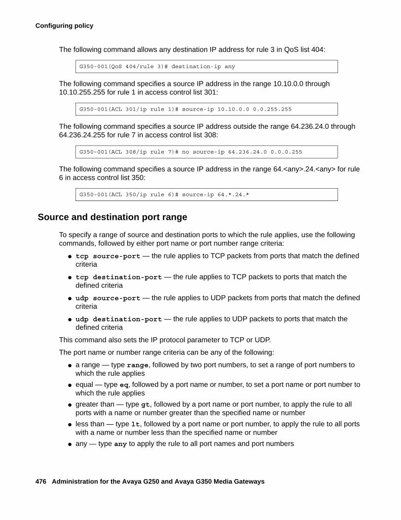
Configuring policy
476 Administration for the Avaya G250 and Avaya G350 Media Gateways
The following command allows any destination IP address for rule 3 in QoS list 404:
The following command specifies a source IP address in the range 10.10.0.0 through 10.10.255.255 for rule 1 in access control list 301:
The following command specifies a source IP address outside the range 64.236.24.0 through 64.236.24.255 for rule 7 in access control list 308:
The following command specifies a source IP address in the range 64.<any>.24.<any> for rule 6 in access control list 350:
Source and destination port range
To specify a range of source and destination ports to which the rule applies, use the following commands, followed by either port name or port number range criteria:
● tcp source-port — the rule applies to TCP packets from ports that match the defined criteria
● tcp destination-port — the rule applies to TCP packets to ports that match the defined criteria
● udp source-port — the rule applies to UDP packets from ports that match the defined criteria
● udp destination-port — the rule applies to UDP packets to ports that match the defined criteria
This command also sets the IP protocol parameter to TCP or UDP.
The port name or number range criteria can be any of the following:
● a range — type range, followed by two port numbers, to set a range of port numbers to which the rule applies
● equal — type eq, followed by a port name or number, to set a port name or port number to which the rule applies
● greater than — type gt, followed by a port name or port number, to apply the rule to all ports with a name or number greater than the specified name or number
● less than — type lt, followed by a port name or port number, to apply the rule to all ports with a name or number less than the specified name or number
● any — type any to apply the rule to all port names and port numbers
G350-001(QoS 404/rule 3)# destination-ip any
G350-001(ACL 301/ip rule 1)# source-ip 10.10.0.0 0.0.255.255
G350-001(ACL 308/ip rule 7)# no source-ip 64.236.24.0 0.0.0.255
G350-001(ACL 350/ip rule 6)# source-ip 64.*.24.*
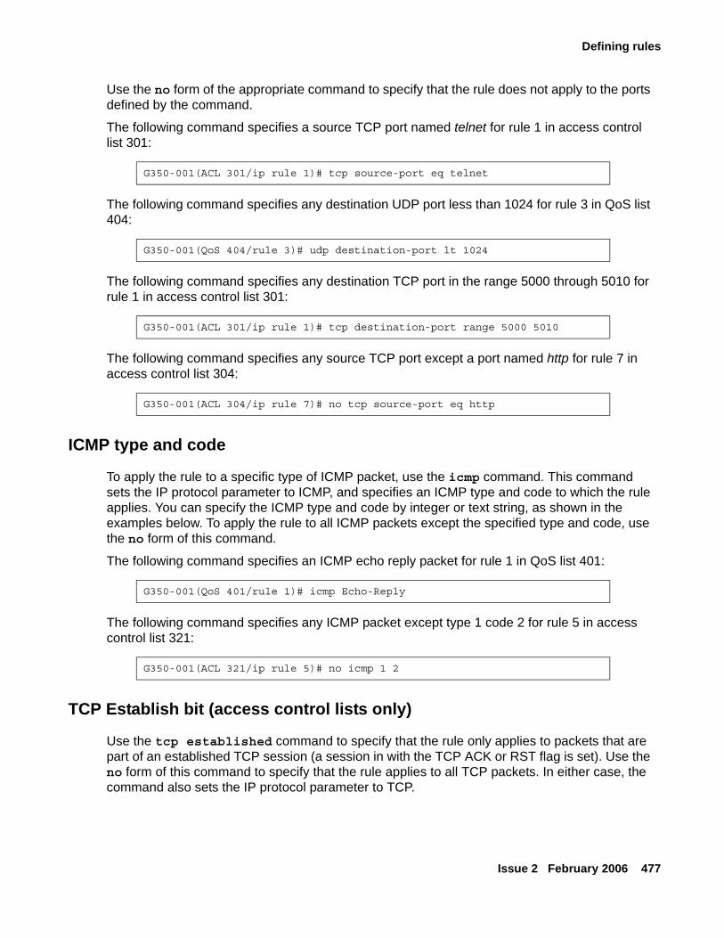
Defining rules
Issue 2 February 2006 477
Use the no form of the appropriate command to specify that the rule does not apply to the ports defined by the command.
The following command specifies a source TCP port named telnet for rule 1 in access control list 301:
The following command specifies any destination UDP port less than 1024 for rule 3 in QoS list 404:
The following command specifies any destination TCP port in the range 5000 through 5010 for rule 1 in access control list 301:
The following command specifies any source TCP port except a port named http for rule 7 in access control list 304:
ICMP type and code
To apply the rule to a specific type of ICMP packet, use the icmp command. This command sets the IP protocol parameter to ICMP, and specifies an ICMP type and code to which the rule applies. You can specify the ICMP type and code by integer or text string, as shown in the examples below. To apply the rule to all ICMP packets except the specified type and code, use the no form of this command.
The following command specifies an ICMP echo reply packet for rule 1 in QoS list 401:
The following command specifies any ICMP packet except type 1 code 2 for rule 5 in access control list 321:
TCP Establish bit (access control lists only)
Use the tcp established command to specify that the rule only applies to packets that are part of an established TCP session (a session in with the TCP ACK or RST flag is set). Use the no form of this command to specify that the rule applies to all TCP packets. In either case, the command also sets the IP protocol parameter to TCP.
G350-001(ACL 301/ip rule 1)# tcp source-port eq telnet
G350-001(QoS 404/rule 3)# udp destination-port lt 1024
G350-001(ACL 301/ip rule 1)# tcp destination-port range 5000 5010
G350-001(ACL 304/ip rule 7)# no tcp source-port eq http
G350-001(QoS 401/rule 1)# icmp Echo-Reply
G350-001(ACL 321/ip rule 5)# no icmp 1 2
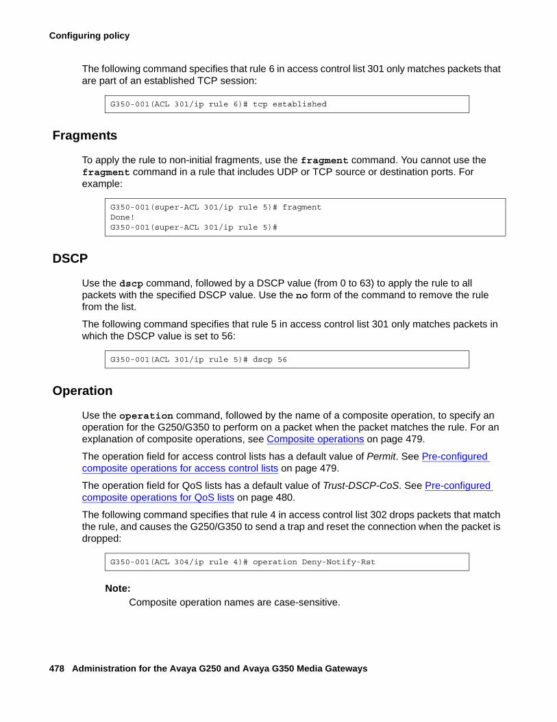
Configuring policy
478 Administration for the Avaya G250 and Avaya G350 Media Gateways
The following command specifies that rule 6 in access control list 301 only matches packets that are part of an established TCP session:
Fragments
To apply the rule to non-initial fragments, use the fragment command. You cannot use the fragment command in a rule that includes UDP or TCP source or destination ports. For example:
DSCP
Use the dscp command, followed by a DSCP value (from 0 to 63) to apply the rule to all packets with the specified DSCP value. Use the no form of the command to remove the rule from the list.
The following command specifies that rule 5 in access control list 301 only matches packets in which the DSCP value is set to 56:
Operation
Use the operation command, followed by the name of a composite operation, to specify an operation for the G250/G350 to perform on a packet when the packet matches the rule. For an explanation of composite operations, see Composite operations on page 479.
The operation field for access control lists has a default value of Permit. See Pre-configured composite operations for access control lists on page 479.
The operation field for QoS lists has a default value of Trust-DSCP-CoS. See Pre-configured composite operations for QoS lists on page 480.
The following command specifies that rule 4 in access control list 302 drops packets that match the rule, and causes the G250/G350 to send a trap and reset the connection when the packet is dropped:
Note:Note: Composite operation names are case-sensitive.
G350-001(ACL 301/ip rule 6)# tcp established
G350-001(super-ACL 301/ip rule 5)# fragmentDone!G350-001(super-ACL 301/ip rule 5)#
G350-001(ACL 301/ip rule 5)# dscp 56
G350-001(ACL 304/ip rule 4)# operation Deny-Notify-Rst
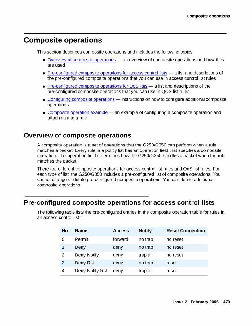
Composite operations
Issue 2 February 2006 479
Composite operationsThis section describes composite operations and includes the following topics:
● Overview of composite operations — an overview of composite operations and how they are used
● Pre-configured composite operations for access control lists — a list and descriptions of the pre-configured composite operations that you can use in access control list rules
● Pre-configured composite operations for QoS lists — a list and descriptions of the pre-configured composite operations that you can use in QOS list rules
● Configuring composite operations — instructions on how to configure additional composite operations
● Composite operation example — an example of configuring a composite operation and attaching it to a rule
Overview of composite operationsA composite operation is a set of operations that the G250/G350 can perform when a rule matches a packet. Every rule in a policy list has an operation field that specifies a composite operation. The operation field determines how the G250/G350 handles a packet when the rule matches the packet.
There are different composite operations for access control list rules and QoS list rules. For each type of list, the G250/G350 includes a pre-configured list of composite operations. You cannot change or delete pre-configured composite operations. You can define additional composite operations.
Pre-configured composite operations for access control listsThe following table lists the pre-configured entries in the composite operation table for rules in an access control list:
No Name Access Notify Reset Connection
0 Permit forward no trap no reset
1 Deny deny no trap no reset
2 Deny-Notify deny trap all no reset
3 Deny-Rst deny no trap reset
4 Deny-Notify-Rst deny trap all reset
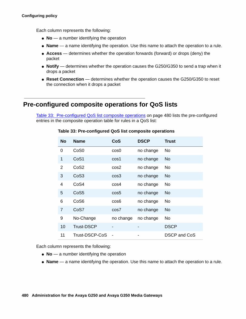
Configuring policy
480 Administration for the Avaya G250 and Avaya G350 Media Gateways
Each column represents the following:
● No — a number identifying the operation
● Name — a name identifying the operation. Use this name to attach the operation to a rule.
● Access — determines whether the operation forwards (forward) or drops (deny) the packet
● Notify — determines whether the operation causes the G250/G350 to send a trap when it drops a packet
● Reset Connection — determines whether the operation causes the G250/G350 to reset the connection when it drops a packet
Pre-configured composite operations for QoS listsTable 33: Pre-configured QoS list composite operations on page 480 lists the pre-configured entries in the composite operation table for rules in a QoS list:
Each column represents the following:
● No — a number identifying the operation
● Name — a name identifying the operation. Use this name to attach the operation to a rule.
Table 33: Pre-configured QoS list composite operations
No Name CoS DSCP Trust
0 CoS0 cos0 no change No
1 CoS1 cos1 no change No
2 CoS2 cos2 no change No
3 CoS3 cos3 no change No
4 CoS4 cos4 no change No
5 CoS5 cos5 no change No
6 CoS6 cos6 no change No
7 CoS7 cos7 no change No
9 No-Change no change no change No
10 Trust-DSCP - - DSCP
11 Trust-DSCP-CoS - - DSCP and CoS
Composite operations
Issue 2 February 2006 481
● CoS — the operation sets the Ethernet IEEE 802.1p CoS field in the packet to the value listed in this column
● DSCP — the operation sets the DSCP field in the packet to the value listed in this column
● Trust — determines how to treat packets that have been tagged by the originator or other network devices. If the composite operation is set to Trust-DSCP, the packet’s CoS tag is set to 0 before the QoS list rules and DSCP map are executed. If the composite operation is set to CoSX, the DSCP map is ignored, but the QoS list rules are executed on the Ethernet IEEE 802.1p CoS field. (For example, the composite operation CoS3 changes the CoS field to 3). If the composite operation is set to Trust-DSCP-CoS, the operation uses the great of the CoS or the DSCP value. If the composite operation is set to No Change, the operation makes no change to the packet’s QoS tags.
Configuring composite operationsYou can configure additional composite operations for QoS lists. You can also edit composite operations that you configured. You cannot edit pre-configured composite operations.
Note:Note: You cannot configure additional composite operations for access control lists,
since all possible composite operations are pre-configured.
To create or edit a composite operation:
1. Enter the context of a QoS list.
2. Type the composite-operation command, followed by an index number. The number must be 12 or higher, since numbers 1 through 11 are assigned to pre-configured lists.
3. Use one or more of the following commands to set the parameters of the composite operation:
- dscp — determines the value to which the rule resets the packet’s DSCP field. To ignore the DSCP field, use the argument no change, or use the command no dscp.
- cos — determines the value to which the rule resets the packet’s CoS field. To ignore the CoS field, use the argument no change, or use the command no cos.
4. Use the name command, followed by a text string, to assign a name to the composite operation. You must assign a name to the composite operation, because when you attach the composite operation to a rule, you use the name, not the index number, to identify the composite operation.
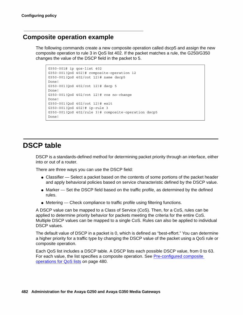
Configuring policy
482 Administration for the Avaya G250 and Avaya G350 Media Gateways
Composite operation exampleThe following commands create a new composite operation called dscp5 and assign the new composite operation to rule 3 in QoS list 402. If the packet matches a rule, the G250/G350 changes the value of the DSCP field in the packet to 5.
DSCP tableDSCP is a standards-defined method for determining packet priority through an interface, either into or out of a router.
There are three ways you can use the DSCP field:
● Classifier — Select a packet based on the contents of some portions of the packet header and apply behavioral policies based on service characteristic defined by the DSCP value.
● Marker — Set the DSCP field based on the traffic profile, as determined by the defined rules.
● Metering — Check compliance to traffic profile using filtering functions.
A DSCP value can be mapped to a Class of Service (CoS). Then, for a CoS, rules can be applied to determine priority behavior for packets meeting the criteria for the entire CoS. Multiple DSCP values can be mapped to a single CoS. Rules can also be applied to individual DSCP values.
The default value of DSCP in a packet is 0, which is defined as “best-effort.” You can determine a higher priority for a traffic type by changing the DSCP value of the packet using a QoS rule or composite operation.
Each QoS list includes a DSCP table. A DSCP lists each possible DSCP value, from 0 to 63. For each value, the list specifies a composite operation. See Pre-configured composite operations for QoS lists on page 480.
G350-001# ip qos-list 402G350-001(QoS 402)# composite-operation 12G350-001(QoS 402/cot 12)# name dscp5Done!G350-001(QoS 402/cot 12)# dscp 5Done!G350-001(QoS 402/cot 12)# cos no-changeDone!G350-001(QoS 402/cot 12)# exitG350-001(QoS 402)# ip-rule 3G350-001(QoS 402/rule 3)# composite-operation dscp5Done!
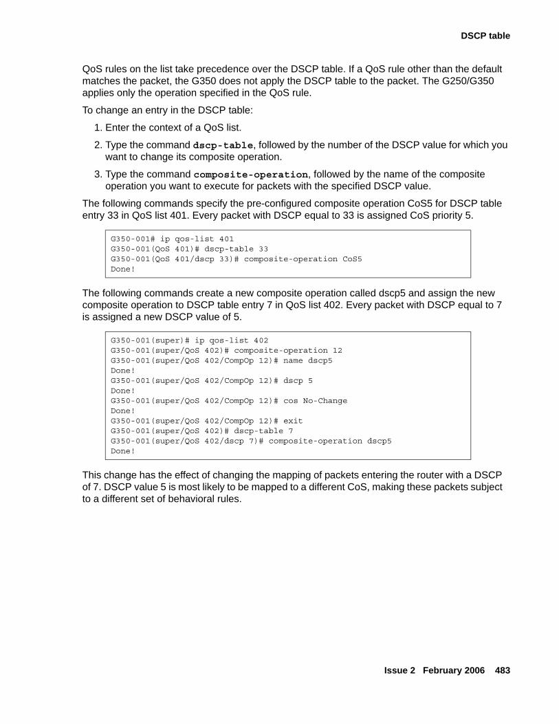
DSCP table
Issue 2 February 2006 483
QoS rules on the list take precedence over the DSCP table. If a QoS rule other than the default matches the packet, the G350 does not apply the DSCP table to the packet. The G250/G350 applies only the operation specified in the QoS rule.
To change an entry in the DSCP table:
1. Enter the context of a QoS list.
2. Type the command dscp-table, followed by the number of the DSCP value for which you want to change its composite operation.
3. Type the command composite-operation, followed by the name of the composite operation you want to execute for packets with the specified DSCP value.
The following commands specify the pre-configured composite operation CoS5 for DSCP table entry 33 in QoS list 401. Every packet with DSCP equal to 33 is assigned CoS priority 5.
The following commands create a new composite operation called dscp5 and assign the new composite operation to DSCP table entry 7 in QoS list 402. Every packet with DSCP equal to 7 is assigned a new DSCP value of 5.
This change has the effect of changing the mapping of packets entering the router with a DSCP of 7. DSCP value 5 is most likely to be mapped to a different CoS, making these packets subject to a different set of behavioral rules.
G350-001# ip qos-list 401G350-001(QoS 401)# dscp-table 33G350-001(QoS 401/dscp 33)# composite-operation CoS5Done!
G350-001(super)# ip qos-list 402G350-001(super/QoS 402)# composite-operation 12G350-001(super/QoS 402/CompOp 12)# name dscp5Done!G350-001(super/QoS 402/CompOp 12)# dscp 5Done!G350-001(super/QoS 402/CompOp 12)# cos No-ChangeDone!G350-001(super/QoS 402/CompOp 12)# exitG350-001(super/QoS 402)# dscp-table 7G350-001(super/QoS 402/dscp 7)# composite-operation dscp5Done!
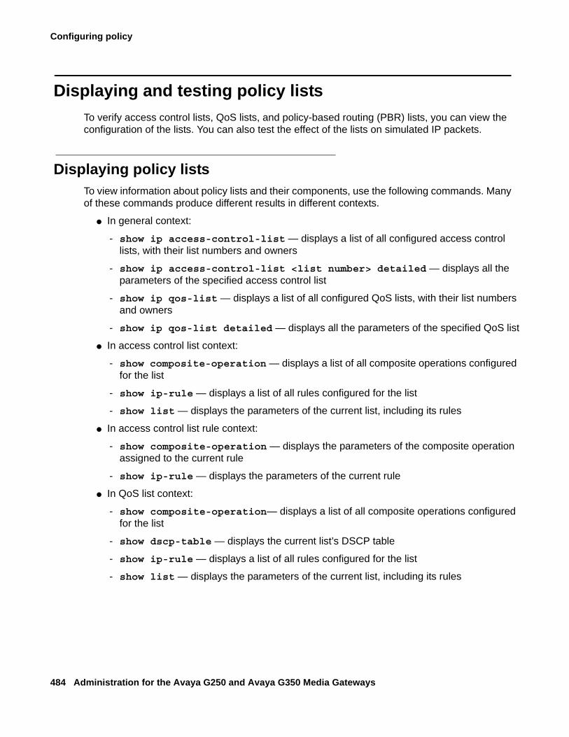
Configuring policy
484 Administration for the Avaya G250 and Avaya G350 Media Gateways
Displaying and testing policy listsTo verify access control lists, QoS lists, and policy-based routing (PBR) lists, you can view the configuration of the lists. You can also test the effect of the lists on simulated IP packets.
Displaying policy listsTo view information about policy lists and their components, use the following commands. Many of these commands produce different results in different contexts.
● In general context:
- show ip access-control-list — displays a list of all configured access control lists, with their list numbers and owners
- show ip access-control-list <list number> detailed — displays all the parameters of the specified access control list
- show ip qos-list — displays a list of all configured QoS lists, with their list numbers and owners
- show ip qos-list detailed — displays all the parameters of the specified QoS list
● In access control list context:
- show composite-operation — displays a list of all composite operations configured for the list
- show ip-rule — displays a list of all rules configured for the list
- show list — displays the parameters of the current list, including its rules
● In access control list rule context:
- show composite-operation — displays the parameters of the composite operation assigned to the current rule
- show ip-rule — displays the parameters of the current rule
● In QoS list context:
- show composite-operation— displays a list of all composite operations configured for the list
- show dscp-table — displays the current list’s DSCP table
- show ip-rule — displays a list of all rules configured for the list
- show list — displays the parameters of the current list, including its rules
Displaying and testing policy lists
Issue 2 February 2006 485
● In QoS list rule context:
- show composite-operation — displays the parameters of the composite operation assigned to the current rule
- show dscp-table — displays the current list’s DSCP table
- show ip-rule — displays the parameters of the current rule
● In QoS list DSCP table context:
- show dscp-table — displays the parameters of the current DSCP table entry
● In QoS list composite operation context:
- show composite-operation — displays the parameters of the current composite operation
Simulating packetsUse the ip simulate command in the context of an interface to test a policy list. The command tests the effect of the policy list on a simulated IP packet in the interface. You must specify the number of a policy list, the direction of the packet (in or out), and a source and destination IP address. You may also specify other parameters. For a full list of parameters, see Avaya G250 and Avaya G350 CLI Reference, 03-300437.
The following command simulates the effect of applying QoS list number 401 to a packet entering the G350 through interface VLAN 2:
The simulated packet has the following properties:
● CoS priority is 1
● DSCP is 46
● source IP address is 10.1.1.1.
● destination IP address is 10.2.2.2.
● IP protocol is TCP
● source TCP port is 1182
● destination TCP port is 20
G350-001(if:Vlan 2)# ip simulate 401 in CoS1 dscp46 10.1.1.1 10.2.2.2 tcp 1182 20

Configuring policy
486 Administration for the Avaya G250 and Avaya G350 Media Gateways
When you run the ip simulate command, the G250/G350 displays the effect of the policy rules on the simulated packet. For example:
G350-001(super-if:Vlan 2)# ip simulate 401 in CoS1 dscp46 10.1.1.1 10.2.2.2 tcp 1182 20Rule match for simulated packet is the default ruleComposite action for simulated packet is CoS6New priority value is fwd6Dscp value is not changed
Issue 2 February 2006 487
Chapter 21: Configuring policy-based routing
This chapter provides information about configuring policy-based routing on the G250/G350 and contains the following sections:
● Policy-based routing overview — an overview of policy-based routing
● Applications — a description of common policy-based routing applications
● Configuring policy-based routing — instructions on how to configure policy-based routing
● PBR rules — instructions on how to configure rules
● Next hop lists — instructions on how to configure next hop lists
● Editing and Deleting PBR lists — instructions on how to modify and delete PBR lists
● Displaying PBR lists — instructions on how to view the configuration of PBR lists
● Application example — an example of a policy-based routing application
Policy-based routing overviewPolicy-based routing allows you to configure a routing scheme based on traffic’s source IP address, destination IP address, IP protocol, and other characteristics. You can use policy-based routing (PBR) lists to determine the routing of packets that match the rules defined in the list. Each PBR list includes a set of rules, and each rule includes a next hop list. Each next hop list contains up to 20 next hop destinations to which the G250/G350 sends packets that match the rule. A destination can be either an IP address or an interface.
Policy-based routing takes place only when the packet enters the interface, not when it leaves. Policy-based routing takes place after the packet is processed by the Ingress Access Control List and the Ingress QoS list. Thus, the PBR list evaluates the packet after the packet’s DSCP field has been modified by the Ingress QoS List. See Figure 49: Applying Policy Lists to Packets on page 470.
Note:Note: The Loopback 1 interface is an exception to this rule. On the Loopback 1
interface, PBR lists are applied when the packet leaves the interface. This enables the PBR list to handle packets sent by the G250/G350 device itself, as explained below.
Note:Note: ICMP keepalive provides the interface with the ability to determine whether a
next hop is or is not available. See ICMP keepalive on page 183.
Configuring policy-based routing
488 Administration for the Avaya G250 and Avaya G350 Media Gateways
Policy-based routing only operates on routed packets. Packets traveling within the same subnet are not routed, and are therefore not affected by policy-based routing.
The Loopback interface is a logical interface which handles traffic that is sent to and from the G250/G350 itself. This includes ping packets to or from the G250/G350, as well as telnet, FTP, DHCP Relay, TFTP, HTTP, NTP, SNMP, H.248, and other types of traffic. The Loopback interface is also used for traffic to and from analog and DCP phones connected to the device via IP phone entities.
The Loopback interface is always up. You should attach a PBR list to the Loopback interface if you want to route specific packets generated by the G250/G350 to a specific next-hop.
Unlike the case with other interfaces, PBR lists on the Loopback interface are applied to packets when they leave the G250/G350, rather than when they enter.
Certain types of packets are not considered router packets (on the Loopback interface only), and are therefore not affected by policy-based routing. These include RIP, OSPF, VRRP, GRE, and keepalive packets. On the other hand, packets using SNMP, Telnet, Bootp, ICMP, FTP, SCP, TFTP, HTTP, NTP, and H.248 protocols are considered routed packets, and are therefore affected by policy-based routing on the Loopback interface.
ApplicationsThe most common application for policy-based routing is to provide for separate routing of voice and data traffic. It can also be used as a means to provide backup routes for defined traffic types.
Separate routing of voice and data trafficAlthough there are many possible applications for policy-based routing, the most common application is to create separate routing for voice and data traffic.
For example, the application shown in Figure 50: Policy-based routing — Voice/Data Division By DSCP on page 489 uses the DSCP field to identify VoIP control packets (DSCP=34, 41), VoIP Bearer RESV packets (DSCP = 43, 44), and VoIP Bearer packets (DSCP = 46). Policy-based routing sends these packets over the T1 WAN line, and sends other packets over the Internet. This saves bandwidth on the more expensive serial interface.
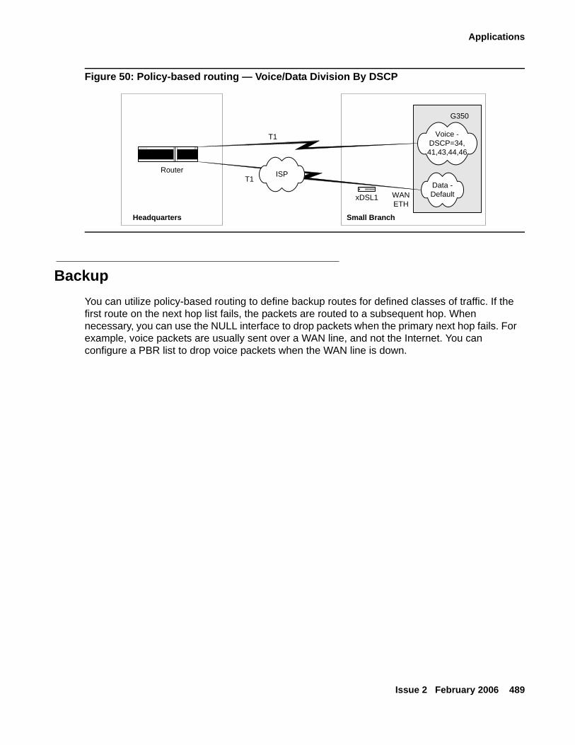
Applications
Issue 2 February 2006 489
Figure 50: Policy-based routing — Voice/Data Division By DSCP
BackupYou can utilize policy-based routing to define backup routes for defined classes of traffic. If the first route on the next hop list fails, the packets are routed to a subsequent hop. When necessary, you can use the NULL interface to drop packets when the primary next hop fails. For example, voice packets are usually sent over a WAN line, and not the Internet. You can configure a PBR list to drop voice packets when the WAN line is down.
Router
Headquarters Small Branch
Voice -DSCP=34,41,43,44,46
Data -Default
ISP
xDSL1
G350
T1
T1
WANETH
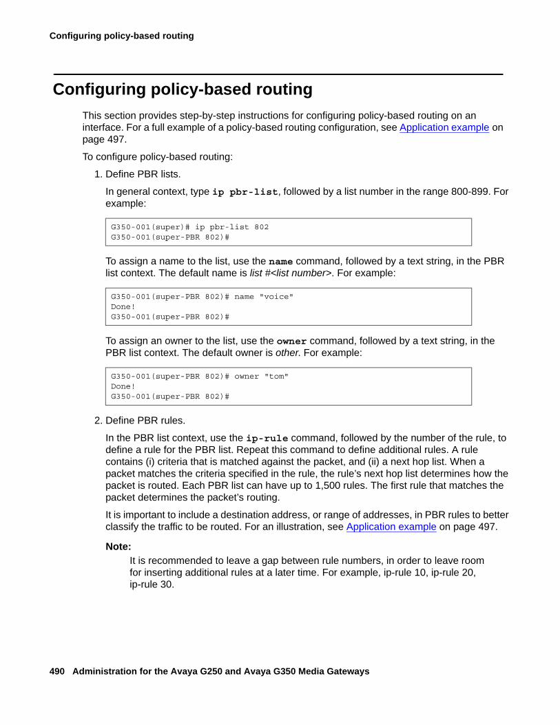
Configuring policy-based routing
490 Administration for the Avaya G250 and Avaya G350 Media Gateways
Configuring policy-based routingThis section provides step-by-step instructions for configuring policy-based routing on an interface. For a full example of a policy-based routing configuration, see Application example on page 497.
To configure policy-based routing:
1. Define PBR lists.
In general context, type ip pbr-list, followed by a list number in the range 800-899. For example:
To assign a name to the list, use the name command, followed by a text string, in the PBR list context. The default name is list #<list number>. For example:
To assign an owner to the list, use the owner command, followed by a text string, in the PBR list context. The default owner is other. For example:
2. Define PBR rules.
In the PBR list context, use the ip-rule command, followed by the number of the rule, to define a rule for the PBR list. Repeat this command to define additional rules. A rule contains (i) criteria that is matched against the packet, and (ii) a next hop list. When a packet matches the criteria specified in the rule, the rule’s next hop list determines how the packet is routed. Each PBR list can have up to 1,500 rules. The first rule that matches the packet determines the packet’s routing.
It is important to include a destination address, or range of addresses, in PBR rules to better classify the traffic to be routed. For an illustration, see Application example on page 497.
Note:Note: It is recommended to leave a gap between rule numbers, in order to leave room
for inserting additional rules at a later time. For example, ip-rule 10, ip-rule 20, ip-rule 30.
G350-001(super)# ip pbr-list 802G350-001(super-PBR 802)#
G350-001(super-PBR 802)# name "voice"Done!G350-001(super-PBR 802)#
G350-001(super-PBR 802)# owner "tom"Done!G350-001(super-PBR 802)#
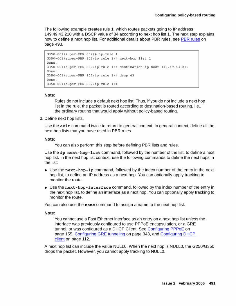
Configuring policy-based routing
Issue 2 February 2006 491
The following example creates rule 1, which routes packets going to IP address 149.49.43.210 with a DSCP value of 34 according to next hop list 1. The next step explains how to define a next hop list. For additional details about PBR rules, see PBR rules on page 493.
Note:Note: Rules do not include a default next hop list. Thus, if you do not include a next hop
list in the rule, the packet is routed according to destination-based routing, i.e., the ordinary routing that would apply without policy-based routing.
3. Define next hop lists.
Use the exit command twice to return to general context. In general context, define all the next hop lists that you have used in PBR rules.
Note:Note: You can also perform this step before defining PBR lists and rules.
Use the ip next-hop-list command, followed by the number of the list, to define a next hop list. In the next hop list context, use the following commands to define the next hops in the list:
● Use the next-hop-ip command, followed by the index number of the entry in the next hop list, to define an IP address as a next hop. You can optionally apply tracking to monitor the route.
● Use the next-hop-interface command, followed by the index number of the entry in the next hop list, to define an interface as a next hop. You can optionally apply tracking to monitor the route.
You can also use the name command to assign a name to the next hop list.
Note:Note: You cannot use a Fast Ethernet interface as an entry on a next hop list unless the
interface was previously configured to use PPPoE encapsulation, or a GRE tunnel, or was configured as a DHCP Client. See Configuring PPPoE on page 155, Configuring GRE tunneling on page 343, and Configuring DHCP client on page 112.
A next hop list can include the value NULL0. When the next hop is NULL0, the G250/G350 drops the packet. However, you cannot apply tracking to NULL0.
G350-001(super-PBR 802)# ip-rule 1G350-001(super-PBR 802/ip rule 1)# next-hop list 1Done!G350-001(super-PBR 802/ip rule 1)# destination-ip host 149.49.43.210Done!G350-001(super-PBR 802/ip rule 1)# dscp 43Done!G350-001(super-PBR 802/ip rule 1)#
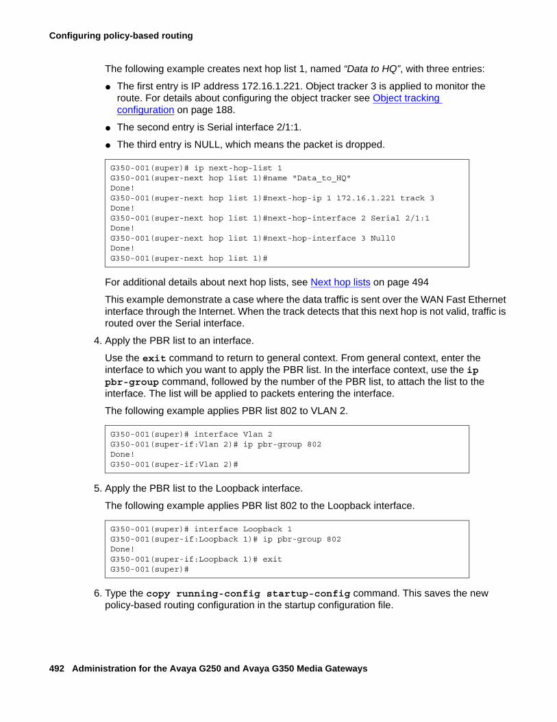
Configuring policy-based routing
492 Administration for the Avaya G250 and Avaya G350 Media Gateways
The following example creates next hop list 1, named “Data to HQ”, with three entries:
● The first entry is IP address 172.16.1.221. Object tracker 3 is applied to monitor the route. For details about configuring the object tracker see Object tracking configuration on page 188.
● The second entry is Serial interface 2/1:1.
● The third entry is NULL, which means the packet is dropped.
For additional details about next hop lists, see Next hop lists on page 494
This example demonstrate a case where the data traffic is sent over the WAN Fast Ethernet interface through the Internet. When the track detects that this next hop is not valid, traffic is routed over the Serial interface.
4. Apply the PBR list to an interface.
Use the exit command to return to general context. From general context, enter the interface to which you want to apply the PBR list. In the interface context, use the ip pbr-group command, followed by the number of the PBR list, to attach the list to the interface. The list will be applied to packets entering the interface.
The following example applies PBR list 802 to VLAN 2.
5. Apply the PBR list to the Loopback interface.
The following example applies PBR list 802 to the Loopback interface.
6. Type the copy running-config startup-config command. This saves the new policy-based routing configuration in the startup configuration file.
G350-001(super)# ip next-hop-list 1G350-001(super-next hop list 1)#name "Data_to_HQ"Done!G350-001(super-next hop list 1)#next-hop-ip 1 172.16.1.221 track 3Done!G350-001(super-next hop list 1)#next-hop-interface 2 Serial 2/1:1Done!G350-001(super-next hop list 1)#next-hop-interface 3 Null0Done!G350-001(super-next hop list 1)#
G350-001(super)# interface Vlan 2G350-001(super-if:Vlan 2)# ip pbr-group 802Done!G350-001(super-if:Vlan 2)#
G350-001(super)# interface Loopback 1G350-001(super-if:Loopback 1)# ip pbr-group 802Done!G350-001(super-if:Loopback 1)# exitG350-001(super)#
PBR rules
Issue 2 February 2006 493
PBR rulesEach PBR list can have up to 1,500 rules. The first rule that matches the packet specifies the next hop list for the packet. If no rule matches the packet, the packet is routed according to the default rule.
This section provides information on how to configure rules in a PBR list and contains the following topics:
● Overview of rule criteria — an overview of the criteria that can be used in configuring PBR rules
● Modifying rules — instructions on how to create and edit a PBR rule
● Rule criteria — instructions on how to configure a PBR rule’s criteria
Overview of rule criteriaYou can configure policy rules to match packets based on one or more of the following criteria:
● Source IP address, or a range of addresses
● Destination IP address or a range of addresses
● IP protocol, such as TCP, UDP, ICMP, IGMP
● Source TCP or UDP port or a range of ports
● Destination TCP or UDP port or a range of ports
● ICMP type and code
● Fragments
● DSCP field
Note:Note: The fragment criteria is used for non-initial fragments only.
Use IP wildcards to specify a range of source or destination IP addresses. The zero bits in the wildcard correspond to bits in the IP address that remain fixed. The one bits in the wildcard correspond to bits in the IP address that can vary. Note that this is the opposite of how bits are used in a subnet mask.
Note:Note: When you use destination and source ports in a PBR rule, policy-based routing
does not catch fragments.
Configuring policy-based routing
494 Administration for the Avaya G250 and Avaya G350 Media Gateways
Note:Note: It is recommended to leave a gap between rule numbers, in order to leave room
for inserting additional rules at a later time. For example, ip-rule 10, ip-rule 20, ip-rule 30.
Modifying rulesTo modify a policy-based routing rule, you must enter the context of the rule and redefine the rule criteria.
To enter a rule context:
1. Enter the context of the PBR list to which the rule belongs.
2. Type the command ip-rule, followed by the number of the rule you want to modify. For example, to create rule 1, type ip-rule 1.
To view the rules that belong to a PBR list, enter the list’s context and type ip show-rule.
Rule criteriaThe rule criteria for PBR rules are largely the same as the rule criteria for other policy list rules. Refer to Rule criteria on page 474.
Unlike other policy lists, PBR lists do not use composite operations. Thus, there is no operation command in the context of a PBR rule. Instead, PBR lists use next hop lists. For an explanation of next hop lists, see Next hop lists on page 494.
Use the next-hop list command, followed by the list number of a next hop list, to specify a next hop list for the G250/G350 to apply to packets that match the rule. You can specify Destination Based Routing instead of a next hop list, in which case the G250/G350 applies destination-based routing to a packet when the packet matches the rule.
If the next hop list specified in the rule does not exist, the G250/G350 applies destination-based routing to packets that match the rule.
Next hop listsPBR rules include a next hop list. When the rule matches a packet, the G250/G350 routes the packet according to the specified next hop list.
This section describes next hop lists and contains the following topics:
● Next hop list overview — an overview of next hop lists
● Modifying next hop lists — instructions on how to modify a next hop list
Next hop lists
Issue 2 February 2006 495
Next hop list overviewEach next hop list can include up to 20 entries. An entry in a next hop list can be either an IP address or an interface. The G250/G350 attempts to route the packet to the first available destination on the next hop list. If every destination on the list is unavailable, the G250/G350 routes the packet according to destination-based routing.
Modifying next hop listsTo modify a next hop list, you must enter the context of the next hop list. To enter a next hop list context, type the command ip next-hop-list, followed by the number of the list you want to edit. For example, to modify next hop list 1, type ip next-hop-list 1.
To show the next hops in an existing list, enter the context of the next hop list and type show next-hop.
To add entries to a next hop list:
1. Enter the context of the next hop list.
2. Use one of the following commands:
- To enter an IP address as a next hop, use the next-hop-ip command, followed by the index number of the entry and the IP address. You can optionally apply tracking to monitor the route. For example, the command next-hop-ip 2 149.49.200.2 track 3 sets the IP address 149.49.200.2 as the second entry on the next hop list and applies object tracker 3 to monitor the route.
- To enter an interface as a next hop, use the next-hop-interface command, followed by the index number of the entry and the name of the interface. You can optionally apply tracking to monitor the route, except for the NULL0. For example, the command next-hop-interface 3 Serial 5/1:1.1 sets Serial 5/1:1.1as the third entry on the next hop list.
To delete an entry from a next hop list:
1. Enter the context of the next hop list.
2. Use one of the following commands:
- To delete an IP address, use the no next-hop-ip command, followed by the index number of the entry you want to delete. For example, the command no next-hop-ip 2 deletes the second entry from the next hop list.
- To delete an interface, use the no next-hop-interface command, followed by the index number of the entry you want to delete. For example, the command no next-hop-interface 3 deletes the third entry from the next hop list.
Configuring policy-based routing
496 Administration for the Avaya G250 and Avaya G350 Media Gateways
To cancel tracking and keep the next hop:
1. Enter the context of the next hop list.
2. Use the next-hop-ip or next-hop-interface command again, without the track keyword.
To change the object tracker and keep the next hop:
1. Enter the context of the next hop list.
2. Use the next-hop-ip or next-hop-interface command again, with the track keyword followed by the new track index.
Editing and Deleting PBR listsYou cannot delete or modify a PBR list when it is attached to an interface. In order to delete or modify a PBR list, you must first remove the list from the interface. You can then delete or modify the list. After modifying the list, you can reattach the list to the interface.
To remove a list from an interface, use the no form of the ip pbr-group command in the interface context. The following example removes the PBR list from the Vlan 2 interface.
To modify a PBR list, type ip pbr-list, followed by the number of the list you want to modify, to enter the list context. Redefine the parameters of the list.
To delete a PBR list, use the exit command to return to general context and type no ip pbr-list, followed by the number of the list you want to delete.
Displaying PBR listsTo view information about PBR lists and their components, use the following commands. Many of these commands produce different results in different contexts.
● In general context:- show ip pbr-list — displays a list of all configured PBR lists, with their list numbers
and names and their owners- show ip pbr-list list number — displays the list number and name of the
specified PBR list
G350-001(super)# interface Vlan 1G350-001(super-if:Vlan 1)# no ip pbr-groupDone!G350-001(super-if:Vlan 1)#
Application example
Issue 2 February 2006 497
- show ip pbr-list all detailed — displays all the parameters of all configured PBR lists
- show ip pbr-list list number detailed — displays all the parameters of the specified PBR list
- show ip active-lists — displays a list of each G250/G350 interface to which a PBR list is attached, along with the number and name of the PBR list
- show ip active-lists list number — displays a list of each G250/G350 interface to which the specified PBR list is attached, along with the number and name of the PBR list
- show ip next-hop-list all — displays the number and name of all next hop lists- show ip next-hop-list list number — displays the number and name of the
specified next hop list
● In PBR list context:
- show list — displays all the parameters of the current PBR list
- show ip-rule — displays the parameters of all rules configured for the current list
- show ip-rule rule number — displays the parameters of the specified rule
● In next hop list context:
- show next-hop — displays the next hop entries in the current next hop list and their current status
Application exampleThe following example creates a policy-based routing scheme in which:
● Voice traffic is routed over a serial interface. If the interface is down, the traffic is dropped.
● Data traffic is routed over a GRE tunnel. If the tunnel is down, the traffic is routed over the serial interface. If both interfaces are down, the traffic is dropped.
Figure 51: Sample policy-based routing application on page 498 illustrates the sample application described below.
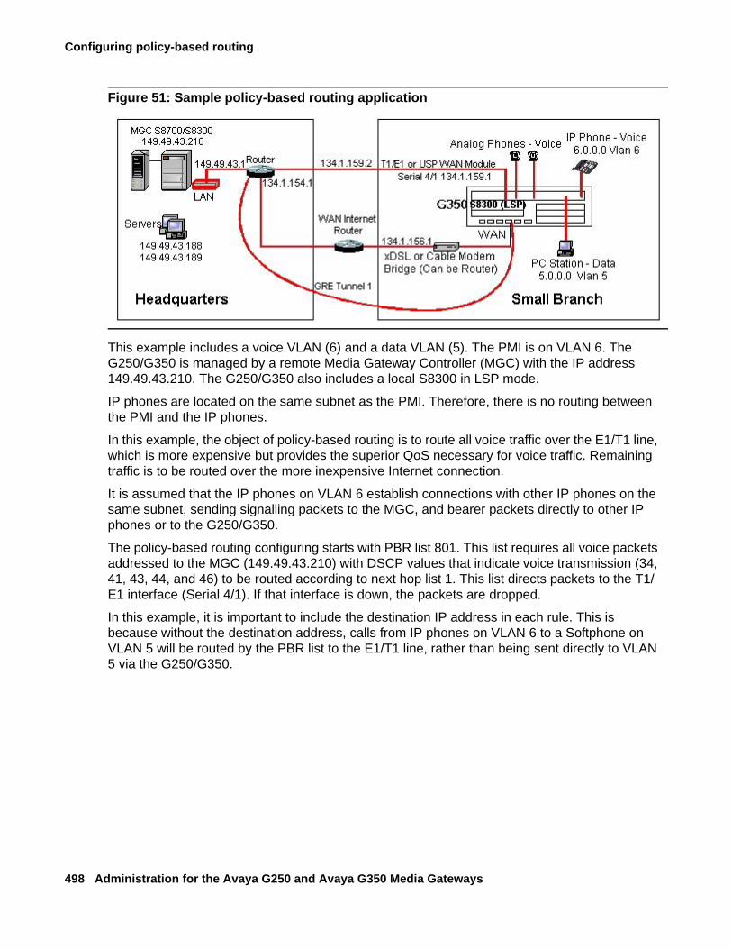
Configuring policy-based routing
498 Administration for the Avaya G250 and Avaya G350 Media Gateways
Figure 51: Sample policy-based routing application
This example includes a voice VLAN (6) and a data VLAN (5). The PMI is on VLAN 6. The G250/G350 is managed by a remote Media Gateway Controller (MGC) with the IP address 149.49.43.210. The G250/G350 also includes a local S8300 in LSP mode.
IP phones are located on the same subnet as the PMI. Therefore, there is no routing between the PMI and the IP phones.
In this example, the object of policy-based routing is to route all voice traffic over the E1/T1 line, which is more expensive but provides the superior QoS necessary for voice traffic. Remaining traffic is to be routed over the more inexpensive Internet connection.
It is assumed that the IP phones on VLAN 6 establish connections with other IP phones on the same subnet, sending signalling packets to the MGC, and bearer packets directly to other IP phones or to the G250/G350.
The policy-based routing configuring starts with PBR list 801. This list requires all voice packets addressed to the MGC (149.49.43.210) with DSCP values that indicate voice transmission (34, 41, 43, 44, and 46) to be routed according to next hop list 1. This list directs packets to the T1/E1 interface (Serial 4/1). If that interface is down, the packets are dropped.
In this example, it is important to include the destination IP address in each rule. This is because without the destination address, calls from IP phones on VLAN 6 to a Softphone on VLAN 5 will be routed by the PBR list to the E1/T1 line, rather than being sent directly to VLAN 5 via the G250/G350.
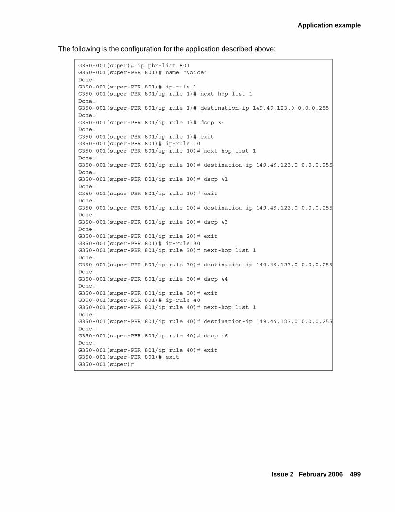
Application example
Issue 2 February 2006 499
The following is the configuration for the application described above:
G350-001(super)# ip pbr-list 801G350-001(super-PBR 801)# name "Voice"Done!G350-001(super-PBR 801)# ip-rule 1G350-001(super-PBR 801/ip rule 1)# next-hop list 1Done!G350-001(super-PBR 801/ip rule 1)# destination-ip 149.49.123.0 0.0.0.255Done!G350-001(super-PBR 801/ip rule 1)# dscp 34Done!G350-001(super-PBR 801/ip rule 1)# exitG350-001(super-PBR 801)# ip-rule 10G350-001(super-PBR 801/ip rule 10)# next-hop list 1Done!G350-001(super-PBR 801/ip rule 10)# destination-ip 149.49.123.0 0.0.0.255Done!G350-001(super-PBR 801/ip rule 10)# dscp 41Done!G350-001(super-PBR 801/ip rule 10)# exitDone!G350-001(super-PBR 801/ip rule 20)# destination-ip 149.49.123.0 0.0.0.255Done!G350-001(super-PBR 801/ip rule 20)# dscp 43Done!G350-001(super-PBR 801/ip rule 20)# exitG350-001(super-PBR 801)# ip-rule 30G350-001(super-PBR 801/ip rule 30)# next-hop list 1Done!G350-001(super-PBR 801/ip rule 30)# destination-ip 149.49.123.0 0.0.0.255Done!G350-001(super-PBR 801/ip rule 30)# dscp 44Done!G350-001(super-PBR 801/ip rule 30)# exitG350-001(super-PBR 801)# ip-rule 40G350-001(super-PBR 801/ip rule 40)# next-hop list 1Done!G350-001(super-PBR 801/ip rule 40)# destination-ip 149.49.123.0 0.0.0.255Done!G350-001(super-PBR 801/ip rule 40)# dscp 46Done!G350-001(super-PBR 801/ip rule 40)# exitG350-001(super-PBR 801)# exitG350-001(super)#

Configuring policy-based routing
500 Administration for the Avaya G250 and Avaya G350 Media Gateways
The next group of commands configures next hop list 1, which was included in the rules configured above. Next hop list 1 sends packets that match the rule in which it is included to the E1/T1 line (serial interface 4/1). If that interface is not available, the next hop list requires the packet to be dropped (Null0). This is because the QoS on the Internet interface is not adequate for voice packets. It would also be possible to include one or more backup interfaces in the next hop list.
The next set of commands applies the PBR list to the voice VLAN (6).
The next set of commands applies the PBR list to the Loopback interface. This is necessary to ensure that voice packets generated by the G250/G350 itself are routed via the E1/T1 line. The Loopback interface is a logical interface that is always up. Packets sent from the G250/G350, such as signaling packets, are sent via the Loopback interface. In this example, applying PBR list 801 to the Loopback interface ensures that signaling packets originating from voice traffic are sent via the T1/E1 line.
G350-001(super)# ip next-hop-list 1G350-001(super-next hop list 1)#name "Voice-To_HQ"Done!G350-001(super-next hop list 1)#next-hop-interface 1 Serial 4/1Done!G350-001(super-next hop list 1)#next-hop-interface 2 Null0Done!G350-001(super-next hop list 1)#exitG350-001(super)#
G350-001(super)# interface Vlan 6G350-001(super-if:Vlan 6)# ip pbr-group 801Done!G350-001(super-if:Vlan 6)# exitG350-001(super)#
G350-001(super)# interface Loopback 1G350-001(super-if:Loopback 1)# ip pbr-group 801Done!G350-001(super-if:Loopback 1)# exitG350-001(super)#
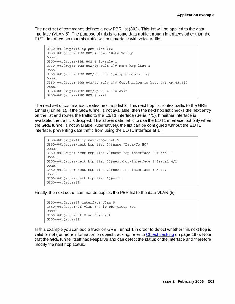
Application example
Issue 2 February 2006 501
The next set of commands defines a new PBR list (802). This list will be applied to the data interface (VLAN 5). The purpose of this is to route data traffic through interfaces other than the E1/T1 interface, so that this traffic will not interface with voice traffic.
The next set of commands creates next hop list 2. This next hop list routes traffic to the GRE tunnel (Tunnel 1). If the GRE tunnel is not available, then the next hop list checks the next entry on the list and routes the traffic to the E1/T1 interface (Serial 4/1). If neither interface is available, the traffic is dropped. This allows data traffic to use the E1/T1 interface, but only when the GRE tunnel is not available. Alternatively, the list can be configured without the E1/T1 interface, preventing data traffic from using the E1/T1 interface at all.
Finally, the next set of commands applies the PBR list to the data VLAN (5).
In this example you can add a track on GRE Tunnel 1 in order to detect whether this next hop is valid or not (for more information on object tracking, refer to Object tracking on page 187). Note that the GRE tunnel itself has keepalive and can detect the status of the interface and therefore modify the next hop status.
G350-001(super)# ip pbr-list 802G350-001(super-PBR 802)# name "Data_To_HQ"Done!G350-001(super-PBR 802)# ip-rule 1G350-001(super-PBR 802/ip rule 1)# next-hop list 2Done!G350-001(super-PBR 802/ip rule 1)# ip-protocol tcpDone!G350-001(super-PBR 802/ip rule 1)# destination-ip host 149.49.43.189Done!G350-001(super-PBR 802/ip rule 1)# exitG350-001(super-PBR 802)# exit
G350-001(super)# ip next-hop-list 2G350-001(super-next hop list 2)#name "Data-To_HQ"Done!G350-001(super-next hop list 2)#next-hop-interface 1 Tunnel 1Done!G350-001(super-next hop list 2)#next-hop-interface 2 Serial 4/1Done!G350-001(super-next hop list 2)#next-hop-interface 3 Null0Done!G350-001(super-next hop list 2)#exitG350-001(super)#
G350-001(super)# interface Vlan 5G350-001(super-if:Vlan 6)# ip pbr-group 802Done!G350-001(super-if:Vlan 6)# exitG350-001(super)#

Configuring policy-based routing
502 Administration for the Avaya G250 and Avaya G350 Media Gateways
Simulating packetsPolicy-based routing supports the IP simulate command for testing policies. Refer to Simulating packets on page 485.
Issue 2 February 2006 503
Chapter 22: Setting synchronization
If the Avaya G350 Media Gateway contains an MM710 T1/E1 media module, it is advisable to define the MM710 as the primary synchronization source for the G350. In so doing, clock synchronization signals from the Central Office (CO) are used by the MM710 to synchronize all operations of the G350. If no MM710 is present, it is not necessary to set synchronization.
Note:Note: The Avaya G250 Media Gateway cannot contain an MM710 T1/E1 media
module, and clock synchronization is not configurable through the CLI on the G250.
Use the set sync interface command to define a potential stratum clock source (T1/E1 Media Module, ISDN-BRI), where:
● mmID is the Media Module ID of an MM stratum clock source of the form vn, where n is the MM slot number.
● portID is the port number for an ISDN clock source candidate. The port ID consists of the slot number of the media module and the number of the port. You can set more than one port. For example: v2 1,3,5-8.
Note:Note: The port ID parameter only applies if the source is a BRI module.
By setting the clock source to primary, normal failover will occur. The identity of the current synchronization source is not stored in persistent storage. Persistent storage is used to preserve the parameters set by this command.
Note:Note: Setting the source to secondary overrides normal failover, generates a trap, and
asserts a fault. Thus, it is not recommended to set the clock source to secondary except for testing purposes.
To determine which reference source is the active source, use the set sync source primary|secondary command. If you choose secondary, the secondary source becomes active, and the primary source goes on standby. In addition, fallback to the primary source does not occur even when the primary source becomes available.
If neither primary nor secondary sources are identified, the local clock becomes the active source.
The following example sets the MM710 media module located in slot 2 of the G350 chassis as the primary clock synchronization source for the Avaya G350 Media Gateway.
set sync interface primary v2set sync source primary
Setting synchronization
504 Administration for the Avaya G250 and Avaya G350 Media Gateways
If the G350 includes a second MM710 media module, enter the following additional command:
set sync interface secondary v3set sync source secondary
If, for any reason, the primary MM710 media module cannot function as the clock synchronization source, the system uses the MM710 media module located in slot 3 of the G350 chassis as the clock synchronization source. If neither MM710 media module can function as the clock synchronization source, the system defaults to the local clock running on the S8300 Media Server.
The yellow ACT LED on the front of the MM710 media module displays the synchronization status of that module.
● If the yellow ACT LED is solidly on or off, it has not been defined as a synchronization source. If it is on, one or more channels is active. If it is an ISDN facility, the D-channel counts as an active channel and causes the yellow ACT LED to be on.
● When the MM710 is operating as a clock synchronization source, the yellow ACT LED indicates that the MM710 is the clock synchronization source by flashing at three second intervals.
- The yellow ACT LED is on for 2.8 seconds and off for 200 milliseconds if the MM710 media module has been specified as a clock synchronization source and is receiving a signal that meets the minimum requirements for the interface.
- The yellow ACT LED is on for 200 milliseconds and off for 2.8 seconds if the MM710 media module has been specified as a synchronization source and is not receiving a signal, or is receiving a signal that does not meet the minimum requirements for the interface.
Displaying synchronization statusUse the show sync timing command to display the status of the primary, secondary, and local clock sources. The status can be Active, Standby, or Not Configured. The status is Not Configured when a source has not been defined, for example, when there are no T1 cards installed.
Issue 2 February 2006 505
Chapter 23: FIPS
This chapter provides information about (i) the Avaya Branch Office Media Gateways (G250, G250-BRI, and G350) cryptographic modules’ compliance with the Federal Information Processing Standard (FIPS-140-2) for cryptographic modules, and (ii) how to configure the module to work in FIPS mode. This chapter includes the following sections:
● Overview — an overview of the Media Gateway (relating to FIPS compliance)
● Security rules — the security rules enforced by the cryptographic module to implement the security requirements of FIPS
● Password guidelines — the general guidelines for defining passwords
● Managing the module in FIPS-compliant mode — a description of the behavior of the module working in FIPS-approved mode of operation
● Administration procedures — step-by-step instructions on how to enter FIPS mode, failure scenarios, repair actions, and error states
OverviewThe G250, G250-BRI, and G350 are multi-chip stand-alone cryptographic modules in commercial grade metal cases. The modules provide:
● VPN, Voice over Internet Protocol (VoIP) media-gateway services, Ethernet switching, IP routing, and data security for IP traffic
● Status output via LEDs and logs available through the module’s management interface
● Network interfaces for data input and output
● A console port
The cryptographic boundary includes all of the components within the physical enclosure of the branch gateway chassis, without any expansion modules. The figures below illustrate these modules and their interfaces:
● G250-Analog (refer to Figure 52)
● G250-BRI (refer to Figure 53)
● G250-DCP (refer to Figure 54)
● G250-DS1 (refer to Figure 55)
● G350 (refer to Figure 56)
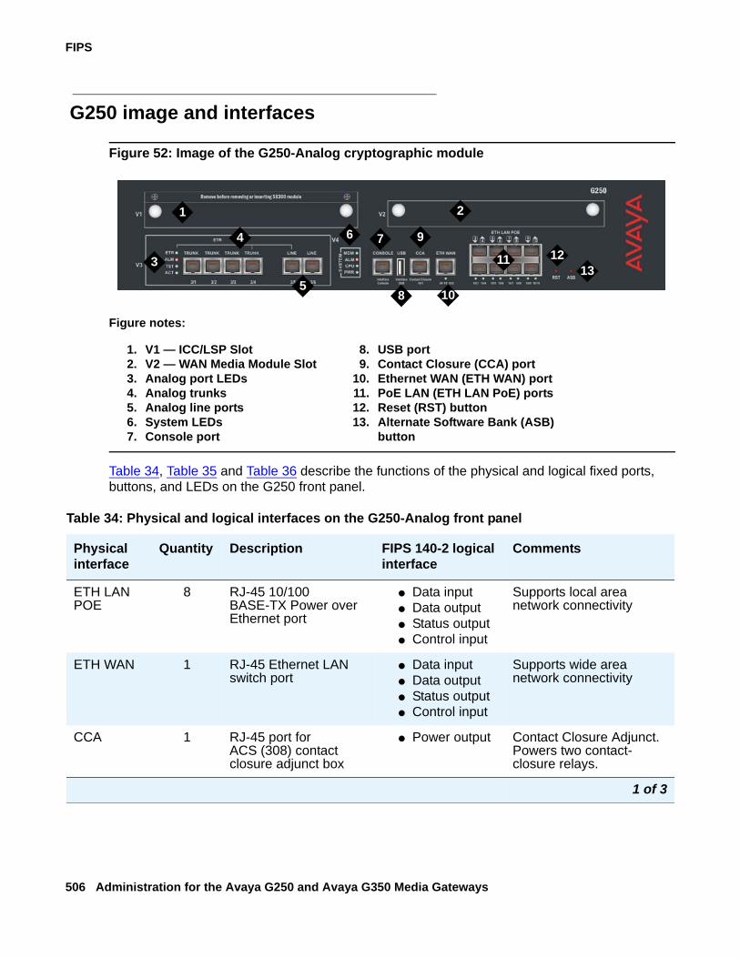
FIPS
506 Administration for the Avaya G250 and Avaya G350 Media Gateways
G250 image and interfaces
Figure 52: Image of the G250-Analog cryptographic module
Table 34, Table 35 and Table 36 describe the functions of the physical and logical fixed ports, buttons, and LEDs on the G250 front panel.
Figure notes:
1. V1 — ICC/LSP Slot2. V2 — WAN Media Module Slot3. Analog port LEDs4. Analog trunks5. Analog line ports6. System LEDs7. Console port
8. USB port9. Contact Closure (CCA) port
10. Ethernet WAN (ETH WAN) port11. PoE LAN (ETH LAN PoE) ports12. Reset (RST) button13. Alternate Software Bank (ASB)
button
2
3
4
513
1211
1
6 7
8
9
10
Table 34: Physical and logical interfaces on the G250-Analog front panel
Physical interface
Quantity Description FIPS 140-2 logical interface
Comments
ETH LAN POE
8 RJ-45 10/100 BASE-TX Power over Ethernet port
● Data input● Data output● Status output● Control input
Supports local area network connectivity
ETH WAN 1 RJ-45 Ethernet LAN switch port
● Data input● Data output● Status output● Control input
Supports wide area network connectivity
CCA 1 RJ-45 port for ACS (308) contact closure adjunct box
● Power output Contact Closure Adjunct. Powers two contact-closure relays.
1 of 3
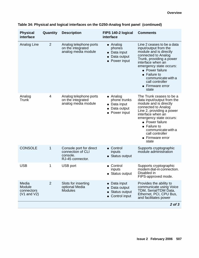
Overview
Issue 2 February 2006 507
Analog Line 2 Analog telephone ports on the integrated analog media module
● Analog phones
● Data input● Data output● Power input
Line 2 ceases to be a data input/output from the module and is directly connected to Analog Trunk, providing a power interface when an emergency state occurs:
● Power failure● Failure to
communicate with a call controller
● Firmware error state
Analog Trunk
4 Analog telephone ports on the integrated analog media module
● Analog phone trunks
● Data input● Data output● Power input
The Trunk ceases to be a data input/output from the module and is directly connected to Analog Line 2, providing a power interface when an emergency state occurs:
● Power failure● Failure to
communicate with a call controller
● Firmware error state
CONSOLE 1 Console port for direct connection of CLI console.RJ-45 connector.
● Control inputs
● Status output
Supports cryptographic module administration
USB 1 USB port ● Control inputs
● Status output
Supports cryptographic modem dial-in connection. Disabled in FIPS-approved mode.
Media Module connectors (V1 and V2)
2 Slots for inserting optional Media Modules
● Data input● Data output● Status output● Control input
Provides the ability to communicate using Voice TDM, Serial/TDM Data, Ethernet, PCI, CPU Bus, and facilitates power
Table 34: Physical and logical interfaces on the G250-Analog front panel (continued)
Physical interface
Quantity Description FIPS 140-2 logical interface
Comments
2 of 3
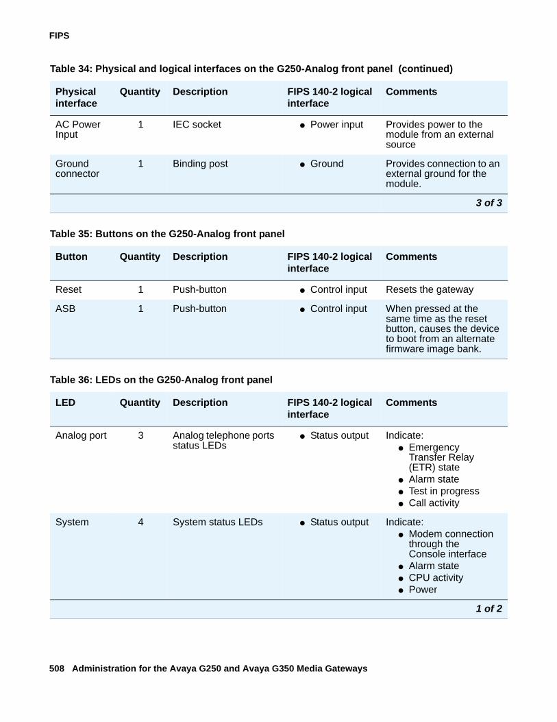
FIPS
508 Administration for the Avaya G250 and Avaya G350 Media Gateways
AC Power Input
1 IEC socket ● Power input Provides power to the module from an external source
Ground connector
1 Binding post ● Ground Provides connection to an external ground for the module.
Table 34: Physical and logical interfaces on the G250-Analog front panel (continued)
Physical interface
Quantity Description FIPS 140-2 logical interface
Comments
3 of 3
Table 35: Buttons on the G250-Analog front panel
Button Quantity Description FIPS 140-2 logical interface
Comments
Reset 1 Push-button ● Control input Resets the gateway
ASB 1 Push-button ● Control input When pressed at the same time as the reset button, causes the device to boot from an alternate firmware image bank.
Table 36: LEDs on the G250-Analog front panel
LED Quantity Description FIPS 140-2 logical interface
Comments
Analog port 3 Analog telephone ports status LEDs
● Status output Indicate:● Emergency
Transfer Relay (ETR) state
● Alarm state● Test in progress● Call activity
System 4 System status LEDs ● Status output Indicate:● Modem connection
through the Console interface
● Alarm state● CPU activity● Power
1 of 2
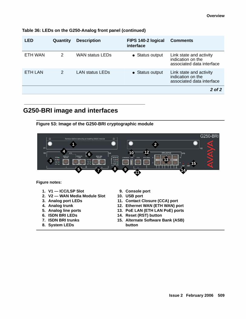
Overview
Issue 2 February 2006 509
G250-BRI image and interfaces
Figure 53: Image of the G250-BRI cryptographic module
ETH WAN 2 WAN status LEDs ● Status output Link state and activity indication on the associated data interface
ETH LAN 2 LAN status LEDs ● Status output Link state and activity indication on the associated data interface
Table 36: LEDs on the G250-Analog front panel (continued)
LED Quantity Description FIPS 140-2 logical interface
Comments
2 of 2
Figure notes:
1. V1 — ICC/LSP Slot2. V2 — WAN Media Module Slot3. Analog port LEDs4. Analog trunk5. Analog line ports6. ISDN BRI LEDs7. ISDN BRI trunks8. System LEDs
9. Console port10. USB port11. Contact Closure (CCA) port12. Ethernet WAN (ETH WAN) port13. PoE LAN (ETH LAN PoE) ports14. Reset (RST) button15. Alternate Software Bank (ASB)
button
7
12
13
14
1 2
3
4
5
6
8 9
10
11
15
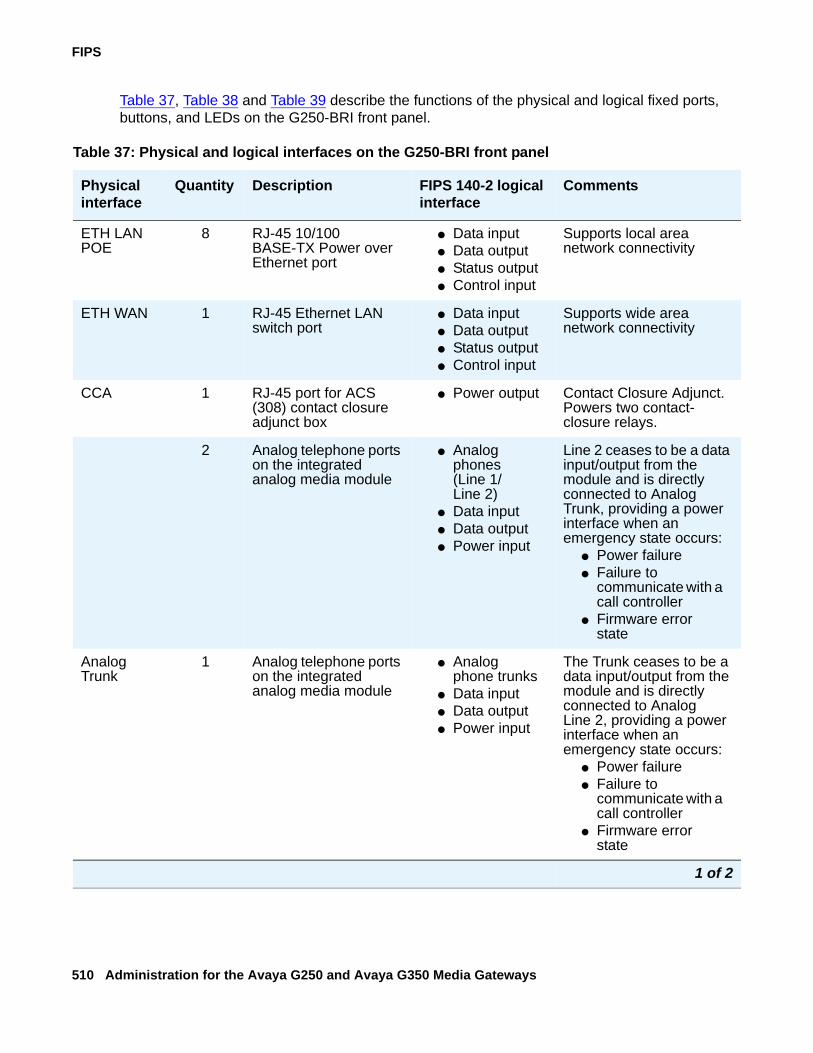
FIPS
510 Administration for the Avaya G250 and Avaya G350 Media Gateways
Table 37, Table 38 and Table 39 describe the functions of the physical and logical fixed ports, buttons, and LEDs on the G250-BRI front panel.
Table 37: Physical and logical interfaces on the G250-BRI front panel
Physical interface
Quantity Description FIPS 140-2 logical interface
Comments
ETH LAN POE
8 RJ-45 10/100 BASE-TX Power over Ethernet port
● Data input● Data output● Status output● Control input
Supports local area network connectivity
ETH WAN 1 RJ-45 Ethernet LAN switch port
● Data input● Data output● Status output● Control input
Supports wide area network connectivity
CCA 1 RJ-45 port for ACS (308) contact closure adjunct box
● Power output Contact Closure Adjunct. Powers two contact-closure relays.
2 Analog telephone ports on the integrated analog media module
● Analog phones(Line 1/Line 2)
● Data input● Data output● Power input
Line 2 ceases to be a data input/output from the module and is directly connected to Analog Trunk, providing a power interface when an emergency state occurs:
● Power failure● Failure to
communicate with a call controller
● Firmware error state
Analog Trunk
1 Analog telephone ports on the integrated analog media module
● Analog phone trunks
● Data input● Data output● Power input
The Trunk ceases to be a data input/output from the module and is directly connected to Analog Line 2, providing a power interface when an emergency state occurs:
● Power failure● Failure to
communicate with a call controller
● Firmware error state
1 of 2
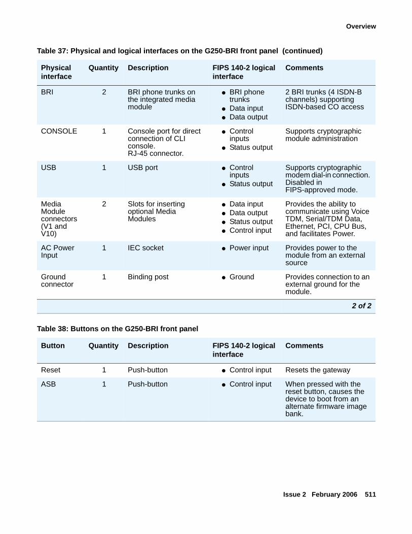
Overview
Issue 2 February 2006 511
BRI 2 BRI phone trunks on the integrated media module
● BRI phone trunks
● Data input● Data output
2 BRI trunks (4 ISDN-B channels) supporting ISDN-based CO access
CONSOLE 1 Console port for direct connection of CLI console.RJ-45 connector.
● Control inputs
● Status output
Supports cryptographic module administration
USB 1 USB port ● Control inputs
● Status output
Supports cryptographic modem dial-in connection. Disabled in FIPS-approved mode.
Media Module connectors (V1 and V10)
2 Slots for inserting optional Media Modules
● Data input● Data output● Status output● Control input
Provides the ability to communicate using Voice TDM, Serial/TDM Data, Ethernet, PCI, CPU Bus, and facilitates Power.
AC Power Input
1 IEC socket ● Power input Provides power to the module from an external source
Ground connector
1 Binding post ● Ground Provides connection to an external ground for the module.
Table 37: Physical and logical interfaces on the G250-BRI front panel (continued)
Physical interface
Quantity Description FIPS 140-2 logical interface
Comments
2 of 2
Table 38: Buttons on the G250-BRI front panel
Button Quantity Description FIPS 140-2 logical interface
Comments
Reset 1 Push-button ● Control input Resets the gateway
ASB 1 Push-button ● Control input When pressed with the reset button, causes the device to boot from an alternate firmware image bank.
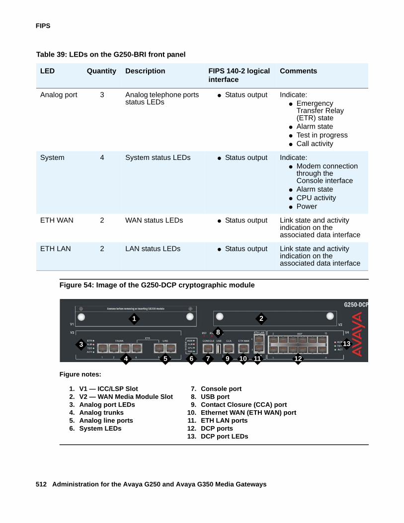
FIPS
512 Administration for the Avaya G250 and Avaya G350 Media Gateways
Figure 54: Image of the G250-DCP cryptographic module
Table 39: LEDs on the G250-BRI front panel
LED Quantity Description FIPS 140-2 logical interface
Comments
Analog port 3 Analog telephone ports status LEDs
● Status output Indicate:● Emergency
Transfer Relay (ETR) state
● Alarm state● Test in progress● Call activity
System 4 System status LEDs ● Status output Indicate:● Modem connection
through the Console interface
● Alarm state● CPU activity● Power
ETH WAN 2 WAN status LEDs ● Status output Link state and activity indication on the associated data interface
ETH LAN 2 LAN status LEDs ● Status output Link state and activity indication on the associated data interface
Figure notes:
1. V1 — ICC/LSP Slot2. V2 — WAN Media Module Slot3. Analog port LEDs4. Analog trunks5. Analog line ports6. System LEDs
7. Console port8. USB port9. Contact Closure (CCA) port
10. Ethernet WAN (ETH WAN) port11. ETH LAN ports12. DCP ports13. DCP port LEDs
7 12
13
1 2
3
4 5 6
8
9 10 11
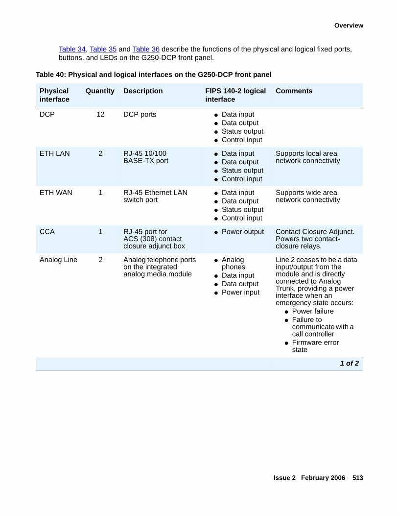
Overview
Issue 2 February 2006 513
Table 34, Table 35 and Table 36 describe the functions of the physical and logical fixed ports, buttons, and LEDs on the G250-DCP front panel.
Table 40: Physical and logical interfaces on the G250-DCP front panel
Physical interface
Quantity Description FIPS 140-2 logical interface
Comments
DCP 12 DCP ports ● Data input● Data output● Status output● Control input
ETH LAN 2 RJ-45 10/100 BASE-TX port
● Data input● Data output● Status output● Control input
Supports local area network connectivity
ETH WAN 1 RJ-45 Ethernet LAN switch port
● Data input● Data output● Status output● Control input
Supports wide area network connectivity
CCA 1 RJ-45 port for ACS (308) contact closure adjunct box
● Power output Contact Closure Adjunct. Powers two contact-closure relays.
Analog Line 2 Analog telephone ports on the integrated analog media module
● Analog phones
● Data input● Data output● Power input
Line 2 ceases to be a data input/output from the module and is directly connected to Analog Trunk, providing a power interface when an emergency state occurs:
● Power failure● Failure to
communicate with a call controller
● Firmware error state
1 of 2
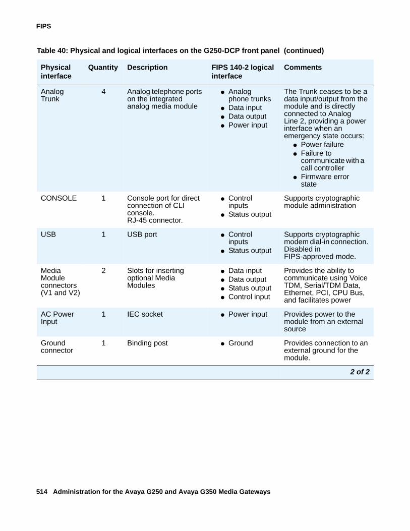
FIPS
514 Administration for the Avaya G250 and Avaya G350 Media Gateways
Analog Trunk
4 Analog telephone ports on the integrated analog media module
● Analog phone trunks
● Data input● Data output● Power input
The Trunk ceases to be a data input/output from the module and is directly connected to Analog Line 2, providing a power interface when an emergency state occurs:
● Power failure● Failure to
communicate with a call controller
● Firmware error state
CONSOLE 1 Console port for direct connection of CLI console.RJ-45 connector.
● Control inputs
● Status output
Supports cryptographic module administration
USB 1 USB port ● Control inputs
● Status output
Supports cryptographic modem dial-in connection. Disabled in FIPS-approved mode.
Media Module connectors (V1 and V2)
2 Slots for inserting optional Media Modules
● Data input● Data output● Status output● Control input
Provides the ability to communicate using Voice TDM, Serial/TDM Data, Ethernet, PCI, CPU Bus, and facilitates power
AC Power Input
1 IEC socket ● Power input Provides power to the module from an external source
Ground connector
1 Binding post ● Ground Provides connection to an external ground for the module.
Table 40: Physical and logical interfaces on the G250-DCP front panel (continued)
Physical interface
Quantity Description FIPS 140-2 logical interface
Comments
2 of 2
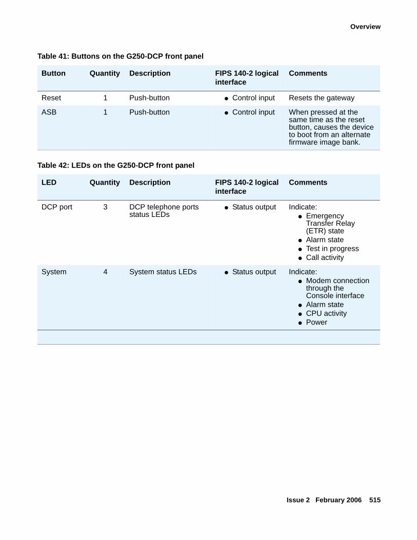
Overview
Issue 2 February 2006 515
Table 41: Buttons on the G250-DCP front panel
Button Quantity Description FIPS 140-2 logical interface
Comments
Reset 1 Push-button ● Control input Resets the gateway
ASB 1 Push-button ● Control input When pressed at the same time as the reset button, causes the device to boot from an alternate firmware image bank.
Table 42: LEDs on the G250-DCP front panel
LED Quantity Description FIPS 140-2 logical interface
Comments
DCP port 3 DCP telephone ports status LEDs
● Status output Indicate:● Emergency
Transfer Relay (ETR) state
● Alarm state● Test in progress● Call activity
System 4 System status LEDs ● Status output Indicate:● Modem connection
through the Console interface
● Alarm state● CPU activity● Power
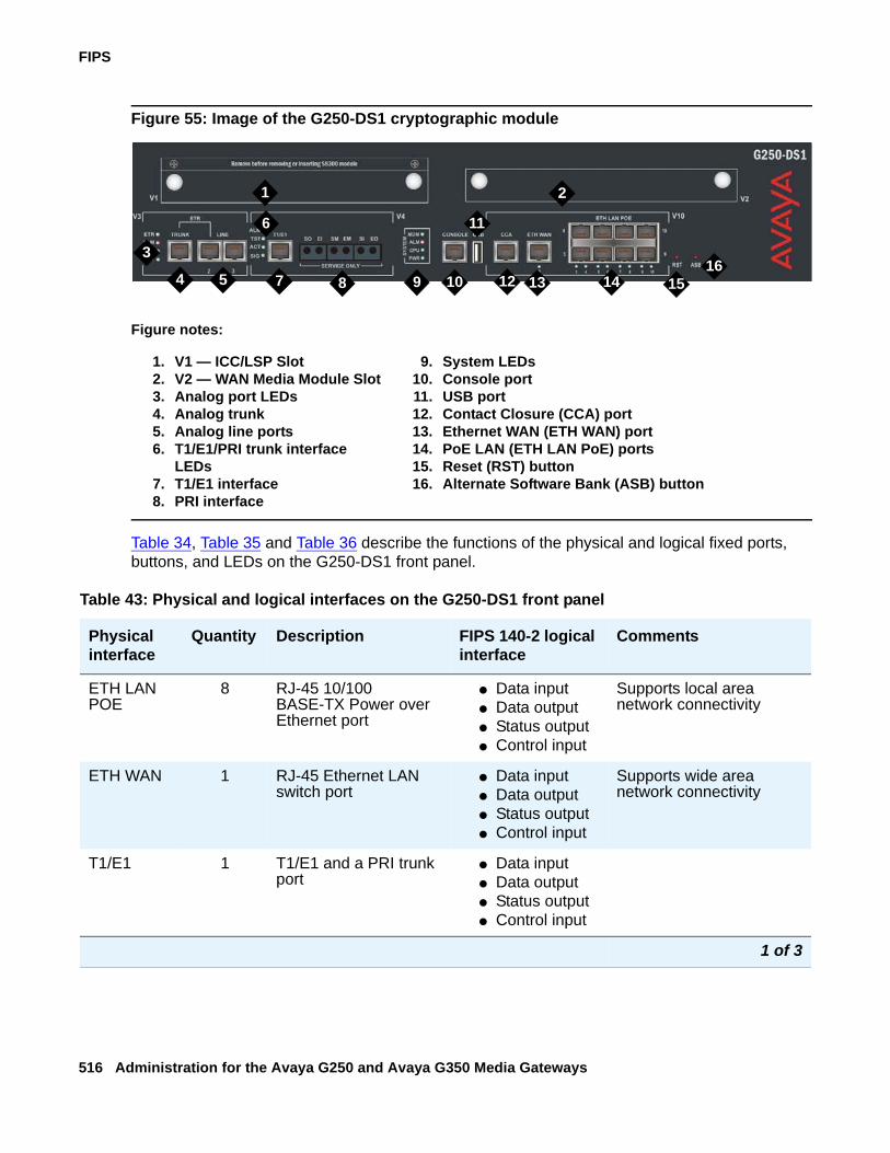
FIPS
516 Administration for the Avaya G250 and Avaya G350 Media Gateways
Figure 55: Image of the G250-DS1 cryptographic module
Table 34, Table 35 and Table 36 describe the functions of the physical and logical fixed ports, buttons, and LEDs on the G250-DS1 front panel.
Figure notes:
1. V1 — ICC/LSP Slot2. V2 — WAN Media Module Slot3. Analog port LEDs4. Analog trunk5. Analog line ports6. T1/E1/PRI trunk interface
LEDs7. T1/E1 interface8. PRI interface
9. System LEDs10. Console port11. USB port12. Contact Closure (CCA) port13. Ethernet WAN (ETH WAN) port14. PoE LAN (ETH LAN PoE) ports15. Reset (RST) button16. Alternate Software Bank (ASB) button
7 12 13 14
1 2
3
4 5
6
8 9 10
11
1516
Table 43: Physical and logical interfaces on the G250-DS1 front panel
Physical interface
Quantity Description FIPS 140-2 logical interface
Comments
ETH LAN POE
8 RJ-45 10/100 BASE-TX Power over Ethernet port
● Data input● Data output● Status output● Control input
Supports local area network connectivity
ETH WAN 1 RJ-45 Ethernet LAN switch port
● Data input● Data output● Status output● Control input
Supports wide area network connectivity
T1/E1 1 T1/E1 and a PRI trunk port
● Data input● Data output● Status output● Control input
1 of 3
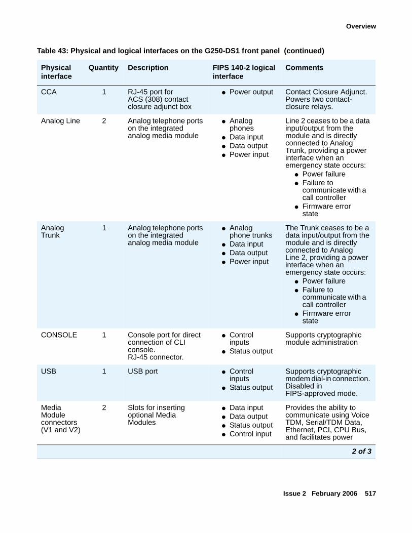
Overview
Issue 2 February 2006 517
CCA 1 RJ-45 port for ACS (308) contact closure adjunct box
● Power output Contact Closure Adjunct. Powers two contact-closure relays.
Analog Line 2 Analog telephone ports on the integrated analog media module
● Analog phones
● Data input● Data output● Power input
Line 2 ceases to be a data input/output from the module and is directly connected to Analog Trunk, providing a power interface when an emergency state occurs:
● Power failure● Failure to
communicate with a call controller
● Firmware error state
Analog Trunk
1 Analog telephone ports on the integrated analog media module
● Analog phone trunks
● Data input● Data output● Power input
The Trunk ceases to be a data input/output from the module and is directly connected to Analog Line 2, providing a power interface when an emergency state occurs:
● Power failure● Failure to
communicate with a call controller
● Firmware error state
CONSOLE 1 Console port for direct connection of CLI console.RJ-45 connector.
● Control inputs
● Status output
Supports cryptographic module administration
USB 1 USB port ● Control inputs
● Status output
Supports cryptographic modem dial-in connection. Disabled in FIPS-approved mode.
Media Module connectors (V1 and V2)
2 Slots for inserting optional Media Modules
● Data input● Data output● Status output● Control input
Provides the ability to communicate using Voice TDM, Serial/TDM Data, Ethernet, PCI, CPU Bus, and facilitates power
Table 43: Physical and logical interfaces on the G250-DS1 front panel (continued)
Physical interface
Quantity Description FIPS 140-2 logical interface
Comments
2 of 3
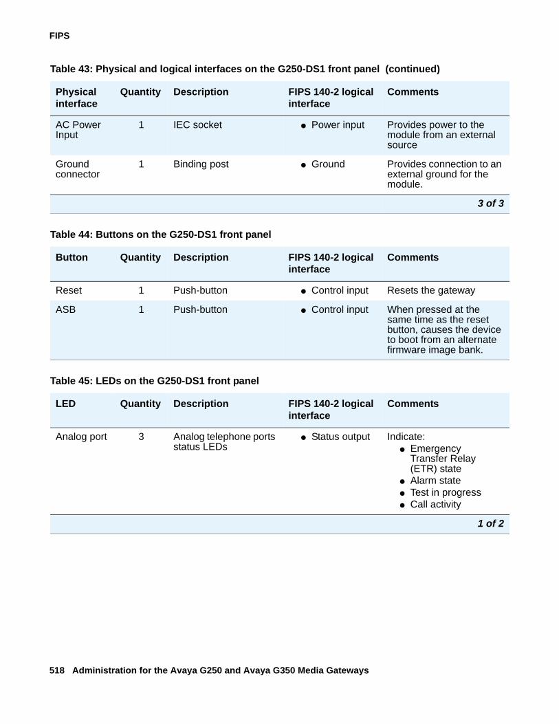
FIPS
518 Administration for the Avaya G250 and Avaya G350 Media Gateways
AC Power Input
1 IEC socket ● Power input Provides power to the module from an external source
Ground connector
1 Binding post ● Ground Provides connection to an external ground for the module.
Table 43: Physical and logical interfaces on the G250-DS1 front panel (continued)
Physical interface
Quantity Description FIPS 140-2 logical interface
Comments
3 of 3
Table 44: Buttons on the G250-DS1 front panel
Button Quantity Description FIPS 140-2 logical interface
Comments
Reset 1 Push-button ● Control input Resets the gateway
ASB 1 Push-button ● Control input When pressed at the same time as the reset button, causes the device to boot from an alternate firmware image bank.
Table 45: LEDs on the G250-DS1 front panel
LED Quantity Description FIPS 140-2 logical interface
Comments
Analog port 3 Analog telephone ports status LEDs
● Status output Indicate:● Emergency
Transfer Relay (ETR) state
● Alarm state● Test in progress● Call activity
1 of 2
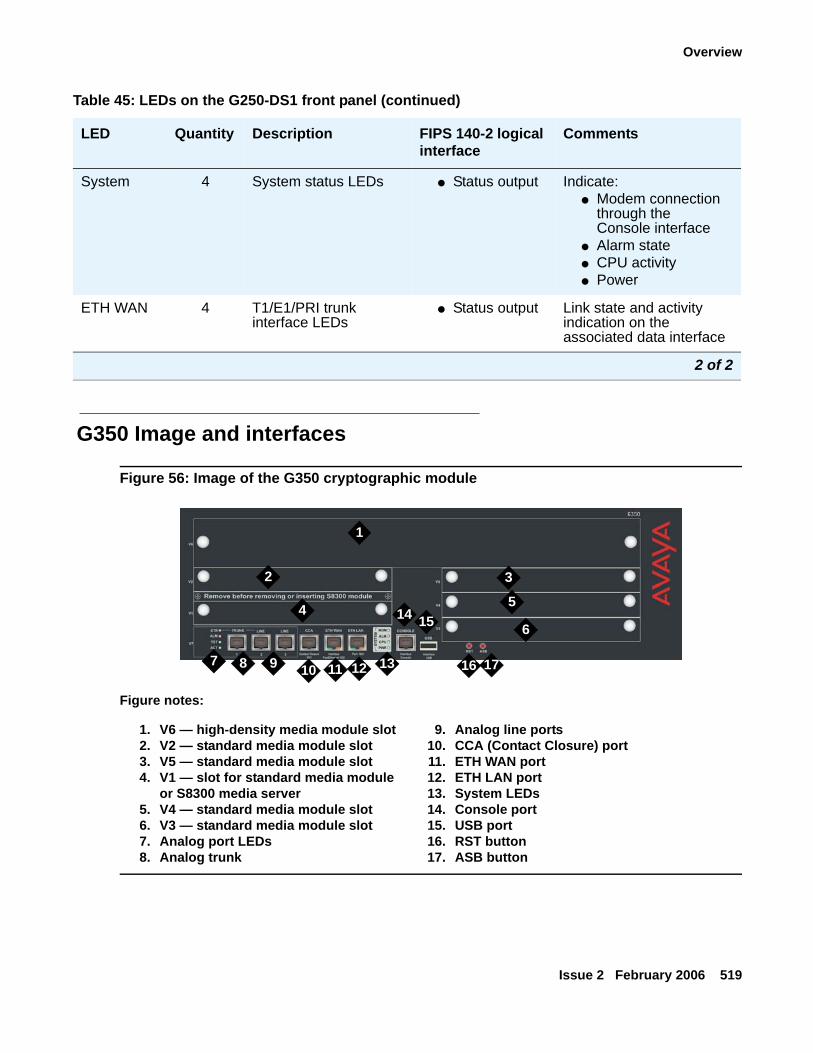
Overview
Issue 2 February 2006 519
G350 Image and interfaces
Figure 56: Image of the G350 cryptographic module
System 4 System status LEDs ● Status output Indicate:● Modem connection
through the Console interface
● Alarm state● CPU activity● Power
ETH WAN 4 T1/E1/PRI trunk interface LEDs
● Status output Link state and activity indication on the associated data interface
Table 45: LEDs on the G250-DS1 front panel (continued)
LED Quantity Description FIPS 140-2 logical interface
Comments
2 of 2
Figure notes:
1. V6 — high-density media module slot2. V2 — standard media module slot3. V5 — standard media module slot4. V1 — slot for standard media module
or S8300 media server5. V4 — standard media module slot6. V3 — standard media module slot7. Analog port LEDs8. Analog trunk
9. Analog line ports10. CCA (Contact Closure) port11. ETH WAN port12. ETH LAN port13. System LEDs14. Console port15. USB port16. RST button17. ASB button
1
2 3
4 5
6
7 8 9 10 11 12 13
14 15
16 17
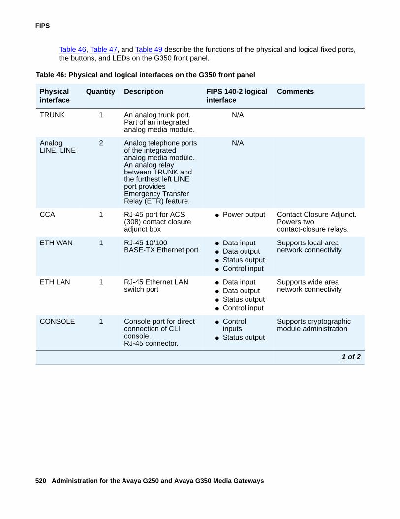
FIPS
520 Administration for the Avaya G250 and Avaya G350 Media Gateways
Table 46, Table 47, and Table 49 describe the functions of the physical and logical fixed ports, the buttons, and LEDs on the G350 front panel.
Table 46: Physical and logical interfaces on the G350 front panel
Physical interface
Quantity Description FIPS 140-2 logical interface
Comments
TRUNK 1 An analog trunk port. Part of an integrated analog media module.
N/A
Analog LINE, LINE
2 Analog telephone ports of the integrated analog media module. An analog relay between TRUNK and the furthest left LINE port provides Emergency Transfer Relay (ETR) feature.
N/A
CCA 1 RJ-45 port for ACS (308) contact closure adjunct box
● Power output Contact Closure Adjunct. Powers two contact-closure relays.
ETH WAN 1 RJ-45 10/100 BASE-TX Ethernet port
● Data input● Data output● Status output● Control input
Supports local area network connectivity
ETH LAN 1 RJ-45 Ethernet LAN switch port
● Data input● Data output● Status output● Control input
Supports wide area network connectivity
CONSOLE 1 Console port for direct connection of CLI console.RJ-45 connector.
● Control inputs
● Status output
Supports cryptographic module administration
1 of 2
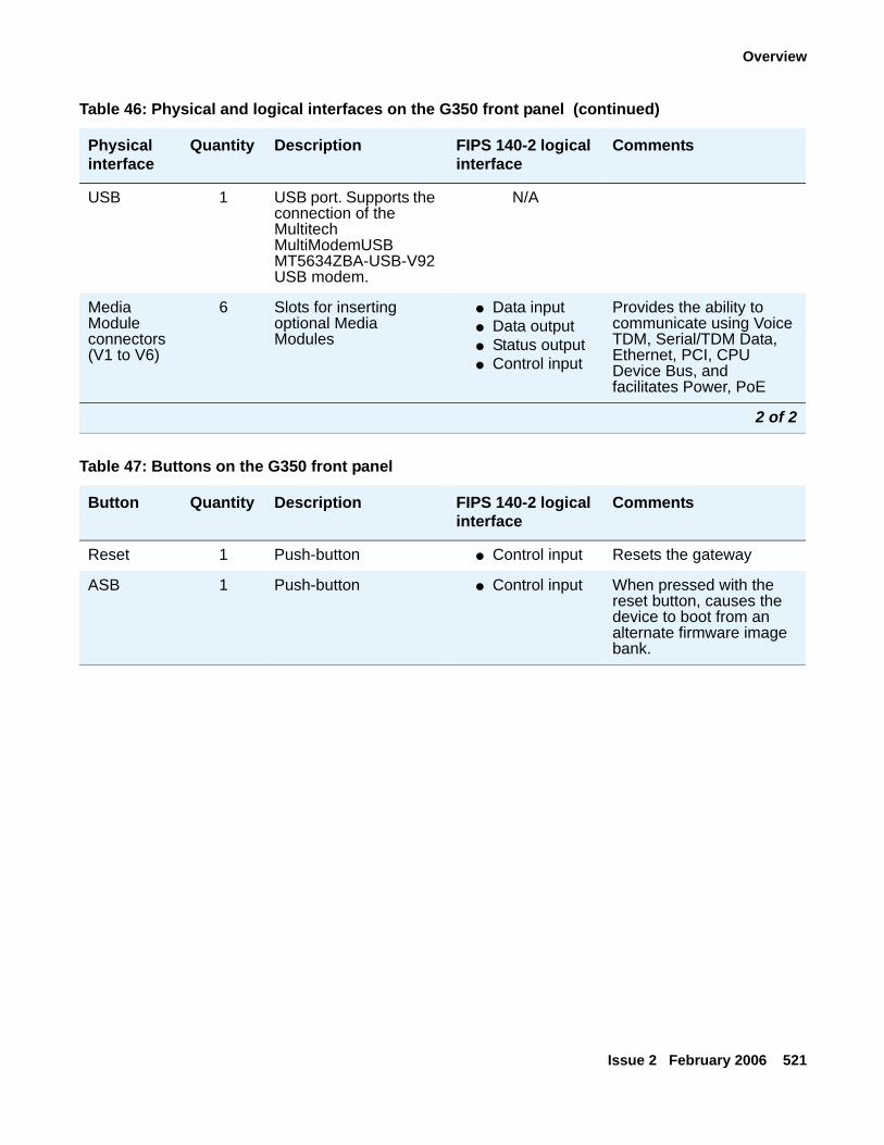
Overview
Issue 2 February 2006 521
USB 1 USB port. Supports the connection of the Multitech MultiModemUSB MT5634ZBA-USB-V92 USB modem.
N/A
Media Module connectors (V1 to V6)
6 Slots for inserting optional Media Modules
● Data input● Data output● Status output● Control input
Provides the ability to communicate using Voice TDM, Serial/TDM Data, Ethernet, PCI, CPU Device Bus, and facilitates Power, PoE
Table 46: Physical and logical interfaces on the G350 front panel (continued)
Physical interface
Quantity Description FIPS 140-2 logical interface
Comments
2 of 2
Table 47: Buttons on the G350 front panel
Button Quantity Description FIPS 140-2 logical interface
Comments
Reset 1 Push-button ● Control input Resets the gateway
ASB 1 Push-button ● Control input When pressed with the reset button, causes the device to boot from an alternate firmware image bank.
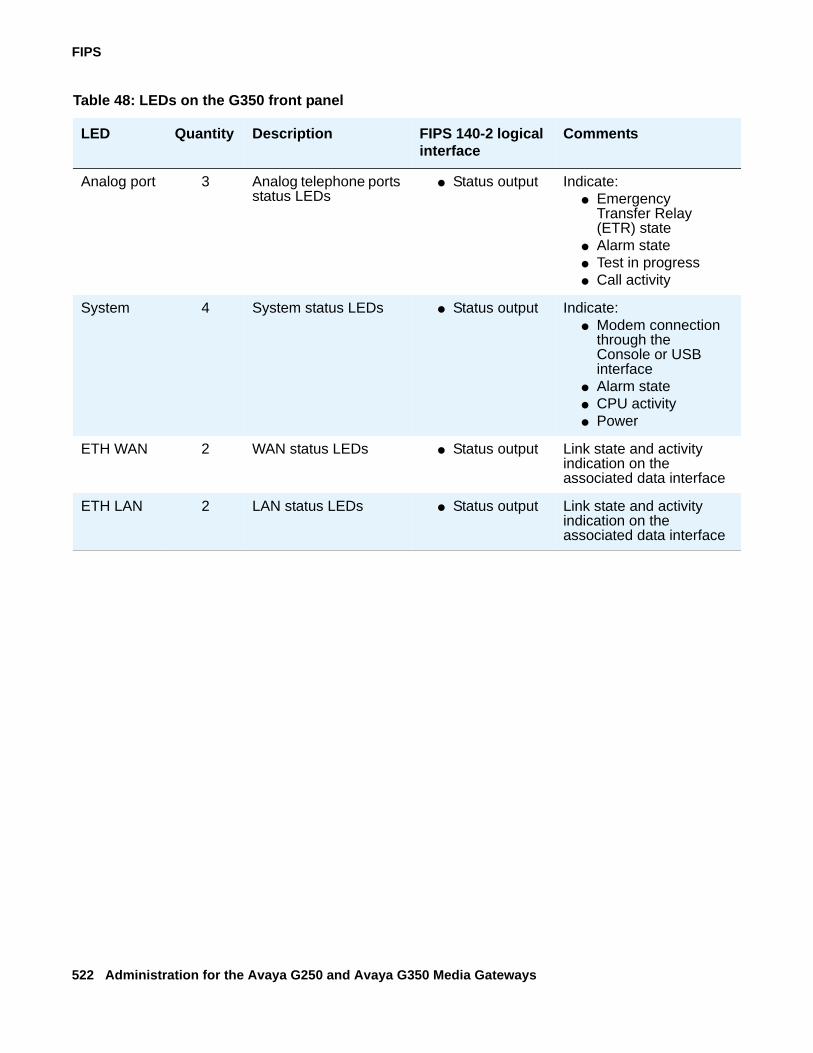
FIPS
522 Administration for the Avaya G250 and Avaya G350 Media Gateways
Table 48: LEDs on the G350 front panel
LED Quantity Description FIPS 140-2 logical interface
Comments
Analog port 3 Analog telephone ports status LEDs
● Status output Indicate:● Emergency
Transfer Relay (ETR) state
● Alarm state● Test in progress● Call activity
System 4 System status LEDs ● Status output Indicate:● Modem connection
through the Console or USB interface
● Alarm state● CPU activity● Power
ETH WAN 2 WAN status LEDs ● Status output Link state and activity indication on the associated data interface
ETH LAN 2 LAN status LEDs ● Status output Link state and activity indication on the associated data interface
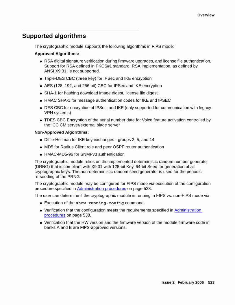
Overview
Issue 2 February 2006 523
Supported algorithmsThe cryptographic module supports the following algorithms in FIPS mode:
Approved Algorithms:● RSA digital signature verification during firmware upgrades, and license file authentication.
Support for RSA defined in PKCS#1 standard. RSA implementation, as defined by ANSI X9.31, is not supported.
● Triple-DES CBC (three key) for IPSec and IKE encryption
● AES (128, 192, and 256 bit) CBC for IPSec and IKE encryption
● SHA-1 for hashing download image digest, license file digest
● HMAC SHA-1 for message authentication codes for IKE and IPSEC
● DES CBC for encryption of IPSec, and IKE (only supported for communication with legacy VPN systems)
● TDES CBC Encryption of the serial number date for Voice feature activation controlled by the ICC CM server/external blade server
Non-Approved Algorithms:● Diffie-Hellman for IKE key exchanges - groups 2, 5, and 14
● MD5 for Radius Client role and peer OSPF router authentication
● HMAC-MD5-96 for SNMPv3 authentication
The cryptographic module relies on the implemented deterministic random number generator (DRNG) that is compliant with X9.31 with 128-bit Key, 64-bit Seed for generation of all cryptographic keys. The non-deterministic random seed generator is used for the periodic re-seeding of the PRNG. The cryptographic module may be configured for FIPS mode via execution of the configuration procedure specified in Administration procedures on page 538.The user can determine if the cryptographic module is running in FIPS vs. non-FIPS mode via:
● Execution of the show running-config command.
● Verification that the configuration meets the requirements specified in Administration procedures on page 538.
● Verification that the HW version and the firmware version of the module firmware code in banks A and B are FIPS-approved versions.
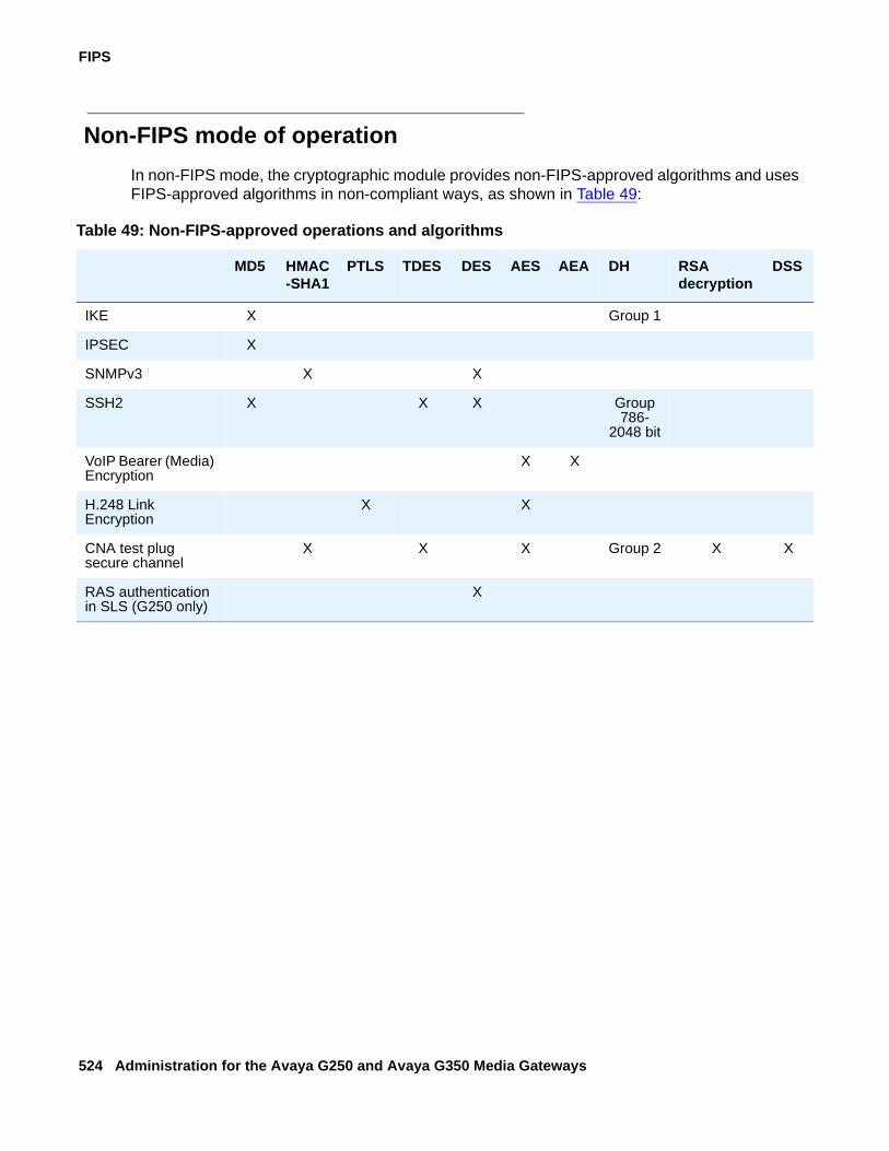
FIPS
524 Administration for the Avaya G250 and Avaya G350 Media Gateways
Non-FIPS mode of operationIn non-FIPS mode, the cryptographic module provides non-FIPS-approved algorithms and uses FIPS-approved algorithms in non-compliant ways, as shown in Table 49:
Table 49: Non-FIPS-approved operations and algorithms
MD5 HMAC-SHA1
PTLS TDES DES AES AEA DH RSA decryption
DSS
IKE X Group 1
IPSEC X
SNMPv3 X X
SSH2 X X X Group 786-
2048 bit
VoIP Bearer (Media) Encryption
X X
H.248 Link Encryption
X X
CNA test plug secure channel
X X X Group 2 X X
RAS authentication in SLS (G250 only)
X
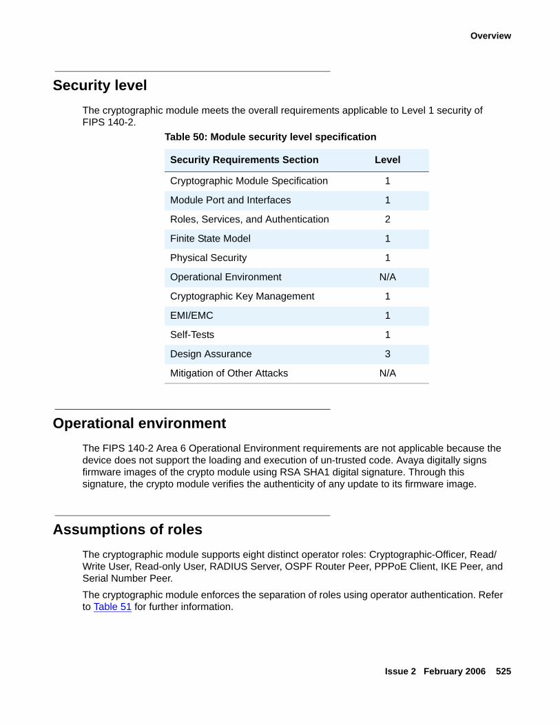
Overview
Issue 2 February 2006 525
Security levelThe cryptographic module meets the overall requirements applicable to Level 1 security of FIPS 140-2.
Operational environmentThe FIPS 140-2 Area 6 Operational Environment requirements are not applicable because the device does not support the loading and execution of un-trusted code. Avaya digitally signs firmware images of the crypto module using RSA SHA1 digital signature. Through this signature, the crypto module verifies the authenticity of any update to its firmware image.
Assumptions of rolesThe cryptographic module supports eight distinct operator roles: Cryptographic-Officer, Read/Write User, Read-only User, RADIUS Server, OSPF Router Peer, PPPoE Client, IKE Peer, and Serial Number Peer.The cryptographic module enforces the separation of roles using operator authentication. Refer to Table 51 for further information.
Table 50: Module security level specification
Security Requirements Section Level
Cryptographic Module Specification 1
Module Port and Interfaces 1
Roles, Services, and Authentication 2
Finite State Model 1
Physical Security 1
Operational Environment N/A
Cryptographic Key Management 1
EMI/EMC 1
Self-Tests 1
Design Assurance 3
Mitigation of Other Attacks N/A
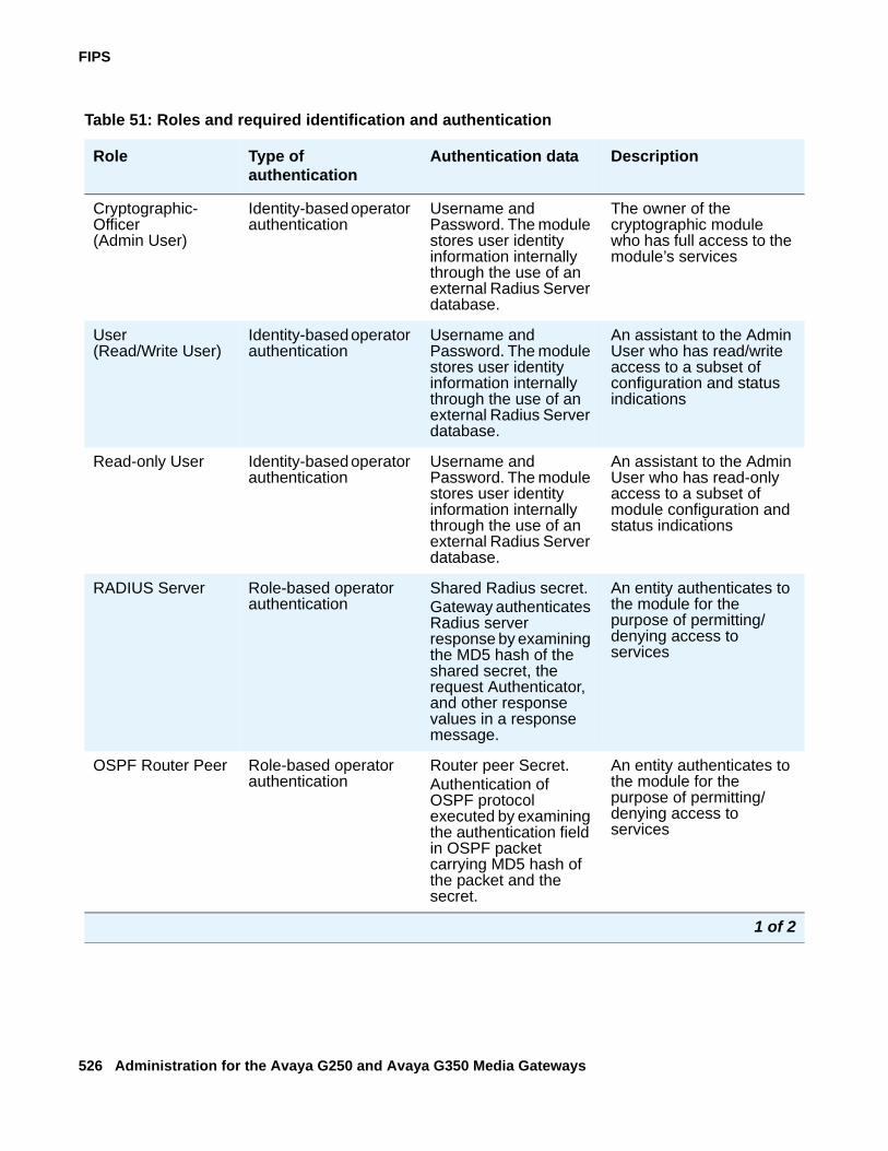
FIPS
526 Administration for the Avaya G250 and Avaya G350 Media Gateways
Table 51: Roles and required identification and authentication
Role Type of authentication
Authentication data Description
Cryptographic-Officer (Admin User)
Identity-based operator authentication
Username and Password. The module stores user identity information internally through the use of an external Radius Server database.
The owner of the cryptographic module who has full access to the module’s services
User (Read/Write User)
Identity-based operator authentication
Username and Password. The module stores user identity information internally through the use of an external Radius Server database.
An assistant to the Admin User who has read/write access to a subset of configuration and status indications
Read-only User Identity-based operator authentication
Username and Password. The module stores user identity information internally through the use of an external Radius Server database.
An assistant to the Admin User who has read-only access to a subset of module configuration and status indications
RADIUS Server Role-based operator authentication
Shared Radius secret.Gateway authenticates Radius server response by examining the MD5 hash of the shared secret, the request Authenticator, and other response values in a response message.
An entity authenticates to the module for the purpose of permitting/denying access to services
OSPF Router Peer Role-based operator authentication
Router peer Secret.Authentication of OSPF protocol executed by examining the authentication field in OSPF packet carrying MD5 hash of the packet and the secret.
An entity authenticates to the module for the purpose of permitting/denying access to services
1 of 2
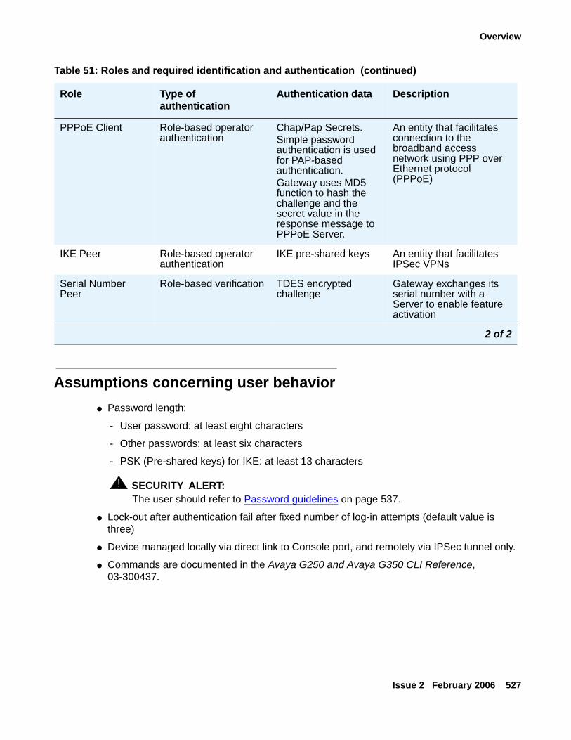
Overview
Issue 2 February 2006 527
Assumptions concerning user behavior● Password length:
- User password: at least eight characters
- Other passwords: at least six characters
- PSK (Pre-shared keys) for IKE: at least 13 characters
! SECURITY ALERT:SECURITY ALERT: The user should refer to Password guidelines on page 537.
● Lock-out after authentication fail after fixed number of log-in attempts (default value is three)
● Device managed locally via direct link to Console port, and remotely via IPSec tunnel only.
● Commands are documented in the Avaya G250 and Avaya G350 CLI Reference, 03-300437.
PPPoE Client Role-based operator authentication
Chap/Pap Secrets.Simple password authentication is used for PAP-based authentication. Gateway uses MD5 function to hash the challenge and the secret value in the response message to PPPoE Server.
An entity that facilitates connection to the broadband access network using PPP over Ethernet protocol (PPPoE)
IKE Peer Role-based operator authentication
IKE pre-shared keys An entity that facilitates IPSec VPNs
Serial Number Peer
Role-based verification TDES encrypted challenge
Gateway exchanges its serial number with a Server to enable feature activation
Table 51: Roles and required identification and authentication (continued)
Role Type of authentication
Authentication data Description
2 of 2
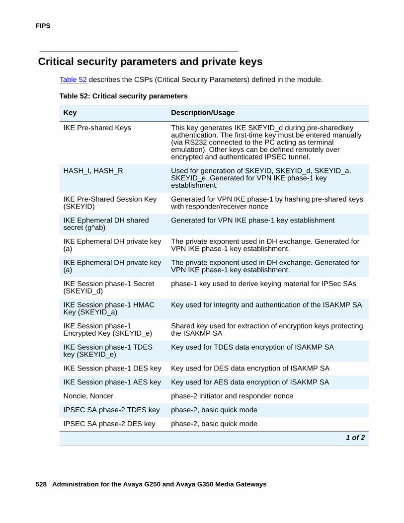
FIPS
528 Administration for the Avaya G250 and Avaya G350 Media Gateways
Critical security parameters and private keysTable 52 describes the CSPs (Critical Security Parameters) defined in the module.
Table 52: Critical security parameters
Key Description/Usage
IKE Pre-shared Keys This key generates IKE SKEYID_d during pre-sharedkey authentication. The first-time key must be entered manually (via RS232 connected to the PC acting as terminal emulation). Other keys can be defined remotely over encrypted and authenticated IPSEC tunnel.
HASH_I, HASH_R Used for generation of SKEYID, SKEYID_d, SKEYID_a, SKEYID_e. Generated for VPN IKE phase-1 key establishment.
IKE Pre-Shared Session Key (SKEYID)
Generated for VPN IKE phase-1 by hashing pre-shared keys with responder/receiver nonce
IKE Ephemeral DH shared secret (g^ab)
Generated for VPN IKE phase-1 key establishment
IKE Ephemeral DH private key (a)
The private exponent used in DH exchange. Generated for VPN IKE phase-1 key establishment.
IKE Ephemeral DH private key (a)
The private exponent used in DH exchange. Generated for VPN IKE phase-1 key establishment.
IKE Session phase-1 Secret (SKEYID_d)
phase-1 key used to derive keying material for IPSec SAs
IKE Session phase-1 HMAC Key (SKEYID_a)
Key used for integrity and authentication of the ISAKMP SA
IKE Session phase-1 Encrypted Key (SKEYID_e)
Shared key used for extraction of encryption keys protecting the ISAKMP SA
IKE Session phase-1 TDES key (SKEYID_e)
Key used for TDES data encryption of ISAKMP SA
IKE Session phase-1 DES key Key used for DES data encryption of ISAKMP SA
IKE Session phase-1 AES key Key used for AES data encryption of ISAKMP SA
Noncie, Noncer phase-2 initiator and responder nonce
IPSEC SA phase-2 TDES key phase-2, basic quick mode
IPSEC SA phase-2 DES key phase-2, basic quick mode
1 of 2
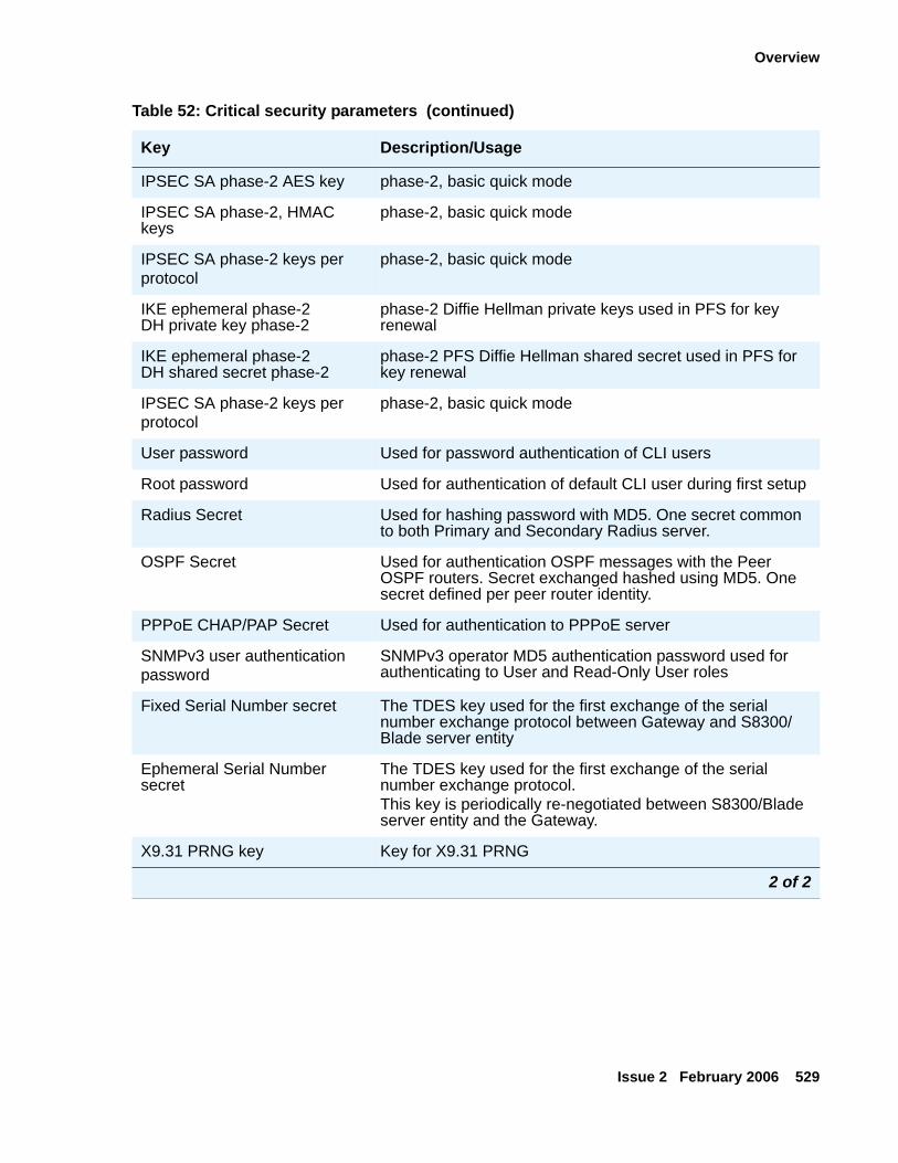
Overview
Issue 2 February 2006 529
IPSEC SA phase-2 AES key phase-2, basic quick mode
IPSEC SA phase-2, HMAC keys
phase-2, basic quick mode
IPSEC SA phase-2 keys perprotocol
phase-2, basic quick mode
IKE ephemeral phase-2 DH private key phase-2
phase-2 Diffie Hellman private keys used in PFS for key renewal
IKE ephemeral phase-2 DH shared secret phase-2
phase-2 PFS Diffie Hellman shared secret used in PFS for key renewal
IPSEC SA phase-2 keys perprotocol
phase-2, basic quick mode
User password Used for password authentication of CLI users
Root password Used for authentication of default CLI user during first setup
Radius Secret Used for hashing password with MD5. One secret common to both Primary and Secondary Radius server.
OSPF Secret Used for authentication OSPF messages with the Peer OSPF routers. Secret exchanged hashed using MD5. One secret defined per peer router identity.
PPPoE CHAP/PAP Secret Used for authentication to PPPoE server
SNMPv3 user authenticationpassword
SNMPv3 operator MD5 authentication password used for authenticating to User and Read-Only User roles
Fixed Serial Number secret The TDES key used for the first exchange of the serial number exchange protocol between Gateway and S8300/Blade server entity
Ephemeral Serial Number secret
The TDES key used for the first exchange of the serial number exchange protocol.This key is periodically re-negotiated between S8300/Blade server entity and the Gateway.
X9.31 PRNG key Key for X9.31 PRNG
Table 52: Critical security parameters (continued)
Key Description/Usage
2 of 2
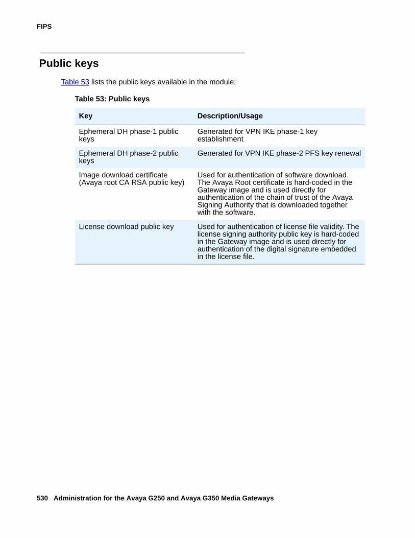
FIPS
530 Administration for the Avaya G250 and Avaya G350 Media Gateways
Public keysTable 53 lists the public keys available in the module:
Table 53: Public keys
Key Description/Usage
Ephemeral DH phase-1 public keys
Generated for VPN IKE phase-1 key establishment
Ephemeral DH phase-2 public keys
Generated for VPN IKE phase-2 PFS key renewal
Image download certificate (Avaya root CA RSA public key)
Used for authentication of software download. The Avaya Root certificate is hard-coded in the Gateway image and is used directly for authentication of the chain of trust of the Avaya Signing Authority that is downloaded together with the software.
License download public key Used for authentication of license file validity. The license signing authority public key is hard-coded in the Gateway image and is used directly for authentication of the digital signature embedded in the license file.
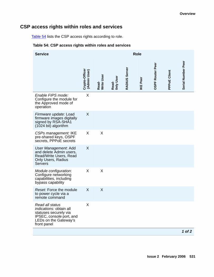
Overview
Issue 2 February 2006 531
CSP access rights within roles and services
Table 54 lists the CSP access rights according to role.
Table 54: CSP access rights within roles and services
Service Role
Cry
pto-
Offi
cer
(Adm
in U
ser)
Rea
d-W
rite
Use
r
Rea
d-0n
ly U
ser
RA
DIU
S Se
rver
IKE
Peer
OSP
F R
oute
r Pee
r
PPPo
E C
lient
Seria
l Num
ber P
eer
Enable FIPS mode: Configure the module for the Approved mode of operation
X
Firmware update: Load firmware images digitally signed by RSA-SHA1 (1024 bit) algorithm
X
CSPs management: IKE pre-shared keys, OSPF secrets, PPPoE secrets
X X
User Management: Add and delete Admin users, Read/Write Users, Read Only Users, Radius Servers
X
Module configuration: Configure networking capabilities, including bypass capability
X X
Reset: Force the module to power cycle via a remote command
X X
Read all status indications: obtain all statuses securely via IPSEC, console port, and LEDs on the Gateway’s front panel
X
1 of 2
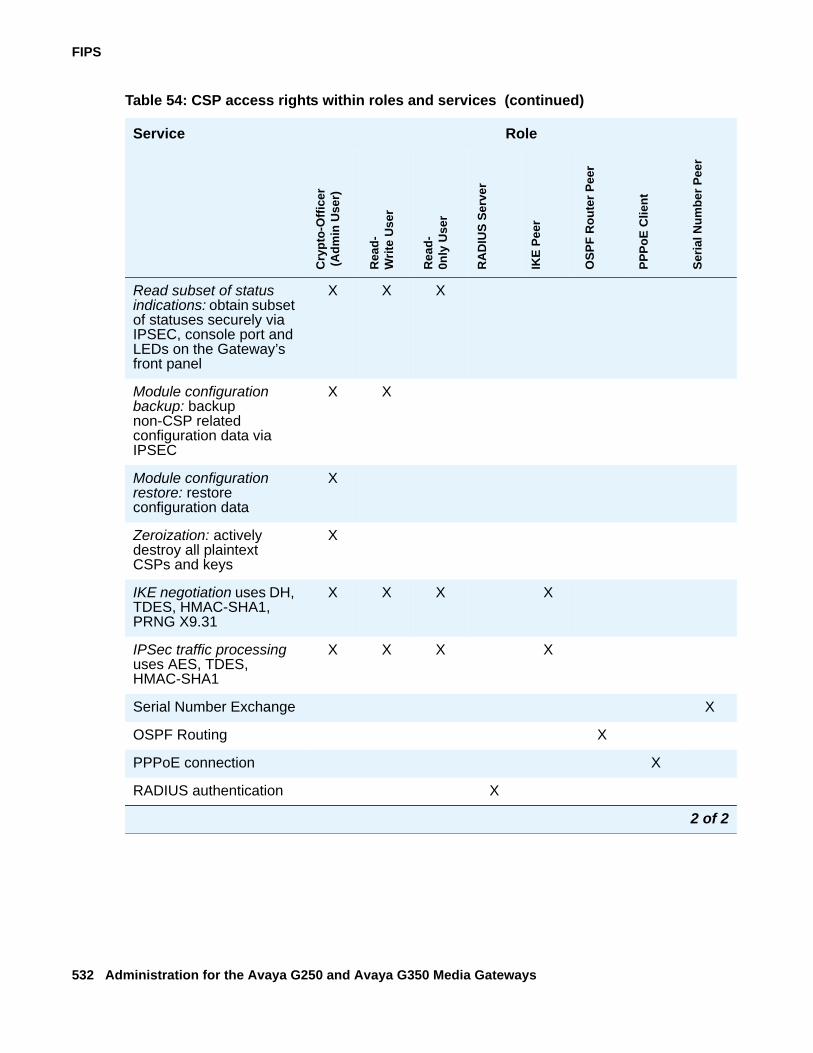
FIPS
532 Administration for the Avaya G250 and Avaya G350 Media Gateways
Read subset of status indications: obtain subset of statuses securely via IPSEC, console port and LEDs on the Gateway’s front panel
X X X
Module configuration backup: backup non-CSP related configuration data via IPSEC
X X
Module configuration restore: restore configuration data
X
Zeroization: actively destroy all plaintext CSPs and keys
X
IKE negotiation uses DH, TDES, HMAC-SHA1, PRNG X9.31
X X X X
IPSec traffic processing uses AES, TDES, HMAC-SHA1
X X X X
Serial Number Exchange X
OSPF Routing X
PPPoE connection X
RADIUS authentication X
Table 54: CSP access rights within roles and services (continued)
Service Role
Cry
pto-
Offi
cer
(Adm
in U
ser)
Rea
d-W
rite
Use
r
Rea
d-0n
ly U
ser
RA
DIU
S Se
rver
IKE
Peer
OSP
F R
oute
r Pee
r
PPPo
E C
lient
Seria
l Num
ber P
eer
2 of 2
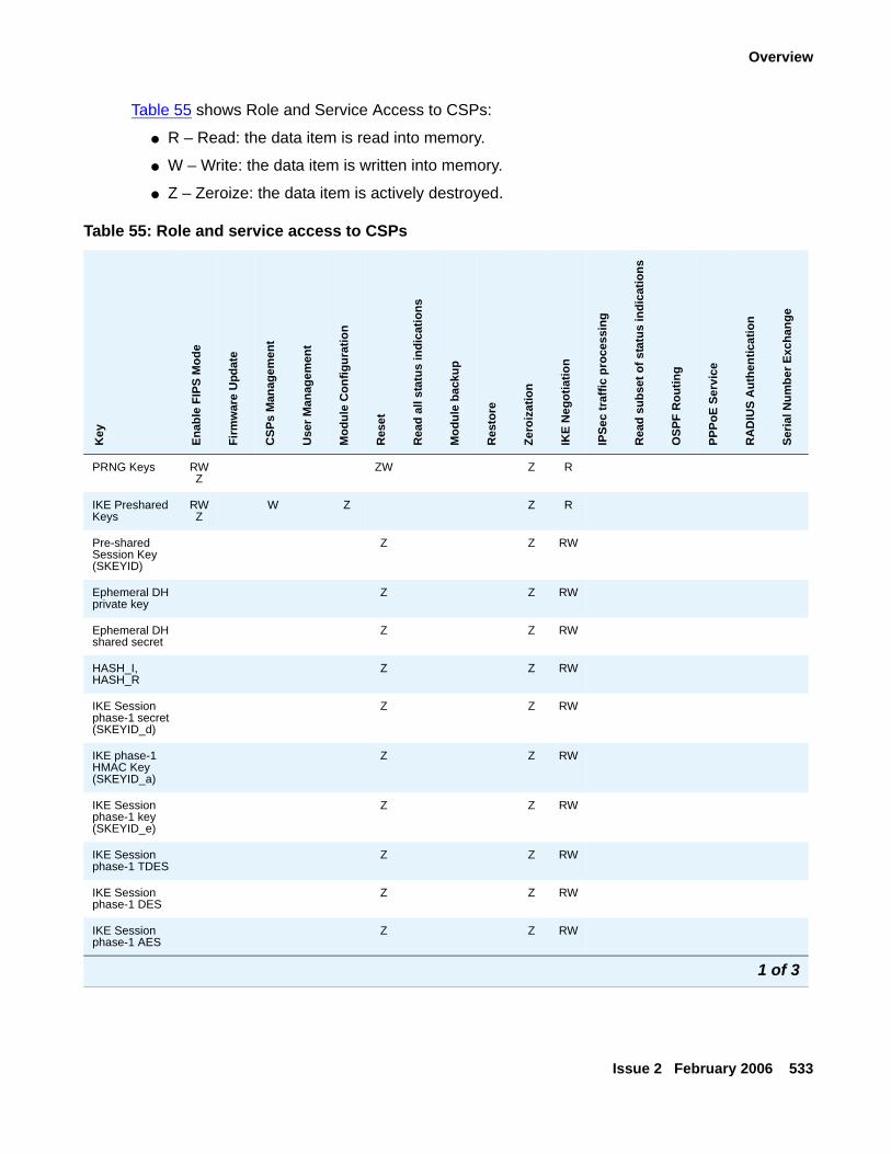
Overview
Issue 2 February 2006 533
Table 55 shows Role and Service Access to CSPs:
● R – Read: the data item is read into memory.
● W – Write: the data item is written into memory.
● Z – Zeroize: the data item is actively destroyed.
Table 55: Role and service access to CSPs
Key
Enab
le F
IPS
Mod
e
Firm
war
e U
pdat
e
CSP
s M
anag
emen
t
Use
r Man
agem
ent
Mod
ule
Con
figur
atio
n
Res
et
Rea
d al
l sta
tus
indi
catio
ns
Mod
ule
back
up
Res
tore
Zero
izat
ion
IKE
Neg
otia
tion
IPSe
c tr
affic
pro
cess
ing
Rea
d su
bset
of s
tatu
s in
dica
tions
OSP
F R
outin
g
PPPo
E Se
rvic
e
RA
DIU
S A
uthe
ntic
atio
n
Seria
l Num
ber E
xcha
nge
PRNG Keys RWZ
ZW Z R
IKE Preshared Keys
RWZ
W Z Z R
Pre-shared Session Key (SKEYID)
Z Z RW
Ephemeral DH private key
Z Z RW
Ephemeral DH shared secret
Z Z RW
HASH_I, HASH_R
Z Z RW
IKE Session phase-1 secret (SKEYID_d)
Z Z RW
IKE phase-1 HMAC Key (SKEYID_a)
Z Z RW
IKE Session phase-1 key (SKEYID_e)
Z Z RW
IKE Session phase-1 TDES
Z Z RW
IKE Session phase-1 DES
Z Z RW
IKE Session phase-1 AES
Z Z RW
1 of 3

FIPS
534 Administration for the Avaya G250 and Avaya G350 Media Gateways
IKE phase-1 TDES key (SKEYID-e)
Z Z RW
Nonce Z Z W R
IPSEC SA phase-2 TDES key
Z Z W R
IPSEC SA phase-2 AES key
WZ Z Z W R
IPSEC SA phase-2 HMAC keys
Z Z W R
IPSEC SA phase-2 keys per protocol
Z Z RW
Ephemeral DH phase-2 private key
Z Z RW
DH phase-2 shared secret
Z Z RW
User password WZ R R WZ R R R R R Z R
Root password RW RW R W R R R R R W R
OSPF Secret WZ WZ Z Z R
RADIUS Secret
WZ WZ Z R
PPPoE Chap/PAP Secret
WZ W Z Z R
SNMPv3 authentication password
WZ R R WZ R R R R R Z
Fixed Serial Number secret
W Z R
Table 55: Role and service access to CSPs (continued)K
ey
Enab
le F
IPS
Mod
e
Firm
war
e U
pdat
e
CSP
s M
anag
emen
t
Use
r Man
agem
ent
Mod
ule
Con
figur
atio
n
Res
et
Rea
d al
l sta
tus
indi
catio
ns
Mod
ule
back
up
Res
tore
Zero
izat
ion
IKE
Neg
otia
tion
IPSe
c tr
affic
pro
cess
ing
Rea
d su
bset
of s
tatu
s in
dica
tions
OSP
F R
outin
g
PPPo
E Se
rvic
e
RA
DIU
S A
uthe
ntic
atio
n
Seria
l Num
ber E
xcha
nge
2 of 3
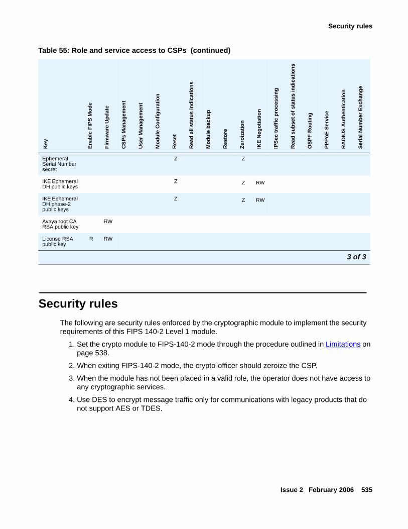
Security rules
Issue 2 February 2006 535
Security rulesThe following are security rules enforced by the cryptographic module to implement the security requirements of this FIPS 140-2 Level 1 module.
1. Set the crypto module to FIPS-140-2 mode through the procedure outlined in Limitations on page 538.
2. When exiting FIPS-140-2 mode, the crypto-officer should zeroize the CSP.
3. When the module has not been placed in a valid role, the operator does not have access to any cryptographic services.
4. Use DES to encrypt message traffic only for communications with legacy products that do not support AES or TDES.
Ephemeral Serial Number secret
Z Z
IKE Ephemeral DH public keys
Z Z RW
IKE Ephemeral DH phase-2 public keys
Z Z RW
Avaya root CA RSA public key
RW
License RSA public key
R RW
Table 55: Role and service access to CSPs (continued)K
ey
Enab
le F
IPS
Mod
e
Firm
war
e U
pdat
e
CSP
s M
anag
emen
t
Use
r Man
agem
ent
Mod
ule
Con
figur
atio
n
Res
et
Rea
d al
l sta
tus
indi
catio
ns
Mod
ule
back
up
Res
tore
Zero
izat
ion
IKE
Neg
otia
tion
IPSe
c tr
affic
pro
cess
ing
Rea
d su
bset
of s
tatu
s in
dica
tions
OSP
F R
outin
g
PPPo
E Se
rvic
e
RA
DIU
S A
uthe
ntic
atio
n
Seria
l Num
ber E
xcha
nge
3 of 3
FIPS
536 Administration for the Avaya G250 and Avaya G350 Media Gateways
5. The cryptographic module performs the following tests:
● Power up Self-Tests:
Cryptographic algorithm tests:● TDES Known Answer Test (tests DES performance as well)
● AES Known Answer Test
● SHA-1 Known Answer Test
● HMAC-SHA-1 Known Answer Test
● DRNG Known Answer Test
● RSA Known Answer Test
Gateway Software Integrity Test (32 bit CRC verification) and Booter Integrity Test (32 bit CRC verification)
Critical Functions Tests:● NVRAM Integrity test
● EEPROM Integrity Test
● Conditional Self-Tests:
● Continuous Random Number Generator (RNG) test - performed on all RNGs involved in crypto activities in FIPS-approved mode. Performed for PRNG x9.31 and Random Seed Generator.
● Bypass Test
● Firmware load test
6. Users can instruct the module to perform the power-up self-tests via power cycle.
7. Prior to each use, the internal RNG is tested using the conditional test specified in FIPS 140-2 §4.9.2.
8. Data output is inhibited during key generation, self-tests, zeroization, and error states.
9. The module supports concurrent operators and maintains separation of roles and services.
10. Users can plug-in and use any Avaya Media Module that does not support cryptographic functionality without restriction.
11. Media modules with cryptographic functionality are considered separate cryptographic modules that are not included within the cryptographic boundary of a gateway.
Password guidelines
Issue 2 February 2006 537
Password guidelinesBelow are general guidelines for defining passwords. To maximize security, it is recommended to follow these guidelines or use company guidelines where available.
● Password length
● User password: at least eight characters
● Other passwords: at least six characters
● PSK (pre-shared keys) for IKE: at least 13 characters
● Use a combination of upper and lower case letters, numbers and symbols.
Note:Note: You may use any printable character, such as ?, ! or *
● Do not use passwords that are easy to guess, such as names, dates, or telephone numbers.
● Keep passwords in a safe place.
Managing the module in FIPS-compliant modeIn FIPS-approved operation mode, all remote configuration activities (Telnet/TFTP/SNMP/FTP) are channeled through a VPN tunnel. The console port is used for local administration. Remote management through all other interfaces is disabled. In addition, the module will:
● Disable administration over SSH protocol.
● Disable dial-in and dial-out via the modem ports (serial and USB).
● Restrict troubleshooting services in the production environment by blocking all non-FIPS compliant dev/tech commands.
● Disable loading and output of configuration files from/to the SCP server.
● File transfers using TFTP and FTP are restricted to a VPN-encrypted tunnel.
! SECURITY ALERT:SECURITY ALERT: The “FIPS mode” of operation is permanent. If you do not fulfill all of the steps,
you void Gateway FIPS-compliant operation. The same happens if, after entering FIPS mode, you execute an operation that is not consistent with the FIPS-approved mode of operation. Also note that execution of the NVRAM Init or zeroize commands clear the above defined FIPS-approved mode configuration and returns the box to factory defaults.
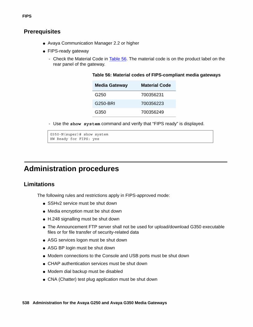
FIPS
538 Administration for the Avaya G250 and Avaya G350 Media Gateways
Prerequisites
● Avaya Communication Manager 2.2 or higher
● FIPS-ready gateway
- Check the Material Code in Table 56. The material code is on the product label on the rear panel of the gateway.
- Use the show system command and verify that “FIPS ready” is displayed.
Administration procedures
Limitations
The following rules and restrictions apply in FIPS-approved mode:
● SSHv2 service must be shut down
● Media encryption must be shut down
● H.248 signalling must be shut down
● The Announcement FTP server shall not be used for upload/download G350 executable files or for file transfer of security-related data
● ASG services logon must be shut down
● ASG BP login must be shut down
● Modem connections to the Console and USB ports must be shut down
● CHAP authentication services must be shut down
● Modem dial backup must be disabled
● CNA (Chatter) test plug application must be shut down
Table 56: Material codes of FIPS-compliant media gateways
Media Gateway Material Code
G250 700356231
G250-BRI 700356223
G350 700356249
G350-N(super)# show systemHW Ready for FIPS: yes
Administration procedures
Issue 2 February 2006 539
● SLS must be shut down
● Telnet service must be confined to IPSEC encrypted tunnel
● SNMP must be confined to SNMPv3 authentication service over an IPSEC encrypted tunnel
● TFTP configuration upload/download service must be confined to IPSEC encrypted tunnel
● FTP configuration upload/download service must be confined to IPSEC encrypted tunnel
● SCP client service must not be used
● Usage of Diffie-Hellman Group 1 for IKE key negotiation must be suppressed
● Usage of MD5 for IKE must be suppressed
● Usage of MD5 for ESP authentication operation in IPSEC must be suppressed
● Configuration channel between ICC/LSP (S8300) and Gateway (MGP) must be suppressed
FIPS-related CLI commands
The FIPS-related CLI commands include:
● zeroize
● enhanced security
● show self-test-status
For a full description see Avaya G250 and Avaya G350 CLI Reference, 03-300437
Entering FIPS mode
Prerequisites● User type – crypto officer
● FIPS-approved hardware. Version 3.0.x or higher.
● FIPS-approved Media Gateway firmware. Refer to the “Validation Lists for cryptographic Standards” on the NIST Web site: http://crc.nist.gov/cryptval/aes/aesval.html
● Valid VPN license
To enter FIPS mode:
1. Log in to the device through the local console port.
- User name: root
- Password: root
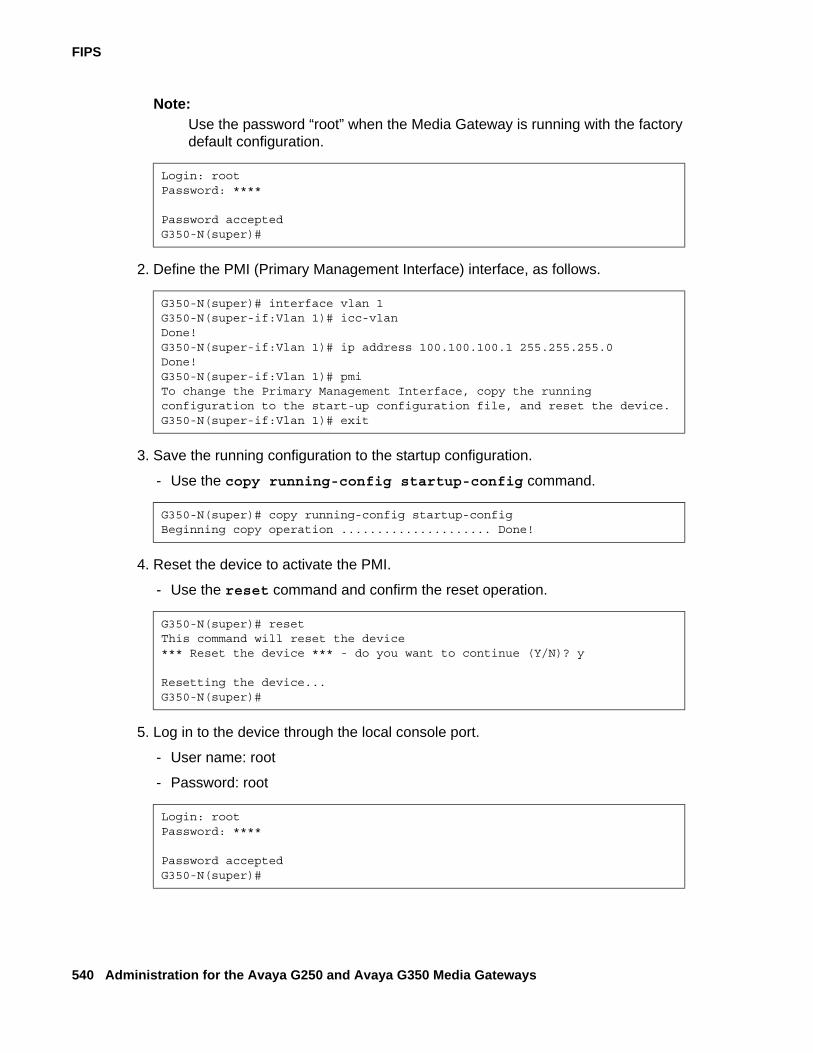
FIPS
540 Administration for the Avaya G250 and Avaya G350 Media Gateways
Note:Note: Use the password “root” when the Media Gateway is running with the factory
default configuration.
2. Define the PMI (Primary Management Interface) interface, as follows.
3. Save the running configuration to the startup configuration.
- Use the copy running-config startup-config command.
4. Reset the device to activate the PMI.
- Use the reset command and confirm the reset operation.
5. Log in to the device through the local console port.
- User name: root
- Password: root
Login: rootPassword: ****
Password acceptedG350-N(super)#
G350-N(super)# interface vlan 1G350-N(super-if:Vlan 1)# icc-vlanDone!G350-N(super-if:Vlan 1)# ip address 100.100.100.1 255.255.255.0Done!G350-N(super-if:Vlan 1)# pmiTo change the Primary Management Interface, copy the runningconfiguration to the start-up configuration file, and reset the device.G350-N(super-if:Vlan 1)# exit
G350-N(super)# copy running-config startup-configBeginning copy operation ..................... Done!
G350-N(super)# resetThis command will reset the device*** Reset the device *** - do you want to continue (Y/N)? y
Resetting the device...G350-N(super)#
Login: rootPassword: ****
Password acceptedG350-N(super)#
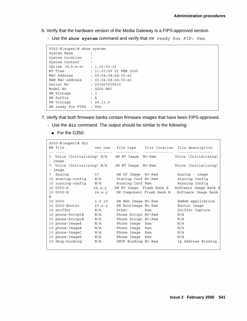
Administration procedures
Issue 2 February 2006 541
6. Verify that the hardware version of the Media Gateway is a FIPS-approved version.
- Use the show system command and verify that HW ready for FIP: Yes.
7. Verify that both firmware banks contain firmware images that have been FIPS-approved.
- Use the dir command. The output should be similar to the following:
● For the G350:
G350-N(super)# show systemSystem Name :System Location :System Contact :Uptime (d,h:m:s) : 1,16:03:33MV Time : 11:03:59 22 FEB 2005MAC Address : 00:04:0d:6d:30:e1WAN MAC address : 00:04:0d:6d:30:e1Serial No : 03IS07639510Model No : G250-BRIHW Vintage : 3HW Suffix : AFW Vintage : 24.11.0HW ready for FIPS : Yes
G350-N(super)# dirM# file ver num file type file location file description-- ---- -------- ---------- ------------- ----------------1 Voice (Initializing) N/A SW RT Image Nv-Ram Voice (Initializing) - image7 Voice (Initializing) N/A SW RT Image Nv-Ram Voice (Initializing) - image7 Analog 57 SW RT Image Nv-Ram Analog - image10 startup-config N/A Startup Conf Nv-Ram Startup Config10 running-config N/A Running Conf Ram Running Config10 G350-A 24.x.y SW RT Image Flash Bank A Software Image Bank A10 G350-B 24.x.y SW Component Flash Bank B Software Image Bank B10 G350 1.0.19 SW Web Image Nv-Ram EmWeb application10 G350-Booter 23.x.y SW BootImage Nv-Ram Booter Image10 sniffer N/A Other Ram Sniffer Capture10 phone-ScriptA N/A Phone Script Nv-Ram N/A10 phone-ScriptB N/A Phone Script Nv-Ram N/A10 phone-ImageA N/A Phone Image Ram N/A10 phone-ImageB N/A Phone Image Ram N/A10 phone-ImageC N/A Phone Image Ram N/A10 phone-ImageD N/A Phone Image Ram N/A10 dhcp-binding N/A DHCP Binding Nv-Ram Ip Address Binding
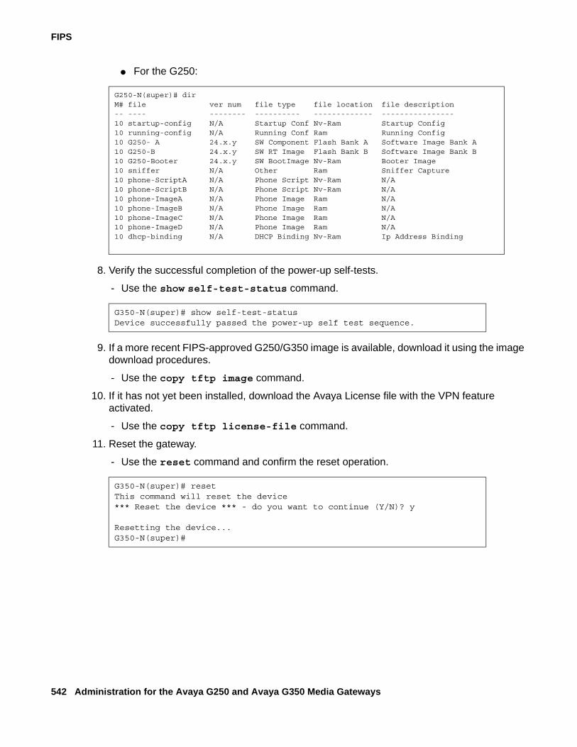
FIPS
542 Administration for the Avaya G250 and Avaya G350 Media Gateways
● For the G250:
8. Verify the successful completion of the power-up self-tests.
- Use the show self-test-status command.
9. If a more recent FIPS-approved G250/G350 image is available, download it using the image download procedures.
- Use the copy tftp image command.
10. If it has not yet been installed, download the Avaya License file with the VPN feature activated.
- Use the copy tftp license-file command.
11. Reset the gateway.
- Use the reset command and confirm the reset operation.
G250-N(super)# dirM# file ver num file type file location file description-- ---- -------- ---------- ------------- ----------------10 startup-config N/A Startup Conf Nv-Ram Startup Config10 running-config N/A Running Conf Ram Running Config10 G250- A 24.x.y SW Component Flash Bank A Software Image Bank A10 G250-B 24.x.y SW RT Image Flash Bank B Software Image Bank B10 G250-Booter 24.x.y SW BootImage Nv-Ram Booter Image10 sniffer N/A Other Ram Sniffer Capture10 phone-ScriptA N/A Phone Script Nv-Ram N/A10 phone-ScriptB N/A Phone Script Nv-Ram N/A10 phone-ImageA N/A Phone Image Ram N/A10 phone-ImageB N/A Phone Image Ram N/A10 phone-ImageC N/A Phone Image Ram N/A10 phone-ImageD N/A Phone Image Ram N/A10 dhcp-binding N/A DHCP Binding Nv-Ram Ip Address Binding
G350-N(super)# show self-test-statusDevice successfully passed the power-up self test sequence.
G350-N(super)# resetThis command will reset the device*** Reset the device *** - do you want to continue (Y/N)? y
Resetting the device...G350-N(super)#
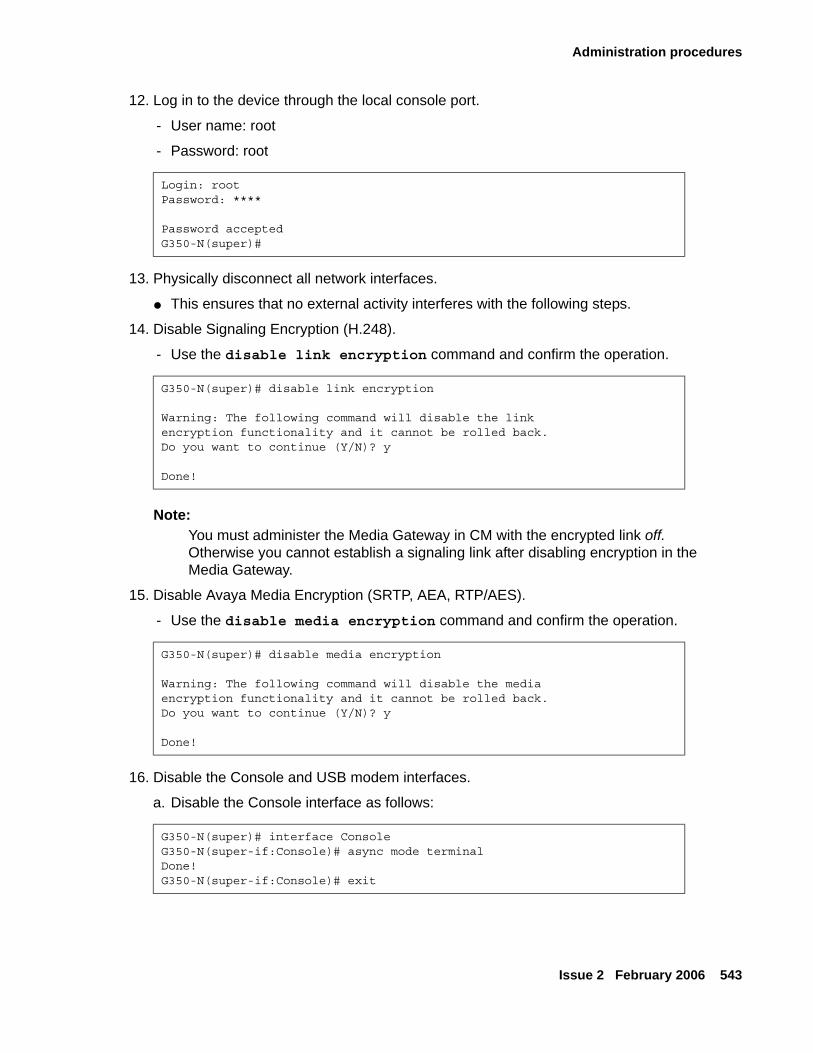
Administration procedures
Issue 2 February 2006 543
12. Log in to the device through the local console port.
- User name: root
- Password: root
13. Physically disconnect all network interfaces.
● This ensures that no external activity interferes with the following steps.
14. Disable Signaling Encryption (H.248).
- Use the disable link encryption command and confirm the operation.
Note:Note: You must administer the Media Gateway in CM with the encrypted link off.
Otherwise you cannot establish a signaling link after disabling encryption in the Media Gateway.
15. Disable Avaya Media Encryption (SRTP, AEA, RTP/AES).
- Use the disable media encryption command and confirm the operation.
16. Disable the Console and USB modem interfaces.
a. Disable the Console interface as follows:
Login: rootPassword: ****
Password acceptedG350-N(super)#
G350-N(super)# disable link encryption
Warning: The following command will disable the linkencryption functionality and it cannot be rolled back.Do you want to continue (Y/N)? y
Done!
G350-N(super)# disable media encryption
Warning: The following command will disable the mediaencryption functionality and it cannot be rolled back.Do you want to continue (Y/N)? y
Done!
G350-N(super)# interface ConsoleG350-N(super-if:Console)# async mode terminalDone!G350-N(super-if:Console)# exit
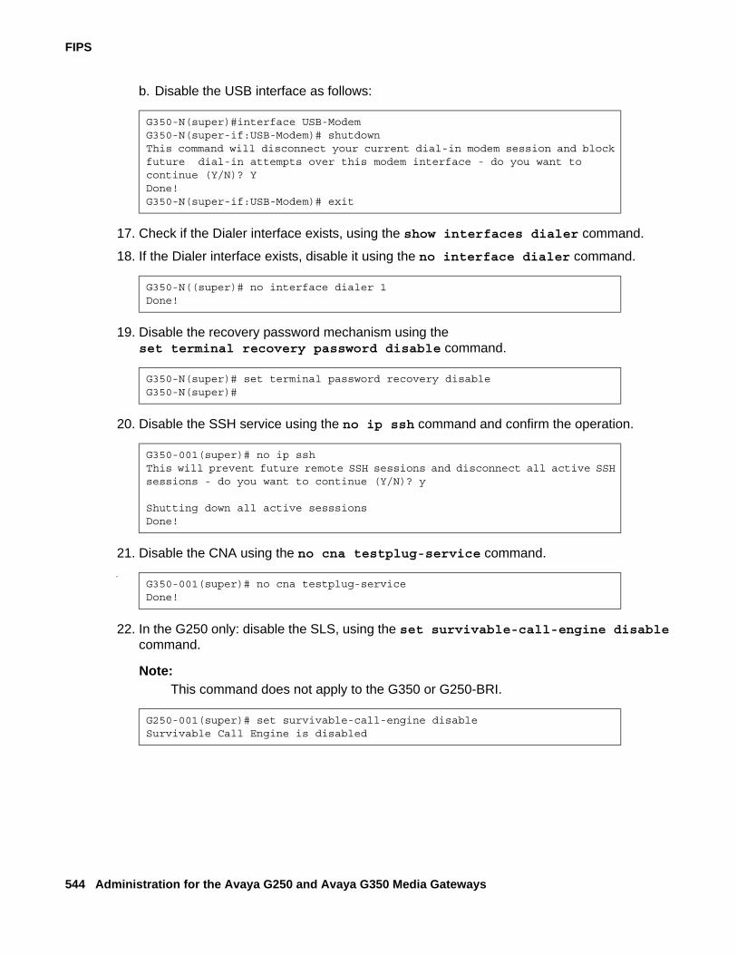
FIPS
544 Administration for the Avaya G250 and Avaya G350 Media Gateways
b. Disable the USB interface as follows:
17. Check if the Dialer interface exists, using the show interfaces dialer command.
18. If the Dialer interface exists, disable it using the no interface dialer command.
19. Disable the recovery password mechanism using the set terminal recovery password disable command.
20. Disable the SSH service using the no ip ssh command and confirm the operation.
21. Disable the CNA using the no cna testplug-service command..
22. In the G250 only: disable the SLS, using the set survivable-call-engine disable command.
Note:Note: This command does not apply to the G350 or G250-BRI.
G350-N(super)#interface USB-ModemG350-N(super-if:USB-Modem)# shutdownThis command will disconnect your current dial-in modem session and block future dial-in attempts over this modem interface - do you want to continue (Y/N)? YDone!G350-N(super-if:USB-Modem)# exit
G350-N((super)# no interface dialer 1Done!
G350-N(super)# set terminal password recovery disableG350-N(super)#
G350-001(super)# no ip sshThis will prevent future remote SSH sessions and disconnect all active SSH sessions - do you want to continue (Y/N)? y
Shutting down all active sesssionsDone!
G350-001(super)# no cna testplug-serviceDone!
G250-001(super)# set survivable-call-engine disableSurvivable Call Engine is disabled
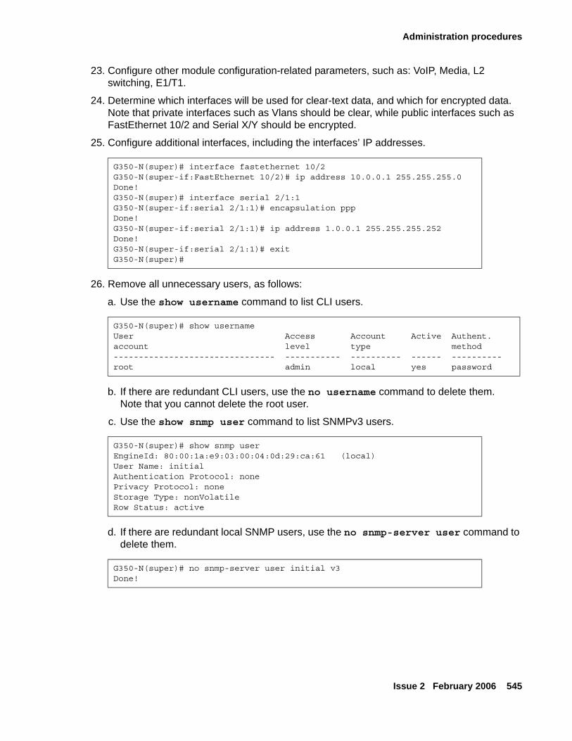
Administration procedures
Issue 2 February 2006 545
23. Configure other module configuration-related parameters, such as: VoIP, Media, L2 switching, E1/T1.
24. Determine which interfaces will be used for clear-text data, and which for encrypted data. Note that private interfaces such as Vlans should be clear, while public interfaces such as FastEthernet 10/2 and Serial X/Y should be encrypted.
25. Configure additional interfaces, including the interfaces’ IP addresses.
26. Remove all unnecessary users, as follows:
a. Use the show username command to list CLI users.
b. If there are redundant CLI users, use the no username command to delete them. Note that you cannot delete the root user.
c. Use the show snmp user command to list SNMPv3 users.
d. If there are redundant local SNMP users, use the no snmp-server user command to delete them.
G350-N(super)# interface fastethernet 10/2G350-N(super-if:FastEthernet 10/2)# ip address 10.0.0.1 255.255.255.0Done!G350-N(super)# interface serial 2/1:1G350-N(super-if:serial 2/1:1)# encapsulation pppDone!G350-N(super-if:serial 2/1:1)# ip address 1.0.0.1 255.255.255.252Done!G350-N(super-if:serial 2/1:1)# exitG350-N(super)#
G350-N(super)# show usernameUser Access Account Active Authent.account level type method-------------------------------- ----------- ---------- ------ ----------root admin local yes password
G350-N(super)# show snmp userEngineId: 80:00:1a:e9:03:00:04:0d:29:ca:61 (local)User Name: initialAuthentication Protocol: nonePrivacy Protocol: noneStorage Type: nonVolatileRow Status: active
G350-N(super)# no snmp-server user initial v3Done!
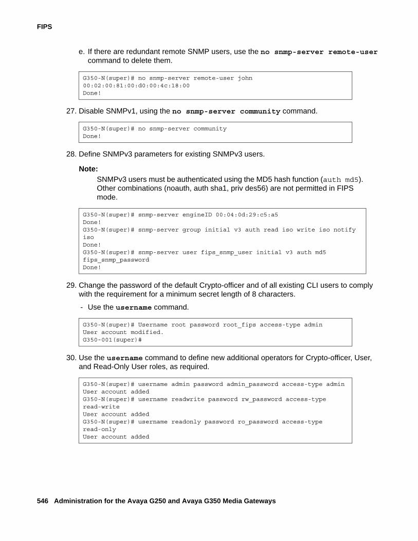
FIPS
546 Administration for the Avaya G250 and Avaya G350 Media Gateways
e. If there are redundant remote SNMP users, use the no snmp-server remote-user command to delete them.
27. Disable SNMPv1, using the no snmp-server community command.
28. Define SNMPv3 parameters for existing SNMPv3 users.
Note:Note: SNMPv3 users must be authenticated using the MD5 hash function (auth md5).
Other combinations (noauth, auth sha1, priv des56) are not permitted in FIPS mode.
29. Change the password of the default Crypto-officer and of all existing CLI users to comply with the requirement for a minimum secret length of 8 characters.
- Use the username command.
30. Use the username command to define new additional operators for Crypto-officer, User, and Read-Only User roles, as required.
G350-N(super)# no snmp-server remote-user john 00:02:00:81:00:d0:00:4c:18:00Done!
G350-N(super)# no snmp-server communityDone!
G350-N(super)# snmp-server engineID 00:04:0d:29:c5:a5Done!G350-N(super)# snmp-server group initial v3 auth read iso write iso notify isoDone!G350-N(super)# snmp-server user fips_snmp_user initial v3 auth md5 fips_snmp_passwordDone!
G350-N(super)# Username root password root_fips access-type adminUser account modified.G350-001(super)#
G350-N(super)# username admin password admin_password access-type adminUser account addedG350-N(super)# username readwrite password rw_password access-type read-writeUser account addedG350-N(super)# username readonly password ro_password access-type read-onlyUser account added
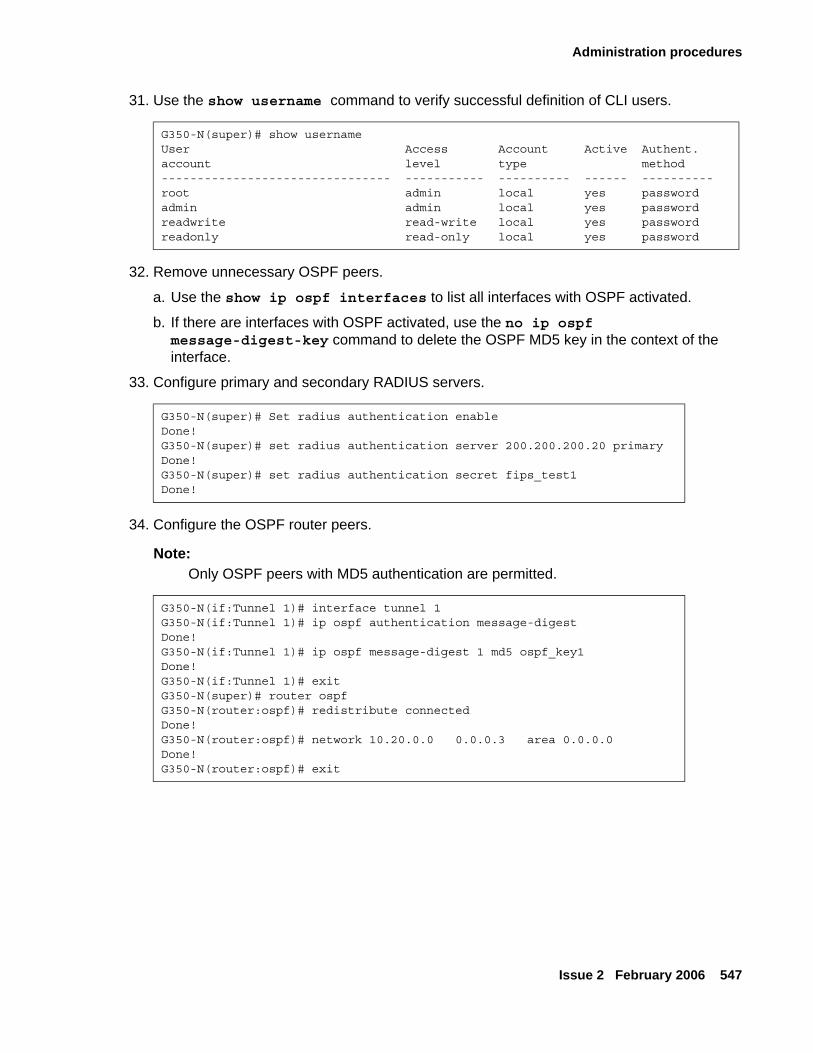
Administration procedures
Issue 2 February 2006 547
31. Use the show username command to verify successful definition of CLI users.
32. Remove unnecessary OSPF peers.
a. Use the show ip ospf interfaces to list all interfaces with OSPF activated.
b. If there are interfaces with OSPF activated, use the no ip ospf message-digest-key command to delete the OSPF MD5 key in the context of the interface.
33. Configure primary and secondary RADIUS servers.
34. Configure the OSPF router peers.
Note:Note: Only OSPF peers with MD5 authentication are permitted.
G350-N(super)# show usernameUser Access Account Active Authent.account level type method-------------------------------- ----------- ---------- ------ ----------root admin local yes passwordadmin admin local yes passwordreadwrite read-write local yes passwordreadonly read-only local yes password
G350-N(super)# Set radius authentication enableDone!G350-N(super)# set radius authentication server 200.200.200.20 primaryDone!G350-N(super)# set radius authentication secret fips_test1Done!
G350-N(if:Tunnel 1)# interface tunnel 1G350-N(if:Tunnel 1)# ip ospf authentication message-digestDone!G350-N(if:Tunnel 1)# ip ospf message-digest 1 md5 ospf_key1Done!G350-N(if:Tunnel 1)# exitG350-N(super)# router ospfG350-N(router:ospf)# redistribute connectedDone!G350-N(router:ospf)# network 10.20.0.0 0.0.0.3 area 0.0.0.0Done!G350-N(router:ospf)# exit
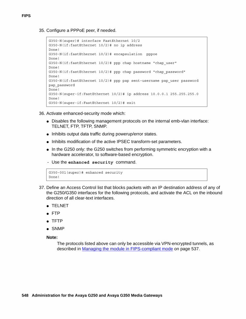
FIPS
548 Administration for the Avaya G250 and Avaya G350 Media Gateways
35. Configure a PPPoE peer, if needed.
36. Activate enhanced-security mode which:
● Disables the following management protocols on the internal emb-vlan interface: TELNET, FTP, TFTP, SNMP.
● Inhibits output data traffic during powerup/error states.
● Inhibits modification of the active IPSEC transform-set parameters.
● In the G250 only: the G250 switches from performing symmetric encryption with a hardware accelerator, to software-based encryption.
- Use the enhanced security command.
37. Define an Access Control list that blocks packets with an IP destination address of any of the G250/G350 interfaces for the following protocols, and activate the ACL on the inbound direction of all clear-text interfaces.
● TELNET
● FTP
● TFTP
● SNMP
Note:Note: The protocols listed above can only be accessible via VPN-encrypted tunnels, as
described in Managing the module in FIPS-compliant mode on page 537.
G350-N(super)# interface FastEthernet 10/2G350-N(if:fastEthernet 10/2)# no ip addressDone!G350-N(if:fastEthernet 10/2)# encapsulation pppoeDone!G350-N(if:fastEthernet 10/2)# ppp chap hostname "chap_user"Done!G350-N(if:fastEthernet 10/2)# ppp chap password "chap_password"Done!G350-N(if:fastEthernet 10/2)# ppp pap sent-username pap_user password pap_passwordDone!G350-N(super-if:FastEthernet 10/2)# ip address 10.0.0.1 255.255.255.0Done!G350-N(super-if:FastEthernet 10/2)# exit
G350-001(super)# enhanced securityDone!
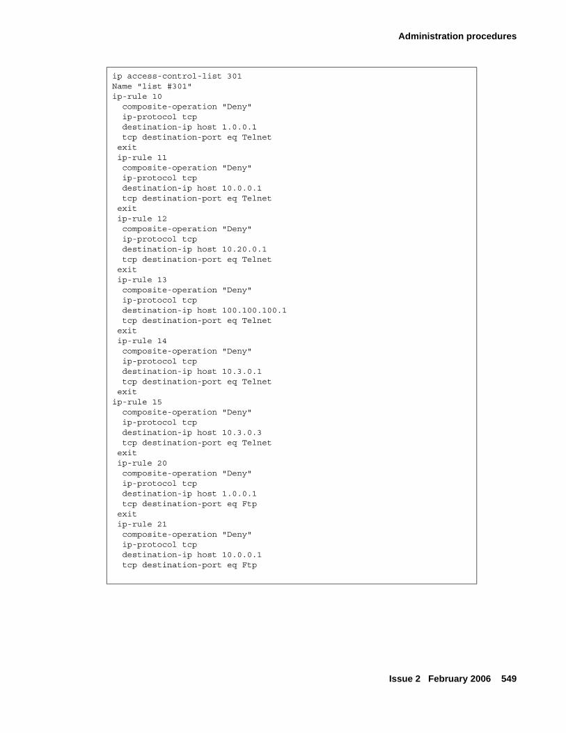
Administration procedures
Issue 2 February 2006 549
ip access-control-list 301Name "list #301"ip-rule 10 composite-operation "Deny" ip-protocol tcp destination-ip host 1.0.0.1
tcp destination-port eq Telnet exit ip-rule 11 composite-operation "Deny" ip-protocol tcp destination-ip host 10.0.0.1 tcp destination-port eq Telnet exit ip-rule 12 composite-operation "Deny" ip-protocol tcp destination-ip host 10.20.0.1 tcp destination-port eq Telnet exit ip-rule 13 composite-operation "Deny" ip-protocol tcp destination-ip host 100.100.100.1 tcp destination-port eq Telnet exit ip-rule 14 composite-operation "Deny" ip-protocol tcp destination-ip host 10.3.0.1
tcp destination-port eq Telnet exitip-rule 15 composite-operation "Deny" ip-protocol tcp destination-ip host 10.3.0.3 tcp destination-port eq Telnet exit ip-rule 20 composite-operation "Deny" ip-protocol tcp destination-ip host 1.0.0.1
tcp destination-port eq Ftp exit ip-rule 21 composite-operation "Deny" ip-protocol tcp destination-ip host 10.0.0.1
tcp destination-port eq Ftp
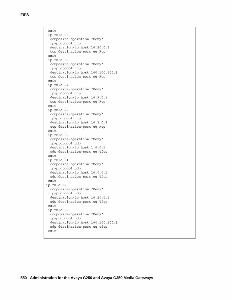
FIPS
550 Administration for the Avaya G250 and Avaya G350 Media Gateways
exit ip-rule 22 composite-operation "Deny" ip-protocol tcp destination-ip host 10.20.0.1
tcp destination-port eq Ftp exit ip-rule 23 composite-operation "Deny" ip-protocol tcp destination-ip host 100.100.100.1
tcp destination-port eq Ftp exit ip-rule 24 composite-operation "Deny" ip-protocol tcp destination-ip host 10.3.0.1
tcp destination-port eq Ftp exit ip-rule 25 composite-operation "Deny" ip-protocol tcp destination-ip host 10.3.0.3
tcp destination-port eq Ftp exit ip-rule 30 composite-operation "Deny" ip-protocol udp destination-ip host 1.0.0.1 udp destination-port eq Tftp exit ip-rule 31 composite-operation "Deny" ip-protocol udp destination-ip host 10.0.0.1 udp destination-port eq Tftp exitip-rule 32 composite-operation "Deny" ip-protocol udp destination-ip host 10.20.0.1 udp destination-port eq Tftp exit ip-rule 33 composite-operation "Deny" ip-protocol udp destination-ip host 100.100.100.1 udp destination-port eq Tftp exit

Administration procedures
Issue 2 February 2006 551
ip-rule 34 composite-operation "Deny" ip-protocol udp destination-ip host 10.3.0.1 udp destination-port eq Tftp exit ip-rule 35 composite-operation "Deny" ip-protocol udp destination-ip host 10.3.0.3 udp destination-port eq Tftp exit ip-rule 40 composite-operation "Deny" ip-protocol udp destination-ip host 1.0.0.1 udp destination-port eq Snmp exit ip-rule 41 composite-operation "Deny" ip-protocol udp destination-ip host 10.0.0.1 udp destination-port eq Snmp exit ip-rule 42 composite-operation "Deny" ip-protocol udp destination-ip host 10.20.0.1 udp destination-port eq Snmp exit ip-rule 43 composite-operation "Deny" ip-protocol udp destination-ip host 100.100.100.1 udp destination-port eq Snmp exitip-rule 44 composite-operation "Deny" ip-protocol udp destination-ip host 10.3.0.1 udp destination-port eq Snmp exit ip-rule 45 composite-operation "Deny" ip-protocol udp destination-ip host 10.3.0.3 udp destination-port eq Snmp exit
exitinterface vlan 1 ip access-group 301 inexit
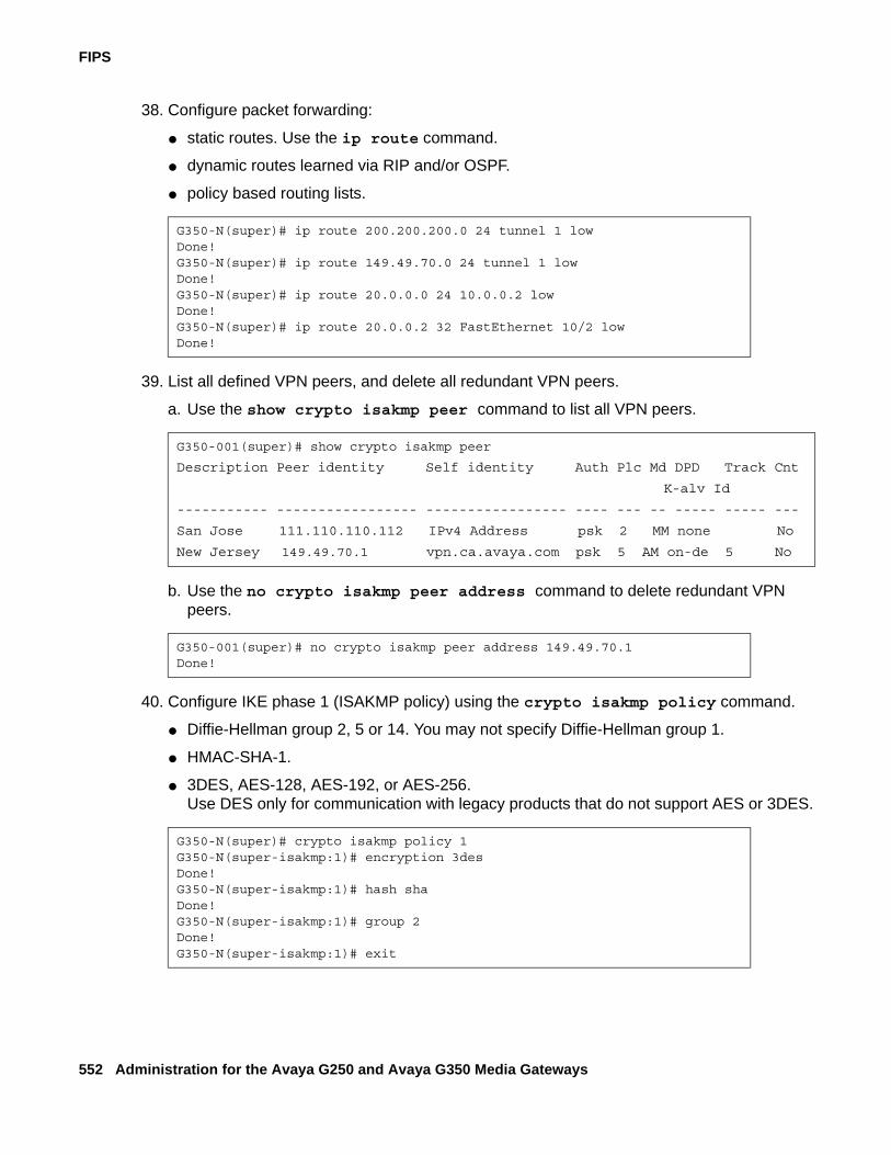
FIPS
552 Administration for the Avaya G250 and Avaya G350 Media Gateways
38. Configure packet forwarding:
● static routes. Use the ip route command.
● dynamic routes learned via RIP and/or OSPF.
● policy based routing lists.
39. List all defined VPN peers, and delete all redundant VPN peers.
a. Use the show crypto isakmp peer command to list all VPN peers.
b. Use the no crypto isakmp peer address command to delete redundant VPN peers.
40. Configure IKE phase 1 (ISAKMP policy) using the crypto isakmp policy command.
● Diffie-Hellman group 2, 5 or 14. You may not specify Diffie-Hellman group 1.
● HMAC-SHA-1.
● 3DES, AES-128, AES-192, or AES-256. Use DES only for communication with legacy products that do not support AES or 3DES.
G350-N(super)# ip route 200.200.200.0 24 tunnel 1 lowDone!G350-N(super)# ip route 149.49.70.0 24 tunnel 1 lowDone!G350-N(super)# ip route 20.0.0.0 24 10.0.0.2 lowDone!G350-N(super)# ip route 20.0.0.2 32 FastEthernet 10/2 lowDone!
G350-001(super)# show crypto isakmp peer
Description Peer identity Self identity Auth Plc Md DPD Track Cnt
K-alv Id
----------- ----------------- ----------------- ---- --- -- ----- ----- ---
San Jose 111.110.110.112 IPv4 Address psk 2 MM none No
New Jersey 149.49.70.1 vpn.ca.avaya.com psk 5 AM on-de 5 No
G350-001(super)# no crypto isakmp peer address 149.49.70.1Done!
G350-N(super)# crypto isakmp policy 1G350-N(super-isakmp:1)# encryption 3desDone!G350-N(super-isakmp:1)# hash shaDone!G350-N(super-isakmp:1)# group 2Done!G350-N(super-isakmp:1)# exit
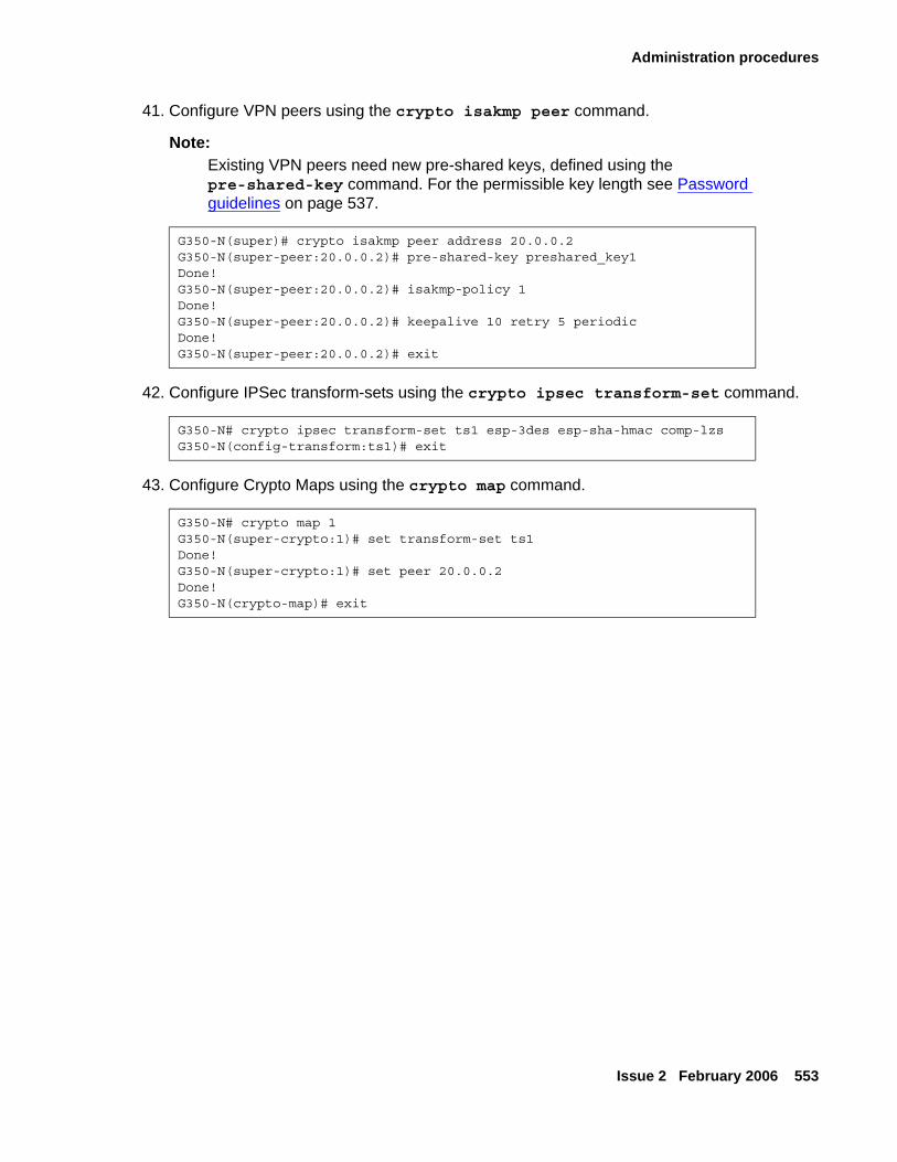
Administration procedures
Issue 2 February 2006 553
41. Configure VPN peers using the crypto isakmp peer command.
Note:Note: Existing VPN peers need new pre-shared keys, defined using the
pre-shared-key command. For the permissible key length see Password guidelines on page 537.
42. Configure IPSec transform-sets using the crypto ipsec transform-set command.
43. Configure Crypto Maps using the crypto map command.
G350-N(super)# crypto isakmp peer address 20.0.0.2G350-N(super-peer:20.0.0.2)# pre-shared-key preshared_key1Done!G350-N(super-peer:20.0.0.2)# isakmp-policy 1Done!G350-N(super-peer:20.0.0.2)# keepalive 10 retry 5 periodicDone!G350-N(super-peer:20.0.0.2)# exit
G350-N# crypto ipsec transform-set ts1 esp-3des esp-sha-hmac comp-lzsG350-N(config-transform:ts1)# exit
G350-N# crypto map 1G350-N(super-crypto:1)# set transform-set ts1Done!G350-N(super-crypto:1)# set peer 20.0.0.2Done!G350-N(crypto-map)# exit
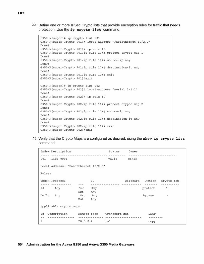
FIPS
554 Administration for the Avaya G250 and Avaya G350 Media Gateways
44. Define one or more IPSec Crypto lists that provide encryption rules for traffic that needs protection. Use the ip crypto-list command.
45. Verify that the Crypto Maps are configured as desired, using the show ip crypto-list command.
G350-N(super)# ip crypto-list 901G350-N(super-Crypto 901)# local-address “FastEthernet 10/2.0”Done!G350-N(super-Crypto 901)# ip-rule 10G350-N(super-Crypto 901/ip rule 10)# protect crypto map 1Done!G350-N(super-Crypto 901/ip rule 10)# source-ip anyDonw!G350-N(super-Crypto 901/ip rule 10)# destination-ip anyDone!G350-N(super-Crypto 901/ip rule 10)# exitG350-N(super-Crypto 901)#exit
G350-N(super)# ip crypto-list 902G350-N(super-Crypto 902)# local-address “serial 2/1:1”Done!G350-N(super-Crypto 902)# ip-rule 10Done!G350-N(super-Crypto 902/ip rule 10)# protect crypto map 2Done!G350-N(super-Crypto 902/ip rule 10)# source-ip anyDone!G350-N(super-Crypto 902/ip rule 10)# destination-ip anyDone!G350-N(super-Crypto 902/ip rule 10)# exitG350-N(super-Crypto 902)#exit
Index Description Status Owner----- ------------------------------- --------- --------------------------901 list #901 valid other
Local address: “FastEthernet 10/2.0”
Rules:
Index Protocol IP Wildcard Action Crypto map----- ----------- --- ---------------- ----------- ------- ----------10 Any Src Any protect 1
Dst AnyDeflt Any Src Any bypass -
Dst Any
Applicable crypto maps:
Id Description Remote peer Transform-set DSCP-- --------------- -------------- -------------------- --------1 20.0.0.2 ts1 copy
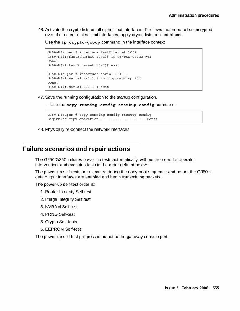
Administration procedures
Issue 2 February 2006 555
46. Activate the crypto-lists on all cipher-text interfaces. For flows that need to be encrypted even if directed to clear-text interfaces, apply crypto lists to all interfaces.
Use the ip crypto-group command in the interface context
47. Save the running configuration to the startup configuration.
- Use the copy running-config startup-config command.
48. Physically re-connect the network interfaces.
Failure scenarios and repair actionsThe G250/G350 initiates power up tests automatically, without the need for operator intervention, and executes tests in the order defined below.The power-up self-tests are executed during the early boot sequence and before the G350’s data output interfaces are enabled and begin transmitting packets.
The power-up self-test order is:
1. Booter Integrity Self test
2. Image Integrity Self test
3. NVRAM Self test
4. PRNG Self-test
5. Crypto Self-tests
6. EEPROM Self-test
The power-up self test progress is output to the gateway console port.
G350-N(super)# interface FastEthernet 10/2G350-N(if:fastEthernet 10/2)# ip crypto-group 901Done!G350-N(if:fastEthernet 10/2)# exit
G350-N(super)# interface serial 2/1:1G350-N(if:serial 2/1:1)# ip crypto-group 902Done!G350-N(if:serial 2/1:1)# exit
G350-N(super)# copy running-config startup-configBeginning copy operation ..................... Done!
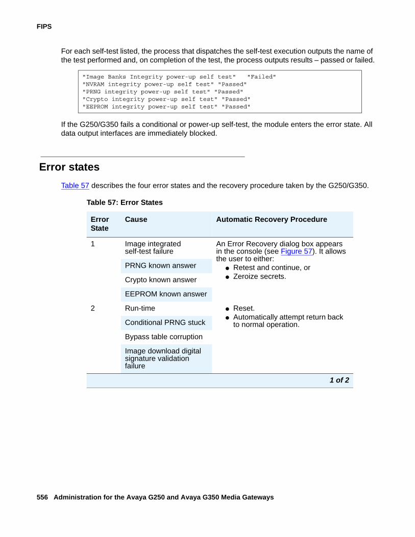
FIPS
556 Administration for the Avaya G250 and Avaya G350 Media Gateways
For each self-test listed, the process that dispatches the self-test execution outputs the name of the test performed and, on completion of the test, the process outputs results – passed or failed.
If the G250/G350 fails a conditional or power-up self-test, the module enters the error state. All data output interfaces are immediately blocked.
Error statesTable 57 describes the four error states and the recovery procedure taken by the G250/G350.
"Image Banks Integrity power-up self test" "Failed""NVRAM integrity power-up self test" "Passed""PRNG integrity power-up self test" "Passed""Crypto integrity power-up self test" "Passed""EEPROM integrity power-up self test" "Passed"
Table 57: Error States
Error State
Cause Automatic Recovery Procedure
1 Image integrated self-test failure
An Error Recovery dialog box appears in the console (see Figure 57). It allows the user to either:
● Retest and continue, or● Zeroize secrets.
PRNG known answer
Crypto known answer
EEPROM known answer
2 Run-time ● Reset.● Automatically attempt return back
to normal operation.Conditional PRNG stuck
Bypass table corruption
Image download digital signature validation failure
1 of 2
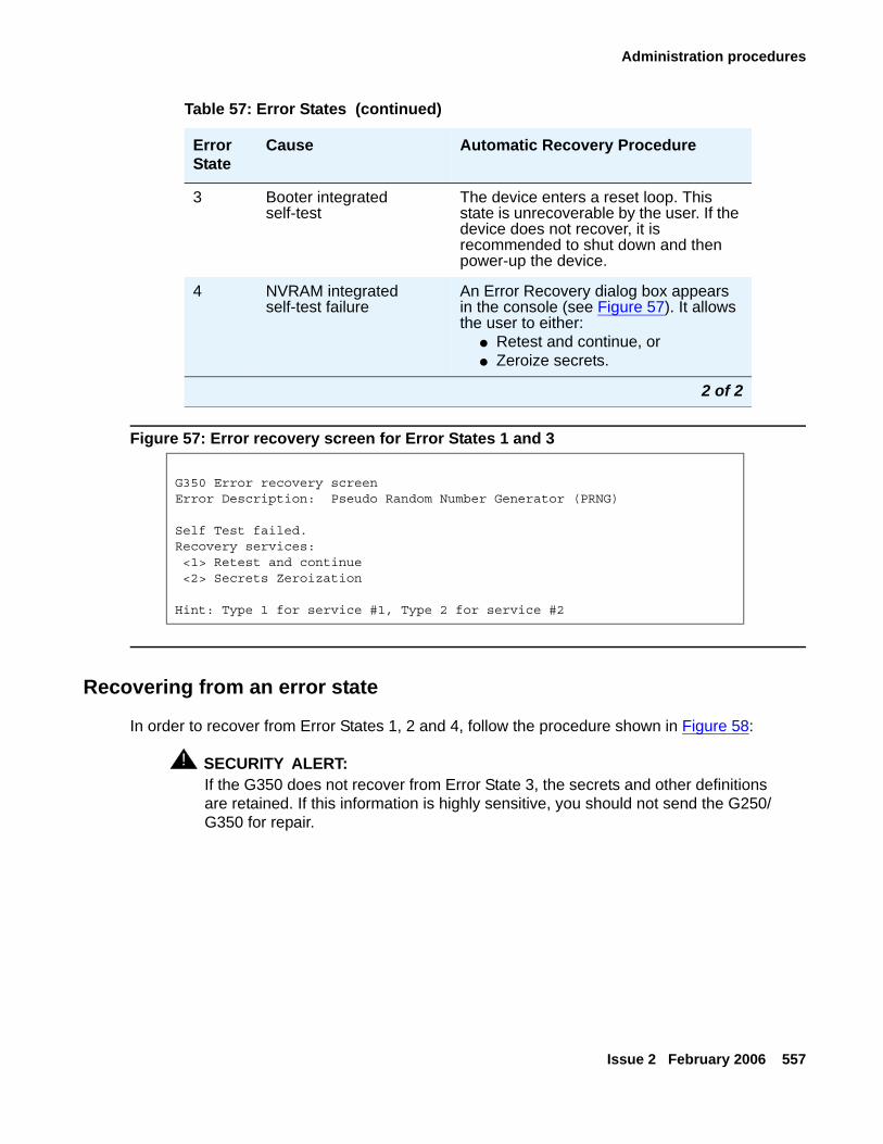
Administration procedures
Issue 2 February 2006 557
Figure 57: Error recovery screen for Error States 1 and 3
Recovering from an error state
In order to recover from Error States 1, 2 and 4, follow the procedure shown in Figure 58:
! SECURITY ALERT:SECURITY ALERT: If the G350 does not recover from Error State 3, the secrets and other definitions
are retained. If this information is highly sensitive, you should not send the G250/G350 for repair.
3 Booter integrated self-test
The device enters a reset loop. This state is unrecoverable by the user. If the device does not recover, it is recommended to shut down and then power-up the device.
4 NVRAM integrated self-test failure
An Error Recovery dialog box appears in the console (see Figure 57). It allows the user to either:
● Retest and continue, or● Zeroize secrets.
G350 Error recovery screenError Description: Pseudo Random Number Generator (PRNG)
Self Test failed.Recovery services: <1> Retest and continue <2> Secrets Zeroization
Hint: Type 1 for service #1, Type 2 for service #2
Table 57: Error States (continued)
Error State
Cause Automatic Recovery Procedure
2 of 2
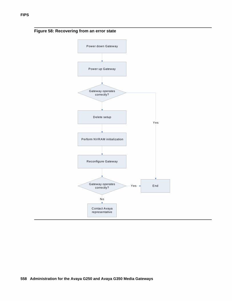
FIPS
558 Administration for the Avaya G250 and Avaya G350 Media Gateways
Figure 58: Recovering from an error state
Power down Gateway
Power up Gateway
Gateway operates correctly?
End
Yes
Delete setup
Perform NVRAM initialization
Reconfigure Gateway
Gateway operates correctly? Yes
Contact Avaya representative
No
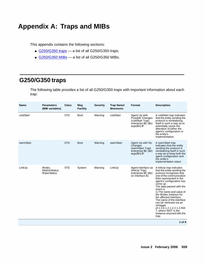
Issue 2 February 2006 559
Appendix A: Traps and MIBs
This appendix contains the following sections:
● G250/G350 traps — a list of all G250/G350 traps.
● G250/G350 MIBs — a list of all G250/G350 MIBs.
G250/G350 trapsThe following table provides a list of all G250/G350 traps with important information about each trap:
Name Parameters (MIB variables)
Class Msg Facility
Severity Trap Name/ Mnemonic
Format Description
coldStart STD Boot Warning coldStart Agent Up with Possible Changes (coldStart Trap) enterprise:$E ($e) args($#):$*
A coldStart trap indicates that the entity sending the protocol is reinitializing itself in such a way as to potentially cause the alteration of either the agent's configuration or the entity's implementation.
warmStart STD Boot Warning warmStart Agent Up with No Changes (warmStart Trap) enterprise:$E ($e) args($#):$*
A warmStart trap indicates that the entity sending the protocol is reinitializing itself in such a way as to keep both the agent configuration and the entity's implementation intact.
LinkUp ifIndex,ifAdminStatus,ifOperStatus
STD System Warning LinkUp Agent Interface Up (linkUp Trap) enterprise:$E ($e) on interface $1
A linkUp trap indicates that the entity sending the protocol recognizes that one of the communication links represented in the agent's configuration has come up.The data passed with the event is1) The name and value of the ifIndex instance for the affected interface. The name of the interface can be retrieved via an snmpget of.1.3.6.1.2.1.2.2.1.2.INST, where INST is the instance returned with the trap.
1 of 9
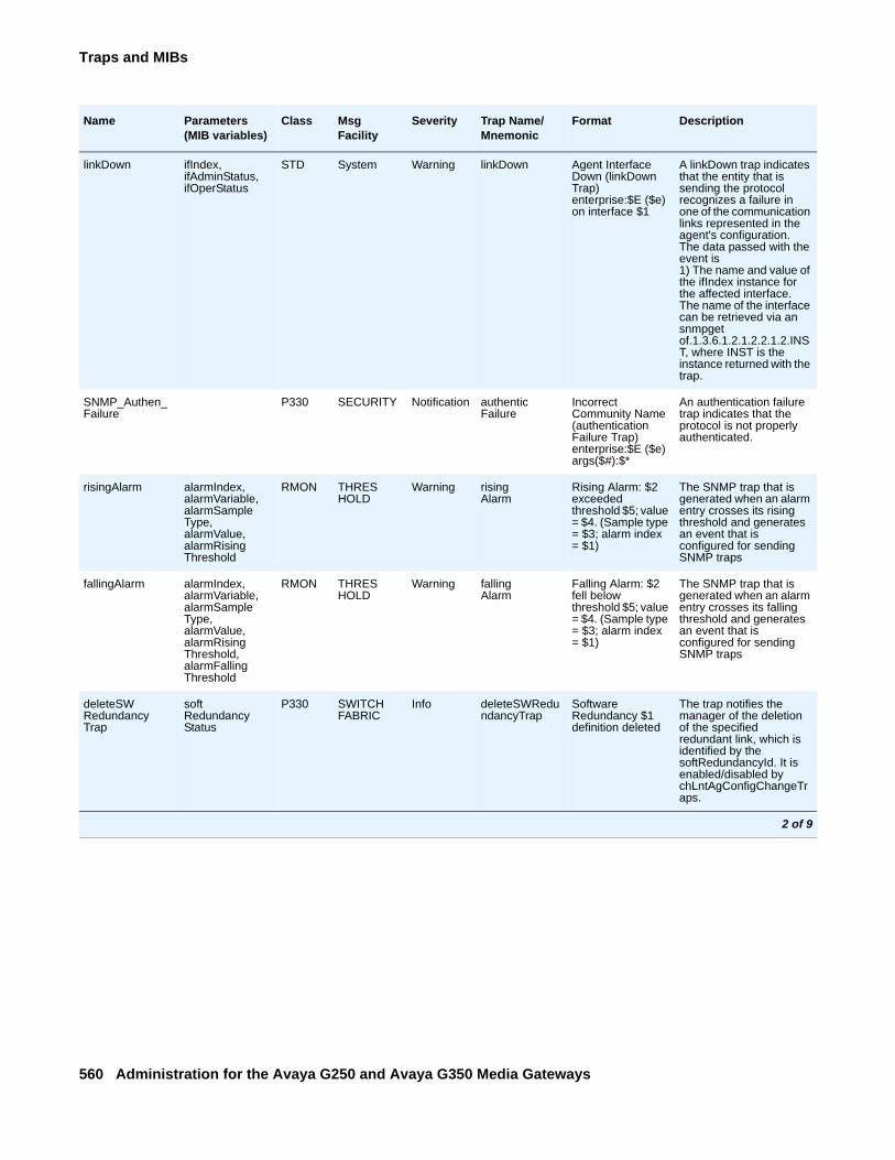
Traps and MIBs
560 Administration for the Avaya G250 and Avaya G350 Media Gateways
linkDown ifIndex,ifAdminStatus,ifOperStatus
STD System Warning linkDown Agent Interface Down (linkDown Trap) enterprise:$E ($e) on interface $1
A linkDown trap indicates that the entity that is sending the protocol recognizes a failure in one of the communication links represented in the agent's configuration.The data passed with the event is1) The name and value of the ifIndex instance for the affected interface. The name of the interface can be retrieved via an snmpget of.1.3.6.1.2.1.2.2.1.2.INST, where INST is the instance returned with the trap.
SNMP_Authen_Failure
P330 SECURITY Notification authenticFailure
Incorrect Community Name (authenticationFailure Trap) enterprise:$E ($e) args($#):$*
An authentication failure trap indicates that the protocol is not properly authenticated.
risingAlarm alarmIndex,alarmVariable,alarmSampleType,alarmValue,alarmRisingThreshold
RMON THRESHOLD
Warning risingAlarm
Rising Alarm: $2 exceeded threshold $5; value = $4. (Sample type = $3; alarm index = $1)
The SNMP trap that is generated when an alarm entry crosses its rising threshold and generates an event that is configured for sending SNMP traps
fallingAlarm alarmIndex,alarmVariable,alarmSampleType,alarmValue,alarmRisingThreshold, alarmFallingThreshold
RMON THRESHOLD
Warning fallingAlarm
Falling Alarm: $2 fell below threshold $5; value = $4. (Sample type = $3; alarm index = $1)
The SNMP trap that is generated when an alarm entry crosses its falling threshold and generates an event that is configured for sending SNMP traps
deleteSWRedundancyTrap
softRedundancyStatus
P330 SWITCHFABRIC
Info deleteSWRedundancyTrap
Software Redundancy $1 definition deleted
The trap notifies the manager of the deletion of the specified redundant link, which is identified by the softRedundancyId. It is enabled/disabled by chLntAgConfigChangeTraps.
Name Parameters (MIB variables)
Class Msg Facility
Severity Trap Name/ Mnemonic
Format Description
2 of 9
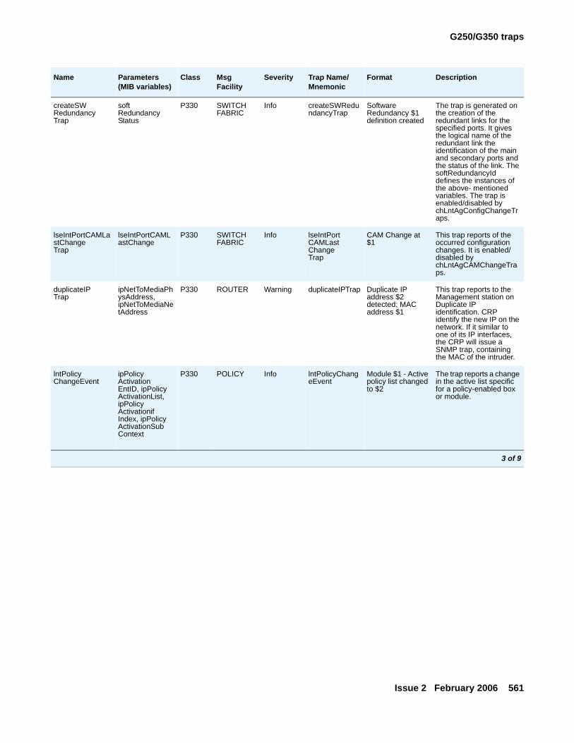
G250/G350 traps
Issue 2 February 2006 561
createSWRedundancyTrap
softRedundancyStatus
P330 SWITCHFABRIC
Info createSWRedundancyTrap
Software Redundancy $1 definition created
The trap is generated on the creation of the redundant links for the specified ports. It gives the logical name of the redundant link the identification of the main and secondary ports and the status of the link. The softRedundancyId defines the instances of the above- mentioned variables. The trap is enabled/disabled by chLntAgConfigChangeTraps.
lseIntPortCAMLastChangeTrap
lseIntPortCAMLastChange
P330 SWITCHFABRIC
Info lseIntPortCAMLastChangeTrap
CAM Change at $1
This trap reports of the occurred configuration changes. It is enabled/disabled by chLntAgCAMChangeTraps.
duplicateIPTrap
ipNetToMediaPhysAddress, ipNetToMediaNetAddress
P330 ROUTER Warning duplicateIPTrap Duplicate IP address $2 detected; MAC address $1
This trap reports to the Management station on Duplicate IP identification. CRP identify the new IP on the network. If it similar to one of its IP interfaces, the CRP will issue a SNMP trap, containing the MAC of the intruder.
lntPolicyChangeEvent
ipPolicyActivationEntID, ipPolicyActivationList, ipPolicyActivationifIndex, ipPolicyActivationSubContext
P330 POLICY Info lntPolicyChangeEvent
Module $1 - Active policy list changed to $2
The trap reports a change in the active list specific for a policy-enabled box or module.
Name Parameters (MIB variables)
Class Msg Facility
Severity Trap Name/ Mnemonic
Format Description
3 of 9
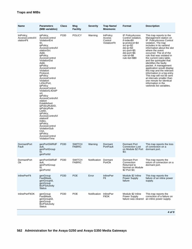
Traps and MIBs
562 Administration for the Avaya G250 and Avaya G350 Media Gateways
lntPolicyAccessControlViolationFlt
ipPolicyAccessControlViolationEntID, ipPolicyAccessControlViolationSrcAddr, ipPolicyAccessControlViolationDstAddr, ipPolicyAccessControlViolationProtocol, ipPolicyAccessControlViolationL4SrcPort, ipPolicyAccessControlViolationL4DstPort, ipPolicyAccessControlViolationEstablished, ipPolicyRuleID, ipPolicyRuleListID, ipPolicyAccessControlViolationIfIndex, ipPolicyAccessControlViolationSubCtxt, ipPolicyAccessControlViolationTime
P330 POLICY Warning lntPolicyAccessControlViolationFlt
IP PolicyAccess Control violation, if-index$9 ip-protocol=$4 src-ip=$2 dst-ip=$3 src-port=$5 dst-port=$6 rule-id=$8 rule-list=$$9
This trap reports to the Management station on IP PolicyAccess Control violation. The trap includes in its varbind information about the slot where the event occurred. The id of the rule that was violated in the current rules table, and the quintuplet that identifies the faulty packet. A management application would display this trap and the relevant information in a log entry. This trap will not be sent at intervals smaller than one minute for identical information in the varbinds list variables.
DormantPortFault
genPortSWRdFault, genPortGroupId, genPortId
P330 SWITCHFABRIC
Warning DormantPortFault
Dormant Port Connection Lost on Module $2 Port $3;
This trap reports the loss of connection on a dormant port.
DormantPortOk
genPortSWRdFault, genPortGroupId, genPortId
P330 SWITCHFABRIC
Notification DormantPortOk
Dormant Port Connection Returned to Normal on Module $2 Port $3;
This trap reports the return of connection on a dormant port.
InlinePwrFlt genGroupFaultMask, genGroupId, genGroupBUPSActivityStatus
P330 POE Error InlinePwrFlt
Module $2 Inline Power Supply failure
This trap reports the failure of an inline power supply.
InlinePwrFltOK genGroupFaultMask, genGroupId, genGroupBUPSActivityStatus
P330 POE Notification InlinePwrFltOK
Module $2 Inline Power Supply failure was cleared
This trap reports the correction of a failure on an inline power supply.
Name Parameters (MIB variables)
Class Msg Facility
Severity Trap Name/ Mnemonic
Format Description
4 of 9
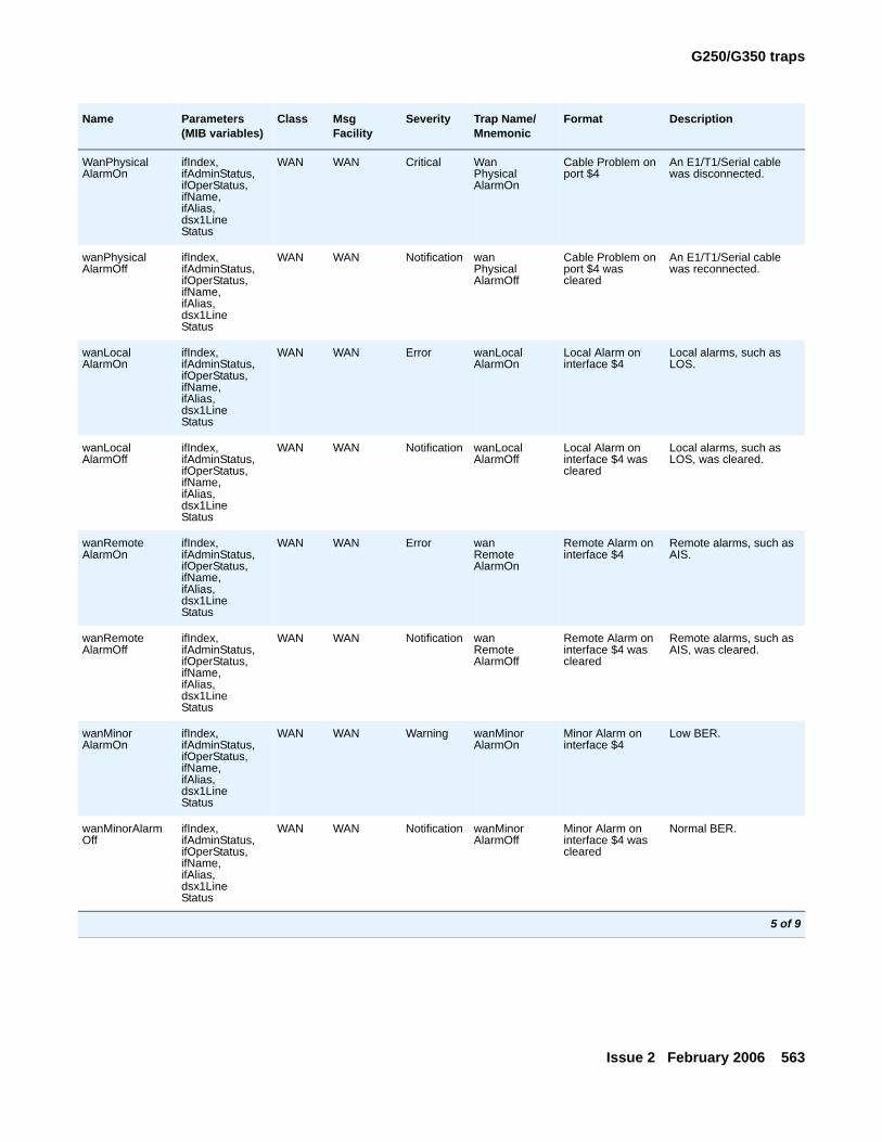
G250/G350 traps
Issue 2 February 2006 563
WanPhysicalAlarmOn
ifIndex,ifAdminStatus,ifOperStatus,ifName,ifAlias,dsx1LineStatus
WAN WAN Critical WanPhysicalAlarmOn
Cable Problem on port $4
An E1/T1/Serial cable was disconnected.
wanPhysicalAlarmOff
ifIndex,ifAdminStatus,ifOperStatus,ifName,ifAlias,dsx1LineStatus
WAN WAN Notification wanPhysicalAlarmOff
Cable Problem on port $4 was cleared
An E1/T1/Serial cable was reconnected.
wanLocalAlarmOn
ifIndex,ifAdminStatus,ifOperStatus,ifName,ifAlias,dsx1LineStatus
WAN WAN Error wanLocalAlarmOn
Local Alarm on interface $4
Local alarms, such as LOS.
wanLocalAlarmOff
ifIndex,ifAdminStatus,ifOperStatus,ifName,ifAlias,dsx1LineStatus
WAN WAN Notification wanLocalAlarmOff
Local Alarm on interface $4 was cleared
Local alarms, such as LOS, was cleared.
wanRemoteAlarmOn
ifIndex,ifAdminStatus,ifOperStatus,ifName,ifAlias,dsx1LineStatus
WAN WAN Error wanRemoteAlarmOn
Remote Alarm on interface $4
Remote alarms, such as AIS.
wanRemoteAlarmOff
ifIndex,ifAdminStatus,ifOperStatus,ifName,ifAlias,dsx1LineStatus
WAN WAN Notification wanRemoteAlarmOff
Remote Alarm on interface $4 was cleared
Remote alarms, such as AIS, was cleared.
wanMinorAlarmOn
ifIndex,ifAdminStatus,ifOperStatus,ifName,ifAlias,dsx1LineStatus
WAN WAN Warning wanMinorAlarmOn
Minor Alarm on interface $4
Low BER.
wanMinorAlarmOff
ifIndex,ifAdminStatus,ifOperStatus,ifName,ifAlias,dsx1LineStatus
WAN WAN Notification wanMinorAlarmOff
Minor Alarm on interface $4 was cleared
Normal BER.
Name Parameters (MIB variables)
Class Msg Facility
Severity Trap Name/ Mnemonic
Format Description
5 of 9
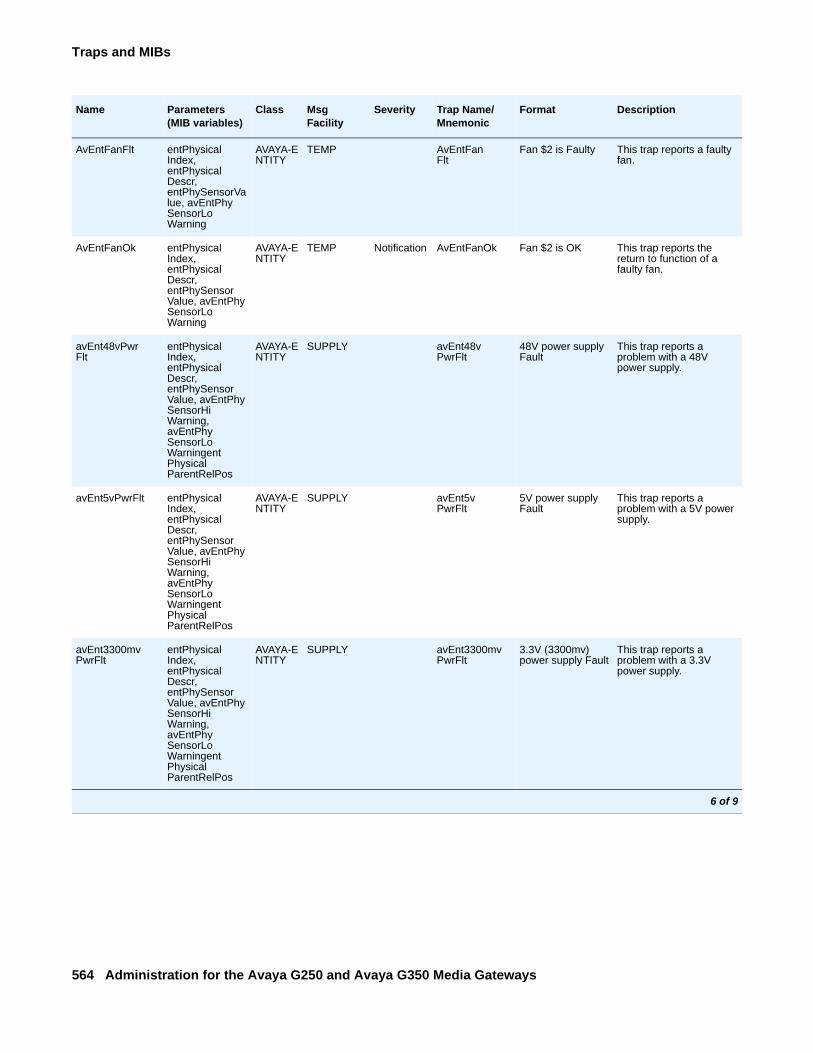
Traps and MIBs
564 Administration for the Avaya G250 and Avaya G350 Media Gateways
AvEntFanFlt entPhysicalIndex, entPhysicalDescr, entPhySensorValue, avEntPhySensorLoWarning
AVAYA-ENTITY
TEMP AvEntFanFlt
Fan $2 is Faulty This trap reports a faulty fan.
AvEntFanOk entPhysicalIndex, entPhysicalDescr, entPhySensorValue, avEntPhySensorLoWarning
AVAYA-ENTITY
TEMP Notification AvEntFanOk Fan $2 is OK This trap reports the return to function of a faulty fan.
avEnt48vPwrFlt
entPhysicalIndex, entPhysicalDescr, entPhySensorValue, avEntPhySensorHiWarning, avEntPhySensorLoWarningentPhysicalParentRelPos
AVAYA-ENTITY
SUPPLY avEnt48vPwrFlt
48V power supply Fault
This trap reports a problem with a 48V power supply.
avEnt5vPwrFlt entPhysicalIndex, entPhysicalDescr, entPhySensorValue, avEntPhySensorHiWarning, avEntPhySensorLoWarningentPhysicalParentRelPos
AVAYA-ENTITY
SUPPLY avEnt5vPwrFlt
5V power supply Fault
This trap reports a problem with a 5V power supply.
avEnt3300mvPwrFlt
entPhysicalIndex, entPhysicalDescr, entPhySensorValue, avEntPhySensorHiWarning, avEntPhySensorLoWarningentPhysicalParentRelPos
AVAYA-ENTITY
SUPPLY avEnt3300mvPwrFlt
3.3V (3300mv) power supply Fault
This trap reports a problem with a 3.3V power supply.
Name Parameters (MIB variables)
Class Msg Facility
Severity Trap Name/ Mnemonic
Format Description
6 of 9
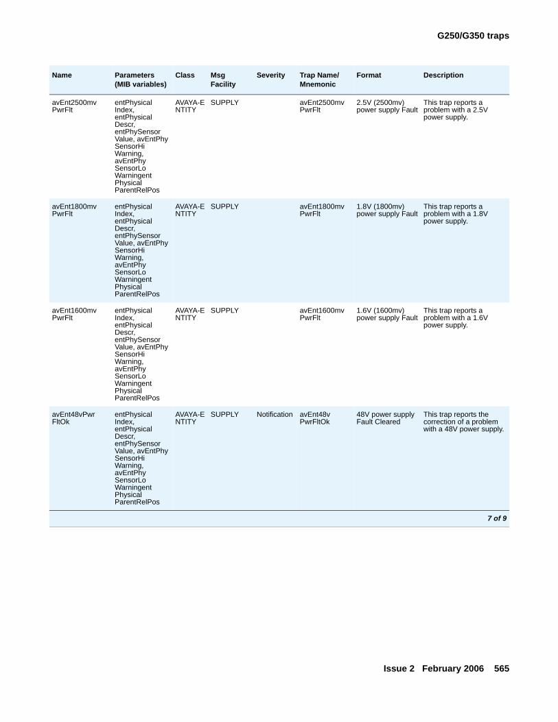
G250/G350 traps
Issue 2 February 2006 565
avEnt2500mvPwrFlt
entPhysicalIndex, entPhysicalDescr, entPhySensorValue, avEntPhySensorHiWarning, avEntPhySensorLoWarningentPhysicalParentRelPos
AVAYA-ENTITY
SUPPLY avEnt2500mvPwrFlt
2.5V (2500mv) power supply Fault
This trap reports a problem with a 2.5V power supply.
avEnt1800mvPwrFlt
entPhysicalIndex, entPhysicalDescr, entPhySensorValue, avEntPhySensorHiWarning, avEntPhySensorLoWarningentPhysicalParentRelPos
AVAYA-ENTITY
SUPPLY avEnt1800mvPwrFlt
1.8V (1800mv) power supply Fault
This trap reports a problem with a 1.8V power supply.
avEnt1600mvPwrFlt
entPhysicalIndex, entPhysicalDescr, entPhySensorValue, avEntPhySensorHiWarning, avEntPhySensorLoWarningentPhysicalParentRelPos
AVAYA-ENTITY
SUPPLY avEnt1600mvPwrFlt
1.6V (1600mv) power supply Fault
This trap reports a problem with a 1.6V power supply.
avEnt48vPwrFltOk
entPhysicalIndex, entPhysicalDescr, entPhySensorValue, avEntPhySensorHiWarning, avEntPhySensorLoWarningentPhysicalParentRelPos
AVAYA-ENTITY
SUPPLY Notification avEnt48vPwrFltOk
48V power supply Fault Cleared
This trap reports the correction of a problem with a 48V power supply.
Name Parameters (MIB variables)
Class Msg Facility
Severity Trap Name/ Mnemonic
Format Description
7 of 9
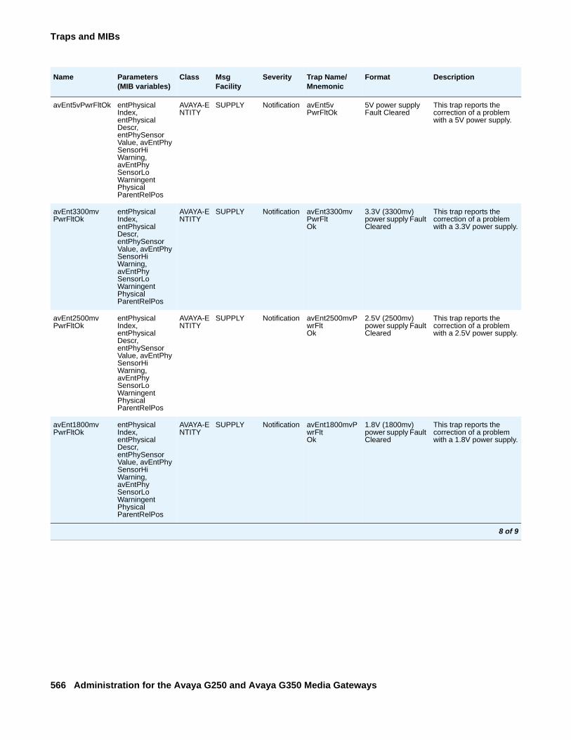
Traps and MIBs
566 Administration for the Avaya G250 and Avaya G350 Media Gateways
avEnt5vPwrFltOk entPhysicalIndex, entPhysicalDescr, entPhySensorValue, avEntPhySensorHiWarning, avEntPhySensorLoWarningentPhysicalParentRelPos
AVAYA-ENTITY
SUPPLY Notification avEnt5vPwrFltOk
5V power supply Fault Cleared
This trap reports the correction of a problem with a 5V power supply.
avEnt3300mvPwrFltOk
entPhysicalIndex, entPhysicalDescr, entPhySensorValue, avEntPhySensorHiWarning, avEntPhySensorLoWarningentPhysicalParentRelPos
AVAYA-ENTITY
SUPPLY Notification avEnt3300mvPwrFltOk
3.3V (3300mv) power supply Fault Cleared
This trap reports the correction of a problem with a 3.3V power supply.
avEnt2500mvPwrFltOk
entPhysicalIndex, entPhysicalDescr, entPhySensorValue, avEntPhySensorHiWarning, avEntPhySensorLoWarningentPhysicalParentRelPos
AVAYA-ENTITY
SUPPLY Notification avEnt2500mvPwrFltOk
2.5V (2500mv) power supply Fault Cleared
This trap reports the correction of a problem with a 2.5V power supply.
avEnt1800mvPwrFltOk
entPhysicalIndex, entPhysicalDescr, entPhySensorValue, avEntPhySensorHiWarning, avEntPhySensorLoWarningentPhysicalParentRelPos
AVAYA-ENTITY
SUPPLY Notification avEnt1800mvPwrFltOk
1.8V (1800mv) power supply Fault Cleared
This trap reports the correction of a problem with a 1.8V power supply.
Name Parameters (MIB variables)
Class Msg Facility
Severity Trap Name/ Mnemonic
Format Description
8 of 9
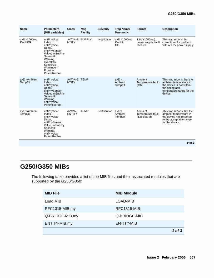
G250/G350 MIBs
Issue 2 February 2006 567
G250/G350 MIBsThe following table provides a list of the MIB files and their associated modules that are supported by the G250/G350:
avEnt1600mvPwrFltOk
entPhysicalIndex, entPhysicalDescr, entPhySensorValue, avEntPhySensorHiWarning, avEntPhySensorLoWarningentPhysicalParentRelPos
AVAYA-ENTITY
SUPPLY Notification avEnt1600mvPwrFltOk
1.6V (1600mv) power supply Fault Cleared
This trap reports the correction of a problem with a 1.6V power supply.
avEntAmbientTempFlt
entPhysicalIndex, entPhysicalDescr, entPhySensorValue, avEntPhySensorHiWarning, entPhysicalParentRelPos
AVAYA-ENTITY
TEMP avEntAmbientTempFlt
Ambient Temperature fault ($3)
This trap reports that the ambient temperature in the device is not within the acceptable temperature range for the device.
avEntAmbientTempOk
entPhysicalIndex, entPhysicalDescr, entPhySensorValue, avEntPhySensorHiWarning, entPhysicalParentRelPos
AVAYA-ENTITY
TEMP Notification avEntAmbientTempOk
Ambient Temperature fault ($3) cleared
This trap reports that the ambient temperature in the device has returned to the acceptable range for the device.
Name Parameters (MIB variables)
Class Msg Facility
Severity Trap Name/ Mnemonic
Format Description
9 of 9
MIB File MIB Module
Load.MIB LOAD-MIB
RFC1315-MIB.my RFC1315-MIB
Q-BRIDGE-MIB.my Q-BRIDGE-MIB
ENTITY-MIB.my ENTITY-MIB
1 of 3
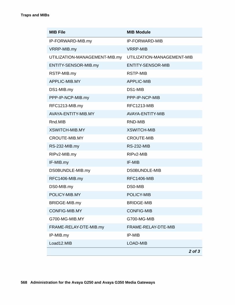
Traps and MIBs
568 Administration for the Avaya G250 and Avaya G350 Media Gateways
IP-FORWARD-MIB.my IP-FORWARD-MIB
VRRP-MIB.my VRRP-MIB
UTILIZATION-MANAGEMENT-MIB.my UTILIZATION-MANAGEMENT-MIB
ENTITY-SENSOR-MIB.my ENTITY-SENSOR-MIB
RSTP-MIB.my RSTP-MIB
APPLIC-MIB.MY APPLIC-MIB
DS1-MIB.my DS1-MIB
PPP-IP-NCP-MIB.my PPP-IP-NCP-MIB
RFC1213-MIB.my RFC1213-MIB
AVAYA-ENTITY-MIB.MY AVAYA-ENTITY-MIB
Rnd.MIB RND-MIB
XSWITCH-MIB.MY XSWITCH-MIB
CROUTE-MIB.MY CROUTE-MIB
RS-232-MIB.my RS-232-MIB
RIPv2-MIB.my RIPv2-MIB
IF-MIB.my IF-MIB
DS0BUNDLE-MIB.my DS0BUNDLE-MIB
RFC1406-MIB.my RFC1406-MIB
DS0-MIB.my DS0-MIB
POLICY-MIB.MY POLICY-MIB
BRIDGE-MIB.my BRIDGE-MIB
CONFIG-MIB.MY CONFIG-MIB
G700-MG-MIB.MY G700-MG-MIB
FRAME-RELAY-DTE-MIB.my FRAME-RELAY-DTE-MIB
IP-MIB.my IP-MIB
Load12.MIB LOAD-MIB
MIB File MIB Module
2 of 3
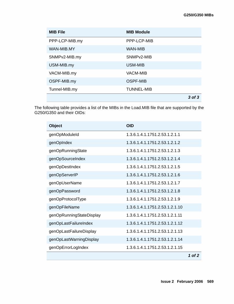
G250/G350 MIBs
Issue 2 February 2006 569
The following table provides a list of the MIBs in the Load.MIB file that are supported by the G250/G350 and their OIDs:
PPP-LCP-MIB.my PPP-LCP-MIB
WAN-MIB.MY WAN-MIB
SNMPv2-MIB.my SNMPv2-MIB
USM-MIB.my USM-MIB
VACM-MIB.my VACM-MIB
OSPF-MIB.my OSPF-MIB
Tunnel-MIB.my TUNNEL-MIB
Object OID
genOpModuleId 1.3.6.1.4.1.1751.2.53.1.2.1.1
genOpIndex 1.3.6.1.4.1.1751.2.53.1.2.1.2
genOpRunningState 1.3.6.1.4.1.1751.2.53.1.2.1.3
genOpSourceIndex 1.3.6.1.4.1.1751.2.53.1.2.1.4
genOpDestIndex 1.3.6.1.4.1.1751.2.53.1.2.1.5
genOpServerIP 1.3.6.1.4.1.1751.2.53.1.2.1.6
genOpUserName 1.3.6.1.4.1.1751.2.53.1.2.1.7
genOpPassword 1.3.6.1.4.1.1751.2.53.1.2.1.8
genOpProtocolType 1.3.6.1.4.1.1751.2.53.1.2.1.9
genOpFileName 1.3.6.1.4.1.1751.2.53.1.2.1.10
genOpRunningStateDisplay 1.3.6.1.4.1.1751.2.53.1.2.1.11
genOpLastFailureIndex 1.3.6.1.4.1.1751.2.53.1.2.1.12
genOpLastFailureDisplay 1.3.6.1.4.1.1751.2.53.1.2.1.13
genOpLastWarningDisplay 1.3.6.1.4.1.1751.2.53.1.2.1.14
genOpErrorLogIndex 1.3.6.1.4.1.1751.2.53.1.2.1.15
1 of 2
MIB File MIB Module
3 of 3
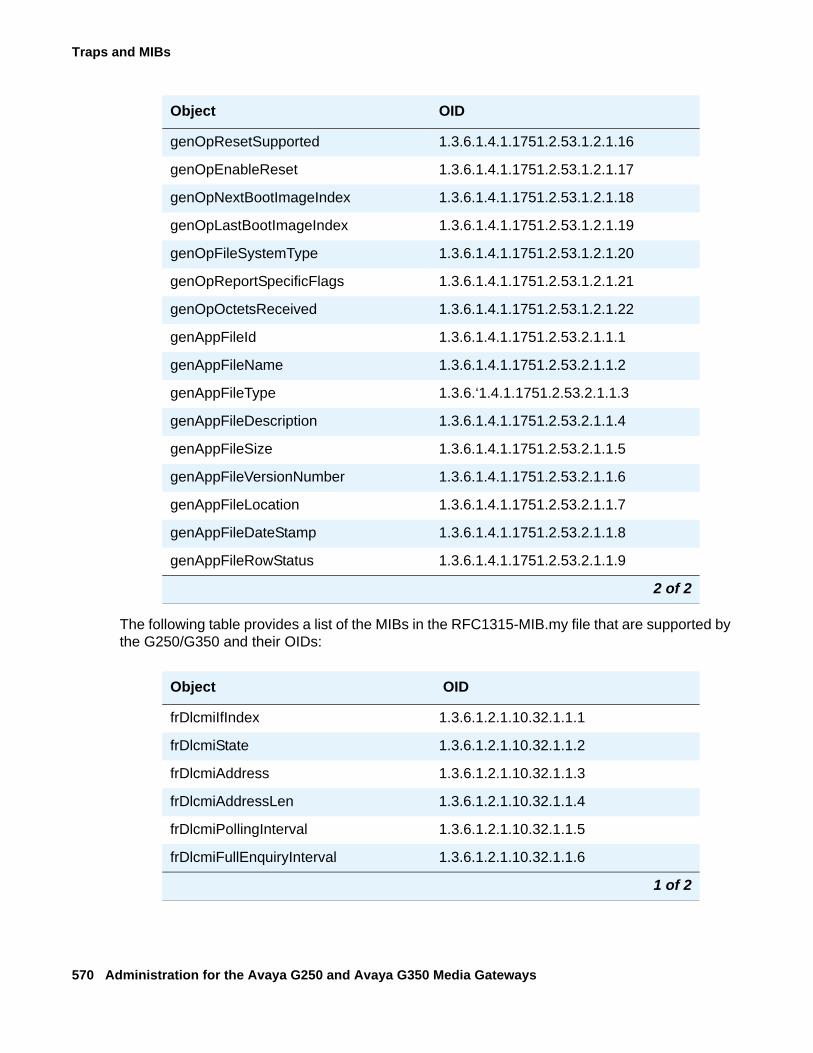
Traps and MIBs
570 Administration for the Avaya G250 and Avaya G350 Media Gateways
The following table provides a list of the MIBs in the RFC1315-MIB.my file that are supported by the G250/G350 and their OIDs:
genOpResetSupported 1.3.6.1.4.1.1751.2.53.1.2.1.16
genOpEnableReset 1.3.6.1.4.1.1751.2.53.1.2.1.17
genOpNextBootImageIndex 1.3.6.1.4.1.1751.2.53.1.2.1.18
genOpLastBootImageIndex 1.3.6.1.4.1.1751.2.53.1.2.1.19
genOpFileSystemType 1.3.6.1.4.1.1751.2.53.1.2.1.20
genOpReportSpecificFlags 1.3.6.1.4.1.1751.2.53.1.2.1.21
genOpOctetsReceived 1.3.6.1.4.1.1751.2.53.1.2.1.22
genAppFileId 1.3.6.1.4.1.1751.2.53.2.1.1.1
genAppFileName 1.3.6.1.4.1.1751.2.53.2.1.1.2
genAppFileType 1.3.6.‘1.4.1.1751.2.53.2.1.1.3
genAppFileDescription 1.3.6.1.4.1.1751.2.53.2.1.1.4
genAppFileSize 1.3.6.1.4.1.1751.2.53.2.1.1.5
genAppFileVersionNumber 1.3.6.1.4.1.1751.2.53.2.1.1.6
genAppFileLocation 1.3.6.1.4.1.1751.2.53.2.1.1.7
genAppFileDateStamp 1.3.6.1.4.1.1751.2.53.2.1.1.8
genAppFileRowStatus 1.3.6.1.4.1.1751.2.53.2.1.1.9
Object OID
frDlcmiIfIndex 1.3.6.1.2.1.10.32.1.1.1
frDlcmiState 1.3.6.1.2.1.10.32.1.1.2
frDlcmiAddress 1.3.6.1.2.1.10.32.1.1.3
frDlcmiAddressLen 1.3.6.1.2.1.10.32.1.1.4
frDlcmiPollingInterval 1.3.6.1.2.1.10.32.1.1.5
frDlcmiFullEnquiryInterval 1.3.6.1.2.1.10.32.1.1.6
1 of 2
Object OID
2 of 2
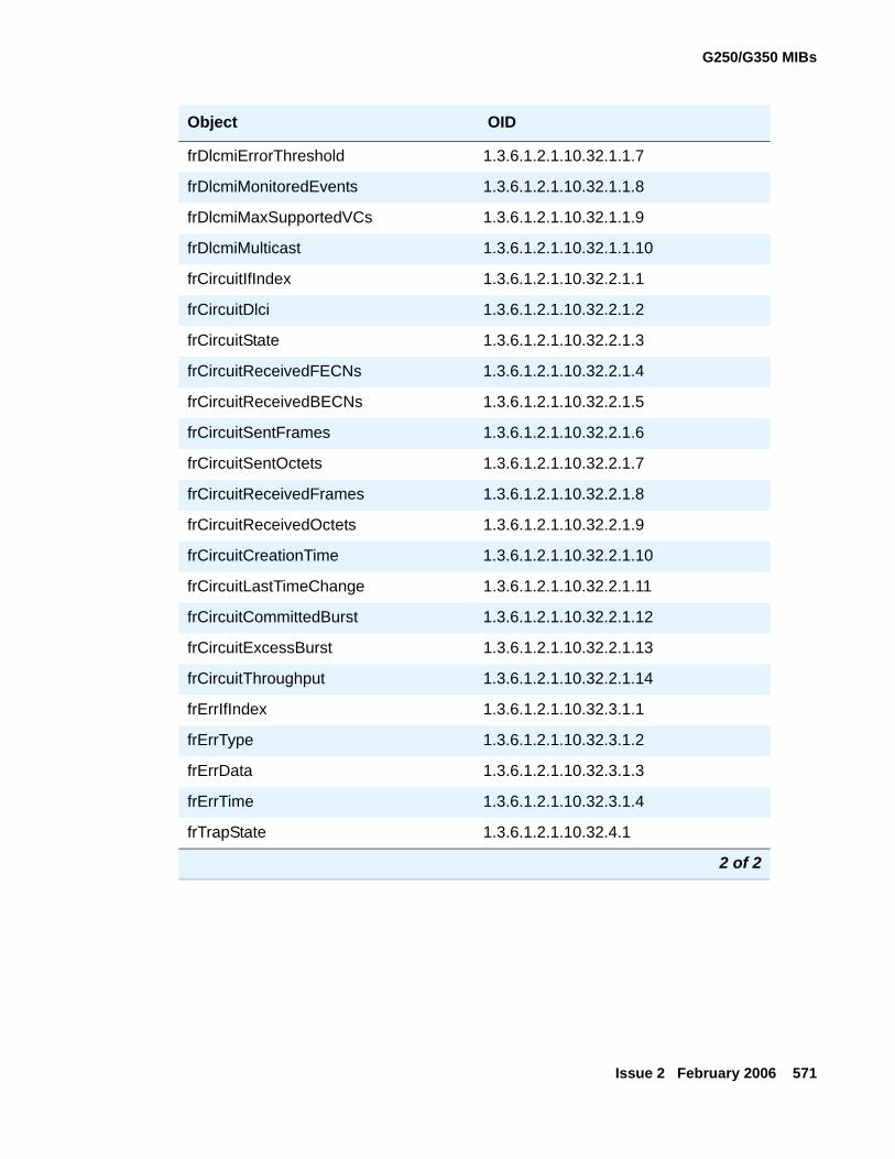
G250/G350 MIBs
Issue 2 February 2006 571
frDlcmiErrorThreshold 1.3.6.1.2.1.10.32.1.1.7
frDlcmiMonitoredEvents 1.3.6.1.2.1.10.32.1.1.8
frDlcmiMaxSupportedVCs 1.3.6.1.2.1.10.32.1.1.9
frDlcmiMulticast 1.3.6.1.2.1.10.32.1.1.10
frCircuitIfIndex 1.3.6.1.2.1.10.32.2.1.1
frCircuitDlci 1.3.6.1.2.1.10.32.2.1.2
frCircuitState 1.3.6.1.2.1.10.32.2.1.3
frCircuitReceivedFECNs 1.3.6.1.2.1.10.32.2.1.4
frCircuitReceivedBECNs 1.3.6.1.2.1.10.32.2.1.5
frCircuitSentFrames 1.3.6.1.2.1.10.32.2.1.6
frCircuitSentOctets 1.3.6.1.2.1.10.32.2.1.7
frCircuitReceivedFrames 1.3.6.1.2.1.10.32.2.1.8
frCircuitReceivedOctets 1.3.6.1.2.1.10.32.2.1.9
frCircuitCreationTime 1.3.6.1.2.1.10.32.2.1.10
frCircuitLastTimeChange 1.3.6.1.2.1.10.32.2.1.11
frCircuitCommittedBurst 1.3.6.1.2.1.10.32.2.1.12
frCircuitExcessBurst 1.3.6.1.2.1.10.32.2.1.13
frCircuitThroughput 1.3.6.1.2.1.10.32.2.1.14
frErrIfIndex 1.3.6.1.2.1.10.32.3.1.1
frErrType 1.3.6.1.2.1.10.32.3.1.2
frErrData 1.3.6.1.2.1.10.32.3.1.3
frErrTime 1.3.6.1.2.1.10.32.3.1.4
frTrapState 1.3.6.1.2.1.10.32.4.1
Object OID
2 of 2
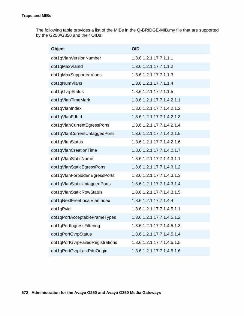
Traps and MIBs
572 Administration for the Avaya G250 and Avaya G350 Media Gateways
The following table provides a list of the MIBs in the Q-BRIDGE-MIB.my file that are supported by the G250/G350 and their OIDs:
Object OID
dot1qVlanVersionNumber 1.3.6.1.2.1.17.7.1.1.1
dot1qMaxVlanId 1.3.6.1.2.1.17.7.1.1.2
dot1qMaxSupportedVlans 1.3.6.1.2.1.17.7.1.1.3
dot1qNumVlans 1.3.6.1.2.1.17.7.1.1.4
dot1qGvrpStatus 1.3.6.1.2.1.17.7.1.1.5
dot1qVlanTimeMark 1.3.6.1.2.1.17.7.1.4.2.1.1
dot1qVlanIndex 1.3.6.1.2.1.17.7.1.4.2.1.2
dot1qVlanFdbId 1.3.6.1.2.1.17.7.1.4.2.1.3
dot1qVlanCurrentEgressPorts 1.3.6.1.2.1.17.7.1.4.2.1.4
dot1qVlanCurrentUntaggedPorts 1.3.6.1.2.1.17.7.1.4.2.1.5
dot1qVlanStatus 1.3.6.1.2.1.17.7.1.4.2.1.6
dot1qVlanCreationTime 1.3.6.1.2.1.17.7.1.4.2.1.7
dot1qVlanStaticName 1.3.6.1.2.1.17.7.1.4.3.1.1
dot1qVlanStaticEgressPorts 1.3.6.1.2.1.17.7.1.4.3.1.2
dot1qVlanForbiddenEgressPorts 1.3.6.1.2.1.17.7.1.4.3.1.3
dot1qVlanStaticUntaggedPorts 1.3.6.1.2.1.17.7.1.4.3.1.4
dot1qVlanStaticRowStatus 1.3.6.1.2.1.17.7.1.4.3.1.5
dot1qNextFreeLocalVlanIndex 1.3.6.1.2.1.17.7.1.4.4
dot1qPvid 1.3.6.1.2.1.17.7.1.4.5.1.1
dot1qPortAcceptableFrameTypes 1.3.6.1.2.1.17.7.1.4.5.1.2
dot1qPortIngressFiltering 1.3.6.1.2.1.17.7.1.4.5.1.3
dot1qPortGvrpStatus 1.3.6.1.2.1.17.7.1.4.5.1.4
dot1qPortGvrpFailedRegistrations 1.3.6.1.2.1.17.7.1.4.5.1.5
dot1qPortGvrpLastPduOrigin 1.3.6.1.2.1.17.7.1.4.5.1.6
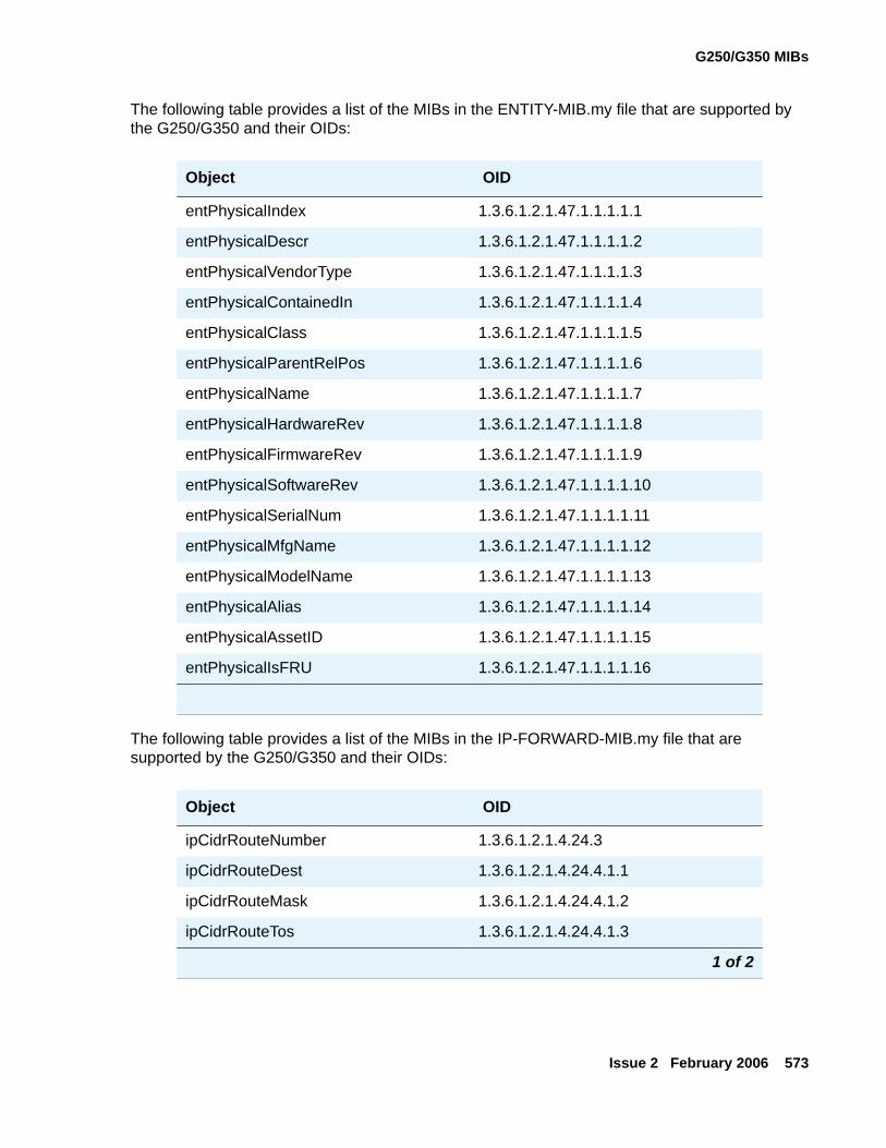
G250/G350 MIBs
Issue 2 February 2006 573
The following table provides a list of the MIBs in the ENTITY-MIB.my file that are supported by the G250/G350 and their OIDs:
The following table provides a list of the MIBs in the IP-FORWARD-MIB.my file that are supported by the G250/G350 and their OIDs:
Object OID
entPhysicalIndex 1.3.6.1.2.1.47.1.1.1.1.1
entPhysicalDescr 1.3.6.1.2.1.47.1.1.1.1.2
entPhysicalVendorType 1.3.6.1.2.1.47.1.1.1.1.3
entPhysicalContainedIn 1.3.6.1.2.1.47.1.1.1.1.4
entPhysicalClass 1.3.6.1.2.1.47.1.1.1.1.5
entPhysicalParentRelPos 1.3.6.1.2.1.47.1.1.1.1.6
entPhysicalName 1.3.6.1.2.1.47.1.1.1.1.7
entPhysicalHardwareRev 1.3.6.1.2.1.47.1.1.1.1.8
entPhysicalFirmwareRev 1.3.6.1.2.1.47.1.1.1.1.9
entPhysicalSoftwareRev 1.3.6.1.2.1.47.1.1.1.1.10
entPhysicalSerialNum 1.3.6.1.2.1.47.1.1.1.1.11
entPhysicalMfgName 1.3.6.1.2.1.47.1.1.1.1.12
entPhysicalModelName 1.3.6.1.2.1.47.1.1.1.1.13
entPhysicalAlias 1.3.6.1.2.1.47.1.1.1.1.14
entPhysicalAssetID 1.3.6.1.2.1.47.1.1.1.1.15
entPhysicalIsFRU 1.3.6.1.2.1.47.1.1.1.1.16
Object OID
ipCidrRouteNumber 1.3.6.1.2.1.4.24.3
ipCidrRouteDest 1.3.6.1.2.1.4.24.4.1.1
ipCidrRouteMask 1.3.6.1.2.1.4.24.4.1.2
ipCidrRouteTos 1.3.6.1.2.1.4.24.4.1.3
1 of 2
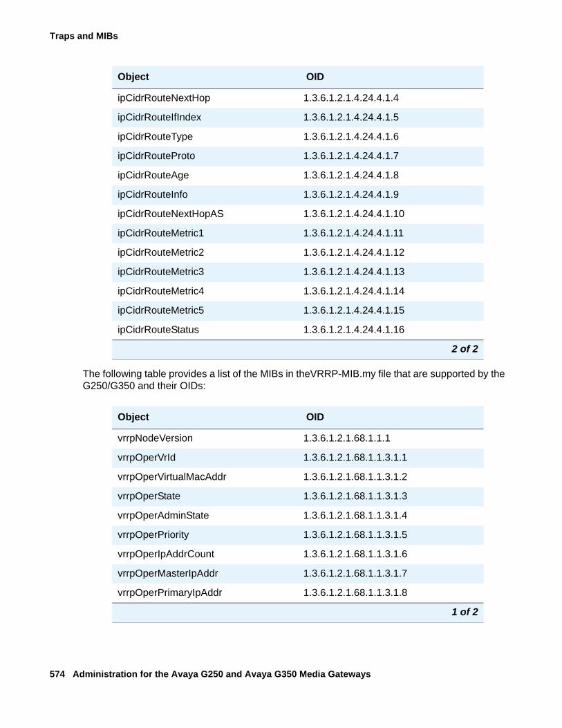
Traps and MIBs
574 Administration for the Avaya G250 and Avaya G350 Media Gateways
The following table provides a list of the MIBs in theVRRP-MIB.my file that are supported by the G250/G350 and their OIDs:
ipCidrRouteNextHop 1.3.6.1.2.1.4.24.4.1.4
ipCidrRouteIfIndex 1.3.6.1.2.1.4.24.4.1.5
ipCidrRouteType 1.3.6.1.2.1.4.24.4.1.6
ipCidrRouteProto 1.3.6.1.2.1.4.24.4.1.7
ipCidrRouteAge 1.3.6.1.2.1.4.24.4.1.8
ipCidrRouteInfo 1.3.6.1.2.1.4.24.4.1.9
ipCidrRouteNextHopAS 1.3.6.1.2.1.4.24.4.1.10
ipCidrRouteMetric1 1.3.6.1.2.1.4.24.4.1.11
ipCidrRouteMetric2 1.3.6.1.2.1.4.24.4.1.12
ipCidrRouteMetric3 1.3.6.1.2.1.4.24.4.1.13
ipCidrRouteMetric4 1.3.6.1.2.1.4.24.4.1.14
ipCidrRouteMetric5 1.3.6.1.2.1.4.24.4.1.15
ipCidrRouteStatus 1.3.6.1.2.1.4.24.4.1.16
Object OID
vrrpNodeVersion 1.3.6.1.2.1.68.1.1.1
vrrpOperVrId 1.3.6.1.2.1.68.1.1.3.1.1
vrrpOperVirtualMacAddr 1.3.6.1.2.1.68.1.1.3.1.2
vrrpOperState 1.3.6.1.2.1.68.1.1.3.1.3
vrrpOperAdminState 1.3.6.1.2.1.68.1.1.3.1.4
vrrpOperPriority 1.3.6.1.2.1.68.1.1.3.1.5
vrrpOperIpAddrCount 1.3.6.1.2.1.68.1.1.3.1.6
vrrpOperMasterIpAddr 1.3.6.1.2.1.68.1.1.3.1.7
vrrpOperPrimaryIpAddr 1.3.6.1.2.1.68.1.1.3.1.8
1 of 2
Object OID
2 of 2
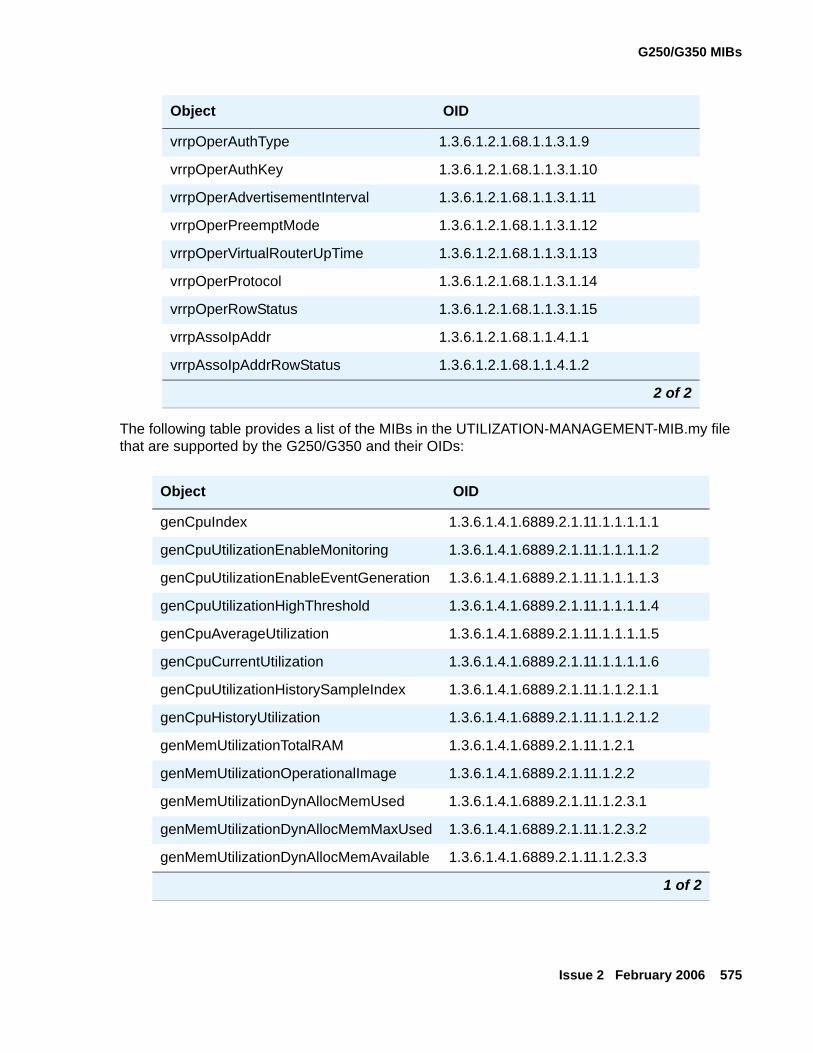
G250/G350 MIBs
Issue 2 February 2006 575
The following table provides a list of the MIBs in the UTILIZATION-MANAGEMENT-MIB.my file that are supported by the G250/G350 and their OIDs:
vrrpOperAuthType 1.3.6.1.2.1.68.1.1.3.1.9
vrrpOperAuthKey 1.3.6.1.2.1.68.1.1.3.1.10
vrrpOperAdvertisementInterval 1.3.6.1.2.1.68.1.1.3.1.11
vrrpOperPreemptMode 1.3.6.1.2.1.68.1.1.3.1.12
vrrpOperVirtualRouterUpTime 1.3.6.1.2.1.68.1.1.3.1.13
vrrpOperProtocol 1.3.6.1.2.1.68.1.1.3.1.14
vrrpOperRowStatus 1.3.6.1.2.1.68.1.1.3.1.15
vrrpAssoIpAddr 1.3.6.1.2.1.68.1.1.4.1.1
vrrpAssoIpAddrRowStatus 1.3.6.1.2.1.68.1.1.4.1.2
Object OID
genCpuIndex 1.3.6.1.4.1.6889.2.1.11.1.1.1.1.1
genCpuUtilizationEnableMonitoring 1.3.6.1.4.1.6889.2.1.11.1.1.1.1.2
genCpuUtilizationEnableEventGeneration 1.3.6.1.4.1.6889.2.1.11.1.1.1.1.3
genCpuUtilizationHighThreshold 1.3.6.1.4.1.6889.2.1.11.1.1.1.1.4
genCpuAverageUtilization 1.3.6.1.4.1.6889.2.1.11.1.1.1.1.5
genCpuCurrentUtilization 1.3.6.1.4.1.6889.2.1.11.1.1.1.1.6
genCpuUtilizationHistorySampleIndex 1.3.6.1.4.1.6889.2.1.11.1.1.2.1.1
genCpuHistoryUtilization 1.3.6.1.4.1.6889.2.1.11.1.1.2.1.2
genMemUtilizationTotalRAM 1.3.6.1.4.1.6889.2.1.11.1.2.1
genMemUtilizationOperationalImage 1.3.6.1.4.1.6889.2.1.11.1.2.2
genMemUtilizationDynAllocMemUsed 1.3.6.1.4.1.6889.2.1.11.1.2.3.1
genMemUtilizationDynAllocMemMaxUsed 1.3.6.1.4.1.6889.2.1.11.1.2.3.2
genMemUtilizationDynAllocMemAvailable 1.3.6.1.4.1.6889.2.1.11.1.2.3.3
1 of 2
Object OID
2 of 2
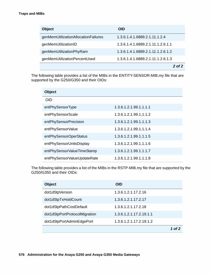
Traps and MIBs
576 Administration for the Avaya G250 and Avaya G350 Media Gateways
The following table provides a list of the MIBs in the ENTITY-SENSOR-MIB.my file that are supported by the G250/G350 and their OIDs:
The following table provides a list of the MIBs in the RSTP-MIB.my file that are supported by the G250/G350 and their OIDs:
genMemUtilizationAllocationFailures 1.3.6.1.4.1.6889.2.1.11.1.2.4
genMemUtilizationID 1.3.6.1.4.1.6889.2.1.11.1.2.6.1.1
genMemUtilizationPhyRam 1.3.6.1.4.1.6889.2.1.11.1.2.6.1.2
genMemUtilizationPercentUsed 1.3.6.1.4.1.6889.2.1.11.1.2.6.1.3
Object
OID
entPhySensorType 1.3.6.1.2.1.99.1.1.1.1
entPhySensorScale 1.3.6.1.2.1.99.1.1.1.2
entPhySensorPrecision 1.3.6.1.2.1.99.1.1.1.3
entPhySensorValue 1.3.6.1.2.1.99.1.1.1.4
entPhySensorOperStatus 1.3.6.1.2.1.99.1.1.1.5
entPhySensorUnitsDisplay 1.3.6.1.2.1.99.1.1.1.6
entPhySensorValueTimeStamp 1.3.6.1.2.1.99.1.1.1.7
entPhySensorValueUpdateRate 1.3.6.1.2.1.99.1.1.1.8
Object OID
dot1dStpVersion 1.3.6.1.2.1.17.2.16
dot1dStpTxHoldCount 1.3.6.1.2.1.17.2.17
dot1dStpPathCostDefault 1.3.6.1.2.1.17.2.18
dot1dStpPortProtocolMigration 1.3.6.1.2.1.17.2.19.1.1
dot1dStpPortAdminEdgePort 1.3.6.1.2.1.17.2.19.1.2
1 of 2
Object OID
2 of 2
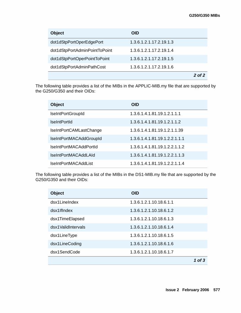
G250/G350 MIBs
Issue 2 February 2006 577
The following table provides a list of the MIBs in the APPLIC-MIB.my file that are supported by the G250/G350 and their OIDs:
The following table provides a list of the MIBs in the DS1-MIB.my file that are supported by the G250/G350 and their OIDs:
dot1dStpPortOperEdgePort 1.3.6.1.2.1.17.2.19.1.3
dot1dStpPortAdminPointToPoint 1.3.6.1.2.1.17.2.19.1.4
dot1dStpPortOperPointToPoint 1.3.6.1.2.1.17.2.19.1.5
dot1dStpPortAdminPathCost 1.3.6.1.2.1.17.2.19.1.6
Object OID
lseIntPortGroupId 1.3.6.1.4.1.81.19.1.2.1.1.1
lseIntPortId 1.3.6.1.4.1.81.19.1.2.1.1.2
lseIntPortCAMLastChange 1.3.6.1.4.1.81.19.1.2.1.1.39
lseIntPortMACAddGroupId 1.3.6.1.4.1.81.19.1.2.2.1.1.1
lseIntPortMACAddPortId 1.3.6.1.4.1.81.19.1.2.2.1.1.2
lseIntPortMACAddLAId 1.3.6.1.4.1.81.19.1.2.2.1.1.3
lseIntPortMACAddList 1.3.6.1.4.1.81.19.1.2.2.1.1.4
Object OID
dsx1LineIndex 1.3.6.1.2.1.10.18.6.1.1
dsx1IfIndex 1.3.6.1.2.1.10.18.6.1.2
dsx1TimeElapsed 1.3.6.1.2.1.10.18.6.1.3
dsx1ValidIntervals 1.3.6.1.2.1.10.18.6.1.4
dsx1LineType 1.3.6.1.2.1.10.18.6.1.5
dsx1LineCoding 1.3.6.1.2.1.10.18.6.1.6
dsx1SendCode 1.3.6.1.2.1.10.18.6.1.7
1 of 3
Object OID
2 of 2
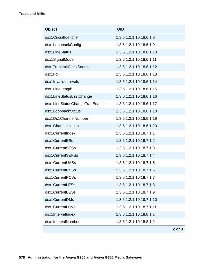
Traps and MIBs
578 Administration for the Avaya G250 and Avaya G350 Media Gateways
dsx1CircuitIdentifier 1.3.6.1.2.1.10.18.6.1.8
dsx1LoopbackConfig 1.3.6.1.2.1.10.18.6.1.9
dsx1LineStatus 1.3.6.1.2.1.10.18.6.1.10
dsx1SignalMode 1.3.6.1.2.1.10.18.6.1.11
dsx1TransmitClockSource 1.3.6.1.2.1.10.18.6.1.12
dsx1Fdl 1.3.6.1.2.1.10.18.6.1.13
dsx1InvalidIntervals 1.3.6.1.2.1.10.18.6.1.14
dsx1LineLength 1.3.6.1.2.1.10.18.6.1.15
dsx1LineStatusLastChange 1.3.6.1.2.1.10.18.6.1.16
dsx1LineStatusChangeTrapEnable 1.3.6.1.2.1.10.18.6.1.17
dsx1LoopbackStatus 1.3.6.1.2.1.10.18.6.1.18
dsx1Ds1ChannelNumber 1.3.6.1.2.1.10.18.6.1.19
dsx1Channelization 1.3.6.1.2.1.10.18.6.1.20
dsx1CurrentIndex 1.3.6.1.2.1.10.18.7.1.1
dsx1CurrentESs 1.3.6.1.2.1.10.18.7.1.2
dsx1CurrentSESs 1.3.6.1.2.1.10.18.7.1.3
dsx1CurrentSEFSs 1.3.6.1.2.1.10.18.7.1.4
dsx1CurrentUASs 1.3.6.1.2.1.10.18.7.1.5
dsx1CurrentCSSs 1.3.6.1.2.1.10.18.7.1.6
dsx1CurrentPCVs 1.3.6.1.2.1.10.18.7.1.7
dsx1CurrentLESs 1.3.6.1.2.1.10.18.7.1.8
dsx1CurrentBESs 1.3.6.1.2.1.10.18.7.1.9
dsx1CurrentDMs 1.3.6.1.2.1.10.18.7.1.10
dsx1CurrentLCVs 1.3.6.1.2.1.10.18.7.1.11
dsx1IntervalIndex 1.3.6.1.2.1.10.18.8.1.1
dsx1IntervalNumber 1.3.6.1.2.1.10.18.8.1.2
Object OID
2 of 3
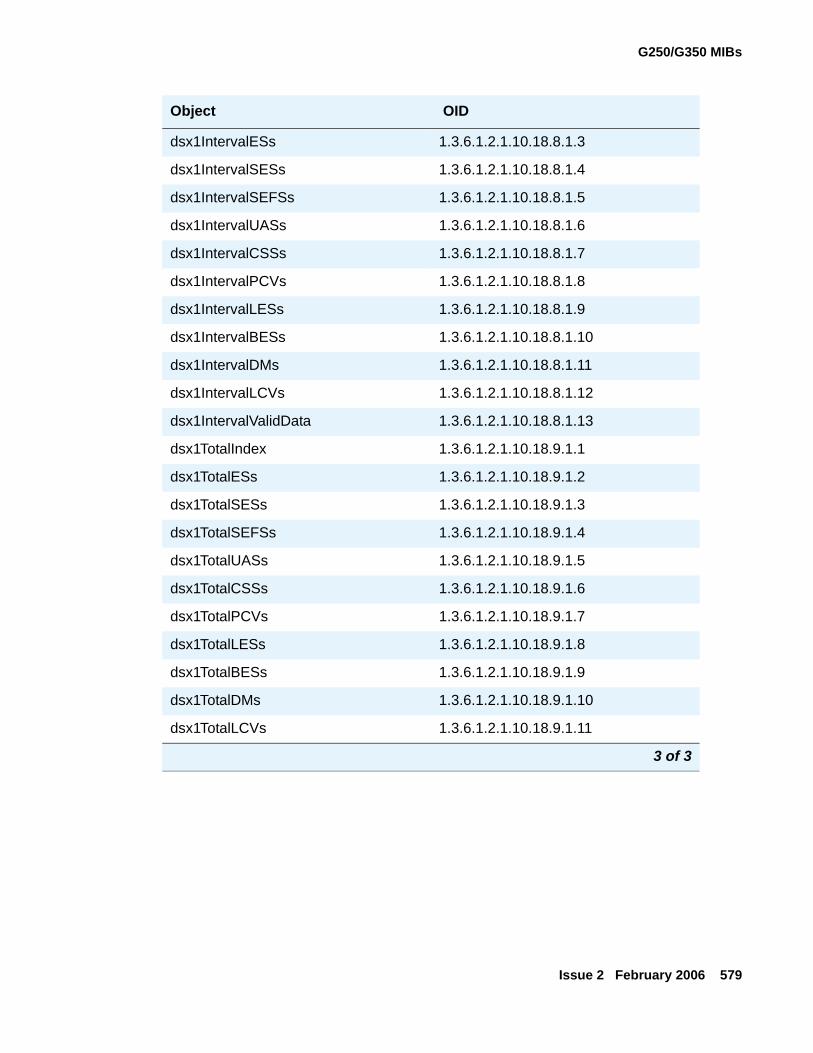
G250/G350 MIBs
Issue 2 February 2006 579
dsx1IntervalESs 1.3.6.1.2.1.10.18.8.1.3
dsx1IntervalSESs 1.3.6.1.2.1.10.18.8.1.4
dsx1IntervalSEFSs 1.3.6.1.2.1.10.18.8.1.5
dsx1IntervalUASs 1.3.6.1.2.1.10.18.8.1.6
dsx1IntervalCSSs 1.3.6.1.2.1.10.18.8.1.7
dsx1IntervalPCVs 1.3.6.1.2.1.10.18.8.1.8
dsx1IntervalLESs 1.3.6.1.2.1.10.18.8.1.9
dsx1IntervalBESs 1.3.6.1.2.1.10.18.8.1.10
dsx1IntervalDMs 1.3.6.1.2.1.10.18.8.1.11
dsx1IntervalLCVs 1.3.6.1.2.1.10.18.8.1.12
dsx1IntervalValidData 1.3.6.1.2.1.10.18.8.1.13
dsx1TotalIndex 1.3.6.1.2.1.10.18.9.1.1
dsx1TotalESs 1.3.6.1.2.1.10.18.9.1.2
dsx1TotalSESs 1.3.6.1.2.1.10.18.9.1.3
dsx1TotalSEFSs 1.3.6.1.2.1.10.18.9.1.4
dsx1TotalUASs 1.3.6.1.2.1.10.18.9.1.5
dsx1TotalCSSs 1.3.6.1.2.1.10.18.9.1.6
dsx1TotalPCVs 1.3.6.1.2.1.10.18.9.1.7
dsx1TotalLESs 1.3.6.1.2.1.10.18.9.1.8
dsx1TotalBESs 1.3.6.1.2.1.10.18.9.1.9
dsx1TotalDMs 1.3.6.1.2.1.10.18.9.1.10
dsx1TotalLCVs 1.3.6.1.2.1.10.18.9.1.11
Object OID
3 of 3
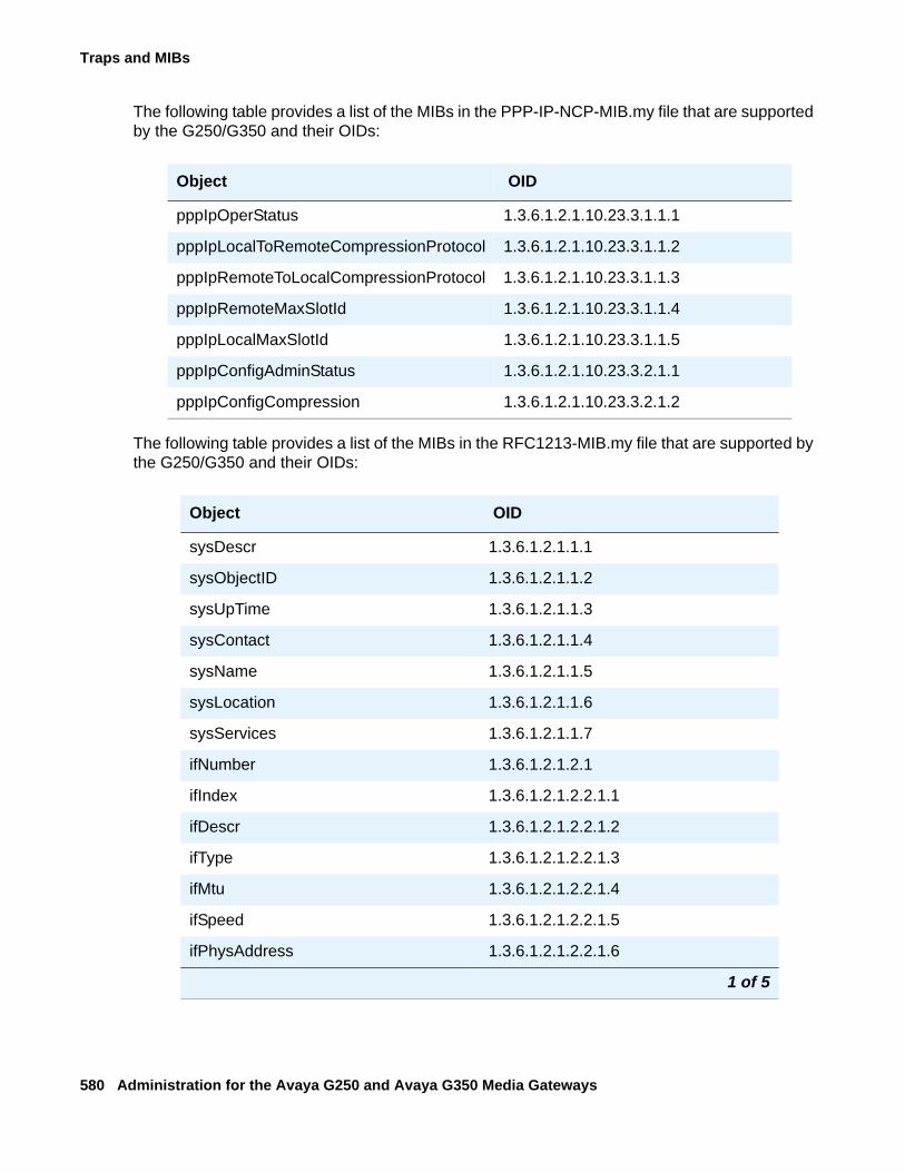
Traps and MIBs
580 Administration for the Avaya G250 and Avaya G350 Media Gateways
The following table provides a list of the MIBs in the PPP-IP-NCP-MIB.my file that are supported by the G250/G350 and their OIDs:
The following table provides a list of the MIBs in the RFC1213-MIB.my file that are supported by the G250/G350 and their OIDs:
Object OID
pppIpOperStatus 1.3.6.1.2.1.10.23.3.1.1.1
pppIpLocalToRemoteCompressionProtocol 1.3.6.1.2.1.10.23.3.1.1.2
pppIpRemoteToLocalCompressionProtocol 1.3.6.1.2.1.10.23.3.1.1.3
pppIpRemoteMaxSlotId 1.3.6.1.2.1.10.23.3.1.1.4
pppIpLocalMaxSlotId 1.3.6.1.2.1.10.23.3.1.1.5
pppIpConfigAdminStatus 1.3.6.1.2.1.10.23.3.2.1.1
pppIpConfigCompression 1.3.6.1.2.1.10.23.3.2.1.2
Object OID
sysDescr 1.3.6.1.2.1.1.1
sysObjectID 1.3.6.1.2.1.1.2
sysUpTime 1.3.6.1.2.1.1.3
sysContact 1.3.6.1.2.1.1.4
sysName 1.3.6.1.2.1.1.5
sysLocation 1.3.6.1.2.1.1.6
sysServices 1.3.6.1.2.1.1.7
ifNumber 1.3.6.1.2.1.2.1
ifIndex 1.3.6.1.2.1.2.2.1.1
ifDescr 1.3.6.1.2.1.2.2.1.2
ifType 1.3.6.1.2.1.2.2.1.3
ifMtu 1.3.6.1.2.1.2.2.1.4
ifSpeed 1.3.6.1.2.1.2.2.1.5
ifPhysAddress 1.3.6.1.2.1.2.2.1.6
1 of 5
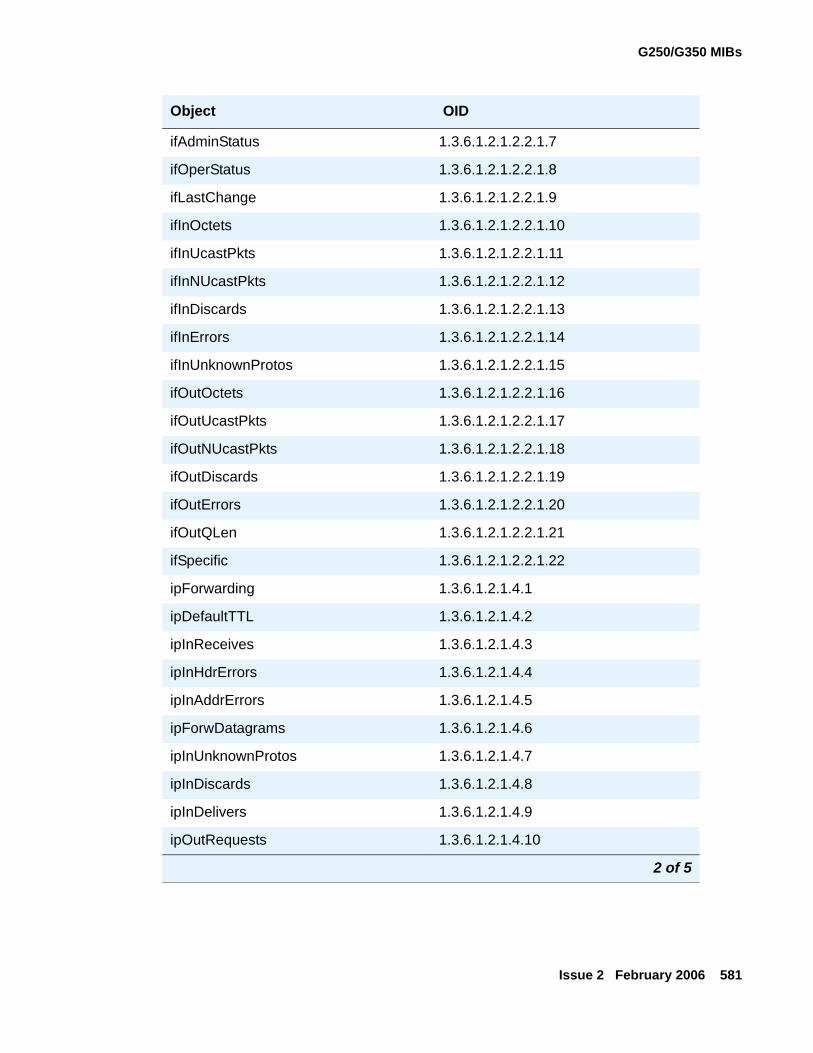
G250/G350 MIBs
Issue 2 February 2006 581
ifAdminStatus 1.3.6.1.2.1.2.2.1.7
ifOperStatus 1.3.6.1.2.1.2.2.1.8
ifLastChange 1.3.6.1.2.1.2.2.1.9
ifInOctets 1.3.6.1.2.1.2.2.1.10
ifInUcastPkts 1.3.6.1.2.1.2.2.1.11
ifInNUcastPkts 1.3.6.1.2.1.2.2.1.12
ifInDiscards 1.3.6.1.2.1.2.2.1.13
ifInErrors 1.3.6.1.2.1.2.2.1.14
ifInUnknownProtos 1.3.6.1.2.1.2.2.1.15
ifOutOctets 1.3.6.1.2.1.2.2.1.16
ifOutUcastPkts 1.3.6.1.2.1.2.2.1.17
ifOutNUcastPkts 1.3.6.1.2.1.2.2.1.18
ifOutDiscards 1.3.6.1.2.1.2.2.1.19
ifOutErrors 1.3.6.1.2.1.2.2.1.20
ifOutQLen 1.3.6.1.2.1.2.2.1.21
ifSpecific 1.3.6.1.2.1.2.2.1.22
ipForwarding 1.3.6.1.2.1.4.1
ipDefaultTTL 1.3.6.1.2.1.4.2
ipInReceives 1.3.6.1.2.1.4.3
ipInHdrErrors 1.3.6.1.2.1.4.4
ipInAddrErrors 1.3.6.1.2.1.4.5
ipForwDatagrams 1.3.6.1.2.1.4.6
ipInUnknownProtos 1.3.6.1.2.1.4.7
ipInDiscards 1.3.6.1.2.1.4.8
ipInDelivers 1.3.6.1.2.1.4.9
ipOutRequests 1.3.6.1.2.1.4.10
Object OID
2 of 5
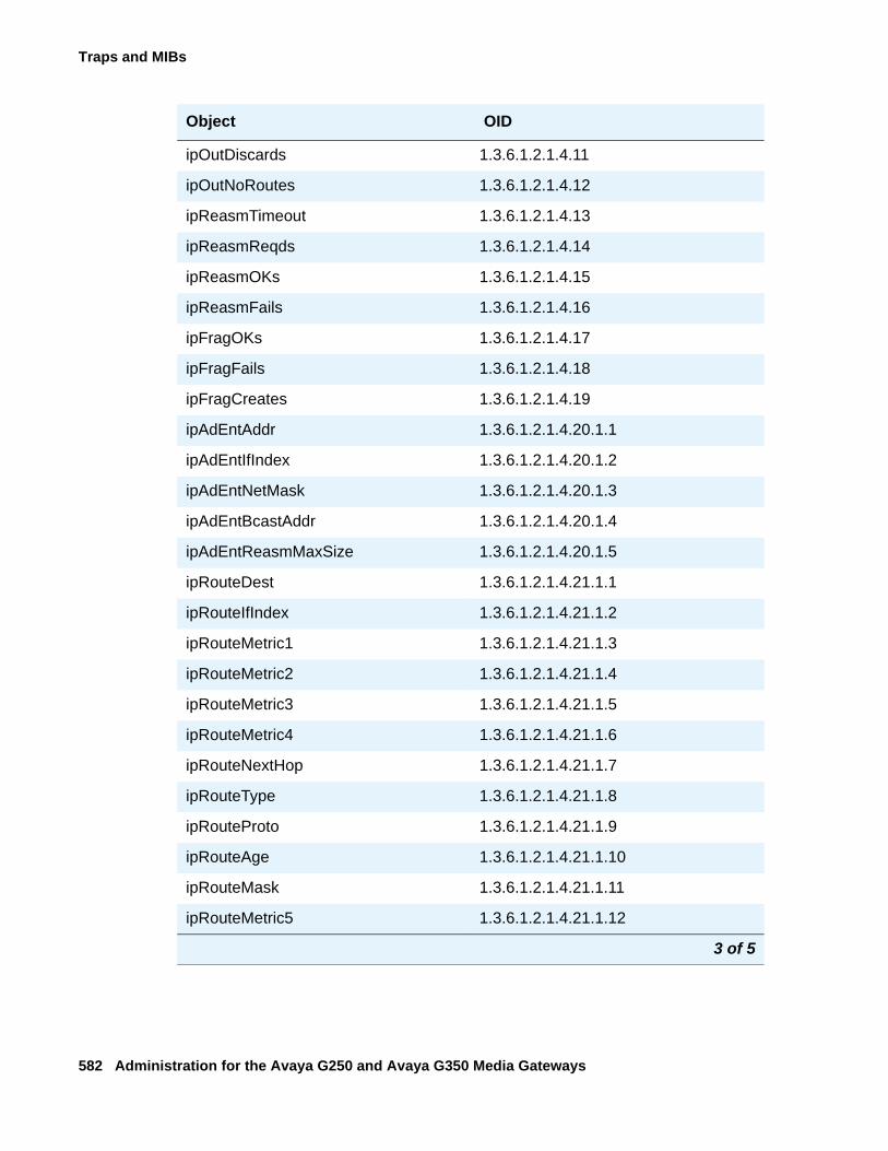
Traps and MIBs
582 Administration for the Avaya G250 and Avaya G350 Media Gateways
ipOutDiscards 1.3.6.1.2.1.4.11
ipOutNoRoutes 1.3.6.1.2.1.4.12
ipReasmTimeout 1.3.6.1.2.1.4.13
ipReasmReqds 1.3.6.1.2.1.4.14
ipReasmOKs 1.3.6.1.2.1.4.15
ipReasmFails 1.3.6.1.2.1.4.16
ipFragOKs 1.3.6.1.2.1.4.17
ipFragFails 1.3.6.1.2.1.4.18
ipFragCreates 1.3.6.1.2.1.4.19
ipAdEntAddr 1.3.6.1.2.1.4.20.1.1
ipAdEntIfIndex 1.3.6.1.2.1.4.20.1.2
ipAdEntNetMask 1.3.6.1.2.1.4.20.1.3
ipAdEntBcastAddr 1.3.6.1.2.1.4.20.1.4
ipAdEntReasmMaxSize 1.3.6.1.2.1.4.20.1.5
ipRouteDest 1.3.6.1.2.1.4.21.1.1
ipRouteIfIndex 1.3.6.1.2.1.4.21.1.2
ipRouteMetric1 1.3.6.1.2.1.4.21.1.3
ipRouteMetric2 1.3.6.1.2.1.4.21.1.4
ipRouteMetric3 1.3.6.1.2.1.4.21.1.5
ipRouteMetric4 1.3.6.1.2.1.4.21.1.6
ipRouteNextHop 1.3.6.1.2.1.4.21.1.7
ipRouteType 1.3.6.1.2.1.4.21.1.8
ipRouteProto 1.3.6.1.2.1.4.21.1.9
ipRouteAge 1.3.6.1.2.1.4.21.1.10
ipRouteMask 1.3.6.1.2.1.4.21.1.11
ipRouteMetric5 1.3.6.1.2.1.4.21.1.12
Object OID
3 of 5
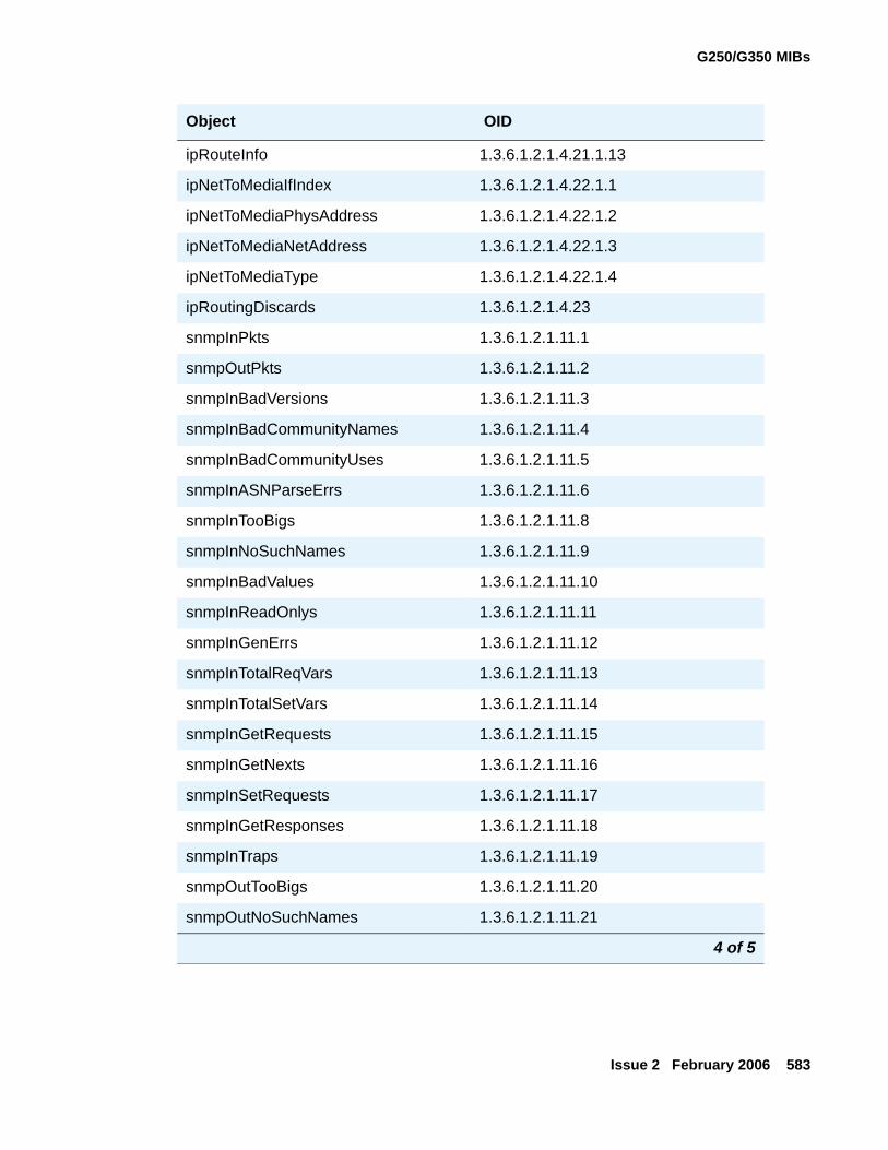
G250/G350 MIBs
Issue 2 February 2006 583
ipRouteInfo 1.3.6.1.2.1.4.21.1.13
ipNetToMediaIfIndex 1.3.6.1.2.1.4.22.1.1
ipNetToMediaPhysAddress 1.3.6.1.2.1.4.22.1.2
ipNetToMediaNetAddress 1.3.6.1.2.1.4.22.1.3
ipNetToMediaType 1.3.6.1.2.1.4.22.1.4
ipRoutingDiscards 1.3.6.1.2.1.4.23
snmpInPkts 1.3.6.1.2.1.11.1
snmpOutPkts 1.3.6.1.2.1.11.2
snmpInBadVersions 1.3.6.1.2.1.11.3
snmpInBadCommunityNames 1.3.6.1.2.1.11.4
snmpInBadCommunityUses 1.3.6.1.2.1.11.5
snmpInASNParseErrs 1.3.6.1.2.1.11.6
snmpInTooBigs 1.3.6.1.2.1.11.8
snmpInNoSuchNames 1.3.6.1.2.1.11.9
snmpInBadValues 1.3.6.1.2.1.11.10
snmpInReadOnlys 1.3.6.1.2.1.11.11
snmpInGenErrs 1.3.6.1.2.1.11.12
snmpInTotalReqVars 1.3.6.1.2.1.11.13
snmpInTotalSetVars 1.3.6.1.2.1.11.14
snmpInGetRequests 1.3.6.1.2.1.11.15
snmpInGetNexts 1.3.6.1.2.1.11.16
snmpInSetRequests 1.3.6.1.2.1.11.17
snmpInGetResponses 1.3.6.1.2.1.11.18
snmpInTraps 1.3.6.1.2.1.11.19
snmpOutTooBigs 1.3.6.1.2.1.11.20
snmpOutNoSuchNames 1.3.6.1.2.1.11.21
Object OID
4 of 5
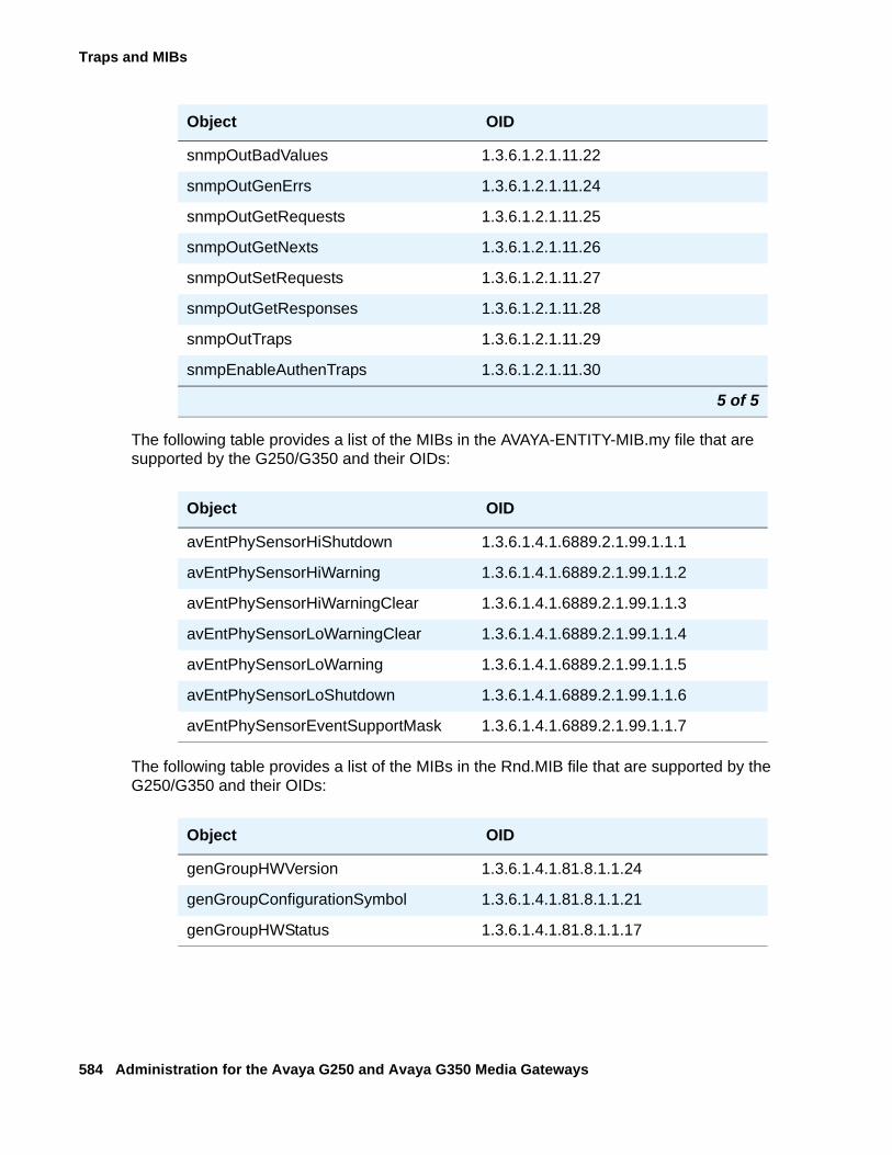
Traps and MIBs
584 Administration for the Avaya G250 and Avaya G350 Media Gateways
The following table provides a list of the MIBs in the AVAYA-ENTITY-MIB.my file that are supported by the G250/G350 and their OIDs:
The following table provides a list of the MIBs in the Rnd.MIB file that are supported by the G250/G350 and their OIDs:
snmpOutBadValues 1.3.6.1.2.1.11.22
snmpOutGenErrs 1.3.6.1.2.1.11.24
snmpOutGetRequests 1.3.6.1.2.1.11.25
snmpOutGetNexts 1.3.6.1.2.1.11.26
snmpOutSetRequests 1.3.6.1.2.1.11.27
snmpOutGetResponses 1.3.6.1.2.1.11.28
snmpOutTraps 1.3.6.1.2.1.11.29
snmpEnableAuthenTraps 1.3.6.1.2.1.11.30
Object OID
avEntPhySensorHiShutdown 1.3.6.1.4.1.6889.2.1.99.1.1.1
avEntPhySensorHiWarning 1.3.6.1.4.1.6889.2.1.99.1.1.2
avEntPhySensorHiWarningClear 1.3.6.1.4.1.6889.2.1.99.1.1.3
avEntPhySensorLoWarningClear 1.3.6.1.4.1.6889.2.1.99.1.1.4
avEntPhySensorLoWarning 1.3.6.1.4.1.6889.2.1.99.1.1.5
avEntPhySensorLoShutdown 1.3.6.1.4.1.6889.2.1.99.1.1.6
avEntPhySensorEventSupportMask 1.3.6.1.4.1.6889.2.1.99.1.1.7
Object OID
genGroupHWVersion 1.3.6.1.4.1.81.8.1.1.24
genGroupConfigurationSymbol 1.3.6.1.4.1.81.8.1.1.21
genGroupHWStatus 1.3.6.1.4.1.81.8.1.1.17
Object OID
5 of 5
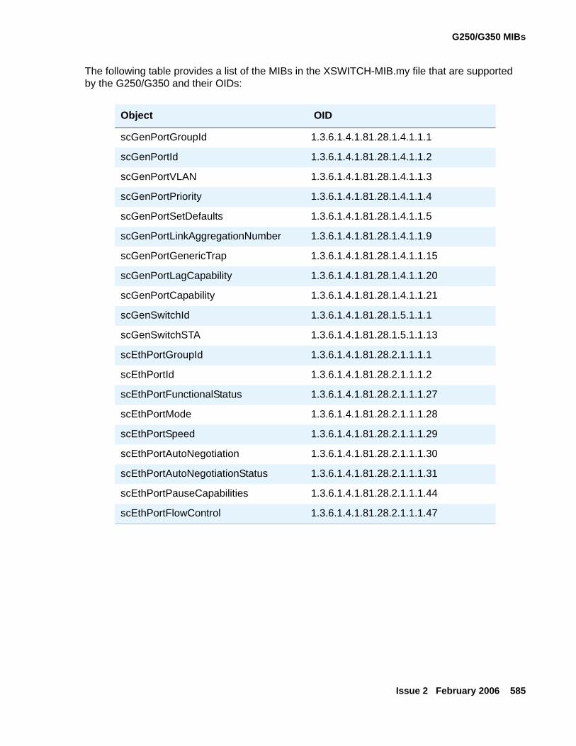
G250/G350 MIBs
Issue 2 February 2006 585
The following table provides a list of the MIBs in the XSWITCH-MIB.my file that are supported by the G250/G350 and their OIDs:
Object OID
scGenPortGroupId 1.3.6.1.4.1.81.28.1.4.1.1.1
scGenPortId 1.3.6.1.4.1.81.28.1.4.1.1.2
scGenPortVLAN 1.3.6.1.4.1.81.28.1.4.1.1.3
scGenPortPriority 1.3.6.1.4.1.81.28.1.4.1.1.4
scGenPortSetDefaults 1.3.6.1.4.1.81.28.1.4.1.1.5
scGenPortLinkAggregationNumber 1.3.6.1.4.1.81.28.1.4.1.1.9
scGenPortGenericTrap 1.3.6.1.4.1.81.28.1.4.1.1.15
scGenPortLagCapability 1.3.6.1.4.1.81.28.1.4.1.1.20
scGenPortCapability 1.3.6.1.4.1.81.28.1.4.1.1.21
scGenSwitchId 1.3.6.1.4.1.81.28.1.5.1.1.1
scGenSwitchSTA 1.3.6.1.4.1.81.28.1.5.1.1.13
scEthPortGroupId 1.3.6.1.4.1.81.28.2.1.1.1.1
scEthPortId 1.3.6.1.4.1.81.28.2.1.1.1.2
scEthPortFunctionalStatus 1.3.6.1.4.1.81.28.2.1.1.1.27
scEthPortMode 1.3.6.1.4.1.81.28.2.1.1.1.28
scEthPortSpeed 1.3.6.1.4.1.81.28.2.1.1.1.29
scEthPortAutoNegotiation 1.3.6.1.4.1.81.28.2.1.1.1.30
scEthPortAutoNegotiationStatus 1.3.6.1.4.1.81.28.2.1.1.1.31
scEthPortPauseCapabilities 1.3.6.1.4.1.81.28.2.1.1.1.44
scEthPortFlowControl 1.3.6.1.4.1.81.28.2.1.1.1.47
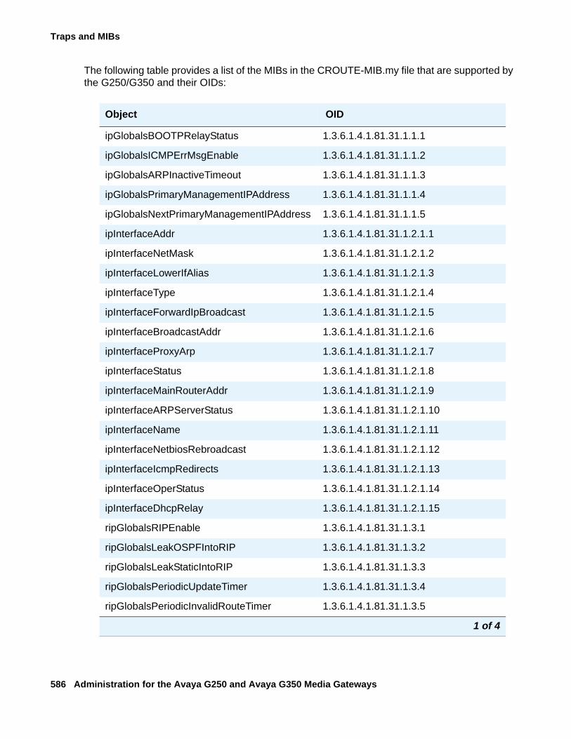
Traps and MIBs
586 Administration for the Avaya G250 and Avaya G350 Media Gateways
The following table provides a list of the MIBs in the CROUTE-MIB.my file that are supported by the G250/G350 and their OIDs:
Object OID
ipGlobalsBOOTPRelayStatus 1.3.6.1.4.1.81.31.1.1.1
ipGlobalsICMPErrMsgEnable 1.3.6.1.4.1.81.31.1.1.2
ipGlobalsARPInactiveTimeout 1.3.6.1.4.1.81.31.1.1.3
ipGlobalsPrimaryManagementIPAddress 1.3.6.1.4.1.81.31.1.1.4
ipGlobalsNextPrimaryManagementIPAddress 1.3.6.1.4.1.81.31.1.1.5
ipInterfaceAddr 1.3.6.1.4.1.81.31.1.2.1.1
ipInterfaceNetMask 1.3.6.1.4.1.81.31.1.2.1.2
ipInterfaceLowerIfAlias 1.3.6.1.4.1.81.31.1.2.1.3
ipInterfaceType 1.3.6.1.4.1.81.31.1.2.1.4
ipInterfaceForwardIpBroadcast 1.3.6.1.4.1.81.31.1.2.1.5
ipInterfaceBroadcastAddr 1.3.6.1.4.1.81.31.1.2.1.6
ipInterfaceProxyArp 1.3.6.1.4.1.81.31.1.2.1.7
ipInterfaceStatus 1.3.6.1.4.1.81.31.1.2.1.8
ipInterfaceMainRouterAddr 1.3.6.1.4.1.81.31.1.2.1.9
ipInterfaceARPServerStatus 1.3.6.1.4.1.81.31.1.2.1.10
ipInterfaceName 1.3.6.1.4.1.81.31.1.2.1.11
ipInterfaceNetbiosRebroadcast 1.3.6.1.4.1.81.31.1.2.1.12
ipInterfaceIcmpRedirects 1.3.6.1.4.1.81.31.1.2.1.13
ipInterfaceOperStatus 1.3.6.1.4.1.81.31.1.2.1.14
ipInterfaceDhcpRelay 1.3.6.1.4.1.81.31.1.2.1.15
ripGlobalsRIPEnable 1.3.6.1.4.1.81.31.1.3.1
ripGlobalsLeakOSPFIntoRIP 1.3.6.1.4.1.81.31.1.3.2
ripGlobalsLeakStaticIntoRIP 1.3.6.1.4.1.81.31.1.3.3
ripGlobalsPeriodicUpdateTimer 1.3.6.1.4.1.81.31.1.3.4
ripGlobalsPeriodicInvalidRouteTimer 1.3.6.1.4.1.81.31.1.3.5
1 of 4
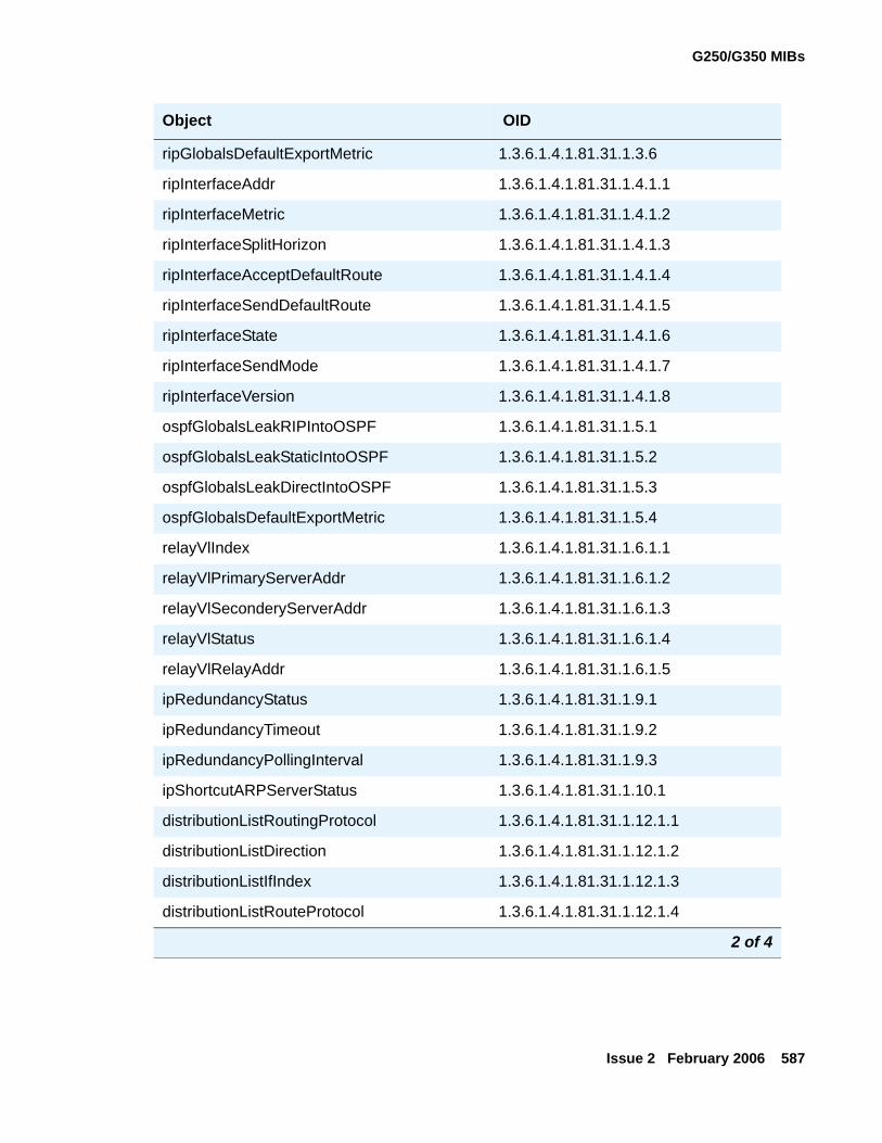
G250/G350 MIBs
Issue 2 February 2006 587
ripGlobalsDefaultExportMetric 1.3.6.1.4.1.81.31.1.3.6
ripInterfaceAddr 1.3.6.1.4.1.81.31.1.4.1.1
ripInterfaceMetric 1.3.6.1.4.1.81.31.1.4.1.2
ripInterfaceSplitHorizon 1.3.6.1.4.1.81.31.1.4.1.3
ripInterfaceAcceptDefaultRoute 1.3.6.1.4.1.81.31.1.4.1.4
ripInterfaceSendDefaultRoute 1.3.6.1.4.1.81.31.1.4.1.5
ripInterfaceState 1.3.6.1.4.1.81.31.1.4.1.6
ripInterfaceSendMode 1.3.6.1.4.1.81.31.1.4.1.7
ripInterfaceVersion 1.3.6.1.4.1.81.31.1.4.1.8
ospfGlobalsLeakRIPIntoOSPF 1.3.6.1.4.1.81.31.1.5.1
ospfGlobalsLeakStaticIntoOSPF 1.3.6.1.4.1.81.31.1.5.2
ospfGlobalsLeakDirectIntoOSPF 1.3.6.1.4.1.81.31.1.5.3
ospfGlobalsDefaultExportMetric 1.3.6.1.4.1.81.31.1.5.4
relayVlIndex 1.3.6.1.4.1.81.31.1.6.1.1
relayVlPrimaryServerAddr 1.3.6.1.4.1.81.31.1.6.1.2
relayVlSeconderyServerAddr 1.3.6.1.4.1.81.31.1.6.1.3
relayVlStatus 1.3.6.1.4.1.81.31.1.6.1.4
relayVlRelayAddr 1.3.6.1.4.1.81.31.1.6.1.5
ipRedundancyStatus 1.3.6.1.4.1.81.31.1.9.1
ipRedundancyTimeout 1.3.6.1.4.1.81.31.1.9.2
ipRedundancyPollingInterval 1.3.6.1.4.1.81.31.1.9.3
ipShortcutARPServerStatus 1.3.6.1.4.1.81.31.1.10.1
distributionListRoutingProtocol 1.3.6.1.4.1.81.31.1.12.1.1
distributionListDirection 1.3.6.1.4.1.81.31.1.12.1.2
distributionListIfIndex 1.3.6.1.4.1.81.31.1.12.1.3
distributionListRouteProtocol 1.3.6.1.4.1.81.31.1.12.1.4
Object OID
2 of 4
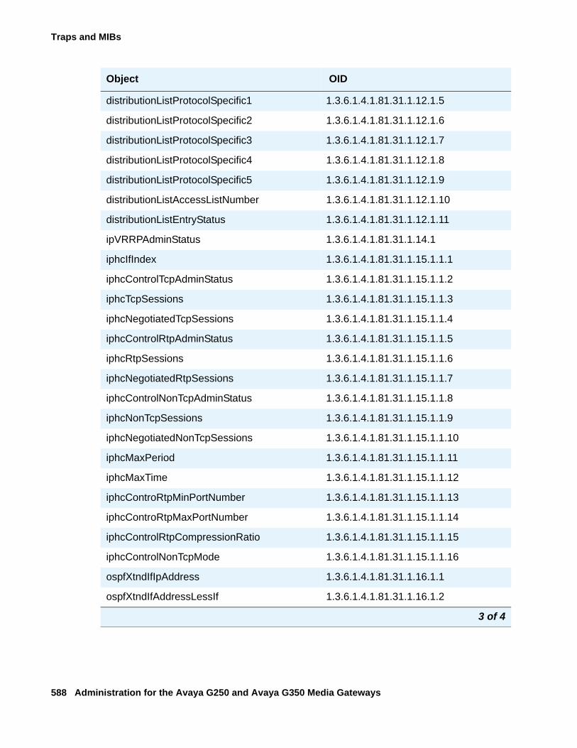
Traps and MIBs
588 Administration for the Avaya G250 and Avaya G350 Media Gateways
distributionListProtocolSpecific1 1.3.6.1.4.1.81.31.1.12.1.5
distributionListProtocolSpecific2 1.3.6.1.4.1.81.31.1.12.1.6
distributionListProtocolSpecific3 1.3.6.1.4.1.81.31.1.12.1.7
distributionListProtocolSpecific4 1.3.6.1.4.1.81.31.1.12.1.8
distributionListProtocolSpecific5 1.3.6.1.4.1.81.31.1.12.1.9
distributionListAccessListNumber 1.3.6.1.4.1.81.31.1.12.1.10
distributionListEntryStatus 1.3.6.1.4.1.81.31.1.12.1.11
ipVRRPAdminStatus 1.3.6.1.4.1.81.31.1.14.1
iphcIfIndex 1.3.6.1.4.1.81.31.1.15.1.1.1
iphcControlTcpAdminStatus 1.3.6.1.4.1.81.31.1.15.1.1.2
iphcTcpSessions 1.3.6.1.4.1.81.31.1.15.1.1.3
iphcNegotiatedTcpSessions 1.3.6.1.4.1.81.31.1.15.1.1.4
iphcControlRtpAdminStatus 1.3.6.1.4.1.81.31.1.15.1.1.5
iphcRtpSessions 1.3.6.1.4.1.81.31.1.15.1.1.6
iphcNegotiatedRtpSessions 1.3.6.1.4.1.81.31.1.15.1.1.7
iphcControlNonTcpAdminStatus 1.3.6.1.4.1.81.31.1.15.1.1.8
iphcNonTcpSessions 1.3.6.1.4.1.81.31.1.15.1.1.9
iphcNegotiatedNonTcpSessions 1.3.6.1.4.1.81.31.1.15.1.1.10
iphcMaxPeriod 1.3.6.1.4.1.81.31.1.15.1.1.11
iphcMaxTime 1.3.6.1.4.1.81.31.1.15.1.1.12
iphcControRtpMinPortNumber 1.3.6.1.4.1.81.31.1.15.1.1.13
iphcControRtpMaxPortNumber 1.3.6.1.4.1.81.31.1.15.1.1.14
iphcControlRtpCompressionRatio 1.3.6.1.4.1.81.31.1.15.1.1.15
iphcControlNonTcpMode 1.3.6.1.4.1.81.31.1.15.1.1.16
ospfXtndIfIpAddress 1.3.6.1.4.1.81.31.1.16.1.1
ospfXtndIfAddressLessIf 1.3.6.1.4.1.81.31.1.16.1.2
Object OID
3 of 4
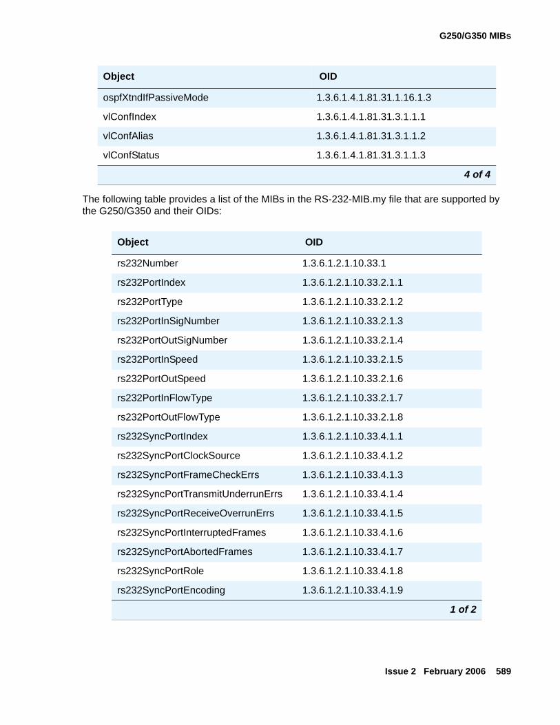
G250/G350 MIBs
Issue 2 February 2006 589
The following table provides a list of the MIBs in the RS-232-MIB.my file that are supported by the G250/G350 and their OIDs:
ospfXtndIfPassiveMode 1.3.6.1.4.1.81.31.1.16.1.3
vlConfIndex 1.3.6.1.4.1.81.31.3.1.1.1
vlConfAlias 1.3.6.1.4.1.81.31.3.1.1.2
vlConfStatus 1.3.6.1.4.1.81.31.3.1.1.3
Object OID
rs232Number 1.3.6.1.2.1.10.33.1
rs232PortIndex 1.3.6.1.2.1.10.33.2.1.1
rs232PortType 1.3.6.1.2.1.10.33.2.1.2
rs232PortInSigNumber 1.3.6.1.2.1.10.33.2.1.3
rs232PortOutSigNumber 1.3.6.1.2.1.10.33.2.1.4
rs232PortInSpeed 1.3.6.1.2.1.10.33.2.1.5
rs232PortOutSpeed 1.3.6.1.2.1.10.33.2.1.6
rs232PortInFlowType 1.3.6.1.2.1.10.33.2.1.7
rs232PortOutFlowType 1.3.6.1.2.1.10.33.2.1.8
rs232SyncPortIndex 1.3.6.1.2.1.10.33.4.1.1
rs232SyncPortClockSource 1.3.6.1.2.1.10.33.4.1.2
rs232SyncPortFrameCheckErrs 1.3.6.1.2.1.10.33.4.1.3
rs232SyncPortTransmitUnderrunErrs 1.3.6.1.2.1.10.33.4.1.4
rs232SyncPortReceiveOverrunErrs 1.3.6.1.2.1.10.33.4.1.5
rs232SyncPortInterruptedFrames 1.3.6.1.2.1.10.33.4.1.6
rs232SyncPortAbortedFrames 1.3.6.1.2.1.10.33.4.1.7
rs232SyncPortRole 1.3.6.1.2.1.10.33.4.1.8
rs232SyncPortEncoding 1.3.6.1.2.1.10.33.4.1.9
1 of 2
Object OID
4 of 4
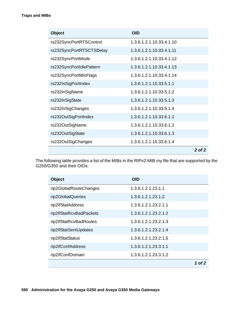
Traps and MIBs
590 Administration for the Avaya G250 and Avaya G350 Media Gateways
The following table provides a list of the MIBs in the RIPv2-MIB.my file that are supported by the G250/G350 and their OIDs:
rs232SyncPortRTSControl 1.3.6.1.2.1.10.33.4.1.10
rs232SyncPortRTSCTSDelay 1.3.6.1.2.1.10.33.4.1.11
rs232SyncPortMode 1.3.6.1.2.1.10.33.4.1.12
rs232SyncPortIdlePattern 1.3.6.1.2.1.10.33.4.1.13
rs232SyncPortMinFlags 1.3.6.1.2.1.10.33.4.1.14
rs232InSigPortIndex 1.3.6.1.2.1.10.33.5.1.1
rs232InSigName 1.3.6.1.2.1.10.33.5.1.2
rs232InSigState 1.3.6.1.2.1.10.33.5.1.3
rs232InSigChanges 1.3.6.1.2.1.10.33.5.1.4
rs232OutSigPortIndex 1.3.6.1.2.1.10.33.6.1.1
rs232OutSigName 1.3.6.1.2.1.10.33.6.1.2
rs232OutSigState 1.3.6.1.2.1.10.33.6.1.3
rs232OutSigChanges 1.3.6.1.2.1.10.33.6.1.4
Object OID
rip2GlobalRouteChanges 1.3.6.1.2.1.23.1.1
rip2GlobalQueries 1.3.6.1.2.1.23.1.2
rip2IfStatAddress 1.3.6.1.2.1.23.2.1.1
rip2IfStatRcvBadPackets 1.3.6.1.2.1.23.2.1.2
rip2IfStatRcvBadRoutes 1.3.6.1.2.1.23.2.1.3
rip2IfStatSentUpdates 1.3.6.1.2.1.23.2.1.4
rip2IfStatStatus 1.3.6.1.2.1.23.2.1.5
rip2IfConfAddress 1.3.6.1.2.1.23.3.1.1
rip2IfConfDomain 1.3.6.1.2.1.23.3.1.2
1 of 2
Object OID
2 of 2
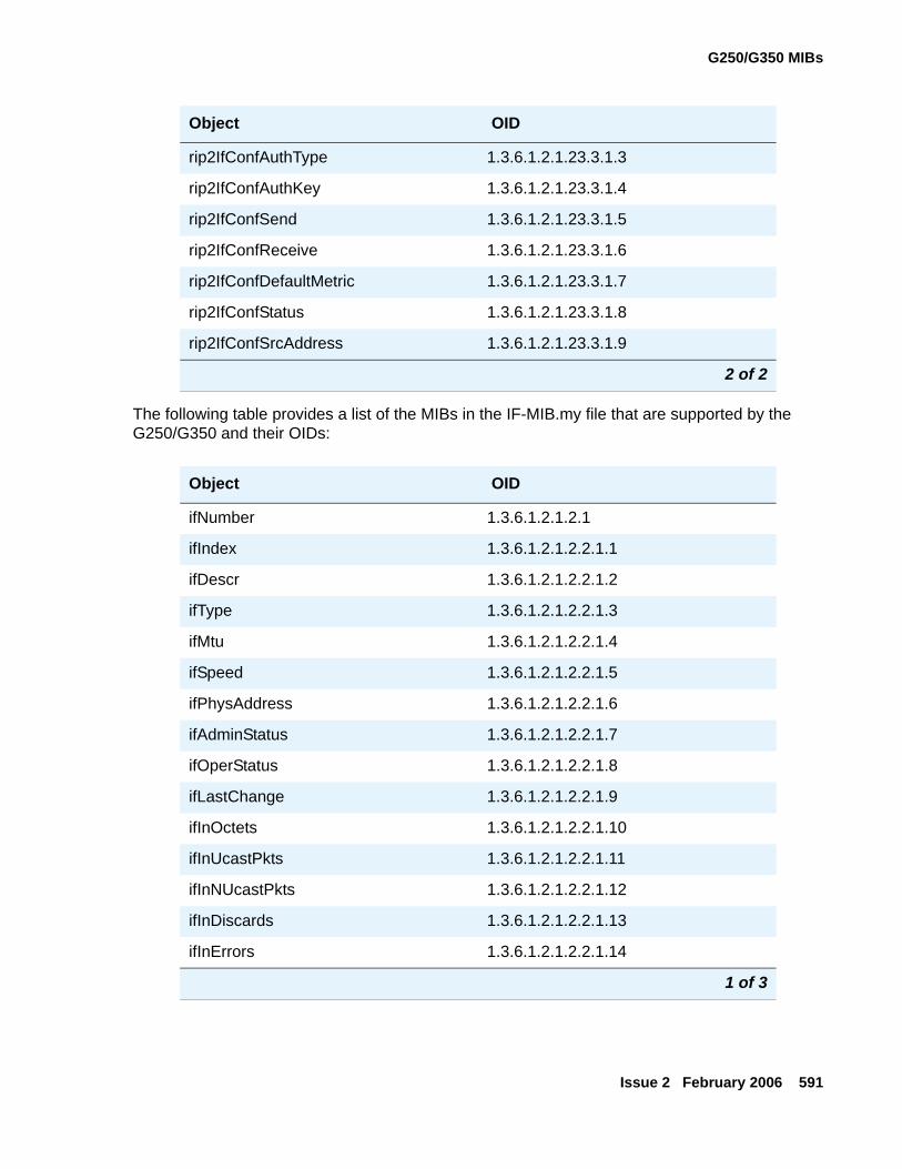
G250/G350 MIBs
Issue 2 February 2006 591
The following table provides a list of the MIBs in the IF-MIB.my file that are supported by the G250/G350 and their OIDs:
rip2IfConfAuthType 1.3.6.1.2.1.23.3.1.3
rip2IfConfAuthKey 1.3.6.1.2.1.23.3.1.4
rip2IfConfSend 1.3.6.1.2.1.23.3.1.5
rip2IfConfReceive 1.3.6.1.2.1.23.3.1.6
rip2IfConfDefaultMetric 1.3.6.1.2.1.23.3.1.7
rip2IfConfStatus 1.3.6.1.2.1.23.3.1.8
rip2IfConfSrcAddress 1.3.6.1.2.1.23.3.1.9
Object OID
ifNumber 1.3.6.1.2.1.2.1
ifIndex 1.3.6.1.2.1.2.2.1.1
ifDescr 1.3.6.1.2.1.2.2.1.2
ifType 1.3.6.1.2.1.2.2.1.3
ifMtu 1.3.6.1.2.1.2.2.1.4
ifSpeed 1.3.6.1.2.1.2.2.1.5
ifPhysAddress 1.3.6.1.2.1.2.2.1.6
ifAdminStatus 1.3.6.1.2.1.2.2.1.7
ifOperStatus 1.3.6.1.2.1.2.2.1.8
ifLastChange 1.3.6.1.2.1.2.2.1.9
ifInOctets 1.3.6.1.2.1.2.2.1.10
ifInUcastPkts 1.3.6.1.2.1.2.2.1.11
ifInNUcastPkts 1.3.6.1.2.1.2.2.1.12
ifInDiscards 1.3.6.1.2.1.2.2.1.13
ifInErrors 1.3.6.1.2.1.2.2.1.14
1 of 3
Object OID
2 of 2
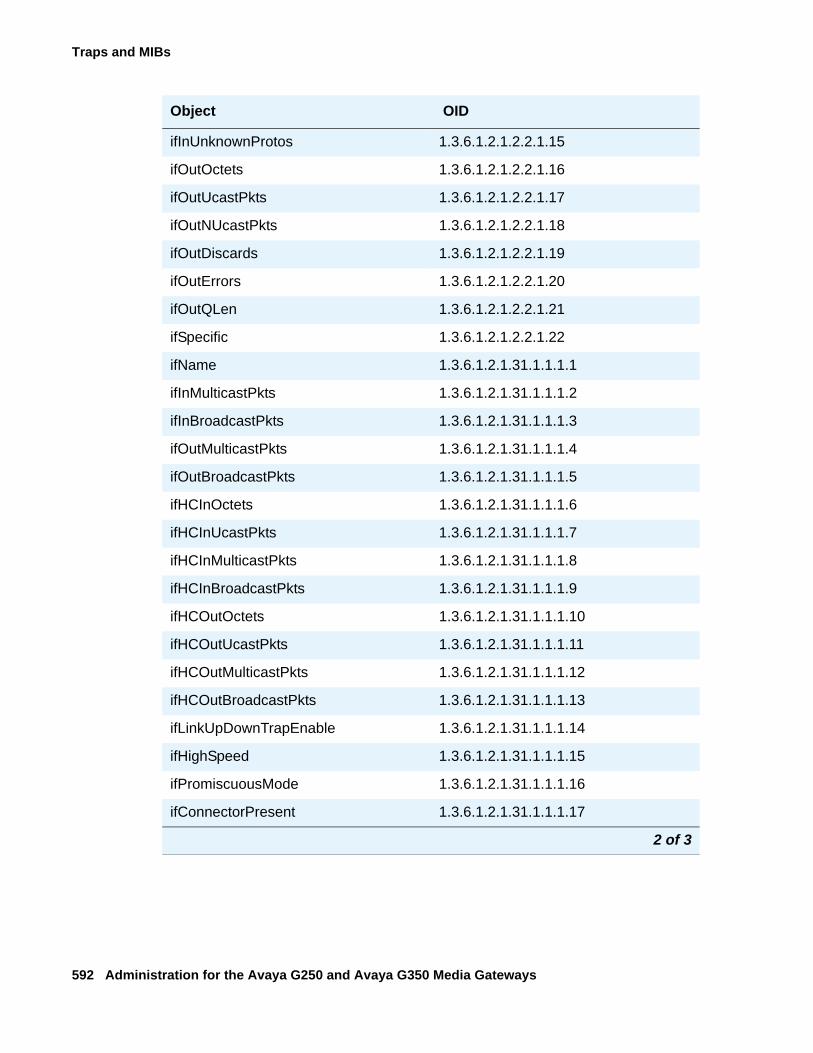
Traps and MIBs
592 Administration for the Avaya G250 and Avaya G350 Media Gateways
ifInUnknownProtos 1.3.6.1.2.1.2.2.1.15
ifOutOctets 1.3.6.1.2.1.2.2.1.16
ifOutUcastPkts 1.3.6.1.2.1.2.2.1.17
ifOutNUcastPkts 1.3.6.1.2.1.2.2.1.18
ifOutDiscards 1.3.6.1.2.1.2.2.1.19
ifOutErrors 1.3.6.1.2.1.2.2.1.20
ifOutQLen 1.3.6.1.2.1.2.2.1.21
ifSpecific 1.3.6.1.2.1.2.2.1.22
ifName 1.3.6.1.2.1.31.1.1.1.1
ifInMulticastPkts 1.3.6.1.2.1.31.1.1.1.2
ifInBroadcastPkts 1.3.6.1.2.1.31.1.1.1.3
ifOutMulticastPkts 1.3.6.1.2.1.31.1.1.1.4
ifOutBroadcastPkts 1.3.6.1.2.1.31.1.1.1.5
ifHCInOctets 1.3.6.1.2.1.31.1.1.1.6
ifHCInUcastPkts 1.3.6.1.2.1.31.1.1.1.7
ifHCInMulticastPkts 1.3.6.1.2.1.31.1.1.1.8
ifHCInBroadcastPkts 1.3.6.1.2.1.31.1.1.1.9
ifHCOutOctets 1.3.6.1.2.1.31.1.1.1.10
ifHCOutUcastPkts 1.3.6.1.2.1.31.1.1.1.11
ifHCOutMulticastPkts 1.3.6.1.2.1.31.1.1.1.12
ifHCOutBroadcastPkts 1.3.6.1.2.1.31.1.1.1.13
ifLinkUpDownTrapEnable 1.3.6.1.2.1.31.1.1.1.14
ifHighSpeed 1.3.6.1.2.1.31.1.1.1.15
ifPromiscuousMode 1.3.6.1.2.1.31.1.1.1.16
ifConnectorPresent 1.3.6.1.2.1.31.1.1.1.17
Object OID
2 of 3
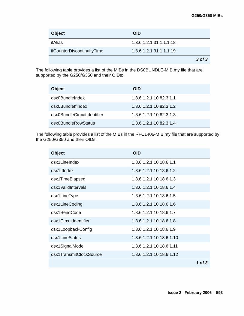
G250/G350 MIBs
Issue 2 February 2006 593
The following table provides a list of the MIBs in the DS0BUNDLE-MIB.my file that are supported by the G250/G350 and their OIDs:
The following table provides a list of the MIBs in the RFC1406-MIB.my file that are supported by the G250/G350 and their OIDs:
ifAlias 1.3.6.1.2.1.31.1.1.1.18
ifCounterDiscontinuityTime 1.3.6.1.2.1.31.1.1.1.19
Object OID
dsx0BundleIndex 1.3.6.1.2.1.10.82.3.1.1
dsx0BundleIfIndex 1.3.6.1.2.1.10.82.3.1.2
dsx0BundleCircuitIdentifier 1.3.6.1.2.1.10.82.3.1.3
dsx0BundleRowStatus 1.3.6.1.2.1.10.82.3.1.4
Object OID
dsx1LineIndex 1.3.6.1.2.1.10.18.6.1.1
dsx1IfIndex 1.3.6.1.2.1.10.18.6.1.2
dsx1TimeElapsed 1.3.6.1.2.1.10.18.6.1.3
dsx1ValidIntervals 1.3.6.1.2.1.10.18.6.1.4
dsx1LineType 1.3.6.1.2.1.10.18.6.1.5
dsx1LineCoding 1.3.6.1.2.1.10.18.6.1.6
dsx1SendCode 1.3.6.1.2.1.10.18.6.1.7
dsx1CircuitIdentifier 1.3.6.1.2.1.10.18.6.1.8
dsx1LoopbackConfig 1.3.6.1.2.1.10.18.6.1.9
dsx1LineStatus 1.3.6.1.2.1.10.18.6.1.10
dsx1SignalMode 1.3.6.1.2.1.10.18.6.1.11
dsx1TransmitClockSource 1.3.6.1.2.1.10.18.6.1.12
1 of 3
Object OID
3 of 3
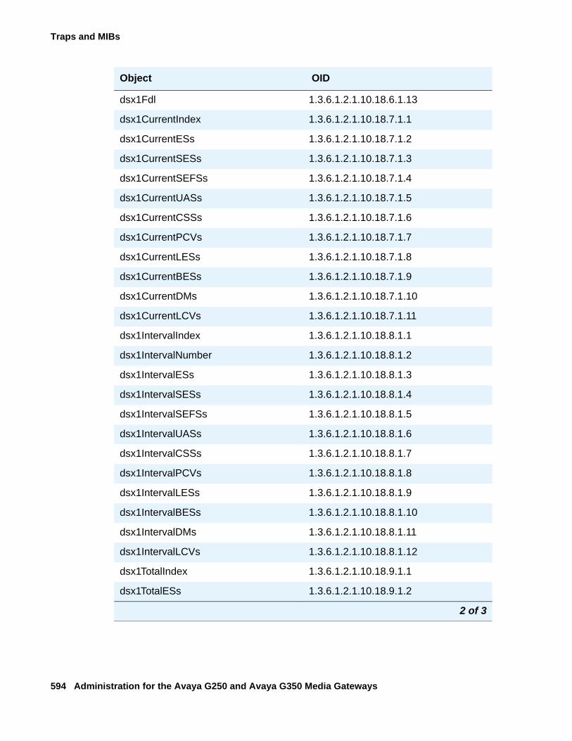
Traps and MIBs
594 Administration for the Avaya G250 and Avaya G350 Media Gateways
dsx1Fdl 1.3.6.1.2.1.10.18.6.1.13
dsx1CurrentIndex 1.3.6.1.2.1.10.18.7.1.1
dsx1CurrentESs 1.3.6.1.2.1.10.18.7.1.2
dsx1CurrentSESs 1.3.6.1.2.1.10.18.7.1.3
dsx1CurrentSEFSs 1.3.6.1.2.1.10.18.7.1.4
dsx1CurrentUASs 1.3.6.1.2.1.10.18.7.1.5
dsx1CurrentCSSs 1.3.6.1.2.1.10.18.7.1.6
dsx1CurrentPCVs 1.3.6.1.2.1.10.18.7.1.7
dsx1CurrentLESs 1.3.6.1.2.1.10.18.7.1.8
dsx1CurrentBESs 1.3.6.1.2.1.10.18.7.1.9
dsx1CurrentDMs 1.3.6.1.2.1.10.18.7.1.10
dsx1CurrentLCVs 1.3.6.1.2.1.10.18.7.1.11
dsx1IntervalIndex 1.3.6.1.2.1.10.18.8.1.1
dsx1IntervalNumber 1.3.6.1.2.1.10.18.8.1.2
dsx1IntervalESs 1.3.6.1.2.1.10.18.8.1.3
dsx1IntervalSESs 1.3.6.1.2.1.10.18.8.1.4
dsx1IntervalSEFSs 1.3.6.1.2.1.10.18.8.1.5
dsx1IntervalUASs 1.3.6.1.2.1.10.18.8.1.6
dsx1IntervalCSSs 1.3.6.1.2.1.10.18.8.1.7
dsx1IntervalPCVs 1.3.6.1.2.1.10.18.8.1.8
dsx1IntervalLESs 1.3.6.1.2.1.10.18.8.1.9
dsx1IntervalBESs 1.3.6.1.2.1.10.18.8.1.10
dsx1IntervalDMs 1.3.6.1.2.1.10.18.8.1.11
dsx1IntervalLCVs 1.3.6.1.2.1.10.18.8.1.12
dsx1TotalIndex 1.3.6.1.2.1.10.18.9.1.1
dsx1TotalESs 1.3.6.1.2.1.10.18.9.1.2
Object OID
2 of 3
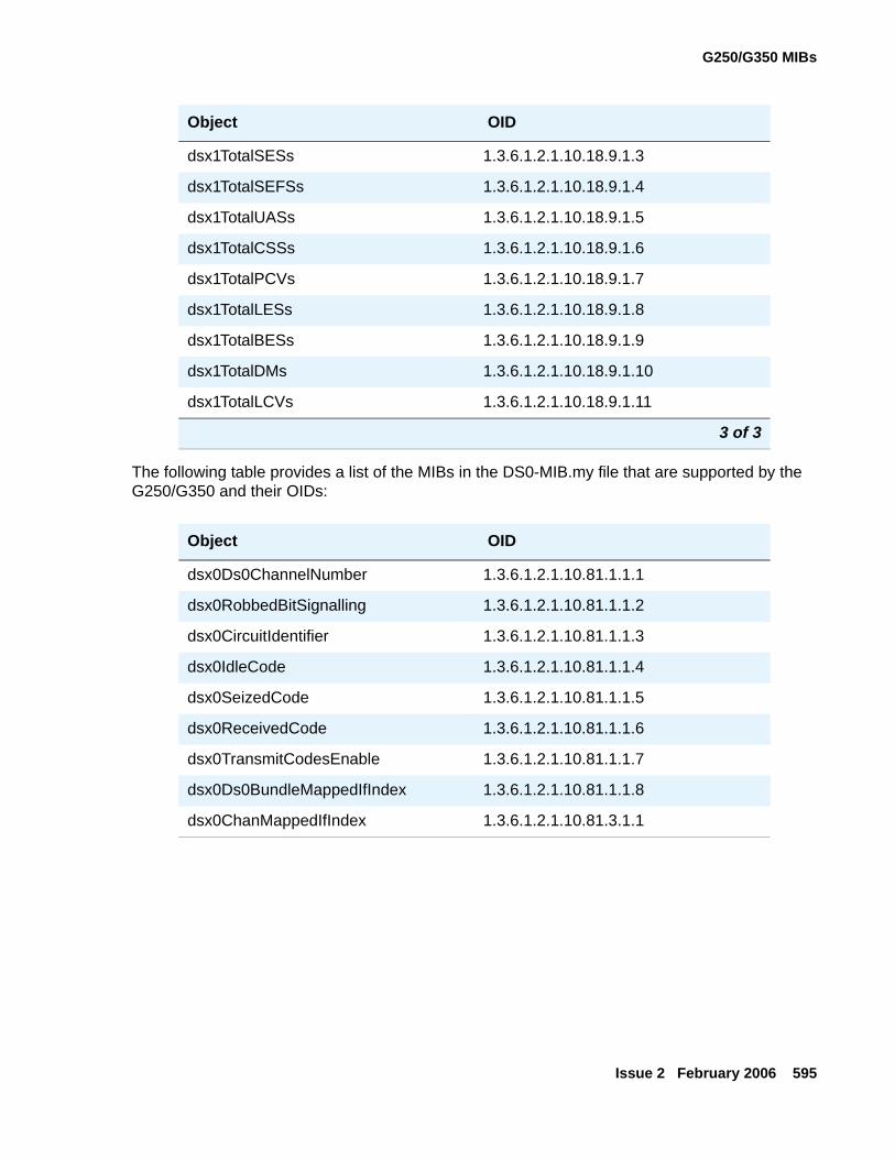
G250/G350 MIBs
Issue 2 February 2006 595
The following table provides a list of the MIBs in the DS0-MIB.my file that are supported by the G250/G350 and their OIDs:
dsx1TotalSESs 1.3.6.1.2.1.10.18.9.1.3
dsx1TotalSEFSs 1.3.6.1.2.1.10.18.9.1.4
dsx1TotalUASs 1.3.6.1.2.1.10.18.9.1.5
dsx1TotalCSSs 1.3.6.1.2.1.10.18.9.1.6
dsx1TotalPCVs 1.3.6.1.2.1.10.18.9.1.7
dsx1TotalLESs 1.3.6.1.2.1.10.18.9.1.8
dsx1TotalBESs 1.3.6.1.2.1.10.18.9.1.9
dsx1TotalDMs 1.3.6.1.2.1.10.18.9.1.10
dsx1TotalLCVs 1.3.6.1.2.1.10.18.9.1.11
Object OID
dsx0Ds0ChannelNumber 1.3.6.1.2.1.10.81.1.1.1
dsx0RobbedBitSignalling 1.3.6.1.2.1.10.81.1.1.2
dsx0CircuitIdentifier 1.3.6.1.2.1.10.81.1.1.3
dsx0IdleCode 1.3.6.1.2.1.10.81.1.1.4
dsx0SeizedCode 1.3.6.1.2.1.10.81.1.1.5
dsx0ReceivedCode 1.3.6.1.2.1.10.81.1.1.6
dsx0TransmitCodesEnable 1.3.6.1.2.1.10.81.1.1.7
dsx0Ds0BundleMappedIfIndex 1.3.6.1.2.1.10.81.1.1.8
dsx0ChanMappedIfIndex 1.3.6.1.2.1.10.81.3.1.1
Object OID
3 of 3
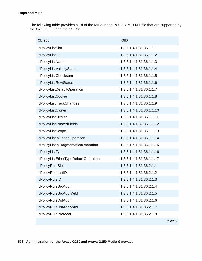
Traps and MIBs
596 Administration for the Avaya G250 and Avaya G350 Media Gateways
The following table provides a list of the MIBs in the POLICY-MIB.MY file that are supported by the G250/G350 and their OIDs:
Object OID
ipPolicyListSlot 1.3.6.1.4.1.81.36.1.1.1
ipPolicyListID 1.3.6.1.4.1.81.36.1.1.2
ipPolicyListName 1.3.6.1.4.1.81.36.1.1.3
ipPolicyListValidityStatus 1.3.6.1.4.1.81.36.1.1.4
ipPolicyListChecksum 1.3.6.1.4.1.81.36.1.1.5
ipPolicyListRowStatus 1.3.6.1.4.1.81.36.1.1.6
ipPolicyListDefaultOperation 1.3.6.1.4.1.81.36.1.1.7
ipPolicyListCookie 1.3.6.1.4.1.81.36.1.1.8
ipPolicyListTrackChanges 1.3.6.1.4.1.81.36.1.1.9
ipPolicyListOwner 1.3.6.1.4.1.81.36.1.1.10
ipPolicyListErrMsg 1.3.6.1.4.1.81.36.1.1.11
ipPolicyListTrustedFields 1.3.6.1.4.1.81.36.1.1.12
ipPolicyListScope 1.3.6.1.4.1.81.36.1.1.13
ipPolicyListIpOptionOperation 1.3.6.1.4.1.81.36.1.1.14
ipPolicyListIpFragmentationOperation 1.3.6.1.4.1.81.36.1.1.15
ipPolicyListType 1.3.6.1.4.1.81.36.1.1.16
ipPolicyListEtherTypeDefaultOperation 1.3.6.1.4.1.81.36.1.1.17
ipPolicyRuleSlot 1.3.6.1.4.1.81.36.2.1.1
ipPolicyRuleListID 1.3.6.1.4.1.81.36.2.1.2
ipPolicyRuleID 1.3.6.1.4.1.81.36.2.1.3
ipPolicyRuleSrcAddr 1.3.6.1.4.1.81.36.2.1.4
ipPolicyRuleSrcAddrWild 1.3.6.1.4.1.81.36.2.1.5
ipPolicyRuleDstAddr 1.3.6.1.4.1.81.36.2.1.6
ipPolicyRuleDstAddrWild 1.3.6.1.4.1.81.36.2.1.7
ipPolicyRuleProtocol 1.3.6.1.4.1.81.36.2.1.8
1 of 6
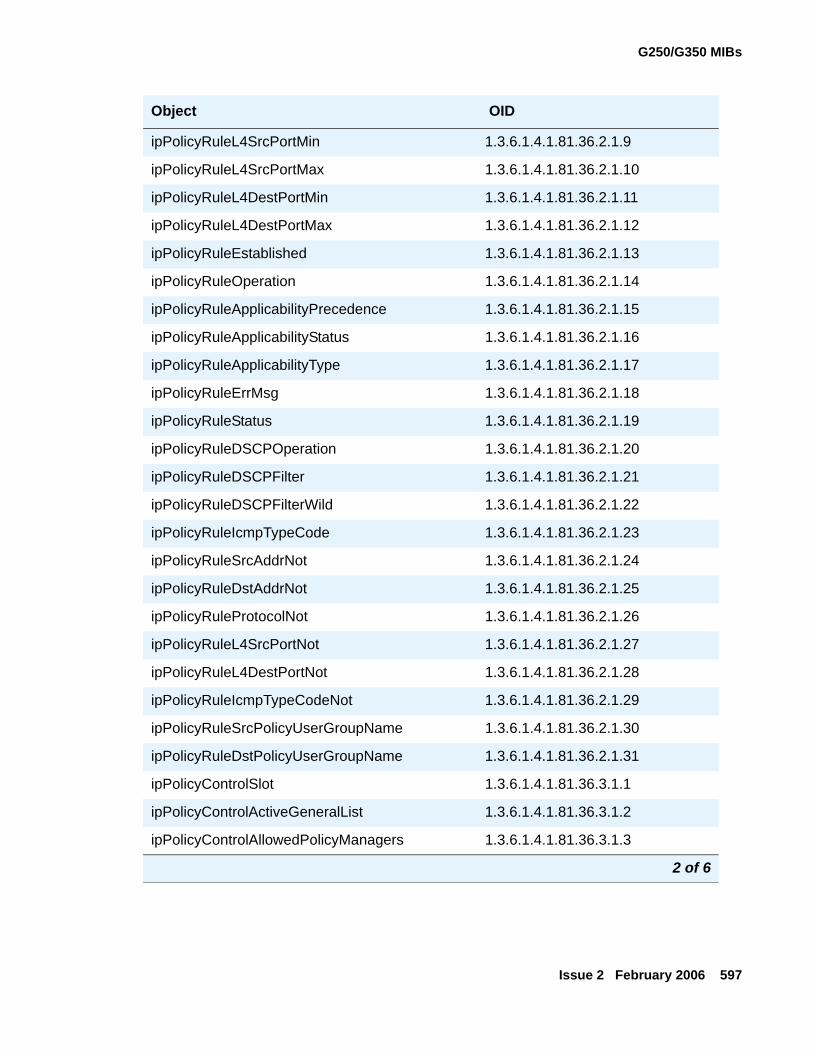
G250/G350 MIBs
Issue 2 February 2006 597
ipPolicyRuleL4SrcPortMin 1.3.6.1.4.1.81.36.2.1.9
ipPolicyRuleL4SrcPortMax 1.3.6.1.4.1.81.36.2.1.10
ipPolicyRuleL4DestPortMin 1.3.6.1.4.1.81.36.2.1.11
ipPolicyRuleL4DestPortMax 1.3.6.1.4.1.81.36.2.1.12
ipPolicyRuleEstablished 1.3.6.1.4.1.81.36.2.1.13
ipPolicyRuleOperation 1.3.6.1.4.1.81.36.2.1.14
ipPolicyRuleApplicabilityPrecedence 1.3.6.1.4.1.81.36.2.1.15
ipPolicyRuleApplicabilityStatus 1.3.6.1.4.1.81.36.2.1.16
ipPolicyRuleApplicabilityType 1.3.6.1.4.1.81.36.2.1.17
ipPolicyRuleErrMsg 1.3.6.1.4.1.81.36.2.1.18
ipPolicyRuleStatus 1.3.6.1.4.1.81.36.2.1.19
ipPolicyRuleDSCPOperation 1.3.6.1.4.1.81.36.2.1.20
ipPolicyRuleDSCPFilter 1.3.6.1.4.1.81.36.2.1.21
ipPolicyRuleDSCPFilterWild 1.3.6.1.4.1.81.36.2.1.22
ipPolicyRuleIcmpTypeCode 1.3.6.1.4.1.81.36.2.1.23
ipPolicyRuleSrcAddrNot 1.3.6.1.4.1.81.36.2.1.24
ipPolicyRuleDstAddrNot 1.3.6.1.4.1.81.36.2.1.25
ipPolicyRuleProtocolNot 1.3.6.1.4.1.81.36.2.1.26
ipPolicyRuleL4SrcPortNot 1.3.6.1.4.1.81.36.2.1.27
ipPolicyRuleL4DestPortNot 1.3.6.1.4.1.81.36.2.1.28
ipPolicyRuleIcmpTypeCodeNot 1.3.6.1.4.1.81.36.2.1.29
ipPolicyRuleSrcPolicyUserGroupName 1.3.6.1.4.1.81.36.2.1.30
ipPolicyRuleDstPolicyUserGroupName 1.3.6.1.4.1.81.36.2.1.31
ipPolicyControlSlot 1.3.6.1.4.1.81.36.3.1.1
ipPolicyControlActiveGeneralList 1.3.6.1.4.1.81.36.3.1.2
ipPolicyControlAllowedPolicyManagers 1.3.6.1.4.1.81.36.3.1.3
Object OID
2 of 6
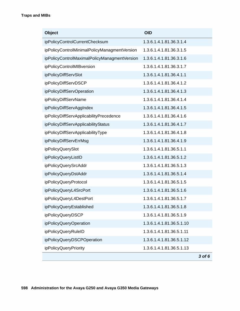
Traps and MIBs
598 Administration for the Avaya G250 and Avaya G350 Media Gateways
ipPolicyControlCurrentChecksum 1.3.6.1.4.1.81.36.3.1.4
ipPolicyControlMinimalPolicyManagmentVersion 1.3.6.1.4.1.81.36.3.1.5
ipPolicyControlMaximalPolicyManagmentVersion 1.3.6.1.4.1.81.36.3.1.6
ipPolicyControlMIBversion 1.3.6.1.4.1.81.36.3.1.7
ipPolicyDiffServSlot 1.3.6.1.4.1.81.36.4.1.1
ipPolicyDiffServDSCP 1.3.6.1.4.1.81.36.4.1.2
ipPolicyDiffServOperation 1.3.6.1.4.1.81.36.4.1.3
ipPolicyDiffServName 1.3.6.1.4.1.81.36.4.1.4
ipPolicyDiffServAggIndex 1.3.6.1.4.1.81.36.4.1.5
ipPolicyDiffServApplicabilityPrecedence 1.3.6.1.4.1.81.36.4.1.6
ipPolicyDiffServApplicabilityStatus 1.3.6.1.4.1.81.36.4.1.7
ipPolicyDiffServApplicabilityType 1.3.6.1.4.1.81.36.4.1.8
ipPolicyDiffServErrMsg 1.3.6.1.4.1.81.36.4.1.9
ipPolicyQuerySlot 1.3.6.1.4.1.81.36.5.1.1
ipPolicyQueryListID 1.3.6.1.4.1.81.36.5.1.2
ipPolicyQuerySrcAddr 1.3.6.1.4.1.81.36.5.1.3
ipPolicyQueryDstAddr 1.3.6.1.4.1.81.36.5.1.4
ipPolicyQueryProtocol 1.3.6.1.4.1.81.36.5.1.5
ipPolicyQueryL4SrcPort 1.3.6.1.4.1.81.36.5.1.6
ipPolicyQueryL4DestPort 1.3.6.1.4.1.81.36.5.1.7
ipPolicyQueryEstablished 1.3.6.1.4.1.81.36.5.1.8
ipPolicyQueryDSCP 1.3.6.1.4.1.81.36.5.1.9
ipPolicyQueryOperation 1.3.6.1.4.1.81.36.5.1.10
ipPolicyQueryRuleID 1.3.6.1.4.1.81.36.5.1.11
ipPolicyQueryDSCPOperation 1.3.6.1.4.1.81.36.5.1.12
ipPolicyQueryPriority 1.3.6.1.4.1.81.36.5.1.13
Object OID
3 of 6
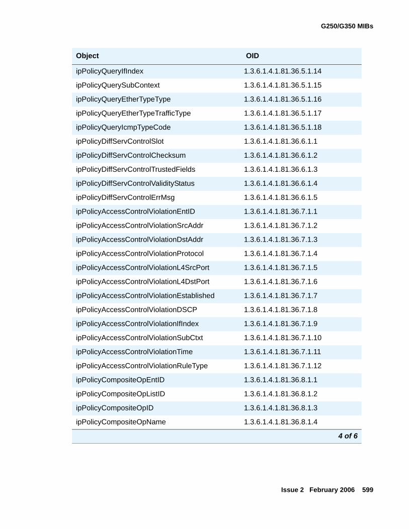
G250/G350 MIBs
Issue 2 February 2006 599
ipPolicyQueryIfIndex 1.3.6.1.4.1.81.36.5.1.14
ipPolicyQuerySubContext 1.3.6.1.4.1.81.36.5.1.15
ipPolicyQueryEtherTypeType 1.3.6.1.4.1.81.36.5.1.16
ipPolicyQueryEtherTypeTrafficType 1.3.6.1.4.1.81.36.5.1.17
ipPolicyQueryIcmpTypeCode 1.3.6.1.4.1.81.36.5.1.18
ipPolicyDiffServControlSlot 1.3.6.1.4.1.81.36.6.1.1
ipPolicyDiffServControlChecksum 1.3.6.1.4.1.81.36.6.1.2
ipPolicyDiffServControlTrustedFields 1.3.6.1.4.1.81.36.6.1.3
ipPolicyDiffServControlValidityStatus 1.3.6.1.4.1.81.36.6.1.4
ipPolicyDiffServControlErrMsg 1.3.6.1.4.1.81.36.6.1.5
ipPolicyAccessControlViolationEntID 1.3.6.1.4.1.81.36.7.1.1
ipPolicyAccessControlViolationSrcAddr 1.3.6.1.4.1.81.36.7.1.2
ipPolicyAccessControlViolationDstAddr 1.3.6.1.4.1.81.36.7.1.3
ipPolicyAccessControlViolationProtocol 1.3.6.1.4.1.81.36.7.1.4
ipPolicyAccessControlViolationL4SrcPort 1.3.6.1.4.1.81.36.7.1.5
ipPolicyAccessControlViolationL4DstPort 1.3.6.1.4.1.81.36.7.1.6
ipPolicyAccessControlViolationEstablished 1.3.6.1.4.1.81.36.7.1.7
ipPolicyAccessControlViolationDSCP 1.3.6.1.4.1.81.36.7.1.8
ipPolicyAccessControlViolationIfIndex 1.3.6.1.4.1.81.36.7.1.9
ipPolicyAccessControlViolationSubCtxt 1.3.6.1.4.1.81.36.7.1.10
ipPolicyAccessControlViolationTime 1.3.6.1.4.1.81.36.7.1.11
ipPolicyAccessControlViolationRuleType 1.3.6.1.4.1.81.36.7.1.12
ipPolicyCompositeOpEntID 1.3.6.1.4.1.81.36.8.1.1
ipPolicyCompositeOpListID 1.3.6.1.4.1.81.36.8.1.2
ipPolicyCompositeOpID 1.3.6.1.4.1.81.36.8.1.3
ipPolicyCompositeOpName 1.3.6.1.4.1.81.36.8.1.4
Object OID
4 of 6
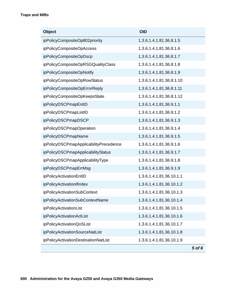
Traps and MIBs
600 Administration for the Avaya G250 and Avaya G350 Media Gateways
ipPolicyCompositeOp802priority 1.3.6.1.4.1.81.36.8.1.5
ipPolicyCompositeOpAccess 1.3.6.1.4.1.81.36.8.1.6
ipPolicyCompositeOpDscp 1.3.6.1.4.1.81.36.8.1.7
ipPolicyCompositeOpRSGQualityClass 1.3.6.1.4.1.81.36.8.1.8
ipPolicyCompositeOpNotify 1.3.6.1.4.1.81.36.8.1.9
ipPolicyCompositeOpRowStatus 1.3.6.1.4.1.81.36.8.1.10
ipPolicyCompositeOpErrorReply 1.3.6.1.4.1.81.36.8.1.11
ipPolicyCompositeOpKeepsState 1.3.6.1.4.1.81.36.8.1.12
ipPolicyDSCPmapEntID 1.3.6.1.4.1.81.36.9.1.1
ipPolicyDSCPmapListID 1.3.6.1.4.1.81.36.9.1.2
ipPolicyDSCPmapDSCP 1.3.6.1.4.1.81.36.9.1.3
ipPolicyDSCPmapOperation 1.3.6.1.4.1.81.36.9.1.4
ipPolicyDSCPmapName 1.3.6.1.4.1.81.36.9.1.5
ipPolicyDSCPmapApplicabilityPrecedence 1.3.6.1.4.1.81.36.9.1.6
ipPolicyDSCPmapApplicabilityStatus 1.3.6.1.4.1.81.36.9.1.7
ipPolicyDSCPmapApplicabilityType 1.3.6.1.4.1.81.36.9.1.8
ipPolicyDSCPmapErrMsg 1.3.6.1.4.1.81.36.9.1.9
ipPolicyActivationEntID 1.3.6.1.4.1.81.36.10.1.1
ipPolicyActivationifIndex 1.3.6.1.4.1.81.36.10.1.2
ipPolicyActivationSubContext 1.3.6.1.4.1.81.36.10.1.3
ipPolicyActivationSubContextName 1.3.6.1.4.1.81.36.10.1.4
ipPolicyActivationList 1.3.6.1.4.1.81.36.10.1.5
ipPolicyActivationAclList 1.3.6.1.4.1.81.36.10.1.6
ipPolicyActivationQoSList 1.3.6.1.4.1.81.36.10.1.7
ipPolicyActivationSourceNatList 1.3.6.1.4.1.81.36.10.1.8
ipPolicyActivationDestinationNatList 1.3.6.1.4.1.81.36.10.1.9
Object OID
5 of 6
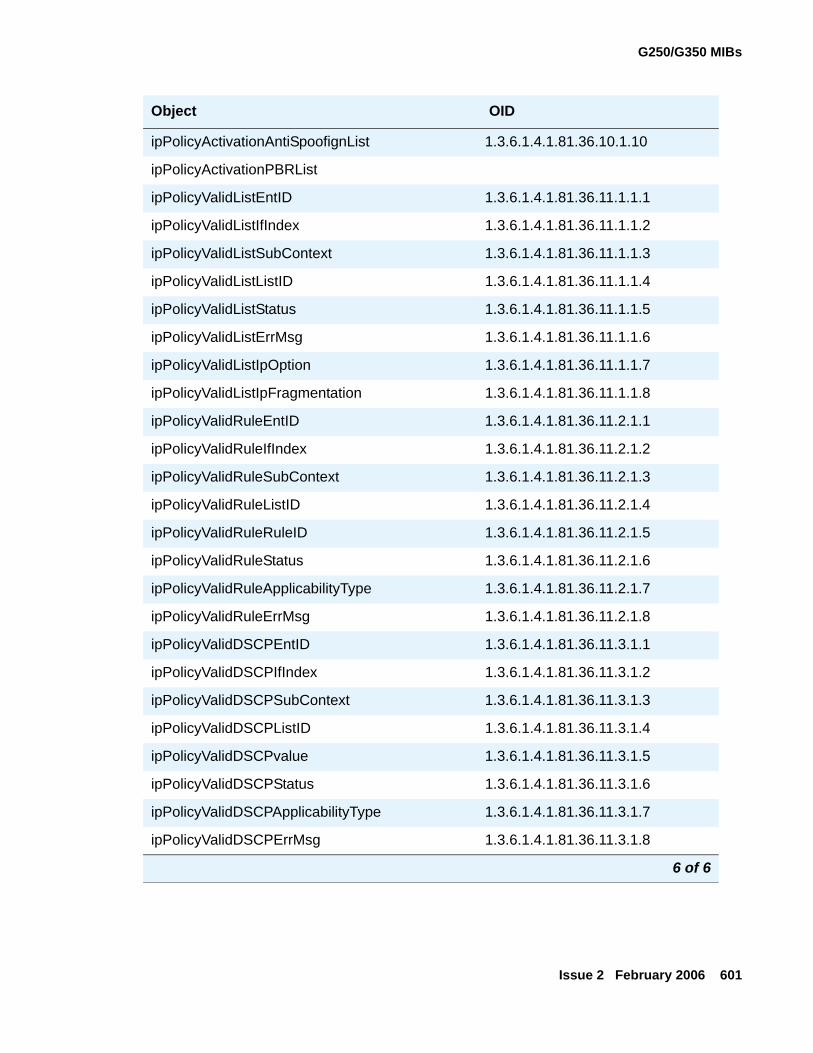
G250/G350 MIBs
Issue 2 February 2006 601
ipPolicyActivationAntiSpoofignList 1.3.6.1.4.1.81.36.10.1.10
ipPolicyActivationPBRList
ipPolicyValidListEntID 1.3.6.1.4.1.81.36.11.1.1.1
ipPolicyValidListIfIndex 1.3.6.1.4.1.81.36.11.1.1.2
ipPolicyValidListSubContext 1.3.6.1.4.1.81.36.11.1.1.3
ipPolicyValidListListID 1.3.6.1.4.1.81.36.11.1.1.4
ipPolicyValidListStatus 1.3.6.1.4.1.81.36.11.1.1.5
ipPolicyValidListErrMsg 1.3.6.1.4.1.81.36.11.1.1.6
ipPolicyValidListIpOption 1.3.6.1.4.1.81.36.11.1.1.7
ipPolicyValidListIpFragmentation 1.3.6.1.4.1.81.36.11.1.1.8
ipPolicyValidRuleEntID 1.3.6.1.4.1.81.36.11.2.1.1
ipPolicyValidRuleIfIndex 1.3.6.1.4.1.81.36.11.2.1.2
ipPolicyValidRuleSubContext 1.3.6.1.4.1.81.36.11.2.1.3
ipPolicyValidRuleListID 1.3.6.1.4.1.81.36.11.2.1.4
ipPolicyValidRuleRuleID 1.3.6.1.4.1.81.36.11.2.1.5
ipPolicyValidRuleStatus 1.3.6.1.4.1.81.36.11.2.1.6
ipPolicyValidRuleApplicabilityType 1.3.6.1.4.1.81.36.11.2.1.7
ipPolicyValidRuleErrMsg 1.3.6.1.4.1.81.36.11.2.1.8
ipPolicyValidDSCPEntID 1.3.6.1.4.1.81.36.11.3.1.1
ipPolicyValidDSCPIfIndex 1.3.6.1.4.1.81.36.11.3.1.2
ipPolicyValidDSCPSubContext 1.3.6.1.4.1.81.36.11.3.1.3
ipPolicyValidDSCPListID 1.3.6.1.4.1.81.36.11.3.1.4
ipPolicyValidDSCPvalue 1.3.6.1.4.1.81.36.11.3.1.5
ipPolicyValidDSCPStatus 1.3.6.1.4.1.81.36.11.3.1.6
ipPolicyValidDSCPApplicabilityType 1.3.6.1.4.1.81.36.11.3.1.7
ipPolicyValidDSCPErrMsg 1.3.6.1.4.1.81.36.11.3.1.8
Object OID
6 of 6
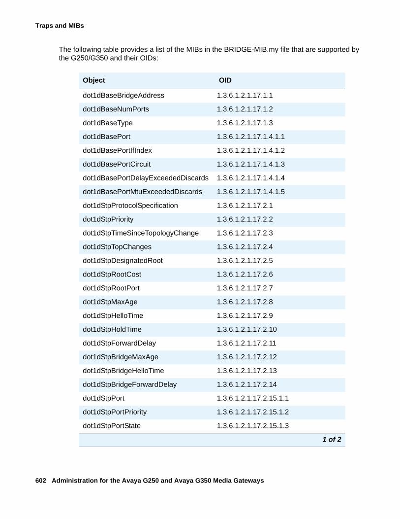
Traps and MIBs
602 Administration for the Avaya G250 and Avaya G350 Media Gateways
The following table provides a list of the MIBs in the BRIDGE-MIB.my file that are supported by the G250/G350 and their OIDs:
Object OID
dot1dBaseBridgeAddress 1.3.6.1.2.1.17.1.1
dot1dBaseNumPorts 1.3.6.1.2.1.17.1.2
dot1dBaseType 1.3.6.1.2.1.17.1.3
dot1dBasePort 1.3.6.1.2.1.17.1.4.1.1
dot1dBasePortIfIndex 1.3.6.1.2.1.17.1.4.1.2
dot1dBasePortCircuit 1.3.6.1.2.1.17.1.4.1.3
dot1dBasePortDelayExceededDiscards 1.3.6.1.2.1.17.1.4.1.4
dot1dBasePortMtuExceededDiscards 1.3.6.1.2.1.17.1.4.1.5
dot1dStpProtocolSpecification 1.3.6.1.2.1.17.2.1
dot1dStpPriority 1.3.6.1.2.1.17.2.2
dot1dStpTimeSinceTopologyChange 1.3.6.1.2.1.17.2.3
dot1dStpTopChanges 1.3.6.1.2.1.17.2.4
dot1dStpDesignatedRoot 1.3.6.1.2.1.17.2.5
dot1dStpRootCost 1.3.6.1.2.1.17.2.6
dot1dStpRootPort 1.3.6.1.2.1.17.2.7
dot1dStpMaxAge 1.3.6.1.2.1.17.2.8
dot1dStpHelloTime 1.3.6.1.2.1.17.2.9
dot1dStpHoldTime 1.3.6.1.2.1.17.2.10
dot1dStpForwardDelay 1.3.6.1.2.1.17.2.11
dot1dStpBridgeMaxAge 1.3.6.1.2.1.17.2.12
dot1dStpBridgeHelloTime 1.3.6.1.2.1.17.2.13
dot1dStpBridgeForwardDelay 1.3.6.1.2.1.17.2.14
dot1dStpPort 1.3.6.1.2.1.17.2.15.1.1
dot1dStpPortPriority 1.3.6.1.2.1.17.2.15.1.2
dot1dStpPortState 1.3.6.1.2.1.17.2.15.1.3
1 of 2
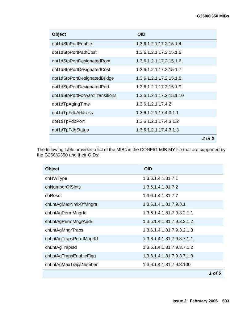
G250/G350 MIBs
Issue 2 February 2006 603
The following table provides a list of the MIBs in the CONFIG-MIB.MY file that are supported by the G250/G350 and their OIDs:
dot1dStpPortEnable 1.3.6.1.2.1.17.2.15.1.4
dot1dStpPortPathCost 1.3.6.1.2.1.17.2.15.1.5
dot1dStpPortDesignatedRoot 1.3.6.1.2.1.17.2.15.1.6
dot1dStpPortDesignatedCost 1.3.6.1.2.1.17.2.15.1.7
dot1dStpPortDesignatedBridge 1.3.6.1.2.1.17.2.15.1.8
dot1dStpPortDesignatedPort 1.3.6.1.2.1.17.2.15.1.9
dot1dStpPortForwardTransitions 1.3.6.1.2.1.17.2.15.1.10
dot1dTpAgingTime 1.3.6.1.2.1.17.4.2
dot1dTpFdbAddress 1.3.6.1.2.1.17.4.3.1.1
dot1dTpFdbPort 1.3.6.1.2.1.17.4.3.1.2
dot1dTpFdbStatus 1.3.6.1.2.1.17.4.3.1.3
Object OID
chHWType 1.3.6.1.4.1.81.7.1
chNumberOfSlots 1.3.6.1.4.1.81.7.2
chReset 1.3.6.1.4.1.81.7.7
chLntAgMaxNmbOfMngrs 1.3.6.1.4.1.81.7.9.3.1
chLntAgPermMngrId 1.3.6.1.4.1.81.7.9.3.2.1.1
chLntAgPermMngrAddr 1.3.6.1.4.1.81.7.9.3.2.1.2
chLntAgMngrTraps 1.3.6.1.4.1.81.7.9.3.2.1.3
chLntAgTrapsPermMngrId 1.3.6.1.4.1.81.7.9.3.7.1.1
chLntAgTrapsId 1.3.6.1.4.1.81.7.9.3.7.1.2
chLntAgTrapsEnableFlag 1.3.6.1.4.1.81.7.9.3.7.1.3
chLntAgMaxTrapsNumber 1.3.6.1.4.1.81.7.9.3.100
1 of 5
Object OID
2 of 2
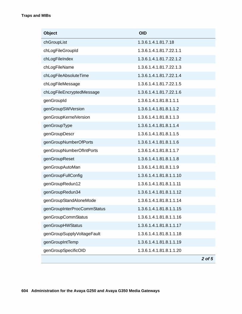
Traps and MIBs
604 Administration for the Avaya G250 and Avaya G350 Media Gateways
chGroupList 1.3.6.1.4.1.81.7.18
chLogFileGroupId 1.3.6.1.4.1.81.7.22.1.1
chLogFileIndex 1.3.6.1.4.1.81.7.22.1.2
chLogFileName 1.3.6.1.4.1.81.7.22.1.3
chLogFileAbsoluteTime 1.3.6.1.4.1.81.7.22.1.4
chLogFileMessage 1.3.6.1.4.1.81.7.22.1.5
chLogFileEncryptedMessage 1.3.6.1.4.1.81.7.22.1.6
genGroupId 1.3.6.1.4.1.81.8.1.1.1
genGroupSWVersion 1.3.6.1.4.1.81.8.1.1.2
genGroupKernelVersion 1.3.6.1.4.1.81.8.1.1.3
genGroupType 1.3.6.1.4.1.81.8.1.1.4
genGroupDescr 1.3.6.1.4.1.81.8.1.1.5
genGroupNumberOfPorts 1.3.6.1.4.1.81.8.1.1.6
genGroupNumberOfIntPorts 1.3.6.1.4.1.81.8.1.1.7
genGroupReset 1.3.6.1.4.1.81.8.1.1.8
genGroupAutoMan 1.3.6.1.4.1.81.8.1.1.9
genGroupFullConfig 1.3.6.1.4.1.81.8.1.1.10
genGroupRedun12 1.3.6.1.4.1.81.8.1.1.11
genGroupRedun34 1.3.6.1.4.1.81.8.1.1.12
genGroupStandAloneMode 1.3.6.1.4.1.81.8.1.1.14
genGroupInterProcCommStatus 1.3.6.1.4.1.81.8.1.1.15
genGroupCommStatus 1.3.6.1.4.1.81.8.1.1.16
genGroupHWStatus 1.3.6.1.4.1.81.8.1.1.17
genGroupSupplyVoltageFault 1.3.6.1.4.1.81.8.1.1.18
genGroupIntTemp 1.3.6.1.4.1.81.8.1.1.19
genGroupSpecificOID 1.3.6.1.4.1.81.8.1.1.20
Object OID
2 of 5
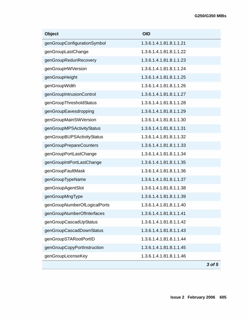
G250/G350 MIBs
Issue 2 February 2006 605
genGroupConfigurationSymbol 1.3.6.1.4.1.81.8.1.1.21
genGroupLastChange 1.3.6.1.4.1.81.8.1.1.22
genGroupRedunRecovery 1.3.6.1.4.1.81.8.1.1.23
genGroupHWVersion 1.3.6.1.4.1.81.8.1.1.24
genGroupHeight 1.3.6.1.4.1.81.8.1.1.25
genGroupWidth 1.3.6.1.4.1.81.8.1.1.26
genGroupIntrusionControl 1.3.6.1.4.1.81.8.1.1.27
genGroupThresholdStatus 1.3.6.1.4.1.81.8.1.1.28
genGroupEavesdropping 1.3.6.1.4.1.81.8.1.1.29
genGroupMainSWVersion 1.3.6.1.4.1.81.8.1.1.30
genGroupMPSActivityStatus 1.3.6.1.4.1.81.8.1.1.31
genGroupBUPSActivityStatus 1.3.6.1.4.1.81.8.1.1.32
genGroupPrepareCounters 1.3.6.1.4.1.81.8.1.1.33
genGroupPortLastChange 1.3.6.1.4.1.81.8.1.1.34
genGroupIntPortLastChange 1.3.6.1.4.1.81.8.1.1.35
genGroupFaultMask 1.3.6.1.4.1.81.8.1.1.36
genGroupTypeName 1.3.6.1.4.1.81.8.1.1.37
genGroupAgentSlot 1.3.6.1.4.1.81.8.1.1.38
genGroupMngType 1.3.6.1.4.1.81.8.1.1.39
genGroupNumberOfLogicalPorts 1.3.6.1.4.1.81.8.1.1.40
genGroupNumberOfInterfaces 1.3.6.1.4.1.81.8.1.1.41
genGroupCascadUpStatus 1.3.6.1.4.1.81.8.1.1.42
genGroupCascadDownStatus 1.3.6.1.4.1.81.8.1.1.43
genGroupSTARootPortID 1.3.6.1.4.1.81.8.1.1.44
genGroupCopyPortInstruction 1.3.6.1.4.1.81.8.1.1.45
genGroupLicenseKey 1.3.6.1.4.1.81.8.1.1.46
Object OID
3 of 5
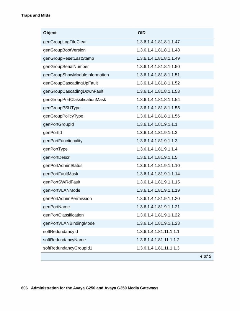
Traps and MIBs
606 Administration for the Avaya G250 and Avaya G350 Media Gateways
genGroupLogFileClear 1.3.6.1.4.1.81.8.1.1.47
genGroupBootVersion 1.3.6.1.4.1.81.8.1.1.48
genGroupResetLastStamp 1.3.6.1.4.1.81.8.1.1.49
genGroupSerialNumber 1.3.6.1.4.1.81.8.1.1.50
genGroupShowModuleInformation 1.3.6.1.4.1.81.8.1.1.51
genGroupCascadingUpFault 1.3.6.1.4.1.81.8.1.1.52
genGroupCascadingDownFault 1.3.6.1.4.1.81.8.1.1.53
genGroupPortClassificationMask 1.3.6.1.4.1.81.8.1.1.54
genGroupPSUType 1.3.6.1.4.1.81.8.1.1.55
genGroupPolicyType 1.3.6.1.4.1.81.8.1.1.56
genPortGroupId 1.3.6.1.4.1.81.9.1.1.1
genPortId 1.3.6.1.4.1.81.9.1.1.2
genPortFunctionality 1.3.6.1.4.1.81.9.1.1.3
genPortType 1.3.6.1.4.1.81.9.1.1.4
genPortDescr 1.3.6.1.4.1.81.9.1.1.5
genPortAdminStatus 1.3.6.1.4.1.81.9.1.1.10
genPortFaultMask 1.3.6.1.4.1.81.9.1.1.14
genPortSWRdFault 1.3.6.1.4.1.81.9.1.1.15
genPortVLANMode 1.3.6.1.4.1.81.9.1.1.19
genPortAdminPermission 1.3.6.1.4.1.81.9.1.1.20
genPortName 1.3.6.1.4.1.81.9.1.1.21
genPortClassification 1.3.6.1.4.1.81.9.1.1.22
genPortVLANBindingMode 1.3.6.1.4.1.81.9.1.1.23
softRedundancyId 1.3.6.1.4.1.81.11.1.1.1
softRedundancyName 1.3.6.1.4.1.81.11.1.1.2
softRedundancyGroupId1 1.3.6.1.4.1.81.11.1.1.3
Object OID
4 of 5
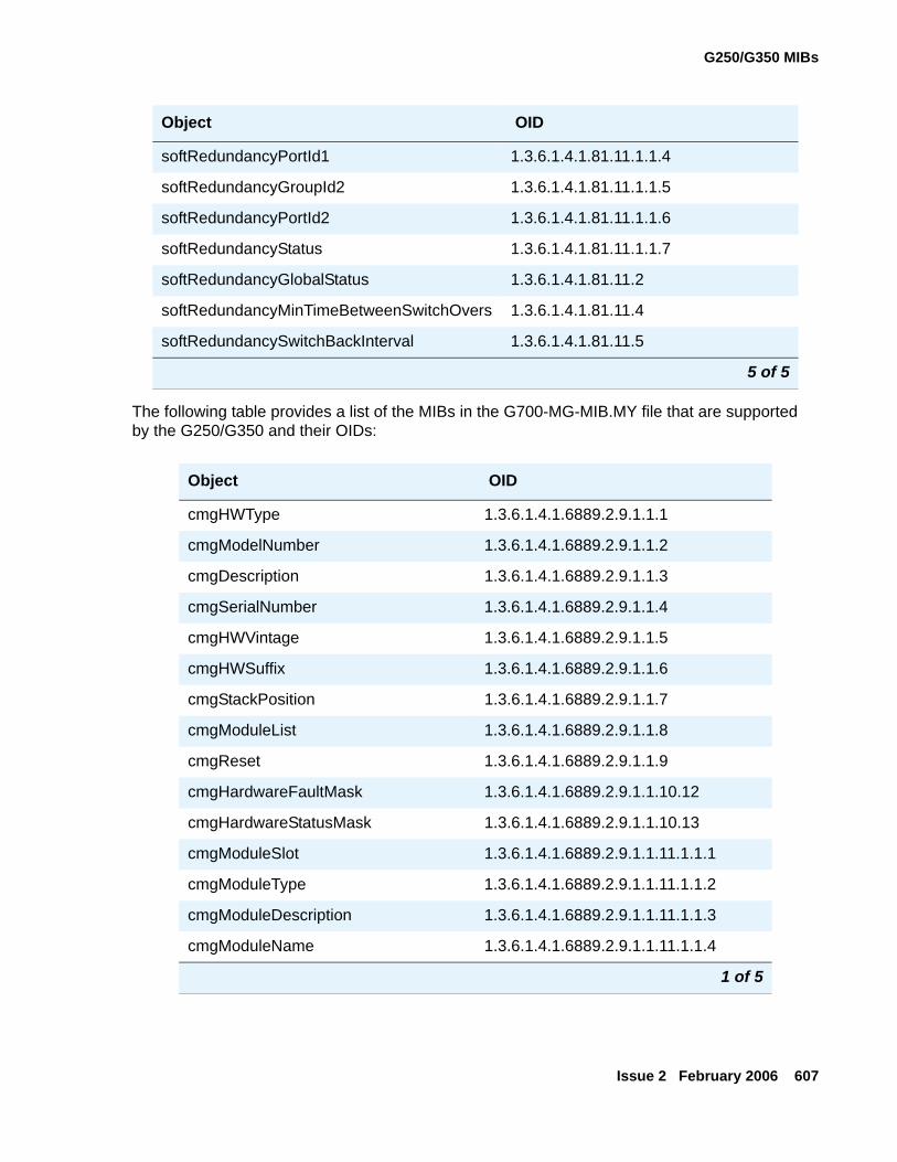
G250/G350 MIBs
Issue 2 February 2006 607
The following table provides a list of the MIBs in the G700-MG-MIB.MY file that are supported by the G250/G350 and their OIDs:
softRedundancyPortId1 1.3.6.1.4.1.81.11.1.1.4
softRedundancyGroupId2 1.3.6.1.4.1.81.11.1.1.5
softRedundancyPortId2 1.3.6.1.4.1.81.11.1.1.6
softRedundancyStatus 1.3.6.1.4.1.81.11.1.1.7
softRedundancyGlobalStatus 1.3.6.1.4.1.81.11.2
softRedundancyMinTimeBetweenSwitchOvers 1.3.6.1.4.1.81.11.4
softRedundancySwitchBackInterval 1.3.6.1.4.1.81.11.5
Object OID
cmgHWType 1.3.6.1.4.1.6889.2.9.1.1.1
cmgModelNumber 1.3.6.1.4.1.6889.2.9.1.1.2
cmgDescription 1.3.6.1.4.1.6889.2.9.1.1.3
cmgSerialNumber 1.3.6.1.4.1.6889.2.9.1.1.4
cmgHWVintage 1.3.6.1.4.1.6889.2.9.1.1.5
cmgHWSuffix 1.3.6.1.4.1.6889.2.9.1.1.6
cmgStackPosition 1.3.6.1.4.1.6889.2.9.1.1.7
cmgModuleList 1.3.6.1.4.1.6889.2.9.1.1.8
cmgReset 1.3.6.1.4.1.6889.2.9.1.1.9
cmgHardwareFaultMask 1.3.6.1.4.1.6889.2.9.1.1.10.12
cmgHardwareStatusMask 1.3.6.1.4.1.6889.2.9.1.1.10.13
cmgModuleSlot 1.3.6.1.4.1.6889.2.9.1.1.11.1.1.1
cmgModuleType 1.3.6.1.4.1.6889.2.9.1.1.11.1.1.2
cmgModuleDescription 1.3.6.1.4.1.6889.2.9.1.1.11.1.1.3
cmgModuleName 1.3.6.1.4.1.6889.2.9.1.1.11.1.1.4
1 of 5
Object OID
5 of 5
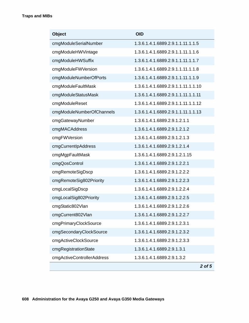
Traps and MIBs
608 Administration for the Avaya G250 and Avaya G350 Media Gateways
cmgModuleSerialNumber 1.3.6.1.4.1.6889.2.9.1.1.11.1.1.5
cmgModuleHWVintage 1.3.6.1.4.1.6889.2.9.1.1.11.1.1.6
cmgModuleHWSuffix 1.3.6.1.4.1.6889.2.9.1.1.11.1.1.7
cmgModuleFWVersion 1.3.6.1.4.1.6889.2.9.1.1.11.1.1.8
cmgModuleNumberOfPorts 1.3.6.1.4.1.6889.2.9.1.1.11.1.1.9
cmgModuleFaultMask 1.3.6.1.4.1.6889.2.9.1.1.11.1.1.10
cmgModuleStatusMask 1.3.6.1.4.1.6889.2.9.1.1.11.1.1.11
cmgModuleReset 1.3.6.1.4.1.6889.2.9.1.1.11.1.1.12
cmgModuleNumberOfChannels 1.3.6.1.4.1.6889.2.9.1.1.11.1.1.13
cmgGatewayNumber 1.3.6.1.4.1.6889.2.9.1.2.1.1
cmgMACAddress 1.3.6.1.4.1.6889.2.9.1.2.1.2
cmgFWVersion 1.3.6.1.4.1.6889.2.9.1.2.1.3
cmgCurrentIpAddress 1.3.6.1.4.1.6889.2.9.1.2.1.4
cmgMgpFaultMask 1.3.6.1.4.1.6889.2.9.1.2.1.15
cmgQosControl 1.3.6.1.4.1.6889.2.9.1.2.2.1
cmgRemoteSigDscp 1.3.6.1.4.1.6889.2.9.1.2.2.2
cmgRemoteSig802Priority 1.3.6.1.4.1.6889.2.9.1.2.2.3
cmgLocalSigDscp 1.3.6.1.4.1.6889.2.9.1.2.2.4
cmgLocalSig802Priority 1.3.6.1.4.1.6889.2.9.1.2.2.5
cmgStatic802Vlan 1.3.6.1.4.1.6889.2.9.1.2.2.6
cmgCurrent802Vlan 1.3.6.1.4.1.6889.2.9.1.2.2.7
cmgPrimaryClockSource 1.3.6.1.4.1.6889.2.9.1.2.3.1
cmgSecondaryClockSource 1.3.6.1.4.1.6889.2.9.1.2.3.2
cmgActiveClockSource 1.3.6.1.4.1.6889.2.9.1.2.3.3
cmgRegistrationState 1.3.6.1.4.1.6889.2.9.1.3.1
cmgActiveControllerAddress 1.3.6.1.4.1.6889.2.9.1.3.2
Object OID
2 of 5
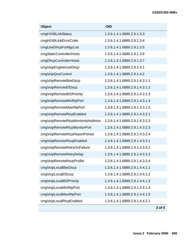
G250/G350 MIBs
Issue 2 February 2006 609
cmgH248LinkStatus 1.3.6.1.4.1.6889.2.9.1.3.3
cmgH248LinkErrorCode 1.3.6.1.4.1.6889.2.9.1.3.4
cmgUseDhcpForMgcList 1.3.6.1.4.1.6889.2.9.1.3.5
cmgStaticControllerHosts 1.3.6.1.4.1.6889.2.9.1.3.6
cmgDhcpControllerHosts 1.3.6.1.4.1.6889.2.9.1.3.7
cmgVoipEngineUseDhcp 1.3.6.1.4.1.6889.2.9.1.4.1
cmgVoipQosControl 1.3.6.1.4.1.6889.2.9.1.4.2
cmgVoipRemoteBbeDscp 1.3.6.1.4.1.6889.2.9.1.4.3.1.1
cmgVoipRemoteEfDscp 1.3.6.1.4.1.6889.2.9.1.4.3.1.2
cmgVoipRemote802Priority 1.3.6.1.4.1.6889.2.9.1.4.3.1.3
cmgVoipRemoteMinRtpPort 1.3.6.1.4.1.6889.2.9.1.4.3.1.4
cmgVoipRemoteMaxRtpPort 1.3.6.1.4.1.6889.2.9.1.4.3.1.5
cmgVoipRemoteRtcpEnabled 1.3.6.1.4.1.6889.2.9.1.4.3.2.1
cmgVoipRemoteRtcpMonitorIpAddress 1.3.6.1.4.1.6889.2.9.1.4.3.2.2
cmgVoipRemoteRtcpMonitorPort 1.3.6.1.4.1.6889.2.9.1.4.3.2.3
cmgVoipRemoteRtcpReportPeriod 1.3.6.1.4.1.6889.2.9.1.4.3.2.4
cmgVoipRemoteRsvpEnabled 1.3.6.1.4.1.6889.2.9.1.4.3.3.1
cmgVoipRemoteRetryOnFailure 1.3.6.1.4.1.6889.2.9.1.4.3.3.2
cmgVoipRemoteRetryDelay 1.3.6.1.4.1.6889.2.9.1.4.3.3.3
cmgVoipRemoteRsvpProfile 1.3.6.1.4.1.6889.2.9.1.4.3.3.4
cmgVoipLocalBbeDscp 1.3.6.1.4.1.6889.2.9.1.4.4.1.1
cmgVoipLocalEfDscp 1.3.6.1.4.1.6889.2.9.1.4.4.1.2
cmgVoipLocal802Priority 1.3.6.1.4.1.6889.2.9.1.4.4.1.3
cmgVoipLocalMinRtpPort 1.3.6.1.4.1.6889.2.9.1.4.4.1.4
cmgVoipLocalMaxRtpPort 1.3.6.1.4.1.6889.2.9.1.4.4.1.5
cmgVoipLocalRtcpEnabled 1.3.6.1.4.1.6889.2.9.1.4.4.2.1
Object OID
3 of 5
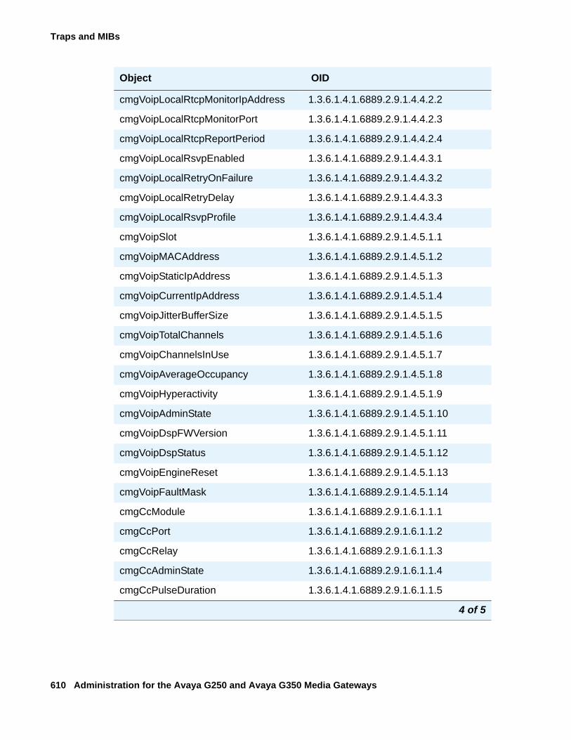
Traps and MIBs
610 Administration for the Avaya G250 and Avaya G350 Media Gateways
cmgVoipLocalRtcpMonitorIpAddress 1.3.6.1.4.1.6889.2.9.1.4.4.2.2
cmgVoipLocalRtcpMonitorPort 1.3.6.1.4.1.6889.2.9.1.4.4.2.3
cmgVoipLocalRtcpReportPeriod 1.3.6.1.4.1.6889.2.9.1.4.4.2.4
cmgVoipLocalRsvpEnabled 1.3.6.1.4.1.6889.2.9.1.4.4.3.1
cmgVoipLocalRetryOnFailure 1.3.6.1.4.1.6889.2.9.1.4.4.3.2
cmgVoipLocalRetryDelay 1.3.6.1.4.1.6889.2.9.1.4.4.3.3
cmgVoipLocalRsvpProfile 1.3.6.1.4.1.6889.2.9.1.4.4.3.4
cmgVoipSlot 1.3.6.1.4.1.6889.2.9.1.4.5.1.1
cmgVoipMACAddress 1.3.6.1.4.1.6889.2.9.1.4.5.1.2
cmgVoipStaticIpAddress 1.3.6.1.4.1.6889.2.9.1.4.5.1.3
cmgVoipCurrentIpAddress 1.3.6.1.4.1.6889.2.9.1.4.5.1.4
cmgVoipJitterBufferSize 1.3.6.1.4.1.6889.2.9.1.4.5.1.5
cmgVoipTotalChannels 1.3.6.1.4.1.6889.2.9.1.4.5.1.6
cmgVoipChannelsInUse 1.3.6.1.4.1.6889.2.9.1.4.5.1.7
cmgVoipAverageOccupancy 1.3.6.1.4.1.6889.2.9.1.4.5.1.8
cmgVoipHyperactivity 1.3.6.1.4.1.6889.2.9.1.4.5.1.9
cmgVoipAdminState 1.3.6.1.4.1.6889.2.9.1.4.5.1.10
cmgVoipDspFWVersion 1.3.6.1.4.1.6889.2.9.1.4.5.1.11
cmgVoipDspStatus 1.3.6.1.4.1.6889.2.9.1.4.5.1.12
cmgVoipEngineReset 1.3.6.1.4.1.6889.2.9.1.4.5.1.13
cmgVoipFaultMask 1.3.6.1.4.1.6889.2.9.1.4.5.1.14
cmgCcModule 1.3.6.1.4.1.6889.2.9.1.6.1.1.1
cmgCcPort 1.3.6.1.4.1.6889.2.9.1.6.1.1.2
cmgCcRelay 1.3.6.1.4.1.6889.2.9.1.6.1.1.3
cmgCcAdminState 1.3.6.1.4.1.6889.2.9.1.6.1.1.4
cmgCcPulseDuration 1.3.6.1.4.1.6889.2.9.1.6.1.1.5
Object OID
4 of 5
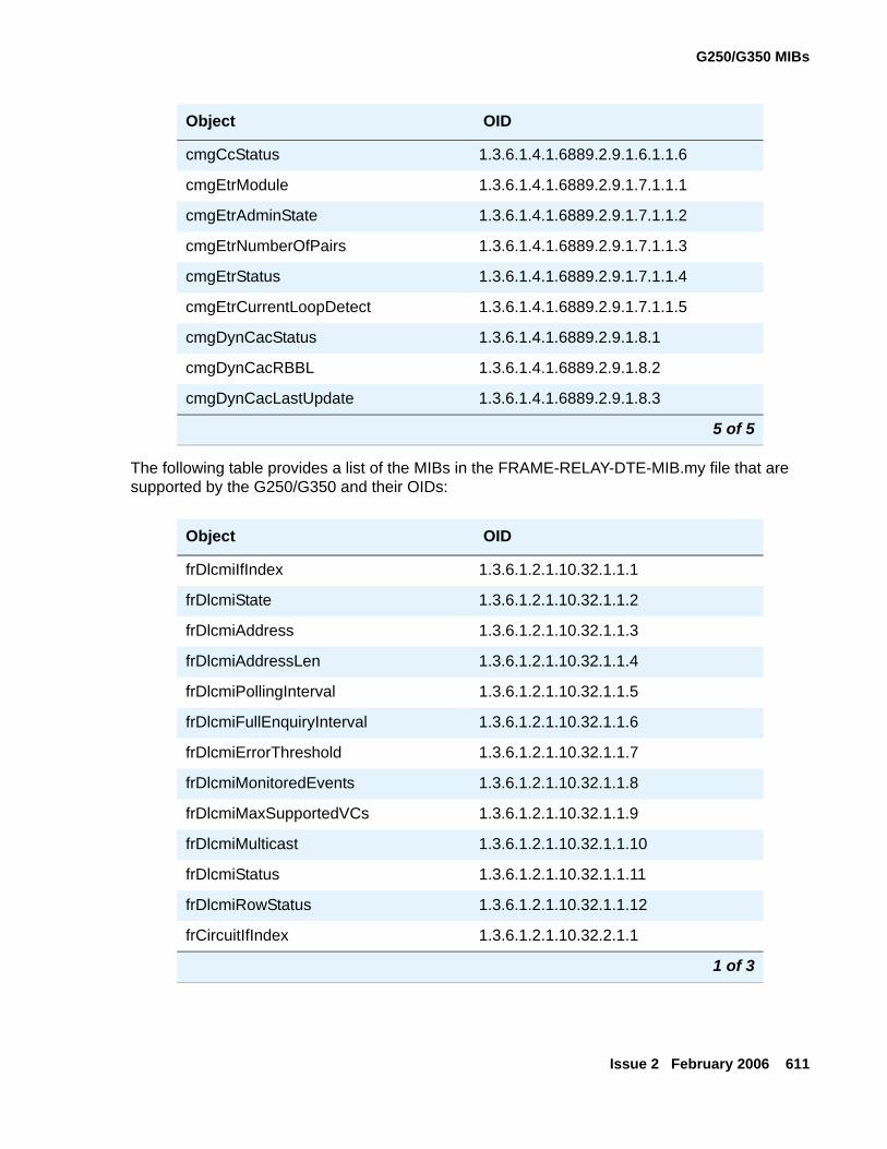
G250/G350 MIBs
Issue 2 February 2006 611
The following table provides a list of the MIBs in the FRAME-RELAY-DTE-MIB.my file that are supported by the G250/G350 and their OIDs:
cmgCcStatus 1.3.6.1.4.1.6889.2.9.1.6.1.1.6
cmgEtrModule 1.3.6.1.4.1.6889.2.9.1.7.1.1.1
cmgEtrAdminState 1.3.6.1.4.1.6889.2.9.1.7.1.1.2
cmgEtrNumberOfPairs 1.3.6.1.4.1.6889.2.9.1.7.1.1.3
cmgEtrStatus 1.3.6.1.4.1.6889.2.9.1.7.1.1.4
cmgEtrCurrentLoopDetect 1.3.6.1.4.1.6889.2.9.1.7.1.1.5
cmgDynCacStatus 1.3.6.1.4.1.6889.2.9.1.8.1
cmgDynCacRBBL 1.3.6.1.4.1.6889.2.9.1.8.2
cmgDynCacLastUpdate 1.3.6.1.4.1.6889.2.9.1.8.3
Object OID
frDlcmiIfIndex 1.3.6.1.2.1.10.32.1.1.1
frDlcmiState 1.3.6.1.2.1.10.32.1.1.2
frDlcmiAddress 1.3.6.1.2.1.10.32.1.1.3
frDlcmiAddressLen 1.3.6.1.2.1.10.32.1.1.4
frDlcmiPollingInterval 1.3.6.1.2.1.10.32.1.1.5
frDlcmiFullEnquiryInterval 1.3.6.1.2.1.10.32.1.1.6
frDlcmiErrorThreshold 1.3.6.1.2.1.10.32.1.1.7
frDlcmiMonitoredEvents 1.3.6.1.2.1.10.32.1.1.8
frDlcmiMaxSupportedVCs 1.3.6.1.2.1.10.32.1.1.9
frDlcmiMulticast 1.3.6.1.2.1.10.32.1.1.10
frDlcmiStatus 1.3.6.1.2.1.10.32.1.1.11
frDlcmiRowStatus 1.3.6.1.2.1.10.32.1.1.12
frCircuitIfIndex 1.3.6.1.2.1.10.32.2.1.1
1 of 3
Object OID
5 of 5
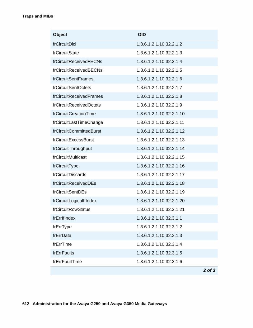
Traps and MIBs
612 Administration for the Avaya G250 and Avaya G350 Media Gateways
frCircuitDlci 1.3.6.1.2.1.10.32.2.1.2
frCircuitState 1.3.6.1.2.1.10.32.2.1.3
frCircuitReceivedFECNs 1.3.6.1.2.1.10.32.2.1.4
frCircuitReceivedBECNs 1.3.6.1.2.1.10.32.2.1.5
frCircuitSentFrames 1.3.6.1.2.1.10.32.2.1.6
frCircuitSentOctets 1.3.6.1.2.1.10.32.2.1.7
frCircuitReceivedFrames 1.3.6.1.2.1.10.32.2.1.8
frCircuitReceivedOctets 1.3.6.1.2.1.10.32.2.1.9
frCircuitCreationTime 1.3.6.1.2.1.10.32.2.1.10
frCircuitLastTimeChange 1.3.6.1.2.1.10.32.2.1.11
frCircuitCommittedBurst 1.3.6.1.2.1.10.32.2.1.12
frCircuitExcessBurst 1.3.6.1.2.1.10.32.2.1.13
frCircuitThroughput 1.3.6.1.2.1.10.32.2.1.14
frCircuitMulticast 1.3.6.1.2.1.10.32.2.1.15
frCircuitType 1.3.6.1.2.1.10.32.2.1.16
frCircuitDiscards 1.3.6.1.2.1.10.32.2.1.17
frCircuitReceivedDEs 1.3.6.1.2.1.10.32.2.1.18
frCircuitSentDEs 1.3.6.1.2.1.10.32.2.1.19
frCircuitLogicalIfIndex 1.3.6.1.2.1.10.32.2.1.20
frCircuitRowStatus 1.3.6.1.2.1.10.32.2.1.21
frErrIfIndex 1.3.6.1.2.1.10.32.3.1.1
frErrType 1.3.6.1.2.1.10.32.3.1.2
frErrData 1.3.6.1.2.1.10.32.3.1.3
frErrTime 1.3.6.1.2.1.10.32.3.1.4
frErrFaults 1.3.6.1.2.1.10.32.3.1.5
frErrFaultTime 1.3.6.1.2.1.10.32.3.1.6
Object OID
2 of 3
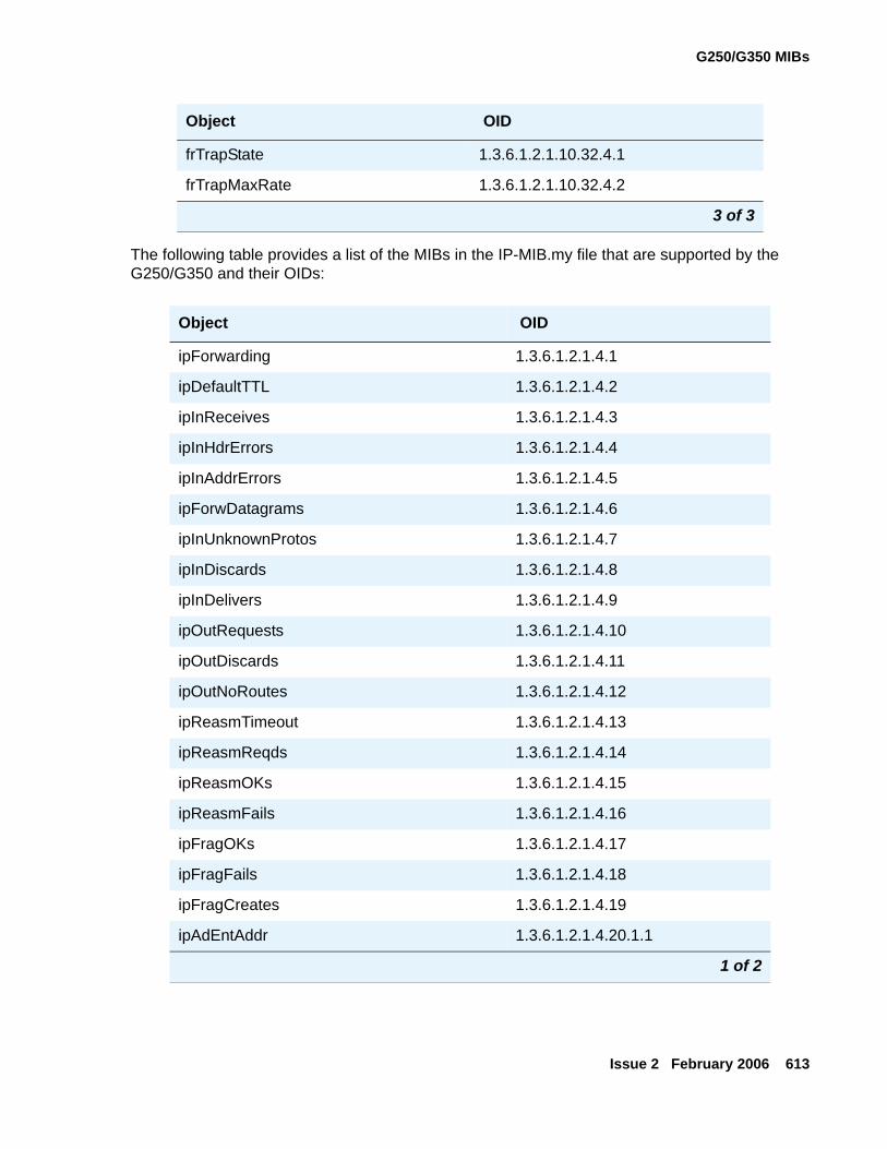
G250/G350 MIBs
Issue 2 February 2006 613
The following table provides a list of the MIBs in the IP-MIB.my file that are supported by the G250/G350 and their OIDs:
frTrapState 1.3.6.1.2.1.10.32.4.1
frTrapMaxRate 1.3.6.1.2.1.10.32.4.2
Object OID
ipForwarding 1.3.6.1.2.1.4.1
ipDefaultTTL 1.3.6.1.2.1.4.2
ipInReceives 1.3.6.1.2.1.4.3
ipInHdrErrors 1.3.6.1.2.1.4.4
ipInAddrErrors 1.3.6.1.2.1.4.5
ipForwDatagrams 1.3.6.1.2.1.4.6
ipInUnknownProtos 1.3.6.1.2.1.4.7
ipInDiscards 1.3.6.1.2.1.4.8
ipInDelivers 1.3.6.1.2.1.4.9
ipOutRequests 1.3.6.1.2.1.4.10
ipOutDiscards 1.3.6.1.2.1.4.11
ipOutNoRoutes 1.3.6.1.2.1.4.12
ipReasmTimeout 1.3.6.1.2.1.4.13
ipReasmReqds 1.3.6.1.2.1.4.14
ipReasmOKs 1.3.6.1.2.1.4.15
ipReasmFails 1.3.6.1.2.1.4.16
ipFragOKs 1.3.6.1.2.1.4.17
ipFragFails 1.3.6.1.2.1.4.18
ipFragCreates 1.3.6.1.2.1.4.19
ipAdEntAddr 1.3.6.1.2.1.4.20.1.1
1 of 2
Object OID
3 of 3
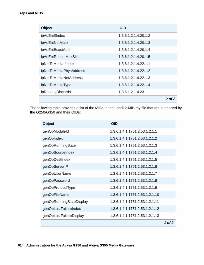
Traps and MIBs
614 Administration for the Avaya G250 and Avaya G350 Media Gateways
The following table provides a list of the MIBs in the Load12-MIB.my file that are supported by the G250/G350 and their OIDs:
ipAdEntIfIndex 1.3.6.1.2.1.4.20.1.2
ipAdEntNetMask 1.3.6.1.2.1.4.20.1.3
ipAdEntBcastAddr 1.3.6.1.2.1.4.20.1.4
ipAdEntReasmMaxSize 1.3.6.1.2.1.4.20.1.5
ipNetToMediaIfIndex 1.3.6.1.2.1.4.22.1.1
ipNetToMediaPhysAddress 1.3.6.1.2.1.4.22.1.2
ipNetToMediaNetAddress 1.3.6.1.2.1.4.22.1.3
ipNetToMediaType 1.3.6.1.2.1.4.22.1.4
ipRoutingDiscards 1.3.6.1.2.1.4.23
Object OID
genOpModuleId 1.3.6.1.4.1.1751.2.53.1.2.1.1
genOpIndex 1.3.6.1.4.1.1751.2.53.1.2.1.2
genOpRunningState 1.3.6.1.4.1.1751.2.53.1.2.1.3
genOpSourceIndex 1.3.6.1.4.1.1751.2.53.1.2.1.4
genOpDestIndex 1.3.6.1.4.1.1751.2.53.1.2.1.5
genOpServerIP 1.3.6.1.4.1.1751.2.53.1.2.1.6
genOpUserName 1.3.6.1.4.1.1751.2.53.1.2.1.7
genOpPassword 1.3.6.1.4.1.1751.2.53.1.2.1.8
genOpProtocolType 1.3.6.1.4.1.1751.2.53.1.2.1.9
genOpFileName 1.3.6.1.4.1.1751.2.53.1.2.1.10
genOpRunningStateDisplay 1.3.6.1.4.1.1751.2.53.1.2.1.11
genOpLastFailureIndex 1.3.6.1.4.1.1751.2.53.1.2.1.12
genOpLastFailureDisplay 1.3.6.1.4.1.1751.2.53.1.2.1.13
1 of 2
Object OID
2 of 2
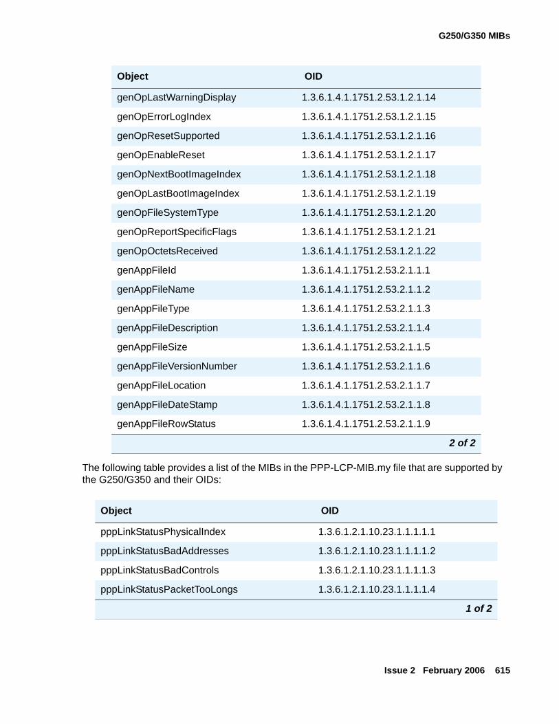
G250/G350 MIBs
Issue 2 February 2006 615
The following table provides a list of the MIBs in the PPP-LCP-MIB.my file that are supported by the G250/G350 and their OIDs:
genOpLastWarningDisplay 1.3.6.1.4.1.1751.2.53.1.2.1.14
genOpErrorLogIndex 1.3.6.1.4.1.1751.2.53.1.2.1.15
genOpResetSupported 1.3.6.1.4.1.1751.2.53.1.2.1.16
genOpEnableReset 1.3.6.1.4.1.1751.2.53.1.2.1.17
genOpNextBootImageIndex 1.3.6.1.4.1.1751.2.53.1.2.1.18
genOpLastBootImageIndex 1.3.6.1.4.1.1751.2.53.1.2.1.19
genOpFileSystemType 1.3.6.1.4.1.1751.2.53.1.2.1.20
genOpReportSpecificFlags 1.3.6.1.4.1.1751.2.53.1.2.1.21
genOpOctetsReceived 1.3.6.1.4.1.1751.2.53.1.2.1.22
genAppFileId 1.3.6.1.4.1.1751.2.53.2.1.1.1
genAppFileName 1.3.6.1.4.1.1751.2.53.2.1.1.2
genAppFileType 1.3.6.1.4.1.1751.2.53.2.1.1.3
genAppFileDescription 1.3.6.1.4.1.1751.2.53.2.1.1.4
genAppFileSize 1.3.6.1.4.1.1751.2.53.2.1.1.5
genAppFileVersionNumber 1.3.6.1.4.1.1751.2.53.2.1.1.6
genAppFileLocation 1.3.6.1.4.1.1751.2.53.2.1.1.7
genAppFileDateStamp 1.3.6.1.4.1.1751.2.53.2.1.1.8
genAppFileRowStatus 1.3.6.1.4.1.1751.2.53.2.1.1.9
Object OID
pppLinkStatusPhysicalIndex 1.3.6.1.2.1.10.23.1.1.1.1.1
pppLinkStatusBadAddresses 1.3.6.1.2.1.10.23.1.1.1.1.2
pppLinkStatusBadControls 1.3.6.1.2.1.10.23.1.1.1.1.3
pppLinkStatusPacketTooLongs 1.3.6.1.2.1.10.23.1.1.1.1.4
1 of 2
Object OID
2 of 2
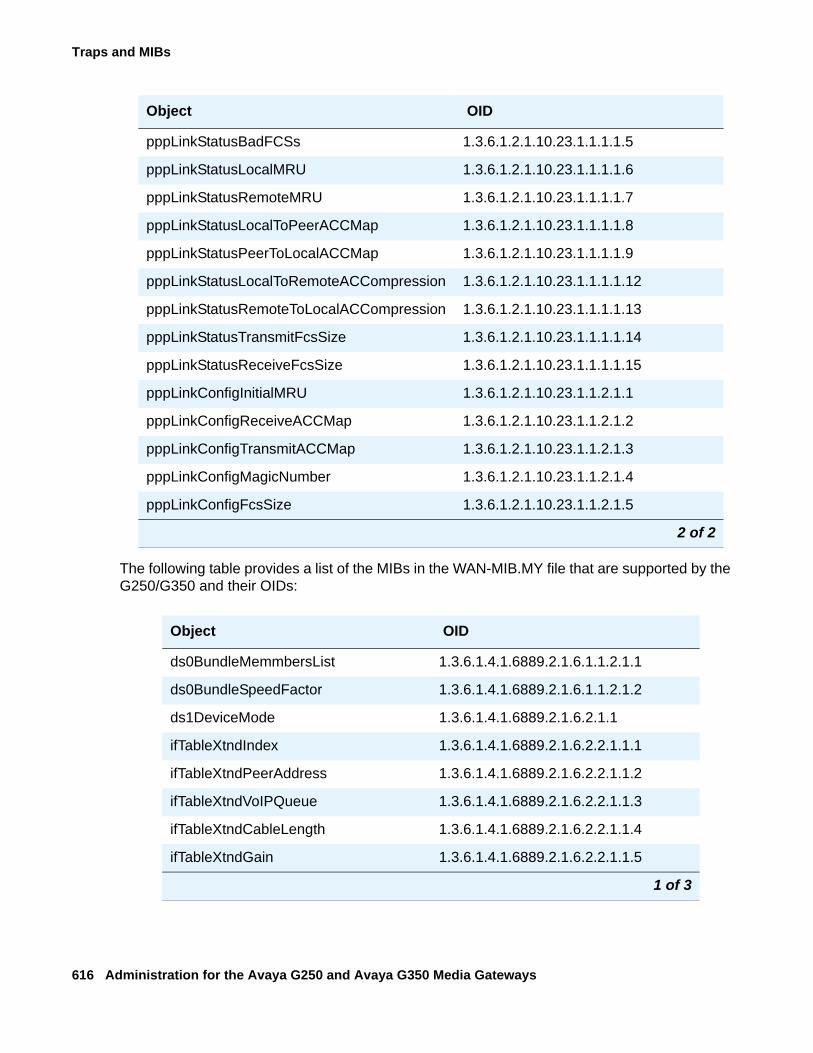
Traps and MIBs
616 Administration for the Avaya G250 and Avaya G350 Media Gateways
The following table provides a list of the MIBs in the WAN-MIB.MY file that are supported by the G250/G350 and their OIDs:
pppLinkStatusBadFCSs 1.3.6.1.2.1.10.23.1.1.1.1.5
pppLinkStatusLocalMRU 1.3.6.1.2.1.10.23.1.1.1.1.6
pppLinkStatusRemoteMRU 1.3.6.1.2.1.10.23.1.1.1.1.7
pppLinkStatusLocalToPeerACCMap 1.3.6.1.2.1.10.23.1.1.1.1.8
pppLinkStatusPeerToLocalACCMap 1.3.6.1.2.1.10.23.1.1.1.1.9
pppLinkStatusLocalToRemoteACCompression 1.3.6.1.2.1.10.23.1.1.1.1.12
pppLinkStatusRemoteToLocalACCompression 1.3.6.1.2.1.10.23.1.1.1.1.13
pppLinkStatusTransmitFcsSize 1.3.6.1.2.1.10.23.1.1.1.1.14
pppLinkStatusReceiveFcsSize 1.3.6.1.2.1.10.23.1.1.1.1.15
pppLinkConfigInitialMRU 1.3.6.1.2.1.10.23.1.1.2.1.1
pppLinkConfigReceiveACCMap 1.3.6.1.2.1.10.23.1.1.2.1.2
pppLinkConfigTransmitACCMap 1.3.6.1.2.1.10.23.1.1.2.1.3
pppLinkConfigMagicNumber 1.3.6.1.2.1.10.23.1.1.2.1.4
pppLinkConfigFcsSize 1.3.6.1.2.1.10.23.1.1.2.1.5
Object OID
ds0BundleMemmbersList 1.3.6.1.4.1.6889.2.1.6.1.1.2.1.1
ds0BundleSpeedFactor 1.3.6.1.4.1.6889.2.1.6.1.1.2.1.2
ds1DeviceMode 1.3.6.1.4.1.6889.2.1.6.2.1.1
ifTableXtndIndex 1.3.6.1.4.1.6889.2.1.6.2.2.1.1.1
ifTableXtndPeerAddress 1.3.6.1.4.1.6889.2.1.6.2.2.1.1.2
ifTableXtndVoIPQueue 1.3.6.1.4.1.6889.2.1.6.2.2.1.1.3
ifTableXtndCableLength 1.3.6.1.4.1.6889.2.1.6.2.2.1.1.4
ifTableXtndGain 1.3.6.1.4.1.6889.2.1.6.2.2.1.1.5
1 of 3
Object OID
2 of 2
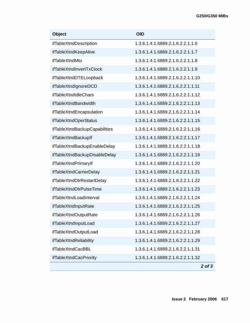
G250/G350 MIBs
Issue 2 February 2006 617
ifTableXtndDescription 1.3.6.1.4.1.6889.2.1.6.2.2.1.1.6
ifTableXtndKeepAlive 1.3.6.1.4.1.6889.2.1.6.2.2.1.1.7
ifTableXtndMtu 1.3.6.1.4.1.6889.2.1.6.2.2.1.1.8
ifTableXtndInvertTxClock 1.3.6.1.4.1.6889.2.1.6.2.2.1.1.9
ifTableXtndDTELoopback 1.3.6.1.4.1.6889.2.1.6.2.2.1.1.10
ifTableXtndIgnoreDCD 1.3.6.1.4.1.6889.2.1.6.2.2.1.1.11
ifTableXtndIdleChars 1.3.6.1.4.1.6889.2.1.6.2.2.1.1.12
ifTableXtndBandwidth 1.3.6.1.4.1.6889.2.1.6.2.2.1.1.13
ifTableXtndEncapsulation 1.3.6.1.4.1.6889.2.1.6.2.2.1.1.14
ifTableXtndOperStatus 1.3.6.1.4.1.6889.2.1.6.2.2.1.1.15
ifTableXtndBackupCapabilities 1.3.6.1.4.1.6889.2.1.6.2.2.1.1.16
ifTableXtndBackupIf 1.3.6.1.4.1.6889.2.1.6.2.2.1.1.17
ifTableXtndBackupEnableDelay 1.3.6.1.4.1.6889.2.1.6.2.2.1.1.18
ifTableXtndBackupDisableDelay 1.3.6.1.4.1.6889.2.1.6.2.2.1.1.19
ifTableXtndPrimaryIf 1.3.6.1.4.1.6889.2.1.6.2.2.1.1.20
ifTableXtndCarrierDelay 1.3.6.1.4.1.6889.2.1.6.2.2.1.1.21
ifTableXtndDtrRestartDelay 1.3.6.1.4.1.6889.2.1.6.2.2.1.1.22
ifTableXtndDtrPulseTime 1.3.6.1.4.1.6889.2.1.6.2.2.1.1.23
ifTableXtndLoadInterval 1.3.6.1.4.1.6889.2.1.6.2.2.1.1.24
ifTableXtndInputRate 1.3.6.1.4.1.6889.2.1.6.2.2.1.1.25
ifTableXtndOutputRate 1.3.6.1.4.1.6889.2.1.6.2.2.1.1.26
ifTableXtndInputLoad 1.3.6.1.4.1.6889.2.1.6.2.2.1.1.27
ifTableXtndOutputLoad 1.3.6.1.4.1.6889.2.1.6.2.2.1.1.28
ifTableXtndReliability 1.3.6.1.4.1.6889.2.1.6.2.2.1.1.29
ifTableXtndCacBBL 1.3.6.1.4.1.6889.2.1.6.2.2.1.1.31
ifTableXtndCacPriority 1.3.6.1.4.1.6889.2.1.6.2.2.1.1.32
Object OID
2 of 3
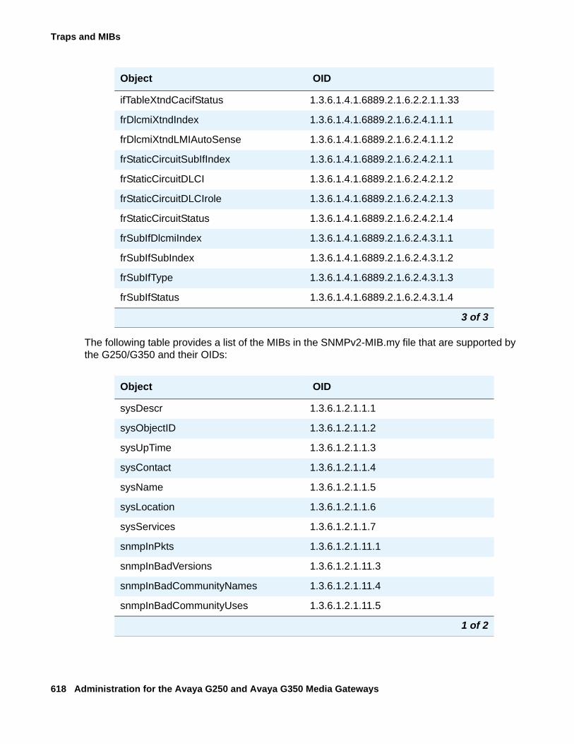
Traps and MIBs
618 Administration for the Avaya G250 and Avaya G350 Media Gateways
The following table provides a list of the MIBs in the SNMPv2-MIB.my file that are supported by the G250/G350 and their OIDs:
ifTableXtndCacifStatus 1.3.6.1.4.1.6889.2.1.6.2.2.1.1.33
frDlcmiXtndIndex 1.3.6.1.4.1.6889.2.1.6.2.4.1.1.1
frDlcmiXtndLMIAutoSense 1.3.6.1.4.1.6889.2.1.6.2.4.1.1.2
frStaticCircuitSubIfIndex 1.3.6.1.4.1.6889.2.1.6.2.4.2.1.1
frStaticCircuitDLCI 1.3.6.1.4.1.6889.2.1.6.2.4.2.1.2
frStaticCircuitDLCIrole 1.3.6.1.4.1.6889.2.1.6.2.4.2.1.3
frStaticCircuitStatus 1.3.6.1.4.1.6889.2.1.6.2.4.2.1.4
frSubIfDlcmiIndex 1.3.6.1.4.1.6889.2.1.6.2.4.3.1.1
frSubIfSubIndex 1.3.6.1.4.1.6889.2.1.6.2.4.3.1.2
frSubIfType 1.3.6.1.4.1.6889.2.1.6.2.4.3.1.3
frSubIfStatus 1.3.6.1.4.1.6889.2.1.6.2.4.3.1.4
Object OID
sysDescr 1.3.6.1.2.1.1.1
sysObjectID 1.3.6.1.2.1.1.2
sysUpTime 1.3.6.1.2.1.1.3
sysContact 1.3.6.1.2.1.1.4
sysName 1.3.6.1.2.1.1.5
sysLocation 1.3.6.1.2.1.1.6
sysServices 1.3.6.1.2.1.1.7
snmpInPkts 1.3.6.1.2.1.11.1
snmpInBadVersions 1.3.6.1.2.1.11.3
snmpInBadCommunityNames 1.3.6.1.2.1.11.4
snmpInBadCommunityUses 1.3.6.1.2.1.11.5
1 of 2
Object OID
3 of 3
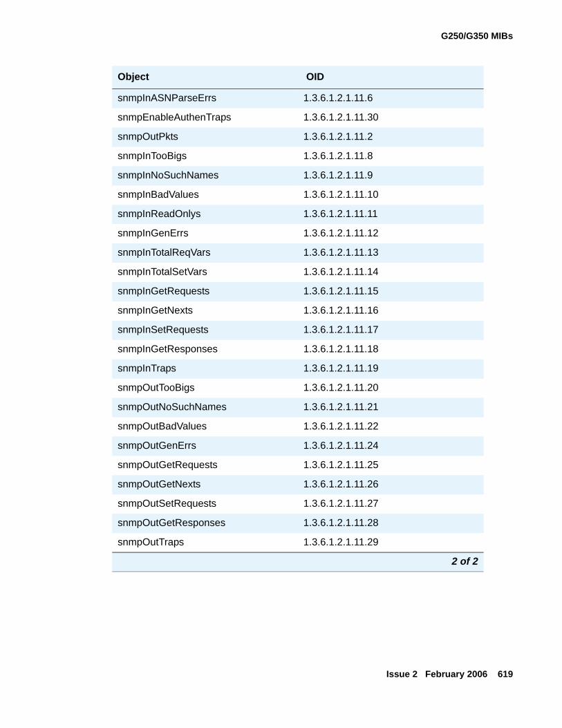
G250/G350 MIBs
Issue 2 February 2006 619
snmpInASNParseErrs 1.3.6.1.2.1.11.6
snmpEnableAuthenTraps 1.3.6.1.2.1.11.30
snmpOutPkts 1.3.6.1.2.1.11.2
snmpInTooBigs 1.3.6.1.2.1.11.8
snmpInNoSuchNames 1.3.6.1.2.1.11.9
snmpInBadValues 1.3.6.1.2.1.11.10
snmpInReadOnlys 1.3.6.1.2.1.11.11
snmpInGenErrs 1.3.6.1.2.1.11.12
snmpInTotalReqVars 1.3.6.1.2.1.11.13
snmpInTotalSetVars 1.3.6.1.2.1.11.14
snmpInGetRequests 1.3.6.1.2.1.11.15
snmpInGetNexts 1.3.6.1.2.1.11.16
snmpInSetRequests 1.3.6.1.2.1.11.17
snmpInGetResponses 1.3.6.1.2.1.11.18
snmpInTraps 1.3.6.1.2.1.11.19
snmpOutTooBigs 1.3.6.1.2.1.11.20
snmpOutNoSuchNames 1.3.6.1.2.1.11.21
snmpOutBadValues 1.3.6.1.2.1.11.22
snmpOutGenErrs 1.3.6.1.2.1.11.24
snmpOutGetRequests 1.3.6.1.2.1.11.25
snmpOutGetNexts 1.3.6.1.2.1.11.26
snmpOutSetRequests 1.3.6.1.2.1.11.27
snmpOutGetResponses 1.3.6.1.2.1.11.28
snmpOutTraps 1.3.6.1.2.1.11.29
Object OID
2 of 2
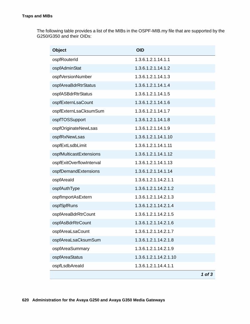
Traps and MIBs
620 Administration for the Avaya G250 and Avaya G350 Media Gateways
The following table provides a list of the MIBs in the OSPF-MIB.my file that are supported by the G250/G350 and their OIDs:
Object OID
ospfRouterId 1.3.6.1.2.1.14.1.1
ospfAdminStat 1.3.6.1.2.1.14.1.2
ospfVersionNumber 1.3.6.1.2.1.14.1.3
ospfAreaBdrRtrStatus 1.3.6.1.2.1.14.1.4
ospfASBdrRtrStatus 1.3.6.1.2.1.14.1.5
ospfExternLsaCount 1.3.6.1.2.1.14.1.6
ospfExternLsaCksumSum 1.3.6.1.2.1.14.1.7
ospfTOSSupport 1.3.6.1.2.1.14.1.8
ospfOriginateNewLsas 1.3.6.1.2.1.14.1.9
ospfRxNewLsas 1.3.6.1.2.1.14.1.10
ospfExtLsdbLimit 1.3.6.1.2.1.14.1.11
ospfMulticastExtensions 1.3.6.1.2.1.14.1.12
ospfExitOverflowInterval 1.3.6.1.2.1.14.1.13
ospfDemandExtensions 1.3.6.1.2.1.14.1.14
ospfAreaId 1.3.6.1.2.1.14.2.1.1
ospfAuthType 1.3.6.1.2.1.14.2.1.2
ospfImportAsExtern 1.3.6.1.2.1.14.2.1.3
ospfSpfRuns 1.3.6.1.2.1.14.2.1.4
ospfAreaBdrRtrCount 1.3.6.1.2.1.14.2.1.5
ospfAsBdrRtrCount 1.3.6.1.2.1.14.2.1.6
ospfAreaLsaCount 1.3.6.1.2.1.14.2.1.7
ospfAreaLsaCksumSum 1.3.6.1.2.1.14.2.1.8
ospfAreaSummary 1.3.6.1.2.1.14.2.1.9
ospfAreaStatus 1.3.6.1.2.1.14.2.1.10
ospfLsdbAreaId 1.3.6.1.2.1.14.4.1.1
1 of 3
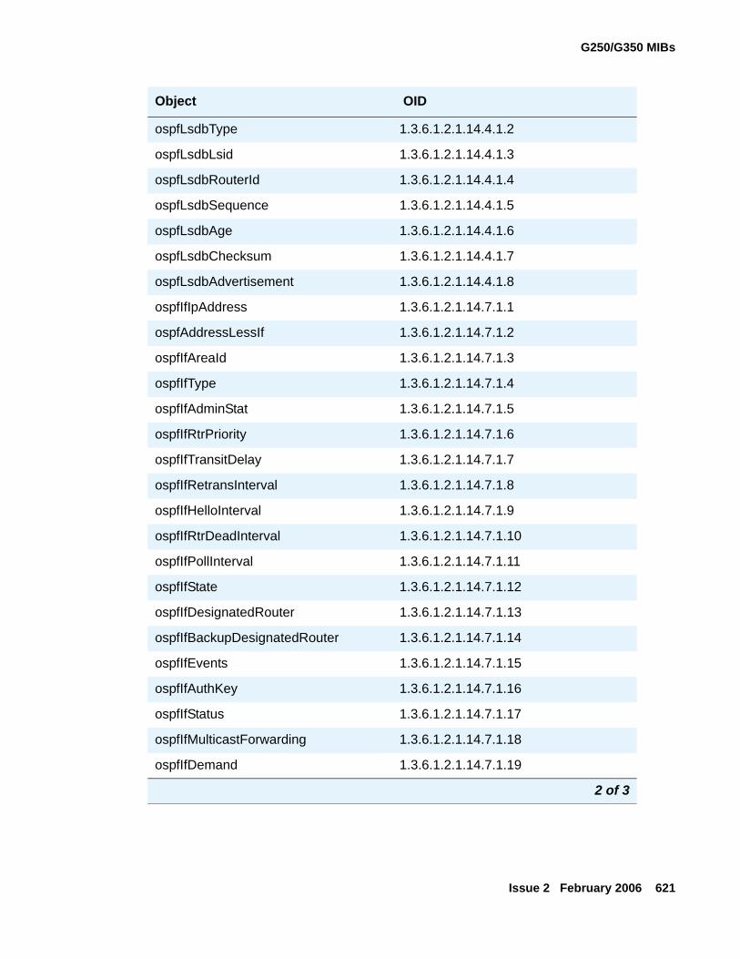
G250/G350 MIBs
Issue 2 February 2006 621
ospfLsdbType 1.3.6.1.2.1.14.4.1.2
ospfLsdbLsid 1.3.6.1.2.1.14.4.1.3
ospfLsdbRouterId 1.3.6.1.2.1.14.4.1.4
ospfLsdbSequence 1.3.6.1.2.1.14.4.1.5
ospfLsdbAge 1.3.6.1.2.1.14.4.1.6
ospfLsdbChecksum 1.3.6.1.2.1.14.4.1.7
ospfLsdbAdvertisement 1.3.6.1.2.1.14.4.1.8
ospfIfIpAddress 1.3.6.1.2.1.14.7.1.1
ospfAddressLessIf 1.3.6.1.2.1.14.7.1.2
ospfIfAreaId 1.3.6.1.2.1.14.7.1.3
ospfIfType 1.3.6.1.2.1.14.7.1.4
ospfIfAdminStat 1.3.6.1.2.1.14.7.1.5
ospfIfRtrPriority 1.3.6.1.2.1.14.7.1.6
ospfIfTransitDelay 1.3.6.1.2.1.14.7.1.7
ospfIfRetransInterval 1.3.6.1.2.1.14.7.1.8
ospfIfHelloInterval 1.3.6.1.2.1.14.7.1.9
ospfIfRtrDeadInterval 1.3.6.1.2.1.14.7.1.10
ospfIfPollInterval 1.3.6.1.2.1.14.7.1.11
ospfIfState 1.3.6.1.2.1.14.7.1.12
ospfIfDesignatedRouter 1.3.6.1.2.1.14.7.1.13
ospfIfBackupDesignatedRouter 1.3.6.1.2.1.14.7.1.14
ospfIfEvents 1.3.6.1.2.1.14.7.1.15
ospfIfAuthKey 1.3.6.1.2.1.14.7.1.16
ospfIfStatus 1.3.6.1.2.1.14.7.1.17
ospfIfMulticastForwarding 1.3.6.1.2.1.14.7.1.18
ospfIfDemand 1.3.6.1.2.1.14.7.1.19
Object OID
2 of 3
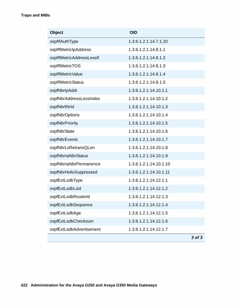
Traps and MIBs
622 Administration for the Avaya G250 and Avaya G350 Media Gateways
ospfIfAuthType 1.3.6.1.2.1.14.7.1.20
ospfIfMetricIpAddress 1.3.6.1.2.1.14.8.1.1
ospfIfMetricAddressLessIf 1.3.6.1.2.1.14.8.1.2
ospfIfMetricTOS 1.3.6.1.2.1.14.8.1.3
ospfIfMetricValue 1.3.6.1.2.1.14.8.1.4
ospfIfMetricStatus 1.3.6.1.2.1.14.8.1.5
ospfNbrIpAddr 1.3.6.1.2.1.14.10.1.1
ospfNbrAddressLessIndex 1.3.6.1.2.1.14.10.1.2
ospfNbrRtrId 1.3.6.1.2.1.14.10.1.3
ospfNbrOptions 1.3.6.1.2.1.14.10.1.4
ospfNbrPriority 1.3.6.1.2.1.14.10.1.5
ospfNbrState 1.3.6.1.2.1.14.10.1.6
ospfNbrEvents 1.3.6.1.2.1.14.10.1.7
ospfNbrLsRetransQLen 1.3.6.1.2.1.14.10.1.8
ospfNbmaNbrStatus 1.3.6.1.2.1.14.10.1.9
ospfNbmaNbrPermanence 1.3.6.1.2.1.14.10.1.10
ospfNbrHelloSuppressed 1.3.6.1.2.1.14.10.1.11
ospfExtLsdbType 1.3.6.1.2.1.14.12.1.1
ospfExtLsdbLsid 1.3.6.1.2.1.14.12.1.2
ospfExtLsdbRouterId 1.3.6.1.2.1.14.12.1.3
ospfExtLsdbSequence 1.3.6.1.2.1.14.12.1.4
ospfExtLsdbAge 1.3.6.1.2.1.14.12.1.5
ospfExtLsdbChecksum 1.3.6.1.2.1.14.12.1.6
ospfExtLsdbAdvertisement 1.3.6.1.2.1.14.12.1.7
Object OID
3 of 3
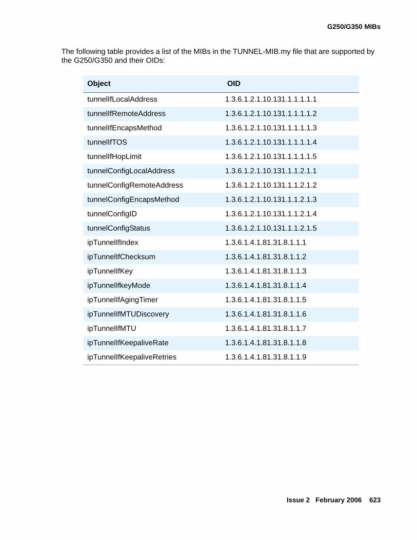
G250/G350 MIBs
Issue 2 February 2006 623
The following table provides a list of the MIBs in the TUNNEL-MIB.my file that are supported by the G250/G350 and their OIDs:
Object OID
tunnelIfLocalAddress 1.3.6.1.2.1.10.131.1.1.1.1.1
tunnelIfRemoteAddress 1.3.6.1.2.1.10.131.1.1.1.1.2
tunnelIfEncapsMethod 1.3.6.1.2.1.10.131.1.1.1.1.3
tunnelIfTOS 1.3.6.1.2.1.10.131.1.1.1.1.4
tunnelIfHopLimit 1.3.6.1.2.1.10.131.1.1.1.1.5
tunnelConfigLocalAddress 1.3.6.1.2.1.10.131.1.1.2.1.1
tunnelConfigRemoteAddress 1.3.6.1.2.1.10.131.1.1.2.1.2
tunnelConfigEncapsMethod 1.3.6.1.2.1.10.131.1.1.2.1.3
tunnelConfigID 1.3.6.1.2.1.10.131.1.1.2.1.4
tunnelConfigStatus 1.3.6.1.2.1.10.131.1.1.2.1.5
ipTunnelIfIndex 1.3.6.1.4.1.81.31.8.1.1.1
ipTunnelIfChecksum 1.3.6.1.4.1.81.31.8.1.1.2
ipTunnelIfKey 1.3.6.1.4.1.81.31.8.1.1.3
ipTunnelIfkeyMode 1.3.6.1.4.1.81.31.8.1.1.4
ipTunnelIfAgingTimer 1.3.6.1.4.1.81.31.8.1.1.5
ipTunnelIfMTUDiscovery 1.3.6.1.4.1.81.31.8.1.1.6
ipTunnelIfMTU 1.3.6.1.4.1.81.31.8.1.1.7
ipTunnelIfKeepaliveRate 1.3.6.1.4.1.81.31.8.1.1.8
ipTunnelIfKeepaliveRetries 1.3.6.1.4.1.81.31.8.1.1.9

Traps and MIBs
624 Administration for the Avaya G250 and Avaya G350 Media Gateways
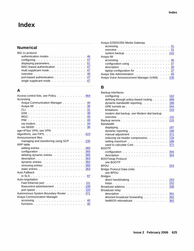
Issue 2 February 2006 625
Index
Index
Numerical802.1x protocol
authentication modes . . . . . . . . . . . . . . 46configuring . . . . . . . . . . . . . . . . . . . 47displaying parameters. . . . . . . . . . . . . . 51MAC-based authentication . . . . . . . . . . . 47multi supplicant mode . . . . . . . . . . . . . . 47overview . . . . . . . . . . . . . . . . . . . . 46port-based authentication . . . . . . . . . . . . 47single supplicant mode . . . . . . . . . . . . . 47
AAccess control lists, see Policy . . . . . . . . . . . 464Accessing
Avaya Communication Manager . . . . . . . . . 40Avaya IW . . . . . . . . . . . . . . . . . . . 36CLI . . . . . . . . . . . . . . . . . . . . . . 31GIW . . . . . . . . . . . . . . . . . . . . . . 38MGC. . . . . . . . . . . . . . . . . . . . . . 40PIM . . . . . . . . . . . . . . . . . . . . . . 40via modem . . . . . . . . . . . . . . . . . . . 34via S8300 . . . . . . . . . . . . . . . . . . . 36
age>IPSec VPN, see VPNAlgorithms, see FIPS. . . . . . . . . . . . . . . . 523Announcement files
managing and transferring using SCP . . . . . . 235ARP table
adding entries . . . . . . . . . . . . . . . . . 365configuration . . . . . . . . . . . . . . . . . . 365deleting dynamic entries . . . . . . . . . . . . 365description . . . . . . . . . . . . . . . . . . . 363dynamic entries. . . . . . . . . . . . . . . . . 364removing entries . . . . . . . . . . . . . . . . 365static entries . . . . . . . . . . . . . . . . . . 363
Auto Fallbackin SLS . . . . . . . . . . . . . . . . . . . . . 87
Auto-negotiationFast Ethernet port . . . . . . . . . . . . . . . 111flowcontrol advertisement . . . . . . . . . . . . 109port speed . . . . . . . . . . . . . . . . . . . 110
Autonomous System Boundary Router . . . . . . . 371Avaya Communication Manager
accessing . . . . . . . . . . . . . . . . . . . 40functions . . . . . . . . . . . . . . . . . . . . 40
Avaya G250/G350 Media Gatewayaccessing. . . . . . . . . . . . . . . . . . . . 31overview . . . . . . . . . . . . . . . . . . . . 31system backup . . . . . . . . . . . . . . . . 215
Avaya IWaccessing. . . . . . . . . . . . . . . . . . . . 36configuration using . . . . . . . . . . . . . . . 37description . . . . . . . . . . . . . . . . . . . 36laptop configuration for . . . . . . . . . . . . . 37
Avaya Site Administration . . . . . . . . . . . . . . 40Avaya Voice Announcement Manager (VAM). . . . 235
BBackup interfaces
configuring . . . . . . . . . . . . . . . . . . 162defining through policy-based routing . . . . . . 489dynamic bandwidth reporting . . . . . . . . . . 186GRE tunnels as . . . . . . . . . . . . . . . . 344limitations . . . . . . . . . . . . . . . . . . . 163modem dial backup, see Modem dial backupoverview . . . . . . . . . . . . . . . . . . . .111
Backup service . . . . . . . . . . . . . . . . . . 215Bandwidth
displaying . . . . . . . . . . . . . . . . . . . 187dynamic reporting . . . . . . . . . . . . . . . 186manual adjustment . . . . . . . . . . . . . . 371reducing via header compression. . . . . . . . 134setting maximum . . . . . . . . . . . . . . . 186used to calculate Cost . . . . . . . . . . . . . 371
BOOTPconfiguration . . . . . . . . . . . . . . . . . 355description . . . . . . . . . . . . . . . . . . 354
BOOTstrap Protocolsee BOOTP
BPDU . . . . . . . . . . . . . . . . . . . . . . 253Bridge Protocol Data Units
see BPDUBridges
direct handshaking . . . . . . . . . . . . . . 253loops . . . . . . . . . . . . . . . . . . . . . 252
Broadcast address . . . . . . . . . . . . . . . . 336Broadcast relay
description . . . . . . . . . . . . . . . . . . 361directed broadcast forwarding . . . . . . . . . 362NetBIOS rebroadcast . . . . . . . . . . . . . 362
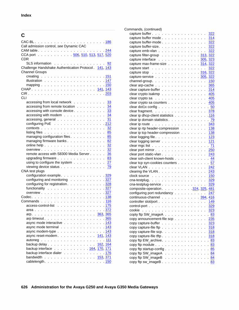
626 Administration for the Avaya G250 and Avaya G350 Media Gateways
Index
CCAC-BL . . . . . . . . . . . . . . . . . . . . . . 186Call admission control, see Dynamic CACCAM table . . . . . . . . . . . . . . . . . . . . . 244CCA port . . . . . . . . . . . 506, 510, 513, 517, 520CDR
SLS information . . . . . . . . . . . . . . . . 92Challenge Handshake Authentication Protocol . 141, 143Channel Groups
creating . . . . . . . . . . . . . . . . . . . . 151illustration . . . . . . . . . . . . . . . . . . . 147mapping . . . . . . . . . . . . . . . . . . . . 150
CHAP . . . . . . . . . . . . . . . . . . . . 141, 143CIR . . . . . . . . . . . . . . . . . . . . . . . . 203CLI
accessing from local network . . . . . . . . . . 33accessing from remote location . . . . . . . . . 34accessing with console device . . . . . . . . . . 33accessing with modem . . . . . . . . . . . . . 34accessing, general . . . . . . . . . . . . . . . 31configuring PoE . . . . . . . . . . . . . . . . 212contexts . . . . . . . . . . . . . . . . . . . . 32listing files . . . . . . . . . . . . . . . . . . . 85managing configuration files . . . . . . . . . . . 85managing firmware banks . . . . . . . . . . . . 82online help . . . . . . . . . . . . . . . . . . . 32overview . . . . . . . . . . . . . . . . . . . . 32remote access with S8300 Media Server . . . . . 36upgrading firmware . . . . . . . . . . . . . . . 83using to configure the system . . . . . . . . . . 27viewing device status . . . . . . . . . . . . . . 79
CNA test plugsconfiguration example. . . . . . . . . . . . . . 329configuring and monitoring . . . . . . . . . . . 327configuring for registration . . . . . . . . . . . . 328functionality . . . . . . . . . . . . . . . . . . 327overview . . . . . . . . . . . . . . . . . . . . 327
Codec. . . . . . . . . . . . . . . . . . . . . . . 138Commands . . . . . . . . . . . . . . . . . . . . 116
access-control-list . . . . . . . . . . . . . . . 175area . . . . . . . . . . . . . . . . . . . . . . 372arp. . . . . . . . . . . . . . . . . . . . 363, 365arp timeout . . . . . . . . . . . . . . . . . . . 365async mode interactive . . . . . . . . . . . . . 143async mode terminal . . . . . . . . . . . . . . 143async modem-type . . . . . . . . . . . . . . . 143async reset-modem. . . . . . . . . . . . 141, 143autoneg . . . . . . . . . . . . . . . . . . . . 111backup delay . . . . . . . . . . . . . . . 162, 164backup interface . . . . . . . . . . . 164, 170, 171backup interface dialer . . . . . . . . . . . . . 176bandwidth . . . . . . . . . . . . . . . . 153, 371cablelength. . . . . . . . . . . . . . . . . . . 150
Commands, (continued)capture buffer . . . . . . . . . . . . . . . . . 322capture buffer mode . . . . . . . . . . . . . . 314capture buffer-mode . . . . . . . . . . . . . . 322capture buffer-size. . . . . . . . . . . . . . . 322capture emb-vlan . . . . . . . . . . . . . . . 322capture filter-group . . . . . . . . . . . . 313, 322capture interface . . . . . . . . . . . . . 305, 323capture max-frame-size . . . . . . . . . . 314, 322capture start . . . . . . . . . . . . . . . . . 322capture stop . . . . . . . . . . . . . . . 316, 322capture-service . . . . . . . . . . . . . . 305, 322channel-group. . . . . . . . . . . . . . . . . 150clear arp-cache . . . . . . . . . . . . . . . . 365clear capture-buffer . . . . . . . . . . . . . . 314clear crypto isakmp . . . . . . . . . . . . . . 405clear crypto sa . . . . . . . . . . . . . . . . 405clear crypto sa counters . . . . . . . . . . . . 405clear dot1x config . . . . . . . . . . . . . . . . 50clear fragment. . . . . . . . . . . . . . . . . 378clear ip dhcp-client statistics . . . . . . . . . . .116clear ip domain statistics . . . . . . . . . . . . . 79clear ip route . . . . . . . . . . . . . . . . . 343clear ip rtp header-compression . . . . . . . . 138clear ip tcp header-compression . . . . . . . . 138clear logging file . . . . . . . . . . . . . . . . 123clear logging server . . . . . . . . . . . . . . 121clear mgc list . . . . . . . . . . . . . . . . . . 71clear port mirror . . . . . . . . . . . . . . . . 250clear port static-vlan . . . . . . . . . . . . . . 243clear ssh-client known-hosts . . . . . . . . . . . 44clear tcp syn-cookies counters . . . . . . . . . . 57clear VLAN . . . . . . . . . . . . . . . . . . 242clearing the VLAN . . . . . . . . . . . . . . . 243clock source . . . . . . . . . . . . . . . . . 150cna-testplug. . . . . . . . . . . . . . . . . . 329cna-testplug-service . . . . . . . . . . . . . . 329composite-operation . . . . . . . . . .324, 325, 481configuring port redundancy . . . . . . . . . . 247continuous-channel . . . . . . . . . . . . 394, 416controller slot/port . . . . . . . . . . . . . . . 149control-port . . . . . . . . . . . . . . . . . . 329cookie . . . . . . . . . . . . . . . . . . . . 323copty ftp SW_imageA . . . . . . . . . . . . . . 83copy announcement-file scp . . . . . . . . . . 235copy capture-buffer . . . . . . . . . . . . . . 323copy capture-file ftp . . . . . . . . . . . . . . 318copy capture-file scp. . . . . . . . . . . . . . 318copy capture-file tftp . . . . . . . . . . . . . . 318copy ftp EW_archive. . . . . . . . . . . . . . . 83copy ftp module . . . . . . . . . . . . . . . . . 83copy ftp startup-config . . . . . . . . . . . . . . 85copy ftp SW_imageA . . . . . . . . . . . . . . 84copy ftp SW_imageB . . . . . . . . . . . . . . 84copy ftp sw_imageB . . . . . . . . . . . . . . . 83

Issue 2 February 2006 627
Index
Commands, (continued)copy running-config ftp . . . . . . . . . . . . . 85copy running-config startup-config . 82, 149, 152, 154,
350, 492copy running-config tftp . . . . . . . . . . . . . 85copy scp announcement-file . . . . . . . . . . . 235copy startup-config ftp . . . . . . . . . . . . . 85copy startup-config tftp . . . . . . . . . . . . . 85copy tftp EW_archive . . . . . . . . . . . . .83, 84copy tftp license-file . . . . . . . . . . . . . . . 542copy tftp module . . . . . . . . . . . . . . .83, 84copy tftp startup-confit . . . . . . . . . . . . . 85copy tftp SW_imageA . . . . . . . . . . . . . . 83copy tftp SW_imageB . . . . . . . . . . . . . . 83create SNMPv3 user . . . . . . . . . . . . . . 227creating an event entry . . . . . . . . . . . . . 262crypto ipsec df-bit . . . . . . . . . . . . . . . . 403crypto ipsec minimal pmtu . . . . . . . . . . . . 403crypto ipsec transform-set . . . . 390, 445, 453, 553crypto isakmp invalid-spi-recovery . . . . . . . . 401crypto isakmp peer . . . . . . . . . . . . 391, 552crypto isakmp peer address . . . . . . . . 445, 453crypto isakmp peer-group . . . . . . . . . 395, 453crypto isakmp policy . . . . . . . . . 445, 453, 552crypto key generate dsa. . . . . . . . . . . . . 44crypto map . . . . . . . . . . . . . . . . 396, 553cyrpto isakmp policy . . . . . . . . . . . . . . 389default-metric. . . . . . . . . . . . . . . 369, 372description . . . . . . . . . . . . . . 75, 389, 395destination-ip . . . . . . . . . . 308, 324, 398, 475dialer modem-interface . . . . . . . . . . . . . 176dialer persisten initial delay . . . . . . . . . . . 169dialer persistent delay. . . . . . . . . . . . . . 175dialer persistent initial delay . . . . . . . . . . . 175dialer persistent max-attempts . . . . . . . . . . 169dialer string. . . . . . . . . . . . . . . . 168, 176disable link encryption . . . . . . . . . . . . . 543disconnect ssh . . . . . . . . . . . . . . . . . 44distribution list . . . . . . . . . . . . . . . . . 368distribution-list . . . . . . . . . . . . . . . . . 369dos-classification . . . . . . . . . . . . . . . . 62dscp . . . . . . . . . . . . . . 190, 308, 325, 478ds-mode . . . . . . . . . . . . . . . . . . . . 149duplex . . . . . . . . . . . . . . . . . . . . . 111dynamic-cac bbl . . . . . . . . . . . . . . . . 186encapsulation frame-relay . . . . . . . . . . . . 159encapsulation ppp . . . . . . . . . . . . . . . 155encapsulation pppoe . . . . . . . . . . . . . . 156encaspulation ppoe . . . . . . . . . . . . . . . 414encryption . . . . . . . . . . . . . . . . . . . 389enhanced security . . . . . . . . . . . . 539, 548erase announcement-file . . . . . . . . . . . . 235exit . . . . . . . . . . . . . . . . . . . . . . 391fail-retries . . . . . . . . . . . . . . . . . . . 190fair-queue-limit . . . . . . . . . . . . . . . . . 140fair-voip-queue . . . . . . . . . . . . . . . . . 140
Commands, (continued)fragment chain . . . . . . . . . . . . . . . . 378fragment size . . . . . . . . . . . . . . . . . 378fragment timeout . . . . . . . . . . . . . . . 378fragments . . . . . . . . . . . . . . . . . . . 378frame-relay interface-dlci. . . . . . . . . . . . 160frame-relay lmi . . . . . . . . . . . . . . . . 159frame-relay priority-dlci-group . . . . . . . 160, 204frame-relay traffic-shaping . . . . . . . . . 159, 203framing . . . . . . . . . . . . . . . . . . . . 150frequency . . . . . . . . . . . . . . . . . . . 189group . . . . . . . . . . . . . . . . . . . . . 389hash . . . . . . . . . . . . . . . . . . . . . 389help . . . . . . . . . . . . . . . . . . . . . . 32icc-vlan . . . . . . . . . . . . . . . . . . . . 243icmp . . . . . . . . . . . . . . . . . . . 311, 325idle characters . . . . . . . . . . . . . . . . 153ignore dcd . . . . . . . . . . . . . . . . . . 154initiate mode aggressive . . . . . . . . . . . . 392inteface vlan 1 . . . . . . . . . . . . . . . . . 66interface . . . . . . . . . . . . . . . . 65, 66, 336interface console . . . . . . . . . . . . . 143, 176interface dialer . . . . . . . . . . . . . . 168, 175interface FastEthernet . . . . . . . . . . . . . .110interface loopback . . . . . . . . . . . . . . . 175interface Serial . . . . . . . . . 151, 153, 155, 159Interface tunnel . . . . . . . . . . . . . . . . 349interface usb-modem . . . . . . . . . . . . . 141interface vlan . . . . . . . . . . . . . . . . . 243invert txclock . . . . . . . . . . . . . . . . . 154ip access group in . . . . . . . . . . . . . . . 470ip access group out . . . . . . . . . . . . . . 470ip access-control list . . . . . . . . . . . . . . 467ip access-control-list . . . . . . . . . . . . . . 401ip access-group . . . . . . . . . . . . . . . . 176ip address . . . . 65, 141, 143, 154, 155, 160, 336ip address dhcp . . . . . . . . . . . . . . . 77, 114ip address negotiated . . . . . . . . . . . 157, 414ip admin-state . . . . . . . . . . . . . . . . . 336ip bootp-dhcp network . . . . . . . . . . . . . 355ip bootp-dhcp relay . . . . . . . . . . . . . . 355ip bootp-dhcp server. . . . . . . . . . . . . . 355ip broadcast-address . . . . . . . . . . . . . 336ip capture-list . . . . . . . . . . . . . . . 306, 322ip crypto list . . . . . . . . . . . . . . . . . . 553ip crypto-group . . . . . . . . . . . . . . 416, 555ip crypto-group crypto-list-id . . . . . . . . . . 400ip crypto-list . . . . . . . . . . . . . . . . . . 397ip default-gateway . . . . . . . . . . . . . .67, 343ip dhcp client client-id . . . . . . . . . . . . . .113ip dhcp client hostname . . . . . . . . . . . . .113ip dhcp client lease . . . . . . . . . . . . . . .113ip dhcp client request . . . . . . . . . . . 113, 445ip dhcp client route track . . . . . . . . . . . . .114ip directed-broadcast . . . . . . . . . . . . . 362
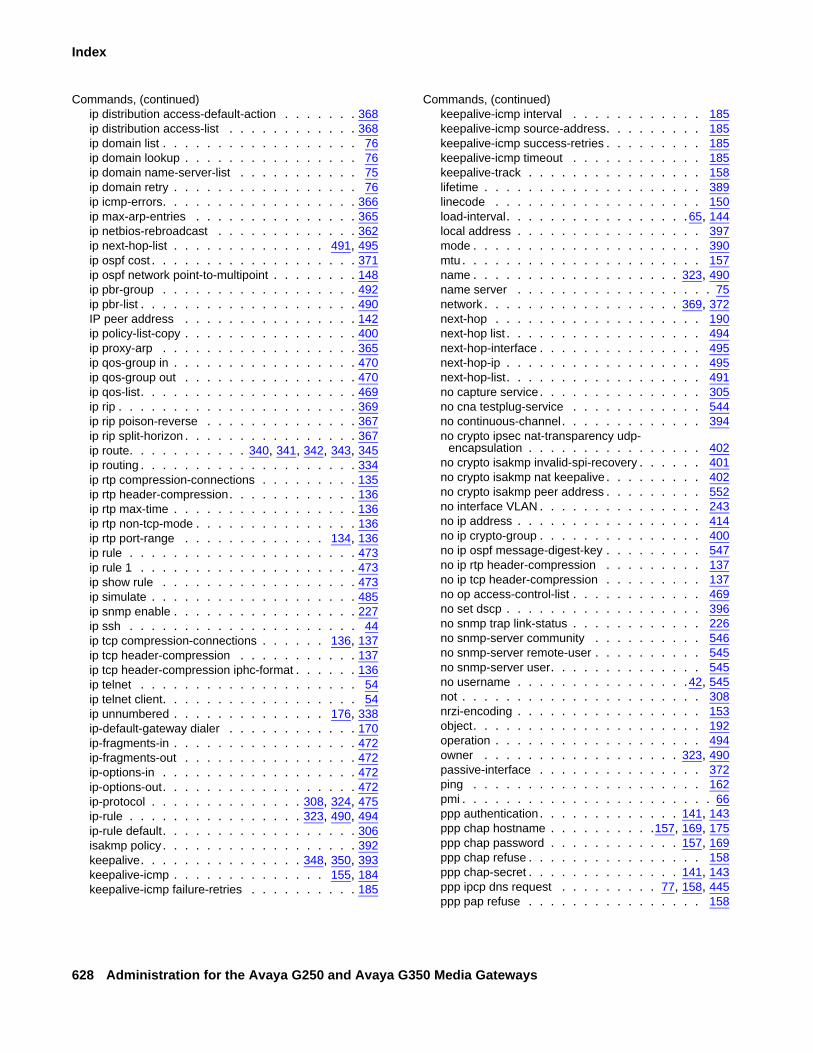
628 Administration for the Avaya G250 and Avaya G350 Media Gateways
Index
Commands, (continued)ip distribution access-default-action . . . . . . . 368ip distribution access-list . . . . . . . . . . . . 368ip domain list . . . . . . . . . . . . . . . . . . 76ip domain lookup . . . . . . . . . . . . . . . . 76ip domain name-server-list . . . . . . . . . . . 75ip domain retry . . . . . . . . . . . . . . . . . 76ip icmp-errors. . . . . . . . . . . . . . . . . . 366ip max-arp-entries . . . . . . . . . . . . . . . 365ip netbios-rebroadcast . . . . . . . . . . . . . 362ip next-hop-list . . . . . . . . . . . . . . 491, 495ip ospf cost . . . . . . . . . . . . . . . . . . . 371ip ospf network point-to-multipoint . . . . . . . . 148ip pbr-group . . . . . . . . . . . . . . . . . . 492ip pbr-list . . . . . . . . . . . . . . . . . . . . 490IP peer address . . . . . . . . . . . . . . . . 142ip policy-list-copy . . . . . . . . . . . . . . . . 400ip proxy-arp . . . . . . . . . . . . . . . . . . 365ip qos-group in . . . . . . . . . . . . . . . . . 470ip qos-group out . . . . . . . . . . . . . . . . 470ip qos-list. . . . . . . . . . . . . . . . . . . . 469ip rip . . . . . . . . . . . . . . . . . . . . . . 369ip rip poison-reverse . . . . . . . . . . . . . . 367ip rip split-horizon . . . . . . . . . . . . . . . . 367ip route. . . . . . . . . . . 340, 341, 342, 343, 345ip routing . . . . . . . . . . . . . . . . . . . . 334ip rtp compression-connections . . . . . . . . . 135ip rtp header-compression. . . . . . . . . . . . 136ip rtp max-time . . . . . . . . . . . . . . . . . 136ip rtp non-tcp-mode . . . . . . . . . . . . . . . 136ip rtp port-range . . . . . . . . . . . . . 134, 136ip rule . . . . . . . . . . . . . . . . . . . . . 473ip rule 1 . . . . . . . . . . . . . . . . . . . . 473ip show rule . . . . . . . . . . . . . . . . . . 473ip simulate . . . . . . . . . . . . . . . . . . . 485ip snmp enable . . . . . . . . . . . . . . . . . 227ip ssh . . . . . . . . . . . . . . . . . . . . . 44ip tcp compression-connections . . . . . . 136, 137ip tcp header-compression . . . . . . . . . . . 137ip tcp header-compression iphc-format . . . . . . 136ip telnet . . . . . . . . . . . . . . . . . . . . 54ip telnet client. . . . . . . . . . . . . . . . . . 54ip unnumbered . . . . . . . . . . . . . . 176, 338ip-default-gateway dialer . . . . . . . . . . . . 170ip-fragments-in . . . . . . . . . . . . . . . . . 472ip-fragments-out . . . . . . . . . . . . . . . . 472ip-options-in . . . . . . . . . . . . . . . . . . 472ip-options-out. . . . . . . . . . . . . . . . . . 472ip-protocol . . . . . . . . . . . . . . 308, 324, 475ip-rule . . . . . . . . . . . . . . . . 323, 490, 494ip-rule default. . . . . . . . . . . . . . . . . . 306isakmp policy . . . . . . . . . . . . . . . . . . 392keepalive. . . . . . . . . . . . . . . 348, 350, 393keepalive-icmp . . . . . . . . . . . . . . 155, 184keepalive-icmp failure-retries . . . . . . . . . . 185
Commands, (continued)keepalive-icmp interval . . . . . . . . . . . . 185keepalive-icmp source-address. . . . . . . . . 185keepalive-icmp success-retries . . . . . . . . . 185keepalive-icmp timeout . . . . . . . . . . . . 185keepalive-track . . . . . . . . . . . . . . . . 158lifetime . . . . . . . . . . . . . . . . . . . . 389linecode . . . . . . . . . . . . . . . . . . . 150load-interval. . . . . . . . . . . . . . . . .65, 144local address . . . . . . . . . . . . . . . . . 397mode . . . . . . . . . . . . . . . . . . . . . 390mtu . . . . . . . . . . . . . . . . . . . . . . 157name . . . . . . . . . . . . . . . . . . . 323, 490name server . . . . . . . . . . . . . . . . . . 75network . . . . . . . . . . . . . . . . . . 369, 372next-hop . . . . . . . . . . . . . . . . . . . 190next-hop list . . . . . . . . . . . . . . . . . . 494next-hop-interface . . . . . . . . . . . . . . . 495next-hop-ip . . . . . . . . . . . . . . . . . . 495next-hop-list. . . . . . . . . . . . . . . . . . 491no capture service. . . . . . . . . . . . . . . 305no cna testplug-service . . . . . . . . . . . . 544no continuous-channel. . . . . . . . . . . . . 394no crypto ipsec nat-transparency udp-
encapsulation . . . . . . . . . . . . . . . . 402no crypto isakmp invalid-spi-recovery . . . . . . 401no crypto isakmp nat keepalive . . . . . . . . . 402no crypto isakmp peer address . . . . . . . . . 552no interface VLAN . . . . . . . . . . . . . . . 243no ip address . . . . . . . . . . . . . . . . . 414no ip crypto-group . . . . . . . . . . . . . . . 400no ip ospf message-digest-key . . . . . . . . . 547no ip rtp header-compression . . . . . . . . . 137no ip tcp header-compression . . . . . . . . . 137no op access-control-list . . . . . . . . . . . . 469no set dscp . . . . . . . . . . . . . . . . . . 396no snmp trap link-status . . . . . . . . . . . . 226no snmp-server community . . . . . . . . . . 546no snmp-server remote-user . . . . . . . . . . 545no snmp-server user. . . . . . . . . . . . . . 545no username . . . . . . . . . . . . . . . .42, 545not . . . . . . . . . . . . . . . . . . . . . . 308nrzi-encoding . . . . . . . . . . . . . . . . . 153object. . . . . . . . . . . . . . . . . . . . . 192operation . . . . . . . . . . . . . . . . . . . 494owner . . . . . . . . . . . . . . . . . . 323, 490passive-interface . . . . . . . . . . . . . . . 372ping . . . . . . . . . . . . . . . . . . . . . 162pmi . . . . . . . . . . . . . . . . . . . . . . . 66ppp authentication. . . . . . . . . . . . . 141, 143ppp chap hostname . . . . . . . . . .157, 169, 175ppp chap password . . . . . . . . . . . . 157, 169ppp chap refuse . . . . . . . . . . . . . . . . 158ppp chap-secret . . . . . . . . . . . . . . 141, 143ppp ipcp dns request . . . . . . . . . 77, 158, 445ppp pap refuse . . . . . . . . . . . . . . . . 158

Issue 2 February 2006 629
Index
Commands, (continued)ppp pap-sent . . . . . . . . . . . . . . . 157, 169ppp timeout ncp . . . . . . . . . . . . . . . . 155ppp timeout retry . . . . . . . . . . . . . . . . 155pppoe-client persistent delay . . . . . . . . . . 158pppoe-client persistent max-attempts . . . . . . 158pppoe-client service name. . . . . . . . . . . . 157pppoe-client wait-for-ipcp . . . . . . . . . . . . 158pre-shared-key . . . . . . . . . . . . . . . . . 392priority-queue. . . . . . . . . . . . . . . . . . 140protect crypto-map crypto-map-id . . . . . . . . 399range . . . . . . . . . . . . . . . . . . . . . 476redistribute . . . . . . . . . . . . . . 370, 372, 373release dhcp . . . . . . . . . . . . . . . . . . 115rename announcement-file . . . . . . . . . . . 235renew dhcp. . . . . . . . . . . . . . . . . . . 115reset . . . . . . . . . . . . . . . . . . . . . . 66rmon alarm . . . . . . . . . . . . . . . . . . . 262rmon event . . . . . . . . . . . . . . . . . . . 262rmon history . . . . . . . . . . . . . . . . . . 262router ospf . . . . . . . . . . . . . . . . 176, 372router rip . . . . . . . . . . . . . . . . . . . . 370router vrrp . . . . . . . . . . . . . . . . . . . 376rtp-echo-port . . . . . . . . . . . . . . . . . . 329rtp-stat clear . . . . . . . . . . . . . . . 269, 302rtp-stat event-threshold . . . . . . . . . . 269, 302rtp-stat fault . . . . . . . . . . . . . . . 273, 302rtp-stat min-stat-win . . . . . . . . . . . . 272, 302rtp-stat qos-trap . . . . . . . . . . . . . 272, 302rtp-stat qos-trap-rate-limit . . . . . . . . . 273, 303rtp-stat service . . . . . . . . . . . . . . . . . 303rtp-stat threshold . . . . . . . . . . . . . 269, 302rtp-stat-service . . . . . . . . . . . . . . . . . 269rtp-test-port. . . . . . . . . . . . . . . . . . . 329rtr . . . . . . . . . . . . . . . . . . . . . . . 189rtr-schedule . . . . . . . . . . . . . . . . . . 191scheduler . . . . . . . . . . . . . . . . . . . 329self-identity . . . . . . . . . . . . . . . . . . . 393session icc . . . . . . . . . . . . . . . . . . . 72session mgc . . . . . . . . . . . . . . . . 72, 318set boot bank. . . . . . . . . . . . . . . . . . 82set contact-closure admin . . . . . . . . . . . . 232set contact-closure pulse-duration . . . . . . . . 232set dot1x lldp tlv . . . . . . . . . . . . . . . . 51set dot1x max-req . . . . . . . . . . . . . . . 51set dot1x max-supp-per-port. . . . . . . . . . . 49set dot1x port-mode. . . . . . . . . . . . . . . 49set dot1x quiet-period . . . . . . . . . . . . . . 50set dot1x re-authperiod . . . . . . . . . . . . . 50set dot1x supp-timeout . . . . . . . . . . . . . 51set dot1x system-auth-control . . . . . . . . . . 48set dot1x tx-period . . . . . . . . . . . . . . . 51set dscp . . . . . . . . . . . . . . . . . . . . 396set etr . . . . . . . . . . . . . . . . . . . . . 216set icc-monitoring . . . . . . . . . . . . . . . . 73
Commands, (continued)set lldp system-control . . . . . . . . . . . . . .118set logging file disable . . . . . . . . . . . . . 123set logging file enable . . . . . . . . . . . . . 123set logging server . . . . . . . . . . . . . . . 120set logging server access-level . . . . . . . . . 121set logging server disable . . . . . . . . . . . 121set logging server enable . . . . . . . . . . . 120set logging server facility . . . . . . . . . . . . 120set logging session condition dhcpc . . . . . . .116set logging session condition IPSEC . . . . . . 406set logging session condition ISAKMP . . . . . 405set logging session condituion DNSC . . . . . . . 79set logging session disable. . . . . . . . . . . 125set logging session enable . . . . . 79, 116, 124, 405set mediaserver . . . . . . . . . . . . . . . . . 72set mgc list . . . . . . . . . . . . . . . . . 70, 71set mss-notification rate . . . . . . . . . . . . . 62set peer. . . . . . . . . . . . . . . . . . . . 395set peer group . . . . . . . . . . . . . . . . 396set pfs . . . . . . . . . . . . . . . . . . . . 390set port . . . . . . . . . . . . . . . . . . . . 108set port auto-negotiation-flowcontrol-
advertisement . . . . . . . . . . . . . . . . 109set port classification . . . . . . . . . . . . . 258set port disable . . . . . . . . . . . . . . . . 109set port dot1x initialize . . . . . . . . . . . . . . 50set port dot1x max-req . . . . . . . . . . . . . . 51set port dot1x port-control . . . . . . . . . . . . 48set port dot1x port-mode . . . . . . . . . . . . . 50set port dot1x quiet-period . . . . . . . . . . . . 51set port dot1x re-authentication. . . . . . . . . . 49set port dot1x server-timeout . . . . . . . . . . . 51set port dot1x supp-timeout . . . . . . . . . . . 51set port dot1x tx-period . . . . . . . . . . . . . 51set port duplex . . . . . . . . . . . . . . . . 109set port edge admin state . . . . . . . . . 109, 254set port enable . . . . . . . . . . . . . . . . 109set port level . . . . . . . . . . . . . . . . . 109set port lldp . . . . . . . . . . . . . . . . . . .118set port lldp tlv . . . . . . . . . . . . . . . . .118set port mirror . . . . . . . . . . . . . . . . . 250set port name . . . . . . . . . . . . . . . . . 109set port negotiation . . . . . . . . . . . . . . 109set port point-to-point admin status . . . . . 109, 254set port powerline . . . . . . . . . . . . . . . 212set port powerline diable . . . . . . . . . . . . 212set port powerline priority . . . . . . . . . . . 212set port powerline type. . . . . . . . . . . . . 212set port redundancy . . . . . . . . . . . . . . 248set port redundancy-intervals. . . . . . . . 247, 248set port spantree . . . . . . . . . . . . . . . 255set port speed. . . . . . . . . . . . . . . . . .110set port static-vlan . . . . . . . . . . . . . . . 243set port trap . . . . . . . . . . . . . . . . . . 225set port vlan. . . . . . . . . . . . . . . . 243, 244

630 Administration for the Avaya G250 and Avaya G350 Media Gateways
Index
Commands, (continued)set port vlan-binding-mode . . . . . . . . . . . 244set powerline trap enable . . . . . . . . . . . . 212set prt dot1x re-authenticate . . . . . . . . . . . 50set qos bearer . . . . . . . . . . . . . . . . . 138set qos control . . . . . . . . . . . . . . . . . 138set qos rsvp . . . . . . . . . . . . . . . . . . 140set qos rtcp. . . . . . . . . . . . . . . . . . . 139set qos signal. . . . . . . . . . . . . . . 138, 139set radius authentication disable . . . . . . . . . 45set radius authentication enable . . . . . . . . . 45set radius authentication retry-number . . . . . . 45set radius authentication retry-time. . . . . . . . 45set radius authentication secret . . . . . . . . . 45set radius authentication server . . . . . . . . . 45set radius authentication udp-port . . . . . . . . 45set reset-times primary-search. . . . . . . . . . 71set reset-times total-search . . . . . . . . . . . 71set reset-times transition-point . . . . . . . . . . 71set security-association lifetime kilobytes . . . . . 390set security-association lifetime seconds . . . . . 390set snmp community . . . . . . . . . . . . . . 227set snmp trap disable auth . . . . . . . . . . . 225set snmp trap enable auth . . . . . . . . . . . . 225set snmp trap enable frame-relay . . . . . . . . 225set spantree . . . . . . . . . . . . . . . . . . 255set spantree deafault-path-cost . . . . . . . . . 255set spantree disable . . . . . . . . . . . . . . 255set spantree enable . . . . . . . . . . . . . . . 255set spantree forward-delay . . . . . . . . . . . 255set spantree hello-time . . . . . . . . . . . . . 255set spantree max-age . . . . . . . . . . . . . . 255set spantree priority . . . . . . . . . . . . . . . 255set spantree tx-hold-account. . . . . . . . . . . 255set spantree version . . . . . . . . . . . . . . 255set survivable-call-engine disable . . . . . . . . 544set synch interface . . . . . . . . . . . . . . . 503set synch source . . . . . . . . . . . . . . . . 503set system contact . . . . . . . . . . . . . . . 67set system locations . . . . . . . . . . . . . . 67set system name . . . . . . . . . . . . . . . . 67set terminal recovery password . . . . . . . . . 54set transform set . . . . . . . . . . . . . . . . 396set trunk . . . . . . . . . . . . . . . . . . . . 244set utilization cpu . . . . . . . . . . . . . . . . 80set vlan . . . . . . . . . . . . . . . . . 241, 244setting buffer-size. . . . . . . . . . . . . . . . 314shortest-path-first algorithm . . . . . . . . . . . 370show announcements-files . . . . . . . . . . . 236show boot bank. . . . . . . . . . . . . . . . . 82show cam vlan . . . . . . . . . . . . . . . . . 244show capture . . . . . . . . . . . . . . . 316, 322show capture-buffer. . . . . . . . . . . . . . . 322show capture-buffer hex. . . . . . . . . . . . . 316show capture-dummy-headers. . . . . . . . . . 320
Commands, (continued)show cna testplug . . . . . . . . . . . . . . . 329show composite-operation . . . . . . . . . . . 472show contact-closure . . . . . . . . . . . . . 233show controllers . . . . . . . . . . . . . . 149, 161show crypto ipsec sa . . . . . . . . . . . . . 401show crypto ipsec sa address . . . . . . . . . 404show crypto ipsec sa list . . . . . . . . . . . . 405show crypto ipsec transform-set . . . . . . . . 404show crypto isakmp peer. . . . . . . . . . 404, 552show crypto isakmp peer-group . . . . . . . . 404show crypto isakmp policy . . . . . . . . . . . 404show crypto isakmp sa. . . . . . . . . . . . . 404show crypto ispsec sa . . . . . . . . . . . . . 404show crypto map . . . . . . . . . . . . . . . 404show dot1x . . . . . . . . . . . . . . . . . . . 51show download announcement-file status . . . . 236show dynamic-cac. . . . . . . . . . . . . . . 187show faults . . . . . . . . . . . . . . . . . . . 79show fragment . . . . . . . . . . . . . . . . 378show frame-relay . . . . . . . . . . . . . . . 161show icc-monitoring . . . . . . . . . . . . . . . 73show icc-vlan . . . . . . . . . . . . . . . . . 243show interface Console . . . . . . . . . . . . 168show interface dialer. . . . . . . . . . . . . . 169show interface tunnel . . . . . . . . . . . . . 351show interface usb-modem . . . . . . . . 142, 168show interfaces . . . . . . . . . 155, 159, 326, 338show interfaces vlan . . . . . . . . . . . . . . 244show ip active-lists . . . . . . . . . . . . 404, 497show ip arp . . . . . . . . . . . . . . . . . . 365show ip capture-list . . . . . . . . . . . . 313, 322show ip crypto-list . . . . . . . . . . . . . 404, 554show ip dhcp-client . . . . . . . . . . . . . . .114show ip dhcp-client statistics . . . . . . . . . . .116show ip domain . . . . . . . . . . . . . . . . . 78show ip domain statistics. . . . . . . . . . . . . 78show ip icmp . . . . . . . . . . . . . . . . . 366show ip interface . . . . . . . . . . . . . . . 162show ip next-hop-list all . . . . . . . . . . . . 497show ip ospf interfaces . . . . . . . . . . . . 547show ip pbr-list . . . . . . . . . . . . . . . . 496show ip pbr-list all detailed . . . . . . . . . . . 496show ip reverse-arp . . . . . . . . . . . . . . 365show ip route . . . . . . . . . . . . . . . . . 343show ip route best-match . . . . . . . . . . . 343show ip route static . . . . . . . . . . . . . . 343show ip route summary . . . . . . . . . . . . 343show ip route track-table . . . . . . . . . . . . 343show ip rtp header-compression . . . . . . . . 138show ip ssh . . . . . . . . . . . . . . . . . . . 44show ip tcp header-compression . . . . . . . . 138show ip vrrp . . . . . . . . . . . . . . . . . . 377show ip-rule . . . . . . . . . . . . . .323, 325, 497show keepalive-icmp . . . . . . . . . . . . . 185
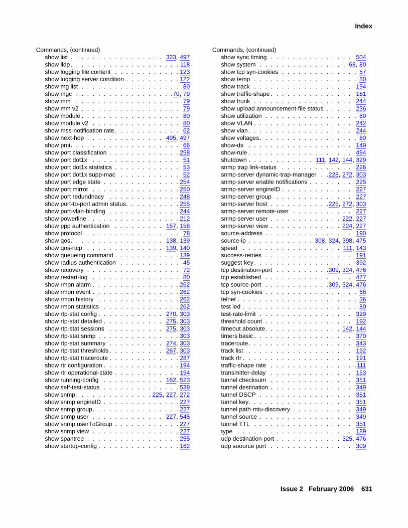
Issue 2 February 2006 631
Index
Commands, (continued)show list . . . . . . . . . . . . . . . . . 323, 497show lldp. . . . . . . . . . . . . . . . . . . . 118show logging file content . . . . . . . . . . . . 123show logging server condition . . . . . . . . . . 122show mg list . . . . . . . . . . . . . . . . . . 80show mgc . . . . . . . . . . . . . . . . . .70, 79show mm . . . . . . . . . . . . . . . . . . . 79show mm v2 . . . . . . . . . . . . . . . . . . 79show module . . . . . . . . . . . . . . . . . . 80show module v2 . . . . . . . . . . . . . . . . 80show mss-notification rate . . . . . . . . . . . . 62show next-hop . . . . . . . . . . . . . . 495, 497show pmi. . . . . . . . . . . . . . . . . . . . 66show port classification . . . . . . . . . . . . . 258show port dot1x . . . . . . . . . . . . . . . . 51show port dot1x statistics . . . . . . . . . . . . 53show port dot1x supp-mac . . . . . . . . . . . 52show port edge state . . . . . . . . . . . . . . 254show port mirror . . . . . . . . . . . . . . . . 250show port redundnacy . . . . . . . . . . . . . 248show port-to-port admin status. . . . . . . . . . 255show port-vlan-binding . . . . . . . . . . . . . 244show powerline . . . . . . . . . . . . . . . . . 212show ppp authentication . . . . . . . . . 157, 158show protocol . . . . . . . . . . . . . . . . . 78show qos. . . . . . . . . . . . . . . . . 138, 139show qos-rtcp . . . . . . . . . . . . . . 139, 140show queueing command . . . . . . . . . . . . 139show radius authentication . . . . . . . . . . . 45show recovery . . . . . . . . . . . . . . . . . 72show restart-log . . . . . . . . . . . . . . . . 80show rmon alarm . . . . . . . . . . . . . . . . 262show rmon event . . . . . . . . . . . . . . . . 262show rmon history . . . . . . . . . . . . . . . 262show rmon statistics . . . . . . . . . . . . . . 262show rtp-stat config . . . . . . . . . . . . 270, 303show rtp-stat detailed . . . . . . . . . . . 275, 303show rtp-stat sessions . . . . . . . . . . 275, 303show rtp-stat snmp . . . . . . . . . . . . . . . 303show rtp-stat summary . . . . . . . . . . 274, 303show rtp-stat thresholds . . . . . . . . . . 267, 303show rtp-stat traceroute . . . . . . . . . . . . . 287show rtr configuration . . . . . . . . . . . . . . 194show rtr operational-state . . . . . . . . . . . . 194show running-config . . . . . . . . . . . 162, 523show self-test-status . . . . . . . . . . . . . . 539show snmp. . . . . . . . . . . . . . 225, 227, 272show snmp engineID . . . . . . . . . . . . . . 227show snmp group. . . . . . . . . . . . . . . . 227show snmp user . . . . . . . . . . . . . 227, 545show snmp userToGroup . . . . . . . . . . . . 227show snmp view . . . . . . . . . . . . . . . . 227show spantree . . . . . . . . . . . . . . . . . 255show startup-config . . . . . . . . . . . . . . . 162
Commands, (continued)show sync timing . . . . . . . . . . . . . . . 504show system . . . . . . . . . . . . . . . . 68, 80show tcp syn-cookies . . . . . . . . . . . . . . 57show temp . . . . . . . . . . . . . . . . . . . 80show track . . . . . . . . . . . . . . . . . . 194show traffic-shape . . . . . . . . . . . . . . . 161show trunk . . . . . . . . . . . . . . . . . . 244show upload announcement-file status . . . . . 236show utilization . . . . . . . . . . . . . . . . . 80show VLAN . . . . . . . . . . . . . . . . . . 242show vlan . . . . . . . . . . . . . . . . . . . 244show voltages. . . . . . . . . . . . . . . . . . 80show-ds . . . . . . . . . . . . . . . . . . . 149show-rule . . . . . . . . . . . . . . . . . . . 494shutdown . . . . . . . . . . . . 111, 142, 144, 329snmp trap link-status . . . . . . . . . . . . . 226snmp-server dynamic-trap-manager . .228, 272, 303snmp-server enable notifications . . . . . . . . 225snmp-server engineID . . . . . . . . . . . . . 227snmp-server group . . . . . . . . . . . . . . 227snmp-server host . . . . . . . . . . .225, 272, 303snmp-server remote-user . . . . . . . . . . . 227snmp-server user . . . . . . . . . . . . . 222, 227snmp-server view . . . . . . . . . . . . . 224, 227source-address . . . . . . . . . . . . . . . . 190source-ip . . . . . . . . . . . . 308, 324, 398, 475speed . . . . . . . . . . . . . . . . . . 111, 143success-retries . . . . . . . . . . . . . . . . 191suggest-key. . . . . . . . . . . . . . . . . . 392tcp destination-port . . . . . . . . . .309, 324, 476tcp established . . . . . . . . . . . . . . . . 477tcp source-port . . . . . . . . . . . .309, 324, 476tcp syn-cookies . . . . . . . . . . . . . . . . . 56telnet . . . . . . . . . . . . . . . . . . . . . . 36test led . . . . . . . . . . . . . . . . . . . . . 80test-rate-limit . . . . . . . . . . . . . . . . . 329threshold count . . . . . . . . . . . . . . . . 192timeout absolute. . . . . . . . . . . . . . 142, 144timers basic . . . . . . . . . . . . . . . . . . 370traceroute. . . . . . . . . . . . . . . . . . . 343track list . . . . . . . . . . . . . . . . . . . 192track rtr . . . . . . . . . . . . . . . . . . . . 191traffic-shape rate . . . . . . . . . . . . . . . .111transmitter-delay . . . . . . . . . . . . . . . 153tunnel checksum . . . . . . . . . . . . . . . 351tunnel destination . . . . . . . . . . . . . . . 349tunnel DSCP . . . . . . . . . . . . . . . . . 351tunnel key. . . . . . . . . . . . . . . . . . . 351tunnel path-mtu-discovery . . . . . . . . . . . 349tunnel source . . . . . . . . . . . . . . . . . 349tunnel TTL . . . . . . . . . . . . . . . . . . 351type . . . . . . . . . . . . . . . . . . . . . 189udp destination-port . . . . . . . . . . . . 325, 476udp soource port . . . . . . . . . . . . . . . 309
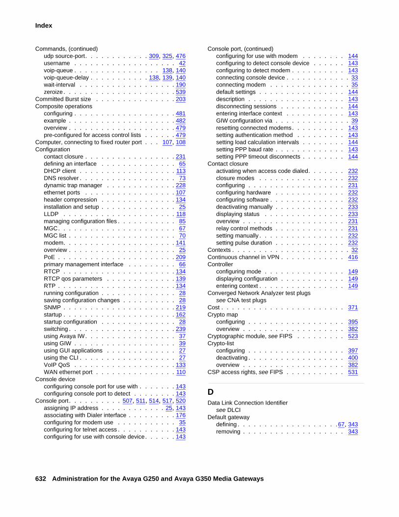
632 Administration for the Avaya G250 and Avaya G350 Media Gateways
Index
Commands, (continued)udp source-port. . . . . . . . . . . . 309, 325, 476username . . . . . . . . . . . . . . . . . . . 42voip-queue . . . . . . . . . . . . . . . . 138, 140voip-queue-delay . . . . . . . . . . . 138, 139, 140wait-interval . . . . . . . . . . . . . . . . . . 190zeroize . . . . . . . . . . . . . . . . . . . . . 539
Committed Burst size . . . . . . . . . . . . . . . 203Composite operations
configuring . . . . . . . . . . . . . . . . . . . 481example . . . . . . . . . . . . . . . . . . . . 482overview . . . . . . . . . . . . . . . . . . . . 479pre-configured for access control lists . . . . . . 479
Computer, connecting to fixed router port . . . 107, 108Configuration
contact closure . . . . . . . . . . . . . . . . . 231defining an interface . . . . . . . . . . . . . . 65DHCP client . . . . . . . . . . . . . . . . . . 113DNS resolver . . . . . . . . . . . . . . . . . . 73dynamic trap manager . . . . . . . . . . . . . 228ethernet ports . . . . . . . . . . . . . . . . . 107header compression . . . . . . . . . . . . . . 134installation and setup . . . . . . . . . . . . . . 25LLDP . . . . . . . . . . . . . . . . . . . . . 118managing configuration files . . . . . . . . . . . 85MGC. . . . . . . . . . . . . . . . . . . . . . 67MGC list . . . . . . . . . . . . . . . . . . . . 70modem. . . . . . . . . . . . . . . . . . . . . 141overview . . . . . . . . . . . . . . . . . . . . 25PoE . . . . . . . . . . . . . . . . . . . . . . 209primary management interface . . . . . . . . . 66RTCP . . . . . . . . . . . . . . . . . . . . . 134RTCP qos parameters . . . . . . . . . . . . . 139RTP . . . . . . . . . . . . . . . . . . . . . . 134running configuration . . . . . . . . . . . . . . 28saving configuration changes . . . . . . . . . . 28SNMP . . . . . . . . . . . . . . . . . . . . . 219startup . . . . . . . . . . . . . . . . . . . . . 162startup configuration . . . . . . . . . . . . . . 28switching . . . . . . . . . . . . . . . . . . . . 239using Avaya IW. . . . . . . . . . . . . . . . . 37using GIW . . . . . . . . . . . . . . . . . . . 39using GUI applications . . . . . . . . . . . . . 27using the CLI . . . . . . . . . . . . . . . . . . 27VoIP QoS . . . . . . . . . . . . . . . . . . . 133WAN ethernet port . . . . . . . . . . . . . . . 110
Console deviceconfiguring console port for use with . . . . . . . 143configuring console port to detect . . . . . . . . 143
Console port. . . . . . . . . . 507, 511, 514, 517, 520assigning IP address . . . . . . . . . . . . 25, 143associating with Dialer interface . . . . . . . . . 176configuring for modem use . . . . . . . . . . . 35configuring for telnet access . . . . . . . . . . . 143configuring for use with console device. . . . . . 143
Console port, (continued)configuring for use with modem . . . . . . . . 144configuring to detect console device . . . . . . 143configuring to detect modem . . . . . . . . . . 143connecting console device . . . . . . . . . . . . 33connecting modem . . . . . . . . . . . . . . . 35default settings . . . . . . . . . . . . . . . . 144description . . . . . . . . . . . . . . . . . . 143disconnecting sessions . . . . . . . . . . . . 144entering interface context . . . . . . . . . . . 143GIW configuration via . . . . . . . . . . . . . . 39resetting connected modems. . . . . . . . . . 143setting authentication method . . . . . . . . . 143setting load calculation intervals . . . . . . . . 144setting PPP baud rate . . . . . . . . . . . . . 143setting PPP timeout disconnects . . . . . . . . 144
Contact closureactivating when access code dialed. . . . . . . 232closure modes . . . . . . . . . . . . . . . . 232configuring . . . . . . . . . . . . . . . . . . 231configuring hardware . . . . . . . . . . . . . 232configuring software . . . . . . . . . . . . . . 232deactivating manually . . . . . . . . . . . . . 233displaying status . . . . . . . . . . . . . . . 233overview . . . . . . . . . . . . . . . . . . . 231relay control methods . . . . . . . . . . . . . 231setting manually . . . . . . . . . . . . . . . . 232setting pulse duration . . . . . . . . . . . . . 232
Contexts . . . . . . . . . . . . . . . . . . . . . . 32Continuous channel in VPN . . . . . . . . . . . . 416Controller
configuring mode . . . . . . . . . . . . . . . 149displaying configuration . . . . . . . . . . . . 149entering context . . . . . . . . . . . . . . . . 149
Converged Network Analyzer test plugssee CNA test plugs
Cost . . . . . . . . . . . . . . . . . . . . . . . 371Crypto map
configuring . . . . . . . . . . . . . . . . . . 395overview . . . . . . . . . . . . . . . . . . . 382
Cryptographic module, see FIPS . . . . . . . . . 523Crypto-list
configuring . . . . . . . . . . . . . . . . . . 397deactivating . . . . . . . . . . . . . . . . . . 400overview . . . . . . . . . . . . . . . . . . . 382
CSP access rights, see FIPS . . . . . . . . . . . 531
DData Link Connection Identifier
see DLCIDefault gateway
defining . . . . . . . . . . . . . . . . . . .67, 343removing . . . . . . . . . . . . . . . . . . . 343
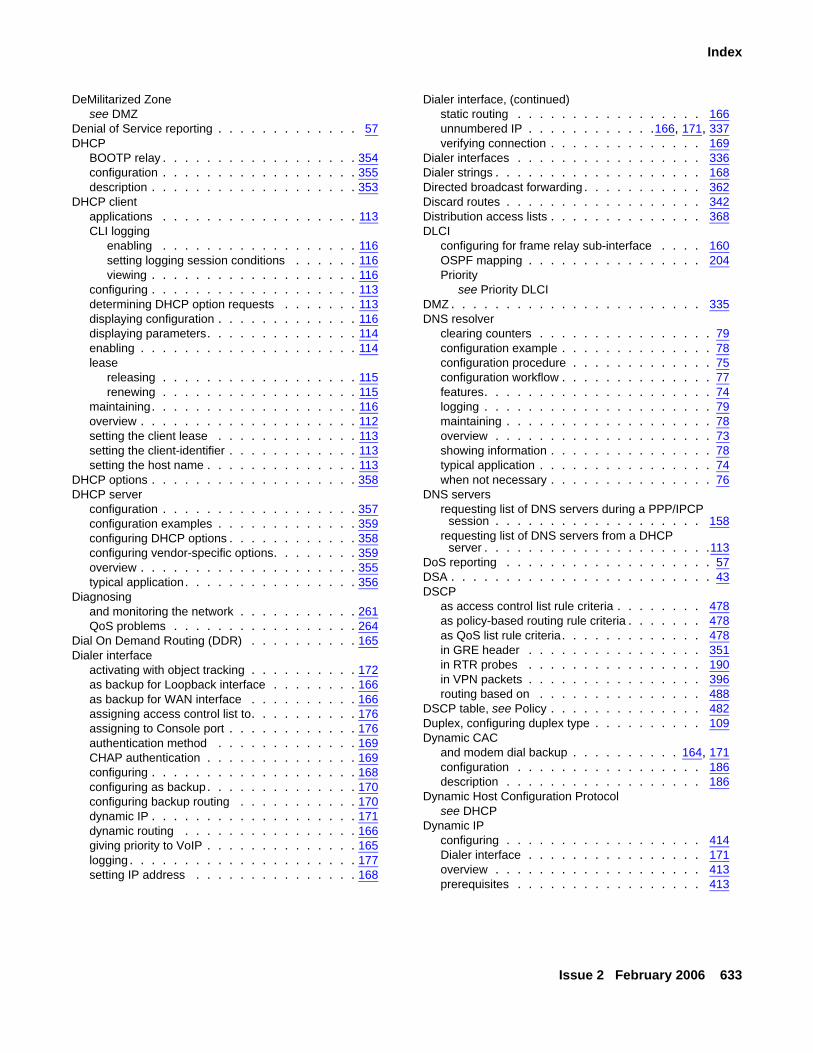
Issue 2 February 2006 633
Index
DeMilitarized Zonesee DMZ
Denial of Service reporting . . . . . . . . . . . . . 57DHCP
BOOTP relay . . . . . . . . . . . . . . . . . . 354configuration . . . . . . . . . . . . . . . . . . 355description . . . . . . . . . . . . . . . . . . . 353
DHCP clientapplications . . . . . . . . . . . . . . . . . . 113CLI logging
enabling . . . . . . . . . . . . . . . . . . 116setting logging session conditions . . . . . . 116viewing . . . . . . . . . . . . . . . . . . . 116
configuring . . . . . . . . . . . . . . . . . . . 113determining DHCP option requests . . . . . . . 113displaying configuration . . . . . . . . . . . . . 116displaying parameters. . . . . . . . . . . . . . 114enabling . . . . . . . . . . . . . . . . . . . . 114lease
releasing . . . . . . . . . . . . . . . . . . 115renewing . . . . . . . . . . . . . . . . . . 115
maintaining. . . . . . . . . . . . . . . . . . . 116overview . . . . . . . . . . . . . . . . . . . . 112setting the client lease . . . . . . . . . . . . . 113setting the client-identifier . . . . . . . . . . . . 113setting the host name . . . . . . . . . . . . . . 113
DHCP options . . . . . . . . . . . . . . . . . . . 358DHCP server
configuration . . . . . . . . . . . . . . . . . . 357configuration examples . . . . . . . . . . . . . 359configuring DHCP options . . . . . . . . . . . . 358configuring vendor-specific options. . . . . . . . 359overview . . . . . . . . . . . . . . . . . . . . 355typical application. . . . . . . . . . . . . . . . 356
Diagnosingand monitoring the network . . . . . . . . . . . 261QoS problems . . . . . . . . . . . . . . . . . 264
Dial On Demand Routing (DDR) . . . . . . . . . . 165Dialer interface
activating with object tracking . . . . . . . . . . 172as backup for Loopback interface . . . . . . . . 166as backup for WAN interface . . . . . . . . . . 166assigning access control list to. . . . . . . . . . 176assigning to Console port . . . . . . . . . . . . 176authentication method . . . . . . . . . . . . . 169CHAP authentication . . . . . . . . . . . . . . 169configuring . . . . . . . . . . . . . . . . . . . 168configuring as backup. . . . . . . . . . . . . . 170configuring backup routing . . . . . . . . . . . 170dynamic IP . . . . . . . . . . . . . . . . . . . 171dynamic routing . . . . . . . . . . . . . . . . 166giving priority to VoIP . . . . . . . . . . . . . . 165logging . . . . . . . . . . . . . . . . . . . . . 177setting IP address . . . . . . . . . . . . . . . 168
Dialer interface, (continued)static routing . . . . . . . . . . . . . . . . . 166unnumbered IP . . . . . . . . . . . .166, 171, 337verifying connection . . . . . . . . . . . . . . 169
Dialer interfaces . . . . . . . . . . . . . . . . . 336Dialer strings . . . . . . . . . . . . . . . . . . . 168Directed broadcast forwarding . . . . . . . . . . . 362Discard routes . . . . . . . . . . . . . . . . . . 342Distribution access lists . . . . . . . . . . . . . . 368DLCI
configuring for frame relay sub-interface . . . . 160OSPF mapping . . . . . . . . . . . . . . . . 204Priority
see Priority DLCIDMZ . . . . . . . . . . . . . . . . . . . . . . . 335DNS resolver
clearing counters . . . . . . . . . . . . . . . . 79configuration example . . . . . . . . . . . . . . 78configuration procedure . . . . . . . . . . . . . 75configuration workflow . . . . . . . . . . . . . . 77features. . . . . . . . . . . . . . . . . . . . . 74logging . . . . . . . . . . . . . . . . . . . . . 79maintaining . . . . . . . . . . . . . . . . . . . 78overview . . . . . . . . . . . . . . . . . . . . 73showing information . . . . . . . . . . . . . . . 78typical application . . . . . . . . . . . . . . . . 74when not necessary . . . . . . . . . . . . . . . 76
DNS serversrequesting list of DNS servers during a PPP/IPCP
session . . . . . . . . . . . . . . . . . . . 158requesting list of DNS servers from a DHCP
server . . . . . . . . . . . . . . . . . . . . .113DoS reporting . . . . . . . . . . . . . . . . . . . 57DSA . . . . . . . . . . . . . . . . . . . . . . . . 43DSCP
as access control list rule criteria . . . . . . . . 478as policy-based routing rule criteria . . . . . . . 478as QoS list rule criteria. . . . . . . . . . . . . 478in GRE header . . . . . . . . . . . . . . . . 351in RTR probes . . . . . . . . . . . . . . . . 190in VPN packets . . . . . . . . . . . . . . . . 396routing based on . . . . . . . . . . . . . . . 488
DSCP table, see Policy . . . . . . . . . . . . . . 482Duplex, configuring duplex type . . . . . . . . . . 109Dynamic CAC
and modem dial backup . . . . . . . . . . 164, 171configuration . . . . . . . . . . . . . . . . . 186description . . . . . . . . . . . . . . . . . . 186
Dynamic Host Configuration Protocolsee DHCP
Dynamic IPconfiguring . . . . . . . . . . . . . . . . . . 414Dialer interface . . . . . . . . . . . . . . . . 171overview . . . . . . . . . . . . . . . . . . . 413prerequisites . . . . . . . . . . . . . . . . . 413
634 Administration for the Avaya G250 and Avaya G350 Media Gateways
Index
Dynamic routesdeleting . . . . . . . . . . . . . . . . . . . . 343redestributing. . . . . . . . . . . . . . . . . . 373
EE1/T1 lines
connecting to WAN media module . . . . . . . . 145default settings . . . . . . . . . . . . . . . . . 152
E1/T1 ports . . . . . . . . . . . . . . . . . . . . 149EAP. . . . . . . . . . . . . . . . . . . . . . . . 46EAP over RADIUS . . . . . . . . . . . . . . . . . 46EAPOL . . . . . . . . . . . . . . . . . . . . . . 46ECMP. . . . . . . . . . . . . . . . . . . . . . . 371Emergency Transfer Relay
see ETREmergency Transfer Relay, see ETRError states, see FIPS . . . . . . . . . . . . . . . 556ETH LAN port . . . . . . . . . 506, 510, 513, 516, 520ETH WAN port. . . . . . . . . . . . . . . . . . . 520Ethernet ports
configuration . . . . . . . . . . . . . . . . . . 107configuring duplex type . . . . . . . . . . . . . 109configuring link negotiation protocol . . . . . . . 109configuring switch port . . . . . . . . . . . . . 108connecting devices to . . . . . . . . . . . 107, 108list of. . . . . . . . . . . . . . . . . . . 107, 108port redundancy . . . . . . . . . . . . . . . . 247setting flowcontrol advertisements . . . . . . . . 109WAN Ethernet port
see WAN Ethernet portETR
deactivating . . . . . . . . . . . . . . . . . . 216description . . . . . . . . . . . . . . . . . . . 215displaying status . . . . . . . . . . . . . . . . 217in SLS mode . . . . . . . . . . . . . . . . . . 87LED . . . . . . . . . . . . . . . . . . . . . . 215manual activation . . . . . . . . . . . . . . . . 216setting state . . . . . . . . . . . . . . . . . . 216trunk-to-port latchings in G250. . . . . . . . . . 215
Excess Burst size . . . . . . . . . . . . . . . . . 203Extensible Authentication Protocol . . . . . . . . . 46
FFair VoIP queue . . . . . . . . . . . . . . . . . . 140Fast Ethernet interface
checking status . . . . . . . . . . . . . . . . . 183configuring PPPoE . . . . . . . . . . . . . . . 155described . . . . . . . . . . . . . . . . . . . 335dynamic bandwidth reporting . . . . . . . . . . 186ICMP keepalive. . . . . . . . . . . . . . . . . 183
Fast Ethernet port . . . . . . . . . . . . . . . . 184auto-negotiation . . . . . . . . . . . . . . . . .111configuring duplex type . . . . . . . . . . . . . 111configuring interface . . . . . . . . . . . . . . .110configuring port speed . . . . . . . . . . . . . . 111firewall connected . . . . . . . . . . . . . . . 335VPN connected . . . . . . . . . . . . . . . . 335
Federal Information Processing Standard, see FIPSFile transfer, see FTP or TFTP . . . . . . . . . . . 81FIPS
adding next-hops . . . . . . . . . . . . . . . 341administration procedures . . . . . . . . . . . 538approved alogorithms . . . . . . . . . . . . . 523assumption of roles . . . . . . . . . . . . . . 525assumptions concerning user behavior . . . . . 527CLI commands . . . . . . . . . . . . . . . . 539critical security paramets. . . . . . . . . . . . 528cryptographic alogrithm tests . . . . . . . . . . 536cryptographic module . . . . . . . . . . . . . 523CSP access rights . . . . . . . . . . . . . . . 531disabling modem dial backup. . . . . . . . . . 172entering fips mode. . . . . . . . . . . . . . . 539error states . . . . . . . . . . . . . . . . . . 556failure scenarios. . . . . . . . . . . . . . . . 555FIPS-compliant mode . . . . . . . . . . . . . 537gateway software integrity test . . . . . . . . . 536next-hops static routes. . . . . . . . . . . . . 340non-approved algorithms. . . . . . . . . . . . 523non-FIPS mode . . . . . . . . . . . . . . . . 524operational environment . . . . . . . . . . . . 525overview . . . . . . . . . . . . . . . . . . . 505password guidelines . . . . . . . . . . . . . . 537power-up self-test order . . . . . . . . . . . . 555prerequisites . . . . . . . . . . . . . . . . . 538private keys . . . . . . . . . . . . . . . . . . 528public keys . . . . . . . . . . . . . . . . . . 530recovering from an error state . . . . . . . . . 557repair actions . . . . . . . . . . . . . . . . . 555security level . . . . . . . . . . . . . . . . . 525security rules . . . . . . . . . . . . . . . . . 535verifying media mode . . . . . . . . . . . . . 523
Firewall . . . . . . . . . . . . . . . . . . . . . 335Firmware
firmware bank defaults. . . . . . . . . . . . . . 82firmware banks . . . . . . . . . . . . . . . . . 29load with ASB button . . . . . . . . . . . . . . 82managing firmware banks . . . . . . . . . . . . 82redundancy . . . . . . . . . . . . . . . . . . . 82upgrade overview . . . . . . . . . . . . . . . . 82upgrading with the CLI . . . . . . . . . . . . . . 83version control . . . . . . . . . . . . . . . . . 29version management . . . . . . . . . . . . . . 81
Fixed analog trunk port . . . . . . . . . . . . . . 215
Issue 2 February 2006 635
Index
Fixed portsCCA . . . . . . . . . . . . 506, 510, 513, 517, 520CONSOLE . . . . . . . . . . . . . . . . . . . 520Console . . . . . . . . . . . . .507, 511, 514, 517ETH LAN. . . . . . . . . . 506, 510, 513, 516, 520ETH WAN . . . . . . . . . . . . . . . . . . . 520LINE 2 . . . . . . . . . . . 507, 510, 513, 517, 520LINE1 . . . . . . . . . . . 507, 510, 513, 517, 520TRUNK . . . . . . . . . . . . . . . . . . . . 520USB . . . . . . . . . . . . 507, 511, 514, 517, 521
Flowcontrol advertisement . . . . . . . . . . . . . 109Fragmentation
as map class parameter. . . . . . . . . . . . . 203configuration . . . . . . . . . . . . . . . . . . 378description . . . . . . . . . . . . . . . . . . . 377GRE tunneling . . . . . . . . . . . . . . . . . 348reassembly. . . . . . . . . . . . . . . . . . . 378
Frame relay . . . . . . . . . . . . . . . . . . . . 146configuring sub-interfaces . . . . . . . . . . . . 159displaying configuration . . . . . . . . . . . . . 161enabling traffic shaping . . . . . . . . . . . . . 203
Frame relay encapsulationconfiguring on WAN port . . . . . . . . . . . . 159down status . . . . . . . . . . . . . . . . . . 163encapsulation types. . . . . . . . . . . . . . . 159establishing Layer 3 interface . . . . . . . . . . 341IETF . . . . . . . . . . . . . . . . . . . . . . 159illustration . . . . . . . . . . . . . . . . . . . 147non-IETF. . . . . . . . . . . . . . . . . . . . 159supported features . . . . . . . . . . . . . . . 203supported on Serial interfaces . . . . . . . . . . 336supported on serial interfaces . . . . . . . . . . 147
Frame relay traffic shapingconfiguring within map classes . . . . . . . . . 203description . . . . . . . . . . . . . . . . . . . 203displaying configuration . . . . . . . . . . . . . 161enabling . . . . . . . . . . . . . . . . . . . . 203
FRF.12 fragmentationconfiguring within map classes . . . . . . . . . 203description . . . . . . . . . . . . . . . . . . . 203
FTP. . . . . . . . . . . . . . . . . . . . . . . . 81
GG250
analog model, see G250-AnalogBRI model, see G250-BRIDCP model, see G250-DCPDS1 model, see G250-DS1features . . . . . . . . . . . . . . . . . . . . 21interfaces . . . . . . . . . . . . . . 506, 512, 516media modules . . . . . . . . . . . . . . . . . 22target environment . . . . . . . . . . . . . . . 21
G250 front panel . . . . . . . . . . . . . 506, 512, 516G250-BRI . . . . . . . . . . . . . . . . . . . . . 22
G250-DCP . . . . . . . . . . . . . . . . . . . . . 22G250-DS1 . . . . . . . . . . . . . . . . . . . . . 22G350
features. . . . . . . . . . . . . . . . . . . . . 21interfaces . . . . . . . . . . . . . . . . . . . 519media modules . . . . . . . . . . . . . . . . . 21target environment . . . . . . . . . . . . . . . 21
G350 front panel . . . . . . . . . . . . . . . . . 519General context . . . . . . . . . . . . . . . . . . 32Generic Routing Encapsulation, see GRE tunnelingGigabit Ethernet port
location . . . . . . . . . . . . . . . . . . 107, 108port redunancy . . . . . . . . . . . . . . . . 247
GIWaccessing. . . . . . . . . . . . . . . . . . . . 38configuration using . . . . . . . . . . . . . . . 39description . . . . . . . . . . . . . . . . . . . 38installation on laptop. . . . . . . . . . . . . . . 39
GRE tunnelingadding checksum . . . . . . . . . . . . . . . 351adding ID keys . . . . . . . . . . . . . . . . 351applications . . . . . . . . . . . . . . . . . . 344as next hop . . . . . . . . . . . . . . . . . . 495assigning DSCP. . . . . . . . . . . . . . . . 351assigning TTL . . . . . . . . . . . . . . . . . 351checking tunnel status . . . . . . . . . . . 348, 350compared to VPN . . . . . . . . . . . . . . . 344configuring tunnel . . . . . . . . . . . . . . . 349displaying tunnel information . . . . . . . . . . 351dynamic bandwidth reporting . . . . . . . . . . 186dynamic MTU discovery . . . . . . . . . . . . 348optional features . . . . . . . . . . . . . . . 348overview . . . . . . . . . . . . . . . . . 335, 344preventing recursive routing . . . . . . . . . . 345routing packets to tunnel . . . . . . . . . . . . 345
GUI tools, configuring the system with . . . . . . . . 27
HHeader compression
clearing rtp header compression statistics. . . . 138clearing tcp header compression statistics . . . 138decompression . . . . . . . . . . . . . . . . 134IPCH method - RTP and TCP header compression
configuring. . . . . . . . . . . . . . . . . 135configuring UDP ports range . . . . . . . . 136disabling. . . . . . . . . . . . . . . . . . 137enabling . . . . . . . . . . . . . . . . . . 136overview. . . . . . . . . . . . . . . . . . 134
methods . . . . . . . . . . . . . . . . . . . 134overview . . . . . . . . . . . . . . . . . . . 134showing rtp header compression statistics . . . 138showing tcp header compression statistics . . . 138supported methods per interface type. . . . . . 135transmission rate . . . . . . . . . . . . . . . 134
636 Administration for the Avaya G250 and Avaya G350 Media Gateways
Index
Header compressione, (continued)Van Jacobson Method - TCP header compression
configuring . . . . . . . . . . . . . . . . . 137disabling . . . . . . . . . . . . . . . . . . 137enabling . . . . . . . . . . . . . . . . . . 137overview . . . . . . . . . . . . . . . . . . 134
Hello packets . . . . . . . . . . . . . . . . . . . 372Help
CLI . . . . . . . . . . . . . . . . . . . . . . 32commands . . . . . . . . . . . . . . . . . . . 32
High Preference static routes . . . . . . . . . . . . 340
IICC-VLAN. . . . . . . . . . . . . . . . . . . . . 243ICMP errors . . . . . . . . . . . . . . . . . . . . 366ICMP keepalive . . . . . . . . . . . . . . . . . . 183
and policy-based routing . . . . . . . . . . . . 487IGAR . . . . . . . . . . . . . . . . . . 164, 171, 186IKE
phase 1 . . . . . . . . . . . . . . . . . . . . 379phase 2 . . . . . . . . . . . . . . . . . . . . 379
Ingress Access Control List . . . . . . . . . . . . . 487Ingress QoS List . . . . . . . . . . . . . . . . . . 487Interfaces
adjusting bandwidth. . . . . . . . . . . . . . . 371administrative status . . . . . . . . . . . . . . 111applying PBR lists . . . . . . . . . . . . . . . 492assigning Cost . . . . . . . . . . . . . . . . . 371assigning IP addresses . . . . . . . . . . . . . 65authentication . . . . . . . . . . . . . . . . . 369backup. . . . . . . . . . . . . . . . . . . . . 111configuration . . . . . . . . . . . . . . . 334, 336configuration examples . . . . . . . . . . . . . 337defining . . . . . . . . . . . . . . . . . . . . 65Dialer . . . . . . . . . . . . . . . . . . . . . 336disabling . . . . . . . . . . . . . . . . . . . . 340displaying information . . . . . . . . . . . . . . 162displaying status . . . . . . . . . . . . . . . . 326duplex type. . . . . . . . . . . . . . . . . . . 111dynamic bandwidth reporting . . . . . . . . . . 186FastEthernet . . . . . . . . . . . . . . . . . . 335frame relay . . . . . . . . . . . . . . . . . . . 159GRE tunnel, see GRE tunnelingIP
see IP interfacesLayer 2. . . . . . . . . . . . . . . . . . 335, 340Layer 3. . . . . . . . . . . . . . . . . . . . . 341logical . . . . . . . . . . . . . . . . . . . . . 336Loopback . . . . . . . . . . . . . . 335, 487, 492metrics . . . . . . . . . . . . . . . . . . . . . 372network type . . . . . . . . . . . . . . . . . . 372physical . . . . . . . . . . . . . . . . . . . . 335priority . . . . . . . . . . . . . . . . . . . . . 372Serial . . . . . . . . . . . . . . . . . . . . . 336
Interfaces, (continued)serial
see Serial interfacessetting administrative state . . . . . . . . . . . 336setting load calculation intervals . . . . . . . . . 65speed . . . . . . . . . . . . . . . . . . . . .111switching . . . . . . . . . . . . . . . . . 335, 336testing configuration . . . . . . . . . . . . . . 161types . . . . . . . . . . . . . . . . . . . . . 336unnumbered IP . . . . . . . . . . . . . . . . 337updating broadcast address . . . . . . . . . . 336USP WAN . . . . . . . . . . . . . . . . . . 335virtual. . . . . . . . . . . . . . . . . . . 147, 335WAN . . . . . . . . . . . . . . . . . . . . . 335
Inter-Gateway Alternate Routing, see IGARInternet Key Exchange (IKE) . . . . . . . . . . . 379IP address
assigning to console port. . . . . . . . . . . . . 25assigning to USB port . . . . . . . . . . . . . . 26defining . . . . . . . . . . . . . . . . . . . . 336obtaining via DHCP . . . . . . . . . . . . . . .113obtaining via PPP/IPCP negotiation. . . . . . . 157storing in ARP table . . . . . . . . . . . . . . 363
ip domain timeout. . . . . . . . . . . . . . . . . . 76IP interfaces . . . . . . . . . . . . . . . . . . . 336IP interfaces, see InterfacesIP Security, see VPNIP unnumbered interface, see Unnumbered IP interfaceISAKMP
peer-group configuration . . . . . . . . . . . . 394policies . . . . . . . . . . . . . . . . . . . . 388VPN peer configuration . . . . . . . . . . . . 391
Kkeepalive
configuring on PPP WAN line . . . . . . . . . 155keepalive ICMP, see ICMP keepaliveKeepalive, GRE tunnel . . . . . . . . . . . . . . 348keepalive-track
configuring in VPN. . . . . . . . . . . . . . . 393configuring on PPPoE interface . . . . . . . . 158
LLAN . . . . . . . . . . . . . . . . . . . . . . . 335Layer 2 interfaces . . . . . . . . . . . . . . . . 340Layer 2 logical interfaces . . . . . . . . . . . . . 336Layer 2 virtual interfaces . . . . . . . . . . . . . 335Layer 3 interfaces . . . . . . . . . . . . . . . . 341LEDs, ETR. . . . . . . . . . . . . . . . . . . . 215LINE 1 port. . . . . . . . . . .507, 510, 513, 517, 520LINE 2 port. . . . . . . . . . .507, 510, 513, 517, 520Link Layer Discovery Proticol, see LLDP . . . . . . .116Link-state algorithm. . . . . . . . . . . . . . . . 370
Issue 2 February 2006 637
Index
LLDP802.1 TLVs (optional) . . . . . . . . . . . . . . 117configuration . . . . . . . . . . . . . . . . . . 118enabling . . . . . . . . . . . . . . . . . . . . 118mandatory TLVs . . . . . . . . . . . . . . . . 117optional TLVs. . . . . . . . . . . . . . . . . . 117overview . . . . . . . . . . . . . . . . . . . . 116setting additional TLVs . . . . . . . . . . . . . 118setting port status. . . . . . . . . . . . . . . . 118supported ports (G250) . . . . . . . . . . . . . 118supported ports (G350) . . . . . . . . . . . . . 118supported TLVs . . . . . . . . . . . . . . . . 117verify advertisements . . . . . . . . . . . . . . 118
LMI parameters . . . . . . . . . . . . . . . . . . 159Load balancing
ECMP . . . . . . . . . . . . . . . . . . . . . 371VRRP . . . . . . . . . . . . . . . . . . . . . 374
Local Management Interfacesee LMI parameters
Log filesee Logging
Loggingconfiguring log file . . . . . . . . . . . . . . . 123configuring session log . . . . . . . . . . . . . 124configuring Syslog server . . . . . . . . . . . . 120default severity levels . . . . . . . . . . . . . . 127defining filters . . . . . . . . . . . . . . . . . 126deleting log file . . . . . . . . . . . . . . . . . 123deleting Syslog server . . . . . . . . . . . . . 121Dialer interface . . . . . . . . . . . . . . . . . 177disabling log file . . . . . . . . . . . . . . . . 123disabling session log . . . . . . . . . . . . . . 125disabling Syslog server . . . . . . . . . . . . . 121displaying log file contents. . . . . . . . . . . . 123displaying Syslog server status . . . . . . . . . 122enabling log file . . . . . . . . . . . . . . . . . 123enabling session log . . . . . . . . . . . . . . 124enabling Syslog server . . . . . . . . . . . . . 120examples . . . . . . . . . . . . . . . . . . . 130filtering by application . . . . . . . . . . . . . . 128introduction. . . . . . . . . . . . . . . . . . . 119limiting Syslog access. . . . . . . . . . . . . . 121log file . . . . . . . . . . . . . . . . . . . . . 119log file example. . . . . . . . . . . . . . . . . 130log file filter contents . . . . . . . . . . . . . . 126log file message format . . . . . . . . . . . . . 124modem dial backup . . . . . . . . . . . . . . . 177object trackers . . . . . . . . . . . . . . . . . 194object tracking . . . . . . . . . . . . . . . . . 194overview . . . . . . . . . . . . . . . . . . . . 119RTR . . . . . . . . . . . . . . . . . . . . . . 194saving settings . . . . . . . . . . . . . . . . . 120session log . . . . . . . . . . . . . . . . 119, 125session log example . . . . . . . . . . . . . . 131session log message format . . . . . . . . . . . 125
Logging, (continued)setting filters . . . . . . . . . . . . . . . . . 126severity levels . . . . . . . . . . . . . . . . . 127sinks . . . . . . . . . . . . . . . . . . . . . .119specifying Syslog output facility. . . . . . . . . 120Syslog default settings . . . . . . . . . . . . . 122Syslog server . . . . . . . . . . . . . . . . . .119Syslog server example. . . . . . . . . . . . . 130Syslog server message format . . . . . . . . . 122VPN . . . . . . . . . . . . . . . . . . . . . 405
Logging session, see LoggingLogical interfaces. . . . . . . . . . . . . . . . . 336Loopback interface . . . . . . . . . 166, 335, 487, 492Loops
defined . . . . . . . . . . . . . . . . . . . . 252preventing in GRE tunneling . . . . . . . . . . 345preventing in RIP . . . . . . . . . . . . . . . 367
Low preference static routes . . . . . . . . . . . 340
MMAC addresses, storing in ARP table . . . . . . . 363Managed Security Services, see MSSMap classes
applying to all configured Permanent Virtual Channels . . . . . . . . . . . . . . . . . . 203
default . . . . . . . . . . . . . . . . . . . . 203number that can be configured . . . . . . . . . 203parameters . . . . . . . . . . . . . . . . . . 203
Media modulesMM314 . . . . . . . . . . . . . . . . . . .46, 108MM316 . . . . . . . . . . . . . . . . . . .46, 108MM340 . . . . . . . . . . . . . . . . . . 149, 335MM342 . . . . . . . . . . . . . . . .149, 153, 335USP WAN, see MM342 media moduleWAN . . . . . . . . . . . . . . . . . . . . . 149
Metrics. . . . . . . . . . . . . . . . . . . . . . 374MGC
accessing. . . . . . . . . . . . . . . . . . . . 40accessing the registered MGC . . . . . . . . . . 72auto fallback to primary . . . . . . . . . . . . . 69changing the list . . . . . . . . . . . . . . . . . 71checking connectivity with . . . . . . . . . . . 166clearing the lost . . . . . . . . . . . . . . . . . 71configuring . . . . . . . . . . . . . . . . . . . 67displaying the list . . . . . . . . . . . . . . . . 70monitoring the ICC . . . . . . . . . . . . . . . 73monitoring the LSP . . . . . . . . . . . . . . . 73overview . . . . . . . . . . . . . . . . . . . . 68reporting bandwidth to . . . . . . . . . . . . . 186running Avaya Communication Manager . . . . . 40setting reset times . . . . . . . . . . . . . . . . 71setting the list . . . . . . . . . . . . . . . . . . 70supported media servers. . . . . . . . . . . . . 68
638 Administration for the Avaya G250 and Avaya G350 Media Gateways
Index
MGC listSLS entry . . . . . . . . . . . . . . . . . . . 90
MM314 media module802.1x protocol . . . . . . . . . . . . . . . . . 46Ethernet ports . . . . . . . . . . . . . . . . . 108
MM316 media module802.1x protocol . . . . . . . . . . . . . . . . . 46Ethernet ports . . . . . . . . . . . . . . . . . 108
MM340 media moduleconfiguring . . . . . . . . . . . . . . . . . . . 149E1/T1 WAN interface . . . . . . . . . . . . . . 335
MM342 media moduleconfiguring . . . . . . . . . . . . . . . . . . . 153USP WAN interface . . . . . . . . . . . . . . . 335
Modemconfiguring . . . . . . . . . . . . . . . . . . . 141configuring console port for use with . . . . . . . 144configuring console port to detect . . . . . . . . 143configuring type on console port . . . . . . . . . 143connecting to console port. . . . . . . . . . . . 35connecting to S8300 Media Server. . . . . . . . 36connecting to USB port . . . . . . . . . . . . . 34connecting via USB modem . . . . . . . . . . . 36dial backup, see Modem dial backupdisplaying USB modem status . . . . . . . . . . 142serial. . . . . . . . . . . . . . . . . . . . . . 143USB . . . . . . . . . . . . . . . . . . . . . . 141
Modem dial backupactivating with object tracking . . . . . . . . . . 172and dynamic CAC . . . . . . . . . . . . 164, 171as backup interface . . . . . . . . . . . . . . . 165authentication method . . . . . . . . . . . . . 169bandwidth available for . . . . . . . . . . . . . 165CHAP authentication . . . . . . . . . . . . . . 169configuration . . . . . . . . . . . . . . . . . . 168configuration example. . . . . . . . . . . . . . 172configuring backup routing . . . . . . . . . . . 170entering dialer strings . . . . . . . . . . . . . . 168feature interactions . . . . . . . . . . . . . . . 171FIPS and. . . . . . . . . . . . . . . . . . . . 172logging . . . . . . . . . . . . . . . . . . . . . 177overview . . . . . . . . . . . . . . . . . . . . 164policy lists and . . . . . . . . . . . . . . . . . 165prerequisites . . . . . . . . . . . . . . . . . . 167RAS configuration . . . . . . . . . . . . . . . 167typical installations . . . . . . . . . . . . . . . 167using VPN . . . . . . . . . . . . . . . . . . . 165Weighted Fair Queuing and . . . . . . . . . . . 165
Monitoring applicationsCNA test plugs . . . . . . . . . . . . . . . . . 327configuring . . . . . . . . . . . . . . . . . . . 261RMON . . . . . . . . . . . . . . . . . . 261, 303RTP statistics. . . . . . . . . . . . . . . . . . 264
MSSCLI commands . . . . . . . . . . . . . . . . . 62configuring . . . . . . . . . . . . . . . . . . . 58example . . . . . . . . . . . . . . . . . . . . 63Overview . . . . . . . . . . . . . . . . . . . . 57predefined DoS classes . . . . . . . . . . . . . 60reporting mechanism . . . . . . . . . . . . . . 57user-defined DoS classes . . . . . . . . . . . . 61
Multipoint topology support . . . . . . . . . . . . 148
NNAT Traversal
configuring . . . . . . . . . . . . . . . . . . 401overview . . . . . . . . . . . . . . . . . . . 401
Nested tunneling . . . . . . . . . . . . . . . . . 345NetBIOS . . . . . . . . . . . . . . . . . . . . . 362Network monitoring
applications . . . . . . . . . . . . . . . . . . 261using RMON . . . . . . . . . . . . . . . . . 261using RTP statistics application. . . . . . . . . 264
Next hop listsapplying to policy-based routing rules . . . . . . 494backup routes . . . . . . . . . . . . . . . . . 489editing . . . . . . . . . . . . . . . . . . . . 495entries . . . . . . . . . . . . . . . . . . . . 495overview . . . . . . . . . . . . . . . . . . . 494
Next-hops, see FIPS . . . . . . . . . . . . . . . 340Non-FIPS, see FIPS . . . . . . . . . . . . . . . 524
OObject tracking
activating Dialer interface . . . . . . . . . . . 172applying to DHCP client . . . . . . . . . . . . .114applying to PBR next-hops . . . . . . . . . . . 491applying to static routes . . . . . . . . . . . . 340backup for the Fast Ethernet interface . . . . . 198configuration . . . . . . . . . . . . . . . . . 188configuration examples . . . . . . . . . . . . 195configuration workflow . . . . . . . . . . . . . 192enabling logging. . . . . . . . . . . . . . . . 194interface backup via policy-based routing . . . . 201maintenance . . . . . . . . . . . . . . . . . 194object tracker configuration . . . . . . . . . . 191overview . . . . . . . . . . . . . . . . . . . 188RTR configuration . . . . . . . . . . . . . . . 189showing configuration . . . . . . . . . . . . . 194showing routes with tracking . . . . . . . . . . 343tracking a single device . . . . . . . . . . . . 195tracking multiple devices . . . . . . . . . . . . 196typical applications . . . . . . . . . . . . . . 197verifying MGC connectivity . . . . . . . . . . . 166viewing log messages . . . . . . . . . . . . . 194VPN failover . . . . . . . . . . . . . . . . . 198
Issue 2 February 2006 639
Index
Open Shortest Path First protocolsee OSPF
OSPFadvertising static routes . . . . . . . . . . . . . 340compared to RIP . . . . . . . . . . . . . 366, 370configuration . . . . . . . . . . . . . . . . . . 372default metric . . . . . . . . . . . . . . . . . . 374description . . . . . . . . . . . . . . . . . . . 370displaying information . . . . . . . . . . . . . . 372DLCI mapping . . . . . . . . . . . . . . . . . 204dynamic Cost. . . . . . . . . . . . . . . . . . 371enabling on network . . . . . . . . . . . . . . 372enabling on system . . . . . . . . . . . . . . . 372interface authentication password . . . . . . . . 372limitations . . . . . . . . . . . . . . . . . . . 371metrics . . . . . . . . . . . . . . . . . . . . . 372modem dial backup and . . . . . . . . . . . . . 167priority . . . . . . . . . . . . . . . . . . . . . 372redistributing routing information . . . . . . . . . 372suppressing updates . . . . . . . . . . . . . . 372using with RIP . . . . . . . . . . . . . . . . . 373
OSPF Autonomous System Boundary Router . . . . 371
PPacket sniffing
analyzing capture file . . . . . . . . . . . . . . 319analyzing captured packets . . . . . . . . . . . 316applying a capture-list . . . . . . . . . . . . . . 313applying rules to an address range. . . . . . . . 308applying rules to packets with specified
DSCP values . . . . . . . . . . . . . . . . . 308applying rules to packets with specified ip
protocols . . . . . . . . . . . . . . . . . . . 308capture list examples . . . . . . . . . . . . . . 312clearing the capture buffer. . . . . . . . . . . . 314CLI commands . . . . . . . . . . . . . . . . . 321configuring . . . . . . . . . . . . . . . . . . . 305creating capture-list . . . . . . . . . . . . . . . 306defining rule criteria . . . . . . . . . . . . . . . 306disabling . . . . . . . . . . . . . . . . . . . . 305enabling . . . . . . . . . . . . . . . . . . . . 305enabling the service. . . . . . . . . . . . . . . 315excepting protocols from rules . . . . . . . . . . 308excluding ICMP type and code . . . . . . . . . 311indentifying the interface . . . . . . . . . . . . 320information, viewing. . . . . . . . . . . . . . . 316introduction. . . . . . . . . . . . . . . . . . . 303overview . . . . . . . . . . . . . . . . . . . . 303packets captured . . . . . . . . . . . . . . . . 304reducing the size of the capture file . . . . . . . 315rule criteria commands . . . . . . . . . . . . . 307scp file upload limit . . . . . . . . . . . . . . . 318service, starting. . . . . . . . . . . . . . . . . 315service, stopping . . . . . . . . . . . . . . . . 316
Packet sniffing, (continued)setting buffers . . . . . . . . . . . . . . . . . 314setting capture list context . . . . . . . . . . . 306setting capture list parameters . . . . . . . . . 306setting max frame size . . . . . . . . . . . . . 314settings . . . . . . . . . . . . . . . . . . . . 314simulating packets. . . . . . . . . . . . . . . 321specifiying ICMP type and code . . . . . . . . .311specifying bugger size . . . . . . . . . . . . . 314specifying capture actions . . . . . . . . . . . 306specifying interfaces . . . . . . . . . . . . . . 305streams that can be captured . . . . . . . . . 304streams that cannot be captured . . . . . . . . 304streams with conditional capture requirements . 304uploading capture file . . . . . . . . . . . . . 317uploading capture files to remote servers . . . . 318uploading capture files to the S8300 . . . . . . 318viewing the capture-list . . . . . . . . . . . . 313viewing, captured packet hex dump. . . . . . . 316
Packets, simulating, see Policy . . . . . . . . . . 485Password Authentication Protocol . . . . . . . 141, 143Password guidelines, see FIPS . . . . . . . . . . 537Passwords
changing . . . . . . . . . . . . . . . . . . . . 42managing . . . . . . . . . . . . . . . . . . . . 42overview . . . . . . . . . . . . . . . . . . . . 41recovery password . . . . . . . . . . . . . . . 54
PBR listsattaching to interface . . . . . . . . . . . . . 492attaching to Loopback interface . . . . . . 487, 492creating. . . . . . . . . . . . . . . . . . . . 490deleting . . . . . . . . . . . . . . . . . . . . 496editing . . . . . . . . . . . . . . . . . . . . 490editing rules. . . . . . . . . . . . . . . . . . 494modifying . . . . . . . . . . . . . . . . . . . 496name . . . . . . . . . . . . . . . . . . . . . 490rule criteria . . . . . . . . . . . . . . . . . . 493rules . . . . . . . . . . . . . . . . . . . 490, 493
Permanent routes . . . . . . . . . . . . . . . . 342PIM
accessing. . . . . . . . . . . . . . . . . . . . 40description . . . . . . . . . . . . . . . . . . . 40SLS configuration . . . . . . . . . . . . . . . . 94
Ping . . . . . . . . . . . . . . . . . . . . . . . 162PMI
configuration . . . . . . . . . . . . . . . . . . 66entering the interface context. . . . . . . . . . . 66explanation . . . . . . . . . . . . . . . . . . . 66resetting the interface . . . . . . . . . . . . . . 66setting location information. . . . . . . . . . . . 67setting system contact information . . . . . . . . 67setting the system name . . . . . . . . . . . . . 67showing the PMI . . . . . . . . . . . . . . . . 66
640 Administration for the Avaya G250 and Avaya G350 Media Gateways
Index
PoEadding and removing devices . . . . . . . . . . 211CLI commands . . . . . . . . . . . . . . . . . 212configuration examples . . . . . . . . . . . . . 212configuring . . . . . . . . . . . . . . . . . . . 209configuring consumption usage thresholds . . . . 212configuring PD type . . . . . . . . . . . . . . . 212configuring PoE priority levels . . . . . . . . . . 212configuring PoE traps . . . . . . . . . . . . . . 212configuring with the CLI . . . . . . . . . . . . . 212current measurement . . . . . . . . . . . . . . 210current resistance. . . . . . . . . . . . . . . . 210disabling inline power for a port . . . . . . . . . 212disabling load detection . . . . . . . . . . . . . 212displaying PoE information . . . . . . . . . . . 212load detection . . . . . . . . . . . . . . . . . 210overview . . . . . . . . . . . . . . . . . . . . 209plug and play operation . . . . . . . . . . . . . 211port powering priorities . . . . . . . . . . . . . 211port priority level, default . . . . . . . . . . . . 211port priority levels . . . . . . . . . . . . . . . . 211power supply by port . . . . . . . . . . . . . . 211powered device detection . . . . . . . . . . . . 210powering devices . . . . . . . . . . . . . . . . 211
Point to Multi-Point topology . . . . . . . . . . . . 148Point-to-Point frame relay . . . . . . . . . . 146, 148Poison-reverse . . . . . . . . . . . . . . . 367, 369Policy
access control lists . . . . . . . . . . . . . . . 464attaching policy list to interface at IACL. . . . . . 470attaching policy lists to an interface . . . . . . . 469attaching QoS list to interface at Ingress QoS list . 470changing DSCP table entries . . . . . . . . . . 483composite operations . . . . . . . . . . . . . . 479configuring . . . . . . . . . . . . . . . . . . . 463configuring composite operations . . . . . . . . 481create access control lost . . . . . . . . . . . . 467create QoS list . . . . . . . . . . . . . . . . . 467creating policy lists . . . . . . . . . . . . . . . 467creating rules . . . . . . . . . . . . . . . . . . 473default actions . . . . . . . . . . . . . . . . . 469defining global rules. . . . . . . . . . . . . . . 472defining list identification attributes . . . . . . . . 468defining policy lists . . . . . . . . . . . . . . . 467defining rules . . . . . . . . . . . . . . . . . . 472deleting a policy list . . . . . . . . . . . . . . . 469deleting a QoS list . . . . . . . . . . . . . . . 469destination port range . . . . . . . . . . . . . . 476device wide policy lists . . . . . . . . . . . . . 471displaying access control lists . . . . . . . . . . 472displaying composite iperation lists. . . . . . . . 472displaying ip rules. . . . . . . . . . . . . . . . 473displaying policy lists in access control
list context . . . . . . . . . . . . . . . . . . 484displaying policy lists in DSCP table context . . . 485displaying policy lists in general context . . . . . 484
Policy, (continued)displaying policy lists in QoS list context . . . . 484displaying policy lists in QoS list rule context . . 484DSCP as rule criteria . . . . . . . . . . . . . 478DSCP default value . . . . . . . . . . . . . . 482DSCP methods . . . . . . . . . . . . . . . . 482DSCP table . . . . . . . . . . . . . . . . . . 482edit access control list . . . . . . . . . . . . . 467editing policy lists . . . . . . . . . . . . . . . 467editing rules. . . . . . . . . . . . . . . . . . 473example composite operation . . . . . . . . . 482fragments . . . . . . . . . . . . . . . . . . . 478G350, attached policy lists . . . . . . . . . . . 469ICMP code . . . . . . . . . . . . . . . . . . 477ICMP type . . . . . . . . . . . . . . . . . . 477managing policy lists . . . . . . . . . . . . . 466mapping DSCP to a CoS. . . . . . . . . . . . 482modem dial backup and . . . . . . . . . . . . 165network security with access control lists . . . . 464overview . . . . . . . . . . . . . . . . . . . 463policy lists and loopback interfaces . . . . . . . 471policy-based routing, see Policy-based routingprecongifured composite operations . . . . . . 479precongifured for QoS lists . . . . . . . . . . . 480QoS fields . . . . . . . . . . . . . . . . . . 465QoS list . . . . . . . . . . . . . . . . . . . . 467QoS list parts . . . . . . . . . . . . . . . . . 465QoS lists . . . . . . . . . . . . . . . . . . . 465rule criteria . . . . . . . . . . . . . . . . . . 473sequence of device-wide policy list application . 471sequence of policy list application . . . . . . . 469simulated packet properties . . . . . . . . . . 485simulating packets. . . . . . . . . . . . . . . 485source port range . . . . . . . . . . . . . . . 476specifying a destination ip address . . . . . . . 475specifying a source ip address . . . . . . . . . 475specifying an ip protocol . . . . . . . . . . . . 475specifying operations . . . . . . . . . . . . . 478TCP, establish bit . . . . . . . . . . . . . . . 477testing policy lists . . . . . . . . . . . . . . . 484using ip wildcards . . . . . . . . . . . . . . . 473
Policy-based routingapplications . . . . . . . . . . . . . . . . . . 488applying object tracking to next-hops . . . . . . 491attaching list to interface . . . . . . . . . . . . 492based on DSCP . . . . . . . . . . . . . . . . 488cancelling object tracking on next-hops . . . . . 495changing the object tracker on a next-hop. . . . 496defining next hop lists . . . . . . . . . . . . . 491distinguishing between voice and data . . . . . 488object tracking and . . . . . . . . . . . . . . 201overview . . . . . . . . . . . . . . . . . . . 487packets not considered router packets . . . . . 488PBR lists, see PBR listsrouting to GRE tunnel . . . . . . . . . . . . . 345
Issue 2 February 2006 641
Index
Policy-based routing, (continued)rules . . . . . . . . . . . . . . . . . . . . . . 493saving the configuration . . . . . . . . . . . . . 492used to define backup routes . . . . . . . . . . 489VoIP . . . . . . . . . . . . . . . . . . . . . . 488
Policy-based routing lists, see PBR listsPort classification, see Ports . . . . . . . . . . . . 258Port mirroring
configuration . . . . . . . . . . . . . . . . . . 250configuration examples . . . . . . . . . . . . . 251description . . . . . . . . . . . . . . . . . . . 250
Port redundancyconfiguration . . . . . . . . . . . . . . . . . . 248configuration examples . . . . . . . . . . . . . 249description . . . . . . . . . . . . . . . . . . . 247disabling . . . . . . . . . . . . . . . . . . . . 248displaying information . . . . . . . . . . . . . . 248enabling . . . . . . . . . . . . . . . . . . . . 248secondary port activation . . . . . . . . . . . . 247setting redundancy-intervals . . . . . . . . . . . 248switchback . . . . . . . . . . . . . . . . . . . 248
Portsalternate . . . . . . . . . . . . . . . . . . . . 253analog line . . . . . . . . . . . . . . . . . . . 215assigning static VLANs . . . . . . . . . . . . . 243auto-negotiation mode . . . . . . . . . . . . . 110backup. . . . . . . . . . . . . . . . . . . . . 253CCA . . . . . . . . . . . . 506, 510, 513, 517, 520classification . . . . . . . . . . . . . . . . . . 258configuring administrative state . . . . . . . . . 109configuring E1 port . . . . . . . . . . . . . . . 149configuring name . . . . . . . . . . . . . . . . 109configuring speed. . . . . . . . . . . . . . . . 110configuring T1 port . . . . . . . . . . . . . . . 149configuring VLAN tagging mode . . . . . . . . . 244CONSOLE . . . . . . . . . . . . . . . . . . . 520Console . . . . . . . . . . . . .507, 511, 514, 517disabling . . . . . . . . . . . . . . . . . . . . 109displaying VLAN binding mode information . . . . 244enabling . . . . . . . . . . . . . . . . . . . . 109ETH LAN. . . . . . . . . . 506, 510, 513, 516, 520ETH WAN . . . . . . . . . . . . . . . . . . . 520Fast Ethernet, see Fast Ethernet portFastEthernet
see Fast Ethernet portLINE 1 . . . . . . . . . . . 507, 510, 513, 517, 520LINE 2 . . . . . . . . . . . 507, 510, 513, 517, 520managing connection type. . . . . . . . . . . . 109mirroring, see Port mirroringopening traffic . . . . . . . . . . . . . . . . . 253redundancy, see Port redundancyroles in RSTP . . . . . . . . . . . . . . . . . 253setting priority level . . . . . . . . . . . . . . . 109TRUNK . . . . . . . . . . . . . . . . . . . . 520
Ports, (continued)USB . . . . . . . . . . . . 507, 511, 514, 517, 521USP, see USP ports
PPPas default WAN protocol . . . . . . . . . . . . 149configuring on WAN line . . . . . . . . . . . . 155connection . . . . . . . . . . . . . . . . . 34, 35establishing Layer 3 interface . . . . . . . . . 341over channeled and fractional E1/T1 . . . . . . 145over USP . . . . . . . . . . . . . . . . . . . 145supported on serial interfaces . . . . . . . 147, 336
PPP over Ethernet, see PPPoEPPP/IPCP address negotiation . . . . . . . . . . 157PPPoE. . . . . . . . . . . . . . . . . . . . . . 145
authentication . . . . . . . . . . . . . . . . . 157description . . . . . . . . . . . . . . . . . . 155shutting down client . . . . . . . . . . . . . . 159
Priority DLCIapplying map classes . . . . . . . . . . . . . 203configuring . . . . . . . . . . . . . . . . 160, 204description . . . . . . . . . . . . . . . . . . 204
Priority queuinggeneral . . . . . . . . . . . . . . . . . . . . 203
Priority VoIP queuing . . . . . . . . . . . . . . . 140Privilege levels
changing . . . . . . . . . . . . . . . . . . . . 42description . . . . . . . . . . . . . . . . . . . 42
Provisioning and Installation Manager, see PIMProxy ARP . . . . . . . . . . . . . . . . . . . . 365PTMP, see Point to Multi-Point topology
QQoS
analyzing fault and clear trap output . . . . . . 286configuration . . . . . . . . . . . . . . . . . 138displaying parameters . . . . . . . . . . . . . 138fair packet scheduling . . . . . . . . . . . . . 140fault and clear traps . . . . . . . . . . . . . . 273metrics for RTP statistics application . . . . . . 267policy, see PolicyPriority DLCI
see Priority DLCIproblems, debugging . . . . . . . . . . . . . 264queue sizes for VoIP traffic. . . . . . . . . . . 138resolving conflicts . . . . . . . . . . . . . . . 138SNMP traps. . . . . . . . . . . . . . . . . . 271traps in messages file . . . . . . . . . . . . . 283traps, viewing . . . . . . . . . . . . . . . . . 282troubleshooting . . . . . . . . . . . . . . . . 264Weighted Fair VoIP Queuing . . . . . . . . 140, 146
Queuesfair packet scheduling . . . . . . . . . . . . . 140Weighted Fair VoIP Queuing . . . . . . . . 140, 146
642 Administration for the Avaya G250 and Avaya G350 Media Gateways
Index
RRADIUS authentication. . . . . . . . . . . . . .41, 45Rapid Spanning Tree protocol
see RSTPRAS
dialer strings for modem dial backup . . . . . . . 176modem dial backup and . . . . . . . . . . . . . 165modem dial backup configuration options. . . . . 167modem dial backup prerequisites . . . . . . . . 167serving multiple branch offices. . . . . . . . . . 167
Recovery password . . . . . . . . . . . . . . . . 54Remote Access Server, see RASRemote Monitoring (RMON) . . . . . . . . . . . . 261Remote Monitoring (RMON), see RMONRIP
advertising static routes . . . . . . . . . . . . . 340authentication type . . . . . . . . . . . . . . . 369compared to OSPF . . . . . . . . . . . . . . . 370configuration . . . . . . . . . . . . . . . . . . 369default metric . . . . . . . . . . . . . . . . . . 374description . . . . . . . . . . . . . . . . . . . 366distribution access lists . . . . . . . . . . . . . 368enabling . . . . . . . . . . . . . . . . . . . . 370learning default route . . . . . . . . . . . . . . 369limitations . . . . . . . . . . . . . . . . . . . 369poison-reverse . . . . . . . . . . . . . . . . . 367preventing loops . . . . . . . . . . . . . . . . 367redistributing routing information . . . . . . . . . 370RIPv1 . . . . . . . . . . . . . . . . . . . . . 367RIPv2 . . . . . . . . . . . . . . . . . . . . . 367setting timers . . . . . . . . . . . . . . . . . . 370specifying networks . . . . . . . . . . . . . . . 369specifying version. . . . . . . . . . . . . . . . 369split-horizon . . . . . . . . . . . . . . . . . . 367using with OSPF . . . . . . . . . . . . . . . . 373versions supported . . . . . . . . . . . . . . . 366
RMONagent . . . . . . . . . . . . . . . . . . . . . 262CLI commands . . . . . . . . . . . . . . . . . 262configuration examples . . . . . . . . . . . . . 262configuring . . . . . . . . . . . . . . . . . . . 261creating a history entry . . . . . . . . . . . . . 262creating an alarm entry . . . . . . . . . . . . . 262displaying alarm entries . . . . . . . . . . . . . 262displaying event entries . . . . . . . . . . . . . 262displaying history entries . . . . . . . . . . . . 262displaying statistics . . . . . . . . . . . . . . . 262overview . . . . . . . . . . . . . . . . . . . . 261
Route redistribution . . . . . . . . . . . . . . . . 366configuration . . . . . . . . . . . . . . . . . . 373description . . . . . . . . . . . . . . . . . . . 373metric translation . . . . . . . . . . . . . . . . 373metrics . . . . . . . . . . . . . . . . . . . . . 374
Routerbackup . . . . . . . . . . . . . . . . . . . . 374computing path . . . . . . . . . . . . . . . . 370configuring BOOTP . . . . . . . . . . . . . . 354configuring broadcast relay . . . . . . . . . . 361configuring DHCP . . . . . . . . . . . . . . . 353configuring the router table. . . . . . . . . . . 339configuring unnumbered ip addresses . . . . . 338connecting to fixed router port . . . . . . . 107, 108defining default gateway . . . . . . . . . . . . 343determining shortest path . . . . . . . . . . . 371disabling . . . . . . . . . . . . . . . . . . . 334displaying interfaces . . . . . . . . . . . . . . 338enabling . . . . . . . . . . . . . . . . . . . 334enabling RIP . . . . . . . . . . . . . . . . . 370Ethernet port . . . . . . . . . . . . . . . . . 108features. . . . . . . . . . . . . . . . . . . . 334fragmentation
see Fragmentationhello packets . . . . . . . . . . . . . . . . . 372ID . . . . . . . . . . . . . . . . . . . . . . 372interfaces . . . . . . . . . . . . . . . . . . . 335load balancing . . . . . . . . . . . . . . . . 374OSPF Automomous System Boundary . . . . . 371overview . . . . . . . . . . . . . . . . . . . 334redundancy . . . . . . . . . . . . . . . . . . 374RIP
see RIPsetting the borrowed ip interface . . . . . . . . 338unnumbered ip interfaces in table . . . . . . . 338virtual. . . . . . . . . . . . . . . . . . . 374, 376
Router port, connecting to. . . . . . . . . . . 107, 108Routes
displaying . . . . . . . . . . . . . . . . . . . 343distribution policy rules. . . . . . . . . . . . . 369dynamic, displaying . . . . . . . . . . . . . . 343metrics . . . . . . . . . . . . . . . . . . . . 369setting route preference . . . . . . . . . . . . 345static, displaying. . . . . . . . . . . . . . . . 343tracing . . . . . . . . . . . . . . . . . . . . 343
Routingpolicy based, see Policy . . . . . . . . . . . . 466
Routing Information Protocolsee RIP
Routing tableconfiguration . . . . . . . . . . . . . . . . . 343deleting dynamic entries . . . . . . . . . . . . 343deleting static routes. . . . . . . . . . . . . . 340description . . . . . . . . . . . . . . . . . . 340dispaying for destination address . . . . . . . . 343displaying information . . . . . . . . . . . . . 343
RSA authentication . . . . . . . . . . . . . . . . . 43
Issue 2 February 2006 643
Index
RSTPdescription . . . . . . . . . . . . . . . . . . . 252designating ports as edge ports . . . . . . . . . 254displaying port-to-port admin status . . . . . . . 255displaying the port edge state . . . . . . . . . . 254fast network convergence . . . . . . . . . . . . 254features . . . . . . . . . . . . . . . . . . . . 253manually configure uplink and backbone ports . . 254role of ports . . . . . . . . . . . . . . . . . . 253setting port-to-port admin status . . . . . . . . . 254
RSVP . . . . . . . . . . . . . . . . . . . . . . . 140RTCP . . . . . . . . . . . . . . . . . . . . 134, 139RTP
configuring . . . . . . . . . . . . . . . . . . . 134overview . . . . . . . . . . . . . . . . . . . . 264statistics application functionality. . . . . . . . . 265viewing configuration thresholds . . . . . . . . . 266
RTP header compression, see Header compressionRTP session data . . . . . . . . . . . . . . . . . 264RTP statistics application
CLI commands . . . . . . . . . . . . . . . . . 302configuration and output examples. . . . . . . . 289configuring . . . . . . . . . . . . . . . . . . . 266configuring additional trap destinations . . . . . . 272configuring fault and clear traps . . . . . . . . . 273configuring QoS traps . . . . . . . . . . . . . . 271configuring thresholds. . . . . . . . . . . . . . 268display session information . . . . . . . . . . . 275displaying traceroute reports. . . . . . . . . . . 287displaying VoIP engine RTP statistics . . . . . . 274enabling . . . . . . . . . . . . . . . . . . . . 269enabling traps . . . . . . . . . . . . . . . . . 272introduction. . . . . . . . . . . . . . . . . . . 264modifying the statistics window . . . . . . . . . 272QoS metric thresholds . . . . . . . . . . . . . 266QoS metrics . . . . . . . . . . . . . . . . . . 267resetting . . . . . . . . . . . . . . . . . . . . 269sample network. . . . . . . . . . . . . . . . . 289setting QoS event thresholds . . . . . . . . . . 269setting QoS indicator thresholds . . . . . . . . . 269setting the trap rate limiter . . . . . . . . . . . . 273statistics summary report output . . . . . . . . . 274viewing configuration . . . . . . . . . . . . . . 270viewing QoS traps in messages file . . . . . . . 283
RTR, see Object tracking
SS8300 Media Server
accessing G250/G350 via . . . . . . . . . . . . 36connecting modem . . . . . . . . . . . . . . . 36remote connection to . . . . . . . . . . . . . . 36
SCP . . . . . . . . . . . . . . . . . . . . . . . 44transferring announcement files using . . . . . . 235
SecurityDoS attack detection . . . . . . . . . . . . . . 57overview . . . . . . . . . . . . . . . . . . . . 41special features . . . . . . . . . . . . . . . . . 54VLANs . . . . . . . . . . . . . . . . . . . . 243
Security Associations (SAs) . . . . . . . . . . . . 379Serial interfaces . . . . . . . . . . . . . . . . . 336
configuring encapsulation . . . . . . . . . . . 151default encapsulation . . . . . . . . . . . . . 151dynamic bandwidth reporting . . . . . . . . . . 186entering context . . . . . . . . . . . . . . 151, 153
Session log, see LoggingSetting synchronization, see Synchronization. . . . 503show ip dhcp-client . . . . . . . . . . . . . . . . .116show ip ospf commands . . . . . . . . . . . . . 372SLS
call processing . . . . . . . . . . . . . . . . . 88CDR log . . . . . . . . . . . . . . . . . . . . 92CLI configuration . . . . . . . . . . . . . . . . 99configuring . . . . . . . . . . . . . . . . . . . 94disabling . . . . . . . . . . . . . . . . . . . . 98enabling . . . . . . . . . . . . . . . . . . . . 98entry in MGC list . . . . . . . . . . . . . . . . 90functions . . . . . . . . . . . . . . . . . . . . 87logging . . . . . . . . . . . . . . . . . . . . . 92overview . . . . . . . . . . . . . . . . . . . . 87PIM configuration . . . . . . . . . . . . . . . . 94provisioning data . . . . . . . . . . . . . . . . 89states. . . . . . . . . . . . . . . . . . . . . . 90supported functionality . . . . . . . . . . . . . . 88teardown . . . . . . . . . . . . . . . . . . . . 91
SNMPadding an OID to a view . . . . . . . . . . . . 227agent-manager communication methods . . . . 220changing user parameters . . . . . . . . . . . 222configuration examples . . . . . . . . . . . . 228configuring . . . . . . . . . . . . . . . . . . 219configuring access. . . . . . . . . . . . . . . 227configuring traps . . . . . . . . . . . . . . . 225creating a community . . . . . . . . . . . . . 227creating a remote user . . . . . . . . . . . . . 227creating OID lists . . . . . . . . . . . . . . . 224creating user groups. . . . . . . . . . . . . . 223creating users . . . . . . . . . . . . . . . . . 222default security name, read . . . . . . . . . . 221default security name, write . . . . . . . . . . 221defining the SNMPv3 notification host. . . . . . 225deleting an OID from a view . . . . . . . . . . 227disabling authentication failure traps . . . . . . 225disabling link-up/down notifications/traps . . . . 225disabling link-up/down traps on an interface . . . 226displaying a list of views . . . . . . . . . . . . 227displaying group lists . . . . . . . . . . . . . 227displaying information . . . . . . . . . . . . . 225displaying notification receiver list . . . . . . . 227

644 Administration for the Avaya G250 and Avaya G350 Media Gateways
Index
SNMP, (continued)displaying the engine ID. . . . . . . . . . . . . 227displaying user lists . . . . . . . . . . . . . . . 227displaying users and group mapping . . . . . . . 227DoS alerts . . . . . . . . . . . . . . . . . . . 57enabling access . . . . . . . . . . . . . . . . 227enabling authentication failure traps . . . . . . . 225enabling frame relay traps . . . . . . . . . . . . 225enabling link-up/down notifications/traps . . . . . 225enabling link-up/down traps on an interface. . . . 226enabling traps and notifications . . . . . . . . . 225mapping user groups to views . . . . . . . . . . 223MSS notifications . . . . . . . . . . . . . . . . 57overview . . . . . . . . . . . . . . . . . . . . 219potential agent residences. . . . . . . . . . . . 219predefined user groups . . . . . . . . . . . . . 224QoS . . . . . . . . . . . . . . . . . . . . . . 271removing a group . . . . . . . . . . . . . . . . 227required information for creating views . . . . . . 224setting a group . . . . . . . . . . . . . . . . . 227setting dynamic trap manager parameters . . . . 228setting SNMPv3 timeout notifications. . . . . . . 225setting the engine ID . . . . . . . . . . . . . . 227snmp-server community. . . . . . . . . . . . . 227supported trap versions . . . . . . . . . . . . . 221user groups . . . . . . . . . . . . . . . . . . 223user-based security model (USM) . . . . . . . . 222USM security levels . . . . . . . . . . . . . . . 222version 1 . . . . . . . . . . . . . . . . . . . . 221version 2 . . . . . . . . . . . . . . . . . . . . 221version 3 . . . . . . . . . . . . . . . . . . . . 222versions . . . . . . . . . . . . . . . . . . . . 221views . . . . . . . . . . . . . . . . . . . . . 224
Software, see Firmware . . . . . . . . . . . . . . 29Spanning tree
configuration . . . . . . . . . . . . . . . . . . 255configuration examples . . . . . . . . . . . . . 256configuring . . . . . . . . . . . . . . . . . . . 252description . . . . . . . . . . . . . . . . . . . 252disabling . . . . . . . . . . . . . . . . . 253, 255displaying spanning tree information . . . . . . . 255enabling . . . . . . . . . . . . . . . . . . . . 255setting bridge priority for STP . . . . . . . . . . 255setting default path cost version . . . . . . . . . 255setting hello time . . . . . . . . . . . . . . . . 255setting message storage time . . . . . . . . . . 255setting protocol version . . . . . . . . . . . . . 255setting the forward delay . . . . . . . . . . . . 255
Split-horizon . . . . . . . . . . . . . . . . . 367, 369SSH
configuration . . . . . . . . . . . . . . . . . . 44overview . . . . . . . . . . . . . . . . . . . . 43
Standard Local Survivability, see SLS
Static routesadvertising . . . . . . . . . . . . . . . . . . 340applying object tracking . . . . . . . . . . . . 340configuring next-hops . . . . . . . . . . . . . 340deleting . . . . . . . . . . . . . . . . . . 340, 341description . . . . . . . . . . . . . . . . . . 340discard route . . . . . . . . . . . . . . . . . 342displaying . . . . . . . . . . . . . . . . . . . 343dropping packets to . . . . . . . . . . . . . . 342establishing . . . . . . . . . . . . . . . . . . 343High Preference . . . . . . . . . . . . . . . . 340inactive . . . . . . . . . . . . . . . . . . . . 340IP addressed next-hops . . . . . . . . . . . . 341load-balancing . . . . . . . . . . . . . . . . 340Low Preference . . . . . . . . . . . . . . . . 340permanent . . . . . . . . . . . . . . . . . . 342redistributing to RIP and OSPF. . . . . . . . . 373removing . . . . . . . . . . . . . . . . . . . 343types . . . . . . . . . . . . . . . . . . . . . 340via interface. . . . . . . . . . . . . . . . . . 341
Statistics, RTP, see RTP statisticsSurvivability
auto fallback to primary MGC . . . . . . . . . . 69configuring the MGClist . . . . . . . . . . . . . 70connection preserving migration . . . . . . . . . 69ELS . . . . . . . . . . . . . . . . . . . . . . 69enhanced local survivability, see ELS. . . . . . . 69MGC list . . . . . . . . . . . . . . . . . . . . 69modem dial-backup . . . . . . . . . . . . . . . 70options . . . . . . . . . . . . . . . . . . . . . 69overview . . . . . . . . . . . . . . . . . . . . 69setting reset times . . . . . . . . . . . . . . . . 71SLS, see SLS
Switchconnecting to fixed router port . . . . . . . 107, 108displaying configuration . . . . . . . . . . . . 162displaying VLAN tagging information . . . . . . 244displaying VLANs . . . . . . . . . . . . . . . 244interface . . . . . . . . . . . . . . . . . 335, 336
Switch portsconfiguring . . . . . . . . . . . . . . . . . . 108location . . . . . . . . . . . . . . . . . . 107, 108
Switchback. . . . . . . . . . . . . . . . . . . . 248Switching
configuring . . . . . . . . . . . . . . . . . . 239interface . . . . . . . . . . . . . . . . . 335, 336
SYN attacks protection, see SYN cookiesSYN cookies
attack notification . . . . . . . . . . . . . . . . 56clearing counters . . . . . . . . . . . . . . . . 57configuring . . . . . . . . . . . . . . . . . . . 56introduction . . . . . . . . . . . . . . . . . . . 55overview . . . . . . . . . . . . . . . . . . . . 55statistics . . . . . . . . . . . . . . . . . . . . 57strategies employed . . . . . . . . . . . . . . . 56
Issue 2 February 2006 645
Index
SYN flood attack protection, see SYN cookiesSynchronization
defining a stratum clock source . . . . . . . . . 503displaying synchronization timing . . . . . . . . 504LED status . . . . . . . . . . . . . . . . . . . 504overview . . . . . . . . . . . . . . . . . . . . 503setting interface . . . . . . . . . . . . . . . . 503
Synchronization setting the synch source . . . . . . 503Syslog server
see Logging
TTarget environment
G250 . . . . . . . . . . . . . . . . . . . . . 21G350 . . . . . . . . . . . . . . . . . . . . . 21
TCP header compression, see Header compressionTCP/IP connection . . . . . . . . . . . . . . . .34, 35Telnet
accessing console port . . . . . . . . . . . . . 143accessing G250/G350 via . . . . . . . . . . . . 34accessing G350 via . . . . . . . . . . . . . . . 35accessing S8300 via . . . . . . . . . . . . . . 36enabling and disabling access . . . . . . . . . . 54
Test plugs, see CNA test plugsTFTP . . . . . . . . . . . . . . . . . . . . . . . 81Time slots, mapping . . . . . . . . . . . . . . . . 150TLVs
802.1 (optional) . . . . . . . . . . . . . . . . . 117mandatory . . . . . . . . . . . . . . . . . . . 117optional . . . . . . . . . . . . . . . . . . . . 117supported . . . . . . . . . . . . . . . . . . . 117
Toolsfor monitoring. . . . . . . . . . . . . . . . . . 261RMON . . . . . . . . . . . . . . . . . . . . . 261RTP statistics application . . . . . . . . . . . . 264VMON . . . . . . . . . . . . . . . . . . . . . 264
Traffic marking. . . . . . . . . . . . . . . . . . . 203Traffic shaping
activating on frame relay interface . . . . . . . . 159displaying configuration . . . . . . . . . . . . . 161DLCI . . . . . . . . . . . . . . . . . . . . . . 160enabling on frame relay interface . . . . . . . . 203per Virtual Channel . . . . . . . . . . . . . . . 203WAN Ethernet port . . . . . . . . . . . . . . . 111
Transform-setsoverview . . . . . . . . . . . . . . . . . . . . 382VPN, defining. . . . . . . . . . . . . . . . . . 389
TRK portsee Fixed analog trunk port
Troubleshooting, QoS . . . . . . . . . . . . . . . 264TRUNK port . . . . . . . . . . . . . . . . . . . . 520TTL . . . . . . . . . . . . . . . . . . . . . . . . 351
UUDP
header compression . . . . . . . . . . . . . . 134probe packets . . . . . . . . . . . . . . . . . 343
Unframed E1 . . . . . . . . . . . . . . . . . . . 146Unnumbered IP interface
configuring . . . . . . . . . . . . . . . . 337, 338Dialer interface . . . . . . . . . . . . . . 166, 171examples . . . . . . . . . . . . . . . . . . . 338feature overview. . . . . . . . . . . . . . . . 337in routing table . . . . . . . . . . . . . . . . 338
USB port . . . . . . . . . . . . 507, 511, 514, 517, 521assigning IP address . . . . . . . . . . . . . . 26changing the ip peer address. . . . . . . . . . 142configuring for modem use . . . . . . . . . . . . 34connecting modem . . . . . . . . . . . . . . . 34default parameters . . . . . . . . . . . . . . 141description . . . . . . . . . . . . . . . . . . 141disconnecting USB sessions . . . . . . . . . . 142displaying USB interface parameters . . . . . . 142enabling . . . . . . . . . . . . . . . . . . . 141resetting . . . . . . . . . . . . . . . . . . . 141resetting the USB modem . . . . . . . . . . . 141setting authentication method . . . . . . . . . 141setting ip address . . . . . . . . . . . . . . . 141setting PPP timeout disconnects . . . . . . . . 142
User authentication . . . . . . . . . . . . . . . . . 41SSH . . . . . . . . . . . . . . . . . . . . . . 43
Usernamesconfiguring . . . . . . . . . . . . . . . . . . . 42managing . . . . . . . . . . . . . . . . . . . . 42overview . . . . . . . . . . . . . . . . . . . . 41removing . . . . . . . . . . . . . . . . . . . . 42
USP portsconfiguring . . . . . . . . . . . . . . . . . . 153illustration. . . . . . . . . . . . . . . . . . . 148
USP WAN lines . . . . . . . . . . . . . . . . . 145default settings . . . . . . . . . . . . . . . . 154
USP WAN media module, see MM342 media module 153
VVAM . . . . . . . . . . . . . . . . . . . . . . . 235via interface static routes . . . . . . . . . . . . . 341Virtual Channels
applying map classes . . . . . . . . . . . . . 203assigning by QoS level . . . . . . . . . . . . 204described . . . . . . . . . . . . . . . . . . . 203
Virtual interface. . . . . . . . . . . . . . . . . . 335Virtual Private Network
see VPN
646 Administration for the Avaya G250 and Avaya G350 Media Gateways
Index
Virtual Private Network, see VPNVirtual router. . . . . . . . . . . . . . . . . 374, 376Virtual Router Redundancy Protocol, see VRRPVirtual topological networks. . . . . . . . . . . . . 240Vlan 1 . . . . . . . . . . . . . . . . . . . . . . . 335VLANs
assigning static VLANs to ports . . . . . . . . . 243binding modes . . . . . . . . . . . . . . . . . 242clearing the VLAN table . . . . . . . . . . . . . 242configuration examples . . . . . . . . . . . . . 244configuring . . . . . . . . . . . . . . . . . . . 243configuring tagging mode . . . . . . . . . . . . 244deleting the VLAN . . . . . . . . . . . . . . . 243description . . . . . . . . . . . . . . . . . . . 336DHCP/BOOTP requests. . . . . . . . . . . . . 354displaying configuration and statistics . . . . . . 244displaying the VLAN table . . . . . . . . . . . . 242dynamic bandwidth reporting . . . . . . . . . . 186entering configuration mode . . . . . . . . . . . 243example . . . . . . . . . . . . . . . . . . . . 240ICC-VLAN . . . . . . . . . . . . . . . . . . . 243ingress security . . . . . . . . . . . . . . . . . 243multi VLAN binding . . . . . . . . . . . . . . . 242multiple interfaces . . . . . . . . . . . . . . . 355overview . . . . . . . . . . . . . . . . . . . . 240setting the VLAN . . . . . . . . . . . . . 241, 244setting vlan 2 example . . . . . . . . . . . . . 243switching interface . . . . . . . . . . . . 335, 336table . . . . . . . . . . . . . . . . . . . . . . 242tagging. . . . . . . . . . . . . . . . . . . . . 241
VLMS . . . . . . . . . . . . . . . . . . . . . . . 367VMON, for troubleshooting QoS . . . . . . . . . . 264VoIP
assigning to unique Virtual Channel . . . . . . . 204available transmission protocols . . . . . . . . . 133configuration . . . . . . . . . . . . . . . . . . 133enabling queuing . . . . . . . . . . . . . . . . 138fair packet scheduling . . . . . . . . . . . . . . 140overivew . . . . . . . . . . . . . . . . . . . . 133PPP configuration example . . . . . . . . . . . 205priority over Dialer interface . . . . . . . . . . . 165queue delay . . . . . . . . . . . . . . . . . . 138queue size . . . . . . . . . . . . . . . . . . . 138routing based on . . . . . . . . . . . . . . . . 488RSVP protocol . . . . . . . . . . . . . . . . . 140Weighted Fair VoIP Queuing . . . . . . . 140, 146
VPN . . . . . . . . . . . . . . . . . . . . 335, 344activating. . . . . . . . . . . . . . . . . . . . 402assigning an access control list . . . . . . . . . 401basic parameters . . . . . . . . . . . . . . . . 388clearing VPN data . . . . . . . . . . . . . . . 405commands summary . . . . . . . . . . . . . . 384components and relationships . . . . . . . . . . 382components overview . . . . . . . . . . . . . . 382
VPN, (continued)configuration
displaying . . . . . . . . . . . . . . . . . 404overview. . . . . . . . . . . . . . . . . . 387procedure . . . . . . . . . . . . . . . . . 386workflow . . . . . . . . . . . . . . . . . . 381
continuous channel . . . . . . . . . . . . . . 416coordinating with the VPN peer. . . . . . . . . 388crypto map
configuring. . . . . . . . . . . . . . . . . 395overview. . . . . . . . . . . . . . . . . . 382
crypto-listassigning to an interface . . . . . . . . . . 402configuring. . . . . . . . . . . . . . . . . 397deactivating . . . . . . . . . . . . . . . . 400overview. . . . . . . . . . . . . . . . . . 382
failover mechanisms. . . . . . . . . . . . . . 436global parameters . . . . . . . . . . . . . . . 401introduction . . . . . . . . . . . . . . . . . . 379ISAKMP policies
configuring. . . . . . . . . . . . . . . . . 388overview. . . . . . . . . . . . . . . . . . 382
license file . . . . . . . . . . . . . . . . . . 386logging . . . . . . . . . . . . . . . . . . . . 405maintenance . . . . . . . . . . . . . . . . . 404modem dial backup and . . . . . . . . . . . . 165NAT Traversal . . . . . . . . . . . . . . . . 401object tracking for failover . . . . . . . . . . . 198peer
configuring. . . . . . . . . . . . . . . . . 391overview. . . . . . . . . . . . . . . . . . 382
peer-groupconfiguring. . . . . . . . . . . . . . . . . 394overview. . . . . . . . . . . . . . . . . . 382
show configuration . . . . . . . . . . . . . . 404show status . . . . . . . . . . . . . . . . . . 404simple VPN topology . . . . . . . . . . . . . 407site-to-site configuration . . . . . . . . . . . . 386transform-sets
configuring. . . . . . . . . . . . . . . . . 389overview. . . . . . . . . . . . . . . . . . 382
typical failover applicationsfailover using a peer-group . . . . . . . . . 452failover using DNS . . . . . . . . . . . . . 444failover using GRE . . . . . . . . . . . . . 437failover using object-tracking . . . . . . . . 452overview. . . . . . . . . . . . . . . . . . 436
typical installations . . . . . . . . . . . . . . 407configuring dynamic IP . . . . . . . . . . . 414enabling continuous channel . . . . . . . . 416full or partial mesh . . . . . . . . . . . . . 417full solution . . . . . . . . . . . . . . . . 429hub and spokes installation . . . . . . . . . 407
Issue 2 February 2006 647
Index
VRRPconfiguration . . . . . . . . . . . . . . . . . . 376configuration example. . . . . . . . . . . . . . 375description . . . . . . . . . . . . . . . . . . . 374
WWAN
backup interfaces . . . . . . . . . . . . . . . . 164checking interface status . . . . . . . . . . . . 183configuration example. . . . . . . . . . . . . . 204default encapsulation . . . . . . . . . . . . . . 155default protocol . . . . . . . . . . . . . . . . . 149Dialer interface as backup . . . . . . . . . . . . 166dynamic bandwidth reporting . . . . . . . . . . 186features . . . . . . . . . . . . . . . . . . . . 145ICMP keepalive. . . . . . . . . . . . . . 183, 487initial configuration . . . . . . . . . . . . . . . 149interfaces . . . . . . . . . . . . . . . . . . . 335overview . . . . . . . . . . . . . . . . . . . . 145PPP . . . . . . . . . . . . . . . . . . . . . . 149PPP configuration . . . . . . . . . . . . . . . 155testing configuration . . . . . . . . . . . . . . 161
WAN endpoint deviceconnecting to fixed router port . . . . . . . 107, 108
WAN Ethernet portbackup interfaces . . . . . . . . . . . . . . . . 111configuring . . . . . . . . . . . . . . . . . . . 110traffic shaping . . . . . . . . . . . . . . . . . 111
Weighted Fair VoIP Queuing . . . . . . . 140, 146, 165WFVQ, see Weighted Fair VoIP Queuing

648 Administration for the Avaya G250 and Avaya G350 Media Gateways
Index