ADDENDUM #03 for DNS-2021-0097 Peggys Cove Accessible
22
Develop Nova Scotia Old Red Store, Historic Properties Suite 301 – 1875 Upper Water St. Halifax, NS B3J 1S9 Date: Tuesday, February 02, 2021 ADDENDUM #03 for DNS-2021-0097 Peggys Cove Accessible Viewing Deck Request for Quotation Sponsored by: Develop Nova Scotia 1.0Clarifications: 1.1. N/A 2.0CHANGES 2.0 Due to inclement weather conditions, the ability to obtain pricing during the tender window is difficult. To facilitate this, the closing will be extended One (1) day. The tender will now close at 2:00 PM on Thursday, February 4 th , 2021. This addendum WILL require a revision to the Closing Date and Time, or other dates given in the Request for Proposal document. The closing date and time now be 2:00 pm AT on February 4 th , 2021. In accordance with Section C.7 of Appendix C – Submission Pricing Form, Proponents are deemed to have read and taken into account all addenda issued by Develop Nova Scotia. For further information prospective Proponents should contact Tim Jordan, Project Manager at [email protected]
Develop Nova Scotia Old Red Store, Historic Properties Suite 301 – 1875 Upper Water St. Halifax, NS B3J 1S9
Date: Tuesday, February 02, 2021
ADDENDUM #03 for DNS-2021-0097 Peggys Cove Accessible Viewing Deck
Request for Quotation Sponsored by:
Develop Nova Scotia 1.0 Clarifications:
1.1. N/A 2.0 CHANGES 2.0 Due to inclement weather conditions, the ability to obtain pricing during the tender window is difficult. To facilitate this, the closing will be extended One (1) day. The tender will now close at 2:00 PM on Thursday, February 4th, 2021. This addendum WILL require a revision to the Closing Date and Time, or other dates given in the Request for Proposal document. The closing date and time now be 2:00 pm AT on February 4th, 2021.
In accordance with Section C.7 of Appendix C – Submission Pricing Form, Proponents are deemed to have read and taken into account all addenda issued by Develop Nova Scotia. For further information prospective Proponents should contact Tim Jordan, Project Manager at [email protected]
Develop Nova Scotia Old Red Store, Historic Properties Suite 301 – 1875 Upper Water St. Halifax, NS B3J 1S9
Date: Thursday, January 28, 2021
ADDENDUM #02 for DNS-2021-0097 Peggys Cove Accessible Viewing Deck
Request for Quotation Sponsored by:
Develop Nova Scotia 1.0 Clarifications:
1.1. Reference Drawing S7 Please note that ALL stainless steel components are to be 316 grade. 1.2 Baseplate Dimensions Please note that base plate information and dimensions should be referenced and bid based on the information in the structural drawings. 1.3 Baseplate Grout Baseplates will have grout between the baseplate as shown on the structural drawings. 1.4 Anchors Wedge anchor bolts CAN NOT be used as a substitution to what is listed on the drawings. Hilti products are specified and should be used for bidding purposes. The successful proponent may propose an alternate to the Hilti products if similar specifications are available for review. 1.5 Post Wall Thickness A 4.76mm wall thickness may be proposed by the successful proponent. For bidding purposes, please refer to the structural drawings. 1.6 Tube Handrail Welds The tube handrails are to be fully welded and polished. Hairline joints are not to be completed.
1.7 Tube Handrail Wall Thickness For horizontal wall thickness, the round tube handrails should be bid with a dimension of 3.175mm. For the circular tube posts, 4.8mm thickness should be used. 1.8 Round Tube Handrail Transition Round tube handrail bends are preferred to be provided on angle transitions. This will reduce the risk of defects and reduce the number of welds on-site. 1.9 Possibility of Precast Accessible Viewing Deck ‘A’ DNS and the structural design consultant would consider allowing a potential redesign of Viewing Deck ‘A’ in precast concrete. However, for bidding purposes, the project drawings should be used. After award, a precast platform may be proposed, but the successful proponent would be responsible for all costs associated with the re-design of the structure. The successful proponent would be required to submit design drawings for review prior to acceptance. Additionally, the precast structure would need to match the dimensions shown on the drawings. The successful proponent would also be responsible for the re-design of all rock anchor tie-down connections to the superstructure to resist uplift due to spray and wave forces on the cantilever portion; and back span tie-downs for gravity loads. 1.10 Electrical Panel The future washroom building adjacent to the pathway, to be tendered soon, will contain the electrical service and panel for the lighting associated with this project. 1.11 Rail Cap Curved rail cap is to be constructed using minimum 3’ lengths of wood cut from wider boards in order to achieve the desired configuration. 1.12 Sleeper Dimensions As per the specifications, lumber is to be dressed (squared) all sides, to the actual dimensions indicated on the drawing. For example, 102mm x 102mm is the actual finished (dressed) dimensions. 1.13 Anchors for Sleepers and Steel Frames Mechanical anchors are NOT to be used. Epoxy anchors are to be used. 1.14 Cedar Cladding Thickness Cedar cladding thickness to be as specified on the tender drawings. 1.15 Mesh Guardrail Spacing
The mesh guardrail posts are to be located based on the architectural drawings. The 1830mm o/c referenced on the structural drawings is a maximum spacing that is permitted while maintaining structural integrity. 1.16 Stainless Post Sizing In order to propose alternate stainless steel posts (if availability of specified sizes may be an issue), the proposed equivalent and specifications would be required to be submitted to DNS for review and approval. Based on the tender closing deadline, this should be assumed to occur with the successful proponent after award. Please bid based on materials as shown on the tender drawings. 1.17 Existing Topographical Data Please see “Look-Out Existing Conditions Plan” below for existing ground contours within the project area to aid in submission preparation. 1.18 Tactile Indicators Alternate products meeting the specification of the tactile indicator included in the tender drawings may be considered by a proposal by the successful proponent. 2.0 CHANGES N/A This addendum WILL NOT require a revision to the Closing Date and Time, or other dates given in the Request for Proposal document. The closing date and time will remain 2:00 pm AT on February 3rd, 2021.
In accordance with Section C.7 of Appendix C – Submission Pricing Form, Proponents are deemed to have read and taken into account all addenda issued by Develop Nova Scotia. For further information prospective Proponents should contact Tim Jordan, Project Manager at [email protected]
PEGGYS COVE NOVA SCOTIA INFRASTRUCTURE IMPROVEMENTS
AutoCAD SHX Text
Date
AutoCAD SHX Text
JAN 2021
AutoCAD SHX Text
Drawn
AutoCAD SHX Text
Approved
AutoCAD SHX Text
Checked
AutoCAD SHX Text
Designed
AutoCAD SHX Text
Contract No.
AutoCAD SHX Text
Scale
AutoCAD SHX Text
Drawing No.
AutoCAD SHX Text
Title
AutoCAD SHX Text
Project
AutoCAD SHX Text
I S S U E or R E V I S I O N
AutoCAD SHX Text
Client
AutoCAD SHX Text
1:7500
AutoCAD SHX Text
KEY PLAN
AutoCAD SHX Text
NORTH
AutoCAD SHX Text
ROUTE 333 (PROSPECT ROAD)
AutoCAD SHX Text
PEGGYS POINT ROAD
AutoCAD SHX Text
JH
AutoCAD SHX Text
JH
AutoCAD SHX Text
M.S.M.
AutoCAD SHX Text
BR
AutoCAD SHX Text
192096
AutoCAD SHX Text
1:250
AutoCAD SHX Text
VIEWING DECK EXISTING CONDITIONS PLAN
AutoCAD SHX Text
NORTH
AutoCAD SHX Text
EXISTING
AutoCAD SHX Text
PROPERTY LINE EXISTING GRADE CONTOURS EXPOSED ROCK
AutoCAD SHX Text
4.0
Develop Nova Scotia Old Red Store, Historic Properties Suite 301 – 1875 Upper Water St. Halifax, NS B3J 1S9
Date: Wednesday, January 27, 2021
ADDENDUM #01 for DNS-2021-0097 Peggys Cove Accessible Viewing Deck
Request for Quotation Sponsored by:
Develop Nova Scotia 1.0 Clarifications:
1.1. Reference Detail 4/A20 - Timber Sleeper Spacing Please note that pressure treated sleepers are to be installed at 610mm spacing o/c. 1.2. Site Grading Existing grade contours are noted on relevant ‘Plan View’ drawings of the project components. Top of Concrete elevations at pertinent locations are designated with ‘T.O Conc. El’. Details for project aspects provide information on structural depths of granulars, concrete, sleepers and decking. This information will aid for quantity estimation purposes. For plan locations containing this information, please reference the following:
- S12 For Accessible Viewing Deck ‘A’; - S17 for Accessible Viewing Deck ‘B’; - S18 for Accessible Viewing Deck ‘C’
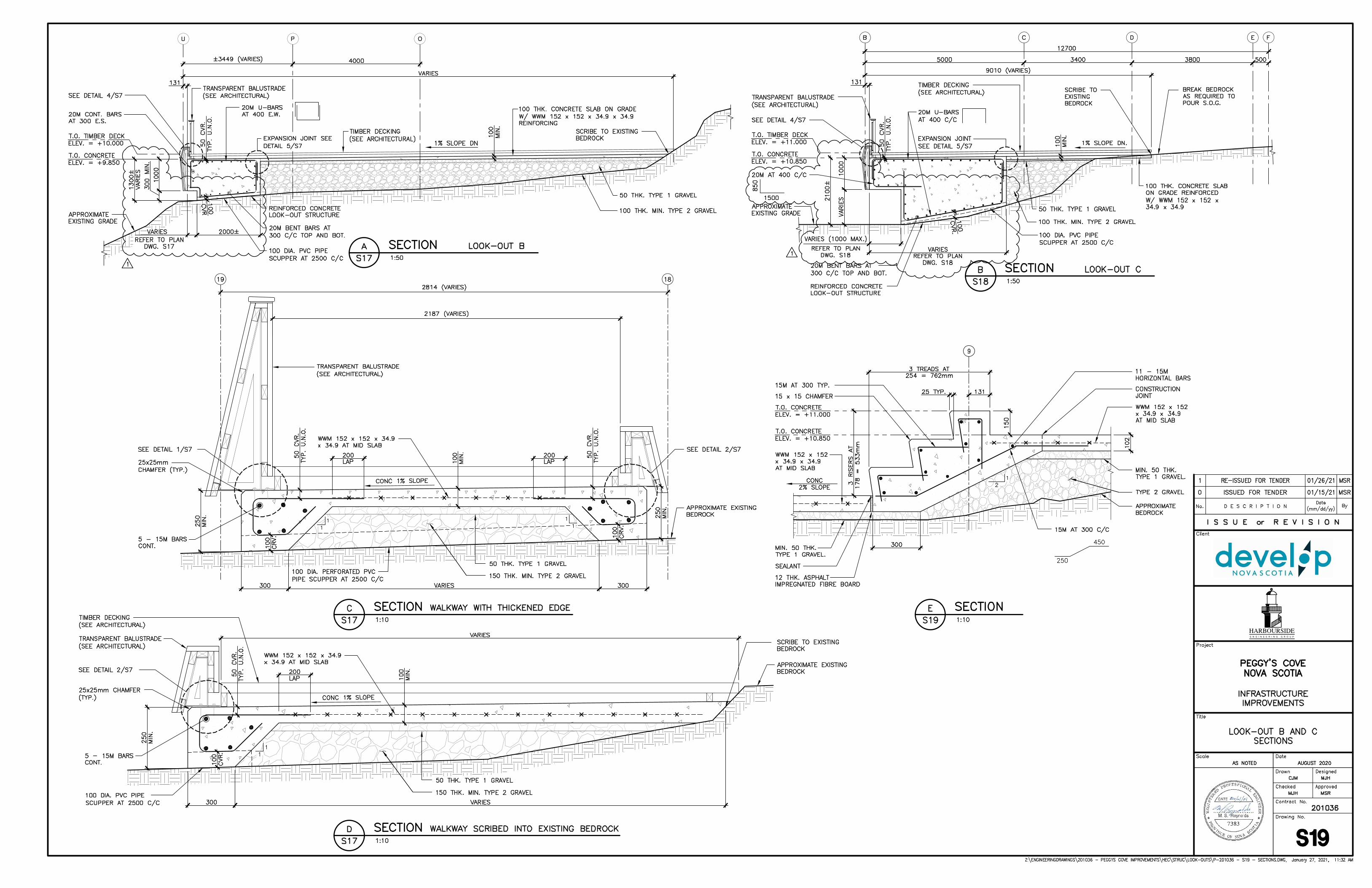
1.3 3D Cad File Data 3D modelling files will not be provided during the RFQ process. The project drawings provide topographic and component data for sufficient grading and quantity take-off purposes. 1.4 Reference Drawing A13 - Details 1 and 2 Cross-sections provided on these pages show Accessible Viewing Deck ‘B’ as being cantilevered. Please note that the structural drawings, particularly S19, should be used as reference for the installation and support of Accessible Viewing Deck ‘B’. Please see S17 to S19 attached below this addendum for more detail. 1.5 Reference Drawing A21 – Details 1 through 4
The spacing for the white cedar cladding will be tapered as required around curved sections to maintain vertical alignment and consistent spacing. A 3mm gap between boards is to be maintained.
1.6 Reference Drawing E2 – Luminaire Schedule
Electrical fixtures were chosen based on the durability and proven reliability of these fixtures in a harsh environment. Finding an equivalent low voltage product may prove difficult. DNS will review potential substitutes with the successful proponent, but for bidding purposes the fixtures shown should be priced for the Pricing Form.
Cast-in-place concrete specifications are included in Section 03 30 00. An alternate concrete mix design may be acceptable, subject to approval of the mix design properties, at the sole discretion of DNS. Please note, the successful proponent is required to submit proposed mix designs at least four (4) weeks in advance of placing concrete to DNS.
During the site meeting, it was stated that concrete pour volumes were included in Section 03 30 00 of the specifications. Please note that precise pour schedules/volumes are not specified in the tender documents. The successful proponent is required to submit their proposed concrete pour schedule to DNS for approval at least four (4) weeks in advance of concrete placement.
Item 2.4.4 indicates that all components are to be stainless steel – grade 316, with No. 4 finish. Please note that ALL stainless steel components are to be stainless steel grade 316, including those references in details on drawing S7.
Please assume that all bottom mat reinforcement identified on the tender drawings for Accessible Viewing Decks ‘A’, ‘B’ and ‘C’ need to be galvanized. In addition, please note that ALL concrete reinforcing should be galvanized. Please see revised S1 attached below.
1.12 Site Logistics Plan
As discussed in the tender, a Site Logistics Plan is included below as Accessible Viewing Deck – Site Logistics Plan – Addendum #1.Please note the entry and exit point at the turnaround. Please refer to the plan for informationon Sou’Wester Restaurant access/egress for patrons, which must be maintained at all times.
There is a legend on the plan delineating: - The location of temporary construction fencing- The location of pylons on the sidewalk edge- Temporary fencing locations for the soon to be tendered Lighthouse Washroom- Delivery routes (in and out by Peggys Point Road Turnaround). Please note that traffic
control will be required to safely enter/exit the worksite from Peggys Point Road iflarge vehicles are maneuvering adjacent to the public roadway.
- The access route for pedestrians from the Sou’Wester Parking Lot to access theLighthouse Pathway and surrounding areas.
- The hatched yellow area is anticipated to be additional laydown space for thecontract.
Please note that the Sou’Wester Parking Lot is a private lot. Parking for work vehicles is prohibited, unless agreed to by the Sou’Wester Representative.
Additionally, coordination with the Lighthouse Washroom contractor will be required with the use of the space based on construction requirements.
2.0 CHANGES
2.1 Reference Drawing A21 – Detail 1
Detail 1 on Drawing A21 indicates a 9.5mm base plate with no grout.
CHANGE WITH:
Detail 1 on Drawing A21 is to be revised to match Detail 4 on S7, with a 19mm thick base plate with 25mm grout. This will be reflected in the IFC Drawing package.
Detail 1 on Drawing A21 has the top mounting plate configuration unclear (at location of curved corners).
CHANGE WITH:
The 6mm top mounting plate is to be curved in the corners of the viewing decks. The detail is to be revised with stiffener between the posts in the IFC drawing package.
Detail 2 on Drawing A21 shows a continuous stainless steel plate attached to a galvanized angle frame. CHANGE WITH: This will be revised to show a 6mm eastern white cedar spacer at the top of the opaque guardrails in the IFC Drawing package. For bidding purposes, please bid based on this data. 2.4 Reference Drawing A21 – Details 2 and 3 – Metal Frames and Grout Details 2 and 3 on Drawing A21 currently show the metal frames being placed directly on the concrete with no grouting. CHANGE WITH: These details are intended to match Details 1 and 2 on Drawing S7, which include the 19mm plate with 25mm grout. This will be revised in the IFC drawing package. 2.5 Reference Drawing A21 – Detail 4 – Handrail Post and Grout Detail 4 on Drawing A21 currently show the handrail posts being placed directly on the concrete with no grouting. CHANGE WITH: These details are intended to match Detail 3 on Drawing S7, which include the 19mm plate with 25mm grout. This will be revised in the IFC drawing package. 2.6 Appendix ‘C’ – Section C.3 Submission Pricing Form There are two linear ‘pile caps’ required for the Accessible Viewing Deck ‘A’ structure. In order to provide clarity with bidding processes, the following changes will be made to the Pricing Form. Accessible Viewing Decks
- Viewing Deck Area ‘A’ o Remove ‘Steel Rock Anchors – Area “A”’ o Replace with ‘Rock Anchors – Area “A”’
o Remove ‘Concrete Foundation (Incl. Reinforcement, anchors, etc.) – Viewing
Deck Area “A” o Replace with “Concrete Foundation (Incl. Reinforcement, Etc.) – Viewing Deck
Area “A” Please see below for revised Appendix C – Submission Pricing Form – Addendum #1 showing these changes.
2.7 Part 2 - Evaluation and Negotiation – Item 2.2.4 Other Mandatory Submission Requirements
REMOVE: d. Statement of Insurability (Refer to Appendix D, Item D.3.1) REPLACE WITH (Revised Part 2 – Evaluation and Negotiation – Addendum #1 Attached Below):
d. Statement of Insurability
The respondent must provide a Statement of Insurability from a duly licensed Canadian insurance company or insurance brokerage firm confirming the respondent’s ability to obtain the following insurance policies:
1. General Liability Insurance covering for the benefit of Develop Nova Scotia, the Supplier, Sub Contractors, the Construction Manager, Consultants, and other such persons, firms and Corporations as Develop Nova Scotia may determine with a limit of liability per occurrence for bodily injury, death and property damage in an amount of $5,000,000.00.
2. “All Risks” Insurance or Builder’s Risk Insurance covering owned, and non-owned mobile equipment, property and construction tools, machinery and equipment used by the Supplier for the performance of the work, including boiler insurance on temporary boilers and pressure vessels.
3. Automobile Liability Insurance with respect to automobiles used directly or indirectly in the performance of the work and which are owned, leased, or used by the Supplier and covering liability for bodily injury, death and property damage with a limit of not less than $2,000,000.00 inclusive for each and every loss.
4. The Supplier shall provide Develop Nova Scotia with a Certificate of Insurance that names Develop Nova Scotia as an additional insured.
5. The Supplier shall at all times pay or cause to be paid any assessment or compensation required to be paid pursuant to the Workers’ Compensation Act.
6. The Suppler unconditionally guarantees to Develop Nova Scotia full compliance with the conditions, regulations and laws relating to Workers’ Compensation by itself and by all Sub Contractors.
This addendum WILL NOT require a revision to the Closing Date and Time, or other dates given in the Request for Proposal document. The closing date and time will remain 2:00 pm AT on February 3rd, 2021.
In accordance with Section C.7 of Appendix C – Submission Pricing Form, Proponents are deemed to have read and taken into account all addenda issued by Develop Nova Scotia. For further information prospective Proponents should contact Tim Jordan, Project Manager at [email protected]
GENERAL NOTES: 1. GENERAL REQUIREMENTS GOVERNING DESIGN, MATERIALS, AND CONSTRUCTION ARE AS GENERAL REQUIREMENTS GOVERNING DESIGN, MATERIALS, AND CONSTRUCTION ARE AS FOLLOWS: A. GENERAL DESIGN TO THE 2015 NATIONAL BUILDING CODE OF CANADA AND GENERAL DESIGN TO THE 2015 NATIONAL BUILDING CODE OF CANADA AND CAN/CSA-S6-14, INCLUDING LATEST REVISIONS. B. LOOK-OUT STRUCTURE SLS LIVE LOADS: LOOK-OUT STRUCTURE SLS LIVE LOADS: i. UNIFORM LIVE LOAD: 5 kPa UNIFORM LIVE LOAD: 5 kPa ii. SNOW LOADS: AS PER NBCC 2015 iii. DESIGN MAINTENANCE VEHICLE (CSA S6-19) FOR LOOK-OUT STRUCTURE DESIGN DESIGN MAINTENANCE VEHICLE (CSA S6-19) FOR LOOK-OUT STRUCTURE DESIGN (NOT SIMULTANEOUS WITH LOOK-OUT STRUCTURE UNIFORM LIVE LOAD): C. UNLESS NOTED OTHERWISE, ALL WORK AND MATERIALS SHALL CONFORM TO THE UNLESS NOTED OTHERWISE, ALL WORK AND MATERIALS SHALL CONFORM TO THE REQUIREMENTS SET OUT IN THE 2015 NATIONAL BUILDING CODE OF CANADA, AS APPLICABLE. D. ALL WORK IS TO BE CARRIED OUT IN ACCORDANCE WITH THE NOVA SCOTIA ALL WORK IS TO BE CARRIED OUT IN ACCORDANCE WITH THE NOVA SCOTIA OCCUPATIONAL HEALTH & SAFETY ACT. E. REFERENCE CIP CONCRETE NOTES BELOW REFERENCE CIP CONCRETE NOTES BELOW F. REFERENCE REINFORCING STEEL NOTES BELOW REFERENCE REINFORCING STEEL NOTES BELOW G. REFERENCE FORMWORK NOTES BELOW REFERENCE FORMWORK NOTES BELOW 2. ALL STANDARDS AND SPECIFICATION NOTES TO REFLECT THE “LATEST EDITION” AT THE TIME ALL STANDARDS AND SPECIFICATION NOTES TO REFLECT THE “LATEST EDITION” AT THE TIME LATEST EDITION” AT THE TIME AT THE TIME OF ISSUED FOR CONSTRUCTION DRAWINGS. 3. LOOK-OUT STRUCTURE AND BUILDING GEOMETRY BASED ON OMAR GANDHI ARCHITECT LOOK-OUT STRUCTURE AND BUILDING GEOMETRY BASED ON OMAR GANDHI ARCHITECT DRAWINGS. ANY DISCREPANCIES BETWEEN THE ARCHITECTURAL AND SUB-TRADE DRAWINGS ARE NOT THE RESPONSIBILITY OF HEC. 4. ALL DIMENSIONS SHOWN IN METRIC UNITS UNO. ALL DIMENSIONS SHOWN IN METRIC UNITS UNO. 5. FOUNDATION DESIGNS BASED ON THE FOLLOWING REFERENCES: FOUNDATION DESIGNS BASED ON THE FOLLOWING REFERENCES: A. GEOTECHNICAL INVESTIGATION - PEGGY'S COVE INFRASTRUCTURE DEVELOPMENT, FILE GEOTECHNICAL INVESTIGATION - PEGGY'S COVE INFRASTRUCTURE DEVELOPMENT, FILE NO. 203018, DATED MAY 21 2020, BY HARBOURSIDE GEOTECHNICAL CONSULTANTS. NEITHER THE OWNER OR THE ENGINEER ACCEPTS ANY RESPONSIBILITY FOR THE ACCURACY OF INFORMATION PROVIDED IN THE ABOVE LISTED REFERENCES. THE USE OF THESE DOCUMENTS OR MAKING INFERENCES REGARDING REQUIREMENTS FOR WORK BASED ON THESE DOCUMENTS SHALL BE AT THE SOLE RISK OF THE CONTRACTOR. 6. ANY EXCAVATION WITHIN THE INFLUENCE ZONE OF EXISTING FOUNDATIONS MUST BE ANY EXCAVATION WITHIN THE INFLUENCE ZONE OF EXISTING FOUNDATIONS MUST BE APPROVED PRIOR TO COMMENCEMENT. 7. PRIOR TO INITIATING CONSTRUCTION, THE CONTRACTOR SHALL CONFIRM ALL DIMENSIONS PRIOR TO INITIATING CONSTRUCTION, THE CONTRACTOR SHALL CONFIRM ALL DIMENSIONS AND REPORT ANY DISCREPANCIES TO THE ENGINEER. 8. CONTRACTOR TO CONFIRM EXISTING STRUCTURE RELATED DIMENSIONS IN THE FIELD BEFORE CONTRACTOR TO CONFIRM EXISTING STRUCTURE RELATED DIMENSIONS IN THE FIELD BEFORE PROCEEDING WITH THE WORK. 9. ALL TRADES SHALL SUBMIT SHOP DRAWINGS STAMPED BY A PROFESSIONAL ENGINEER ALL TRADES SHALL SUBMIT SHOP DRAWINGS STAMPED BY A PROFESSIONAL ENGINEER LICENSED TO PRACTICE IN NOVA SCOTIA, PRIOR TO COMMENCEMENT OF FABRICATION. 10. ALL ELEVATIONS SHOWN ARE WITH RESPECT TO CANADIAN GEODETIC DATUM CGVD2013, ALL ELEVATIONS SHOWN ARE WITH RESPECT TO CANADIAN GEODETIC DATUM CGVD2013, UNLESS NOTED OTHERWISE. HORIZONTAL COORDINATED SYSTEM SYSTEM BASED ON NAD83 UTM ZONE 20. 11. WORK SHALL BE CARRIED OUT IN ACCORDANCE WITH NOVA SCOTIA DEPARTMENT OF WORK SHALL BE CARRIED OUT IN ACCORDANCE WITH NOVA SCOTIA DEPARTMENT OF ENVIRONMENT REQUIREMENTS. 12. CONTRACTOR TO PROVIDE EROSION AND SEDIMENTATION CONTROL PLAN TO THE ENGINEER CONTRACTOR TO PROVIDE EROSION AND SEDIMENTATION CONTROL PLAN TO THE ENGINEER AT THE START OF THE PROJECT FOR ALL PHASES OF WORK AND MAINTAIN CONTROLS THROUGHOUT CONSTRUCTION. 13. CONTRACTOR SHALL DEVELOP A SAFE WORK PLAN TO BE SUBMITTED TO CLIENT CONTRACTOR SHALL DEVELOP A SAFE WORK PLAN TO BE SUBMITTED TO CLIENT REPRESENTATIVE FOR REVIEW PRIOR TO INITIATING CONSTRUCTION. 14. FINAL ORIENTATION OF TIMBER WEARING SURFACE TO BE COORDINATED WITH ARCHITECT AT FINAL ORIENTATION OF TIMBER WEARING SURFACE TO BE COORDINATED WITH ARCHITECT AT START OF CONSTRUCTION. 15. REFER TO PROJECT ARCHITECTURAL DRAWINGS FOR LOOK-OUT STRUCTURE FINISHES. REFER TO PROJECT ARCHITECTURAL DRAWINGS FOR LOOK-OUT STRUCTURE FINISHES. 16. CONTRACTOR IS REQUIRED TO FAMILIARIZE HIMSELF WITH EXISTING CONDITIONS WITHIN THE CONTRACTOR IS REQUIRED TO FAMILIARIZE HIMSELF WITH EXISTING CONDITIONS WITHIN THE SITE BOUNDARIES SHOWN ON DRAWING S2 SITE PLAN FOR LOOKOUT A, LOOKOUT B & LOOKOUT C. THE REMOVAL OF EXISTING BOULDERS THAT INTERFERE WITH THE NEW STRUCTURES SHOWN ON DRAWING S2, AND TRANSPORTATION TO ELSEWHERE WITHIN PEGGY'S COVE AS DIRECTED BY DEVELOP NOVA SCOTIA, IS TO BE INCLUDED UNDER THIS CONTRACT. CAST-IN-PLACE CONCRETE NOTES: 1. ALL EXPOSED CORNERS OF CONCRETE TO HAVE 25mm / 1 INCH CHAMFERS. ALL EXPOSED CORNERS OF CONCRETE TO HAVE 25mm / 1 INCH CHAMFERS. 2. LOCATION OF CONSTRUCTION JOINTS AND SEQUENCE OF CONCRETE PLACEMENT TO BE LOCATION OF CONSTRUCTION JOINTS AND SEQUENCE OF CONCRETE PLACEMENT TO BE APPROVED BY THE ENGINEER. 3. CONCRETE MATERIAL REQUIREMENTS: CONCRETE MATERIAL REQUIREMENTS: A. ALL CONCRETE MATERIALS, MIX DESIGN SHALL CONFORM TO CSA-A23.1-14 ALL CONCRETE MATERIALS, MIX DESIGN SHALL CONFORM TO CSA-A23.1-14 B. ALL CONCRETE EXCEPT LOOK-OFF A SHALL BE TYPE C1 AND SHALL HAVE A MINIMUM ALL CONCRETE EXCEPT LOOK-OFF A SHALL BE TYPE C1 AND SHALL HAVE A MINIMUM COMPRESSIVE STRENGTH OF 35 MPa AT 28 DAYS. LOOK-OFF A CONCRETE SHALL BE TO NSTIR STANDARD SPECIFICATION TYPE HPC AND SHALL HAVE A MINIMUM COMPRESSIVE STRENGTH OF 45 MPa AT 28 DAYS C. ALL CONCRETE SHALL CONTAIN 6% ± 1% ENTRAINED AIR. ALL CONCRETE SHALL CONTAIN 6% ± 1% ENTRAINED AIR. D. ALL CONCRETE ADDITIVES SHALL BE APPROVED BY THE ENGINEER. ALL CONCRETE ADDITIVES SHALL BE APPROVED BY THE ENGINEER. 4. ALL CONCRETE CURING SHALL CONFORM TO CSA-A23.1-14. ALL CONCRETE SHALL BE WET ALL CONCRETE CURING SHALL CONFORM TO CSA-A23.1-14. ALL CONCRETE SHALL BE WET CURED FOR 7 DAYS OR UNTIL COMPONENT ATTAINS 70% OF THE SPECIFIED STRENGTH, WHICHEVER LONGER. 5. ALL CONCRETE SHALL BE TESTED IN ACCORDANCE WITH CSA-A23.2-14. ALL CONCRETE SHALL BE TESTED IN ACCORDANCE WITH CSA-A23.2-14. 6. FOR COMPRESSIVE STRENGTH TESTING OF CONCRETE A MINIMUM OF 3 - 6X12 CYLINDERS FOR COMPRESSIVE STRENGTH TESTING OF CONCRETE A MINIMUM OF 3 - 6X12 CYLINDERS ARE REQUIRED FOR: A. EACH DAY'S POUR EACH DAY'S POUR B. EACH CHANGE OF SUPPLIER EACH CHANGE OF SUPPLIER C. EACH 20 m OR FRACTION THEREOF FOR ROCK ANCHORS EACH 20 m OR FRACTION THEREOF FOR ROCK ANCHORS 3 OR FRACTION THEREOF FOR ROCK ANCHORS D. EACH 30 m OR FRACTION THEREOF FOR C.I.P. CONCRETE EACH 30 m OR FRACTION THEREOF FOR C.I.P. CONCRETE 3 OR FRACTION THEREOF FOR C.I.P. CONCRETE E. ADDITIONAL TEST SPECIMENS SHALL BE TAKEN WHENEVER REQUESTED BY THE DEVELOP ADDITIONAL TEST SPECIMENS SHALL BE TAKEN WHENEVER REQUESTED BY THE DEVELOP N.S. OR THE SUPERVISOR TO VERIFY THE CONCRETE QUALITY. 7. NO CONCRETE SHALL BE PLACED WITHOUT PRIOR APPROVAL OF THE ENGINEER. NO CONCRETE SHALL BE PLACED WITHOUT PRIOR APPROVAL OF THE ENGINEER. 8. EACH PHASE OF WORK TO BE INSPECTED BY THE OWNER'S REPRESENTATIVE PRIOR TO EACH PHASE OF WORK TO BE INSPECTED BY THE OWNER'S REPRESENTATIVE PRIOR TO PROCEEDING TO THE NEXT PHASE OF WORK. 9. ALL EMBEDDED ITEMS SHALL BE ACCURATELY INSTALLED PRIOR TO CASTING CONCRETE ALL EMBEDDED ITEMS SHALL BE ACCURATELY INSTALLED PRIOR TO CASTING CONCRETE USING TEMPLATES TO ENSURE PROPER LOCATION, POSITIONING AND ORIENTATION AFTER CONCRETE IS CAST AND CURED. CONTRACTOR TO PROVIDE ADDITIONAL REINFORCING, TEMPLATES, ETC. AS NECESSARY TO ENSURE THAT CASTING OPERATIONS DO NOT ALTER THE POSITION OR ORIENTATION OF EMBEDMENTS. REFERENCE NOTE 10 IN REINFORCING STEEL NOTES FOR REQUIREMENTS TO ISOLATE DISSIMILAR METALS. 10. COMPACTING IMMEDIATELY ADJACENT TO EXISTING STRUCTURES SHALL BE ACCOMPLISHED COMPACTING IMMEDIATELY ADJACENT TO EXISTING STRUCTURES SHALL BE ACCOMPLISHED WITH LIGHT COMPACTING EQUIPMENT. MODERATE COMPACTING WITH A TRENCH ROLLER IN 300mm LIFTS ELSEWHERE (ALL COMPACTION SHALL BE TO 98% STD. PROCTOR DENSITY). SURCHARGES FROM CONSTRUCTION EQUIPMENT TO BE AVOIDED UNLESS OTHERWISE APPROVED BY ENGINEER IN WRITING. REINFORCING STEEL NOTES: 1. ALL REINFORCING STEEL SHALL HAVE A MINIMUM YIELD STRENGTH OF 400 MPa AND SHALL ALL REINFORCING STEEL SHALL HAVE A MINIMUM YIELD STRENGTH OF 400 MPa AND SHALL CONFORM TO CSA G30.18-09 (R2014), EXCEPT ALL GALVANIZED REINFORCING SHALL BE GRADE 400W DEFORMED BARS WITH YIELD STRENGTH OF 400 MPa (WELDABLE). ALL REINFORCING STEEL SHALL BE DETAILED, FABRICATED, PLACED AND SUPPORTED IN ACCORDANCE WITH REINFORCING STEEL MANUAL OF STANDARD PRACTICE (FOURTH EDITION, 2004) BY THE REINFORCING STEEL INSTITUTE OF CANADA AND CSA-A23.3-14, EXCEPT AS INDICATED IN NOTE 2 BELOW. 2. FOR GALVANIZED BENT STEEL REINFORCING BAR TYPES REFER TO R.S.I.C. REINFORCING FOR GALVANIZED BENT STEEL REINFORCING BAR TYPES REFER TO R.S.I.C. REINFORCING MANUAL OF STANDARD PRACTICE TYPICAL BAR BENDS EXCEPT BAR BEND DIAMETERS AS PER TABLE 1, BELOW. 3. BEND REINFORCING PRIOR TO GALVANIZING, FIELD BENDING OF GALVANIZED BARS IS NOT BEND REINFORCING PRIOR TO GALVANIZING, FIELD BENDING OF GALVANIZED BARS IS NOT PERMITTED. 4. CONCRETE COVER TO REINFORCING STEEL AS NOTED ON DRAWINGS. CONCRETE COVER TO REINFORCING STEEL AS NOTED ON DRAWINGS. 5. REINFORCING LAPS AS INDICATED ON THE DRAWINGS. REINFORCING LAPS AS INDICATED ON THE DRAWINGS. 6. ALL REINFORCING STEEL TO BE ACCURATELY SUPPORTED ON NON-CORROSIVE SUPPORTS ALL REINFORCING STEEL TO BE ACCURATELY SUPPORTED ON NON-CORROSIVE SUPPORTS APPROVED BY THE ENGINEER. 7. ALL REINFORCEMENT TO BE INSPECTED BY THE OWNER'S REPRESENTATIVE PRIOR TO ALL REINFORCEMENT TO BE INSPECTED BY THE OWNER'S REPRESENTATIVE PRIOR TO CLOSING FORMWORK OR PLACING CONCRETE. 8. THE CONTRACTOR SHALL PROVIDE CONTINUOUS SUPERVISION DURING THE PLACEMENT OF THE CONTRACTOR SHALL PROVIDE CONTINUOUS SUPERVISION DURING THE PLACEMENT OF CONCRETE TO ENSURE THAT THE REINFORCING STEEL IS MAINTAINED IN ITS CORRECT POSITION. 9. HOT-DIP GALVANIZED REINFORCING IS REQUIRED FOR ALL LOOKOUT A REINFORCEMENT HOT-DIP GALVANIZED REINFORCING IS REQUIRED FOR ALL LOOKOUT A REINFORCEMENT BARS ONLY. 10. TO AVOID CONTACT BETWEEN DISSIMILAR METALS, WHERE GALVANIZED BARS COME IN TO AVOID CONTACT BETWEEN DISSIMILAR METALS, WHERE GALVANIZED BARS COME IN CONTACT WITH UNCOATED STEEL, EITHER A 40 MM MINIMUM CLEAR SEPARATION SHALL BE PROVIDED BETWEEN THE BARS OR THE UNCOATED BAR SHALL BE WRAPPED LOCALLY AT THE CONTACT POINT IN A THICK LAYER OF DENSO TAPE MEETING THE APPROVAL OF THE ENGINEER. 11. GALVANIZED COATED REINFORCING TO BE HOT-DIP GALVANIZED TO CSA-G164-M92 GALVANIZED COATED REINFORCING TO BE HOT-DIP GALVANIZED TO CSA-G164-M92 (R2003). MINIMUM COATING OF 2oz./ft . 2 . 12. ALL REINFORCING STEEL SHALL BE WASHED CLEAN OF SALT, GREASE, DIRT OR OTHER ALL REINFORCING STEEL SHALL BE WASHED CLEAN OF SALT, GREASE, DIRT OR OTHER CONTAMINANTS PRIOR TO CASTING CONCRETE. FORMWORK NOTES: 1. DESIGN, CONSTRUCT AND REMOVE FORMWORK, FRAMING SUPPORTS AND TEMPORARY DESIGN, CONSTRUCT AND REMOVE FORMWORK, FRAMING SUPPORTS AND TEMPORARY BRACING TO CSA-A23.1-14, AND CSA S269.1-1975. 2. FINISHED CONCRETE SURFACE TOLERANCES AND CONCRETE ELEMENT SIZE, STRAIGHTNESS, FINISHED CONCRETE SURFACE TOLERANCES AND CONCRETE ELEMENT SIZE, STRAIGHTNESS, ETC. TO BE WITHIN SPECIFIED TOLERANCES IN CSA-A23.1-14. 3. CHAMFER ALL CONCRETE CORNERS WITH A 25mm / 1” CHAMFER, UNLESS NOTED CHAMFER ALL CONCRETE CORNERS WITH A 25mm / 1” CHAMFER, UNLESS NOTED CHAMFER, UNLESS NOTED OTHERWISE ON THE DRAWINGS. 4. INSTALL ITEMS SUPPLIED BY OTHERS SUCH AS INSERTS, ANCHOR BOLTS, MISCELLANEOUS INSTALL ITEMS SUPPLIED BY OTHERS SUCH AS INSERTS, ANCHOR BOLTS, MISCELLANEOUS FRAMES, METAL FLASHING REGLETS, HOLES, SLEEVES, LADDER RUNGS AND DOVETAIL ANCHOR SLOTS. 5. FORMS AND BRACING SHALL NOT BE REMOVED UNTIL THE CONCRETE HAS CURED AND FORMS AND BRACING SHALL NOT BE REMOVED UNTIL THE CONCRETE HAS CURED AND REACHED 75% OF f'c AND WRITTEN PERMISSION FROM THE ENGINEER IS PROVIDED. 6. NO OPENINGS SHALL BE MADE IN SUSPENDED SLABS OR CAP BEAMS BEYOND THOSE NO OPENINGS SHALL BE MADE IN SUSPENDED SLABS OR CAP BEAMS BEYOND THOSE DETAILED ON THE DRAWINGS WITHOUT SPECIFIC WRITTEN APPROVAL FROM THE ENGINEER. 7. REMOVE ALL FINS FROM VISIBLE SURFACES. FILL ALL TIE HOLES WITH NON SHRINK GROUT REMOVE ALL FINS FROM VISIBLE SURFACES. FILL ALL TIE HOLES WITH NON SHRINK GROUT WITH A MINIMUM COMPRESSIVE STRENGTH AT 28 DAYS OF 45 MPa.
AutoCAD SHX Text
13.5kN
AutoCAD SHX Text
31kN
AutoCAD SHX Text
13.5kN
AutoCAD SHX Text
31kN
AutoCAD SHX Text
FRONT AXLE
AutoCAD SHX Text
REAR AXLE
AutoCAD SHX Text
MINIMUM BEND DIAMETER FOR REINFORCING STEEL, GALVANIZED AND UNCOATED BAR
AutoCAD SHX Text
BAR SIZE (mm)
AutoCAD SHX Text
BEND DIAMETER (mm)
AutoCAD SHX Text
10
AutoCAD SHX Text
70
AutoCAD SHX Text
15
AutoCAD SHX Text
90
AutoCAD SHX Text
20
AutoCAD SHX Text
150
AutoCAD SHX Text
25
AutoCAD SHX Text
200
AutoCAD SHX Text
30
AutoCAD SHX Text
250
AutoCAD SHX Text
35
AutoCAD SHX Text
300
AutoCAD SHX Text
45
AutoCAD SHX Text
450
AutoCAD SHX Text
55
AutoCAD SHX Text
600
AutoCAD SHX Text
SELF WEIGHT OF TRUSS SUPERIMPOSED DEAD LOAD = 1.4 kPa, INCLUDING MECHANICAL AND ELECTRICAL WIND LOAD - q (1/50) = 0.58 kPa - Iw = 1 SNOW LOAD - Ss = 1.9, Sr = 0.6, Is = 1, s = 1.0 kPa LIVE LOAD = 1.0 kPa DEAD LOAD - 2.5 kN POINT LOAD ANYWHERE ON BOTTOM CHORD OF TRUSS
AutoCAD SHX Text
ROOF DESIGN LOADS:
AutoCAD SHX Text
1. DO CONCRETE WORK TO CSA A23.1-14 AND TESTING TO A23.2-14 BY AN AGENCY DO CONCRETE WORK TO CSA A23.1-14 AND TESTING TO A23.2-14 BY AN AGENCY APPROVED BY AND RESPONSIBLE TO DNS AND PAID FOR BY THE OWNER. 2. ALL CONCRETE SHALL BE NORMAL WEIGHT 2400 kg/m AND SHALL BE CLASS F2, MIN. 25 ALL CONCRETE SHALL BE NORMAL WEIGHT 2400 kg/m AND SHALL BE CLASS F2, MIN. 25 MPa. AIR ENTRAINMENT TO BE 4% - 7% WITH A MAXIMUM AGGREGATE SIZE OF 20mm. 3. PRIOR TO PLACING CONCRETE, ENSURE THAT ALL REINFORCING STEEL IS CLEAN, FREE OF PRIOR TO PLACING CONCRETE, ENSURE THAT ALL REINFORCING STEEL IS CLEAN, FREE OF LOOSE SCALE, RUST, MUD, OIL, OR OTHER FOREIGN MATERIAL THAT WOULD REDUCE BOND. 4. SLEEVES ARE TO BE PROVIDED AT LOCATIONS WHERE MECHANICAL AND ELECTRICAL PIPES SLEEVES ARE TO BE PROVIDED AT LOCATIONS WHERE MECHANICAL AND ELECTRICAL PIPES AND CONDUITS PENETRATE THE CONCRETE SLAB AND WALLS. CONCRETE CORING SHALL BE AVOIDED. 5. SLOPE SLAB TOWARDS PIT, TYPICAL, REFER TO MECHANICAL FOR LOCATION. SLOPE SLAB TOWARDS PIT, TYPICAL, REFER TO MECHANICAL FOR LOCATION. 6. PROVIDE 75mm CLEAR COVER TO ALL REINFORCING STEEL UNLESS NOTED OTHERWISE. PROVIDE 75mm CLEAR COVER TO ALL REINFORCING STEEL UNLESS NOTED OTHERWISE. 7. CONCRETE STEPS SHALL BE SLOPED BY 1% TOWARDS LEVEL 0. CONCRETE STEPS SHALL BE SLOPED BY 1% TOWARDS LEVEL 0. 8. PROVIDE A 20mm CHAMFER, ALL EXPOSED CORNERS OF CONCRETE. PROVIDE A 20mm CHAMFER, ALL EXPOSED CORNERS OF CONCRETE. 9. MIX DESIGNS TO BE REVIEWED AND ACCEPTED BEFORE PLACEMENT.MIX DESIGNS TO BE REVIEWED AND ACCEPTED BEFORE PLACEMENT.
AutoCAD SHX Text
BUILDING CONCRETE NOTES:
AutoCAD SHX Text
1. ALL ROOF TRUSSES SHALL BE DESIGNED TO NBCC 2015 DESIGN CRITERIA, FABRICATED ALL ROOF TRUSSES SHALL BE DESIGNED TO NBCC 2015 DESIGN CRITERIA, FABRICATED AND INSTALLED IN ACCORDANCE WITH CSA 086-14. ALL LUMBER SHALL BE SPF No. 1/2 UNLESS OTHERWISE NOTED. LIMIT LIVE LOAD DEFLECTIONS TO L/360 OF A SPAN. 2. THE DESIGN AND SPECIFICATION OF PERMANENT TRUSS BRACING TO PROVIDE LATERAL THE DESIGN AND SPECIFICATION OF PERMANENT TRUSS BRACING TO PROVIDE LATERAL SUPPORT TO WEB AND CHORD MEMBERS IS THE RESPONSIBILITY OF THE TRUSS MANUFACTURER. 3. SUBMIT TRUSS SHOP DRAWINGS AND TRUSS LOCATION PLANS TO SHOW BEARING SUBMIT TRUSS SHOP DRAWINGS AND TRUSS LOCATION PLANS TO SHOW BEARING CONNECTIONS, HANGERS AND TIE-DOWNS, MEMBER SIZES, AND DETAILS, ETC. FOR DNS REVIEW PRIOR TO FABRICATION. SHOP DRAWINGS SHOULD ALSO INCLUDE TRUSS ERECTION DRAWING SHOWING TEMPORARY BRIDGING. SHOP DRAWINGS SHALL BEAR THE STAMP OF A PROFESSIONAL ENGINEER LICENSED TO PRACTICE IN THE PROVINCE OF NOVA SCOTIA. 4. PROVIDE UPLIFT CONNECTIONS AT EACH TRUSS BEARING POINT FOR WIND UPLIFT ON ROOF. PROVIDE UPLIFT CONNECTIONS AT EACH TRUSS BEARING POINT FOR WIND UPLIFT ON ROOF. UPLIFT CONNECTIONS TO BE DESIGNED IN ACCORDANCE TO LOADING STATED IN DESIGN CRITERIA. 5. ALL ROOF TRUSSES SHALL BE SPACED AT 610mm (24") O/C MAXIMUM UNLESS NOTED ALL ROOF TRUSSES SHALL BE SPACED AT 610mm (24") O/C MAXIMUM UNLESS NOTED OTHERWISE. 6. ALL NAILS, SPIKES AND STAPLES SHALL BE IN ACCORDANCE WITH NBCC 2015. ALL NAILS, SPIKES AND STAPLES SHALL BE IN ACCORDANCE WITH NBCC 2015. 7. CUTTING OF HOLES ON STRUCTURAL FRAMING MEMBERS SHALL NOT BE PERMITTED CUTTING OF HOLES ON STRUCTURAL FRAMING MEMBERS SHALL NOT BE PERMITTED WITHOUT WRITTEN APPROVAL FROM DNS. 8. HANGING OF MECHANICAL PIPING AND DUCT WORK FROM TRUSS CHORDS SHALL BE AS HANGING OF MECHANICAL PIPING AND DUCT WORK FROM TRUSS CHORDS SHALL BE AS PER JOIST AND TRUSS MANUFACTURER'S RECOMMENDATION. 9. ANCHOR BOLTS TO BE 5/8" GALVANIZED A307 GRADE C THREADED ROD. ANCHOR BOLTS TO BE 5/8" GALVANIZED A307 GRADE C THREADED ROD.10. BUILT UP BEAMS TO BE SPLICED AND FASTENED IN ACCORDANCE WITH CSA 086-14. 2 BUILT UP BEAMS TO BE SPLICED AND FASTENED IN ACCORDANCE WITH CSA 086-14. 2 FASTENERS EVERY 450mm C/C MAX, 150mm MAX FROM EACH END, STAGGER ROWS ON EACH FACE OF BUILT UP BEAM. FASTENERS TO BE 100mm LONG COMMON NAILS, 64mm LONG FOR 2 PLY.
AutoCAD SHX Text
WOOD AND CONNECTION NOTES:
AutoCAD SHX Text
BEARING NOTES: 1. ELASTOMETRIC BEARINGS SHALL BE MANUFACTURED AND PLACED IN ACCORDANCE WITH ELASTOMETRIC BEARINGS SHALL BE MANUFACTURED AND PLACED IN ACCORDANCE WITH CAN/CSA S6-19, CANADIAN HIGHWAY BRIDGE DESIGN CODE: a. BEARINGS SHALL BE PLAIN 60 DURO (SHORE A) RUBBER BEARINGS AS PER ASTM BEARINGS SHALL BE PLAIN 60 DURO (SHORE A) RUBBER BEARINGS AS PER ASTM D2240. b. PHYSICAL PROPERTIES OF ELASTOMETRIC BEARING PADS SHALL BE IN ACCORDANCE PHYSICAL PROPERTIES OF ELASTOMETRIC BEARING PADS SHALL BE IN ACCORDANCE WITH TABLE 11.5 OF CAN/CSA S6-19. c. PRIOR TO THE APPLICATION OF LOADS THE TOP AND BOTTOM FACES OF THE BEARING PRIOR TO THE APPLICATION OF LOADS THE TOP AND BOTTOM FACES OF THE BEARING PAD SHALL BE CO-PLANAR WITHIN A FABRICATION TOLERANCE OF ±0.005 rad. AND ACONSTRUCTION PLACEMENT TOLERANCE OF ±0.0035 rad.2. ELASTOMETRIC BEARINGS WERE DESIGNED AS FREE, COMPRESSION ONLY BEARINGS ON THE ELASTOMETRIC BEARINGS WERE DESIGNED AS FREE, COMPRESSION ONLY BEARINGS ON THE FOLLOWING GOVERNING LOADS AND MOVEMENTS (PER BEARING): a, SPECIFIED DEAD LOAD = 105kN SPECIFIED DEAD LOAD = 105kN 105kN b. SPECIFIED TOTAL LOAD = 140kN SPECIFIED TOTAL LOAD = 140kN 140kN c. FACTORED MAX. PERMANENT LOAD = 126kN FACTORED MAX. PERMANENT LOAD = 126kN d. FACTORED MAX. TOTAL LOAD = 268kN FACTORED MAX. TOTAL LOAD = 268kN e. SPECIFIED *MAX. LONGITUDINAL MOVEMENT = +2mm SPECIFIED *MAX. LONGITUDINAL MOVEMENT = +2mm f. SPECIFIED *MIN. LONGITUDINAL MOVEMENT = -6mm SPECIFIED *MIN. LONGITUDINAL MOVEMENT = -6mm g. SPECIFIED TRANSVERSE MOVEMENT = 5mm SPECIFIED TRANSVERSE MOVEMENT = ±5mm* (+) LONGITUDINAL MOVEMENT IS TAKEN AS MOVEMENT IN THE EXPANSIVE DIRECTION (ie: (+) LONGITUDINAL MOVEMENT IS TAKEN AS MOVEMENT IN THE EXPANSIVE DIRECTION (ie: (ie: THE SLAB MOVING AWAY FROM THE FRONT ROCK ANCHORS. 3. A CONSTRUCTION TEMPERATURE OF 15 C WAS ASSUMED IN DESIGN. BEARING THERMAL A CONSTRUCTION TEMPERATURE OF 15°C WAS ASSUMED IN DESIGN. BEARING THERMALMOVEMENTS ARE ILLUSTRATED BELOW:
AutoCAD SHX Text
TOTAL CONTRACTION (-23°)
AutoCAD SHX Text
(+34°) TOTAL EXPANSION
AutoCAD SHX Text
+15°
AutoCAD SHX Text
LONGITUDINAL THERMAL MOVEMENTS
AutoCAD SHX Text
N.I.C.
AutoCAD SHX Text
N.I.C.
AutoCAD SHX Text
1
AutoCAD SHX Text
RE-ISSUED FOR TENDER
AutoCAD SHX Text
01/26/21
AutoCAD SHX Text
MSR
AutoCAD SHX Text
1
HARBOURSIDEE N G I N E E R I N G G R O U P
AutoCAD SHX Text
W
AutoCAD SHX Text
V
AutoCAD SHX Text
14
AutoCAD SHX Text
18
AutoCAD SHX Text
12
AutoCAD SHX Text
11
AutoCAD SHX Text
P
AutoCAD SHX Text
O
AutoCAD SHX Text
U
AutoCAD SHX Text
T
AutoCAD SHX Text
S
AutoCAD SHX Text
WALKWAY
AutoCAD SHX Text
WALKWAY
AutoCAD SHX Text
+12.500
AutoCAD SHX Text
+12.500
AutoCAD SHX Text
+13.000
AutoCAD SHX Text
+13.500
AutoCAD SHX Text
+9.500
AutoCAD SHX Text
+9.000
AutoCAD SHX Text
+8.500
AutoCAD SHX Text
+8.000
AutoCAD SHX Text
+7.500
AutoCAD SHX Text
+7.000
AutoCAD SHX Text
+6.500
AutoCAD SHX Text
+6.000
AutoCAD SHX Text
+5.500
AutoCAD SHX Text
+5.000
AutoCAD SHX Text
19
AutoCAD SHX Text
18
AutoCAD SHX Text
C
AutoCAD SHX Text
S19
AutoCAD SHX Text
A
AutoCAD SHX Text
S19
AutoCAD SHX Text
17
AutoCAD SHX Text
16
AutoCAD SHX Text
13
AutoCAD SHX Text
Y
AutoCAD SHX Text
Z
AutoCAD SHX Text
N
AutoCAD SHX Text
17
AutoCAD SHX Text
16
AutoCAD SHX Text
M
AutoCAD SHX Text
L
AutoCAD SHX Text
D
AutoCAD SHX Text
K
AutoCAD SHX Text
F
AutoCAD SHX Text
E
AutoCAD SHX Text
EDGE OF CONCRETE
AutoCAD SHX Text
1% DN
AutoCAD SHX Text
1% DN
AutoCAD SHX Text
1% DN
AutoCAD SHX Text
1% DN
AutoCAD SHX Text
EDGE OF CONCRETE
AutoCAD SHX Text
T.O. CONC. EL. +9.85m
AutoCAD SHX Text
T.O. CONC. EL. +9.85m
AutoCAD SHX Text
T.O. CONC. EL. +9.85m
AutoCAD SHX Text
W.P. 14
AutoCAD SHX Text
T.O. CONC. EL. +9.85m
AutoCAD SHX Text
LOOK-OUT B
AutoCAD SHX Text
EXTENT OF THICKENED EDGE
AutoCAD SHX Text
SLOPE DN
AutoCAD SHX Text
+7.750
AutoCAD SHX Text
+8.000
AutoCAD SHX Text
+8.500
AutoCAD SHX Text
+9.000
AutoCAD SHX Text
+9.500
AutoCAD SHX Text
+10.000
AutoCAD SHX Text
MATCH LINE SEE DWG. S3 FOR CONTINUATION
AutoCAD SHX Text
131 TO FACE
AutoCAD SHX Text
131 TO FACE
AutoCAD SHX Text
131 TO FACE
AutoCAD SHX Text
EXTENT OF THICKENED EDGE
AutoCAD SHX Text
SEE DETAIL 2/S21
AutoCAD SHX Text
X
AutoCAD SHX Text
19
AutoCAD SHX Text
A
AutoCAD SHX Text
S19
AutoCAD SHX Text
EDGE OF CONCRETE
AutoCAD SHX Text
T.O. CONC. EL. +9.35m±
AutoCAD SHX Text
EXTENT OF THICKENED EDGE
AutoCAD SHX Text
W.P. 11
AutoCAD SHX Text
W.P. 10
AutoCAD SHX Text
SIM.
AutoCAD SHX Text
D
AutoCAD SHX Text
S19
AutoCAD SHX Text
W.P. 12
AutoCAD SHX Text
1% DN
AutoCAD SHX Text
EDGE OF CONCRETE BREAK AND REMOVE BEDROCK AS REQUIRED
AutoCAD SHX Text
W.P. 13
AutoCAD SHX Text
APPROXIMATE EDGE OF CONCRETE SCRIBED TO EXISTING BEDROCK
AutoCAD SHX Text
APPROXIMATE EDGE OF CONCRETE SCRIBED TO EXISTING BEDROCK
AutoCAD SHX Text
+12.000
AutoCAD SHX Text
+10.000
AutoCAD SHX Text
+11.000
AutoCAD SHX Text
T.O. CONC. EL. +9.85m
AutoCAD SHX Text
D
AutoCAD SHX Text
S19
AutoCAD SHX Text
T.O. CONC. EL. +9.85m
AutoCAD SHX Text
SIM.
AutoCAD SHX Text
+9.000
AutoCAD SHX Text
+9.500
AutoCAD SHX Text
CJ
AutoCAD SHX Text
CJ
AutoCAD SHX Text
CJ
AutoCAD SHX Text
CJ
AutoCAD SHX Text
CJ
AutoCAD SHX Text
CJ
AutoCAD SHX Text
CJ
AutoCAD SHX Text
CJ
AutoCAD SHX Text
CJ
AutoCAD SHX Text
CJ
AutoCAD SHX Text
CJ
AutoCAD SHX Text
CJ
AutoCAD SHX Text
CJ
AutoCAD SHX Text
CJ
AutoCAD SHX Text
CJ
AutoCAD SHX Text
CJ
AutoCAD SHX Text
CJ
AutoCAD SHX Text
CJ
AutoCAD SHX Text
EJ
AutoCAD SHX Text
EJ
AutoCAD SHX Text
Z:\ENGINEERINGDRAWINGS\201036 - PEGGYS COVE IMPROVEMENTS\HEC\STRUC\LOOK-OUTS\P-201036 - S17.DWG, January 27, 2021, 11:32 AM, January 27, 2021, 11:32 AMJanuary 27, 2021, 11:32 AM, 11:32 AM11:32 AM
AutoCAD SHX Text
No.
AutoCAD SHX Text
D E S C R I P T I O N
AutoCAD SHX Text
Date (mm/dd/yy)
AutoCAD SHX Text
By
AutoCAD SHX Text
Date
AutoCAD SHX Text
Drawn
AutoCAD SHX Text
Approved
AutoCAD SHX Text
Checked
AutoCAD SHX Text
Designed
AutoCAD SHX Text
Contract No.
AutoCAD SHX Text
Scale
AutoCAD SHX Text
Drawing No.
AutoCAD SHX Text
Title
AutoCAD SHX Text
Project
AutoCAD SHX Text
I S S U E or R E V I S I O N
AutoCAD SHX Text
Client
AutoCAD SHX Text
S17
AutoCAD SHX Text
0
AutoCAD SHX Text
ISSUED FOR TENDER
AutoCAD SHX Text
01/15/21
AutoCAD SHX Text
MSR
AutoCAD SHX Text
PEGGY'S COVE NOVA SCOTIA
AutoCAD SHX Text
INFRASTRUCTURE IMPROVEMENTS
AutoCAD SHX Text
PLAN VIEW OF LOOK-OUT B
AutoCAD SHX Text
AS NOTED
AutoCAD SHX Text
AUGUST 2020
AutoCAD SHX Text
CJM
AutoCAD SHX Text
MJH
AutoCAD SHX Text
MJH
AutoCAD SHX Text
MSR
AutoCAD SHX Text
201036
AutoCAD SHX Text
NOTE: 1. REFER TO S1 FOR GENERAL NOTES.REFER TO S1 FOR GENERAL NOTES.
AutoCAD SHX Text
DETAIL
AutoCAD SHX Text
1:100
AutoCAD SHX Text
1
AutoCAD SHX Text
S2
AutoCAD SHX Text
LOOK-OUT B
AutoCAD SHX Text
PLAN VIEW
AutoCAD SHX Text
NORTH
AutoCAD SHX Text
CONCRETE WORKPOINTS
AutoCAD SHX Text
WORKPOINT
AutoCAD SHX Text
NORTHING
AutoCAD SHX Text
EASTING
AutoCAD SHX Text
W.P. 10
AutoCAD SHX Text
4926999.659
AutoCAD SHX Text
427022.533
AutoCAD SHX Text
W.P. 11
AutoCAD SHX Text
4927007.686
AutoCAD SHX Text
427044.589
AutoCAD SHX Text
W.P. 12
AutoCAD SHX Text
4926976.136
AutoCAD SHX Text
427006.274
AutoCAD SHX Text
W.P. 13
AutoCAD SHX Text
426984.257
AutoCAD SHX Text
427015.253
AutoCAD SHX Text
W.P. 14
AutoCAD SHX Text
4927000.647
AutoCAD SHX Text
427022.278
AutoCAD SHX Text
1
AutoCAD SHX Text
RE-ISSUED FOR TENDER
AutoCAD SHX Text
01/26/21
AutoCAD SHX Text
MSR
AutoCAD SHX Text
1
HARBOURSIDEE N G I N E E R I N G G R O U P
AutoCAD SHX Text
+8.500
AutoCAD SHX Text
+9.000
AutoCAD SHX Text
8
AutoCAD SHX Text
+8.500
AutoCAD SHX Text
+8.500
AutoCAD SHX Text
+9.000
AutoCAD SHX Text
+9.500
AutoCAD SHX Text
+10.000
AutoCAD SHX Text
+12.000
AutoCAD SHX Text
+11.500
AutoCAD SHX Text
+12.500
AutoCAD SHX Text
7
AutoCAD SHX Text
6
AutoCAD SHX Text
9
AutoCAD SHX Text
B
AutoCAD SHX Text
D
AutoCAD SHX Text
E
AutoCAD SHX Text
F
AutoCAD SHX Text
ACCESS RAMP #1
AutoCAD SHX Text
WALKWAY
AutoCAD SHX Text
+13.000
AutoCAD SHX Text
+13.500
AutoCAD SHX Text
2
AutoCAD SHX Text
3
AutoCAD SHX Text
4
AutoCAD SHX Text
5
AutoCAD SHX Text
G
AutoCAD SHX Text
H
AutoCAD SHX Text
I
AutoCAD SHX Text
J
AutoCAD SHX Text
Q
AutoCAD SHX Text
R
AutoCAD SHX Text
W.P. 15
AutoCAD SHX Text
EDGE OF CONCRETE
AutoCAD SHX Text
EXTENT OF THICKENED EDGE
AutoCAD SHX Text
T.O. CONC. EL. +10.85m
AutoCAD SHX Text
1
AutoCAD SHX Text
C
AutoCAD SHX Text
B
AutoCAD SHX Text
S21
AutoCAD SHX Text
SLOPE DN
AutoCAD SHX Text
+9.500
AutoCAD SHX Text
+10.000
AutoCAD SHX Text
T.O. CONC. EL. +11.45m
AutoCAD SHX Text
+11.500
AutoCAD SHX Text
+11.250
AutoCAD SHX Text
+11.500
AutoCAD SHX Text
+11.250
AutoCAD SHX Text
+11.000
AutoCAD SHX Text
+10.500
AutoCAD SHX Text
+10.000
AutoCAD SHX Text
+9.500
AutoCAD SHX Text
+9.000
AutoCAD SHX Text
MATCH LINE SEE DWG. S3 FOR CONTINUATION
AutoCAD SHX Text
ACCESS RAMP #2
AutoCAD SHX Text
131 TO FACE
AutoCAD SHX Text
131 TO FACE
AutoCAD SHX Text
131 TO FACE
AutoCAD SHX Text
SEE DETAIL 1/S20
AutoCAD SHX Text
SEE DETAIL 2/S20
AutoCAD SHX Text
RAMP SEE DETAIL 1/S21
AutoCAD SHX Text
EDGE OF CONCRETE
AutoCAD SHX Text
T.O. CONC. EL. +12.05m
AutoCAD SHX Text
T.O. CONC. EL. +12.05m
AutoCAD SHX Text
NEW TIMBER DECK SEE DWG. WS5
AutoCAD SHX Text
NEW WASHROOM BUILDING SEE DWGS. WS1-WS6
AutoCAD SHX Text
W.P. 16
AutoCAD SHX Text
W.P. 17
AutoCAD SHX Text
T.O. CONC. EL. +10.85m
AutoCAD SHX Text
APPROXIMATE EDGE OF CONCRETE SCRIBED TO EXISTING BEDROCK
AutoCAD SHX Text
BREAK AND REMOVE BEDROCK AS REQUIRED THIS AREA
AutoCAD SHX Text
1% SLOPE DN.
AutoCAD SHX Text
1% SLOPE DN.
AutoCAD SHX Text
LOOK-OUT C
AutoCAD SHX Text
CJ
AutoCAD SHX Text
CJ
AutoCAD SHX Text
CJ
AutoCAD SHX Text
CJ
AutoCAD SHX Text
CJ
AutoCAD SHX Text
CJ
AutoCAD SHX Text
CJ
AutoCAD SHX Text
A
AutoCAD SHX Text
WS6
AutoCAD SHX Text
B
AutoCAD SHX Text
WS6
AutoCAD SHX Text
T.O. CONC. EL. +10.85m
AutoCAD SHX Text
E
AutoCAD SHX Text
S19
AutoCAD SHX Text
102mm THK. REINFORCED CONC. SLAB ON GRADE
AutoCAD SHX Text
REINFORCED CONCRETE STAIRS
AutoCAD SHX Text
SIM.
AutoCAD SHX Text
D
AutoCAD SHX Text
S19
AutoCAD SHX Text
0
AutoCAD SHX Text
11.5° BEND
AutoCAD SHX Text
NEW 31.2m 200 DIA. HDPE SAN. AT 3.45%
AutoCAD SHX Text
CONNECT TO EXISTING SANITARY
AutoCAD SHX Text
B
AutoCAD SHX Text
S19
AutoCAD SHX Text
T.O. CONC. EL. +10.85m
AutoCAD SHX Text
T.O. CONC. EL. +10.90m
AutoCAD SHX Text
VERTICAL BEND
AutoCAD SHX Text
EXISTING SANITARY
AutoCAD SHX Text
040
AutoCAD SHX Text
Z:\ENGINEERINGDRAWINGS\201036 - PEGGYS COVE IMPROVEMENTS\HEC\STRUC\LOOK-OUTS\P-201036 - S18.DWG, January 27, 2021, 11:32 AM, January 27, 2021, 11:32 AMJanuary 27, 2021, 11:32 AM, 11:32 AM11:32 AM
AutoCAD SHX Text
No.
AutoCAD SHX Text
D E S C R I P T I O N
AutoCAD SHX Text
Date (mm/dd/yy)
AutoCAD SHX Text
By
AutoCAD SHX Text
Date
AutoCAD SHX Text
Drawn
AutoCAD SHX Text
Approved
AutoCAD SHX Text
Checked
AutoCAD SHX Text
Designed
AutoCAD SHX Text
Contract No.
AutoCAD SHX Text
Scale
AutoCAD SHX Text
Drawing No.
AutoCAD SHX Text
Title
AutoCAD SHX Text
Project
AutoCAD SHX Text
I S S U E or R E V I S I O N
AutoCAD SHX Text
Client
AutoCAD SHX Text
S18
AutoCAD SHX Text
0
AutoCAD SHX Text
ISSUED FOR TENDER
AutoCAD SHX Text
01/15/21
AutoCAD SHX Text
MSR
AutoCAD SHX Text
PEGGY'S COVE NOVA SCOTIA
AutoCAD SHX Text
INFRASTRUCTURE IMPROVEMENTS
AutoCAD SHX Text
PLAN VIEW OF LOOK-OUT C
AutoCAD SHX Text
AS NOTED
AutoCAD SHX Text
AUGUST 2020
AutoCAD SHX Text
CJM
AutoCAD SHX Text
MJH
AutoCAD SHX Text
MJH
AutoCAD SHX Text
MSR
AutoCAD SHX Text
201036
AutoCAD SHX Text
NORTH
AutoCAD SHX Text
NOTE: 1. REFER TO S1 FOR GENERAL NOTES.REFER TO S1 FOR GENERAL NOTES.
AutoCAD SHX Text
DETAIL
AutoCAD SHX Text
1:100
AutoCAD SHX Text
1
AutoCAD SHX Text
S2
AutoCAD SHX Text
LOOK-OUT C
AutoCAD SHX Text
PLAN VIEW
AutoCAD SHX Text
WORKPOINTS
AutoCAD SHX Text
WORKPOINT
AutoCAD SHX Text
NORTHING
AutoCAD SHX Text
EASTING
AutoCAD SHX Text
W.P. 15
AutoCAD SHX Text
4926953.6235
AutoCAD SHX Text
427030.4396
AutoCAD SHX Text
W.P. 16
AutoCAD SHX Text
4926942.8375
AutoCAD SHX Text
427041.9941
AutoCAD SHX Text
W.P. 17
AutoCAD SHX Text
4926940.5695
AutoCAD SHX Text
427050.7251
AutoCAD SHX Text
1
AutoCAD SHX Text
RE-ISSUED FOR TENDER
AutoCAD SHX Text
01/26/21
AutoCAD SHX Text
MSR
AutoCAD SHX Text
1
HARBOURSIDEE N G I N E E R I N G G R O U P
AutoCAD SHX Text
B
AutoCAD SHX Text
C
AutoCAD SHX Text
D
AutoCAD SHX Text
E
AutoCAD SHX Text
F
AutoCAD SHX Text
TIMBER DECKING (SEE ARCHITECTURAL)
AutoCAD SHX Text
TRANSPARENT BALUSTRADE (SEE ARCHITECTURAL)
AutoCAD SHX Text
REINFORCED CONCRETE LOOK-OUT STRUCTURE
AutoCAD SHX Text
EXPANSION JOINT SEE DETAIL 5/S7
AutoCAD SHX Text
SECTION
AutoCAD SHX Text
1:50
AutoCAD SHX Text
S18
AutoCAD SHX Text
LOOK-OUT C
AutoCAD SHX Text
B
AutoCAD SHX Text
BREAK BEDROCK AS REQUIRED TO POUR S.O.G.
AutoCAD SHX Text
T.O. TIMBER DECK
AutoCAD SHX Text
ELEV. = +11.000
AutoCAD SHX Text
T.O. CONCRETE
AutoCAD SHX Text
ELEV. = +10.850
AutoCAD SHX Text
100 THK. CONCRETE SLAB ON GRADE REINFORCED W/ WWM 152 x 152 x 34.9 x 34.9
AutoCAD SHX Text
APPROXIMATE EXISTING GRADE
AutoCAD SHX Text
20M U-BARS AT 400 C/C
AutoCAD SHX Text
20M BENT BARS AT 300 C/C TOP AND BOT.
AutoCAD SHX Text
SCRIBE TO EXISTING BEDROCK
AutoCAD SHX Text
50 CVR.
AutoCAD SHX Text
50 CVR.
AutoCAD SHX Text
50 THK. TYPE 1 GRAVEL
AutoCAD SHX Text
100 THK. MIN. TYPE 2 GRAVEL
AutoCAD SHX Text
1% SLOPE DN.
AutoCAD SHX Text
VARIES
AutoCAD SHX Text
VARIES
AutoCAD SHX Text
100 DIA. PVC PIPE SCUPPER AT 2500 C/C
AutoCAD SHX Text
SEE DETAIL 4/S7
AutoCAD SHX Text
REFER TO PLAN DWG. S18
AutoCAD SHX Text
20M AT 400 C/C
AutoCAD SHX Text
1500
AutoCAD SHX Text
850
AutoCAD SHX Text
100
AutoCAD SHX Text
100
AutoCAD SHX Text
U
AutoCAD SHX Text
P
AutoCAD SHX Text
O
AutoCAD SHX Text
TIMBER DECKING (SEE ARCHITECTURAL)
AutoCAD SHX Text
SECTION
AutoCAD SHX Text
1:50
AutoCAD SHX Text
S17
AutoCAD SHX Text
LOOK-OUT B
AutoCAD SHX Text
A
AutoCAD SHX Text
APPROXIMATE EXISTING GRADE
AutoCAD SHX Text
T.O. TIMBER DECK
AutoCAD SHX Text
ELEV. = +10.000
AutoCAD SHX Text
T.O. CONCRETE
AutoCAD SHX Text
ELEV. = +9.850
AutoCAD SHX Text
SCRIBE TO EXISTING BEDROCK
AutoCAD SHX Text
50 THK. TYPE 1 GRAVEL
AutoCAD SHX Text
100 THK. MIN. TYPE 2 GRAVEL
AutoCAD SHX Text
20M U-BARS AT 400 E.W.
AutoCAD SHX Text
20M BENT BARS AT 300 C/C TOP AND BOT.
AutoCAD SHX Text
20M CONT. BARS AT 300 E.S.
AutoCAD SHX Text
EXPANSION JOINT SEE DETAIL 5/S7
AutoCAD SHX Text
100 DIA. PVC PIPE SCUPPER AT 2500 C/C
AutoCAD SHX Text
1% SLOPE DN
AutoCAD SHX Text
TRANSPARENT BALUSTRADE (SEE ARCHITECTURAL)
AutoCAD SHX Text
SEE DETAIL 4/S7
AutoCAD SHX Text
100 THK. CONCRETE SLAB ON GRADE W/ WWM 152 x 152 x 34.9 x 34.9 REINFORCING
AutoCAD SHX Text
REINFORCED CONCRETE LOOK-OUT STRUCTURE
AutoCAD SHX Text
100
AutoCAD SHX Text
100
AutoCAD SHX Text
1300±
AutoCAD SHX Text
1300±
AutoCAD SHX Text
1300±
AutoCAD SHX Text
1300±
AutoCAD SHX Text
REFER TO PLAN DWG. S17
AutoCAD SHX Text
SECTION
AutoCAD SHX Text
1:10
AutoCAD SHX Text
S17
AutoCAD SHX Text
WALKWAY WITH THICKENED EDGE
AutoCAD SHX Text
C
AutoCAD SHX Text
WWM 152 x 152 x 34.9 x 34.9 AT MID SLAB
AutoCAD SHX Text
250
AutoCAD SHX Text
250
AutoCAD SHX Text
250
AutoCAD SHX Text
250
AutoCAD SHX Text
100
AutoCAD SHX Text
100
AutoCAD SHX Text
5 - 15M BARS CONT.
AutoCAD SHX Text
100
AutoCAD SHX Text
100
AutoCAD SHX Text
100
AutoCAD SHX Text
100
AutoCAD SHX Text
200
AutoCAD SHX Text
200
AutoCAD SHX Text
CONC 1% SLOPE
AutoCAD SHX Text
1
AutoCAD SHX Text
1
AutoCAD SHX Text
50 THK. TYPE 1 GRAVEL
AutoCAD SHX Text
150 THK. MIN. TYPE 2 GRAVEL
AutoCAD SHX Text
1
AutoCAD SHX Text
1
AutoCAD SHX Text
200
AutoCAD SHX Text
200
AutoCAD SHX Text
19
AutoCAD SHX Text
18
AutoCAD SHX Text
TRANSPARENT BALUSTRADE (SEE ARCHITECTURAL)
AutoCAD SHX Text
SEE DETAIL 1/S7
AutoCAD SHX Text
25x25mm CHAMFER (TYP.)
AutoCAD SHX Text
SEE DETAIL 2/S7
AutoCAD SHX Text
APPROXIMATE EXISTING BEDROCK
AutoCAD SHX Text
100 DIA. PERFORATED PVC PIPE SCUPPER AT 2500 C/C
AutoCAD SHX Text
25x25mm CHAMFER (TYP.)
AutoCAD SHX Text
APPROXIMATE EXISTING BEDROCK
AutoCAD SHX Text
SCRIBE TO EXISTING BEDROCK
AutoCAD SHX Text
SEE DETAIL 2/S7
AutoCAD SHX Text
SECTION
AutoCAD SHX Text
1:10
AutoCAD SHX Text
S17
AutoCAD SHX Text
WALKWAY SCRIBED INTO EXISTING BEDROCK
AutoCAD SHX Text
D
AutoCAD SHX Text
1
AutoCAD SHX Text
1
AutoCAD SHX Text
WWM 152 x 152 x 34.9 x 34.9 AT MID SLAB
AutoCAD SHX Text
250
AutoCAD SHX Text
250
AutoCAD SHX Text
100
AutoCAD SHX Text
100
AutoCAD SHX Text
5 - 15M BARS CONT.
AutoCAD SHX Text
100
AutoCAD SHX Text
100
AutoCAD SHX Text
CONC 1% SLOPE
AutoCAD SHX Text
1
AutoCAD SHX Text
1
AutoCAD SHX Text
50 THK. TYPE 1 GRAVEL
AutoCAD SHX Text
150 THK. MIN. TYPE 2 GRAVEL
AutoCAD SHX Text
200
AutoCAD SHX Text
200
AutoCAD SHX Text
TRANSPARENT BALUSTRADE (SEE ARCHITECTURAL)
AutoCAD SHX Text
TIMBER DECKING (SEE ARCHITECTURAL)
AutoCAD SHX Text
100 DIA. PVC PIPE SCUPPER AT 2500 C/C
AutoCAD SHX Text
9
AutoCAD SHX Text
3 TREADS AT
AutoCAD SHX Text
3 TREADS AT
AutoCAD SHX Text
3 TREADS AT
AutoCAD SHX Text
3 TREADS AT
AutoCAD SHX Text
12 THK. ASPHALT IMPREGNATED FIBRE BOARD
AutoCAD SHX Text
MIN. 50 THK. TYPE 1 GRAVEL.
AutoCAD SHX Text
MIN. 50 THK. TYPE 1 GRAVEL.
AutoCAD SHX Text
TYPE 2 GRAVEL
AutoCAD SHX Text
APPROXIMATE BEDROCK
AutoCAD SHX Text
2
AutoCAD SHX Text
1
AutoCAD SHX Text
T.O. CONCRETE
AutoCAD SHX Text
ELEV. = +11.000
AutoCAD SHX Text
T.O. CONCRETE
AutoCAD SHX Text
ELEV. = +10.850
AutoCAD SHX Text
WWM 152 x 152 x 34.9 x 34.9 AT MID SLAB
AutoCAD SHX Text
11 - 15M HORIZONTAL BARS
AutoCAD SHX Text
WWM 152 x 152 x 34.9 x 34.9 AT MID SLAB
AutoCAD SHX Text
15 x 15 CHAMFER
AutoCAD SHX Text
SECTION
AutoCAD SHX Text
1:10
AutoCAD SHX Text
S19
AutoCAD SHX Text
E
AutoCAD SHX Text
CONC 2% SLOPE
AutoCAD SHX Text
15M AT 300 C/C
AutoCAD SHX Text
15M AT 300 TYP.
AutoCAD SHX Text
250
AutoCAD SHX Text
450
AutoCAD SHX Text
SEALANT
AutoCAD SHX Text
CONSTRUCTION JOINT
AutoCAD SHX Text
Z:\ENGINEERINGDRAWINGS\201036 - PEGGYS COVE IMPROVEMENTS\HEC\STRUC\LOOK-OUTS\P-201036 - S19 - SECTIONS.DWG, January 27, 2021, 11:32 AM, January 27, 2021, 11:32 AMJanuary 27, 2021, 11:32 AM, 11:32 AM11:32 AM
AutoCAD SHX Text
No.
AutoCAD SHX Text
D E S C R I P T I O N
AutoCAD SHX Text
Date (mm/dd/yy)
AutoCAD SHX Text
By
AutoCAD SHX Text
Date
AutoCAD SHX Text
Drawn
AutoCAD SHX Text
Approved
AutoCAD SHX Text
Checked
AutoCAD SHX Text
Designed
AutoCAD SHX Text
Contract No.
AutoCAD SHX Text
Scale
AutoCAD SHX Text
Drawing No.
AutoCAD SHX Text
Title
AutoCAD SHX Text
Project
AutoCAD SHX Text
I S S U E or R E V I S I O N
AutoCAD SHX Text
Client
AutoCAD SHX Text
S19
AutoCAD SHX Text
0
AutoCAD SHX Text
ISSUED FOR TENDER
AutoCAD SHX Text
01/15/21
AutoCAD SHX Text
MSR
AutoCAD SHX Text
PEGGY'S COVE NOVA SCOTIA
AutoCAD SHX Text
INFRASTRUCTURE IMPROVEMENTS
AutoCAD SHX Text
LOOK-OUT B AND C SECTIONS
AutoCAD SHX Text
AS NOTED
AutoCAD SHX Text
AUGUST 2020
AutoCAD SHX Text
CJM
AutoCAD SHX Text
MJH
AutoCAD SHX Text
MJH
AutoCAD SHX Text
MSR
AutoCAD SHX Text
201036
AutoCAD SHX Text
1
AutoCAD SHX Text
1
AutoCAD SHX Text
1
AutoCAD SHX Text
RE-ISSUED FOR TENDER
AutoCAD SHX Text
01/26/21
AutoCAD SHX Text
MSR
tim.jordan
Line
tim.jordan
Text Box
NOTES: - New turnaround and New Sou'Wester Access to be functional during construction - Construction access to be from turnaround onto former loop road -Limits of Construction Fencing and hoarding - Occasional deliveries to proposed Washroom Lay down area to occur -Construction Way-finding and Safety signage to be provided - Half of existing access roadway to remain unimpeded to allow pedestrians a safe pathway to Sou'wester - Impacts to utilities/services to be communicated in advance
eva.parada
Arrow
eva.parada
Line
eva.parada
Arrow
eva.parada
Typewritten Text
Entrance to Restaurant
eva.parada
Typewritten Text
Exit from Restaurant & Gift Shop
eva.parada
Typewritten Text
Viewing Deck Temporary construction Fence with gates for personal/deliveries.
eva.parada
Polygon
eva.parada
Arrow
eva.parada
Arrow
eva.parada
PolyLine
eva.parada
Arrow
eva.parada
Line
eva.parada
Arrow
eva.parada
Arrow
eva.parada
Typewritten Text
Construction deliveries (Shared With TP#4B Lighthouse Washroom Future)
eva.parada
Typewritten Text
Access Gates
eva.parada
Line
eva.parada
Arrow
eva.parada
Typewritten Text
Pedestrian access to the lighthouse
eva.parada
Arrow
eva.parada
Typewritten Text
3m Pedestrian access to Lighthouse to be maintained
eva.parada
Dimension
3m
eva.parada
Typewritten Text
Main Exit from the Sou'wester
eva.parada
Typewritten Text
Sou'wester Restaurant Entrance
eva.parada
Ellipse
eva.parada
Ellipse
eva.parada
Callout
Access for water tank
eva.parada
Polygon
eva.parada
Line
eva.parada
Polygon
eva.parada
PolyLine
eva.parada
Arrow
eva.parada
Typewritten Text
Viewing Platform laydown
eva.parada
Typewritten Text
Access Gates
eva.parada
Arrow
eva.parada
PolyLine
eva.parada
Typewritten Text
Lighthouse Washroom TPB laydown (future tender)
eva.parada
Arrow
eva.parada
Line
eva.parada
Typewritten Text
Temporary fence by future Lighthouse Washroom Contractor
eva.parada
Typewritten Text
SITE LOGISTICS PLAN - ADDENDUM #1
eva.parada
PolyLine
eva.parada
Dimension
3m
eva.parada
Dimension
27m
eva.parada
Dimension
25m
eva.parada
PolyLine
eva.parada
Line
eva.parada
Typewritten Text
Construction pylons at edge of existing sidewalk
eva.parada
Arrow
ADDENDUM #1 - APPENDIX C – SUBMISSION PRICING FORM RFQ DNS-2021-0097 PEGGYS COVE ACCESSIBLE VIEWING DECK
Peggys Cove, Nova Scotia
INSTRUCTIONS ON HOW TO COMPLETE SUBMISSION PRICING FORM
a. Rates shall be provided in Canadian funds, inclusive of all applicable duties and taxes except for HST,which must be itemized separately.
b. Rates quoted by the proponent shall be all-inclusive and shall include all labour and material costs,all travel and carriage costs, all insurance costs, all costs of delivery to Develop Nova Scotia, all costsof installation and set-up, including any pre-delivery inspection charges, and all other overhead, suchas any applicable fees or other charges
c. The successful proponent shall be required to provide agreement security, within ten (10) days fromnotification of award in a form acceptable to Develop Nova Scotia. Agreement of contract securityshall be provided as follows for tenders over $500,000+HST:Bonds in the amount of 50% of the tendered price, not including HST, for:A performance bond or equivalent, andA labour and material bond or equivalent.Note that no bid security is required with this tender submission.
EVALUATION OF PRICING
Quotations will be evaluated on the basis of the pricing submitted in the Pricing Form (Appendix C) to determine the lowest price. Subject to the Terms of Reference, the top-ranked respondent will be the respondent that submits the lowest stipulated lump sum price for the Deliverables.
PRICING FORM
Develop Nova Scotia has allotted a fixed budget of $1,900,000.00 (excluding all taxes) for the completion of all RFQ particulars (“The Deliverables”) at Appendix D for all Construction expenses.
Prepare a fixed price per deliverable for your proposed services. Summarize the cost of work under the categories shown below;
Deliverable COST (CDN) • GENERAL CONDITIONS
(MOBILIZATION/SUPERVISION/MANAGEMENT, QUALITYCONTROL, FACILITIES, ENVIRONMENTAL and EROSIONCONTROLS, TEMPORARY FENCING, SERVICES, BOND COSTS,OVERHEAD AND PROFIT)
ACCESSIBLE VIEWING DECKS: • SITE UTILITIES – UTILITY AND SERVICE DISCONNECTIONS,
POWER SUPPLY, NEW SERVICES TO DECK AREAS• SOU’WESTER SANITARY LINE RELOCATION• SITE DEVELOPMENT – EXCAVATION, FILL, ROCK BREAKING FOR
FOUNDATION PAD, ROCK REMOVAL OR RELOCATIONS,GRANULAR FILL, FINAL GRADING OF CRUSHED GRANITEPATHWAY, SITE DRAINAGE
• VIEWING DECK AREA “A”:
RFQ DNS-2021-0097 Page 2 of 4
o ROCK ANCHORS – AREA “A” o CONCRETE FOUNDATION (INCL. REINFORCEMENT,
ETC) – VIEWING DECK AREA “A”
o CONCRETE STRUCTURE (INCLUDING REINFORCEMENT AND POST TENSIONING, BOARD INSULATION) – VIEWING DECK AREA “A”
o BOARDWALK “A” (INCLUDING SUPPORTS, STRINGERS, SLEEPERS, DECKING); STAINLESS STEEL TACTILE PLATING ON DECK
o DECK AREA “A” - STAINLESS STEEL POSTS AND MESH GUARDRAILS
o DECK AREA “A” - WOODEN CLADDING MISC. METALS STRUCTURE
o DECK AREA “A” - WOODEN CLADDING AND OPAQUE GUARDRAILS
o DECK AREA “A” - SITE LIGHTING o DECK AREA “A” PLANTERS; TOP SOIL, GRAVELS,
BOULDERS AND PLANTINGS
o DECK AREA “A” BENCHES FOR SEATING • VIEWING DECK AREA “B”:
o CONCRETE FOUNDATIONS AND GRANULARS – VIEWING DECK AREA “B”
o CONCRETE SLAB AND FOUNDATIONS (INCLUDING REINFORCEMENT) – VIEWING DECK AREA “B”
o BOARDWALK “B” (INCLUDING SUPPORTS, STRINGERS, SLEEPERS, DECKING); STAINLESS STEEL TACTILE PLATING ON DECK
o DECK AREA “B” - STAINLESS STEEL POSTS AND MESH GUARDRAILS
o DECK AREA “B” – CONCRETE DECK STAINLESS STEEL HANDRAILS
o DECK AREA “B” - WOODEN CLADDING MISC. METALS STRUCTURE
o DECK AREA “B” - WOODEN CLADDING AND OPAQUE GUARDRAILS
o DECK AREA “B” - SITE LIGHTING o DECK AREA “B” PLANTERS; TOP SOIL, GRAVELS,
BOULDERS AND PLANTINGS
o DECK AREA “B” – BENCHES FOR SEATING;
• VIEWING DECK AREA – BIKE RACKS
• COMMISSIONING AND CLOSEOUT LUMP SUM TOTAL $ HST (add 15%)
TOTAL PRICE INCLUDING HST
EMPLOYEE RATES
The proponent shall enter into a Contract to perform and complete any Change in the Work considered additional to the Contract with the below listed employee rates. Rates are inclusive of office and
RFQ DNS-2021-0097 Page 3 of 4
administration fees, overhead and profit (refer to Schedule B), small tools, transportation, training, misc. expenses, etc. C.4.2 Construction Team:
Prepare a table for inclusion in your proposal including the following rates as applicable: Employee Rate C.4.2.1 Project Manager $________/hr C.4.2.2 Project Coordinator $________/hr C.4.2.3 Project Superintendent $________/hr C.4.2.4 Carpenter $________/hr C.4.2.5 Landscaper $________/hr C.4.2.6 Concrete Specialist $________/hr C.4.2.7 Labour $________/hr C.4.2.8 Other (if applicable) $________/hr C.4.2.9 Other (if applicable) $________/hr C.4.2.10 Other (if applicable) $________/hr
UNIT RATES:
The proponent shall enter into a Contract to perform and complete any Change in the Work considered additional to the Contract with the below listed Unit Rates. Rates are inclusive of office and administration fees, project management, overhead and profit (refer to Schedule B), small tools, transportation, training, misc. expenses, etc.
At Develop Nova Scotia’s sole discretion and subject to funding availability, the value of any of the below may be added to the successful proponent’s final contract price. The price shall be stand alone, and include all costs inclusive of overhead, profit, etc. as required to provide a turn-key deliverable. Alternate pricing shall not be included in the Lump Sum Price established in Appendix C, Item C.3. (above). It shall, however, be subject to the applicable scope and obligations established in this RFP.
C.6.1. Provide Viewing Deck ‘C’ infrastructure in the location between Viewing Deck ‘A’ and the proposed Washroom Facility (including all elements, such as granular bedding, concrete, railing, planters, benches, ramps, stairs, cladding, supports, stringers, wood scribing, decking, stainless steel handrail, tactile walking surfaces, opaque guardrail, transparent guardrail, curb, white cedar top cap, lighting/photoluminescent receiver, landscaping, etc.) as per Appendix D, Section D.2.4 and noted in drawing A1.
$__________________+HST
ADDENDUMS (IF APPLICABLE)
The bidder acknowledges that addenda No. ________ to ________ inclusive were carefully examined, and that all the above were taken into consideration in preparation of this bid. Bidders are deemed to have read and considered all addenda issued by Develop Nova Scotia. The onus is on each bidder to make any necessary amendments to its bid prior to the closing date based on any addenda issued. Develop Nova Scotia may, in its sole discretion, disqualify a bid or require a bidder to acknowledge all addenda in writing prior to contract award if the bidder fails to do so in its bid. _______________________________ ________________________________ Name of Proponent Representative Signature of Proponent Representative
ADDENDUM #1 - PART 2 – EVALUATION AND NEGOTIATION
2.1 Stages of Evaluation and Negotiation
Develop Nova Scotia will conduct the evaluation and negotiation of proposals in the following four stages:
Stage I will consist of a review to determine which proposals comply with all of the mandatory submission requirements. If a proposal fails to satisfy all of the mandatory submission requirements, Develop Nova Scotia will issue the proponent a rectification notice identifying the deficiencies and providing the proponent an opportunity to rectify the deficiencies. If the proponent fails to satisfy the mandatory submission requirements within the Rectification Period, its proposal will be excluded from further consideration. The Rectification Period will begin to run from the date that Develop Nova Scotia issues a rectification notice to the proponent.
2.2.1 No Amendments to Forms Other than inserting the information requested on the mandatory submission forms set out in the RFQ, a bidder may not make any changes to any of the forms. Any bid containing any such changes, whether on the fact of the form or elsewhere in the bid, will be disqualified.
2.2.2 Submission Form (Appendix B) Each bid must include a Submission Form (Appendix B) completed and signed by an authorized representative of the bidder.
2.2.3 Submission Pricing Form (Appendix C) Each bid must include a Submission Pricing Form (Appendix C) completed according to the instructions contained in the form.
2.2.4 Other Mandatory Submission Requirements a. List of Subcontractorsb. Evidence of a current WCB Clearance Letter.c. Three references letters from clients who have obtained goods or services similar to those required
in this RFQ from the proponent in the last (10) years. Letters should be on the provided reference’sletterhead and from a contact with knowledge of the referenced project. Reference Item D.3 ofAppendix D for additional mandatory details. Projects with post-tensioned concrete are preferred.
d. Statement of Insurability
The respondent must provide a Statement of Insurability from a duly licensed Canadian insurancecompany or insurance brokerage firm confirming the respondent’s ability to obtain the followinginsurance policies:
1. General Liability Insurance covering for the benefit of Develop Nova Scotia, the Supplier, SubContractors, the Construction Manager, Consultants, and other such persons, firms and
RFQ DNS-2021-0097 Page 2 of 3
Corporations as Develop Nova Scotia may determine with a limit of liability per occurrence for bodily injury, death and property damage in an amount of $5,000,000.00.
2. “All Risks” Insurance or Builder’s Risk Insurance covering owned, and non-owned mobile equipment, property and construction tools, machinery and equipment used by the Supplier for the performance of the work, including boiler insurance on temporary boilers and pressure vessels.
3. Automobile Liability Insurance with respect to automobiles used directly or indirectly in the performance of the work and which are owned, leased, or used by the Supplier and covering liability for bodily injury, death and property damage with a limit of not less than $2,000,000.00 inclusive for each and every loss.
4. The Supplier shall provide Develop Nova Scotia with a Certificate of Insurance that names Develop Nova Scotia as an additional insured.
5. The Supplier shall at all times pay or cause to be paid any assessment or compensation required to be paid pursuant to the Workers’ Compensation Act.
6. The Suppler unconditionally guarantees to Develop Nova Scotia full compliance with the conditions, regulations and laws relating to Workers’ Compensation by itself and by all Sub Contractors.
2.3 Stage II – Mandatory Technical Requirements
Stage II will consist of a review to determine which bids comply with all the Mandatory Technical requirements. Develop Nova Scotia will review the proposals to determine whether the mandatory technical requirements as set out in Section D.3 of the RFQ Particulars (Appendix D) have been met. Bids that do not comply with all the Mandatory Technical requirements as of the Submission Deadline will be disqualified and not evaluated further. Questions or queries on the part of Develop Nova Scotia as to whether a proposal has met the mandatory technical requirements will be subject to the verification and clarification process set out in Section 3.3.4. If the proponent fails to satisfy the mandatory technical requirements, its proposal will be excluded from further consideration.
2.4 Stage III – Pricing
Stage III will consist of a scoring of the submitted pricing of compliant proposals in accordance with the price evaluation method set out in the Submission Pricing Form (Appendix C). The evaluation of price will be undertaken after the evaluation of mandatory submission requirements has been completed.
2.5 Stage IV – Ranking and Contract Negotiations
2.5.1 Ranking of Proponents The compliant bidder with the lowest stipulated sum will receive a written invitation to enter direct contract negotiations to finalize an agreement with Develop Nova Scotia. Upon finalization of the Agreement with Develop Nova Scotia, the proponent shall thereafter be known as the successful Proponent. 2.5.2 Consecutive Negotiations Process Any negotiations will be subject to the process rules contained in the terms and conditions of the RFQ Process (Part 3) and will not constitute a legally binding offer to enter into a contract on the part of Develop Nova Scotia or the bidder and there will be no legally binding relationship created with any bidder prior to the execution of a written agreement. The terms and conditions found in the Form of Agreement (Appendix A) are to form the basis for commencing negotiations between Develop Nova
RFQ DNS-2021-0097 Page 3 of 3
Scotia and the selected proponent. Negotiations may include requests by Develop Nova Scotia for supplementary information from the bidder to verify, clarify or supplement the information provided in its bid or to confirm the conclusions reached in the evaluation, and may include requests by Develop Nova Scotia for reduced scope, improved pricing or performance terms from the bidder. The selected bidder will be required to present any requested changes to the agreement upon commencement of the Consecutive Negotiations Process. 2.5.3 Time Period for Negotiations Develop Nova Scotia intends to conclude negotiations and finalize an agreement with the top-ranked proponent during the Contract Negotiation Period, commencing from the date Develop Nova Scotia invites the top-ranked proponent to enter negotiations. A proponent invited to enter into direct contract negotiations should therefore be prepared to provide requested information in a timely fashion and to conduct its negotiations expeditiously. Requested changes are to be identified during the Consecutive Negotiations Process (section 2.4.2). Develop Nova Scotia is not obligated to entertain further changes following the conclusion of this phase. 2.5.4 Failure to Enter into Agreement If the top-ranked proponent and Develop Nova Scotia cannot conclude negotiations and finalize the agreement for the Deliverables within the Contract Negotiation Period, Develop Nova Scotia may, upon notice, discontinue negotiations with the top-ranked proponent and may invite the second ranked proponent to enter into negotiations. This process shall continue until an agreement is finalized, until there are no more proponents remaining that are eligible for negotiations or until Develop Nova Scotia elects to cancel the RFQ process. 2.5.5 Successful Proponent Selection and Notification to Other Proponents Once an agreement is finalized and executed by Develop Nova Scotia with a proponent, the other proponents will be notified in accordance with the Terms and Conditions of the RFQ Process (Part 3). The successful proponent will be issued a Service Agreement in accordance with Part 3.