adaptive polarization-difference imaging algorithms for
TRANSCRIPT

University of Pennsylvania University of Pennsylvania
ScholarlyCommons ScholarlyCommons
Departmental Papers (ESE) Department of Electrical & Systems Engineering
July 2005
Adaptive Polarization-Difference Imaging Algorithms for Through-Adaptive Polarization-Difference Imaging Algorithms for Through-
the-Wall Microwave Imaging Scenarios the-Wall Microwave Imaging Scenarios
Konstantin M. Yemelyanov University of Pennsylvania
John A. McVay Villanova University
Nader Engheta University of Pennsylvania, [email protected]
Ahmad Hoorfar Villanova University
Follow this and additional works at: https://repository.upenn.edu/ese_papers
Recommended Citation Recommended Citation Konstantin M. Yemelyanov, John A. McVay, Nader Engheta, and Ahmad Hoorfar, "Adaptive Polarization-Difference Imaging Algorithms for Through-the-Wall Microwave Imaging Scenarios", . July 2005.
Copyright 2005 IEEE. Reprinted from Proceedings of the 2005 IEEE Antennas and Propagation Society International Symposium, Volume 4B, pages 114-117.
This material is posted here with permission of the IEEE. Such permission of the IEEE does not in any way imply IEEE endorsement of any of the University of Pennsylvania's products or services. Internal or personal use of this material is permitted. However, permission to reprint/republish this material for advertising or promotional purposes or for creating new collective works for resale or redistribution must be obtained from the IEEE by writing to [email protected]. By choosing to view this document, you agree to all provisions of the copyright laws protecting it.
This paper is posted at ScholarlyCommons. https://repository.upenn.edu/ese_papers/163 For more information, please contact [email protected].

Adaptive Polarization-Difference Imaging Algorithms for Through-the-Wall Adaptive Polarization-Difference Imaging Algorithms for Through-the-Wall Microwave Imaging Scenarios Microwave Imaging Scenarios
Abstract Abstract The preliminary results of application of Adaptive Polarization-Imaging Algorithm for Through-the-Wall Microwave Imaging problems are presented. Use of complete polarization information in the scattered field from the object together with the adaptation technique provides enhancement in detection of target movement.
Comments Comments Copyright 2005 IEEE. Reprinted from Proceedings of the 2005 IEEE Antennas and Propagation Society International Symposium, Volume 4B, pages 114-117.
This material is posted here with permission of the IEEE. Such permission of the IEEE does not in any way imply IEEE endorsement of any of the University of Pennsylvania's products or services. Internal or personal use of this material is permitted. However, permission to reprint/republish this material for advertising or promotional purposes or for creating new collective works for resale or redistribution must be obtained from the IEEE by writing to [email protected]. By choosing to view this document, you agree to all provisions of the copyright laws protecting it.
This conference paper is available at ScholarlyCommons: https://repository.upenn.edu/ese_papers/163

Adaptive Polarization-Difference Imaging Algorithms for Through-the-WallMicrowave Imaging Scenarios
Konstantin M. Yemelyanov*('), John A. McVay (2), Nader Engheta(1), Ahmad Hoorfar(1) ESE Department, University of Pennsylvania, Philadelphia, PA, USA
(2) ECE Department, Villanova University, Villanova, PA, USA
The preliminary results of application of Adaptive Polarization-Imaging Algorithm forThrough-the-Wall Microwave Imaging problems are presented. Use of completepolarization information in the scattered field from the object together with the adaptationtechnique provides enhancement in detection oftarget movement.
Introduction
The Polarization-Difference Imaging (PDI) is a bio-inspired technique originallydeveloped for optical imaging (see e.g., [1],[2]) which provided significant enhancementsin target detection and feature extraction over the conventional methods. The AdaptivePolarization-Difference Imaging (APDI) algorithm is a further step in the development ofthe PDI technique. The idea of an adaptation mechanism in polarization vision wasinspired from the nature [3] and was successfully implemented in optical imaging [4]. InAPDI, using the well-known Principal Component Analysis (PCA) technique onstatistical scene data, we developed a method to adaptively determine the two/threeoptimum information channels that can be composed as linear combinations (withunequal weighting coefficients) of the two original polarization signal channels. Inaddition, we determined the optimal orientations of polarization filters that can achievethe optimum target-to-background separation, where the target is defined as an area withdistinct polarization characteristics compared to the background. We use criteria such asmaximum multiplicative coefficients in the principal component outputs and themaximum variances for the second and/or third PC components to determine the optimalchannels. Simulation and experimental results in the visible spectrum confirmed that thenew APDI technique outperforms the original non-adaptive PDI technique in mostsituations [I]. Here, we utilize this new technique for the Through-the-Wall MicrowaveImaging (TMWI) project. The main goal of the project is to have a system that would beable to sense and identify objects behind a wall. In this paper, we use the APDItechnique to improve target detection, particularly detection of human presence andmovement inside the room.
General Description of APDI algorithm
In this section we present a short overview of the algorithm, emphasizing the pointsrelevant to TMWI project. The main initial assumption considered in this technique isthat prior to a certain moment of time the scene being observed by a polarization-sensingimaging system is considered as a non-target or a background scene. After such amoment the scene is supposed to become a target scene due to the change in the room(adding or removing an object or having a moving object). The general idea of thetechnique is that based on the analysis of the polarization statistics of the non-targetscene, we adapt our imaging system in such a way that any change in the scene, such asappearance of the new object (i.e., target) or change in the layout of existing objects,become more pronounced to the observer. The non-target scene is analyzed with the
0-7803-8883-6/05/$20.00 @2005 IEEE
114
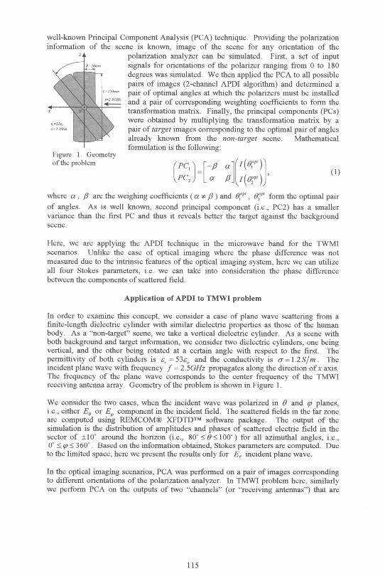
well-known Principal Component Analysis (PCA) technique. Providing the polarizationinformation of the scene is known, image of the scene for any orientation of the
polarization analyzer can be simulated. First, a set of inputsignals for orientations of the polarizer ranging from 0 to 180degrees was simulated. We then applied the PCA to all possiblepairs of images (2-channel APDI algorithm) and determined apair of optimal angles at which the polarizers must be installed
2 and a pair of corresponding weighting coefficients to form thetransformation matrix. Finally, the principal components (PCs)were obtained by multiplying the transformation matrix by apair of target images corresponding to the optimal pair of anglesalready known from the non-target scene. Mathematicalformulation is the following:
Figure 1. Geometryof the problem (Pc, r- al(i(-1)1
LPCYLH a a [(6P)J, (1)where a, /3 are the weighing coefficients (a . /3) and KP, ,'O form the optimal pairof angles. As is well known, second principal component (i.e., PC2) has a smallervariance than the first PC and thus it reveals better the target against the backgroundscene.
Here, we are applying the APDI technique in the microwave band for the TWMIscenarios. Unlike the case of optical imaging where the phase difference was notmeasured due to the intrinsic features of the optical imaging system, here we can utilizeall four Stokes parameters, i.e. we can take into consideration the phase differencebetween the components of scattered field.
Application of APDI to TMWI problem
In order to examine this concept, we consider a case of plane wave scattering from afinite-length dielectric cylinder with similar dielectric properties as those of the humanbody. As a "non-target" scene, we take a vertical dielectric cylinder. As a scene withboth background and target information, we consider two dielectric cylinders, one beingvertical, and the other being rotated at a certain angle with respect to the first. Thepermittivity of both cylinders is e, = 53e0 and the conductivity is cr= 1.2S/m. Theincident plane wave with frequency f = 2.5GHz propagates along the direction ofx axis.The frequency of the plane wave corresponds to the center frequency of the TMWIreceiving antenna array. Geometry ofthe problem is shown in Figure 1.
We consider the two cases, when the incident wave was polarized in 9 and q planes,i.e., either Es or EV component in the incident field. The scattered fields in the far zoneare computed using REMCOMO XFDTDTM software package. The output of thesimulation is the distribution of amplitudes and phases of scattered electric field in thesector of ±10' around the horizon (i.e., 80' <9<100') for all azimuthal angles, i.e.,0' < q. < 360'. Based on the information obtained, Stokes parameters are computed. Dueto the limited space, here we present the results only for E, incident plane wave.
In the optical imaging scenarios, PCA was performed on a pair of images correspondingto different orientations of the polarization analyzer. In TMWI problem here, similarlywe perform PCA on the outputs of two "channels" (or "receiving antennas") that are
115

oriented at angles yr,, gV2 . The outputs of these channels are given as, Channel andChanne4:
Channel, = |E,,e'o cos VI + E5ei¢° sin V/1
Channel2 = IE,,ej'cos*v2 + E5ej¢° sinm 2I (2)
where E6, 0, are the amplitude and the phase of 6 component of the scattered electricfield and E,, (D, are the amplitude and the phase of p component of the scattered fieldwith 0<. y#1, V/2 .180. The PCA is performed on signals, corresponding to all possiblecombinations of angle of orientation of receiving antenna (i.e., yt' and y/2). From thePCA, we find four parameters, i.e. two weighting coefficients a, ,B (also can be called"adaptive" coefficients) and two eigenvalues, which ar all functions of 5v,, and YV2 . Asan "opfimal" pair of angles, we select a pair that corresponds to peak values of theweighting coefficient a. The issue of selecting the optimal coefficients in context ofoptical imaging is discussed in details in [4]. As object (or "target") scenes, we considerthe presence of an additional cylinder rotated relative to the original cylinder by a certainangle. We study the cases when the angle between cylinders is 30' and 60'. For bothorientations of the additional cylinder, we simulate a pair of signals according to Eq. (2),where y/,, Y'2 are taken to be the optimal pair of angles found from the statistics of the"background" object. Then the PC signals are computed according to (1).
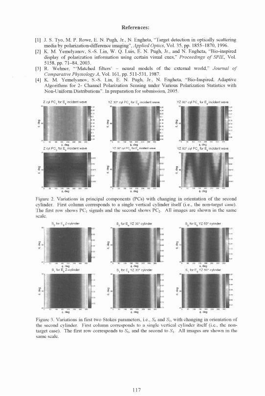
In order to estimate the advantage of using the principal component analysis in thisproblem, we compare changes in the first and second principal components values (i.e.,PC, and PC2) for the two cases of rotated second cylinder. The results are shown inFigure 2. As a benchmark case, we include the PC signals obtained when we apply thesame pair of adaptive coefficients to the signal produced by a vertical cylinder itself(refer to the first column in Figure 2). The variation in the first PC, corresponding to thelargest eigenvalues, is approximately the same for all cases, while the variation in thesecond PC changes significantly when the "target" cylinders are presented. An importantissue we need to address here is whether the use ofjust Stokes parameters is good enoughto identify changes in the scene. In Figure 3 we show the variation of the Stokesparameters with changes in mutual orientation of the cylinders. Although changes in thedistribution of Stokes parameters do take place, it is less significant than that in the onesin the pnncipal components signals (compare Figure 2 and Figure 3). These resultsprovide some evidence that a simple use of Stokes parameters may not surpass theadvantages provided by the APDI algorithm.
Conclusions
The results presented in the paper show a significant potential of APDI algorithm forTMWI applications. As a future work, we plan to apply the proposed method to realimages of inside-the-room scene, which will be obtained using the beam-formingtechniques.
Acknowledgments
This work was supported by DARPA through the Grant MDA972-02-1-0022. Thecontent of the information does not necessarily reflect the position or the policy of theGovernment, and no official endorsement should be inferred
116
References:
[I] J. S. Tyo, M. P. Rowe, E. N. Pugh, Jr., N. Engheta, "Target detection in optically scatteringmedia by polarization-difference imaging", Applied Optics, Vol. 35, pp. 1855-1870, 1996.
[2] K. M. Yemelyanov, S.-S. Lin, W. Q. Luis, E. N. Pugh, Jr., and N. Engheta, "Bio-inspireddisplay of polarization information using certain visual cues," Proceedings of SPIE, Vol.5158, pp. 71-84, 2003.
13] R. Wehner, "'Matched filters' - neural models of the external world," Journal ofComparative Physiology A, Vol. 161, pp. 511-531, 1987.
[4] K. M. Yemelyanov, S.-S. Lin, E. N. Pugh, Jr., N. Engheta, "Bio-Inspired, AdaptiveAlgorithms for 2- Channel Polarization Sensing under Various Polarization Statistics withNon-Uniform Distributions". In preparation for submission, 2005.
Z CYI PC, E incidrnt -we YZ 30' cyl PC, fIr E incident -ove YZ 30° cy PC, to E.ncient.ivdt e
i
0e 09
YZ Eo°c1 PC2 for E
Figure 2. Variations in principal components (PCs) with changing in orientation of the secondcylinder. First column corresponds to a single vertical cylinder itself (i.e., the non-target case).The first row shows PC, signals and the second shows PC2. All images are shown in the samescale.
O for E. Z-"cinder S for E YZ 30° cy1ind., fr E YZ tt' cylinJer
deg5 for E. YZ 30' cAinrder
I.S, tor E_ YZ Eo° cymin.,
Figure 3. Variations in first two Stokes parameters, i.e., S0 and S,, with changing in orientation ofthe second cylinder. First column corresponds to a single vertical cylinder itself (i.e., the non-
target case). The first row corresponds to So, and the second to S,. All images are shown in thesame scale.
117
QIL
5. for E_ Z. wdirer
1
N. (
#uIYZ -20> cy C r, . rn