adaptation to scientific and technical progress of annex ... · the first adaptation of 27 june...
TRANSCRIPT

Adaptation to Scientific and Technical Progress of Annex II Directive 2000/53/EC Contract N°07010401/2007/470145/ATA/G4
Final Report - Amended Final -
Freiburg, 16 January 2008
Öko-Institut e.V. Dr. Joachim Lohse
Stéphanie Zangl
Rita Groß
Carl-Otto Gensch
Fraunhofer IZM Dr. Otmar Deubzer
Öko-Institut e.V. Freiburg Head Office P.O. Box 50 02 40 D-79028 Freiburg Visiting Address Merzhauser Str. 173 D-79100 Freiburg Tel. +49 (0) 761 – 4 52 95-0 Fax +49 (0) 761 – 4 52 95-88 Darmstadt Office Rheinstraße 95 D-64295 Darmstadt Tel. +49 (0) 6151 – 81 91-0 Fax +49 (0) 6151 – 81 91-33 Berlin Office Novalisstraße 10 D-10115 Berlin Tel. +49 (0) 30 – 28 04 86-80 Fax +49 (0) 30 – 28 04 86-88

For the benefit of the environment, this study has been optimized for
double-sided printing.

Adaptation to Scientific and Technical Progress of Annex II Directive 2000/53/EC Final Report
I
Content
1 Background and Objectives................................................................. 6
2 Scope...................................................................................................... 7
3 Evaluation procedure............................................................................ 7
4 Results.................................................................................................... 8 4.1 Overview...........................................................................................................9 4.2 Exemption no. 1 “Steel for machining purposes and galvanised steel
containing up to 0.35% lead by weight” ..........................................................11 4.2.1 Description of requested extension of exemption.......................................11 4.2.2 Summary of justification for exemption.......................................................13 4.2.3 Critical review of data and information given by the applicant or
stakeholders ...............................................................................................16 4.2.4 Final recommendation ................................................................................17 4.2.5 References .................................................................................................18
4.3 Exemption no. 2(a) “Aluminium for machining purposes with a lead content up to 1.5% by weight” ........................................................................18 4.3.1 Description of requested extension of exemption.......................................18 4.3.2 Summary of justification for exemption.......................................................19 4.3.3 Critical review of data and information given by the applicant or
stakeholders ...............................................................................................20 4.3.3.1 Final recommendation ................................................................................21
4.4 Exemption no. 2(b) “Aluminium for machining purposes with a lead content up to 0.4% by weight” ........................................................................21 4.4.1 Description of requested extension of exemption.......................................21 4.4.2 Summary of justification for exemption.......................................................22 4.4.3 Critical review of data and information given by the applicant or
stakeholders ...............................................................................................24 4.4.4 Final recommendation ................................................................................25 4.4.5 References .................................................................................................25
4.5 Exemption no. 3 “Copper alloy containing up to 4% lead by weight” ..............26 4.5.1 Description of requested extension of exemption.......................................26 4.5.2 Summary of justification for exemption.......................................................26 4.5.3 Critical review of data and information given by stakeholders....................28

Final Report Adaptation to Scientific and Technical Progress
of Annex II Directive 2000/53/EC
II
4.5.4 Final recommendation ................................................................................29 4.5.5 References .................................................................................................30
4.6 Exemption no. 4 “Lead-bearing shells and bushes”........................................31 4.6.1 Description of existing exemption and request for extension .....................31 4.6.2 Justification for continued exemption .........................................................31 4.6.3 Critical review .............................................................................................32 4.6.4 Final recommendation ................................................................................34 4.6.5 References .................................................................................................34
4.7 Exemption no. 5 “Lead in Batteries” ...............................................................34 4.7.1 Abbreviations and definitions......................................................................34 4.7.2 Description of exemption ............................................................................34 4.7.3 Criteria for justification of exemption continuation from stakeholders ........35 4.7.4 Critical review of data and information given by stakeholders....................37 4.7.5 Final recommendation ................................................................................38 4.7.6 References exemption 5.............................................................................39
4.8 Exemption no. 6 “Vibration dampers” .............................................................39 4.8.1 Description of requested extension of exemption.......................................39 4.8.2 Summary of justification for exemption.......................................................40 4.8.3 Critical review of data and information given by the applicant or
stakeholders ...............................................................................................40 4.8.4 Final recommendation ................................................................................41 4.8.5 References .................................................................................................41
4.9 Exemption no. 7(b) “Bonding agents for elastomers in powertrain applications containing up to 0.5% lead by weight” ........................................42 4.9.1 Description of requested extension of exemption.......................................42 4.9.2 Summary of justification for exemption.......................................................42 4.9.3 Critical review of data and information given by stakeholders....................42 4.9.4 Final recommendation ................................................................................43
4.10 Exemption no. 8 “Solder in electronic circuit boards and other electric applications” ...................................................................................................45 4.10.1 Description of exemption “Lead in solders in electronic circuit boards
and in other electric applications except on glasses” .................................46 4.10.2 Stakeholders’ criteria for justification of exemption continuation ................48 4.10.3 Critical review of data and information given by stakeholders....................49

Adaptation to Scientific and Technical Progress of Annex II Directive 2000/53/EC Final Report
III
4.10.4 Final recommendation “Lead in solders in electronic circuit boards and in other electric applications except on glasses” .................................56
4.10.5 Description of exemption “Lead in solders used on glasses in other electric applications” ...................................................................................57
4.10.6 Stakeholders’ criteria for justification of exemption continuation and exemption removal .....................................................................................58
4.10.7 Critical review of data and information given by stakeholders....................59 4.10.7.1 Qualification Test Procedure ......................................................................60 4.10.7.2 Further proceeding .....................................................................................61 4.10.8 Final recommendation for all applications of lead covered by
exemption no. 8 ..........................................................................................61 4.10.9 References exemption no. 8.......................................................................63
4.11 Exemption no. 11 “Electrical components which contain lead in a glass or ceramic matrix compound except glass in bulbs and glaze of spark plugs”..............................................................................................................65 4.11.1 Abbreviations and definitions......................................................................65 4.11.2 Description of exemption ............................................................................65 4.11.2.1 Total amounts of lead used in vehicles under exemption 11......................67 4.11.3 Criteria for justification from stakeholders ..................................................69 4.11.4 Critical review of data and information given by stakeholders....................71 4.11.4.1 Thickfilm technology and crosslinks to exemptions in the RoHS
Directive......................................................................................................75 4.11.5 Final recommendation ................................................................................77 4.11.6 References .................................................................................................77
4.12 New request for exemption “Lead in frit glass used in Vacuum Fluorescent Displays” .....................................................................................78 4.12.1 Description of requested exemption ...........................................................78 4.12.2 Justification for new exemption ..................................................................78 4.12.3 Critical Review............................................................................................79 4.12.4 Final recommendation ................................................................................79
4.13 Exemption no. 12 “Pyrotechnic initiators” .......................................................79 4.13.1 Description of existing exemption and request for extension .....................79 4.13.2 Justification for continued exemption .........................................................80 4.13.3 Critical Review............................................................................................81 4.13.4 Final recommendation ................................................................................81

Final Report Adaptation to Scientific and Technical Progress
of Annex II Directive 2000/53/EC
IV
4.13.5 References .................................................................................................81 4.14 Exemption no. 13(b) “Hexavalent chromium in corrosion preventive
coatings related to bolt and nut assemblies for chassis applications”.............82 4.14.1 Description of existing exemption...............................................................82 4.14.2 Justification for continued exemption .........................................................83 4.14.3 Critical Review............................................................................................83 4.14.4 Final recommendation ................................................................................84
4.15 Exemption no. 14 “Absorption refrigerators in motor caravans”......................84 4.15.1 Description of existing exemption...............................................................84 4.15.2 Justification for continued exemption .........................................................85 4.15.3 Critical Review............................................................................................86 4.15.4 Final recommendation ................................................................................87
4.16 Exemption no. 15 “Discharge lamps which contain mercury and instrument panel displays” ..............................................................................88 4.16.1 Description of existing exemption and request for extension .....................88 4.16.2 Justification for continued exemption .........................................................89 4.16.2.1 HID Headlight Lamps .................................................................................89 4.16.2.2 Instrument Panel Displays..........................................................................90 4.16.3 Critical Review............................................................................................90 4.16.4 Final recommendation ................................................................................92 4.16.5 References .................................................................................................92
4.17 Exemption no. 17 “Batteries for electrical vehicles” ........................................92 4.17.1 Description of existing exemption...............................................................92 4.17.2 Justification for (dis)continued exemption ..................................................94 4.17.3 Critical Review............................................................................................95 4.17.4 Final recommendation ................................................................................95
5 Further proceeding ............................................................................. 95
6 Annexes................................................................................................ 96 6.1 Annex I: Questions with regard to exemption no. 3 ........................................96 6.2 Annex II: Questions with regard to exemption no. 6 .......................................96 6.3 Annex III: Questions with regard to exemption no. 7 ......................................97 6.4 Annex IV: Additional information regarding exemption no. 8 ..........................98
6.4.1 Annex IVa: CLEPA comments on lead-free solder use on glasses in other electrical applications of exemption no. 8..........................................98

Adaptation to Scientific and Technical Progress of Annex II Directive 2000/53/EC Final Report
V
6.4.2 Annex IVb: St. Gobain test of indium-containing solders on glasses (exemption 8)............................................................................................101
6.4.3 Annex IVc: Test documents as provided by Antaya .................................102 6.5 Annex V: Additional information regarding exemption no. 11 .......................113 6.6 Annex VII: Questions with regard to exemption no. 17.................................116

Final Report Adaptation to Scientific and Technical Progress
of Annex II Directive 2000/53/EC
6
1 Background and Objectives
Following the requirements of Article 4(2)(a) of Directive 2000/53/EC on end-of-life vehicles (ELV Directive), Member States of the European Union have to ensure that materials and components of vehicles put on the market since 1 July 2003 do not contain lead, mercury, hexavalent chromium and cadmium. A limited number of applications exempted from the provision of this article are listed in Annex II to the Directive, as well as scope and expiry date of the exemption and labelling requirement according to Article 4(2)(b)(iv)1 (if applicable).
Based on Article 4(2)(b), Annex II is to be adapted to scientific and technical progress by the Commission on a regular basis. This is done in order to check whether existing exemptions are still justified with regard to the requirements laid down in Article 4(2)(b)(ii), whether additional exemptions have been proposed on the basis of the same article, and whether exemptions are not justified anymore and need to be deleted from the Annex with regard to Article 4(2)(b)(iii). Furthermore, the adaptation procedure – as necessary – has to establish maximum concentration values up to which the restricted substances shall be tolerated (Article 4(2)(b)(i)) and designate those materials and components that need to be labelled.
With regard to this adaptation procedure, Annex II has already been adapted twice2:
The first adaptation of 27 June 2002 (Commission Decision 2002/525/EC) replaces the original Annex II from Directive 2000/53/EC and provides that cadmium in batteries for electrical vehicles is not put on the market after 31 December 2005.
The second adaptation from 20 September 2005 (Council Decision 2005/673/EC) again replaces the Annex II in force, including new expiry dates for some applications as well as adapted labelling requirements. This amendment also includes new entries, while others have been deleted from the list (depending on whether the use of hazardous substances is avoidable or not).
The latter Decision enumerates four exemptions which need to be examined by the Commission by 1 July 2007 or by end of 2007 respectively with regard to their expiry dates on the basis of an assessment on whether the use of hazardous substances is still unavoidable. Additionally, the Commission receives further requests for exemption based on Article 4(2)(b)(ii) according to which certain materials and components of vehicles shall be exempted from requirement of Article 4(2)(a) if the use of the four restricted heavy metals is unavoidable. These requests also have to be evaluated.
Against this background, the Commission launched a stakeholder consultation which ended 20 December 2006 in order to collect data necessary for the evaluation of the four
1 Article 4(2)(b)(iv) provides that designated materials and components of vehicles that can be stripped before
further treatment have to be labelled or made identifiable by other appropriate means. 2 Additionally the Annex has been amended by Commission Decision 2005/63/EC of 24 January 2005 and
Commission Decision 2005/438/EC of 10 June 2005 by adding the requirement that spare parts put on the market after 1 July 2003 used for vehicles put on the market before that date are exempted from the use restrictions in Article 4(2)(a).

Adaptation to Scientific and Technical Progress of Annex II Directive 2000/53/EC Final Report
7
exemptions mentioned in Decision 2005/673/EC, of one additional request received as well as of the remaining exemptions listed in Annex II.
The objective of the service contract for which the call for tender ENV.G.4/ATA/2007/0004r was launched is thus to provide a clear technical and scientific assessment of the exemptions mentioned above as well as of any new request for exemption.
This final report gives an overview on the results gathered during the evaluation of the exemptions including recommendations on the adaptation of Annex II to scientific and technical progress.
2 Scope
For an overview on the scope of the project, please refer to the interim report published on http://circa.europa.eu/Public/irc/env/elv/library?l=/stakeholder_consultation/evaluation_procedure/reports/interim_report&vm=detailed&sb=Title.
3 Evaluation procedure
The evaluation has been carried out on the basis of the consultation run by the Commission at the end of 2006. Stakeholders were asked to submit comments on certain entries of Annex II:
Exemptions 2(a), 4, 13(b) and 17 all have an expiry date in 2008 and thus received high priority, as the Commission was in the obligation to assess whether these expiry dates have to be reviewed.
For exemption 11 and exemption 15 partly (only for the use of mercury in discharge lamps), the Commission had received information that substitutes were available, and therefore needed to assess whether the exemptions are still justified.
Furthermore, stakeholders were asked to comment on what had been posted as a new exemption request on lead in frit glass used in Vacuum Fluorescent Displays.
Although the consultation document mentions that, according to Article 4(2)(b), Annex II needs to be adapted to scientific and technical progress regularly, and that the objective of the contract also is to assess all entries of Annex II, the section on “consultation of interested parties” does not explicitly ask stakeholders to comment and if necessary justify other entries of Annex II than those listed above.
This has lead to certain confusion among stakeholders when Öko-Institut and Fraunhofer IZM addressed them with questions relating to all entries of Annex II, resulting in a delay with regard to information provision. Some stakeholders claimed that they were not aware of the fact that the whole Annex was undergoing review.

Final Report Adaptation to Scientific and Technical Progress
of Annex II Directive 2000/53/EC
8
Furthermore, in the beginning of the evaluation Öko-Institut and Fraunhofer could only rely on the little information that had been published as a reaction to the consultation (cf. http://circa.europa.eu/Public/irc/env/elv/library?l=/stakeholder_consultation&vm=detailed&sb=Title).
At the beginning of the project, stakeholders were informed proactively by the Commission that an evaluation of Annex II was taking place. Also, Öko-Institut and Fraunhofer IZM had early contacts to associations of automotive industry (inter alia ACEA and CLEPA) and also communicated the objectives of this project.
This situation is reflected in the recommendations included in the next section. For some exemptions an in-depth evaluation could not take place due to a lack of information. E.g. information concerning efficiency and overall environmental relevance of the reduction of hazardous substances in vehicles through revision of Annex II could not be incorporated – although requested by stakeholders and considered useful.
Documentation – made available by stakeholders and not declared as confidential – which has been used for the evaluation is available upon request. Some of it is attached to this report.
Where the contractor felt there were overlapping issues between Annex II ELV Directive and the Annex of the RoHS Directive (both dealing with exemptions from substance restrictions in vehicles respective electrical and electronic equipment [EEE]) possibilities for harmonisation of the wording were mentioned. Although vehicles and EEE are certainly different products (i.e. the use of substances in certain applications is completely different3), some technical specifications remain identical or very similar (e.g. CrVI is used as anti-corrosion protection in both product types) and the wording / scope of exemptions in both Directives should be consistent. This does not mean that the exemption in one Directive automatically leads to an exemption in the other one and vice versa. The RoHS Annex is currently undergoing review and results of both – ELV and RoHS – exemption evaluations should be taken into consideration accordingly.
4 Results
Taking the above mentioned points into consideration, the following section contains evaluation results on the basis of information made available to the contractor. Some information reached the contractor very late in the process and thus could not (fully) be evaluated.
3 E.g. the fact that lead-free solders can be used in electronics covered by the RoHS Directive does not
necessarily mean that they can be used in automotive applications.
Adaptation to Scientific and Technical Progress of Annex II Directive 2000/53/EC Final Report
9
4.1 Overview
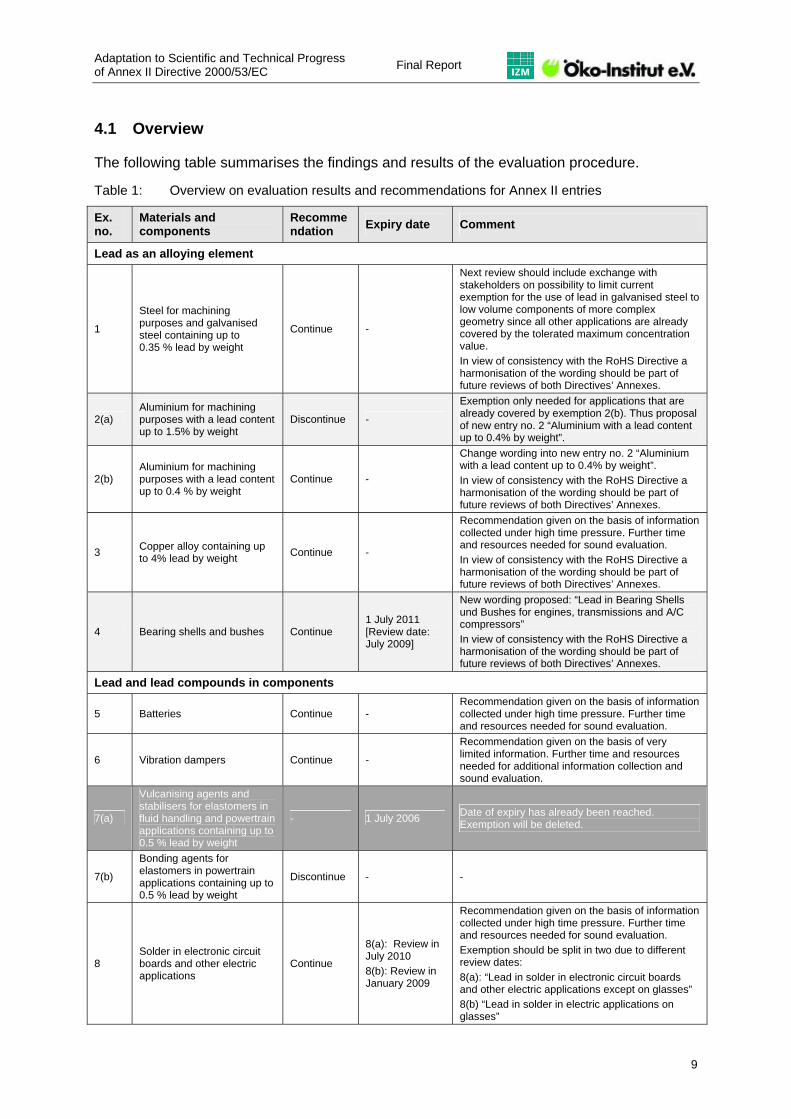
The following table summarises the findings and results of the evaluation procedure.
Table 1: Overview on evaluation results and recommendations for Annex II entries
Ex. no.
Materials and components
Recommendation Expiry date Comment
Lead as an alloying element
1
Steel for machining purposes and galvanised steel containing up to 0.35 % lead by weight
Continue -
Next review should include exchange with stakeholders on possibility to limit current exemption for the use of lead in galvanised steel to low volume components of more complex geometry since all other applications are already covered by the tolerated maximum concentration value. In view of consistency with the RoHS Directive a harmonisation of the wording should be part of future reviews of both Directives’ Annexes.
2(a) Aluminium for machining purposes with a lead content up to 1.5% by weight
Discontinue -
Exemption only needed for applications that are already covered by exemption 2(b). Thus proposal of new entry no. 2 “Aluminium with a lead content up to 0.4% by weight”.
2(b) Aluminium for machining purposes with a lead content up to 0.4 % by weight
Continue -
Change wording into new entry no. 2 “Aluminium with a lead content up to 0.4% by weight”. In view of consistency with the RoHS Directive a harmonisation of the wording should be part of future reviews of both Directives’ Annexes.
3 Copper alloy containing up to 4% lead by weight Continue -
Recommendation given on the basis of information collected under high time pressure. Further time and resources needed for sound evaluation. In view of consistency with the RoHS Directive a harmonisation of the wording should be part of future reviews of both Directives’ Annexes.
4 Bearing shells and bushes Continue 1 July 2011 [Review date: July 2009]
New wording proposed: “Lead in Bearing Shells und Bushes for engines, transmissions and A/C compressors” In view of consistency with the RoHS Directive a harmonisation of the wording should be part of future reviews of both Directives’ Annexes.
Lead and lead compounds in components
5 Batteries Continue - Recommendation given on the basis of information collected under high time pressure. Further time and resources needed for sound evaluation.
6 Vibration dampers Continue -
Recommendation given on the basis of very limited information. Further time and resources needed for additional information collection and sound evaluation.
7(a)
Vulcanising agents and stabilisers for elastomers in fluid handling and powertrain applications containing up to 0.5 % lead by weight
- 1 July 2006 Date of expiry has already been reached. Exemption will be deleted.
7(b)
Bonding agents for elastomers in powertrain applications containing up to 0.5 % lead by weight
Discontinue - -
8 Solder in electronic circuit boards and other electric applications
Continue
8(a): Review in July 2010 8(b): Review in January 2009
Recommendation given on the basis of information collected under high time pressure. Further time and resources needed for sound evaluation. Exemption should be split in two due to different review dates: 8(a): “Lead in solder in electronic circuit boards and other electric applications except on glasses” 8(b) “Lead in solder in electric applications on glasses”
Final Report Adaptation to Scientific and Technical Progress
of Annex II Directive 2000/53/EC
10
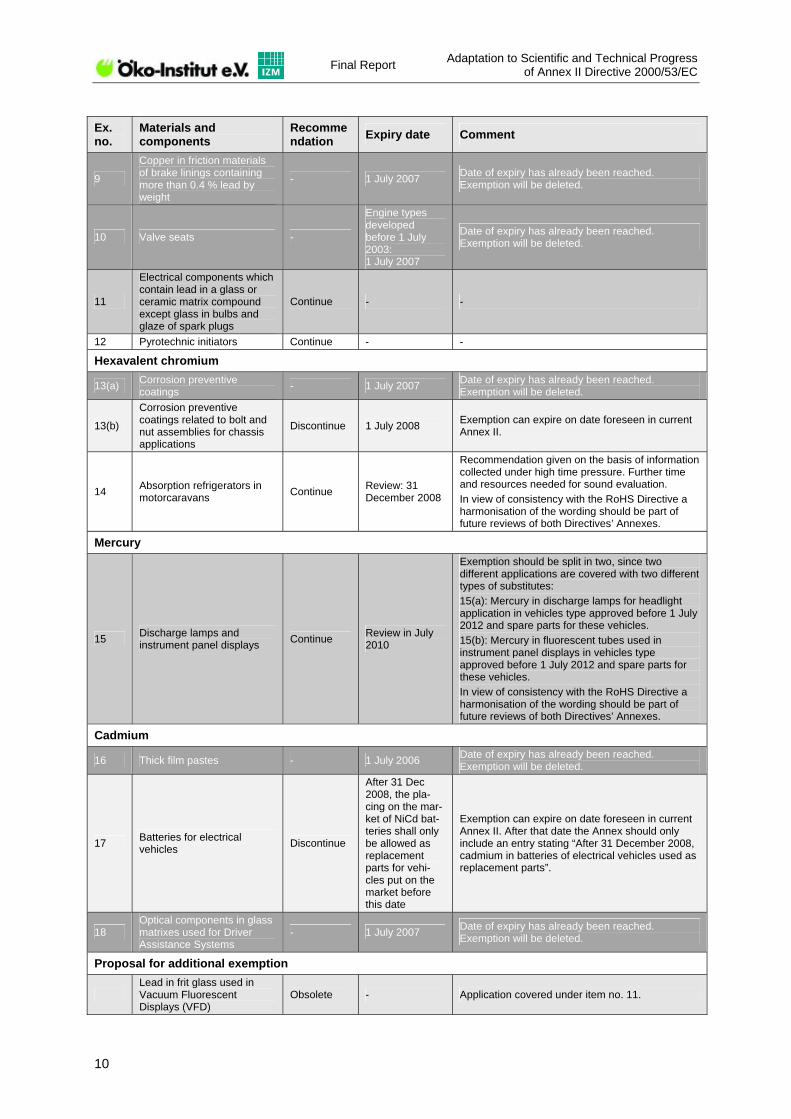
Ex. no.
Materials and components
Recommendation Expiry date Comment
9
Copper in friction materials of brake linings containing more than 0.4 % lead by weight
- 1 July 2007 Date of expiry has already been reached. Exemption will be deleted.
10 Valve seats -
Engine types developed before 1 July 2003: 1 July 2007
Date of expiry has already been reached. Exemption will be deleted.
11
Electrical components which contain lead in a glass or ceramic matrix compound except glass in bulbs and glaze of spark plugs
Continue - -
12 Pyrotechnic initiators Continue - -
Hexavalent chromium
13(a) Corrosion preventive coatings - 1 July 2007 Date of expiry has already been reached.
Exemption will be deleted.
13(b)
Corrosion preventive coatings related to bolt and nut assemblies for chassis applications
Discontinue 1 July 2008 Exemption can expire on date foreseen in current Annex II.
14 Absorption refrigerators in motorcaravans Continue Review: 31
December 2008
Recommendation given on the basis of information collected under high time pressure. Further time and resources needed for sound evaluation. In view of consistency with the RoHS Directive a harmonisation of the wording should be part of future reviews of both Directives’ Annexes.
Mercury
15 Discharge lamps and instrument panel displays Continue Review in July
2010
Exemption should be split in two, since two different applications are covered with two different types of substitutes: 15(a): Mercury in discharge lamps for headlight application in vehicles type approved before 1 July 2012 and spare parts for these vehicles. 15(b): Mercury in fluorescent tubes used in instrument panel displays in vehicles type approved before 1 July 2012 and spare parts for these vehicles. In view of consistency with the RoHS Directive a harmonisation of the wording should be part of future reviews of both Directives’ Annexes.
Cadmium
16 Thick film pastes - 1 July 2006 Date of expiry has already been reached. Exemption will be deleted.
17 Batteries for electrical vehicles Discontinue
After 31 Dec 2008, the pla-cing on the mar-ket of NiCd bat-teries shall only be allowed as replacement parts for vehi-cles put on the market before this date
Exemption can expire on date foreseen in current Annex II. After that date the Annex should only include an entry stating “After 31 December 2008, cadmium in batteries of electrical vehicles used as replacement parts”.
18 Optical components in glass matrixes used for Driver Assistance Systems
- 1 July 2007 Date of expiry has already been reached. Exemption will be deleted.
Proposal for additional exemption
Lead in frit glass used in Vacuum Fluorescent Displays (VFD)
Obsolete - Application covered under item no. 11.

Adaptation to Scientific and Technical Progress of Annex II Directive 2000/53/EC Final Report
11
4.2 Exemption no. 1 “Steel for machining purposes and galvanised steel containing up to 0.35% lead by weight”
4.2.1 Description of requested extension of exemption
Exemption 1 comprises both the addition of lead to steel for machining purposes and the use of lead for the production of galvanised steel.
Stakeholders from the Iron and Steel Industries (represented by the European Confederation of Iron and Steel Industries – Eurofer), the European General Galvanizers Association (EGGA) and the automotive industry request an extension of exemption 1 “Steel for machining purposes and galvanised steel containing up to 0.35% lead by weight”.
Steel for machining purposes:
Lead is used in steel for an improved machinability. By the addition of lead better chip fracturing, automation of the production process, high cutting speed and federates (low cycle times), longer tool life, better surface finish and more accurate dimension control can be achieved.
Two different leaded steel grades are being distinguished:
a) Low carbon free-cutting steels (aluminium free);
b) Carbon and low alloy steels (aluminium killed).
Free-cutting steels provide optimum free-machining performance with comparatively low mechanical strength. These steels are used where their strength levels satisfy the final component mechanical requirements and there is a high requirement for machinability. If greater mechanical strength is required, a carbon or alloy grade may need to be specified. If machining is also required on these components, the best method of aiding machining and hence reducing financial and energy costs can be found through the addition of lead.
The main production countries of leaded steels are UK, Germany, France and Spain. The total production volume of leaded steel in the EU is estimated to be 1.3 Mt per year.
Leaded steel is used in a broad variety of applications in vehicles according to figures provided by the automotive industry. For example, the International Material Data System (IMDS) lists up to 25’000 steel parts containing lead. Leaded steel is used, among others, in the following applications: bolts, screws, nuts, hollow screws, valve pins, spring guides, valve pistons, valve seats, sleeves, piston rods, magnet/pole cores, solenoid, bushings, housings, distance pieces, bleed screws, axles, shafts, stubs, sockets, locks, brackets, rotors, etc. Most of these parts are used in environmental-/safety critical systems (e.g. brake, lighting, fuel, restraint, engine).
The amount of lead in machining steel per vehicle is estimated to range from 10 to 25 g. So the total lead amount from these kinds of applications in vehicles produced in Europe is between 160 and 400 t/y.

Final Report Adaptation to Scientific and Technical Progress
of Annex II Directive 2000/53/EC
12
Galvanised steel
General (batch) galvanizing is the immersion of fabricated steel articles into a bath of molten zinc, containing a certain amount of lead, to apply a zinc coating that is metallurgically bonded to the steel. The coating is specified according to EN ISO 1461 (1999).
Lead has no beneficial (or adverse) effect on the coated product, but has important functions in the galvanizing process:
Fluidity – optimal drainage reduces excess zinc on the product (eco-efficiency);
Ease of drossing – to aid recycling;
Avoidance of “floating dross” during galvanizing of complex geometries which may lead to adverse surface finish;
Protect kettle from uneven heat distribution from burners – preventing dangerous “run-outs” of molten zinc.
The extents to which each of these factors is important vary according to the nature of the component to be coated; the technical features of the plant (often related to the age of the plant) and the type of work that is processed by the plant (range of work).
Lead can be introduced to the zinc bath in three ways:
Use of Z5 zinc grades (this way is declining);
Use of recycled zinc;
Small, controlled, additions of lead ingots to baths of Z1 zinc grades.
The maximum content of lead in primary (not recycled) zinc is defined in EN 1179:
EN 1179 Grade Max lead content Z1 (Special High Grade) 0.003% Z2 0.005% Z3 0.03% Z4 0.45% Z5 1.4%
The maximum lead content of recycled zinc is defined by EN 13283:2002. The standard cites 3 grades of secondary zinc- ZSA; ZS1; ZS2 with maximum lead contents of 1.3%; 1.3% and 1.5%, respectively.
Lead has low solubility in the zinc-iron alloys that are formed during the galvanizing reaction. Hence, the quantity of lead present in the coating is normally significantly lower (typically 50%) than the lead present in the process bath (see Table 2 and Table 3). For a given bath composition, the variations in lead concentration in the coating are mainly dependent on steel type (reactivity with molten zinc). As shown in Table 3, lead is alloyed in the coating at levels up to 0.7%.

Adaptation to Scientific and Technical Progress of Annex II Directive 2000/53/EC Final Report
13
Table 2: Composition of galvanizing bath
Plant Pb (%) Sn (%) Al (%) 1 1.017 0.203 - 2 1.047 0.478 0.037
Table 3: Concentration of lead in coatinga)
Steel type Plant Dipping time (min) Pb(%) Sn (%) Al (%)
5 0.456 0.076 - 1
9 0.383 0.058 - 5 0.351 0.193 0.068 A
2 9 0.381 0.195 0.095 5 0.697 0.109 -
1 9 0.728 0.110 - 5 0.477 0.275 0.084
B 2
9 0.534 0.233 0.110 5 0.380 0.073 -
1 9 0.315 0.059 - 5 0.630 0.367 0.084 C
2 9 0.521 0.283 0.086
a) Lead concentrations in an automobile component galvanized in these baths will be lower
General galvanized automotive components are used in applications such as full chassis to engine cradles, suspension arms, etc. Advantages of general galvanized components include:
Highly durable corrosion protection;
Resistance to stone chipping/mechanical damage;
Increased durability allowing lighter steel sections;
Alternative to coatings containing hexavalent chromium;
Recyclable within existing steel recycling circuit.
General galvanizing is used in a wide range of industries. No specific data exists on the volume of automotive applications. The European General Galvanizers Association (EGGA) estimates that the volume used in applications within the scope of the ELV Directive is approximately 100’000 tonnes of steel.
4.2.2 Summary of justification for exemption
Steel for machining purposes
The justification for the continued exemption can be summarised as follows: “All currently identified alternatives to lead as a machinability enhancer in steel have been formally

Final Report Adaptation to Scientific and Technical Progress
of Annex II Directive 2000/53/EC
14
assessed without identifying any addition that effectively replaces lead in all respects. Lead-free alternatives may show acceptable results in single machinability test, but the overall performance of the lead-free steels is worse than that of leaded steel. If a variety of machining operations is required or if deep drilling of material is required, lead is still considered the best machinability enhancer in an industrial production.
Customer demand supports the view that leaded steels are required rather than the alternatives which are currently offered by European steel manufacturers”.
Reference is made by the steel industry to different reports investigating the machinability of lead-free steel alloys:
The University of Pittsburgh had developed a non-leaded low carbon free cutting steel (1215) containing 0.04-0.08% tin which they claimed can replace leaded free cutting steel (12L14). A range of machinability tests was undertaken with tin treated steel in order to investigate these claims (Bateson, P.H. & Reynolds, P.E., 1999). The results of these tests indicated that tin treated free-cutting steels showed less favourable results with regard to the different aspects on machinability than leaded steels. It was concluded that tin cannot replace lead in free cutting steels.
The European steelmakers and component manufacturers formed a collaborative research project funded by the European Coal & Steel Research (ECSC) to evaluate potential alternatives to lead for low carbon free cutting and carbon/alloy grades.
The final report of this project summarises the results of machinability tests conducted with different lead-treated and lead-free steel alloys. These machinability tests included measurement of tool life, tool wear, surface finish, chip form, tool force and tool temperature. The steel grades selected for these tests were free-cutting steels (11SMn30), steels for hardening and tempering (C45) and case hardening steels (16MnCr5) with the following machinability enhancing additions:
Lead, bismuth, increased sulphur (with and without tellurium), tin (with low and high copper), phosphorus and calcium.
The general conclusion of these tests is that leaded steels showed the best performance in tests at lower cutting speeds with high speed steel tools and in deep hole drilling. Non-leaded alternative grades generally gave poorer chip form and surface finish. It was shown that of the alternatives bismuth is able to substitute for lead under certain conditions, although the cost of the addition may make it uneconomic, particularly for large scale application. Furthermore, the hot workability of bismuth steels is reduced compared to leaded steels. Hot workability is a fundamental requirement for the steel production.
This parameter is of significance when the steel is being rolled to the required size for a customer from a piece with a larger (as-cast) cross sectional area. The reduced hot-workability of bismuth steels effectively means that it is significantly harder for a steel roller to produce a bar with the same machining properties and surface integrity if the steel obtains its machining properties through bismuth rather than lead.

Adaptation to Scientific and Technical Progress of Annex II Directive 2000/53/EC Final Report
15
It can be expected that there would be a higher energy cost associated with bismuth as well as potentially higher rejections (waste).
Although the machining properties of bismuth treated steels approach those of lead treated steels for certain machining operations, in the majority of machining operations lead remains the most effective machinability additive through its combination of machining characteristics.
It was further concluded in the report that calcium can substitute lead in C45 steels for use at higher cutting speeds. However, calcium treated steels have higher cutting forces, poorer chip form and have their best performance limited to a narrower range of machining speeds in comparison with the leaded product. It is highly likely that a variety of machining operations are required for many automotive components, such that the more limited benefits of calcium treated grades may not be able to match the benefits of leaded grades in many instances.
Steels containing tin generally did not show good performance in the machinability tests and thus, was not considered as a suitable replacement for lead in steel.
Galvanised steel
With regard to galvanised steel two different application areas can be distinguished:
1. High volume under-body components with a simple geometry for drainage account for approximately 95% of the volume of general galvanized components used in automotive applications. These components are mainly produced by specialist galvanizers in dedicated facilities that have been optimised to the specific components directed towards that plant. By a combination of engineering solutions (to drossing and bath heating) and alternative alloys (e.g., bismuth for fluidity) these plants were able to eliminate additions of lead and to meet the requirement of <0.1% Pb in the coating.
2. In contrast, low volume components of more complex geometry require being processed in general galvanizing plants. These components include hollow parts and require centrifuge galvanizing (such as those with threads/moving parts, e.g. door hinges for specialist vehicles or crash boxes). For components processed in these plants, the presence of lead is currently not avoidable and could not be reduced to meet the 0.1% lead threshold.
Research is ongoing within the industry to develop new zinc-based alloys for general galvanizing. Principal research goals are (i) more zinc-efficient coatings (thinner coatings regardless of steel type) and (ii) coatings of more consistent appearance and surface finish. These goals are accompanied with a desire to reduce the presence of hazardous substances, including lead.
Due to the fact that current lead prices are higher than those of zinc, there is no economic advantage to intentionally add lead to a galvanizing bath where it is not technically required.
In addition to the technical viability, stakeholders state that there are some important consequences of premature removal of the exemption:
Final Report Adaptation to Scientific and Technical Progress
of Annex II Directive 2000/53/EC
16
Requirements to lower lead levels will result in reduced use of recycled zinc (remelt). The galvanizing industry is the sole outlet for remelt zinc (from roofing applications and remelt of zinc entrained in galvanizers’ ashes). Reduced values for remelt zinc will also adversely affect the economic viability of recycling of galvanizers’ ashes and dross.
Less than optimal drainage can increase zinc use on the component beyond that which is required for its protection.
Bismuth is discussed as a possible substitute for lead; however bismuth is a co-product of lead production. There is currently no primary production of bismuth and its availability to meet the needs of all replacements for lead in industry has been questioned.
Low volume components that do not justify dedicated coating facilities would require transportation (if technically feasible in alternative plants) by road to alternative facilities. By retaining the exemption, the automotive industry will have possibility to utilise the local facilities provided by the industry’s 850 plants in Europe.
Any action to discourage use of galvanized coatings for components can lead to their replacement with alternatives with higher life cycle energy and that are not fully recyclable.
In automotive applications, the coating is mainly employed for its robustness (e.g., stone chipping resistance) and corrosion of the surface is minimal with most of the coating remaining at end of life. The lead in a galvanized coating is alloyed as it is in free-machining steels. There is no preferential release of lead although it is clear that very small quantities of lead may be dispersed if the coating is damaged. According to stakeholders, release to the environment during service life is insignificant. Further, the “exposed” components are typically those high volume components that are already meeting the 0.1% limit. The components for which the exemption is required are typically those that are not exposed to higher levels of corrosion (e.g. hinges).
Environmental relevance
Regarding the environmental relevance of lead in steel during recycling of end-of life vehicles, the majority of the leaded steel parts end up in the metal scrap fraction which is sent to electric arc furnaces (EAF). There, most of the lead is extracted into the off-gas and is captured in dust filters of the off-gas cleaning system. The captured dust is then transferred together with zinc to recycling facilities where lead is won back.
Recent increases in zinc prices have reinforced the economic viability of the recovery of these dusts.
4.2.3 Critical review of data and information given by the applicant or stakeholders
Evaluating the above-mentioned arguments the following can be concluded:
With regard to steel for machining purposes, lead-free alternatives are available providing comparable results to leaded steel in single machinability tests (e.g. bismuth or calcium

Adaptation to Scientific and Technical Progress of Annex II Directive 2000/53/EC Final Report
17
treated steels). However, steels used in the automotive industry go through a variety of machining operations. Thus, the overall performance of steels in the various machinability tests (chip form, tool life and wear, surface finish, tool force, hot workability, deep drilling, etc.) need to be considered. A good machinability of steel is not only economically relevant, but also important from an environmental point of view as a reduced machinability may lead to an increased energy demand during the production process. Comprehensive data were submitted by stakeholders indicating that lead-free alternatives still not show a comparable overall performance in the machinability test to leaded steels.
Although the machining properties of bismuth treated steels approach those of lead treated steels for certain machining operations, its poorer hot workability is considered as significant disadvantage because hot workability is a fundamental requirement for the steel production. Bismuth is mainly produced as by-product of other metals among others bismuth sources are by-products associated with lead mining. There is currently no primary production of bismuth and its availability to meet the needs of all replacements for lead in industry has been questioned. Considering these facts a substitution of lead to bismuth seems questionable both from an economic and environmental point of view.
Calcium treated steels may substitute leaded steels in various applications, however a general substitution does not seem possible at the moment because calcium treated steels have their best performance limited to a narrower range of machining speeds in comparison with the leaded grades.
Regarding galvanised steel stakeholders demonstrated that approximately 95% of the volume of general galvanized components used in automotive applications are under-body components that meet the tolerated maximum concentration value of <0.1% Pb in the coating. Only for the galvanization of low volume components of more complex geometry (e.g. door hinges for specialist vehicles or crash boxes) the presence of lead in the galvanising bath is necessary to ensure optimal drainage of excess zinc from the galvanised product and the quality of surface finish.
From this conclusion it can be derived that the exemption for lead up to 0,35% by weight as an alloying element in galvanised steel could be limited to low volume components. However, this would require another time consuming exchange with the respective stakeholders in order to make sure that the new wording reflects the technical status quo. This was not possible within the time constraints of the present evaluation.
The steel industry pointed out that the biggest part of leaded steel ends up as scrap in electric arc furnaces (EAF) where most of the lead is extracted into the off-gas and then captured in the dust filters of the off-gas cleaning system. Due to increased prices for heavy metals, the predominant part of lead and zinc captured in the dust filters is transferred to recycling facilities where lead and zinc are won back.
4.2.4 Final recommendation
The stakeholders provided plausible information on the necessity of lead in steel for machining purposes and in galvanized steel. Lead-free steel grades are available, but still show a significantly worse overall performance in machinability compared to leaded steels.

Final Report Adaptation to Scientific and Technical Progress
of Annex II Directive 2000/53/EC
18
Based on the available information it can be concluded that the use of lead in steel for machining purposes and in galvanized steel at the current state of the art is not avoidable.
It is hence recommended to continue the exemption without any changes in the wording until the next review of the ELV Directive’s Annex II. This next review should include an exchange with stakeholders on the possibility to limit the current exemption for the use of lead up to 0,35% by weight as an alloying element in galvanised steel to low volume components of more complex geometry since all other applications are already covered by the tolerated maximum concentration value. It should be aimed at either getting a comprehensive list of applications for galvanised steel that need an exemption or restrict the scope of the current exemption by rewording the exemption specifying what exact types of galvanised steel components are included.
In view of consistency in environmental legislation, the contractor would like to remark that the RoHS Directive’s Annex also includes an exemption for the use of lead up to 0.35% in steel (entry no. 6). Currently, the wording of both exemptions is consistent. For future reviews of exemptions under both Directives, a harmonisation of the wording reflecting similar or identical technical specifications should be taken care of.
4.2.5 References
[1] Bateson, P.H. & Reynolds, P.E. (1999); Machinability evaluation of 1215 steel containing tin; British Steel Limited, Swinden Technology Centre, Moorgate, Rotherham, UK; Report No. SL/MA/R/S2916/16/99/D
[2] Reynolds, P.E. et al. (2005); Technically and commercially viable alternatives to lead as machinability enhancers in steel used for automotive components manufacture; European Commission: Technical Steel Research, EUR21912En
[3] Ellis, A. et al. (1998); Machinable engineering steels for the future; Corus Engineering Steels Technical Paper Prod/M3
4.3 Exemption no. 2(a) “Aluminium for machining purposes with a lead content up to 1.5% by weight”
4.3.1 Description of requested extension of exemption
Leaded aluminium alloys are widely used for automotive applications. In general, two different types need to be distinguished:
1) Aluminium alloys where lead is intentionally added for improved machinability.
2) Aluminium alloys that contain lead unintentionally due to their production from scrap metal.

Adaptation to Scientific and Technical Progress of Annex II Directive 2000/53/EC Final Report
19
Subject of this exemption 2(a) is exclusively the first type where lead is deliberately added to aluminium alloys for improved machinability (the second type of alloys being covered by exemption 2(b)).
Currently, the maximum allowed concentration of lead in aluminium alloys for machining purposes is 1.5% by weight. The expiry date for this exemption is 1 July 2008.
Typical uses for aluminium alloys are automotive transmission valves, cylinders and pistons for brake systems or for air conditioning systems, as well as applications in steering systems and in the chassis (e.g. steering knuckles). Aluminium alloys for machining purposes are covered by specific EN standards which define the composition of the different alloys.
In the previous evaluation by Ökopol (2001) that was conducted to provide the Commission with technical information in view of an earlier adaptation of Annex II ELV Directive, it was concluded that from a technical point of view phase-out of (intentionally added) leaded aluminium alloys would be possible by 2005. In the evaluation it was stated that possible routes are either a full renunciation to lead without using substitutes requiring far reaching changes in the production process, or the substitution by tin and/or bismuth. However, it was also mentioned that safety aspects are an important factor to be considered with regard to the timeframe which is needed for the phase out.
Due to its expiry date, exemption 2(a) was part of the stakeholder consultation in 2006. In that context, ALERIS Aluminium (a manufacturer of aluminium products) and FTE automotive GmbH (manufacturer of hydraulic brake and clutch systems) submitted indepen-dently of each other requests for an extension of exemption 2(a) for aluminium alloys with intentionally added lead for the application in brake and clutch systems. FTE automotive GmbH proposes an adjustment of the maximum lead concentration in aluminium alloys from the present value of 1.5% to a new value of 0.7% lead by weight.
No other stakeholder comments requesting an extension of the current exemption for further applications in the scope of exemption 2(a) were received.
4.3.2 Summary of justification for exemption
The stakeholders justify their request for an extension of exemption 2(a) as follows:
The surfaces of aluminium parts are usually finished anodized for functional reasons since anodizing increases corrosion resistance and wear resistance. The function of lead in the described application is the higher resistivity of leaded aluminium alloys compared to tin or bismuth containing aluminium alloys against pitting corrosion in brake and clutch systems: at higher temperatures (>120°C) the adhesion of the anodised coating to the base material of lead-free alloys (e.g. tin and/or bismuth alloys) is stated to be negatively impaired in the presence of certain media like brake fluid. Brake fluid is not stable above 120°C, but degrades into acid components. According to test results provided by stakeholders, these components can attack the anodising surface layer of tin and bismuth containing aluminium alloys leading to pitting corrosion. This phenomenon is observed for lead-free and low-lead aluminium alloys. A certain lead content in aluminium alloys improves both layer adhesion

Final Report Adaptation to Scientific and Technical Progress
of Annex II Directive 2000/53/EC
20
and layer quality. However, the two stakeholders give different figures for the required lead contents in aluminium alloys to prevent the named pitting corrosion: Aleris Aluminium promotes the use of aluminium alloys containing 0.3% lead by weight, whereas FTE automotive deem a higher lead content of 0.7% by weight to be necessary.
Stakeholders have furthermore submitted the comment that “the lead reduction to the 2008 target <0.4 weight-% lead in aluminium is in full progress. Some validation tests especially for components which interact with media like brake fluid and special fluids are not completely finished.”
4.3.3 Critical review of data and information given by the applicant or stakeholders
Stakeholders from automotive industry (represented by ACEA, JAMA, KAMA, CCFA, VDA, CLEPA, GM, SMMT) provided information on the replacement of lead containing aluminium alloys during the other 2006 stakeholder consultation on a possible amendment of Annex II (Issue of certain spare parts for vehicles put on the market after 1 July 2003)4. According to the provided information, lead-free aluminium alloys can be incorporated into vehicles provided that design changes are realised, i.e. the dimension or shape of the aluminium alloy part itself or of parts in the surrounding areas need to be adapted. This means that the replacement of lead containing aluminium parts is possible for new developments because in new vehicles the redevelopments and dimensional changes of the parts are feasible. By contrast, lead containing aluminium parts in already running vehicles can not be replaced by lead-free spare parts because the required design changes are not practicable.
In addition, in the context of the last consultation relevant to this project, the automotive industry (represented by ACEA, JAMA, KAMA, CLEPA) submitted a proposal for an Annex II revision stating that the automotive industry accepts the expiry date of exemption 2(a) and does thus not request an extension.
Therefore, it can be concluded that there is no need for an extension of exemption 2(a) except for the requested application in brake and clutch systems.
With regard to the application of aluminium parts in brake and clutch systems, the applicants provided test results indicating that lead-free aluminium parts containing tin or bismuth are not as resistant to pitting corrosion by contact with brake fluid as lead containing aluminium parts.
After consultation with representatives of the automotive industry during the course of the present evaluation, they state that the automotive industry supports an extension of exemption 2(a) for brake and clutch systems, however they consider a maximum level of up to 0.4% lead by weight as sufficient since most of the suppliers of brake and clutch systems are able to provide respective aluminium parts with maximum lead levels of up to 0.4%. A maximum lead level of up to 0.7% as requested by FTE automotive is not deemed necessary by other suppliers of brake and clutch systems.
4 Cf. http://circa.europa.eu/Public/irc/env/elv/library?l=/stakeholder_consultation_1&vm=detailed&sb=Title
Adaptation to Scientific and Technical Progress of Annex II Directive 2000/53/EC Final Report
21
4.3.3.1 Final recommendation
Taking the provided information into account, the requested exemption for the application of leaded aluminium alloys in brake and clutch systems seems to be justified especially since safety related parts are concerned. Lead-free alternatives containing tin or bismuth were shown to be less appropriate for the use in brake and clutch systems than aluminium alloys containing a certain amount of lead. Due to the fact that the majority of the brake and clutch suppliers are able to provide respective aluminium parts with maximum lead contents of 0.4% by weight, a maximum lead content of up to 0.7% does not seem to be justified.
Aluminium alloys for machining purposes containing lead up to 0.4% by weight are covered by exemption 2(b). Thus, the application of aluminium alloys containing lead up to 0.4% in brake and clutch systems is covered by exemption 2(b). It is therefore recommended to delete the present exemption 2(a) from Annex II of the ELV Directive by 1 July 2008 leaving exemption 2(b) for aluminium alloys containing lead up to 0.4%. It is further proposed to change the wording of exemption 2(b): By deletion of the wording “for machining purposes” exemption 2(b) would not differentiate between intentionally and unintentionally added lead and would thus also cover applications formerly covered by exemption 2(a). For details please refer to the following chapter concerning exemption 2(b).
4.4 Exemption no. 2(b) “Aluminium for machining purposes with a lead content up to 0.4% by weight”
4.4.1 Description of requested extension of exemption
As described in section 4.3, two types of leaded aluminium alloys are distinguished:
1) Aluminium alloys where lead is intentionally added for improved machinability.
2) Aluminium alloys that contain lead unintentionally due to their production from scrap metal.
Exemption 2(b) was initially meant to cover exclusively the second type where lead is unintentionally contained in aluminium alloys (the first type of alloys being covered by exemption 2(a)).
Aluminium produced from recycled scrap metal may unintentionally contain lead. The lead may have been added to the scrap stream over years through not accurately separated wheel rims, aluminium for machining purposes, lead from batteries, and other lead-containing applications. Thus, lead is included in the scrap flow as an impurity which cannot be separated during the scrap process phase. Lead is neither necessary to attain specific properties, nor does the contained lead harm the properties of aluminium alloys as long as its quantity stays within the limits set by European standards5.
5 European standard EN 1706 sets standards for a great number of aluminium alloys and specifies different
limits for lead.
Final Report Adaptation to Scientific and Technical Progress
of Annex II Directive 2000/53/EC
22
In particular, aluminium foundry alloys made from scrap and the products produced from these alloys may contain lead impurities e.g. cylinder heads, engine blocks, gear boxes, water pump housings, etc.
The Organisation of European Aluminium Refiners and Remelters (OEA) and the European Aluminium Association (EAA) request a general exemption of up to 0.4% for the unintentional content of lead in aluminium alloys, and they ask for a deletion of the words “for machining purposes” in entry 2(b) of Annex II. The proposed new wording of exemption 2(b) would read “aluminium with a lead content up to 0.4% by weight”. This request is supported by the automotive industry.
4.4.2 Summary of justification for exemption
The aluminium industry gives the following reasons for a rewording of exemption 2(b):
Before the revision of Annex II through Decision 2002/525/EC, Annex II contained a general exemption of up to 0.4% for an unintentional lead content in aluminium alloys. The 0.4% general exemption was still included in Annex II after Decision 2002/525/EC, albeit no longer in the actual table but in a footnote claiming that "a maximum concentration value up to 0.4% by weight of lead in aluminium shall also be tolerated provided it is not intentionally introduced". The reference to the general exemption was finally deleted with the Council Decision dated 20 September 2005. A scientific justification of the deletion was not given.
Exemption 2(b) in its current state allows a maximum lead concentration in aluminium of up to 0.4%; however, the exemption is limited to “aluminium for machining purposes” only. This means that aluminium alloys for non-machining purposes (e.g. casting alloys) are not covered by this exemption and thus need to comply with the allowed maximum lead concentration value of 0.1% (as specified in footnote 1 to ELV Annex II).
Despite the fact that aluminium casting alloys are also machined after the casting process (e.g. in order to get even areas for contact with other parts, to make holes for bolts, to machining canals for sealing, etc.), the casting alloys are usually not considered as “aluminium for machining purposes” since aluminium for machining purposes is covered by specific EN standards. Casting alloys contain lead only unintentionally due to their production from scrap metal. Lead is not needed in aluminium castings to attain specific alloy properties or to provide a better machinability.
Aluminium scrap from used products, mainly automobiles, contains a certain basic level of lead which comes from manifold sources. In the EU currently ca. 2.7 million tonnes of aluminium casting alloys are annually produced from scrap. Around 70% of these alloys are used to produce castings for automotive applications. The most important applications are cylinder heads, engine blocks and gear houses. Aluminium casting alloys and their products may unintentionally contain lead as an impurity. The lead may have been added to the scrap through not accurately separated wheel rims, aluminium for machining purposes, lead from

Adaptation to Scientific and Technical Progress of Annex II Directive 2000/53/EC Final Report
23
batteries, and other lead-containing applications. The average total lead content of these casting alloys is around 0.18-0.2%. The total quantity of lead, contained in these aluminium casting alloys is between 2’500 and 2’900 tonnes.
The average content of aluminium castings in European automobiles is around 70 kg per vehicle. Estimating an average lead content of 0.18-0.2%, the average lead content in aluminium casting alloys in a single automobile is between 0.13 kg and 0.14 kg.
At the end of their service life, the applications like cylinder heads, gear boxes, etc. are dismantled, recovered and recycled, and the lead that is contained in the aluminium casting alloys re-enters the new circle.
As mentioned before, aluminium casting alloys would have to comply with the allowed lead concentration value of 0.1% (as specified in Footnote 1 to Annex II), if castings were not included in exemption 2(b) of Annex II.
There are two theoretical options to reduce the lead content in aluminium alloys in order to achieve the 0.1% limit:
a) Removal of lead from Aluminium by metallurgical processes
b) Dilution of scrap with primary Aluminium
Removal of lead from Aluminium by metallurgical processes
According to the European Aluminium Association (EAA) and the Organisation of European Aluminium Refiners and Remelters (OEA) the removal of lead from aluminium by a metallurgical process is technically not yet feasible on a grand scale. Research on the removal of lead from aluminium e.g. by melt purification is currently being conducted. The research activities are still in an early stage and have not yet produced practicable solutions for industrial applications.
Dilution of scrap with primary Aluminium
Theoretically, the lead content of scrap can be reduced by diluting the melt with primary aluminium. To reduce the lead content from 0.35% to 0.1%, it would be necessary to add 2.5 tonnes of primary aluminium to 1 tonne of recycled aluminium. Even with an average lead content of 0.2% in 55% of all aluminium casting alloys, in Europe an additional amount of ca. 1.1 million tonnes of primary metal would be necessary in order to reduce the lead content to 0.1% in aluminium casting alloys.
According to EAA/OEA the primary metal needed for diluting is not available, because the primary aluminium industry is already running at full capacity. It would take years until additional capacities could deliver the material.
Currently, the global aluminium production is around 200’000 tonnes lower than the demand. New primary aluminium capacities, which are in the planning phase, are needed to supply the growing global demand for aluminium (average global increase annually 3.4%).

Final Report Adaptation to Scientific and Technical Progress
of Annex II Directive 2000/53/EC
24
From an environmental point of view the dilution of scrap with primary aluminium is not considered to be a reasonable option because the quantity of energy needed to produce primary metal is 95% higher than the amount of energy needed to produce casting alloys from scrap (EAA Energy figures primary recycling).
EAA/OEA state that there is no risk to the environment and/or human health from aluminium with a lead content up to 0.4% by weight. It is argued that lead exists as an impurity in aluminium. Lead is present in ‘solid solution’ in the metallic grid or as dispersed constituents of a size smaller than 1μm. As aluminium does not corrode under normal conditions, the lead does not leach out when aluminium is exposed to atmosphere or neutral water during its use or in cases where it is littered in the nature after the end-of-life of a product.
4.4.3 Critical review of data and information given by the applicant or stakeholders
The argumentation provided by OEA and EAA seems in principle comprehensible:
As part of the aluminium recycling ca. 2.7 million tonnes of aluminium casting alloys are annually produced from scrap in the EU. Lead is present in these casting alloys as an impurity that may have been added to the scrap stream through different lead containing applications. Thus, in contrast to alloys for machining purposes where lead is intentionally added to obtain certain properties like an enhanced machinability, in aluminium casting alloys lead is unintentionally added and present as an impurity. Nevertheless, both aluminium and automotive industry admit that the unintentional presence of lead at a certain concentration in casting alloys has the positive side effect of a better machinability during chipping (i.e. drilling, turning, milling or sawing). The lead content in these casting alloys ranges from 0.05 to 0.35%. However, the characteristics of the finished product may be influenced in a negative way by the presence of lead (Lohse et al. 2001).
As stated above, there are two theoretical options to reduce the lead content in aluminium alloys in order to comply in case exemption 2(b) stays exclusively limited to aluminium for machining purposes:
1. Removal of lead from Aluminium by metallurgical processes;
2. Dilution of scrap with primary Aluminium.
With regard to option 1, publications are available confirming that in small scale experiments it is theoretically possible to remove lead from aluminium by the electrochemical addition of sodium or potassium (Tailoka & Fray 1993; Tailoka et al. 1994). However, up-scaling this method form small scale laboratory experiments to industrial scale application was considered to be difficult, thus confirming the industry position that the research activities have not yet produced practicable solutions for industry applications.
Option 2 is technically possible, but is restricted by the availability of primary aluminium. From an environmental point of view the dilution of scrap with primary aluminium is not considered to be a reasonable option because the quantity of energy needed to produce

Adaptation to Scientific and Technical Progress of Annex II Directive 2000/53/EC Final Report
25
primary metal is 95% higher than the amount of energy needed to produce casting alloys from scrap.
With regard to the environmental relevance of lead in aluminium Lohse et al. (2001) concluded that most aluminium will end up in the shredder heavy fraction and will be recycled. The recycling rate of aluminium is >95% and thus even beyond the targets requested by the ELV Directive. Due to the fact that lead is an unwanted tramp element with negative characteristics in the finished products if exceeding certain levels, the aluminium industry has an interest to keep the lead impurities in the secondary aluminium cycle as low as possible. In effect, the presence of lead in the recycling process is not so much an environmental problem but rather a question of product quality which will require compensation by dilution with primary aluminium at least to a certain grade.
4.4.4 Final recommendation
Concluding on the above-mentioned arguments, it is recommended to include aluminium casting alloys into the exemption for aluminium containing lead. Lead is present in aluminium casting alloys as an impurity. Removal of lead is technically not yet possible at industrial scale and dilution of aluminium by primary aluminium to a level < 0.1% is not meaningful from an environmental point of view. By the deletion of the wording “for machining purposes”, exemption 2(b) would cover both applications where lead is intentionally added to aluminium alloys for an improved machinability and aluminium alloys that contain lead unintentionally due to their production from scrap metal.
Due to the fact that exemption 2(a) will expire by 1 July of 2008 and that no extension has been recommended, exemption 2(b) would become the only exemption for aluminium alloys containing lead. It is thus recommended to change the current wording to “Aluminium containing lead up to 0.4% by weight” under a new entry no. 2.
In view of consistency in environmental legislation, the contractor would like to remark that the RoHS Directive’s Annex also includes an exemption for the use of lead up to 0.4% in aluminium (entry no. 6). Currently, the wording of both exemptions is consistent. For future reviews of exemptions under both Directives, a harmonisation of the wording reflecting similar or identical technical specifications should be taken care of.
4.4.5 References
[4] Lohse, L.; Sander, K.; Wirts, M.: Heavy Metals in Vehicles II (Final Report), Ökopol – Institut für Ökologie und Politik GmbH, Hamburg July 2001. Report compiled for the Directorate General Environment, Nuclear Safety and Civil Protection of the Commission of the European Communities Contract No B4-3040/2000/300649/ MAR/E.3
[5] Tailoka, F. & Fray, D. J. (1993): Selective removal of lead from aluminium
[6] Tailoka, F. et al. (1994): Electrochemical removal of lead from aluminium using fused salts
[7] EAA Energy figures primary recycling_pdf

Final Report Adaptation to Scientific and Technical Progress
of Annex II Directive 2000/53/EC
26
4.5 Exemption no. 3 “Copper alloy containing up to 4% lead by weight”
4.5.1 Description of requested extension of exemption
In previous evaluations (Sander et al. 2000 and Lohse et al. 2001), lead containing copper alloys and lead-bronze bearing shells and bushes (exemption no. 4) were dealt with together on the grounds that they have many overlapping aspects. A separate evaluation of specific applications with copper alloys containing up to 4% lead by weight has never been done so far. The present evaluation, however, evaluates these two exemptions separately.
There is a wide range of vehicle components (other than bearing shells und bushes) which are made of copper alloys: valve guides, valves for tyres, fuel injectors, jet nozzles, windscreen, battery terminals, temperature sensor housing, carburettor nozzles, mountings for radios, various mountings, door locks, parts of the brake system, plug connectors often coated with a mixed-tin coating), pins and fittings.
The typical lead content in these copper alloys (brass) is 0.2 to 4.2% in accordance with CEN EN 12164 and 12165.
The lead that is embedded as tiny nodules in the matrix of these alloys has the function of a chip breaker and machinability enhancer. The formation of short chips, which can be removed automatically, is facilitated. Only under these circumstances the wrought products can be processed around the clock on fully-automated fast-turning lathes. Another characteristic of the lead is its function as a lubricant reducing the tool wear.
Lead, however, does not influence the characteristics and usage properties of the copper alloys meaning that strength, electrical conductivity or corrosion resistance of copper alloys are not influenced significantly by lead.
According to the German Wirtschaftsvereinigung Metalle (WVM), the amount of lead containing copper alloys in vehicles (other than bearing shells and bushes) can be roughly estimated to be 8 to 12 kg per car. The lead amount contained in those applications can be calculated to max. 500 g per car. The automotive industry commented that in their opinion these quantities are too high. “Lead containing brass components should not exceed a quantity of 1 to 2 kg on average per car which means a lead content via lead in copper alloys of between 40 to 80 g/car […].” Due to provision of this comment during finalisation of this report these diverging figures could not be further validated.
The European Copper Institute (ECI) and WVM request, on behalf of the European copper industry, an extension of exemption 3.
The extension request is supported by the automotive industry.
4.5.2 Summary of justification for exemption
The copper industry justifies its request for extension of exemption no. 3 as follows:
With an increasing lead content, the self-lubricating effect and the formation of short chips result in a reduced cutting force (Figure 1). A reduced cutting force in turn requires less energy during the machinability process leading to lower power consumption with increasing lead content (Figure 2).

Adaptation to Scientific and Technical Progress of Annex II Directive 2000/53/EC Final Report
27
Figure 1: Cutting force depending on lead content [10], [11]
Figure 2: Power consumption per chipped volume depending on lead content [12]
According to the copper industry, research on lead-free copper alloys has been carried out for many years without finding technical and economical equivalent alloys. Lead-free copper alloys exhibit different material characteristics and entail considerable cost increases due to higher copper contents. Users of those materials in the test period report on higher wear out of machines and tooling as well as on missing long time experience in production and usage of parts. Higher cycle times for semi-finished parts in lead-free alloys limit the production capacity which may lead to a bottleneck in supply. Lead-free alloy systems are only partially patented and not widely available on the market.
Several tests using copper alloys with reduced lead content resulted in higher process costs in machining and restrictions in the recycling process. Some progress has been made in the alloy system Cu-Zn-Si and Cu-Zn-Mn-Si—X. Here first products are in the process of sampling and approval. Silicon brasses have a high strength and moderately high corrosion resistance (e.g. “Ecobrass”). Chip forms are, however, less favourable than those of leaded copper alloys.

Final Report Adaptation to Scientific and Technical Progress
of Annex II Directive 2000/53/EC
28
Furthermore, the self-lubricating effect is missing resulting in a higher tool wear. To overcome the existing difficulties in the production process of semi-finished products from silicon brass, further research and development work is necessary.
According to the copper industry, among others bismuth has been considered as a potential substitute for lead in two-phase brass alloys. However, the use of bismuth significantly complicates the production of wrought alloys, i.e. rods, wires and profiles. This is due to the increased internal stress in the material caused by the expansion of bismuth during solidification. This is also the reason why these materials are far more susceptible to stress corrosion cracking. Furthermore, bismuth endangers the ability to produce so-called single-phase copper wrought alloys. These are brass alloys with a copper content of over 61% by weight. Bismuth contents down to 20 ppm already lead to premature material failure even during the production of wrought products.
Alloys containing bismuth are also more difficult to recycle, because recycling is done unmixed and so far fully developed recycling does only exist for lead containing copper alloys.
Copper alloys from automotives end up in the shredder scrap and in the shredder heavy fraction and will be transferred into metallurgical processes. Recycling of lead in secondary copper process is possible and widely used in copper recycling plants. Lowering the lead content in copper alloys would severely increase the costs in the whole material chain in order to keep metal streams separate. It would therefore have a strong negative effect on the very well established and functioning recycling processes, which would need a complete redesign.
With regard to the question whether the maximum concentration value of 4% lead by weight in copper alloys is still justified or whether it should it be adjusted, the copper industry emphasizes that the existing concentration value of 4% lead is still justified and necessary, in order to allow the use of adequate copper alloys in the different applications concerned. The stakeholder Wieland-Werke AG, a manufacturer of copper products, provided data indicating that a reduction of the lead content in copper alloys from 4.2% to 2.0% results in worse machinability by 25% (expressed in drilling depth in mm after 100 rotations). Nevertheless, Wieland Werke AG considers a reduction of the maximum concentration value from 4% to 3% lead by weight in copper alloys as principally possible.
4.5.3 Critical review of data and information given by stakeholders
The main function of lead in copper alloys is the resulting better machinability of the brass by the formation of shorter, easy-removable chips and the self-lubricating effect of lead. Thereby the cutting force is reduced leading to reduced power consumption during the machining process.
The copper industry argues that intensive research on lead-free copper alloys has been carried out for many years without finding technical and economical equivalent alloys.
Adaptation to Scientific and Technical Progress of Annex II Directive 2000/53/EC Final Report
29
Bismuth or silicon copper alloys are named as potential substitutes to leaded copper alloys. Main disadvantages of these alloy types are the susceptibility of bismuth alloys to stress corrosion cracking and the unfavourable chip form and missing self-lubricating effects resulting in a higher tool wear of the silicon brass. The stakeholder Wieland-Werke AG provided a statement indicating that especially silicon brass (e.g. “Ecobrass”) has got the potential to substitute leaded copper alloys. However, they stress that there is still the need for the development of respective manufacturing technology to overcome the above mentioned existing disadvantages of this alloy type.
According to the information provided by ECI and WVM, there is a wide range of vehicle components which are still made of copper alloys with a lead content of 0.2 to 4.2% by weight (see point 4.5.1). Both the copper and the automotive industry argue that the vast majority of all lead containing copper alloys is used for essential safety, comfort and reliability features. However, the listed applications are quite diverse with some of them seeming to be more (safety/reliability) relevant than others e.g. mountings for radios, various mountings, pins and fittings do not appear to be (safety) relevant applications. For the latter the need for a further extension of the exemption seems questionable. The copper industry was therefore asked to make a distinction between applications in which the use of lead is unavoidable (e.g. due to safety reasons) and less important applications in terms of safety. Furthermore, they were asked to indicate whether the less (safety) relevant applications can be substituted by other lead-free applications providing the same functionality. Response to the questions that were sent to ECI/WVM has not been received up to the point of drafting this final report (cf. Annex to this report for the detailed questions).
The automotive industry has commented on the above as follows: “We regret that we had not enough time given to scrutinize every use of copper alloys. Like in other cases it is quite difficult to generalise whether an application is more or less critical in terms of safety, because there are quite significant differences in car design and construction.”
Exemption no. 3 was not part of the stakeholder consultation. This resulted in the non-availability of information at the beginning of the evaluation procedure. Due to provision of information late in the evaluation process clarification of open points was since replies to other questions sent to stakeholders are still due, it was not possible to carry out a full in-depth evaluation.
In order to address all open issues and with a view of a more efficient information exchange, a meeting with relevant stakeholders would be necessary. Unfortunately, this goes beyond the contractor’s time and budget capabilities within this assignment.
4.5.4 Final recommendation
On basis of the available information it was not possible to carry out a full in-depth evaluation of exemption 3. Particularly, the following aspects could not be clarified:

Final Report Adaptation to Scientific and Technical Progress
of Annex II Directive 2000/53/EC
30
1. Leaded copper alloys are still used in a wide range of vehicle components. For some of the listed applications it is not comprehensible why a substitution to lead-free alternatives is not possible, e.g. mountings of radios, various mountings, pins, fittings, etc.
2. Furthermore, it was not possible to evaluate whether or not lead-free alternatives could substitute leaded copper alloys (at least in some applications), since no detailed data or documentation on test results on lead-free alternatives (e.g. “Ecobrass”) were provided.
3. Different statements regarding the maximum concentration value of lead in copper alloys were submitted: One stakeholder (Wieland-Werke AG) states that a reduction of the maximum concentration value from 4% to 3% lead by weight in copper alloys is principally possible whereas in another statement provided by ECI and WVM it is emphasized that the concentration value of 4% lead is still justified and necessary.
Hence, further exchange with ECI / WVM and other stakeholders would be needed in order to give a sound and technically founded evaluation.
It is thus recommended to continue this exemption until a full assessment has been carried out.
In view of consistency in environmental legislation, the contractor would like to remark that the RoHS Directive’s Annex also includes an exemption for the use of lead up to 4% in copper alloys (entry no. 6). Currently, the wording of both exemptions is consistent. For future reviews of exemptions under both Directives, a harmonisation of the wording reflecting similar or identical technical specifications should be taken care of.
4.5.5 References
[8] Sander, J. et al. (2000); Heavy Metals in Vehicles (Final Report); Ökopol – Institut für Ökologie und Politik GmbH, Hamburg, Germany; Report compiled for the Directorate General Environment, Nuclear Safety and Civil Protection of the Commission of the European Communities Contract No B4-3040/2000/300649/MAR/E.3
[9] Lohse, J. et al. (2001); Heavy Metals in Vehicles II (Final Report); Ökopol – Institut für Ökologie und Politik GmbH, Hamburg, Germany; Report compiled for the Directorate General Environment, Nuclear Safety and Civil Protection of the Commission of the European Communities Contract No B4-3040/2000/300649/MAR/E.3
[10] Gane, N. (1981); The effect of lead on friction and machining of brass; Phil. Mag. A, p. 5454-566
[11] Kuyucak, S. & Sahoo, M. (1996); A review of the machinability of copper-base alloys; Canadion Metalurgical Qzaterly, 35, p. 1-15
[12] Stoddart, C.T.H. et al. (1979); Relationship between lead content of Cu-40Zn machinability, and swarf surface composition determined by Auger Electron Spectroscopy; Metals Technology, p. 176-184

Adaptation to Scientific and Technical Progress of Annex II Directive 2000/53/EC Final Report
31
4.6 Exemption no. 4 “Lead-bearing shells and bushes”
4.6.1 Description of existing exemption and request for extension
Lead-bearing shells and bushes are currently exempted from the requirements of the ELV Directive (entry no. 4 Annex II). By 1 July 2007 it has to be assessed whether the expiry date of July 2008 has to be reviewed in order to ensure that lead-free technology can be applied in all engines and transmissions without harming their proper function.
Sander et al. concluded in 2000, that applicability of lead-free solutions for bearing shells and similar anti-frictional parts can only be proven in some application fields. Furthermore, it was pointed out, that when substitution of lead by other alloying elements is considered, the main criteria are functional requirements during the use of the product (emergency lubrication) rather than costs (Sander et al. 2000, p. 12).
Several industry associations (ACEA, CCFA, VDA, JAMA, KAMA) requested in an identical contribution to the 2006 stakeholder consultation the continued exemption of lead-bearing shells and bushes, proposing a wording and a new expiry date as follows:
“4(a). Lead in bearing shells and bushes for engines and transmissions developed before 1 July 2005: 1 July 2014”;
“4(b). Lead in bearing shells and bushes for engines and transmissions developed after 1 July 2005: 1 July 2011”.
In a contribution to the stakeholder workshop held on 10 October 2007 the suggested wording was changed as follows:
“Lead in bearing shells und bushes for engines, transmissions and A/C compressors: 1 July 2011 [Review date: 07/2009]”
4.6.2 Justification for continued exemption
The justification for the continued exemption can be summarised as follows: “Substitutes are available for most, but not all new engine and transmission generations which are under development today. Therefore, the expiry date 1 July 2008 for lead-containing bearing shells and bushes cannot be achieved by all applications in the engine and transmissions area. For “running” series and some heavy loaded bearings and bushings the exemption needs to be prolonged.”
Analysing the argumentation more in detail, the following points are essential:
Material properties: lead-containing bearing materials can be loaded with higher surface pressure and higher peripheral velocity than lead-free alternatives.
High amount on development and testing time required for lead-free substitutes6.
6 According to industry’s input to the stakeholder workshop, for redesign and substitution of lead in bearing
shells the expenditure of time is almost the same than developing a new engine (around 4-5 years), whereas the initial work in that case is done by the suppliers with development of new/alternative bearing shells. This can last up to 18 months, depending on application / dimensional / functional constraints.

Final Report Adaptation to Scientific and Technical Progress
of Annex II Directive 2000/53/EC
32
Because of very different constraints and the high technical complexity, each application must be developed and tested separately.
Lead-free substitutes are not available for all bearing shells and bushes applications, especially not for heavy loaded applications with a high surface pressure within small engines.
4.6.3 Critical review
Although this argumentation seems to be principally comprehensible, there are some open questions that had to be taken into account:
In order to assess the potential total environmental burdens associated with the continued exemption, it would be helpful to have data about (a) the expected total number of bearing shells and bushes and (b) the average amount of lead contained in these parts. Automotive industry has commented that indirectly a low environmental impact could be derived from the fact that “the relevant alloys are used within closed and well regulated material loops for metals. So a significant negative impact release of lead into the environment from components falling under this entry by wear or during recycling processes is not very probable.” An assessment of environmental loads of lead containing components of vehicles was published in 1999. However, since this comment reached the contractor during finalisation of this report, no further discussion on environmental impacts was carried out.
Furthermore, it might be appropriate to narrow down the focus of a further exemption to specific applications or parts within an engine where lead as an alloying element of bearing shells and bushes is used.
In the above mentioned contribution to the stakeholder consultation industry pointed out that “with lead-free substitutes the necessary changes to improve the fuel consumption and emissions, with reduced engine size and weight, are getting more and more difficult.” In this context, the question arises whether the substitution of lead as an alloying element of bearing shells and bushes would be environmentally counterproductive.
As the original wording proposal was initially divided into two cases (engines and transmissions developed before 1 July 2005 / after 1 July 2005 respectively) and in order to avoid misinterpretations it would be helpful to have a list (or in case of confidentiality, an independent certificate) of all engines and transmissions developed before 1 July 2005 / after 1 July 2005 respectively.
Questions reflecting these points have been sent to stakeholders prior to the stakeholder workshop on 10 October 2007.
During the stakeholder workshop, industry associations were able to deliver most of the data and information described above. In particular a list was provided covering those applications within an engine where lead as an alloying element of bearing shells and bushes is used7:
7 However, it must be taken into account that this list is not comprehensive but only shows main applications.
Adaptation to Scientific and Technical Progress of Annex II Directive 2000/53/EC Final Report
33
1) Engine / Transmission:
main bearing;
conrod bearing;
conrod bushing;
connection rod;
piston pin bushing;
thrust washer;
camshaft bearing and bushing;
transmission bearing bushing and washer;
balancer shaft bearings and bushings;
rotor bearing;
dual mass flywheel (DMF);
clutch plain bearings.
2) Air Conditioning Compressors:
socket plate bush.
According to industry’s contribution to the stakeholder workshop an annual quantity of bearing shells and bushes in engine / transmission applications could not exactly be determined. Basically the amount was and still would be decreasing due to the implementation of many lead-free substitutes all over the vehicle.
Furthermore, stakeholders from automotive industry argued that since the second adaptation of Annex II in 2005 the development activities have been pushed forward enormously. However, development and testing measures for every application are stated to have been very time-consuming for such complex and highly safety-relevant parts. Substitutes or test results were not transferable and differ from application to application.
The requested new expiry date of the exemption was circumstantiated with a comprehensive overview about necessary tests for the validation of new bearings for parts of a typical engine, of parts for rotary engine and parts for air conditioning (A/C-) compressors. Accordingly, development and testing lasts up to 3 years. Afterwards, the development at OEM level will start. If testing by OEM would fail, development activities at the suppliers’ level will need to start again. Thus, it would not possible to determine exactly when all tests for replacement of lead-containing bearing shells and bushes in series production are finalised with positive test results. Against this background, both the requested expiry date (July 2011) as well as the review date (July 2009) appear to be reasonable and justified.
Taking into account the above mentioned argument that each application must be developed and tested separately, it would be appropriate not to exempt lead in bearing shells und bushes for engines, transmissions and A/C compressors overall but to exempt the specific applications. However, according to industry’s statement it is not possible to name these applications specifically because suppliers do not know where delivered parts will be used within the vehicle.

Final Report Adaptation to Scientific and Technical Progress
of Annex II Directive 2000/53/EC
34
4.6.4 Final recommendation
Taking into account the above discussed question and answers the requested continued exemption with the modified wording provided by the industrial stakeholders8 should be granted. Furthermore, the suggested review date is considered to be appropriate in order to reflect the currently dynamic phasing out of lead-containing bearing shells and bushes, enabling (if necessary at all) a further prolongation of the expiry date in sufficient time, thus giving planning reliability along the supply chain.
In view of consistency in environmental legislation, the contractor would like to remark that the RoHS Directive’s Annex also includes an exemption for the use of lead in lead-bronze bearing shells and bushes (entry no. 9b). Currently, the wording of both exemptions is nearly consistent9. For future reviews of exemptions under both Directives, a harmonisation of the wording reflecting similar or identical technical specifications should be taken care of.
4.6.5 References
[13] Sander, J. et al. (2000); Heavy Metals in Vehicles (Final Report); Ökopol – Institut für Ökologie und Politik GmbH, Hamburg, Germany; Report compiled for the Directorate General Environment, Nuclear Safety and Civil Protection of the Commission of the European Communities Contract No B4-3040/2000/300649/MAR/E.3
4.7 Exemption no. 5 “Lead in Batteries”
4.7.1 Abbreviations and definitions
SLI battery battery for starting, lighting, and ignition
4.7.2 Description of exemption
All of the more than 1 billion vehicles worldwide with a combustion engine contain at least one SLI (starting, lighting, and ignition) automotive battery based on the lead / acid / lead-oxide electrochemical system [14].
The common type of an SLI battery consists of the following components:
A multitude of lead alloy grids, which keep the active mass in place and conduct the current to the terminals;
The active mass, a mixture of sponge lead (negative plate) and lead oxide (positive plate) with additives;
An electrolyte of sulphuric acid, in which all plates are immersed; 8 “Lead in Bearing Shells und Bushes for engines, transmissions and A/C compressors: 01.07.2011 [Review
date: 07/2009]” 9 ELV Directive: “Lead as an alloying element in bearing shells and bushes”; RoHS Directive: “Lead in lead-
bronze bearing shells and bushes”.

Adaptation to Scientific and Technical Progress of Annex II Directive 2000/53/EC Final Report
35
Separators made of insulating polyethylene material;
Electrical connections including the terminals;
The case, normally a heavy duty polypropylene box.
Every motor vehicle with a combustion engine (natural gas, petrol, diesel, …) has at least one SLI battery. The average weight of a European SLI battery is 13 kg, with a lead content of about 8 kg [14].
15’360’800 passenger cars were newly registered in the EU including the new EU Member States in 2006 [18]. The number of new registrations of light trucks up to 3.5 t amounted to 2’217’125 units [18]. The total number of newly registered vehicles covered by the ELV Directive thus is around 18 million. The annual amount of lead in lead-acid batteries of cars used in the EU thus is around 144’000 t per year.
4.7.3 Criteria for justification of exemption continuation from stakeholders
Exemption no. 5 was not part of the 2006 stakeholder consultation and thus no stakeholder comments or documents were available to the contractor. Stakeholders were sent questions in order to collect relevant documentation to be used as a basis for the present evaluation. EUROBAT, the European Association of Battery Manufacturers, was identified as the main relevant stakeholder and has partly replied to the questions.
In this documentation EUROBAT justifies a continuation of the exemption as follows:
EUROBAT states that from a technical point of view, lead-acid batteries are advantageous for vehicles due to their low levels of self-discharging and their applicability over a broad temperature range. According to EUROBAT, for system-inherent reasons no other electrochemical or physical energy storage system offers these qualities [14]. They have very good cold cranking properties, which is the ability to start an engine at low temperatures [19]. Lithium Ion and Nickel Metal Hydride laboratory tested as SLI batteries show a significant loss of performance at low temperatures. Cold cranking is the main criteria for the selection of SLI batteries by vehicle manufacturers, according to EUROBAT [19].
Lithium-Ion and Nickel Metal Hydride battery systems show higher energy/power density and a potentially longer operational lifetime, which in SLI application is offset by the higher self discharge rate and cannot be confirmed by field data. The low self-discharge rate and the unmatched reliability and cold cranking capacity of lead-acid batteries makes this electrochemical system the only current option to be used as SLI batteries [19].
EUROBAT explains that other battery systems than lead-acid ones are currently used as backup and supply systems for advanced safety features such as tire pressure control, GSM backup (antitheft system) and emergency call systems or comfort features such as on board toll paying systems. This is, however, not a substitute to the SLI function [19].
Starter systems involving the use of capacitors had been developed. Due to the extremely high discharge rate, these capacitors needed an auxiliary battery to charge the capacitor before the engine of the vehicle could be started. Consequently, a capacitor cannot be considered as an alternative battery system [19].

Final Report Adaptation to Scientific and Technical Progress
of Annex II Directive 2000/53/EC
36
In recent years, the lead- acid battery technology has been driven towards increased energy and power density. The resources needed to meet the technical requirements could thus be reduced. Furthermore, technical improvements have increased operational lifetimes significantly, exceeding 6 years on average in Europe despite the increasing amount of energy using electrical and electronics devices in the vehicle, which result in significantly aggravated duty conditions for the batteries [14]. The integration of microglass mat separators into the batteries prevents the loss of capillary-linked sulfuric acid [19].
The lead-acid battery systems over decades have proved their reliability in this application [19].
EUROBAT says that the costs of automotive batteries are low due to the use of reasonably priced raw materials, which are readily available worldwide. Added to this is the fact that automotive batteries are straightforward to manufacture [14]. Alternative battery systems are at least ten times more expensive, even if they are mass produced [14].
The stakeholder provided detailed data as supporting evidence for his technical and economical arguments, as the next table shows.
Table 4: Comparison of technical properties and prices of different battery systems [19]
A change-over to another electro-chemical system with completely different qualities would require a technical redesign of vehicles, according to EUROBAT. The casings and connections of lead-acid energy storage systems are standardized to SAE, JIS or EN. The electrical systems of all vehicles have been designed according to the energy content, performance characteristics and terminal voltage of these lead/acid/lead-oxide electro-chemical system batteries. Vehicle generators in particular all utilize the 14.3 V charging voltage characteristic [14] of automotive batteries. This results in full compatibility all over the world, and replacement batteries can be obtained everywhere [14].

Adaptation to Scientific and Technical Progress of Annex II Directive 2000/53/EC Final Report
37
EUROBAT [14] says that lead acid SLI batteries are produced in plants, which need special environmental permits and are well controlled by management and environmental authorities.
Based on the current EC Battery Directive 91/157/EEC and its successor Directive 2006/66/EC, separate collection of spent lead acid batteries is mandatory all over Europe. According to the ELV Directive, the dismantling of lead acid batteries from ELV is mandatory.
Shredding companies operate under strict conditions to ensure that lead and sulphuric acid do not contaminate either the environment or the shredder products. Spent lead acid batteries also have a monetary value, and this acts as an incentive for recycling.
Collection and environmentally sound recycling of lead acid batteries is well established in most of the European countries with high environmental standards. Standards of recycling operations will be covered by the Nonferrous Metals BAT (Best available technology) Reference Document which is endorsed and published by the Commission. Lead can be recycled from accumulators almost limitlessly and with minimum effort [14]. The recycled lead and other materials like electrolytes and polypropylene are reused in a variety of products depending on the recycling process used. The main application of the recovered lead is its reuse in lead acid batteries [14]. A changeover to alternative SLI battery systems would also require a new recycling infrastructure for the specific treatment requirements of such alternative systems. This would increase cost.
EUROBAT concludes [14] that lead acid SLI batteries are the most cost effective high performance standard battery in the car. They are produced and recycled under high environmental standards in Europe. EUROBAT states that to the best knowledge currently available to industry, the lead-acid SLI battery is superior to lead-free systems in that application. The use of lead-acid SLI batteries is technically unavoidable and the current state of the art [19].
EUROBAT claims that no alternatives can be seen in the foreseeable future [14].
4.7.4 Critical review of data and information given by stakeholders
To avoid misunderstandings, it must be clarified that the substitution of lead in lead-acid batteries is not possible. The avoidance of lead would result in an alternative battery system.
The stakeholder provided plausible information supporting his technical arguments. Lead-acid battery systems in particular in SLI battery function have unique properties, which currently alternative battery systems cannot provide.
Based on the information available, it must be concluded that the use of lead-acid batteries in this application is unavoidable as alternative systems would reduce the functionality and reliability of vehicles.
Concerning possible environmental impacts from recycling, EUROBAT indicated the Commission’s Non-ferrous Metal BAT document [16] as the source to prove the environ-mentally sound production and recycling of lead from batteries.

Final Report Adaptation to Scientific and Technical Progress
of Annex II Directive 2000/53/EC
38
The collection rate of lead batteries is between 95% and 100% [15]. The BAT-document indicates that “Batteries […] are recycled with more than 90% efficiency in recovery processes [16]”.
A high collection and recovery rate is the most crucial factor, due to the high lead content in these batteries resulting in a total of at least 144’000 t of lead in Europe (see chapter 4.7.2). Each percent of batteries, which is not removed and recovered properly, results in 1’400 t of lead that might be released into the environment.
The ELV-Directive requires the removal of lead-containing batteries. It must be made sure that these batteries are really removed, but also that they are properly treated in subsequent recovery processes.
No data are available on the recycling rate of lead from batteries in recovery processes. Each percent of recycling rate missing from 100% will result in at least 1’400 t of lead whose fate is not clear. It might end up as dusts in filters to be disposed off, as slag for disposal or use in road construction, or as emissions into air, water or soil.
The removal, the recovery and high efficiency recycling of lead-containing batteries from vehicles hence is crucial to avoid environmental impacts. A proper and close monitoring is required [17].
The stakeholder’s arguments about cost of possible alternatives and standards are not in line with the rationale behind exemptions from substance restrictions in the ELV Directive. The ELV Directive does not give grounds for an exemption to be based on economic arguments. Standards are in principle expected to be adapted to new technologies within a reasonable time frame and taking into account the worldwide dimension and implications of a new standard.
The stakeholder was asked to describe the efforts towards the substitution of lead in this application and to present a roadmap. EUROBAT replied that each battery technology has its main features and different assets. The stakeholder did neither present a roadmap nor a strategy to qualify substitute lead-free battery systems for this application. The stakeholder stated, however, that the EU industry is actively involved in research and development and that EUROBAT created its Research & Technical Development Committee already in 2003 to share information.
4.7.5 Final recommendation
It is recommended to continue the exemption. The stakeholder presented plausible information showing the technical superiority of lead-acid batteries. Their substitution by lead-free alternatives would reduce the functionality and reliability of vehicles, the use of lead in this function hence is unavoidable at the time being and in the near future. At least in the industrialized countries, a proper collection and recycling system enabling a high collection and recycling rate of lead from these batteries. A roadmap or strategy of industry to replace lead-acid batteries in this function was not provided.

Adaptation to Scientific and Technical Progress of Annex II Directive 2000/53/EC Final Report
39
4.7.6 References exemption 5
[14] EUROBAT stakeholder document “Comments_eurobat_entry_17.pdf”
[15] Stakeholder document “Lead Conference 2007.ppt”, submitted by Eckhard Fahlbusch, EUROBAT chairman of the Committee for Environmental Matters
[16] Integrated Pollution Prevention and Control (IPPC): Reference Document on Best Available Techniques in the Non Ferrous Metals Industries, published by the European Commission, December 2001 (document “Non-Fe-BAT.pdf”)
[17] Lohse, J.; Sander, K.; Wirts, M.; Heavy Metals in Vehicles II (Final Report), Ökopol – Institut für Ökologie und Politik GmbH, Hamburg July 2001 Report compiled for the Directorate General Environment, Nuclear Safety and Civil Protection of the Commission of the European Communities Contract No B4-3040/2000/300649/ MAR/E.3
[18] ACEA, document downloadable from ACEA website http://acea.thisconnect.com/images/uploads/VEHICLE_REGISTRATIONS_2006.pdf; last access 3 December 2007
[19] EUROBAT stakeholder document “Eurobat ELV SLI position paper – January 2008.pdf”, submitted to Otmar Deubzer via e-mail on 11 January 2008
4.8 Exemption no. 6 “Vibration dampers”
4.8.1 Description of requested extension of exemption
Vibration dampers made of lead can be used in various applications in vehicles to reduce noise and vibration problems that may occur during the use. They usually consist of a lead weight connected to the vibrating part via a spring that absorbs the vibration energy. They may be used on the axle from gearbox to wheel, the steering column, or in various places on the chassis.
The quantity of lead used in vibration dampers can be significant. Typical lead weights range from 0.1 to 0.3 kg, but heavier weights up to 4.7 kg and even 20 kg in new car models where the increased use of plastics led to serious noise problems have been reported (see Lohse et al. 2001). As a general tendency the usage of vibration dampers is more frequent in sports and open cars where the absence of the roof decreases internal stability. Additionally, the mass of vibration dampers increases with efforts in light weight construction.
Principally, manufacturers try to avoid the use of vibration dampers because they increase the weight of the vehicle and thus are in conflict with the targets of weight reduction and fuel saving, and they imply poor design. However, vibration dampers are sometimes deemed necessary to eliminate unexpected vibrations that become apparent at late design or release stages of a new model, especially in lighter weight vehicles that make use of more plastics.

Final Report Adaptation to Scientific and Technical Progress
of Annex II Directive 2000/53/EC
40
4.8.2 Summary of justification for exemption
Exemption no. 6 was not part of the stakeholder consultation. Several questions were sent out to the automotive industry asking for details and supporting documentation to evaluate exemption 6 (cf. Annex).
Answers from the automotive industry or any other stakeholder to the questions have not yet been received. Instead, one comment to the draft report was received by a stakeholder from the automotive industry requesting an extension of exemption 6. The stakeholder argues that during the development of a new vehicle series unwanted noises may occur at some late-in-the-process prototypes or even at first production vehicles. Often these noises are not apparent for earlier prototypes. The noise may arise from more or less any area of the vehicle which is able to create vibrations (e.g. brake drums, liftgates, and body parts). In order to avoid those vibrations it is necessary to vary the mass of the respective part to change the acoustic properties. However, in these late stages of the development process it may not be possible to change the design of the vibrating component at short notice. In these cases the addition of some mass to the affected component in order to damp the vibration is a practicable short-term solution. As in many cases the clearance in that specific area is very limited it is essential to use small parts with a high weight/density as is the case for vibration dampers made of lead.
According to the commenting stakeholder, due to the fact that the need for vibration dampers occurs inconstantly and infrequently, it is difficult to restrict their use to limited applications. At any rate the use of leaded vibration dampers has to be labelled and they have to be removed at the end of the vehicles life.
4.8.3 Critical review of data and information given by the applicant or stakeholders
As mentioned above neither the automotive industry nor any other stakeholders have provided detailed data and information supporting an extension of exemption 6. Due to the lack of supporting data, it was not possible to carry out an in-depth evaluation of exemption 6 up to the preparation of this final report.
Input was received from one stakeholder in form of a comment to the draft report, requesting an extension of exemption 6. As this comment was received only late in the course of the evaluation process, it was not possible to follow up this input in detail by an exchange with the respective stakeholder.
In previous evaluations by Sander et al. (2000) and Lohse et al. (2001) it was concluded that substitution of lead had been successfully practised in standard models and should be possible for new models of all manufacturers within two or three years time. Certain problems were foreseen for open sports cars where the car body gives less rigidity or cars where plastics are increasingly used as construction materials.
In several applications lead had been substituted by cast iron or highly filled polyacrylates. In some models aluminium dampers had replaced lead dampers. It was further concluded that specially adapted solutions needed to be found, e.g. the use of airbag modules for vibration

Adaptation to Scientific and Technical Progress of Annex II Directive 2000/53/EC Final Report
41
compensation had turned out to be a successful construction alternative for the use of mounted vibration dampers in the steering column.
At the point of time of the last evaluation in 2001, a substitution was not possible in all existing models for space reasons or because the mass was needed on one spot, thus limiting the material selection to lead. Furthermore, it was argued that cast iron did not absorb vibrations as effectively as lead causing secondary vibration problems.
Because of the high quantities of lead contained in vibration dampers (see above), their use can contribute significantly to lead contamination of the shredder fractions in the recycling process if lead is not dismantled from the vibration dampers. Therefore, the use of vibration dampers in vehicles has to be labelled or made identifiable in accordance with Article 4(2)(b)(iv) of ELV Directive. Manufacturers register vibration dampers in the IDIS system in order to route them in a controlled material stream. By doing this the data is made available to the dismantlers thus avoiding that these lead applications enter in the waste stream.
4.8.4 Final recommendation
Due to the fact that only limited information on exemption no. 6 was provided by stakeholders, it was not possible to carry out a sound in-depth evaluation of this exemption. One stakeholder claimed the further need for this exemption providing rather a general comment than sound data. Due to time constraints – the stakeholder comment was received very late in the course of the report preparation – the required further exchange with stakeholders was not possible. A concluding evaluation of this exemption was thus not possible.
It is therefore recommended to continue this exemption until a full assessment has been carried out.
4.8.5 References
[20] Sander, J. et al. (2000); Heavy Metals in Vehicles (Final Report); Ökopol – Institut für Ökologie und Politik GmbH, Hamburg, Germany; Report compiled for the Directorate General Environment, Nuclear Safety and Civil Protection of the Commission of the European Communities Contract No B4-3040/2000/300649/MAR/E.3
[21] Lohse, J. et al. (2001); Heavy Metals in Vehicles II (Final Report); Ökopol – Institut für Ökologie und Politik GmbH, Hamburg, Germany; Report compiled for the Directorate General Environment, Nuclear Safety and Civil Protection of the Commission of the European Communities Contract No B4-3040/2000/300649/MAR/E.3

Final Report Adaptation to Scientific and Technical Progress
of Annex II Directive 2000/53/EC
42
4.9 Exemption no. 7(b) “Bonding agents for elastomers in powertrain applications containing up to 0.5% lead by weight”
4.9.1 Description of requested extension of exemption
Lead acts as a bonding agent or adhesive agent for rubber to metal bonding. The application of the bonding agent lead provides for a bonding of the rubber mixture and the metal during the vulcanisation process (e.g. in powertrain applications).
4.9.2 Summary of justification for exemption
Exemption no. 7(b) was not part of the stakeholder consultation. No input by any stakeholder was received claiming the need of an extension of this exemption.
In the course of the stakeholder consultation in 2004 the following information was provided by stakeholders:
“Lead in elastomer types has been replaced. There are still some problems with lead in bonding agents. The feasibility of the phase-out depends on the study results on road safety (durability/reliability) of substitutes which would be available in November 2004. If test results on road safety were satisfactory, a phase out would be possible. A time schedule for conversion to lead-free bonding agents was provided (Figure 3). Even for the worst case assumption (i.e. if tests on road safety of substitutes (running in 2004) showed high risks and new tests with improved lead-free bonding agents were necessary), an “end of exception” for lead bonding agents was deemed possible by the end of 2006.”
Questions were sent out to the European Tyre & Rubber Manufacturers' Association (ETRMA), the Wirtschaftsverband der deutschen Kautschukindustrie (WdK) and to the automotive industry asking for details and supporting documentation to evaluate exemption 7(b) (cf. Annex).
A short statement was received by ETRMA on 20 December 2007 that an inquiry amongst the ETRMA members revealed that “there is no problem with lead-free bonding agents”.
4.9.3 Critical review of data and information given by stakeholders
No data or information has been provided by any stakeholder supporting an extension of exemption no. 7(b).
In a preliminary personal communication ETRMA indicated that the majority of the European Tyre & Rubber Manufacturers have replaced lead as a bonding agent by lead-free alternatives. This personal communication was confirmed by a written note provided by ETRMA on 20 December 2007. This short note states that according to ETRMA members there is no problem with lead-free bonding agents. A further extension of exemption 7(b) was not requested by any stakeholder.
Thus, an extension of exemption 7(b) does not seem to be necessary anymore.

Adaptation to Scientific and Technical Progress of Annex II Directive 2000/53/EC Final Report
43
4.9.4 Final recommendation
Concluding on the information provided by ETRMA that the majority of the European Tyre & Rubber Manufacturers have converted their production to lead-free bonding agents and considering the fact that no other stakeholder requested an extension of exemption 7(b), a further extension of this exemption is not considered to be necessary. It is therefore recommended to delete the exemption 7(b) from Annex II of the ELV Directive.

Final Report Adaptation to Scientific and Technical Progress
of Annex II Directive 2000/53/EC
44
Figure 3: Time schedule for conversion to lead-free bonding agents (submitted to EU Commission in the course of the stakeholder consultation in 2004)

Adaptation to Scientific and Technical Progress of Annex II Directive 2000/53/EC Final Report
45
4.10 Exemption no. 8 “Solder in electronic circuit boards and other electric applications”
Electrical and electronic components and units have become indispensable for vehicles. The use of electrical and electronic devices and their long-term reliability play an important role for the safety, reliability, efficiency and the convenience of vehicles. Within the automotive industry there are very high demands to electronic components which are similar to the requirements of aeronautic and military equipment.
Lead solder alloys have been widely used in electrical and electronic applications due to their low melting points, the ductility of lead, and the prevention of whisker growth. These properties, the longstanding application, and decades of experiences with their use allow industry to process them with high yields and low failure rates and make them a well-known and hence reliably applicable interconnection material.
One main application of lead solders is on printed circuit boards (PCBs) to make interconnects between the contact areas of electrical/electronic components and the contact areas on the PCB surface.
A further application of lead solders on PCBs is their use as finishes on component terminations and on the conductive paths and contact areas of PCBs.
Another application of leaded solders besides their use on PCBs is their use on glasses to make electrical contacts. Since a stakeholder claimed to have found a substitute for this use of leaded solders, the 2006 stakeholder consultation requested comments on this particular application. Other stakeholders, mainly representing automotive industry suppliers, submitted comments stating that the substitute presented was not suitable to replace lead in solders for the application on glass. The sound review of these opposing views on the second lead application field will require a comprehensive assessment of test results and arguments provided.
Finally, besides electronic circuits and glasses, lead solders are applied in other electric applications as well. More detailed information is given in the next chapter.
For the review of exemption no. 8, “Lead in solders of electronic circuit boards and other electrical applications”, the exemption has to be split in three parts:
1. Lead in solders in electronic circuit boards
2. Lead in solders used on glasses in other electric applications
3. Lead in solders for other electric applications
The three applications, although currently part of a single exemption, will be reviewed in two chapters in order to maintain a clear structure and overview:

Final Report Adaptation to scientific and technical progress
of Annex II Directive 2000/53/EC
46
Lead in solders in electronic circuit boards and other electric applications except on glasses: sections 4.10.1-4.10.4;
Lead in solders used on glasses for other electric applications: section 4.10.5-4.10.7.
4.10.1 Description of exemption “Lead in solders in electronic circuit boards and in other electric applications except on glasses”
Lead-containing solders in electronic circuits are used in manifold applications and functionalities in vehicles, and in combination with different materials. The automotive industry requests a continuation of the exempted use of lead in solders in electronic circuits and in other electric applications.
The solders in electronic circuit boards contain between 20% and 40% of lead, the rest being mainly tin. Their melting points range between 183°C to around 210°C. Such solders are used to attach electrical and electronic components to different substrates (carrier materials for the electronic circuits):
1. For the soldering of electrical and electronic components to printed circuit boards (PCB). Depending on the expected operating temperature in the application, different PCBs are used:
a. (High performance) epoxy resin laminates reinforced with glass-fibre with glass transition temperatures between 180°C and 200°C. This is the classical substrate.
b. IMS-Substrate ("Insulated-Metal-Substrate"): a PCB, in which an insulating dielectric under a structured copper laminate or a thin PCB is laminated on an Al-(aluminium) base plate. Due to its improved heat dissipation properties and the higher temperature resistance, this PCB is applied if power components are used which generate heat on the PCB itself, e.g. Power-MOS (high performance metal oxide semiconductors), IGBT (insulated-gatebipolar transistor) or LED (light emitting diodes).
2. In some applications, flexible substrates are applied, to which the components have to be soldered as well.
3. Applications for high operating temperatures and/or power components generating heat during operation require ceramic based substrates. Different versions are available:
a. Ceramics based on Al2O3 with conductive paths printed with thickfilm pastes on the ceramic substrate and then sintered on the ceramic base material.
b. LTCC (Low Temperature Cofired Ceramic) multilayer circuits made of Al203, mostly used for complex logic circuits. The conductive paths are printed with thickfilm pastes and then sintered on the ceramic base material.
c. DBC (Direct Bonded Copper) / AMB (Active Metal Brazing) ceramics made of Al2O3, AlN (aluminium nitride), Si3N4 (silicon carbide).

Adaptation to Scientific and Technical Progress of Annex II Directive 2000/53/EC Final Report
47
A further application of lead solders are finishes on the contact areas and pins of electrical and electronic components and the contact areas of PCBs. The contact areas and pins consist of copper (components and PCBs), nickel-iron or sometimes also other metals (components only). These surfaces are prone to corrosion and corroded surfaces are difficult to solder. The solders do not or insufficiently wet the surfaces resulting in defective solder joints. A tin-lead surface finish of a few micrometer thickness is therefore applied on these surfaces to protect them from corrosion and to increase the solderability of the components.
Besides the applications on electronic circuit boards and on glasses in other electric applications, there are other electric applications in which leaded solders are applied. Some examples are:
in generators;
in electrical motors;
for wiring harnesses and connectors;
for battery contacts;
in special components in punch-grids (e.g. protection diodes, suppression capacitor,...);
for coil contacts (e.g. signal-horn, actuators, valves, ...);
and others.
High melting point (HMP) solders are a specific type of lead solders. HMP solders contain more than 40% of lead, mostly 85% by weight and more, the rest being tin. The melting points of such solders are at 280°C and higher. Additions of silver and other metals are possible. The HMP solders are used inside components mainly as well as in some high temperature applications. After the production of electronic components, these components have to pass soldering processes – mainly reflow and wave soldering processes – to interconnect them mechanically and electrically to the PCBs. These soldering processes operate at peak temperatures of up to 275°C. The high melting point of the HMP solders prevents the remelting of the solder joints inside the components during the soldering process that connects the components to the printed wiring boards.
Also, if a PCB has to undergo several soldering processes, HMP solders are sometimes used for the first soldering process to prevent the remelting of the solder joints applied in the first soldering process in the second soldering process.
A viable lead-free substitute for the HMP-solders with more than 85% of lead has not yet been available. For technical reasons, exemption no. 8 must cover this use of lead in the future as well.
Annually, around 18 million vehicles are newly registered in the EU. The stakeholders estimate the amount of lead in solders in electronic circuit boards in these vehicles with

Final Report Adaptation to scientific and technical progress
of Annex II Directive 2000/53/EC
48
around 500 to 700 t per year. It is not clear, whether these figures include the lead in solders in other electrical applications as described above and in HMP solders.
4.10.2 Stakeholders’ criteria for justification of exemption continuation
The electronic circuits in vehicles are exposed to harsh conditions with frequent temperature changes over a wide range of temperatures, vibration, humidity, and operating temperatures of up to 185°C. At the same time, the reliability requirements for electrical and electronic applications in vehicles are similar to the requirements of aeronautic and military equipment [23]. Figure 4 shows a comparison of the operation and reliability requirements across different sectors of the electronics industry.
Figure 4: Operating requirements of electrical and electronic devices in automotive applications compared to other applications (source: Robert Bosch GmbH [23])
The harsh operation conditions of electronic circuits in cars correspond to tough testing requirements for the qualification of materials, components and electronic circuits in automotive uses. Examples for such tests, some of which are used in combination, are:
temperature cycling -45 to +150°C, 3’000 cycles;
mechanical vibration tests up to 100 g at elevated temperatures;
-40°C to +210°C, 100 cycles;
-40°C to +175°C, 1’000 cycles;
-40°C to +160°C, 1’000 cycles.
According to CLEPA, these high testing and operation demands require the use of lead in solder and electrical applications since lead-free substitutes in many cases have not yet achieved the same level of quality and reliability.

Adaptation to Scientific and Technical Progress of Annex II Directive 2000/53/EC Final Report
49
Meanwhile, lead-free soldering has become the standard interconnection technology in consumer electronics as well as in most of the industry electronics. CLEPA says that the experiences in lead-free soldering from these industry sectors cannot be simply transferred to automotive applications due to the harsh environmental conditions and the much higher reliability demands. Some applications are safety relevant and may cause accidents in case of failure. Especially applications with high and intensive thermal stress – high temperatures, fast and frequent temperature changes, particularly from very low to very high temperatures – combined with mechanical vibrations are a heavy challenge for the interconnects in electrical and electronics systems, which lead-containing solders can meet best.
CLEPA et al. [23] say that in some applications lead-free components like sensors or switches could be realised in lead-free soldering technology. The stakeholders claim that a broad and general solution for assemblies, modules and control units, however, is not yet available. Lead-free solder substitutes often tend to embrittle or to fatigue earlier which can cause drop outs up to total failures of an assembly.
Lead-free solder processes need around 25 to 30 Kelvin higher soldering temperatures, as most lead-free solders have higher melting points. The elevated soldering temperatures impose additional thermal stress on components on electronic circuit boards. Components therefore must be qualified for the elevated temperatures in lead-free soldering processes. Due to the implementation of lead-free soldering in electrical and electronic devices under the scope of the RoHS Directive, the component market offers components qualified for lead-free soldering. Nevertheless, not all of these components are appropriate for automotive applications. The higher soldering temperatures cause higher thermal stresses on the components, which may cause minor damages like micro-cracks or delamination of composite or interconnected materials.
As described above, components, units, and systems must also be qualified for the specific use in automotive applications. The respective tests are the most challenging ones of all tests done on electrical and electronic devices in the electronics industry. While pre-damaged components pass the less demanding qualification tests for consumer and even industry electronics, the pre-damages may result in component failures in the harsher automotive standard test programs and in the later use phase in vehicles.
According to the stakeholders, substitutes could be developed for most of the related components. But life time and reliability demands are in some cases still not on the level of components used for lead containing solder processes.
4.10.3 Critical review of data and information given by stakeholders
CLEPA et al. state “[…] that in some applications lead-free components like sensors or switches could be realised in lead-free solder technology.” [23] This was confirmed in more detail by AB Mikroelektronik, Austria, a supplier to the automotive industry.

Final Report Adaptation to scientific and technical progress
of Annex II Directive 2000/53/EC
50
This supplier has produced the following lead-free devices that in parts have been regularly used in cars in broad application for up to 10 years already [27]:
1. electronics for water pumps (more than 1 million units);
2. sensors for oil (more than 27 million units);
3. sensors for light (more than 70’000);
4. LED-systems for signal and daylight lamps (start of sale in 2008).
The lead-free implementation and successful use of some devices like the hybrid oil sensors show that the avoidance of lead in solders was possible if intended, even though the use of lead-free solders might have been technically driven. The higher melting points allow higher operation temperatures.
The stakeholders explained that all developments are single point applications fitting in the system architecture of a single car type only. They are thus not transferable to other models, types or carmakers. This would explain that, although lead-free applications have been available on the market already for a longer time, not all manufacturers could simply use them. This argument is plausible, but does not answer the questions why other manufacturers had not started and implemented the substitution for products like the oil sensors above if such applications had already proved to be implementable in lead-free soldered versions around 10 years ago.
The above mentioned examples prove that the use of lead has been avoidable at least in some applications. During the stakeholder workshop on 10 October 2007, this fact was agreed upon. The manufacturers were asked to set up a product and application based list for which lead-free soldering or alternative interconnection technologies or designs are a viable option already. The existing exemption could then be limited to the other applications, where the use of lead remains unavoidable for the time being.
The stakeholders said that the vehicle manufacturers dictate the systems’ technical tailoring. The systems’ technical tailoring differs not only from one manufacture to the other, but in parts also from one car model to the other of the same manufacturer. Each vehicle manufacturer in detail follows his own sequence and strategy to implement the substitution of lead in solders. The stakeholders say that technical needs resulting from individual design of cars and electronic systems as e.g. installation space and available accessories require this individual proceeding.
The stakeholders state that generally, in a step-by-step approach, the reliability of a lead-free soldered solution has to be proven with new designs over several years ranging from laboratory tests to small series in-field uses. Introduction of lead-free soldering is decided with regard to
– security level (function content of ECU / signal use of sensor,…);
– environmental demand (placement in car design, system tailoring,…);

Adaptation to Scientific and Technical Progress of Annex II Directive 2000/53/EC Final Report
51
– maturity of ECU‘s complete process demands (design, components e.g. large ceramic capacitor, AL-Caps,…);
– maturity and process portfolio of supply chain (supplier, components,…).
The manufacturers started with product designs of low complexity, which therefore have been in the market for years already, but in different applications depending on the manufacturer and its individual lead-free implementation strategy. The stakeholders say that higher complexity and reliability products (based on product design, components with temperature sensitivity, and product safety needs) are just now being introduced within the past one or two years. Most automotive manufacturers and their electronic suppliers are currently transitioning several product types over to lead-free soldering, with plans to expand the applications as they are proven in the field. The suppliers and manufacturers limit the transition to new applications. Running products are not changed. The stakeholders explained their reasons for the limitation to new type products (see the section on “Limitation to new type approved vehicles”).
Although lead-free implementations are already available, it is hence not possible, according to the manufacturers, to categorise them and put them on a list in order to limit or ban the use of lead in these applications, as they are different from manufacturer to manufacturer and in parts from car to car.
The stakeholders say furthermore that it is also impossible to categorise lead-free applications by location in the car. Inside the passenger cabin, the conditions are e.g. less demanding for the electronics as in under-hood applications close to the engine. The stakeholders say that the electronic systems differ strongly over the cars.
They gave the following examples:
– In small cars, the automatic transmission control often is integrated in the motronic ECU (electronic control unit). Larger cars mostly need a separate traction control unit (TCU). The TCU usually is attached directly to resp. inside the gearbox or remotely mounted in a separate electronics mounting space (E-Box) depending on supplier process availability and car design space.
– Yaw Rate Sensors are installed as separate sensor unit or integrated in Airbag, ESP (Electronic Stabilisation Program) or navigation control unit.
– Control of tire pressure sensors is designed in instrument cluster or navigation / multimedia display module.
– Cabin electronics is tailored by function (seat-, window-, door-control) or by area (front, middle, back).
It is not clear to the contractor, why the examples should prove that a categorization of lead-free applications via the location in the car in principle should be impossible. Why, for example, is the function or area tailoring of cabin electronics an argument against the ban of lead in cabin electronics with less harsh conditions compared to underhood-applications

Final Report Adaptation to scientific and technical progress
of Annex II Directive 2000/53/EC
52
close to the engine? In both cases it would be inside the cabin. If it is outside the cabin, the ban of lead would not apply assuming that inside/outside the cabin is the differentiation criterion. There are remaining questions that may be possibly misunderstandings, which, however, due to the time constraints cannot be cleared.
The automotive industry suggests to leave the selection and sequence of lead-free introduction into specific applications to the vehicle makers and to just give targets in volume and time for the substitution of lead in solders.
The contractor depends on the information given by the stakeholders. Opposing stakeholder comments are not available to the stakeholders’ above statements. Several questions remain open, as pointed out above. The stakeholders’ proposal to give targets in volume and time for the substitution of lead in solders could be a viable approach in case it is possible to achieve checkable results for the substitution of lead in solders. For this purpose, ACEA presented a roadmap towards the application of lead-free solders in vehicles.
Figure 5: ACEA Roadmap towards implementation of lead-free soldering in vehicles
The stakeholders explain the steps in the roadmap as follows:
Processes
‒ Process- and test specifications defined and approved

Adaptation to Scientific and Technical Progress of Annex II Directive 2000/53/EC Final Report
53
Equipment defined
‒ Equipment for lead-free soldering processes with higher temperature and smaller process window defined and validated. Means not purchased in the plants.
Solder
‒ Standard material defined and qualified
PCB for automotive
‒ Base Material qualified for automotive application
Standard components for automotive
‒ Need to be qualified for automotive requirements
Spec. components for automotive
‒ Dedicated automotive components
‒ Standard components redesigned for automotive (e.g. redesigned Elko, new mould compound for IC, …)
Automotive validation
‒ Extensive testing of reliability, quality, processability on application, system and vehicle level
Demonstrators
‒ Generic test boards in laboratory testing. Some components / processes not lead-free compliant
Modules
‒ Real applications in laboratory testing. Some components / processes not lead-free compliant
Field Tests
‒ First low volume applications in controlled vehicles in the field parallel to regular high volume leaded series production Gain first field experience with different processes, components and applications
‒ Check if all needed automotive components / applications could be qualified. If not, special exceptions may be necessary permanently to be reviewed 2012
Pilot applications
‒ First real application designed for lead-free soldering in low to medium volumes in series production for some vehicle variants
New type approved vehicles
‒ High volume production application for application in complete model lines

Final Report Adaptation to scientific and technical progress
of Annex II Directive 2000/53/EC
54
Percentage of leaded PCB area per new type approved vehicle
‒ 10% may be necessary if exemptions needed due to reliability issues; to be reviewed 2010
The stakeholders put the 50% and the 10% lead area target as milestones which they propose to transfer into a rewording of exemption no. 8 (summary of wording proposal by the contractor):
Exemption 8(a)(1):
Lead in solder in electronic circuit boards for new type approved vehicles with a limitation of 50% of area or weight starting 1 January 2013 and 10% of area or weight starting 1 January 2016.
Exemption 8(a)(2):
Lead in solder with high melting point containing >85% lead (without expiry date).
The stakeholders say that the exemption should be reviewed in 2010 when sufficient reliability data and all necessary components with appropriate quality level should be available.
Limitation to new type approved vehicles
The exemption wording as proposed by the stakeholders would refer to new type approved vehicles only. The stakeholders state that the change of running systems towards lead-free solders and finishes often technically will not be possible and would exceed the personal and technical resources of the automotive industry as well as their suppliers. They say that for products in service for longer time, a significant amount of components are not available any more due to production termination of electronic component suppliers. Therefore, the automotive suppliers take high volumes of components on end of live stock to assure production for the required lifetime (last time buys).
Last time buy issues thus are a major technical reason that, according to the stakeholders, running systems cannot be changed to lead-free. Concerning the personnel constraints, the stakeholders say that a single supplier can have several thousand families of electronic control units (ECU) in his product portfolio. Shifting these ECUs lead-free takes around 1 person-year of labour per ECU family for redesign, testing, and component qualification. This would require several thousand person-years of labour creating an additional demand of several hundred highly qualified engineers, even assuming a transition period of several years. These engineers would have to be readily available so that they could start working right away. The stakeholders say that this situation is impossible to handle for suppliers and car manufacturers and conclude that a transition of running parts and systems to lead-free hence is not possible.

Adaptation to Scientific and Technical Progress of Annex II Directive 2000/53/EC Final Report
55
Opposing views are not available. The stakeholders’ technical and personnel arguments against a change of running systems to lead-free soldering are, however, plausible.
Proposed area or weight limitation
The wording proposed by the stakeholders was not yet clear in several points:
Considering 50% and 10% limits for area or for weight, what should be the 100% reference unit?
The 50% and the 10% weight limit would refer to the lead, or to the lead solder?
The stakeholders commented on this in the commenting round of the draft final report.
The stakeholders say that the 100% reference should be the total area of PCB in the respective new type approved vehicle. For the weight limitation, the stakeholders want the weight of the used solder to be the 100% reference. They say that if the area of lead-free soldered PCB is increased to 50% this implies that 50% are without leaded solder [49].
They give an example:
“A car contains 30 ECUs [electronic control units] with a PCB [printed circuit board] area between 25 and 400 cm² with totally 3’500 cm². So there must be enough lead-free ECUs in the car to sum up to more than 1’750 cm².The selection of lead-free ECUs is to the car manufacturer.”[49]
The above example refers to ECUs containing one or more printed circuit boards. The printed circuit boards in the ECU thus must be either completely lead-free or may be soldered with lead. Mixed boards with lead-free and lead-containing circuit boards, or ECUs with lead-soldered besides a lead-free soldered printed circuit board would not be allowed, as the example says “…there must be enough lead-free ECUs in the car to sum up to more than 1’750 cm².” The example does not refer to lead-free PCBs in the car, whose area has to sum up to more than 1’750 cm², but to lead-free ECUs in the car, whose PCB areas have to sum up to the minimum lead-free PCB area limit.
The high melting point solders with more than 85% by weight would, however, be allowed, as alternatives are currently not yet available. A ECU thus could contain lead in such high melting point solders, but still be considered as lead-free in the sense of the above example.
This seems to be a viable and checkable option to start the limitation of lead use in electronics circuit boards as intended in the ELV Directive. In case of controls, the manufacturer would have to point out the lead-free soldered ECUs, which could then be controlled completely or partially by spot-check for the absence of lead. A full proof of compliance would, however, always require a complete check of all PCBs in the ECUs, which the manufacturer declares as lead-free.

Final Report Adaptation to scientific and technical progress
of Annex II Directive 2000/53/EC
56
Some questions on details are still remaining:
1. How exactly is the area of electronic circuits assessed? Are the surfaces of component pins and the component sides (vertical) surfaces part of the PCB reference area?
2. Are there electronic circuits in cars that are not part of an ECU? If this is the case, the above limitation would not apply to them.
3. What about lead in solders, which are neither used in electronic circuits nor on glasses (see list of examples in chapter 4.10.1)? No specific information is available to the consultant on these applications, and the above area limitations of lead use as proposed by the stakeholders would not apply to this application of lead.
In their example, the stakeholders had skipped the weight limitation. It is hence not discussed further on, the more, as the area definition could be a viable approach, if the above details can be clarified.
The proposed wording is not yet unmistakably. Besides the issues raised in the above list, it does not reflect the fact that ECUs have to be completely lead-free (besides the high melting point solder) and that boards with lead-free and lead-containing solder or finish mixes are not allowed. Due to time constraints, these questions cannot be discussed to achieve a final result, the more as any substantial change of the exemption wording would require a detailed discussion with the stakeholders.
The stakeholders themselves propose that the exemption should be reviewed in 2010. Given the time constraints in the review process, the contractor proposes to add the stakeholders’ 2010 review date as the expiry date to the exemption, but otherwise not to change the exemption for the applications for lead in solder of electronic circuit boards and in other electric applications besides glass. The area limitations discussed above are not intended to enter into force before 2010 or soon afterwards. The 2010 review should be used to clear the open questions, check the proposed time and application restrictions and to find a clear new wording for the exemption.
4.10.4 Final recommendation “Lead in solders in electronic circuit boards and in other electric applications except on glasses”
It is recommended to continue the exemption, but to review it in July 2010. The exact new wording of exemption 8 can be found in the final recommendation in chapter 4.10.8.

Adaptation to Scientific and Technical Progress of Annex II Directive 2000/53/EC Final Report
57
4.10.5 Description of exemption “Lead in solders used on glasses in other electric applications”
The US-based company Antaya has claimed to have appropriate lead-free indium-based substitute solders for the application of solders on glass and thus requests a removal of the exemption from Annex II. Other stakeholder comments opposing the continuation of the exemption are not available.
The goal of the evaluation is to analyse whether Antaya’s application is a viable substitute and whether a continuation of this part of exemption 8 is still justified for the following applications of lead-containing solders on glasses:
1. Soldering of electrical connectors to printed heated products for supplying power to silver printed heat grids which serve as de-foggers or heated windscreens (front or more commonly rear)
2. Soldering of electrical connectors to printed circuits for antennas, which may be used for GPS, AM/FM, cell phone and remote starter devices. Silver is an excellent conductor when screened and fired into the surface of the glass and terminals can be soldered to the silver layer to make an electrical contact. Typical solder alloys used are a combination of tin, lead, bismuth, and silver with lead being the highest percentage element with at least 62%.
3. Contact between busbars and wires in wire heated products
According to Antaya, the average number of terminals per vehicle for the first and second application is three with an average quantity of 0.3 g of lead per terminal. The average quantity of lead per vehicle for this application thus is 0.9 g. Antaya assumes that 100 million vehicles are produced annually worldwide. The resulting total quantity of lead consumed for this particular application thus is around 90 t of lead.
The average quantity of indium replacing the lead is 0.15 grams per vehicle, which would amount to 15 t of indium for these applications. No data are available for the third application.
Besides the above application-specific characterization, the use of lead on glasses can also be differentiated into the following different technologies:
1. Soldering on thin or thick metallic layers directly on glass for electric or electronic applications (in the following denominated as technology 1). For soldering on printed silver layers, it must be further on distinguished between laminated and tempered glass products. Soldering on tempered glass is much more difficult than on laminated glasses, as tempered glass is much stronger than laminated glass.
2. Contact to metallic structures in laminated products for electric or electronic applications (in the following denominated as technology 2)
Both technologies are used for antennas as well as for heating applications.

Final Report Adaptation to scientific and technical progress
of Annex II Directive 2000/53/EC
58
4.10.6 Stakeholders’ criteria for justification of exemption continuation and exemption removal
In the stakeholder consultation, Antaya, a US-based company, claimed to have a lead-free substitute solder based on indium. Antaya requests to remove the exemption of lead in solders to be used for the above applications. Other stakeholders, such as the automotive suppliers St. Gobain and Pilkington, negate the viability of Antaya’s lead-free solders for their products and request the current exemption to be continued.
CLEPA provided an overview of specific requirements for solders in the different applications [22]:
The solder must [22]:
1. provide a durable electrical contact between the connector and the printed glass;
2. provide a mechanical bond capable of achieving a load of 25 kg when pulled at 90º to the glass (connector foot area 32 mm2 x 2);
3. allow stresses from the soldering operation to relax to acceptable levels (to prevent failure of the electrical contact or fracture in the glass in service);
4. be low cost and readily available;
5. contain silver to enable good wetting and adhesion to the silver printed circuits;
6. not be eutectic to allow gradual solidifying on cooling;
7. withstand high humidity and show no degradation in electrical and mechanical performance when exposed to humid conditions;
8. show no degradation in electrical and mechanical performance when exposed to acids and alkalis, and also salt spray tests;
9. be safe to use in manufacturing environments;
10. provide good wetting and adhesion to copper, tin plated copper, nickel plated copper and silver plated copper (connector materials);
11. be able to withstand temperatures between -40ºC and +80ºC;
12. be capable of being re-worked.
CLEPA added general notes saying that the application is used for a metal connector (usually copper) soldered to a brittle multi-layer system consisting of float glass, coloured glass frit based ink and silver metal. According to CLEPA, tests and experience indicate that when lead is eliminated from solders, there is reduced adhesion of the connector to the printed glass. This can result in an inability to meet customer requirements with failure in service. Further on, CLEPA maintains that tests and experience indicate that the lead in solder is beneficial for relieving stresses in the glass after soldering. This reduces the risk of failure of the electrical contact or glass fracture in service.

Adaptation to Scientific and Technical Progress of Annex II Directive 2000/53/EC Final Report
59
Lead-free solders result in higher stresses, with the exception of indium containing solders. According to CLEPA, the mechanical adhesion is low in such indium containing solders. As the process uses no-clean flux systems, replacements need to be compatible with such fluxes, as otherwise cleaning might be required. The soldering processes utilised are direct local heating systems where the connectors and the solder are heated in position on the glass. CLEPA provided a list with possible alternative solders commenting on why they are not appropriate substitutes of lead-containing solders in the targeted applications. The CLEPA list can be seen in detail in Annex IVa (chapter 6.4.1).
St. Gobain, one of the stakeholders, had conducted tests on glasses using lead-free indium-containing solders. The tests prove that the used solder with 24% of indium content is not a viable substitute for the use of lead solders in the tested application. The test results are available in Annex IVb (chapter 6.4.2).
Antaya has submitted test results to prove that its indium containing solders are a viable substitute for lead-solders on glasses. The tests are available in Annex IVc (chapter 6.4.3).
4.10.7 Critical review of data and information given by stakeholders
Both stakeholder groups, Antaya as well as St. Gobain/Pilkington, have submitted several documents on test results and statements for or against the use of lead-free indium-containing solders on glasses.
St. Gobain/Pilkington insist that the applicability of the indium-based solders has to be proven on their glasses and according to the standard European testing and qualification conditions including the OEM-specifications of these tests.
Antaya agreed to do all necessary tests after a mutual agreement with St. Gobain/Pilkington on the tests to be done and on the testing setup. The contractor, after consultation with Antaya, hence did not check whether and how far the test results Antaya had already submitted would suffice the European test and qualification standards. For the Antaya test and application results of lead-free indium-containing solders please check Annex IVc (chapter 6.4.3).
Compared to lead, indium is a scarce element. The annual mining worldwide amounts to around 500 t of indium per year [51]. According to Antaya, the additional indium demand for the substitution of lead would be around 15 t per year or around 3% of the global annual mining. A comprehensive life cycle oriented consideration of impacts on resources and on possible toxicity effects in this application of indium are not available. Further investigations are beyond the contractor’s mandate.

Final Report Adaptation to scientific and technical progress
of Annex II Directive 2000/53/EC
60
4.10.7.1 Qualification Test Procedure
According to St. Gobain/Pilkington, the qualification test requirements are identical independently from the vehicle type (category M1 and N1 Directive 70/156/EEC, passenger vehicles for up to 8 passengers plus driver, trucks up to 3.5 t). They are also independent from the solder-on-glass applications and technologies listed in chapter 4.10.5.
St. Gobain/Pilkington say that for every new glazing all products (windscreen, side-lites, back-lite) have to pass all tests. If a specific technology has been proven for one product, it does not mean that the technology can be considered as suitable for all other products. St. Gobain/Pilkington state that if a lead-free solution is tested, one has to take into account the whole product range. The solderability depends on the pre-product to be soldered. Besides the differences between laminated and tempered products, there are other differences like the black and silver printing and the firing conditions.
The standard qualification procedure for the qualification process of solders comprises different environmental climatic tests. According to St. Gobain/Pilkington, the crucial tests are
Salt spray test according to DIN EN ISO 9227 [38] with the following OEM specifications
‒ VW, Audi: PV 2504 duration 720 h
‒ Daimler Chrysler: DBL 5610 duration 720 h
‒ BMW: QV 51015 duration 480 h
Climatic temperature with humidity tests (40°C) according to DIN EN ISO 6270-2 [39] with the following OEM specifications:
‒ VW, Audi: PV 2504 duration 240 h
‒ Daimler Chrysler: DBL 5610 duration 240 h
‒ BMW: QV 51015 duration 480 h
Constant climatic humidity tests (50°C/100% rel. humidity, duration 336h) according to ECE-TRANS-WP29-GRSG-2007-28e [40] and ANSI Z26.1 1996 [41] (both tests prescribe similar parameters)
‒ Temperature change: -40°C to +72°C
‒ High temperature: 2 h at 100°C
‒ Humidity: 2 weeks at 50°C, 95%rh
The test has the following OEM specifications:
‒ VW, Audi: TL 957 duration 300 h
Temperature cycle test ISO 16750-4:2003G
‒ Temperature change -40 to +90

Adaptation to Scientific and Technical Progress of Annex II Directive 2000/53/EC Final Report
61
The test has the following OEM specifications in temperature ranges:
‒ Audi / VW: PV 1200, from -40°C to +80°C
‒ BMW: BMW GS95003-4 from -40°C to +80 (90°C)
‒ Daimler Chrysler: DBL5610, from -40°C to +80°C
‒ Ford: WSS-M28P1-B1 to B5, from -40°C to +90°C
‒ PSA: B217130, from -40°C to +90°C
St. Gobain/Pilkington have proposed the above tests. Antaya has not yet officially agreed on this test program (status 10 January 2008).
4.10.7.2 Further proceeding
As pointed out before, Antaya has agreed to do all necessary tests to show that their lead-free indium-containing solder is a viable option for the described uses on glass in vehicles. St. Gobain/Pilkington and Antaya will have to agree on the test program. St. Gobain/ Pilkington have additionally proposed a total procedure towards the qualification of these solders in Europe. So far, there is no official agreement, neither on the test program nor on the total procedure (status 10 January 2008).
Antaya is currently checking whether the above listed tests actually are the crucial tests and whether all necessary test standards and test cycles are accessible to Antaya (status 10 January 2008). Once a mutual agreement on the tests and the procedure is achieved, the opponents will define the exact test setups, the testing samples and the results necessary to achieve the qualification of the lead-free indium-based solders, as well as how the test will be conducted in detail. They will then decide about an independent certified testing laboratory to conduct the tests.
It will take time until the test program and the total qualification procedure are agreed upon between St. Gobain/Pilkington and Antaya, and until results are available. The subcontractor has initiated the procedure to arrive at a proceeding mutually agreed between the stakeholders. The contractor’s obligations in the context with the contract for the review of this part of exemption no. 8 thus are fully accomplished.
St. Gobain/Pilkington pointed out that they welcome the above efforts for a common testing program and consider them as a first step towards an internationally more harmonized testing program. If this can be achieved, it is a considerable added value coming out of this review process.
4.10.8 Final recommendation for all applications of lead covered by exemption no. 8
Exemption no. 8 covers three types of lead applications in solders, which had to be differentiated and were treated in different chapters in this report:
1. Lead in solders of electronic circuit boards (see chapter 4.10)

Final Report Adaptation to scientific and technical progress
of Annex II Directive 2000/53/EC
62
2. Lead in solders in other electric applications except the use on glasses (see chapter 4.10)
3. Lead in solders used on glasses in other electric applications (see chapter 4.10.5)
For the use of lead in solders of electronic circuit boards, the stakeholders had proposed a future restriction of lead use and the review in 2010. The implementation of the proposed limitations and timelines into an unmistakable and clear wording for a new exemption, however, was not yet possible. There are remaining open questions which could not be discussed with the stakeholders due to severe time constraints. It is therefore recommended to continue exemption no. 8 for the use of lead in solders of electronic circuit boards, but to review it in July 2010 according to the stakeholders’ proposal.
No information was available on the use of lead in other electronic applications besides their use on glasses. Neither is it clear whether nor how they could be substituted, nor would the future limitations proposed by the stakeholders apply to this application of lead solders. Further information and additional discussions with the stakeholders would have been necessary, which the time constraints did not allow. The contractor hence proposes to continue exemption no. 8 for the use of lead in solders of other electric applications except the use on glasses, and to review this application covered by exemption no. 8 in July 2010 as well. This would allow a complete review of both these lead applications in 2010, and a rewording of the exemption taking into consideration the uses of lead solders in electronic circuits and in other electric applications except the use on glasses.
For the use of lead in solders used on glasses, there are opposing views of stakeholders concerning the viability of lead-free indium-containing solders. The stakeholder will have to achieve an agreement on the tests and the total procedure towards a qualification of these alloys for this application. The process towards an agreement as well as the entire qualification process will require time. Given the current status (10 January 2008) of the procedure between the stakeholders, an exact timeline is not foreseeable. The stakeholders’ views range from a few weeks to a minimum of one year.
The exemption allowing the use of lead solders in this application should therefore be continued. It is recommended to add a review date to this use of lead. The consultant considers this to be necessary on one hand with respect to the efforts of the stakeholder who had proposed alternative lead-free alloys to be used in this application, and on the other hand to keep up the pressure on all stakeholders involved to agree on the steps proving the viability or non-viability of these solder alloys. As already pointed out, an exact timeline is difficult to assess for the contractor. The consultant suggests January 2009 as review date for the use of lead solders on glasses. At that time, all necessary results and agreements should be available for a proper review and to discontinue the exemption, if justified.
The consultant proposes to maintain the core of the wording of the current exemption no. 8, but to split it into two parts with respect to the different review dates:

Adaptation to Scientific and Technical Progress of Annex II Directive 2000/53/EC Final Report
63
8(a) Lead in solder in electronic circuit boards and other electric applications except on glasses; to be reviewed in July 2010.
8(b) Lead in solder in electric applications on glasses; to be reviewed in January 2009.
4.10.9 References exemption no. 8
[22] CLEPA document “Use of Lead Containing Solder in Automotive Glazing (April 2007).doc”
[23] CLEPA document “CLEPA_on_Entry_8.doc”; ACEA, CCFA, VDA, BMW, Volkswagen, General Motors and other stakeholders or associations have submitted identical documents;
[24] Ziegler, Stefan, St. Gobain: “Soldering on Automotive Glass Products – version 5-8 10 07.ppt”, presentation at the ELV Stakeholder Workshop in Brussels, October 10, 2007.
[25] Stakeholder document “ND0620 lead-free solder supplied by Antaya MR DIAS20061215.pdf” submitted by St. Gobain
[26] Antaya document “workshop response Antaya.pdf”
[27] AB Mikroelektronik, Salzburg, Austria: e-mail communication Gregor Spilka - Otmar Deubzer, Fraunhofer IZM, 3 October 2007; www.ab-mikro.at
[28] E-Mail information exchange between Antaya (Steven Antaya) and PPG (Kenneth A. Beckim), forwarded to Otmar Deubzer on 1 November 2007 by William Booth, Antaya
[29] Antaya document “letter to Otmar Deubzer oct 2007 non confidential.pdf” submitted via e-mail to Otmar Deubzer
[30] Antaya stakeholder document “2249-M205.pdf”
[31] Antaya stakeholder document “2252-IN31.pdf”
[32] Antaya stakeholder document “2355-CIJP.PDF”
[33] Antaya stakeholder document “PPAP.pdf”
[34] Lohse, J.; Sander, K.; Wirts, M.; Heavy Metals in Vehicles II (Final Report), Ökopol - Institut für Ökologie und Politik GmbH Hamburg July 2001. Report compiled for the Directorate General Environment, Nuclear Safety and Civil Protection of the Commission of the European Communities Contract No B4-3040/2000/ 300649/MAR/E.3
[35] Deubzer, O.; Explorative Study into the Sustainable Use and Substitution of Soldering Metals in Electronics; PhD thesis TU Delft, January 2007, ISBN 978-90-5155-031-3
[36] Geibig, J. R.; Socolof, M. L., University of Tennessee; Solders in Electronics – A Life Cycle Assessment; US Environmental Protection Agency (EPA), EPA 744-R-05-001, August 2005; download from http://www.epa.gov/dfe/pubs/solder/lca/lfs-lca-final.pdf, last access June 10, 2006

Final Report Adaptation to scientific and technical progress
of Annex II Directive 2000/53/EC
64
[37] Alvarado, C. Ascencio; Madsen, Jacob Nordahl, Pré Consultants B. V.: LCA comparison of alternative soldering techniques; December 2005; Deliverable 3D5 of the IMS-Project no. IMS-2001-00028, EFSOT (Next Generation Environment-Friendly Soldering Technology); in Europe funded by the European Commission under the contract number G1RD-CT-2002-00838; EU-coordinator: Otmar Deubzer, TU Berlin, Germany; www.efsot-europe.info, also see http://www.pre.nl/
[38] Test standard DIN EN ISO 9227 (Braun,Celler).pdf
[39] Test standard DIN EN ISO 6270-2 (Goerenz).pdf
[40] Test standard ECE-TRANS-WP29-GRSG-2007-28e.pdf
[41] Test standard ANSI Z26.1 1996.pdf
[42] Audi test “PV1200”, see document “PV1200.pdf”
[43] BMW test “GS95003-4”, see document “GS95003-4.pdf”
[44] Daimler Chrysler test “DBL5610”, see document “DBL5610.pdf”
[45] Ford test “WSS_M28P1_B1-B5”, see document “WSS_M28P1_B1-B5.pdf”
[46] PSA test “B21 7130”, see document “B21 7130.pdf”
[47] ACEA stakeholder document “Generic Development Process-20071025.ppt”
[48] ACEA, document downloadable from ACEA website http://acea.thisconnect.com/images/uploads/VEHICLE_REGISTRATIONS_2006.pdf; last access 3 December 2007
[49] Stakeholder document “Final_report_exemption_8_comments_automotive_industry_V2 (2).ppt”, received via e-mail from Mr. Harald Schenk, ACEA, 2 January 2008
[50] Stakeholder document “Antaya Certified Lead Free Test Results.pdf”, submitted via e-mail to Otmar Deubzer, 10 January 2008
[51] United States Geological Survey (USGS): Mineral Commodity Summary 2007.pdf

Adaptation to Scientific and Technical Progress of Annex II Directive 2000/53/EC Final Report
65
4.11 Exemption no. 11 “Electrical components which contain lead in a glass or ceramic matrix compound except glass in bulbs and glaze of spark plugs”
4.11.1 Abbreviations and definitions
Curie temperature Temperature at which piezoelectric ceramics loose their piezo-electric properties
Saturation polarization Highest practically achievable magnetic polarization of a material when exposed to a sufficiently strong magnetic field
Knocking Improper timing of the sparking relatively to the position of the piston
PTC Positive Temperature Coefficient, materials increasing their electrical resistance with increasing temperature; as PTC ceramics used in PTC resistors or PTC thermistors
PZT ceramics Ceramics consisting of a mixture of PbZrO3 and PbTiO3
SAW devices Surface acoustic wave devices
VFD Vacuum fluorescent display
4.11.2 Description of exemption
Since the Commission had received information on the availability of substitutes for applications falling under exemption no. 11, it was part of the 2006 stakeholder consultation. In the comments they submitted, stakeholders asked for a continuation of the general exemption without limitation to specific application fields. No objecting stakeholder comments have been submitted.
The initial information received by the Commission on availability of substitutes was neither made available to the contractor nor published on the internet.
Lead and its compounds in components relevant to this exemption are used in thickfilm technology, in piezoelectric and dielectric ceramics and in PTC resistors (thermistors; see 4.11.1 above). These applications are explained in further detail below.
Thickfilm technology
In thickfilm technology, thickfilm pastes are printed on a substrate, e.g. ceramics. The thickfilm paste is then sintered into the ceramic at high temperatures. This creates structures with the functionality of conductive paths, resistors, capacitors and resonators, which
Final Report Adaptation to scientific and technical progress
of Annex II Directive 2000/53/EC
66
normally are verified using electronic components. The pastes contain lead to ensure the adhesion of the thickfilm layer on the substrate and/or to achieve conductive or other properties of the layer. Another application of lead in glasses is glass frits of VFDs.
Piezoelectric ceramics
Piezoelectric ceramics generate an electrical charge when mechanically loaded with pressure, tension, acceleration. This effect is the direct piezo effect. The polarity of the charge depends on the orientation of the crystals in the piezo ceramic relative to the direction of the pressure. Conversely, the crystals in piezo ceramics undergo a controlled deformation when exposed to an electrical field – a behaviour referred to as the inverse piezo effect.
Piezoelectric ceramics contain lead as high covalent compound in the ceramic matrix to achieve good ferroelectric properties in a wide temperature range. For automotive applications especially within the engine area, piezo materials with a high Curie temperature and a high level of saturation polarisation are necessary. The best known performances can be reached with PZT ceramics, which are a mixture of PbTiO3 and PbZrO3. The lead content is between 58% and 68% by weight, depending on the proportion of zirconium (Zr) and titanium (Ti).
PZT ceramics are used in knock sensors monitoring the engine operation to optimize performance. They protect the engine against power-robbing, and potentially destructive, engine knock. Reversing sensors are used in parking aids and manoeuvring: gyroscopes (= driving stabilisation sensors) register critical movements of the vehicle and activate electronics systems to stabilize the vehicle. Other important piezo applications are injection systems, valve control units and shock sensors for airbags. Besides safety and comfort functionalities, piezoelectric ceramics facilitate environmentally relevant reductions of emissions from vehicles.
PTC ceramics
PTC ceramics (Positive Temperature Coefficient) is the description of an electrical material functionality which is used for overload protection in high voltage electric circuits. Usually PTC resistors are based on polycrystalline barium titanate which becomes semi-conductive by doping with further metallic oxides. Due to the high temperature which is reached in automotive applications, only material endowed with lead oxide showing a Curie temperature above 160°C is suitable for automotive applications. The lead content within these materials is about 4% -14% by weight.
PTC ceramics increase their electrical resistance with increasing temperature. Lead is also indispensable for these ceramics to achieve the required resistance-voltage characteristics and distribution of the resistance value. In case of PTC heaters for heating the car, the Curie temperature of PTC ceramics should be designed around 200°C.

Adaptation to Scientific and Technical Progress of Annex II Directive 2000/53/EC Final Report
67
Lead shifts the Curie temperature to 200°C and thus is indispensable.
Other applications of PTC ceramics in electrical and electronic control circuits are for
current protection;
motor starter;
thermometric sensors.
Dielectric ceramics
Dielectric ceramic is the basis for ceramic capacitors. Ceramic capacitors with high capacitance values for high voltage / high power applications need a lead based ceramic. The ceramics are based on barium titanate and strontium titanate are not suitable because of too high losses and self heating. The lead content of these ceramics is about 50% by weight.
Dielectric ceramics are generally applied to prevent overheating of electrical and electronic devices or parts thereof:
Electrical and electronic control circuits;
Ceramic capacitors for high power (exceeding DC 250 V and AC 125 V);
HID (high intensity discharge) lamps;
electric drives and similar high power / high voltage applications in vehicles.
Table 13 in Annex V (chapter 6.5) gives a more detailed overview on the various applications of lead-containing ceramics in vehicles.
4.11.2.1 Total amounts of lead used in vehicles under exemption 11
The major application of lead in ceramics covered by exemption 11 is PZT (piezo ceramics). The following table specifies some applications of such ceramics in vehicles.
Table 5: Use of lead in piezo ceramics in vehicles [61]
Number per car with 4/6/8 cylinders Application Component
Quantity of ceramic
(g) Lead content in
ceramic (g) 4 6 8
Control units Integrated resistor 10 <0.1 10 10 10
Airbag Shock sensor 0.2 0.1 2 2 2
Driving dynamics control system
Rotation rate sensor 0.008 0.005 1 1 1
Engine control Knock sensor 5.0 3.4 1 2 2
High pressure diesel injection
Piezo actuator (injector)
16.6 11.5 4 6 8
Total amount of lead per car (g): 50 76 99

Final Report Adaptation to scientific and technical progress
of Annex II Directive 2000/53/EC
68
The table shows that the ceramics for piezo electrical fuel injection contain the highest amounts of lead with around 12 g per ceramic unit.
The JEITA table (Table 14 in the Annex) shows a more detailed list of lead amounts used in PZT ceramics in a car. In total, a modern car in average contains around 14 g of lead in PZT ceramics [53]. This value takes into account that not all cars use piezoelectric fuel injection systems, and that other PZT applications in cars like sensors etc. are used to a different degree in cars depending on the vehicle class and the manufacturers.
PTC ceramics currently account for a maximum of 1 g of lead per car [61]. Lead in dielectric ceramics amounts to much less than 1 g of lead per vehicle [61]. However, this figure does not contain high voltage applications of PTC ceramics [61], which is an important application field. Overall lead use data in dielectric ceramics are not available. It is therefore assumed that the lead content from PTC ceramics is 1 g per vehicle.
Components based on thick film applications are very small, their lead content hence very low. The amount of lead per car from thickfilm applications is a maximum of 2 g per car [58], [61].
Figure 6: Thickfilm components [61]
In the European Union including the new Member States, the total number of newly registered vehicles covered by the ELV Directive is around 18 million [62] (also see chapter 4.7.2). The types of cars range from passenger cars for up to 9 persons including the driver to light trucks with up to 3.5 t. It is assumed that the above average lead contents apply to all these different vehicle types. Exemption 11 thus allows the use of around 330 t of lead per year in cars used in Europe, as Table 6 shows.

Adaptation to Scientific and Technical Progress of Annex II Directive 2000/53/EC Final Report
69
Table 6: Total amount of lead applied per year under exemption 11 in vehicles used in Europe
Average Pb-content per vehicle (g)
Total amount of Pb per year within EU (t, rounded)
PZT ceramics 14 250 PTC ceramics 1 20 Dielectric ceramics 1 20 Thickfilm applications 2 40 Overall total amount of lead 18 330
It is expected that in particular the use of piezoelectric fuel injection systems will spread in future, as it is required to achieve certain environmental improvements (see next chapter). The amount of lead covered by exemption 11 could then climb to an average of 100 g per vehicle [61] resulting in around 1’800 t of lead per year in the vehicles used in the European Union.
4.11.3 Criteria for justification from stakeholders
Piezoelectric fuel injection systems contain the highest amounts of lead. On the other hand, they contribute to the reduction of certain unwanted substances in the car exhaust pipe emissions, increase fuel efficiency and hence are important to achieve the EURO V requirements for vehicle emissions, as the next figure shows.
Figure 7: Emission reduction by piezoelectric fuel injection systems and [58]
The piezoelectric fuel injection systems are a main single source of lead in vehicles (see Exemption no. 5 “Lead in Batteries”), but they are crucial for environment-related improve-ments, according to the stakeholders.

Final Report Adaptation to scientific and technical progress
of Annex II Directive 2000/53/EC
70
JEITA presented information on lead-free substitute materials [54][55][56]. A lead-free substitute material for piezoelectric ceramics contains a niobate alkali type material as main component [54]. However, its piezoelectric functions (piezoelectric strain coefficient, field strength, etc.) only make it applicable to very simple piezoelectric ceramics, not reaching the functions of general-purpose materials [54]. According to JEITA, these properties do not yet suffice the requirements of the vehicle industry. JEITA also said that its use in applications such as actuators for fuel injection requires producing a multilayer structure in order to obtain a larger electromechanical conversion. This manufacturing process is complex and difficult to control. The perspective to have the product commercialized as an actuator does not seem viable as many problems concerning multilayer process still remain.
Another lead-free piezoelectric ceramic contains barium-titanate as main component [55]. According to JEITA, its piezoelectric characteristics are insufficient for use in vehicles, and the Curie temperature of 120 °C is too low for uses under higher operating temperatures
which may occur in vehicle applications.
So, several substitutes for piezoelectric ceramics have been introduced so far: single crystal materials such as barium titanate type ceramics, niobate alkali type, bismuth alkali titanate type, crystals, etc. [56]. The piezoelectric characteristics of these single crystals show properties corresponding with the lead-free ceramic materials discussed above and thus do not reach the properties of general-purpose materials. For piezoelectric fuel injection, multilayer structured ceramics are required. According to JEITA, the multilayer structure processing of such single crystal applications is difficult and they cannot be used in applications such as actuators for fuel injection. They are limited to applications in SAW (surface acoustic wave) devices, etc. Electronic components, in which surface acoustic wave elements are applied, are often used for “transmitter/receiver in Key-less Entry System”, “transmitter/receiver in TPMS (Tire Pressure Monitoring System) and GPS for Car Navigation Systems”. Lead is not contained in mono-crystals which are basic materials of these devices.
As these surface acoustic wave devices in vehicles have the characteristics to cover frequencies up to high frequencies, PZT-based lead-containing ceramic filters and resonators incorporated into the devices cannot be replaced by any substitutes in vehicles at the present time.
JEITA concludes that the discussed lead-free piezoelectric ceramic materials show piezoelectricity as a material characteristic. None of these materials, however, reaches the required level of performance for filters, resonators, oscillators, etc. for application in vehicles. According to JEITA, it may be possible that any vehicle equipment or application adopting lower performance piezoelectric ceramics may be developed. However, JEITA says that none of its members does have such knowledge to assure the possibility now.
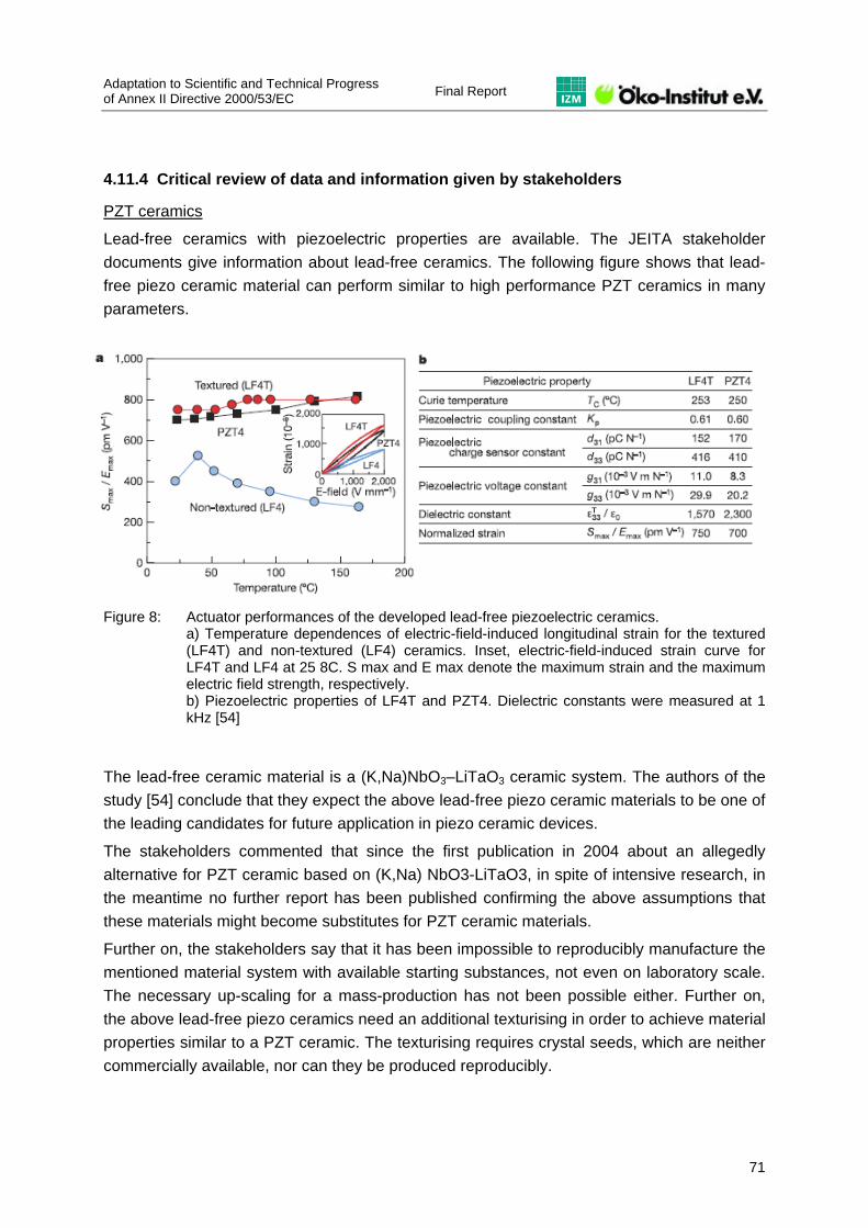
Adaptation to Scientific and Technical Progress of Annex II Directive 2000/53/EC Final Report
71
4.11.4 Critical review of data and information given by stakeholders
PZT ceramics
Lead-free ceramics with piezoelectric properties are available. The JEITA stakeholder documents give information about lead-free ceramics. The following figure shows that lead-free piezo ceramic material can perform similar to high performance PZT ceramics in many parameters.
Figure 8: Actuator performances of the developed lead-free piezoelectric ceramics. a) Temperature dependences of electric-field-induced longitudinal strain for the textured (LF4T) and non-textured (LF4) ceramics. Inset, electric-field-induced strain curve for LF4T and LF4 at 25 8C. S max and E max denote the maximum strain and the maximum electric field strength, respectively. b) Piezoelectric properties of LF4T and PZT4. Dielectric constants were measured at 1 kHz [54]
The lead-free ceramic material is a (K,Na)NbO3–LiTaO3 ceramic system. The authors of the study [54] conclude that they expect the above lead-free piezo ceramic materials to be one of the leading candidates for future application in piezo ceramic devices.
The stakeholders commented that since the first publication in 2004 about an allegedly alternative for PZT ceramic based on (K,Na) NbO3-LiTaO3, in spite of intensive research, in the meantime no further report has been published confirming the above assumptions that these materials might become substitutes for PZT ceramic materials.
Further on, the stakeholders say that it has been impossible to reproducibly manufacture the mentioned material system with available starting substances, not even on laboratory scale. The necessary up-scaling for a mass-production has not been possible either. Further on, the above lead-free piezo ceramics need an additional texturising in order to achieve material properties similar to a PZT ceramic. The texturising requires crystal seeds, which are neither commercially available, nor can they be produced reproducibly.

Final Report Adaptation to scientific and technical progress
of Annex II Directive 2000/53/EC
72
The material properties, according to the stakeholders, extremely depend on the temperature and various mechanical parameters. A stable performance within typical ranges of temperature and mechanical impacts is necessary. Material properties, necessary for automotive application, are thus not conceivable today.
The stakeholders also state that piezoelectric systems must be based on stable materials with marginal drift of properties and deterioration effects over the more than 10 years life time of a vehicle. The long-term performance of the mentioned material under continuous operation conditions is not known. Precarious for textured materials in this context is at least the stability of the magnetic domain dispersion as well as the extensive mechanical impact within inhomogeneous micro structures. This usually leads to fissures under the condition of a high dynamic electrical field, finally resulting in growing material cracks.
In its contribution automotive industry furthermore has stated that “Although intensive research materials with suitable material characteristics for automotive applications like long term temperature stability and sufficient strong piezo effects, necessary for advanced industrial serial products are only feasible with piezo-material still containing lead. Environmental advantages of these articles (e.g. emission reduction or fuel reduction by piezo injection systems) compensate marginal lead-content by far. […] Meanwhile efforts in research and development of the supplying industry in cooperation with public institutes will be continued to find lead-free alternatives, but these alternatives are not available today. [E.g.] There are intensive research efforts to develop lead-free alternatives, carried out as joint public funded projects10 as well as from the supplying industry of piezo ceramics, but today technical feasibility is not yet achieved.”
Based on these facts, the stakeholders conclude that the discussed lead-free peizo ceramics do not show material properties to be suitable for a substitution of PZT ceramics in vehicles. Additionally, these lead-free alternative piezo ceramic materials cannot be manufactured in industrial scale with reproducible properties.
The above information for itself is plausible. Opposing stakeholder views are not available. An extension of the exemption can be recommended. Based on the available information, it must be concluded that the use of PZT piezo ceramics cannot yet be substituted in vehicles.
Dielectric ceramics
The following table shows the properties of lead-containing versus lead-free dielectric ceramics. 10 Project funded by the German Ministry for Education and Research; 2006; Funded project no. 03X4002; Joint
partners: Robert Bosch GmbH, Siemens AG, Fraunhofer IKTS, Dresden, IKM, University of Karlsruhe, University of Hamburg-Harburg, University of the Land of Saar

Adaptation to Scientific and Technical Progress of Annex II Directive 2000/53/EC Final Report
73
Lead content typed ceramics (present)
Barium titanate typed ceramics
材料による発熱の比較Generation of heat comparisons of ceramic materials
Time (Minute)
Tem
pera
ture
(Cen
tigra
de)
AC 1kV/mm
Permittivity Dielectric
loss
DC Breakdown
voltage (%)
AC Breakdown
voltage (kV / nm)
Impulse Breakdown
voltage (kV / nm)
Lead content ceramics (present) 2’700 0.04 15.3 8.0 8.0
Barium titanate systems ceramics 3’000 0.80 11.8 6.7 6.0
Strontium titanate system ceramics 200
Remarks Largeness is good
Smallness is good
Largeness is good
Largeness is good
Largeness is good
Table 7: Properties of lead-containing versus lead-free dielectric ceramics [61]
The table shows that the parameters of lead-free dielectric ceramics considerably deviate from those of the lead-containing ones. The stakeholders consider the above properties of lead-containing ceramics as crucial for their applications in vehicles, and the lead-free alternatives are thus not appropriate.
PTC ceramics
The stakeholders say that due to the high temperature which is reached in automotive applications, only material endowed with lead-oxide shows a Curie temperature above 160°C, which is required in automotive applications. Opposing stakeholder views are not available.

Final Report Adaptation to scientific and technical progress
of Annex II Directive 2000/53/EC
74
Phase-out of lead in ceramics
JEITA set up a roadmap towards the substitution of lead in ceramics, as Figure 9 shows.
Figure 9: JEITA roadmap to the substitution of lead in ceramics [53]
The above roadmap shows for the PTC ceramics that there are several steps to go from the pure availability of a substitute material to its applicability in vehicles. This is plausible, as materials need to be tested and qualified for applications. In particular for the piezoelectric ceramics, JEITA seems not to consider any of the presented substitutes as a hot candidate for future lead-free PZT ceramics.
Automotive industry has stated that the presented roadmap cannot be applied as it stands for European automotive industry because it is not yet proven that the new materials would meet its requirements: “Up to now it is not possible to say if these materials can really be a substitute for PZT ceramics in automotive applications within the next 10 years.”
However, it needs to be mentioned here that substitution efforts have to be carried out by any automobile manufacturer putting vehicles on the EU market. Therefore, should substitution be feasible by a non-European manufacturer, there would be less justification for an exemption.
Lead-free materials for the ceramic materials discussed are not expected to be applicable in vehicles before around 2015. Opposing stakeholder views are not available. Based on the available information, the continuation of the exemption for lead in ceramics seems to be plausible.
Adaptation to Scientific and Technical Progress of Annex II Directive 2000/53/EC Final Report
75
4.11.4.1 Thickfilm technology and crosslinks to exemptions in the RoHS Directive
Lead is used in thickfilm technology. Lead-free alternatives to lead-containing thickfilm layers are available. They comprise borosilicate zinc glass and borosilicate bismuth glass; resistor alternatives include bismuth ruthenate, sodium ruthenate, strontium ruthenate and others. According to JEITA, the application in electrical components has been reported to be successful, but alternatives with the properties equivalent to lead-containing glasses/thick film layers are not available on the market [53]. Furthermore, the alternatives cannot yet suffice the requirements of the automotive industry.
Technical properties, such as e.g. the high heat resistance, make thickfilm applications indispensable. A change from thickfilm circuits to FR4 or other circuit technologies would only avoid the use of lead, if the solders to be applied as well as the component and printed wiring board finishes could be applied lead-free in vehicles. So far, this is not possible generally. A change-over from thickfilm to other technologies to avoid lead in thickfilm applications thus is not a general option, neither technically nor environmentally.
Developments in the review of exemption requests in the RoHS Directive
Industry so far has considered the use of lead in thickfilm applications to be covered by exemption 11 (Lead in “Electrical components which contain lead in a glass or ceramic matrix compound except glass in bulbs and glaze of spark plugs”). A technically identical exemption exists in the RoHS Directive: RoHS exemption no. 5 “Lead in glass of cathode ray tubes, electronic components and fluorescent tubes” or no. 7 “Lead in electronic ceramic parts (e.g. piezo electronic devices)”.
Current developments in the RoHS exemption request review must be taken into account, as the technical and scientific background for both the exemptions in the RoHS Directive and the ELV Directive is identical. A manufacturer of cermet-based trimmer potentiometers had requested a RoHS-exemption for the use of lead in thickfilms (http://circa.europa.eu/Public/irc/env/rohs_6/library?l=/exemption_requests/trimmer_potentiometer/proposal_2pdf/_IT_1.0_&a=d). The manufacturer stated that he does not see his application either under the existing RoHS exemption no. 5 “Lead in glass of cathode ray tubes, electronic components and fluorescent tubes” or under no. 7 “Lead in electronic ceramic parts (e.g. piezo electronic devices)”. The manufacturer said that the lead-containing material in the thickfilm layer is neither a glass nor a ceramic material. Industry so far had considered these exemptions to cover the use of lead in thickfilm pastes.
This development raised scientific doubts on whether entry no. 11 of Annex II ELV Directive (“Electrical components containing lead in a glass or ceramic matrix compound except glass in bulbs and glaze of spark plugs”) actually covers the thickfilm applications of lead-containing thickfilm layers in vehicles. At the stakeholder meeting in Brussels on 10 October 2007, after consultation with the Commission, the contractor had proposed to amend the

Final Report Adaptation to scientific and technical progress
of Annex II Directive 2000/53/EC
76
existing wording in order to increase the legal security for industry and to maintain the scientific consistency between the RoHS and the ELV Directive:
Electrical components containing lead in a thickfilm layer with resistive (…) functionalities or in a glass or ceramic matrix compound except glass in bulbs and glaze of spark plugs. The stakeholders were informed about the situation described above and asked to decide whether they still consider the wording of exemption 11 sufficient to cover the use of lead in thickfilm applications. It is the sole responsibility of the manufacturer or the user to decide whether an existing exemption covers the use of a banned material in a specific application. The stakeholders’ statements are therefore quoted:
“Cermets are basically considered as nonconductors/insulator and as sintered materials, which clearly indicates that they are considered as "Ceramic". Please see also the specific literature for these topic (e.g. Werner Schatt – Pulvermetallurgie, Sinter- und Verbundwerkstoffe, ISBN 3-7785-1319, s-527-531) or basic encyclopedias. There are however, "special" material combinations/ applications where the surface has been made conductive or special surface preparations to fix the cermets to a surface, which might also be conductive. To classify this "special applications" is far to complex for the daily business to classify a given component into a given exemption “In or out”. The most practical way for daily business is to group e.g. all cermets as "Ceramics". [59]
“As already proposed, the entry 11 should remain as it currently is: Electrical components which contain lead in a glass or ceramic matrix compound except glass in bulbs and glaze of spark plugs. By this wording, especially the ... compounds ... the automotive applications are well covered.” [59]
“The key to our interpretation is the term "compound" which should determine that the scope of consideration is not only the ceramic or glass matrix per se but also the constituting subparts attached to the referred matrix.” [60]
With this, the stakeholders (ACEA, CLEPA, JEITA) stated that they consider the existing exemption to cover the use of lead in thickfilm applications. The above explanation is solely and exclusively the responsibility of the stakeholders. The contractor hence does not comment or further question this explanation.
An amendment of the existing exemption with regard to the use of lead in thickfilm applications therefore is obsolete in this review process.

Adaptation to Scientific and Technical Progress of Annex II Directive 2000/53/EC Final Report
77
4.11.5 Final recommendation
The stakeholders provided plausible and comprehensive information on the necessity of lead in ceramics and in thickfilm technology circuits, and on the functional necessity of these ceramics and thickfilm applications. Lead-free ceramics and in parts also thickfilm materials are available, but in parts not in industrial scale, or with properties that are relevantly inferior to those of the lead-containing ones for use in vehicles.
Based on the available information it can be concluded that the use of lead in these applications at the current state of the art is not avoidable.
The stakeholders decided that the current exemption wording covers all their relevant uses of lead in ceramics. It is hence recommended to continue the exemption with the current wording.
4.11.6 References
[52] Stakeholder document “JEITA Comment_ELV_CeramicMaterials.doc”
[53] Stakeholder document “JEITA Comment for questions on exemption 11.ppt”
[54] Stakeholder document “JEITA Comment_ELV_CeramicMaterials_Annex.pdf”
[55] Stakeholder document “JEITA Comment_ELV_CeramicMaterials_Annex_2.pdf”
[56] Stakeholder document “JEITA Comment_ELV_CeramicMaterials_Annex_3.pdf”
[57] Stakeholder document “CCFA on Entry 11.doc”
[58] Stakeholder document “CCFA on Entry 11_justification-1.doc”
[59] E-mail communication with Mr. Harald F. Schenk, ACEA, 2 November 2007
[60] E-mail communication with Mr. Yoji Arikura, JEITA, 12 November 2007
[61] E-mail communication with Mr. Bernhard Reischl, Siemens VDO, 4 December 2007
[62] ACEA, document downloadable from ACEA website http://acea.thisconnect.com/images/uploads/VEHICLE_REGISTRATIONS_2006.pdf; last access 3 December 2007
[63] Lohse, L.; Sander, K.; Wirts, M.: Heavy Metals in Vehicles II (Final Report), Ökopol – Institut für Ökologie und Politik GmbH, Hamburg July 2001 Report compiled for the Directorate General Environment, Nuclear Safety and Civil Protection of the Com-mission of the European Communities Contract No B4-3040/2000/300649/MAR/E.3

Final Report Adaptation to scientific and technical progress
of Annex II Directive 2000/53/EC
78
4.12 New request for exemption “Lead in frit glass used in Vacuum Fluorescent Displays”
4.12.1 Description of requested exemption
The company Futaba has brought forward a request for exemption on “lead in frit glass used within Vacuum Fluorescent Displays (VFD)” to the European Commission and was subsequently part of the last stakeholder consultation. In that context, stakeholders were invited to comment on whether they shared the need for such an exemption or whether they would rather oppose it.
The Bavarian Ministry for Environment is the only stakeholder having brought forward a comment in this respect. Therein, it stated that the application mentioned in the exemption request could be covered by the already existing entry no. 11 (“electrical components which contain lead in a glass or ceramic matrix compound except glass in bulbs and glaze of spark plugs”). Only if this was not the case it would support such an exemption to be newly added to Annex II ELV Directive.
In its request documentation, the applicant states that VFDs are used as displays in automotive applications. Lead is used in glass for
sealing package (vacuum vessel);
grid electrode bonding material;
electrode terminal;
electrode contact of wires and anode electrode;
film insulator.
During the evaluation, the new request has to be assessed on the basis of Article 4(2)(b)(ii): is the use of heavy metals in this application indeed unavoidable and an exemption thus justified?
4.12.2 Justification for new exemption
The applicant states that „no substitute glass material, which gives a low softening point enough to be sintered around 450°C and maintain vacuum within VFD, is available for sealing“.
According to the applicant, substitute needs to satisfy following requirements:
Adjusting softening temperature between 350°-600°C;
Having chemical stability inactive to organic material used for paste;
Having expansion coefficient equal to that of the glass which constitutes the package;
Having chemical resistance and weather ability as seal glass which consists of vacuum components.

Adaptation to Scientific and Technical Progress of Annex II Directive 2000/53/EC Final Report
79
4.12.3 Critical Review
Questions were sent out to the applicant prior to the technical workshop in order to clarify many open issues addressed in its supporting documentation. The applicant provided extensive and comprehensive answers during the workshop.
However, discussions taking place among industry prior to the workshop lead to the conclusion that the applicant did indeed consider his application to fall under the scope of existing exemption no. 11. Only, had he filed a request for exemption because he had been made insecure by business partners denying this.
During the technical workshop on 10 October, the applicant stated that after having had a neutral expertise carried out by Ökopol which confirmed that his application was covered by entry no. 11 he would like to withdraw his exemption request. The applicant made the Ökopol expertise available to the contractor.
Furthermore, as a comment to the interim report, the applicant made clear that it had not been his intention to request an additional exemption for his products but rather to reach clarification on the applicability of existing exemption no. 11. This, he claimed, has now been described consensually by all relevant parties.
4.12.4 Final recommendation
Since – as a conclusion of the workshop – the exemption request has become obsolete, no recommendation is given.
4.13 Exemption no. 12 “Pyrotechnic initiators”
4.13.1 Description of existing exemption and request for extension
Pyrotechnic initiators which contain lead11 are currently exempted from the requirements of the ELV Directive (entry no. 12). In this evaluation it has to be assessed whether this exemption is still justified and if the use of heavy metals – here lead – in this application is indeed unavoidable.
Lohse et al. concluded in 2001 as follows:
“The phase out of lead in pyrotechnic initiators is technically possible. 25% of the European cars contain a high energy system which is already lead-free. The change to lead-free systems for the low energy systems (75%) is likely to need more time due to long development, validation and qualification procedures in these safety relevant applications.
11 As lead styphnate (lead-2,4,6-trinitroresorcinate; CAS 15245-44-0)

Final Report Adaptation to scientific and technical progress
of Annex II Directive 2000/53/EC
80
The amounts are low with a maximum of 310 mg lead per car. A temporary exemption for lead in pyrotechnic initiators appears reasonable and does not give rise to a considerable drawback for the aim of reducing lead in the shredder light fraction, because the amounts of lead are relatively low.”
On request by Öko-Institut OEM argue as follows:
“As all others already stated, the Ökopol findings are still valid and justified. Almost all vehicle manufactures do still have vehicles in current series production which have been Type Approved prior July 2006. The production volume of these mentioned vehicle models however, is by far lower than the production volume of vehicles using lead-free systems. …”
Therefore, CLEPA12 calls for continuance of the existing exemption: “The current wording of the exemption should definitely remain unchanged. This is absolutely necessary to avoid the safety concerns associated with changing running series, as already mentioned. The same argument is valid when it comes to providing replacement parts. These should be provided “as originally produced.” Thus it would be possible to produce and repair or service "old" vehicle generations using the technology which has been developed, tested and validated for this generation.”
4.13.2 Justification for continued exemption
The main arguments for a continued exemption can be summarised as follows:
CLEPA member companies have introduced lead-free alternatives for all product developments for vehicles type approved after 1 July 2006, in line with the Annex II exemption.
Research and development have been done in close cooperation with the manufactures/suppliers of the Pyrotechnic Systems, to ensure the legal compliance as of July 2006. All these new developments as of that date are lead-free.
The number of lead-containing pyrotechnical applications has decreased over the past years continuously. According to CLEPA the production volume of initiators with lead for vehicles type approved before 1 July 2006 is about 10% of an annual total volume of 80 million initiators and constantly decreasing.
Running series of vehicles type approved prior to July 2006, however, cannot be converted due to technical and safety reasons. Alternatives for Pyrotechnic Systems for vehicles type approved prior to July 2006 have not been investigated as it is technically not possible to replace them.
12 European Association of Automotive Suppliers

Adaptation to Scientific and Technical Progress of Annex II Directive 2000/53/EC Final Report
81
4.13.3 Critical Review
Pyrotechnic initiators are elements of the so called ignition train which is used for dynamic occupant protection systems (belt pretensioners and airbags).
CLEPA and OEM provided detailed information about lead in pyrotechnic initiators, encompassing detailed product description and fields of application, figures about amounts and environmental relevance, the state of alternatives and the challenges associated when changing to lead-free alternatives. Summarising these information it is evident, that there are two main technologies:
Low-energy electronic control units using lead components as pyrotechnic initiator, and
High-energy electronic control units where lead-free initiators are available.
Due to the fact that pyrotechnic initiators are part of complex systems consisting of sensors and electronic units, the pyrotechnic initiators, inflators, airbag modules or seat belt pretensioners respectively, it is comprehensible that a change of one or more parts of this system requires re-qualification of the complete vehicle occupant protection system. Furthermore it is evident that the different technologies cannot be interchanged.
Taking into account the specific amounts with a maximum of 310 mg lead per car the additional contribution to the total lead content of a car is quite low. Therefore the potential environmental relevance of the usage of lead-containing pyrotechnic initiators is almost negligible.
4.13.4 Final recommendation
Taking into account the above discussed question and answers the requested continued exemption should be granted, keeping the existing wording.
4.13.5 References
[64] Lohse, J. et al. (2001); Heavy Metals in Vehicles II (Final Report); Ökopol – Institut für Ökologie und Politik GmbH, Hamburg, Germany; Report compiled for the Directorate General Environment, Nuclear Safety and Civil Protection of the Commission of the European Communities Contract No B4-3040/2000/300649/MAR/E.3

Final Report Adaptation to scientific and technical progress
of Annex II Directive 2000/53/EC
82
4.14 Exemption no. 13(b) “Hexavalent chromium in corrosion preventive coatings related to bolt and nut assemblies for chassis applications”
4.14.1 Description of existing exemption
The use of hexavalent chromium in corrosion preventive coatings is currently represented with two entries in Annex II:
Entry 13(a): Corrosion preventive coatings (expiry date: 1 July 2007)
Entry 13(b): Corrosion preventive coatings related to bolt and nut assemblies for chassis applications (expiry date: 1 July 2008)
The scope of this evaluation relates only to the second entry since the first one has already expired before this contract started.
Historically the use of CrVI for the purpose of corrosion prevention was dealt with by the two Ökopol studies on the use of heavy metals in vehicles in 2000 and 2001 (cf. http://ec.europa.eu/environment/waste/studies/elv/heavy_metals.htm) which led to a first amendment of Annex II in 2002. A second amendment took place in 2005 on the basis of the results of a stakeholder consultation. The first adaptation set an expiry date for 1 July 2007 for all applications of CrVI in corrosion preventive coatings. The second adaptation then led to the above mentioned split into two entries.
The third adaptation of Annex II is to be done on the basis of the results of the last stakeholder consultation. Unfortunately, no comments were received with regard to entry 13(b), except a general signal by automotive industry that it agreed to keep the expiry date as it is.
Entry no. 13 has to be evaluated with regard to exemption requests under the RoHS Directive: four exemption requests have been brought forward with regard to the use of CrVI in electrical and electronic equipment:
1. no. 5 second consultation (“Hexavalent chromium passivation coatings”)
2. no. 7 third consultation (“CrVI in chromate conversion coatings and surface treatment”
3. no. 2 sixth consultation (“Pb as soldering alloy in high performance communication electronic board and CrVI”)
4. no. 18 sixth consultation (“CrVI used as a passivate”)
Only the first request mentioned above received a positive recommendation which led to entry no. 28 of the RoHS Annex (“Hexavalent chromium in corrosion preventive coatings of unpainted metal sheetings and fasteners used for corrosion protection and Electromagnetic Interference Shielding in equipment falling under category three of Directive 2002/96/EC (IT and telecommunications equipment). Exemption granted until 1 July 2007.”).

Adaptation to Scientific and Technical Progress of Annex II Directive 2000/53/EC Final Report
83
The Ökopol report of 2001 on heavy metals in vehicles, describes that “protective coatings based on hexavalent chromium are very effective because of their ‘self-healing’ properties after small injuries on the surface layer”. However, the report says that “it is possible to produce cars without Chromium-VI in most applications already, with some remaining problems in the supply chain”. Restrictions were only mentioned with regard to the technical importance and the variety of application fields. It is assumed that this led to the currently existing entry no. 13(a) and (b).
The automotive industry has commented that it opposes “to the statement that in 2001 the production of Cr(VI)-free vehicles would have been possible […]. In 2001, neither adequate sufficient substitutes were available, nor were sufficient production volumes given. In addition, the quality of the first samples and test specimens in round robin tests was very unsteady, and it took some years of intensive work to bring quality to an acceptable and responsible level. In 2001 there was a lack of field experiences with pilot substitute applications.”
Furthermore, automotive industry has brought forward arguments concerning a need for spare parts’ exemption beyond the expiry date for entry no. 13. This is being dealt with in a separate process (cf. http://circa.europa.eu/Public/irc/env/elv/library?l=/stakeholder_consultation_1&vm=detailed&sb=Title).
4.14.2 Justification for continued exemption
Since from the side of the industry – that had claimed that an extension of the initial general expiry date of 1 July 2007 was necessary – no contribution was brought forward on a further extension of exemption no. 13(b), there seems to be no need for a new expiry date. No documents justifying a further exemption have been received by the contractor.
4.14.3 Critical Review
Looking at the fact that substitution was already possible in most applications some years ago and that Annex II has been subsequently changed towards a phase-out of CrVI passivation coatings by 1 July 2007 (except for some specific applications), it appears logical that full phase-out can be achieved by 1 July 2008.
Furthermore, the exemption on CrVI under the RoHS Directive was harmonised with the 1 July 2007 expiry date of the ELV Directive. This harmonisation should not be counteracted by an extension of the current expiry date of entry 13(b).
With the upcoming Commission Decision on the issues of “repaired as produced” – also covering entry no. 13 – industry’s remaining concerns should be addressed in an appropriate way.

Final Report Adaptation to scientific and technical progress
of Annex II Directive 2000/53/EC
84
4.14.4 Final recommendation
Concluding from the above, it is recommended not to extend the expiry date of entry no. 13(b).
4.15 Exemption no. 14 “Absorption refrigerators in motor caravans”
4.15.1 Description of existing exemption
Chromate is currently used as a corrosion inhibitor in absorption refrigerators. These kinds of refrigerators are inter alia used in caravans and motor homes due to the fact that they can work independently from electricity with a heat-driven technology using gas (propane / butane) or kerosene as energy source. Furthermore, they have the advantage that they have no moving parts and are thus completely silent, making them further attractive for the use in caravans or motor homes.
Dometic – formerly Electrolux – states to be one of the main producers of absorption refrigerators in Europe. Its absorption cooling units are constructed in carbon steel because of its strength and good welding properties. The refrigerant is an ammonia-water solution. The absorption cooling system is a completely closed system, which is pressurised with hydrogen gas. In order to prevent corrosion of the carbon steel cooling system sodium chromate is added to the refrigerant.
Dometic says: “Using chromate, a passive layer of chromium/iron oxide (Cr2O3 /γ-Fe2O3) is formed at the steel surface and no precipitates that block the circulation are formed. Chromate is slowly consumed and experience has shown that the service life exceeds 10 years of continuous operation.”
The current exemption was granted due to the fact that industry claimed not to have found an alternative to chromate so far. The use of CrVI for corrosion protection is not only exempted from substance restrictions under the ELV Directive but is also included in the Annex to the RoHS Directive and thus exempted from its substance requirements too (item no. 9).
According to Dometic, the annual production of absorption fridges in Europe amounts to 600’000-700’000 pieces in 2006. Taking into account that out of these 120’000 were sold to caravans and 90’000 to Motor Caravans with an average amount of 4 g CrVI per fridge, the total annual amount sums up to 0.84 t of CrVI in ELV relevant applications.
Apart from Dometic – who requests an extension of the current exemption – a stakeholder contribution was received by its main competitor Thetford. Thetford says to produce 60’000 refrigerators for campers and caravans annually and also supports a continuation of the exemption.

Adaptation to Scientific and Technical Progress of Annex II Directive 2000/53/EC Final Report
85
4.15.2 Justification for continued exemption
Dometic has provided supporting evidence for an extension of the exemption and justifies its request as follows:
Extensive research has been carried out at Electrolux between 1920 and 1999 as well as at Dometic between 2000 and now (Dometic claims to have about 300 test related cooling units that have been started since 2000): “Electrolux/Dometic has been conducting research into finding possible alternatives for the corrosion protection of absorption refrigerators. Not only has a significant in-house commitment been made but also Electrolux/Dometic has worked with a number of external research institutes and universities on this issue. Several long-term projects have been run with theoretical and practical studies on the corrosion process. Work has also been carried out with companies who are expert in corrosion protection where commercial inhibitors have been tested. The research has looked at alternative refrigerants, inhibitors, structural materials, surface treatment and combinations thereof.” Extensive and comprehensive documentation on these research activities has been provided as evidence.
However, according to Dometic, no suitable alternative could be found. This is justified via the following parameters:
‒ Reduced life length of an alternative corrosion inhibitor “The expected life length of an absorption refrigerator with hexavalent chromium as corrosion inhibitor is 15-20 years at continuous operation. For an absorption refrigerator with no inhibitor at all, the service life length is less then 1 year13. […] The statistical numbers of units using an alternative inhibitor are still too few to be able to foresee a firm service length. However, our tests of an alternative inhibitor show an average indicative life length of 3-5 years. A shorter life length would result in a higher exchange frequency of products and consequently a more negative impact on the environment.”
‒ Reduced product safety “Since the estimated life length of an absorption refrigerator with an alternative corrosion inhibitor is considerably less then one filled with hexavalent chromium, the risk that a leakage [releases of ammonia and hydrogen into the surroundings] would occur during active use of the absorption refrigerator is significantly higher.”
‒ Reduced product performance “When using an alternative corrosion inhibitor instead of hexavalent chromium, the cooling performance will decrease with approximately 3-4°C in the cooling compartment.” The lower temperature is said to lead to lower customer satisfaction.
13 „An absorption cooling unit filled with ammonia and water without any inhibitor will immediately be attacked by
corrosion. Corrosion products will block the circulation and within less than one year the function ceases.”

Final Report Adaptation to scientific and technical progress
of Annex II Directive 2000/53/EC
86
‒ Lower energy efficiency “In order to compensate for a loss in temperature performance of 3-4°C, increased energy consumption would be necessary.” The increase in energy consumption is said to be of approximately 10-15%.
Dometic states that at least 10 years are needed in order to phase-out CrVI from their refrigerators and that an expiry date should be set earliest at that point of time. Furthermore it is stated that an acceptable maximum amount of CrVI would be 1.0 weight-% of CrVI based on the water part of the cooling solution.
Thetford delivers arguments that go into the same direction, but did not provide any evidence or supporting documentation. Statements given are summarised as follows:
Thetford is about to come to an agreement with a German researcher which has already done research on CrVI alternatives in the past. Also, its cooling unit supplier in the U.S. has done research in conjunction with a local university. However, Thetford says not to be at liberty to share results with the contractor.
Thetford feels it is currently impossible to deliver a roadmap or similar evidence showing the foreseen development of substitution efforts. It only states: “Limiting the environmental impact of our products is an important element of our philosophy, so obviously the research into possible alternatives for CrVI is important to us. We are aware of the regular revision of Annex II of the ELV, and we are also aware that the exemption for CrVI could end some time in the future. We intend to replace CrVI as a corrosion inhibitor as soon as an alternative can be found that has a significantly lower environmental impact than the current solution.”
As concerns the availability of substitutes, Thetford claims that “To-date, no other substance has been able to produce the same effect while keeping sufficient inhibitor in solution to insure long life of the refrigerator.”
4.15.3 Critical Review
Evaluating the above-mentioned arguments the following can be concluded:
Comprehensive evidence was given on Dometic’s past and current commitment to investigate alternatives to CrVI. Many alternatives have been looked at such as oxidising and non-oxidising inhibitors as well as changes in material and design of the product itself. In its contribution, Thetford supports this statement.
From the current documentation it can thus be concluded that currently substitution is not possible. However, information is missing on whether the proposed expiry date of today + 10 years is reasonable and on whether the proposed maximum concentration value is a useful limitation of CrVI content. These aspects could not be evaluated due to time constraints.

Adaptation to Scientific and Technical Progress of Annex II Directive 2000/53/EC Final Report
87
Other absorption refrigerator manufacturers such as Waeco and Sibir have been contacted but without any significant gain in information. However, the contractor was later on informed that both companies are owned by Dometic. It was thus decided not to carry out more intensive research with these manufacturers, since it is assumed that the statements received by Dometic reflect the status quo of research in these two companies too.
Also, information is needed on alternative cooling systems in motor caravans and motor homes. Since no information was available to the contractor at time of drafting this report, this aspect would need to be investigated further.
In addition, it has to be mentioned that an exemption with a similar wording is included in the RoHS Annex and that this exemption under RoHS is subject to review in the course of 2008. In view of consistency, evaluation of both areas of application should be done in parallel.
In order to address all these issues and with a view of a more efficient information exchange, a meeting with relevant stakeholders would be necessary. Unfortunately, this goes beyond the contractor’s time and budget capabilities within this assignment.
Exemption no. 14 was not part of the stakeholder consultation. This resulted in the non-availability of information at the beginning of the evaluation procedure. Due to the provision of information late in the process, it was not possible to carry out a full in-depth evaluation until now. Questions that still need to be clarified are:
‒ What would be an acceptable reduction of a refrigerator’s lifetime if using CrVI-free corrosion inhibitors from a technical and scientific point of view? Currently, the estimation of a reduced lifetime to 3-5 years is only very vague and based on too little test units.
‒ What possible increase in energy consumption would be acceptable from an environmental point of view if a certain loss in temperature performance would be accepted when using CrVI-free corrosion inhibitors? Would the standard specifications for caravan refrigerators still be met?
‒ What is the roadmap used by manufacturers concerning CrVI substitution?
4.15.4 Final recommendation
The argumentation of Dometic and Thetford in favour of an extension of the current exemption seems logical and sound. However, not all aspects could be evaluated in full depth. Further exchange with manufacturers and other stakeholders is needed in order to give a sound and technically founded evaluation. In addition, it is recommended to align with the results of the ongoing revision of the corresponding RoHS exemption (entry no. 9), taking the different fields of application into account.

Final Report Adaptation to scientific and technical progress
of Annex II Directive 2000/53/EC
88
It is thus recommended to continue this exemption until a full assessment has been carried out and until the evaluation under the revision of the RoHS Directive’s Annex has been completed. The proposed review date is thus 31 December 2008. By this date, the RoHS exemption evaluation will have been finalised and the entry of ELV Annex II can then be revised accordingly if necessary.
4.16 Exemption no. 15 “Discharge lamps which contain mercury and instrument panel displays”
4.16.1 Description of existing exemption and request for extension
Discharge lamps and instrument panel displays which contain mercury are currently exempted from the requirements of the ELV-Directive (entry no. 15). In this evaluation it has to be assessed whether this exemption is still justified and if the use of heavy metals – here mercury – in this application is indeed unavoidable.
Sander et al. concluded in 2000 as follows:
Gas discharge devices for headlamps:
‒ During use, mercury containing gas discharge bulbs have clear advantages over halogen lamps.
‒ During ELV disposal, mercury containing bulbs are rather time-consuming to dismantle and very expensive to dispose of. High dismantling quota can therefore only be expected when the dismantling and/or disposal will be subsidised.
Instrument panel displays:
‒ While there are no mass production approved alternatives for background illumination yet, mercury containing bulbs for lighting of the passenger room or loading compartment are replaceable.14
Several industry associations (ACEA, CCFA, VDA, JAMA, KAMA) argued in an identical contribution to the stakeholder consultation that they cannot support the removal of the current exemption. The associations propose to leave the existing exemption unchanged until July 2012 and suggest setting the scope as follows:
Discharge lamps and instrument panel displays;
Vehicles type approved before 1 July 2012 and spare parts for these vehicles.
14 However, this statement relies partly on a misunderstanding as bulbs for lighting of the passenger room or
loading compartment are not to be assigned to the application “instrument panel displays”.

Adaptation to Scientific and Technical Progress of Annex II Directive 2000/53/EC Final Report
89
Furthermore, it is suggested to review this exemption in 2010 when sufficient reliability data and all necessary components with appropriate quality level should be available, to finally assess if a phase out is really possible.
4.16.2 Justification for continued exemption
4.16.2.1 HID Headlight Lamps
In the stakeholder consultation and in the follow-up process to the stakeholder workshop held in Brussels on 10 October 2007 it was conceded that there are viable substitutes for mercury containing gas discharge devices for headlamps. According to the statement of the European Lamp Companies Federation (ELC) mercury free HID Headlight lamps for automotive purposes are available on the market and ELC member companies actively assist the automotive manufacturers to use these products.
Generally, two technologies exist for head lighting: conventional incandescent (halogen) and gas discharge lamps. The gas discharge lamps are filled with a mixture of sodium, scandium and mercury as illuminating materials. Electronic lamp drivers are necessary to operate these kinds of lamps. Compared to conventional halogen lamps the mercury containing light system has clear advantages especially in terms of light intensity, longer lifetime, whiter light and better energy efficiency.
ELC states that substitution of mercury would be possible using Zinc compounds that can evaporate almost as quickly as Mercury, and also emit light in visible wavelength spectrum. This would allow balancing the lamp efficacy versus operation conditions on an adequate level similar to a mercury containing lamp. Also the Hg-free lamp needs to be operated with an electronics driver, but different from the current one, as lamp voltage is lower.
Despite the availability of mercury free HID lamps contributions from automotive industry stakeholders included the following arguments for continued exemption:
Not only the bulb but the whole system needs to be changed and to be designed more robustly.
Substitutes will have different ramp-up behaviour15.
International Standards do not allow for the interchange of lamps in the head lamp for safety reasons, i.e. substitution can only take place in new vehicles which are re-designed accordingly.
The related OEM together with CLEPA submitted a roadmap illustrating the implementation of mercury-free discharge lamps, implying the following steps:
15 Time between starting the headlamp and full illuminating power.

Final Report Adaptation to scientific and technical progress
of Annex II Directive 2000/53/EC
90
Supplier sourcing process;
Concept and detailing phase;
Qualification product and process;
Safety validation, pedestrian impact etc.;
Ramp up.
The total period covering these steps is about 4 years.
4.16.2.2 Instrument Panel Displays
In this case of application mercury containing fluorescent tubes are used as lighting source for instrument panels. There are mercury free alternatives, not realised by substituting the material but by utilising another light-source technology i.e. LED. LED technology is available but introduction to the automotive sector is recent. According to the position of OEM and CLEPA the entire instrument panel display had to be redesigned because
“LED is a completely different light source compared to commonly used compact fluorescent lamp;
LEDs differ in power supply (DC not AC), illumination pattern (require other prism to direct/spread light), geometry, heat management when compared to fluorescent lamps;
There are mechanical constraints and fluorescent lamps can not simply be replaced by LEDs as packaging and Printed Circuit Board (PCB) layout are completely different.”
Moreover the compliance with legislation in terms of type approval has to be demonstrated, involving
Electro-Magnetic Compatibility (UN/ECE Regulation10);
Interior protection (UN/ECE Regulation 21);
Control tell tales (UN/ECE Regulation 121).
Like in the case of headlight lamps the related OEM together with CLEPA submitted a roadmap illustrating the implementation of mercury-free Instrument Panel Displays. Here again the total period covering the individual implementation steps is about 4 years.
4.16.3 Critical Review
Analysing the argumentation more in detail, the following points are essential:
Although there is currently a common exemption for both, discharge lamps and instrument panel displays, they are in fact two different applications with different possible substitutes.
Based on data provided by ELC the total annual quantity of mercury in discharge lamps for headlights can be estimated as follows:
‒ Per lamp the average mercury content is about 0.5 mg.

Adaptation to Scientific and Technical Progress of Annex II Directive 2000/53/EC Final Report
91
‒ Total lamp market is about 15 M/yr, the total amount of mercury accounts therefore for about 7.5 kg/yr.
The automotive industry provides slightly divergent data as follows:
‒ About 8 Mio gas discharge headlamp systems are currently in the market, corresponding to 4 kg mercury.
‒ The annual volume of discharge headlamps in Europe is about 2.5 Mio units, corresponding to 1.25 kg mercury.
Furthermore, the automotive manufacturers estimate that in OEM equipment around 5 kg mercury are used within the EU for displays illumination purposes.
In their common statement OEM and CLEPA provided data illustrating the advantages of HID-System compared to conventional halogen system in terms of energy efficiency. According to this, mercury free system would lead to a slightly higher energy consumption compared to HID-Systems with mercury.
Table 8: Energy consumption of different lighting technologies for instrument panel displays
Power (Watt)
Halogen System (12V)
Halogen System (13,5V)
HID-System with Hg
HID-System
without Hg LED today* LED 2015**
forecast
Lamp 55 65-70 35 35 50 35
Electronic Control Unit 7 9 9 7
Additional Equipment like cooler
2
Total 55 65-70 42 44 61 42
Principally LED-Technology (which doesn’t contain mercury) is expected to have less energy consumption through a better performance and a better light intensity ramp up. However, LED headlamps without mercury and with lower energy consumption are expected to be put on the market as HID’s around 2015. However, more in depth information on the basis of a life cycle assessment was not provided by stakeholders.
Although the roadmap for both applications (headlamps and instrument panel displays) appears basically comprehensible, it will not be possible within the time frame of this study to retrace all of the single steps and qualification procedure. At first sight the time frame for implementation seems to be rather long-term. However, it is not possible to judge about this case here explicitly.

Final Report Adaptation to scientific and technical progress
of Annex II Directive 2000/53/EC
92
4.16.4 Final recommendation
Taking into account the above discussed question and answers the requested continued exemption should be granted. However, the existing exemption was not defined specifically and covers two different applications with different possible substitutes. Against this background we recommend to split the existing exemption into two new exemptions, reflecting the different nature and phasing out situation of the two applications. Therefore, the wording is suggested as follows:
Mercury in discharge lamps for headlight application in vehicles type approved before 1 July 2012 and spare parts for these vehicles. Entry to be reviewed in July 2010.
Mercury in fluorescent tubes used in instrument panel displays in vehicles type approved before 1 July 2012 and spare parts for these vehicles. Entry to be reviewed in July 2010.
The suggested review date is considered to be appropriate in order to reflect the currently dynamic phasing out of mercury in both applications. This review would enable (if necessary at all) a further prolongation of the expiry date in sufficient time, thus giving planning reliability along the supply chain.
In view of consistency in environmental legislation, the contractor would like to remark that the RoHS Directive’s Annex also includes an exemption for the use of mercury in lamps (entries no. 1-4). Currently, the wording of both exemptions is not consistent. For future reviews of exemptions under both Directives, a harmonisation of the wording reflecting similar or identical technical specifications should be taken care of.
4.16.5 References
[65] Sander, J. et al. (2000); Heavy Metals in Vehicles (Final Report); Ökopol – Institut für Ökologie und Politik GmbH, Hamburg, Germany; Report compiled for the Directorate General Environment, Nuclear Safety and Civil Protection of the Commission of the European Communities Contract No B4-3040/2000/300649/MAR/E.3
4.17 Exemption no. 17 “Batteries for electrical vehicles”
4.17.1 Description of existing exemption
An exemption for the use of NiCd batteries has already been part of the first adaptation of Annex II in 2002. This was based on the following previous assessment by Ökopol in 200116:
16 cf. http://ec.europa.eu/environment/waste/studies/elv/heavy_metals.htm

Adaptation to Scientific and Technical Progress of Annex II Directive 2000/53/EC Final Report
93
Electrical vehicles (EV) put on the market in the EU in a majority use NiCd batteries. However, EV powered by lead-acide and NiMH technology are also available on the market.
Especially, NiMH batteries are well-established for hybrid vehicles. Their availability for series production of pure electrical vehicles is seen controversially by different stakeholders, which appears to be mainly the result of economic considerations rather than a technical problem.
Li-ion batteries are said to have the greatest potential for the future.
The exemption was at first limited until 31 December 2005 (except for the use as replacement parts). However, during the stakeholder consultation in 2004 the following points were brought forward by industry:
No substitutes exist; only a few different technologies are under development (not yet certified for automotive traction power by vehicle manufacturers).
No manufacturing infrastructure exists for more than 10’000 units which is needed for a commercial launch.
There should be no phase-out with a view to legal consistency with the Battery Directive (Commission's extended impact assessment for new Battery Directive specifically forbids any ban or marketing restrictions on NiCd batteries fulfilling the requirements of the Directive).
Extension of exemption required until 2010 (it takes 5 years to develop an electrical vehicle once the battery technology has been validated).
NiMH and Li-ion electrical car batteries are technically available and substitution is feasible (SAFT markets NiMH and Li-ion batteries for EV). Exemption should not be continued.
Some substitutes have reached a high-level of maturity and require the final support to achieve production readiness).
Subsequently, the second adaptation of Annex II in 2005 included an extension of the exemption until 31 December 2008.
On this basis, the Commission needs to assess by 31 December 2007 whether substitutes are available and whether a further extension of the expiry date is necessary. Therefore, stakeholders were requested to comment during the 2006 stakeholder consultation.
Comments submitted are summarised as follows:
Exemption should be extended until the end of December 2010 inter alia for the following reasons:
‒ SUBAT study established that industry needed until end 2010 to develop industrial projects for environmental friendly vehicles

Final Report Adaptation to scientific and technical progress
of Annex II Directive 2000/53/EC
94
‒ Ni-Cd batteries for electrical vehicles are collected and recycled ensuring that there is no impact on the environment at the end of life.
‒ Necessity to maintain the industrial infrastructure and expertise for current and future electrical vehicle programs.
‒ Continuation of production facilities ensures that replacement of Ni-Cd batteries can be provided
In the course of the current evaluation, stakeholders in favour and against a prolongation of the exemption were asked to answer more detailed questions (cf. Annex) and to submit further evidence supporting their views.
4.17.2 Justification for (dis)continued exemption
Several statements were received as a reaction to the questions sent out to stakeholders:
Statement by SAFT (NiCd battery manufacturer) requesting an extension until 2010 (with a review by the Commission in 2009)
Statement by the German Federal Environmental Protection Agency (UBA) supporting an expiry by 31 December 2008 as currently foreseen
Statement by automotive industry agreeing on an expiry of the exemption by 31 December 2008 (except for the use as replacement part).
Arguments included in these contributions are summarised as follows:
SAFT further argues that substitutes (e.g. Ni-MH and Li-ion) are not available in sufficient quantity needed for a commercial launch (10.000 units/year), that pure electric vehicles (in opposition to hybrid vehicles) working on the basis of such substitutes have “failed to materialise in substantial customer orders” and that an extension until 2010 is required since it takes 5 years to develop an electrical vehicle once the battery technology has been validated.
UBA on the other hand states that there are indeed vehicles put on the market containing Ni-MH or Li-ion batteries and that – on the German market at least – there are no electric or hybrid vehicles containing NiCd batteries. This statement has been supported with statistical data on car registrations. Furthermore, it is argued that no inconsistency is seen with the regulations of the Battery Directive, that industry has been aware of the limitation of the exemption in time since 2002 (and thus had 6 years to adapt) and finally that since substitutes are available, there is no justification for an extension of this exemption.
The automotive industry states that electric cars put on the market now do not contain NiCd batteries anymore. An exemption beyond 2008 is thus not necessary except for the use of NiCd batteries as replacement parts.

Adaptation to Scientific and Technical Progress of Annex II Directive 2000/53/EC Final Report
95
4.17.3 Critical Review
Concluding on the above mentioned stakeholder comments, it can be stated that from a technological point of view there is no justification for an extension of the current exemption. Arguments brought forward by SAFT were not supported by evidence. Furthermore, the general availability and technical feasibility of substitutes is not questioned by SAFT. Since automotive industry itself does also not see the need for a further extension, no grounds are given for a prolongation of the exemption. However, extending the exemption for replacement parts seems to be appropriate with a view to consistency with the principle of “repaired as produced”.
4.17.4 Final recommendation
With regard to the above conclusion it is recommended to keep the current expiry date of 31 December 2008. After that date the Annex should only include an entry stating “After 31 December 2008, cadmium in batteries of electrical vehicles used as replacement parts”.
5 Further proceeding
This final report will be published on the project website at http://circa.europa.eu/Public/irc/env/elv/library?l=/stakeholder_consultation/evaluation_procedure&vm=detailed&sb=Title.
Since many exemptions could not be evaluated in full depth and did thus not lead to sound recommendations, a further evaluation process should be carried out after this project has ended.

Final Report Adaptation to scientific and technical progress
of Annex II Directive 2000/53/EC
96
6 Annexes
6.1 Annex I: Questions with regard to exemption no. 3
1) Please make a distinction between applications in which the use of lead is unavoidable (e.g. due to safety reasons) and less important applications.
2) Please indicate whether the less (safety) relevant applications can be substituted by other lead-free applications providing the same functionality.
3) Based on the total lead amount per car (max. 500 g per car), please specify the approximate amount of lead per car in the above listed single applications (in order to find out which uses are relevant on a quantity basis). Which of the above listed applications do contain copper alloys with a lead content of 0.2%, which of them do require higher lead contents up to 4.2%? Please explain why do certain applications need higher lead contents?
4) Please provide summary documentation (e.g. summaries of test reports) on the research work that has been carried out in the recent years to search for lead-free substitutions. Are there comparative studies available comparing the machinability of both leaded copper alloys and lead-free copper alloys?
6.2 Annex II: Questions with regard to exemption no. 6
1) Please specify the typical quantity of lead used in vibration dampers / the typical weight of lead-containing vibration dampers and the range of weights that are used.
2) According to information provided by the automotive industry during previous evaluations, in many cases a substitution of lead containing vibration dampers is already possible e.g. by steel dampers / cast irons, etc. Please indicate the percentage of vehicles that still requires leaded vibration dampers.
3) In vehicles where plastics are increasingly used as construction materials or in open sports cars where the car body gives less rigidity, the mass of vibration dampers rather increases. Does this imply that for these types of vehicles even heavier lead vibration dampers are needed in future? The study by Ökopol (2001) mentions max. weight of lead vibration dampers of up to 20kg.
4) Please provide an estimate of the annual quantities of lead used in vibration dampers in Europe and/or worldwide.
5) In the Ökopol study (2001) it is concluded that the substitution of lead e.g. by cast iron or highly filled polyacrylates is not possible in all existing models for space reasons. Could you please indicate whether this problem “available space” has been

Adaptation to Scientific and Technical Progress of Annex II Directive 2000/53/EC Final Report
97
solved meanwhile in new vehicle models by a an adapted design, so that non-leaded vibration dampers could even be used in cases when mass is needed on one spot?
6) In the previous evaluation by Ökopol (2001) it was argued that substitutes like cast iron do not absorb vibrations as effectively as lead. . Please indicate which research has been done during the last years to find other substitutes that are more suitable to absorb vibrations and/or to develop specifically adapted solutions? Please provide specific documents/evidence supporting the search for substitutes / adapted solutions.
7) Please provide a roadmap to legal compliance for the currently unavoidable uses of vibration dampers made of lead.
8) The use of vibration dampers containing lead in vehicles has to be labelled or made identifiable in accordance with Article 4(2)(b)(iv) of ELV Directive. Do all manufacturers register vibration dampers containing lead in the IDIS system? In which way is the information about the presence, location and dismantling procedure of vibration dampers in vehicles made available to dismantlers?
6.3 Annex III: Questions with regard to exemption no. 7
1. Please indicate the functionality of lead in bonding agents.
2. Please indicate the type (e.g. PbO2 or Pb salts) and quantity of lead used in bonding agents.
3. Please provide an estimate of the annual quantities of lead used in this automotive application worldwide and/or in Europe.
4. Please provide the results of the road safety tests (see above) conducted in 2004. Which substitutes / alternative methods were tested? In case the results were positive (i.e. showing acceptable durability/reliability of the substitutes), why is there still the need for lead bonding agents? In case of a negative outcome of the tests in 2004, which further research has been conducted in the meantime? If applicable, please provide results of any further test conducted after 2004.
5. According to the time schedule for conversion to lead-free bonding agents (provided 2004), even for the worst case assumption (i.e. if tests on road safety of substitutes (running in 2004) showed high risks and new tests with improved lead-free bonding agents were necessary), an end of exception for lead bonding agents was deemed possible by the end of 2006. Please provide an update on the present situation (i.e. end of 2007, hence one year after the worst-case phase-out date).

Final Report Adaptation to scientific and technical progress
of Annex II Directive 2000/53/EC
98
6.4 Annex IV: Additional information regarding exemption no. 8
6.4.1 Annex IVa: CLEPA comments on lead-free solder use on glasses in other electrical applications of exemption no. 8
CLEPA had submitted the following detailed information on the use of lead-free solders on glasses. The viability of indium-containing solders will be tested in a test program agreed between the stakeholders St. Gobain/Pilkington on one hand and Antaya on the other hand. As the results are not yet predictable, and as the tables contain information about other lead-free solders as well, the relevance of this CLEPA information is not yet clear. It is therefore listed in this annex.
The contractor wishes to highlight that he has not reviewed or in any way assessed this information and that it is not discussed between the different stakeholders, due to the ongoing discussion about a test and application program between the stakeholders (see chapter 4.10.7.2). The information in the following tables is copied from the CLEPA source [22] without any further comments.
Table 9: Usability of lead-free solders according to CLEPA et al. [22]
Existing solders used
Possible Pb-free alternative solders
Comments
62Pb-25Sn-3Ag-10Bi (163-236ºC) 40Pb-47Sn-3Ag-10Bi (160-175ºC)
91Sn-9Zn (198.5ºC eutectic) 89Sn-8Zn-3Bi (189-199ºC)
No silver content causes silver leaching and gives poor adhesion and unreliable joint. Zinc alloys suffer rapid oxidation and are subject to corrosion problems. Very active fluxes needed which can lead to joint corrosion problems in service.
70Sn-20Bi-10In (143-193ºC)
No silver content causes silver leaching and gives poor adhesion and unreliable joint. Indium is expensive and not readily available so long term use is uncertain. Indium can cause a low temperature phase (Sn-In eutectic at 117ºC) which can cause cracks in the joints.
77.2Sn-20.0In-2.8Ag (175-187ºC)
Indium is expensive and not readily available so long term use is uncertain. Indium can cause a low temperature phase (Sn-In eutectic at 117ºC) which can cause cracks in the joints.
96.5Sn-3.5Ag (221ºC eutectic) 95.5Sn-3.8Ag-0.7Cu (217ºC eutectic)
Eutectic composition may cause low mechanical strength.
The following table shows processing alternatives to soldering.

Adaptation to Scientific and Technical Progress of Annex II Directive 2000/53/EC Final Report
99
Table 10: Process alternatives to soldering [22]
Alternative to soldering Comments
Direct welding of the connector to the silver print (eg: by ultrasonics)
Silver print is rough and not conducive to good adhesion through direct welding techniques. Adhesion is low and joint reliability is poor. Also high stresses due to thermal expansion mismatches are likely to cause failure in service.
Conductive adhesives
Previous experience indicates that lower adhesion is achieved and that durability is poor leading to premature failure in service. Completely new process required in all manufacturing facilities generating extra cost. More expensive options leading to increased cost. More recent developments would require considerable testing.
Combination joint of solder for electrical contact and adhesive for mechanical strength
Still need to have good mechanical bond of the solder to the printed glass to prevent failure of electrical contact due to thermal expansion mismatch leading to shear failure between silver and solder. Additional process and materials required leading to increased cost. Combinations would need considerable testing.
Soldering of electrical connectors to printed circuits for antennas
According to CLEPA, the requirements are similar to those for electrical connectors for heated products with the additional requirements that the solder must
1. be compatible for use on a wide variety of connector styles.
2. not generate any interference that would adversely affect the performance of the antenna.
CLEPA says that the same alternative materials can be considered as the ones for heated circuits and that the same comments apply. The next table shows processing alternatives to soldering for this application.
Table 11: Processing alternatives to soldering
Alternative to soldering Comments
Copper film with conductive adhesive Tests show that it has poor durability and would result in premature failure
Uni-axial conductive adhesives Tests show that it has poor durability and would result in premature failure
Hot melt uni-axial adhesives Not tested so an un-proven system
Silver filled silicon pressure contact Would need to be fully protected from environment to ensure corrosion of ink did not lead to failure of contact
Capacitive coupling Relatively large contact areas needed would probably restrict the use of this technology on automotive products
Final Report Adaptation to scientific and technical progress
of Annex II Directive 2000/53/EC
100
Contact between busbars and wires in wire heated products
According to CLEPA, solders for this application must [22]
1. melt and flow during the autoclave laminating process
2. not melt and flow during the pre-autoclave process
3. have more than 50% bismuth content to expand on cooling thus providing a good contact between busbar and wires
4. be safe to use in the factory environment
5. be able to withstand all the identified durability tests and product assessment tests associated with laminated products.
6. provide a stable contact at temperatures between -40ºC and +80ºC
The next table shows the usability of lead-free solders in this application.
Table 12: Usability of lead-free solders according to CLEPA [22]
Present solder used Possible lead-free alternative solders
Comments
45Pb-55Bi (124ºC eutectic) 42Sn-58Bi (138ºC eutectic)
Melting point too high to guarantee good melt and flow in autoclave cycle. Would result in incomplete contact with wires leading to risk of failure in service.
52In-48Sn (118ºC eutectic) 52Sn-48In (118-131ºC)
Does not contain Bi so would not expand on cooling and hence not guarantee complete encapsulation of the tungsten wire. Risk of failure in service.
67Bi-33In (109ºC eutectic) Melting point too low for process. Would give excessive solder flow and problems in pre-laminating process.
CLEPA states that none of the lead-free alternative solders had the necessary properties of expanding on cooling to give complete encapsulation of the heating wires between the busbars in the finished product. The application requires a low melting point solder with high Bi content, as otherwise the product deteriorated rapidly in service leading to premature failure.
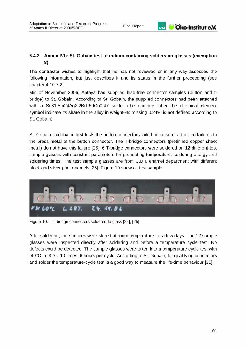
Adaptation to Scientific and Technical Progress of Annex II Directive 2000/53/EC Final Report
101
6.4.2 Annex IVb: St. Gobain test of indium-containing solders on glasses (exemption 8)
The contractor wishes to highlight that he has not reviewed or in any way assessed the following information, but just describes it and its status in the further proceeding (see chapter 4.10.7.2).
Mid of November 2006, Antaya had supplied lead-free connector samples (button and t-bridge) to St. Gobain. According to St. Gobain, the supplied connectors had been attached with a Sn81.5In24Ag2.2Bi1.59Cu0.47 solder (the numbers after the chemical element symbol indicate its share in the alloy in weight-%; missing 0.24% is not defined according to St. Gobain).
St. Gobain said that in first tests the button connectors failed because of adhesion failures to the brass metal of the button connector. The T-bridge connectors (pretinned copper sheet metal) do not have this failure [25]. 6 T-bridge connectors were soldered on 12 different test sample glasses with constant parameters for preheating temperature, soldering energy and soldering times. The test sample glasses are from C.D.I. enamel department with different black and silver print enamels [25]. Figure 10 shows a test sample.
Figure 10: T-bridge connectors soldered to glass [24], [25]
After soldering, the samples were stored at room temperature for a few days. The 12 sample glasses were inspected directly after soldering and before a temperature cycle test. No defects could be detected. The sample glasses were taken into a temperature cycle test with -40°C to 90°C, 10 times, 6 hours per cycle. According to St. Gobain, for qualifying connectors and solder the temperature-cycle test is a good way to measure the life-time behaviour [25].

Final Report Adaptation to scientific and technical progress
of Annex II Directive 2000/53/EC
102
Figure 11: Outer side of one sample glass with glass breakages of 6 connectors each with 2 soldered solder pads after temperature cycling from -40°C to 90°C, 10 times, 6 hours per cycle [24], [25]
In order to qualify the material, the test samples must not exhibit any failures. According to St. Gobain, however, 76 of 77 joints had glass breakages, as Figure 11 shows.
St. Gobain says it has reproduced the results in a joint test of Antaya and St. Gobain with a failure rate of 377 of 449 = 84%, and in an additional test by Antaya carried out by an external laboratory [24]. According to St. Gobain, the test results prove that the indium-containing solder used is not a viable substitute for lead-containing solders.
Antaya agrees to this conclusion, but says that for cost reasons, suppliers urged them to start with the lowest indium content solders. Antaya insisted that solders with higher indium contents would pass all necessary tests and hence are appropriate substitutes for lead-containing solders in the respective on-glass applications.
As a conclusion from the above tests and the stakeholders’ interpretations, it can be stated that at least the indium solders with only 24% of indium are not a viable option in the tested applications. Any further testing thus can start with higher indium content solders.
6.4.3 Annex IVc: Test documents as provided by Antaya
The following test results were submitted by Antaya [50].
The contractor wishes to highlight that he has not reviewed or in any way assessed this information and that it was not part of the review process due to the ongoing discussion about a test and application program between the stakeholders (see chapter 4.10.7.2).

Adaptation to Scientific and Technical Progress of Annex II Directive 2000/53/EC Final Report
103

Final Report Adaptation to scientific and technical progress
of Annex II Directive 2000/53/EC
104
Adaptation to Scientific and Technical Progress of Annex II Directive 2000/53/EC Final Report
105

Final Report Adaptation to scientific and technical progress
of Annex II Directive 2000/53/EC
106

Adaptation to Scientific and Technical Progress of Annex II Directive 2000/53/EC Final Report
107

Final Report Adaptation to scientific and technical progress
of Annex II Directive 2000/53/EC
108

Adaptation to Scientific and Technical Progress of Annex II Directive 2000/53/EC Final Report
109

Final Report Adaptation to scientific and technical progress
of Annex II Directive 2000/53/EC
110

Adaptation to Scientific and Technical Progress of Annex II Directive 2000/53/EC Final Report
111
Additionally to the above tests, Antaya has submitted the following document on the use of lead-free indium-containing solders in cars in the US (excerpt from [29] in section 4.10.9):
Letter dated October 30th, 2007 from PPG Industries to Antaya Technologies Corporation:
“As discussed yesterday the following is a brief summary of our experience using Antaya lead free solder on annealed glass for windshield applications.
The solder composition used was: 30% Sn, 65% In, 0.5% Cu, and 4.5% Ag. Our reason for using this solder versus those commonly used by our OEM glass fabricating division was two fold. First, since we were soldering to silver screened on annealed glass rather than tempered products, we wanted a low melting temperature solder to reduce the risk of damage to the silver and glass.
Secondly, cold shock testing indicated solder joints made with indium based solder were much less likely to develop surface vents that could lead to breakage.
Our first use of this solder was on the GM "U" Van or APV Van as it came to be known. We had a silver circuit screened on the #4 surface of the windshield near the top edge at about the mid point. The screened circuit was a part of an integrated system that replaced the radio antenna. A connector tab that had a crimped wire lead for connecting in the vehicle was soldered to the silver. This design was in use from 1999 to about 2001 or 2002.

Final Report Adaptation to scientific and technical progress
of Annex II Directive 2000/53/EC
112
Our second use of indium solder was for the Ford "T" Bird windshield that had a heated wiper circuit along the bottom edge of the part. This vehicle was built from 2002MY to 2005MY or only about three years. The indium solder composition was used for the exact same reasons as for the GM APV windshield. As you know this was a relatively low volume vehicle with less than 70,000 being built in total.
PPG has participated in GM's warranty reduction programs for many years and I can report that the APV Van windshield did not incur detached connectors or result in breakage that came to either GM's or to my attention. They have what they term an "early warning system" that analyzes early warranty data and highlights for follow up any problems or concerns so they can be quickly corrected. We also have access to GM's warranty data base and monitor each of the parts we supply for the same reason.
We did not have an active warranty data sharing system in place with Ford but relied on them to notify us if their data indicated there was a problem with the parts we supplied. As with GM, we did not receive notification of any soldering or breakage issues on the T Bird windshield during the time it was in production.“

Adaptation to Scientific and Technical Progress of Annex II Directive 2000/53/EC Final Report
113
6.5 Annex V: Additional information regarding exemption no. 11
Table 13: Applications of lead-containing ceramics in vehicles [52]
Current applications Effects of using the current applications
Negative impacts by substitution
Engine Section Parts Engine Control (knocking)
Oxygen Sensor Speedometer Controller (Clock)
ABS ’’ Driving Operations Sonar Controller
Air Bag Controller (Clock)
Car Radio/Audio CD/MD Controller (Clock)
Car Navigation CD/DVD/HDD Controller (Clock)
Remote Control (Clock) Anti-Theft Alarm System Controller (Clock)
Keyless Entry Receiving (Controller)
Cer
amic
reso
nato
rs
General Purpose PC Clock
Piezo ceramics application Lead piezoelectric ceramics can contribute to the realization of high grade electronic control for improving energy saving, safety and comfort in vehicles due to its excellent frequency stability and oscillation characteristics
Because the frequency stability of lead-free piezoelectric ceramics with Bi layer-structured compounds or tungsten-bronze structures suggested as alternative candidates is worse than that of piezoelectric ceramics containing lead, and oscillation characteristics are also inferior, it is difficult to achieve high grade electronic control for vehicles.
Car Radio/Audio AM Filter FM Filter
Car Navigation TV Filter
Cer
amic
filte
rs
Keyless Entry AM Filter
Piezo ceramics application As lead piezoelectric ceramics has superior frequency accuracy and thermal stability, high reliability information communication between electronic equipment in the vehicle can be achieved and it can contribute to improve energy saving, safety and comfort through the advancement of car electronics.
Lead-free piezoelectric ceramics with Bi layer-structured compounds or tungsten-bronze structures suggested as alternative candidates have poorer frequency accuracy and thermal stability than lead piezoelectric ceramics not being able to improve the reliability of information and communication between electronic equipment in the vehicle. Therefore, it is not possible to contribute with energy conservation, safety and comfort through the advancement of car electronics.

Final Report Adaptation to scientific and technical progress
of Annex II Directive 2000/53/EC
114
Current applications Effects of using the current applications
Negative impacts by substitution
Speedometer For alarms, sirens
Driving Operations ’’
General Purpose Buzzer
Pie
zoel
ectri
c bu
zzer
s
Piezo ceramics application Lead piezoelectric ceramics can produce high sound pressure under low voltage, and the mechanical operation part has a simple structure set to a minimum due to its small number of components. Therefore it can contribute with reduction of the number of set components, secure long-term reliability and low power consumption.
As lead-free piezoelectric ceramics has worse piezoelectric properties when compared to those containing lead, this will lead to the increase of power consumption.
Engine Section Parts
Knock Sensor Load Sensor
ABS Acceleration Sensor/Shock Sensor
Driving Operations Rear Side Sonar Corner Sensor
Air Bag Acceleration Sensor/Shock Sensor
Car Navigation
Angular Rate Sensor Shock Sensor for HDD
Cer
amic
sen
sors
Anti-Theft Alarm System Acceleration Sensor Microphone
Piezo ceramics application As lead piezoelectric ceramics has excellent piezoelectric characteristics, small size, high-functionality sensors can be achieved. As a result, it becomes possible to contribute to the realization of high grade electronic control for improving energy saving, safety and comfort of the vehicle.
There are concerns of product size enlargement and insufficiency of reliability due to poor piezoelectric characteristics in non-lead piezoelectric ceramics. As a result, it becomes difficult to achieve a high grade electronic control of the vehicle.
Engine Section Parts
For Fuel Injection
Act
uato
rs
General Purpose Mechanical Operations
Piezo ceramics application
There are concerns of product size enlargement and insufficiency of reliability due to poor piezoelectric characteristics in non-lead piezoelectric ceramics. As a result, it becomes difficult to achieve a high grade electronic control of the vehicle.
Engine Section Parts
Overheating Detector
Air bag Current Overflow Protection
Car Radio/Car Audio
Overheating Detector Current Overflow
Protection Keyless Entry ’’
General Purpose ’’ Heater Heater with Control
Function
PTC
cer
amic
s (T
herm
isto
rs)
PTC ceramics application As lead PTC ceramics possesses self thermal control functions, it presents high reliability and safety.
Lead-free PTC materials possess poorer reliability and safety than lead PTC ceramics, and this leads up to the increase in power consumption.

Adaptation to Scientific and Technical Progress of Annex II Directive 2000/53/EC Final Report
115
Table 14: Mass of lead in PZT components per vehicle [53]
Number per car
Weight of ceramics per
piece
Mass of lead *1 Subtotal Ave.
Ratio Ave. Mass
(pieces) (mg) (mg) (mg)Around Motor Resonator Engine Control 1 52 31 31.2 80% 25.0
Resonator Engine Control 3 5 3.3 9.9 30% 3.0
Resonator Oxigen Sensor 1 52 31 31.2 30% 9.4
Knocking Sensor Non-resonant type 1 5.000 2.500 2.500.0 90% 2.250.0
Knocking Sensor Resonant type 1 600 350 350.0 10% 35.0
Load Sensor 2 9.000 6.150 12.300.0 5% 615.0
Actuator Fuel Injection 4 10,000~16,000
6,500~10,000
26,000~40,000
20% 5,200~8,000
PTC Thermistors Over heat sensing 1 3.87 0.14 0.1 10% 0.0
PTC Thermistors Over heat sensing 1 8.82 0.35 0.3 10% 0.0
Speed-o-meter Resonator 1 52 31 31.2 80% 25.0
Piezo Sounder Warning・Information 1 81 53 53.0 50% 26.5
ABS G Sensor
Resonator 1 52 31 31.2 70% 21.8
Resonator 1 5 3.3 3.3 70% 2.3
Warning Back Soner US Microphone 2 110 70 140.0 10% 14.0
Corner Soner US Microphone 3 110 70 210.0 10% 21.0
Piezo Sounder Back Buzzer 1 610 430 430.0 90% 387.0
Resonator 4 52 31 124.8 90% 112.3
Resonator 4 5 3.3 13.2 50% 6.6
Safety G SensorShock Sensor Failsafe 4 158 72 288.0 70% 201.6
Air Bag Resonator 4 5 3.3 13.2 50% 6.6
Resonator 2 52 31 62.4 70% 43.7
PTC Thermistors Circuit Protection 1 249.00 18.00 18.0 5% 0.9
Car Radio Filter AM Radder Filter 1 540 320 320.0 90% 288.0
Car Stereo Filter FM Filter 2 40 26 52.0 90% 46.8
Resonator CD/MD 1 52 31 31.2 50% 15.6
Resonator CD/MD 1 5 3.3 3.3 50% 1.7
PTC Thermistors Over heat sensing 1 12.64 0.23 0.2 20% 0.0
PTC Thermistors Circuit Protection 1 145.91 10.84 10.8 20% 2.2
Car Navigation Filter
Gyroscope Angular Rate 2 1 1 1.2 10% 0.1
Resonator CD/DVD/HDD 3 52 31 93.6 10% 9.4
Resonator System Clock 2 30 20 40.0 30% 12.0
Resonator CD/DVD/HDD 1 5 3.3 3.3 10% 0.3
TV Filter TV functions 1 33 20 20.0 10% 2.0
G Sensor HDD 1 10%
Burglar Alerm G Sensor Vibration Sensing
US Mirophone 2 150 100 200.0 20% 40.0
Piezo Sounder Alarm 1 610 430 430.0 20% 86.0
Resonator 1 52 31 31.2 20% 6.2
Keyless Entry Filter AM Radder filter 1 540 320 320.0 30% 96.0
*2 Filter FM Filter 1 33 20 20.0 60% 12.0
Discriminator 1 150 105 105.0 30% 31.5
Resonator 1 30 20 20.0 30% 6.0
PTC Thermistors Circuit Protection 1 139.68 6.00 6.0 5% 0.3
General Purpose Resonator Clock of MPU *3 30 20
Filter AM filter *3 200 140
AM Radder filter *3 540 320
FM Filter *3 33 20
TV/VTR *3 33 20
Piezo Sounder Buzzer/Speaker *3 600 420
Piezo Transformer LCD 1 6.000 4.000 4.000.0 10% 400.0
PTC Thermistors Circuit Protection(Door mirror) 4 38.00 2.90 11.60 20% 2.3
PTC Thermistors For Heater 10 7780.00 1.770.00 17.700.00 5% 885.0
Actuator Mechanical movement *3 350 200
Actuator Mechanical movement *3 20 12
Shock sensor Rolling detection(Tire Pressure monitor)
80061+alfa 13750+alfa
General Despriction or DetailsApplication
*3
*3
Name of Parts
*3
*3
*3
*3
*3
*3*3*3*3*3
*1 mass of pure metal lead. *2 key(controller) of keyless entry is not counted. *3 value differs depending on the specification.

Final Report Adaptation to scientific and technical progress
of Annex II Directive 2000/53/EC
116
6.6 Annex VII: Questions with regard to exemption no. 17
Questions to stakeholders supporting the extension of the exemption until 2010:
1) Please provide a roadmap showing that you initially intended to meet the expiry date of 1 December 2008 and explaining why you had to adapt it to 2010 (what were the technical reasons, what is the current status of R&D, why is substitution currently not feasible,...). Also explain what the missing steps are before alternative technologies can be put in place in EV on the EU market.
2) Which alternative technology is planned to be used in batteries for EV? Explain its state of R&D. Has the technology itself been validated and industry now needs to develop according vehicles? Or is technology validation still taking place? What is the state of play?
3) Please state why apparently previous assessments already came to the conclusion some years ago that substitution is technically feasible and still no phase-out of NiCd batteries in EV has taken place until now?
4) What is the state of play concerning the development and use in EV series production of Li-ion batteries?
5) Is the argument of legal consistency with the Batteries Directive still valid? If so, please explain in further detail.
6) Please send us the latest available data on i) total amount of Cd involved in EV in the EU, ii) total and relative amount of Cd in a single NiCd battery for an EV, iii) total and relative amount of EV using NiCd in relation to total vehicle fleet in EU and iv) total and relative amount of EV on EU market using alternative technologies (and share by technology if possible).
Questions to stakeholders supporting the expiry of the current exemption as foreseen by 31 December 2008 (except for replacement parts):
1) Can you provide any supporting evidence that substitution is feasible at a commercial level and for series production for vehicles put on the market in the EU?
2) How many EV (in total and in percentage of all EV) using alternative battery technologies are put on the market in the EU today? What is the alternative technology they use (please state percentages if possible)?
3) What do you consider to be hindrances for the automotive industry not to have substituted NiCd fully by 31 December 2008?
4) What is your position concerning the argument on legal consistency with the Batteries Directive?
5) Do you consider that Cd will be phased-out fully and thus may have a negative market value in future? Or is this already the case? Do you think this would have negative consequences on recycling of NiCd from ELV?