adafruit 3.5 320x480 color tft touchscreen breakout · adafruit 3.5" 320x480 color tft...
TRANSCRIPT
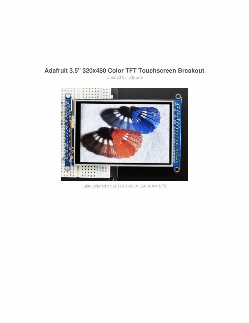
Adafruit 3.5" 320x480 Color TFT Touchscreen BreakoutCreated by lady ada
Last updated on 2017-01-30 01:59:14 AM UTC

23779
1111121314
16161618
222329293233363941424244464646
Guide Contents
Guide ContentsOverviewPinoutsSPI Mode8-Bit ModeWiring & TestAssembling Header
Prepare the header strip:Add the breakout board:Add the breakout board:
8-Bit Wiring & Test8-Bit Wiring
Part 1 - Power & backlight testPart 2 - Data Bus Lines
8-Bit Library InstallPrepare TFTLCD LibrarySPI Wiring & TestSPI Mode JumpersWiringInstall Adafruit HX8357 TFT LibraryBitmaps (SPI Mode)Adafruit GFX libraryTouchscreenDownload LibraryTouchscreen Paint (SPI mode)Touchscreen Paint (8-Bit mode)DownloadsDatasheets & FilesSchematic and PCB Print
© Adafruit Industries https://learn.adafruit.com/adafruit-3-5-color-320x480-tft-touchscreen-breakout
Page 2 of 47

Overview
Add some jazz & pizazz to your project with a color touchscreen LCD. This TFT display isbig (3.5" diagonal) bright (6 white-LED backlight) and colorful! 480x320 pixels withindividual RGB pixel control, this has way more resolution than a black and white 128x64display, and double our 2.8" TFT. As a bonus, this display has a resistive touchscreenattached to it already, so you can detect finger presses anywhere on the screen.
© Adafruit Industries https://learn.adafruit.com/adafruit-3-5-color-320x480-tft-touchscreen-breakout
Page 3 of 47
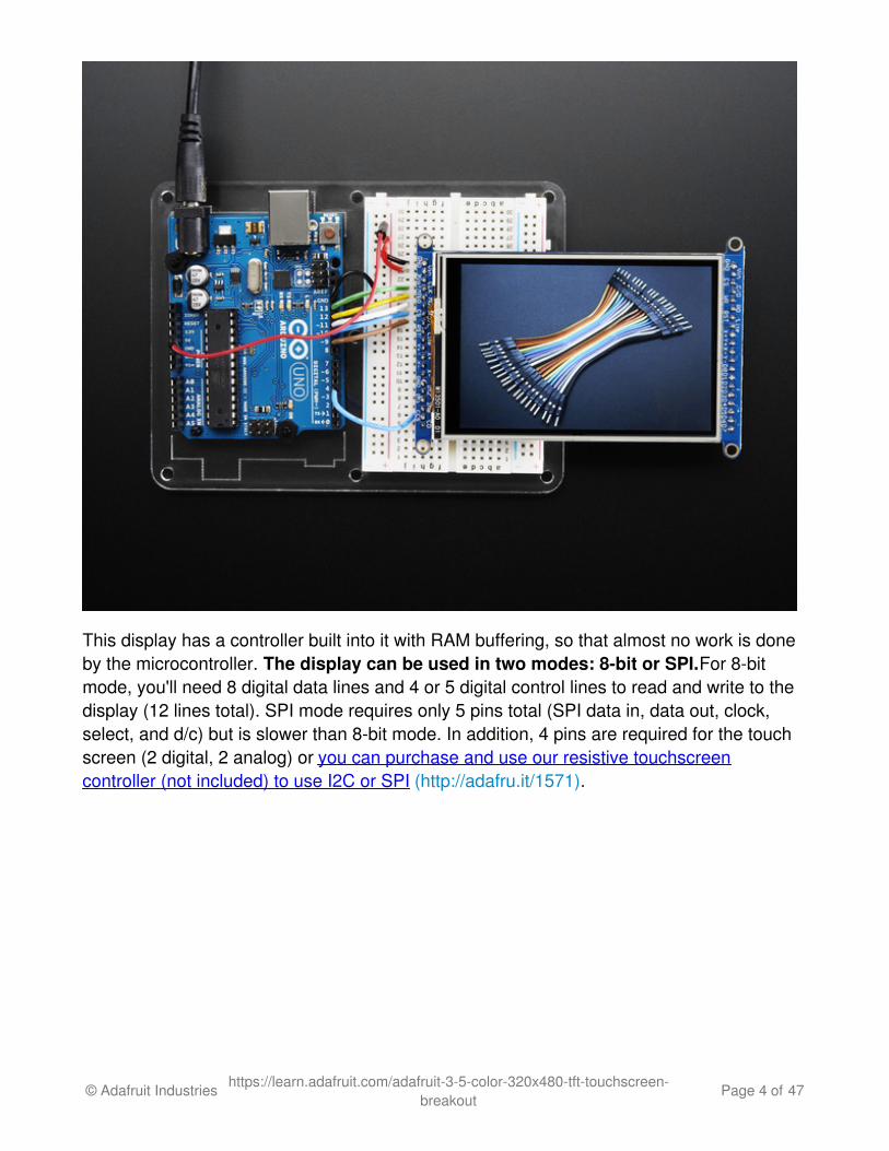
This display has a controller built into it with RAM buffering, so that almost no work is doneby the microcontroller. The display can be used in two modes: 8-bit or SPI. For 8-bitmode, you'll need 8 digital data lines and 4 or 5 digital control lines to read and write to thedisplay (12 lines total). SPI mode requires only 5 pins total (SPI data in, data out, clock,select, and d/c) but is slower than 8-bit mode. In addition, 4 pins are required for the touchscreen (2 digital, 2 analog) or you can purchase and use our resistive touchscreencontroller (not included) to use I2C or SPI (http://adafru.it/1571).
© Adafruit Industries https://learn.adafruit.com/adafruit-3-5-color-320x480-tft-touchscreen-breakout
Page 4 of 47

Of course, we wouldn't just leave you with a datasheet and a "good luck!". For 8-bitinterface fans we've written a full open source graphics library that can draw pixels, lines,rectangles, circles, text, and more (http://adafru.it/aHk). For SPI users, we have a library aswell (http://adafru.it/dQW), its separate from the 8-bit library since both versions are heavilyoptimized. We also have a touch screen library that detects x, y and z(pressure) (http://adafru.it/aT1) and example code to demonstrate all of it.
© Adafruit Industries https://learn.adafruit.com/adafruit-3-5-color-320x480-tft-touchscreen-breakout
Page 5 of 47

© Adafruit Industries https://learn.adafruit.com/adafruit-3-5-color-320x480-tft-touchscreen-breakout
Page 6 of 47

Pinouts
The 3.5" TFT display on this breakout supports many different modes - so many that thedisplay itself has 50 pins. However, we think most people really only use 2 different modes,either "SPI" mode or 8-bit mode. Each 'side' of the display has all the pins required for thatmode. You can switch between modes, by rewiring the display, but it cannot be used in twomodes at the same time!
All logic pins, both 8-bit and SPI sides, are 3-5V logic level compatible, the 74LVX245 chipson the back perform fast level shifting so you can use either kind of logic levels. If there'sdata output, the levels are at at 3.3V
SPI Mode
© Adafruit Industries https://learn.adafruit.com/adafruit-3-5-color-320x480-tft-touchscreen-breakout
Page 7 of 47

This is what we think will be a popular mode when speed is not of the utmost importance. Itdoesn't use as many pins (only 4 to draw on the TFT if you skip the MISO pin), is fairlyflexible, and easy to port to various microcontrollers. It also allows using a microSD cardsocket on the same SPI bus. However, its slower than parallel 8-bit mode because youhave to send each bit at a time instead of 8-bits at a time. Tradeoffs!
GND - this is the power and signal ground pin3-5V / Vin - this is the power pin, connect to 3-5VDC - it has reverse polarityprotection but try to wire it right!3.3Vout - this is the 3.3V output from the onboard regulatorCLK - this is the SPI clock input pinMISO - this is the SPI Master In Slave Out pin, its used for the SD card mostly, and fordebugging the TFT display. It isn't necessary for using the TFT display which is write-onlyMOSI - this is the SPI Master Out Slave In pin, it is used to send data from themicrocontroller to the SD card and/or TFTCS - this is the TFT SPI chip select pinD/C - this is the TFT SPI data or command selector pinRST - this is the TFT reset pin. There's auto-reset circuitry on the breakout so this pinis not required but it can be helpful sometimes to reset the TFT if your setup is notalways resetting cleanly. Connect to ground to reset the TFTLite - this is the PWM input for the backlight control. It is by default pulled high(backlight on) you can PWM at any frequency or pull down to turn the backlight offY+ X+ Y- X- these are the 4 resistive touch screen pads, which can be read withanalog pins to determine touch points. They are completely separated from the TFTelectrically (the overlay is glued on top)IM2 IM1 IM0 - these are interface control set pins. In general these breakouts aren'tused, and instead the onboard jumpers are used to fix the interface to SPI or 8-bit.However, we break these out for advanced use and also for our test proceduresCard CS / CCS - this is the SD card chip select, used if you want to read from the SDcard.Card Detect / CD - this is the SD card detect pin, it floats when a card is inserted,
© Adafruit Industries https://learn.adafruit.com/adafruit-3-5-color-320x480-tft-touchscreen-breakout
Page 8 of 47

and tied to ground when the card is not inserted. We don't use this in our code butyou can use this as a switch to detect if an SD card is in place without trying toelectrically query it. Don't forget to use a pullup on this pin if so!
8-Bit ModeThis mode is for when you have lots of pins and want more speed. In this mode we send 8bits at a time, so it needs way more pins, 12 or so (8 bits plus 4 control)! If yourmicrocontroller
GND - this is the power and signal ground pin3-5V (Vin)- this is the power pin, connect to 3-5VDC - it has reverse polarityprotection but try to wire it right!CS - this is the TFT 8-bit chip select pin (it is also tied to the SPI mode CS pin)C/D - this is the TFT 8-bit data or command selector pin (it is also tied to the SPImode C/D pin)WR - this is the TFT 8-bit write strobe pin. It is also connected to the SPI CLK pinRD - this is the TFT 8-bit read strobe pin. You may not need this pin if you don't wantto read data from the displayRST - this is the TFT reset pin. There's auto-reset circuitry on the breakout so this pinis not required but it can be helpful sometimes to reset the TFT if your setup is notalways resetting cleanly. Connect to ground to reset the TFTBacklite - this is the PWM input for the backlight control. It is by default pulled high(backlight on) you can PWM at any frequency or pull down to turn the backlight offY+ X+ Y- X- these are the 4 resistive touch screen pads, which can be read withanalog pins to determine touch points. They are completely separated from the TFTelectrically (the overlay is glued on top)D0 thru D7 - these are the 8 bits of parallel data sent to the TFT in 8-bit mode. D0 isthe least-significant-bit and D7 is the MSB
© Adafruit Industries https://learn.adafruit.com/adafruit-3-5-color-320x480-tft-touchscreen-breakout
Page 9 of 47

© Adafruit Industries https://learn.adafruit.com/adafruit-3-5-color-320x480-tft-touchscreen-breakout
Page 10 of 47

Wiring & TestWe tried to make this TFT breakout useful for both high-pin microcontrollers that canhandle 8-bit data transfer modes as well as low-pincount micros like the Arduino UNO andLeonardo that are OK with SPI.
Essentially, the tradeoff is pins for speed. SPI is about 2-4 times slower than 8-bit mode,but that may not matter for basic graphics!
In addition, SPI mode has the benefit of being able to use the onboard microSD cardsocket for reading images. We don't have support for this in 8-bit mode so if you want tohave an all-in-one image viewer type application, use SPI!
Assembling HeaderEither way, if you're using a breadboard, you'll need to solder header onto one or two ofthe sides. The procedure is the same for both sides
© Adafruit Industries https://learn.adafruit.com/adafruit-3-5-color-320x480-tft-touchscreen-breakout
Page 11 of 47

Prepare the headerstrip:
Cut the strip to length ifnecessary. It will be easier tosolder if you insert it into abreadboard - long pins down
© Adafruit Industries https://learn.adafruit.com/adafruit-3-5-color-320x480-tft-touchscreen-breakout
Page 12 of 47

Add the breakoutboard:
Place the breakout board overthe pins so that the short pinspoke through the breakout pads
© Adafruit Industries https://learn.adafruit.com/adafruit-3-5-color-320x480-tft-touchscreen-breakout
Page 13 of 47

Add the breakoutboard:
Place the breakout board overthe pins so that the short pinspoke through the breakout pads
© Adafruit Industries https://learn.adafruit.com/adafruit-3-5-color-320x480-tft-touchscreen-breakout
Page 14 of 47

You're done! Check your solderjoints visually and continue ontothe next steps
© Adafruit Industries https://learn.adafruit.com/adafruit-3-5-color-320x480-tft-touchscreen-breakout
Page 15 of 47
8-Bit Wiring & Test
8-Bit WiringWiring up the 8-bit mode is kind of a pain, so we really only recommend doing it for UNO(which we show) and Mega (which we describe, and is pretty easy since its 8 pins in a row).Anything else, like a Leonardo or Micro, we strongly recommend going with SPI mode sincewe don't have an example for that. Any other kind of 'Arduino compatible' that isn't an Uno,try SPI first. The 8-bit mode is hand-tweaked in the Adafruit_TFTLCD pin_magic.h file. Itsreally only for advanced users who are totally cool with figuring out bitmasks for variousports & pins.
Really, we'll show how to do the UNO but anything else? go with SPI!
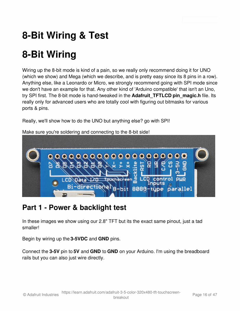
Make sure you're soldering and connecting to the 8-bit side!
Part 1 - Power & backlight test
In these images we show using our 2.8" TFT but its the exact same pinout, just a tadsmaller!
Begin by wiring up the 3-5VDC and GND pins.
Connect the 3-5V pin to 5V and GND to GND on your Arduino. I'm using the breadboardrails but you can also just wire directly.
© Adafruit Industries https://learn.adafruit.com/adafruit-3-5-color-320x480-tft-touchscreen-breakout
Page 16 of 47

Power it up and you should see the white backlight come on
© Adafruit Industries https://learn.adafruit.com/adafruit-3-5-color-320x480-tft-touchscreen-breakout
Page 17 of 47
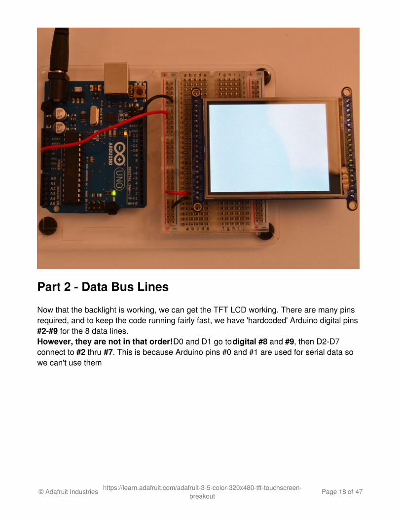
Part 2 - Data Bus Lines
Now that the backlight is working, we can get the TFT LCD working. There are many pinsrequired, and to keep the code running fairly fast, we have 'hardcoded' Arduino digital pins#2-#9 for the 8 data lines.However, they are not in that order! D0 and D1 go to digital #8 and #9, then D2-D7connect to #2 thru #7. This is because Arduino pins #0 and #1 are used for serial data sowe can't use them
© Adafruit Industries https://learn.adafruit.com/adafruit-3-5-color-320x480-tft-touchscreen-breakout
Page 18 of 47

Begin by connecting D0 and D1 to digital #8 and 9 respectively as seen above. If you'reusing a Mega, connect the TFT Data Pins D0-D1 to Mega pins #22-23, in that order. ThoseMega pins are on the 'double' header.
© Adafruit Industries https://learn.adafruit.com/adafruit-3-5-color-320x480-tft-touchscreen-breakout
Page 19 of 47

Now you can connect the remaining 6 pins over. Connect D2-D7 on the TFT pins to digital2 thru 7 in that order. If you're using a Mega, connect the TFT Data Pins D2-D7 to Megapins #24-29, in that order. Those Mega pins are on the 'double' header.
© Adafruit Industries https://learn.adafruit.com/adafruit-3-5-color-320x480-tft-touchscreen-breakout
Page 20 of 47

In addition to the 8 data lines, you'll also need 4 or 5 control lines. These can later bereassigned to any digital pins, they're just what we have in the tutorial by default.
Connect the third pin CS (Chip Select) to Analog 3Connect the fourth pin C/D (Command/Data) to Analog 2Connect the fifth pin WR (Write) to Analog 1Connect the sixth pin RD (Read) to Analog 0
© Adafruit Industries https://learn.adafruit.com/adafruit-3-5-color-320x480-tft-touchscreen-breakout
Page 21 of 47
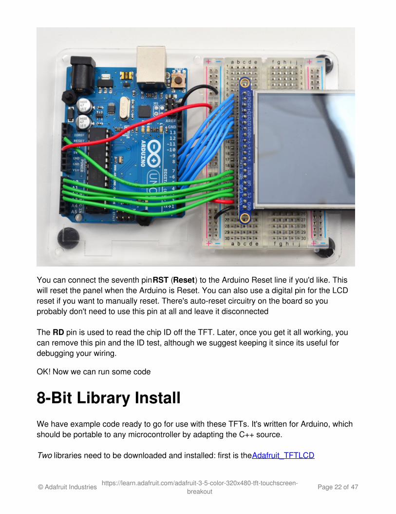
You can connect the seventh pin RST (Reset) to the Arduino Reset line if you'd like. Thiswill reset the panel when the Arduino is Reset. You can also use a digital pin for the LCDreset if you want to manually reset. There's auto-reset circuitry on the board so youprobably don't need to use this pin at all and leave it disconnected
The RD pin is used to read the chip ID off the TFT. Later, once you get it all working, youcan remove this pin and the ID test, although we suggest keeping it since its useful fordebugging your wiring.
OK! Now we can run some code
8-Bit Library InstallWe have example code ready to go for use with these TFTs. It's written for Arduino, whichshould be portable to any microcontroller by adapting the C++ source.
Two libraries need to be downloaded and installed: first is the Adafruit_TFTLCD
© Adafruit Industries https://learn.adafruit.com/adafruit-3-5-color-320x480-tft-touchscreen-breakout
Page 22 of 47

library (http://adafru.it/aHk) (this contains the low-level code specific to this device), andsecond is the Adafruit GFX Library (http://adafru.it/aJa) (which handles graphics operationscommon to many displays we carry). If you have Adafruit_GFX already, make sure its themost recent version since we've made updates for better performance
Download Adafruit_TFTLCD LIbraryhttp://adafru.it/dcWDownload Adafruit_GFX Libraryhttp://adafru.it/cBB
Download both ZIP files, uncompress and rename the folders to Adafruit_TFTLCD(contains Adafruit_TFTLCD.cpp and .h) and Adafruit_GFX (contains Adafruit_GFX.cppand .h) respectively. Then place them inside your Arduino libraries folder and restart theArduino IDE. If this is all unfamiliar, we have a tutorial introducing Arduino library conceptsand installation (http://adafru.it/aYM).
Prepare TFTLCD LibraryIn the Adafruit_TFTLCD Library folder, you may need to edit Adafruit_TFTLCD.h. Onabout line 12, you will see
#define USE_ADAFRUIT_SHIELD_PINOUT
Make sure this line is commented out with a // in front (it should but if you're having issues,its worth checking.
Next up, we originally designed this library for 320x240 TFTs. Since this is a 480x320, we have to adjust the size the library is expecting. Open up Adafruit_TFTLCD.cpp and findthese lines:
© Adafruit Industries https://learn.adafruit.com/adafruit-3-5-color-320x480-tft-touchscreen-breakout
Page 23 of 47

Comment out the 240 and 320 lines, and uncomment the 320 and 480 lines:
© Adafruit Industries https://learn.adafruit.com/adafruit-3-5-color-320x480-tft-touchscreen-breakout
Page 24 of 47

Save it, now you can upload the demo!
After restarting the Arduino software, you should see a new example folder calledAdafruit_TFTLCD and inside, an example called graphicstest. Upload that sketch to yourArduino.
© Adafruit Industries https://learn.adafruit.com/adafruit-3-5-color-320x480-tft-touchscreen-breakout
Page 25 of 47

You may need to press the Reset button to reset the Arduino and TFT. You should see acollection of graphical tests draw out on the TFT.
(The images below shows SPI wiring but the graphical output should be similar!)
© Adafruit Industries https://learn.adafruit.com/adafruit-3-5-color-320x480-tft-touchscreen-breakout
Page 26 of 47

If you're having difficulties, check the serial console.The first thing the sketch does is readthe driver code from the TFT. It should be 0x8357 (for the HX8357D controller inside)
© Adafruit Industries https://learn.adafruit.com/adafruit-3-5-color-320x480-tft-touchscreen-breakout
Page 27 of 47
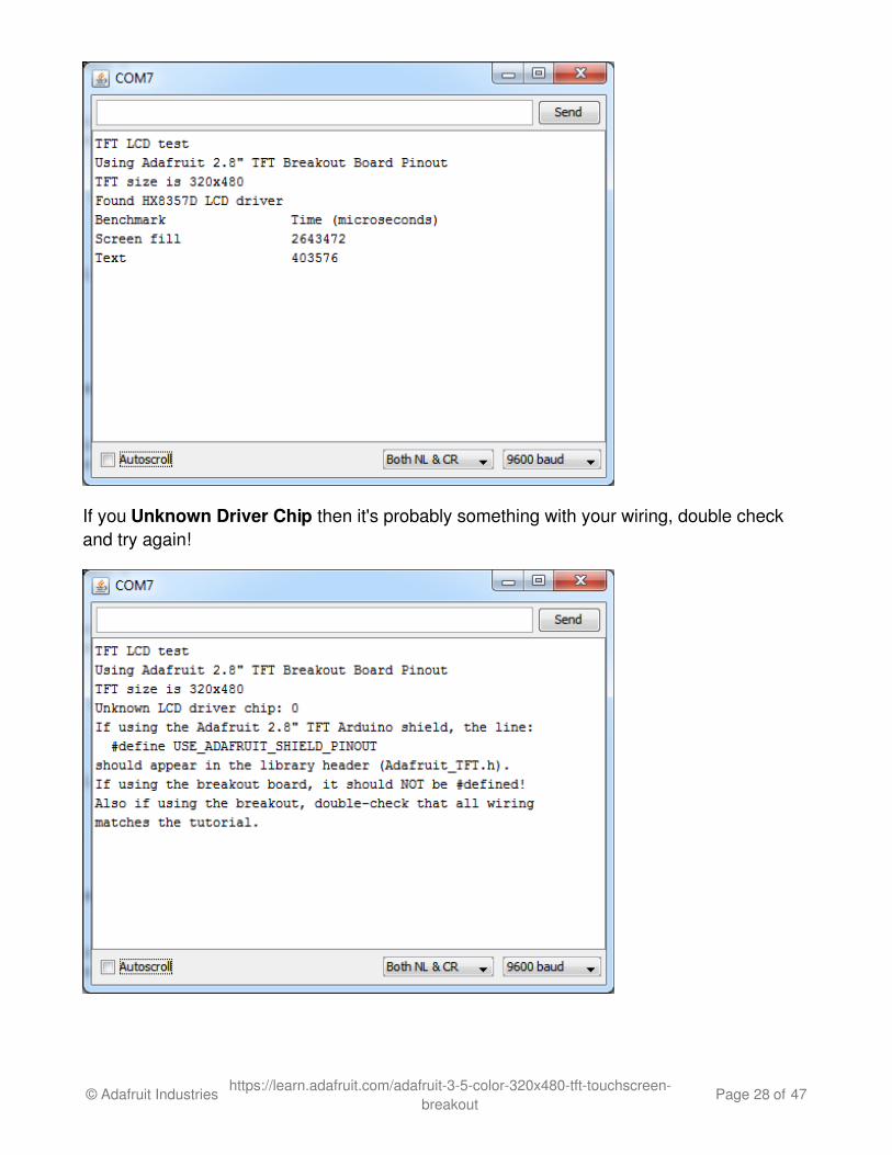
If you Unknown Driver Chip then it's probably something with your wiring, double checkand try again!
© Adafruit Industries https://learn.adafruit.com/adafruit-3-5-color-320x480-tft-touchscreen-breakout
Page 28 of 47

SPI Wiring & TestDon't forget, we're using the SPI interface side of the PCB!
SPI Mode JumpersBefore you start, we'll need to tell the display to put us in SPI mode so it will know whichpins to listen to. To do that, we have to connect the IM2 pin to 3.3V. The easiest way to dothat is to solder closed the IM2 jumper on the back of the PCB. Turn over the PCB and findthe solder jumper:
© Adafruit Industries https://learn.adafruit.com/adafruit-3-5-color-320x480-tft-touchscreen-breakout
Page 29 of 47

With your soldering iron, melt solder to close the jumper indicated IM2
© Adafruit Industries https://learn.adafruit.com/adafruit-3-5-color-320x480-tft-touchscreen-breakout
Page 30 of 47

© Adafruit Industries https://learn.adafruit.com/adafruit-3-5-color-320x480-tft-touchscreen-breakout
Page 31 of 47

If you really don't want to solder, you can also wire the breakout pin to the 3vo pin, justmake sure you don't tie it to 5V by accident! For that reason, we suggest going with thesolder-jumper route.
WiringWiring up the display in SPI mode is much easier than 8-bit mode since there's way fewerwires. Start by connecting the power pins
3-5V Vin connects to the Arduino 5V pinGND connects to Arduino groundCLK connects to SPI clock. On Arduino Uno/Duemilanove/328-based, thats Digital13. On Mega's, its Digital 52 and on Leonardo/Due its ICSP-3 (See SPI Connectionsfor more details (http://adafru.it/d5h))MISO connects to SPI MISO. On Arduino Uno/Duemilanove/328-based, thats Digital12. On Mega's, its Digital 50 and on Leonardo/Due its ICSP-1 (See SPI Connectionsfor more details (http://adafru.it/d5h))
© Adafruit Industries https://learn.adafruit.com/adafruit-3-5-color-320x480-tft-touchscreen-breakout
Page 32 of 47

MOSI connects to SPI MOSI. On Arduino Uno/Duemilanove/328-based, thats Digital11. On Mega's, its Digital 51 and on Leonardo/Due its ICSP-4 (See SPI Connectionsfor more details (http://adafru.it/d5h))CS connects to our SPI Chip Select pin. We'll be using Digital 10 but you can laterchange this to any pinD/C connects to our SPI data/command select pin. We'll be using Digital 9 but youcan later change this pin too.
That's it! You do not need to connect the RST or other pins for now.
Install Adafruit HX8357 TFT LibraryWe have example code ready to go for use with these TFTs. It's written for Arduino, whichshould be portable to any microcontroller by adapting the C++ source.
Two libraries need to be downloaded and installed: first is the Adafruit_HX8357library (http://adafru.it/dQW) (this contains the low-level code specific to this device), and
© Adafruit Industries https://learn.adafruit.com/adafruit-3-5-color-320x480-tft-touchscreen-breakout
Page 33 of 47
second is the Adafruit GFX Library (http://adafru.it/aJa) (which handles graphics operationscommon to many displays we carry). If you have Adafruit_GFX already, make sure its themost recent version since we've made updates for better performance
Download the Adafruit HX8357 Libraryhttp://adafru.it/dR0Download the Adafruit GFX Libraryhttp://adafru.it/cBB
Download both ZIP files, uncompress and rename the folders to Adafruit_HX8357(contains Adafruit_HX8357.cpp and .h) and Adafruit_GFX (contains Adafruit_GFX.cppand .h) respectively. Then place them inside your Arduino libraries folder and restart theArduino IDE. If this is all unfamiliar, we have a tutorial introducing Arduino library conceptsand installation (http://adafru.it/aYM).
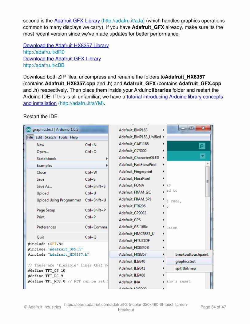
Restart the IDE
© Adafruit Industries https://learn.adafruit.com/adafruit-3-5-color-320x480-tft-touchscreen-breakout
Page 34 of 47

After restarting the Arduino software, you should see a new example folder calledAdafruit_HX8357 and inside, an example called graphicstest. Upload that sketch to yourArduino. You may need to press the Reset button to reset the arduino and TFT. Youshould see a collection of graphical tests draw out on the TFT.
If you're having difficulties, check the serial console.The first thing the sketch does is readthe driver configuration from the TFT, you should see the same numbers as below
If you did not connect up the MISO line to the TFT, you wont see the readconfiguation bytes so please make sure you connect up the MISO line for easydebugging! Once its all working, you can remove the MISO line
© Adafruit Industries https://learn.adafruit.com/adafruit-3-5-color-320x480-tft-touchscreen-breakout
Page 35 of 47

Bitmaps (SPI Mode)There is a built in microSD card slot into the breakout, and we can use that to load bitmapimages! You will need a microSD card formatted FAT16 or FAT32 (they almost always areby default).
Its really easy to draw bitmaps. However, this is only supported when talking to thedisplay in SPI mode, not 8-bit mode!
Find the jumpers.bmp file in the downloaded Arduino library
Copy jumpers.bmp into the base directory of a microSD card and insert it into the microSDsocket in the breakout.
You'll need to connect up the CCS pin to Digital 4 on your Arduino as well. See the imagebelow
© Adafruit Industries https://learn.adafruit.com/adafruit-3-5-color-320x480-tft-touchscreen-breakout
Page 36 of 47

You may want to try the SD library examples before continuing, especially one that lists allthe files on the SD card
Now upload the file->examples->Adafruit_HX8357->spitftbitmap example to yourArduino + breakout. You will see the jumper wires appear!
© Adafruit Industries https://learn.adafruit.com/adafruit-3-5-color-320x480-tft-touchscreen-breakout
Page 37 of 47

To make new bitmaps, make sure they are less than 320 by 480 pixels and save them in24-bit BMP format! They must be in 24-bit format, even if they are not 24-bit color as thatis the easiest format for the Arduino. You can rotate images using the setRotation()procedure
You can draw as many images as you want - dont forget the names must be less than 8characters long. Just copy the BMP drawing routines below loop() and call
bmpDraw(bmpfilename, x, y);
For each bitmap. They can be smaller than 320x480 and placed in any location on thescreen.
© Adafruit Industries https://learn.adafruit.com/adafruit-3-5-color-320x480-tft-touchscreen-breakout
Page 38 of 47

Adafruit GFX library
The Adafruit_GFX library for Arduino provides a common syntax and set of graphicsfunctions for all of our TFT, LCD and OLED displays. This allows Arduino sketches to easilybe adapted between display types with minimal fuss…and any new features, performanceimprovements and bug fixes will immediately apply across our complete offering of colordisplays.
The GFX library is what lets you draw points, lines, rectangles, round-rects, triangles, text,etc.
Check out our detailed tutorial here http://learn.adafruit.com/adafruit-gfx-graphics-library (http://adafru.it/aPx)
It covers the latest and greatest of the GFX library. The GFX library is used in both 8-bit
© Adafruit Industries https://learn.adafruit.com/adafruit-3-5-color-320x480-tft-touchscreen-breakout
Page 39 of 47
and SPI modes so the underlying commands (drawLine() for example) are identical!
© Adafruit Industries https://learn.adafruit.com/adafruit-3-5-color-320x480-tft-touchscreen-breakout
Page 40 of 47
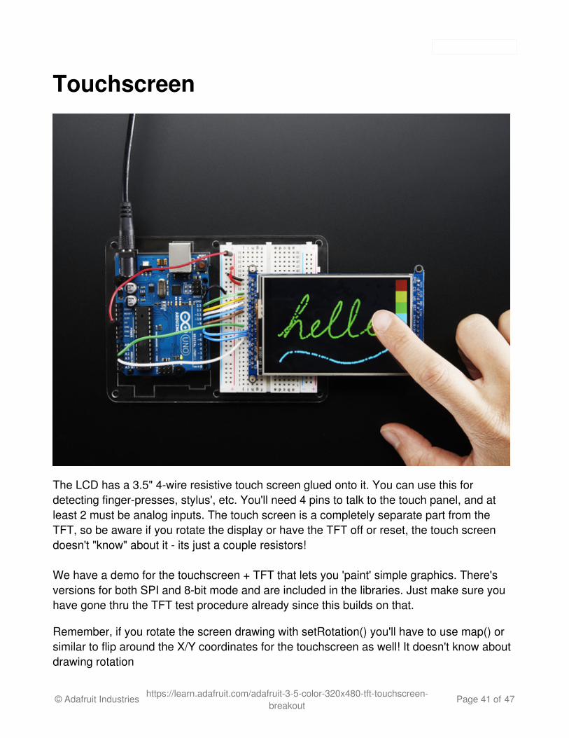
Touchscreen
The LCD has a 3.5" 4-wire resistive touch screen glued onto it. You can use this fordetecting finger-presses, stylus', etc. You'll need 4 pins to talk to the touch panel, and atleast 2 must be analog inputs. The touch screen is a completely separate part from theTFT, so be aware if you rotate the display or have the TFT off or reset, the touch screendoesn't "know" about it - its just a couple resistors!
We have a demo for the touchscreen + TFT that lets you 'paint' simple graphics. There'sversions for both SPI and 8-bit mode and are included in the libraries. Just make sure youhave gone thru the TFT test procedure already since this builds on that.
Remember, if you rotate the screen drawing with setRotation() you'll have to use map() orsimilar to flip around the X/Y coordinates for the touchscreen as well! It doesn't know aboutdrawing rotation
© Adafruit Industries https://learn.adafruit.com/adafruit-3-5-color-320x480-tft-touchscreen-breakout
Page 41 of 47

Download LibraryBegin by grabbing our analog/resistive touchscreen library from github (http://adafru.it/aT1)(or just click the download button)
Download Adafruit Touchscreen Libraryhttp://adafru.it/dd0
Touchscreen Paint (SPI mode)An additional 4 pins are required for the touchscreen. For the two analog pins, we'll use A2and A3. For the other two connections, you can pin any two digital pins but we'll be usingD8 and D7 since they are available.
Wire the additional 4 pins as follows:
Y+ to Arduino A2X+ to Arduino D8Y- to Arduino D7X- to Arduino A3
© Adafruit Industries https://learn.adafruit.com/adafruit-3-5-color-320x480-tft-touchscreen-breakout
Page 42 of 47
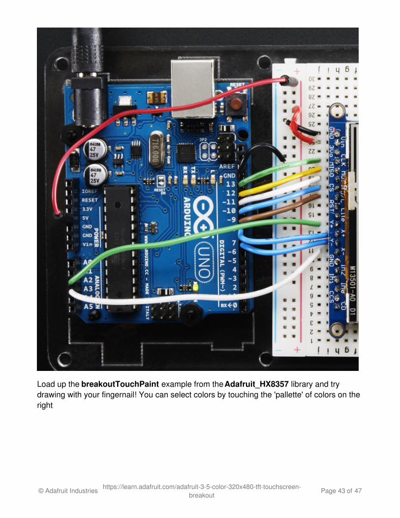
Load up the breakoutTouchPaint example from the Adafruit_HX8357 library and trydrawing with your fingernail! You can select colors by touching the 'pallette' of colors on theright
© Adafruit Industries https://learn.adafruit.com/adafruit-3-5-color-320x480-tft-touchscreen-breakout
Page 43 of 47
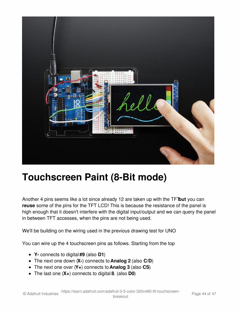
Touchscreen Paint (8-Bit mode)
Another 4 pins seems like a lot since already 12 are taken up with the TFT but you canreuse some of the pins for the TFT LCD! This is because the resistance of the panel ishigh enough that it doesn't interfere with the digital input/output and we can query the panelin between TFT accesses, when the pins are not being used.
We'll be building on the wiring used in the previous drawing test for UNO
You can wire up the 4 touchscreen pins as follows. Starting from the top
Y- connects to digital #9 (also D1)The next one down (X-) connects to Analog 2 (also C/D)The next one over (Y+) connects to Analog 3 (also CS)The last one (X+) connects to digital 8. (also D0)
© Adafruit Industries https://learn.adafruit.com/adafruit-3-5-color-320x480-tft-touchscreen-breakout
Page 44 of 47

The X- and Y+ pins pretty much have to connect to those analog pins (or to analog 4/5) butY-/X+ can connect to any digital or analog pins.
The image below shows the wiring, its for the 2.8" TFT but its the same wiring setup
Load up the tftpaint example from the Adafruit_TFTLCD library and try drawing with yourfingernail! You can select colors by touching the 'pallette' of colors on the right
© Adafruit Industries https://learn.adafruit.com/adafruit-3-5-color-320x480-tft-touchscreen-breakout
Page 45 of 47
Downloads
Datasheets & FilesDatasheet for the HX8357D chipset controller (http://adafru.it/dQQ)Datasheet for the 3.5" TFT display (raw) (http://adafru.it/dR4)EagleCAD PCB files on GitHub (http://adafru.it/pBE)Fritzing object in Adafruit Fritzing library (http://adafru.it/aP3)
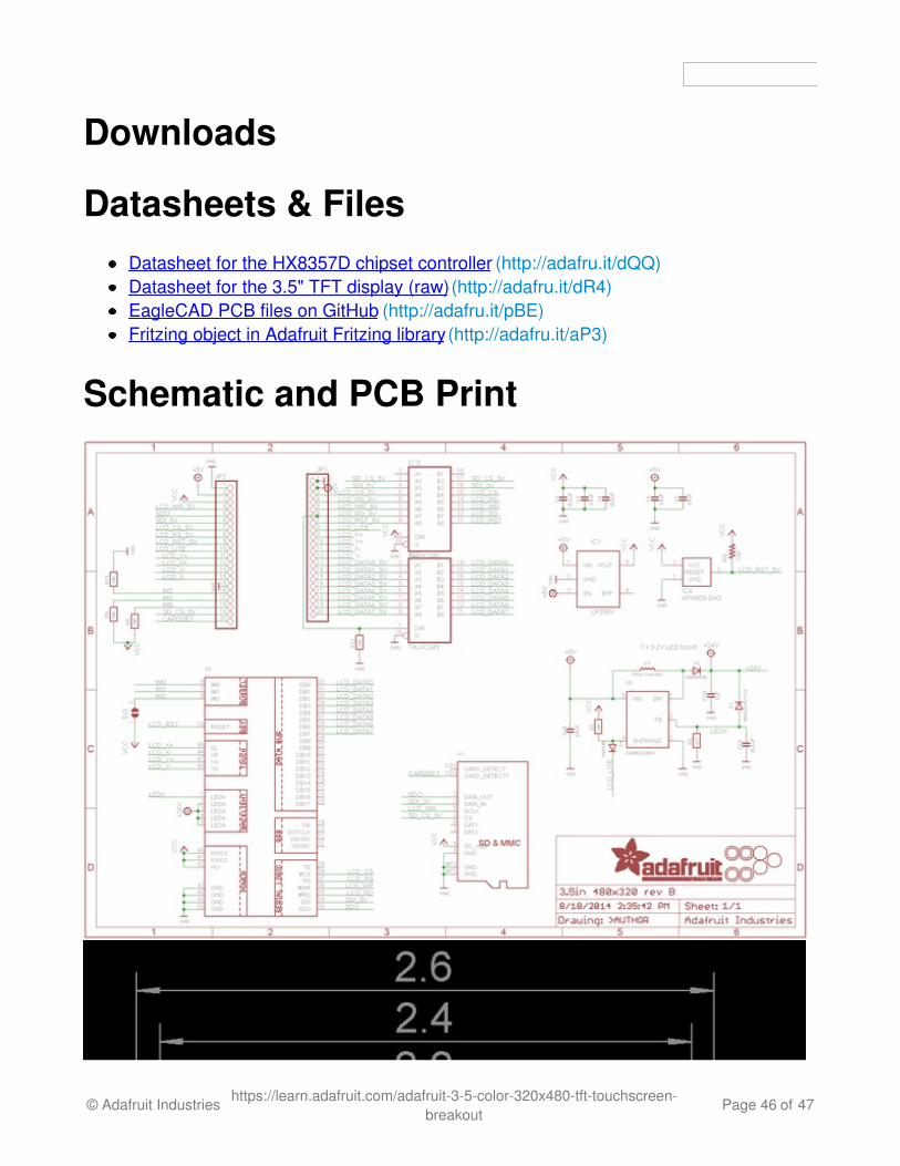
Schematic and PCB Print
© Adafruit Industries https://learn.adafruit.com/adafruit-3-5-color-320x480-tft-touchscreen-breakout
Page 46 of 47

© Adafruit Industries Last Updated: 2017-01-30 01:59:13 AM UTC Page 47 of 47