ad104-r2, ad104-r5
TRANSCRIPT

Operating instructions
Digital Transducer-Electronics
AD104-R2,AD104-R5

Contents Page
Safety notes ..........................................................................................................................................2
1 Intended use................................................................................................................................3
2 Characteristic features ...............................................................................................................3
3 Mechanical construction ............................................................................................................4
4 Electrical construction ...............................................................................................................5
4.1 Function ...............................................................................................................................5
4.2 Signal processing ................................................................................................................6
Electrical connection ...........................................................................................................................8
5.1 Transducer Connection .....................................................................................................10
5.2 Serial Interface RS-232 (only AD104-R2)..........................................................................10
5.3 Serial Interface RS485 (Bus mode with AD104-R5) .........................................................11
6 Command set ............................................................................................................................14
6.1 Command format ...............................................................................................................14
6.2 Answers to commands ......................................................................................................15
6.3 Output types for the measured values...............................................................................15
6.4 Command overview ...........................................................................................................16
7 Individual descriptions of the commands ..............................................................................17
7.1 Interface commands (asynchronous, serial) ......................................................................17
7.2 Adjustment and scaling......................................................................................................27
7.3 Measuring ..........................................................................................................................35
7.4 Special functions................................................................................................................47
7.5 Error messages .................................................................................................................62
7.6 Bus termination for RS-485 version...................................................................................63
7.7 Commands for Legal for trade Applications.......................................................................64
7.8 Further commands.............................................................................................................67
7.9 Examples of communication..............................................................................................68
8 Technical data ...........................................................................................................................72
2 / 75
ba_aed104_8_e.doc
Safety notes
• In the normal case the product causes no dangers, provided the notes and instructions for configuring,installation, operation as intended and maintanance are complied with.
• The safety and accident prevention regulations applicable corresponding to the application must beobserved without fail.
• Installation and commissioning may be performed exclusively by qualified personell.
• Avoid the penetration of dirt and moisture into the interior of the unit when connecting the cables.
• When connecting the cables take measures against electrostatic discharges which can damage theelectronic unit.
• An extra low voltage with safe isolation from the mains is required for the power supply of the unit.
• When connecting additional devices, the safety regulations according to EN610101) must be complied with.
• Shielded cables are required for all connections. The shield must be connected flatly with ground at bothends.
1) "Safety regulations for electrical measuring, control and laboratory equipment”
AD104-R2, AD104-R5 3 / 75
ba_aed104_8_e.doc
1 Intended use
The digital sensor electronic units AD104 belong to the family of AED components which digitally condition andnetwork as bus-capable signals of mechanical measured value transducers. The objective of these componentsis the digitization and conditioning of the measuring signals directly at the transducer. The AD104 and thetransducer (load cell) form a unit and cannot be replaced separately (transducer calibration of the measurementchain with SZA/SFA is necessary).As transducers, calibrated load cells or force transducers ( adjusted in TCZ,TCS, and zero point) can be used.
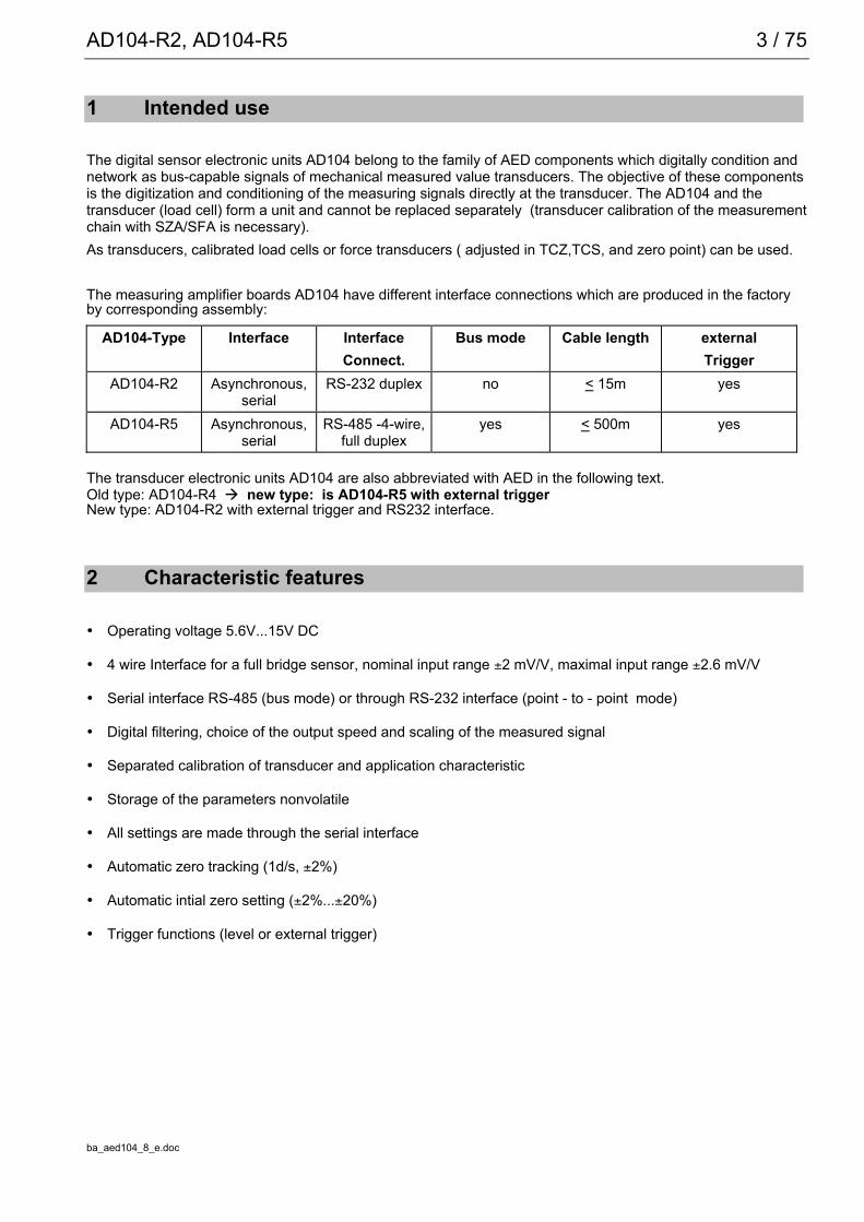
The measuring amplifier boards AD104 have different interface connections which are produced in the factoryby corresponding assembly:
AD104-Type Interface InterfaceConnect.
Bus mode Cable length externalTrigger
AD104-R2 Asynchronous,serial
RS-232 duplex no < 15m yes
AD104-R5 Asynchronous,serial
RS-485 -4-wire,full duplex
yes < 500m yes
The transducer electronic units AD104 are also abbreviated with AED in the following text.Old type: AD104-R4 new type: is AD104-R5 with external triggerNew type: AD104-R2 with external trigger and RS232 interface.
2 Characteristic features
• Operating voltage 5.6V...15V DC
• 4 wire Interface for a full bridge sensor, nominal input range ±2 mV/V, maximal input range ±2.6 mV/V
• Serial interface RS-485 (bus mode) or through RS-232 interface (point - to - point mode)
• Digital filtering, choice of the output speed and scaling of the measured signal
• Separated calibration of transducer and application characteristic
• Storage of the parameters nonvolatile
• All settings are made through the serial interface
• Automatic zero tracking (1d/s, ±2%)
• Automatic intial zero setting (±2%...±20%)
• Trigger functions (level or external trigger)

4 / 75
ba_aed104_8_e.doc
3 Mechanical construction
Fig. 3.1: Example of a mechanical construction of a measuring chain (HBM)The amplifier circuit board has to be placed in a shielded housing (EMC protection). The cable connections hasto be shielded leads.With digital transducers (FIT, C16,...) the AD104 is build in the housing of the load cell. For digital measuringchains the AD104 is included in a separate housing in the cable (degree of protection IP 40).Warning: The AD104 board is not protected against electrostatic discharges. Appropriate safety
precautions must be taken for handling during assembly into the transducer.
AD104
Load Cell
Shield
Pancon connectorfemale
1m...500m (depending on the type)
30 cm

AD104-R2, AD104-R5 5 / 75
ba_aed104_8_e.doc
4 Electrical construction
The circuit of the digital transducer electronic unit consists essentially of the following functional groups:
• Transducer supply
• Amplifier
• Analog-digital converter (A/D)
• Microprocessor unit (µP)
• Parameter memory (EEPROM) protected against power failure
• Serial interface (RS232- 2 wire or RS485)
• Power supply
• Trigger input
4.1 Function
Fig. 4.1: Measuring amplifier board AD104 block circuit diagram
The analog transducer signal is initially amplified, filtered and then converted into a digital value in the analog-digital converter. The digitized measuring signal is processed in the microprocessor. The conditioned signal isthen transmitted to a computer through the serial interface. All parameters can be stored in the EEPROM,protected against power failures.
C om pu te r
V o ltages tab ilize r
T ransduce r
1200 ...38400 baud
E E P R O Msupp lyIden tifica tion .,D ig ita l filte r, M eas .ra te , S ca lingIn te rface se tting
In te r-face
AD
AD 104
µ P
< 60m A
5 .6 ...15V
R S -485 -4 -w ire
R S 232
P ow erun it
E xt. T rigge r

6 / 75
ba_aed104_8_e.doc
The transducer electronic unit is adjusted in the factory to the no-load and the nominal load of the transducer.The electronic unit determines a factory characteristic through the commands SZA and SFA from thesemeasured values and images the measured values following later by means of this characteristic.The following measured values are delivered according to output format (COF):
Output format Input signal Measured valuesat
NOV = 0
Measuredvalues atNOV > 0
Delivery statusNOV=0
Binary 2 characters(Integer)
0...Nominal load 0 ... 20 000 Digit 0 ... NOV
Binary 4 characters(Long Integer)
0...Nominal load 0 ... 5 120 000 Digit 0 ... NOV
ASCII 0...Nominal load 0 ... 1 000 000 Digit 0 ... NOV x
You have the possibility of adapting the characteristic to your requirements (i.e. scale characteristic)correspondingly with the parameter pair LDW and LWT and to standardize the measured values to the requiredscaling value (e.g. 3000d) via the command NOV.
4.2 Signal processing
Measuringbridge
Ampli-fier Filter Factory
scalingMeasur.rate
User scaling,LinearizationZTR, ZSE
Net
ASF ICR
ADC
Netmeasuredvalue
Grossmeasuredvalue
SZASFA
LDWLWT
NOVLIC TAV, TAS
TAR
FMD
Fig. 4.2.1:Signal flow diagramAfter amplification and AD conversion, the signal is filtered by adjustable digital filters (command ASF). Thefactory characteristic is determined with the aid of the commands SZA and SFA.The measuring signal bandwidth (digital filter) is set with the command ASF. The measuring rate (number ofmeasurements per time unit) can be changed depending upon the filter bandwidth with the command ICR.The user can set his own characteristic (commands LDW, LWT, NOV) without changing the factory calibration(SZA/SFA). Furthermore, gross/net switch-over is available (command TAS). Using the command ZSE anautomatic switch-on zero setting can be activated. An automatic zero tracking function (ZTR) is also available.For a linearization of the scale characteristic, the command (LIC) is available (with a polynomial of the 3rdorder). The polynomial parameters can be determined by means of a HBM PC program AED_LIC.The current measured value is retrieved by the command MSV?. The format of the measured value (ASCII orbinary) is set by the command COF. An automatic measured value output can also be selected via thecommand COF.Two types of digital filters, which are switched over using the command FMD, are implemented in the AED. AtFMD0 filters lower than 1 Hz bandwidth are also available. In the filter mode FMD1, filters with fast transientrecovery are activated with high damping in the stop band. You will find detailed information in the chapter‘Individual descriptions of the commands’.
AD104-R2, AD104-R5 7 / 75
ba_aed104_8_e.doc
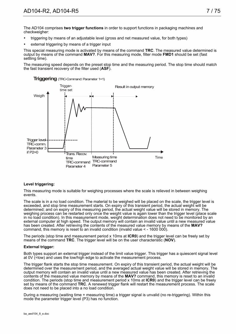
The AD104 comprises two trigger functions in order to support functions in packaging machines andcheckweigher:• triggering by means of an adjustable level (gross and net measured value, for both types)• external triggering by means of a trigger inputThis special measuring mode is activated by means of the command TRC. The measured value determined isoutput by means of the command MAV?. For this measuring mode, filter mode FMD1 should be set (fastsettling time).The measuring speed depends on the preset stop time and the measuring period. The stop time should matchthe fast transient recovery of the filter used (ASF).
Level triggering:This measuring mode is suitable for weighing processes where the scale is relieved in between weighingevents.The scale is in a no load condition. The material to be weighed will be placed on the scale, the trigger level isexceeded, and stop time measurement starts. On expiry of this transient period, the actual weight will bedetermined; and on expiry of this measuring period, the actual weight value will be stored in memory. Theweighing process can be restarted only once the weight value is again lower than the trigger level (place scalein no load condition). In this measurement mode, weight determination does not need to be monitored by anexternal computer at high speed. The output memory will contain an invalid value until a new measured valuehas been created. After retrieving the contents of the measured value memory by means of the MAV?command, this memory is reset to an invalid condition (invalid value < - 1600 000).The periods (stop time and measurement period x 10ms at ICR0) and the trigger level can be freely set bymeans of the command TRC. The trigger level will be on the user characteristic (NOV).External trigger:Both types support an external trigger instead of the limit value trigger. This trigger has a quiescent signal levelat 0V (=low) and uses the low/high edge to activate the measurement process.The trigger flank starts the stop time measurement. On expiry of this transient period, the actual weight will bedetermined over the measurement period, and the averaged actual weight value will be stored in memory. Theoutput memory will contain an invalid value until a new measured value has been created. After retrieving thecontents of the measured value memory by means of the MAV? command, this memory is reset to an invalidcondition. The periods (stop time and measurement period x 10ms at ICR0) and the trigger level can be freelyset by means of the command TRC. A renewed trigger flank will restart the measurement process. The scaledoes not need to be placed into a no load condition.During a measuring (waiting time + measuring time) a trigger signal is unvalid (no re-triggering). Within thismode the parameter trigger level (P3) has no function.
Trans. Recov.timeTRC-commandParameter 4
Measuring timeTRC-commandParameter 5
Weig ht
Time
Triggering (TRC-Command: Parameter 1=1)
Trigger levelTRC-comm.Parameter 3if P2=0
Result in output memory

8 / 75
ba_aed104_8_e.doc
5 Electrical connection
Fig. 5: Connection schema of the PCB and shielding concept of a measuring chainThe connection to the PC is effected by means of a 6 / 8 pin Pancon connector. The following pin wirings resultat the connector according to the set interface (i.e. measuring chains of HBM):
AD104 type AD104-R5 AD104-R2Pancon Connector Signals RS-485 Signals RS-232
1. red UB UB2. white GND GND3. blue TA RxD4. green RA TRG5. black TB TXD6. grey RB GND7. yellow TRG -8. - -
- do not connect!The measuring chain of HBM with AD104-R5 has a 8 wire shielded cable.The measuring chain of HBM with AD104-R2 has a 6 wire shielded cable.Explanation: UB Supply voltage (+ 5.6V...15V)
GND GroundRA 4-wire connection AED receiver, line A (=RX-)RB 4-wire connection AED receiver, line B (=RX+)TA 4-wire connection AED transmitter, line A (=TX-)TB 4-wire connection AED transmitter, line B (=TX+)RxD Receiver data (UART, RS-232)TxD Transmit data (UART, RS-232)TRG External trigger signal
(yellow)

AD104-R2, AD104-R5 9 / 75
ba_aed104_8_e.doc
Trigger input (electrical data):High: 3.2V ... 5VLow: 0V ... 0.8VInput current: <2.5 mA
Important notes on EMC protection:
The PCB AD104 alone has no EMC protection. The EMC protection can be achieved in addition with a shieldedhousing for the electronic and the use of shielded cable.
Mount the load cell onto a metallic carrier which is connected to the ground connection of the device, or shieldAD104 with the load cell and load introduction parts as a complete unit. The cable shield needs to be connectedwith the measuring body of the loadcell and the housing of the AED.
The housing of the AED or the load cell has to be connected via the solder pad to the PCB (see Fig. 5,‘connection to housing’). The AED unit itself is provided with a protective filter for all interfaces and supply lines.
The connection between load cell and electronics should be as short as possible. Depending on the bridgeresistance of the transducer used, line length, and line cross-section of the transducer connection cable, voltagedrops arise that lead to a reduction in the bridge supply voltage. Additionally, the voltage drop on the connectioncable is also temperature-dependent ( copper resistance ). The transducer output signal also changes inproportion to the bridge supply voltage.
With the 4-wire circuit used, there still result measurement errors in conditions with changing temperatures,caused by the temperature-dependent cable resistance and possibly also by transitory resistances in theconnectors.
When setting up a measurement chain (electronics outside the transducer) it should also be noted that theAD104 uses a rectangular carrier frequency for bridge supply. Therefore, the cable length between AD104 andthe transducer is limited to 100 cm max. For high precision applications(>= 3000d), the length should bereduced to 30cm (shielded cable, shield connection on the measuring body and on the shielded housing forAD104).

10 / 75
ba_aed104_8_e.doc
5.1 Transducer Connection
AD104 41-Ub2-GND3456
n.c.UBr2IN4IN1UBr3n.c.
Fig. 5.1: Transducer connection with the PCB (n.c. - not connected)The AED amplifier is allready mounted with the transducer. A changing of the modules (AED or transducer) isonly allowed in HBM factory.For the transducer connection a 4 core shielded cable has to be used.
Connection Pads for a full bridge:
Pad Discription
UBr2 bridge excitation 2
IN4 amplifier input 4
IN1 amplifier input 1
UBr3 bridge excitation 3
Notes on cable length:
The connection between load cell and electronics should be as short as possible. Depending on the bridgeresistance of the transducer used, line length, and line cross-section of the transducer connection cable, voltagedrops arise that lead to a reduction in the bridge supply voltage. Additionally, the voltage drop on the connectioncable is also temperature-dependent ( copper resistance ). The transducer output signal also changes inproportion to the bridge supply voltage.With the 4-wire circuit used, there still result measurement errors in conditions with changing temperatures,caused by the temperature-dependent cable resistance and possibly also by transitory resistances in theconnectors.When setting up a measurement chain (electronics outside the transducer) it should also be noted that theAD104 uses a rectangular carrier frequency for bridge supply. Therefore, the cable length between AD104 andthe transducer is limited to 100 cm max. For high precision applications(>= 3000d), the length should bereduced to 30cm (shielded cable, shield connection on the measuring body and on the shielded housing forAD104).
5.2 Serial Interface RS-232 (only AD104-R2)
The AD104-R2 is a version of the AD104 with an asynchronous, serial interface (UART interface with RS-232line driver). This interface provide a point – to – point communication (no bus mode).The baud rate of 1200...38400 baud can be selected for this interface. The following specifications result for thetransmission of one character:Start bit: 1Number of data bits: 8Parity bit: none / evenStop bit: 1
AD104-R2, AD104-R5 11 / 75
ba_aed104_8_e.doc
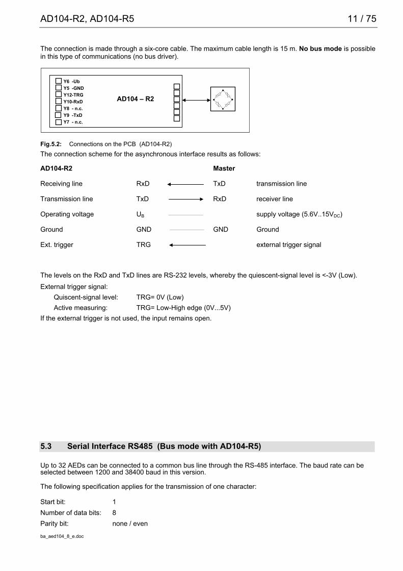
The connection is made through a six-core cable. The maximum cable length is 15 m. No bus mode is possiblein this type of communications (no bus driver).
AD104 – R2
Y6 -UbY5 -GNDY12-TRGY10-RxDY8 - n.c.Y9 -TxDY7 - n.c.
Fig.5.2: Connections on the PCB (AD104-R2)The connection scheme for the asynchronous interface results as follows:
AD104-R2 Master
Receiving line RxD TxD transmission line
Transmission line TxD RxD receiver line
Operating voltage UB supply voltage (5.6V..15VDC)
Ground GND GND Ground
Ext. trigger TRG external trigger signal
The levels on the RxD and TxD lines are RS-232 levels, whereby the quiescent-signal level is <-3V (Low).External trigger signal:
Quiscent-signal level: TRG= 0V (Low)Active measuring: TRG= Low-High edge (0V...5V)
If the external trigger is not used, the input remains open.
5.3 Serial Interface RS485 (Bus mode with AD104-R5)
Up to 32 AEDs can be connected to a common bus line through the RS-485 interface. The baud rate can beselected between 1200 and 38400 baud in this version.
The following specification applies for the transmission of one character:
Start bit: 1Number of data bits: 8Parity bit: none / even

12 / 75
ba_aed104_8_e.doc
Stop bit:^ 1
AD104 – R5
Y6 -UbY5 -GNDY12-TRGY10-TAY8 -RAY9 -TBY7 -RB
Fig. 5.3.1: AD104-R5 for 4-wire bus mode (PCB connections)
1. Long lcable lengths (up to 500m) can be achieved with the aid of the RS485 bus drivers.
2. The bus mode of the AED is designed as master-slave configuration, whereby the AED implements aslave. Thus all activities of the AED are initiated by the control computer. Each AED receives its owncommunication address (00 ... 31) and can be activated through a select command Sii (ii= 00...31). Abroadcast command (S98) is implemented for certain cases of communication. This means that after sucha command, all AED execute the command of the master, but no AED answers. All commands of thiscommunication as well as corresponding examples are described in Chapter 7.
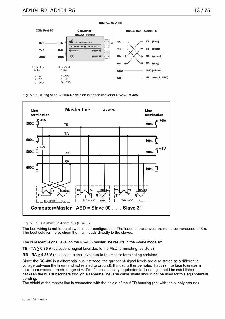
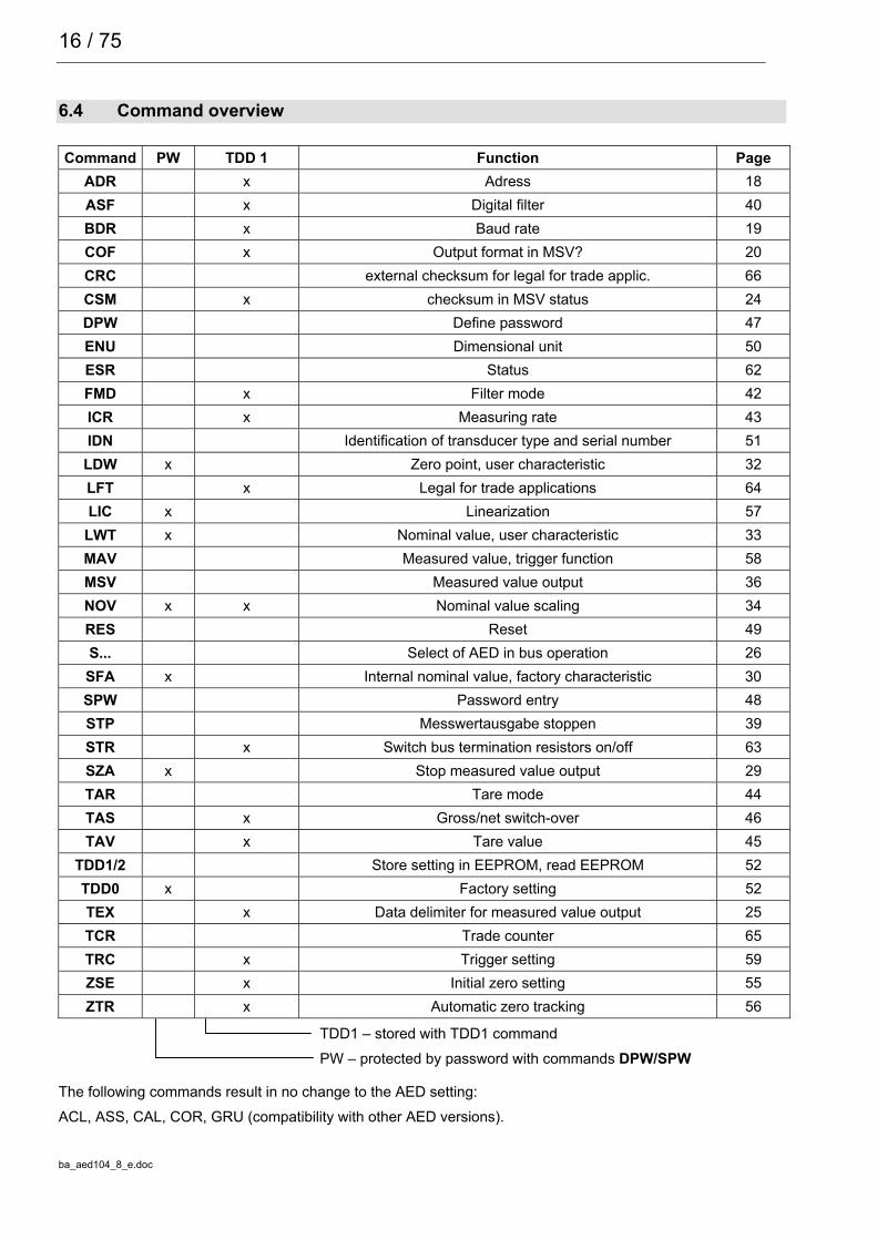
Figure 5.3.2 shows the connection of the bus to the RS232/RS485 Converter(HBM Ordering-No. 1-SC232/422A).Figure 5.3.3 shows the RS485 bus connection.The terminating resistors of 500 ohms drawn in Figure 5.3.3 for the electrical function of the bus system areimportant. These resistors protect the quiescent-signal levels for the receivers on the bus line. The master linemay be terminated with these resistors in this case only at the line ends. The master and the AED with theaddress 31 should contain the terminating resistors for the local distribution of the bus connections shown in theFigure. The AED contains these resistors already. These can be activated by the command STR1 (theseterminating resistors are switched off on factory delivery). These terminations may not be activated more thantwice in one bus.The HBM interface converter also includes these terminators.External trigger signal:
Quiscent-signal level: TRG= 0V (Low)Active measuring: TRG= Low-High edge (0V...5V)
If the external trigger is not used, the input remains open.
AD104-R2, AD104-R5 13 / 75
ba_aed104_8_e.doc
Fig: 5.3.2: Wiring of an AD104-R5 with an interface converter RS232/RS485
RTTB
RxDTxD on/off
TB
TA
+5V500Ω
+5V500Ω
500Ω 500Ω
RB
RA
+5V500Ω
+5V500Ω
500Ω 500Ω
TA RB RA
RTRxDTxD on/off
TB TA RB RA
RTRxDTxD on/off
TB TA RB RA
Master line 4 - wire
Computer=Master AED = Slave 00 Slave 31 . . .
Linetermination
Linetermination
Fig: 5.3.3: Bus structure 4-wire bus (RS485)The bus wiring is not to be allowed in star configuration. The leads of the slaves are not to be increased of 3m.The best solution here: choin the main leads directly to the slaves.
The quiescent -signal level on the RS-485 master line results in the 4-wire mode at:TB - TA > 0.35 V (quiescent -signal level due to the AED terminating resistors)RB - RA > 0.35 V (quiescent -signal level due to the master terminating resistors)Since the RS-485 is a differential bus interface, the quiescent-signal levels are also stated as a differentialvoltage between the lines (and not related to ground). It must further be noted that this interface tolerates amaximum common-mode range of +/-7V. If it is necessary, equipotential bonding should be establishedbetween the bus subscribers through a separate line. The cable shield should not be used for this equipotentialbonding.The shield of the master line is connected with the shield of the AED housing (not with the supply ground).
))
)

14 / 75
ba_aed104_8_e.doc
6 Command set
The commands can be classified roughly into:
• Interface commands (ADR, BDR, Sxx, TEX, COF, CSM)
• Commands for adjusting and scaling (SZA, SFA, LDW, LWT, NOV, LIC)
• Commands for the measuring mode (MSV, ASF, ICR, TAR, TAS, TAV, FMD, STP)
• Special commands (ZSE, ZTR, TDD, RES, DPW, SPW, IDN, STR, TRC, MAV)
• Command for legal for trade applications (LFT, TCR, CRC)
6.1 Command format
General notes:The commands can be input in uppercase or lowercase type.Each command has to be terminated by a termination character. This can be optionally a line feed (LF) or asemicolon (;). If only a termination character is sent to the AED, then the input buffer of the AED is cleared.The statements made in round brackets () in the commands are urgently necessary and must be entered.Parameters in pointed brackets <> are optional and can also be dispensed with. The brackets themselves arenot entered. Text must be included in “ “.With numerical entries, leading zeros are suppressed. Numbers can be entered either directly or in exponentformat, e.g. +12000lf or +1,2e4lf. The exponent e can be one- or two-digit, but a number including sign andexponent must not be more than 10 characters in length.Answers consist of ASCII characters and are terminated with CRLF. The binary character output is anexception (see command MSV).Each command consists of the command initials, the parameter(s) and the termination character.
Command initials Parameters End characterInput ABC X,Y LF or ;
Output ABC? X,Y LF or ;
Example: MSV?2020 measured values are output after this command.All ASCII characters <=- 20H (blank) may stand between command initials, parameters and end character,except for 11H (ctrl q) and 13H (ctrl s).H: Hexadecimal.

AD104-R2, AD104-R5 15 / 75
ba_aed104_8_e.doc
6.2 Answers to commands
Answers to inputs (exception COF64...COF79):
Answer End characterCorrect input 0 (zero) CRLFFaulty input ? CRLF
Exceptions: The commands RES, STP, S00 ... S99 deliver no answer.The command BDR delivers the answer in the new baud rate.
An error flag is received through the command ESR.Answers to output commands:
Correct command Parameter1, ... Parameter n, or measured values CRLFFaulty command ? CRLF (error flag via command ESR )
6.3 Output types for the measured values
You can select two types of output and a data delimiter (command TEX).
Output type 1: The measured values are output arranged beneath one another.
Measured value1 CRLFMeasured value2 CRLF. . . . . . . .Measured value n CRLF
Output type 2:The measured values are output arranged next to one another.Measured value1 (data delimiter) Measured value2 (data delimiter) ... Measured value n CRLF
The measured value query works with fixed output lengths(see command COF):
Format command AED answer Number of bytesCOF0; msv?; yyyy CR LF (y- binary) 6COF2; msv?; yy CR LF (y- binary) 4COF3; msv?; xxxxxxxx CR LF (x- ASCII) 10COF9; msv?; xxxxxxxx,xx,xxx CR LF (x- ASCII) 17
There is always a CRLF or the data delimiter defined by the command TEX as end identification of themeasured value output. However these characters must not be filtered out as end identification in the binaryoutput, since these characters can also be contained in the binary code of the measured value. Therefore onlycounting the bytes helps in the binary output. The corresponding places after CR or LF or the data delimiter canthen be enquired for subsequent syntax testing.Password protection:The password protection of the AED comprises important settings for the characteristic of the scaleand its identification. Commands with password protection are activated only after the password isentered. These commands are answered with “?“ without entry of the password through the commandSPW.
16 / 75
ba_aed104_8_e.doc
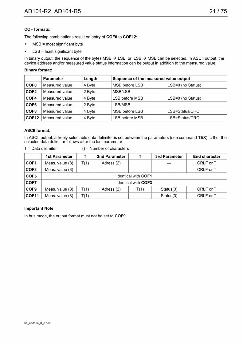
6.4 Command overview
Command PW TDD 1 Function PageADR x Adress 18ASF x Digital filter 40BDR x Baud rate 19COF x Output format in MSV? 20CRC external checksum for legal for trade applic. 66CSM x checksum in MSV status 24DPW Define password 47ENU Dimensional unit 50ESR Status 62FMD x Filter mode 42ICR x Measuring rate 43IDN Identification of transducer type and serial number 51LDW x Zero point, user characteristic 32LFT x Legal for trade applications 64LIC x Linearization 57LWT x Nominal value, user characteristic 33MAV Measured value, trigger function 58MSV Measured value output 36NOV x x Nominal value scaling 34RES Reset 49S... Select of AED in bus operation 26SFA x Internal nominal value, factory characteristic 30SPW Password entry 48STP Messwertausgabe stoppen 39STR x Switch bus termination resistors on/off 63SZA x Stop measured value output 29TAR Tare mode 44TAS x Gross/net switch-over 46TAV x Tare value 45
TDD1/2 Store setting in EEPROM, read EEPROM 52TDD0 x Factory setting 52TEX x Data delimiter for measured value output 25TCR Trade counter 65TRC x Trigger setting 59ZSE x Initial zero setting 55ZTR x Automatic zero tracking 56
TDD1 – stored with TDD1 command PW – protected by password with commands DPW/SPW
The following commands result in no change to the AED setting:ACL, ASS, CAL, COR, GRU (compatibility with other AED versions).

AD104-R2, AD104-R5 17 / 75
ba_aed104_8_e.doc
7 Individual descriptions of the commands
7.1 Interface commands (asynchronous, serial)
Characteristic data of the interfaces
Start bit: 1Word length: 8 bitsParity: none / evenStop bit: 1Software handshake (XON / XOFF) is possibleBaud rate: 1200; 2400; 4800; 9600;19200; 38400 baud
The asynchronous interface of the AED is a serial interface, i.e. the data are transmitted bit for bit after oneanother and asynchronously. Asynchronous means that the transmission works without a clock signal.A start bit is set before each data byte. The bits of the word, a parity bit for the transmission protocol (optional)and a stop bit then follow.
Fig. 7.1.1: Composition of a character
Since the data are transmitted after one another, the transmission speed must agree with the reception speed.The number of bits per second is called baud rate.The exact baud rate of the receiver is synchronized with the start bit for each transmitted character. The databits which all have the same length then follow. After the stop bit is reached, the receiver goes into a ‘waitingposition’ until it is reactivated by the next start bit.The number of characters per measured value depends upon the selected output format (COF command) andcan be 2 to 17 characters (see also COF command).The interface must be configured to build up the communication between AED and computer. The followingcommands are provided in the AED for this : ADR; BDR; COF; TEX; S..;
Start Parity Stop
1 Bit Word length = 8 data bits 1 Bit 1 Bit
1 character

18 / 75
ba_aed104_8_e.doc
ADR Address(device address)
Range: 0...31Factory setting: 31Response time: <15msParameters: 2Password protection: noneParameter protect.: with command TDD1
Input: ADR(new address),<"Serial No.">;Entry of the device address as decimal number 0...31.
The serial number can also be stated optionally as 2nd parameter. The new address is then entered only for theAED with the stated serial number. This makes it possible to change device addresses in the case of severalAEDs with the same address (initialization of the bus mode).The serial number must be stated in “ “ as in the command IDN.
Example: ADR25,"007" CRLF
Query: ADR?; 25CRLF (Example)
Effect: Output of the device address as decimal number 0...31

AD104-R2, AD104-R5 19 / 75
ba_aed104_8_e.doc
BDR Baud Rate(Baud rate)
Baud rates: 1200, 2400, 4800, 9600, 19200, 38400 BaudFactory setting: 9600 Baud and even parityResponse time: <15msParameters: 1Password protection: noneParameter protect.: with command TDD1
Input: BDR <Baudrate>,<Parity>Entry of the required baud rate as decimal number.
Possible baud rates are:1200, 2400, 4800, 9600, 19200, 38400 BaudInput or the requested parity:0= without parity bit1= with even parity bit
Important Note
The answer is given in the new setting (baud rate, parity). Communication is no longer possible initially after achanged baud rate. The computer must also be changed over to the newly selected baud rate setting.So thatthe baud rate remains changed permanently, it must be stored in the EEPROM with the command TDD1. Thisprocedure serves also as safeguard that no baud rates can be set in the AED which the remote station does notsupport. If the newly entered baud rate is not stored, the AED reports after a reset or power On again in thepreviously valid baud rate.
Query: BDR?;
Effect: Output of the set baud rate, Identification for parity bit
Example: BDR?; 9600,1 CRLF corresponds to 9600 baud, even parity

20 / 75
ba_aed104_8_e.doc
COF Configurate Output Format(Ausgabeformat für die Messwertausgabe)
Range: 0...255Factory setting: 9Response time: <15msParameters: 1Password protection: noneParameter protect.: with command TDD1
Input: COF(0...255);Input of the output format for measured value command MSVThe possible formats and the decimal number to be entered for them are listed in the following Table. Themeasured value output refers here to the set nominal value of the AED (see command NOV).
Output at max. capacity NOV> 0 NOV= 02 Byte binary NOV value 200004 Byte binary NOV value 5120000ASCII NOV value 1000000
For the 2-bytes binary output, the NOV value must be < 30000, otherwise the measured value is output withoverflow or underflow (7fff H or 8000H). With NOV30000, the overload range is only still approx. 2700 digits.Query: COF?;
Effect: Output of the selected output format as three-digit decimal number from 0...255
AD104-R2, AD104-R5 21 / 75
ba_aed104_8_e.doc
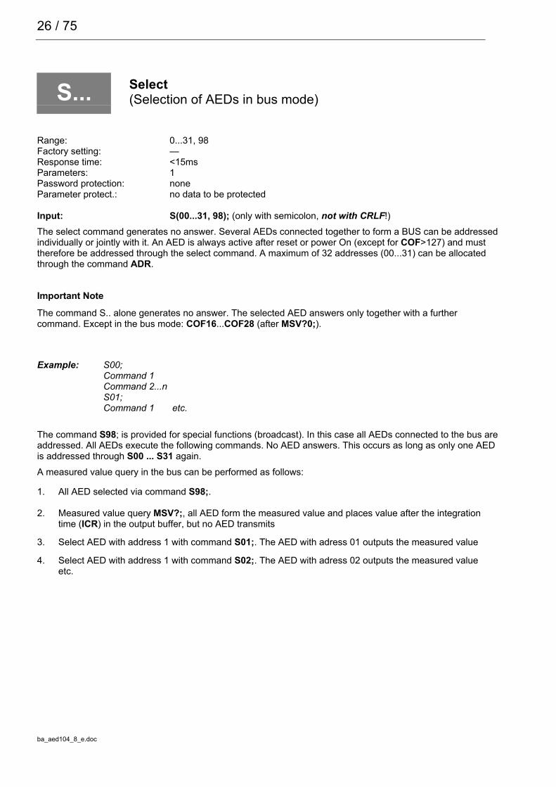
COF formats:
The following combinations result on entry of COF0 to COF12:
• MSB = most significant byte
• LSB = least significant byteIn binary output, the sequence of the bytes MSB LSB or LSB MSB can be selected. In ASCII output, thedevice address and/or measured value status information can be output in addition to the measured value.Binary format:
Parameter Length Sequence of the measured value outputCOF0 Measured value 4 Byte MSB before LSB LSB=0 (no Status)COF2 Measured value 2 Byte MSB/LSBCOF4 Measured value 4 Byte LSB before MSB LSB=0 (no Status)COF6 Measured value 2 Byte LSB/MSBCOF8 Measured value 4 Byte MSB before LSB LSB=Status/CRCCOF12 Measured value 4 Byte LSB before MSB LSB=Status/CRC
ASCII format:In ASCII output, a freely selectable data delimiter is set between the parameters (see command TEX). crlf or theselected data delimiter follows after the last parameter.T = Data delimiter () = Number of characters
1st Parameter T 2nd Parameter T 3rd Parameter End characterCOF1 Meas. value (8) T(1) Adress (2) — CRLF or TCOF3 Meas. value (8) — — CRLF or TCOF5 identical with COF1COF7 identical with COF3COF9 Meas. value (8) T(1) Adress (2) T(1) Status(3) CRLF or TCOF11 Meas. value (8) T(1) — — Status(3) CRLF or T
Important Note
In bus mode, the output format must not be set to COF9.

22 / 75
ba_aed104_8_e.doc
Bus mode: COF16 to COF 28
If the decimal number 16 is added to the above stated output formats COF0...COF12, then the AED is switchedinto the bus output mode. A measured value is output. The AED switches over to the partially active mode (eachnew measured value is stored in the output buffer but not output). The measured value is output on the bus withthe select command S..;.
Example: 2 AED’s in bus operation
Command EffectS98; All AED are partially active (listening but not transmission)COF18; Output in 2 byte binary outputICR0; Maximum measuring rateMSV?0; Continuous measurement in AEDS01; Read measured value from 1st AED, immediate output of current measured value, without
measuring timeS02; Read measured value from 2nd AED, when response from first AED has been received
completely. Immediate output of current measured value, without measuring time
S01; Read measured value from 1st AED, when response from second AED has been receivedcompletely
S02; Read measured value from 1st AED, when response from second AED has been receivedcompletely
... ...STP; Stop measured value outputS01; Poss. new setting for 1st AED
Binary measured value output without CRLF: COF32 to COF44
If the decimal number 32 is added to the above stated binary output formats COF0...COF12, the AED isswitched into the following output mode for the measured values.In the binary measured value output, the end character CR LF is left out, so that only 2 or 4 characters permeasured value are output. This measure increases the output speed of the measured values.
Format Length Sequence of the measured value outputCOF32 4 Byte MSB before LSB LSB=0 (no status)COF34 2 Byte MSB before LSBCOF36 4 Byte LSB before MSB LSB=0 (no status)COF38 2 Byte LSB before MSBCOF40 4 Byte MSB before LSB LSB=status/CRCCOF44 4 Byte LSB before MSB LSB=status/CRC
2-wire bus mode: COF64 ... COF76 (do not use for variants AD104-R2 and AD104-R5)If the decimal number 64 is added to the above stated output formats COF0...COF12, then the AED is switchedinto the 2-wire bus mode. This means that the AED answers no longer with “0“ or “?“ on command inputs. Theanswer with the parameter or in the case of MSV? with the measured value occurs only for command enquiries(e.g. ASF?). The command MSV?0; (continuous measured value transmission) may no longer be used in thiscase since otherwise it is no longer possible to stop this output (apart from supply voltage off).

AD104-R2, AD104-R5 23 / 75
ba_aed104_8_e.doc
Continuous output after power On: COF128 to COF 140If the decimal number 128 is added to the above stated output formats COF0...COF12, then the AED isswitched into the continuous output mode. After the power On or RES command, the AED outputs themeasured values without MSV? request. The continuous output can be switched off with the command STP.
The setting is made with the following entries (COF≥128):
1. ... make necessary settings
2. ICRi; set measuring rate of the AED
3. COFx+128; the AED transmits measured values continuously,time interval corresponding to ICR, x=0...12
4. STP; stop continuous transmission
5. TDD1; store protected against power failure
6. COFx+128; the AED transmits measured values continuously, time interval corresponding to ICR.
The AED starts with the measured value output without separate request also after switching on the voltage.
These output formats have another special feature (depending on how triggering is set, command TRC):Trigger deactivated: continuous automatic measured value outputTrigger activated: automatic measured value output only if a new measured value has been
created after triggering (MAV? output value).Output speed of measured values:The AD104 can output a maximum of 100 measured values per second. This data rate also depends upon thebaud rate (BDR), the data format of the measured value output and the set averaging (ICR).Table 1 shows this relationship in the continuous measured value output (MSV?0):
Measured values/s 100 50 25 12 6 3 2 1(ICR)Time in ms 10 20 40 80 160 330 500 1000Output format (COF) necessary baud rates for MSV0; (BDR)Binary format2 characters at COF2/COF6
2400 1200 1200 1200 1200 1200 1200 1200
Binary format4 characters at COF0/COF4
4800 2400 1200 1200 1200 1200 1200 1200
ASCII formatMeas. value 10 characters at COF3
19200 9600 4800 2400 1200 1200 1200 1200
ASCII formatMeas. value + Adress13 characters at COF1
19200 9600 4800 2400 1200 1200 1200 1200
ASCII formatMeas. value + Adress + status17 characters at COF9
38400 19200 9600 4800 2400 1200 1200 1200
Note for the evaluation of the binary measured values:The binary codes for CR and LF can occur inside the bytes representing the measured value in the measuredvalue output in binary format. Therefore the contents of the measured value output must not be tested for thecharacters CR/LF in order possibly to check the end of the measured value transmission. Rather the number ofcharacters which are received should be registered for the binary output. The control characters CR/LF are alsoappended to the measured value in the binary output (sole exception: MSV?0;).

24 / 75
ba_aed104_8_e.doc
CSM Checksum(Cheksum only in MSV binary status)
Range: 0/1Factory setting: 0Response time: <15msParameters: 1Password protection: noneParameter protect.: with command TDD1
Input: CSM(0/1);
Query: CSM?;
Effect: The adjusted fuction is given out as: (0/1).The command checksum can be used to find out transmitting errors within 4 Byte binary output.If CSM=0 the normal status will be transmitted (see MSV).If CSM=1 in stead of the status a checksum will be transmitted in the binary output format COF8 and COF12(+i∗16, i=0,1...7). The checksum is a EXOR over the 3 bytes of the measured value.

AD104-R2, AD104-R5 25 / 75
ba_aed104_8_e.doc
TEX Terminator Execution(Data delimiter between measured values)
Range: 0...255Factory setting: 172Response time: <15msParameters: 1Password protection: noneParameter protect.: with command TDD1
Input: TEX(0...255);The wanted data delimiter is input in decimal form as ASCII character (e.g. comma = 2CH = 44 D inputTEX44; H: Hexadecimal, D: Decimal). Any ASCII character from 0...127D (0...7FH) can be taken as datadelimiter. The data delimiter is set between the parameters in the measured value output (see also commandsMSV and COF).
Example: TEX44;Measuring value output: -0123456, 12, 000, -0123457, 12, 000, etc. (at COF9)If the selected ASCII character is entered with an offset of 128(above example: comma = 44 D + 128 D = 172 D entry TEX172;),then the parameters of a measured value are separated by comma as before, but crlf is output at the end of themeasured value.Example: TEX172;This results in: -123456,12,000
-123457,12,000 etc.
Query: TEX?;Effect: The set data delimiter is output as 3-digit decimal number (0...255).
26 / 75
ba_aed104_8_e.doc
S... Select(Selection of AEDs in bus mode)
Range: 0...31, 98Factory setting: —Response time: <15msParameters: 1Password protection: noneParameter protect.: no data to be protected
Input: S(00...31, 98); (only with semicolon, not with CRLF!)The select command generates no answer. Several AEDs connected together to form a BUS can be addressedindividually or jointly with it. An AED is always active after reset or power On (except for COF>127) and musttherefore be addressed through the select command. A maximum of 32 addresses (00...31) can be allocatedthrough the command ADR.
Important Note
The command S.. alone generates no answer. The selected AED answers only together with a furthercommand. Except in the bus mode: COF16...COF28 (after MSV?0;).
Example: S00;Command 1Command 2...nS01;Command 1 etc.
The command S98; is provided for special functions (broadcast). In this case all AEDs connected to the bus areaddressed. All AEDs execute the following commands. No AED answers. This occurs as long as only one AEDis addressed through S00 ... S31 again.A measured value query in the bus can be performed as follows:
1. All AED selected via command S98;.
2. Measured value query MSV?;, all AED form the measured value and places value after the integrationtime (ICR) in the output buffer, but no AED transmits
3. Select AED with address 1 with command S01;. The AED with adress 01 outputs the measured value
4. Select AED with address 1 with command S02;. The AED with adress 02 outputs the measured valueetc.

AD104-R2, AD104-R5 27 / 75
ba_aed104_8_e.doc
7.2 Adjustment and scaling
The commands described below serve for setting the factory characteristic as well as the user characteristic:
• Commands for adjusting the transducer characteristic: SZA, SFA• Commands for adjusting the user characteristic: LDW, LWT• Scaling of the measured values: NOV
Setting the characteristic
As delivered, the AED works initially with a factory characteristic SZA / SFA (range 0...2 mV/V). Thischaracteristic can be used for calibrating the the transducer characteristic. This characteristic should not bechanged. It has to be print ore stored to keep the data.The user can adapt the AED characteristic to his requirements with the command pair LDW, LWT(application or scale characteristic).In the following, the balance of a measuring chain will be described with the balancing of a scale. This examplecan also be used for other kinds of transducers.
Important Note
The characteristic commands LDW, LWT must be entered or executed in the sequence LDW , then LWT... Theinput data are not computed until both parameters have been entered or measured in pairs The scaling must beswitched off when determining the characteristic (NOV0).After the values for zeropoint and nominal value of the user characteristic have been measured or entered, therange LDW LWT (at NOV=0) is mapped to the following numerical ranges:
Output at nom. load (COF) NOV=0 NOV>02 Byte binary 20000 NOV value4 Byte binary 5120000 NOV valueASCII 1000000 NOV value
For the 2-bytes binary output, the NOV value must be < 30000, otherwise the measured value is output withoverflow or underflow (7fff H or 8000H ; H: Hexadecimal). With NOV30000, the overload range is only approx.2700 digits.

28 / 75
ba_aed104_8_e.doc
Set user characteristic with LDW, LWT
Command string
SPW"AED";
LDW;
LWT;
Action
Enter password
Load = 0, scale
Load = Nominal value, scale
Loadin mV
COF31.000.000
User characteristicDigit
0,2
I
II
1,4
Application measuring range
Loadin mV
Factory characteristic1.000.000
Digit
COF3
0,2 21,4
700.000
100.000I
II
Application measuring range
Fig. 7.7-1: Setting the user characteristic

AD104-R2, AD104-R5 29 / 75
ba_aed104_8_e.doc
SZA Sensor Zero Adjust(Factory characteristic – zero point)
Range: 0...1,599999e6Factory setting: adjusted on unloaded transducerResponse time: <15ms...4.2sParameters: 1Password protection: yesParameter protect.: after input of SFA
Input: SZA; (Response time: <4.2s)
Effect: Using this command, the transducer electronic system measures an input signalbetween ±2.5mV/V, stores the measured value as the zero point of the factorycharacteristic, but only starts the calculation of the new characteristic afterentering the parameter for SFA.
Input: SZA<zero value>; (Response time: <15ms)
Effect: Instead of causing the AED to measure the applied signal, the value is enteredhere. The entered value is stored, but accounted for only after entry of theparameter for SFA as the zero point of the factory characteristic.
Query: SZA?; (Response time <15ms)
Effect: The value used in the AED for calculating the factory characteristic for the zeropoint is output in ±7 digits (e.g. -0000345crlf).
Important Note
Entry the command SZA and SFA ore execute. The data will be calculated if both parameters were given inpairs ore been measured.
30 / 75
ba_aed104_8_e.doc
SFA Sensor Fullscale Adjust(Factory characteristic – fullscale value)
Range: 0...1,599999e6Factory setting: adjusted to nominal load of transducerResponse time: <15ms...4.2sParameters: 1 (0)Password protection: yesData protect.: with input
Input: SFA; (Response time: <4,2s)
Effect: Using this command, the transducer electronic system measures an input signalbetween ±2.5mV/V, stores the measured value as the fullscale value of thefactory characteristic and calculates the new characteristic together with thepreviously entered value for SZA.
Input: SFA <fullscale value>; (Response time: <15ms)
Effect: Instead of causing the AED to measure the applied signal, here the value isentered directly as the fullscale value of the factory characteristic, stored andused together with the previously entered value for SZA.
Query: SFA?; (Response time <15ms)
Effect: The value used in the AED for calculating the factory characteristic for the zeropoint is output in ±7 digits (e.g. -0915345CRLF).
Important NoteEntry the command SZA and SFA ore execute. The data will be calculated if both parameters were given inpairs ore been measured.Procedure for entering the factory characteristic:
1. Enter password by means of command SPW
2. Switch off the scaling withNOV 0; output (scaling off)
3. Deactivate user characteristic by means of LDW0; and LWT1000000;
4. Adjust the ASF filter such that a maximally quiescent display is effected
5. Transducer (not scale) without load, wait until standstill
6. Determine measured value with MSV?; , note value1 for SZA7. Load transducer (not scale) with nominal load, wait until standstill
8. Determine measured value with MSV?; , note value2 for SFA
9. Enter new characteristic with : SZA value1; subsequently SFA value2
10. Redetermine the user characteristic LDW/LWT
The points 3...8 are not applicable if the factory characteristic is entered anew using already known parameters.

AD104-R2, AD104-R5 31 / 75
ba_aed104_8_e.doc
User settings:
The commands LDW and LWT work like the commands SZA and SFA . It is possible with these commands tomake a system-specific calibration (e.g. of a scale), without changing the transducer settings performed withSZA and SFA.The user-specific settings LDW/LWT result as an ASCII output within the range 0... 1000000. This characteristicis converted into the NOV by means of the parametersExample: NOV 0; User setting 0...1000000 (ASCII signal
with 0 = unloaded scale, 1000000 at nominal load
NOV 4000; User setting 0...4000With output 0 at load =0 or 4000 at nominal load
Attention:
In an adjustment with SZA and SFA, the parameters for LDW and LWT are reset (default: LDW=0 andLWT=1000000) .There is the option to determine the characteristic with SZA and SFA at any time by enteringLDW0 and LWT1000000. Before setting your new characteristic, enter LDW0,LWT1e6, and NOV0.

32 / 75
ba_aed104_8_e.doc
LDW Load Cell Dead Weight(Zero point of the user characteristic)
Range: 0...1.599999e6Factory setting: 0Response time: <15ms...4.2sParameters: 1Password protection: yesParameter protect.: after input of LWT
Take the zero point of user characteristic with LDWInput: LDW; (Response time: <4.2s)
1. The scale is unloaded.Take the zero point with LDW; command.Using this command, the transducer electronic system measures an input signal between ±2.5mV/V ( i.e.=measured value for scale in no load condition), stores the measured value, but only starts the calculationof the new user characteristic after entering the parameter for LWT.
Individual input of the zero point of the user characteristic via LDWInput: LDW<Zero point> (Response time: <15ms)
1. Insert the value for the zero point of the scale via LDW<Zero point> command. The entered value isstored, but accounted for only after entry of the parameter for LWT.
Query: LDW?; (Response time<15ms)
Effect: Output in ±7 digits (e.g. -0915345crlf) of the zero point value. The value is not converted viaNOV.

AD104-R2, AD104-R5 33 / 75
ba_aed104_8_e.doc
LWT Load Cell Weight(nominal value of the user characteristic)
Range: 0...1,599999e6Factory setting: 1000000Response time: <15ms...4.2sParameters: 1 (0)Password protection: yesParameter protect.: with input
Take the full scale value of user characteristic with LWT commandInput: LWT; (Response time <4,2s):
Using this command, the transducer electronic system measures an input signalbetween ±2.5mV/V ( i.e.= measured value at scale nominal load), stores thismeasured value as the nominal value and calculates the new user characteristictogether with the previously entered value for LDW. The values for SZA andSFA are not changed.
Individual input of the full scale value of the user characteristic via LWT:Input: LWT<Nominal value>; (Reaktionszeit<1,5s):
Instead of causing the AED to measure the applied signal, the value for the end value of theuser characteristic is entered here directly and, in combination with the previously enteredvalue for LWT, used in calculating the user characteristic.
Query: LWT?; (Response time <15ms)
Effect: Output the the value for the user characteristic in ±7 digits (e.g. -0000345CRLF) of thenominal value or the loaded transducer (nominal load). The value is not converted via NOV.
Important NoteAn input or measurement of the factory characteristic with SZA/SFA resets the user characteristic to the defaultvalues LDW=0, LWT=1000000.
Procedure for entering the user characteristic:
1. Enter password by means of command SPW.2. NOV 0; output (scaling off).
3. Adjust the ASF filter such that a maximally quiescent display is effected
4. Scale at no load , wait for standstill
34 / 75
ba_aed104_8_e.doc
5.
NOV Nominal Value(Resolution of the user characteristic)
Range: 0...1,599999e6Factory setting: 0 (=deactivated)Response time: <15msParameters: 1Password protection: yesParameter protect.: with command TDD1
Input: NOV<Wert>;
Query: NOV?; (Response time <15ms)
Effect: The value stored in the AED is output with 7 digits complete with sign ( e.g.0001000CRLF 0000345crlf ).
The NOV value is used for scaling the measured value. At NOV=0 this output scaling is deactivated. The ASCIImeasured value output is scaled to 1000000 at the factory. If a measured value output of 2000 digit at nominalload is required, then use this command to set the nominal value NOV2000. The input parameters or taravalues are not changed by this scaling.
Measured value output format at nominalload
NOV=0 NOV>0
2 Byte binary 20000 NOV value4 Byte binary 5120000 NOV valueASCII 1000000 NOV value
With the 2 byte binary type of output, the NOV value must be < 30000. Otherwise the measured value will beoutput complete with overflow or underflow ( 7fffH or 8000H ; H: Hexadecimal). With NOV30000, the overloadrange is only approx. 2700 digits.
AD104-R2, AD104-R5 35 / 75
ba_aed104_8_e.doc
7.3 Measuring
All commands acting directly on a measured value belong to measuring, these are:
• MSV Measured value output• STP Stop measured value output• ASF Filter setting• FMD Filter mode• ICR Measuring rate• TAR Tare mode• TAV Set tare memory• TAS Gross/net switch-over

36 / 75
ba_aed104_8_e.doc
MSV Measured Signal Value(Output measured values)
Range: Integer ±32767Long Integer ±8388607ASCII ±1000000
Factory setting: ASCIIResponse time: < 2ICR ∗ 10ms + 5ms
with ICR = Measuring rateParameters: 1Password protection: noneParameter protect.: Output measured values
Query: MSV?(0); (not to be used in 2-wire connection)
Effect: Outputs measured values constantly until the output is stopped with thecommand STP
Query: MSV?(1...65535);
Effect: Outputs the stated number of measured values.
(The measured values are output without the control character CR/LF, CR/LF is appended only to the lastoutput measured value).
The measured value is output in ASCII or binary format (see command COF).

AD104-R2, AD104-R5 37 / 75
ba_aed104_8_e.doc
The output format for the measured value must be set previously via the command COF.The measured value is output related to the relevant measuring range. The measured value can be a gross ornet measured value (command TAS). This COF command generates answers of constant length.
The output length for the command MSV?; depends in this case upon the output format (see COF command):
Output format AED answer No. of charactersBinary 4 Byte yyyy CRLF (y – binär) 6Binary 2 Byte yy CRLF (y – binär) 4ASCII (COF3;) xxxxxxxx CRLF (x - ASCII) 10ASCII (COF9;) xxxxxxxx,xx,xxx CR LF (x - ASCII) 17
CR: Carriage Return, LF: Line Feed
-1001500,25,000,
Meas. value status optional
2 Byte adress (00...31) optional
8 Byte measuring value (pos. sign = Blank)
Delimiter can be set (command TEX)Selected delimiter
Example: Definition of a measuring value in ASCII format (COF9)

38 / 75
ba_aed104_8_e.doc
The output scaling depends upon the parameter of the command NOV.
Output format of the measuring value atnominal load
NOV=0 NOV>0
2 Byte binary 20000 NOV value4 Byte binary 5120000 NOV valueASCII 1000000 NOV value
With the 2-byte binary output, the NOV value must be < 30000, otherwise the measured value is output withoverflow or underflow ( 7fffH or 8000H ; H: Hexadecimal). With NOV30000, the overdriving reserve is only stillapprox. 2700 digits.
The response time for the measured value query is determined by the integration time (command ICR):
Filter settings with FMD0 (Querry: MSV?;)
ICR Output rate Mv/s Response time [ms], approx. with MSV?;0 100 101 50 202 25 403 12 804 6 1655 3 3336 2 5007 1 1000
A predefined number P1 of measured values can be output via a command MSV?P1;. The reaction time liesbetween the output of two measured values. The end identification (CR LF) is output only for the last measuredvalue. The total time for the acquisition of P1 measured values is calculated as:
Measuring time [ms] = P1 ∗ 2ICR ∗ 10ms + 5ms,with ICR = Measuring rateThere is a continuous output of measured values with MSV?0;. This output can be stopped only through thecommands STP, RES or voltage switch-off. No other parameters can be changed during the continuous output.In the 4-byte binary output or in the ASCII output, the measured value status can be transmitted with themeasured value (see commands COF).
Error messages in the measured value status
Contents of the status byte inthe measured value output
Possible cause
Bit 0 = 1, Nett-Overflow Tare value too largeBit 1 = 1, Gross-Overflow Scaling too sensitiveBit 2 = 1, ADU-Overflow ADU overdrives (input >± 2.5mV/V)Bit 3 1= Standstill Measuring values are in the range of still standing (±1d/s).Bit 7, 6 = Measured values not coherent Do not fit together. Measured values cannot be output
justified in the selected configuration

AD104-R2, AD104-R5 39 / 75
ba_aed104_8_e.doc
STP Stop(Stop of the measured value output)
The measured value output is ended with this command. STP acts only on the command MSV.A started measured value is output completely.

40 / 75
ba_aed104_8_e.doc
ASF Amplifier Signal Filter(Digital filter setting)
Range: 0...8Factory setting: 5Response time: <15msParameters: 1Password protection: noneParameter protect.: with command TDD1
Input: ASF(0...8);
Query: ASF?;
Effect: Entry of the filter stage as decimal number from (0...8)
The AED has a multi-stage filter chain:
• An analog 3rd order filter (cut-off frequency approx. 50 Hz)
• Averaging over 2 measured values (at 200 Hz scan rate, fixed setting)
• Standard filter (FMD0) or a FIR filter (FMD=1); cut-off frequency selectable through ASF, fixed scan rate =100 Hz
• Averaging for output rate reduction (selectable through ICR, scan rate <=100 Hz)Thus the wanted filter effect and output rate can be set through the two commands (ASF, ICR). Further newefficient digital filters have been implemented apart from the standard filter properties. The command FMD isused for switching over between the two filter modes:
FMD 0; Standard filter
FMD 1; FIR filter (with fast settling time)
Filter characteristics of standard filters (FMD0):
ASF Settling timein ms to 0.1%
Cut-off frequency [Hz]at –3dB
max. attenuation [dB]at 300Hz
1 130 8 -202 320 3,5 -343 700 1,5 -484 1400 0,7 -605 2900 0,3 -726 5800 0,2 -827 11800 0,1 -908 23800 0,05 -96
The filter is switched off at ASF0. The cut-off frequency of the filter determines the settling time. The higher thefilter index, the better is the filter effect but the longer is the settling time on changing the weight. The filtersetting should be chosen as small as possible, whereby the measured value quiescence (standstill) must beguaranteed at unchanging weight.

AD104-R2, AD104-R5 41 / 75
ba_aed104_8_e.doc
The FIR-Filter (FMD1) can be described with the following Table:
ASF Filterlength(Tabs)
Cut-offfrequency [Hz]
at -3dB
20dBattenuation atfrequency in
Hz
40dBattenuation atfrequency in
Hz
Attenuation inthe Stop band
[dB]
Stop band[Hz]
1 12 7.6 17 23 50...100 >252 14 6.6 15 19 50...80 >203 16 6.2 14 17 50...90 >194 16 5.5 12.5 16 50...80 >17.55 18 4.7 11 14 45...80 >156 20 4 9.5 12 45...85 >12.57 22 3.5 8 10 40...85 >108 22 3 7 8 40...80 >8
The filter is switched off with ASF0.The filters ASF6...ASF8 are limited additionally in bandwidth by averaging (ICR>4).The transient recovery time of the filters is calculated from filter length (12...24) multiplied by the filter scan rateof 10ms. Settling time filter : 120ms ... 240ms
Mean value formation (ICR) does affect the total settling time of the measuring chain. The total settling timedepends additionally upon the mechanical construction of the transducer, the dead load of the scale and theweight to be weighed.

42 / 75
ba_aed104_8_e.doc
FMD Filter Mode(Filter selection for the command ASF)
Range: 0/1Factory setting: 0Response time: <15msParameters: 1Password protection: noneParameter protect.: with command TDD1
Input: FMD(0/1);
Entry of the filter stage as decimal number of 0 or 1:
Query: FMD?;
Effect: Output of the set filter stage (0 or 1)
The description of the filter selection can be found in the ASF command description.

AD104-R2, AD104-R5 43 / 75
ba_aed104_8_e.doc
ICR Internal Conversion Rate(Output rate of measured values)
Range: 0...7Factory setting: 0Response time: <10msParameters: 1Password protection: noneParameter protect.: with command TDD1
Input: ICR(0...7);Entry of the measuring rate as decimal number from 0...7
The integration time determines the output data rate of the measured values and thus also the response time tothe measured value query with the command MSV?;. ICRx = Averaging over 2x measuring values , with x= 0...7The following setting possibilities result from this:
ICR Output rate Mv/s0 1001 502 253 124 65 36 27 1
Observe the baud rate setting when setting the measured value rate. A high baud rate must be set at highmeasured value rates to avoid measured data losses (see command COF).Query: ICR?;
Effect: Output of the set measuring rate (0...7)
Important NoteAt ICR1 there is an especially good suppression of a 50 Hz mains frequency which may possibly causeinterference.

44 / 75
ba_aed104_8_e.doc
TAR Tare(Tare modus)
Range: —Factory setting: —Response time: < 2ICR ∗ 10ms + 5 msParameters: 0Password protection: noneParameter protect.: no data to be protected
The current measured value is tared with the command TAR. After taring, the system switches over to "Netmeasured value" (TAS0). The current value is filed in the tare memory (see also command TAV) and subtractedfrom the measured value and all following measured values.

AD104-R2, AD104-R5 45 / 75
ba_aed104_8_e.doc
TAV Tare Value(Set / read tare memory)
Range: 0...±8388607Factory setting: 0Response time: <20msParameters: 1Password protection: noneParameter protect.: with command TDD1
Input: TAV(±Tare value);Enter tare value 7digit with sign (max. ±8 388 607).This value is set off with the LDW/LWT characteristicscaled with the parameter NOV (0...NOV). The tarememory is cleared (contents = 0) after characteristicentries with the commands SZA, SFA or LDW, LWT.
Query: TAV?;Effect: The contents of the tare memory are output.
The tare value is converted to the NOV value.
Output formatmeasured valueat nominal load
Nominaltaring range at
NOV>0
Maximumtaring range at
NOV>0
Nominaltaring range at
NOV=0
Maximumtaring range at
NOV=02 Byte binary ±NOV value ±150% NOV value ±1000000 ±8 388 6074 Byte binary ±NOV value ±150% NOV value ±1000000 ±8 388 607
ASCII ±NOV value ±150% NOV value ±1000000 ±1 599 999
Example:NOV3000; (Scaling the scale)TAS1; (Gross output switched on)MSV?; 1500CRLF (Measured value lies at 50% = nominal load of the scale)TAR; (Taring and switching over to net output)TAV?; 1500CRLF (Enquire tare value)MSV?; 0CRLF (Net measured valuet)TAS?; 0CRLF (Net is switched on)TAS1; 0CRLF (Switching over to gross)MSV?; 3000CRLF (Measured value is at 100% = nominal load of the scale)TAV?; 1500CRLF (Enquire tare value, unchanged)
46 / 75
ba_aed104_8_e.doc
TAS Tare Set(Gross/net switch-over)
Range: 0...1Factory setting: 1 (Gross)Response time: <10msParameters: 1Password protection: noneParameter protect.: with command TDD1
Input: TAS(0...1);
TAS0: Net measured valueThe value in the tare memory is subtracted from the current measured value.
TAS1: Gross measured valueThe value in the tare memory is not offset.
Query: TAS?;
Effect: Current setting is output.
AD104-R2, AD104-R5 47 / 75
ba_aed104_8_e.doc
7.4 Special functions
DPW Define Password(Defining a password)
Range: 1...7 Letters or numbers (ASCII-characteristicsFactory setting: AEDResponse time: <80msParameters: 1Password protection: noneParameter protect.: with input
Input: DPW("Password");The user can enter an arbitrary max. 7digit passwordwith this command. All ASCII characters arepermissible. The entry must be in inverted commas (“...“).
48 / 75
ba_aed104_8_e.doc
SPW Set Password(Write enable for all password-protected parameters)
Range: The password defined with DPWFactory setting: AEDResponse time: <15msParameters: 1Password protection: noneParameter protect.: no data to be protected
Input: SPW("Passwd");The command SPW with the correctly enteredpassword authorizes data entry with all commands. Thecommand SPW with a wrong password disables thedata entry for protected commands. No password isrequired for outputs. A distinction is made betweenuppercase and lowercase letters in the password entry.
Use of the protected commands is also disabled after RES or power On.The following commands are protected by a password:LDW, LWT, NOV, TDD0, SFA, SZA, LIC

AD104-R2, AD104-R5 49 / 75
ba_aed104_8_e.doc
RES Restart(Device start)
Range: —Factory setting: —Response time: <3sParameters: —Password protection: noneParameter protect.: no data to be stored
The command RES produces a warm start. This command generates no answer. All parameters are set as theywere stored with the last TDD command, i.e. EEPROM values are taken over into the RAM.
50 / 75
ba_aed104_8_e.doc
ENU Engineering Unit(User engineering unit)
Range: 4 letters or numbers (ASCII characters)Factory setting: noneResponse time: Output: <15ms
Input: <40msParameters: 1Password protection: noneParameter protect.: with input
Input: ENU("abcd");Entry of a unit. An arbitrary unit with max. 4 characters can be entered. If lessthan 4 characters are input, the entry is supplemented with blanks. The enteredunit is not appended to the measured value. The charactersmust be entered in quotation marks (“...“).
Query: ENU?;
Effect: Output of the unit with 4 characters.

AD104-R2, AD104-R5 51 / 75
ba_aed104_8_e.doc
IDN Identification(Identification of transducer type and serial number)
Range: Transducer type: 15 ASCII charactersSerial number: 7 ASCII characters
Factory setting: depending on transducerResponse time: Output: <15ms
Input: <180msParameters: 1Password protection: noneParameter protect.: with input
Input: IDN<"Transducertype">,<"Serial number">;
Entry of the transducer type and of the serial number.The type and serial number of the transducer are filed inthe EEPROM of the transducer electronic unit. The typedesignation may have maximum 15 characters and itmust be entered as string in quotation marks ("..."). Ifonly the serial number has to be changed, a comma isentered for the transducer type parameter, e.g. IDN,“0815“;
The serial number is entered by the factory and may have maximum 7 characters, it is entered like the typedesignation. The serial number must not be changed. If less than the maximum allowed number of characters isentered for the type designation or serial number, the entry is automatically filled up with blanks up to themaximum allowed number. The manufacturer and the software version cannot be entered.
Query: IDN?;
Effect: An identification string is output (33 characters).Sequence: Manufacturer, transducer type, serial number, software version, e.g.HBM, "AED104","1234", P20crlfThe number of the output characters is fixed. The transducer type is alwaysoutput with 15 characters, the serial number always with 7 characters.

52 / 75
ba_aed104_8_e.doc
TDD Transmit Device Data(Protect device parameters)
Range: 0...2Factory setting: —Response time: TDD0: <2.2s
TDD1: <0.1sTDD2: <1.3s
Parameters: 1Password protection: TDD0: yes
TDD1: noneTDD2: none
Parameter protect.: no data to be protected
Input: TDD(0);Cold start, the parameters are reset to the factory settings (see tablenext page)
After balancing, the adjustments will be stored in the second writing protected EEPROM. TDD0 commandcopies the actual factory settings into the working EEPROM memory.
Write protected EEPROM → actual working EEPROM → RAM
Query: TDD?Effect: An output is not possible.

AD104-R2, AD104-R5 53 / 75
ba_aed104_8_e.doc
Factory setting ROM-Defaultat TDD0
Remark
ADR31 no change Adress 31ASF5 ASF5 Filter 1 Hz
BDR9600,1 no change 9600 Baud, even parityCOF9 COF9 Measured value output decimal format, address, error status*CRC0 no change external checksumCSM0 CSM0 Measured value status output (no checksum)NOV0 NOV0 User scaling off
*DPW“AED“ *DPW“ „ Password*ENUxxxx *ENUxxxx Unit
FMD0 FMD0 Filter setting, standardfilterICR2 ICR2 Measuring rate 25 measurements/s
*IDN HBM, ..., ..., .. no change Device type 15 characters, manufacturing -no. 7 characters,program version
LIC no change Linearization switched off, all par.=0*LFT0 LFT Legal for trade switched off*LDW0 *LDW0 User characteristic zero point
*LWT1000000 *LWT1000000 User characteristic fullscale value
*SFAxxx1) no change Transducer fullscale value
*SZAxxx1) no change Transducer zero point
TAS1 TAS1 Gross measuring valueTAV0 TAV0 Delete tare memory
TEX172 TEX172 Data delimiter, output in columns with crlfTCRxxx 1) no change Trade scale counter
TRC TRC Trigger function off, all parameters =0STR0 STR0 Bus terminating resistor switched offZSE0 ZSE0 Initial zero setting deactivatedZTR0 ZTR0 Zero tracking deactivated
1) Arbitrary value
The parameters marked with * are stored immediately on entry (EEPROM). TDD1; or TDD2; does not apply forthese parameters.

54 / 75
ba_aed104_8_e.doc
Command: TDD(1);
Effect: The settings you have changed in the working memory are stored in the EEPROMnonvolatile.ADR AdressASF Filter settingsBDR Baud rateCOF Configuration of the data outputCSM Checksum of the data outputFMD Filter modeICR Measuring rateSTR Terminator resistances on/offTAS Switch Gross/NetTAV Content of the tare memoryTEX Output data delimiterTRC Trigger functionZSE Initial zero settingZTR Automatic zero tracking
Command: TDD(2);
Effect: Transfer of the parameters from the EEPROM into the RAM. The parameters listed underTDD1 are copied from the EEPROM into the RAM. This occurs automatically after reset andpower On.
Parameter protection without batteryStoring all settings such as filter cut-off frequency, measuring rate,Baud rate, ...
RAM
ROM EEPROM
TDD0 TDD1TDD2
TDD0
ROM default values User settings storedprotected against power failure
Currentuser settings
Fig. 3.4-1: Protecting the set parameters

AD104-R2, AD104-R5 55 / 75
ba_aed104_8_e.doc
ZSE Zero Setting(Automatic zero setting)
Range: 0...4Factory setting: 0Response time: <0.1sParameters: 1Password protection: noneParameter protect.: with command TDD1
Input: ZSE(0...4);0 - Zero setting deactivated,1 – Zero setting range + 2% of NOV value2 - Zero setting range + 5% of NOV value3 - Zero setting range + 10% of NOV value4 - Zero setting range + 20% of NOV value
Query: ZSE?;Response: 0...4
Function: After voltage switch-on, or following a RESET, or after the RES command, andon expiry of a 2.5s delay period, intial zero setting will be executed within theselected range at a standstill. If there is no standstill, or if the gross value isoutside the selected limits, there will be no zero setting. The internal zeromemory is always deleted before any automatic zero setting. If the gross valueat standstill is within the selected range, this gross value will be stored in thezero memory. The zero memory cannot be read out. Scale standstill is fixed at1d/second. The unit ‘d’ (digit) refers to the nominal value (NOV). If the nominalvalue is deactivated (NOV=0) or NOV value > 10000d, then there will be astandstill monitoring relative to a nominal value of 10000d.If the NOV value is set to <100d, then there will be a standstill monitoring inaccordance with a nominal value of 100d.
56 / 75
ba_aed104_8_e.doc
ZTR Zero Tracking(Automatic zero tracking)
Range: 0/1Factory setting: 0Response time: <0.1sParameters: 1Password protection: noneParameter protect.: with command TDD1
Input: ZTR(0/1);
ZTR0: Zero tracking deactivatedZTR1: Zero tracking activated
Query: ZTR?;
Response: 0/1
Function: Automatic zero tracking is effected at a gross value of <1d within a range of+ 2% from the nominal value (NOV) of the scale. The maximum adjustmentvelocity is 1 d/second when the scale is at a standstill. Scale standstill is fixed at1d/second. The unit ‘d’ (digit) refers to the nominal value (NOV). If the nominalvalue is deactivated (NOV=0) or NOV value > 10000d, then there will be astandstill monitoring relative to a nominal value of 10000d. If the NOV value isset to <100d, then there will be a standstill monitoring in accordance with anominal value of 100d.

AD104-R2, AD104-R5 57 / 75
ba_aed104_8_e.doc
LIC Linearization Coefficients(Compensation of a linearity error)
Range: ±0...1999990Factory setting: 0, 1000000, 0, 0 (=LIC off)Response time: with output: <15ms
with input: <35msParameters: 4Password protection: yesData protect.: with input
Input: LIC(0...3),(coefficient);Example for an entry of coefficients:Coeffizient 0 = +10 entry: LIC0,+10;Coeffizient 1 = +1000345 entry: LIC1,+1000345;Coeffizient 2 = -345 entry: LIC2,-345;Coeffizient 3 = +45 entry: LIC3,+45;
Query: LIC?;Response: LIC0,1000000,0,0;Effect: Output of the linearity coefficient in the sequence:
coefficient 0, coefficient 1, coefficient 2, coefficient 3 CRLFThe characteristic determined by the command pair SZA, SFA is initially determined in 2 points. Using the AED,the linearity fault of a scale can be compensated. The AD104 comprises a 3rd oder polynomial for linearization:Meas. value = LIC0 + LIC1 ∗ x + LIC2 ∗ x² + LIC3 ∗ x³, with x = input valueUsing a polynomial of the 3rd order, it is also possible to correct a linearity fault with a turning point. Outside thelinearity interval, an increased occurrence of measurement faults is to be expected.The coefficients LIC0,...,LIC3 are entered as ASCII numbers with the command LIC.
Important Note
The coefficients are determined when the measuring chain is calibrated, the factors are not computed in theAED; computation of the same must be effected by means of the HBM program AED_Panel32 and loaded intothe AED. The precise procedure is described in the program AED_Panel32.

58 / 75
ba_aed104_8_e.doc
MAV Measured Alternative Data(output alternative measured value, see trigger function)
Range: Integer ±32767Long Integer ±8388607ASCII ±1638399
Factory setting: ASCIIResponse time: <25msParameters: —Password protection: noneParameter protect.: no data to be protected
Query: MAV?;
Effect: If a new trigger measured value has been formed, this measured value will beoutput once. If no new measured value has been formed, the output value is theoverflow value (binary = 80000h or ASCII < -8388608). This value will be outputalso after the measured value has been read out and a new query is received.
The measured value will be output in ASCII or binary format (see command COF).This command can be usedonly when the trigger function is activated (see command TRC).
AD104-R2, AD104-R5 59 / 75
ba_aed104_8_e.doc
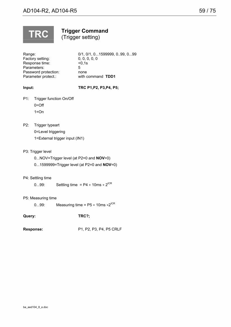
TRC Trigger Command(Trigger setting)
Range: 0/1, 0/1, 0...1599999, 0..99, 0...99Factory setting: 0, 0, 0, 0, 0Response time: <0,1sParameters: 5Password protection: noneParameter protect.: with command TDD1
Input: TRC P1,P2, P3,P4, P5;
P1: Trigger function On/Off0=Off1=On
P2: Trigger typeart0=Level triggering1=External trigger input (IN1)
P3: Trigger level0...NOV=Trigger level (at P2=0 and NOV>0)0...1599999=Trigger level (at P2=0 and NOV=0)
P4: Settling time
0...99: Settling time = P4 ∗ 10ms ∗ 2ICR
P5: Measuring time
0...99: Measuring time = P5 ∗ 10ms ∗2ICR
Query: TRC?;
Response: P1, P2, P3, P4, P5 CRLF

60 / 75
ba_aed104_8_e.doc
Function:
The general function is described in Section 4.2.The position of the trigger level P3 depends on the output scaling (NOV). At NOV=0 (scaling off) the trigger levelwill be on the characteristic 0...1000000. At NOV>0 the trigger level will be in the range 0...NOV.
The response time P4 has to be adjusted, thus the settling time is not lower as of the used filter.
Example 1 : ICR0, ASF3 total settling time >= 160 ms P4 = 16 (= 16 * 10 ms, if ICR=0)
Example 2 : ICR1, ASF3 total settling time >= 160 ms P4 = 8 (= 8 * 20 ms, if ICR=1)
The measuring time P5 provide an additional averaging. (P5=6 averaging over 6 values).
The external trigger will only be released again when the output value has been formed (no re-trigger function).
Important NoteIf the command COF (128..140) was used to select automatic output and the trigger function is activated, thenthe AD104 will output the measured value once after triggering and subsequent measurement. Thus ameasured value query by means of the command MAV? will not be necessary. The connected computer onlyneeds to receive this measured value.

AD104-R2, AD104-R5 61 / 75
ba_aed104_8_e.doc
For details on how to set this mode, see command COF:
COF128 to COF 140 continuous output foll. power On (not for bus operation ).
Example: external triggering with automatical output
1. set parameter of the AED (ASF,ICR,...)
2. activate external Trigger with command TRC1,1,0,20,5;.
3. Define the ouputformat of the meas. values with command COF128+i; . "i" depending on binary output/ASCII-output, see command COF, no parameter setting possible,i after each Trigger event the result isgiven out automatically (without MAV?; command)
4. Stop the automatical measuring value output with STP;.command
5. nonvolatile storage of automatic output in the EEPROM with TDD1; command
6. starts again the automatical output with RES command. After each Trigger event the result is given outautomatically (without MAV?; command)
7. Stop the automatical output with STP; command. Parameter setting is possible
8. Deactivate automatical output with COF3; command
9. Nonvolatile storage of none automatic output (if wanted) with TDD1;
10. Single measuring value output or single trigger output (if wanted) with MSV?; or MAV?;

62 / 75
ba_aed104_8_e.doc
7.5 Error messages
ESR Event Status Register(Output of error messages)
Query: ESR?;
Effect: This function outputs the error messages definedaccording to the IEC standard as 3-digit decimalnumber. The occurring errors are linked by "Or".
Error message Error000 No error004 Not used008 Device Dependent Error (Hardware error, e.g. EEPROM error)016 Execution Error (error at parameter input)032 Comand Error (command not allowed)
Example:024 → Device Dependent Error and Execution Error
After RES, power On or reading the error status, the register contents are cleared.

AD104-R2, AD104-R5 63 / 75
ba_aed104_8_e.doc
7.6 Bus termination for RS-485 version
STR Set Termination Resistor(Bus termination resistors)
Range: 0/1Factory setting: 0 (off)Response time: <15msParameters: 1Password protection: noneParameter protect.: with command TDD1
Query: STR?Effect: 0/1 crlfBefehl: STR0/1;
Effect: 0 = Bus termination switched off1 = Bus termination switched on
The necessary measures for the electrical bus termination (resistors) were described in Section 5.3. Theseresistors protect the zero-signal level on the master line if none of the connected modules is transmitting.Observe here that this bus termination must be switched on only twice per bus system (master line), and isgenerally located at the line ends of the master line.Normally the interface of the master contains such a bus termination and the termination is switched on at themost remote AED via the command STR1;.
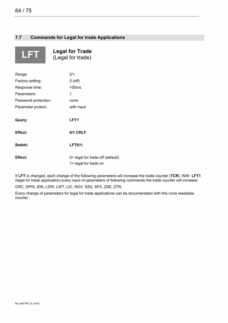
64 / 75
ba_aed104_8_e.doc
7.7 Commands for Legal for trade Applications
LFT Legal for Trade(Legal for trade)
Range: 0/1Factory setting: 0 (off)Response time: <50msParameters: 1Password protection: noneParameter protect.: with input
Query: LFT?
Effect: 0/1 CRLF
Befehl: LFT0/1;
Effect: 0= legal for trade off (default)1= legal for trade on
If LFT is changed, each change of the following parameters will increase the trade counter (TCR). With LFT1(legal for trade application) every input of parameters of following commands the trade counter will increase:CRC, DPW, IDN, LDW, LWT, LIC, NOV, SZA, SFA, ZSE, ZTR,Every change of parameters for legal for trade applications can be documentated with this none resetablecounter.

AD104-R2, AD104-R5 65 / 75
ba_aed104_8_e.doc
TCR Trade Counter(Trade Counter)
Range: no inputResponse time: <30msParameters: nonePassword protection: noneParameter protect.: —
Query: TCR?;
Effect: xxxxxxxx CRLF (8 characters+CRLF)
This is a none resetable counter for legal for trade applications. If LFT is switched on, each change of theparameters will increment the trade counter (see LFT). The maximum count is 8388607 (7F FF FF hex). Thenthe counter is fixed. If this occures you get only overflow values with the command MSV?. The AED has to besend to HBM.
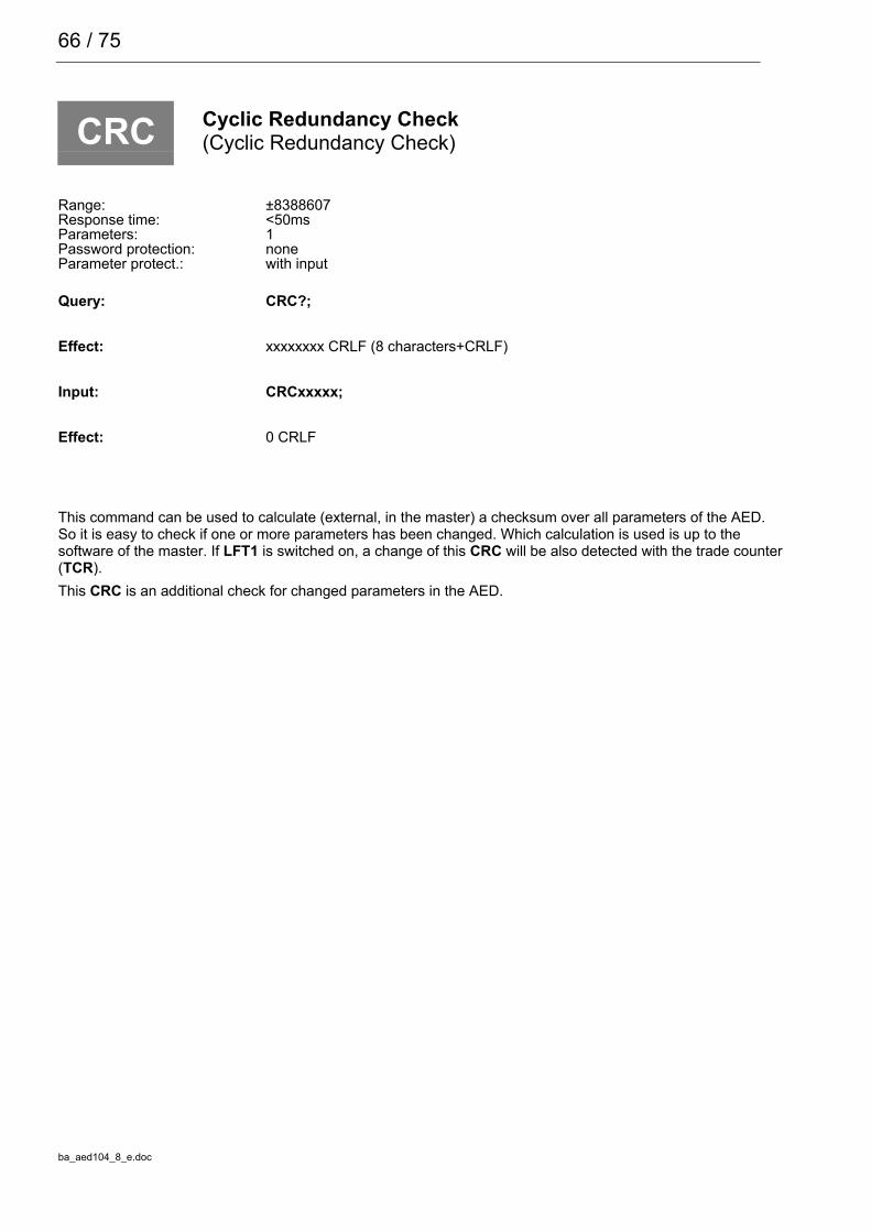
66 / 75
ba_aed104_8_e.doc
CRC Cyclic Redundancy Check(Cyclic Redundancy Check)
Range: ±8388607Response time: <50msParameters: 1Password protection: noneParameter protect.: with input
Query: CRC?;
Effect: xxxxxxxx CRLF (8 characters+CRLF)
Input: CRCxxxxx;
Effect: 0 CRLF
This command can be used to calculate (external, in the master) a checksum over all parameters of the AED.So it is easy to check if one or more parameters has been changed. Which calculation is used is up to thesoftware of the master. If LFT1 is switched on, a change of this CRC will be also detected with the trade counter(TCR).This CRC is an additional check for changed parameters in the AED.

AD104-R2, AD104-R5 67 / 75
ba_aed104_8_e.doc
7.8 Further commands
The commands listed here are contained in the AD104 only for compatibility reasons. They have no functionin the AD104.
ACL? Query ACL, Answer AED: 0GRU? Query GRU, Answer AED: 32COR? Query COR, Answer AED: 0/1ASS? Query ASS, Answer AED: 2CAL Query CAL, Answer AED: 0
The answers are output fixed independent of possible entries.

68 / 75
ba_aed104_8_e.doc
7.9 Examples of communication
Settings for the bus mode (only AD104-R5):The AED is able to work in a bus with up to 32 modules. A prerequisite for this is that each AED is connected tothe bus through a RS-485 interface driver. In this case each AED works as slave, i.e. without request by the busmaster (e.g. PC or PLC), the AED remains inactive on its transmission line. An AED is selected by the mastervia the command SELECT (S00...31). Therefore it is absolutely necessary to enter a communication address foreach AED before the bus coupling. Naturally each address in the bus may be allocated only once.
There are two ways to entry the adrres for communication:1. Connect AED consecutively to the bus:
- Connect first AED to the bus line (The factory setting is ADR31, baud rate 9600)
- Initialize the interface of the master with 9600 Bd, 8, e,1
- Output command ;S31;
- Set wanted address with the command ADR (e.g. ADR01;)
- Select AED with the new address: ;S01;
- Store address nonvolatile with the command TDD1;
- Connect next AED to the bus, output ;S31;, set ADR02, etc.
or2. All AED are interfaced to the bus:
- Read off manufacturing number of the AED (5-digit) (1st AED: xxxxx, 2nd AED: yyyyy, ...)
- Initialize interface of the master 9600 Bd, 8, e,1
- Output broadcast command ;S98;
- Set wanted address with the command ADR (e.g. ADR01,”xxxxx”; )
- Set wanted address with the command ADR (e.g. ADR02,”yyyyy”; ), etc.
- Store addresses nonvolatile with the command TDD1;
Important NoteWith S98; no AED answers, but each AED executes the command.
If there is no communication, then the address or the baud rate can be incorrect.
After successful setting of all addresses and with uniform baud rates, the bus is ready. Now it must bedetermined how the measured values are read out.
With the measured value output via the command MSV?;, the output format must be set previously in allmodules:1. Output broadcast command S98; (all AED execute the command,
but transmit no answer)
2. Output command for the output format (e.g. COF3; for ASCII output)
3. Command TDD1; if this setting should be stored protected against power failure.

AD104-R2, AD104-R5 69 / 75
ba_aed104_8_e.doc
Changing the baud rate:The AED can work with different baud rates. The setting can be changed only through the serial interface withthe aid of the command BDR.Naturally the baud rate of all connected subscribers should be the same in the bus mode. The followingprocedure can be helpful to always certainly set the AEDs in a bus to the wanted baud rate on initialization(switching on) of the system:
1. Set the baud rate of the master interface to 2400 Bd, 8 data bits,1 parity bit even, 1 stop bit
2. Output of the command string: ; (clears the input buffer of the AED)S98; (selects all AED on the bus)BDR9600; (output of the wanted baud rate)
(wait approx. 150ms)
3. Set the baud rate of the master interface to 4800 Bd, 8 data bits,1 parity bit even, 1 stop bit
4. Output of the command string: ; (clears the input buffer of the AED)S98; (selects all AED on the bus)BDR9600; (output of the wanted baud rate)
(wait approx. 150ms)
5. Set the baud rate of the master interface to 19200 Bd, 8 data bits,1 parity bit even, 1 stop bit
6. Output of the command string: ; (clears the input buffer of the AED)S98; (selects all AED on the bus)BDR9600; (output of the wanted baud rate)
(wait approx. 150ms)
7. Set the baud rate of the master interface to 38400 Bd, 8 data bits,1 parity bit even, 1 stop bit
8. Output of the command string: ; (clears the input buffer of the AED)S98; (selects all AED on the bus)BDR9600; (output of the wanted baud rate)
9. Set the baud rate of the master interface to 9600 Bd, 8 data bits,1 parity bit even, 1 stop bit
10. Output of the empty command: ; (clears the input buffer of the AED)
11. Command TDD1; if this setting should be stored nonvolatile.
The output of the semicolon before the S98; command is absolutely necessary, since there can be undefinedcharacters in the input buffer of the AED which, however, are rejected by the reception of the semicolon, due todriving the AED with different baud rates.
Important NoteWith S98; no AED answers but executes the command.With the example listed above, all AED on this bus are set to the baud rate of 9600, independent of theirprevious setting.Naturally another baud rate can also be set. Then the wanted baud rates must be provided in the commandBDR and the initialization of the master interface must be changed accordingly.The baud rate is the transmission speed of the interface. This has no effect on the number of measured valueswhich the AED determines per second.A high baud rate simply enables a larger number of AED to be inquired per time unit in the bus mode.

70 / 75
ba_aed104_8_e.doc
Baud rate Transmission time for one ASCII character2400 4.4 ms4800 2.2 ms9600 1.1 ms19200 0.6 ms
The transmission time for a command string can be calculated approximately with this information. Determinethe number of characters in the command and multiply it with the transmission time. Moreover, the AED has aprocessing time for each command. Refer to the command description for these times (times = transmissionplus processing times).
Determining the bus occupancy (Bus Scan):Frequently it is expedient to determine the bus configuration each time the bus is switched on or if answers ofthe AED are not received. The address occupancy of the bus can thus be determined with the aid of the BusScan. A prerequisite for this is that all modules are set to the same baud rate.
1. Initialization of the master interface with the set baud rate of the AEDs
2. Scanning an address withthe command string: ;S00; (Select Adress)
X; (output of an invalid command)
3. The AED addressed with the address answers with a ‘?CRLF’, since it does not know the command. If noanswer comes after a time of approx. 100ms, then no AED is present at this address. Ifundefined characters or no ? characters are received by the master, then there can be a bus fault or multipleoccupancy of the address. The bus master must react accordingly.
4. Repetition of item 2 with the following addresses 01...31.
If only a few AED are connected and the addresses are known, then the BusScan can naturally only refer tothese addresses. If all AED are determined successfully as bus subscribers, then the identification string of theAED can possibly be read (measuring point identification and manufacturing number).The time-out setting for the interface driver of the master is decisive for the speed of the Bus Scan. The selectcommand requires max. 20...30ms for the output (for 2400 Bd). The AED does not answer to this selectcommand.
Measured value query in the bus mode:All AED have been prepared for bus operation with the aid of the preceding chapter and the BusScan has foundall connected AED.The output format is set with the command COF for the single measured value query with the commandMSV?. The command string is now:S00; MSV?; The AED with the address 00 answers with the measured valueS01; MSV?; The AED with the address 01 answers with the measured value etc.
The following query times result approximately:
Master transmission: S00; MSV?; (9 charact. + 1 charact. pause)Response time AED: approx. 40ms (at ICR2)AED transmissions: xxCRLF (4 characters at COF2)
(10 characters at COF3)
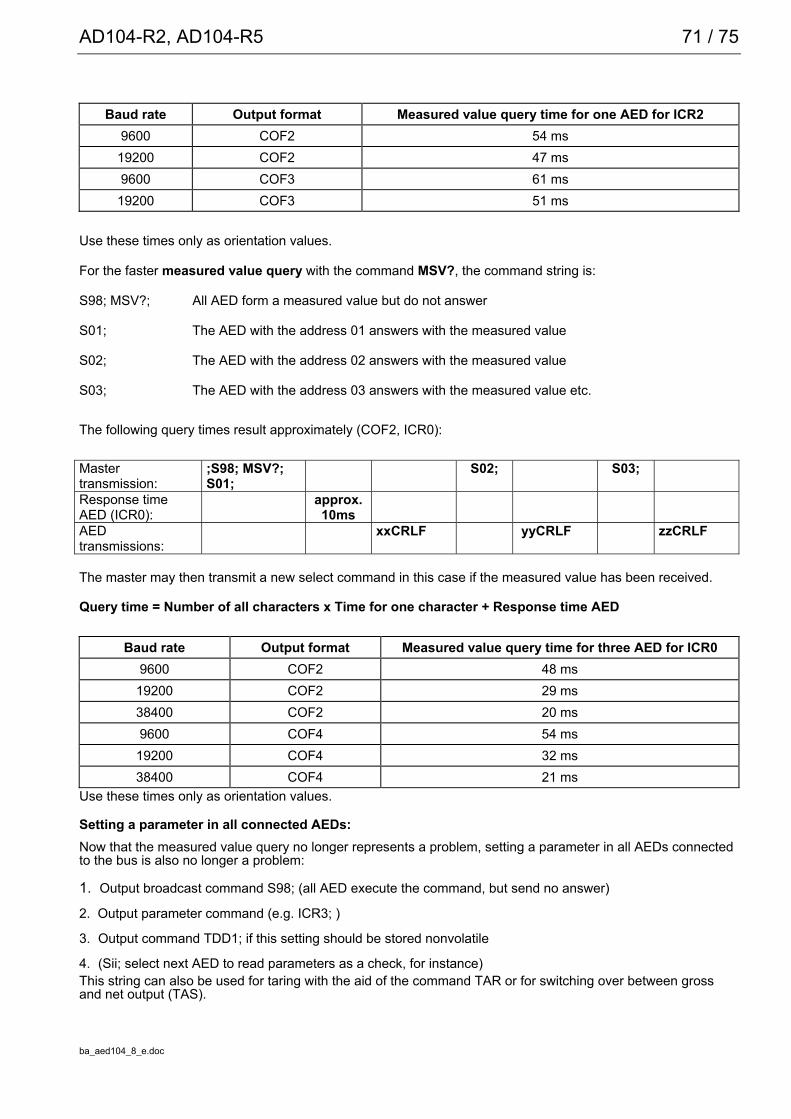
AD104-R2, AD104-R5 71 / 75
ba_aed104_8_e.doc
Baud rate Output format Measured value query time for one AED for ICR29600 COF2 54 ms19200 COF2 47 ms9600 COF3 61 ms19200 COF3 51 ms
Use these times only as orientation values.
For the faster measured value query with the command MSV?, the command string is:
S98; MSV?; All AED form a measured value but do not answer
S01; The AED with the address 01 answers with the measured value
S02; The AED with the address 02 answers with the measured value
S03; The AED with the address 03 answers with the measured value etc.
The following query times result approximately (COF2, ICR0):
Mastertransmission:
;S98; MSV?;S01;
S02; S03;
Response timeAED (ICR0):
approx.10ms
AEDtransmissions:
xxCRLF yyCRLF zzCRLF
The master may then transmit a new select command in this case if the measured value has been received.
Query time = Number of all characters x Time for one character + Response time AED
Baud rate Output format Measured value query time for three AED for ICR09600 COF2 48 ms19200 COF2 29 ms38400 COF2 20 ms9600 COF4 54 ms19200 COF4 32 ms38400 COF4 21 ms
Use these times only as orientation values.
Setting a parameter in all connected AEDs:Now that the measured value query no longer represents a problem, setting a parameter in all AEDs connectedto the bus is also no longer a problem:
1. Output broadcast command S98; (all AED execute the command, but send no answer)
2. Output parameter command (e.g. ICR3; )
3. Output command TDD1; if this setting should be stored nonvolatile
4. (Sii; select next AED to read parameters as a check, for instance)This string can also be used for taring with the aid of the command TAR or for switching over between grossand net output (TAS).

72 / 75
ba_aed104_8_e.doc
8 Technical data
Type AD 104Accuracy with >1.0 µV/d d 3000Bridge resistance, transducer Ohm > 300Bridge excitation voltage V 5Max. Measuring range +/- 2.6 mV/VSensitivity mV/V 2Measuring signal resolution Bit 20 (at 1Hz)Measuring rate(depending on output format and baud rate)
Hz 100; 50; 25; 12; 6; 3; 2; 1
Cut-off frequency of digital filters, adjustable;at -3dBFilter mode 0 (s. ASF)Filter mode 1 (settling time < 240ms), (s. ASF)
HzHz
8... 0.058 ... 3
Cable length between AED and computer withRS232RS-485
mm
< 15< 500
Linearity deviation, related to the nominal value % ± 0.005Temperature effect per 10Kon the zeropoint, related to the nominal valueon the measuring sensitivity, related to the nominal value
%%
± 0.002± 0.005
Serial Interfaceselectrical level AD104-R2 (RS232)electrical level AD104-R5, (RS485,differential)
VV
Low: -3.. -12V High: +3.. 12VLow : B-A < 0.35 High: B-A > 0.35
Baud rate, adjustable Baud 1200; 2400; 4800; 9600; 19200; 38400;Operating voltage (DC) V 5.6...15Current consumption (without transducer) mA < 30 (typ). < 40 (max.)Nominal temperature range oC[oF] -10...+40 [+14...+104]
Service temperature range oC[oF] -10...+50 [+14...122]
Storage temperature range oC[oF] -25...+75 [-13...167]
Dimensions (l x w x h), pcb mm 75 x 29 x 7Dimensions (l x w x h), with housing mm 102 x 31 x 15Weight PCB, approx. g 50Degree of protection EN 60529 in the housing IP 40
In its shielded setup (see Sect. 3), the entire measuring chain including the AED is insensitive against HFinterference and conducted interference in accordance with OIMLR76, EN45501 and EN61326.

ba_aed104_8_e.doc
Modifications reserved. All details describe our products in general form. They are not tobe understood as express warranty and do not constitute any liability whatsoever.
Hottinger Baldwin Messtechnik GmbHPostfach 100151 D-64201 DarmstadtIm Tiefen See 45 D-64293 DarmstadtTel.: +49/6151/803-0 Fax: +49/6151/8039100E-mail: [email protected] · www.hbm.com