ad - defense technical information center "s•curt5y classification m 14. link a link 8 link c...
TRANSCRIPT

AD________
USAARL REPORT NO. 72-15
IMPROVING U. S. ARMY AIRCRAFT PROPELLER AND TAIL ROTOR BLADE
CONSPICUITY WITH PAINT
-4.'i
By
John K. Crosley, MAJ, MSC
Ronald G. Tabak, SP-4
Erwin G. Braun, MAJ, MSC
Robert W. Bailey, COL, MSC
May 1972
U. S. ARMY AEROMEDICAL RESEARCH LABORATORY
Fort Rucker, Alabama
DDC
CrC
De•p tod c ed by A ) ' : " T : ' " : " " "'NATIONAL TECHNICAL .......
INFORMATION SERVICE A,;:,d..: , ,LU S Department of Comn,ntce I..; ".
S,,,gf.l.4 VA 22s15
,,-=

Unclassified
Security Classification
DOCbiMENT CONTROL DATA. R & D)(Secsnity classificatlion of tills, body of abatract and Indexing annoataion muat be entered when the ovegair& pa I. classified.
I. ORIGINATING ACTIVITY (Colpoate SUthor) 28. REPORT SCURITY CLASSIFICATION
U. S. Army Aeromedical Research Laborat.'r) Unclassified
Fort Rucker, Alabama 36360 2b. GROUP
S. RCORT ITLE IMPRCVING U. S. ARMLY AIRCRAFT PROPELLER AND TAIL ROTOR BLADE
CONSPICUITY WITH PAINT
A. CESCRIPTIV6 NOTES (7y"p of repea and bCluelVe date.)
-I. AUTI4ORIS) (Piretthfase. INlde Initial, fear nead)
John K. Crosley, MAJ, MSC Erwin G. Braun, MMJ, MSCRonald G. Tabak, SP4 Robert W. Bailey, COL, MSC
6. REPORT DATE 7a. TOTAL NO. or PAGES 7b. NO. OF REPSMP 1972 18 10
S&. CONTRACT OR GRANT NO. IM. ORIGINATORS REPORT NUVIRURIS)
b.00ROJI[CrtNo. DA Project: No. 3A06211OA819 USAARL Report No. 72-15
a. Work Unit Number 050 (FY 72) e.OTHER REPORT No($) (Any effoeawashen owalmey beaese"~
10. OISTRINUTION STATEMENT
This document has been approved for public release and sale; its distributionis unlimited.
It. SUPPLEMENTARY NOTES It. SPONSORING MILITARY ACTIVITY
U.S. Army Medical R & D CommandWashington, D. C. 20315
IS. A&STRACT
Rotating propellers and tail rotors represent a pctential hazard forpersonnel while aircraft are on the ground. This study was conducted to ascertainif rotating blades could be visually detected more easily by the judicious appli-cation of paint. A total of twenty-two observers rated nine different paintschemes for effectiveness. The results showed that (1) the two schemes presentlybeing used on Army aircraft rated the poorest of all those investigated, and (2)the most nonspizuous scheme was one which had (from the tip toward the hub) afour inch section painted red-orange fluorescent, with the remaining surface di-vided into thirds and painted alternately flat black and gloss white. The blackand white sections of the other half of the blade were reversed to provide a non-concentric pattern.
"'I'ACs DOOM a. I JAN04 WNIC" IS
Di .31o~473 :.11SLUTE FRArmY Use. U2nclas;sifiled5.cUMtt~y asft.

~!
Unclassified"S•cUrt5y Classification m
14. LINK A LINK 8 LINK CKI[Y WORDS - -
ROLM WY ROLEK WT ROLIE %v T
1. Aircraft Paint
2. Helicopter Conspicuity
3. Propeller Visibility
4. Tail Rotor Visibility
--
Unclassified
Steity Chlaslflcatlon

AD
USAARL REPORT NO. 72-r5
IMPROVING U. S. ARMY AIRCRAFT PROPELLER AND TAIL ROTOR BLADE
CONSPICUITY WITH PAINT
By
John K. Crosley, MAJ, MSC
Ronald G. Tabak, SP4
Erwin G. Braun, MlJ, MSC
Robert W. Bailey, COL, MSC
MAY 1972
U. S. ARMY AEROMEDICAL RESEARCH LABORATORY
Fort Rucker, Alabama
U. S. Army Medical Research and Development Command
Distribution Statement. This document has been approvedfor public release and sale; its distribution is unlimited.
iC-

ACKNOWLEDGMENT
The authors wish to convey their sincere appreciation to Mr.
Douglas Carter, Illustrator, Mr. John Barbaccia, Chief of Photography
and Illustration Branch, and those individuals who volunteered to serve
as observers for this study.
li

ABSTRACT
Rotating propellers and tail rotors represent a potentialhazard for personnel while aircraft are on the ground. This stuaywas conducted to ascertain if rotating blades could be visually de-tected more easily by the judicious application of paint. A total oftwenty-two observers rated nine different paint schemes for effective-ness. The results showed that (1) the two schemes presently being usedon Army aircraft rated the poorest of all those investigated, and (2)the most conspicuous scheme was one which had (from the tip toward thehub) a four inch section painted red-orange fluorescent, with the re-maining surface divided into thirds and painted alternately flat blackand gloss white. The black and white sections of the other half of thebldde were reversed to provide a non-concentric pattern.
APPROVED:
Commanding
iii
TABLE OF CONTENTS
Page
I. PURPOSE - 1
II. BACKGROUND ----------------------------------------- 1
III. METHODOLOGY ----------------------------------------- 4
Figure 1 -------------------------------------- 6
IV. DISCUSSION ----------------------------------------- 7
Figure 2 -------------------------------------- 8
V. RESULTS ------------------------------------------ 9
Table IA -------------------------------------- 10
Table IB -------------------------------------- 12
Table IIA -------------------------------------- 13
Table IIB -------------------------------------- 14
Table IIIA -------------------------------------- 16
Table IIIB --------------------------------------- 17
Literature Cited 18
DD Form 1473
iv

IMPROVING U. S. ARMY AIRCRAFT PROPELLER AND TAIL ROTOR BLADE
CONSPICUITY WITH PAINT
I. PURPOSE
Although no reference has been found, there is no doubtthat Orville and Wilbur Wright were aware of the potentialhazards associated with their revolving aircraft propeller.Since that time, many individuals have had physical contactwith turning propellers, with the individual seldom emergingunscathed. Since the advent of the helicopter, the high speedtail rotor blade has introduced an additional hazard for thoseassociated with aviation.
The purpose of this study is to investigate ways andmeans of improving the conspicuity of these revolving devicesand thereby, hopefully, reduce the probability of an accident.
II. BACKGROUND
Previous studies1,2,3 by this Laboratory have dealt withoverall aircraft conspicuity as a Oeterrent to the midair col-lision problem. In the course of these studies, the works ofLazo I , Malone 6 , 7 , Applied Psychology Corporation8 , Middle-ton9 , and others were reviewed.
One approach to increase aircraft attention-getting wasmade by a series of studies to develop patterns by the judiciousapplication of paints to the fuselage of fixed and rotary wingaircraft as well as the main rotor blades of the latter. Thepaint schemes selected for fleet application were the result ofthis research and field studies conducted in the operationalenvironment utilizing the best possible scientific methodsavailablel,
2 .
The use of paint as an engineering variable was basedupon providing peak visual stimulation by maximizing:
(a) Color contrast within the propeller blade scheme.

(b) Color contrast between the aircraft or propellerand the backktound.
(c) Brightness contrast within the color scheme.
(d) Brightness contrast between the aircraft orpropeller and the background.
(e) The visual stimulus effecc of pattern by inducingmotion or flicker.
(f) The rotational speed of the blades.
(g) The retinal area considered.
These variables were given prime consideration in the originalstudies dcaling with helicopter main rotor blades and aircraftfuselages. They are equally applicable to helicopter tail rotorblades &H fixed wing aircraft propellers.
In Lazo's 3 original study, a scheme incorporating black,white and red located concentrically on the propeller blade offixed wing aircraft was found to be superior to all otherstested. In our in-flight studies '9 dealing with helicoptermain rotor blades, we found that modifying the proportionateareas of the blade painted and using a fluorescent red-orangepaint in place of gloss re4 lacquer, improved conspicuity signi-ficantly.
Based upon our recommendations, the upper surfaces of themain rotor blades of the helicopter training fleet (approximate-ly six hundred aircraft) located at Fort Rucker, Alabama werepainted with the superior scheme. For the subsequent four yearperiod, daytime midair collisions have fallen from an average offourteen per year to one per year. Although there is no way todetermine the exact contribution of painted blades to thissafety improvement, pilot acceptance has been exceptionally highand the accident record notable. During this four year periodit has been necessary to modify the original paint scheme some-what. It was found that the fluorescent paint:
(1) Became a gummy, viscous layer that tended to shiftposition on the blade after coming in contact with ever-present transmission fluid. It is not unusual for aquantity of this fluid to be on the blade, and the asso-ciated shift in paint position adversely affected thebalance and tra6king of the blade.
2

(2) In the gtminy state, tended to attract debris whichfucther contributed to the blade imbalance problem.
(3) Faded and became ineffective two to four monthsafter exposure to sunlight.
(4) Significantly increased the maintenance upkeep costsfor each aircraft.
After duly considering the above facts, it was decided torecommend the second best rank order paint scheme which incor-porated gloss yellow lacquer in place of the red-orange fluores-cent material. Although the overall conspicuity was somewhatreduced, the use of the lacquer resolved the maintenance problemsand was considered a reasonable compromise. In terms of acci-dent rates, this substitution appears not to have adverselyaffected our previous results, at least at the training baseswhere a high density of helicopter traffic exists and our recom-mended scheme has been applied.
It should be noted that in addition to fluorescent paints,we evaluated fluorescent tapes on the aircraft. These tapeshave a reported effective life of twenty-four to forty-eightmonths while exposed to sunlight. Installation of tape on themain rotor blade was not found to be feasible due to a tendencyto peel after a few hours. However, installation on the fuse-lage, to date, has been successful and longevizy studies arepresently being conducted on this application technique.
In reference to the inherent personal danger associatedwith fixed wing propellers and helicopter tail rotors, we haveobtained the most recent injury-fatality data availab'le fromthe U. S. Army Agency for Aviation Safety (formerly the U. S.Army Board for Aviation Accident Research). During the period1 January 1967 to 15 August 1971, the Army has had four propel-ler strikes. These are broken down as follows:
(a) Period - Day (2), Night (2)
(b) Injury unknown - 1 (propeller struck rifle)
(c) Fatalities - three
Md) Aircraft involved - U6-A (Beaver) - 3OV-l (Birddog) - 1
For the same time frame, there have been thirty-one tail
3
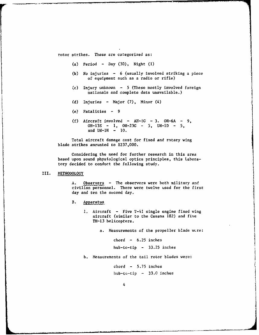
rotor strikes. These are categorized as:
(a) Period - Day (30), Night (1)
(b) No injuries - 6 (usually involved striking a pieceof equipment such as a radio or rifle)
(c) Injury unknown - 5 (These mostly involved foreignnationals and complete data unavailable.)
(d) Injuries - Major (7), Minor (4)
(e) Fatalities - 9
(f) Aircraft involved - AH-tG - 3. OH-6A - 9,OH-13E - 1, OH-23G - 3, UH-1D - 5,and UH-IH - 10.
Total aircraft damage cost for fixed and rotary wingblade strikes amounted to $237,000.
Considering the need for further research in this areabased upon sound physiological optics principles, this Labora-tory decided to conduct the following study.
III. METHODOLOGY
A. Observers - The observers were both military andcivilian personnel. There were twelve used for the firstday and ten the second day.
B. Apparatus
1. Aircraft - Five T-41 single engine fixed wingaircraft (similar to the Cessna 182) and fiveTH-13 helicopters.
a. Measurements of the propeller blade w(re:
chord - 6.25 inches
hub-to-tip - 33.25 inches
b. Measurements of the tail rotor blades were:
chord - 5.75 inches
hub-to-tip - 33.0 inches
4

NOTE: A small portion (4.50 inches) of the tail rotoradjacent to the hub was not painted since this area mustbe fluxed for inspection.
2. Paints used in this study were as follows:
a. WhiLe, lacquer, gloss, color number 17875
b. Black "Velvet Coating" manufactured by the3-M Corporation having a reflectance valueof approximately 1.5 percent.
c. Red-orange fluorescent "Day-Glo", color
number 633
d. Yellow, lacquer, gloss, color number 13538
e. Red, lacquer, gloss, color number 11136
3. Paint schemes developed for use in this study areshown in Figure 1.
C. Procedure
1. This project was conducted on two separate days.The first day involved the comparison of propellerblades in the morning and tail rotor blades in theafternoon. The second day, only propeller blades wereused. The test propellers and blades were observedagainst the following backgrounds:
a. Buildings and other ramp-parked aircraft.
b. Open runway viewing with sky being theprimary background.
c. Green trees with the aircraft on or adjacentto green grassy areas.
2. The propellers were observed while rotating at 600and 1200 revolutions per minute as indicated on theaircraft tachometer. This approximately correspondsto, respectivly, ground idle and fast idle or "run up"speed for the T-41 aircraft. The tail rotors were ob-served while rotating at 2400 and 3200 engine
5

COLOR UB BLACK ;
DAY 1 (26 AUG 71) CODO: BLWIT
CODE: E WHITE
P L COLORS AS INDICATEDPROPELLERS:
A B C D EYellow
Yellow Red-Orange Red
/i
Fi
ROTOR BLADES:A B C D E F
YellowYellow Red- Red.
Orange
DAY 2 (31 AUG 71) PROPELLERS ONLY:
A' B, C' D' E'Yellow
Red-Orange
Figure 1.
6

revolutions per minute. This corresponds to ground idleand operating speed for the TH-13 helicopter.
3. While the blades were rotating At the lower range,the observers were instructed to compare all of themsimultaneously from a distance of approximately onehundred feet. They then approached to within five feetof the aircraft and viewed each revolving blade bothdirectly and peripherally, marking their response sheetat this time. This procedure was repeated for bothblade speeds and with each type of background.
4. Each observer received a rating sheet (Figure 2)which required that they make a "forced choice" decision,rating the schemes from 1 (best) to 5 (poorest). Theobservers were instructed to avoid any discussion oftheir ratings until completion of the project.
5. The aircraft were identified by a letter marked onthe fuselage. The rating sheets randomly presentedthese letters for selection and the random sequence wasdifferent for each background.
IV. DISCUSSION
1. During the initial observations of the T-41 aircraftthe first day, "A" aircraft, having the standard painted pro.-peller, caught fire. This was immediately extinguished and thefirst background observations completed. While making observa-tions against the second background it caught fire again andsustained extensive damage necessitating that it be eliminatedfrom the remainder of the study. Sufficient data was collectedfrom these observations to conclude that this scheme was thepoorest of those being presented.
2. Weather conditions were:
a. First day - The sky was fairly heavy overcastfor the propeller observations in the morning. The tail rotorobservations in the afternoon were made under essentially clearsky conditions.
b. Second day - There were scattered clouds withlight overcast during the second propeller blade observations.
7

Name Date 26 August 1971
PROPELLER CONSPICUITY QUESTIONNAIRE
BACKGROUND
Other Aircraft,Tree Line Open Field Buildings, etc.
RPM 600 1200 RPM 600 1200 RPM 600 1200
B D E
C E B
D A C
A B D
E C A
Name Date 26 August 1971
TAIL ROTOR CONSPICUITY QUESTIONNAIREBACKGROUND
Other Aircraft,
Tree Line Open Field Buildings, etc.
RPM 2400 3200 RPM 2400 3200 RPM 2400 3200
B D F
C E B
D A C
A F D
E C A
F B EZ I
Name Date 31 August 1971
PROPELLER CONSPICUITY QUESTIONNAIRE
BACKGROUNDOther Aircraft,
Tree Line 0 en Field Building setc.S RPM 600 200RPm -6"00- 120O0:
RPM 600 1200 RPM
B' D' E' !C' E' B'1Z1)' A' C'
A\ B] D'
E'C' A'_____
Figure 2
--8--
_ I

3. While observations were being conducted the morningof the first day (T-41), it was hypothesized that perhaps adifferent scheme involving the use of black and white sectionspainted non-concentrically to induce the perception of movementmight increase visual stimulation. A blade was repainted toevaluate this hypothesis and the results indicated that it wasindeed quite conspicuous. Therefore it was decided to modifythe design to include this scheme in the remaining test matrix.Since the standard paint scheme used for most helicopter tailrotors by the Army is very similar to the red-black-white schemein this study, this scheme ("E") was repainted to scheme "F"(see Figure 1). For scheme "E" it was decided to simply turnone of the helicopters around and present the standard schemewhich is also painted on the opposite side of the blade. Theresults of the study indicate that this standard scheme usingred-black-white was the poorest of those presented.
4. Based upon the information obtained during the firstday of tail rotor blade observations, it was decided to comlarethe three best schemes selected with two additional schemesutilizing the non-concentric patterns of black and white. Thiswas accomplished on the second day using T-41 propeller blades(see "Day 2", Figure 1).
5. Photographic coverage included 16mm color movies and35mm slides. The original speed at which the movies were takenwas 64 frames per second (fps). The results indicated that64 fps was much too fast since the blades appear stroboscopicin pattern. The 24 fps was much better, but still possiblycould be improved by shooting at 16 fps or 8 fps to provide aphotographic reproduction move nearly resembling the live visualexperience.
V. RESULTS
Table IA shows the averaged responses of the preferencestudy made on the first set of painted propeller blades on 26August 1971. It is important to remember that the lower thenumber in a particular column, the higher the ranking of thatcolor scheme. Color scheme "C" is by far the most conspicuousof the five tested under every condition of background andengine RPM except where we have a tree line associated with anRPM of 1200. In this case, "D" is ranked slightly higher, in-dicating thaL in certain instances of higher blade speed thereis probably a change in the relative conspicuity of the twopatterns.
9

TABLE IA
Preference Study of Painted Propellers
Averaged Responses - Part 1
(n = 13)
Background: Tree Line Open Field Buildirgs & A/C
RPM*: 600 1200 600 1200 600 1200
Color SchemeTotal Rank
A 4.9 4.8 4.85
B 3.7 3.6 4.0 4.0 3.5 3.7 3.75
C 1.2 1.9 1.5 1.6 1.0 1.0 1.37
D 2.1 1.2 1.9 1.9 2.5 2.2 1.97
E 3.0 3.2 2.6 2.5 3.1 3.2 2.93
I
(* denotes engine RPM.)
10

Although we were able to test color scheme "A" onlyagainst a background of buildings and aircraft because of afire in this particular aircraft, it definitely appears to bethe least effective of the five. In the last column, whichgives the total rank of all the patterns averaged over allbackgrounds and RPM's, "B" was ranked fourth, "E" was third,"D" was second, and "C" was the best.
Table IB gives the results of the statistical analysis ofthe preference study of the same five color schemel that wereconsidered in Table IA. The values obtained for X ranks are solarge that a definite color effect exists. There is less thanone chance in a thousand that the results obtained could be theresult of chance alone.
In order to determine the extent to which the observersagreed in their preferences, Kendall'sI 0 statistic, W, the"coefficient of concordance", was computed for every combina-
tion of background and rotational speed. Basically, W is de-fined as the variance of rank sums divided by the maximumpossible variance of rank sums. The range of W is from 0 to 1.If W = 1, there is complete agreement among the judges; if W =0, complete disagreement. In this study, W varied from 69% to81%, with its average value (W)av, being 74%. This indicatesthat there is apparently a fairly high degree of "concordance"among the thirteen observers.
Kendall's statistic is related to the average intercorre-lation between the rankings assigned by the observers and thisrelationship is given by
F = (nW-1)/(n-1),
where n is the number of observers. While W corresponds to acorrelation ratio, the average correlation coefficient, F,correspond1 3 to a rank-difference correlation. Taking all of thepossible (2) or 78 pairs of observers, we find that the averagerank correlation runs from about 0.67 to 0.80 with an averageof 0.71. Thus, we can say that in the majority of instancesobserver-pairs do give relatively similar rankings.
Tables IIA and IIB give the results of the preferencestady of the second set of painted propeller blades which wereobserved on 31 August 1971. It is quite obvious that colorscheme D' represents the pattern rated the highest in conspi-cuity under all conditions, while A' and E' were rated thelowest. Again, the X2 -test demonstrates that there is a
11

TABLE IB
Preference Study of Painted Propellers
Analysis of Variance - Part I
Background: Tree Line Open Field Buildings & A/C
RPM2
600 x ranks = 27.00 X ranks = 28.66 X ranks = 42.27
W = 0.6923 W = 0.6923 W = 0.8130
F = 0.6667 F = 0.6667 F = 0.7974
2 2 2
1200 X ranks 29.03 X ranks 27.00 X ranks = 40.52
W = 0.7443 W = 0.6923 W = 0.7793
F = 0.7230 F = 0.6667 F = 0.7609- *1
(W) = 0.7356av
(F) = 0.7136,av
whereW = coefficient of concordance
F = average correlation coefficient
12

TABLE hA
Preference Study of Painted Propellers
Averaged Responses - Part 2
(n = 10)
Background: Tree Line Open Field Buildings & A/C
RPM*: 600 1200 600 1200 600 1200
Color SchemeTotal Rank
A' 3.8 3.2 4.1 4.1 3.7 3.3 3.70
B' 2.3 2.2 2.4 2.1 2.5 2.3 2.30
C' 3.2 3.7 2.8 3.3 2.9 3.3 3.20
D' 1.2 1.1 1.1 1.1 1.2 1.3 1.17
El 4.5 4.8 4.5 4.4 4.7 4.8 4.62
* - denotes engine RPM as indicated by the aircraft tachometer.
13

TABLE IIB
Preference Study of Painted Propellers
Analysis of Variance - Part 2
Background: Tree Line Open Field Buildings & A/C
PPM
2 2 2600 X ranks = 26.64 X ranks = 27.48 X ranks = 27.52
W = 0.6660 W = 0.6870 W = 0.6880
F = 0.6289 F = 0.6522 F = 0.6533
2 X2rak 2
1200 X ranks = 32.08 X ranks = 30.72 X ranks = 27.20
W = 0.8020 W = 0.7680 W = 0.6800
F 0.8911 F = 0.7422 F = 0.6444
(W) 0.7152av
(F) = 0.70201av
14

definite color effect at the 0.999 probability level. Both W andF are around the 70% level, so there is a moderately high level ofagreement among the observers.
In Tables IliA and IIIB we consider the results of the preferencestudy of painted tail rotor blades in which the same five colorschemes were used as in Table I, but with the addition of one morepattern, F. Color scheme F was by far the most superior of any ofthe six patterns used under all conditions, while patterns A and Ewere the worst. One interesting fact is the reversal of the rank-ings of C and D when compared to the preference study of the paintedpropellers. It appears that D is more conspicuous at the higherspeeds of the tail rotor than C is, although there may be a smalleffect due to the difference in area between the tail rotor and theT-41 propellers.
The values of X 2ranks are significant at t*e 99.9% level, de-noting a very definite color effect. The average values of W and Fare around 3.85, indicating a high degree of agreement among the 13observers.
It was apparent after the first day of observations that thescheme using concentric black and white sections (1/6) of the bladesurface, and the scheme using "Da--Glo", white and black were theprimary choices.
Observations on the second day revealed that the superior schemewas D', Figure 1. It was shown in the study that color contrast wassignificant under certain background conditions. Therefore, basedupon the results of this study and an application of past experi-ence, the recommended pattern for blade and tail rotor painting is asfollows (in order of preference):
1. From the blade tip to the hub, paint a four inch area ofred-orange fluorescent ("Da-Glo"), while dividing the remain-ing surface into thirds and painting alternately flat blackand g 5ss white. The black and white sections of the otherhalf of the blade are reversed to provide a non-concentricpattern. This scheme would be the best provided the "Da-Glo"were repainted every 3 - 4 months. This latter problemmay or may not be a major consideration.
2. Same as scheme in Paragraph 1 above, eAcept substituteyellow lacquer paint for "Da-Glo."
3, Same as scheme in Paragraph 1 above, except leave offthe colored tip.
15

TABLE IIIA
Preference Study of Painted Tail Rotors
Averaged Responses
(n = 12)
Background: Tree Line Open Field Buildings & A/C
RPM*: 2800 3200 2800 3200 2800 3200
Color SchemeTotal Rank
A 5.6 5.7 5.8 5.8 5.8 6.0 5.78
B 3.9 3.8 4.0 4.0 4.0 3.9 3.93
C 2.2 2.6 2.4 2.3 2.8 2.8 2.52
D 2.9 2.3 2.1 2.1 2.2 2.1 2.28
E 5.4 5.3 5.2 5.0 5.1 4.8 5.13
F 1.3 1.3 1.5 1.8 1.3 1.5 1.45
* - denotes engine RPM as indicated by the aircraft tachmoter.
16

TABLE IIIB
Preference Study of Painted Tail Rotors
Analysis of Variance
Background: Tree Line Open Field Buildings & A/C
RPMr nj[ 2 2 22400 X ranks = 58.69 X ranks 50.36 X ranks = 52.19
W = 0.9782 W 0.8393 W = 0.8699
F = 0.9762 F 0.8247 F = 0.8581
32002 2 2ranks = 51.48 X ranks = 49.29 X ranks = 49.91
W = 0.8580 W = 0.8214 W = 0.8318
F = 0.8451 F = 0.8052 F = 0.8165
(W) 0.8664av
(F) = 0.8543av
17

LITERATURE CITED
1. Bynum, J. A., Bailey, R. W., Crosley, J. K., and Nix, M.S., Jr.Development of a Paint Scheme for Increasing HelicopterConspicuity, Report No. 68-1, U. S. Army AeromedicalResearch Laboratory, Fort Rucker, Alabama, September 1967.
2. Crosley, J. K., Bailey, R. W., and Nix, M. S., Jr. ImprovingHeliccpter Conspicuity Through the Use of Painted MainRotor Blades, Report No. 68-2, U. S. Army AeromedicalResearch Laboratory, Fort Rucker, Alabama, October 1967.
3. Crosley, J. K., McLean, W. E., Tabak, R. G., and Bailey, R. W.The Use of High Intensity Xenon Lighting to EnhanceU. S. Army Aircraft Day/Night Conspicuity, Report No.71-13, U. S. Army Aeromedical Research Laboratory, FortRucker, Alabama, January 1971.
4. Lazo, J. Investigation of Color Schemes to Improve PropellerNoticeability. Report XG-T-213, Naval Air Materiel Center,May 1954.
5. Lazo, J., and Bosee, R. A. Visibility Factors in AircraftCollision Avoidance. Aerospace Medicine, 1961, 32,pp634-638.
6. Malone, F. L., Sexton, M. S. and Farnsworth, D. The Detecta-bility of Yellows, Yellow-Reds, and Reds in Air-SeaRescue. MRL No. 182, pp 1 7 7 - 1 8 5 (Color Vision Report No. 25),U. S. Navy Department.
7. Malone, F. L. A Preliminary Field Evaluation of the RelativeDetectability of "olors for Air-Sea Rescue. MRL No. 237,XI1 No. 22, U. S. Navy Department.
8. Applied Psychology Corporation, The Role of Paint in Mid-AirCollision Prevention, Final Report No. ', under FederalAviation Contract FAA/BRD-127, December 1961.
9. Middleton, W. E. K. The Colors of Distant Objects. J. Opt.Soc. Amer., 1950, 40, p. 3 7 3 .
10. Siegel, Sidney. Nonparametric Statistics, McGraw-Hill, 1956.
18