ad-a283 979 - defense technical information center · ad-a283 979 imiscellaneous paper gl-94-32 ......
TRANSCRIPT

AD-A283 979iMiscellaneous Paper GL-94-32
13~Ih~hIf"" August 1994
US Army Corpsof EngineersWaterways ExperimentStation
Airfield Pavement Evaluation,Bradshaw Army Airfield,Pohakuloa Training Area, Hawaii
by William P. Grogan
DTICELECTESEP 02 199411
F•
Distribution is authorized to U.S. Government agencies only;test and evaluation; August 1994. Other requests for this documentshall be referred to Headquarters, U.S. Army Corps of Engineers(CEMP-ET), Washington, DC 20314-1000.
,• 94-28612 DT18 QUALT INSPECED 5A<,• Ill Will i IllH EU IIII --\&)'""''+
949 01 233Prepared for U.S. Army Center for Public Works

DESTRUCTION NOTICE-For classified documents,follow the procedures in DoD 5200,22-M, IndustrialSecurity Manual, Section 11-19 or DoD 5200.1-R,Information Security Program Regulation, Chapter IX. Forunclassified, limited documents, destroy by any method thatwill prevent disclosure of contents or reconstruction of thedocument.
The contents of this report are not to be used for advertising,publication, or promotional purposes. Citation of trade namesdoes not constitute an official endorsement or approval of the useof such commercial products.
PRIWIrD ON RECYCLED PAPER

Miscellaneous Paper GL-94-32August 1994
Airfield Pavement Evaluation,Bradshaw Army Airfield,Pohakuloa Training Area, Hawaiiby William P. Grogan
U.S. Army Corps of EngineersWaterways Experiment Station3909 Halls Ferry RoadVicksburg, MS 39180-6199
Accez.ioiý For
NTIS CRA&IDTIC TABU,:anjioL,-cedJustification
ByDistribution I
Availability Codes
Final report DIst Avail and I ori SpecialDistribution is authorized to U.S. Government agencies only; Itest and evaluation; August 1994. Other requests for this documentshall be referred to Headquarters, U.S. Army Corps of Engineers 1 I3(CEMP-ET), Washington, DC 20314-1000.
Prepared for U.S. Army Center for Public WorksAlexandria, VA 22310-3860

US Army Corpsof Engineers N
Waterways Experiment "
WtaterasEprmetSainCtaoonI-u~a~nDt""PAN&= OADWA LDIONEOM
Grogan, Willam P• iUWATUA o&7~f 8TAT
Airfield pavement evaluation, Bradshaw Army Airfield, PohakuloaTraining Area, Hawaii / by William P. Grogran ; prepared for U.S. ArmyCenter for Public Works.
52 p. •ill. ; 28 cm. - (Miscellaneous paper ; GL-94-32)"Distribution limited to U.S. Government agencies only ..."Includes bibliographic references.1. Runways (Aeronautics) - Hawaii - Evaluation. 2. Pavements -
Hawaii - Testing. I. United States. Army. Corps of Engineers. II. U.S.Army Engineer Waterways Experiment Station. Ill. GeotechnicalLaboratory (U.S.) IV. U.S. Army Center for Public Works. V. Title. VI.Series: Miscellaneous paper (U.S. Army Eng;nee" Waterways Experi-mrent Station) ; GL-94-32.
TA7 W34m no.GL-94-32

Contents
Preface................................................v
Executive Summary ...................................... vii
1-Introduction ......................................... 1
Background ......................................... I1Objective and Scope ................................... 1
2-Pavement Load-Carrying Capacity ......................... 3
General ............................................ 3Load-Carrying Capacity ................................. 4
3-Recommendations for Maintenance, Repair,
and Structural hnprovement ................................ 7
General ............................................ 7Recommendations ..................................... 8
4--Conclusions ......................................... 13
General ............................................ 13Structural Capacity and Condition Ratings .................... 13
References ............................................ 15
Appendix A: Background Data .............................. Al
Description of the Airfield ............................... AlPrevious Reports ...................................... AlDesign and Construction History ........................... AlTraffic History ....................................... A2
Appendix B: Tests and Results .............................. BI
Tests Conducted ...................................... B IDynamic Cone Penetrometer Tests .......................... B I
Appendix C: Pavement Condition Survey and Results .............. Cl
Pavement Condition Survey .............................. ClAnalysis of PCI Data ................................... C2
iii1

Appendix D: Structural Analysis ............................ DI
General ............................................ D IACN-PCN Method of Reporting Pavement Structural Condition ..... D2Determination of CBR for Analysis ......................... D2PCN Analysis ........................................ D3Example Problem ..................................... D4Solution ............................................ D5
Appendix E: Micro PAVER Output Summary ................... El
SF 298
iv

Preface
This report provides an assessment of load-carrying capacity and conditionof airfield pavements at Bradshaw Army Airfield, Hawaii. This reportprovides data for the following functional activities:
a. Plan and program for pavement maintenance, repairs, and structural
improvements.
b. Design maintenance, repair, and construction projects.
c. Determine airfield operational capabilities.
d. Provide information for aviation flight publications and missionplanning.
Users of information from this report include installation Directorate ofPublic Works (DPW), engineering design agencies (DPWs, U.S. Army Corpsof Engineers), installation airfield Commanders, U.S. Army AeronauticalServices Agency (USAASA), and agencies assigned operations planningresponsibilities. Information concerning aircraft inventory, passes andoperations shall not be released outside U.S. Government agencies. Thisreport satisfies requirement for condition inspection and structural evaluationestablished in Army Regulation AR 420-72 (Headquarters, Department of theArmy 1991) and supports airfield survey requirements identified inAR 95-2(Headquarters, Department of the Army 1988).
The Army Airfield Pavement Evaluation (AAFEVAL) Program is managedby the U.S. Army Center for Public Works (CECPW-ER) and technicallymonitored by the U.S. Army Corps of Engineers Transportation SystemsCenter (CEMRD-ED-IT) located in Omaha, Nebraska. Funding for this air-field evaluation was provided by CECPW-ER.
This publication was prepared by the U.S. Army Engineer WaterwaysExperiment Station (WES) based upon pavement structural testing, andcondition survey work at Bradshaw Army Airfield, Hawaii, on 24 February1994. The survey team consisted of Messrs. William P. Grogan, DennisMathews, and Rogers Graham of the Pavement Systems Division (PSD),Geotechnical Laboratory (GL). Mr. Robert W. Grau, PSD, was theAAFEVAL Program Manager at WES. The publication was prepared by
V
Mr. Grogan under the supervision of Mr. J. W. Hall, Chief. Systems AnalysisBranch, PSD, and Dr. George Hammitt 11, Chief, PSD. General supervisionwas provided by Dr. W. F. Marcuson III, Director, GL, WES.
At the time of publication of this report, Director of WES wasDr. Robert W. Whalin. Commander was COL Bruce K. Howard, EN.
Recommended changes for improving this publication in content and/or for-mat should be submitted on DA Form 2028 (Recommended Changes to Publi-cations and Blank Forms) and forwarded to U.S. Army Center for PublicWorks, ATTN: CECPW-ER, 7701 Telegraph Road, Alexandria, VA 22310-3862.
The contents of this report are not to be used for advrtising, publication,or promotional purposes. Citation of trade names dos not constitute anofficial endorsement or approval for the we of such comnercial products.
vi

Executive Summary
The field testing at Bradshaw Army Airfield, Pohakuloa Training Area,Hawaii was conducted during February 1994 by the U.S. Army EngineerWaterways Experiment Station (WES), Vicksburg, MS. The structuralcapacity and physical properties of the pavement were determined fromdynamic cone penetrometer (DCP) tests. A surface inspection of the airfieldwas also conducted to establish the condition of the airfield surface as opposedto its load carrying capacity.
The results of the tests and visual inspection reveal the following:
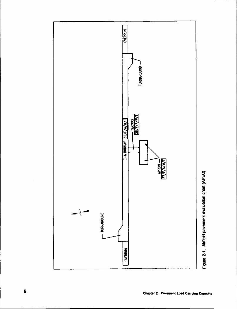
a. The airfield pavement facilities and their assigned PCN are:Runway 09-27, 36/F/A/W/T; Taxiway, 36/F/A/W/T; and Apron27/F/A/W/T. An airfield pavement evaluation chart (APEC) showingthe facilities and the PCN for each facility is shown in Figure 2-1.
b. The airfield is structurally adequate to support day to day missionrequirements (i.e. peacetime use) for 20 years.
c. The surface condition of the Apron indicates that maintenance andrepair (M&R) will be required. The M&R suggested in Chapter 3should be planned now and accomplished within the next two years inorder to prevent further deterioration.
d. In planning structural improvements and/or reconstruction requirements,it should be recognized that ETL 1110-3-393 (Headquarters,Department of the Army, 1988) specifies that portland cement concrete(PCC) or composite pavements with a rigid overlay be used innumerous airfield pavement areas, such as the ends of all runways,primary taxiways, and primary parking aprons.
d. Overloading the pavement facilities may shorten the life expetancy.
Additional details on structural capacity, surface condition and work requiredto maintain and strengthen the airfield are contained in Chapters 2and 3 of this report.
vii

1 Introduction
Background
In May 1982 the Department of the Army initiated a program to determineand evaluate the physical properties, the load-carrying capacity for variousaircraft, and the general condition of the pavements at major U.S. Army air-fields. The evaluation of the airfield pavements was performed to determinethe structural adequacy of the existing pavements to accommodate missionaircraft and to identify maintenance, repair and construction workrequirements.
Objective and Scope
The primary objectives of this investigation were to determine theallowable aircraft loads, and to identify maintenance, repair and structuralimprovement needs for each airfield pavement feature. These objectives wereaccomplished by:
a. Obtaining records of day-to-day traffic operations from the airfieldoperations personnel.
b. Performing a structural evaluation of the airfield pavements inaccordance with TM 5-826-1/AFM 88-24, Chap. 1 (Headquarters,Departments of the Army and the Air Force 1988); TM5-826-2/AFM88-24, Chap. 2 (Headquarters, Departments of the Army and the AirForce 1990), using the dynamic cone penetrometer device.
c. Performing a condition survey to determine pavement distresses (type,severity and magnitude) in accordance with TM 5-826-6/AFR 93-5(Headquarters, Departments of the Army and the Air Force, 1989) andusing analysis features of the MicroPAVER pavement managementsystem.
Chapter 1 Introduction

The results of this study can be used to:
a. Provide preliminary engineering data for pavement design(Appendixes A and B).
b. Assist in identifying and forecasting maintenance and repair work, thepreparation of long range work plans, and programming funds for thevarious work classification categories (Appendixes C and D).
c. Determine type and gross weights of aircraft that can operate on a givenairfield feature without causing structural damage or shortening the lifeof the pavement structure (Appendix D).
d. Determine aircraft operational constraints as a function of pavementstrength and surface condition (Appendixes C and D).
e. Determine the need for structural improvements to sustain current levelof aircraft operations (Appendix D).
f Determine the need for structural improvements to accommodateincreased use of the airfield (e.g., to accommodate mobilization out-loading or new aircraft mission) (Appendix D).
Chapter 2 of this report includes the results of the Aircraft ClassificationNumber-Pavement Classification Number (ACN-PCN) analysis for use by theU.S. Army Aeronautical Services Agency (USAASA), airfield commanders,and Deputy Chief of Staff for Operations and Plans (DCSOPS) personnel.Chapter 3 contains maintenance, repair and structural improvementrecommendations for use by Directorate of Public Works (DPW) personneland design agencies. Chapter 4 contains conclusions and recommendations insummary form. Detailed, supporting data are provided in the appendices.
2Chapter 1 Introduction

2 Pavement Load-CarryingCapacity
General
The load-carrying capacity is a function of the strength of the pavement, theweights of the aircraft, and the number of applications of the load. Themethod used to report pavement load carrying capacity is t•'- ACN-PCNsystem as adopted by the International Civil Aviation Organization (ICAO).The United States as a participating member of ICAO is required to reportpavement strength in this format. The ACN-PCN format also provides theairfield evaluation information required by AR 95-2(Headquarters, Departmentof the Army 1988).
The ACN and PCN are defirk•! as follows: The ACN is a number whichexpresses the relative structural effect of an aircraft on both flexible andrigid pavements for specific standard subgrade strengths in terms of a standardsingle wheel load. The PCN is a number which expresses the relative loadcarrying capacity of a pavement for a given pavement life in terms of astandard single wheel load. An example of a PCN five part code is as follows:
25/F/B /W /T
I IIL------ PCN derived from technical evaluationI I I
L• Tire pressure code W: High tire pressure (no limit)
L.Subgrade strength B: Medium (CBR 8-13)
t_____ Pavement type F: Flexible
L__. PCN = 25: Indication of load carrying capacity.
Example C-130 loaded to 68,000 kg (150 kip)'
'Most of the dimensions and measurements reported were obtained in non-Sl units. All such values have
been converted using the onveusion factors given in ASTM E 380.
Chapter 2 Pavement Load Carrying Capacity 3
The system works by comparing the ACN to the PCN. If the ACN is equalto 'r less than that of the PCN, the pavement is expected to perform satisfacto-rily for the maalysis period which is typically 20 years. If the ACN is slightlyhigher than the PCN the pavements may be able to carry the load of the air-craft but the pavement's life will be shortened. If the ACN is significantlyhigher than the PCN only a few applications of that aircraftload may lead to catastrophic failure of the pavement.
Load-Carrying Capacity
The first step in determining the load carrying capacity of the pavements atBradshaw Army Airfield (BAAF), Pohakuloa Training Area, Hawaii was toestimate the traffic the airfield will be subjected to over the next 20 years.The base operations personnel at BAAF provided a record of the aircraftactivity operating on BAAF during the 1993 calendar year. The data provideddid not specify aircraft operations, but did specify flight plans filed.Discussions with base operations personnel indicated that assuming that allflight plans submitted were C-130's would be adequately conservative for thisevaluation. A total of 739 flight plans were processed in 1993. Projecting thisfor 20 years results in approximately 15,000 operations of a C-130, the criticalaircraft, to be used for the evaluation of the airfield pavements. The airfieldconsists of one AC runway, one AC taxiway, and one AC apron (as shown inFigure 2-1); therefore all features were evaluated for 100 percent of theprojected traffic.
Using the traffic information, results of the data analysis,and informationfrom previous reports the ACN values for the critical aircraft operating on theBAAF pavements were determined. These values are designated as theoperational ACN. For the pavement facilities at BAAF, the operational ACNis 24/F/A/W/T for the flexible pavements. There are no rigid pavements atBAAF. (See Table D5 for a description of the five component ACN or PCNcode). The numerical ACN values calculated for the critical aircraft operatingon AC and PCC pavements on each of the four subgrade categories arepresented in Table DI.
The critical PCN value for each airfield facility is presented in the Air-field Pavement Evaluation Chart (APEC) which is presented in Figure 2-1. Asummary of allowable loads and overlay requirements determined for thecritical aircraft and its design pass level is shown in Table D3. This Tableshows that the load carrying capacities of the primary features are capable ofsustaining the mission traffic over the 20 year analysis period.
The number of passes of mobilization and contingency aircraft loadings thatcould be sustained by each facility is dependent on the ACN of the aircraft andthe critical PCN of the facility. During wartime, many aircraft are allowed tocarry heavier loads than during peacetime. This means that the aircraft wouldhave a higher ACN because of the higher loading and would cause more dam-age per pass than in peacetime. Also under some contingency plans or during
4 Chapter 2 Pavement Load Cwft Capacity

plans or during emergencies, heavier aircraft than the critical aircraft, a70,300 Kg (155-kip) C-130, could be considered for using the airfieldpavements. These aircraft would generally have higher ACN values andcause more damage than those normally using the airfield. The operationallife of the pavement will be reduced if it is subjected to aircraft loadingshaving higher ACN values than the PCN of the facility. Appendix D containsan example of a procedure to determine the impact of mobilization and contin-gency aircraft operations.
Chapter 2 Pavement Load Carrying Capacity 5
0
zo
0<
zz 'Iw
.2
I
CCC
-l Cý
Chpe 0 aenn odCarigCpct

3 Recommendations forMaintenance, Repair, andStructural Improvement
General
Recommendations for maintenance, repair and structural improvements arebased on results from both the structural evaluation (Appendix D) and thepavement condition survey (Appendix Q). Either or both the evaluation or thesurvey may indicate a particular feature needs repair and/or improvement. Ingeneral if the PCI is below the required values contained in AR 420-72(Headquarters, Department of the Anny 1991) the pavement needsmaintenance to improve its surface condition. If the ACN/PCN ratiodetermined for the critical aircraft is greater than one the pavement needsstructural improvement. Where both evaluations indicate improvements areneeded the recommendations are made such that the repairs to the surface arethose needed until the structural improvements can be made. If the structuralimprovements are made first, the surface repairs may not be necessary. ThePCI, ACN/PCN and recommended general maintenance alternatives for eachfeature are shown in Table 3-1 the Airfield Pavement Evaluation GeneralSummary. Specific recommendations are identified in Table 3-2.
Recommendations for structural improvements, if required, are defined interms of overlays in this report. In some instances overlays may not be themost cost effective or best engineering alternative for pavement strengthening.It should be noted that the evaluation results shown in Table 3-2 weredetermined based on representative conditions at the time of testing and shouldbe considered minimum values until verified by further investigation. Prior toadvertising an improvement project, a thorough pavement analysis and designshould be completed to select the most cost effective improvement technique.All designs should be reviewed by CEMRD-ED-TT to ensure that they are inaccordance with current design criteria.
When overlays are determined to be necessary, the recommended overlaythicknesses follow the criteria for minimum thickness contained inTM 5-825-3/AFM 88-6, Chap. 3 (Headquarters, Departments of the Army andthe Air Force 1988). If calculated thicknesses are greater than the minimumthicknesses, the values were rounded up to the next higher one-half inch.
Chapwr 3 PRComnmwdalions zt Mainmance Remir 7

Maintenance and repair (M&R) recommendations are based on the changesneeded to provide the minimum required PCI. AR 420-72 (Headquarters,Department of the Army 1991) establishes those requirements at 65 to 75 forall runways and primary taxiways and 40 to 55 for aprons and secondarytaxiways.
Recommendations
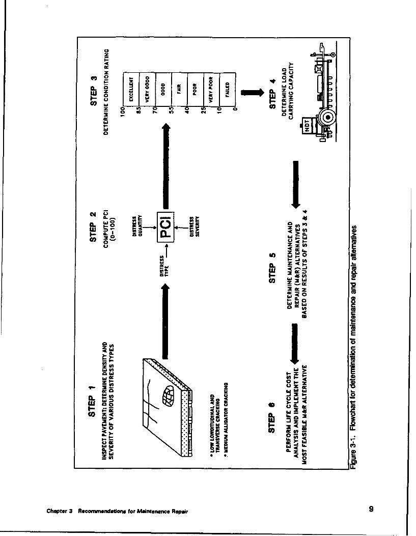
Steps I through 5 of the flow chart shown in Figure 3-1 were used indetermining the recommendations suggested in Table 3-2. The M&Ralternatives suggested for the existing surfaces were selected from those listedfor various distresses in AC pavements shown in Table 3-3. In manyinstances, the performance of a specific alternative depends upon thegeographical location and expertise of local contractors. Therefore, it issuggested that the local DPW personnel review all recommendations. Localcosts for the approved alternatives can then be used with the Micro Paverprogram to obtain a reasonable cost estimate. All overlay, repair, orconstruction should be in accordance with ETL 1110-3-393 (Headquarters,Department of the Army, 1988) which required PCC at runway ends and forthe primary taxiway and parking apron systems. The features in Table 3-2marked with " s" require a PCC surface if reconstructed.
The PCI was developed to determine maintenance and repair needs. If thePCI is low, maintenance or repair is needed to increase the PCI. If the PCI islow and the PCN is greater than the ACN, localized maintenance or repairwill generally be an acceptable solution. Although these maintenanceactivities and repairs will improve the PCI to acceptable levels, this does notmean that this is the most cost-effective alternative. An overlay or otheroverall improvement may be more cost-effective than considerable localizedmaintenance or repairs. Certainly, if the current PCI is less than 25, overallimprovements should be investigated. When an overlay is recommended, themaintenance recommended is that needed to keep the pavement serviceableuntil the overlay is applied. Although these recommendations will raise thePCI, this does not insure that the improved PCI will remain above theminimum levels for the analysis period. The PCN and the ACN weredeveloped to determine the capability of an airfield pavement to safely supportdifferent aircraft. If an improvement is needed to increase the PCN to theACN and only repairs to improve the PCI are applied, the pavement willprobably deteriorate quite rapidly under traffic. If the PCN is lower than theACN, the pavement needs an improvement to increase the load carryingcapacity so that the PCN will be greater than or equal to the ACN. In somecases, the PCI may be high while the PCN is lower than the ACN. In thiscase, the pavement needs an improvement to increase the load carryingcapacity of the pavement.
8 Chapter 3 Recommendatione for Maintenance Repair
z
400
Isu Z I 3' L 0 II z-~me 0 ~ &n ~ ' n 0 e
a:a
WF00-
C#A V
CLoLU W (In I
A. >aso420 W 9A
Wm
1.0 IL
E1 W4w
IL
z w
00 z
LU SO
a-aaed >~
22
Chptr Reomedato be aneaneRpi

Table 3-1Airfield Pavement Evalaution General Summary'
Recommendations
Pavement DoFeature PCI ACNIPCN2 Nothing Maintenance Repair Construction
R1E 99 0.7 X
R2E 96 0.7 X
R3E 100 0.7 X
TIE 98 0.7 X
AlE 77 0.9 X
Work is categorized for preliminary planning purposes only. Classification of work foradrinistrative approval is an installation responsibility. Policy guidance for airfield pave-merts is provided in AR 420-72. In general, if the pavement real property facility is in afailed or failing condition, structural improvements to accommodate normal growth andevolution of missions and equipment are properly classified as repair work. The followingtypes of work are properly classified as construction: strengthening of a pavement toaccommodate a new mission, extension or widening of the pavement, or complete replace-ment of the real property facility. Refer to AR 420-72 for specific guidance.2 Determined for design aircraft during the non-frost period.
10 Chapter 3 Recommendations for Maintenance Repair

40 ad a
* 5 S 0
0 0 a
C4 C - I
C £ c C
a 00
.C r
*1 C C S
C .0 .0 0D.1 0
C fC : £ .C
Mc U UCa ~
'E O we
IL 0 0 0
.2 100
0'0 0 C4 m LE d0, at L163
35 I- I EU L U !2
* U. ~ P
Chpe 3 eovedtosfrMitnneRpi

z x k :k
:3; 4 z _ x
x x x x
J -
-0_ 1 -j J C. -
:31 '4510,
* 31 3_1 -1 1 _ 41 J
ro 4 _ _ - - __ -- -
12~~~z Chpe UeomnainsfrMitnneRpi

4 Conclusions
General
The results of the evaluation in Table 3-2 were determined based onrepresentative conditions at the time of testing. It should be noted that theCBR values, based on the results of the DCP testing, determined for thevarious pavement layers can deviate throughout the year. Therefore, it isrecommended that before specific structural improvements are programmed, athorough pavement analysis and design be completed to select the most cost-effective improvement technique. To be in accordance with ETL 1110-3-393(Headquarters, Departemnt of the Army, 1988) all of the features at BAAFare required to have a PCC surface if structural improvements are planned.
The maintenance and rehabilitation alternatives discussed in Chapter 3 andsummarized in Table 3-2 should be performed as soon as possible to retain thefull benefit of the structural capacity of the existing pavement. Themaintenance and repair alternatives suggested for the existing surfaces wereselected from those listed for the various distresses shown in Table 3-3. Inmany instances the performance of a specific alternative is dependent uponlocal conditions and contractors.
The operational ACN for the pavement facilities at BAAF is 24/F/A/W/T.
Structural Capacity and Condition Ratings
Runway 09-27
All features of Runway 09-27 should withstand the 20-year projected day-to-day operations. At a minimum, routine maintenance should be performedon all the pavement features to insure maximum performance.
The PCN for runway 09-27 is 36/F/A/W/T. The general condition ratingof Runway 09-27 is excellent.
Chapter 4 Conclusions 13

Taxiway
The taxiway should, with routine maintenance, withstand the 20-yearprojected day-to-day operations.
The PCN for the taxiway is 36/F/A/W/T. The general condition rating ofthe taxiway is excellent.
Apron
The Apron should, with routine maintenance, withstand the 20-yearprojected day-to-day operations.
The PCN for the apron is 27/F/A/W/T. The general condition rating ofthe apron is very good.
14 Chapter 4 Conclusions

References
Headquarters, Department of the Army.(I988). "Air TrafficControl, Airspace, Airfields, Flight Activities,and NavigationalAids" Army Regulation AR 95-2,Washington,DC.
__________(1988). -Guidance to be Used for the Types ofSurfaced Areas," Engineering Technical Letter ETL 1110-3-393,U.S. Army Corps of Engineers, Washington,DC.
________.(1991). *Enginering and Design AircraftCharacteristics for Airfield-Heliport Design and Evaluation,"Engineering Technical Letter ETL 1110-3-394, U.S. Army Corpsof Engineers, Washington,DC.
__________.(1991). "Surfaced Areas,Bridges,Railroad Track andAssociated Appurtenances,"Army Regulation AR 420-72Washington,DC.
Headquarters, Departments of the Army and the Air Force. (1988)." Airfield Pavement Evaluation Concepts," Technical ManualTM 5-826-1/AFM 88-24,Chap. 1, Washington,DC.
__________.(1988). "Rigid Pavements for Airfields," TechnicalManual TM 5-825-3IAFM 88-6,Chap.3, Washington,DC.
__________.(1989). "Procedures for U.S. Army and U.S. Air ForceAirfield Pavement Condition Surveys," Technical ManualTM 5-826-6/AFR 93-5, Washington,DC.
___________.(1990). "Airfield Flexible Pavement Evaluation,"Techincal Manual TM 5-826-2/AFM 88-24,Chap. 2, Washington,DC.
__________.(1993). "Standard Practice for Sealing Joints and Cracks inRigid and Flexible Pavements," Technical ManualTM 5-822-I 1/AFP 88-6,Chap.7, Washington,DC.
Headquarters,Departments of the Navy, the Army, and the Air Force.(1978). "Flexible Pavement Design for Airfields," Design ManualDM21.3/TM 5-825.2/AFM 88-6 Chap.2, Washington,DC.
References 15

Webster,Steve L., Grau,Richard H., Williams,Thomas P., (1992)."Description and Application of Duel Mass Dynamic ConePenetrometer," Instruction Report GL-92-3, U.S. Army EngineerWaterways Experiment Station, Vicksburg,MS.
16 References
Appendix ABackground Data
Description of the Airfield
BAAF is located on Pohakuloa Training Area, Hawaii, approximately 48km (30 mi) northwest of Hilo, HI. In February 1994, the airfield consisted ofone AC runway with a perpendicular AC taxiway and an AC apron.
A layout of the airfield pavements is shown in Figure Al. Runway 09-27is 27 m (90 ft) wide and 1127 m (3,700 ft) long. The airfield is located nearthe center of the island of Hawaii. The elevation of the airfield is at 1886 m(6189 ft) mean sea level.
Previous Reports
Pertinent data for this airfield were extracted from a previous evaluationreport (U.S. Army Engineer Division, Pacific Ocean, "Pavement Evaluationfor Bradshaw Army Airfield, Pohakuloa Training Area, Hawaii," January1981, Fort Shafter, Hawaii) for use in this report.
Design and Construction History
The original runway pavement at BAAF is believed to have beenconstructed in the early 1950's. The taxiway and apron were constructed in1958. Accurate construction records of the initial construction are notavailable. In 1965, extensions to the apron were constructed. In 1979 theairfield was upgraded to support the operation of C-130 aircraft. Theupgrading included the construction of an asphalt concrete inlay for the keelsection of the runway, the addition of turnarounds to both ends of the runway,and a complete reconstruction of the taxiway. Those pavements not newly orreconstructed received a 4 cm (1.5 in) asphalt concrete overlay. Table AIpresents the history of the major construction activities at BAAF. Table A2contains a summary of the physical property data of the various features. The
Appendix A Background Data Al

locations of the various pavement features can be determined from Figure A2.
Figure A3 shows typical foundation and pavement sections.
The major construction projects as BAAF are summarized as follows:
a. 1950-1955 construction. The only facility constructed during thisperiod was runway 09-27.
b. 1958 construction. The taxiway and apron were constructed.
c. 1965 construction. Extensions to the apron were constructed to the eastand west.
d. 1979 construction and reconstruction. A 8 cm (3 in) AC overlay wasconstructed in the keel section (center 12 m (40 ft)) of the runway, anda 4 cm (1.5 in) AC overlay was constructed on edges of the runway.Turnarounds with 8 cm (3 in) of AC surface were constructed at eachend of the runway. The taxiway was reconstructed with a 8 cm (3 in)AC surface. The center portion of the apron recieved a 8 cm (3 in)overlay, the east and west ends of the apron received 4 cm (1.5 in ) ACoverlays.
Traffic History
Airfield activity records were obtained from base operations personnel atBAAF for the 1993 calendar year. The 1993 records were used to project thetraffic the airfield would be expected to support for the next 20 years. Fromthe data provided by the operations personnel, the 20 year day-to-dayoperations to be used for evaluation was determined to be 15,000 passes of a70,300 Kg (155-kip) C-130.
A2 Appendix A Background Data

9z
zz
I-
ccI
I Cn
0
Appwx A ed~ond Dta A

I I� NI
' �
It Ida � !e�a
AF�
ma'
WE
4-00,C0
4-aU
Sd 0*0C0
C0
4-0U
-
4-C
*00)
0El
4-06)
4-C
4)E0)0
a-
h..
5-0 �
A4 Appenix A Background Dais
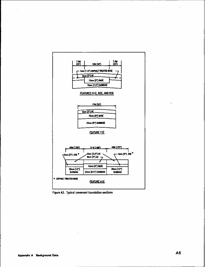
'(2'51 12U(40, 1 (251
4-m (,(1.51 AST M.ATED BASE
15M(r) UK19C (7.5:1 suMeSE
FEATURES RIE. R2E. AND RXE
15 (r) BSEm
FEATURE TI E
40M ON(0) 51M OW() 48Q (57)
5an (2-) AYl* (3.5"IAC SceD (T') All• 12") m* ,,.,,m (3.-•) AC .- •1"1'*
I.'-- -- 5C I s(r)n. UK/ C •(•2") 30an (12-)
, ASPNALT TREATED BASE
Figure A3. Typical pavement foundation sections
Appendix A Background Data A5

Table AlConstruction History
Pavement
Pavement FaooPityavme(Feature) Thickness. am (in.) Type Date
Runway 09-27 4 (1.5) ATB2 1950-55(R1E. R2E, R3E) 8 (3) AC' 1979
Taxiway(T1 E) 4 (1.5) ATB2 1958
843) AC 1979 (ATSremoved)
Apron(ALE) 5 (2) ATB2 1958
8 (3) AC 1979 (ATBremoved)
Apron Extensions 6 (2.25) AC 1965(A2E, A3E) 4(1.5) AC1 1979
Overlay Pavement.2 Asphalt Treated Base.
A6 Appendix A Background Data

doi
t t
a a4C 2 t. a
f4. . . .4 W
A7Appendix A Background Date
uno-u nu numnn nn-n anUi -

Appendix BTests and Results
Tests Conducted
The pavements were evaluated based on the results from dynamic conepenetrometer (DCP) tests. The test procedures and results are discussedbelow.
Dynamic Cone Penetrometer Tests
A DCP soil test device was used to obtain subsurface soil data atrepresentative locations. The DCP is a steel cone attached to the end of ametal rod on the other end of which is located an 8 kg (17.6-Ib) sliding drop-hammer. For this investigation a small hole was cored through the ACmaterial. The cone of the DCP was then placed on top or near the top of thebase and the hammer was then dropped repeatedly to drive the cone throughthe underlying pavement layers. The material resistance to penetration wasrecorded in terms of millimeters penetrated per hammer blow. CaliforniaBearing Ratio (CBR) was then determined based on a correlation andprocedure recommended in (Webster, Grau, and Williams 1992). DCP testswere performed at select locations of BAAF as shown in Figure B I. Theresults of the DCP tests are best illustrated on a plot of CBR versus depth foreach test location. Figures B2 through B9 show these data for the tests per-formed on the facilities. It should be noted that when analyzing the DCPdata, the regression equation used to backcalculate the CBR may indicate aCBR value greater than 100 percent. A CBR of 100 percent is considered themaximum (see DM21.3/TM 5-825.2/AFM 88-6 Chap.2). Any backcalculatedCBR greater than 100 percent was plotted as 100 percent in Figures B2through B9 and considered 100 percent for evaluation purposes.
Appendix B Tests and Results B1

2
92
* f.
0
0
0
-
4-
* 0U)
04-0U0
.4-U)0)
4-.
00 c�)
a)I- L.9-00)zir
B2 Appendx B Tess u�d R.sti�

Feature R2ERunway 09-27, Station 5+00
CBR. percent10 100
0.0 0
105.0
2010.0
30
d 15.0 E40~
~20.0 060
25.0 Note: Test was c it off because DCP
could not penet 2e base material. 7030.0 8
35.0 90
Figure B2. DCP results, Runway 09-27, Station 5 + 00
Feature R2ERunway 09-27, Station 32+00
CBR, percent
1 10 100
0.0 0
5.0 10
2010.0
30
15.0 4 0 E
25.0 so
Note: Test was c t off because DCP 7030.0 could not penev ate base material.
35.0 90
40.0 100
Figure B3. DCP results, Runway 09-27, Station 32 + 00
Appendix B Tests and Results 83

Feature TIETaxiway, Station 1+00
CSR, percent10 100
0.0 .. . .. 0
5.0 10
2010.0
30
15.0 40 E
120.0 50
25.0 6o
7030.0
8035.0 90
40.0 100
Figure B4. DCP results, Taxiway, Station 1 + 00
Feature AlEApron, Test I
CBR, percent1 10 100
0.0 .. 0
5.0 10
2010.0
30
15.0
S20 .0 so
25.0
7030.0
80
35.0 90
40.0 100
Figure B5. DCP results, Apron, Test 1
B4 Appendix B Tests and Results

Feature AlEApron, Test 2
CBR. percent1 10 100
0.0 0
5.0 10
2010.0
3015.0 40
S20.0 50
S25.0 so
7030.0
80
35.0 90
40.0 100
Figure B6. DCP results, Taxiway, Test 2
Overrun09 End, Test I
CUR, percent10 100
0.0 0...... 0
5.0 10
2010.0
30
_d 15.0 40 E
CL~ soIS20.0 iso,60
25.0 Note: Test was ut off
due to incomming aircraft. 7030.0 80
35.0 90
Figure B7. DCP results, 09 End Overrun, Test 1
Appendix B Tests end Results B5

Overrun09 End, Test 2
CBR, percent
10 100
0.0 0
5.0 10
2010.0
30
15.0 40
20.0 50
25.0 60
30.0 70
8o35.0 90
40.0 100
Figure B8. DCP results, 09 End Overrun, Test 2
Overrun27 End, Test I
COR, percent
1 10 1000.0 0......0
5.0 10
2010.0
30
15.0d 40 E•20.0 50Q.
IE 25.0 6o a70
30.08o
35.0 90
40.0 100
Figure 9. DCP results, 27 End Overrun
B6 Appendix B Tests and Results

Appendix CPavement Condition Survey andResults
Pavement Condition Survey
A pavement condition survey is a visual inspection of the airfieldpavements to determine the present surface condition. The condition surveyconsists of inspecting the pavement surface for the various types of distresses,determining the severity of each distress, and measuring the quantity of eachdistress. The condition survey provides estimated quantities of each distresstype and severity from which the pavement condition index (PCI) for eachfeature can be determined. The PCI is a numerical indicator based on a scalefrom 0 to 100 and is determined by measuring pavement surface distress thatreflects the surface condition of the pavement. Pavement condition ratings(from excellent to failed) are assigned to different levels of PCI values. Theseratings and their respective PCI value definitions are shown in Figure C1.The distress types, distress severities, methods of survey, and PCI calculationare described in TM 5-826-6/AFR 93-5 (Headquarters, Departments of theArmy and the Air Force 1989).
Condition survey procedure
The PCI and estimated distress quantities are determined for each feature.The information is based on inspection of a selected number of sample units.Sample units are subdivisions of a feature used exclusively to facilitate theinspection process and reduce the effort needed to determine distress quantitiesand the PCI. Each feature was divided into sample units. The sample unitsfor the AC pavement features were approximately 465 sq m (5000 sq ft). Thestatistical sampling technique was used to determine the number of sampleunits to be inspected to provide a 95 percent confidence level. Sample unitswere chosen along the center line of the runway and taxiway and were chosenrandomly on the apron. The stationing and direction of survey are shown inFigure BI. The locations of the sample units on the apron are shown inFigure C2. After the sample units were inspected, the mean PCI of allsample units within a feature was calculated and the feature was rated as to itscondition: excellent, very good, good, fair, poor, very poor, and failed.
Appendix C Pavement Condition Survey and Results C 1
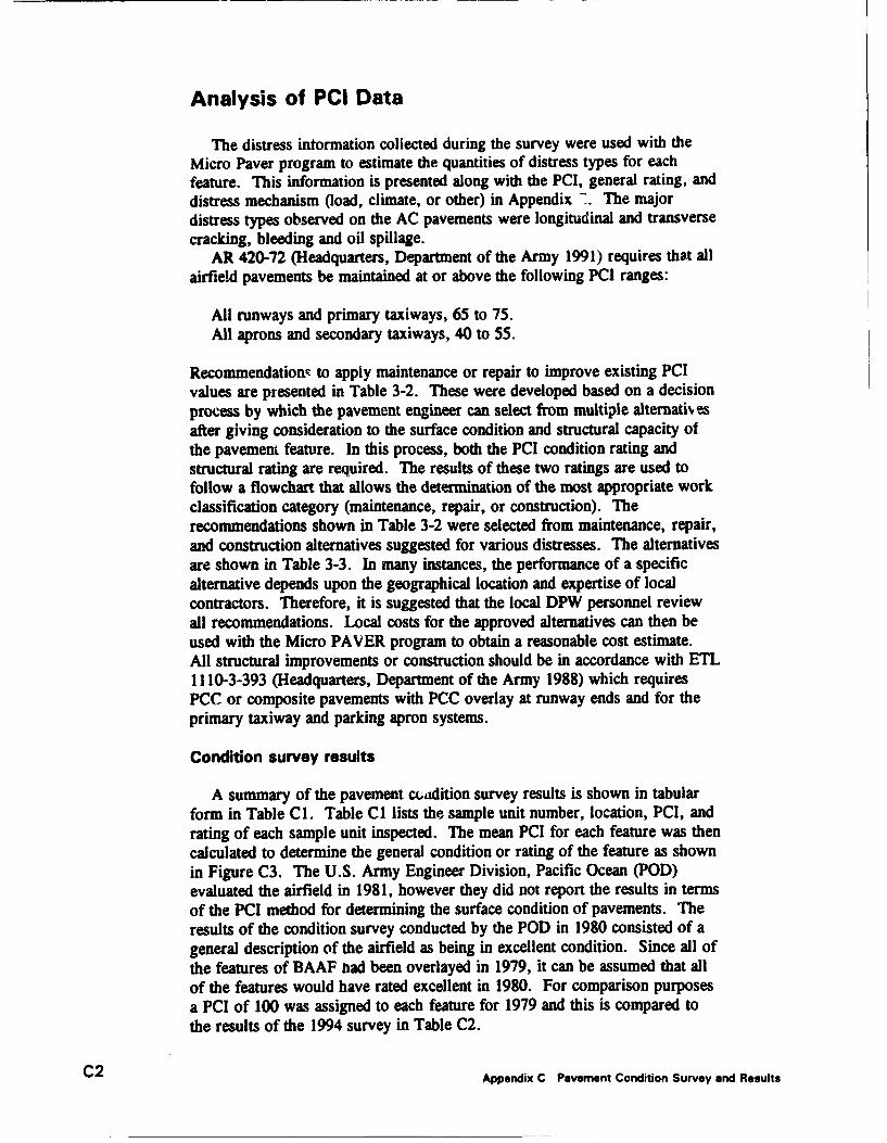
Analysis of PCI Data
The distress information collected during the survey were used with theMicro Paver program to estimate the quantities of distress types for eachfeature. This information is presented along with the PCI, general rating, anddistress mechanism (load, climate, or other) in Appendix 7. The majordistress types observed on the AC pavements were longitudinal and transversecracking, bleeding and oil spillage.
AR 420-72 (Headquarters, Department of the Army 1991) requires that allairfield pavements be maintained at or above the following PCI ranges:
All runways and primary taxiways, 65 to 75.All aprons and secondary taxiways, 40 to 55.
Recommendationv to apply maintenance or repair to improve existing PCIvalues are presented in Table 3-2. These were developed based on a decisionprocess by which the pavement engineer can select from multiple alternati-vesafter giving consideration to the surface condition and structural capacity ofthe pavement feature. In this process, both the PCI condition rating andstructural rating are required. The results of these two ratings are used tofollow a flowchart that allows the determination of the most appropriate workclassification category (maintenance, repair, or construction). Therecommendations shown in Table 3-2 were selected from maintenance, repair,
and construction alternatives suggested for various distresses. The alternativesare shown in Table 3-3. In many instances, the performance of a specificalternative depends upon the geographical location and expertise of localcontractors. Therefore, it is suggested that the local DPW personnel reviewall recommendations. Local costs for the approved alternatives can then beused with the Micro PAVER program to obtain a reasonable cost estimate.All structural improvements or construction should be in accordance with ETL1110-3-393 (Headquarters, Department of the Army 1988) which requiresPCC or composite pavements with PCC overlay at runway ends and for theprimary taxiway and parking apron systems.
Condition survey results
A summary of the pavement cuadition survey results is shown in tabular
form in Table CI. Table CI lists the sample unit number, location, PCI, andrating of each sample unit inspected. The mean PCI for each feature was thencalculated to determine the general condition or rating of the feature as shownin Figure C3. The U.S. Army Engineer Division, Pacific Ocean (POD)evaluated the airfield in 1981, however they did not report the results in termsof the PCI method for determining the surface condition of pavements. Theresults of the condition survey conducted by the POD in 1980 consisted of ageneral description of the airfield as being in excellent condition. Since all ofthe features of BAAF had been overlayed in 1979, it can be assumed that allof the features would have rated excellent in 1980. For comparison purposesa PCI of 100 was assigned to each feature for 1979 and this is compared tothe results of the 1994 survey in Table C2.
C2 Appendix C Pavement Condition Survey and Results

PAVEMENT COND!TION PAVEMENT CONDITION
INDEX (PCI) RAIING
100 4
** EXCELLENT
85VERY GOOD
70 77-/7 GOOD
55
FAIR
40POOR
25VERY POOR
10I - I FAILED0 --- _ _ . _ _ _ _
Figure Cl. Scale for pavement condition rating
Appendix C Pavement Condition Survey and Results C3

I (.Cot ) "EitI
(00
Figure C2. Sample unit layout, Apron
C4 Appendix C Pavement Condition Survey and Results

!1 0+ , + z j
+ Wl )+, +j 0
++
+
+
+
+
4C
4E
4t
A-4
4~PIZ
Amenix CPavrnen Coditin Smay nd esuls C

Table C1Pavement Condition Survey Results
Station Overall
Feature Unit From To PCI Rating PCI Rating
RIE 1 0+00 1+00 98 Excellent2 1+00 2+00 100 Excellent 99 Excellent3 2+00 3+00 100 Excellent
R2E 5 4+00 5+00 97 Excellent9 8+00 9+00 96 Excellent13 12+00 13+00 100 Excellent17 16+00 17+00 95 Excellent 96 Excellent21 20+00 21 +00 96 Excellent27 26+00 27+00 95 Excellent31 30+00 31 +00 95 Excellent34 33+00 34+00 96 Excellent
R3E 35 34+00 35+00 100 Excellent36 35+00 36+00 100 Excellent 100 Excellent37 36+00 37+00 100 Excellent
T1E 1 0+00 1+00 97 Excellent 98 Excellent2 1+00 2+00 100 Excellent
AlE 1 85 Very Good3 81 Very Good5 84 Very Good 77 Very7 100 Excellent Good91 41 Fair11 76 Very Good13 76 Very Good
Sample unit number 9 of feature Al E contained a great deal of bleeding which caused it to
have a much lower PCI rating than the other sample units surveyed in the feature.
C6 Appendix C Pavement Condition Survey and Results

Table C21979 PCI Compared with 1994 PCI
1979 1994 Change 1987 1993Feature' PCI PCi in PCI Rating Rating
laessumed)
R 1E 100 99 -1 Excellent Excellent
R2E 100 96 -4 Excellent Excellent
R3F 100 100 0 Excellent Excellent
TI L 100 98 -2 Excellent Excellent
ME 100 77 -23 Excellent Very Good
'All pavement fecatures are AC.
Appendix C Pavement Condition Survey and Results C7

Appendix DStructural Analysis
General
The projected performance of the airfield pavement facilities was analyzedfor a 20-year analysis period. The traffic for this period was based on theinformation provided by the installation. The critical aircraft operating on thepavements at BAAF was determined to be the 70,300 kg (155-kip) C-130aircraft. The airfield was evaluated for 15,000 operations of the criticalaircraft.
The operational ACN values were determined based on the critical aircraft;the 70,300 kg (IS5-kip) C-130 on the AC pavements. The results showingthe ACN values for each pavement type and subgrade strength, are shown inTable DI.
During wartime, many aircraft are allowed to carry heavier loads thanduring peacetime. This means that the aircraft would have a higher ACNbecause of the higher loading and would cause more damage than inpeacetime. This would reduce the life of the pavement. A mobilization ACNcan be determined from the appropriate ACN-PCN curve presented in thedraft ETL 1110-3-394 (Headquarters, Department of the Army 1991). TheACN-PCN curve for a C-130 on both flexible and rigid pavements are shownin Figure Dl. During contingency planning, there is often the need todetermine the largest possible aircraft that can safely land on the airfield.Generally the length of the runway controls this. Minimum take-off distancesfor maximum take-off weights of aircraft are also given in ETL 1110-3-394(Headquarters, Department of the Army 1991). Once the aircraft is known,the ACN of that aircraft can be determined from the ACN-PCN curve andthen the effect of the higher loads on the airfield can be determined from theACN/PCN ratio and pavement life utilized or passes till failure curves.Specific aircraft mobilization traffic requirements are contained in classifiedmobilization plans and are not included in this report.
Appendix D Structural Analysis D1

ACN-PCN Method of Reporting PavementStructural Condition
The ACN-PCN method is used to provide a means of reporting the struc-tural evaluation of a pavement. This procedure is a standardized InternationalCivil Aviation Organization (ICAO) method. The ACN is used to express theeffect of individual aircraft on different pavements by a single unique numberwhich varies according to pavement type and subgrade strength withoutspecifying a particular pavement thickness. Conversely, the PCN of apavement can be expressed by a single unique number without specifying aparticular aircraft. The ACN and PCN values are defined as follows:
a. ACN - A number which expresses the relative structural effect of anaircraft on different pavement types for specified standard subgradestrengths in terms of a standard single-wheel load.
b. PCN - A number which expresses the relative load-carrying capacity ofa pavement for a given pavement life in terms of a standard single-wheel load.
The ACN-PCN method is structured so that the structural evaluation of apavement for particular aircraft can be accomplished by using the ratio of theaircraft ACN to the pavement PCN. For a given pavement life and a givennumber of operations fo" a particular aircraft there is a relationship betweenthe ACN/PCN ratio and the percent of pavement life used by the appliedtraffic. For a given ACNIPCN ratio a relationship exists for the number ofoperations that will produce failure of the pavement. This relationshipprovides a method for evaluating a pavement for allowable load depending onacceptable degree of damage to the pavement or an allowable number ofoperations of a particular aircraft to cause failure of a pavement. For aircrafthaving an ACN equal to the PCN the predicted failure of the pavement wouldequal the design life of the pavement. Aircraft having ACN's higher than thepavement PCN would overload the pavement and decrease the life of thepavement. Likewise if the ACN of the operational aircraft is less than thepavement PCN, the structural life of the pavement would be greater than thedesign life. If the operational ACN is greater than the pavement PCN and adecrease in pavement life is not acceptable, then structural improvement of thepavement is required to bring the pavement PCN up to or greater than theoperational ACN.
Determination of CBR for Analysis
DCP tests were run at several locations at BAAF. Figures B2 through B9show a plot of the CBR values versus depth obtained from the DCP tests.From Figures B2 through B9, it can be observed that the DCP calculated CBRis above the design CBR for each pavement feature with the exception of oneof the DCP tests in feature AlE. The design CBR for each pavement layer is
D2 Appendix D Structural Analyse

80 percent for base course, 50 percent for subbase course, and 15 percent forhigh strength subgrades. Table D2 shows the DCP measured CBR and designCBR of each pavement layer for each feature evaluated. In order to provide areasonably conservative evaluation, and be in accordance with the maximumvalues recommended in DM 21.3/TM 5-825.2/AFM 88-6 Chap.2, the CBRused for evaluation was the lessor of the DCP measured CBR or the designCBR. Features RIE, R2E, R3E and TIE were evaluated based on the designCBR. Feature AlE was evaluated based on the DCP measured CBR-
PCN Analysis
The PCN for each pavement feature was determined in accordance withTM 5-826-5/AFP 88-24 (Headquarters, Departments of the Army and theAir Force 1993). Using the design aircraft and traffic levels for normaloperations the PCN was determined for each pavement feature. The PCN isdetermined using the allowable gross aircraft load and the subgrade strengthcategory determined from the CBR. A typical ACN-PCN curve is shown inFigure Dl. Table D3 presents a summary of the evaluation of each pavementfeature in terms of allowable gross aircraft loadings, PCN, and overlaysrequired to bring the PCN up to the required PCN (ACN of the designaircraft). The APEC presented in Figure 2-1 shows a layout of the airfieldpavements and corresponding PCN for each facility.
Because all pavement features (with the exception of the overruns) had acalculated PCN greater than the required ACN, an analysis was not necessaryto determine additional sg requirements to increase the PCN toequal the current ACN. If the PCN is less than the ACN, an increase instrength requirement is determined and reported as an overlay thickness. Anoverlay thickness required to provide a PCN equal to the ACN was reportedfor the overruns in Table D3. Although the increase in strength is presented asan overlay thickness, several other approaches could be used to increase thestrength. A detailed analysis is required to select and design the most cost-effective repair or improvement alternative. It should be noted that minimumoverlay requirements, if necessary, would be indicated in Table D3, thefollowing minimum thicknesses are recommended:
a. 5 cm (2-in.)-thick minimum AC overlay over AC pavements.
b. 10 cm (4-in.)-thick minimum AC overlay over PCC pavements.
c. 15 cm (6-in.)-thick minimum PCC partially or nonbonded overlay.
d. 5 cm (2-in.)-thick minimum PCC fully bonded overlay over PCCpavements.
These minimum overlay requirements are required to control the degree ofcracking which will occur in the base pavement (existing pavement) due to theapplication of the design traffic. If any feature required structural
Appencx D Structural Analysis D3
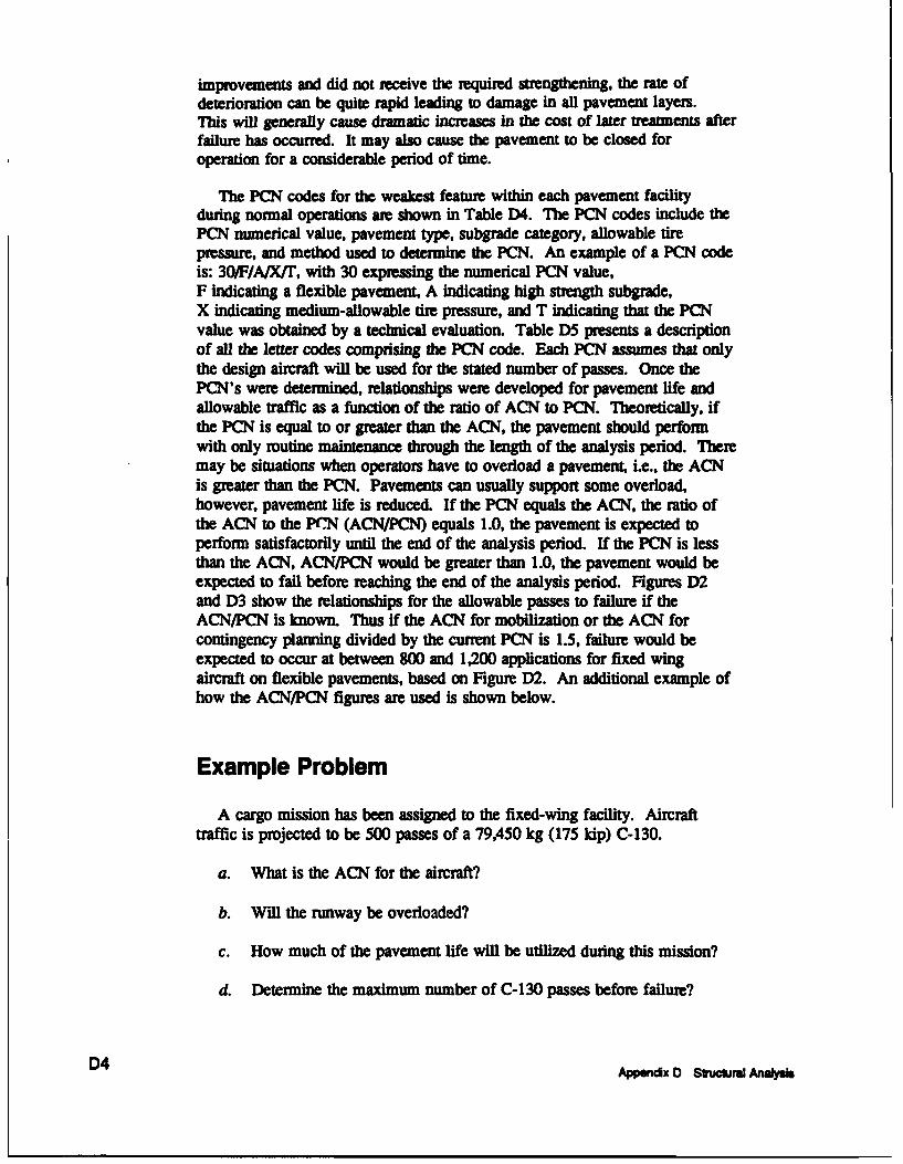
improvements and did not receive the required strengthening, the rate ofdeterioration can be quite rapid leading to damage in all pavement layers.This will generally cause dramatic increases in the cost of later treatments afterfailure has occurred. It may also cause the pavement to be closed foroperation for a considerable period of time.
The PCN codes for the weakest feature within each pavement facilityduring normal operations are shown in Table D)4. The PCN codes include thePCN numerical value, pavement type, subgrade category, allowable tirepressure, and method used to determine the PCN. An example of a PCN codeis: 30/F/A/X/Y, with 30 expressing the numerical PCN value,F indicating a flexible pavement, A indicating high strength subgrade,X indicating medium-allowable tire pressure, and T indicating that the PCNvalue was obtained by a technical evaluation. Table D5 presents a descriptionof all the letter codes comprising the PCN code. Each PCN assumes that onlythe design aircraft will be used for the stated number of passes. Once thePCN's were determined, relationships were developed for pavement life andallowable traffic as a function of the ratio of ACN to PCN. Theoretically, ifthe PCN is equal to or greater than the ACN, the pavement should performwith only routine maintenance through the length of the analysis period. Theremay be situations when operators have to overload a pavement, i.e., the ACNis greater than the PCN. Pavements can usually support some overload,however, pavement life is reduced. If the PCN equals the ACN, the ratio ofthe ACN to the PrN (ACN/PCN) equals 1.0, the pavement is expected toperform satisfactorily until the end of the analysis period. If the PCN is lessthan the ACN, ACN/PCN would be greater than 1.0, the pavement would beexpected to fail before reaching the end of the analysis period. Figures D2and D3 show the relationships for the allowable passes to failure if theACN/PCN is known. Thus if the ACN for mobilization or the ACN forcontingency planning divided by the current PCN is 1.5, failure would beexpected to occur at between 800 and 1,200 applications for fixed wingaircraft on flexible pavements, based on Figure D2. An additional example ofhow the ACM/PCN figures are used is shown below.
Example ProblemA cargo mission has been assigned to the fixed-wing facility. Aircraft
traffic is projected to be 500 passes of a 79,450 kg (175 kip) C-130.
a. What is the ACN for the aircraft?
b. Will the runway be overloaded?
c. How much of the pavement life will be utilized during this mission?
d. Determine the maximum number of C-130 passes before failure?
D4 Appenx D Sftra Analysr s
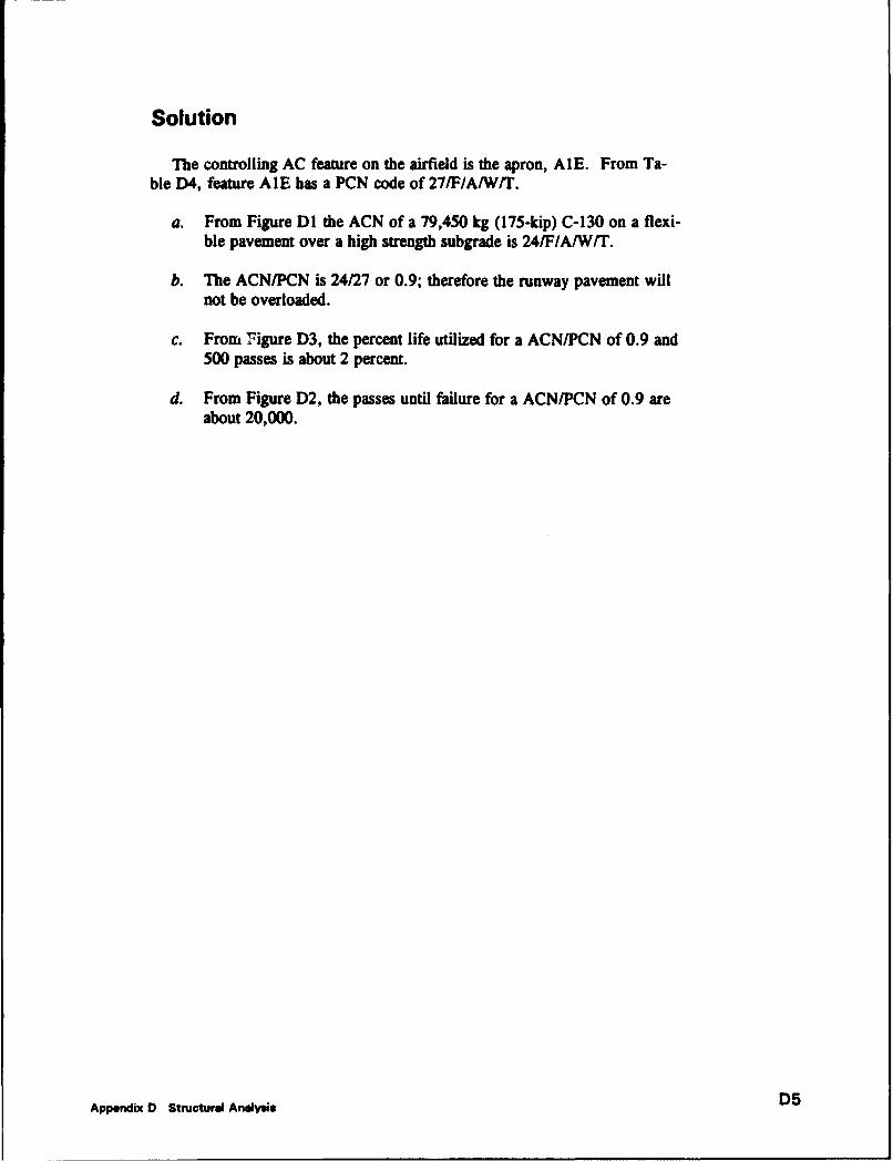
Solution
"The controlling AC feature on the airfield is the apron, AlE. From Ta-ble D4, feature AlE has a PCN code of 27/F/A/W/T.
a. From Figure DI the ACN of a 79,450 kg (175-kip) C-130 on a flexi-ble pavement over a high strength subgrade is 24/F/A/W/T.
b. The ACN/PCN is 24/27 or 0.9; therefore the runway pavement willnot be overloaded.
c. From Figure D3, the percent life utilized for a ACN/PCN of 0.9 and500 passes is about 2 percent.
d. From Figure D2, the passes until failure for a ACN/PCN of 0.9 areabout 20,000.
Appendix D Structural Analysis D5

45
40 Subgqrade Strengith •
A High CBR > 13 -00
35 BMedium CBR a 9 -13C Low CBR = 4 - 8 •" j / B
30 DUltra Low C1R<4
U25
U 20 .- 0
10
0
60 s0 100 120 140 160 10
Aircraft Gross Weight, (kips)Flexible Pavement
Subarade Strength
A High k > 400 pciB Medium k = 201 - 400 pci C
35 C Low k = 100 - 200 pciD Ultra Low k < 100 pci B
S30 0-.'0
20 ________-
10
60 80 100 120 140 160 180
Aircraft Gross Weight, (kips)Rigid Pavement
Figure D1. ACN curves for C-1 30 aircraft.
D6 Appendix D Structural Analysis

160 l g l , l " l l o
10
10'
C-10-4
10
10 0.. 5 . 5 35 4. .ACNPC
FiueD3 ecntlf uiie vru ANPN
Appendix 1 tutrl n sD

Table D1
Determination of ACN Values for Critical Aircraft
PCC Pavements
DeeignFixed-Wing Weight SubgradeAircraft kg (lib) Category' ACN or Required PCN
C-130 70.300 (155,000) A 27B 29C 32D 34
AC Pavements
DesignFixed-Wing Weight SubgradeAircraft kg Oib) Category' ACN or Required PCN
C-130 70.300 (155,000) A 249 28C 30
___________ ___________D 36
See Table D-4 for subgrade category.
DE Appendix 0 Structural Analysis

Table D.DCP measured CBR and Design CR tlor Each Pavement Layer
DCP Test Location CBR ipercent)
Base Layer Subbase Layer Subgrad. Layer
Runway, Station 53+00 100+ 100+
Runway, Station 32 + 00 100 + 1O00+ ---
Taxiway, Station 1 +00 85 85 50
Apron, Test 1 85 85 30
Apron, Test 2 60 35 35
09 End Overrun. Test 1 .....- 50
09 End Overrun, Test 2 50
27 End Overrun ..... 65
DESIGN 80 50 15
Appendix D Structural Analysis D9

bb-- --
510
It It lz lz
a~ -C------
0~oq0i u 0J 0i 0j .2 -- 4 C z1.
Cs 9s) AD4 -
o ~ ro
a 0.Co
CI C4 C4 +4 ( 4 I
w w Ir o C4bL -
D10 ~ ~ ~ ~ ~ ~ ~ - ApedxDSrcua oaUi

Table D4Summary of Pavement Classification Numbers
Conw o IpCN'.
Pavement Fecility Feature Normal Non-Frost
Runway RIE, R2E, R3E 36/F/A/W/T
Taxiway TIE 36/FiA/Wrr
Apron AIE 27/FIA/WA "
Overrun -12/F/A(W/T
Table D5 describes the components of the PCN code.
Appendix D Structural Analyis D11

Table D5PCN Five-Part Code
Method ofPCN Pavement Type Gubgrade Strength' Tire Pressure' PCN Determination
Numerical value R - rigid A W T - technical evaluationF - flexible B X U - using aircraft
C YD Z
Rexible Rigid PavementCategory Pavement CBR. % k. MN/m' (DSi/in)
A High Over 13 Over 108 (400)B Medium 8- 13 54-108 (201-400)C Low 4- 8 27-54 (100-200)D Ultralow < 4 < 27 (100)
f Code Catecy Tire Pressure. kPa (Doi)
W High No limitX Medium 1.0-1.5 (146-217)Y Low 0.5-1.0 (74-145)Z Ultralow 0-0.5 (0-73)
D12 Appendix D Structural Analysis

Appendix EMicro PAVER Output Summary
INSPECTION REPORTS. .. .. == =_== .. . . . = = == ==== -== = = = = = = = = = = = = = = = = = =
Network ID - WESBranch Name - APRON Section Length - 450.00 LFBranch Number - AIE Section Width - 140.00 LFSection Number - 1 Family - DEFAULT Section Area - 63000.00 SF----------------------------- =========================================-----------------
---------------------------------------------------------------------------------------Inspection Date: FEB/24/1994Riding Quality : Safety: Drainage Cond.:Shoulder Cond. : Overall Cond.: F.O.D.:
---------------------------------------------------------------------------------
PCI OF SECTION = 77 RATING = V. GOOD
TOTAL NUMBER OF SAMPLE UNITS = 13NUMBER OF RANDOM SAMPLE UNITS SURVEYED = 7NUMBER OF ADDITIONAL SAMPLE UNITS SURVEYED = 0RECOMMENDED MINIMUM OF 12 RANDOM SAMPLE UNITS TO BE SURVEYED.STANDARD DEVIATION OF PCI BETWEEN RANDOM UNITS SURVEYED = 18.0%
-*- EXTRAPOLATED DISTRESS QUANTITIES FOR SECTION ***
DISTRESS-TYPE SEVERITY QUANTITY DENSITY % DEDUCT VALUE42 BLEEDING N/A 1852.94 (SF) 2.94 15.648 L & T CR LOW 491.03 (LF) .78 4.548 L & T CR MEDIUM 932.03 (LF) 1.48 13.549 OIL SPILLAGE N/A 81.53 (SF) .13 2.1
*** PERCENT OF DEDUCT VALUES BASED ON DISTRESS MECHANISM *
LOAD RELATED DISTRESSES = .00 PERCENT DEDUCT VALUES.CLIMATE/DURABILITY RELATED DISTRESSES a 50.43 PERCENT DEDUCT VALUES.OTHER RELATED DISTRESSES = 49.57 PERCENT DEDUCT VALUES.
INSPECTION REPORT=... ============== -====-==-=====a======== ---- ========
Network ID - WESBranch Name - RUNWAY Section Length - 300.00 LFBranch Number - RIE Section Width - 90.00 LFSection Number - 1 Family - DEFAULT Section Area - 27000.00 SF
Inspection Date: FEB/24/1994Riding Quality • Safety: Drainage Cond.:Shoulder Cond. : Overall Cond.: F.O.D.:
Appendix E Micro Paver Output Summary El

INSPECTION REPORT
Network ID - WESBranch Name - RUNWAY Section Length - 300.00 LF
Branch Nmmber - RIE Section Width - 90.00 LFSection Number - 1 Family - DEFAULT Section Area - 27000.00 SF
Inspection Date: FEB/24/1994Riding Quality : Safety: Drainage Cond.:Shoulder Cond. Overall Cond.: F.O.D.:
PCI OF SECTION - 99 RATING - EXCELLENT
TOTAL NUMBER OF SAMPLE UNITS - 3NUMBER OF RANDOM SAMPLE UNITS SURVEYED - 3NUMBER OF ADDITIONAL SAMPLE UNITS SURVEYED - 0RECOMMEND EVERY SAMPLE UNIT BE SURVEYED.STANDARD DEVIATION OF PCI BETWEEN RANDOM UNITS SURVEYED " 1.0%
*** EXTRAPOLATED DISTRESS QUANTITIES FOR SECTION *
DISTRESS-TYPE SEVERITY QUANTITY DENSITY % DEDUCT VALUE45 DEPRESSION LOW 27.00 (SF) .10 .3
*** PERCENT OF DEDUCT VALUES BASED ON DISTRESS MECHANISM **
LOAD RELATED DISTRESSES - .00 PERCENT DEDUCT VALUES.CLIMATE/DURABILITY RELATED DISTRESSES - .00 PERCENT DEDUCT VALUES.OTHER RELATED DISTRESSES - 100.00 PERCENT DEDUCT VALUES.
INSPECTION REPORT
Network ID - WESBranch Name - RUNWAY Section Length - 3400.00 LFBranch Number - R2E Section Width - 90.00 LFSection Number - 1 Family - DEFAULT Section Area - 306000.00 SF
Inspection Date: FEB/24/1994Riding Quality : Safety: Drainage Cond.:Shoulder Cond. : Overall Cond.: F.O.D.:
PCI OF SECTION - 96 RATING - EXCELLENT
TOTAL NUMBER 7 SAMPLE UNITS - 34NUMBER OF RANDOM SAMPLE UNITS SURVEYED - U
NUMBER OF ADDITIONAL SAMPLE UNITS SURVEYED - 0RECOMIENDED MINIMVUM OF 5 RANDOM SAMPLE UNITS TO BE SURVEYED.STANDARD DEVIATION OF PCI BETWEEN RANDOM UNITS SURVEYED - 1.42
*** EXTRAPOLATED DISTRESS QUANTITIES FOR SECTION ***
DISTRESS-TYPE SEVERITY QUANTITY DENSITY 2 DEDUCT VALUE48 L & T CR LOW 1185.75 (IF) .39 3.8
E2 Appendix E icro Paver Output Summary

e** PERCENT OF DEDUCT VALUES BASED ON DISTRESS MECHANISM ***
LOAD RELATED DISTRESSES - .00 PERCENT DEDUCT VALUES.CLIMATE/DURABILITY RELATED DISTRESSES - 100.00 PERCENT DEDUCT VALUES.OTHER RELATED DISTRESSES - .00 PERCENT DEDUCT VALUES.
INSPECTION REPORT
Network ID - WESBranch Name - TAXIWAY Section Length - 250.00 LFBranch Number - TIE Section Width - 55.00 LFSection Number - 1 Family - DEFAULT Section Area - 13750.00 SF
Inspection Date: FEB/24/1994Riding Quality : Safety: Drainage Cond.:Shoulder Cond. : Overall Cond.: F.O.D.:
PCI OF SECTION - 98 RATING - EXCELLENT
TOTAL EWIBE OF SAMPLE UNITS - 2NUMBER OF RANDOM SAMPLE UNITS SURVEYED - 2NUKER OF ADDITIONAL SAMPLE UNITS SURVEYED - 0RECOMMEND EVERY SAMPLE UNIT BE SURVEYED.STANDARD DEVIATION OF PCI BETWEEN RANDOM UNITS SURVEYED - 2.21
* EXTRAPOLATED DISTRESS QUANTITIES FOR SECTION ***
DISTRESS-TYPE SEVERITY QUANTITY DENSITY 2 DEDUCT VALUE49 OIL SPILLAGE N/A 13.75 (SF) .10 2.0
*** PERCENT OF DEDUCT VALUES BASED ON DISTRESS MECHANISM ***
LOAD RELATED DISTRESSES - .00 PERCENT DEDUCT VALUES.CLIMATE/DVTRABILITY RELATED DISTRESSES - .00 PERCENT DEDUCT VALUES.OTHER RELATED DISTRESSES - 100.00 PERCENT DEDUCT VALUES.
Appendix E Niero Paver Output Summary E3

REPORT DOCUMENTATION PAGE OMB No. 01o,-oF
.4",n thWVni "'=den "0=a1.. .1 any:S. somitaec Of ffu,Infotowiomaton opatft oiw andKapit. 121 isffaqian==. nd-t t-- Office o!f a e aBudget9. Papetw •ArdutonP100 o070441K).**&%Watht•f DC 20.O13
1. AGENCY USE ONLY (Leave blank) 2. REPORT DATE 13. REPORT TYPE AND DATES COVEREDAugust 1994 Final report.TITLE AND SUBTITLE S. FUNDING NUMBERS
Airfield Pavement Evaluation, Bradshaw Army Airfield, MIPR No. E8793058414PJohakuloa Training Area, Hawaii
6. AUTHOnKS)William P. Grogan
7. PERFORMING ORGANIZATION NAME(S) AND ADORESSES) . PERFORMING ORGANIZATION
U.S. Army Engineer Waterways Experiment Station REPORT NUMBER
3909 Halls Ferry Road Miscellaneous PaperVicksburg, MS 39180-6199 GL-94-32
9. SPONSORING/MONITORING AGENCY NAME(S) AND ADORESS(ES) 10. SPONSORING/ MONITORING
Program Manager: U.S. Army Center for Public Works AGENCY REPORT NUMBER
(CECPW-ER), 7701 Telegraph RoadAlexandria, VA 22310-3860
11. SUPPLEMENTARY NOTES
12a. DISTRIBUTION/ AVAILABILITY STATEMENT 12b. DISTRIBUTION CODEDistribution is authorized to U.S. Government agencies only; testand evaluation; August 1994. Other requests for this documentshall be referred to Headquarters, U.S. Army Corps of Engineers(CEMP-ET), Washington, DC 20314-1000
13. ABSTRACT (Maximum 200 words)
An airfield pavement investigation was performed in February 1994 at Bradshaw Army Airfield,Pohakuloa Training Area, Hawaii, to develop information pertaining to the structural adequacy of the airfieldpavements for continued use under current mission and the upgrading of the pavements for mission changes.The pavement surface condition was evaluated using the pavement condition index (PCI) condition surveyprocedure, and a nondestructive evaluation procedure was used to determine the load-carrying capability ofthe pavements and overlay requirements for continued use of the pavements under current missions. Resultsof the evaluation are presented including: (a) a tabulation of the existing pavement features, (b) the results ofthe nondestructive tests performed using a dynamic cone penetrometer, (c) the PCI and condition rating of thesurface of each pavement feature, (d) a structural evaluation of each feature based on the projected 20-yearday-to-day traffic, (e) the pavement classification number for each pavement facility, and (f) maintenance andrepair recommendations based on the structural evaluation and condition survey.
14. SUBJECT TERMS 15. NUMBER OF PAGES
See reverse. 5216. PRICE CODE
17. SECURITY CLASSIFICATION 18. SECURITY CLASSIFICATION 19. SECURITY CLASSIFICATION 20. LIMITATION OF ABSTRACT
OF REPORT OF THIS PAGE OF ABSTRACT
UNCLASSIFIED UNCLASSIFIEDNSN 7540-01-280-5500 Standard Form 298 (Rev 2-89)
ft"cnred by ANSI Std Z19.18
291-102
14. (Concluded).
Aircraft/pavement classification numbersAirfield pavement evaluationBradshaw Army AirfieldOverlay requirementsPavement conditionPavement condition index