ad-a265 74(ato pg · agency use only ,'leaw w,'j;'w he pu) da (ai ... nsn 7540...
TRANSCRIPT

AD-A265 74(ATO PG
mnaw.,
~2222-4302 ar w tth'U -1"'
1. AGENCY USE ONLY ,'LeaW W,'J;'W HE Pu) DA (Ai
4 TITLE AND SUBTTLfE
AN INTEGRATED NAVIGATI1ON AP~PROACH1 FOR SHIPT'[ACK ITI~ L ': NIm('A'I; N A
M. E. Leblang, J. Kriegsman
7. PERFORMING ORGANZ7ATION NAME(S) AND ADURE:SSIESI 'r;.N. f.A:
Naval Command, Control and Ocean Surveillance Center (NCCOSC>RDT&E DivisionSan Diego, CA 92152-5001
9. SPONSORING/MONrTORING AGENCY NAME(S) AND ADDRESS(ES) *L. &f'0W,A)fi'U M')N1V).- N,
Naval Command, Control and Ocean Surveillance Center (N('COSC) AGENCY REP'OW Njvf'"-u-
RDT&E DivisionSan Diego, CA 92152 -5001 -
11. SUPPLEMENTARY NOTES
1 2a. OISTRIBLJTIONIAVAILABILIFIY STATEMENT 12t) DISTRII3UTION CODE
Approved for public release; distribution is unlimited.
13. ABSTRACT (Maximum 200 wcrds)
This paper describes a ship steering system that provides a means to accurately steer a ship along a prescribed tracksuch as a rhumb line, for indefinite distances. This is accomplished by applying frequcnt heading correct ions v-ia a t rack -keeping interface to the ship's autopilot, based on best present ship position data (BPP) and the prescribed track- Besztpres-ent position is obtained from an integrated navigation positioning system. The navigation positioning system computerprovides best present position as frequently as required, by integrating position data from land based Loran stat ions, satel-lite based GPS, an inertial navigation system and dead reckon aids. The prescribed track usually specified a,, a rhumb lineequation for survey applications generally may be described by any desired mathematical representation. The best presentposition and the mathematical representation of the track used to compute the off-track distance of the ship from the track.The off-track distance is used to develop proportional and integral heading corrections, which are applied to the autopilot byway of the track-keeping interface. The paper includes system performai ce i sults; of in-house simulations a nd shipboardoperation.
93- 13189
~~ (7~ Ij jj ~11!1J liJ I l j~Jill 11Published in 21st Joint Services Data Exchange for Guidance, Navigation and (Contr-ol, Oct 199)2 pp 35()- Th
14 SUBJECT TERMS NMIR Of PACGE_
command, control and communications,___________snn'array shipriders and factory support 6 FWCECODE
17 SECURIITY CLASSIqC(ATION 18 SECURITY CLASSS'OtCAT ION 19 !WCc H1"i' CLASSf ICATION i !V -MJA T-i ) OF, A- W , TRAA T
UNCLASSIFVIED UNCLASSI FIEl) UNCLASSIFI'El) SAMEF AS REPORT
NINN 7541) EI .281 WTif) Ir'anti '8itO I

I NCL SSI F E 1)
21a NAME OF RESPONSIBLE NDIVIDLUAL IM. Leblang (2153 441 -- 1659 (, '
NSN 7540 01-280 5500 tandA,•l foto 246 fBA(;Kl
UTN(,LASSI FIEf)

AN INTEGRATED NAVIGATION APPROACH
FOR SHIP TRACK CONTROL
by Martin Leblang and Jules Kriegsman
Naval Command, Control and Ocean Surveillance Center
RDT&E Division Detachment Warminster, PA
1. ABSTRACT
a This paper describes a ship steering system that provides a means to accurately steera ship along a presc-ibed track such as a rhumb line, for indefinite distances. This isaccomplished by applying frequent heading corrections via a track-keeping interface to theship' s autopilot, based on best present ship position data (BPP) and the prescribed track.Best present position is obtained from an integrated navigation positioning system. Thenavigation positioning sy-term computer provides best present position as frequently asrequired, by integrating position data from land based Loran stations, satellite based PS.an inertial navigation system and dead reckon aids. The prescribed track usually specifieaas a rhumb line equation for survey applications generally may be described by any desiredmathematical representation. The best present position and the mathematicalrepresentation of the track are used to compute the off-track distance of the ship from thetrack. The off-track distance is used to develop proportional and integral headingcorrections, which are applied to the autopilot by way of the track-'eepng interface. Thepaper includes system performance results of in-house simulations and shipboard operation.
2. INTRODUCTION
An integrated navigation approach provides high quality ship position informationbased on the best combination of available navigation data. The position data used inconjunction with the track-keeping algorithm described herein, is sufficient to guide a shipalong a prescribed track. Efficient acquisition of bathymetric, gravimetric and magneticdata is accomplished along prescribed rhurmb line tracks. The integrated navigation systemconsists of GPS and Loran-C receivers, an inertial navigator, electromagnetic and dopplerspeed logs, and a navigation computer to process and combine all of the available navigationdata into the Best Present Ship's Position (BPP). The integration of the inertial navigatorand dead reckon aids with GPS and Loran data, allows filtering of any high frequency noiseerrors of the GPS and Loran data.
Prior to the development of the approach described herein, course corrections forcross track drift were obtained by monitoring a track plot and calling corrections u? to thehelmsman who set the change into the autopilot. The automated approach to ships trackcontrol, uses the high quality BPP to determine virtually instantaneous cross track errorsto drive a proportional plus integral (PI) controller in the navigation computer to deriveheading corrections which are applied to the autopilot to maintain the ship on track.

3. TRACK GUIDANCE CRITERIA
A track specification defined as a point on the track and the angle of the track withrespect to north (desired ground track) are entered into the navigation. computer forapplication to the track control algorithm. The ship is initially manually steered toward thedesired starting position of the track to be surveyed. When within 0.1 nautical miles of thetrack, the desired ground track (DGT) is set into the autopilot and the automatic track modeis activated. The automatic track-keeping system provides the necessary corrections tosteer the ship onto the desired track and keep it on track. Environmental disturbances,such as wind, waves, and ocean currents, that tend to drive the ship off track arecompensated for by the automatic track-keeping system and restore the ship to the desiredtrack. The open switch position shown in the functional block diavarn of Figure 1 indicatesthe ship steering control loop prior to the start of the survey line (open loop operation).When the ship reaches the startup tolerance of the track, automatic track control isactivated by osing the switch, which adds the track-keeping control law to the steeringcontrol mechanization (closed loop operation).
DGTAUTOPILOT
_•t TRACK- HOG "AIJTCPLOT RDETRACK _KEEPING+I
POSITION + EOUATIONS CORiYICR
SHIP SHIPPOSITION HEDNG
Figure 1. Track-keeping System Functional Block Diagram
..o
Dist
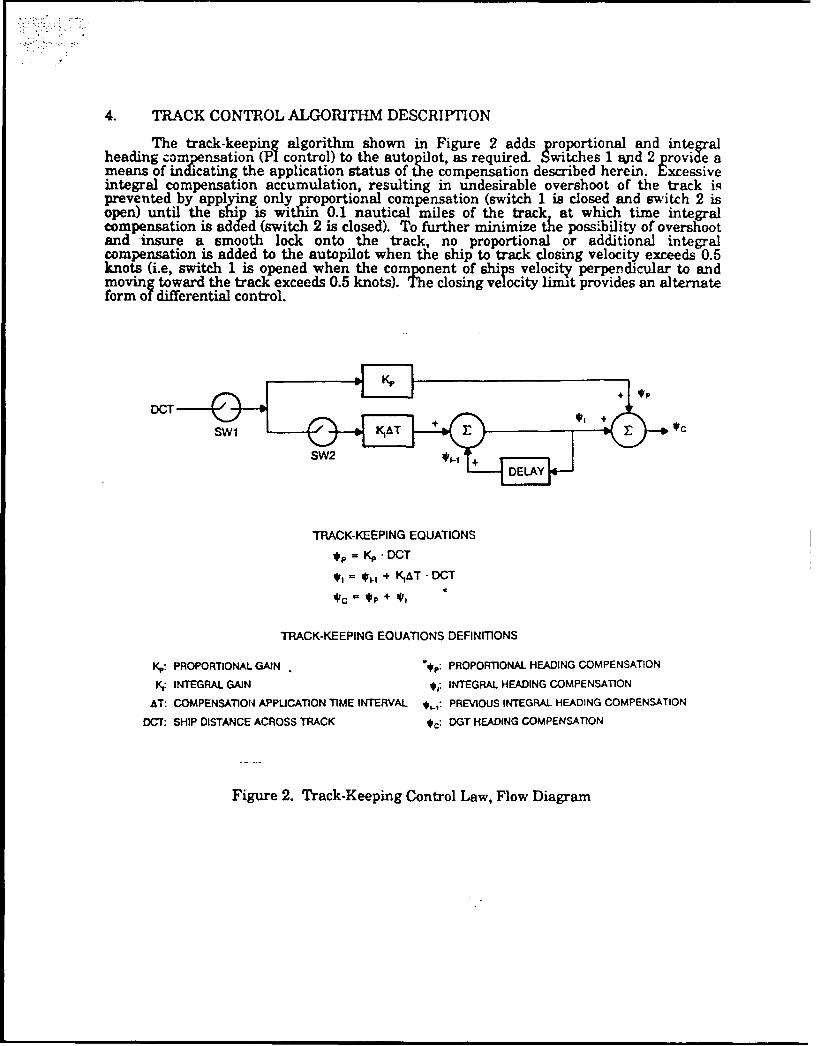
4. TRACK CONTROL ALGORITHM DESCRIPTION
The track-keeping algorithm shown in Figure 2 adds proportional and integralheading compensation (PI control) to the autopilot, as required. Switches 1 End 2 provide ameans of indicating the application status of the compensation described herein. Excessiveintegral compensation accumulation, resulting in undesirable overshoot of the track iRprevented by appl g only proportional compensation (switch 1 is closed and switch 2 isopen) until the ship is within 0.1 nautical miles of the track at which time integralcompensation is added (switch 2 is closed). To further minimize the possibility of overshootand insure a smooth lock onto the track, no proportional or additional integralcompensation is added to the autopilot when the ship to track closing velocity exceeds 0.5knots (i.e, switch 1 is opened when the component of ships velocity perpendicular to andmoving toward the track exceeds 0.5 knots). The closing velocity limit provides an alternateform of differential control.
SW2 +V.
TRACK-KEEPING EQUATIONS
,= • DCT
S= *+ ÷ K1AT" DCT
TRACK-KEEPING EQUATIONS DEFINITIONS
K,: PROPORTIONAL GAIN '•p: PROPORTIONAL HEADING COMPENSATION
Iy INTEGRAL GAIN *j: INTEGRAL HEADING COMPENSATION
AT: COMPENSATION APPUCATION TIME INTERVAL *•.: PREVIOUS INTEGRAL HEADING COMPENSATION
DCT: SHIP DISTANCE ACROSS TRACK #c: DGT HEADING COMPENSATION
Figure 2. Track-Keeping Control Law, Flow Diagram

5. ALGORITH_ M GAIN DETERMINATION
Gain constants Kp and Ki, respectively controlling the proportional and integalcompensators, were selected to yield a maximum permissib e pro portional headingcorrection of 15 degrees for a ship's off-track distance of 0.1 nautical miles from the trackand an integral time (reset rate) Ts, corresponding to a ship's nominal velocity of 15 knots.Using these initial constraints, the gain development in Figure 3 indicates design values of3 minutes for Ts, and gain values of 150 degrees per nautical mile and 3000 degrees€ pernautical mile per hour for Kp and Ki, respectively. Using a reduced order model of shipdynamics consisting of yaw and sway, rudder dynamics, and autopilot controller d naiics,application of Liapunov stability analysis techniques verified that the selected designconstants yield a stable system. While the system was in fact stable, shipboard testingshowed that the steering corrections provided by this controller were too severe for ourapplication, so the Kp and Ki gains were tuned to obtain the desired response.
K - *c&IAX 15.. - 150*1NMDCTI 0.1 NM
Ts- DCTI 0.1 NM -3 MIN
Vs SIN (-CMA) (15 KTS) SIN(Ž2~
Y Kp 150,INM I3O W OfM$ AJ PTs 3 MIN HR
"SHIP
ocrVs SIN *cDCT
DGT
Vs: NOMINAL SHIP VELOCITY
*c: HEADING COMPENSATION ANGLE
DCT: SHIP DISTANCE CROSS TRACK
Figure 3. Gain Selection Development

6. PERFORMANCE SIMULATION
A ship motion simulation computer program, featuring, linear state space models ofthe ship's sway, yaw, and roll motions, a non linear surge equation to account for rudder,sway, and coupled yaw/sway drag, and autopilot and steering h draulics models wasemployed in the performance simulation. Track-keeping algorithm performance wasevaluated through simulations of ship's response to various external factors driving the shipoff track. The simulation assumed a ship velocity of 20 knots, a 3 knot ocean currentcrossing the track at 45 degrees, and a 0.5 nautical mile initial ship offset from the track.The maximum heading correction permitted was 25 degrees for 0.33 nautical mile or greaterdistance off track, and 15 degrees otherwise. The maximum incremental heading correctionpermitted was initially 2 degrees. Further testing subsequently resulted in 0.5 degreesbeing chosen as the incremental heading correction limit. Integral compensation updateswere only introduced when the ship's distance cross track was 0.1 nautical mile or less.
The autopilot heading correction, ship's distance cross track and PI control law•aphs, provided in Figures 4, 5, and 6, respectively were generated from the simulation.The negative and positive constant slope portions of .Figure 4, reflect time frames in whichthe theoretical PI control law correctin exceeded the maximum 2 degree per incrementapplied correction limitation. In Figure 4, the size of an increment is indicated by thevertical distance between successive plot symbols. The left and right flat portions of thegraph, respectively, indicate a 25 degree maximum heading correction for ship's off trackdistance of 0.33 nautical miles or more, and a 15 degree maximum heading correctionotherwise. Finally, the curved portion of Figure 4 indicates those times where less thanmaximum allowable incremental heading corrections were required.
-2.00-
-7.00-
V) -12.00.'U
'UW
-17.00-
-22.00-
-27.00-0.00 10.00 20o00 30oo00 40100 60o00 60.,00 7000 8000
TIME(SECONDS) 10'
Figure 4. Autopilot Heading Correction Commands

Figure 5 reflects the ship's off-track distance in response to the combination of: theapplied headizg corrections indicated in Figure 4, the ocean current environment, the ship'sinitial offset from the track, and the ship's velocity. Due to the 2 degree per incrementheading correction application limit, the effect of the ocean current causes the ship toinitially move further awaqy from the track as indicated at the start of thi run. As theheading correction application increased to tle 25 degree limit permitted for offsets of 0.33nautical miles or more, the off-track distance decreases rapidly. When the off-track distancefalls below 0.33 nautical miles, the maximum heading correction application is reduced to15 degrees, resulting in a corresponding decreased rate of ship movement toward the track.Finaly, as the off-track distance falls below 0.1 nautical miles, the proportional headingcorrection gradually diminishes while the integral compensation commences. Integralcompensation builds up to the beading correction value required to compensate for thesteady state ocean current at the point of reaching zero off-track distance.
400o00j
320.00,
240.00-
i-,
00-00-
0.00'
0.00 10.00 20.0o 30.00 40.00 000 60'00 70.00 8000TIME(SECONDS) 10'
Figure 5. Simulated Ship's Off-Track Distance

Figure 6, demonstrates the proportional and integral corrections generated by the PIcontrol law. The proportional correction graph is identical in shape to the ship's off-trackdistance graph of Figure 5. In accordance with the corrmL;ion application criteria, discussedabove, the integral compensation graph indicates zero values for ship off-track distances inexcess of 0.1 nautical miles, and gradual accumulation to the value requiredto compensatefor the ocean current, in the 0.1 nautical mile off-track distance range.
LEGEND100.00"
Prop comp:-
Int comp: *,t.,,,
80.00
8•0.00
20.00-
0.00• q ...
0.00 10.0o 20.00 30.00 40100 50.00 60.00 70.00 O00
TIME (SECONDS) 10'
Figure 6. Simulation Computed Proportional and Integral Heading Corrections

7. TRACK-KEEPING IMPLEMENTATION
The automatic track-keeping system was implemented on several survey ships withvarying host computers and ship configurations as shown in Figure 7. Thý PI controlleralgorithm waz hosted in the existing navigation computer and an electrical interface wasdeveloped to handle data communications between the navigation computer and the ship'sautopilot equipment. The track-keeping interface included digital-to-ar log conversionfunctions and provided options for communications with two different types of hostcomputers, namely, the AN/UYK-20 Navy Standard mini-computer and the HP-1G0 Lcommercial mini-computeL. Figures 8 and 9, respectively show the configuration of thetracki-keeping interface designed for the two types of host computers. Autopilotconfiguration modifications entailed incorporation of circuitry to add PI controller derivedheading corrections to the selected heading. This permitted the autopilot system to functionnormally in all other respects so as to seek and lock onto the selected DCT. However, inthis case PI controller corrections cause the autopilot system to steer a rhumb line surveytrack instead of a constant heading.
Finally, sea tests were conducted to fine tune design constants for each ship'simplementation. The robustness of the design was evidenced by the fact that successfulimplementation was achieved with only minimal parameter tuning for ships with widelydivergent characteristics.
1/ IIWRITER1 NAVIGATION BRIDGE
CENTER IM rTA[. HDG ANALOG HOG "
CORR.E CTION _. 1CORRECTiON
NAVIGATION MODE SELECTION •TAKKEIGI.•I.•srNAVIGATIO STATUS ..... EE(N t 5 D OEWTHRDECOPTRINTERFACE • .AUTrOPILOT /RVOEI
/ SELFCTED -(MODIFIED) COWROL
' NE•RTIAL I NLGHG SWITCHBOARD
NAVIGATIONSYSTEM I
INRIL ANALOG HDG HO •G ANALOG HDG MK 37NAVIGATION 0 GYROCOMPASS
SYSTEM 2 " ;
SMK 29 t NLOG mDG
GYROCOMPASS
Figure 7. Track-Keeping System Integration

AM t
w91M All
I-a
'I-ftEMEIiPv
g.4"
emodMO' SIUE f
Figure 10.6ckKeig nefaeBok"1gam P100Cnigrto

8. SHIPBOARD PERFORMANCE
The integrated navigation approach to control ship's track was implernented aboardship and has performed as expected. Especially high quality track cortrol has beenconsistently achieved with the availability of GPS position. Figure 10 demonstrates twoshipboard track repeatability runs obtained in a broad ccean environment. The nearlycomplete overlap achieved in each case attests to the performance of the integratednavigation approach to control ship's track. Track repeatability to less than 120 feet hastypically been achieved.
ra
Figu:'e 10. Ship's Track Repeatability Demonstration
9. CONCLUSION
The feasibility of an integrated navigation approach for ship's track control has beensuccessfully demonstrated by simulation and actual shipboard use. The quality of the track-keeping performance is directly tied to the quality of the navigation data available. Theintegration of GPS and Loran radio navigation data with an inertial navigator and deadreckoning aids provides higher quality data under varying conditions than any single sourceof navigation data alone, thereby improvinb the quality of the track-keeping function.

AUTHOR BIOGRAPHIES
MARTIN E. LEBLANG
Mr. Leblang received a Bachelors Degree in Electrical Engineering from the CityCollege of New York in 1969 and a Master of Science Degree in Electrical Engineering fromNew York University in 1973. He was first employed in 1969 by ITT DefenseCommunications Division in Nutley, New Jersey, where he designed portions of microwavereceiving systems. In 1971, he joined Naval Strategic Systems Navigation Facility,Brooklyn New York, where he was involved in the integration of precise navigation
stems For deep ocean survey. This function was transferred to the Naval Air Developmentnter Warminster, Pennsylvania in 1973, and was realigned as the Naval Command,
Control and Ocean Surveillance Center RDT&E Division Detachment, Warminster in 1992,where Mr. Leblang performs various assignments in the field of navigation systemdevelopment, integration, analysis and testing.
JULES KRIEGQSMAN
Mr. Kriegsman received a Bachelors Degree in Electrical Engineering from the CityCollege of New York in 1959 and a Masters Degree in Electrical Engineering fromPolytechnic Institute of Brooklyn in 1970. He is a licensed Professional Engineer. Hestarted working in the field of navigation in 1959 at the Bendix Corporation in Teterboro,New Jersey, where over the next seven years he developed stability requirements for thegyro stabilized platform for the Pershing missile. He then worked one year at the EDOCorporation located in College Point New York, where he designed stabilized networks forminesweeping sensors. S..ice 1968 Mr. Kriegsman has been employed with the Departmentof the Navy first at the Naval Strategic Systems Navigation Facility at the Brooklyn NavyYard, and tien at the Naval Air Development Center in Warminster, Pennsylvania as theresult of a base transfer in 1973. The navigation function of the Naval Air DevelopmentCenter was realigned as the Naval Command, Control and Ocean Surveillance CenterRDT&E Division Detachment, Warminster in 1992. Mr. Kriegsman performs variousassignments in the field of navigation system analysis and design.