accurate non-iterative o solution to the p p...
TRANSCRIPT
Accurate Non-Iterative O(n) Solution to the PnP Problem ∗
Francesc Moreno-Noguer Vincent Lepetit Pascal Fua
Computer Vision Laboratory
Ecole Polytechnique Federale de Lausanne – 1015 Lausanne, Switzerland
{francesc.moreno,pascal.fua,vincent.lepetit}@epfl.ch
Abstract
We propose a non-iterative solution to the PnP
problem—the estimation of the pose of a calibrated camera
from n 3D-to-2D point correspondences—whose computa-
tional complexity grows linearly with n. This is in contrast
to state-of-the-art methods that are O(n5) or even O(n8),without being more accurate. Our method is applicable for
all n ≥ 4 and handles properly both planar and non-planar
configurations. Our central idea is to express the n 3D
points as a weighted sum of four virtual control points. The
problem then reduces to estimating the coordinates of these
control points in the camera referential, which can be done
in O(n) time by expressing these coordinates as weighted
sum of the eigenvectors of a 12 × 12 matrix and solving a
small constant number of quadratic equations to pick the
right weights. The advantages of our method are demon-
strated by thorough testing on both synthetic and real-data.
1. IntroductionThe aim of the Perspective-n-Point problem—PnP in
short—is to determine the position and orientation of a
camera given its intrinsic parameters and a set of n corre-
spondences between 3D points and their 2D projections. It
has many applications in Computer Vision, Robotics, Aug-
mented Reality and has received much attention in both the
Photogrammetry [21] and Computer Vision [12] communi-
ties. In particular, applications such as feature point-based
camera tracking [26, 18] require dealing with hundreds of
noisy feature points in real-time, which requires computa-
tionally efficient methods.In this paper, we introduce a non-iterative solution with
better accuracy and much lower computational complex-
ity than non-iterative state-of-the-art methods, and much
faster than iterative ones with little loss of accuracy. Our
approach is O(n) for n ≥ 4 whereas all other methods
we know of are either specialized for small fixed values
of n, very sensitive to noise, or much slower. The spe-
cialized methods include those designed to solve the P3P
problem [9, 23]. Among those that handle arbitrary val-
ues of n [8, 6, 13, 11, 23, 28, 7, 2, 9], the lowest-complexity
one [7] is O(n2) but has been shown to be unstable for noisy
2D locations [2]. This is currently addressed by algorithms
∗This work was supported in part by the Swiss National Science Foun-
dation and by funds of the European Commission under the IST-project
034307 DYVINE (Dynamic Visual Networks).
that are O(n5) [23] or even O(n8) [2] for better accuracy
whereas our O(n) approach achieves even better accuracy
and reduced sensitivity to noise, as depicted by Fig. 1 in the
n = 6 case and demonstrated for larger values of n in the
result section.
A natural alternative to non-iterative approaches are it-
erative ones [19, 5, 14, 17, 20] that rely on minimizing an
appropriate criterion. They can deal with arbitrary numbers
of correspondences and achieve excellent precision when
they converge properly. In particular Lu et al. [20] intro-
duced a very accurate algorithm, which is fast in compar-
ison with other iterative ones but slow compared to non-
iterative methods. As shown in Fig. 1, our method achieves
an accuracy that is almost as good, and is much faster and
without requiring an initial estimate. This is significant be-
cause iterative methods are prone to failure if poorly initial-
ized. For instance, Lu et al.’s approach relies on an initial
estimation of the camera pose based on a weak-perspective
assumption, which can lead to instabilities when the as-
sumption is not satisfied. This happens when the points
of the object are projected onto a small region on the side
of the image and our solution performs more robustly un-
der these circumstances. Furthermore, if maximal precision
is required our output can be used to initialize Lu et al.’s,
yielding both higher stability and faster convergence.
Our central idea was to write the coordinates of the n 3D
points as a weighted sum of four virtual control points. This
reduces the problem to estimating the coordinates of the
control points in the camera referential, which can be done
in O(n) time by expressing these coordinates as weighted
sum of the eigenvectors of a 12 × 12 matrix and solving
a small constant number of quadratic equations to pick the
right weights. The accuracy of the resulting algorithm is
better than the one of the more complex ones [23, 2]. Our
approach also extends to planar configurations, which cause
problems for some methods as discussed in [22, 24], by us-
ing three control points instead of four.
In the remainder of the paper, we first discuss related
work focusing on accuracy and computation time. We then
introduce our new formulation and derive our system of
linear and quadratic equations. Finally, we compare our
method against the state-of-the-art ones using synthetic data
and demonstrate it using real data.
1
0 1 2 3 4 5 6 7 8 9 10 11 12 13 14 150
20
40
60
80
100ro
tatio
n er
ror
(%)
Gaussian image noise (pixels)
AD
0 1 2 3 4 5 6 7 8 9 10 11 12 13 14 150
20
40
60
80
100
rota
tion
erro
r (%
)
Gaussian image noise (pixels)
Clamped DLT
0 1 2 3 4 5 6 7 8 9 10 11 12 13 14 150
20
40
60
80
100
rota
tion
erro
r (%
)
Gaussian image noise (pixels)
EPnP
0 1 2 3 4 5 6 7 8 9 10 11 12 13 14 150
20
40
60
80
100
rota
tion
erro
r (%
)
Gaussian image noise (pixels)
LHM
0 1 2 3 4 5 6 7 8 9 10 11 12 13 14 150
20
40
60
80
100
rota
tion
erro
r (%
)
Gaussian image noise (pixels)
EPnP+LHM
0 50 100 1500
0.01
0.02
0.03
0.04
0.05
0.06
0.07
number of points used to estimate pose
com
puta
tion
time
(sec
)
AD
Clamped DLT
EPnP
LHM
Clamped DLT+LHM
EPnP+LHM
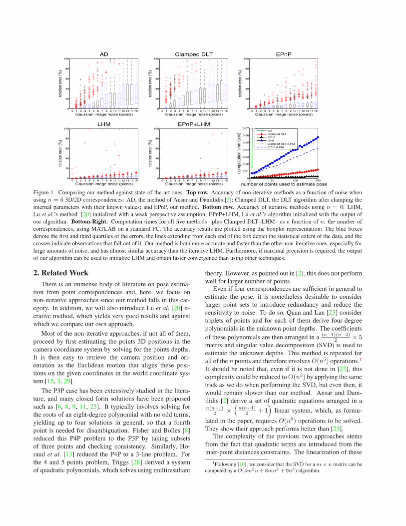
Figure 1. Comparing our method against state-of-the-art ones. Top row. Accuracy of non-iterative methods as a function of noise when
using n = 6 3D/2D correspondences: AD, the method of Ansar and Daniilidis [2]; Clamped DLT, the DLT algorithm after clamping the
internal parameters with their known values; and EPnP, our method. Bottom row. Accuracy of iterative methods using n = 6: LHM,
Lu et al.’s method [20] initialized with a weak perspective assumption; EPnP+LHM, Lu et al.’s algorithm initialized with the output of
our algorithm. Bottom-Right. Computation times for all five methods –plus Clamped DLT+LHM– as a function of n, the number of
correspondences, using MATLAB on a standard PC. The accuracy results are plotted using the boxplot representation: The blue boxes
denote the first and third quartiles of the errors, the lines extending from each end of the box depict the statistical extent of the data, and the
crosses indicate observations that fall out of it. Our method is both more accurate and faster than the other non-iterative ones, especially for
large amounts of noise, and has almost similar accuracy than the iterative LHM. Furthermore, if maximal precision is required, the output
of our algorithm can be used to initialize LHM and obtain faster convergence than using other techniques.
2. Related Work
There is an immense body of literature on pose estima-
tion from point correspondences and, here, we focus on
non-iterative approaches since our method falls in this cat-
egory. In addition, we will also introduce Lu et al. [20] it-
erative method, which yields very good results and against
which we compare our own approach.
Most of the non-iterative approaches, if not all of them,
proceed by first estimating the points 3D positions in the
camera coordinate system by solving for the points depths.
It is then easy to retrieve the camera position and ori-
entation as the Euclidean motion that aligns these posi-
tions on the given coordinates in the world coordinate sys-
tem [15, 3, 29].
The P3P case has been extensively studied in the litera-
ture, and many closed form solutions have been proposed
such as [6, 8, 9, 11, 23]. It typically involves solving for
the roots of an eight-degree polynomial with no odd terms,
yielding up to four solutions in general, so that a fourth
point is needed for disambiguation. Fisher and Bolles [8]
reduced this P4P problem to the P3P by taking subsets
of three points and checking consistency. Similarly, Ho-
raud et al. [13] reduced the P4P to a 3-line problem. For
the 4 and 5 points problem, Triggs [28] derived a system
of quadratic polynomials, which solves using multiresultant
theory. However, as pointed out in [2], this does not perform
well for larger number of points.Even if four correspondences are sufficient in general to
estimate the pose, it is nonetheless desirable to consider
larger point sets to introduce redundancy and reduce the
sensitivity to noise. To do so, Quan and Lan [23] consider
triplets of points and for each of them derive four-degree
polynomials in the unknown point depths. The coefficients
of these polynomials are then arranged in a(n−1)(n−2)
2 × 5matrix and singular value decomposition (SVD) is used to
estimate the unknown depths. This method is repeated for
all of the n points and therefore involves O(n5) operations.1
It should be noted that, even if it is not done in [23], this
complexity could be reduced to O(n3) by applying the same
trick as we do when performing the SVD, but even then, it
would remain slower than our method. Ansar and Dani-
ilidis [2] derive a set of quadratic equations arranged in an(n−1)
2 ×(
n(n+1)2 + 1
)linear system, which, as formu-
lated in the paper, requires O(n8) operations to be solved.
They show their approach performs better than [23].The complexity of the previous two approaches stems
from the fact that quadratic terms are introduced from the
inter-point distances constraints. The linearization of these
1Following [10], we consider that the SVD for a m × n matrix can be
computed by a O(4m2n + 8mn2 + 9n3) algorithm.
equations produces additional parameters, which increase
the complexity of the system. Fiore’s method [7] avoids the
need for these constraints: He initially forms a set of lin-
ear equations from which the world to camera rotation and
translation parameters are eliminated, allowing the direct
recovery of the point depths without considering the inter-
point distances. This procedure allows the estimation of the
camera pose in O(n2) operations, which makes real-time
performance possible for large n. Unfortunately, ignoring
nonlinear constraints produces poor results in the presence
of noise [2].
By contrast, our method is able to consider nonlinear
constraints but requires O(n) operations only. Furthermore,
in our synthetic experiments, it yields results that are more
accurate than those of [2].
It is also worth mentioning that for large values of none could use the Direct Linear Transformation (DLT) al-
gorithm [1, 12]. However, it ignores the intrinsic camera
parameters we assume to know here, and therefore gener-
ally leads to less stable pose estimate. A way to exploit
our knowledge of the intrinsic parameters is to clamp the
retrieved values to the known ones, but the accuracy still
remains low.
Finally, among many other iterative methods, Lu et
al.’s [20] is one of the fastest and most accurate. It min-
imizes an error expressed in 3D space, unlike many ear-
lier methods that attempt to minimize reprojection residu-
als. The main difficulty is to impose the orthonormality of
the rotation matrix. It is done by optimizing alternatively
on the translation vector and the rotation matrix. In prac-
tice, the algorithm tends to converge fast but can get stuck
in an inappropriate local minimum if incorrectly initialized.
Our experiments show our method is slightly less accurate
than Lu et al.’s when it find the correct minimum, but also
that it is faster and more stable.
3. Our Approach to the PnP ProblemLet us assume we are given a set of n reference points
whose 3D coordinates are known in the world coordinate
system and whose 2D image projections are also known.
As most of the proposed solutions to the PnP Problem, we
aim at retrieving their coordinates in the camera coordinate
system. It is then easy and standard to retrieve the orienta-
tion and translation as the Euclidean motion that aligns both
sets of coordinates [15, 3, 29].
Most existing approaches attempt to solve for the depths
of the reference points in the camera coordinate system. By
contrast, we express their coordinates as a weighted sum of
virtual control points. We need 4 non-coplanar such con-
trol points for general configurations, and only 3 for planar
configurations. Given this formulation, the coordinates of
the control points in the camera coordinate system become
the unknown of our problem. For large n’s, this is a much
smaller number of unknowns that the n depth values that
traditional approaches have to deal with and is key to our
efficient implementation.The solution of our problem can be expressed as a vector
that lies in the kernel of a matrix of size 2n× 12 or 2n× 9.
We denote this matrix as M and can be easily computed
from the 3D world coordinates of the reference points and
their 2D image projections. More precisely, it is a weighted
sum of the null eigenvectors of M. Given that the correct
linear combination is the one that yields 3D camera coordi-
nates for the control points that preserve their distances, we
can find the appropriate weights by solving small systems of
quadratic equations, which can be done at a negligible com-
putational cost. In fact, for n sufficiently large—about 15 in
our implementation—the most expensive part of this whole
computation is that of the matrix M⊤M, which grows lin-
early with n.In the remainder of this section, we first discuss our pa-
rameterization in terms of control points in the generic non-
planar case. We then derive the matrix M in whose kernel
the solution must lie and introduce the quadratic constraints
required to find the proper combination of eigenvectors. Fi-
nally, we show that this approach also applies to the planar
case.
3.1. Parameterization in the General CaseLet the reference points, that is, the n points whose 3D
coordinates are known in the world coordinate system, be
pi, i = 1, . . . , n .
Similarly, let the 4 control points we use to express their
world coordinates be
cj , j = 1, . . . , 4 .
When necessary, we will specify that the point coordinates
are expressed in the world coordinate system by using thew superscript, and in the camera coordinate system by us-
ing the c superscript. We express each reference point as a
weighted sum of the control points
pwi =
4∑
j=1
αijcwj , with
4∑
j=1
αij = 1 , (1)
where the αij are homogeneous barycentric coordinates.
They are uniquely defined and can easily be estimated. The
same relation holds in the camera coordinate system and we
can also write
pci =
4∑
j=1
αijccj . (2)
In theory the control points can be chosen arbitrarily.
However, in practice, we have found that the stability of
our method is increased by taking the centroid of the refer-
ence points as one of the control point, and select the rest in
such a way that they form a basis aligned with the principal
directions of the data. This is normal because it amounts to
conditioning the linear system of equations that are intro-
duced below using a normalization technique very close to
the one recommended for the classic DLT algorithm [12].
3.2. The Solution as Weighted Sum of EigenvectorsWe now derive the matrix M in whose kernel the so-
lution must lie given that the 2D projections of the refer-
ence points are known. Let A be the camera internal cal-
ibration matrix and {ui}i=1,...,n the 2D projections of the
{pi}i=1,...,n reference points. We have
∀i , wi
[ui
1
]= Apc
i = A
4∑
j=1
αijccj , (3)
where the wi are scalar projective parameters. We now ex-
pand this expression by considering the specific 3D coordi-
nates[xc
j , ycj , z
cj
]⊤of each cc
j control point, the 2D coor-
dinates [ui, vi]⊤
of the ui projections, and the fu, fv focal
length coefficients and the (uc, vc) principal point that ap-
pear in the A matrix. Eq. 3 then becomes
∀i , wi
ui
vi
1
=
fu 0 uc
0 fv vc
0 0 1
4∑
j=1
αij
xcj
ycj
zcj
. (4)
The unknown parameters of this linear system are the 12
control point coordinates{(xc
j , ycj , z
cj )
}j=1,...,4
and the n
projective parameters {wi}i=1,...,n. The last row of Eq. 4
implies that wi =∑4
j=1 αijzcj . Substituting this expression
in the first two rows yields two linear equations for each
reference point:4∑
j=1
αijfuxcj + αij(uc − ui)z
cj = 0 , (5)
4∑
j=1
αijfvycj + αij(vc − vi)z
cj = 0 . (6)
Note that the wi projective parameter does not appear any-
more in those equations. Hence, by concatenating them for
all n reference points, we generate a linear system of the
formMx = 0 , (7)
where x =[cc1⊤, cc
2⊤, cc
3⊤, cc
4⊤
]⊤is a 12-vector made of
the unknowns, and M is a 2n × 12 matrix, generated by
arranging the coefficients of Eqs. 5 and 6 for each reference
point. Unlike in the case of DLT, we do not have to normal-
ize the 2D projections since Eqs. 5 and 6 do not involve the
image referential system.
The solution therefore belongs to the null space, or ker-
nel, of M, and can be expressed as
x =N∑
i=1
βivi (8)
where the set vi are the columns of the right-singular vec-
tors of M corresponding to the N null singular values of
M. They can be found efficiently as the null eigenvectors
of matrix M⊤M, which is of small constant (12× 12) size.
Computing the product M⊤M has O(n) complexity, and
is the most time consuming step in our method when n is
sufficiently large, about 15 in our implementation.
5 10 15 200
0.2
0.4
0.6
0.8
1
number of points used to estimate pose
N (
%)
N=1
N=2N=3
N=4
0 5 10 150
0.2
0.4
0.6
0.8
1
Gaussian image noise (pixels)
N (
%)
N=1
N=2N=3
N=4
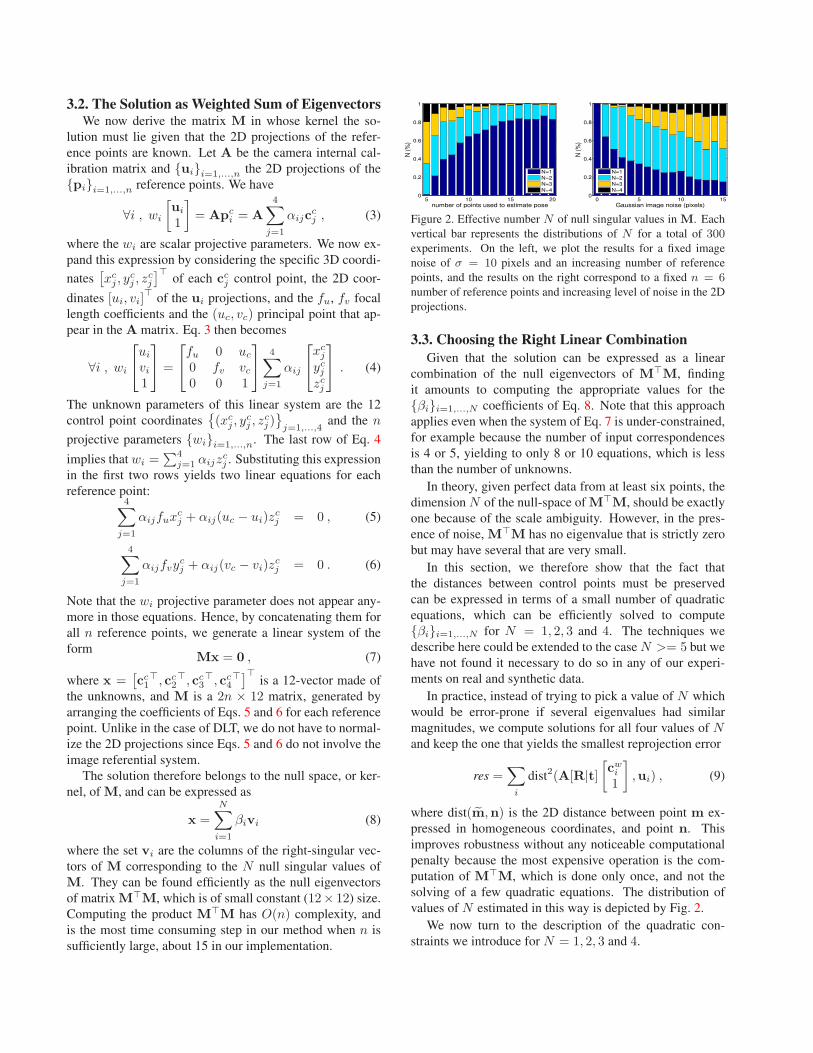
Figure 2. Effective number N of null singular values in M. Each
vertical bar represents the distributions of N for a total of 300experiments. On the left, we plot the results for a fixed image
noise of σ = 10 pixels and an increasing number of reference
points, and the results on the right correspond to a fixed n = 6number of reference points and increasing level of noise in the 2D
projections.
3.3. Choosing the Right Linear Combination
Given that the solution can be expressed as a linear
combination of the null eigenvectors of M⊤M, finding
it amounts to computing the appropriate values for the
{βi}i=1,...,N coefficients of Eq. 8. Note that this approach
applies even when the system of Eq. 7 is under-constrained,
for example because the number of input correspondences
is 4 or 5, yielding to only 8 or 10 equations, which is less
than the number of unknowns.
In theory, given perfect data from at least six points, the
dimension N of the null-space of M⊤M, should be exactly
one because of the scale ambiguity. However, in the pres-
ence of noise, M⊤M has no eigenvalue that is strictly zero
but may have several that are very small.
In this section, we therefore show that the fact that
the distances between control points must be preserved
can be expressed in terms of a small number of quadratic
equations, which can be efficiently solved to compute
{βi}i=1,...,N for N = 1, 2, 3 and 4. The techniques we
describe here could be extended to the case N >= 5 but we
have not found it necessary to do so in any of our experi-
ments on real and synthetic data.
In practice, instead of trying to pick a value of N which
would be error-prone if several eigenvalues had similar
magnitudes, we compute solutions for all four values of Nand keep the one that yields the smallest reprojection error
res =∑
i
dist2(A[R|t]
[cw
i
1
],ui) , (9)
where dist(m,n) is the 2D distance between point m ex-
pressed in homogeneous coordinates, and point n. This
improves robustness without any noticeable computational
penalty because the most expensive operation is the com-
putation of M⊤M, which is done only once, and not the
solving of a few quadratic equations. The distribution of
values of N estimated in this way is depicted by Fig. 2.
We now turn to the description of the quadratic con-
straints we introduce for N = 1, 2, 3 and 4.
Case N = 1: We simply have x = βv. We solve for
β by writing that the distances between control points as
retrieved in the camera coordinate system should be equal
to the ones computed in the world coordinate system when
using the given 3D coordinates.
Let v[i] be the sub-vector of v that corresponds to the
coordinates of the control point cci . For example, v[1] will
represent the vectors made of the three first elements of v.
Maintaining the distance between pairs of control points
(ci, cj) implies that
‖βv[i] − βv[j]‖2 = ‖cwi − cw
j ‖2 . (10)
The distances ‖cwi − cw
j ‖ are known and β computed in
closed-form as
β =
∑{i,j}∈[1;4] ‖v
[i] − v[j]‖ · ‖cwi − cw
j ‖∑{i,j}∈[1;4] ‖v
[i] − v[j]‖2. (11)
Case N = 2: We now have x = β1v1 + β2v2, and ourdistance constraints become
‖(β1v[i]1 + β2v
[i]2 )− (β1v
[j]1 + β2v
[j]2 )‖2 = ‖cw
i − cwj ‖
2. (12)
β1 and β2 only appear in the quadratic terms and we
solve for them using a technique called “linearization”
in cryptography, which was employed by [2] to estimate
the point depths. It involves solving a linear system in
[β11, β12, β22]⊤ where β11 = β2
1 , β12 = β1β2, β22 = β22 .
Since we have four control points, we can generate a lin-
ear system of six equations in the βab2:
Lβ = ρ , (13)
where L is a 6 × 3 matrix formed with the elements
of v1 and v2, ρ is a 6-vector with the squared distances
‖cwi − cw
j ‖2, and β = [β11, β12, β22]
⊤ is the vector of un-
knowns. We solve this system using the pseudoinverse of
L and choose the signs fo the βa so that all the pci have
positive z coordinates.
This yields β1 and β2 values that can be further refined
by using the formula of Eq. 11 to estimate a common scale
β so that cci = β(β1v
[i]1 +β2v
[i]2 ). Because solving Eq. 13 is
an indirect computation, the least-squares solution of Eq. 11
is more accurate in the presence of noise.
Case N = 3: As in the N = 2 case, we use the six
constraints of Eq. 12. This yields again a linear system
Lβ = ρ, although with different dimensionalities. Now L
is a square 6× 6 matrix formed with the elements of v1, v2
and v3. The number of unknowns is extended to six, being
β = [β11, β12, β13, β22, β23, β33]⊤. We follow the same
procedure as before, except that we now use the inverse of
L instead of its pseudo-inverse.
2We use the indices a and b for the β’s in order to differentiate from
the indices i and j used for the 3D points.
Case N = 4: We now have four βa unknowns and, in
theory, the six distance constraints we have been using so
far should still suffice. Unfortunately, the linearization pro-
cedure treats all 10 products βab = βaβb as unknowns and
there are not enough constraints anymore. We solve this
problem using a relinearization technique [16] whose prin-
ciple is the same as the one we use to determine the control
points coordinates.
The solution for the βab is in the null space of a first
homogeneous linear system made from the original con-
straints. The correct coefficients are found by introduc-
ing new quadratic equations and solving them again by lin-
earization, hence the name “relinearization”. These new
quadratic equations are derived from the fact that we have,
by commutativity of the multiplication
βabβcd = βaβbβcβd = βa′b′βc′d′ , (14)
where {a′, b′, c′, d′} represents any permutation of the inte-
gers {a, b, c, d}.
3.4. The Planar CaseIn the planar case, that is, when the moment matrix of
the reference points has one very small eigenvalue, we need
only three control points. The dimensionality of M and its
eigenvectors vi are reduced, but the above equations remain
mostly valid. The main difference is that the number of
quadratic constraints drops from 6 to 3. As a consequence,
we need use of the relinearization technique introduced in
the N = 4 case of the previous section for N ≥ 3.
4. ResultsWe compare the accuracy and speed of our approach
against that of state-of-the-art ones, both on simulated and
real image data.
4.1. Synthetic ExperimentsWe produced synthetic 3D-to-2D correspondences in a
640 × 480 image acquired using a virtual calibrated cam-
era with an effective focal length of fu = fv = 800 and a
principal point at (uc, vc) = (320, 240). We generated dif-
ferent sets for the input data. For the centered data, the 3D
reference points were uniformly distributed into the x,y,zinterval [−2, 2] × [−2, 2] × [4, 8]. For the uncentered data,
the ranges were modified to [1, 2] × [1, 2] × [4, 8]. We also
added Gaussian noise to the corresponding 2D point coor-
dinates, and considered a percentage of outliers, for which
the 2D coordinate was randomly selected within the whole
image.
Given the true camera rotation Rtrue and translation
ttrue, we computed the relative error of the estimated ro-
tation R by Erot(%) = ‖qtrue − q‖/‖q‖, where q and
qtrue are the normalized quaternions corresponding to the
rotation matrices. Similarly, the relative error of the esti-
mated translation t is determined by Etrans(%) = ‖ttrue−t‖/‖t‖.
Mean Rotation Error Median Rotation Error Mean Translation Error Median Translation Error
(a)Centered
n = 6
σ = 0..15
outliers=0%0 5 10 15
0
10
20
30
40
50
60
Gaussian image noise (pixels)
rota
tion
erro
r (%
)
ADClamped DLTEPnPLHMEPnP+LHM
0 5 10 150
10
20
30
40
50
60
Gaussian image noise (pixels)
rota
tion
erro
r (%
)
ADClamped DLTEPnPLHMEPnP+LHM
0 5 10 150
20
40
60
80
100
Gaussian image noise (pixels)
tran
slat
ion
erro
r (%
)
ADClamped DLTEPnPLHMEPnP+LHM
0 5 10 150
20
40
60
80
100
Gaussian image noise (pixels)
tran
slat
ion
erro
r (%
)
ADClamped DLTEPnPLHMEPnP+LHM
(b)Uncentered
n = 6
σ = 0..15
outliers=0%0 5 10 15
0
20
40
60
80
100
120
140
Gaussian image noise (pixels)
rota
tion
erro
r (%
)
ADClamped DLTEPnPLHMEPnP+LHM
0 5 10 150
20
40
60
80
100
120
140
Gaussian image noise (pixels)
rota
tion
erro
r (%
)
ADClamped DLTEPnPLHMEPnP+LHM
0 5 10 150
50
100
150
Gaussian image noise (pixels)
tran
slat
ion
erro
r (%
)
AD
Clamped DLT
EPnP
LHM
EPnP+LHM
0 5 10 150
50
100
150
Gaussian image noise (pixels)
tran
slat
ion
erro
r (%
)
AD
Clamped DLT
EPnP
LHM
EPnP+LHM
(c)Centered
n = 5..20
σ = 5
outliers=0%5 10 15 20
0
5
10
15
20
number of points used to estimate pose
rota
tion
erro
r (%
)
ADClampled DLTEPnPLHMEPnP+LHM
5 10 15 200
5
10
15
20
number of points used to estimate pose
rota
tion
erro
r (%
)
ADClampled DLTEPnPLHMEPnP+LHM
5 10 15 200
5
10
15
20
number of points used to estimate pose
tran
slat
ion
erro
r (%
)
ADClampled DLTEPnPLHMEPnP+LHM
5 10 15 200
5
10
15
20
number of points used to estimate pose
tran
slat
ion
erro
r (%
)
ADClampled DLTEPnPLHMEPnP+LHM
(d)Uncentered
n = 5..50
σ = 5
outliers=0%10 20 30 40 50
0
10
20
30
40
number of points used to estimate pose
rota
tion
erro
r (%
)
Clampled DLTEPnP
LHMEpnP+LHM
10 20 30 40 500
10
20
30
40
number of points used to estimate pose
rota
tion
erro
r (%
)
Clampled DLTEPnP
LHMEpnP+LHM
10 20 30 40 500
20
40
60
80
number of points used to estimate pose
tran
slat
ion
erro
r (%
)
Clampled DLTEPnP
LHMEpnP+LHM
10 20 30 40 500
20
40
60
80
number of points used to estimate pose
tran
slat
ion
erro
r (%
)
Clampled DLTEPnP
LHMEpnP+LHM
(e)Uncentered
n = 5..50
σ = 5
outliers=25%10 20 30 40 50
0
10
20
30
40
50
60
number of points used to estimate pose
rota
tion
erro
r (%
)
Clampled DLTEPnP
LHMEpnP+LHM
10 20 30 40 500
10
20
30
40
50
60
number of points used to estimate pose
rota
tion
erro
r (%
)
Clampled DLTEPnP
LHMEpnP+LHM
10 20 30 40 500
20
40
60
80
number of points used to estimate pose
tran
slat
ion
erro
r (%
)
Clampled DLTEPnP
LHMEpnP+LHM
10 20 30 40 500
20
40
60
80
number of points used to estimate pose
tran
slat
ion
erro
r (%
)
Clampled DLTEPnP
LHMEpnP+LHM
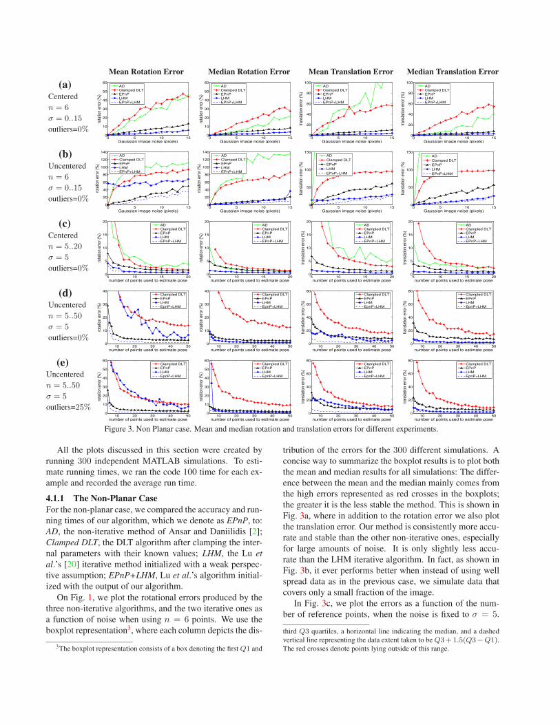
Figure 3. Non Planar case. Mean and median rotation and translation errors for different experiments.
All the plots discussed in this section were created by
running 300 independent MATLAB simulations. To esti-
mate running times, we ran the code 100 time for each ex-
ample and recorded the average run time.
4.1.1 The Non-Planar Case
For the non-planar case, we compared the accuracy and run-
ning times of our algorithm, which we denote as EPnP, to:
AD, the non-iterative method of Ansar and Daniilidis [2];
Clamped DLT, the DLT algorithm after clamping the inter-
nal parameters with their known values; LHM, the Lu et
al.’s [20] iterative method initialized with a weak perspec-
tive assumption; EPnP+LHM, Lu et al.’s algorithm initial-
ized with the output of our algorithm.
On Fig. 1, we plot the rotational errors produced by the
three non-iterative algorithms, and the two iterative ones as
a function of noise when using n = 6 points. We use the
boxplot representation3, where each column depicts the dis-
3The boxplot representation consists of a box denoting the first Q1 and
tribution of the errors for the 300 different simulations. A
concise way to summarize the boxplot results is to plot both
the mean and median results for all simulations: The differ-
ence between the mean and the median mainly comes from
the high errors represented as red crosses in the boxplots;
the greater it is the less stable the method. This is shown in
Fig. 3a, where in addition to the rotation error we also plot
the translation error. Our method is consistently more accu-
rate and stable than the other non-iterative ones, especially
for large amounts of noise. It is only slightly less accu-
rate than the LHM iterative algorithm. In fact, as shown in
Fig. 3b, it ever performs better when instead of using well
spread data as in the previous case, we simulate data that
covers only a small fraction of the image.
In Fig. 3c, we plot the errors as a function of the num-
ber of reference points, when the noise is fixed to σ = 5.
third Q3 quartiles, a horizontal line indicating the median, and a dashed
vertical line representing the data extent taken to be Q3 + 1.5(Q3−Q1).
The red crosses denote points lying outside of this range.
10−3
10−2
0
0.5
1
1.5
2
2.5
3
3.5
4
rota
tion
erro
r (%
)
computation time (sec)
EPnP
LHM
10−3
10−2
0
0.5
1
1.5
2
2.5
3
3.5
4
tran
slat
ion
erro
r (%
)
computation time (sec)
EPnP
LHM
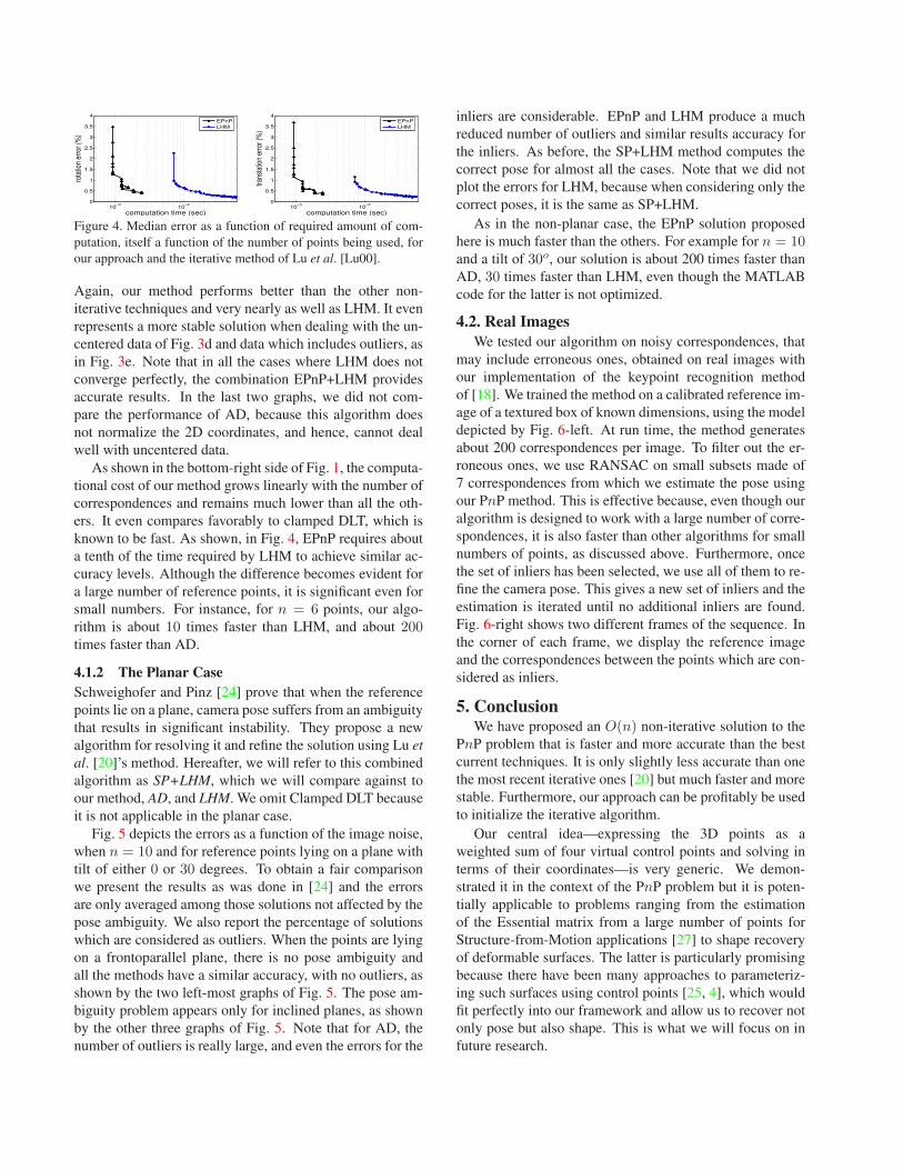
Figure 4. Median error as a function of required amount of com-
putation, itself a function of the number of points being used, for
our approach and the iterative method of Lu et al. [Lu00].
Again, our method performs better than the other non-
iterative techniques and very nearly as well as LHM. It even
represents a more stable solution when dealing with the un-
centered data of Fig. 3d and data which includes outliers, as
in Fig. 3e. Note that in all the cases where LHM does not
converge perfectly, the combination EPnP+LHM provides
accurate results. In the last two graphs, we did not com-
pare the performance of AD, because this algorithm does
not normalize the 2D coordinates, and hence, cannot deal
well with uncentered data.
As shown in the bottom-right side of Fig. 1, the computa-
tional cost of our method grows linearly with the number of
correspondences and remains much lower than all the oth-
ers. It even compares favorably to clamped DLT, which is
known to be fast. As shown, in Fig. 4, EPnP requires about
a tenth of the time required by LHM to achieve similar ac-
curacy levels. Although the difference becomes evident for
a large number of reference points, it is significant even for
small numbers. For instance, for n = 6 points, our algo-
rithm is about 10 times faster than LHM, and about 200times faster than AD.
4.1.2 The Planar Case
Schweighofer and Pinz [24] prove that when the reference
points lie on a plane, camera pose suffers from an ambiguity
that results in significant instability. They propose a new
algorithm for resolving it and refine the solution using Lu et
al. [20]’s method. Hereafter, we will refer to this combined
algorithm as SP+LHM, which we will compare against to
our method, AD, and LHM. We omit Clamped DLT because
it is not applicable in the planar case.
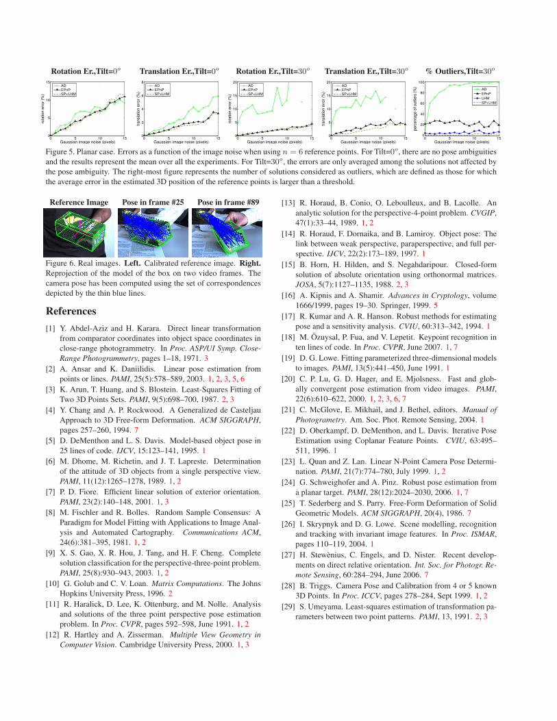
Fig. 5 depicts the errors as a function of the image noise,
when n = 10 and for reference points lying on a plane with
tilt of either 0 or 30 degrees. To obtain a fair comparison
we present the results as was done in [24] and the errors
are only averaged among those solutions not affected by the
pose ambiguity. We also report the percentage of solutions
which are considered as outliers. When the points are lying
on a frontoparallel plane, there is no pose ambiguity and
all the methods have a similar accuracy, with no outliers, as
shown by the two left-most graphs of Fig. 5. The pose am-
biguity problem appears only for inclined planes, as shown
by the other three graphs of Fig. 5. Note that for AD, the
number of outliers is really large, and even the errors for the
inliers are considerable. EPnP and LHM produce a much
reduced number of outliers and similar results accuracy for
the inliers. As before, the SP+LHM method computes the
correct pose for almost all the cases. Note that we did not
plot the errors for LHM, because when considering only the
correct poses, it is the same as SP+LHM.
As in the non-planar case, the EPnP solution proposed
here is much faster than the others. For example for n = 10and a tilt of 30o, our solution is about 200 times faster than
AD, 30 times faster than LHM, even though the MATLAB
code for the latter is not optimized.
4.2. Real Images
We tested our algorithm on noisy correspondences, that
may include erroneous ones, obtained on real images with
our implementation of the keypoint recognition method
of [18]. We trained the method on a calibrated reference im-
age of a textured box of known dimensions, using the model
depicted by Fig. 6-left. At run time, the method generates
about 200 correspondences per image. To filter out the er-
roneous ones, we use RANSAC on small subsets made of
7 correspondences from which we estimate the pose using
our PnP method. This is effective because, even though our
algorithm is designed to work with a large number of corre-
spondences, it is also faster than other algorithms for small
numbers of points, as discussed above. Furthermore, once
the set of inliers has been selected, we use all of them to re-
fine the camera pose. This gives a new set of inliers and the
estimation is iterated until no additional inliers are found.
Fig. 6-right shows two different frames of the sequence. In
the corner of each frame, we display the reference image
and the correspondences between the points which are con-
sidered as inliers.
5. ConclusionWe have proposed an O(n) non-iterative solution to the
PnP problem that is faster and more accurate than the best
current techniques. It is only slightly less accurate than one
the most recent iterative ones [20] but much faster and more
stable. Furthermore, our approach can be profitably be used
to initialize the iterative algorithm.
Our central idea—expressing the 3D points as a
weighted sum of four virtual control points and solving in
terms of their coordinates—is very generic. We demon-
strated it in the context of the PnP problem but it is poten-
tially applicable to problems ranging from the estimation
of the Essential matrix from a large number of points for
Structure-from-Motion applications [27] to shape recovery
of deformable surfaces. The latter is particularly promising
because there have been many approaches to parameteriz-
ing such surfaces using control points [25, 4], which would
fit perfectly into our framework and allow us to recover not
only pose but also shape. This is what we will focus on in
future research.
Rotation Er.,Tilt=0o Translation Er.,Tilt=0o Rotation Er.,Tilt=30o Translation Er.,Tilt=30o % Outliers,Tilt=30o
0 5 10 150
5
10
15
Gaussian image noise (pixels)
rota
tion e
rror
(%)
AD
EPnP
SP+LHM
0 5 10 150
2
4
6
8
Gaussian image noise (pixels)tr
ansl
atio
n e
rror
(%)
AD
EPnP
SP+LHM
0 5 10 150
5
10
15
20
Gaussian image noise (pixels)
rota
tion e
rror
(%)
AD
EPnP
SP+LHM
0 5 10 150
5
10
15
20
Gaussian image noise (pixels)
transl
atio
n e
rror
(%)
AD
EPnP
SP+LHM
0 5 10 150
20
40
60
80
100
Gaussian image noise (pixels)
perc
enta
ge o
f outli
ers
(%
)
AD
EPnP
LHM
SP+LHM
Figure 5. Planar case. Errors as a function of the image noise when using n = 6 reference points. For Tilt=0o, there are no pose ambiguities
and the results represent the mean over all the experiments. For Tilt=30o, the errors are only averaged among the solutions not affected by
the pose ambiguity. The right-most figure represents the number of solutions considered as outliers, which are defined as those for which
the average error in the estimated 3D position of the reference points is larger than a threshold.
Reference Image Pose in frame #25 Pose in frame #89
Figure 6. Real images. Left. Calibrated reference image. Right.
Reprojection of the model of the box on two video frames. The
camera pose has been computed using the set of correspondences
depicted by the thin blue lines.
References
[1] Y. Abdel-Aziz and H. Karara. Direct linear transformation
from comparator coordinates into object space coordinates in
close-range photogrammetry. In Proc. ASP/UI Symp. Close-
Range Photogrammetry, pages 1–18, 1971. 3
[2] A. Ansar and K. Daniilidis. Linear pose estimation from
points or lines. PAMI, 25(5):578–589, 2003. 1, 2, 3, 5, 6
[3] K. Arun, T. Huang, and S. Blostein. Least-Squares Fitting of
Two 3D Points Sets. PAMI, 9(5):698–700, 1987. 2, 3
[4] Y. Chang and A. P. Rockwood. A Generalized de Casteljau
Approach to 3D Free-form Deformation. ACM SIGGRAPH,
pages 257–260, 1994. 7
[5] D. DeMenthon and L. S. Davis. Model-based object pose in
25 lines of code. IJCV, 15:123–141, 1995. 1
[6] M. Dhome, M. Richetin, and J. T. Lapreste. Determination
of the attitude of 3D objects from a single perspective view.
PAMI, 11(12):1265–1278, 1989. 1, 2
[7] P. D. Fiore. Efficient linear solution of exterior orientation.
PAMI, 23(2):140–148, 2001. 1, 3
[8] M. Fischler and R. Bolles. Random Sample Consensus: A
Paradigm for Model Fitting with Applications to Image Anal-
ysis and Automated Cartography. Communications ACM,
24(6):381–395, 1981. 1, 2
[9] X. S. Gao, X. R. Hou, J. Tang, and H. F. Cheng. Complete
solution classification for the perspective-three-point problem.
PAMI, 25(8):930–943, 2003. 1, 2
[10] G. Golub and C. V. Loan. Matrix Computations. The Johns
Hopkins University Press, 1996. 2
[11] R. Haralick, D. Lee, K. Ottenburg, and M. Nolle. Analysis
and solutions of the three point perspective pose estimation
problem. In Proc. CVPR, pages 592–598, June 1991. 1, 2
[12] R. Hartley and A. Zisserman. Multiple View Geometry in
Computer Vision. Cambridge University Press, 2000. 1, 3
[13] R. Horaud, B. Conio, O. Leboulleux, and B. Lacolle. An
analytic solution for the perspective-4-point problem. CVGIP,
47(1):33–44, 1989. 1, 2
[14] R. Horaud, F. Dornaika, and B. Lamiroy. Object pose: The
link between weak perspective, paraperspective, and full per-
spective. IJCV, 22(2):173–189, 1997. 1
[15] B. Horn, H. Hilden, and S. Negahdaripour. Closed-form
solution of absolute orientation using orthonormal matrices.
JOSA, 5(7):1127–1135, 1988. 2, 3
[16] A. Kipnis and A. Shamir. Advances in Cryptology, volume
1666/1999, pages 19–30. Springer, 1999. 5
[17] R. Kumar and A. R. Hanson. Robust methods for estimating
pose and a sensitivity analysis. CVIU, 60:313–342, 1994. 1
[18] M. Ozuysal, P. Fua, and V. Lepetit. Keypoint recognition in
ten lines of code. In Proc. CVPR, June 2007. 1, 7
[19] D. G. Lowe. Fitting parameterized three-dimensional models
to images. PAMI, 13(5):441–450, June 1991. 1
[20] C. P. Lu, G. D. Hager, and E. Mjolsness. Fast and glob-
ally convergent pose estimation from video images. PAMI,
22(6):610–622, 2000. 1, 2, 3, 6, 7
[21] C. McGlove, E. Mikhail, and J. Bethel, editors. Manual of
Photogrametry. Am. Soc. Phot. Remote Sensing, 2004. 1
[22] D. Oberkampf, D. DeMenthon, and L. Davis. Iterative Pose
Estimation using Coplanar Feature Points. CVIU, 63:495–
511, 1996. 1
[23] L. Quan and Z. Lan. Linear N-Point Camera Pose Determi-
nation. PAMI, 21(7):774–780, July 1999. 1, 2
[24] G. Schweighofer and A. Pinz. Robust pose estimation from
a planar target. PAMI, 28(12):2024–2030, 2006. 1, 7
[25] T. Sederberg and S. Parry. Free-Form Deformation of Solid
Geometric Models. ACM SIGGRAPH, 20(4), 1986. 7
[26] I. Skrypnyk and D. G. Lowe. Scene modelling, recognition
and tracking with invariant image features. In Proc. ISMAR,
pages 110–119, 2004. 1
[27] H. Stewenius, C. Engels, and D. Nister. Recent develop-
ments on direct relative orientation. Int. Soc. for Photogr. Re-
mote Sensing, 60:284–294, June 2006. 7
[28] B. Triggs. Camera Pose and Calibration from 4 or 5 known
3D Points. In Proc. ICCV, pages 278–284, Sept 1999. 1, 2
[29] S. Umeyama. Least-squares estimation of transformation pa-
rameters between two point patterns. PAMI, 13, 1991. 2, 3