accessories or air aes air sses - versa home · 1 ei acc accessories or air aes air sses versa...
TRANSCRIPT
1
BULLETIN ACC-2017
ACCESSORIES FOR AIR VALVES & AIR SYSTEMS
Versa Products Company, Inc., 22 Spring Valley Road, Paramus, New Jersey, USA 07652 ▪ TEL: 201-843-2400 FAX: 201-843-2931 Versa BV, Prins Willem Alexanderlann 1429, 7312 GB Apeldoorn, The Netherlands ▪ TEL: +31-55-3681900 FAX: +31-55-3681909
BB
RVDE
FCV
SI
QEBC
SV
BV
DEDE
ISO 9001
CERTIFIED

ACCESSORIES
2
FLOW CONTROL, CHECK & NEEDLE VALVES ............. Page 4
BLEED VALVES ........................................................ Page 5
Warranty ............................................................ Back Cover
CONTENTS GUIDE
QUICK EXHAUST VALVES .......................................... Page 8
DUST EXCLUDERS & VENT SCREEN........................... Page 3
STATUS INDICATOR .................................................. Page 7
BLOCK & BLEED VALVE .............................................. Page 11
PRESSURE RELIEF VALVE ....................................... Page 11
CONTROL VALVES .................................................... Page 5
HAZARDOUS LOCATION JUNCTION BOX .................. Page 10
ELECTRICAL QUICK EXHAUST VALVES ...................... Page 9
SHUTTLE VALVES ..................................................... Page 6
03-2017

DUST EXCLUDER
THREAD SIZE
PRODUCT NUMBER DIMENSIONS IN INCH (MM) Weights in lbs (kg)
ALUMINUMSTAINLESS
STEEL†ALUMINUM STAINLESS STEEL ALUMINUM STAINLESS
STEELA B A B⅛” NPT DE-2 1.56” (40) 1.25” (32) 0.07 (0.03)¼” NPT DE-3 DE-3-316 1.56” (40) 1.25” (32) 1.18” (30) 1.25” (32) 0.07 (0.03) 0.15 (0.07)⅜” NPT DE-4 DE-4-316 1.62” (41) 1.25” (32) 1.25” (32) 1.25” (32) 0.07 (0.03) 0.17 (0.08)½” NPT DE-5 DE-5-316 1.62” (41) 1.25” (32) 1.25” (32) 1.25” (32) 0.07 (0.03) 0.19 (0.09)¾” NPT DE-6 DE-6-316 2.0” (51) 1.37” (35) 2.0” (51) 1.37” (35) 0.11 (0.05) 0.30 (0.13)1” NPT DE-7 DE-7-316 2.0” (51) 1.37” (35) 2.0” (51) 2.0” (51) 0.12 (0.06) 0.30 (0.13)
VENT SCREEN
THREAD SIZE PRODUCT NUMBERMATERIAL 316 A HEX WEIGHTS
lbs (kg)⅛” NPT MFS-2-316 0.69 (17.5 ) .5 (12.7 ) 0.02 (0.009)¼” NPT MFS-3-316 0.88 (22.4 ) .625 ( 15.9) 0.038 (0.017)⅜” NPT MFS-4-316 1.00 (25.4 ) .75 (19 ) 0.04 (0.018)½” NPT MFS-5-316 1.19 (30.2) 1.0 (25.4 ) 0.048 (0.02)¾” NPT MFS-6-316 1.50 (38.1 ) 1.12 (28.4 ) 0.08 (0.036)1” NPT MFS-7-316 1.63 (41.4 ) 1.5 (38.1 ) 0.08 (0.036)
ACCESSORIES
3
Versa Dust Excluders are available in aluminum and 316 Stainless Steel. They are screwed into the exhaust port of a directional control valve and offer effective protection against dirt, dust, moisture and insects entering the valve, through the exhaust port, without obstructing the flow.
The function of the Versa Dust Excluder is based on a flexible seal resting on a large diameter seat.This principle offers: - Tightly closed exhaust port - Low ‘break away’ pressure - Large flow capacity - Self cleaning action.
Materials
Range: 0 to 200 psi (14 bar) pneumatic
For best protection Dust Excluders are preferably mounted such that the outlet opens to the side or down.
Aluminum body with NBR (Nitrile) seal316 Stainless Steel body with CR (Neoprene) seal
DUST EXCLUDERS
(For Pneumatic Application Only)a range of unique Dust Excluders and Vent Screens made from Aluminum or 316 Stainless Steel
†conforms to NACE standard MR-01-75
General Description
Functional Description
Pressures
Flow Symbol
Mounting
Sizes/Connections/Types/Dimensions/Weights
VENT SCREENS
General Description
Dust Excluders Vent Screen
Versa Vent Screens are available in 316 Stainless Steel. Threaded into the exhaust port of a directional control valve they offer effective protection against dirt, dust and insects entering the valve, with minimal effect on flow.
The function of the Versa Vent Screen is based on a special designed stainless steel wire screen.This principle offers: - Low profile - High mechanical resistance - Sound damping -Exceptional corrosion resistance
Functional Description
Materials
Range: 0 to 300 psi (20 bar) pneumatic
For best protection Vent Screens are preferably mounted such that the outlet opens to the side or down.
316 Stainless Steel
†conforms to NACE standard MR-01-75
Pressures
Mounting
VENT SCREEN
DUSTEXCLUDER
Flow Symbol
A
B
VERSAN.J. U.S.A. &
NETHERLANDS
HEX
A
Part number, Flow rate, Weight & Dimensions FCV CV NV Dimensions
THREAD SIZE
PRODUCT NUMBER
Cv Weights PRODUCT NUMBER Cv
Weights PRODUCT NUMBER Cv
Weights Dimensions Inch (mm)ControlledDirection
Uncontrolled Direction lbs (kg) lbs (kg) lbs (kg) A B FCV B CV B NV C Mounting
Hole Ø
¼” FCV-3-316 0** to 2.0 2.0 0.70
(0.32) CV-3-316 2.0 0.54 (0.24) NV-3-316 0 to
2.00.50
(0.22)2.5
(63.5)3.23
(82.0)2.3
(58.4)2.59
(65.7)1
(25.4).22
(5.6)
½” FCV-5-316 0**to 5.0 5.0 1.1 (0.5) CV-5-316 5.0 0.86
(0.4) NV-5-316 0 to 5.0
0.9 (0.4)
3.35 (85.2)
4.1 (104.1)
2.84 (72.2)
3.1(79)
1.25 (31.8)
.22 (5.6)
1” FCV-7-316 0** to 9.5 13.6 3.9
(1.8) CV-7-316 13.6 3.1(1.4) — — — — — — — — —
ACCESSORIES
4
FLOW CONTROL
a Family of Stainless Steel “FULL” Flow Control Valves
CHECK
Flow Control Valve Check Valve
Specifications FCV CV NV
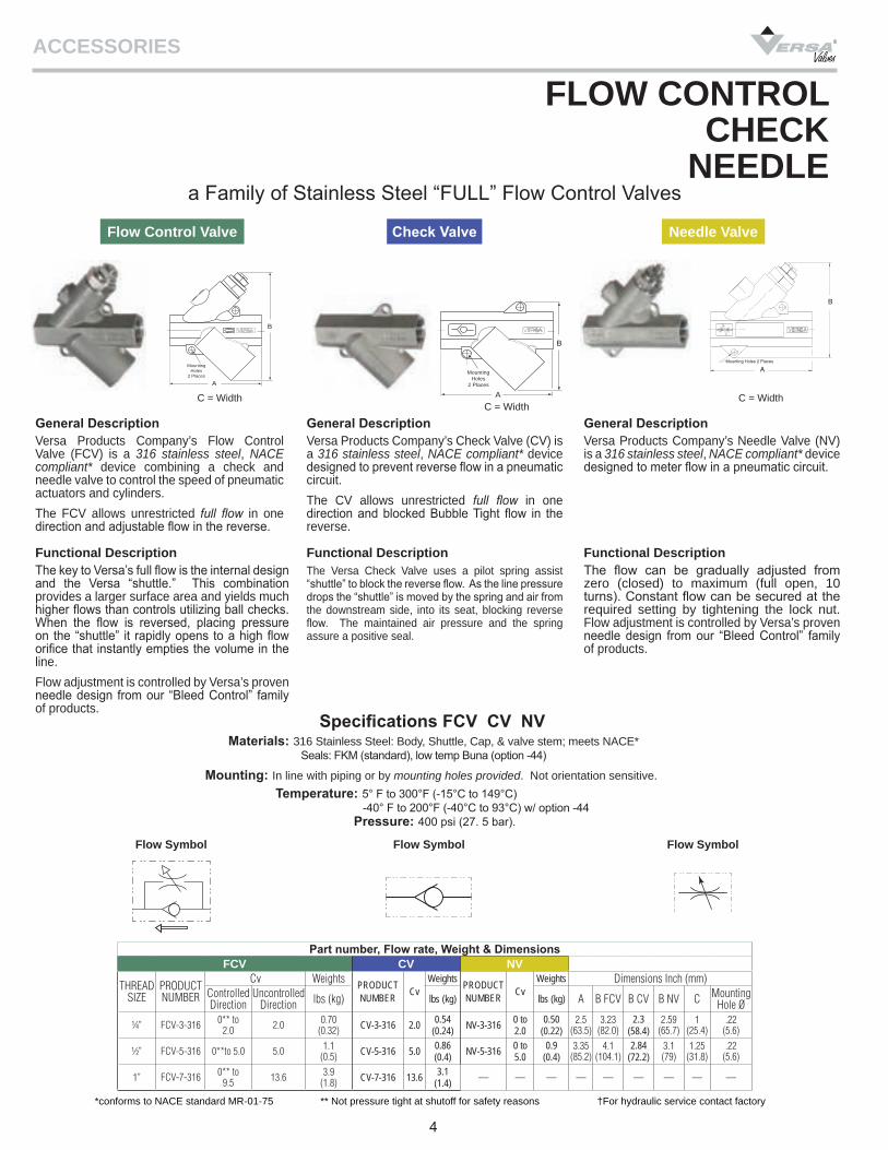
General DescriptionVersa Products Company’s Flow Control Valve (FCV) is a 316 stainless steel, NACE compliant* device combining a check and needle valve to control the speed of pneumatic actuators and cylinders.The FCV allows unrestricted full flow in one direction and adjustable flow in the reverse.
Functional DescriptionThe key to Versa’s full flow is the internal design and the Versa “shuttle.” This combination provides a larger surface area and yields much higher flows than controls utilizing ball checks. When the flow is reversed, placing pressure on the “shuttle” it rapidly opens to a high flow orifice that instantly empties the volume in the line.Flow adjustment is controlled by Versa’s proven needle design from our “Bleed Control” family of products.
General DescriptionVersa Products Company’s Check Valve (CV) is a 316 stainless steel, NACE compliant* device designed to prevent reverse flow in a pneumatic circuit.The CV allows unrestricted full flow in one direction and blocked Bubble Tight flow in the reverse.
Functional DescriptionThe Versa Check Valve uses a pilot spring assist “shuttle” to block the reverse flow. As the line pressure drops the “shuttle” is moved by the spring and air from the downstream side, into its seat, blocking reverse flow. The maintained air pressure and the spring assure a positive seal.
Materials: 316 Stainless Steel: Body, Shuttle, Cap, & valve stem; meets NACE* Seals: FKM (standard), low temp Buna (option -44)
Mounting: In line with piping or by mounting holes provided. Not orientation sensitive.Temperature: 5° F to 300°F (-15°C to 149°C) -40° F to 200°F (-40°C to 93°C) w/ option -44
*conforms to NACE standard MR-01-75 ** Not pressure tight at shutoff for safety reasons †For hydraulic service contact factory
C = WidthC = Width
Flow SymbolFlow Symbol
General DescriptionVersa Products Company’s Needle Valve (NV) is a 316 stainless steel, NACE compliant* device designed to meter flow in a pneumatic circuit.
Functional DescriptionThe flow can be gradually adjusted from zero (closed) to maximum (full open, 10 turns). Constant flow can be secured at the required setting by tightening the lock nut. Flow adjustment is controlled by Versa’s proven needle design from our “Bleed Control” family of products.
Needle Valve
C = Width
Flow Symbol
NEEDLE
Pressure: 400 psi (27. 5 bar).
MountingHoles
2 Places
A
B
MountingHoles
2 Places
A
B
A
B
Mounting Holes 2 Places

CONNECTIONS PRODUCT NUMBER DIMENSIONS IN INCH (MM) WEIGHTSPORT SIZE BRASS STAINLESS STEEL A B C D E lbs (Kg)
⅛” NPT BC-2 1.31” (33.3) 0.75” (19.1) 0.31” (7.9) 0.19” (4.8) 0.56” (14.3) 0.07 (0.03)¼” NPT BC-3 BC-3-316 1.31” (33.3) 0.75” (19.1) 0.31” (7.9) 0.19” (4.8) 0.56” (14.3) 0.08 (0.04)⅜” NPT BC-4 BC-4-316 1.56” (39.7) 0.94” (23.8) 0.38” (9.5) 0.25” (6.4) 0.69” (17.5) 0.13 (0.06)½’ NPT BC-5 BC-5-316 1.63” (41.3) 1.00” (25.4) 0.38” (9.5) 0.25” (6.4) 0.88” (22.2) 0.15 (0.07)¾” NPT BC-6 BC-6-316 2.44” (61.9) 1.50” (38.1) 0.50” (12.7) 0.25” (6.4) 1.31” (33.3) 0.55 (0.25)1” NPT BC-7 BC-7-316 2.44” (61.9) 1.50” (38.1) 0.50” (12.7) 0.25” (6.4) 1.31” (33.3) 0.62 (0.28)
ACCESSORIES
5
Versa Bleed Control Valves provide an economical, effective flow control in pneumatic applications.They can be screwed into the exhaust port of any Versa directional control valve to offer “built-in” cylinder speed control.
The Versa Bleed Control Valve has a precision machined needle. The flow area, through which the air - or any other gas - passes to the atmosphere, can be finely adjusted by turning the needle in or out. After the Bleed Control Valve has been adjusted to suit, it can be securely locked at its setting with the lock nut provided.
Exhausting flow can be gradually adjusted from zero (closed) to maximum (full open). Constant flow can be secured at the required setting by tightening the lock nut.
All parts: - Brass or 316 Stainless Steel†
Range: 0 to 200 psi (14 bar) air
valve exhaust portMaterials
Pressure
BLEED CONTROL VALVES(For Pneumatic application Only)
a range of Bleed Control Valves in different sizes, made of Brass or 316 Stainless Steel
Flow
Sizes/Connections/Types/Dimensions/Weights
General Description
Functional Description
†Conforms to NACE standard MR-01-75
BLEED VALVESa low cost, simple way to manually or mechanically control bleed functions
These versatile valves can be used to operate a bleed pilot control valve. Bleed valves are used to vent pressure from one end of the control valve to allow pressure from the opposite end to shift the spool, changing the flow patternInstallation can be made directly on the pilot cap or at a remote location by simply running a single line from the bleed button valve to the pilot cap.
Body: BrassPlunger & Spring: 440 & 302 Stainless SteelSeals: NBR (Nitrile)
Range: 0 to 200 psi (0 to 14 bar) air
Product NumberBV-2
Materials
Pressures
Functional Description
Flow Symbol
(For Pneumatic Applications Only)
⅜” (9.5) Ø
(26.2)
Dimensions: Inches (mm)
½” (12.7) HEX
⅛” NPT
1.03
With a Versa 5/2 or 5/3 four-way valve - having a separate exhaust port for each side of a double acting cylinder - the speed in one direction of stroke may be set at a different speed than the other stroke.
Flow Symbol
D
C
B
A
E
Type: Brass Stainless Steel
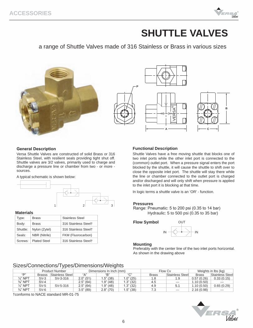
Body: Brass 316 Stainless Steel†
Shuttle: Nylon (Zytel) 316 Stainless Steel†
Seals: NBR (Nitrile) FKM (Fluorocarbon)
Screws: Plated Steel 316 Stainless Steel†
Product Number Dimensions In Inch (mm) Flow Cv Weights in lbs (kg) “P” Brasss Stainless Steel “A” “B” “C” Brass Stainless Steel Brass Stainless Steel
¼” NPT SV-3 SV-3-316 2.0” (51) 1.5” (38) 1.0” (25) 1.8 1.9 0.57 (0.26) 0.33 (0.15)⅜” NPT SV-4 2.5” (64) 1.9” (48) 1.3” (32) 4.5 — 1.10 (0.50) —½” NPT SV-5 SV-5-316 2.5” (64) 1.9” (48) 1.3” (32) 4.9 5.1 1.10 (0.50) 0.65 (0.29)¾” NPT SV-6 3.5” (89) 2.8” (70) 1.5” (38) 7.3 — 2.16 (0.98) —
ACCESSORIES
6
Shuttle Valves have a free moving shuttle that blocks one of two inlet ports while the other inlet port is connected to the (common) outlet port. When a pressure signal enters the port blocked by the shuttle, it will cause the shuttle to shift over to close the opposite inlet port. The shuttle will stay there while the line or chamber connected to the outlet port is charged and/or discharged and will only shift when pressure is applied to the inlet port it is blocking at that time.
In logic terms a shuttle valve is an ‘OR’ - function.
Versa Shuttle Valves are constructed of solid Brass or 316 Stainless Steel, with resilient seals providing tight shut off. Shuttle valves are 3/2 valves, primarily used to charge and discharge a pressure line or chamber from two - or more - sources.
A typical schematic is shown below:
Preferably with the center line of the two inlet ports horizontal. As shown in the drawing above
SHUTTLE VALVESa range of Shuttle Valves made of 316 Stainless or Brass in various sizes
†conforms to NACE standard MR-01-75
General Description Functional Description
Materials
Pressures
Flow Symbol
Mounting
Range: Pneumatic: 5 to 200 psi (0.35 to 14 bar) Hydraulic: 5 to 500 psi (0.35 to 35 bar)
Sizes/Connections/Types/Dimensions/Weights
P
A C
B
VE
RS
A ®
1 2 3
ININ
OUT
Operating Pressure RangeDepressurized Pressurized
Product Number 0 psi (0 bar) 8 psi (0.55 bar) to 200 psi (14 bar)SI-2-316 SI-2-316-403GR SI-2-316-403YG SI-2-316-403GYSI-2-316-403BGSI-2-316-403BR
Red (R) Green (G) Yellow (Y) Green (G)Black (B)Black (B)
Green Red
Green YellowGreenRed
ACCESSORIES
7
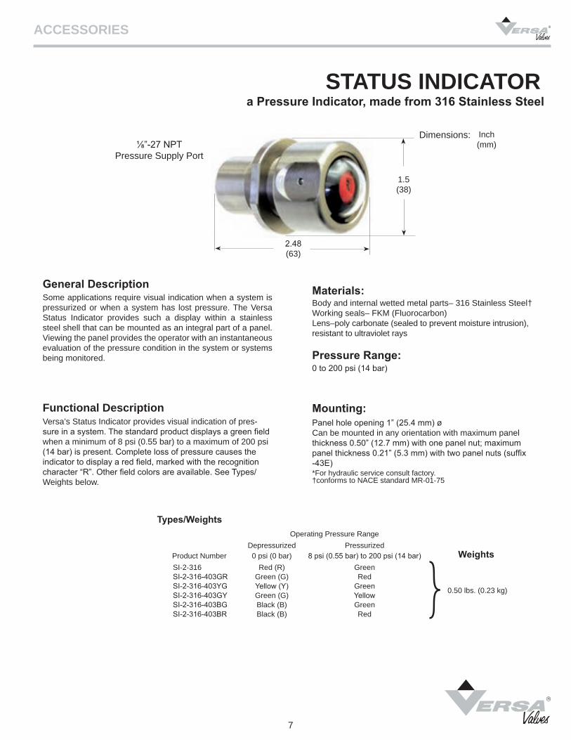
Some applications require visual indication when a system is pressurized or when a system has lost pressure. The Versa Status Indicator provides such a display within a stainless steel shell that can be mounted as an integral part of a panel. Viewing the panel provides the operator with an instantaneous evaluation of the pressure condition in the system or systems being monitored.
Versa’s Status Indicator provides visual indication of pres-sure in a system. The standard product displays a green field when a minimum of 8 psi (0.55 bar) to a maximum of 200 psi (14 bar) is present. Complete loss of pressure causes the indicator to display a red field, marked with the recognition character “R”. Other field colors are available. See Types/Weights below.
Pressure Range:
Panel hole opening 1” (25.4 mm) øCan be mounted in any orientation with maximum panel thickness 0.50” (12.7 mm) with one panel nut; maximum panel thickness 0.21” (5.3 mm) with two panel nuts (suffix -43E)
Types/Weights
*For hydraulic service consult factory.
Body and internal wetted metal parts– 316 Stainless Steel†Working seals– FKM (Fluorocarbon)Lens–poly carbonate (sealed to prevent moisture intrusion), resistant to ultraviolet rays
0 to 200 psi (14 bar)
STATUS INDICATORa Pressure Indicator, made from 316 Stainless Steel
†conforms to NACE standard MR-01-75
General Description
Functional Description Mounting:
0.50 lbs. (0.23 kg)
Weights
⅛”-27 NPT Pressure Supply Port
2.48 (63)
Inch (mm)
Dimensions:
1.5 (38)
Materials:
Weights lbs (kg)QE-3 QE-3-316 QE-5-316 QE-6-316 QE-7-316QE-9-316
1.12 (0.53) 0.81 (0.37 2.16 (0.98) 2.44 (1.11)27.0 (12.2)26.6 (12.1)
QE-3QE-3-316QE-5-316
-20°F (-29°C) to +200°F (+93°C)
QE-6-316 Standard -30°F (-34°C) to +250°F (+121°C) Optional -EP* -60°F (-51°F) to +300°F (+149°C)QE-7-316QE-9-316 Standard -5°F (-15°C) to +194°F (+90°C) Optional -44 -40°F (-40°C) to +194°F (+90°C) Optional -T40** -62°F (-52°F) to +194°F (+90°C)
SizePRODUCT NUMBER PRESSURES
FLOW Cv MATERIALS
Inlet Cyl Exhaust Inlet Exhaust Body Seals Fasteners
1/4” NPT 1/4” NPT 3/8” NPT QE-3 5-150 psi (0.35 - 10 bar)3.0 3.3
Electroless NickelPlated Brass FKM (Fluorocarbon) O rings
CR (Neoprene) coated nylon flapper
316Stainless
Steel
1/4” NPT 1/4” NPT 3/8” NPT QE-3-316 5-150 psi (0.35 - 10 bar) Investment cast 316LStainless Steel
(conforms to NACE MR-01-75)
1/2” NPT 1/2” NPT 3/4” NPT QE-5-316 5-150 psi (0.35 - 10 bar) 3.8 8.8
3/4” NPT 3/4” NPT 1” NPT QE-6-316 15-175 psi (1 - 12 bar) 4.6 13.6 FKM (Fluorocarbon) O ringsCR (Neoprene) single lip seal
1” NPT 1½” NPT 1½” NPT QE-7-316 5-175 psi (0.3 - 12 bar) Std & -445 to 125 psi (0.3 to 8.5 Bar) for -T40 20 52 316L Stainless Steel
(conforms to NACE MR-01-75)
FKM (Fluorocarbon) O rings
1½” NPT 1½” NPT 1½” NPT QE-9-316 5-175 psi (0.3 - 12 bar) Std & -445 to 125 psi (0.3 to 8.5 Bar) for -T40 23 52
ACCESSORIES
8
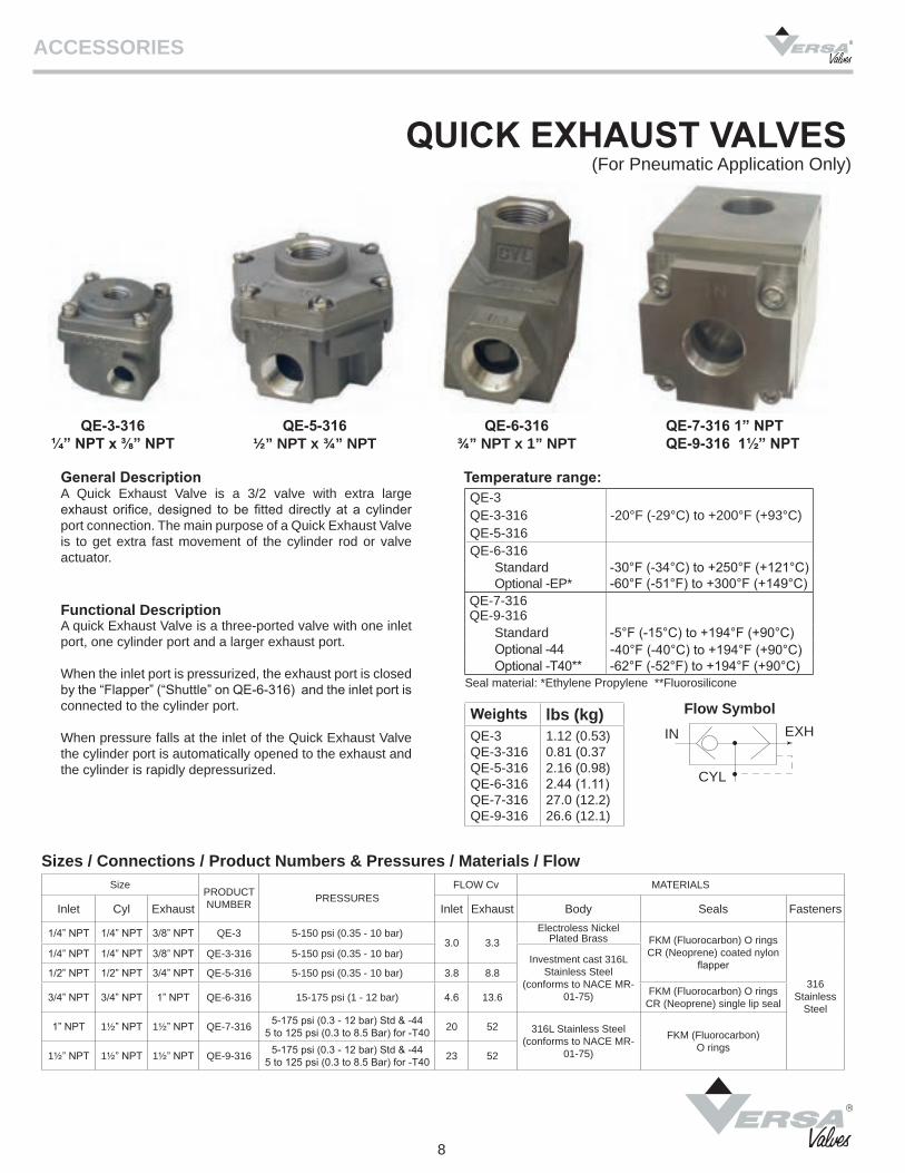
QUICK EXHAUST VALVES(For Pneumatic Application Only)
Temperature range:A Quick Exhaust Valve is a 3/2 valve with extra large exhaust orifice, designed to be fitted directly at a cylinder port connection. The main purpose of a Quick Exhaust Valve is to get extra fast movement of the cylinder rod or valve actuator.
General Description
Functional Description
Sizes / Connections / Product Numbers & Pressures / Materials / Flow
QE-5-316½” NPT x ¾” NPT
QE-3-316¼” NPT x ⅜” NPT
QE-6-316¾” NPT x 1” NPT
A quick Exhaust Valve is a three-ported valve with one inlet port, one cylinder port and a larger exhaust port.
When the inlet port is pressurized, the exhaust port is closed by the “Flapper” (“Shuttle” on QE-6-316) and the inlet port is connected to the cylinder port.
When pressure falls at the inlet of the Quick Exhaust Valve the cylinder port is automatically opened to the exhaust and the cylinder is rapidly depressurized.
Flow Symbol
Seal material: *Ethylene Propylene **Fluorosilicone
QE-7-316 1” NPTQE-9-316 1½” NPT
EXHIN
CYL
SUFFIX CHART Description
(for additional specifications contact factory) Suffix
General Purpose E5QE E4QE EQENEMA 1, 1/2” Conduit, 24” wire leads (standard no suffix required) None
NANA
NEMA 4, 4X 1/2” Conduit, 24” wire leads -PCHazardous Location
UL/CSA Explosion Proof, 1/2” Conduit, 24” wire leads. Other available options: -LB Low watt (consult factory for pressure range)-PC Potted Coil-ST Stainless housing
-XX
ATEX/IEC Flame Proof (d), M20 Conduit, 24” wire leads. Other available options: -LB Low watt (consult factory for pressure range)-PC Potted Coil-ST Stainless housing
-XN
FM/CSA Intrinsic Safe, Spade terminals. Other available options: -HC DIN Connector, Pg9 cord grip-HCC DIN Connector, 1/2” conduitNote: Part number changes to E5QE-30202-316 and E5QE-50202-316.Pressure is 5-115 psi (0.3-7.9 bar) and Inlet Flow is 0.02 Cv
-XISC (FM/CSA)-XISX6 (ATEX)
ATEX/IECEx/CSA Flame Proof (d), Increased Safety(e), Enclosure/Dust (td) Class I, Div I, Grp B,C,D - Class I, Div II, Grp E,F,G- Class I, Div III, integral junction box
NA
-XDBS1 (M20)-XDBT1 (½”)
ATEX/IECEx Encapsulated (mb), Increased Safety (e) Enclosure/Dust (td) integral junction box NA
-XMAA (M20)-XMAF (½”)
Intrinsic Safe (ia), integral junction box -XIFA (M20)-XIFF (½”)
Function Size
E5QE E4QE EQEGeneral purpose, NEMA 1 (none)
General purpose, NEMA 4/4X (-PC)UL/CSA, flying lead ½” condit hub (-XX)ATEX, flying leads M20 conduit hub (-XN)
FM/CSA, Intrinsic Safe, DIN (-XIS*)
CSA/ATEX, junction box (-XDB*1) ATEX, (m) junction box (-XMA*)ATEX, (i) junction box (-XIF*)
3-Way 3/2
Normally Closed
BasicPorts
PSI Part NumberFlow Cv
PSI Part NumberFlow Cv
PSI Part NumberFlow Cv
Inlet Outlet Exhaust Inlet Exhaust Inlet Exhaust Inlet Exhaust
¼ ¼ ¼ ⅜5-150 E5QE-30304-316-*-** 0.06 3.3 5-150 E4QE-30304-316-*-** 0.06 3.35-100 E5QE-30404-316-*-** 0.106 3.3 5-125 E4QE-30404-316-*-** 0.106 3.3
½ ¼ ½ ¾5-150 E5QE-50304-316-*-** 0.06 8.8 5-150 E4QE-50304-316-*-** 0.06 8.8 5-150 EQE-50203-316-*-** 0.022 8.8
5-100 E5QE-50404-316-*-** 0.106 8.8 5-125 E4QE-50404-316-*-** 0.106 8.8 5-150 EQE-50304-316-*-** 0.06 8.8
ACCESSORIES
9
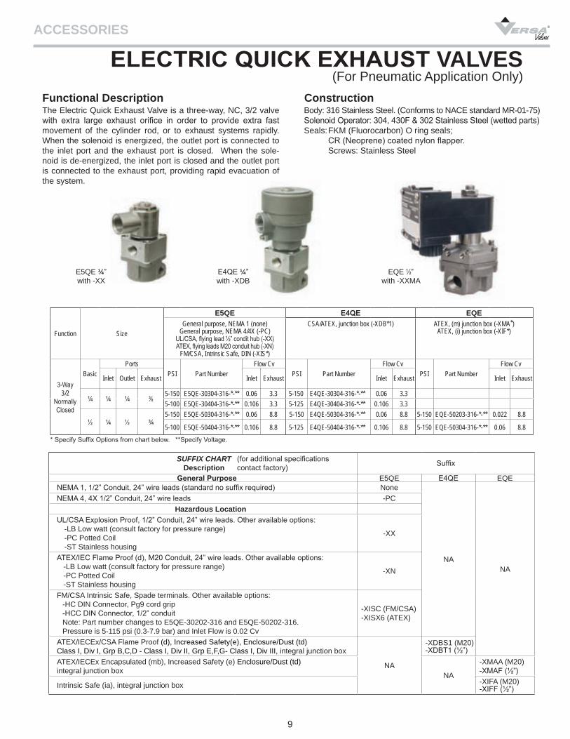
The Electric Quick Exhaust Valve is a three-way, NC, 3/2 valve with extra large exhaust orifice in order to provide extra fast movement of the cylinder rod, or to exhaust systems rapidly. When the solenoid is energized, the outlet port is connected to the inlet port and the exhaust port is closed. When the sole-noid is de-energized, the inlet port is closed and the outlet port is connected to the exhaust port, providing rapid evacuation of the system.
Body: 316 Stainless Steel. (Conforms to NACE standard MR-01-75)Solenoid Operator: 304, 430F & 302 Stainless Steel (wetted parts)Seals: FKM (Fluorocarbon) O ring seals; CR (Neoprene) coated nylon flapper. Screws: Stainless Steel
Construction
ELECTRIC QUICK EXHAUST VALVES(For Pneumatic Application Only)
Functional Description
* Specify Suffix Options from chart below. **Specify Voltage.
E5QE ¼”with -XX
E4QE ¼”with -XDB
EQE ½” with -XXMA
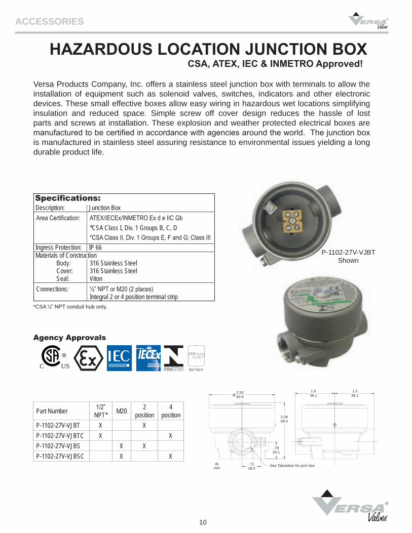
Specifications:Description: Junction BoxArea Certification: ATEX/IECEx/INMETRO Ex d e IIC Gb
*CSA Class I, Div. 1 Groups B, C, D*CSA Class II, Div. 1 Groups E, F and G; Class III
Ingress Protection: IP 66Materials of Construction
Body: 316 Stainless SteelCover: 316 Stainless SteelSeal: Viton
Connections: ½” NPT or M20 (2 places)Integral 2 or 4 position terminal strip
Part Number 1/2” NPT* M20 2
position4
positionP-1102-27V-VJBT X XP-1102-27V-VJBTC X XP-1102-27V-VJBS X XP-1102-27V-VJBSC X X
ACCESSORIES
10
CSA, ATEX, IEC & INMETRO Approved!
Versa Products Company, Inc. offers a stainless steel junction box with terminals to allow the installation of equipment such as solenoid valves, switches, indicators and other electronic devices. These small effective boxes allow easy wiring in hazardous wet locations simplifying insulation and reduced space. Simple screw off cover design reduces the hassle of lost parts and screws at installation. These explosion and weather protected electrical boxes are manufactured to be certified in accordance with agencies around the world. The junction box is manufactured in stainless steel assuring resistance to environmental issues yielding a long durable product life.
Agency Approvals
P-1102-27V-VJBT Shown
HAZARDOUS LOCATION JUNCTION BOX
*CSA ½” NPT conduit hub only.
2.5063.5Ø
2.3459.4
.7118.0
1.538.1
.7920.1
1.538.1
See Tabulation for port sizeINmm
C US®
Size Part Number Pressure Range
Weight Dimensionlbs kg A B
¼” NPT RV-3-316-* 30 to 150 psi 0.16 0.07 0.69” 2.13”½” NPT RV-5-316-* 15 to 150 psi 0.38 0.17 0.875” 3.06”
ACCESSORIES
11
Pressures:
Materials:
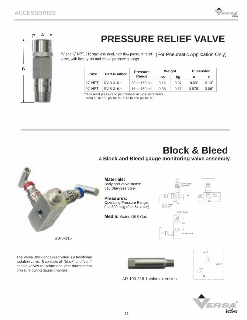
Block & Bleeda Block and Bleed gauge monitoring valve assembly
Body and valve stems:316 Stainless Steel
Operating Pressure Range:0 to 800 psig (0 to 54.4 bar)
AR-190-316-1 valve extension
Media: Water, Oil & Gas
BB-3-316
The Versa Block and Bleed valve is a traditional isolation valve. It consists of “block” and “vent” needle valves to isolate and vent downstream pressure during gauge changes.
PRESSURE RELIEF VALVE(For Pneumatic Application Only)¼” and ½” NPT, 316 stainless steel, high flow pressure relief
valve, with factory set and tested pressure settings
B
A
* Add relief pressure to part number in 5 psi increments from 60 to 150 psi for ¼” & 15 to 150 psi for ½”.
OUT
IN
VENT
2.27 CLOSED2.50 OPEN
1.13.56
1.13.56
2.03
.50
¼” NPT VENT
¼” NPT INLET
3.50
2.27 CLOSED2.50 OPEN
BB-3-316900 WOG316 SSHEAT NUMBER1/4 M X 1/4 FPO#
INLE
T
OU
TLET
VENT
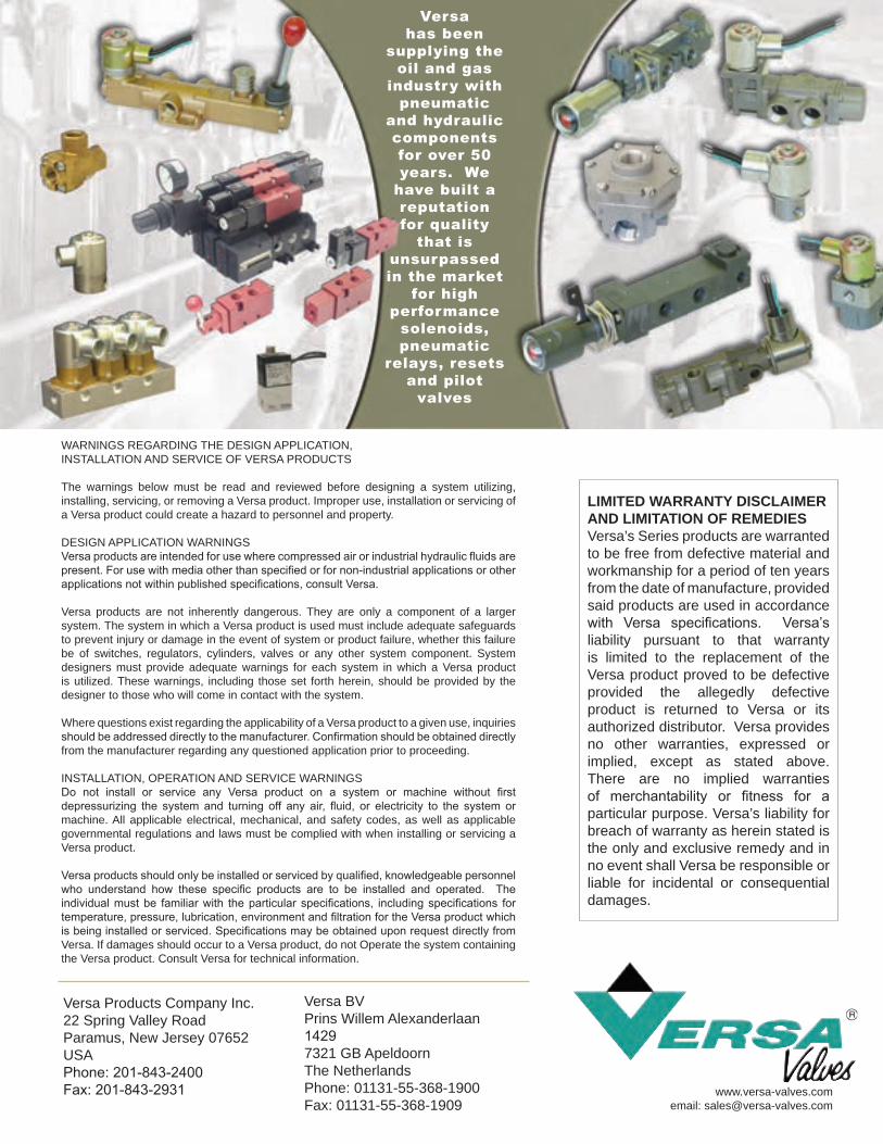
Versa has been
supplying the oil and gas
industry with pneumatic
and hydraulic components for over 50 years. We
have built a reputation for quality
that is unsurpassed in the market
for high performance
solenoids, pneumatic
relays, resets and pilot
valves
WARNINGS REGARDING THE DESIGN APPLICATION,INSTALLATION AND SERVICE OF VERSA PRODUCTS
The warnings below must be read and reviewed before designing a system utilizing, installing, servicing, or removing a Versa product. Improper use, installation or servicing of a Versa product could create a hazard to personnel and property.
DESIGN APPLICATION WARNINGSVersa products are intended for use where compressed air or industrial hydraulic fluids are present. For use with media other than specified or for non-industrial applications or other applications not within published specifications, consult Versa.
Versa products are not inherently dangerous. They are only a component of a larger system. The system in which a Versa product is used must include adequate safeguards to prevent injury or damage in the event of system or product failure, whether this failure be of switches, regulators, cylinders, valves or any other system component. System designers must provide adequate warnings for each system in which a Versa product is utilized. These warnings, including those set forth herein, should be provided by the designer to those who will come in contact with the system.
Where questions exist regarding the applicability of a Versa product to a given use, inquiries should be addressed directly to the manufacturer. Confirmation should be obtained directly from the manufacturer regarding any questioned application prior to proceeding.
INSTALLATION, OPERATION AND SERVICE WARNINGSDo not install or service any Versa product on a system or machine without first depressurizing the system and turning off any air, fluid, or electricity to the system or machine. All applicable electrical, mechanical, and safety codes, as well as applicable governmental regulations and laws must be complied with when installing or servicing a Versa product.
Versa products should only be installed or serviced by qualified, knowledgeable personnel who understand how these specific products are to be installed and operated. The individual must be familiar with the particular specifications, including specifications for temperature, pressure, lubrication, environment and filtration for the Versa product which is being installed or serviced. Specifications may be obtained upon request directly from Versa. If damages should occur to a Versa product, do not Operate the system containing the Versa product. Consult Versa for technical information.
www.versa-valves.comemail: [email protected]
LIMITED WARRANTY DISCLAIMERAND LIMITATION OF REMEDIESVersa’s Series products are warranted to be free from defective material and workmanship for a period of ten years from the date of manufacture, provided said products are used in accordance with Versa specifications. Versa’s liability pursuant to that warranty is limited to the replacement of the Versa product proved to be defective provided the allegedly defective product is returned to Versa or its authorized distributor. Versa provides no other warranties, expressed or implied, except as stated above. There are no implied warranties of merchantability or fitness for a particular purpose. Versa’s liability for breach of warranty as herein stated is the only and exclusive remedy and in no event shall Versa be responsible or liable for incidental or consequential damages.
Versa Products Company Inc.22 Spring Valley RoadParamus, New Jersey 07652USA Phone: 201-843-2400Fax: 201-843-2931
Versa BVPrins Willem Alexanderlaan 14297321 GB ApeldoornThe NetherlandsPhone: 01131-55-368-1900Fax: 01131-55-368-1909