accelerated simulation performance through high ... · accelerated simulation performance through...
TRANSCRIPT
2009 SIMULIA Customer Conference 1
Accelerated Simulation Performance through High Performance Computing for Advanced Sealing
Applications
Frank Popielas, Rohit Ramkumar, Kyle Shaver
Sealing Products Group, Dana Holding Corporation
Harun Bayraktar, Matt Dunbar
SIMULIA
Brian Kucic
R Systems NA, Inc.
Abstract: The automotive and heavy-duty industries are heavy users of Computer Aided
Engineering (CAE) for development, design and performance optimization of their products. As a
technology driven company, the Sealing Products Group of Dana Holding Corporation utilizes
this technology extensively, especially for metal cylinder head gaskets (CHG) and exhaust gaskets,
so called Multi-Layer-Steel (MLS) gaskets. Due to the widespread involvement of complex contact
interactions in high fidelity sealing system analysis, high performance computing is essential to
accelerating the design process, thus meeting aggressive time and cost to market requirements.
Since the release of Abaqus version 6.6 a major step forward was made through the extensive and
effective use of parallel computing. The combination of flexible computing clusters and the power
of parallel processing enabled by SIMULIA resulted in significant time and cost savings for Dana
when using the Abaqus engineering software package. It also allowed for the implementation of
new simulation techniques for contact simulations. This allowed for better and more accurate up-
front prediction of sealing technology.
This paper provides an overview on accelerated simulation performance studies utilizing the latest
SIMULIA technology for advanced sealing application from the Sealing Products Group of Dana
Holding Corp. Furthermore it provides an outlook of steps to come.
Keywords: CAE, High performance computing, cluster, SIMULIA, Abaqus, Dana, sealing
products, contact
2 2009 SIMULIA Customer Conference
1. Introduction
The requirements for better and more effective performance in development, in particular in the
automotive industry became especially important in the current market situation. An ineffective
business will not be able to survive the drastic market challenges regarding cost, quality and
performance. Computer Aided Engineering (CAE) plays a major role in achieving this effectively.
It has been demonstrated that companies focusing heavily on CAE in a coordinated manner are
facing less constraints and have a better chance of coming out of this economic down-turn with
greater ease and an increased focus than companies that do not utilize CAE.
Within this paper we focus on powertrain applications from a sealing products perspective, as used
in the automotive and heavy-duty industries. It outlines the possibilities and different ways to
approach CAE in a cost-effective manner driven by high-performance.
1.1 CAE for Sealing Applications – A brief introduction
1.1.1 CAE applications for the sealing of powertrain and exhaust applications
When talking about CAE applications for the sealing of powertrain and exhaust applications one
first needs to know what is understood to be sealing products. Those products include flat gaskets
and ring seals, rubber-molded gaskets, seals, covers, pans (thermo-plastic and the thermo-set), and
shielding components.
• Flat gaskets and ring seal products, by example:
o Cylinder head gaskets
o Rocker cover gaskets
o Cylinder block hand hole gaskets
o Exhaust manifold gaskets
o Turbo charger gaskets
o Exhaust gas recirculation (EGR) gaskets
o Slip joint gaskets
o V-band gaskets
• Rubber-molded gaskets and seal products, by example:
o Valve cover gaskets
o Cam cover gaskets
o Front cover gaskets
o Window gaskets
2009 SIMULIA Customer Conference 3
o Intake gaskets
o Valve stem seals
o Rubber inserts
• Covers and pan products, by example:
o Valve covers
o Cam covers
o Front covers
o Oil pans
• Shielding component products, by example:
o Exhaust manifold shields
o Down pipe shields
o Sensor shields
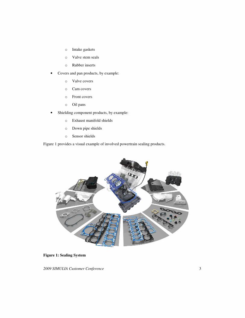
Figure 1 provides a visual example of involved powertrain sealing products.
Figure 1: Sealing System
4 2009 SIMULIA Customer Conference
Those applications range from:
• Low temperatures (below 400ºC) to high temperature (above 1000ºC)
• Quasi-static to dynamic
• Combustion gas to fluid seals
• Thermal to noise shielding
• Thermal reflection to thermal insulation
• Friction withstanding to friction reducing
• Sealing to controlled metering of fluids
This variety of applications demonstrates the challenges and complexity of CAE for those
products including:
• Forming
• Molding
• Contact
• Structural and fluid dynamics simulation and their interaction
• NVH
• Fatigue.
1.1.2 General challenges that need to be considered and addressed
When talking about simulation performance optimization for highly engineered systems we need
to understand the different factors of influence. A major measure for this is the so called “sweet
spot.” This point represents the optimization between scalability (speed up of a simulation) and
cost per unit. Ideally the speed-up factor is increasing linearly with the addition of cores to the
simulation. In reality, however, the software has to be capable of utilizing the hardware
architecture effectively. This shows the need to benchmark each new hardware and software
configuration in order to identify this “sweet spot.”
The diversity of models and their many variations also have an impact on performance. The
knowledge of their influence in conjunction with the software and hardware configuration will
also have a major impact on the cost and time structure in an “analysis driven” business.
2009 SIMULIA Customer Conference 5
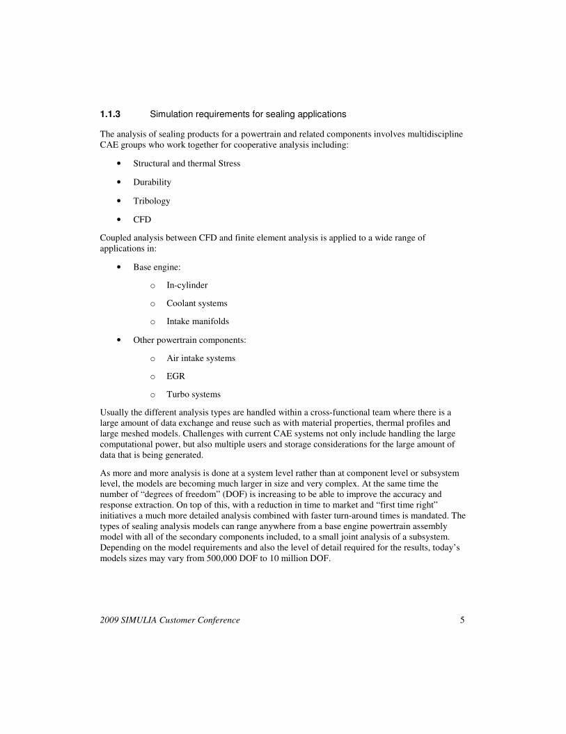
1.1.3 Simulation requirements for sealing applications
The analysis of sealing products for a powertrain and related components involves multidiscipline
CAE groups who work together for cooperative analysis including:
• Structural and thermal Stress
• Durability
• Tribology
• CFD
Coupled analysis between CFD and finite element analysis is applied to a wide range of
applications in:
• Base engine:
o In-cylinder
o Coolant systems
o Intake manifolds
• Other powertrain components:
o Air intake systems
o EGR
o Turbo systems
Usually the different analysis types are handled within a cross-functional team where there is a
large amount of data exchange and reuse such as with material properties, thermal profiles and
large meshed models. Challenges with current CAE systems not only include handling the large
computational power, but also multiple users and storage considerations for the large amount of
data that is being generated.
As more and more analysis is done at a system level rather than at component level or subsystem
level, the models are becoming much larger in size and very complex. At the same time the
number of “degrees of freedom” (DOF) is increasing to be able to improve the accuracy and
response extraction. On top of this, with a reduction in time to market and “first time right”
initiatives a much more detailed analysis combined with faster turn-around times is mandated. The
types of sealing analysis models can range anywhere from a base engine powertrain assembly
model with all of the secondary components included, to a small joint analysis of a subsystem.
Depending on the model requirements and also the level of detail required for the results, today’s
models sizes may vary from 500,000 DOF to 10 million DOF.
6 2009 SIMULIA Customer Conference
1.2 Simulation performance criteria
In the context of High-Performance Computing (HPC) for finite element analysis (FEA), today,
compute clusters are the most common choice. In the last decade, starting with academic and
government research labs, compute clusters started to take over the traditional supercomputers and
large Shared Memory Multi-Processing (SMP) computers. The main driving force behind this
change was the low cost of these clusters which initially were mostly built out of workstation
components and running the open source Linux operating system (OS). Compute clusters are
characterized as a collection of independent compute nodes, usually with their own local disk and
memory subsystem, connected by a high speed interconnect and are often referred to as
Distributed Memory Processing (DMP) system. Today customized turn-key compute clusters are
available from many hardware vendors and are becoming increasingly popular with the simulation
community. While traditionally compute clusters have been more heavily utilized for
Computational Fluid Dynamics (CFD) simulations, owing to increasing model sizes and fidelity,
they are now also being used for FEA. However, efficient utilization of compute clusters requires
Distributed Memory Parallel execution capabilities as well as moreover parallel scalability from
any software that seeks to provide a feasible solution. It is therefore important to be able to
investigate the feasibility of running FEA simulations on compute clusters for particular
workflows.
To calculate the cost of simulations on compute clusters three major contributors must be taken in
to account:
• Software
• Hardware
• Engineering time.
Software cost is relatively straightforward to estimate as long as proper utilization and parallel
computing licensing costs are employed. On the other hand, calculating hardware cost may be a
little more cumbersome. For in-house clusters, the expected life of the cluster, utilization,
maintenance, administration, computer room space, power consumption, and cooling costs should
all be taken in to account. One emerging alternative to in-house cluster computing is using utility
computing services. These services typically charge a fixed amount for each compute node hour
used by the customer with prices depending on the precise configuration of the compute cluster
offered. Once software and hardware cost per hour are known, it is simply a manner of running
representative benchmarks on a range of compute nodes or cores to generate cost curves and
determine the cheapest configuration - alternatively referred to as the “sweet spot”: - to run
simulations. For the purposes of this paper we present a feasibility study using three different
simulations and limit ourselves to analyzing the cost using utility computing services from R
Systems NA, Inc.
2009 SIMULIA Customer Conference 7
1.3 General Simulation Structure
The recent industry push towards DMP computing has led to the advanced development and
scalability of Applied Engineering applications such as Abaqus. This trend has allowed industry
engineers to greatly increase simulation performance while reducing the previously high costs
associated with large SMP compute systems. Replacing the specialized SMP hardware with the
more cost effective, modular, and readily available “node” system DMP models allows for more
than just up-front cost savings. In addition to the bottom line price, the modular architecture of
today’s compute note DMP systems allows for an almost endless array of hardware configurations
and expandability, enabling today’s hardware to meet the flexibility and scalability of the rapidly
changing CAE software.
While cluster computing capabilities of Abaqus/Standard were first introduced with release 6.6,
significant improvements were delivered with later releases. Just before Abaqus 6.7 was released
in 2007, SIMULIA and Dana engaged in the first cluster computing feasibility study. This study
demonstrated that to minimize the simulation cost (i.e. hit the sweet spot) cluster computing with
at least eight compute nodes was a must. This motivated Dana to quickly adopt an in-house cluster
computing solution for their FEA simulations. Such collaborations still continue to date. Most
recently, SIMULIA, Dana, and R Systems worked together on a HPC study which resulted in this
press release [1] on the performance of state-of-the-art cluster computing platforms.
The current analysis environment is composed of a single high performance DMP compute
cluster. Taking advantage of the benefits of DMP expandability have allowed for the seamless
integration of additional, non-identical server nodes to increase the capacity of the HPC. All
controlled by a single head node, there are two independent compute environments defined by
separate parallel environments within the Sun Grid Engine (SGE) job control software. Job
submission and control are managed by SGE and destination queues are specified by users at the
time of job submission. Within the compute nodes, the OS, working, and scratch directories are
all installed on a local raid stripe while the SGE and Engineering application binaries are located
physically on the cluster head node and shared with the compute nodes using NFS. The user
home directories are on a separate NFS mounted share and the head node connects through fiber to
a local SAN device for file storage. Infiniband interconnect hardware connects all of the cluster
nodes and provides the high bandwidth backbone necessary for the simulation processing
performance required to achieve the current benchmark results. A general CAE layout utilizing
cluster architecture is shown in Figure 2.
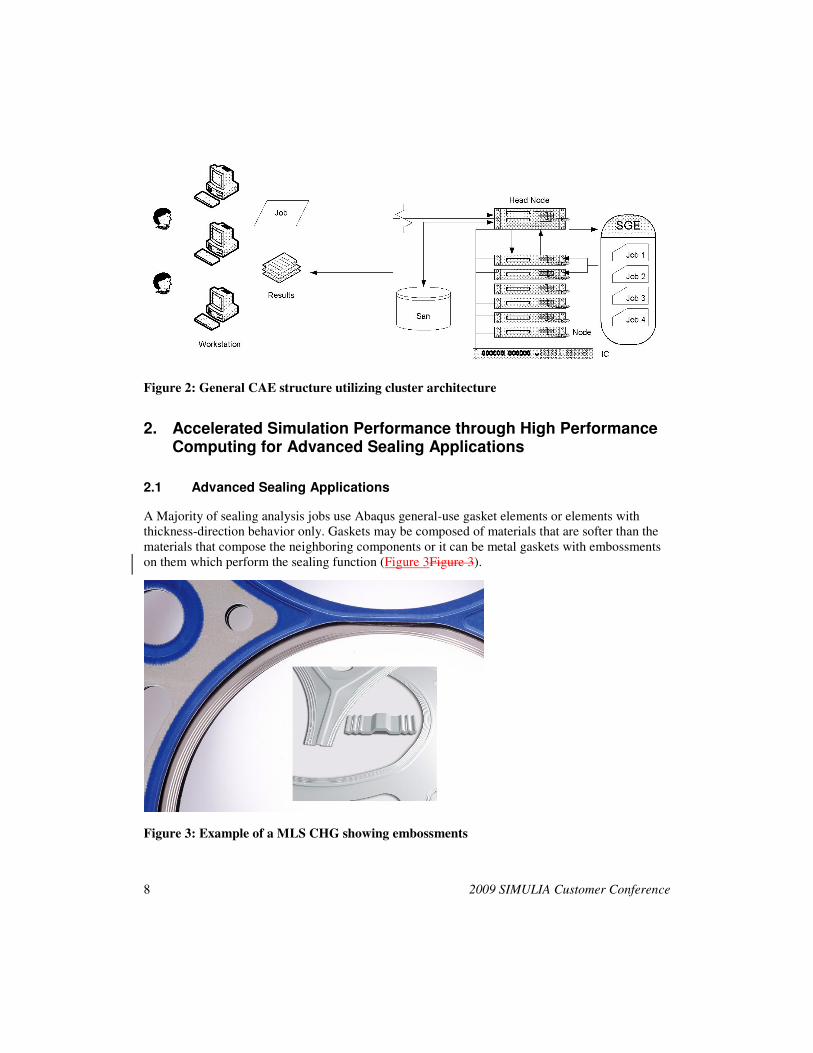
8 2009 SIMULIA Customer Conference
Figure 2: General CAE structure utilizing cluster architecture
2. Accelerated Simulation Performance through High Performance Computing for Advanced Sealing Applications
2.1 Advanced Sealing Applications
A Majority of sealing analysis jobs use Abaqus general-use gasket elements or elements with
thickness-direction behavior only. Gaskets may be composed of materials that are softer than the
materials that compose the neighboring components or it can be metal gaskets with embossments
on them which perform the sealing function (Figure 3Figure 3).
Figure 3: Example of a MLS CHG showing embossments
2009 SIMULIA Customer Conference 9
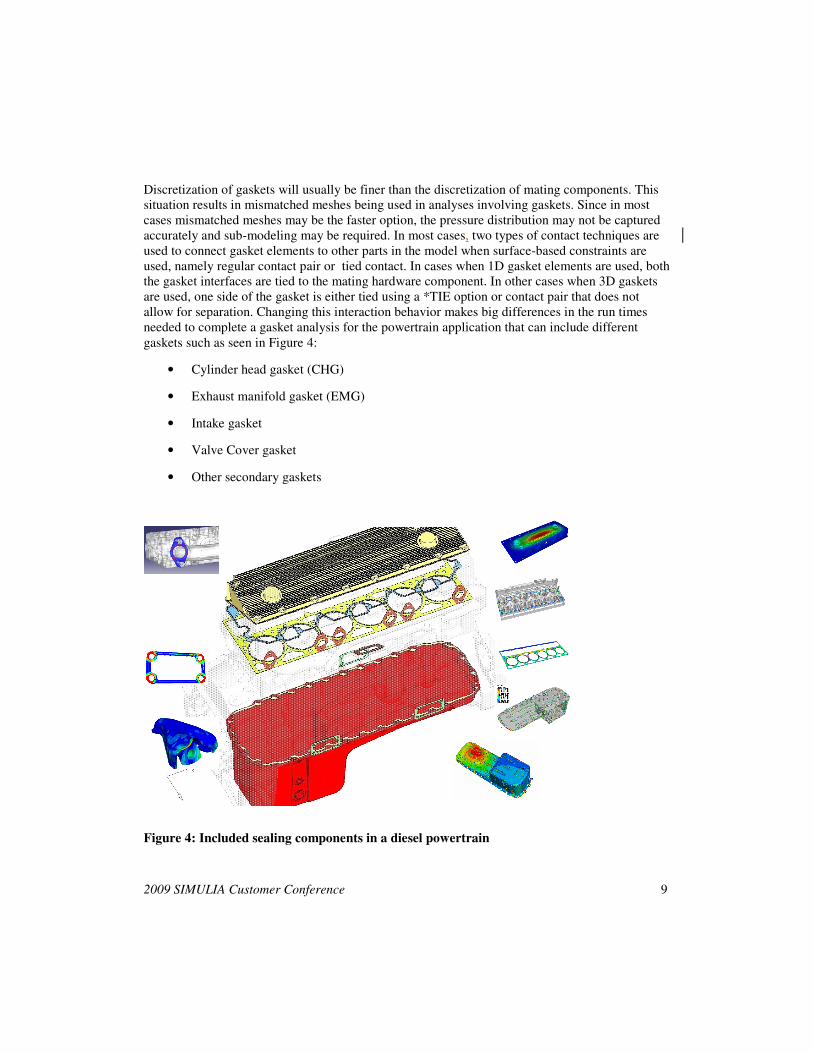
Discretization of gaskets will usually be finer than the discretization of mating components. This
situation results in mismatched meshes being used in analyses involving gaskets. Since in most
cases mismatched meshes may be the faster option, the pressure distribution may not be captured
accurately and sub-modeling may be required. In most cases, two types of contact techniques are
used to connect gasket elements to other parts in the model when surface-based constraints are
used, namely regular contact pair or tied contact. In cases when 1D gasket elements are used, both
the gasket interfaces are tied to the mating hardware component. In other cases when 3D gaskets
are used, one side of the gasket is either tied using a *TIE option or contact pair that does not
allow for separation. Changing this interaction behavior makes big differences in the run times
needed to complete a gasket analysis for the powertrain application that can include different
gaskets such as seen in Figure 4:
• Cylinder head gasket (CHG)
• Exhaust manifold gasket (EMG)
• Intake gasket
• Valve Cover gasket
• Other secondary gaskets
Figure 4: Included sealing components in a diesel powertrain
10 2009 SIMULIA Customer Conference
In current day powertrain applications (more predominantly in automotive industry), most of the
gaskets are a highly optimized lamina of different metals and geometries often referred to as
simply metal gaskets. Depending on the application and the temperature limits that the gasket sees
during the operation of the engine, the metal gasket can be with or without coating. Also the
specific type of coating plays a big role in the convergence of the analysis and the type of
modeling techniques that can be implemented. If more detailed analysis results are required,
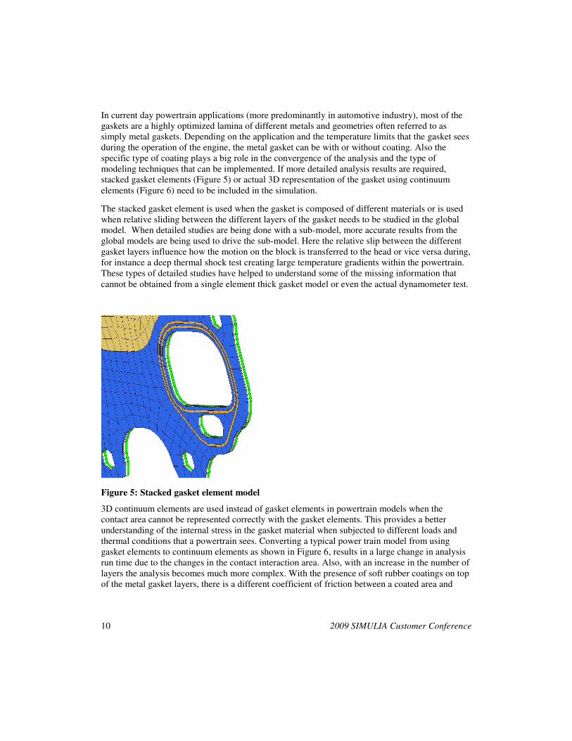
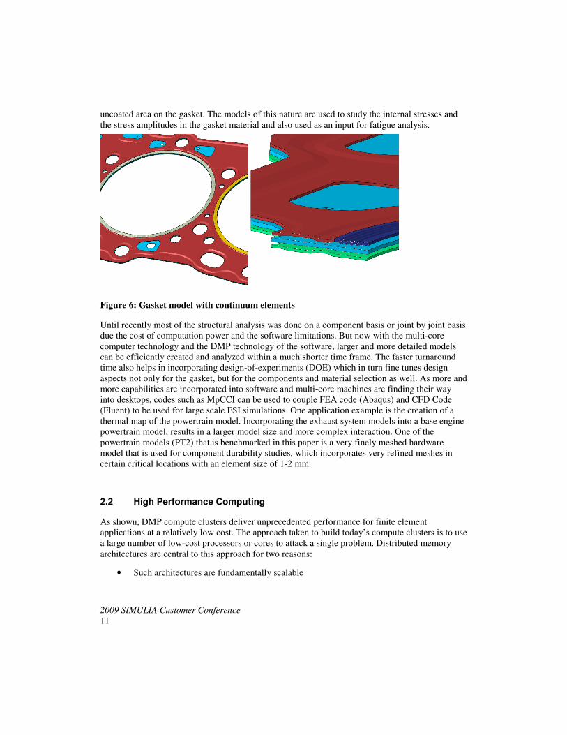
stacked gasket elements (Figure 5) or actual 3D representation of the gasket using continuum
elements (Figure 6) need to be included in the simulation.
The stacked gasket element is used when the gasket is composed of different materials or is used
when relative sliding between the different layers of the gasket needs to be studied in the global
model. When detailed studies are being done with a sub-model, more accurate results from the
global models are being used to drive the sub-model. Here the relative slip between the different
gasket layers influence how the motion on the block is transferred to the head or vice versa during,
for instance a deep thermal shock test creating large temperature gradients within the powertrain.
These types of detailed studies have helped to understand some of the missing information that
cannot be obtained from a single element thick gasket model or even the actual dynamometer test.
Figure 5: Stacked gasket element model
3D continuum elements are used instead of gasket elements in powertrain models when the
contact area cannot be represented correctly with the gasket elements. This provides a better
understanding of the internal stress in the gasket material when subjected to different loads and
thermal conditions that a powertrain sees. Converting a typical power train model from using
gasket elements to continuum elements as shown in Figure 6, results in a large change in analysis
run time due to the changes in the contact interaction area. Also, with an increase in the number of
layers the analysis becomes much more complex. With the presence of soft rubber coatings on top
of the metal gasket layers, there is a different coefficient of friction between a coated area and
2009 SIMULIA Customer Conference
11
uncoated area on the gasket. The models of this nature are used to study the internal stresses and
the stress amplitudes in the gasket material and also used as an input for fatigue analysis.
Figure 6: Gasket model with continuum elements
Until recently most of the structural analysis was done on a component basis or joint by joint basis
due the cost of computation power and the software limitations. But now with the multi-core
computer technology and the DMP technology of the software, larger and more detailed models
can be efficiently created and analyzed within a much shorter time frame. The faster turnaround
time also helps in incorporating design-of-experiments (DOE) which in turn fine tunes design
aspects not only for the gasket, but for the components and material selection as well. As more and
more capabilities are incorporated into software and multi-core machines are finding their way
into desktops, codes such as MpCCI can be used to couple FEA code (Abaqus) and CFD Code
(Fluent) to be used for large scale FSI simulations. One application example is the creation of a
thermal map of the powertrain model. Incorporating the exhaust system models into a base engine
powertrain model, results in a larger model size and more complex interaction. One of the
powertrain models (PT2) that is benchmarked in this paper is a very finely meshed hardware
model that is used for component durability studies, which incorporates very refined meshes in
certain critical locations with an element size of 1-2 mm.
2.2 High Performance Computing
As shown, DMP compute clusters deliver unprecedented performance for finite element
applications at a relatively low cost. The approach taken to build today’s compute clusters is to use
a large number of low-cost processors or cores to attack a single problem. Distributed memory
architectures are central to this approach for two reasons:
• Such architectures are fundamentally scalable
12 2009 SIMULIA Customer Conference
• Relatively low cost because the hardware has no burden of sharing memory between a
large numbers of cores.
The downside of compute clusters is that software must be specifically written to execute on
distributed memory architectures which presents a major software development challenge.
A key hurdle in enabling distributed memory execution for a non-linear implicit finite element
application like Abaqus/Standard is the solution of a large system of linear equations that is
repeated with each solution iteration. This problem can be tackled with either direct linear
equation solvers which are very robust but difficult to parallelize, or with an iterative equation
solver which generally parallelize well but may not converge for many problems. With Abaqus 6.7
the SIMULIA development team released a direct linear equation solver that executes efficiently
on distributed memory architectures. SIMULIA has refined this technology with Abaqus 6.8 and
6.9 and will continue to enhance this solver with future releases.
Two directions seen in today’s hardware have driven and enabled SIMULIA to approach
delivering high performance for Abaqus/Standard. The first is that while hardware vendors have
lost the ability to cost-effectively deliver significant speedups from scalar (non-parallel)
processors, the vendors have been successful in delivering many cores in a single processor at a
similar cost to the single-core processors of several years back. The second relates to networking
technology, commonly referred in the HPC community as interconnect technology, having made
great strides allowing large volumes of data to be moved quickly between processors. Networks
continue to improve at the same time that hardware vendors continue to pack more cores into each
processor which opens doors for parallel applications to deliver better performance at a fixed cost.
2.3 Performance Studies
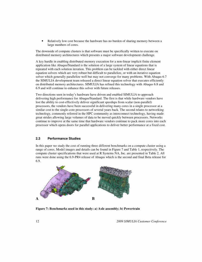
In this paper we study the cost of running three different benchmarks on a compute cluster using a
range of cores. Model images and details can be found in Figure 7 and Table 1, respectively. The
compute cluster specifications that were used at R Systems NA, Inc. are presented in Table 2. All
runs were done using the 6.9-PR4 release of Abaqus which is the second and final Beta release for
6.9.
A B
Figure 7: Benchmarks used in this study: a) Axle assembly; b) Powertrain
2009 SIMULIA Customer Conference
13
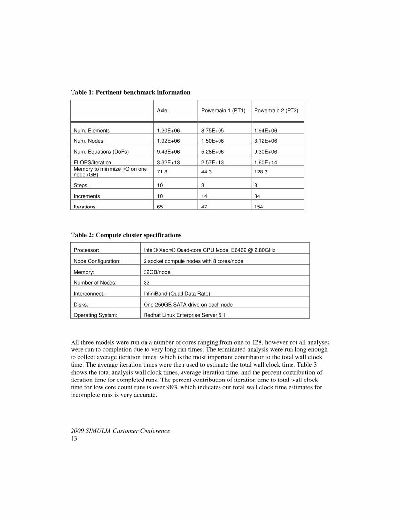
Table 1: Pertinent benchmark information
Axle Powertrain 1 (PT1) Powertrain 2 (PT2)
Num. Elements 1.20E+06 8.75E+05 1.94E+06
Num. Nodes 1.92E+06 1.50E+06 3.12E+06
Num. Equations (DoFs) 9.43E+06 5.28E+06 9.30E+06
FLOPS/iteration 3.32E+13 2.57E+13 1.60E+14
Memory to minimize I/O on one node (GB)
71.8 44.3 128.3
Steps 10 3 8
Increments 10 14 34
Iterations 65 47 154
Table 2: Compute cluster specifications
Processor: Intel® Xeon® Quad-core CPU Model E6462 @ 2.80GHz
Node Configuration: 2 socket compute nodes with 8 cores/node
Memory: 32GB/node
Number of Nodes: 32
Interconnect: InfiniBand (Quad Data Rate)
Disks: One 250GB SATA drive on each node
Operating System: Redhat Linux Enterprise Server 5.1
All three models were run on a number of cores ranging from one to 128, however not all analyses
were run to completion due to very long run times. The terminated analysis were run long enough
to collect average iteration times which is the most important contributor to the total wall clock
time. The average iteration times were then used to estimate the total wall clock time. Table 3
shows the total analysis wall clock times, average iteration time, and the percent contribution of
iteration time for completed runs. The percent contribution of iteration time to total wall clock
time for low core count runs is over 98% which indicates our total wall clock time estimates for
incomplete runs is very accurate.
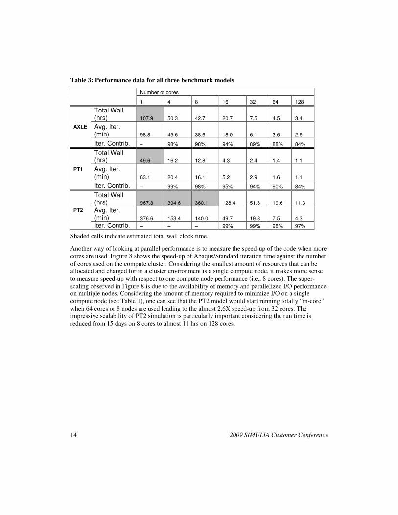
14 2009 SIMULIA Customer Conference
Table 3: Performance data for all three benchmark models
Number of cores
1 4 8 16 32 64 128
AXLE
Total Wall (hrs) 107.9 50.3 42.7 20.7 7.5 4.5 3.4
Avg. Iter. (min) 98.8 45.6 38.6 18.0 6.1 3.6 2.6
Iter. Contrib. – 98% 98% 94% 89% 88% 84%
PT1
Total Wall (hrs) 49.6 16.2 12.8 4.3 2.4 1.4 1.1
Avg. Iter. (min) 63.1 20.4 16.1 5.2 2.9 1.6 1.1
Iter. Contrib. – 99% 98% 95% 94% 90% 84%
PT2
Total Wall (hrs) 967.3 394.6 360.1 128.4 51.3 19.6 11.3
Avg. Iter. (min) 376.6 153.4 140.0 49.7 19.8 7.5 4.3
Iter. Contrib. – – – 99% 99% 98% 97%
Shaded cells indicate estimated total wall clock time.
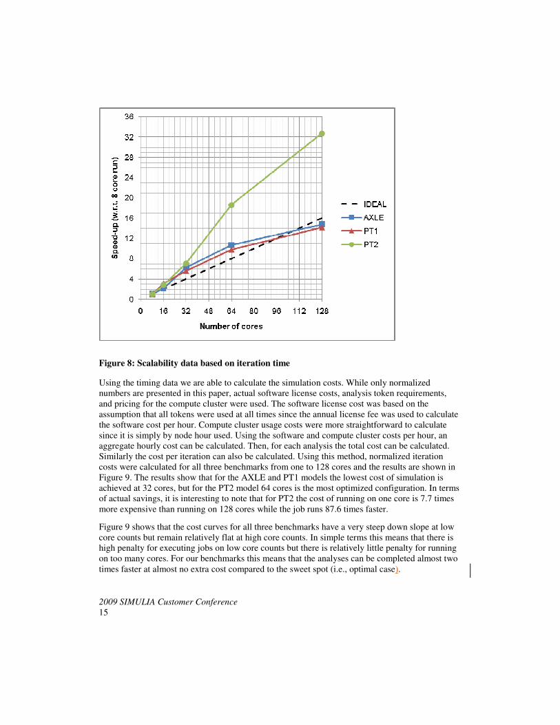
Another way of looking at parallel performance is to measure the speed-up of the code when more
cores are used. Figure 8 shows the speed-up of Abaqus/Standard iteration time against the number
of cores used on the compute cluster. Considering the smallest amount of resources that can be
allocated and charged for in a cluster environment is a single compute node, it makes more sense
to measure speed-up with respect to one compute node performance (i.e., 8 cores). The super-
scaling observed in Figure 8 is due to the availability of memory and parallelized I/O performance
on multiple nodes. Considering the amount of memory required to minimize I/O on a single
compute node (see Table 1), one can see that the PT2 model would start running totally “in-core”
when 64 cores or 8 nodes are used leading to the almost 2.6X speed-up from 32 cores. The
impressive scalability of PT2 simulation is particularly important considering the run time is
reduced from 15 days on 8 cores to almost 11 hrs on 128 cores.
2009 SIMULIA Customer Conference
15
Figure 8: Scalability data based on iteration time
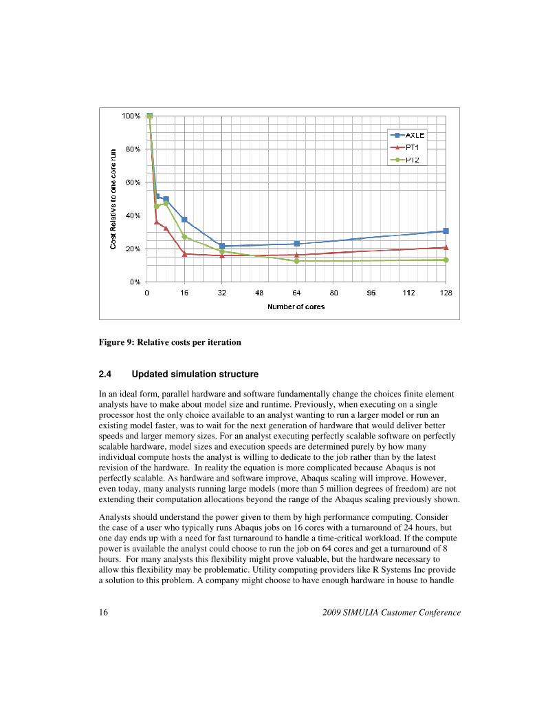
Using the timing data we are able to calculate the simulation costs. While only normalized
numbers are presented in this paper, actual software license costs, analysis token requirements,
and pricing for the compute cluster were used. The software license cost was based on the
assumption that all tokens were used at all times since the annual license fee was used to calculate
the software cost per hour. Compute cluster usage costs were more straightforward to calculate
since it is simply by node hour used. Using the software and compute cluster costs per hour, an
aggregate hourly cost can be calculated. Then, for each analysis the total cost can be calculated.
Similarly the cost per iteration can also be calculated. Using this method, normalized iteration
costs were calculated for all three benchmarks from one to 128 cores and the results are shown in
Figure 9. The results show that for the AXLE and PT1 models the lowest cost of simulation is
achieved at 32 cores, but for the PT2 model 64 cores is the most optimized configuration. In terms
of actual savings, it is interesting to note that for PT2 the cost of running on one core is 7.7 times
more expensive than running on 128 cores while the job runs 87.6 times faster.
Figure 9 shows that the cost curves for all three benchmarks have a very steep down slope at low
core counts but remain relatively flat at high core counts. In simple terms this means that there is
high penalty for executing jobs on low core counts but there is relatively little penalty for running
on too many cores. For our benchmarks this means that the analyses can be completed almost two
times faster at almost no extra cost compared to the sweet spot (i.e., optimal case).
16 2009 SIMULIA Customer Conference
Figure 9: Relative costs per iteration
2.4 Updated simulation structure
In an ideal form, parallel hardware and software fundamentally change the choices finite element
analysts have to make about model size and runtime. Previously, when executing on a single
processor host the only choice available to an analyst wanting to run a larger model or run an
existing model faster, was to wait for the next generation of hardware that would deliver better
speeds and larger memory sizes. For an analyst executing perfectly scalable software on perfectly
scalable hardware, model sizes and execution speeds are determined purely by how many
individual compute hosts the analyst is willing to dedicate to the job rather than by the latest
revision of the hardware. In reality the equation is more complicated because Abaqus is not
perfectly scalable. As hardware and software improve, Abaqus scaling will improve. However,
even today, many analysts running large models (more than 5 million degrees of freedom) are not
extending their computation allocations beyond the range of the Abaqus scaling previously shown.
Analysts should understand the power given to them by high performance computing. Consider
the case of a user who typically runs Abaqus jobs on 16 cores with a turnaround of 24 hours, but
one day ends up with a need for fast turnaround to handle a time-critical workload. If the compute
power is available the analyst could choose to run the job on 64 cores and get a turnaround of 8
hours. For many analysts this flexibility might prove valuable, but the hardware necessary to
allow this flexibility may be problematic. Utility computing providers like R Systems Inc provide
a solution to this problem. A company might choose to have enough hardware in house to handle
2009 SIMULIA Customer Conference
17
routine compute needs, but choose to relieve a computing peak by moving computation to an off-
site resource provider.
One obstacle to doing computations at remote locations still remains - post processing the model.
A large Abaqus analysis may generate tens of gigabytes of output data. Transferring this data from
a remote compute site back to the user’s local workstation over the Internet may take 12-24 hours
which often negates the benefits obtained by making use of remote computing resources. A
solution to this problem is emerging in a variety of products, both commercially available and
open sourced. The solution is to do the graphics processing on a machine co-located near the
remote compute cluster and then send compressed images back to the user’s machine. Although
for Abaqus post processing solutions tailored to 3D graphics must be used, the approach is very
similar to the commonly used Windows Remote Desktop or VNC desktop solutions.
In practice there is a minimum network bandwidth that must be available to employ these types of
remote graphics solutions. A basic rule of thumb is that 1 megabit per second of bandwidth is
required for every frame per second a user wants. SIMULIA engineers have done some initial
testing with this approach to post processing and have found that Abaqus/Viewer can be
reasonably used for large models with bandwidths of about 3-5 Mbits/sec.
The advances in compute system capabilities have quickly brought on an increased need for
remote visualization tools. The ideal consolidation of large simulation systems which would
allow for increased computational capacity and reduced administration costs could be further
accelerated through improvements in remote visualization components. Whether reviewing
inputs, checking on simulations in progress, or needing to quickly view results, the need for such
utilities must not be overlooked.
Today’s tools for remote visualization provide an efficient way for engineers to interact
graphically with their simulations at locations other than a directly connected terminal monitor.
The network ODB viewer which is built into Abaqus and third-party tools such as Hewlett-
Packard’s Remote Graphics software provide the basic requirements for the remote visualization
of Abaqus simulations. Still, further developments of remote visualization tools could provide
geographically dispersed system users to share a larger compute system with a perceived
experience of being located in front of the actual system. Graphically, object manipulation is a
limiting factor of the current tools used for remote visualization. Influences such as network
bandwidth and system resources on both the client and server sides of the visualization tools have
a large effect on the overall remote visualization experience. Not surprisingly, the further both
geographically and by total number of interim network “hops” away from the data source that a
remote user is located, the more degraded the visualization experience will be. With acceptable
usability bandwidth requirement of between 3 and 5 Mbits/sec. for today’s remote visualization
tools, the supporting environment is limited mainly to local LAN setups. In a business
environment where network resources are in competition with other business process, an ideal
solution is to have a separate LAN dedicated to this purpose.
18 2009 SIMULIA Customer Conference
2.5 Future technology
Over the past 5 years SIMULIA has been working to re-architect the Abaqus products to run on
distributed memory architectures after many years of single processors and then shared-memory
parallel execution. Users may ask whether a new architecture is going to emerge in the next 5 to
10 years. The answer to this question is yes and no. Parallel computing continues to be the most
obvious avenue to delivering unlimited performance, and both software developers and hardware
vendors continue to learn how to better deliver parallel solutions to end users. Improvements in
the performance of individual scalar compute cores continue to be made, but at a very slow rate.
A major concern in parallel computing is power consumption, and this is one of the focus areas of
future technology. One approach is to use lower-speed, lower-power processors, but to use more
of them as the power savings to be gained from lowering clock speeds more than offsets the use of
more cores. This approach is represented by IBM’s BlueGene supercomputer and by the products
of companies like SiCortex which couple relatively low speed processors with fast interconnects
to deliver very good performance for applications that can effectively exploit a highly parallel
architecture.
A second approach to lowering power consumption and delivering greater performance is to use
graphics processors for general purpose computing (GPGPU). This represents a significant
software challenge, but the performance gains that can be delivered by executing appropriate code
on GPGPU’s are significant. Currently codes being tested on GPGPU’s typically execute using a
single GPGPU (the code executing on the GPGPU runs many parallel streams of execution), but
going forward it is an obvious step to start deploying many GPGPU’s to work in parallel on single
problem.
3. Conclusion
In order to meet today’s fast-paced development requirements, up-front simulation techniques play
a major role. As such, for an efficient CAE implementation to be successful, the right system
environment is needed. The optimal performance must be known for the specific product portfolio
as the diversity of models have significant influence on the sweet spot. On top of that the
performance of the software for different hardware structures varies.
In order to meet the challenges of our time for advanced sealing solutions in the automotive and
heavy duty environment, the synergy between the Abaqus FEA solver and multi-node HPC
clusters is used to minimize the unit cost and retain the optimal turn-around time. Exceptional is
the fact that with Abaqus V6.9 the costs are not increasing with respect to the future powertrain
model (PT2) having a sweet spot of 64 cores. This is important when scheduling the work load
based on timing needs in order to decrease turn-around time. In the past after reaching the sweet
spot, costs would increase again. In our case the cost are almost flat when reaching 32 cores
making the life of an analyst, who is always fighting to meet deadlines, much easier.
Further optimization of the cost structure and performance can be reached through remote
visualization. The technology and infrastructure though have still to be improved in order to make
this a viable solution in a cost effective way.

2009 SIMULIA Customer Conference
19
4. References
1. Dassault Systèmes Announces Accelerated Simulation Performance with Microsoft’s
Windows HPC Server 2008, Press Release, 2008,
http://www.simulia.com/news/pr_081015_DSS.html