acc_2014_yasha_parvini
TRANSCRIPT

Preliminary Results on Identification of an Electro-Thermal Model for Low Temperature
and High Power Operation of Cylindrical Double Layer Ultracapacitors
Yasha Parvini, Jason B. Siegel, Anna G. Stefanopoulou, Ardalan Vahidi
American Control Conference Portland, OR
June 4, 2014
1

Motivation
Ultracapacitor Advantages:
• High power density • Reliable performance in harsh environments (low and high temperatures) • Low impedance • Virtually unlimited cycle life
• Modelling the ultracapacitor at low temperatures and high power operation conditions to study cold start performance
2
Outline
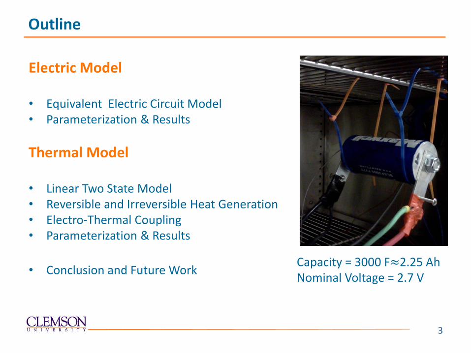
Electric Model • Equivalent Electric Circuit Model • Parameterization & Results
Thermal Model • Linear Two State Model • Reversible and Irreversible Heat Generation • Electro-Thermal Coupling • Parameterization & Results
• Conclusion and Future Work
Capacity = 3000 F≈2.25 Ah Nominal Voltage = 2.7 V
3

Electrical Model of the Ultracapacitor
• Identification is done by minimizing the least square error between the measured and simulated voltages at each time instant.
𝐽 = 𝑚𝑖𝑛 (𝑉𝑚(𝑘) − 𝑉𝑇(𝑘))2
𝑘
• This study will also determine the number of RC pairs.
Equivalent Electric Circuit Model: Electrical
Model (Rs, Ri, Ci)
Current Terminal Voltage
4

0 100 200 300 400 500 600 700 800 900-200
-100
0
100
200
Time (s)
Cu
rren
t(A
)
0 100 200 300 400 500 600 700 800 900-1
0
1
2
3
Vo
lta
ge(V
)
Current
Voltage
Pulse-relaxation test at -40°C and 191A current
Test Procedure for Parameterization of the Electrical Model
• 5% Pulse-Relaxation which the battery is charged from 0% SOC with constant current to 5% SOC and then relaxed for 20 seconds. The procedure is repeated to 100% SOC and similarly for discharging.
Currents (Amps) 191, 135,
67.5,22.5
SOC Range (%) 0-100
Temperatures (℃) -40, -20, 0
5

Determination of the Cell Open Circuit Voltage and Capacity
• OCV and cell capacity are determined based on low current cycling test at a rate of C/5 (0.45Amps).
• Despite the ideal capacitor with a linear OCV The C/5 data shows that the OCV of the cell is actually nonlinear.
0 0.2 0.4 0.6 0.8 10
0.5
1
1.5
2
2.5
SOC
Vo
lta
ge (
V)
Experimental
Ideal
6

0 100 200 300 400 500 600 700 800 9000
0.5
1
1.5
2
2.5
Vo
lta
ge (
V)
Measurement
Model
0 100 200 300 400 500 600 700 800 900-0.03
-0.02
-0.01
0
0.01
0.02
Time (S)
Vo
lta
ge-E
rro
r (
V)
520 530 540 550
2.1
2.2
2.3
Vo
lta
ge (
V)
Model RMSE(mV)
Linear-OCV-Rs 81
Nonlinear-OCV-Rs 16
Nonlinear-OCV-Rs-RC 9
Parameterization Results
Results for the pulse test at -20°C and 135A
7

Thermal Model of the Ultracapacitor
* Youngki Kim, Jason B. Siegel and Anna G. Stefanopoulou, ” A Computationally Efficient Thermal Model of Cylindrical Battery Cells for the Estimation of Radially Distributed Temperatures ” In 2013 American Control Conference, June 2013.
*
Thermal Model
(Cp, h, kt, 𝜹)
Heat Generation Surface Temperature
Core Temperature Ambient Temperature
8

• Joule Heating (Irreversible) which is the heat generated due to resistive losses and is equal to :
• Reversible Heat Generation which is due to change of entropy in the
cell and is governed by:
Reversible and Irreversible Heat Generation
0 2000 4000 6000 8000 10000 12000 14000 16000 18000-20
-18
-16
-14
-12
-10
-8
Time (S)
Tem
pera
tu
re (
oC
)
SOC(50-100),Rest=90s
SOC(0-100),Rest=90s
SOC(50-100),Rest=0s
SOC(0-100),Rest=0s
5200 5400 5600-9.4-9.2
-9-8.8-8.6-8.4
Thermal pulse tests at -20°C and 140A
Total heat generation consists of two parts:
9

Electro-Thermal Coupling
• The electrical and thermal models are coupled through total heat generation and temperature dependent electrical parameters.
10

• Constant current pulses (charging/discharging) with 90 and 0 second rest in between until the temperature reaches steady state are used to exercise the thermal model.
Currents(Amps) SOC Range (%) T(℃)
140, 100, 50 (0-100)&(50-100) -20
Test Procedure for Parameterization of the Thermal Model
11

Parameterization Problem Setup
• Thermal parameters (Cp, h, Kt ,𝛿) are identified by minimizing the least square error between the measured and simulated surface temperatures at each time instant.
𝐽 = 𝑚𝑖𝑛 (𝑇𝑚(𝑘) − 𝑇𝑠(𝑘))2
𝑘
• The minimization problem is solved using nonlinear optimization functions in Matlab.
12

Parameterization Results for the Thermal Model
0 2000 4000 6000 8000 10000 12000 14000 16000 18000-20
-18
-16
-14
-12
-10
-8
Time (s)
Tem
pera
ture (
C)
Measured
Estimated
5000 5200-9.4
-9.2
-9
-8.8
-8.6
Result for -20°C, 140A, zero rest and SOC range of 0 to 100
13

Conclusion and Future Work
• Single RC model with non-linear OCV mapping is accurate enough in capturing the terminal voltage behavior of the UC at sub-zero temperatures, different current rates and the whole SOC range.
• Parameterization of the thermal model for ultracapacitor was developed considering the entropic heat generation effect.
• The electro-thermal model will allow studying the hybrid Battery/UC at low temperature operations and also cold starting applications and also the benefits of hybridizing on battery life.
14

ACKNOWLEDGMENT
• The authors wish to acknowledge the technical and financial support of automotive research center (ARC) in accordance to agreement W56HZV-04-2-0001 with TARDEC.
15

Thank You!
16